Embed Size (px)
Citation preview
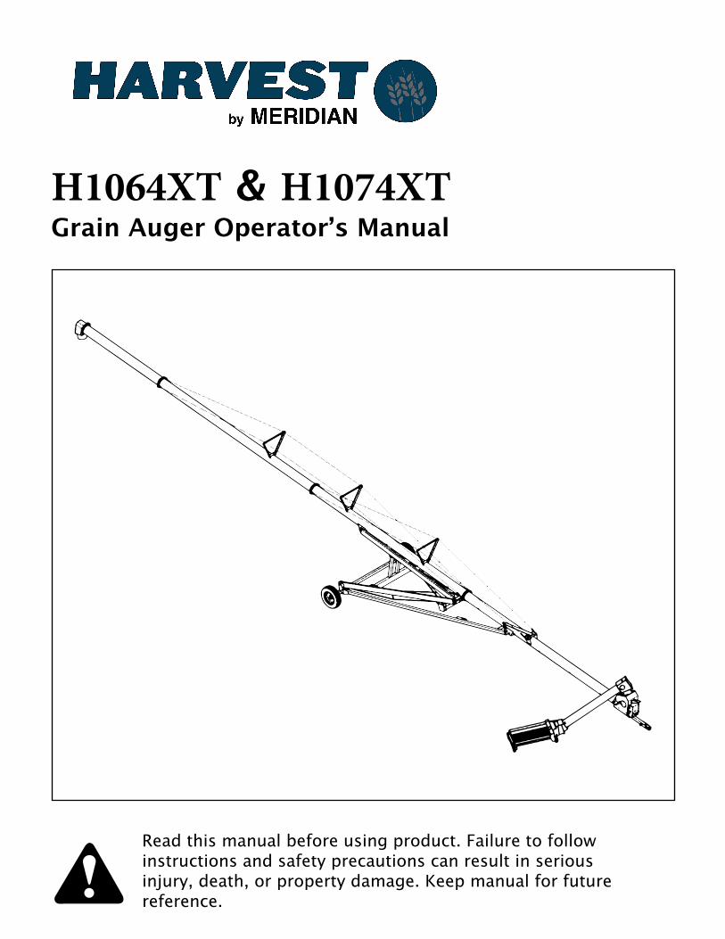
Read this manual before using product. Failure to follow instructions and safety precautions can result in serious injury, death, or property damage. Keep manual for future reference.
H1064XT & H1074XT *UDLQ�$XJHU�2SHUDWRU·V�0DQXDO
H10XX Series Augers:Important Notes
At 15-20 miles, tire lug nut tightness and wheel hub temperature need to be checked.
At 50-60 miles, check these a second time.
For all models, the maximum transport speed is 45 mph.

Harvest by Meridian thanks you for your purchase of the best quality auger on the market. We are proud to have you on our team. Our equipment is manufactured in the United States of America and is made to improve your farming operation. Before you operate this auger, we advise that you read this manual and familiarize yourself with each of the features. Please take all the precautions necessary for an efficient and safe operation. Harvest by Meridian recommends that anyone using this auger read the operational manual and sign on the sheet provided below. This is to be kept for your record keeping.
Date Employee Name Employee Signature
2
TABLE OF CONTENTS
1. Introduction_____________________________________________________________42. Safety First______________________________________________________________53. Transportation & Placement_____________________________________________6
3.1 Before Transporting Your Auger___________________________________63.2 Transport Procedure_______________________________________________73.3 Placement of Auger________________________________________________73.4 Final Placement___________________________________________________93.5 Lowering the Auger_______________________________________________9
4. Operation______________________________________________________________104.1 Pre-Operation Checklist__________________________________________104.2 Auger Drive & Lockout___________________________________________104.3 Start Up & Break In_______________________________________________114.4 Everyday Operation______________________________________________124.5 Shutting Down the Auger_________________________________________124.6 Completion & Cleanup___________________________________________134.7 Lowering the Auger______________________________________________13
5. Hydraulics_____________________________________________________________145.1 General Information______________________________________________145.2 Cylinder Hydraulics______________________________________________15
6. Storage & Maintenance_________________________________________________166.1 General Maintenance_____________________________________________166.2 Storage of Auger_________________________________________________17
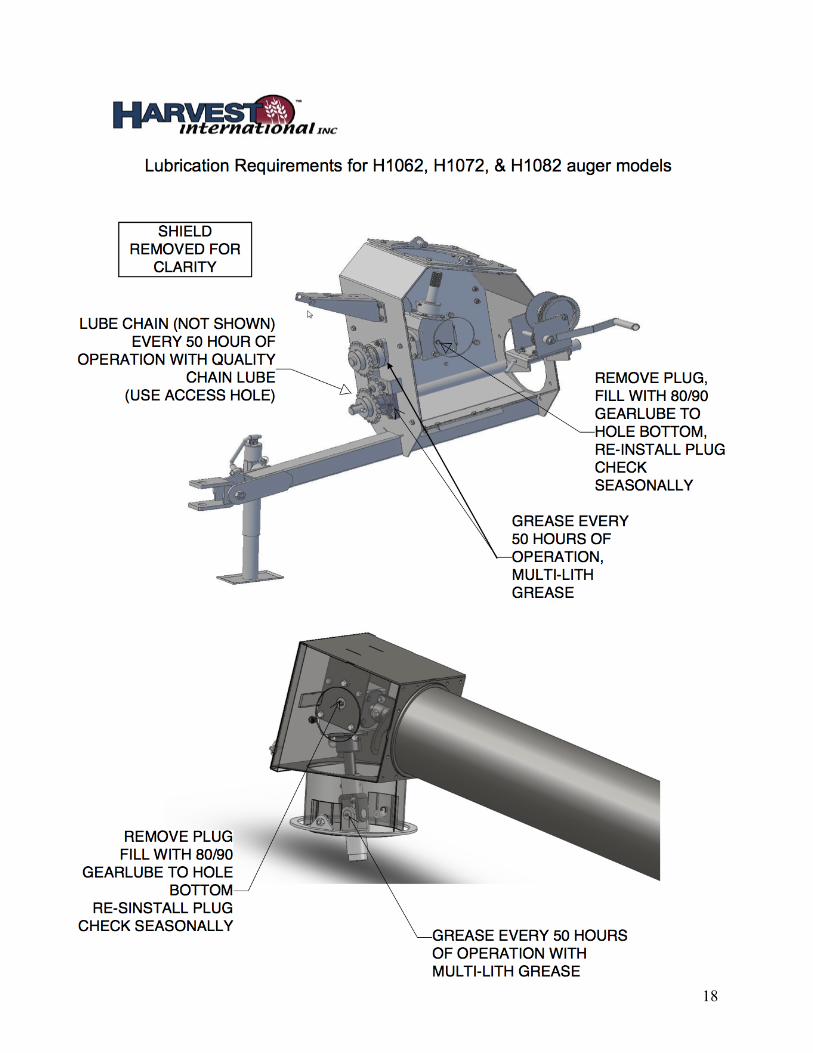
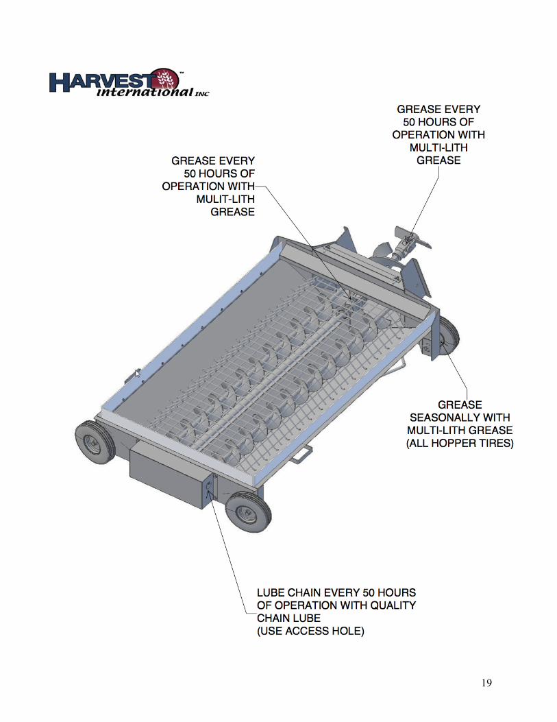
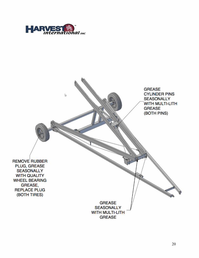
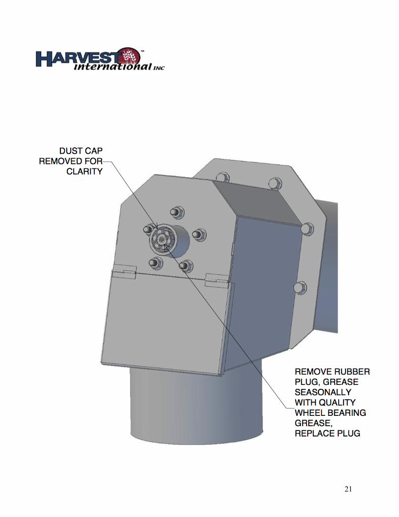
7. Appendix & Forms_____________________________________________________18Lubrication Requirements____________________________________________18 PTO Lubrication______________________________________________________22 H1064XT & 74XT Parts Book____________________________________________23 Warranty Policy & Forms______________________________________________49
3
1. IntroductionCongratulations on your choice of a Harvest by Meridian auger! This equipment has been designed and manufactured to meet the needs of the discerning buyer.
Safe and efficient operation of your auger requires that you, and anyone else who will be operating or maintaining the auger, read and understand the safety, operation, maintenance, and troubleshooting information in this manual.
Keep this manual handy for frequent reference and to pass on to new operators or owners. Call your Harvest by Meridian distributor or dealer if you need assistance, information, or additional copies of the manual.
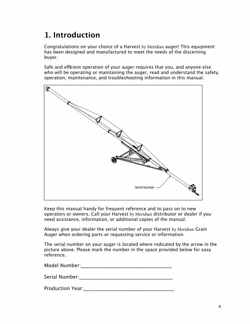
Always give your dealer the serial number of your Harvest by Meridian Grain Auger when ordering parts or requesting service or information.
The serial number on your auger is located where indicated by the arrow in the picture above. Please mark the number in the space provided below for easy reference.
Model Number:_____________________________________
Serial Number:______________________________________
Production Year:_____________________________________
4

2. Safety First
Safety is a priority in your everyday work habit, especially if you work with machinery. Whether you are an owner, an operator, or an employee, it is your responsibility to know the operational requirements and safety precautions of the machinery.
Why is safety important to you?
1. Accidents disable and kill.2. Accidents cost.
3. Accidents can be avoided.
SIGNAL WORDS:Note the use of the signal words DANGER, WARNING, CAUTION, and NOTICE with the safety messages. The safety alert symbol identifies imminent and potential hazards to personal health and safety. The appropriate signal word for each message has been selected using the definitions below as a guideline:
DANGER: indicates an imminently hazardous situation that, ifnot avoided, will result in serious injury or death.
WARNING: Indicates a hazardous situation that, if not avoided,could result in serious injury or death.
CAUTION: Indicates a hazardous situation that, if not avoided,may result in minor or moderate injury.
NOTICE: Indicates a potentially hazardous situation that, if notavoided, may result in property damage.
5
3. Transportation and Placement
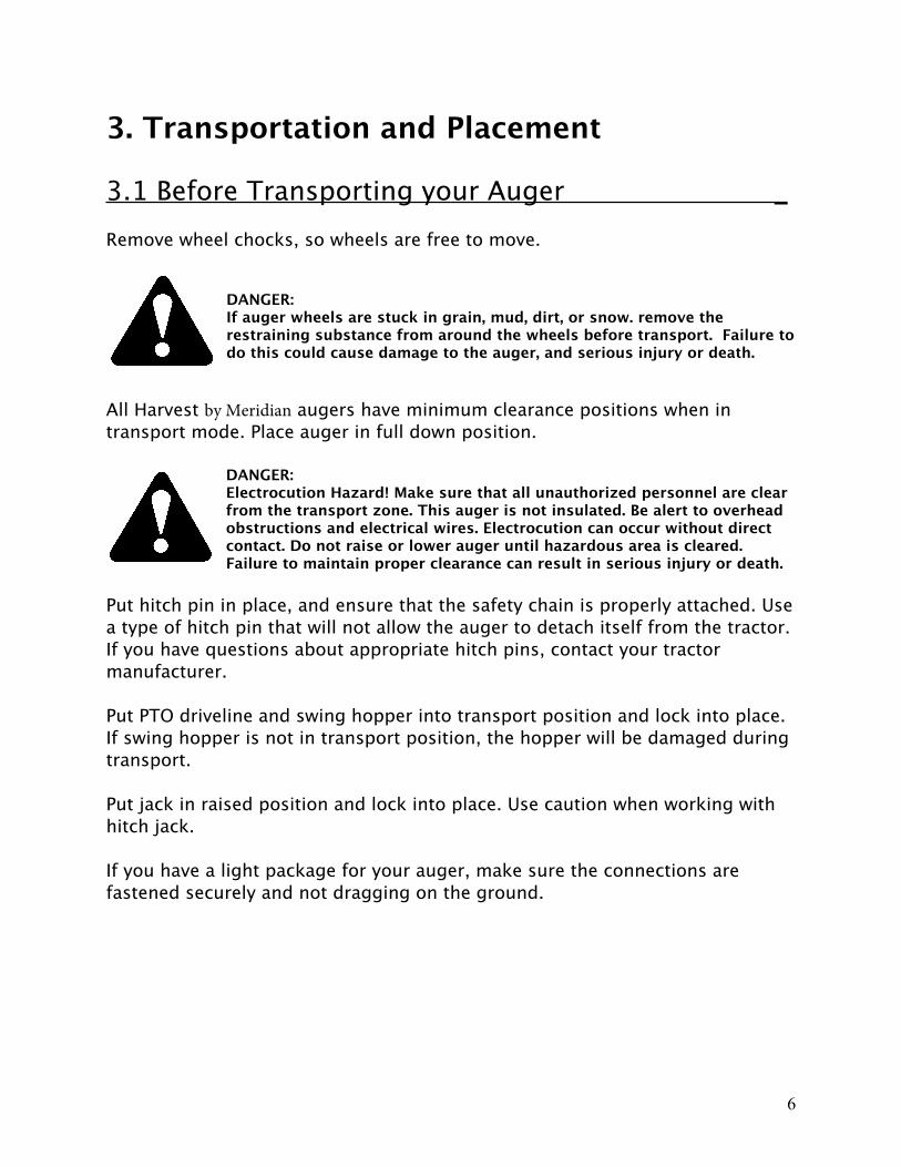
3.1 Before Transporting your Auger _Remove wheel chocks, so wheels are free to move.
DANGER:If auger wheels are stuck in grain, mud, dirt, or snow. remove the restraining substance from around the wheels before transport. Failure to do this could cause damage to the auger, and serious injury or death.
All Harvest by Meridian augers have minimum clearance positions when in transport mode. Place auger in full down position.
DANGER:Electrocution Hazard! Make sure that all unauthorized personnel are clear from the transport zone. This auger is not insulated. Be alert to overhead obstructions and electrical wires. Electrocution can occur without direct contact. Do not raise or lower auger until hazardous area is cleared. Failure to maintain proper clearance can result in serious injury or death.
Put hitch pin in place, and ensure that the safety chain is properly attached. Use a type of hitch pin that will not allow the auger to detach itself from the tractor. If you have questions about appropriate hitch pins, contact your tractor manufacturer.
Put PTO driveline and swing hopper into transport position and lock into place. If swing hopper is not in transport position, the hopper will be damaged during transport.
Put jack in raised position and lock into place. Use caution when working with hitch jack.
If you have a light package for your auger, make sure the connections are fastened securely and not dragging on the ground.
6

3.2 Transportation Procedure _Move auger with a tractor only. Never attempt to move by hand.
Under no condition should you allow riders on the auger or tractor.
Transport the auger no faster than 15 mph. When roads are rough or surfaces are uneven, slow down to ensure safe travel.
DANGER:Do not transport the auger on slopes greater than 20 degrees. This could cause the auger to tip, resulting in damage to the auger, and personal injury or death.
When visibility is reduced, please use caution and add extra lights to the auger. Consider using a pilot vehicle for safer travel.
Use extreme caution when turning or cornering with the auger in tow.
Check regulations with local authorities regarding auger transportation. Follow all over-width regulations. Equip auger with all necessary lighting, and use hazard warning flashers on your tractor, when required by law.
3.3 Placement of Auger _Before raising or lowering your auger, check that the area is clear of obstructions, children and unauthorized personnel.
DANGER:Electrocution Hazard! Make sure that all unauthorized personnel are clear from the transport zone. This auger is not insulated. Be alert to overhead obstructions and electrical wires. Electrocution can occur without direct contact. Do not raise or lower auger until hazardous area is cleared. Failure to maintain proper clearance can result in serious injury or death.
Ensure that your auger is on level ground that is free of debris.
DANGER:If ground is very uneven, auger can tip and cause damage to the equipment and personal injury or death.
7
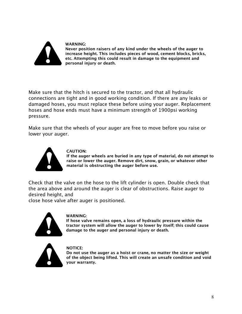
WARNING:Never position raisers of any kind under the wheels of the auger to increase height. This includes pieces of wood, cement blocks, bricks, etc. Attempting this could result in damage to the equipment and personal injury or death.
Make sure that the hitch is secured to the tractor, and that all hydraulic connections are tight and in good working condition. If there are any leaks or damaged hoses, you must replace these before using your auger. Replacement hoses and hose ends must have a minimum strength of 1900psi working pressure.
Make sure that the wheels of your auger are free to move before you raise or lower your auger.
CAUTION:If the auger wheels are buried in any type of material, do not attempt to raise or lower the auger. Remove dirt, snow, grain, or whatever other material is obstructing the auger before use.
Check that the valve on the hose to the lift cylinder is open. Double check that the area above and around the auger is clear of obstructions. Raise auger to desired height, and close hose valve after auger is positioned.
WARNING:If hose valve remains open, a loss of hydraulic pressure within the tractor system will allow the auger to lower by itself; this could cause damage to the auger and personal injury or death.
NOTICE:Do not use the auger as a hoist or crane, no matter the size or weight of the object being lifted. This will create an unsafe condition and void your warranty.
8
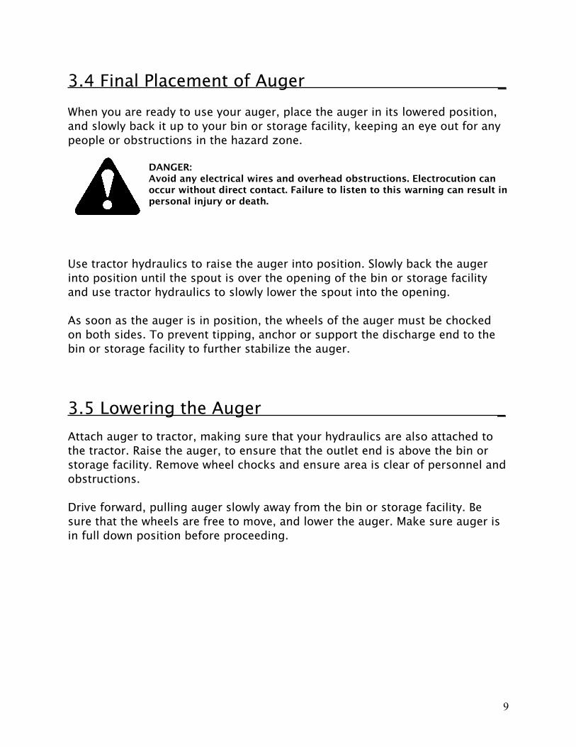
3.4 Final Placement of Auger _When you are ready to use your auger, place the auger in its lowered position, and slowly back it up to your bin or storage facility, keeping an eye out for any people or obstructions in the hazard zone.
DANGER:Avoid any electrical wires and overhead obstructions. Electrocution can occur without direct contact. Failure to listen to this warning can result in personal injury or death.
Use tractor hydraulics to raise the auger into position. Slowly back the auger into position until the spout is over the opening of the bin or storage facility and use tractor hydraulics to slowly lower the spout into the opening.
As soon as the auger is in position, the wheels of the auger must be chocked on both sides. To prevent tipping, anchor or support the discharge end to the bin or storage facility to further stabilize the auger.
3.5 Lowering the Auger _Attach auger to tractor, making sure that your hydraulics are also attached to the tractor. Raise the auger, to ensure that the outlet end is above the bin or storage facility. Remove wheel chocks and ensure area is clear of personnel and obstructions.
Drive forward, pulling auger slowly away from the bin or storage facility. Be sure that the wheels are free to move, and lower the auger. Make sure auger is in full down position before proceeding.
9
4. OperationWear protective gear at all times when operating auger, such as hard hats, protective shoes, eye protection, and gloves. Do not wear loose clothing, and be sure that hair is tied back.
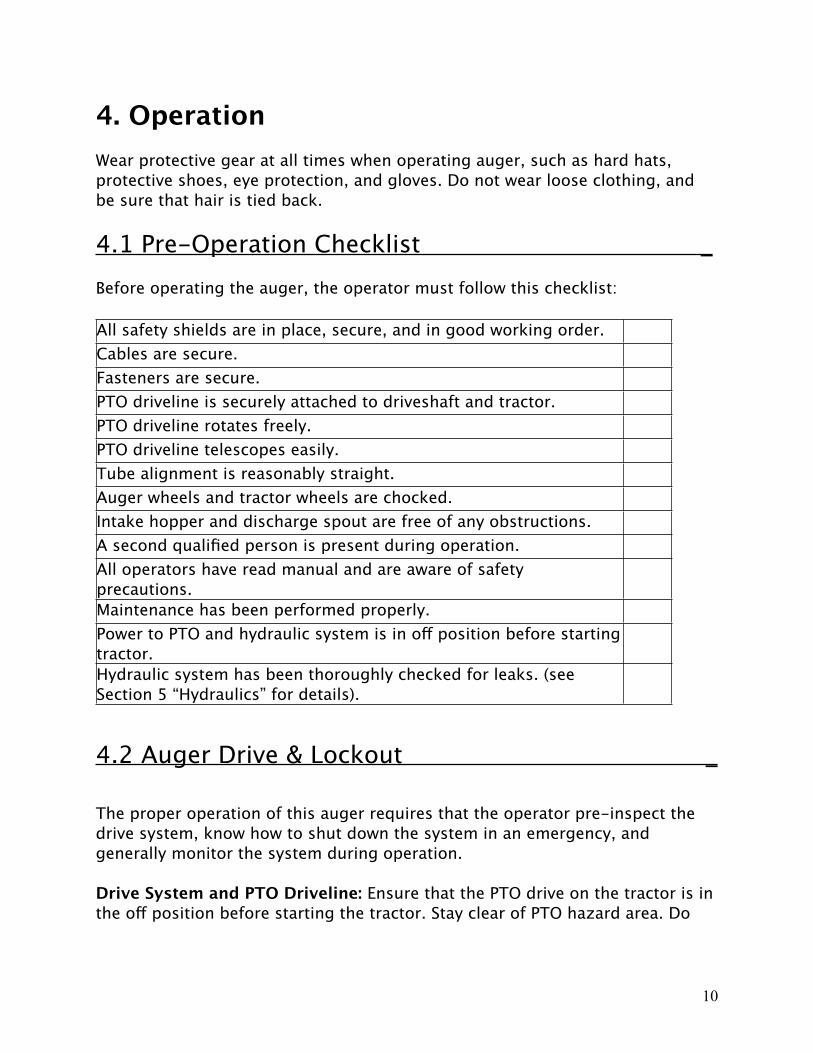
4.1 Pre-Operation Checklist _Before operating the auger, the operator must follow this checklist:
All safety shields are in place, secure, and in good working order. Cables are secure.Fasteners are secure.PTO driveline is securely attached to driveshaft and tractor.PTO driveline rotates freely.PTO driveline telescopes easily. Tube alignment is reasonably straight.Auger wheels and tractor wheels are chocked.Intake hopper and discharge spout are free of any obstructions.A second qualified person is present during operation.All operators have read manual and are aware of safety precautions.Maintenance has been performed properly.Power to PTO and hydraulic system is in off position before starting tractor.Hydraulic system has been thoroughly checked for leaks. (see Section 5 “Hydraulics” for details).
4.2 Auger Drive & Lockout _
The proper operation of this auger requires that the operator pre-inspect the drive system, know how to shut down the system in an emergency, and generally monitor the system during operation.
Drive System and PTO Driveline: Ensure that the PTO drive on the tractor is inthe off position before starting the tractor. Stay clear of PTO hazard area. Do
10
not exceed the maximum operation length of 34 inches of PTO driveline, or the maximum angularity of 30 degrees.
Lockout/Shutdown of PTO Driveline: Turn off engine. Remove ignition keyfrom tractor. If for some reason, you cannot remove the key, remove the PTO driveline from the tractor.
4.3 Start Up & Break In _DANGER:Electrocution Hazard! Make sure that all unauthorized personnel are clear from the operation zone. This auger is not insulated. Be alert to overhead obstructions and electrical wires. Electrocution can occur without direct contact. Do not raise or lower auger until hazardous area is cleared. Failure to maintain proper clearance can result in serious injury or death.
Have you completed the pre-operational checklist? If everything is satisfactory, prepare for a 30 minute operation at half speed to break in your auger. Double check that the intake hopper is properly positioned, and the PTO drive on the tractor is in the off position.
NOTICE:When starting the auger for the first time, be prepared for an emergency shutdown in case of excessive vibration or noise. The auger may run roughly until the tube is polished.
Start the tractor and idle at low RPM. Slowly engage the PTO driveline.
Gradually begin to feed grain into the intake hopper, bringing the speed of the PTO to 200 RPM. Do not over-feed the hopper on initial loads; keep the feed of the grain at half capacity. After the auger tube is polished and runs smoothly, proceed to unload at full speed (at but not to exceed 540 RPM for maximum efficiency).
Upon completion of initial run, slow down until the auger is empty of grain, and stop auger. Lock out the power source and conduct a complete inspection of the auger, following the pre-operation checklist. After the initial start up and inspection, the auger should be shut down and inspected at least three times during the first hours of operation. Once your auger is broken in, the pre-operation checklist should be part of the daily routine before you operate the auger.
11
4.4 Everyday Operation _
WARNING:When auger is in operation, keep your hands, clothing, and other objects away from intake hopper, drive chains, and all other parts of auger to avoid personal injury.
For normal auger operations, the following procedure and safety precautions are strongly recommended:
Complete the pre-operation checklist before using your auger.
Remember to ground motor before using auger if an electric motor is being used.
When using the auger, work with another trained operator present to monitor the operation and help with a shutdown in case of an emergency. Monitor the auger during operation for vibration and abnormal noises. If anything out of the ordinary is noted, shut down and lock out the auger, determine the source, and correct before continuing operation.
Keep the hopper full and running at 540 RPM for maximum capacity. Pour grain in the middle of hopper, closest to the tube for best results.
Run the auger only when moving material. Running the auger without grain moving through causes unnecessary wear.
4.5 Shutting Down the Auger _Empty the auger of all grain. Disengage the PTO drive. Shut down and lock out power.
WARNING:Never use your hands to clean out debris from auger. Rather, use a small shovel or other tool.
In the case where there has been an interruption or emergency shutdown, restart the auger as follows:
12

If auger is full of grain, do not restart at full speed. Engage PTO at low RPM and gradually increase power until normal operating speed is achieved.
CAUTION:Starting the auger under load may result in damage to the auger. Make sure there is no blockage.
4.6 Completion and Cleanup _At completion of operation, the auger needs to be moved into storage position. Make sure that the entire work area is clean, remove all supports and wheel chocks, move auger out of working position, and fully lower the auger (see lowering procedure below).
The proper steps for clean out of the auger are as follows:1) Disengage power source; lower the auger into transport position.2) Shut off tractor and lock out power.3) Move intake hopper into transport position and latch with safety chain.4) If necessary, clean out grain using small shovel or other tool.
WARNING:Do not leave auger in raised position when not in use. Auger could drop rapidly in case of hydraulic failure. High winds may also upset the auger. Because the hydraulic scissor lift is faster than a hand crank system, use extra caution and clear area of personnel before raising or lowering auger.
4.7 Lowering the Auger _Check that auger and hose couplers are securely attached to your tractor.
You may need to raise the auger discharge end up and out of bin or storage facility before proceeding.
Remove wheel chocks, and check that the area around and under the auger is clear of debris and unauthorized personnel. Wheels must be free to move when raising or lowering the auger.
Slowly pull away from bin or storage facility. As soon as you are clear, engage the hydraulics and lower the auger. Once valves are open, the auger lowers by
13
gravity. Rate of descent increases the closer the auger gets to the down position. Be cautious.
Transport auger only in fully lowered position.
5. Hydraulics5.1 General Information _Be sure that all safety precautions and proper operation procedures are fully understood before connecting the auger hydraulic hoses. Harvest by Meridian strongly recommends doing a daily visual check for damage to the hoses and connectors. Replace any damaged parts before operation.
WARNING:Wear proper face and hand protection when searching for hydraulic leaks. Fluid can escape under pressure, causing infection or toxic reaction on skin. See a doctor immediately if injured.
Escaping hydraulic fluid can be nearly invisible under high pressure. Use some type of backdrop when searching for leaks.
Harvest by Meridian augers have a velocity fuse for hydraulic safety. If the hydraulic line breaks, it locks the system. Our shut off valve is equipped with a flow restrictive orifice. After you have repaired the hydraulic hose, the system resets itself and is ready for operation.
There are various types of tractor hydraulic systems; the quick connect couplers are supplied by the owners. Please consult your tractor manual for the proper couplers.
Before you connect your hydraulic hoses, check that the quick connect couplers on the auger and tractor are clean and free of any dirt or debris; wiping them down with a cloth.
CAUTION:Dirt in the hydraulic system can damage the cylinder o-rings. This may cause leakage and possible system failure.
14
Do not disconnect the hydraulic coupler when the system is under pressure. Relieve all pressure and then disconnect.
5.2 Cylinder Hydraulics _
The testing done on Harvest by Meridian auger hydraulics was done using a pressure gauge with 3000psi maximum rating. This was used simply as a guide. The psi requirements for an individual auger may vary slightly.
Auger Size PSIH1064XT 10” x 64’ 1300H1074XT 10” x 74’ 1400H1084XT 10” x 84’ 1600H1364XT 13” x 64’ 1600H1374XT 13” x 74’ 1800H1384XT 13” x 84’ 1900
Have approximately four liters of hydraulic fluid in your system. Check that the valve on the hose to lift the cylinder is open. Start tractor and engage hydraulics. Raise the auger to desired height, and close hose valve. You must turn valve while the hydraulic system is pressurized; do not disconnect hydraulic couplers.
WARNING:If valve hose remains open, a loss of hydraulic pressure within the tractor system could allow the auger to lower unexpectedly, causing damage to the auger and personal injury.
To lower the auger, reconnect hose couplers to the tractor. Ensure that area is clear and wheels are free to move. Open the hose valve, start your tractor, and engage hydraulics. The auger is fully lowered when the tube is resting on the tube saddle.
NOTICE:After valves are opened, the auger lowers by gravity. As the auger nears the full down position, the rate of descent will increase.
15

6. Maintenance & StorageProper maintenance of auger will result in both a longer life of the auger and a safe and efficient operation.
6.1 General Maintenance _Always replace damaged or worn parts before using the auger. Use only replacement parts manufactured by Harvest by Meridian, Inc. Use of unauthorized parts will void the warranty of your auger. Contact your Harvest by Meridian dealer to order parts.
Harvest by Meridian augers are designed and tested for a safe, efficient operation. Do not modify the equipment in any way. Modification to the auger can create an unsafe working condition, affect the life of the equipment, and will void your warranty.
Before performing maintenance on your auger, shut down and lock out all power. Disconnect the PTO driveline from the tractor. Support the auger tube before attempting maintenance on the undercarriage. The auger should be in full down position before attempting maintenance.
After Maintenance is completed, replace and secure all safety shields, safety devices, service doors and cleanout covers.
See section 5, “Hydraulics” for information on maintenance of hydraulic hoses.
See section 7, “Appendix & Forms” for expanded lube information.
Truss Cables: Replace cables if frayed or damaged. Be sure clamps are secure.Adjust cables as needed to keep the auger tube reasonably straight.
Wheel Hubs: Repack hubs every two to three years to lengthen the life of thehubs.
Tire Pressure: Check tire pressure monthly. The recommended tire pressureshould be maintained at 40 to 45 psi.
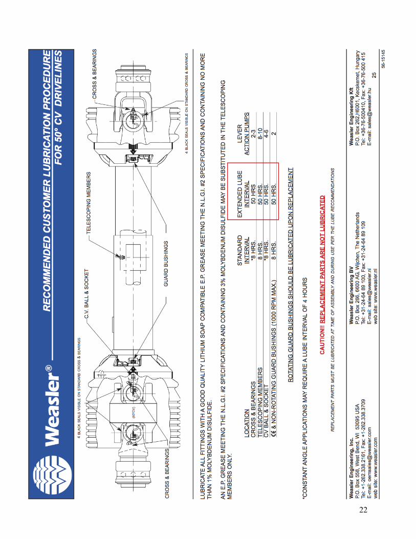
PTO Driveline: Lubricate both universal joints after every eight hours ofoperation. Lubricate the center portion of the driveline on a yearly basis. The first lube maintenance should be done in the first 16 to 24 hours of operation. Then follow a regular schedule of lubing.
16

Lube Recommendation: Lube cross and bearing every 8 hours of use. Lubetelescoping members yearly.
NOTICE:Replacement parts are not lubricated. When you receive these parts in, make sure to lubricate and tighten screws.
Mechanical Chain Drive: Keep drive chain tension adjusted to about ¼”deflection by loosening the four bolts on the lower bearing, then retightening. Oil the chain frequently enough to keep a film of oil on the chain. This must be done through the maintenance portal. Replace shield after maintenance.
Universal Joint: Remove PTO guard cover and lubricate grease fitting in the U-Joint every eight hours of use. Check PTO retain bolt and retighten if necessary.
6.2 Storage of Auger _Make sure that auger is in the full down position. Remove all residual material from the hopper and auger tubes. Touch up all scratches on the auger to prevent rusting.
Clean and re-lubricate spline on the PTO driveline. Cover with plastic bag to protect from weather, and place it in the transport latch.
Move auger to your storage area, park, and chock wheels.
Before using the auger after storage, replace any damaged parts or decals, remove plastic bag from PTO driveline and re-lubricate, and conduct general maintenance procedure.
17
18
19
20
21
22
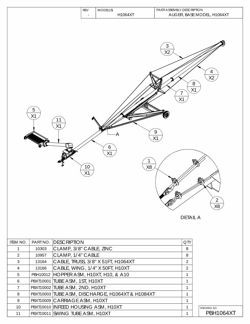
ITEM NO. PART NO. DESCRIPTION QTY1 10303 CLAMP, 3/8" CABLE, ZINC 82 10957 CLAMP, 1/4" CABLE 83 13164 CABLE, TRUSS, 3/8" X 51FT, H1064XT 24 13166 CABLE, WING, 1/4" X 50FT, H10XT 25 PBH10012 HOPPER ASM, H10XT, H10, & A10 16 PBXT10001 TUBE ASM, 1ST, H10XT 17 PBXT10002 TUBE ASM, 2ND, H10XT 18 PBXT10003 TUBE ASM, DISCHARGE, H1064XT & H1084XT 19 PBXT10009 CARRIAGE ASM, H10XT 1
10 PBXT10010 INFEED HOUSING ASM, H10XT 111 PBXT10011 SWING TUBE ASM, H10XT 1
REV MODEL(S)AUGER, BASE MODEL, H1064XT
PBH1064XTDRAWING NO.
H1064XTPART/ASSEMBLY DESCRIPTION
-
X2
X15
X111
X16
X110
X19
X17 X1
8X24
3
A
2X8
DETAIL A
1X8

B
1
20
15
X410
X4
13
X46
C
8
11
4
X2
7
9
X2717
X27
23
24
X4
19
X2
16
16
26
25
X2
18
X9
2
X9
27
17
28
NOTE: A10XX SERIES AUGERS USE SWING HOPPER WELDMENT #30722, REMAINING PARTS AREAS SHOWN
Detail B
14
14
14
DRAWING NO.
PBH10012
7
4
X2
Detail C
2
X8
22
3
X8
18
X820
5
5
5
21
2022
16
X3
REV
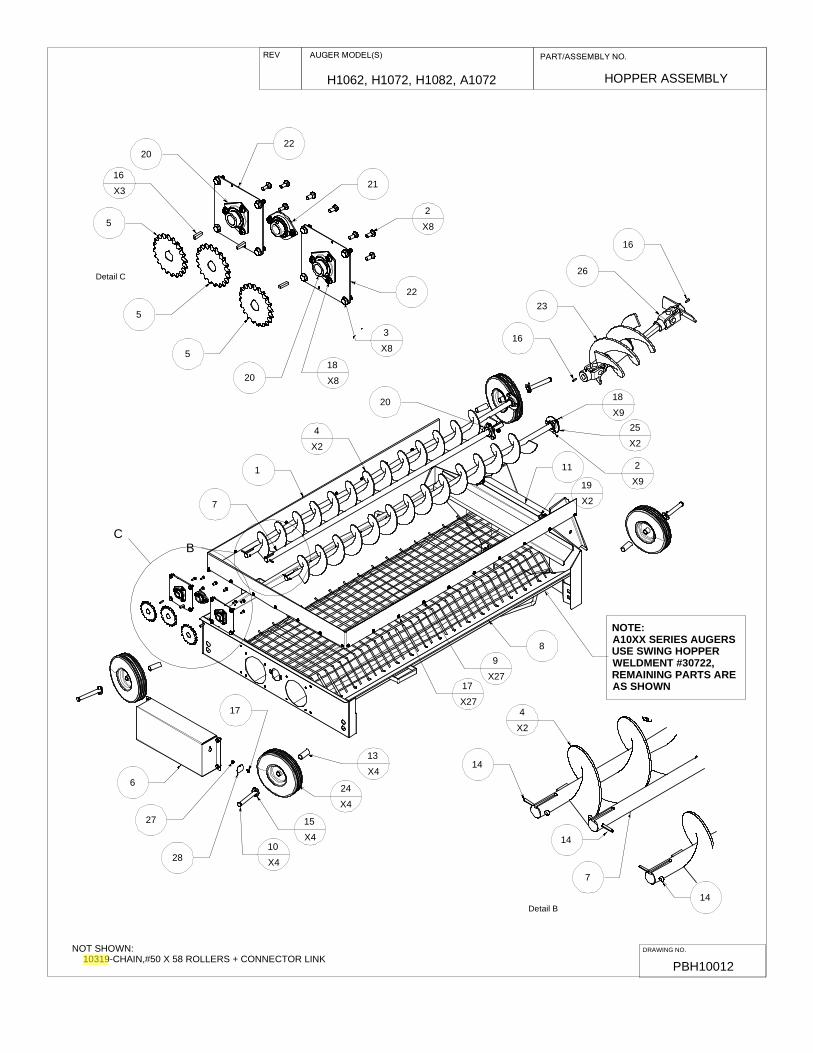
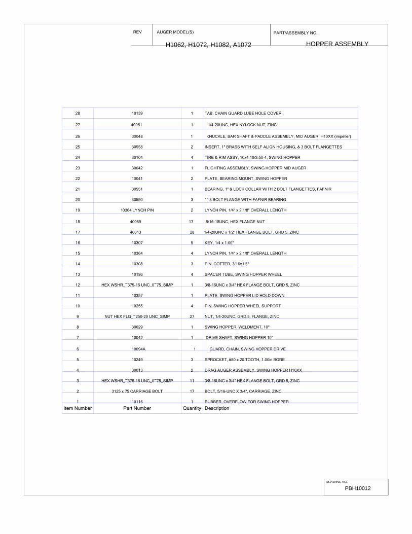
HOPPER ASSEMBLY
AUGER MODEL(S) PART/ASSEMBLY NO.
H1062, H1072, H1082, A1072
NOT SHOWN: 10319-CHAIN,#50 X 58 ROLLERS + CONNECTOR LINK
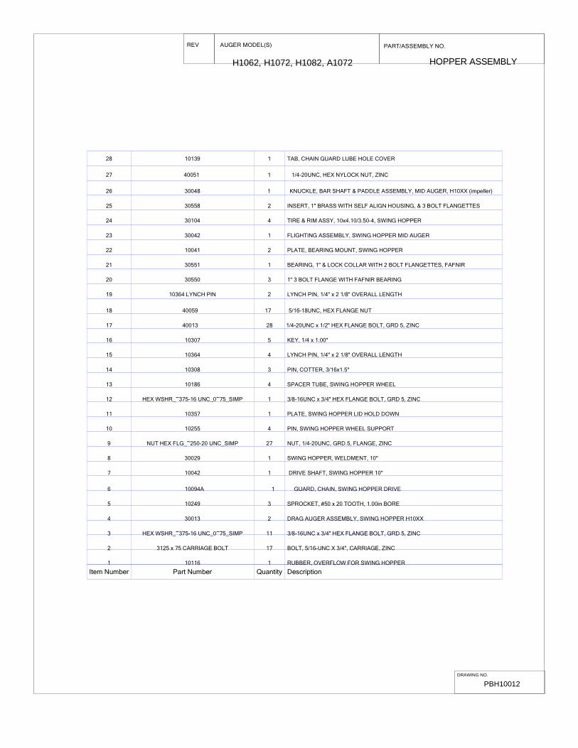
Item Number Part Number Quantity Description
28 10139 1 TAB, CHAIN GUARD LUBE HOLE COVER
27 40051 1 1/4-20UNC, HEX NYLOCK NUT, ZINC
26 30048 1 KNUCKLE, BAR SHAFT & PADDLE ASSEMBLY, MID AUGER, H10XX (impeller)
25 30558 2 INSERT, 1" BRASS WITH SELF ALIGN HOUSING, & 3 BOLT FLANGETTES
24 30104 4 TIRE & RIM ASSY, 10x4.10/3.50-4, SWING HOPPER
23 30042 1 FLIGHTING ASSEMBLY, SWING HOPPER MID AUGER
22 10041 2 PLATE, BEARING MOUNT, SWING HOPPER
21 30551 1 BEARING, 1" & LOCK COLLAR WITH 2 BOLT FLANGETTES, FAFNIR
20 30550 3 1" 3 BOLT FLANGE WITH FAFNIR BEARING
19 10364 LYNCH PIN 2 LYNCH PIN, 1/4" x 2 1/8" OVERALL LENGTH
18 40059 17 5/16-18UNC, HEX FLANGE NUT
17 40013 28 1/4-20UNC x 1/2" HEX FLANGE BOLT, GRD 5, ZINC
16 10307 5 KEY, 1/4 x 1.00"
15 10364 4 LYNCH PIN, 1/4" x 2 1/8" OVERALL LENGTH
14 10308 3 PIN, COTTER, 3/16x1.5"
13 10186 4 SPACER TUBE, SWING HOPPER WHEEL
12 HEX WSHR_~375-16 UNC_0~75_SIMP 1 3/8-16UNC x 3/4" HEX FLANGE BOLT, GRD 5, ZINC
11 10357 1 PLATE, SWING HOPPER LID HOLD DOWN
10 10255 4 PIN, SWING HOPPER WHEEL SUPPORT
9 NUT HEX FLG_~250-20 UNC_SIMP 27 NUT, 1/4-20UNC, GRD.5, FLANGE, ZINC
8 30029 1 SWING HOPPER, WELDMENT, 10"
7 10042 1 DRIVE SHAFT, SWING HOPPER 10"
6 10094A 1 GUARD, CHAIN, SWING HOPPER DRIVE
5 10249 3 SPROCKET, #50 x 20 TOOTH, 1.00in BORE
4 30013 2 DRAG AUGER ASSEMBLY, SWING HOPPER H10XX
3 HEX WSHR_~375-16 UNC_0~75_SIMP 11 3/8-16UNC x 3/4" HEX FLANGE BOLT, GRD 5, ZINC
2 3125 x 75 CARRIAGE BOLT 17 BOLT, 5/16-UNC X 3/4", CARRIAGE, ZINC
1 10116 1 RUBBER, OVERFLOW FOR SWING HOPPER
REV PART/ASSEMBLY NO.
HOPPER ASSEMBLYH1062, H1072, H1082, A1072
AUGER MODEL(S)
DRAWING NO.
PBH10012

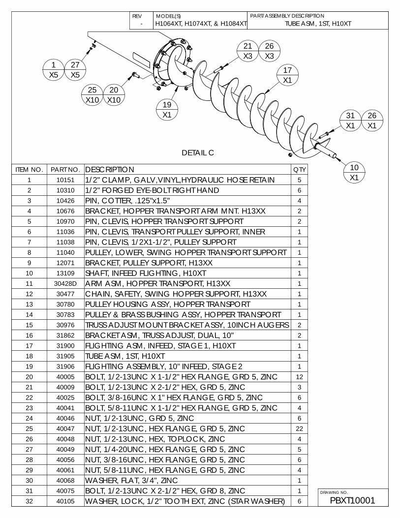
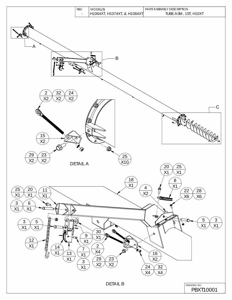
TUBE ASM, 1ST, H10XT
PBXT10001
PART/ASSEMBLY DESCRIPTIONREV MODEL(S)
DRAWING NO.
H1064XT, H1074XT, & H1084XT-
B
A
C
X2242
15
DETAIL A X1023
X2
X2
X2
X232
2529X2
11X1 X1
13
9
DETAIL B
X1X163
X1
X125 20
X13 5
3X1
7X114
X1
X130
X42
23 X2X2X2
1629
X43224X4
X15
X120
X122X2
8
28X6
X1
X6
4X1
3
X118
X1
25
X112X1
PART/ASSEMBLY DESCRIPTIONREV MODEL(S)
DRAWING NO.
TUBE ASM, 1ST, H10XT
PBXT10001
H1064XT, H1074XT, & H1084XT-
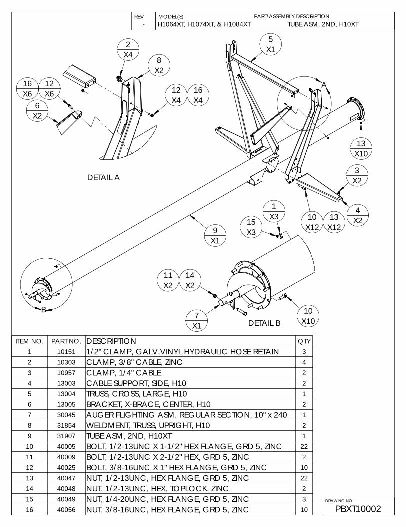
ITEM NO. PART NO. DESCRIPTION QTY1 10151 1/2" CLAMP, GALV,VINYL,HYDRAULIC HOSE RETAIN 52 10310 1/2" FORGED EYE-BOLT RIGHT HAND 63 10426 PIN, COTTER, .125"x1.5" 44 10676 BRACKET, HOPPER TRANSPORT ARM MNT. H13XX 25 10970 PIN, CLEVIS, HOPPER TRANSPORT SUPPORT 26 11036 PIN, CLEVIS, TRANSPORT PULLEY SUPPORT, INNER 17 11038 PIN, CLEVIS, 1/2X1-1/2", PULLEY SUPPORT 18 11040 PULLEY, LOWER, SWING HOPPER TRANSPORT SUPPORT 19 12071 BRACKET, PULLEY SUPPORT, H13XX 1
10 13109 SHAFT, INFEED FLIGHTING, H10XT 111 30428D ARM ASM, HOPPER TRANSPORT, H13XX 112 30477 CHAIN, SAFETY, SWING HOPPER SUPPORT, H13XX 113 30780 PULLEY HOUSING ASSY, HOPPER TRANSPORT 114 30783 PULLEY & BRASS BUSHING ASSY, HOPPER TRANSPORT 115 30976 TRUSS ADJUST MOUNT BRACKET ASSY, 10INCH AUGERS 216 31862 BRACKET ASM, TRUSS ADJUST, DUAL, 10" 217 31900 FLIGHTING ASM, INFEED, STAGE 1, H10XT 118 31905 TUBE ASM, 1ST, H10XT 119 31906 FLIGHTING ASSEMBLY, 10" INFEED, STAGE 2 120 40005 BOLT, 1/2-13UNC X 1-1/2" HEX FLANGE, GRD 5, ZINC 1221 40009 BOLT, 1/2-13UNC X 2-1/2" HEX, GRD 5, ZINC 322 40025 BOLT, 3/8-16UNC X 1" HEX FLANGE, GRD 5, ZINC 623 40041 BOLT, 5/8-11UNC X 1-1/2" HEX FLANGE, GRD 5, ZINC 424 40046 NUT, 1/2-13UNC, GRD 5, ZINC 625 40047 NUT, 1/2-13UNC, HEX FLANGE, GRD 5, ZINC 2226 40048 NUT, 1/2-13UNC, HEX, TOPLOCK, ZINC 427 40049 NUT, 1/4-20UNC, HEX FLANGE, GRD 5, ZINC 528 40056 NUT, 3/8-16UNC, HEX FLANGE, GRD 5, ZINC 629 40061 NUT, 5/8-11UNC, HEX FLANGE, GRD 5, ZINC 430 40068 WASHER, FLAT, 3/4", ZINC 131 40075 BOLT, 1/2-13UNC X 2-1/2" HEX, GRD 8, ZINC 132 40105 WASHER, LOCK, 1/2" TOOTH EXT, ZINC (STAR WASHER) 6
17X1
DETAIL C
X131
X321
X51 27
X5
X10X1025
X326
26
20
X1X119
10X1
1411X2 X2
X10X1 DETAIL B7
15X3
10
1X3
9
A
X1
X15
X121310
X12X24
X23
13X10
B
MODEL(S) PART/ASSEMBLY DESCRIPTIONREV
DRAWING NO.
TUBE ASM, 2ND, H10XT
PBXT10002
H1064XT, H1074XT, & H1084XT-
ITEM NO. PART NO. DESCRIPTION QTY1 10151 1/2" CLAMP, GALV,VINYL,HYDRAULIC HOSE RETAIN 32 10303 CLAMP, 3/8" CABLE, ZINC 43 10957 CLAMP, 1/4" CABLE 24 13003 CABLE SUPPORT, SIDE, H10 25 13004 TRUSS, CROSS, LARGE, H10 16 13005 BRACKET, X-BRACE, CENTER, H10 27 30045 AUGER FLIGHTING ASM, REGULAR SECTION, 10" x 240 18 31854 WELDMENT, TRUSS, UPRIGHT, H10 29 31907 TUBE ASM, 2ND, H10XT 1
10 40005 BOLT, 1/2-13UNC X 1-1/2" HEX FLANGE, GRD 5, ZINC 2211 40009 BOLT, 1/2-13UNC X 2-1/2" HEX, GRD 5, ZINC 212 40025 BOLT, 3/8-16UNC X 1" HEX FLANGE, GRD 5, ZINC 1013 40047 NUT, 1/2-13UNC, HEX FLANGE, GRD 5, ZINC 2214 40048 NUT, 1/2-13UNC, HEX, TOPLOCK, ZINC 215 40049 NUT, 1/4-20UNC, HEX FLANGE, GRD 5, ZINC 316 40056 NUT, 3/8-16UNC, HEX FLANGE, GRD 5, ZINC 10
X6X416
1612X6
X2
8
DETAIL A
12
6
X2
X4
2X4
13X2
X109
10X2
11 14X2
X21
X22
X1012
X1
9
16
X10
X18
X16
4X5
15
X2X5
X16
X2
5
3X2
7X1
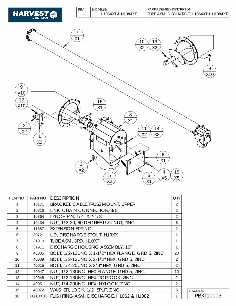
ITEM NO. PART NO. DESCRIPTION QTY1 10171 BRACKET, CABLE TRUSS MOUNT, UPPER 22 10316 LINK, CHAIN CONNECTOR, 3/8" 23 10364 LYNCH PIN, 1/4" X 2-1/8" 24 10434 NUT, 1/2-20, 60 DEGREE LUG NUT, ZINC 55 11357 EXTENSION SPRING 26 30721 LID, DISCHARGE SPOUT, H10XX 17 31910 TUBE ASM, 3RD, H10XT 18 31911 DISCHARGE HOUSING ASSEMBLY, 10" 19 40005 BOLT, 1/2-13UNC X 1-1/2" HEX FLANGE, GRD 5, ZINC 20
10 40009 BOLT, 1/2-13UNC X 2-1/2" HEX, GRD 5, ZINC 211 40015 BOLT, 1/4-20UNC X 3/4" HEX, GRD 5, ZINC 212 40047 NUT, 1/2-13UNC, HEX FLANGE, GRD 5, ZINC 1013 40048 NUT, 1/2-13UNC, HEX, TOPLOCK, ZINC 214 40051 NUT, 1/4-20UNC, HEX, NYLOCK, ZINC 215 40072 WASHER, LOCK, 1/2" SPLIT, ZINC 516 PBH10016 FLIGHTING ASM, DISCHARGE, H1062 & H1082 1
DRAWING NO.
TUBE ASM, DISCHARGE, H1064XT & H1084XT
PBXT10003
H1064XT & H1084XTPART/ASSEMBLY DESCRIPTIONREV MODEL(S)
-
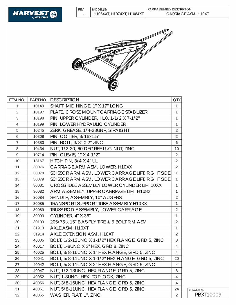
CARRIAGE ASM, H10XT
PBXT10009
H1064XT, H1074XT, H1084XTPART/ASSEMBLY DESCRIPTIONREV MODEL(S)
DRAWING NO.
-
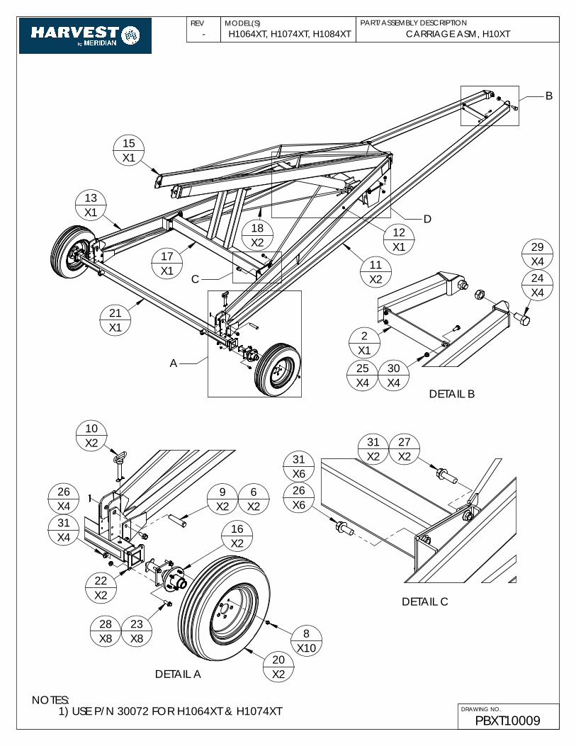
NOTES:1) USE P/N 30072 FOR H1064XT & H1074XT
B
X218
C11X2
X1
A
13
15X1
X117X1
12
21X1
D
26
31X4
X210
DETAIL A
8X10
20X2
X82328
X8
16X2
X2 X29 6
X4
22X2
X1
X4X425
DETAIL B
24X4
30
2
29X4
X6
X2X631
DETAIL C
27
26
31X2
X2
DETAIL EX25
X27X2
32X11
27 31X2
E
CARRIAGE ASM, H10XT
PBXT10009
H1064XT, H1074XT, H1084XTPART/ASSEMBLY DESCRIPTIONREV MODEL(S)
DRAWING NO.
-
26
X1
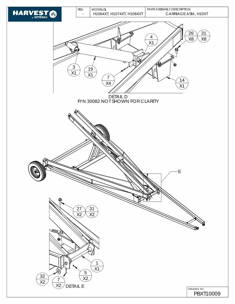
DETAIL DP/N 30082 NOT SHOWN FOR CLARITY
X8
7X119
X13
X4
X14
14
31X8

PBXT10009
H1064XT, H1074XT, H1084XTPART/ASSEMBLY DESCRIPTIONREV MODEL(S)
DRAWING NO.
CARRIAGE ASM, H10XT-
ITEM NO. PART NO. DESCRIPTION QTY1 10149 SHAFT, MID HINGE, 1" X 17" LONG 12 10197 PLATE, CROSS MOUNT CARRIAGE STABILIZER 13 10198 PIN, UPPER CYLINDER, H10, 1-1/2 X 7-1/2" 14 10199 PIN, LOWER HYDRAULIC CYLINDER 15 10245 ZERK, GREASE, 1/4-28UNF, STRAIGHT 26 10308 PIN, COTTER, 3/16x1.5" 27 10383 PIN, ROLL, 3/8" X 2" ZINC 68 10434 NUT, 1/2-20, 60 DEGREE LUG NUT, ZINC 109 10714 PIN, CLEVIS, 1" X 4-1/2" 2
10 13167 HITCH PIN, 3/4 X 4" UL 211 30076 CARRIAGE ARM ASM, LOWER, H10XX 212 30078 SCISSOR ARM ASM, LOWER CARRIAGE LIFT, RIGHT SIDE 113 30079 SCISSOR ARM ASM, LOWER CARRIAGE LIFT, RIGHT SIDE 114 30081 CROSS TUBE ASSEMBLY,LOWER CYLINDER LIFT,10XX 115 30082 ARM ASSEMBLY, UPPER CARRIAGE LIFT, H1082 116 30084 SPINDLE, ASSEMBLY, 10" AUGERS 217 30085 TRANSPORT SUPPORT TUBE ASSEMBLY H10XX 118 30089 TRUSS ROD ASSEMBLY, LOWER CARRIAGE 219 30093 CYLINDER, 4" X 36" 120 30103 205/75 x 15" BIAS PLY TIRE & 5 BOLT RIM ASM 221 31913 AXLE ASM, H10XT 122 31914 AXLE EXTENSION ASM, H10XT 223 40005 BOLT, 1/2-13UNC X 1-1/2" HEX FLANGE, GRD 5, ZINC 824 40017 BOLT, 1-8UNC X 2" HEX, GRD 8, ZINC 425 40025 BOLT, 3/8-16UNC X 1" HEX FLANGE, GRD 5, ZINC 426 40041 BOLT, 5/8-11UNC X 1-1/2" HEX FLANGE, GRD 5, ZINC 2027 40042 BOLT, 5/8-11UNC X 2" HEX FLANGE, GRD 5, ZINC 428 40047 NUT, 1/2-13UNC, HEX FLANGE, GRD 5, ZINC 829 40052 NUT, 1-8UNC, HEX, TOPLOCK, ZINC 430 40056 NUT, 3/8-16UNC, HEX FLANGE, GRD 5, ZINC 431 40061 NUT, 5/8-11UNC, HEX FLANGE, GRD 5, ZINC 2432 40065 WASHER, FLAT, 1", ZINC 2
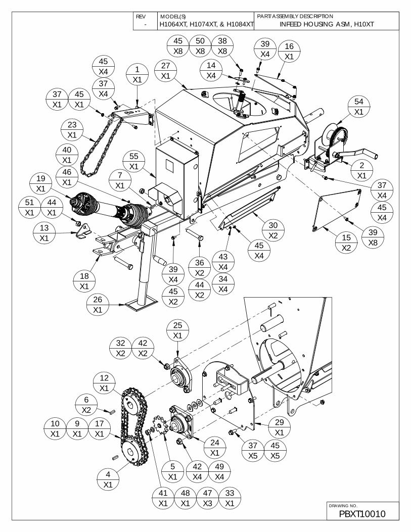
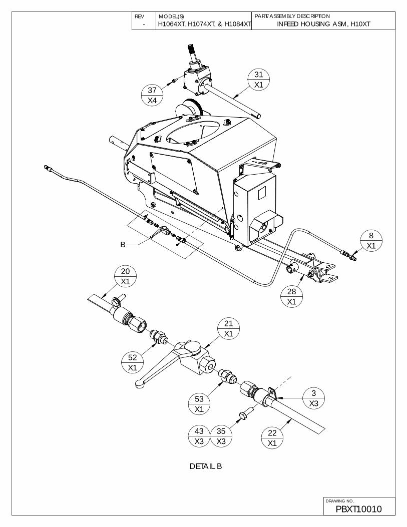
INFEED HOUSING ASM, H10XT
PBXT10010
H1064XT, H1074XT, & H1084XTPART/ASSEMBLY DESCRIPTIONREV MODEL(S)
DRAWING NO.
-
37X4
X2
39X4
16X1
38X8
14X4
45X1
X437
45X4 1
X1
X123
37X1
44X1
X113
51X1
19X1
18X1
26X1
54X1
39X8
30X2
45X4
36 X4
X4
X234
43
44X2
27X1
7X1X1
X146
40
X1
X2
55
X4
X8
45
50
39
45X8
2X1
15
45X4
X125
X16
12
X2
X1
X1X1910 17
X1
X1 X148
X347 3341
X1
X15
X44942X4
X124
X54537X5
X232 42X2
4
29X1
PART/ASSEMBLY DESCRIPTIONREV MODEL(S)
DRAWING NO.
INFEED HOUSING ASM, H10XT
PBXT10010
H1064XT, H1074XT, & H1084XT-
37X4
31X1
8X1
28X1
B
X1
DETAIL B
X335
X33
X122
X121
X153
X152
20
43X3

PART/ASSEMBLY DESCRIPTIONREV MODEL(S)
DRAWING NO.
PBXT10010
-
ITEM NO. PART NO. DESCRIPTION QTY1 10100A BRACKET, PTO SUPPORT, H10XX 12 10131B BRACKET, WINCH MOUNT, BOLT ON 13 10151 1/2" CLAMP, GALV,VINYL,HYDRAULIC HOSE RETAIN 34 10248 SPROCKET, #60, 20 TOOTH, 1-1/4" BORE 15 10300 SPROCKET, IDLER, #60, 11 TOOTH, 1/2" BORE 16 10307 KEY, 1/4 X 1" 27 10309 KEY, 1/4" X 1-1/2" 18 10324 1/2 NPT MALE TIP, 1/2" BODYSIZE (8010-4) (PIONEER) 19 10553 CONNECTOR LINK, #60 ROLLER CHAIN 1
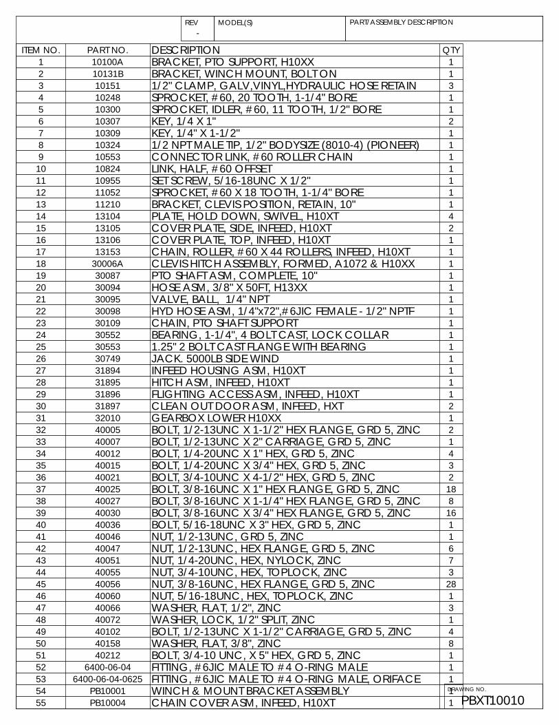
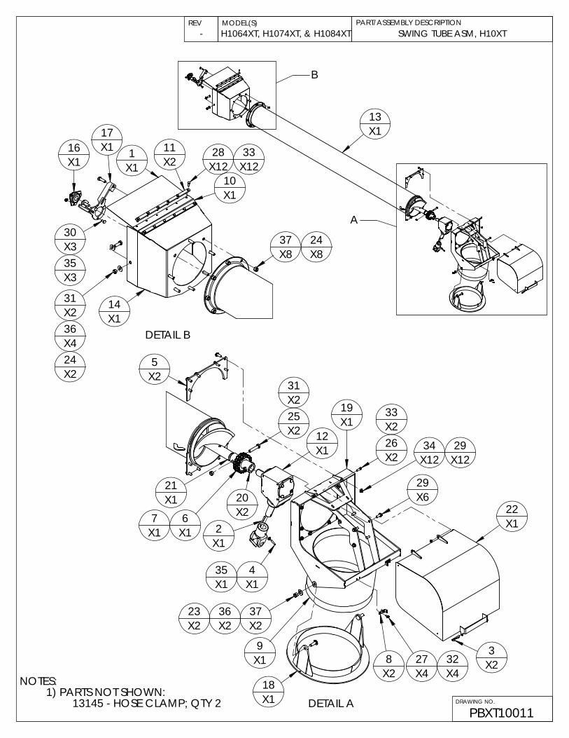
10 10824 LINK, HALF, #60 OFFSET 111 10955 SET SCREW, 5/16-18UNC X 1/2" 112 11052 SPROCKET, #60 X 18 TOOTH, 1-1/4" BORE 113 11210 BRACKET, CLEVIS POSITION, RETAIN, 10" 114 13104 PLATE, HOLD DOWN, SWIVEL, H10XT 415 13105 COVER PLATE, SIDE, INFEED, H10XT 216 13106 COVER PLATE, TOP, INFEED, H10XT 117 13153 CHAIN, ROLLER, #60 X 44 ROLLERS, INFEED, H10XT 118 30006A CLEVIS HITCH ASSEMBLY, FORMED, A1072 & H10XX 119 30087 PTO SHAFT ASM, COMPLETE, 10" 120 30094 HOSE ASM, 3/8" X 50FT, H13XX 121 30095 VALVE, BALL, 1/4" NPT 122 30098 HYD HOSE ASM, 1/4"x72",#6JIC FEMALE - 1/2" NPTF 123 30109 CHAIN, PTO SHAFT SUPPORT 124 30552 BEARING, 1-1/4", 4 BOLT CAST, LOCK COLLAR 125 30553 1.25" 2 BOLT CAST FLANGE WITH BEARING 126 30749 JACK. 5000LB SIDE WIND 127 31894 INFEED HOUSING ASM, H10XT 128 31895 HITCH ASM, INFEED, H10XT 129 31896 FLIGHTING ACCESS ASM, INFEED, H10XT 130 31897 CLEAN OUT DOOR ASM, INFEED, HXT 231 32010 GEARBOX LOWER H10XX 132 40005 BOLT, 1/2-13UNC X 1-1/2" HEX FLANGE, GRD 5, ZINC 233 40007 BOLT, 1/2-13UNC X 2" CARRIAGE, GRD 5, ZINC 134 40012 BOLT, 1/4-20UNC X 1" HEX, GRD 5, ZINC 435 40015 BOLT, 1/4-20UNC X 3/4" HEX, GRD 5, ZINC 336 40021 BOLT, 3/4-10UNC X 4-1/2" HEX, GRD 5, ZINC 237 40025 BOLT, 3/8-16UNC X 1" HEX FLANGE, GRD 5, ZINC 1838 40027 BOLT, 3/8-16UNC X 1-1/4" HEX FLANGE, GRD 5, ZINC 839 40030 BOLT, 3/8-16UNC X 3/4" HEX FLANGE, GRD 5, ZINC 1640 40036 BOLT, 5/16-18UNC X 3" HEX, GRD 5, ZINC 141 40046 NUT, 1/2-13UNC, GRD 5, ZINC 142 40047 NUT, 1/2-13UNC, HEX FLANGE, GRD 5, ZINC 643 40051 NUT, 1/4-20UNC, HEX, NYLOCK, ZINC 744 40055 NUT, 3/4-10UNC, HEX, TOPLOCK, ZINC 345 40056 NUT, 3/8-16UNC, HEX FLANGE, GRD 5, ZINC 2846 40060 NUT, 5/16-18UNC, HEX, TOPLOCK, ZINC 147 40066 WASHER, FLAT, 1/2", ZINC 348 40072 WASHER, LOCK, 1/2" SPLIT, ZINC 149 40102 BOLT, 1/2-13UNC X 1-1/2" CARRIAGE, GRD 5, ZINC 450 40158 WASHER, FLAT, 3/8", ZINC 851 40212 BOLT, 3/4-10 UNC, X 5" HEX, GRD 5, ZINC 152 6400-06-04 FITTING, #6JIC MALE TO #4 O-RING MALE 153 6400-06-04-0625 FITTING, #6JIC MALE TO #4 O-RING MALE, ORIFACE 154 PB10001 WINCH & MOUNT BRACKET ASSEMBLY 155 PB10004 CHAIN COVER ASM, INFEED, H10XT 1

NOTES:1) PARTS NOT SHOWN:
13145 - HOSE CLAMP; QTY 2PBXT10011
H1064XT, H1074XT, & H1084XTPART/ASSEMBLY DESCRIPTIONREV MODEL(S)
DRAWING NO.
SWING TUBE ASM, H10XT-
A
13X1
B
24X8
36
X1
DETAIL BX4
X1228 33
X1211X2
10X1
31X2
14X1
16X1
X330
35X3
1X1
17
X837
24X2
23 37X2
X23
DETAIL A
5X2
26X2
19X1
29X6
X1234 29
X12
20X2
X167
X1
8X2 X4
27 32X4
22X1
18X1
9X1
X1X1435
X225
31X2
12X1
X1
X2
2
X2X2
33
36
21X1

PART/ASSEMBLY DESCRIPTIONREV MODEL(S)
DRAWING NO.
PBXT10011
-
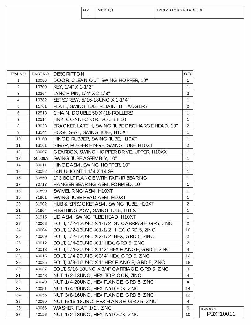
ITEM NO. PART NO. DESCRIPTION QTY1 10056 DOOR, CLEAN OUT, SWING HOPPER, 10" 12 10309 KEY, 1/4" X 1-1/2" 13 10364 LYNCH PIN, 1/4" X 2-1/8" 24 10382 SET SCREW, 5/16-18UNC X 1-1/4" 15 11761 PLATE, SWING TUBE RETAIN, 10” AUGERS 26 12513 CHAIN, DOUBLE 50 X (18 ROLLERS) 17 12514 LINK, CONNECTOR, DOUBLE 50 18 13033 BRACKET, LATCH, SWING TUBE DISCHARGE HEAD, 10" 29 13144 HOSE, SEAL, SWING TUBE, H10XT 1
10 13160 HINGE, RUBBER, SWING TUBE, H10XT 111 13161 STRAP, RUBBER HINGE, SWING TUBE, H10XT 212 30007 GEARBOX, SWING HOPPER DRIVE, UPPER, H10XX 113 30009A SWING TUBE ASSEMBLY, 10" 114 30011 HINGE ASM, SWING HOPPER, 10" 115 30092 14N U-JOINT 1 1/4 X 14 SP 116 30550 1" 3 BOLT FLANGE WITH FAFNIR BEARING 117 30718 HANGER BEARING ASM, FORMED, 10" 118 31899 SWIVEL RING ASM, H10XT 119 31901 SWING TUBE HEAD ASM, H10XT 120 31902 HUB & SPROCKET ASM, SWING TUBE, H10XT 221 31904 FLIGHTING ASM, SWING TUBE, H10XT 122 31915 LID ASM, SWING TUBE HEAD, H10XT 123 40003 BOLT, 1/2-13UNC X 1-1/2 SN CARRIAGE, GR5, ZINC 224 40004 BOLT, 1/2-13UNC X 1-1/2" HEX, GRD 5, ZINC 1025 40009 BOLT, 1/2-13UNC X 2-1/2" HEX, GRD 5, ZINC 226 40012 BOLT, 1/4-20UNC X 1" HEX, GRD 5, ZINC 227 40013 BOLT, 1/4-20UNC X 1/2" HEX FLANGE, GRD 5, ZINC 428 40015 BOLT, 1/4-20UNC X 3/4" HEX, GRD 5, ZINC 1229 40025 BOLT, 3/8-16UNC X 1" HEX FLANGE, GRD 5, ZINC 1830 40037 BOLT, 5/16-18UNC X 3/4" CARRIAGE, GRD 5, ZINC 331 40048 NUT, 1/2-13UNC, HEX, TOPLOCK, ZINC 432 40049 NUT, 1/4-20UNC, HEX FLANGE, GRD 5, ZINC 433 40051 NUT, 1/4-20UNC, HEX, NYLOCK, ZINC 1434 40056 NUT, 3/8-16UNC, HEX FLANGE, GRD 5, ZINC 1235 40059 NUT, 5/16-18UNC, HEX FLANGE, GRD 5, ZINC 436 40066 WASHER, FLAT, 1/2", ZINC 637 40126 NUT, 1/2-13UNC, HEX, NYLOCK, ZINC 10
AX113
X16
X17
X112
X111
X18
X19 X2
5
X23
X24
10X1
2X8
DETAIL A
1X16
DRAWING NO.
H1074XT
PBH1074XT
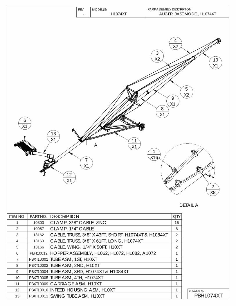
PART/ASSEMBLY DESCRIPTIONREV MODEL(S)AUGER, BASE MODEL, H1074XT-
ITEM NO. PART NO. DESCRIPTION QTY1 10303 CLAMP, 3/8" CABLE, ZINC 162 10957 CLAMP, 1/4" CABLE 83 13162 CABLE, TRUSS, 3/8" X 43FT, SHORT, H1074XT & H1084XT 24 13163 CABLE, TRUSS, 3/8" X 61FT, LONG, H1074XT 25 13166 CABLE, WING, 1/4" X 50FT, H10XT 26 PBH10012 HOPPER ASSEMBLY, H1062, H1072, H1082, A1072 17 PBXT10001 TUBE ASM, 1ST, H10XT 18 PBXT10002 TUBE ASM, 2ND, H10XT 19 PBXT10004 TUBE ASM, 3RD, H1074XT & H1084XT 1
10 PBXT10005 TUBE ASM, 4TH, H1074XT 111 PBXT10009 CARRIAGE ASM, H10XT 112 PBXT10010 INFEED HOUSING ASM, H10XT 113 PBXT10011 SWING TUBE ASM, H10XT 1
B
1
20
15
X410
X4
13
X46
C
8
11
4
X2
7
9
X2717
X27
23
24
X4
19
X2
16
16
26
25
X2
18
X9
2
X9
27
17
28
NOTE: A10XX SERIES AUGERS USE SWING HOPPER WELDMENT #30722, REMAINING PARTS AREAS SHOWN
Detail B
14
14
14
DRAWING NO.
PBH10012
7
4
X2
Detail C
2
X8
22
3
X8
18
X820
5
5
5
21
2022
16
X3
REV
HOPPER ASSEMBLY
AUGER MODEL(S) PART/ASSEMBLY NO.
H1062, H1072, H1082, A1072
NOT SHOWN: 10319-CHAIN,#50 X 58 ROLLERS + CONNECTOR LINK
Item Number Part Number Quantity Description
28 10139 1 TAB, CHAIN GUARD LUBE HOLE COVER
27 40051 1 1/4-20UNC, HEX NYLOCK NUT, ZINC
26 30048 1 KNUCKLE, BAR SHAFT & PADDLE ASSEMBLY, MID AUGER, H10XX (impeller)
25 30558 2 INSERT, 1" BRASS WITH SELF ALIGN HOUSING, & 3 BOLT FLANGETTES
24 30104 4 TIRE & RIM ASSY, 10x4.10/3.50-4, SWING HOPPER
23 30042 1 FLIGHTING ASSEMBLY, SWING HOPPER MID AUGER
22 10041 2 PLATE, BEARING MOUNT, SWING HOPPER
21 30551 1 BEARING, 1" & LOCK COLLAR WITH 2 BOLT FLANGETTES, FAFNIR
20 30550 3 1" 3 BOLT FLANGE WITH FAFNIR BEARING
19 10364 LYNCH PIN 2 LYNCH PIN, 1/4" x 2 1/8" OVERALL LENGTH
18 40059 17 5/16-18UNC, HEX FLANGE NUT
17 40013 28 1/4-20UNC x 1/2" HEX FLANGE BOLT, GRD 5, ZINC
16 10307 5 KEY, 1/4 x 1.00"
15 10364 4 LYNCH PIN, 1/4" x 2 1/8" OVERALL LENGTH
14 10308 3 PIN, COTTER, 3/16x1.5"
13 10186 4 SPACER TUBE, SWING HOPPER WHEEL
12 HEX WSHR_~375-16 UNC_0~75_SIMP 1 3/8-16UNC x 3/4" HEX FLANGE BOLT, GRD 5, ZINC
11 10357 1 PLATE, SWING HOPPER LID HOLD DOWN
10 10255 4 PIN, SWING HOPPER WHEEL SUPPORT
9 NUT HEX FLG_~250-20 UNC_SIMP 27 NUT, 1/4-20UNC, GRD.5, FLANGE, ZINC
8 30029 1 SWING HOPPER, WELDMENT, 10"
7 10042 1 DRIVE SHAFT, SWING HOPPER 10"
6 10094A 1 GUARD, CHAIN, SWING HOPPER DRIVE
5 10249 3 SPROCKET, #50 x 20 TOOTH, 1.00in BORE
4 30013 2 DRAG AUGER ASSEMBLY, SWING HOPPER H10XX
3 HEX WSHR_~375-16 UNC_0~75_SIMP 11 3/8-16UNC x 3/4" HEX FLANGE BOLT, GRD 5, ZINC
2 3125 x 75 CARRIAGE BOLT 17 BOLT, 5/16-UNC X 3/4", CARRIAGE, ZINC
1 10116 1 RUBBER, OVERFLOW FOR SWING HOPPER
REV PART/ASSEMBLY NO.
HOPPER ASSEMBLYH1062, H1072, H1082, A1072
AUGER MODEL(S)
DRAWING NO.
PBH10012
TUBE ASM, 1ST, H10XT
PBXT10001
PART/ASSEMBLY DESCRIPTIONREV MODEL(S)
DRAWING NO.
H1064XT, H1074XT, & H1084XT-
B
A
C
X2242
15
DETAIL A X1023
X2
X2
X2
X232
2529X2
11X1 X1
13
9
DETAIL B
X1X163
X1
X125 20
X13 5
3X1
7X114
X1
X130
X42
23 X2X2X2
1629
X43224X4
X15
X120
X122X2
8
28X6
X1
X6
4X1
3
X118
X1
25
X112X1

PART/ASSEMBLY DESCRIPTIONREV MODEL(S)
DRAWING NO.
TUBE ASM, 1ST, H10XT
PBXT10001
H1064XT, H1074XT, & H1084XT-
ITEM NO. PART NO. DESCRIPTION QTY1 10151 1/2" CLAMP, GALV,VINYL,HYDRAULIC HOSE RETAIN 52 10310 1/2" FORGED EYE-BOLT RIGHT HAND 63 10426 PIN, COTTER, .125"x1.5" 44 10676 BRACKET, HOPPER TRANSPORT ARM MNT. H13XX 25 10970 PIN, CLEVIS, HOPPER TRANSPORT SUPPORT 26 11036 PIN, CLEVIS, TRANSPORT PULLEY SUPPORT, INNER 17 11038 PIN, CLEVIS, 1/2X1-1/2", PULLEY SUPPORT 18 11040 PULLEY, LOWER, SWING HOPPER TRANSPORT SUPPORT 19 12071 BRACKET, PULLEY SUPPORT, H13XX 1
10 13109 SHAFT, INFEED FLIGHTING, H10XT 111 30428D ARM ASM, HOPPER TRANSPORT, H13XX 112 30477 CHAIN, SAFETY, SWING HOPPER SUPPORT, H13XX 113 30780 PULLEY HOUSING ASSY, HOPPER TRANSPORT 114 30783 PULLEY & BRASS BUSHING ASSY, HOPPER TRANSPORT 115 30976 TRUSS ADJUST MOUNT BRACKET ASSY, 10INCH AUGERS 216 31862 BRACKET ASM, TRUSS ADJUST, DUAL, 10" 217 31900 FLIGHTING ASM, INFEED, STAGE 1, H10XT 118 31905 TUBE ASM, 1ST, H10XT 119 31906 FLIGHTING ASSEMBLY, 10" INFEED, STAGE 2 120 40005 BOLT, 1/2-13UNC X 1-1/2" HEX FLANGE, GRD 5, ZINC 1221 40009 BOLT, 1/2-13UNC X 2-1/2" HEX, GRD 5, ZINC 322 40025 BOLT, 3/8-16UNC X 1" HEX FLANGE, GRD 5, ZINC 623 40041 BOLT, 5/8-11UNC X 1-1/2" HEX FLANGE, GRD 5, ZINC 424 40046 NUT, 1/2-13UNC, GRD 5, ZINC 625 40047 NUT, 1/2-13UNC, HEX FLANGE, GRD 5, ZINC 2226 40048 NUT, 1/2-13UNC, HEX, TOPLOCK, ZINC 427 40049 NUT, 1/4-20UNC, HEX FLANGE, GRD 5, ZINC 528 40056 NUT, 3/8-16UNC, HEX FLANGE, GRD 5, ZINC 629 40061 NUT, 5/8-11UNC, HEX FLANGE, GRD 5, ZINC 430 40068 WASHER, FLAT, 3/4", ZINC 131 40075 BOLT, 1/2-13UNC X 2-1/2" HEX, GRD 8, ZINC 132 40105 WASHER, LOCK, 1/2" TOOTH EXT, ZINC (STAR WASHER) 6
17X1
DETAIL C
X131
X321
X51 27
X5
X10X1025
X326
26
20
X1X119
10X1

1411X2 X2
X10X1 DETAIL B7
15X3
10
1X3
9
A
X1
X15
X121310
X12X24
X23
13X10
B
MODEL(S) PART/ASSEMBLY DESCRIPTIONREV
DRAWING NO.
TUBE ASM, 2ND, H10XT
PBXT10002
H1064XT, H1074XT, & H1084XT-
ITEM NO. PART NO. DESCRIPTION QTY1 10151 1/2" CLAMP, GALV,VINYL,HYDRAULIC HOSE RETAIN 32 10303 CLAMP, 3/8" CABLE, ZINC 43 10957 CLAMP, 1/4" CABLE 24 13003 CABLE SUPPORT, SIDE, H10 25 13004 TRUSS, CROSS, LARGE, H10 16 13005 BRACKET, X-BRACE, CENTER, H10 27 30045 AUGER FLIGHTING ASM, REGULAR SECTION, 10" x 240 18 31854 WELDMENT, TRUSS, UPRIGHT, H10 29 31907 TUBE ASM, 2ND, H10XT 1
10 40005 BOLT, 1/2-13UNC X 1-1/2" HEX FLANGE, GRD 5, ZINC 2211 40009 BOLT, 1/2-13UNC X 2-1/2" HEX, GRD 5, ZINC 212 40025 BOLT, 3/8-16UNC X 1" HEX FLANGE, GRD 5, ZINC 1013 40047 NUT, 1/2-13UNC, HEX FLANGE, GRD 5, ZINC 2214 40048 NUT, 1/2-13UNC, HEX, TOPLOCK, ZINC 215 40049 NUT, 1/4-20UNC, HEX FLANGE, GRD 5, ZINC 316 40056 NUT, 3/8-16UNC, HEX FLANGE, GRD 5, ZINC 10
X6X416
1612X6
X2
8
DETAIL A
12
6
X2
X4
2X4

DRAWING NO.
PBXT10004
PART/ASSEMBLY DESCRIPTIONREV MODEL(S)TUBE ASM, 3RD, H1074XT & H1084XTH1074XT & H1084XT-
ITEM NO. PART NO. DESCRIPTION QTY1 10171 BRACKET, CABLE TRUSS MOUNT, UPPER 22 10316 LINK, CHAIN CONNECTOR, 3/8" 23 30045 AUGER FLIGHTING ASM, REGULAR SECTION, 10" x 240 14 31910 TUBE ASM, 3RD, H10XT 15 40005 BOLT, 1/2-13UNC X 1-1/2" HEX FLANGE, GRD 5, ZINC 106 40009 BOLT, 1/2-13UNC X 2-1/2" HEX, GRD 5, ZINC 27 40047 NUT, 1/2-13UNC, HEX FLANGE, GRD 5, ZINC 108 40048 NUT, 1/2-13UNC, HEX, TOPLOCK, ZINC 2
X10
DETAIL A
X26
X13
5
8X2
A
4X1
B
2X2
DETAIL B X21
7X10
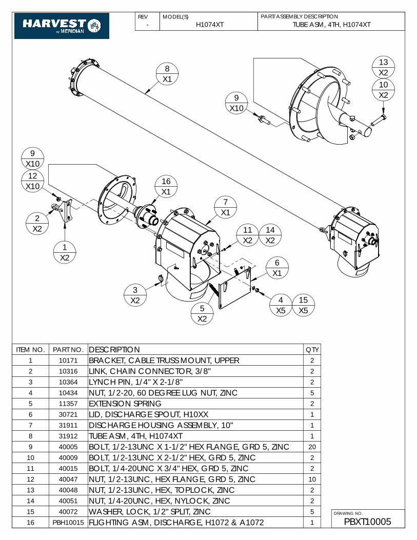
PBXT10005
H1074XTPART/ASSEMBLY DESCRIPTIONREV MODEL(S)
DRAWING NO.
TUBE ASM, 4TH, H1074XT-
ITEM NO. PART NO. DESCRIPTION QTY1 10171 BRACKET, CABLE TRUSS MOUNT, UPPER 22 10316 LINK, CHAIN CONNECTOR, 3/8" 23 10364 LYNCH PIN, 1/4" X 2-1/8" 24 10434 NUT, 1/2-20, 60 DEGREE LUG NUT, ZINC 55 11357 EXTENSION SPRING 26 30721 LID, DISCHARGE SPOUT, H10XX 17 31911 DISCHARGE HOUSING ASSEMBLY, 10" 18 31912 TUBE ASM, 4TH, H1074XT 19 40005 BOLT, 1/2-13UNC X 1-1/2" HEX FLANGE, GRD 5, ZINC 20
10 40009 BOLT, 1/2-13UNC X 2-1/2" HEX, GRD 5, ZINC 211 40015 BOLT, 1/4-20UNC X 3/4" HEX, GRD 5, ZINC 212 40047 NUT, 1/2-13UNC, HEX FLANGE, GRD 5, ZINC 1013 40048 NUT, 1/2-13UNC, HEX, TOPLOCK, ZINC 214 40051 NUT, 1/4-20UNC, HEX, NYLOCK, ZINC 215 40072 WASHER, LOCK, 1/2" SPLIT, ZINC 516 PBH10015 FLIGHTING ASM, DISCHARGE, H1072 & A1072 1
X2
X22
X21
X10
9
12X10
X116
X17
X21411X2
X54
6X1
X25
315X5
8X1
9X10
X210
13X2

CARRIAGE ASM, H10XT
PBXT10009
H1064XT, H1074XT, H1084XTPART/ASSEMBLY DESCRIPTIONREV MODEL(S)
DRAWING NO.
-
NOTES:1) USE P/N 30072 FOR H1064XT & H1074XT
B
X218
C11X2
X1
A
13
15X1
X117X1
12
21X1
D
26
31X4
X210
DETAIL A
8X10
20X2
X82328
X8
16X2
X2 X29 6
X4
22X2
X1
X4X425
DETAIL B
24X4
30
2
29X4
X6
X2X631
DETAIL C
27
26
31X2

X2
DETAIL EX25
X27X2
32X11
27 31X2
E
CARRIAGE ASM, H10XT
PBXT10009
H1064XT, H1074XT, H1084XTPART/ASSEMBLY DESCRIPTIONREV MODEL(S)
DRAWING NO.
-
26
X1
DETAIL DP/N 30082 NOT SHOWN FOR CLARITY
X8
7X119
X13
X4
X14
14
31X8
PBXT10009
H1064XT, H1074XT, H1084XTPART/ASSEMBLY DESCRIPTIONREV MODEL(S)
DRAWING NO.
CARRIAGE ASM, H10XT-
ITEM NO. PART NO. DESCRIPTION QTY1 10149 SHAFT, MID HINGE, 1" X 17" LONG 12 10197 PLATE, CROSS MOUNT CARRIAGE STABILIZER 13 10198 PIN, UPPER CYLINDER, H10, 1-1/2 X 7-1/2" 14 10199 PIN, LOWER HYDRAULIC CYLINDER 15 10245 ZERK, GREASE, 1/4-28UNF, STRAIGHT 26 10308 PIN, COTTER, 3/16x1.5" 27 10383 PIN, ROLL, 3/8" X 2" ZINC 68 10434 NUT, 1/2-20, 60 DEGREE LUG NUT, ZINC 109 10714 PIN, CLEVIS, 1" X 4-1/2" 2
10 13167 HITCH PIN, 3/4 X 4" UL 211 30076 CARRIAGE ARM ASM, LOWER, H10XX 212 30078 SCISSOR ARM ASM, LOWER CARRIAGE LIFT, RIGHT SIDE 113 30079 SCISSOR ARM ASM, LOWER CARRIAGE LIFT, RIGHT SIDE 114 30081 CROSS TUBE ASSEMBLY,LOWER CYLINDER LIFT,10XX 115 30082 ARM ASSEMBLY, UPPER CARRIAGE LIFT, H1082 116 30084 SPINDLE, ASSEMBLY, 10" AUGERS 217 30085 TRANSPORT SUPPORT TUBE ASSEMBLY H10XX 118 30089 TRUSS ROD ASSEMBLY, LOWER CARRIAGE 219 30093 CYLINDER, 4" X 36" 120 30103 205/75 x 15" BIAS PLY TIRE & 5 BOLT RIM ASM 221 31913 AXLE ASM, H10XT 122 31914 AXLE EXTENSION ASM, H10XT 223 40005 BOLT, 1/2-13UNC X 1-1/2" HEX FLANGE, GRD 5, ZINC 824 40017 BOLT, 1-8UNC X 2" HEX, GRD 8, ZINC 425 40025 BOLT, 3/8-16UNC X 1" HEX FLANGE, GRD 5, ZINC 426 40041 BOLT, 5/8-11UNC X 1-1/2" HEX FLANGE, GRD 5, ZINC 2027 40042 BOLT, 5/8-11UNC X 2" HEX FLANGE, GRD 5, ZINC 428 40047 NUT, 1/2-13UNC, HEX FLANGE, GRD 5, ZINC 829 40052 NUT, 1-8UNC, HEX, TOPLOCK, ZINC 430 40056 NUT, 3/8-16UNC, HEX FLANGE, GRD 5, ZINC 431 40061 NUT, 5/8-11UNC, HEX FLANGE, GRD 5, ZINC 2432 40065 WASHER, FLAT, 1", ZINC 2

INFEED HOUSING ASM, H10XT
PBXT10010
H1064XT, H1074XT, & H1084XTPART/ASSEMBLY DESCRIPTIONREV MODEL(S)
DRAWING NO.
-
37X4
X2
39X4
16X1
38X8
14X4
45X1
X437
45X4 1
X1
X123
37X1
44X1
X113
51X1
19X1
18X1
26X1
54X1
39X8
30X2
45X4
36 X4
X4
X234
43
44X2
27X1
7X1X1
X146
40
X1
X2
55
X4
X8
45
50
39
45X8
2X1
15
45X4
X125
X16
12
X2
X1
X1X1910 17
X1
X1 X148
X347 3341
X1
X15
X44942X4
X124
X54537X5
X232 42X2
4
29X1

PART/ASSEMBLY DESCRIPTIONREV MODEL(S)
DRAWING NO.
INFEED HOUSING ASM, H10XT
PBXT10010
H1064XT, H1074XT, & H1084XT-
37X4
31X1
8X1
28X1
B
X1
DETAIL B
X335
X33
X122
X121
X153
X152
20
43X3
PART/ASSEMBLY DESCRIPTIONREV MODEL(S)
DRAWING NO.
PBXT10010
-
ITEM NO. PART NO. DESCRIPTION QTY1 10100A BRACKET, PTO SUPPORT, H10XX 12 10131B BRACKET, WINCH MOUNT, BOLT ON 13 10151 1/2" CLAMP, GALV,VINYL,HYDRAULIC HOSE RETAIN 34 10248 SPROCKET, #60, 20 TOOTH, 1-1/4" BORE 15 10300 SPROCKET, IDLER, #60, 11 TOOTH, 1/2" BORE 16 10307 KEY, 1/4 X 1" 27 10309 KEY, 1/4" X 1-1/2" 18 10324 1/2 NPT MALE TIP, 1/2" BODYSIZE (8010-4) (PIONEER) 19 10553 CONNECTOR LINK, #60 ROLLER CHAIN 1
10 10824 LINK, HALF, #60 OFFSET 111 10955 SET SCREW, 5/16-18UNC X 1/2" 112 11052 SPROCKET, #60 X 18 TOOTH, 1-1/4" BORE 113 11210 BRACKET, CLEVIS POSITION, RETAIN, 10" 114 13104 PLATE, HOLD DOWN, SWIVEL, H10XT 415 13105 COVER PLATE, SIDE, INFEED, H10XT 216 13106 COVER PLATE, TOP, INFEED, H10XT 117 13153 CHAIN, ROLLER, #60 X 44 ROLLERS, INFEED, H10XT 118 30006A CLEVIS HITCH ASSEMBLY, FORMED, A1072 & H10XX 119 30087 PTO SHAFT ASM, COMPLETE, 10" 120 30094 HOSE ASM, 3/8" X 50FT, H13XX 121 30095 VALVE, BALL, 1/4" NPT 122 30098 HYD HOSE ASM, 1/4"x72",#6JIC FEMALE - 1/2" NPTF 123 30109 CHAIN, PTO SHAFT SUPPORT 124 30552 BEARING, 1-1/4", 4 BOLT CAST, LOCK COLLAR 125 30553 1.25" 2 BOLT CAST FLANGE WITH BEARING 126 30749 JACK. 5000LB SIDE WIND 127 31894 INFEED HOUSING ASM, H10XT 128 31895 HITCH ASM, INFEED, H10XT 129 31896 FLIGHTING ACCESS ASM, INFEED, H10XT 130 31897 CLEAN OUT DOOR ASM, INFEED, HXT 231 32010 GEARBOX LOWER H10XX 132 40005 BOLT, 1/2-13UNC X 1-1/2" HEX FLANGE, GRD 5, ZINC 233 40007 BOLT, 1/2-13UNC X 2" CARRIAGE, GRD 5, ZINC 134 40012 BOLT, 1/4-20UNC X 1" HEX, GRD 5, ZINC 435 40015 BOLT, 1/4-20UNC X 3/4" HEX, GRD 5, ZINC 336 40021 BOLT, 3/4-10UNC X 4-1/2" HEX, GRD 5, ZINC 237 40025 BOLT, 3/8-16UNC X 1" HEX FLANGE, GRD 5, ZINC 1838 40027 BOLT, 3/8-16UNC X 1-1/4" HEX FLANGE, GRD 5, ZINC 839 40030 BOLT, 3/8-16UNC X 3/4" HEX FLANGE, GRD 5, ZINC 1640 40036 BOLT, 5/16-18UNC X 3" HEX, GRD 5, ZINC 141 40046 NUT, 1/2-13UNC, GRD 5, ZINC 142 40047 NUT, 1/2-13UNC, HEX FLANGE, GRD 5, ZINC 643 40051 NUT, 1/4-20UNC, HEX, NYLOCK, ZINC 744 40055 NUT, 3/4-10UNC, HEX, TOPLOCK, ZINC 345 40056 NUT, 3/8-16UNC, HEX FLANGE, GRD 5, ZINC 2846 40060 NUT, 5/16-18UNC, HEX, TOPLOCK, ZINC 147 40066 WASHER, FLAT, 1/2", ZINC 348 40072 WASHER, LOCK, 1/2" SPLIT, ZINC 149 40102 BOLT, 1/2-13UNC X 1-1/2" CARRIAGE, GRD 5, ZINC 450 40158 WASHER, FLAT, 3/8", ZINC 851 40212 BOLT, 3/4-10 UNC, X 5" HEX, GRD 5, ZINC 152 6400-06-04 FITTING, #6JIC MALE TO #4 O-RING MALE 153 6400-06-04-0625 FITTING, #6JIC MALE TO #4 O-RING MALE, ORIFACE 154 PB10001 WINCH & MOUNT BRACKET ASSEMBLY 155 PB10004 CHAIN COVER ASM, INFEED, H10XT 1
NOTES:1) PARTS NOT SHOWN:
13145 - HOSE CLAMP; QTY 2PBXT10011
H1064XT, H1074XT, & H1084XTPART/ASSEMBLY DESCRIPTIONREV MODEL(S)
DRAWING NO.
SWING TUBE ASM, H10XT-
A
13X1
B
24X8
36
X1
DETAIL BX4
X1228 33
X1211X2
10X1
31X2
14X1
16X1
X330
35X3
1X1
17
X837
24X2
23 37X2
X23
DETAIL A
5X2
26X2
19X1
29X6
X1234 29
X12
20X2
X167
X1
8X2 X4
27 32X4
22X1
18X1
9X1
X1X1435
X225
31X2
12X1
X1
X2
2
X2X2
33
36
21X1
PART/ASSEMBLY DESCRIPTIONREV MODEL(S)
DRAWING NO.
PBXT10011
-
ITEM NO. PART NO. DESCRIPTION QTY1 10056 DOOR, CLEAN OUT, SWING HOPPER, 10" 12 10309 KEY, 1/4" X 1-1/2" 13 10364 LYNCH PIN, 1/4" X 2-1/8" 24 10382 SET SCREW, 5/16-18UNC X 1-1/4" 15 11761 PLATE, SWING TUBE RETAIN, 10” AUGERS 26 12513 CHAIN, DOUBLE 50 X (18 ROLLERS) 17 12514 LINK, CONNECTOR, DOUBLE 50 18 13033 BRACKET, LATCH, SWING TUBE DISCHARGE HEAD, 10" 29 13144 HOSE, SEAL, SWING TUBE, H10XT 1
10 13160 HINGE, RUBBER, SWING TUBE, H10XT 111 13161 STRAP, RUBBER HINGE, SWING TUBE, H10XT 212 30007 GEARBOX, SWING HOPPER DRIVE, UPPER, H10XX 113 30009A SWING TUBE ASSEMBLY, 10" 114 30011 HINGE ASM, SWING HOPPER, 10" 115 30092 14N U-JOINT 1 1/4 X 14 SP 116 30550 1" 3 BOLT FLANGE WITH FAFNIR BEARING 117 30718 HANGER BEARING ASM, FORMED, 10" 118 31899 SWIVEL RING ASM, H10XT 119 31901 SWING TUBE HEAD ASM, H10XT 120 31902 HUB & SPROCKET ASM, SWING TUBE, H10XT 221 31904 FLIGHTING ASM, SWING TUBE, H10XT 122 31915 LID ASM, SWING TUBE HEAD, H10XT 123 40003 BOLT, 1/2-13UNC X 1-1/2 SN CARRIAGE, GR5, ZINC 224 40004 BOLT, 1/2-13UNC X 1-1/2" HEX, GRD 5, ZINC 1025 40009 BOLT, 1/2-13UNC X 2-1/2" HEX, GRD 5, ZINC 226 40012 BOLT, 1/4-20UNC X 1" HEX, GRD 5, ZINC 227 40013 BOLT, 1/4-20UNC X 1/2" HEX FLANGE, GRD 5, ZINC 428 40015 BOLT, 1/4-20UNC X 3/4" HEX, GRD 5, ZINC 1229 40025 BOLT, 3/8-16UNC X 1" HEX FLANGE, GRD 5, ZINC 1830 40037 BOLT, 5/16-18UNC X 3/4" CARRIAGE, GRD 5, ZINC 331 40048 NUT, 1/2-13UNC, HEX, TOPLOCK, ZINC 432 40049 NUT, 1/4-20UNC, HEX FLANGE, GRD 5, ZINC 433 40051 NUT, 1/4-20UNC, HEX, NYLOCK, ZINC 1434 40056 NUT, 3/8-16UNC, HEX FLANGE, GRD 5, ZINC 1235 40059 NUT, 5/16-18UNC, HEX FLANGE, GRD 5, ZINC 436 40066 WASHER, FLAT, 1/2", ZINC 637 40126 NUT, 1/2-13UNC, HEX, NYLOCK, ZINC 10

49
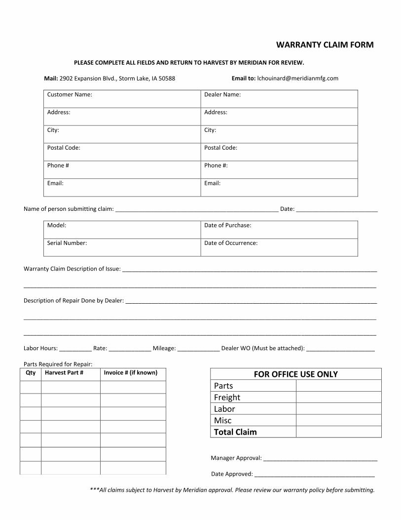
WARRANTY CLAIM FORM
PLEASE COMPLETE ALL FIELDS AND RETURN TO HARVEST BY MERIDIAN FOR REVIEW.
Mail: 2902 Expansion Blvd., Storm Lake, IA 50588 Email to: [email protected]
Customer Name: Dealer Name:
Address: Address:
City: City:
Postal Code: Postal Code:
Phone # Phone #:
Email: Email:
Name of person submitting claim: __________________________________________________ Date: _________________________
Model: Date of Purchase:
Serial Number: Date of Occurrence:
Warranty Claim Description of Issue: ______________________________________________________________________________
____________________________________________________________________________________________________________
Description of Repair Done by Dealer: _____________________________________________________________________________
____________________________________________________________________________________________________________
____________________________________________________________________________________________________________
Labor Hours: __________ Rate: _____________ Mileage: _____________ Dealer WO (Must be attached): _____________________
Parts Required for Repair:
FOR OFFICE USE ONLY Parts
Freight
Labor Misc
Total Claim
Manager Approval: ___________________________________
Date Approved: _____________________________________
***All claims subject to Harvest by Meridian approval. Please review our warranty policy before submitting.
Qty Harvest Part # Invoice # (if known)

2902 Expansion Blvd.Storm Lake, Iowa 50588PHONE: 712-213-5100
TOLL FREE: 1-800-667-5904EMAIL: [email protected]: www.harvestauger.com
51
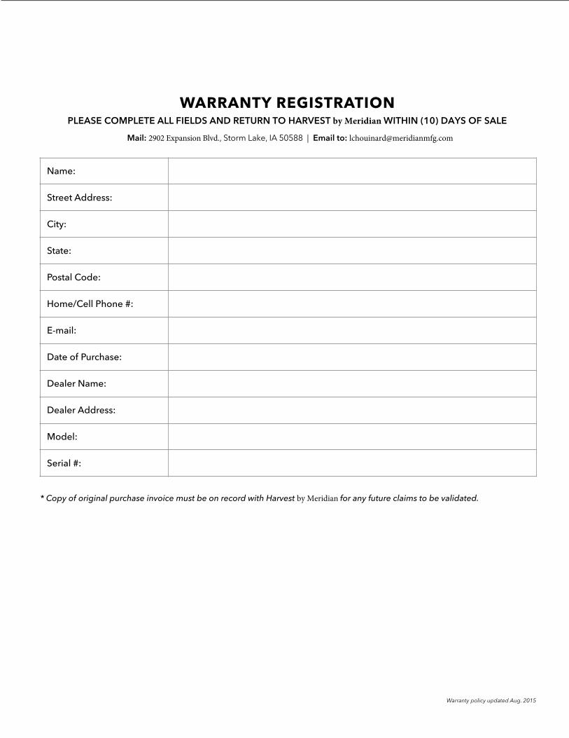
WARRANTY REGISTRATION PLEASE COMPLETE ALL FIELDS AND RETURN TO HARVEST by Meridian WITHIN (10) DAYS OF SALE
Mail: 2902 Expansion Blvd., Storm Lake, IA 50588 | Email to: [email protected]
* Copy of original purchase invoice must be on record with Harvest by Meridian for any future claims to be validated.
Warranty policy updated Aug. 2015
Name:
Street Address:
City:
State:
Postal Code:
Home/Cell Phone #:
E-mail:
Date of Purchase:
Dealer Name:
Dealer Address:
Model:
Serial #: