Embed Size (px)
Citation preview

135
PUMPED STORAGE HYDROPOWER PLANT AVČE – CONSTRUCTION OF UPPER STORAGE RESERVOIRES WITH TWO DAMS AND TECHNICAL
MONITORING
Julijan Bratun, B.Sc.Geol.1, MSc. Alida Rejec, B.Sc.C.2, Miran Komel, B.Sc.C.3, Matjaž Meža, B.Sc.Min.1
1ECONO d.o.o., Ljubljana, 2SENG d.o.o., 3HSE INVEST, Nova Gorica
ABSTRACT
Soške elektrarne Nova Gorica d.o.o. (SENG d.o.o.) the member of Holding of Slovenian Power Plants (Holding Slovenske elektrane d.o.o. Ljubljana) invests in construction of the first pumped storage hydropower plant in Slovenia. The location of pumped storage hydro power plant Avče (Avče PSP) is in western part of Slovenia. The powerhouse is situated on the left bank of the river Soča, downstream from the village of Avče. Positive effects are morphologic, hydrologic and geologic circumstances of location against simultaneous advantages of already existent infrastructure in environment, because the existing reservoir of the Plave hydropower plant, Ajba, shall serve as the lower storage reservoir for Avče PSP and the upper storage reservoir is situated in a natural depression in the vicinity of the Kanalski vrh settlement.
The Upper water-storage reservoir of PSHPP Avče with the volume of 2.200.000 m3, built in the natural basin near the village of Kanalski Vrh, spreads over the area of approximately 15 hectars. For the construction of the earth coffer dams of the upper water storage reservoir the Continuos Compacting Control technology for the dam layers and the AccuGrade GPS metod for the land levelling measurements were used in Slovenia for the first time.
The production launch of Avče PSP was in year 2010. The oscillations of the water in the reservoir present a potential danger for dam collapsing or sliding. Because of stability issues we conducted technical monitoring for two dams of reservoir and drainage gallery. Monitoring is composed from piezometers, inclinometer and geodetic measurement, visual supervision of the slopes and the drainage gallery. Periods of monitoring are different. Piezometers are monitored constantly, geodetic and inclinometer measurements are conducted on every 3 months and visual supervision is conducted once a year.
This article will present the construction of upper storage reservoir with two dams and installed technical monitoring.
Keywords: Pumped storage hydropower plant Avče, construction and technical monitoring, upper storage reservoir.

Pumped Storage Hydropower Plant Avče – Construction Of Upper Storage Reservoires With Two Dams
And Technical Monitoring
136
1. Generalities
During periods when the prices of electricity are low (nights and weekends), the pumped storage hydropower plant Avče is pumping water into the upper storage reservoir. Than it generate electricity during periods when electricity prices are height (peak demand). The pumped storage hydro power plant Avče powerhouse is situated on the left bank of the river Soča, downstream from the village of Avče. The powerhouse features the core power generation hardware.
The existing reservoir of the Plave hydropower plant, Ajba is serving as the lower storage reservoir for pumped storage hydro power plant Avče. The upper storage reservoir is situated in a natural depression in the vicinity of the Kanalski vrh settlement. The headrace tunnel and the penstock connect the upper storage reservoir to the powerhouse.
Embankments are constructed in order to further increase the capacity of the natural basin. The entire reservoir is rendered watertight by means of insulating asphalt lining.
The noteworthy feature of pumped storage hydro power plant Avče is its »varspeed« reversible generator (turbine-pump). That type of generator enables adjustable operation of the pumped storage power plant even in case of fluctuating available power from the power supply network.
Basic characteristics
Installed capacity in turbine operation 185 MW
Installed capacity in pump operation 180 MW
Annual average energy prod. approx 426 GWh
Annual average energy consumption, approx. 553 GWh
Power plant utilization rate 0.77
The other objects of pumped storage hydropower plant Avče who are tipical civil work and we did not describe in the paper are:
Upper storage reservoir
Maximum headwater level 625 m a.s.l.
Minimum headwater level 597m a.s.l.
Effective storage capacity 2.17 million m3
Lower storage reservoir (Ajba)
Maximum tail water level, continuous operation 106.0 m a.s.l.
Minimum tail Water level, continuous operation 104.5 m a.s.l.
Useful daily reservoir volume 0.42 million m3
Penstock
Inner diameter 3.1-3.3 m
Total length 862 m

J. Bratun, A. Rejec, M. Komel, M. Meža
137
Picture 1 Location of the pumped storage hydropower plant Avče
2. Technology of construction of two embankment dams of accumulation
The term »CCC – Continuous Compaction Control« defines contemporary procedures that enable continuous monitoring of soil responses to vibrations transferred by dynamic rollers into the soil during their functioning. The measuring system, integrated into the roller, enables continuous control over the events in the soil and continuous monitoring of the roller actions. The values obtained in the measurements with the CCC procedures are dynamic measuring values. The achieved compaction quality is deduced indirectly, through a preliminary calibration system, performed by using conventional methods, especially the static and dynamic circular plates. Primorje Ajdovščina used the Roller integrated continuous compaction control in 2007 during the construction of two embankment dams for the accumulation pool at the Pumping Power Station Avče (Slovenia). This was for the first time that the CCC system was used for quality control as well as acceptance criteria in Slovenia. The paper presents the procedures of continuous compaction control, documented with
Pumped Storage Hydropower Plant Avče – Construction Of Upper Storage Reservoires With Two Dams
And Technical Monitoring
138
results from the job site Avče and some other motorway job sites. The purpose of the paper is to present the advantages of CCC systems and to bring the CCC procedures closer to all those who are directly or indirectly included into the process of the construction of embankments and other types of unbound layers.
2.1 Presentation of the location
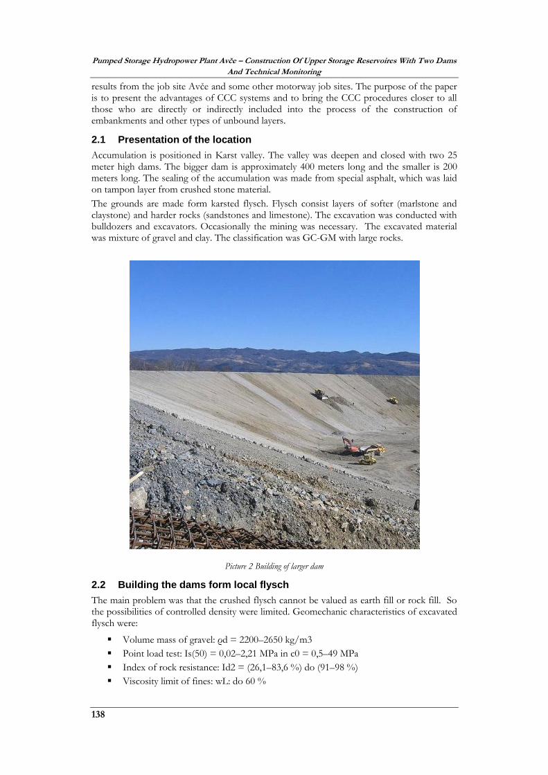
Accumulation is positioned in Karst valley. The valley was deepen and closed with two 25 meter high dams. The bigger dam is approximately 400 meters long and the smaller is 200 meters long. The sealing of the accumulation was made from special asphalt, which was laid on tampon layer from crushed stone material.
The grounds are made form karsted flysch. Flysch consist layers of softer (marlstone and claystone) and harder rocks (sandstones and limestone). The excavation was conducted with bulldozers and excavators. Occasionally the mining was necessary. The excavated material was mixture of gravel and clay. The classification was GC-GM with large rocks.
Picture 2 Building of larger dam
2.2 Building the dams form local flysch
The main problem was that the crushed flysch cannot be valued as earth fill or rock fill. So the possibilities of controlled density were limited. Geomechanic characteristics of excavated flysch were:
Volume mass of gravel: ρd = 2200–2650 kg/m3
Point load test: Is(50) = 0,02–2,21 MPa in c0 = 0,5–49 MPa
Index of rock resistance: Id2 = (26,1–83,6 %) do (91–98 %)
Viscosity limit of fines: wL: do 60 %

J. Bratun, A. Rejec, M. Komel, M. Meža
139
Index of fines plasticity: IP:, 20–35 % in crushed marlstone
Humidity: w0 = 1,1–7 %
Optimal humidity by Proctor: wopt.: 6–10 %
Maximal dry density by Proctor ρdmax.: 2170–2200 kg/m3
The picture 3 shows the weathering of flysch. First it disintegrates in smaller blocks and gravel. After a while it disintegrates in clay. Time of disintegration is form few days to few months.
Based on experience, we know that high dams and embankments collapse from 1 to 3 % of its own height. They collapse because of uneven compaction during construction, consolidation of lower layer due to extra weight and arrangement of pebbles in stable orientation [Petkovšek, Majes 2001].
Picture 3 Weathering of the flysch
Results of density measurement with isotopic probe or deformation modules with the dinamic plate do not show the real situation, since their depth range is too small. Friction between the grains in freshly compacted layers is high enough to give a false impression of high strength and stiffness. The shortcomings of classical methods of measuring the density and stiffness can be replaced with the use of rollers with CCC system and controling of suction. Based on experience we know that collapsing of embankments, compacted with CCC is 10 to 30 time lower than compacting with classical roller.
After thorough research and analysis, it was concluded that the flysch can be installed in the partition dams under the following conditions.
For compaction and compaction control were used rollers with built CCC,
The dams are built wetted materials with 85% saturation, which still provides low
suction,
Criteria for evaluating the quality and acceptance embankments layers is a dynamic
measurement value. Between the penultimate and final crossing the difference in
growth of DMV must be less than 5%.
The collapsing of embankments was evaluated between 2,4 to 7,4 cm. With use of classic rollers the collapse it is evaluated to 58 cm. Vertical and horizontal movement of dams during the construction, were monitored with geotechnical monitoring.
2.3 Construction and quality control with CCC system
For the construction and monitoring of compaction was use the 16-ton vibratory roller BOMAG BW 216 D-4, with a working width of the 213 cm. It is possible to use two frequencies, ƒ1 = 31 Hz and ƒ2 = 36 Hz and two amplitudes 1.80 and 0.85 mm. Depth of impact compaction is up to 0.8 m, the depth of measurement is 1.2-1.5 m. Roller is equipped with a measuring system Terameter, endowed with an overall data processing Bomag Compaction Management BCM 05.

Pumped Storage Hydropower Plant Avče – Construction Of Upper Storage Reservoires With Two Dams
And Technical Monitoring
140
In April-May 2007 four experimental fields for calibration were carried out. Most problems for calibration produced. Large grain size above 100 mm, lenses of clay and unevenness on the surface represented the most problems during the calibration. Comparative measurements were performed with circular plate with light falling weight. Value Evd = 50 MPa corresponding to a dynamic measured value Evib = 157.7 MPa. The value Evib = 175 MPa was achieved with no problems. The most important criteria for dams are density. With the use of CCC both dams were built in the period from June to September 2007. Due to tight deadlines, we built the dams with rollers without embedded systems CCC. Control measurements were conducted with roller with CCC. For building both dams there were used 441,000 m3 of material. All material was obtained with the excavation at the site. In order to evaluate data, we used the upgraded system BCM 05.
Analysis of the all measurements during the construction showed that the average value of the measurement on a large dam was Evib = 187 MPa, and on the smaller dam Evib = 176 MPa. All the measured values were within the demanded values.
Picture 4 Bigger north dam
J. Bratun, A. Rejec, M. Komel, M. Meža
141
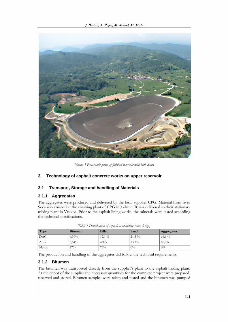
Picture 5 Panoramic photo of finished reservoir with both dams
3. Technology of asphalt concrete works on upper reservoir
3.1 Transport, Storage and handling of Materials
3.1.1 Aggregates
The aggregates were produced and delivered by the local supplier CPG. Material from river Soča was crushed at the crushing plant of CPG in Tolmin. It was delivered to their stationary mixing plant in Vrtojba. Prior to the asphalt lining works, the minerals were tested according the technical specifications.
Table 1 Distribution of asphalt composition (mix design)
Type Bitumen Filler Sand Aggregates
DAC 6,30% 12,1 % 21,3 % 66,6 %
ALB 3,54% 4,9% 13,1% 82,0%
Mastic 27% 73% 0% 0%
The production and handling of the aggregates did follow the technical requirements.
3.1.2 Bitumen
The bitumen was transported directly from the supplier’s plant to the asphalt mixing plant. At the depot of the supplier the necessary quantities for the complete project were prepared, reserved and stored. Bitumen samples were taken and tested and the bitumen was pumped

Pumped Storage Hydropower Plant Avče – Construction Of Upper Storage Reservoires With Two Dams
And Technical Monitoring
142
directly into the bitumen tanks. After issuing the satisfying results, the bitumen was used for the asphalt production.
3.1.3 Filler
The filler was stored in silos close to the asphalt mixing plant. The limestone filler was produced and supplied by CPG in Tolmin and Laže. The material was tested prior to the elaboration of the mix design. A permanent quality control according to the technical specifications was arranged. The filler in the silos was kept dry at constant conditions.
3.2 Production of bituminous material
3.2.1 Bituminous concrete
The aggregates were produced and stored separately. The local stationary asphalt mixing plant of CPG in Vrtojba was chosen for the production of the asphalt. The plant was reserved for the asphalt production at the upper reservoir only.
The asphalt mixing plant had a peak capacity of 85 tons for dense asphalt per hour, batching approx. 1,5 tons by discontinuous production. The mixed asphalt was loaded directly onto a 4 axle tripper. The procedure including all relevant data was controlled and adjusted bj the computerized terminal. Every load finally passed over a weigh-bridge being transported to the reservoir.
3.2.2 Hot mastic sealing
The mastic material was supplied by the Primorje asphalt mixing plant in Laže and directly loaded into mobile mastic cookers. The cookers are equipped with an in depended and controlled heating system and the necessary mixer. In the cooker the material was heated and stirred to achieve the homogeneity of the filler bitumen mix. The finished material was transported to the mastic paver.
3.3 Placing of the bituminous concrete
3.3.1 Asphalt placing of slope
The asphalt was produced in the asphalt plant as described above and transported by suitable tippers to the slope and the first roller. The winch supports the paver, the feeding wagon in the slope and the first roller. The winch in movable on tracks and in placed at the crest. The tipper dumped the asphalt into an isolated contained. There it was loaded by a long reach excavator to the feeding wagon, which transported and tipped the asphalt to the paver.
The paver operates on tracks in the slope and places the asphalt in vertical strips from dam toe including the radius up to the crest. The paver is equipped with the high compaction screed of variable up to 5 m. at the open side of the paver a forming and compaction shoe ensured a compaction of the complete strip.

J. Bratun, A. Rejec, M. Komel, M. Meža
143
Picture 6 Asphalt laying
The capacity of the feeding unit did allow a permanent and high performance placing. The paver and the wagon are pulled into the main winch itself. By this system a mechanised placing was done to the very top of the crest. The main winch including the mounted paver and wagon then moved sideward and the placing continued at the adjacent strip.
The first roller was supported by the main winch. It did compact the asphalt layer immediately. A second roller followed, which is supported and secure by mobile roller winches. The rollers were pulled up onto ramps at the winches and did compact the asphalt layers up to the crest. The compaction did continue until the required compaction ratio was achieved.
The screed followed the existing cushion layer and installed the bituminous layers according the requirements. The thickness was controlled and adjusted permanently. In areas with a modulated sub-surface the paver reduced such modulations. Locally increased thickness in not a harm to the sealing system and needs no further treatment.
The placing has been adapted according site requirements. The slope placing group did work wherever a sufficient area was prepared. When the weather conditions were favourable, the dense layer was installed to cover and protect the previously installed binder layer.
3.3.2 Asphalt placing in the base
The asphalt material was transported by 4 axle trucks form the plant to the paver and directly tipped into the hopper of the paver. The paver placed and compacted the material as described above. The final compaction was done with independent rollers.
To avoid dirt or dust interfering with the asphalt works, the binder layers was sealed as soon as possible with the impervious layer. When necessary the binder layer has been cleaned and pre-treated with a slight coat film. The placing started preferably at the corners and then moved towards the ramp area. Therefore traffic on already installed areas was reduced. To

Pumped Storage Hydropower Plant Avče – Construction Of Upper Storage Reservoires With Two Dams
And Technical Monitoring
144
enable the joint construction to the intake/outlet structure, those areas have been started as soon as possible.
3.3.3 Treatment of joints
The open side of each placed strip was formed by the shoe at the screed of the paver. The end of each strip was levelled, formed to a straight line and compacted by the rollers. To ensure the required void content for dense layer, an adhesive glue coating was applied to the surface of a cold joint – prior to the placing at the next day.
After the placing and cooling down of the dense layer, the cold joints were treated. An infrared heating unit heated up the joint area. The reheated asphalt was re-compacted by manually operated vibro tampers. The experience of the last decades has proven, that only by this method a homogenous and impervious sealing system can be achieved.
This works were done carefully and with great experience to guarantee the impermeability and void content in every part of the sealing system. The same method was used in areas, where samples had been taken.
Trafic and other loads by third parties had not been permitted and the completed and sealed areas had been kept free from any unnecessary stress.
3.3.4 Hot mastic sealing
After the installation of the impermeable layer and treatment of the joints the mastic sealing was applied.
The mastic material was supplied by the Primorje asphalt mixing plant in Laže and directly loaded into mobile mastic cookers. The cookers are equipped with an independent and controlled heating system and the necessary mixer. In the cooker the material was heated and stirred to achievable the homogeneity of the filler bitumen mix. Then the material was transported to the mastic paver.
The installation of the filler mastic at a ratio of 2 kg/m2 was done at one pass and dried up immediately after placing. The placing was done by mastic paver at high performance.
The homogenous mastic material was poured into the mastic paver. For mastic placing in the slope, the plave was pulled by winch form the dam toe to the crest. The mounted paver then moved sideward by moving the winch. An overlapping of the strips is standard. In the bottom area the mastic paver was pulled by a roller or a loader.
According to the experience of realised projects the mastic mixture shall a Ring-and-Ball value of >75°C. The mastic sealing showed after a certain time some “mastic tears” creeping traces and “elephant skin”. These effects are only of optical nature and will have no influence to the purpose of the mastic coating. In corners and close to structures mastic was placed manually by use of sweepers.
3.3.5 Road work at ramp and other areas
The wearing course at the ramp and in other areas was placed by paver and followed the method as stated above. Due to the fact, that asphalt lining works in the ramp area stopped the access to the reservoir, the timing of this work was arranged with the other involved parties.
3.4 Construction schedule
The construction works were realised from 12 of May 2008 until 19 of September 2008. Based on given information in the bid, following program is intended.
Site installation including offices, laboratory and workshop was done previously to the construction in May 2008.

J. Bratun, A. Rejec, M. Komel, M. Meža
145
The material investigation and the elaboration of the mix designs started at the end of March 2008. Prior to trails at the mixing plant in May 2008, the suitability tests / mix design was completed at the end of April. The placing test and industrial were done in May 2008.
The installation of the asphalt in the base and in the slope was done simultaneously, but slope was favoured. The treatment of the joints was done continuously. The installation of the mastic sealing was realised without heavy equipment and was done in two stages.
Due to the good performance of the asphalt mixing plant and the use of specialised placing groups the installation of up to 1000 tons/day was feasible.
Picture 7 Construction schedule
4. Technical monitoring for two dams of reservoir and drainage gallery
4.1 Geodetic measurements
Within the monitoring of the geodetic measurements of displacements of stabile points were conducted periodically. Locations of level 20 items are tagged with LP shown in lower picture: Upper Pool Avče - show locations of measurements.
Measurements during the first filling were carried out according to the program of technical observation.
Zero measurement was carried out before filling the reservoir. This was followed by controlling measurement at each stage of the gradual filling and control measurements after

Pumped Storage Hydropower Plant Avče – Construction Of Upper Storage Reservoires With Two Dams
And Technical Monitoring
146
discharge and refilling the pool. The first three years of operation provided 4 measurements a year later, after that period, two measurements per year.
4.2 Inclinometers
Inclinometers are measuring horizontal displacements of the dams. Two (I1 and I3) are mounted on the crowns of the two divisions and one (I2) to the southern slope. Measurements are carried out at the same time as the geodetic survey.
4.3 Piezometers
Around the entire reservoir there are 14 piezometers with piezometric tube, inserted into the bore, length of between 9.5 and 25.5 m. The locations of piezometers are tagged with P and are shown in Figure 3. The measurement of the water levels has to be carried out before filling and in all phases of filling of accumulation. The measurements are carried out continuously, by reading results from the sensors and within the agreed terms. When the power plant working, there are 3 readings a day. Within the quick filling or emptying of the pool the reading of water levels is every 2 hours. For each measurement, it is necessary to measure the water level. We also regularly monitor the meteorological data (temperature and precipitation). The measures of the water level in drainage gallery are also conducted.
4.4 Visual examination of dams and drainage gallery
Visual inspection of the dams and the drainage gallery is conducted once a year the. We carefully inspect outer side of the dams. We look for the points of erosion, cracks, drainage system on surface.
In the visual inspection of the drainage gallery we look for cracks, water leaks, measuring the cracks with crack meter.
5. Result of the monitoring
5.1 Geodetic measurements
Measurements have shown that in the period from 2009 to 2012, values of the cumulative deformation are less than 5 mm. These measures present no concern for stability of the reservoir.
5.2 Inclinometers
The conducted measures of inclinometers show no larger deformations in horizontal way.
The cumulative values of the measured displacements are small and do not exceed 4 mm.
Reasons for displacements are natural compacting of the material in dams and influence of changing water level.
5.3 Piezometers
In all observation period there was no significant increase or decrease of water levels. Occasionally, there is an increase in the level of piezometer P14, which is attributed to a back-infiltration of water, which was confirmed by the constant temperature of groundwater.
5.4 Visual examination of dams and drainage gallery
The drainage gallery is general dry. Water occurs only at the curve of the gallery, but there is not visible flow of the water. The central channel of the drainage was dry during the inspection. The walls were slightly damp.

J. Bratun, A. Rejec, M. Komel, M. Meža
147
The flow meter did not register any water; these mean that the reservoir is sealed. During the inspection we found some cracks. We mounted crack meters and take a lot of pictures. Over the years it will show, which cracks are active and which are not.
The outer slopes of the dams are slightly eroded, but this is no reason for concern. We did not find any signs of slides or cracks.
6. Conclusion
As presented in article, works were conducted with quality and the results from the monitoring are confirming the quality. Before the start of the works there were a lot of discussions with designer about material that can be used for construcion of two dams: flisch material from local excavation or limestone material transported from the quarry. Economical and technical analises helped us to select flisch material for the construction of the two dams. Monitoring results show us that both dams are stable and the technology for consolidation of the flysch gravel was the correct decision.
7. References
[1] http://www.dlib.si/stream/URN:NBN:SI:DOC-DWQBQ1RC/d0b8ec0a-aa68-4a5b-b05c-10917ee60e84/PDF [Accessed 16 July.2013]
[2] http://www.seng.si/galerija/che_avce/2008100807490778/[Accessed 16 July.2013]
[3] Primorje d.d., 2007: Zaključno poročilo o kontinuiranih površinskih dinamičnih meritvah zgoščenosti, Ajdovščina
[4] SENG: Boršura ČHE Avče
[5] SENG: Perspektiva energije – Črpalna hidroelektrarna Avče na reki Soči
[6] Walo Bertschinger: PSP Avče – Upper reservoir Lot 2. Asphalt Concrete Works, Construction methode statement