Embed Size (px)
Citation preview


Publisher: LuK GmbH & Co.Industriestrasse 3 • D -77815 Bühl/Baden
Telephon +49 (0) 7223 / 941 - 0 • Fax +49 (0) 7223 / 2 69 50Internet: www.LuK.de
Editorial: Ralf Stopp, Christa Siefert
Layout: Vera WestermannLayout support: Heike Pinther
Print: Konkordia GmbH, BühlDas Medienunternehmen
Printed in Germany
Reprint, also in extracts, withoutauthorisation of the publisher forbidden.

Foreword
Innovations are shaping ourfuture. Experts predict that therewill be more changes in the fieldsof transmission, electronics andsafety of vehicles over the next15 years than there have beenthroughout the past 50 years. Thisdrive for innovation is continuallyproviding manufacturers and sup-pliers with new challenges and isset to significantly alter our worldof mobility.
LuK is embracing these challen-ges. With a wealth of vision andengineering performance, ourengineers are once again provingtheir innovative power.
This volume comprises papersfrom the 7th LuK Symposium andillustrates our view of technicaldevelopments.
We look forward to some intere-sting discussions with you.
Bühl, in April 2002
Helmut Beier
Presidentof the LuK Group

Content
LuK SYMPOSIUM 2002
1 DMFW – Nothing New? . . . . . . . . . . . . . . . . . . . . . . . . . . . . . . . . . . 5
2 Torque Converter Evolution at LuK . . . . . . . . . . . . . . . . . . . . . . . 15
3 Clutch Release Systems . . . . . . . . . . . . . . . . . . . . . . . . . . . . . . . . 27
4 Internal Crankshaft Damper (ICD). . . . . . . . . . . . . . . . . . . . . . . . . 41
5 Latest Results in the CVT Development. . . . . . . . . . . . . . . . . . . . 51
6 Efficiency-Optimised CVT Clamping System . . . . . . . . . . . . . . . 61
7 500 Nm CVT . . . . . . . . . . . . . . . . . . . . . . . . . . . . . . . . . . . . . . . . . . 75
8 The Crank-CVT . . . . . . . . . . . . . . . . . . . . . . . . . . . . . . . . . . . . . . . . 89
9 Demand Based Controllable Pumps. . . . . . . . . . . . . . . . . . . . . . . 99
10 Temperature-controlled Lubricating Oil Pumps Save Fuel . . . 113
11 CO2 Compressors . . . . . . . . . . . . . . . . . . . . . . . . . . . . . . . . . . . . 123
12 Components and Assemblies for Transmission Shift Systems135
13 The XSG Family . . . . . . . . . . . . . . . . . . . . . . . . . . . . . . . . . . . . . . 145
14 New Opportunities for the Clutch?. . . . . . . . . . . . . . . . . . . . . . . 161
15 Electro-Mechanical Actuators. . . . . . . . . . . . . . . . . . . . . . . . . . . 173
16 Think Systems - Software by LuK. . . . . . . . . . . . . . . . . . . . . . . . 185
17 The Parallel Shift Gearbox PSG . . . . . . . . . . . . . . . . . . . . . . . . . 197
18 Small Starter Generator – Big Impact . . . . . . . . . . . . . . . . . . . . . 211
19 Code Generation for Manufacturing. . . . . . . . . . . . . . . . . . . . . . 225

135LuK SYMPOSIUM 2002
Components and Assemblies for Transmission Shift Systems
Reinhart Malik, INA
12
12
12 Components and Assemblies for Transmission Shift Systems
136 LuK SYMPOSIUM 2002
IntroductionAll vehicle transmissions require devices andcontrols that serve to adjust the transmissionto particular driving conditions. This is not de-pendent on the transmission design. It ismerely the design of electrical, hydraulic ormechanical actuation elements that describethe type of shifting. (figure 1).
For manually operated transmissions, shiftelements are required, which in turn place de-mands on stiffness, surface quality, wear be-haviour and other characteristics dependingon the application.
Fig. 1: Application Example: 6 Speed Transver-sally Mounted Manual Transmission
For non-automatic shift systems, there is theadditional requirement that the driver mustperceive shifting as a smooth and perfect pro-cess.
Measures relating to both technology and de-sign allow shift elements to be achieved thatmeet a wide variety of requirements. Cold for-med precision parts and new ideas for assem-bly designs are among the promising develop-ments in this regard.
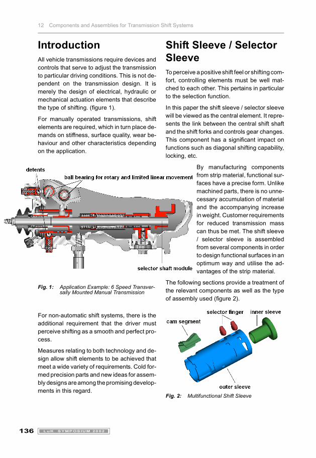
Shift Sleeve / Selector SleeveTo perceive a positive shift feel or shifting com-fort, controlling elements must be well mat-ched to each other. This pertains in particularto the selection function.
In this paper the shift sleeve / selector sleevewill be viewed as the central element. It repre-sents the link between the central shift shaftand the shift forks and controls gear changes.This component has a significant impact onfunctions such as diagonal shifting capability,locking, etc.
By manufacturing componentsfrom strip material, functional sur-faces have a precise form. Unlikemachined parts, there is no unne-cessary accumulation of materialand the accompanying increasein weight. Customer requirementsfor reduced transmission masscan thus be met. The shift sleeve/ selector sleeve is assembledfrom several components in orderto design functional surfaces in anoptimum way and utilise the ad-vantages of the strip material.
The following sections provide a treatment ofthe relevant components as well as the typeof assembly used (figure 2).
Fig. 2: Multifunctional Shift Sleeve

12 Components and Assemblies for Transmission Shift Systems
137LuK SYMPOSIUM 2002
Outer SleeveThis component represents the outer portionof the multifunctional shift sleeve and has animpact on functions due to profiles and sur-faces.
A special process is used to form the sleevein just one machining operation. Thus, the de-viations between the various functional sur-faces depend only on the tooling. The toolingused allows a large number of componentswith close tolerances to be manufactured.
With regard to surface quality, functional sur-faces are suitable for the application, and norework in the form of cutting operations is re-quired. The cold formed ramp contours for thedetent pins, which are used to generate shif-ting force, allow a very smooth surface to beachieved. Machining grooves and similarstructures that have a negative effect on shiftfeel can thus be prevented. (figure 3).
Fig. 3: Surface Comparison for SelectorContour: Cutting versus Forming
Inner SleeveThe outer sleeve is secured on the shift shaftby means of a support referred to in this paperas the 'inner sleeve.' The design of this sleeveis determined by the method used to mountthe part on the shaft and the way it is connec-ted to the outer sleeve.
The length and wall thickness for the hub ofthe inner sleeve's press fit depends on the for-
ce/torque to be transmitted. This type of fa-stening between the inner sleeve and shiftshaft has proven to be very advantageous.
Shift FingerThe form of the shift finger is matched to thestriker jaws and the requirements for diagonalshifting capability. The functional surfacesmust be as smooth as possible so as to enablethe shift finger to gently roll off or slide duringshifting. For diagonal shifting motion, thechamfers and transitions on the shift fingerprofiles are especially important. The smoothgliding of the shift finger over the striker jawsis also required. The cold forming operationperformed on the strip material allows all ofthese characteristics to be achieved in oneoperation.
Mounting ToolPrecision parts are produced using simpleand reliable manufacturing methods. The ac-curacy of the assembly is achieved with themounting tool.
Accumulated tolerances can be reduced, thusenabling tight tolerances to be maintained.
Heat TreatmentHeat treatment allows the permissible stressvalues and component hardness to beincreased. Increased hardness prevents wearon component functional surfaces. Here, spe-cial attention must be given to the shift fingerand the ramp profile for the detent pin.
For actuating forces of F > 2000 N, pressureson the shift finger of up to 6000 N/mm² are pre-sent (figure 4). The only way to prevent ex-cessive wear and to maintain a low clearancebetween the shift finger and the meshing withthe shift fork is to use the proper heat treat-ment methods. Shift motion and the diagonalshifting are hardly changed throughout theentire service life.

12 Components and Assemblies for Transmission Shift Systems
138 LuK SYMPOSIUM 2002
Fig. 4: Pressure on Shift Finger
For the ramp profile, the detent overroll overthe smallest radius is a decisive factor. For thedetent pins currently installed in manual trans-missions, spring forces of 140 N can be used.It is absolutely necessary to perform a detailedadjustment of the ramp radii and the pressuresfound here. If the ramp radius changed as aresult of wear, this would bring about changes
to the shifting force and thus shift feel duringthe service life of the transmission (figure 5).
Summary of AdvantagesThe modular design allows cost-effectiveparts in various designs to be matched witheach other. Component dimensions can be ar-bitrarily selected and do not depend on thenumber of slides in the tooling.
Due to the fact that the sleeve is mounted witha press fit, shift shaft design is easy and fle-xible. The type of fastening does not dependon the mating between the steel and the ma-terial. No mechanical machining is requiredfor either part during assembly. No problemsare encountered for the precise positioning ofseveral components with the assembly toolingused.
In addition, no limitations are placed on the op-tion of furnishing the shaft with anti-corrosionprotection.
Fig. 5: Effects of Various Ramp Profiles on Shifting Characteristics.

12 Components and Assemblies for Transmission Shift Systems
139LuK SYMPOSIUM 2002
Neutral PositionThe positioning of the gearshift lever in the ve-hicle depends on the gearshift lever bracket,the control of the central shift shaft and the po-sitioning of the shift shaft in the transmission.Various systems are used for positioning thecentral shift shaft.
Motion in the ShiftingDirectionFor the positioning of the shift shaft in the di-rection of shifting, one proven method hasbeen to arrange the detent pin in conjunctionwith the selector profile on the central shiftshaft. With the detent pin and the selector pro-file, shifting force is also effected in the direc-tion of shifting. In the interaction of severalother components, it makes a significant con-tribution to the overall force curve (figure 6).
Significant effects can be achieved for as-pects such as engagement force at the end ofthe shifting process and the return force whendisengaging the gear. An arbitrarily selectable,adjustable force curve can be represented.
Motion in the SelectionDirectionIn the past, pressure springs were used to po-sition the shift shaft in the selection direction.
Depending on the spring rate and forces, thisconfiguration requires a large design enve-lope in the axial direction. Assembly becomesa problem since several individual parts arerequired.
One possibility here is to use a detent pin thatcontacts the shift shaft with a v-shaped profile.Here, both components and the assemblyprocess can be greatly simplified.
Fig. 6: Influence of Various Components on the Shifting Process

12 Components and Assemblies for Transmission Shift Systems
140 LuK SYMPOSIUM 2002
Compared to control by means of pressuresprings, the curve can be selected arbitrarily.This advantage is utilised primarily for the new6-speed transmissions. A decrease at the cur-ve end-positions can be achieved. This hasadvantages when shifting from fifth to sixth ge-ar. The shift force is not deflected by a high sel-ector force in the 3 / 4 shift gate. This allows er-roneous down-shifting from sixth gear to thirdgear (instead of fifth gear) to be prevented.
At the end of the selection motion, it is possibleto brake this motion by means of a gentleincrease in force. Depending on the applica-tion, a limitation can be achieved by a radiusformed in the profile.
An interlocking can be provided by using anadditional detent pin.
To reduce costs further, the profiles for shiftingand selecting can be brought together. Thismeans that only one detent pin is required togenerate shift and selection force. Machiningcosts for the transmission housing or gearshiftcover can be reduced. It is also possible to re-duce the number of components, which alsohas a positive effect on costs. In addition, thiscombination means that accumulated toleran-ces are very small.
Fig. 7: Three Dimensional Selector Profile for the Selection and Shifting Processes
A cold formed sheet metal component is agood choice for the manufacture of this 3-Dprofile part, (figure 7). Preparing the profile inthe tooling allows a high degree of repeat ac-curacy. These profile sheets are joined withthe other components as mentioned above. Itis possible to manufacture the part as a pre-
cision casting or a sintered component. Howe-ver, the rework cutting operations required to ob-tain a good surface quality is hard to achieve.
The following sections provide a description ofways to improve the shifting comfort of an exi-sting gearshift unit (figure 1).
The gearshift unit investigated showed de-ficiencies due to excessive friction. The leverreturn motion to neutral 3 / 4 was not suf-ficient. This problem was also noticeable in theshifting direction.
The following serves to provide details for theinvestigation and corrective actions for theselection force curve.
The following components were replaced byparts incorporating INA technology:
1. Plain bearing support for the central shiftshaft was replaced by rolling bearings withlimited longitudinal and rotary motion.
2. Plain bearing support for the selector leverwas replaced by needle roller bearings.
3. The boot was replaced by a protectivesleeve and with an additional seal in thehousing.
4. The locking pawl design was replaced bya drum lock.
5. The spring assembly was replaced by a3-D ramp profile for the generation of shiftand selection forces (figure 8).
Effects
For 1) Hysteresis for the shift and selection for-ce curve is reduced.
For 2) Friction is reduced and in turn the hy-steresis for the selection force curve.
For 3) Friction is reduced and in turn the hyste-resis for the selection and shift force curves.
For 4) The number of components moved isminimised, allowing the number of contact po-sitions between the shift forks and the centralshift shaft to be reduced. The pawl, securedby means of a housing, is eliminated.
Zu 5.) Components are eliminated, and cen-tering in 3 / 4 is improved.

12 Components and Assemblies for Transmission Shift Systems
141LuK SYMPOSIUM 2002
Fig. 8: Comparison of Selection Forces
These improvements allowed hysteresis to bereduced from 30 N to 6 N (see figure 8).
In a subjective evaluation from the customer,this significant reduction was assessed asvery positive for the shift feel.
Simulation Techniques in DevelopmentCustomer requirements such as small designenvelope, maximum savings on weight, lowdevelopment costs and fast developmenttimes can also be achieved for the design ofshift systems by using modern CAE tools inthe design work. At INA, methods and pro-grams can be used that are optimally matchedwith the requirements on shift systems(figure 9).
Topology – Optimising the Design of the Shift-Control HousingThe permissible envelope and boundary con-ditions such as load and force applicationpoints are specified. The calculations yield theminimum requirements for the layout of ma-terials under the loads and torques conside-red. Some results can also viewed as imprac-tical casting. The material-based minimummodel must now be designed and/or adjustedto match aspects relevant for manufacturing.
Fig. 9: SAE Methods Used in TransmissionDesign
Finite Element AnalysisStarting with the 3-D design model, wire fra-me/nodes and loads are defined. Currently,component deformations and stresses obtai-ned from the supporting program are general-ly used as the basis for an optimised design.
VSA 3-D Tolerance AnalysisTolerances for dimensions and geometry willdetermine how much work will be necessaryfor manufacturing and assembly. At the sametime, they guarantee that complex systemsfunction properly. In contrast to nominal tole-rance, the static distribution is considered inVSA-3-D. Another advantage of the simulati-on is the ability to draw conclusions about pro-cess parameters and what causes them. Thestarting point is the ‘nominal’ 3-D CAD assem-bly model with its specified reference points

12 Components and Assemblies for Transmission Shift Systems
142 LuK SYMPOSIUM 2002
for the components. The required contact sur-faces and points must be defined for the va-rious functions.
Thus, the 'nominal' model is converted to a'functional' CAD model.
After this, all dimensional and geometric tole-rances to be analysed must be assigned tofunctional surfaces at the component level.
Fig. 10: VSA-3-D Tolerance Analysis
The computer-aided simulation now allowscurves to be evaluated, for example for dia-gonal shift capability from second to third gear.
Not all questions pertaining to the tolerance ana-lysis for a shift system can be solved with onlyone functional 3-D CAD model (figure 10).
The 3-D tolerance analysis can be used for thefollowing:
� Planning phase: to investigate base dimen-sions and the assembly sequence for as-semblies
� Design phase: to define tolerances and vali-date assembly specifications
� Prototype manufacturing phase: to checkand define measuring facilities
� Manufacturing phase: for the process simu-lation of manufacturing tolerances
Filling Simulation
Filling simulation is a calculation procedureused to simulate the operations involved in theinjection moulding of plastic or light metals.
From the 3-D model, filling calculations allowthe designer to recognise the optimum injec-tion, flow behaviour, potential air inclusions orcritical seams.
Kinematic Analysis
In the case of irregular selection or shift be-haviour for example, the kinematic analysis al-lows the simulation of displacement forces fora detent pin across the ramp profile. This inturn allows suitable measures to be taken andpredictions to be made regarding the beha-viour of new surface profiles.

12 Components and Assemblies for Transmission Shift Systems
143LuK SYMPOSIUM 2002
Dynamic AnalysisDynamic analysis is used to recognise move-ments that occur in the interaction of interde-pendent components or assemblies. One ex-ample here is the non-guided (chaotic) systemas is the case for a detent pin having appro-ximately 60 balls arranged in the shape of aspherical cup (figure 11).
Fig. 11: Dynamic Analysis
Development of Cold Formed Synchronisation Components Cold formed precision products represent agreat improvement over machined synchroni-sation systems, not only in terms of the opti-misation of weight and costs. There are alsocharacteristics resulting from forming techno-logy that allow indirect advantages as well(figure 12).
Fig. 12: Multiple-Cone Synchronisation System with Cold Formed Components
Synchroniser SleeveBased on the manufacturing methods used fora needle roller and cage assembly, a synchro-niser sleeve from steel strip is generated(figure 13). The formed surfaces have morefavourable sliding characteristics than pro-ducts manufactured with cutting operations.Accuracies must be described based onfunction and not on geometry, comparable toa ring mounted in a housing.
For a ring manufactured using cutting operati-ons, this would be represented by the outsidediameter, and for a sleeve, by the press-in force.
Fig. 13: Cold Formed Synchroniser Sleeves

12 Components and Assemblies for Transmission Shift Systems
144 LuK SYMPOSIUM 2002
Gear Clutch WasherUsing state-of-the-art manufacturing me-thods, separate gear clutch washers added toa gear wheel are produced from a prestampedblank. This is followed by a mechanical finis-hing operation.
The chamfered and driving teeth are stampedusing the manufacturing technology availableat INA. No rework is required for this operati-on. Advantages include the smooth surfacestructure and the low manufacturing costs(figure 14).
Fig. 14: Cold Formed Gear Cone Body
Synchroniser RingsBlanks are drawn from thin-walled strip mate-rial. After heat treatment, surfaces are preci-sion ground. This is the basis for a high contactarea in the cone body regardless which frictionpairings are selected.
SummaryThe components discussed in this paper, theirfunctions and potential application are of cour-se not limited to manual transmissions. Thesecomponents are also used in the new auto-mated shift gearboxes, parallel shift gearbo-xes and uninterrupted shift gearboxes. Theonly thing that is different is the type of con-nection to the actuators. Instead of a connec-ting central shift shaft via actuating cables orlinkage, motion is introduced through toothsegments, gear racks or other elements. Theadvantages of the cold formed manufacturingmethods and the combination of various com-ponents can also be utilised. Detent pins,which are mainly used in manual transmissi-ons to achieve a certain degree of shiftingcomfort, is also required as an interlock withincreased spring force.