Embed Size (px)
Citation preview


Publisher: LuK GmbH & Co.Industriestrasse 3 • D -77815 Bühl/Baden
Telephon +49 (0) 7223 / 941 - 0 • Fax +49 (0) 7223 / 2 69 50Internet: www.LuK.de
Editorial: Ralf Stopp, Christa Siefert
Layout: Vera WestermannLayout support: Heike Pinther
Print: Konkordia GmbH, BühlDas Medienunternehmen
Printed in Germany
Reprint, also in extracts, withoutauthorisation of the publisher forbidden.

Foreword
Innovations are shaping ourfuture. Experts predict that therewill be more changes in the fieldsof transmission, electronics andsafety of vehicles over the next15 years than there have beenthroughout the past 50 years. Thisdrive for innovation is continuallyproviding manufacturers and sup-pliers with new challenges and isset to significantly alter our worldof mobility.
LuK is embracing these challen-ges. With a wealth of vision andengineering performance, ourengineers are once again provingtheir innovative power.
This volume comprises papersfrom the 7th LuK Symposium andillustrates our view of technicaldevelopments.
We look forward to some intere-sting discussions with you.
Bühl, in April 2002
Helmut Beier
Presidentof the LuK Group

Content
LuK SYMPOSIUM 2002
1 DMFW – Nothing New? . . . . . . . . . . . . . . . . . . . . . . . . . . . . . . . . . . 5
2 Torque Converter Evolution at LuK . . . . . . . . . . . . . . . . . . . . . . . 15
3 Clutch Release Systems . . . . . . . . . . . . . . . . . . . . . . . . . . . . . . . . 27
4 Internal Crankshaft Damper (ICD). . . . . . . . . . . . . . . . . . . . . . . . . 41
5 Latest Results in the CVT Development. . . . . . . . . . . . . . . . . . . . 51
6 Efficiency-Optimised CVT Clamping System . . . . . . . . . . . . . . . 61
7 500 Nm CVT . . . . . . . . . . . . . . . . . . . . . . . . . . . . . . . . . . . . . . . . . . 75
8 The Crank-CVT . . . . . . . . . . . . . . . . . . . . . . . . . . . . . . . . . . . . . . . . 89
9 Demand Based Controllable Pumps. . . . . . . . . . . . . . . . . . . . . . . 99
10 Temperature-controlled Lubricating Oil Pumps Save Fuel . . . 113
11 CO2 Compressors . . . . . . . . . . . . . . . . . . . . . . . . . . . . . . . . . . . . 123
12 Components and Assemblies for Transmission Shift Systems135
13 The XSG Family . . . . . . . . . . . . . . . . . . . . . . . . . . . . . . . . . . . . . . 145
14 New Opportunities for the Clutch?. . . . . . . . . . . . . . . . . . . . . . . 161
15 Electro-Mechanical Actuators. . . . . . . . . . . . . . . . . . . . . . . . . . . 173
16 Think Systems - Software by LuK. . . . . . . . . . . . . . . . . . . . . . . . 185
17 The Parallel Shift Gearbox PSG . . . . . . . . . . . . . . . . . . . . . . . . . 197
18 Small Starter Generator – Big Impact . . . . . . . . . . . . . . . . . . . . . 211
19 Code Generation for Manufacturing. . . . . . . . . . . . . . . . . . . . . . 225

99LuK SYMPOSIUM 2002
Demand Based Controllable Pumps Reduced Power Consumption in Power Steering, Active Chassis and Transmission Systems
Hans Jürgen LauthDirk WebertThomas ScholzIvo Agner
9

9 Demand Based Controllable Pumps
100 LuK SYMPOSIUM 2002
IntroductionHydraulic systems are used in passenger carsto improve their safety and comfort. The well-known benefits include high power density, alow power-to-weight ratio and excellent dy-namics. Hydraulic systems are often cited,however, as consuming more power in com-parison to controlled electric drives, thus in-creasing fuel consumption. But by selectingthe right type of pump in conjunction with de-mand based control, the power consumptionassociated with pumps can be significantly re-duced. One widely used method is the speed-controlled electric motor for pumps up to ap-proximately 0.5 kW power. In this paper, wewill only consider higher power applications.In these applications the combustion engineis used as the prime mover.
Here are three examples:
Fig. 1: Examples of Pump Applications
In power steering (open center), the pump of-ten runs at very low pressures. Delivery-sideflow rate control has been the state-of-the-artfor decades.
Anti-roll systems with accumulators havehigh continuous pressures over the entire
speed range. Suction-controlled radial pistonpumps have proven useful in this regard.
In continuously variable transmissions(CVT), the maximum pressures and speedsare lower, but moderate pressures are oftenachieved. Different types of pumps can beused.
Pumps for Power Steering
Open Center Steering SystemsIn automotive vehicles, the power steering isusually designed as an open center system(see figure 2).
These are characterisedby the fact that the flow ispumped through the sys-tem at a low pressure whendriving straight ahead.
For quick steering actions,a flow controller constantlyprovides the maximumflow. However, for stand-ard steering manoeuvres,a markedly lower flow isneeded.
High pressures occur onlywhen steering at a stand-still or at low drivingspeeds.
The pumps for such opencenter steering systems are generally de-signed as fixed displacement vane pumps andpowered by an engine-driven belt. The pumpflow rate thus rises linearly with the enginespeed. Since the steering requires only a lim-ited flow rate, a flow controller diverts the ex-cess flow in the pump so that it is circulatedinternally. The pump cannot be controlledbased on any other driving parameters, suchas vehicle speed.

9 Demand Based Controllable Pumps
101LuK SYMPOSIUM 2002
Such systems cause approxi-mately 2% greater vehicle fuelconsumption in fuel economytests (NECE).
It is one of the development goalsfor current steering systems to re-duce this additional fuel con-sumption and to tailor the functionmore closely to the driving condi-tion. At the same time, the steer-ing comfort and dynamics of to-day’s systems must be main-tained or even improved. The lim-ited space in the vehicle must betaken into consideration here aswell.
Bild 2:
Electrically Variable Volume flow (EV2)The rate of flow can be adjustedelectrically by installing an electri-cally controlled bypass valve inaddition to the existing flow con-troller (see figure 3). Here, theflow control is implemented usinga full flow control piston, as hasproven successful in the basicpump. A bypass is created paral-lel to the full flow throttle. A pro-portional valve is incorporated inthis bypass, which controls a var-iable bypass flow.
Since the full flow control piston isdesigned according to the princi-ple of a ‘pressure balance’, thepressure drop across the full flowthrottle and the bypass valve arekept constant. This means theflow that passes through the by-pass is proportional to the size ofthe valve opening. The systempressure, which again dependson the driving condition, has no ef-fect. Therefore no additional pres-sure sensing function is needed.
Bild 3:

9 Demand Based Controllable Pumps
102 LuK SYMPOSIUM 2002
The opening travel of the bypass valve can bevaried via electronic control as a function ofdriving condition parameters, such as drivingspeed (v), steering angle (�) and steering an-gle speed (�). The flow rate is adjusted to suitthe driving condition. Thus the flow conditionrate reduces in situations where no steeringassistance is required. Since the pressuredrop changes quadratically with the flow rate,a relatively small drop in flow causes a markedreduction in the pressure drop and thus a re-duction in the hydraulic power consumption.As shown in the trace in figure 4, adjusting theflow based on demand reduces pressure inone extreme example from 10 bar to 1 bar.
The deciding factor for the energy savingswhile maintaining steering comfort is thepump dynamics. If an input parameter ischanged quickly, for example the steering an-gle speed during an evasive manoeuvre, thepump must be able to adjust the flow rate tothe new conditions fast enough so that thedriver does not notice the adjustment. TheLuK solution is able to increase the flow ratefrom the minimum to the maximum within30 ms. The driver can detect no difference inthe steering wheel compared to the standardsystem.
Demand based flow rate adjustment in thenew European driving cycle (NECE) achievedconsumption levels of approximately 1% lessthan conventional steering systems.
By making the flow control dependent on thedriving parameters, it is possible to realise ad-ditional comfort features with the pump. In thisway, it is possible to program the system sothat the flow rate is dependent on the drivingspeed. With conventional systems, the deliv-ery rate of the pump is dependent solely onthe engine speed. Reducing the flow with in-creasing vehicle speed increases the steeringtorque, which the driver perceives as stiffer,more direct steering. Furthermore, the flowcan be significantly restricted just beforereaching the steering end stop. This dampsthe steering end stop.
Fig. 4: Comparative Measurement of Standard Pump versus EV2 when steering through a Curve

9 Demand Based Controllable Pumps
103LuK SYMPOSIUM 2002
Installation in the VehicleThe solution presented hereis characterised by the factthat the arrangement ofthe valve with regardto the pump pressureport can be very flex-ible. Since the bypassvalve diverts only part ofthe flow, and the pressure difference is small,the valve can be designed very compactly.The required magnetic force, and thus the cur-rent draw, of the valve remains low. Since thevalve adjustment has a direct effect on the flowrate, the system is very easy to control.
Advantages of EV2 � Approx. 50% lower power consumption of
the pump (approx. 1% less fuel consump-tion)
� Reduced cooling complexity in the system
� Improved steering comfort
� Steering force matched to the driving condi-tion
Hydraulic Chassis Pumps for Active Chassis Systems
Active chassis have been a goal of automobiledesigners for a long time. Active in this contextmeans active compensation of body move-ments. All of the systems designed use hy-draulic components. Recently two differentconcepts using LuK pumps have been tech-nically implemented.
Fig. 5: EV2 Mounting Variations
Open Center System Examples:
Active Cornering Enhancement (Land Roveroff-road vehicles)
Dynamic Drive (BMW luxury/sport class)
Both systems provide roll compensation. Theradial piston pump (RPP) with internal suctioncontrol provides a constant flow rate.
Closed Center SystemExample:
Active Body Control (DaimlerChrysler luxu-ry/top class)
The ABC system features compensation forpitching motions of the body in addition to rollcompensation. Level regulation is also inte-grated. An internal and external suction-con-trolled radial piston pump is used to supply thepressure. This type of pump is able to deliverthe required flow rates of 1 - 12 l/min at200 bar system pressure.
Fixed-displacement pumps are of only limiteduse because of the maximum power require-ment of up to approx. 20 kW.

9 Demand Based Controllable Pumps
104 LuK SYMPOSIUM 2002
Fig. 6: Pump Control for Anti-Roll Systems
Function of the Suction-Con-trolled Radial Piston PumpThe filling of the pistons, which are internallyactuated and subject to external pressure, iscontrolled by grooves on the low pressure sideand by valves on the high pressure side.
The general function of the suction-controlledradial piston pump is shown schematically infigure 7.
As the piston drops from the top dead centerpoint, a vacuum is created in the piston cham-ber (hollow vacuum regions are shown in yel-low in figure 7). This continues until the suc-tion holes on the side of the piston connectwith the suction side so that oil flows into thepiston. The filling stops after further rotation ofthe eccentric shaft beyond the bottom deadcenter point, when the suction holes againclose. This results in a no-flow angle, whichis determined purely by the geometry.
The diagram shows three different conditionsin which a suction-controlled RPP can operate.
In the top diagram in figure 7,the RPP is in non-regulatedmode, in which the pump acts asa fixed-displacement pump. Thepiston chamber is completelyfilled with oil and the flow rate in-creases as the pump speed ris-es.
The middle diagram in figure 7shows that as the piston speed(pump speed) increases, the filltime is no longer sufficient to fillthe piston chamber completely.This causes a larger no-flow an-gle.
This behaviour of the suction-controlled radial piston pump is called internalsuction throttling. This internal suction throt-tling is very significant from an energy stand-point. If the piston chamber were always filledcompletely with oil, both with increasing en-gine and pump speed, a fixed-displacementpump would exist across the entire speedrange. The suction throttling prevents this.Above a certain speed, less and less oil entersthe piston chamber. The flow rate remainsnearly constant with increasing speed. Onlythe desired amount of oil per unit of time ispressurised with addition of energy. Suctionthrottling thus provides variable flow and al-lows the power requirement to be lowered upto 75% compared to a fixed displacementpump, with little design effort.
The externally controllable suction throttlingshown in the bottom diagram in figure 7 isachieved by including a valve in the suctionline. This lowers the pressure in the suctionchamber and decreases the pressure differ-ence that arises when filling the pistons. Evenless oil can now flow into the cylinder, furtherlowering the power consumption and the flowrate of the pump. The power requirementdrops by up to 90% compared to a fixed dis-placement pump.

9 Demand Based Controllable Pumps
105LuK SYMPOSIUM 2002
Fig. 7: Operating Principle of a Radial Piston Pump

9 Demand Based Controllable Pumps
106 LuK SYMPOSIUM 2002
Noise Optimisation
The pumping principle of the suction-control-led radial piston pump is known for its low pow-er consumption. Its main disadvantage is itscomparatively high flow pulsation or airborne-noise radiation. Power consumption drops asthe no-flow angle increases, whereas thepressure pulsation increases.
In order to meet the requirement for very lownoise levels in top of the range vehicles, de-velopment must focus on noise reduction.Figure 8 shows an example of a successfuldevelopment.
Fig. 8: Airborne-Noise Radiation of a Radial Pis-ton Pump
The airborne-noise radiation is shown overthe frequency for two different developmentstages. The following measures were suc-cessful in lowering airborne noise by about20 dB:
� Detailed design of the outlet check valves inplate form
� The use of vibration-damping plastics for thebelt pulley instead of sheet steel
� Partial increases in stiffness of the housingparts
Installation in the Vehicle
Fig. 9: Radial Piston/Vane Tandem Pump
Due to the very limited space in the enginecompartments of high-performance vehicles,a tandem arrangement with the power steer-ing pump helps make it possible to install thisadditional pump. In this way, no additionalroom is needed in the belt drive or on the en-gine. In addition, the tandem construction alsoreduces the weight. A second pulley and thesecond pump bracket can be eliminated.
Advantages of Suction-Controlled RPPsActive chassis systems were first technicallypossible in production with the developmentand noise optimisation of relatively large suc-tion-controlled radial piston pumps.
� Power consumption with external suction-control is up to 90% less than with fixed dis-placement pumps
� Electric actuation allows integration withsystem controls
� Radial construction makes it well suited fortandem pumps
� Acceptable noise level

9 Demand Based Controllable Pumps
107LuK SYMPOSIUM 2002
High-Pressure Transmission PumpsIn today’s automatic transmissions for pas-senger car applications vehicle take-up, gearratio selection, actuation of the reversal clutchset for forward/reverse driving, cooling and lu-brication are all controlled by hydraulics. Thisrequires a hydraulic power unit and a hydrauliccontrol system.
The trend towards greater comfort and, at thesame time, increased performance has led tothe development of continuously variabletransmissions. The hydraulic controls of con-tinuously variable transmissions operate atsignificantly higher maximum pressure levels(>30 bar) than conventional step transmis-sions (<20 bar). This presents a technologicalchallenge for the transmission pump develop-ment, since in contrast to other hydraulic ap-plications in the vehicle, transmission pumpssometimes operate with highly aerated auto-matic transmission fluid. This results in specialtechnical challenges regarding noise andwear.
We now have the task of selecting a power unitthat meets a wide range of hydraulic require-ments and satisfies the demands of the auto-motive industry.
Development Goals
Hydraulic Requirements� Pressure range up to max. 85 bar
� Speed range 600 ... 8000 min-1
� Temperature range –40 °C ... +150 °C
� Low to high proportion of entrapped air inthe transmission oil
Power Consumption� Good volumetric efficiency at higher pres-
sures, since this determines the pump size
� Good hydraulic-mechanical efficiency at lowto medium pressures and speeds up to2500 min-1, since this is a major factor in fuelconsumption
� Low power consumption at high speeds andmedium pressures; a decisive factor formaximum vehicle speed, maximum acceler-ation and the transmission’s cooling oil re-quirements
Noise� Acceptable pump noise levels in all areas of
hydraulic requirements
Cold-Start Capability� The transmission pump’s self-priming func-
tion must be guaranteed under all conditions
Design ComparisonFigure 10 shows an initial comparison of dif-ferent potential pump principles, from thepoint of view of the torque consumption, as afunction of pump speed.
All of the pumps shown are scaled so that ata speed of 1000 min-1 and pressure of 20 bar,the flow rate is 10.5 l/min. This means thatpumps with better volumetric efficiency havea smaller nominal displacement. At the sametime, a flow rate of 15 l/min is assumed to besufficient to supply oil for all functions of thetransmission control. The variable displace-ment pumps (variable displacement vanepump and suction-controlled radial pistonpump) are regulated to provide a constant flowrate of 15 l/min. The dual-flow vane pump witha 50:50 split still delivers a minimum of15 l/min at 3000 min-1 (red arrow) after off-loading one half of the pump.
For vehicles with high-performance engines,the use of fixed displacement pumps is ben-eficial, since most driving is done at low enginespeeds. The effect of the higher power con-sumption on the maximum speed is slight dueto the progressive tractive resistance charac-teristic.

9 Demand Based Controllable Pumps
108 LuK SYMPOSIUM 2002
Fig. 10: A Comparison of the Torque Consump-tion of Different Pump Designs
For vehicles in the medium performancerange, the use of variable displacementpumps does not serve our objectives, sincethey are more expensive and require a greatdeal of space. A good solution is to use thedual-flow vane pump in this segment.
Compensated Internal Gear Pump
The internal gear pump is currently the mostfrequently used type of pump for step trans-missions. The volumetric efficiency can bematched to high-pressure use by gap com-pensation.
The axial gap compensation is based onpressing the axial pressure plates against thegears on both sides, whereby the outer areasof applied pressure are greater than those onthe toothed wheel side. A slight force presses
the plates against the rotating ring and piniongears, thus minimising the gap.
For radial gap compensation, hydraulic fluidenters a split crescent seal, which expandsand comes to rest on the rotating gears.
The benefits of this type of “full-contact” gapcompensation come to bear particularly withpumps that are placed on the torque converterpump hub, since the pump is designed verylarge here due to the geometry, and wide leakpaths occur.
The inner gear crescent pump with sickle isfurther characterised by low kinematic flowpulsation. The specific control of the pressuretransitions over a large angle of rotation hasa positive effect on the pump noise with aer-ated transmission oil.
Fig. 11: Gap Compensation in an Internal Gear Pump

9 Demand Based Controllable Pumps
109LuK SYMPOSIUM 2002
Vane PumpsThe combination of the high pressure demandson transmission pumps with the established andproven technology of power steering pumpsmakes the vane pump an excellent choice.
Using a dual-stage ring contour, the vanepump considered here can complete a suctionand delivery cycle twice per rotation. Thismakes the pump very small, predestining it foruse as a compact pump in the transmission.
Radially, the gap compensation is achievedthrough the vanes, which are pressurised.
Axially, both single- and double-sided pressureplate compensation is possible (figure 12).
Fig. 12: Gap Compensation in a Vane Pump
At low pressures, the rotor operates between thetwo pressure plates with axial clearance. Thelow friction losses allow this system to have ex-cellent hydraulic-mechanical efficiency in therange that is relevant to fuel consumption.
This axial clearance is reduced at higher pres-sures by deliberate deflection of the pressureplates via the outer pressurised surfaces. Thisprovides good volumetric characteristics,which allow a small nominal displacement,since specification points are in the upperpressure range.
The dual-stage design allows an inexpensiveand compact solution for multi-channel flow.
From a hydraulic standpoint, each half of thepump forms a separate pump, which can op-erate at different pressure levels (figure 13).
Fig. 13: Dual-Flow Vane Pump – Hydraulic Layout
In the simplest case, one half of the pump canbe off loaded and put in circulation at differentspeeds as needed. The resulting side loads onthe rotor are transferred to the shaft by meansof a spherical bearing.
Different strokes on the contour ring also allowthe pump to be divided asymmetrically. Thismakes it possible to provide 3 different nomi-nal displacements (VA, VB, VA+B) with onedual-flow vane pump. The required switch-over function can often be easily integratedinto the transmission control system.
In the speed range that is relevant to fuel con-sumption, using a dual-flow vane pump allowsfuel savings of up to 0.7%. For this to be pos-sible, the pump must be switched, based ondemand, to single-channel operation below2500 min-1.
This pump design offers yet another advan-tage at maximum vehicle speed. Here, it is
9 Demand Based Controllable Pumps
110 LuK SYMPOSIUM 2002
possible to save approximately 1600 W ofpower with a nominal displacement of 14 cm³and 25 bar pressure. In a medium perform-ance vehicle with a top speed of 200 km/h, thismeans an increase of 1.6 km/h in the maxi-mum speed with the same engine power. Themaximum acceleration also increases by ap-prox. 3%. The effort required to cool the trans-mission oil is significantly reduced.
The vane pump also has a low kinematic flowpulsation. Special timing grooves or an inter-mediate capacity ensure smooth pressuretransitions leading to lower noise levels.
Fig. 14: Use of an Intermediate Capacity with a Vane Pump
The intermediate capacity is a volume thatacts like a pressure accumulator due to theelasticity of the aerated transmission oil. Eachcapacity, in series with two orifices, is set be-tween the chamber to be pressurised and thedelivery outlet (figure 14).
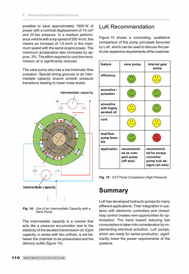
LuK Recommendation
Figure 15 shows a concluding, qualitativecomparison of the pump principals favouredby LuK, which can be used to discuss the par-ticular respective requirements of the customer.
Fig. 15: CVT Pump Comparison (High Pressure)
SummaryLuK has developed hydraulic pumps for manydifferent applications. Their integration in sys-tems with electronic controllers and closed-loop control creates new opportunities for op-timisation. The trend toward reducing fuelconsumption is taken into consideration by im-plementing electrical actuation. LuK pumps,which are ready for series production, signif-icantly lower the power requirements of thesystems.
feature vane pump internal gear pump
efficiency
acoustics / pulsation
acoustics with highly aerated oil
cost
dual-flow pump feasi-ble
application recommend-ed as com-pact pump (off axis)
recommend-ed for torque converter pump hub de-signs (on axis)

9 Demand Based Controllable Pumps
111LuK SYMPOSIUM 2002
References[1] Welschof, B.: Analytische Untersuc-
hungen über die Einsatzmöglichkeiteiner sauggedrosselten Hydraulik-pumpe zur Leistungssteuerung, Disser-tation RWTH Aachen 1995.
[2] Fassbender, A.: Theoretische und ex-perimentelle Untersuchungen an saug-seitigen Widerstandssteuerungen, Dis-sertation RWTH Aachen 1995.
[3] Keith, P.; Pask, M.; Burdock, W.: TheDevelopment of ACE for Discovery II,SAE Paper No. 00PC-60, 1998.
[4] Konik, D.; Bartz, R.; Bärntol, F.;Bruns, H.; Wimmer, M.: Dynamic Drive– das neue aktive Wankstabilisierungs-system der BMW Group, Proceedings9. Aachener Kolloquium Fahrzeug- undMotorentechnik 2000.
[5] Jost, K.: The ABC of Body Control, Au-tomotive Engineering International, July1999, p. 60 - 68.