Embed Size (px)
Citation preview

PUBLISHED PROJECT REPORT PPR689
Helmet Retention Report
S Jowitt, V St Clair, and A Osborne-Scott


Transport Research Laboratory Creating the future of transport
PROJECT REPORT PPR689
Helmet Retention Report
Stephen Jowitt, Vincent St Clair, Ashleigh Osborne-Scott
Prepared for: TRL, TRL Academy
Project Ref: 11112069
Quality approved:
Julie Austin
(Project Manager)
Andrew Parkes
(Technical Referee)
© Transport Research Laboratory 2014

PPR689 - Helmet Retention Report
Disclaimer
This report has been produced by the Transport Research Laboratory under a contract with TRF. Any views expressed in this report are not necessarily those of TRL.
The information contained herein is the property of TRL Limited and does not necessarily reflect the views or policies of the customer for whom this report was prepared. Whilst every effort has been made to ensure that the matter presented in this report is relevant, accurate and up-to-date, TRL Limited cannot accept any liability for any error or omission, or reliance on part or all of the content in another context.
When purchased in hard copy, this publication is printed on paper that is FSC (Forest Stewardship Council) and TCF (Totally Chlorine Free) registered.
Contents amendment record
This report has been amended and issued as follows:
Version Date Description Editor Technical Referee

Helmet RetCPR1825ion Report
Table of Contents 1 Introduction 4
2 Literature Review 4
2.1 Statistical data 4
2.2 Helmet effectiveness 5
2.3 Modelling collisions 6
2.4 Head shapes 7
2.5 Chin straps 8
2.6 Positional stability 9
2.7 Loss mechanisms 10
2.7.1 A failure to secure the helmet at all 10
2.7.2 A failure to secure the helmet properly 10
2.7.3 The use of an overly large helmet 10
2.7.4 A failure of the retention system 10
2.7.5 A failure of the retention attachment system 11
2.7.6 A user head profile that does not conform to the idealised form that is used in helmet retention tests 11
2.7.7 Wholesale destruction of the outer shell 11
2.7.8 A mis-match between head shape and helmet inner liner shape 11
3 Review of helmet standards 12
3.1 Motorcycle helmet standards 12
3.2 Dynamic test of retention system 14
3.2.1 ECE Regulation 22.05 14
3.2.2 BS 6658:1985 15
3.2.3 JIS T 8133 16
3.2.4 DOT FMVSS 218:2001 17
3.2.5 Snell M2010 17
3.3 Retention system detaching test 17
3.3.1 ECE Regulation 22.05 18
3.3.2 BS 6658:1985 19
3.3.3 JIS T 8133 19
1

Helmet Retention Report
3.3.4 DOT FMVSS 218:2001 19
3.3.5 Snell M2010 20
3.4 Discussion of retention system dynamic strength tests 20
3.5 Slippage of chinstrap through the fastener 21
3.5.1 ECE Regulation 22.05 21
3.5.2 BS 6658:1985 22
3.5.3 JIS T 8133 22
3.5.4 DOT FMVSS 218:2001 22
3.5.5 Snell M2010 22
3.6 Abrasion resistance of chinstrap 23
3.6.1 ECE Regulation 22.05 23
3.6.2 BS 6658:1985 24
3.6.3 JIS T 8133 24
3.6.4 DOT FMVSS 218:2001 24
3.6.5 Snell M2010 24
3.7 Minimum webbing width 24
3.7.1 ECE Regulation 22.05 24
3.7.2 BS 6658:1985 24
3.7.3 JIS T 8133 25
3.7.4 DOT FMVSS 218:2001 25
3.7.5 Snell M2010 25
3.8 Comment relating to chinstrap tests 25
3.9 Inadvertent release of chinstrap mechanism 25
3.9.1 ECE Regulation 22.05 26
3.9.2 BS 6658:1985 26
3.9.3 JIS T 8133 27
3.9.4 DOT FMVSS 218:2001 27
3.9.5 Snell M2010 27
3.10 Ease of release of chinstrap mechanism 27
3.10.1 ECE Regulation 22.05 27
3.10.2 BS 6658:1985 27
3.10.3 JIS T 8133 27
3.10.4 DOT FMVSS 218:2001 28
3.10.5 Snell M2010 28
2

Helmet Retention Report
3.11 Durability of chinstrap release mechanism 28
3.11.1 ECE Regulation 22.05 28
3.11.2 BS 6658:1985 28
3.11.3 JIS T 8133 28
3.11.4 DOT FMVSS 218:2001 28
3.11.5 Snell M2010 29
3.12 Comment on general functional requirements 29
3.13 Other general requirements 29
3.13.1 ECE Regulation 22.05 29
3.13.2 BS 6658:1985 30
3.13.3 JIS T 8133 30
3.13.4 DOT FMVSS 218:2001 30
3.13.5 Snell M2010 30
4 Practical testing 31
4.1 Regulation 22.05 Retention system detaching tests 34
4.1.1 Observations 35
4.1.2 Conclusions 36
4.2 Regulation 22.05 Quasi-static testing 40
4.3 Inertial loading tests 48
4.3.1 Observations 49
4.3.2 Conclusions 50
4.4 Snell stability test 53
5 User survey data 58
6 Conclusions 62
7 Bibliography 63
Appendix A Summary of Helmet Standard requirements 66
Appendix B How helmets fit the head 70
3

Helmet Retention Report
1 Introduction This study has two specific aims. The first is to see whether the existing test requirements in ECE Reg 22.05 relating to dynamic helmet retention (the roll off test) are realistically based and how well existing helmet designs comply with these tests when new and used. The second is to identify the mechanisms of helmet loss and to quantify the importance of relevant factors such as inertia effects, head geometry and flesh compliance and misuse.
2 Literature Review The importance of helmet retention throughout any collision is shown by the cost, to both the individual and society, in those cases when helmets are lost, exposing the head to the potential for significant head insult and long term injury.
The following sections discuss historic loss rates, helmet effectiveness (in terms of the potential reduction of harm), and the potential to use mathematical modelling techniques to identify the likely forces acting on the helmet in typical real world collisions.
2.1 Statistical data The majority of technical reports available on helmet use and performance concentrate on their protective properties during the collision phase from an experimental or theoretical approach (typically using computer modelling). These approaches are only effective if the helmet has been retained on the user’s head, a factor that has been explored by a small number of real world studies. This section explores the data that is available about helmet loss.
This has to be preceded by a word of caution, in that helmet standards, and thus helmet construction, are not uniform throughout the world, and there are some helmet types that have not been constructed so as to limit the potential for loss, and there are some helmet types that are known to be more prevalent to loss. Some of these studies attributed loss to particular causes, something that is addressed later in this document.
A Japanese study (Nakamura, 1973) analysed 21 collisions where the helmet was available for inspection. In 5 of these the retaining strap was shown to be undone, or else failed, and there was one confirmed ejection.
Larder (1984), summarised real world data collected by others at the accident Research Unit at the University of Birmingham in 1984. Of 78 casualties in serious injury motorcycle accidents there were 8 losses (helmet ejections), of which 3 were without known cause. 2 were assigned to improper strap use, one to strap failure, and 2 to incorrect sizing.
The MAIDS study in Europe (2004-2008) analysed 921 riders and 48 pillions. The loss rates in collisions were 11% for both user types where helmet use was known. The major cause of ejection was established as improper fastening or alteration (68%). Ejection through helmet failure was only 1%.
A study in Thailand (Kasantikul, 2001) suggested rider loss at about 23% and pillion loss at about 20%. User misuse (defined as failure to secure) was established at 85% as a causal factor.
4

Helmet Retention Report
A Japanese study from 2002 (ITARDA Information, 2002) established a slip off rate of about 19%, with 56% of these being unfastened. A follow up study from 2006 (ITARDA Information, 2006) showed a reduced rate of slip off at 7%, with 83% being unfastened. About 2% of those ejected were shown to be fastened, but this varied amongst helmet styles. There was a defined link between ejection rate and speed, as well as between ejection rate and fatality.
The COST 327 (2001) study, based on hospital admissions in Glasgow, Hannover and Munich, showed that 17 out of 90 helmets were lost at the interim reports stage.
A large review of helmet performance in both Los Angeles and Thailand (Ouellet & Kasanitikul, 2006) showed a loss rate of 5% and 21% respectively.
A recent World Health Organisation document on helmet use (WHO, n.d.) suggests a loss rate of 6% to 9% in the UK.
A TRL Report (Smith, Knowles & Cuerden) that analysed Police Collision files for fatal motorcycle accidents in London between 2006 and 2009 suggests that 17 helmets were lost in 94 collisions. An in-depth study of the files showed that there were 7 losses, of which 5 were insecure.
Mills & Ward (1985) cite other studies suggesting a loss rate of between 10% and 30%, although before a dynamic retention requirement was included in the Standard in the UK.
Whilst it is not possible to aggregate these data sources to provide an overall rate (either for the UK of for all helmet users) a value of around 5% does not appear unrealistic for real world conditions.
2.2 Helmet effectiveness The potential loss of a helmet in a collision would be of no real importance if they were shown to be of marginal effectiveness even when retained; it is thus of importance to establish metrics of effectiveness. Although this has been reported in a variety of ways in the published data, much of it is without statistical validation. The data sources below are not exhaustive, but are intended to show a range of activity from around the world.
The study in Los Angeles and Thailand (Ouellet & Kasanitikul, 2006) was extended to analyse effectiveness. Non-helmeted riders were found to be 2 to 3 times more likely to be killed, although this ratio must encompass other forms of risk acceptance other than helmet use. Of those collisions that were deemed survivable, universal (correct) helmet use was predicted to have prevented 80% of both brain injuries and fatalities.
An Oxford Review of data in 2004 (Philip, Fangham, Liao, Lilienthal & Choi, 2013) suggested that helmet use would halve the risk of death, and cited an NHTSA value of 29% for a reduction in death. That NHTSA data (up to 1989) was raised to 37% using data from 1993 to 2002 (NHTSA, 2004).
The IIHS-HLDI (Huang & Preston, 2004) published data showing that helmet use reduced head injury by 69% and fatality by 42%.
A hospital based study in Jamaica (Crandon et al, 2009) evidence that there was a 40% reduction in mortality risk and 70% reduction in risk of head injury. Local data showed significant reductions in all levels of brain injury and mortality.
5

Helmet Retention Report
A study in Michigan from 2002 showed helmet use to reduce mortality by 39%, and risk and severity of injury reduced by 72%. This document shows other links between helmet use and injury prevention.
These data sets are among a large number that show a strong correlation between helmet use, mortality and head injury reduction. Head injuries are very expensive to the individual, their family and immediate community, as well as nationally.
A severely brain injured person will need a large amount of support to achieve a decent level of lifestyle, and this may be for a considerable period if the injury is caused in the adolescent period, as is typical of many motorcycle users.
Accordingly correct helmet use and effectiveness are critical to the potential reduction of both individual and societal costs.
2.3 Modelling collisions There has been criticism that the current regime of statutory helmet impact tests produce helmet designs that are too stiff for the majority of real world head insults; this has led to the development of the SHARP helmet assessment program, where impacts of lower and greater magnitude are assessed.
There are potentially two approaches to analysing the real world energy absorbing capabilities of helmets, firstly by studying and replicating particular collisions in the laboratory, and secondly by the adoption of computer modelling. This second approach also has a greater potential for analysing the forces that are likely to cause a helmet loss, and thus the tests that ought to be adopted to lessen this potential.
Otte (1997) studied 876 collisions and defined the contact partner. 52% of the collisions occurred with cars, and 35% with other structures. The collisions were also divided into seven defined collision types described in the paper, showing the direction and part of the collision partner. One third of collisions involved speeds above about 30 mph.
Otte (2006) continued his studies and in 2006 published data that related projected distance with impact speed, relating his defined seven collision types with those defined in ISO classification 13232-2. Head injuries were more likely to occur when colliding with the sides of cars.
A number of attempts have been made to model motorcycle to car collisions to try to establish metrics for severity. At the most basic level, summation of the crush depth of the car and the reduction in length of the motorcycle has shown to correlate to closing speed, but with wide variation. More meaningful reconstruction attempts have been made to reconstruct staged collisions (such as Deyerl, 2008) to try to match impact speeds with collision damage and post impact movement.
These attempts have been enhanced by understanding the crush and dynamic performance of motorcycles beyond the simple crush model (as in Nieboer, 1993), and this has been extended to very detailed models of motorcycles (Deguchi, 2003) in collision with cars (Deguchi, 2005) to produce very high levels of fidelity when compared to staged collisions. This form of modelling extends to the trajectory of the rider, although matching rider dynamics has proved difficult.
6

Helmet Retention Report
Helmet modelling commenced with simple camera matching and accelerometer exercises (Zellmer, 1993), to gain an understanding of helmet stiffnesses in the regulatory tests. This was to analyse the criticism of Reg 22 helmet performance.
These simple modelling exercises were overtaken by far more sophisticated studies (Bourdet, 2010) to analyse helmet performance in real world collisions. It has been suggested (Fernandes, 2013) that the modelling has now reached such a stage that it could be used to become the format for acceptance under Reg 22, instead of physical testing.
The model has been extended to include a model for the head and brain, so that a greater understanding of internal injury could be developed, instead of the crude whole (rigid) head injury metrics used currently. This form of modelling (Unknown, 2008) includes the loads on the retention strap, but has not been extended to rotational (roll off) retention questions.
The potential for computer modelling of helmet performance was discussed in the Cost 327 Report of 2000 (COST 327, 2000), using a gap between the helmet and the head shape, and the form of acceleration profile matched experimental data for a conventional frontal impact.
It was this modelling that led to the development of the later models as computing power and models became cheaper and more readily available.
At present, retention tests are conducted using impulsive loads derived from a weight falling down a set distance, and it is difficult to determine whether these tests are representative of any real world circumstances. Mills suggests an average head deceleration of 20 g, so that a 1.5 kg helmet would be exposed to a linear force of 300 N. Hurt suggests that the value may be up to 40 g, thereby doubling this load.
But as the nature of the load is dynamic, it may be the jerk, or impulse, (expressed as metres per second cubed) that is critical to the initiation of helmet loss, in the same way that it relates to the stability of passengers on public transport when there is sustained and rapid deceleration.
2.4 Head shapes Whilst helmets have to be defined by uniformity of production, head shapes are many and varied, and that is something that has been recognised by a number of manufacturers. This is an aspect that will be discussed later in this report.
The modelling of the forces, and thus potential injuries, within the brain, are dependent on the coupling of the head shape to the internal shape of the helmet. It is not possible to define a head shape uniquely by a few measurements or ratios, and even if it was it would not be possible to provide an infinite variety of helmet inner shapes for each notional head size to try to optimise the coupling between helmet and head.
It is now possible to measure head shapes to a very high level of precision, on the basis that they are invariant (that is to say that heads do not deform under impact loads). This has been described in a number of technical papers, for example Gilchrist, Mills & Khan, 1998; Carnicky & Chorvat, 2006; Koyasu, Amano & Sato, 2007; Haiyan et al, 2007. This has proved important to the manufacturers of PPE (Personal Protective Equipment) when venturing into markets where the head shape may be defined by strong regional or racial characteristics.
7

Helmet Retention Report
The use of CT (Computed Tomography) to analyse helmet liner crush was discussed by Loftis et al (2011), and this method is used routinely by specialists to detect and define internal brain injury. It can also show external head shape after insult.
Helmet designs are tested on defined head shapes, which may not conform to those regional or racial characteristics, and thus may not provide optimum protection. This is potentially true of the roll off test, which is a measure of quality of fit as much as any other variable.
The defined head shapes are constructed from rigid materials with no conformal surface to replicate skin or fat, and with a rigid jaw. The hair piece is ill defined and is unrelated to natural hair. In all, it is high likely that these defined head shapes bear little resemblance to the wide range of potential user shapes.
Gilchrist, Mills & Khan (1998) analysed this in depth, but there does not appear to have been any particular discussion of this problem after this.
2.5 Chin straps Analyses of helmet losses before the introduction of BS 6658 indicated that many of the losses could be attributed to the chin straps being attached to the outer shells at positions that could little resist rotation of the helmets, even when the straps were tight.
There are few variations within chin strap designs now, and most are attached with metal straps that are riveted to the outer shell, and connect together below the chin either with a double D linkage, which is self-tightening under load; a sliding bar mechanism, again self-tightening; or a small quick-release buckle, which is designed to resist inertial and accidental release.
Whilst it is possible to define a large number of variables in relation to helmet retention, it is not possible to define strap tightness. There are many industries where strap or cable tension is critical, and a number of specific tools have been designed to assess that tension, often in the form of a three point of contact tool, where the bending load in the tool is a proxy as a measure of tension.
It is not possible to use this form of device to determine helmet strap tension, often because the strap is not tightened fully. This is an aspect that was addressed in our user survey, and reported later. Many helmet users allow a small amount of slack in the strap below the chin, although this may cause the helmet to lift at speed as a consequence of aerodynamic lift acting over the crown of the helmet. Whether this occurs depends on the snugness of fit, and may be reacted by chin pads if fitted close to the side of the face. But even if the chin strap is tightened, the length of straight strap available is very limited, so restricts the use of such a device.
The strap tightness is defined by the compression of the flesh below the chin, and this may have to be extensive in users with large jowls. It appears the only realistic way to measure a function of strap tightness, which can include a measure of excess slack, would be to use the form of tapered rod that is used by jewellers to define ring size.
8
Helmet Retention Report
But as the gap is not defined by solid sides, but rather it is defined by conformal structures (the strap on one side and the fleshy part of the chin on the other) a limit value of force to introduce the tapered rod would be necessary. This would then allow a specific level of slack to be defined when replicating helmet losses on a retention rig.
This is an aspect that currently lies outside the scope of this report, but is considered to be an important aspect of analysis that should be explored in greater depth, given the user responses.
2.6 Positional stability Helmet loss and ejection is related to positional stability. In the British Standard the acceptance criteria was for helmet retention, whilst the ECE Regulation calls for a static rotation of no more than 30 degrees. That value is measured after the weight has descended and its effect reacted by resistance and rotation of the helmet. Dynamic studies included in this report show that the actual peak rotation of the helmet exceeds this value, and that there is both permanent and elastic response to the inertial load. This means that the reaction of the helmet, in rotation, to the imposition of the load cannot be described simply by a value of stiffness.
Mills & Ward (1985) describe the development of the retention test within BS 6658, and initial testing of helmets that were manufactured without regard to the new standard.
In a second paper Gilchrist & Mills (1992) report tangential forces in the roll off tests of about 500 N and say that the BS 6658 retention test was based on inertial rolloff, not contact. Contact with a car or road surface could generate a tangential force of the order of 1000 N to 1500 N, far higher than the test requirement.
The ability for a helmet to resist roll off is dependent upon the fit of the helmet to the nape of the neck and then the rear of the skull; whereas a typical cycle helmet, with a Y shaped yoke on either side of the helmet, has an additional strap element (something introduced into one modern motorcycle helmet design).
Gilchrist & Mills suggested that the retention standard should be rewritten to increase the tangential force to 300 N, by incrementally increasing the distance over which the falling weight was dropped.
Hurt also co-authored two papers on this subject, the first in 1998, documenting a series of simple drop tests with a range of helmets. The testing also included volunteer tests with the volunteers pulling the helmets themselves. The partial coverage (half helmets) units showed a high propensity to roll off, whilst the choice of headform (ISO or DOT) altered the potential for rolloff of the other helmet styles.
This data is explored further in Hurt, Thom, Smith & Ouellet (1997), and suggests a potential ejection rate of between 1% and 90%, as compared to the real world data value of about 5% discussed previously.
Research in Australia on both cycle and motorcycle helmet stability (Thai, Pang, McIntosh & Schilter, 2009) showed that many helmet users were not able to judge helmet size correctly, with only 40% choosing correctly. Forward helmet rotation of 10 degrees was achieved with only 18 N (force) for open face helmets and 30 N for full face units.
9
Helmet Retention Report
A second paper (Thai, Pang & McIntosh, 2009) found that the force required to rotate helmets by small amounts (about 5 degrees) on seventeen adult volunteers was not significantly different between correct and incorrect sized helmets. The helmets were seen to be displaced at significantly lower loads on the humans than on the test headforms.
Research at TRL (Mellor, St Clair & Chinn, 2007) based on a sample of 10 volunteers showed that 4 could be removed by roll off as the chin strap was so loose that it could pass forward beyond the chin.
2.7 Loss mechanisms From the foregoing it is apparent that there are a large number of potential loss mechanisms, and these are listed below, although in no particular order of importance.
2.7.1 A failure to secure the helmet at all
When a powered two wheeler user collides with another object it is common for the rider to be projected. In many such cases the projection is forwards, but as the lower half of the rider is likely to strike the handlebars, or some part of the struck object, the projection will involve some form of head down rotation as well as deceleration. The combination of these two aspects will cause the helmet to try to lift off the user’s head, as well as to rotate forwards – tendencies which should be resisted by the retention device. If there is no retention the helmet has a higher likelihood of being ejected.
2.7.2 A failure to secure the helmet properly
The helmet retention depends on the retention device being secured correctly around the user’s neck, usually as a strap passing below the chin. It is reasonably common to see this strap to be loose, and hence not able to resist the first parts of helmet lift and rotation. If the retention strap is too loose it has potential to swing forwards, clear of the underside of the chin, so as to serve no useful purpose.
2.7.3 The use of an overly large helmet
Retention relies on the helmet being a correct fit to the head. The use of an overly large helmet can create large gaps between the inner lining and comfort padding and the user’s head, and also potentially position the chin strap too far forwards. These factors may combine to make the helmet more likely to be ejected.
2.7.4 A failure of the retention system
There are traditionally two forms of retention system, the sliding bar type and a small tongue and latch quick-release combination, similar to that employed with seat belts. Sliding bar systems are generally fault free other than for possible webbing abrasion, as they do not contain any stored energy elements (springs) which can break or degrade. Quick release systems can however become faulty and jam, and may be prone to false latching if internal wear becomes excessive. They are produced to resist inertial and accidental release.
10

Helmet Retention Report
2.7.5 A failure of the retention attachment system
The webbing systems are often sewn to steel plates which are secured to the outer shell by mechanical fasteners. There are physical limits on the types of fasteners that can be used, as these should not be capable of generating point loads on the head if the impact occurs adjacent to their location. In general the form of fastening consists of rivets, normally as a pair so as to resist rotation of the plates. If the stitching or mechanical fastening fails or is significantly degraded, the retention system is negated, which may lead to loss.
2.7.6 A user head profile that does not conform to the idealised form that is used in helmet retention tests
Of particular note are head shapes with little or no chin profile, below which the retention strap should nestle. As a consequence the chinstrap may easily slip forward and away from a position that would ensure effective operation.
Head shapes that are flat at the back may also present additional risks of ejection since the inner liner sits well clear of the scalp. The nape of the skull would therefore present reduced resistance to rotation to the back of the helmet.
Hair should also be considered as a head geometry factor that can affect fit. Large volumes of hair within the helmet can change the perception of good fit to the rider and also present limited support and resistance to helmet movement during a dynamic loading event.
2.7.7 Wholesale destruction of the outer shell
If the outer shell is compromised, as a consequence of physical degradation and impact force, the whole of the outer shell may split, allowing for helmet loss. This is a very rare occurrence since helmet design is aimed towards preservation of the shell as a whole (i.e. there are no sacrificial components) and the surface area of the protected region is constructed as a single unpierced piece (other than for small ventilation holes).
2.7.8 A mis-match between head shape and helmet inner liner shape
Helmets are produced to given sizes that are defined by a circumferential measurement around the major diameter of the user’s head. Whilst there are precise dimensions for the variety of head forms that are used within the regulatory testing regimes, there are none for the inner surfaces of the inner energy-absorbing liners.
The inner liner is relatively stiff so that it can manage the designated impact energy. As a consequence it retains its shape in general use. But, since every head shape of a given size will be somewhat different, no mass produced inner liner will fit exactly to every head. Manufacturers resort to the use of comfort lining within the helmet to make a better fit.
Furthermore, manufacturers do not produce a different outer shell or inner lining for each defined head size. Helmets tend to be marketed in 2 cm circumference bands, from 56 cm (small) to 62 cm (XL), other than for children, and may be based on one or two outer shell sizes, and probably 2 inner lining sizes. There are also helmets made specifically for children, ranging from XXXS (49-50 cm) to S (55-56 cm), and some adult ranges extend to XXL (63-64 cm).
11

Helmet Retention Report
To fill the gap between the smallest and largest sizes in a single inner liner size, comfort foam of up to 1 cm thickness may be used. This foam is much softer than the energy absorbing inner liner and deforms readily when compressed. As a consequence, a head/helmet size and shape mismatch may create a condition where a helmet with a notionally good static fit becomes one with a poor dynamic (impact) fit, leading to increased risk of loss.
A further concern is that, open-cell foams typically used for comfort padding bands within the inner liners often suffer from deterioration or relaxation from aging or use, such that helmet fit may worsen with extended use or age.
As part of this study a number of helmets were sectioned and then photographed on a size 57 test headform. The photographs of these sectioned helmets show that they possess significantly different internal profiles that are likely to be responsible for different values of stability.
Mills (1996) suggests that the grip resulting from the contact between the rear of the helmet and the user’s neck can only resists 500 N, whereas a sliding contact can produce a tangential load of 1000 N. (Note: test results within this document suggest that the value may be less than 500 N).
Therefore a helmet with only a single strap may not be able to prevent rolloff if there is external contact, and this is probably more important with ¾ or jet style helmets.
A recent symposium (Halldin & Kleiven 2013) suggested that helmet designs should incorporate a new oblique impact test based on real world experience, and that helmet and restraint fit, and head shape and size would need to be evaluated for this. Any new oblique test, if applied upwards at the rear, or downwards at the front, could alter the requirements of a retention test.
3 Review of helmet standards A review of the standards associated with motorcycle helmets has been completed. The significant performance requirements have been reviewed together with any prescriptive requirements that may affect the retention of the helmet on the head. A range of standards have been reviewed to understand any significant similarities or differences between them. This review considers chinstrap retention systems only (as opposed to closure mechanisms).
3.1 Motorcycle helmet standards Motorcycle helmet legislations vary around the world with most countries mandating the use of a helmet for use on a powered two wheel vehicle. However, some areas do not mandate the use of helmets, for example some states in the USA, and others have a more relaxed attitude to the standard of helmets used. Some parts of South America for example mandate helmet wearing but do not prescribe a standard for the helmet.
A number of differing standards exist, some of which are suited to a particular country. For example, the Japanese standard JIS T 8133:200 includes a lightweight half face helmet (see Figure 3 for reference).
12

Helmet Retention Report
The following standards have been identified as relevant for motorcycle helmets globally:
• Australia AS 1698-2006
• Brazil NBR 7471
• Canada CSA CAN3-D230-M85
• India IS 4151
• *Japanese: JIS T 8133:2007
• Korea KS G 7001
• Malaysia SIRIM
• *New Zealand NZ 5430
• Singapore PSB
• *Snell M2010
• Taiwan CNS
• Thailand TIS
• *UN ECE Regulation 22.05:2002
• *UK BS 6658:1985
• *USA: DOT FMVSS 218:2012
However, only those marked with an asterix have been reviewed as part of this project, with a focus on the United Nations ECE Regulation 22.05 due to its relevance to the UK and European market.
This review identifies the tests prescribed by the regulation used to evaluate retention systems and generally considers their suitability at ensuring protection against helmet loss. Further standards are reviewed to see how they compare to EC Reg 22.05 and whether any significant differences exist that could be relevant for retention performance.
The UN ECE Regulation 22.05 came into force in June 2000 as the accepted European regulation for motorcycle/moped helmets. The 22.05 amendment incorporated aspects of some remaining localised standards, such as BS6658:1985 in the UK, to ensure harmonisation of these standards with minimal compromise to safety. The new regulation allowed manufacturers better opportunity to trade fairly across Europe with a single helmet design.
Helmets conforming to Regulation 22.05 now represent the majority of sales of helmets across Europe and Reg 22.05 is also the basis for other standards globally.
13

Helmet Retention Report
The regulation provides a comprehensive range of conditioning, impact, geometrical and performance requirements, some of which are focused specifically on the helmet retention system. These include:
• Dynamic test of retention system §7.6
• Retention system detaching test §7.7
• Microslip of chinstrap §7.9
• Abrasion resistance of chinstrap §7.10
• Chinstrap strength §7.11
• Test of quick release mechanism
Inadvertent release §7.11.1
Ease of release § 7.11.2
Durability of release mechanism §7.11.2
These requirements are further considered herein, with reference to other international standards to identify key requirements of the standards across the world.
Appendix A contains a tabulated summary highlighting the key requirements of each standard for whole system, chinstrap and release mechanism.
3.2 Dynamic test of retention system Tests of the complete retention system are specified to ensure appropriate strength and design of the restraint system and compatibility with the helmet to which it is fitted. For Regulation 22.05 two tests are prescribed to ensure adequate dynamic strength and helmet stability performance.
3.2.1 ECE Regulation 22.05
UN ECE Regulation 22.05 prescribes a dynamic test to evaluate the in-situ strength of the entire retention system, including the helmet anchorage interface.
The test is completed on a full new helmet to which a solvent has been applied. In approval testing, the helmet is chosen of a size that offers the least favourable conditions, for example, the helmet with the thickest comfort padding in the size range.
During the test, the test helmet is suspended from its top and a rigid headform fitted. The headform is attached to a rigid arrestor/anvil directly below (see Figure 1). The mass of this arrestor/anvil is 15 ±0.5 kg (including headform). The arrestor/anvil provides a pre-load to the helmet to ensure good fitment of the helmet on the head but also generates pretension in the chinstrap.
14

Helmet Retention Report
Figure 1 – Reg 22.05 Retention test equipment
A falling mass is then released to strike the arrestor/anvil directly below the headform. This provides a dynamic loading event, effectively trying to pull the headform down and out of the helmet. At least 72.4 J of kinetic energy is provided to the headform in this way as the rigid falling mass of 10 ±0.1 kg falls 750 ±5 mm.
During the test the deflection of the headform is recorded. The dynamic deflection of the headform must not exceed 35 mm and the residual deflection, after 2 minutes with the 15kg ±0.5 kg still attached, shall not exceed 25 mm. Failure to the retention system is allowable provided that the helmet can be removed easily e.g. quick release mechanisms can be operated effectively.
A further requirement of this test is that the chinstrap shall have a minimum width of 20 mm at the pre-release (15 kg) pre-loading condition.
3.2.2 BS 6658:1985
The BS 6658:1985 standard presents an alternative dynamic-loading test method to Regulation 22.05 with a direct load path to the chinstrap via a chinstrap ‘stirrup’. The stirrup is attached to the falling weight arrestor system with a 10 kg mass falling 750 mm; similar to that of Reg 22.05, but incorporating a small polyurethane damping foam pad device that absorbs some of the initial shock load (see Figure 2).
15

Helmet Retention Report
Figure 2 – BS 6658 Retention test equipment
The BS method supports the helmet around the rim which, like Reg 22.05, may not represent a real world loading condition but does reduce the influence of helmet shell deformation that may influence energy absorption and the load exerted to the chinstrap. Nevertheless, the method appears simple and, other than the foam pad, appears a repeatable and reproducible apparatus and methodology.
The most significant difference to Regulation 22.05 is that BS 6658 includes a double loading with a requirement of 32 mm and 16 mm for dynamic and residual displacement respectively for the first test and 25 mm (dynamic) and 8 mm (residual) for the second.
3.2.3 JIS T 8133
JIS T 8133 presents two methods for dynamic strength testing, based on BS 6658 and Regulation 22.05. The different helmet types referred to in this standard are shown in Figure 3 below.
For JIS T 8133 type 2 helmets (open face and full face) the apparatus and test methods are comparable to the BS 6658 (750 mm, 10 kg) and Regulation 22.05 (750 mm, 10 kg) requirements except that preload is 10 kg and the limits are 35 mm for dynamic and 25 mm for residual deformation.
The use of the two methods with the same input energy and deflection limits, suggests that the methods are closely comparable. However, it may also indicate that BS 6658 may be slightly more stringent than Regulation 22.05 as the BS only permits 32 mm for the dynamic displacement for the first test compared to 35 mm.
16

Helmet Retention Report
An important difference with JIS T 8133 is that Type 1 helmets (half face and three quarter face) have much lower dynamic loading energy levels of 10 ±0.1 kg at 240 ±5 mm. This energy level is more than 3 times lower than Type 2 helmets.
Figure 3 – JIS T 8133 helmet types
3.2.4 DOT FMVSS 218:2001
DOT FMVSS 218:2001 does not prescribe a dynamic retention strength test. However, a quasi-static load test is prescribed. The test is alike that of the dynamic retention system test defined by BS 6658 and Snell M2010 but instead a load is applied directly to the chinstrap quasi-statically. The load of 22.7 kgf is applied at a rate of 1 mm/s to 3 mm/s and held for 30 seconds and then an additional 113.4 kgf is applied for 120 seconds. Following the load application the adjustable portion of the retention system test device shall not move more than 25 mm.
3.2.5 Snell M2010
Snell M2010 adopts a test method comparable to BS 6658, with the helmet supported on its rim and headform to be dynamically loaded by a falling mass through a chinstrap ‘stirrup’ arrangement. The stirrup, as for BS 6658, is considered to represent the jaw geometry.
The impact energy is at least 44.1 J with a 38 ±0.5 kg falling at least 120 mm. The maximum allowable dynamic deflection is 30 mm. This energy level is lower than that prescribed by the BS 6658 and Regulation 22.05 standards.
3.3 Retention system detaching test The retention system detaching test is sometimes known as the ‘positional stability’, ‘Pull off’ or ‘Roll off’ test, as the test is effectively trying to make the helmet unstable and pull or roll the helmet off the test headform.
17
Helmet Retention Report
This action of removing the helmet by rotation is generally regarded to be a good indicator of helmet fit and chinstrap effectiveness. Advice from consumer information schemes such as SHARP illustrate how the helmet should be pulled forward from the rear to ensure that visibility is not obscured and the helmet cannot be removed with the chinstrap fastened.
3.3.1 ECE Regulation 22.05
The test is completed on a full new helmet to which a solvent has been applied. In approval testing, the helmet is chosen of a size that offers the least favourable conditions. For example, helmet with the thickest comfort padding. The helmet is pre-marked with a reference line in the same plane as the reference line of the test headform.
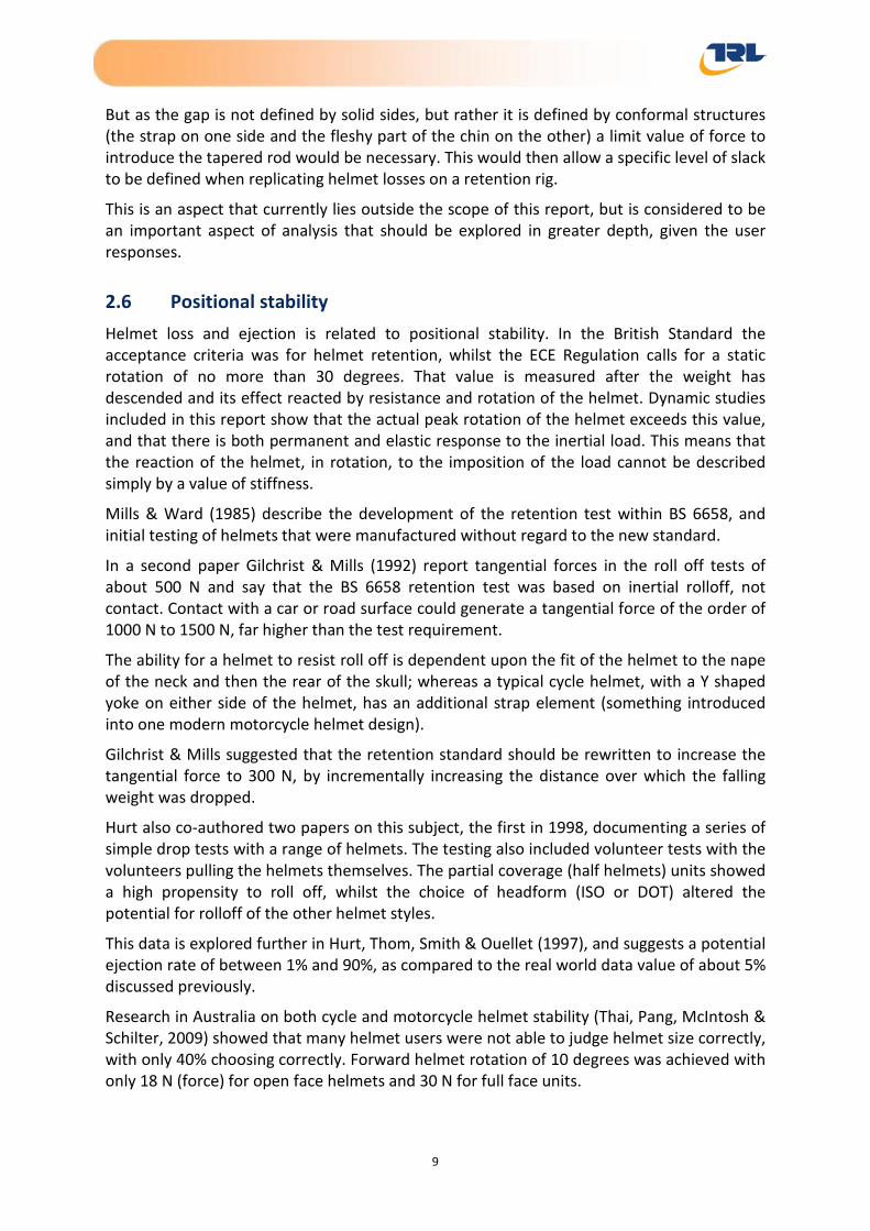
The helmet is fitted securely to an appropriately sized test headform which is rigidly attached to a test bench with a base >100 mm tall (see Figure 4). A falling mass guide frame of total mass 3 ±0.1 kg is attached to the rear of the helmet using a steel rope and rigid hook. The frame is then suspended from a 100 mm diameter pulley that is 45° forward and 600 mm up from the headform centre. The frame provides a pre-load to the helmet and retention system to ensure good fit and removes any slack in the retention system.
Figure 4 – Regulation 22.05 Detaching test apparatus
A falling mass is then released to strike the frame attached to the helmet. This provides a dynamic loading event to attempt to tug the helmet forward and off the test headform. At least 48.0 J of kinetic energy is provided to the helmet, with the rigid mass of 10 ±0.01 kg falling from a height of 0.5 ±0.01 m.
After the impact, the helmet rotation forward is recorded by measurement of the angle between the reference plane on the helmet and that on the headform. For approval tests the maximum allowable rotation angle is 30°.
18

Helmet Retention Report
3.3.2 BS 6658:1985
BS 6658:1985 prescribes an alternative retention effectiveness test method to that of Regulation 22.05. The principle is similar with a dynamic loading event pulling the helmet from rear to front but the central longitudinal axis of the headform is inclined at 45° (facing down) and no pulleys are used to connect to the falling mass (see Figure 5).
In addition, the headform includes a deformable chin section and 70mm length wig. The deformable chin and wig are designed to provide compliance to the chin and lower friction to the headform that may be expected on a human head.
The 4.0 +0.2/-0 kg drop weight is allowed to fall 1.0 +0.1/-0 m and provides at least 35.0 J of impact energy. The helmet should be retained on the headform to achieve a pass results in this test. Only size K (580 mm) helmets are tested on a size G (XXX mm) headform.
Figure 5 – BS 6658 Helmet stability test apparatus
3.3.3 JIS T 8133
The test prescribed by JIS is identical to the European regulation with identical equipment and drop heights for Type 2 helmets. However, there is no restriction on the amount of rotation and instead the helmet need only be retained on the test headform.
For Type 1 helmets the drop height of the 10.0 ±0.1 kg falling mass is reduced to 175 ±5 mm from 500 ±10 mm representing approximately one third of the impact energy. Tests are also completed on the smallest appropriate headform for the given size range.
3.3.4 DOT FMVSS 218:2001
DOT FMVSS 218:2001 does not prescribe a stability test.
19

Helmet Retention Report
3.3.5 Snell M2010
The test configuration is similar to BS 6658 with a test headform orientated at 45° facing down. However, the headform is rigid without either a wig or foam chin. The helmet must be retained on the headform when subject to a 4.0 ±0.05 kg load through a 600 mm drop. This is approximately 40% less energy than prescribed by BS 6658. Unlike BS 6658 the tests are completed on different of helmet sizes using the smallest appropriate headform for the helmet size range.
Perhaps the most significant difference of Snell M2010 and the other standards reviewed here is that the helmet is tested in two directions; pulling from the rear forwards and from the front rearwards.
3.4 Discussion of retention system dynamic strength tests The inclusion of a whole retention system strength test (static or dynamic) in all of the standards reviewed suggests that loading of the helmet restraint is of significant importance to restraining the helmet in an impact event. Similarly the inclusion of the helmet stability test, in all but one of the standards, illustrates that helmet fit and the mechanisms of helmet loss are of particular significance.
The methods prescribed for strength testing represent improbable loading conditions in real world accidents. A direct pull on the chinstrap would only occur if the helmet was snagged and the body retained inertia in an opposing direction. In such cases it may actually be beneficial for the strap to fail rather than throttle the rider. Loading on the chinstrap is considered to be most likely to occur from rotation of the helmet on the head due to oblique impact loading or inertia of the helmet.
The stability test is therefore complementary to the strength test and addresses the more probable scenario where the helmet is impacted and produces a tangential load to rotate the helmet around the head. In all the stability tests reviewed, rotation will generally occur about a centre close to where the chinstraps are typically anchored so may not necessarily produce large chinstrap load.
There is however some perceived failings of the test methods described. The stability test does not fully account for the diversity of head sizes, head shapes or compliance of the chin that helmet wearers have.
Fit issues are, in part, addressed by use of ‘worse case’ conditions, for example using the smallest test headform for a helmet size range. The BS standard does go further to include the use of deformable chin and wig to represent the compliance of the human head in the test headform. However, the headform remains rigid in the nape and crown where the geometry is fixed and the liner loads against the headform. For this reason it is perceived that it may be still be possible to achieve a pass result in the tests by the helmet ‘locking’ against the headform due to close fitting headform geometry.
20

Helmet Retention Report
The significance of helmet inertia, deformation and changing load paths that may occur during an impact event are not addressed by the test methods reviewed. Indeed the tests generally prescribe loading conditions in one plane, forwards or rearwards, which both rotates and lifts the helmet from the head providing some tension in the chinstrap. In real world impacts, rotation could occur due to tangential impact loading on the shell whilst the helmet is also pushed onto the head; the chinstrap may not therefore resist this rotation in the same way.
The load conditions could also be varied by articulation of the human neck which could allow, for example, contact of the chinguard with the sternum, creating a pivot point thereby influencing the rotation, chinstrap loading or helmet inertia. Again, the geometry and fit of the helmet on the head will influence the ability to retain the helmet.
The observations of possible deficiencies are speculative and further investigation of the head geometry, inertial affects and load directions is therefore recommended to understand the appropriateness of the standards’ tests.
In terms of the most severe tests reviewed, Regulation 22.05 appears to provide the most severe strength and stability test conditions with the greatest impact energies but it omits the front pull test prescribed by Snell and the deformable elements of BS standard that appear relevant to real world accidents.
3.5 Slippage of chinstrap through the fastener The performance of the chinstrap alone is considered in many of the standards to ensure continual correct functioning of the restraint system. This includes measures to ensure slippage and durability of the webbing materials and adjustor mechanisms.
Typically endurance (cyclic) testing is prescribed to ensure to simulate wear and tear and strap loading that may occur due to movement of the helmet on the rider’s head during normal riding, such as through cornering and air buffeting.
3.5.1 ECE Regulation 22.05
Regulation 22.05 defines a test to ensure that slippage of the webbing through adjustable parts of the restraint system is not excessive, ensuring that the helmet will not become loose during normal wearing.
The test is completed on a new sample of the helmet chin strap of at least 300 mm length including any adjustors and fastenings. The strap is attached to a static weight such that it generates a 20 ±1 N tension on the strap when lifted. The strap is then passed over a pulley (of maximum diameter 20 mm) and fixed to an actuator horizontal to this pulley. The actuator can be operated with a reciprocating motion over a stroke of 50 ±5 mm at a frequency of 0.5 Hz and 2 Hz.
By adjustment of the chin strap the apparatus is configured so that, at the maximum stroke of the actuator, the mass is lifted 25 ±2.5 mm from a rigid surface. As the minimum stroke of the actuator is achieved the mass is supported by the surface with 25 mm of slack in the chin strap (see Figure 6).
21

Helmet Retention Report
Figure 6 – Regulation 22.05 micro-slip test apparatus
The test commences with a total of 20 cycles lifting the mass before marking the initial strap position through the adjustors. A further 500 cycles are completed and the distance through which the strap has slipped is recorded.
The total permitted slippage of the chinstrap is 10 mm.
3.5.2 BS 6658:1985
BS 6658:1985 includes the same tests as prescribed by Reg 22.05.
3.5.3 JIS T 8133
No slippage requirements are defined.
3.5.4 DOT FMVSS 218:2001
A quasi-static load test is prescribed by FMVSS 218. The test is similar to that of the whole-system dynamic strength test defined by BS 6658 and Snell M2010 but instead load is applied quasi-statically directly to the chinstrap. The load of 22.7 kgf is applied at a rate of 1 mm/s to 3 mm/s and held for 30 seconds and then an additional 113.4 kgf is applied for 120 seconds. Following the load application the adjustable portion of the retention system test device shall not move more than 25 mm.
3.5.5 Snell M2010
No slippage test is prescribed.
22

Helmet Retention Report
3.6 Abrasion resistance of chinstrap The action of tightening a chinstrap will inevitably create friction about hard points on the adjustor and potential to abrade the webbing causing wear. Wear can result in exaggerated slippage around fasteners or possible failure of the webbing and is therefore an important aspect of the chinstrap performance. An abrasion resistance test can help to ensure that the webbing has adequate resistance to abrasion.
3.6.1 ECE Regulation 22.05
The abrasion resistance test specified by UN ECE Regulation 22.05 is comparable to tests often completed as part of the approval of harnesses, seatbelts and other webbing based safety products e.g. child seats with adjustors or buckles. In these tests the webbing is drawn through hard points of attached adjustors to simulate slippage due to adjustment in normal use.
The test is designed to ensure that the material strength is not compromised following abrasion against strap fittings during normal wear and tear. Regulation 22.05 deems that the test is only necessary where the retention system is shown to have slipped at least half that allowable during the microslip test i.e. abrasion is perceived to be likely as a result of this slippage.
The equipment used is similar to that of the micro-slip test except that the amplitude of the actuator stroke is increased to 100 ±10 mm (see Figure 7). The adjustor – or any part of the chinstrap that may provide an abrading action – is fixed and the webbing drawn through the part. A total of 5000 cycles are completed at an operating frequency between 0.5 Hz and 2 Hz and a suspended mass on one end of the webbing providing a resistive force of 20 ±1 N.
Figure 7 – Regulation 22.05 abrasion test configuration
23

Helmet Retention Report
Once cycling of the webbing through the part is completed, a minimum length of 150 ±15 mm, including the abraded portion of the webbing, is tensile tested to establish whether abrasion has adversely affected performance. The tensile test is completed by applying a 3 kN tension load at a rate of 100 ±20 mm/minute to the abraded webbing. The component must withstand a load of 3 kN without breaking.
3.6.2 BS 6658:1985
A resistance to slippage test is prescribed by BS 6658 which is identical to that of Reg 22.05.
3.6.3 JIS T 8133
There is no slippage resistance requirement in JIS T 8133.
3.6.4 DOT FMVSS 218:2001
There is no slippage resistance requirement in DOT FMVSS 218:2001.
3.6.5 Snell M2010
There is no abrasion requirement in M2010 however, degradation of the helmet is considered and there is a recommendation that motorcycle helmets be replaced after five years, or less if the manufacturer recommends. This is the basis for the scheduled revisions to the standards.
3.7 Minimum webbing width Although the strength and durability of the chinstrap is key to performance, the interaction with the wearer is also important to ensure good compatibility and comfort, without which the strap is unlikely to be used correctly. In some circumstances the minimum webbing width is therefore defined.
3.7.1 ECE Regulation 22.05
The chin-strap width is specified by Regulation 22.05 and determined by measurement with a tensile load. The specification prescribes the application of a static load of 150 ±5 N during which the strap shall be no less than 20 mm wide. The application of a load ensures that tests are reproducible and that any narrowing or distortion due to the weave pattern is not excessive.
This test is usually performed as part of the dynamic test of retention strength (see 3.2) and is made using a new previously untested helmet.
3.7.2 BS 6658:1985
A minimum 20 mm requirement for strap width is defined in BS 6658. Although comfort enhancements, for example a sewn in foam pad, are allowable, chin cups are not, unless a second strap is fitted.
24

Helmet Retention Report
3.7.3 JIS T 8133
JIS T 8133 does not permit chin cups and stipulates a minimum width requirement of 20 mm with 150 ±5 N static load for the chinstrap material.
3.7.4 DOT FMVSS 218:2001
DOT FMVSS 218:2001 does not prescribe chinstrap width requirements.
3.7.5 Snell M2010
There is minimum chinstrap width requirement in Snell M2010.
3.8 Comment relating to chinstrap tests A strength test of the whole retention system will, to some extent, load the chinstrap and fasteners to generate slippage. Excessive slippage could result in failure of such a strength test. It may therefore be argued that a dedicated slippage test is not required. However, a cyclic, low load test condition, as prescribed by Regulation 22.05 may provide a better representation of multiple small loading event where slack and tension is induced into the helmet chinstrap during wearing (e.g. due to head movement and helmet buffeting). The tests therefore provide some reassurance that the helmet chinstrap does not become excessively loose and affect fit during wearing or an impact event. The omission of this requirement in JIS and Snell standards may however suggest that there is a perception that this additional requirement is superfluous and perhaps not a focus area for helmet retention investigations.
A dedicated abrasion test in Regulation 22.05 does demonstrate a risk that the strap may have a reduced strength once it has been abraded during its normal working life which could affect retention performance. However, the omission of a specific requirement by JIS, Snell and DOT FMVSS may suggest that the requirement is generally irrelevant if slippage is adequately controlled. Indeed regulation 22.05 only prescribes an abrasion test when any slippage is noted. It is therefore considered that wear of the chinstrap has lower significance to helmet retention safety than slippage.
The chin strap width requirements set by Reg 22.05, BS 6658 and JIS appear to be for comfort as much as safety with BS even permitting additional comfort padding on the chinstrap. Given that extra thin chinstraps do not offer any considerable benefit to manufacturers, are unlikely to be comfortable and are likely to be rejected by helmet users, it seems improbable that width is a significant factor in helmet loss and worthy of further investigation.
3.9 Inadvertent release of chinstrap mechanism In addition to performance requirements determined through testing, further requirements to ensure correct and safe operation – particularly of any release mechanisms – are often defined by helmet standards. Regulation 22.05 includes ease of release, inadvertent release and durability tests.
25

Helmet Retention Report
Inadvertent release of the chinstrap system during use could severely compromise the retention of the helmet in an accident but also has the potential to cause an accident due to impaired visibility or distraction due to movement of the helmet on the head. Accidental release is generally only applicable to quick release systems where buttons or levers are used and could get knocked open.
3.9.1 ECE Regulation 22.05
To counter the risk of inadvertent release, Reg 22.05 prescribes a test where pressure is applied to the release mechanism using a rigid sphere 100 mm in diameter. The applied force of 100 ±5 N is applied directly in line of movement of the acting part. This is to simulate a blunt object pressing against the release mechanism.
During the test the part must not allow the helmet to be removed from the test headform. For release systems with multiple parts each part should meet these requirements when tested individually.
3.9.2 BS 6658:1985
BS 6658 includes a similar performance requirement to Regulation 22.05 and prescribes that the retention system should not release when probed by a rigid sphere. However, the probe applied is 40 mm in diameter rather than 100 mm diameter for Regulation 22.05. The same 100 ±5 N force requirement is prescribed in each.
In addition, the standard requires that the release mechanism may not open due to inertial loading that may occur during an impact. To evaluate this, three drops are completed with the release mechanism fastened (with a loose disengagement force of 2.5 ±0.5 N and orientated to provide maximum tendency to trigger the mechanism) onto a 5 kg impactor. The impactor is dropped through approximately 1.0 m onto a 200 kg anvil (see Figure 8). Readjustment between drops is permitted.
Figure 8 – BS 6658 inertial release test
26

Helmet Retention Report
If the retention system includes a quick-release mechanism BS 6658 states that it should be self-evident how to operate the release. Furthermore, components required to release the mechanism shall be coloured red.
3.9.3 JIS T 8133
A requirement for inadvertent release is specified in JIS T8133 in that it shall not be possible to cause release on contact with a ball of 100 ±3 mm diameter. There is no specification about how such a test should be performed but this does ensure that protruding parts are not causative of inadvertent release.
3.9.4 DOT FMVSS 218:2001
There are no requirements in this standard to counteract inadvertent release.
3.9.5 Snell M2010
Snell do require that quick release buckles, if used, shall not be able to be released inadvertently although no specific test is defined to evaluate this.
3.10 Ease of release of chinstrap mechanism Intended release of the helmet retention system must be easy to perform without specialist tools and without complex procedures, particularly for an emergency situation.
3.10.1 ECE Regulation 22.05
Regulation 22.05 prescribes a test using an instrumented probe with a hemispherical tip with a radius of 2.5 ±0.1 mm. The probe is used to apply load to the centre of the release mechanism in a normal manner, as if simulating the pressing action of a finger.
For release systems that are incorporated into a shell, a force of 60 N must not be exceeded to release the helmet. For all other release systems a release force of 30 N must not be exceeded.
It should be noted that the retention system is preloaded with 150 N and an additional 350 N is applied for at least 30 seconds before testing. This pre-loads the mechanisms to ensure that mechanisms still operate whilst in tension or following a loading event.
3.10.2 BS 6658:1985
BS 6658 prescribes an ease of release requirement for helmets fitted with quick-release mechanisms. Here, the BS 6658 apparatus for strength testing is used with a static load of 500 ±10 N applied to the retention system of the supported helmet, either through the stirrup or suitable test headform. In this configuration it must be possible to operate the retention release mechanism with a force of no more than 15 N.
3.10.3 JIS T 8133
There is no requirement for ease of release in this standard.
27

Helmet Retention Report
3.10.4 DOT FMVSS 218:2001
There is no requirement for ease of release in this standard.
3.10.5 Snell M2010
Although Snell does not consider the ease of release of the fastening system, the standard does include a helmet removability test to determine whether the helmet can be removed from an unconscious victim quickly and easily.
The helmet is placed on the largest appropriate headform and fastened. A technician is then required to remove the helmet in no more than 30 seconds without use of any buckle, clasp or other fitted mechanism which may be rendered non-functional during the impact event. Tools are limited to shears, simple edged tools and flat bladed screw drivers.
Although this test is unlikely to influence the retention of helmets pre-impact, it does highlight the importance that, perhaps, a helmet could be too well fitted and hinder recovery following an accident.
3.11 Durability of chinstrap release mechanism To ensure that the function of any quick-release fastener used on the retention system does not deteriorate with usage, a durability test is sometimes defined.
3.11.1 ECE Regulation 22.05
In Regulation 22.05 a durability test is prescribed where the quick release mechanism is opened and closed 5000 times. Whilst cycling, the mechanism must be unlocked by application of a 20 ±1 N force in an appropriate direction and must be locked within 2 seconds. The quick release mechanism is then subjected to a 2.0 kN ±50 N tensile load during which the mechanism shall not fracture or disengage.
If the part has metal components it should additionally have been subjected to a salt-spray test prior to cycling.
3.11.2 BS 6658:1985
The BS standard prescribes a similar requirement to that of UN ECE Regulation 22.05, with a durability test that includes high volume cycling plus a tensile strength test. The load application to release the fastener may be in a slightly higher level of 20 +5/-0 N but only half the number of cycles (2500) are required. The tensile load for the post-cycling strength test is however higher at 3 kN +/-50 N.
3.11.3 JIS T 8133
No specific requirement is set by JIS T8133 for durability of the release mechanism.
3.11.4 DOT FMVSS 218:2001
No requirement is set by the FMVSS standard for durability of the release mechanism.
28

Helmet Retention Report
3.11.5 Snell M2010
No requirement is set by the Snell standard specifically for release mechanism durability.
3.12 Comment on general functional requirements Inadvertent release, ease of release and durability of the release mechanisms are functional requirements that ensure the correct and safe operation of the chinstrap. However, the ease of release and durability are considered to have less significance to helmet retention, in that poor durability or lack or ease of release would probably make the helmet undesirable for the wearer to use.
Inadvertent release is however a particularly important factor in helmet retention as unintended release would effectively negate the benefits offered by a restraint system. Perhaps unsurprisingly requirements are set in all but one of the standards reviewed. Furthermore, BS 6658 includes an inertial load test to check release from impact loading.
Of the probe test prescribed by these standards, the smallest probe used is 40 mm diameter (BS 6658) compared with the largest 100 mm diameter prescribed by ECE Reg 22.05 and JIS T 8133. It is unclear how appropriate either test is in the real world and is probably something that should be further investigated by inspection of accident helmets involved in ejection with the chinstrap undone to see whether they are more susceptible to inadvertent release than other designs.
3.13 Other general requirements General requirements are stipulated for some standards including labelling and instructions for use. The following highlights some key requirements for the standards reviewed.
3.13.1 ECE Regulation 22.05
During prescribed impact tests, including one to the chinguard, the retention system must not come undone and the helmet may not be ejected from the headform. This is a significant requirement as it provides, indirectly, a test of the retention system in a dynamic loading situation similar to that which may be experienced in a real life impact event.
Regulation 22.05 specifies test headforms with full head geometry complete with chin section. In all tests, the headforms are rigid and are tested bare i.e. without wig. It is questionable whether this requirement is appropriate as it may provide unrealistic boundary conditions for the retention system and may allow a tighter fit that can be realistically achieved in real-life.
Regulation 22.05 stipulates that it should not be possible to use the buckle incorrectly, for example with the buckle partially engaged. This is to prevent misuse which could compromise the effectiveness of the buckle. This assessment is significant but nevertheless somewhat subjective.
Helmets with opening visors/chinguards are allowable in Reg 22.05. There is no prescription relating to the maximum weight or attitude of these devices. There is potential for these features to act like projections and increase twisting loads on the helmet. The projection tests would not generally apply to these features.
29
Helmet Retention Report
Chin cups are not allowable in Regulation 22.05. Chin cups can restrict movement of the jaw and as a consequence are unlikely to be fastened securely. As a consequence there may be a higher risk of the chinstrap moving out of position off the chin thereby reducing effectiveness.
3.13.2 BS 6658:1985
Quick release mechanisms are assessed for partial engagement to ensure that they do not appear to be fully engaged when the mechanical fastenings are not in their correct load bearing conditions. If partial engagement is possible the fastening should undo when a weak force of 10 +0/-1 N is applied so that the wearer becomes aware quickly.
The standard also requires that some positive indication shall be given that engagement is correctly achieved and provide good guidance to the wearer.
3.13.3 JIS T 8133
JIS T 8133 includes an additional stipulation that any retention system must allow adjustment and maintenance of tension in the system. However, it is unclear whether a particular level of tension must be maintained i.e. elastic fastening. It is assumed that the standard is essentially requiring that a tension chosen by the wearer should be achievable and not slip.
An additional requirement is that the adjustment should ensure that the buckle does not sit on the jaw bone. It is assumed that this requirement is to ensure that users do not disable the feature due to discomfort.
JIS T 8133 also requires that no part of the retention system shall be coloured green and the opening mechanism shall be marked with either red or orange to prevent misuse.
3.13.4 DOT FMVSS 218:2001
No further requirements for the retention system are defined in FMVSS 218.
3.13.5 Snell M2010
Snell foundation recommends that a simple, straightforward procedure should be recommended to consumers by most helmet manufacturers. This includes the following statement regarding fit:
“Position the helmet on your head so that it sits low on your forehead; if you can't see the edge of the brim at the extreme upper range of your vision, the helmet is probably out of place. Adjust the retention system so that when in use, it will hold the helmet firmly in place. This positioning and adjusting should be repeated to obtain the very best result possible. The procedure initially may be time consuming. Take the time. Try to remove the helmet without undoing the retention system closures. If the helmet comes off or shifts over your eyes, readjust and try again. If no adjustment seems to work, this helmet is not for you; try another.”
30

Helmet Retention Report
Snell also requires manufacturers to provide suitable guidance so that the wearer will be able to select and adjust headgear to obtain the necessary quality of fit and positional stability.
The standard stipulates that the retention system shall be designed so as to discourage misuse and the correct design use shall be the simplest and quickest to implement. Non-essential features which, if misused, can degrade the performance should not be fitted.
4 Practical testing The practical testing discussed in this document was based on a number of tests which have been described in section 3.
They consisted of:
• ECE Regulation 22.05 Retention system detaching test
• ECE Regulation 22.05 Retention system detaching test with quasi-static load application
• Snell M2010 Stability test with variable mass and drop height
• Inertial testing using deceleration sled
All the tests were conducted with two particular helmet makes and styles, both full face models.
The first was a lower priced injection moulded unit with widespread use. This is coded as helmet type AA in this document
The other was a hand laminated glass fibre model selling new at the upper end of the price spectrum, coded as helmet type BB.
All the helmets were purchased as second hand, so as to be more representative of helmets that are in use than brand new helmets.
A range of different sizes and conditions were purchased, and were stripped of external mouldings and the visors, and then painted in matt paint so as to reduce the reflection that might otherwise have marred the high speed filming used, given the high intensity of the lighting required. Some of the helmets are shown below in Figure 9.
31

Helmet Retention Report
Figure 9 – Example of helmets used
The helmets were marked externally to conform either to BS 6658 or ECE Reg 22.05.
When the majority of the testing was completed a pair of helmets was modified to create jet style (3/4) helmets, to see the influence that the chin bar has on the mode of helmet retention. This is described and illustrated later in this report.
In addition to this, three half helmets conforming to the DOT standard were purchased. These are not legal for use in the UK, but are used by a number of riders copying US customs.
One of these was used for some of the later testing exercises.
The acceptance criterion for helmet retention is limited to a simple pass/fail value, but there is no mechanism to view the extent to which the retention criteria is either achieved or failed. High speed film was used to capture the dynamic testing, and the helmets were marked externally so that their movement, both linear and in rotation, could be captured and described.
This is illustrated in Figure 10, with the helmet rotated forwards on the headform as a consequence of the tangential force delivered by the wire shown leading across the crown of the helmet from the attachment point at the rear of the helmet. The position of the surface markers was tracked using software that allowed position, speed and acceleration to be calculated.
32

Helmet Retention Report
Figure 10 – Showing surface marker tracking
In all cases the limit of rotation was observed when the helmet chinguard struck the extension pillar that supported the headform base. The interaction of the jaw, base and chinguard restricted helmet loss, even when the helmet was undone (with the retaining strap loose). This was seen as a major limitation to this form of testing.
A number of repeated tests on two different sized BB helmets were carried out to determine if the film derived data was consistent, and this is presented in Figure 11 below showing the time history of rotation of two BB helmets of different sizes on the same head form on the ECE rig.
Figure 11 – Time history of two different sized helmets derived from camera tracking
33

Helmet Retention Report
The data derived from this form of initial testing showed that the data was highly repeatable, falling into two well defined data corridors. Figure 11 shows how the helmets rotate initially by about 40° under the influence of the inertial tangential load, and then spring back by around 10° before establishing a static equilibrium. It is the establishment of that equilibrium that shows when a helmet is retained. In later testing, when the imposed force was sufficient to cause the helmet to depart the head form, the angular data continues to change until complete roll off occurs.
In addition to pure rotational acceptance criteria, measurements were made of the load acting on the helmet though the cable delivering the tangential load, and of forces acting through the chin via the retention strap. This testing was carried out using a head form with a load measuring chin piece, and this was adapted with a flat load plate on which a piece of memory foam was attached, to replicate a more compliant chin profile (Figure 12).
Figure 12 – Headform with soft deformable chin pad and load cell plate
4.1 Regulation 22.05 Retention system detaching tests Regulation 22.05 prescribes a helmet detaching test where the helmet retention system is tested during a dynamic loading event to assess stability on the head. The test prescribes a shock load, to be applied to the rear of the helmet, resulting from a 10 kg mass striking a 3 kg preload. During this test the helmet shall not rotate 30° or further.
The test method has been adopted by this study to investigate the relevance of the test to prevention of helmet loss and also whether variables that simulate more real world conditions, such as helmet to headsize differential and hair, influence the potential for helmet loss.
The basic configuration of the test used was identical to that prescribed by Reg 22.05 (see section 3.3.1). Test parameters including the drop height and helmet size were varied. A wig and soft deformable ‘jaw’ pad were introduced to simulate BS 6658 test features and elements of real world use.
34

Helmet Retention Report
Two helmet sizes were used; a 58 cm which closely fitted the ISO J (57 cm) headform and a 62 cm helmet of the same make and model. The later helmet has a larger helmet shell and would ordinarily (within Regulation 22.05) be tested on a size M (60 cm) headform.
The majority of tests were completed with high speed photography to monitor the kinematics of the helmet rotation. In addition, the headform was fitted with a replacement chin section that included a load cell to measure the force on the chin area. The load cell was mounted at 45 degrees to the transverse plane of the headform.
In total, 18 tests were completed, 9 of which included video data. A matrix of the test configuration is shown in Table 1. All tests were made with a forward pull – a dynamic load applied at the rear of the helmet.
4.1.1 Observations
Test data show a large initial load in excess of 2 kN on the rope as the falling mass strikes the pre-load. The load is generated over a very short duration of less than 1.5 ms. This initial load is where slack is taken up in the system and appears too short to have any real significance to loading on the chinstrap or retention system.
The motion of the helmet appears consistent on all tests with an initial rotation forward until the chinguard interacts with the headform base, and typically takes less than 30 ms. The rotation is essentially around the centre of the head. Following the initial rotation the helmet lifts from the rear, pivoting about the chin. If retained on the headform the helmet ‘relaxes’ backwards from the maximum rotation achieved dynamically as shown in Figure 11.
Helmet ejection was only possible in one test when the chinstrap was undone and a sternum support was used. This support was devised to represent a contact between the helmet chinguard and the sternum that would be possible in real world accidents due to the bending of the neck. The sternum support was positioned to allow some initial rotation but prevented the chinguard from being locked into the chin jaw area.
Without the sternum support, helmet loss was not possible in this test configuration. The tests were made with a range of modifications including oversized helmets, wig, deformable jaw and none allowed ejection to be achieved.
For tests where the chinstrap was undone but the sternum was not used the helmet was still retained on the headform. This was in part due to the interaction of the chinguard and the headform jaw.
Video analysis shows that the first 20 ms or so of helmet rotation is of a high rate with typically 20° being achieved in this period. This is effectively the slope of the first part of the data shown in Figure 11. After this the rotation slows typically achieving a further at around 6° over the same duration. The degree of rotation then plateaus and the peak rotation is achieved before the helmet sits back onto the head slightly. The response is documented in Table 2.
The addition of a soft chin and the inclusion of a wig and balaclava did not influence the likelihood of helmet loss.
35

Helmet Retention Report
All helmets tested were full face. Open face helmet have been shown to allowed greater rotation of the helmet and greater degree of loading on the restraint system. One manufacturer employs a nape strap, leading rearwards to the rear part of the helmet shell from the main straps, to counteract this enhanced potential. The need for this additional form of measure is described later.
Chinstrap loads varied between tests. For tests where the chinstrap was either very loose or left undone the loads measured on the jaw were much higher than for tests where the helmet was correctly fastened, regardless of fitment of wig or deformable jaw. The only exception is test C165Q11 where the helmet was ejected and chinstrap was undone.
Higher peak loads were generated in the chin loads cells as a result of greater interaction of the chinguard with the chin where the helmet rotated further onto the headform. Since tests were not completed with open faced helmets it is not possible to determine whether these loads would be expected from chinstrap loading alone. However, during the initial 35 ms period, where the chinguard is perceived to have no interaction despite large rotations of the helmet, the loads were relatively small ranging from 70 N to 261 N for helmets where the restraint was fastened.
4.1.2 Conclusions
The direction of loading in this test was such that the helmet rotates forward before being lifting up from the rear. It is this action that allows the helmet to lock into the rigid headform geometry so that retention can be achieved without the chinstrap fastened. This, in essence, suggests a deficiency of the standard in that the geometry alone can ensure retention. Real world accident data suggest that this is not the case and fastened helmets do still come off.
The use of a sternum support may provide a better representation of loading conditions in the real world although the direction of loading. Helmet ejection was not achieved without use of a sternum support.
Chinstrap loading could not be accurately measured in these tests due to the interaction of the chinguard with the instrumented jaw. Open face helmet tests should be completed to enhance the understanding of maximum chinstrap loads.
36

Helmet Retention Report
Table 1 – Test configuration matrix
Test Helmet Configuration Angle (°) Post-test load (N)
Peak dynamic load (N)
Peak dynamic load (to 35 ms)
Ejected
Size Configuration Min Max Chin Rope Chin Rope Chin
C165Q01 M/58 Test run Standard 0.03 26.76 119 110 372 1106 184.9 N
C165Q02 M/58 Tight strap Standard 3.84 27.89 178 110 459 1099 261.4 N
C165Q03 M/58 Tight strap Standard N/A N/A 178 111 463 1143 259.1 N
C165Q04 M/58 Loose (~ 1 finger) Standard 17.86 27.32 123 114 277 1127 145.7 N
C165Q05 M/58 Loose (~ 1 finger) Standard - 31.95 21.31 103 113 439 894 96.1 N
C165Q06 M/58 Loose as post Q05 (not retightened) Standard -
29.59 27.35 203 112 665 834 70.0 N
C165Q07 M/58 Loose as post Q06 (not retightened) Standard N/A N/A 208 113 494 792 71.9 N
C165Q08 M/58 Loose as post Q07 (not retightened) Standard -
32.50 31.51 427 110 718 721 73.9 N
C165Q09 M/58 Chinstrap undone Standard - 31.07 30.58 573 112 1168 798 154.9 N
37

Helmet Retention Report
Test Helmet Configuration Angle (°) Post-test load (N)
Peak dynamic load (N)
Peak dynamic load (to 35 ms)
Ejected
Size Configuration Min Max Chin Rope Chin Rope Chin
C165Q10 M/58 Chinstrap undone
Sternum support 75 mm rigid block (distance to
base of headform is 127 mm and 101 mm to
interface plate)
- 34.03 38.80 427 109 621 585 32.9 N
C165Q11 M/58 Chinstrap undone Sternum support 89 mm rigid block (sets helmet
at 0°) 52.58 57.47 73 -3 575 400 N/A Y
C165Q12 M/58 Tight strap Wig, short hair N/A N/A 108 0 210 1231 134.5 N
C165Q13 M/58 Undone Wig, short hair N/A N/A N/A -14 N/A 1240 N/A N
C165Q14 M/58 Loose (~1 finger) with conform fitted
Wig, short hair, 25 mm conform chin N/A N/A 110 100 383 1095 129.8 N
C165Q15 M/58
Loose (~1 finger) when conform fitted (as
C165Q14) but then conform removed
Wig, short hair, 25 mm conform chin removed N/A N/A 116 96 250 961 N/A N
C165Q16 L/62 Loose (~1 finger) with conform fitted
Wig, short hair, 25 mm conform N/A N/A 115 99 433 891 N/A N
C165Q17 L/62
Loose (~1 finger) when conform fitted (as
C165Q14) but then conform removed
Wig, short hair, 25 mm conform chin removed N/A N/A 166 98 326 804 N/A N
C165Q18 L/62 Undone Wig, short hair, no chin N/A N/A 109 99 292 819 N/A N
38

Helmet Retention Report
Table 2 – Typical responses for fastened helmets
T0 ms T~35 ms T~100 ms T>200 ms
0° configuration with chinstrap fastened
Stable position on head
Initial forward rotation is rapid and results in impact
of chinguard with headform base
Helmet lifting from rear, pivoting about chinguard but chinguard loading jaw
upwards
Helmet ‘relaxes’ back onto the headform with the
helmet chinguard typically wedged in position
39
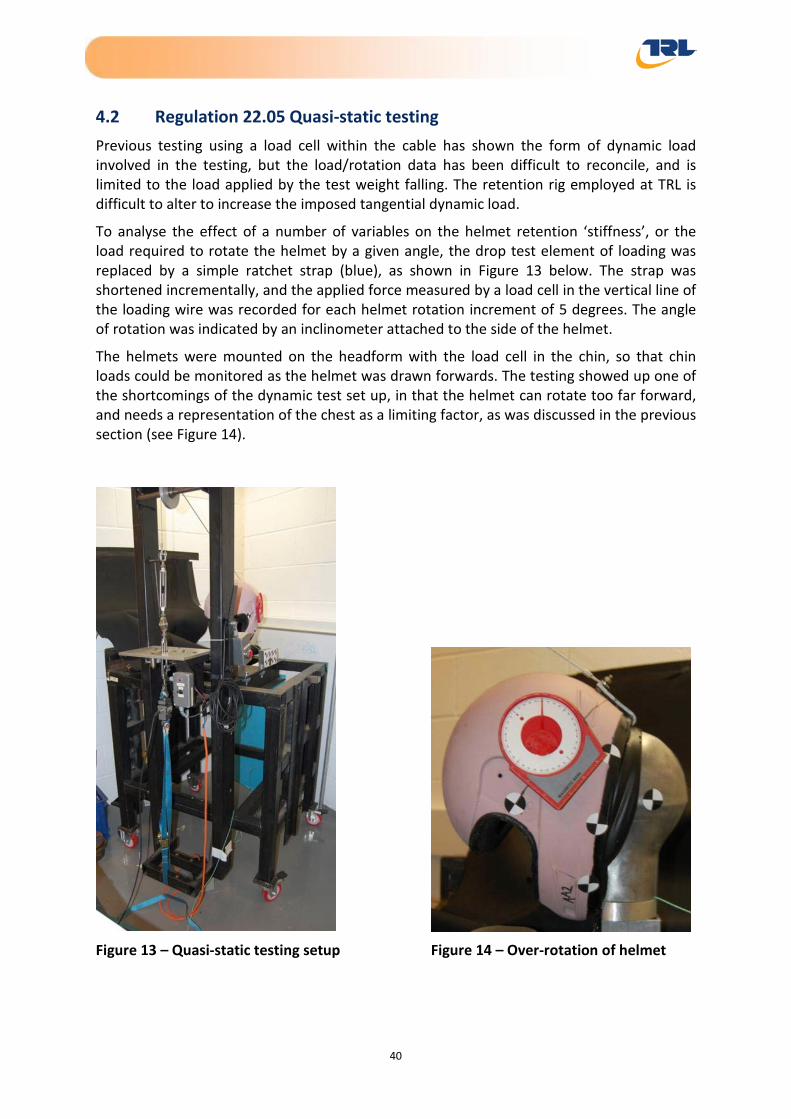
Helmet Retention Report
4.2 Regulation 22.05 Quasi-static testing Previous testing using a load cell within the cable has shown the form of dynamic load involved in the testing, but the load/rotation data has been difficult to reconcile, and is limited to the load applied by the test weight falling. The retention rig employed at TRL is difficult to alter to increase the imposed tangential dynamic load.
To analyse the effect of a number of variables on the helmet retention ‘stiffness’, or the load required to rotate the helmet by a given angle, the drop test element of loading was replaced by a simple ratchet strap (blue), as shown in Figure 13 below. The strap was shortened incrementally, and the applied force measured by a load cell in the vertical line of the loading wire was recorded for each helmet rotation increment of 5 degrees. The angle of rotation was indicated by an inclinometer attached to the side of the helmet.
The helmets were mounted on the headform with the load cell in the chin, so that chin loads could be monitored as the helmet was drawn forwards. The testing showed up one of the shortcomings of the dynamic test set up, in that the helmet can rotate too far forward, and needs a representation of the chest as a limiting factor, as was discussed in the previous section (see Figure 14).
Figure 13 – Quasi-static testing setup Figure 14 – Over-rotation of helmet
40

Helmet Retention Report
This form of testing has provided a short cut to the dynamic approach (using a high speed camera) to identify those factors which may have a strong bearing on retention.
The experiments concentrated on the two different makes of full face helmet, and the results have shown them to possess noticeably different retention capacities on the test headforms used. Figure 14 above shows the form of extreme helmet retention that can be achieved with the chin strap secured, but with no chest representation.
The first area of study was the most obvious, namely the tightness of retention on one helmet style. Tests were carried out with the neck strap done up as tight as possible, then with the strap slightly loose, and then with the strap undone.
The results are charted in the graph below (Figure 15), which shows that the load on the chin plays a very large part in the force in the cable required to rotate off the head, and the angle through which the helmet has to rotate before becoming loose. There appears to be an almost fourfold difference in tangential force between the strap being attached and not being done up, showing the very strong resistive force that the chinstrap provides. This may be explained by the ‘locking-in’ of the helmet chinguard into the headform jaw and base area. As the helmet tries to move up over the crown over the headform the force acting upwards, through the chin, increases.
Figure 15 – Example of loading
The helmet is shown to rotate by about 25 to 30° with very little applied force (the orange line), and the imposed force then drops rapidly, showing that the helmet is coming off the head. But the chin load (the blue line) continues to rise as the chinbar engages on the load cell on the chin, clearly a false condition.
0
50
100
150
200
250
300
350
400
450
0° 5° 10°15°20°25°30°35°40°45°50°
AA2 Tight BareChin (N)
AA2 Tight BareCable (N)
41

Helmet Retention Report
There is a degree of non-uniformity in the data presented, as the values of cable load are not static as the loading increases, because of the slippage of the helmet around the test headform. This non-uniformity could be reduced if the loading method was mechanised to produce a smoother load/time application, with automatic recording of the force and angle. It was observed that one set of tests conducted with the strap tight returned a performance that is almost identical to that shown with the strap loose. This appears to verify the suggestion that the loading is direct from the locked-in chinguard.
Accordingly the absolute values of the cable force, and the absolute shape of the graphs depicted in Figure 16 below, are likely to be indicative of the factors being investigated, rather than absolute representations.
This particular set of data shows that the cable force measured when there are different chin strap tightness can be differentiated, but not with the same form of clarity that was displayed in the data derived from the angular change in the high speed film.
The tight chin strap couples the helmet to the head earlier, preventing about 10° of low load rotation. The chin strap with two fingers looseness, defined by the ability to position two fingers between the strap and the chin, appears to halve the force required to pull the helmet from the head. This is an important finding in view of the way in which helmets are worn on the road.
The unstrapped helmet falls off earlier and under an even further reduced external loading.
This form of testing allows an insight into the factors affecting rolloff, but cannot be viewed as an alternative to the dynamic tests, either to ECE Reg 22 or other defined types, because of the slow loading rate.
Figure 16 – Cable force for AA size 58 helmet with varied chin strap tension
0
50
100
150
200
250
300
350
400
450
Tight
Tight
Tight
2 fingers
2 fingers
2 fingers
Undone
42

Helmet Retention Report
The same form of testing was carried out with the other helmet make, and it was obvious that this was a much closer fit onto the test headform used in these tests. Whilst the ultimate force required to remove the helmet from the headform was slightly higher than for the other helmet model, the lack of chin strap use had a very similar effect, with the helmet coming off the headform with a lower load and smaller degree of rotation (see Figure 17).
Figure 17 - Cable force for BB size 58 helmet with varied chin strap tension
Repeatability of testing is a very serious concern in this form of testing, and a pair of helmets was subject to a number of repeated tests, as illustrated in Figure 18 below. It was clear that the ability of the helmet to resist this form of test can diminish with repeated testing, even though previous testing did not highlight this as an issue.
Figure 18 – Repeated testing of 2 BB helmets
0
100
200
300
400
500
600
Undone
Tight
0
200
400
600
800
1000
1200
1400
1600
1800
2000
Angl
e 0° 5° 10°
15°
20°
25°
30°
35°
40°
45°
50°
55°
60°
65°
BB6 Tight
BB6 Tight
BB6 Tight
BB5 Tight
BB5 Tight
BB5 Tight
43

Helmet Retention Report
The test results show that as the helmet was pulled repeatedly from the head the plastic at the rear of the helmet stretched permanently, so that the resistive force fell from a peak of about 1800 N to about 400 N, a very significant change. The angular range of resistance also diminished.
Photographs taken during this form of testing show that at extreme angles of rotation, it is the plastic band at the nape of the neck band that locks onto the rear of the crown of the head (see Figure 19), as a consequence of the chin bar being able to hook beneath the test headform’s chin. This is clearly an important element of helmet fit that may not be immediately obvious to a potential purchaser or user.
Figure 19 – Showing plastic band ‘locking’ onto rear of headform
Further tests were carried out using a short wig on the headform for both helmet types, but this made a small difference to the resistive force. It appears that it actually increased the resistive force, but appeared to allow the helmet to rotate forwards to a greater extent before that force was exerted – see Figure 20.
44

Helmet Retention Report
Figure 20 – Variations when using a wig
A soft chin piece was replicated using a small piece of comfort foam taped to the chin piece, with the data shown in Figure 21. The influence of the short wig and the soft chin piece tended to increase the rotational range of the helmet and reduce the load in the loading cable required to roll off. The addition of these elements into the testing proved to make the results less replicable, although trends were visible.
Figure 21 – Effect of a wig and foam chin on the BB helmet type
0
100
200
300
400
500
600
700
800
900
1000
Angl
e 0° 5° 10°
15°
20°
25°
30°
35°
40°
45°
50°
55°
60°
65°
BB5 Tight Bare
BB5 Tight Bare
BB5 Tight Short wig
BB5 Tight Short wig
0
100
200
300
400
500
600
700
800
Angl
e 0° 5° 10°
15°
20°
25°
30°
35°
40°
45°
50°
55°
60°
65°
BB5 Tight Bare
BB5 Tight Bare
BB5 Tight, foam Shortwig
BB5 Tight, foam Shortwig
45

Helmet Retention Report
Intriguingly, conducting the same tests with the other helmet type showed that the addition of the foam chin and the short wig made almost no difference to the retention of the helmet other than the extent to which the helmet was able to rotate before there was any significant force developed (see Figure 22). The slope of the loading line is almost identical in all 3 cases, suggesting that it is the nape structure that is performing the majority of the roll off resistance but the reaction of the chinguard with the jaw will also significantly affect this.
The level of force is much lower than for the other helmet type, showing that the resistance to rolloff is dependent more on the match of the helmet to the headform (and by extension to the profile and fit to an individual user’s head) than these other factors.
Figure 22 – Effect of a wig and foam chin on the AA helmet type
The chin sections were then cut off two of the size 58 helmets for testing to determine the extent that the chinbar was responsible for helmet retention. The modified helmets are shown in Figure 23 below. The internal foam cheek pieces were retained in both helmets so that the alignment of the chinstraps remained unaltered.
0
50
100
150
200
250
300
350
Angl
e 0° 5° 10°
15°
20°
25°
30°
35°
40°
45°
50°
55°
60°
65°
AA3 (58 Tight, foamShort wig
AA3 (58) Tight, foamShort wig
AA3(58) Tight Bare
46

Helmet Retention Report
Figure 23 – Two helmets with chin sections removed
The helmets were then put on a size 57 headform to allow additional photographs to be taken, and it was found that both helmets could be rotated forwards by hand – so as to come off the headform – with very little physical force (see Figure 24).
Figure 24 – Helmets with chin section removed rotated on headform
47

Helmet Retention Report
This is clearly an extreme form of test, in that these helmets models were not intended to act as 3/4 style models. However it shows that the presence of the chinbar is a very real factor in the retention, something that the statistical data has shown in terms of the retention of different styles of helmet.
4.3 Inertial loading tests To investigate the potential for helmet loss from inertial loading, a series of tests have been completed using an instrumented test headform attached to a dynamic sled (known internally as the Low Energy Sled, LES). The basic configuration of a test helmet on a headform attached to the load bed of the sled is illustrated in Figure 25.
Figure 25 – Sled configuration at 0°
The configuration of the test is such that it simulates the loading on the helmet that may occur during an impact event resulting in the body being abruptly restrained, or an impact to the helmet that creates a relative motion of the helmet on the head due to the inertia gained by the helmet. This differs considerably to the methods prescribed in the standards, where the loads applied are in the same place throughout the test and the helmet is not entirely free. In all cases the head was attached rigidly to the base of the sled, so that the loads delivered were purely linear.
The ~80kg sled was accelerated along its track by stretched elastic cords and brought to rest abruptly from speeds of up to 7.5 m/s by the use of tuned foam blocks. The motion of the helmet fitted to the headform and loading on the instrumented chin part were monitored to see if patterns exist for simulated helmet loss events. The test pulse was varied somewhat arbitrarily by the adoption of different foam block thicknesses and stiffnesses, but ranged from peak acceleration levels of 17.3 g to 175.8 g. The severity of the pulse aims to vary the relative motion of the helmet and head with a more severe pulse providing the greatest speed differential between the head and helmet.
48

Helmet Retention Report
Various other parameters were adjusted to simulate potential helmet loss events. The headform was orientated at two angles, 55° to horizontal (see Figure 26) and 0° to horizontal (as shown in Figure 25) with the sled being decelerated in the horizontal plane through the centre transverse plane of the headform. The chin strap tightness was adjusted and both deformable and rigid instrumented chin section were used. Wigs were also used in some tests.
Figure 26 – Sled configuration at 55°
In total 18 tests were completed using two helmet models, the first in three size variants and the second in two variants. In four tests, the headform was modified and the rigid chin section replaced with a soft foam pad.
A matrix of the test configuration is shown in Table 3.
4.3.1 Observations
Slippage and rotation was observed in all tests, with varying degrees, depending on the test configuration. The direction of rotation of the helmet was influenced by the headform orientation. With the headform orientation set to 0° the helmet tended to rebound onto the headform and then nod downwards (chin towards sternum) rather than rotate backwards (chin towards brow) for the 55° orientation headform. This is illustrated in Table 4.
Helmet ejection was only possible when the chinstrap was undone. Test #109, #110 and #111 illustrate that ejection was possible for the first helmet type with both a 55° and 0° headform orientation. Equivalent tests with the same helmet but with the chinstrap either loosely (#112), or tightly connected (#108) did not allow ejection for similar test conditions.
Similarly, the second helmet type was only ejected in test #117 where the chinstrap was undone. Equivalent tests with the chinstrap either loose (#116) or tight (#118) resulted in the helmet being fully restrained on the head. Furthermore, the addition of a deformable chin section and wig did not result in this helmet being ejected (#119).
49
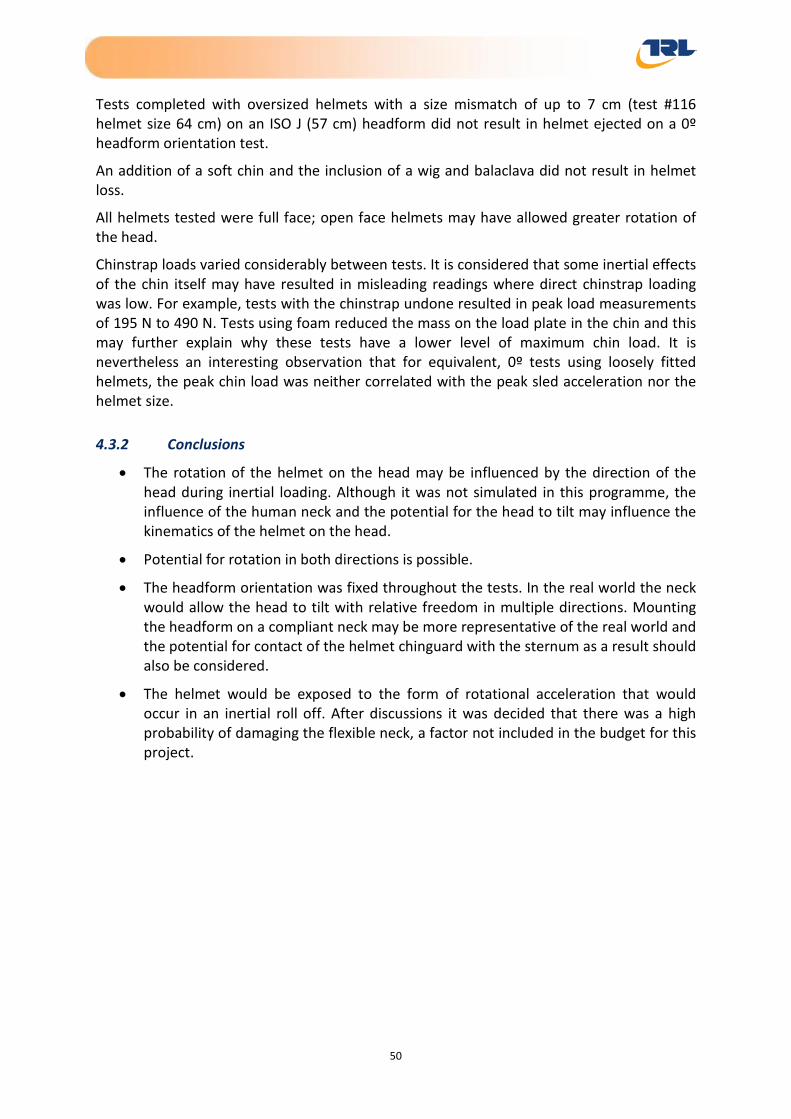
Helmet Retention Report
Tests completed with oversized helmets with a size mismatch of up to 7 cm (test #116 helmet size 64 cm) on an ISO J (57 cm) headform did not result in helmet ejected on a 0º headform orientation test.
An addition of a soft chin and the inclusion of a wig and balaclava did not result in helmet loss.
All helmets tested were full face; open face helmets may have allowed greater rotation of the head.
Chinstrap loads varied considerably between tests. It is considered that some inertial effects of the chin itself may have resulted in misleading readings where direct chinstrap loading was low. For example, tests with the chinstrap undone resulted in peak load measurements of 195 N to 490 N. Tests using foam reduced the mass on the load plate in the chin and this may further explain why these tests have a lower level of maximum chin load. It is nevertheless an interesting observation that for equivalent, 0º tests using loosely fitted helmets, the peak chin load was neither correlated with the peak sled acceleration nor the helmet size.
4.3.2 Conclusions
• The rotation of the helmet on the head may be influenced by the direction of the head during inertial loading. Although it was not simulated in this programme, the influence of the human neck and the potential for the head to tilt may influence the kinematics of the helmet on the head.
• Potential for rotation in both directions is possible.
• The headform orientation was fixed throughout the tests. In the real world the neck would allow the head to tilt with relative freedom in multiple directions. Mounting the headform on a compliant neck may be more representative of the real world and the potential for contact of the helmet chinguard with the sternum as a result should also be considered.
• The helmet would be exposed to the form of rotational acceleration that would occur in an inertial roll off. After discussions it was decided that there was a high probability of damaging the flexible neck, a factor not included in the budget for this project.
50

Helmet Retention Report
Table 3 – Low Energy Sled test configuration matrix
Test reference
Speed (m/s)
Helmet ref
Helmet size (cm)
Chinstrap fastening Headform configuration
Peak acceleration
(g)
Stopping distance
(mm)
Chin load (N) Outcome
105 3.62 AA3 58 Tight 55° 17.3 68.7 88.5 Helmet retained 106 3.63 AA3 58 Tight 55° 17.1 68.5 85.6 Helmet retained 107 3.63 AA3 58 Tight 55° 17.4 65.5 239.9 Helmet retained 108 3.62 AA3 58 Tight 55° 17.2 55.2 280.8 Helmet retained
109 3.62 AA3 58 Not fastened 55° 21.4 55.6 195.4 Loosely restrained, chinguard over chin
110 6.94 AA3 58 Not fastened 55° 27.4 153.4 248.6 Loosely restrained, chinguard over nose
111 5.68 AA3 58 Not fastened 0° 27.9 124.1 229.7 Ejected 112 5.74 AA3 58 Loose 0° 23.9 125.1 749.1 Retained 113 5.63 AA3 58 Loose 0° 23.4 133.8 1536.0 Retained 114 5.75 AA3 58 Loose 0° 23.7 124.7 929.0 Retained 115 5.74 AA6 60 Loose 0° 124.2 140.9 1472.8 Retained 116 5.76 AA8 64 Loose 0° 146.9 126.6 861.0 Retained 117 5.75 BB6 58 Not fastened 0° 155.8 125.5 253.3 Ejected 118 5.78 BB6 58 Tight 0° 120.3 125.5 899.8 Retained
119 5.80 BB6 58 Adjusted to foam but not compressing
0°, 25 mm foam chin pad 141.5 124.3 844.1 Retained
120 5.80 BB6 58 Adjusted to foam but not compressing
0°, 25 mm foam chin pad 175.8 128.1 821.5 Retained
121 5.81 BB10 62 Adjusted to foam but not compressing
0°, 25 mm foam chin pad 166.2 126.9 811.4 Retained
122 5.36 BB10 62 Adjusted to foam but not compressing
55°, 25 mm foam chin pad 119.8 126.1 155.1 Retained
51

Helmet Retention Report
Table 4 – Typical responses for fastened helmets
Deceleration phase >>>>>>>>>> Rebound phase
55° configuration with chinstrap fastened
Forward motion of helmet on
headform, some slight movement upwards
Rebound motion of helmet back onto the headform, more
significant movement upwards
Followed by rotation of chinguard upwards towards brow of helmet
0° configuration with chinstrap fastened
Forward motion of helmet on headform
Rebound of helmet on headform, timing roughly coincident with
head rebound phase
Rotation of helmet forward on headform
52

Helmet Retention Report
4.4 Snell stability test The Reg 22.05 test procedure limits the drop height available to 0.5 m, and thus a simple drop test, similar to that used in the Snell test regime, was employed. A wall mounted headform was attached to one of the structural members in the building in Bay 2 within TRL and the helmets were mounted, face down, on the size 57 headform.
Two masses, of 4 kg and 10 kg, were used, and dropped over distances of 0.5 m and 1.0 m. The test rig is illustrated in Figure 27 below, with the 10 kg mass on the 1 m slide, without any instrumentation. The load was attached to the rear of the helmet through a hook via a webbing strap to the top of the drop shaft.
Figure 27 – Stability test rig
During the testing the movement of the helmet was analysed using high speed film as before, from which helmet rotation was derived, and the forces on the drop cable and on the chin were measured. Two helmets of different make but of the correct size (AA1 and BB6) were tested as full face units, and then their chin pieces were sawn off to determine the influence of the chin bars on the retention mechanism.
Two further helmets (AA3 and BB5) were tested to view the influence of helmet size. Finally a half helmet (CC2) of the correct size, conforming to the DOT FMVSS standard, was tested to see how this form of helmet compared to those conventionally used in the UK.
The simple test matrix (see Table 5) shows in which instances the helmet rotated off the headform, and the peak value of chin force observed.
53

Helmet Retention Report
Table 5 – Stability test configuration matrix
Test configuration
4 kg @ 0.5 m 4 kg @ 1 m 10 kg @ 0.5 m 10 kg @ 1 m
Helmet Load (kN) Outcome Load
(kN) Outcome Load (kN) Outcome Load
(kN) Outcome
AA1 0.4 Retained 0.4 Ejected 0.6 Ejected 0.45 Ejected
AA1 cut 0.55 Retained 0.55 Ejected 0.35 Ejected 0.45 Ejected
BB6 0.5 Retained 0.85 Retained 0.75 Ejected 0.75 Ejected
BB6 cut 0.4 Retained 0.55 Ejected 0.50 Ejected 0.50 Ejected
AA3 0.15 Retained 0.30 Retained 0.50 Ejected 0.60 Retained
BB5 0.55 Retained 0.65 Retained - 1.0-1.5 Retained
CC2 0.55 Retained 0.60 Retained 0.45 Ejected 0.45 Ejected
The helmet rotation angle data derived from the high speed film analysis for a number of variables is presented below.
An initial analysis of data reproduction of helmet rotation was carried out to ensure that this was a method that would show real differences between helmets and different test conditions. Two tests (Ret25 and Ret25a) using identical helmets and loadings showed remarkably similar results, as illustrated in Figure 28 below, providing a sense of security in the outcomes.
Figure 28 – Showing two separate tests using identical helmets and loadings
0
50
100
150
200
250
300
350
400
1 3 5 7 9 11 13 15 17 19 21 23 25 27 29 31 33 35 37
25 corrected
25a corrected
54
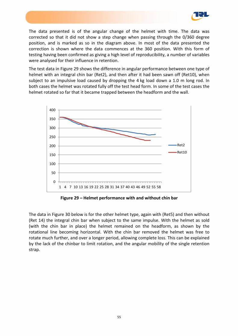
Helmet Retention Report
The data presented is of the angular change of the helmet with time. The data was corrected so that it did not show a step change when passing through the 0/360 degree position, and is marked as so in the diagram above. In most of the data presented the correction is shown where the data commences at the 360 position. With this form of testing having been confirmed as giving a high level of reproducibility, a number of variables were analysed for their influence in retention.
The test data in Figure 29 shows the difference in angular performance between one type of helmet with an integral chin bar (Ret2), and then after it had been sawn off (Ret10), when subject to an impulsive load caused by dropping the 4 kg load down a 1.0 m long rod. In both cases the helmet was rotated fully off the test head form. In some of the test cases the helmet rotated so far that it became trapped between the headform and the wall.
Figure 29 – Helmet performance with and without chin bar
The data in Figure 30 below is for the other helmet type, again with (Ret5) and then without (Ret 14) the integral chin bar when subject to the same impulse. With the helmet as sold (with the chin bar in place) the helmet remained on the headform, as shown by the rotational line becoming horizontal. With the chin bar removed the helmet was free to rotate much further, and over a longer period, allowing complete loss. This can be explained by the lack of the chinbar to limit rotation, and the angular mobility of the single retention strap.
0
50
100
150
200
250
300
350
400
1 4 7 10 13 16 19 22 25 28 31 34 37 40 43 46 49 52 55 58
Ret2
Ret10
55

Helmet Retention Report
Figure 30 – Helmet performance with and without chin bar
Three DOT approved half helmets were purchased, but only the medium sized unit was tested. The helmet remained on the headform in both the drop tests using the 4 kg mass – shown in Figure 31 as Ret33, with 0.5 m drop, and as Ret34, the 1.0 m drop. The helmet was pulled off the headform in both the 10 kg tests (Ret35 and 36).
Figure 31 – Performance of DOT approved half helmets
The difference in performance can be seen in the slopes of the data lines. In the lower mass tests (the red & blue data lines) the rotation of the helmet is resisted as the slope becomes horizontal over a relatively short time period.
0
50
100
150
200
250
300
350
400
1 4 7 10 13 16 19 22 25 28 31 34 37 40 43 46 49 52 55 58
Ret5
ret14
0
50
100
150
200
250
300
350
400
1 4 7 10 13 16 19 22 25 28 31 34 37 40 43 46 49 52 55 58
ret33
ret34
35 corrected
36 corrected
56

Helmet Retention Report
In the heavier mass tests (green & purple data lines) the slope continues for longer and does not flatten since the helmet is free to rotate completely off the headform to drop to the floor. This helmet is secured to the head with a Y-shaped yoke on both sides (see Figure 32), and is thus more likely to resist rotation as a consequence, even without the chin piece. This additional rearwards aligned retention strap acts in the manner of the AROS device described previously.
Figure 32 – Half helmet on headform
It is not possible to test any helmet without the chin strap secured in these inverted helmet tests as the helmets fall off the headform even without any applied load.
The cable forces measured to cause these rotations are shown in Figure 33 below. As expected the forces measured increase in magnitude from Ret33 (0.4 kg at 0.5 m) to Ret36 (10 kg at 1.0 m). As the impulsive blow is delivered against an object (the helmet) that is free to respond to the impulse, the form of the load delivered is conditioned by that response. This can be seen most graphically in Ret35, where an initial response in rotation causes a delay in the delivery of the peak load. This form of load change or pulse is not visible in the time history of the helmet rotation.
57

Helmet Retention Report
Figure 33 – Variation in cable force with time
The data is presented in kN acting vertically downwards, and the values shown can be seen to be significantly larger than were produced for the quasi-static testing. Thus whilst the quasi-static testing can act as an aid to establishing general trends in retention, at present only this form of dynamic testing is assured to generate a time history of force likely to exist in real world collisions.
5 User survey data TRL hosted an online user survey, encouraging a wide range of motorcycle helmet users to share their experience and provide comments relating to helmet fit. In total, there were 459 replies across a wide range of user age and riding experience.
The user survey asked riders about their age, experience and general motorcycle use information relating to helmet use and choice. A selection of that user data is shown in below, commencing (Figure 34) with the range of head size, as defined by the circumference of the marked helmet.
-2.5
-2
-1.5
-1
-0.5
0
0.5
1 5 9 13 17 21 25 29 33 37 41 45 49 53 57 61 65 69 73 77
ret 33
ret 34
ret35
ret36
58

Helmet Retention Report
Figure 34 – Range of head sizes
This was then compared to declared head size, which showed that about 25% of all users wore a helmet that did not match their head size, as shown in Figure 35 below.
Figure 35 – Comparison of head size & helmet size
This data was interrogated further to show the range of the mis-matches, illustrated in Figure 36 below.
0
20
40
60
80
100
120
140
160
180
200
X-Small(53-54)
Small (55-56)
Meduim(57-58)
Large (59-60)
X-Large(61-62)
Don't Know Other
Size of Helmets
0
50
100
150
200
250
300
350
Matched Not matched Unknown
Head Size & Helmet Size
Matched
Not matched
Unknown
59

Helmet Retention Report
Figure 36 – Range of mis-matches
Whilst the majority of the mismatches were by one size only, there were some extreme self-reported mismatches.
Helmet matching is something that may require expert guidance from a trained helmet salesperson, something that may not be available when buying remotely, or from a discount seller.
The responses to the source of helmets (Table 6) showed that whilst a majority of buyers purchase directly, a large number of buyers bought remotely, producing a real potential for mismatch. What is most surprising is that only two respondents reported trying on a helmet in a shop first before a remote purchase.
Where purchased? Number
Bought from Rental Company after use 1
Direct from Manufacturer 2
Exhibition/Trade Show 12
Gift 8
Government provided 1
Tried in shop & bought from internet 2
Internet auction (eBay/ADMAG) 12
Internet shop 89
Friend 1
Shop 331
Table 6 – Source of helmets
0
10
20
30
40
50
60
1 sizebigger
2 sizesbigger
3 sizesbigger
4 sizesbigger
1 sizesmaller
2 sizessmaller
4 sizessmaller
Helmet Size Difference to Head Size
1 size bigger
2 sizes bigger
3 sizes bigger
4 sizes bigger
1 size smaller
2 sizes smaller
4 sizes smaller
60

Helmet Retention Report
Whilst most postal sellers state that they are willing to accept returns, and that they do not sell these returns on, there has to be a question about where these unsuitable helmets end up.
The responses to the influence of various factors on the purchase of a helmet (Figure 37) were reassuring; showing that fit was the major influence. But even so, 3 respondents to question 19 (How important was fit) responded not at all, whilst a further 9 said not very important.
Figure 37 – Factors influencing helmet purchase
The chin strap tightness question (produced the following responses (Table 7).
Tightness Number
Loose (space for 3-4 fingers) 2
Slightly loose (space for 2 fingers) 289
Tight as possible 168
Table 7 – Chin strap tightness
As the experimental test data in this report suggest that chin strap tightness is a significantly important element in retention (to the extent that it may halve the force required to allow roll off), there appears to be a large proportion of helmet users who are unwittingly compromising this aspect of helmet performance. One user was able to remove the helmet without undoing the strap.
050
100150200250300350400
Influence Factors
61
Helmet Retention Report
6 Conclusions Motor cycle helmets are acknowledged to provide a form of head protection that is useful at both individual and societal levels.
That form of protection is lost when a helmet separates from a user’s head. In the past helmet loss has been attributable to helmet failure, misuse and roll off, but the majority of helmet testing standards include tests to limit roll off from a test head form.
A study of statistical data suggests that helmet loss occurs in about 5% of reported collisions involving injury, and this represents a population of users without head protection.
The current form of statutory roll off testing involves the helmet being drawn forwards on an arc that causes the helmet chin bar to hook beneath the user’s chin in a manner that would not be possible in a collision, and is therefore not representative of real world collisions.
Equally the tests include the retention straps being tightened below the test headform to a level of tightness that a user survey has suggested is inappropriate to real world conditions. A more representative level of tightness allows roll off at lower loads.
The level of inertial force on a helmet throughout a collision phase is not known with any degree of accuracy. Values of between 20 g and 40 g have been suggested, and this is something that mathematical modelling may assist to verify. The roll off testing produces values of tangential force of this order, depending on the fit of the head to the headform.
Many users are wearing helmets that are reportedly the wrong size for their heads – this may be because an increasing number of sales are through the internet, preventing knowledgeable sales staff from assessing fit and suitability. The use of a helmet that is not the correct size or shape will increase the potential for loss.
The ability to remove the helmet whilst done up was <1% in our survey, which cannot fully account for the 5% loss reported in the real world. This loss could not easily be demonstrated in standard tests even with the chinstrap undone.
Open-face helmets were not tested for this project, but it was shown that the removal of the chin bar from a full face helmet significantly lowered the force required for the helmet to roll off the headform.
The mechanisms for helmet loss are still not fully understood. The involvement of the sternum and rotation of the neck are believed to be significant factors, which could be tested in the future.
Sled testing using a headform attached rigidly to the sled base did not cause helmet loss. Rotation of the head as an inertial mechanism (without helmet contact) must be included in any further sled testing. This requires the use of a robust and representative flexible neck.
62

Helmet Retention Report
7 Bibliography Bourdet, N. e. (2010). Behaviour of Helmets during head impact in real accident cases of
motorcyclists. International Journal of Crashworthiness, 17:1, 51-61.
Carnicky, J. &. (2006). Three-dimensional Measurement of Human Face with Structured Light Illumination. Measurement Science Review, 6.
COST 327. (2000). Motorcycle Safety Helmets, Final Report.
COST 327. (2001). Interim Report. Accident Description and Analysis of Motorcycle Safety Helmets.
Crandon, I. e. (2009). The impact of motorcycle head trauma at a tertiary hospital in Jamaica. BMC Research Notes 2009(2:172).
Deguchi, M. (2003). Modeling of a Motorcycle for Collision Simulation. 18th ESV Conference, (p. Paper no. 157).
Deguchi, M. (2005). Simulation of a Motorcycle-Car Collision. 19th ESV Conference, (pp. Paper no. 05-0041).
Deyerl, E. &. (2008). Computer Simulation of Staged Motorcycle-Vehicle Collisions using EDSMAC4. SAE Congress.
Fernandes, F. (2013). Finite Element Analysis of Helmeted Impacts and Head Injury Evaluation with a Commercial Road Helmet. IRCOBI Conference 2013, (pp. 431-442).
Gilchrist, A. &. (1992). Critical Assessment of Helmet Retention Test Methods. IRCOBI, (pp. 25-36).
Gilchrist, A. M. (1998). Survey of head, helmet and headform sizes related to motorcycle design. Ergonomics, 31(10), 1395-1412.
Haiyan, L. e. (2007). Investigation of the Critical Geometric Characteristics of Living Human Skulls using Medical Image Analysis Techniques. Journal of Vehicle Safety, 2(4), 345-367.
Halldin, P. &. (2013). The Development of Next Generation Test Standards for Helmets. Proceedings of the 1st International Conference on Helmet Performance and Design, (pp. 1-1 - 1-8). London.
Huang, B. &. (2004). A Literature Review of Motorcycle Collisions, Final Report. Oxford University Transport Studies Unit, Oxford.
Hurt, H. T. (1997). Feasibility Study of Upgrading FMVSS, Motorcycle Helmets. Final Report for NHTSA.
63

Helmet Retention Report
Hurt, H. T. (1998). Testing the Positional Stability of Motorcycle Helmets. ESV 1998.
ITARDA Information. (2002). Information No.39: Motorcycle Accidents and Helmets.
ITARDA Information. (2006). Information No. 61: Is Your Helmet Securely Fastened?
Kasantikul, V. (2001). Motorcycle Accident Causation and Identification of Countermeasures in Thailand Vol 1: Bangkok Study. Final Report, Chulalongkorn University.
Koyasu, T. A. (2007). 3D head model generation using full-face head shape measurement system. Syst.Comp., 38, 82-91.
Larder, D. (1984). Analysis of Serious Two wheeled Motor Vehicle Accidents. University of Birmingham, Accident Research Unit, Birmingham.
Loftis, K. e. (2011). Using Computed Tomography Scans for Analyses of Motorcycle Helmets in Real World Crashes. Biomedical Science Instrumentation, 47, 234-239.
MAIDS. (2004-2008). In-Depth Investigation of Accidents Involving Powered Two Wheelers. ACEM.
Mellor, A. S. (2007). Motorcyclists' Helmets and Visors - Test Methods and New Technologies. Crowthorne: TRL.
Mills, N. &. (1985). The Biomechanics of Motorcycle Helmet Retention. IRCOBI Conference, (pp. 117-127).
Mills, N. (1996). Accident Investigation of Motorcycle Helmets. Impact: Journal of the Institute of Traffic Accident Investigators, Autumn, 46-51.
Nakamura, N. (1973). Motorcycle Accident and Helmet. The Japanese Council of Traffic Science.
NHTSA. (2004, March). Motorcycle Helmet Effectiveness Revisited. NHTSA National Center for Statistics and Information.
Nieboer, J. e. (1993). Motorcycle Crash Test Modelling. SAE.
Otte, D. (1997). Benefit of in depth modelling for analysing injury mechanisms of accidents with bicyclists and motorcyclists. Proceedings of International Symposium on Real World Crash Injury Research (pp. 3.1-1 - 3.1-13). CCIS Consortium.
Otte, D. (2006). Technical parameters for determination of impact speed for motorcycle accidents and the importance of relative speed. SAE.
Ouellet, J. &. (2006). Motorcycle Helmet Effect on a per-crash basis in the Thailand and Hurt Studies. Traffic Injury Prevention(7), 1-6.
64

Helmet Retention Report
Philip, A. F. (2013). Helmets Prevent Motorcycle Injuries with Significant Economic Benefits. Traffic Injury Prevention(14:5), 496-500.
Smith, L. K. (n.d.). Analysis of Police Collision Files for Motorcycle fatalities in LONDON, 2006-2009. Crowthorne: TRL.
Thai, K. P. (2009). Comparison of Helmet Stability on Helmets and Headforms and Human Subjects. 2009 Australasian Road Safety Research, Policing and Education Conference, November 2009, (pp. 557-563). NSW.
Thai, K. P. (2009). Helmet Stability and Fit in Australian Pedal and Motorcyclist Populations. 17th World Congress on Ergonomics. Beijing.
Unknown. (2008). Virtual Modelling of Safety Helmets: Practical Problems. International Journal of Crashworthiness, 13:4, 451-467.
WHO. (n.d.). Why are helmets needed? Helmets: A Road Safety Manual.
Zellmer, H. (1993). Investigation of the Performance of Motorcycle Helmets Under Impact Conditions.
65

Helmet Retention Report
Appendix A Summary of Helmet Standard requirements Summary tables highlighting the key requirements of each helmet standard for whole system, chinstrap and release mechanism.
66

Helmet Retention Report
Standard Restraint system strength Limit Helmet stability Limit Comments
ECE Regulation 22.05
Dynamic loading Helmet on headform Supported by shell crown Preload 15 kg Drop mass 10 kg Drop height 0.75 m
35 mm dynamic 25 mm residual
Forward roll-off Headform vertical Headform size is ‘least favourable’ in size range Preload 3 kg Drop mass 10 kg Drop height 0.5 m
30° rotation
BS 6658: 1985
Dynamic loading Helmet on headform and base Supported by shell rim and headform Preload 7 kg Drop mass 10 kg Drop height 750 mm
1st test 32 mm dynamic 16 mm residual 2nd test 25 mm dynamic 8 mm residual
Forward pull off Headform* inclined at 45° Headform size G (560 mm) for size K (580 mm) helmet Preload 0 kg Drop mass 4 kg Drop height 1.0 m (3 off)
Retain helmet
*Headform fitted with wig and foam neck section.
JIS T 8133 Dynamic loading Helmet on headform and base Supported by shell rim and headform Preload 15 kg Drop mass 10 kg Drop height 240 mm (Type 1) 750 mm (Type 2)
Type 1 35 mm dynamic 25 mm residual Type 2 35 mm dynamic 25 mm residual
Forward roll-off Headform vertical Headform size is ‘least favourable’ in size range Preload 3 kg Drop mass 10 kg Drop height 0.175 m (Type 1) 0.500 m (Type 2)
Retain helmet
FMVSS 218 Static loading Helmet on headform and base Supported by shell rim and headform Preload 22.7 kg (30 s) Test mass 113.4 kg (120 s)
25 mm None N/A
Snell M2010
Dynamic loading Helmet on headform and base Supported by shell rim and headform Preload 23 kg (60 s, removed before dynamic) Drop mass 38 kg Drop height 120 mm
30 mm dynamic Forward and rearward pull off Headform inclined at 45° Headform size smallest for helmet size range Preload <1 kg Drop mass 4 kg Drop height 0.6 m (3 off)
Retain helmet
67

Helmet Retention Report
Standard Slippage Limit Abrasion Limit Webbing width Limit
ECE Regulation 22.05
Snatch load cycling Pre-load 20 N Stroke 50 mm (25 mm lift) Frequency 0.5-2 Hz 520 cycles
10 mm slip Loaded cycling plus strength test Load 20 N Stroke 100 mm Frequency 0.5-2 Hz 5000 cycles 3 kN (100 mm/min) post cycling tensile test
No failure of webbing permitted in tensile test
Width measurement under load Static load 150 N
width ≥20 mm
BS6658: 1985
Snatch load cycling Pre-load 20 N Stroke 50 mm (25 mm lift) Frequency 0.5-2 Hz 520 cycles
10 mm slip Loaded cycling plus strength test Load 20 N Stroke 100 mm Frequency 0.5-2 Hz 5000 cycles 3 kN (100 mm/min) post cycling tensile test
No failure of webbing permitted in tensile test
Minimum 20 mm width prescribed N/A
JIS T8133 None N/A None N/A Width measurement under load Static load 150 N
width ≥20 mm
FMVSS 218 Quasi-static load Helmet on headform and base Supported by shell rim and headform Preload 22.7 kg (30 s) Load 113.4 kg (120 s) Rate (1-3 mm/s)
25 mm deflection
None N/A None N/A
Snell M2010
None N/A Degradation is considered through a recommendation that helmet life is 5 years only
N/A None N/A
68

Helmet Retention Report
Standard Inadvertent release Limit Ease of release Limit Durability of release
Limit Comments
ECE Regulation 22.05
Spherical probe test Probe diameter 100 mm Applied force 100 ±5 N
No release permitted
Quasi-static probe test Probe radius 2.5 ±0.1 mm Pre-load (tensile) 500 N (30 s) Test-load (tensile) 150 N
*Release force ≤30 N
**Cycling plus strength test Operation force 20 ±1 N Frequency >0.5 Hz 5000 cycles 2kN ±50 N (100 mm/min) post cycling tensile test
Shall not fracture or disengage
*Non-shell mounted release mechanism **Salt spray prior to test if includes metal parts
BS6658: 1985
Spherical probe test Probe diameter 40 mm Applied force 100 ±5 N
No release permitted
Quasi-static probe test Test-load (stirrup application) 500 ±10 N
Release force ≤15 N
Cycling plus strength test Operation force 22.5 ±2.5 N 2500 cycles 3 kN ±50 N (100 mm/min) post cycling tensile test
Shall not fracture or disengage
Quick release components shall be coloured red
Inertial load test 3 off drop Drop height 1.0 m Carrier 5 kg Impact base 200 kg
No release permitted
JIS T8133 Spherical probe test Probe diameter 100 ±3 mm
Shall not release
None N/A None N/A
FMVSS 218 None N/A None N/A None N/A Snell M2010
Not specified Inadvertent release shall not be possible
**Emergency helmet removability test Ability to remove helmet from headform in emergency situation using limited tools
Time to remove ≤30 s
None N/A **Not a specific test for usability of quick release part
69

Helmet Retention Report
Appendix B How helmets fit the head After the dynamic testing a number of the test helmets, plus a number of others purchased for other projects, were sectioned – from rear to rear – and placed on a size 57 headform to show the variation in the profile of the inner (shock absorbing) liner and comfort foam elements, as well as the sizing bands.
The photographs below show the variations in those profiles.
70

Helmet Retention Report
71

Helmet Retention Report
72


Helmet Retention Report
This study has two specific aims. The first is to see whether the existing test requirements in ECE Regulation 22.05 relating to dynamic helmet retention (the roll test) are realistically based, and how well existing helmet designs comply with these tests when new and used. The second is to identify the mechanism of helmet loss and to quantify the importance of relevant factors such as inertia effects, head geometry and flesh compliance and misuse.
TRL Crowthorne House, Nine Mile Ride, Wokingham, Berkshire, RG40 3GA, United Kingdom T: +44 (0) 1344 773131 F: +44 (0) 1344 770356 E: [email protected] W: www.trl.co.uk
PPR689
ISSN 0968-4093
ISBN 978-1-908855-97-8