Embed Size (px)
Citation preview
8/3/2019 PSRAO Welding Defects
http://slidepdf.com/reader/full/psrao-welding-defects 1/34
D N SHARMA – TRAINING OFFICERTraining Programme for CoE Instructors -
FOREMEN TRAINING INSTITUTE, DGE & T , Ministry of Labour, Govt. of India, Bangalore
HAND BOOK ON WELD DEFECTSWELD DEFECTS
FOREMEN TRAINING INSTITUTEBANGALORE

8/3/2019 PSRAO Welding Defects
http://slidepdf.com/reader/full/psrao-welding-defects 2/34
D N SHARMA – TRAINING OFFICERTraining Programme for CoE Instructors -
FOREMEN TRAINING INSTITUTE, DGE & T , Ministry of Labour, Govt. of India, Bangalore
Any process results in some deviations in the final product normally due to several variations in the
process parameters-minor or major. These deviations results in discontinuities in the final product /
service. When these discontinuities are not affecting the intended application / sections, then these
discontinuities are acceptable. If they are unacceptable, then these discontinuities are treated as
defects. These defects can be repaired; there by the product can be made fit to the intended job. Then
it is said that the part is salvaged. Sometimes if the defect is to severe the part can be rejected out
rightly.
Welding process is no exception. Hence discontinuities / defects do arise during welding. In this
booklet, various weld defects and their origin is described at length. As the presence of
imperfections in a welded joint may not render the component defective in the sense of being
unsuitable for the intended application, the preferred term is imperfection rather than defect. For thisreason, production quality for a component is defined in terms of a quality level in which the limits
for the imperfections are clearly defined, for example Level B, C or D in accordance with therequirements of BS EN ISO 5817. For the American standards ASME X1 and AWS D1.1, theacceptance levels are contained in the standards.
The application code will specify the quality levels which must be achieved for the various joints.
Imperfections can be broadly classified into those produced on fabrication of the component or
structure and those formed as result of adverse conditions during service. The principal types of imperfections are:
Fabrication:
• lack of fusion
• cracks
• porosity
• inclusions
• incorrect weld shape and size
Service:
• brittle fracture
• stress corrosion cracking
• fatigue failure
Welding procedure and welder technique will have a direct effect on fabrication imperfections.
Incorrect procedure or poor technique may produce imperfections leading to premature failure in
service.
FOREMEN TRAINING INSTITUTEBANGALORE
8/3/2019 PSRAO Welding Defects
http://slidepdf.com/reader/full/psrao-welding-defects 3/34
D N SHARMA – TRAINING OFFICERTraining Programme for CoE Instructors -
FOREMEN TRAINING INSTITUTE, DGE & T , Ministry of Labour, Govt. of India, Bangalore
Welding Codes are documents establishing legal obligations spelled out through laws and rules to
be complied with whenever engaging in the manufacture of certain constructions regulated by the
appointed Authority. In other words Welding-codes are laws covering minimum mandatory
requirements essential to guarantee public safety and reliability of large structures.
Some of the regulated items, object of law enforcement by means of Welding-codes, are grouped in
two types:
1. for pressure containment: Unfired Pressure Vessels, Power Boilers, Pipelines, etc.
2. for structures: Bridges, High Rise Structures, Ships, Lifts and lifting equipment etc.
Welding-codes describe the types of construction they are concerned with.
Welding Specifications cover requirements for voluntary adoption and no enforcement is meant
unless they are agreed upon between procuring agency and contractor as spelled out in a Purchase
Order. One could say that Welding-codes are essentially enforced Specifications.
Welding Standards cover industry agreed upon conventions like definitions of terms and of
symbols as used in the industry for conveying information.
Welding Recommended Practices reflect the recommendations of some of the most knowledgeable professionals in the field with the purpose of helping people improve the practical implementation of
different techniques and procedures and obtain best results.
One should always inquire which Authority is in charge of safety in the particular place, and which
are the latest binding Welding-codes applicable to the construction considered. The contractor
should understand Welding-codes as they represent legal obligations between the manufacturer and
the purchaser (or owner).
Welding-codes meeting is needed for Quality implementation.
When built into the product, Quality is not an expense it is a powerful asset contributing to the
economic success of any enterprise.
Can you assess the Quality of your welded Production?
FOREMEN TRAINING INSTITUTEBANGALORE

8/3/2019 PSRAO Welding Defects
http://slidepdf.com/reader/full/psrao-welding-defects 4/34
D N SHARMA – TRAINING OFFICERTraining Programme for CoE Instructors -
FOREMEN TRAINING INSTITUTE, DGE & T , Ministry of Labour, Govt. of India, Bangalore
Implementing Quality is NOT scrapping defective parts!
Of the three essential parameters for measuring the success of an industrial operation
• Price,
• On-time-Delivery and
• Quality
The last one is possibly the most important.
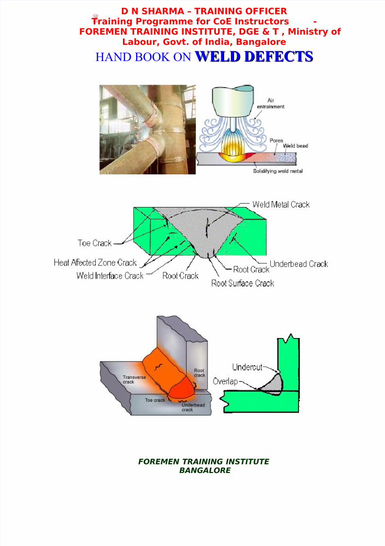
Welding Defects
1. Introduction
Common weld defects include:
i. Lack of fusion (LOF)
ii. Lack of penetration (LOP) or excess penetration
iii. Porosity
iv. Inclusions
v. Cracking
vi. Undercut
vii. Lamellar tearing
Any of these defects are potentially disastrous as they can all give rise to high stress intensities
which may result in sudden unexpected failure below the design load or in the case of cyclic loading,
failure after fewer load cycles than predicted.
2. Types of Defects i and ii. - To achieve a good quality join it is essential that the fusion zone
extends the full thickness of the sheets being joined. Thin sheet material can be joined with a single
pass and a clean square edge will be a satisfactory basis for a join. However thicker material will
normally need edges cut at a V angle and may need several passes to fill the V with weld metal.
Where both sides are accessible one or more passes may be made along the reverse side to ensure the
FOREMEN TRAINING INSTITUTEBANGALORE

8/3/2019 PSRAO Welding Defects
http://slidepdf.com/reader/full/psrao-welding-defects 5/34
D N SHARMA – TRAINING OFFICERTraining Programme for CoE Instructors -
FOREMEN TRAINING INSTITUTE, DGE & T , Ministry of Labour, Govt. of India, Bangalore
joint extends the full thickness of the metal.
Lack of fusion results from too little heat input and / or too rapid traverse of the welding torch (gas
or electric).Excess penetration arises from to high a heat input and / or too slow transverse of the
welding torch (gas or electric). Excess penetration - burning through - is more of a problem with thin
sheet as a higher level of skill is needed to balance heat input and torch traverse when welding thin
metal.
Best practice in prevention
The following techniques can be used to prevent lack of root fusion:
• In TIG welding, do not use too large a root face and ensure the welding current is sufficient
for the weld pool to penetrate fully the root
• In MMA welding, use the correct current level and not too large an electrode size for the root
• In MIG welding, use a sufficiently high welding current level but adjust the arc voltage to
keep a short arc length
• When using a joint configuration with a joint gap, make sure it is of adequate size and does
not close up during welding
• Do not use too high a current level causing the weld pool to bridge the gap without fully
penetrating the root.
Acceptance standards
The limits for lack of penetration are specified in BS EN ISO 5817 for the three quality levels.
Lack of root penetration is not permitted for Quality Level B (stringent) and Level C (intermediate).
For Quality Level (moderate) short lack of penetration imperfections are permitted.
Incomplete root penetration is not permitted in the manufacture of pressure vessels but is allowable
in the manufacture of pipework depending on material and wall thickness.
FOREMEN TRAINING INSTITUTEBANGALORE

8/3/2019 PSRAO Welding Defects
http://slidepdf.com/reader/full/psrao-welding-defects 6/34
D N SHARMA – TRAINING OFFICERTraining Programme for CoE Instructors -
FOREMEN TRAINING INSTITUTE, DGE & T , Ministry of Labour, Govt. of India, Bangalore
Remedial actions
If the root cannot be directly inspected, for example using a penetrant or magnetic particle inspection
technique, detection is by radiography or ultrasonic inspection. Remedial action will normally
require removal by gouging or grinding to sound metal, followed by re-welding in conformity with
the original procedure.
Relevant standards
BS EN ISO 5817:2003 Welding - fusion-welded joints in steel, nickel, titanium and their alloys
(beam welding excluded) - Quality levels for imperfections.
BS EN ISO 10042:2005 Welding - Arc welded joints in aluminium and its alloys - Quality levels for
imperfections.
Magnetic arc blow
When welding ferromagnetic steels lack of fusion imperfections can be caused through uncontrolled
deflection of the arc, usually termed arc blow. Arc deflection can be caused by distortion of the
magnetic field produced by the arc current through:
• residual magnetism in the material through using magnets for handling
• earth's magnetic field, for example in pipeline welding
• position of the current return
The effect of welding past the current return cable which is bolted to the centre of the place. The
interaction of the magnetic field surrounding the arc and that generated by the current flow in the
plate to the current return cable is sufficient to deflect the weld bead. Distortion of the arc current
magnetic field can be minimised by positioning the current return so that welding is always towards
or away from the clamp and, in MMA welding, by using AC instead of DC. Often the only effective
means is to demagnetise the steel before welding.
FOREMEN TRAINING INSTITUTEBANGALORE

8/3/2019 PSRAO Welding Defects
http://slidepdf.com/reader/full/psrao-welding-defects 7/34
D N SHARMA – TRAINING OFFICERTraining Programme for CoE Instructors -
FOREMEN TRAINING INSTITUTE, DGE & T , Ministry of Labour, Govt. of India, Bangalore
Interaction of magnetic forces causing arc
deflection
Weld bead deflection in DC MMA welding caused
by welding past the current return connection
Best practice in prevention
The following fabrication techniques can be used to prevent formation of lack of sidewall fusion
imperfections:
• use a sufficiently wide joint preparation
• select welding parameters (high current level, short arc length, not too high a welding speed)
to promote penetration into the joint side wall without causing flooding
• ensure the electrode/gun angle and manipulation technique will give adequate side wall
fusion
• use weaving and dwell to improve side wall fusion providing there are no heat input
restrictions
• if arc blow occurs, reposition the current return, use AC (in MMA welding) or demagnetise
the steel
Acceptance standards
The limits for incomplete fusion imperfections in arc welded joints in steel are specified in BS EN
ISO 5817 for the three quality levels (see Table). These types of imperfection are not permitted for
Quality Level B (stringent) and C (intermediate). For Quality level D (moderate) they are only
permitted providing they are intermittent and not surface breaking.
FOREMEN TRAINING INSTITUTEBANGALORE

8/3/2019 PSRAO Welding Defects
http://slidepdf.com/reader/full/psrao-welding-defects 8/34
D N SHARMA – TRAINING OFFICERTraining Programme for CoE Instructors -
FOREMEN TRAINING INSTITUTE, DGE & T , Ministry of Labour, Govt. of India, Bangalore
For arc welded joints in aluminium, long imperfections are not permitted for all three quality levels.
However, for quality levels C and D, short imperfections are permitted but the total length of the
imperfections is limited depending on the butt weld or the fillet weld throat thickness.
Acceptance limits for specific codes and application standards
Application Code/Standard Acceptance limit
Steel BS EN ISO 5817:2003
Level B and C not permitted.
Level D short imperfections permitted but not surface
breaking.
Aluminium BS EN ISO10042:2005
Levels B, C, D.
Long imperfections not permitted.Levels C and D.
Short imperfections permitted.
Pressure vessels PD5500:2006 Not permitted
Storage tanks BS EN 14015:2004 Not permitted
Pipework BS2633:1994'l' not greater than 15mm
(depending on wall thickness)
Line pipe API 1104:2005'l' not greater than 25mm
(less when weld length <300mm)
Detection and remedial action
If the imperfections are surface breaking, they can be detected using a penetrant or magnetic particle
inspection technique. For sub-surface imperfections, detection is by radiography or ultrasonic
inspection. Ultrasonic inspection is normally more effective than radiography in detecting lack of
inter-run fusion imperfections.
Remedial action will normally require their removal by localised gouging, or grinding, followed by
re-welding as specified in the agreed procedure.
FOREMEN TRAINING INSTITUTEBANGALORE

8/3/2019 PSRAO Welding Defects
http://slidepdf.com/reader/full/psrao-welding-defects 9/34
D N SHARMA – TRAINING OFFICERTraining Programme for CoE Instructors -
FOREMEN TRAINING INSTITUTE, DGE & T , Ministry of Labour, Govt. of India, Bangalore
If lack of fusion is a persistent problem, and is not caused by magnetic arc blow, the welding
procedures should be amended or the welders retrained
ii. Porosity - This occurs when gases are trapped in the solidifying weld metal. These may arise
from damp consumables or metal or, from dirt, particularly oil or grease, on the metal in the vicinity
of the weld. This can be avoided by ensuring all consumables are stored in dry conditions and work
is carefully cleaned and degreased prior to welding.
porosity
The characteristic features and principal causes of porosity
imperfections are described. Best practice guidelines are given
so welders can minimise porosity risk during fabrication.
Identification
Porosity is the presence of cavities in the weld metal caused by the freezing in of gas released from
the weld pool as it solidifies. The porosity can take several forms:
•
distributed• surface breaking pores
• wormhole
• crater pipes
Cause and prevention
Distributed porosity and surface pores
Distributed porosity is normally found as fine pores throughout the weld bead. Surface breaking
pores usually indicate a large amount of distributed porosity
FOREMEN TRAINING INSTITUTEBANGALORE
8/3/2019 PSRAO Welding Defects
http://slidepdf.com/reader/full/psrao-welding-defects 10/34
D N SHARMA – TRAINING OFFICERTraining Programme for CoE Instructors -
FOREMEN TRAINING INSTITUTE, DGE & T , Ministry of Labour, Govt. of India, Bangalore
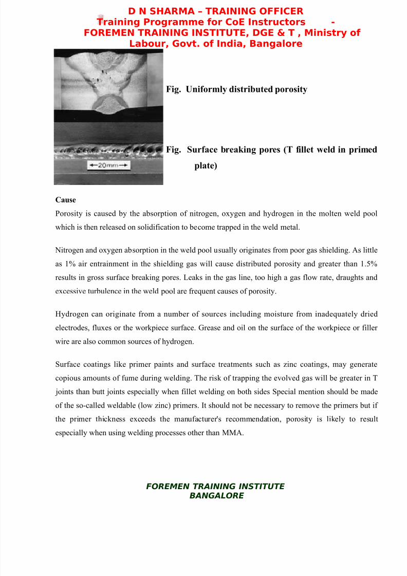
Fig. Uniformly distributed porosity
Fig. Surface breaking pores (T fillet weld in primed
plate)
Cause Porosity is caused by the absorption of nitrogen, oxygen and hydrogen in the molten weld pool
which is then released on solidification to become trapped in the weld metal.
Nitrogen and oxygen absorption in the weld pool usually originates from poor gas shielding. As little
as 1% air entrainment in the shielding gas will cause distributed porosity and greater than 1.5%
results in gross surface breaking pores. Leaks in the gas line, too high a gas flow rate, draughts and
excessive turbulence in the weld pool are frequent causes of porosity.
Hydrogen can originate from a number of sources including moisture from inadequately dried
electrodes, fluxes or the workpiece surface. Grease and oil on the surface of the workpiece or filler
wire are also common sources of hydrogen.
Surface coatings like primer paints and surface treatments such as zinc coatings, may generate
copious amounts of fume during welding. The risk of trapping the evolved gas will be greater in T
joints than butt joints especially when fillet welding on both sides Special mention should be made
of the so-called weldable (low zinc) primers. It should not be necessary to remove the primers but if
the primer thickness exceeds the manufacturer's recommendation, porosity is likely to result
especially when using welding processes other than MMA.
FOREMEN TRAINING INSTITUTEBANGALORE

8/3/2019 PSRAO Welding Defects
http://slidepdf.com/reader/full/psrao-welding-defects 11/34
D N SHARMA – TRAINING OFFICERTraining Programme for CoE Instructors -
FOREMEN TRAINING INSTITUTE, DGE & T , Ministry of Labour, Govt. of India, Bangalore
Prevention
The gas source should be identified and removed as follows:
Air entrainment
- seal any air leak
- avoid weld pool turbulence
- use filler with adequate level of deoxidants
- reduce excessively high gas flow
- avoid draughts
Hydrogen
- dry the electrode and flux- clean and degrease the workpiece surface
Surface coatings
- clean the joint edges immediately before welding
- check that the weldable primer is below the
recommended maximum thickness
Wormholes
Characteristically, wormholes are elongated pores which produce
a herring bone appearance on the radiograph.
Cause
Wormholes are indicative of a large amount of gas being formed which is then trapped in the
solidifying weld metal. Excessive gas will be formed from gross surface contamination or very thick
paint or primer coatings. Entrapment is more likely in crevices such as the gap beneath the vertical
member of a horizontal-vertical, T joint which is fillet welded on both sides.
When welding T joints in primed plates it is essential that the coating thickness on the edge of the
vertical member is not above the manufacturer's recommended maximum, typically 20µm, through
over-spraying.
FOREMEN TRAINING INSTITUTEBANGALORE
Elongated pores or
wormholes

8/3/2019 PSRAO Welding Defects
http://slidepdf.com/reader/full/psrao-welding-defects 12/34
D N SHARMA – TRAINING OFFICERTraining Programme for CoE Instructors -
FOREMEN TRAINING INSTITUTE, DGE & T , Ministry of Labour, Govt. of India, Bangalore
Prevention
Eliminating the gas and cavities prevents wormholes.
Gas generation
- clean the workpiece surfaces
- remove any coatings from the joint area
- check the primer thickness is below the manufacturer's maximum
Joint geometry
- avoid a joint geometry which creates a cavity
Crater pipe
A crater pipe forms during the final solidified weld pool and is often associated with some gas
porosity.
Cause
This imperfection results from shrinkage on weld pool solidification. Consequently, conditions
which exaggerate the liquid to solid volume change will promote its formation. Switching off the
welding current will result in the rapid solidification of a large weld pool.
In TIG welding, autogenous techniques, or stopping the wire before switching off the welding
current, will cause crater formation and the pipe imperfection.
Prevention
Crater pipe imperfection can be prevented by removing the stop or by welder technique.
Removal of stop
- use run-off tag in butt joints
- grind out the stop before continuing with the next electrode or depositing the subsequent
weld run
Welder technique
- progressively reduce the welding current to reduce the weld pool size
FOREMEN TRAINING INSTITUTEBANGALORE

8/3/2019 PSRAO Welding Defects
http://slidepdf.com/reader/full/psrao-welding-defects 13/34
D N SHARMA – TRAINING OFFICERTraining Programme for CoE Instructors -
FOREMEN TRAINING INSTITUTE, DGE & T , Ministry of Labour, Govt. of India, Bangalore
- add filler (TIG) to compensate for the weld pool shrinkage
Porosity susceptibility of materials
Gases likely to cause porosity in the commonly used range of materials are listed in the Table.
Principal gases causing porosity and recommended cleaning methods
Material Gas Cleaning
C-Mn steel Hydrogen, Nitrogen and
Oxygen
Grind to remove scale coatings
Stainless steel Hydrogen Degrease + wire brush + degrease
Aluminium andalloys
Hydrogen Chemical clean + wire brush + degrease +scrape
Copper and alloys Hydrogen, Nitrogen Degrease + wire brush + degrease
Nickel and alloys Nitrogen Degrease + wire brush + degrease
Detection and remedial action
If the imperfections are surface breaking, they can be detected using a penetrant or magnetic particle
inspection technique. For sub surface imperfections, detection is by radiography or ultrasonic
inspection. Radiography is normally more effective in detecting and characterising porosity
imperfections. However, detection of small pores is difficult especially in thick sections.
Remedial action normally needs removal by localised gouging or grinding but if the porosity is
widespread, the entire weld should be removed. The joint should be re-prepared and re-welded as
specified in the agreed procedure.
iv. Inclusions - These can occur when several runs are made along a V join when joining thick plate
using flux cored or flux coated rods and the slag covering a run is not totally removed after every run
before the following run.
As slag is the residue of the flux coating in MMA welding, it is principally a deoxidation product
from the reaction between the flux, air and surface oxide. The slag becomes trapped in the weld
FOREMEN TRAINING INSTITUTEBANGALORE

8/3/2019 PSRAO Welding Defects
http://slidepdf.com/reader/full/psrao-welding-defects 14/34
D N SHARMA – TRAINING OFFICERTraining Programme for CoE Instructors -
FOREMEN TRAINING INSTITUTE, DGE & T , Ministry of Labour, Govt. of India, Bangalore
when two adjacent weld beads are deposited with inadequate overlap and a void is formed. When the
next layer is deposited, the entrapped slag is not melted out. Slag may also become entrapped in
cavities in multi-pass welds through excessive undercut in the weld toe or the uneven surface profile
of the preceding weld runs.
As they both have an effect on the ease of slag removal, the risk of slag imperfections is influenced
by
• Type of flux coating
• Welder technique
The type and configuration of the joint, welding position and access restrictions all have an influence
on the risk of slag imperfections.
Fig. The influence of welder technique on the risk of slag inclusions when welding with a basic
MMA (E7018) electrode
a) Poor (convex) weld bead profile resulted in
pockets of slag being trapped between the weld
runs
FOREMEN TRAINING INSTITUTEBANGALORE

8/3/2019 PSRAO Welding Defects
http://slidepdf.com/reader/full/psrao-welding-defects 15/34
D N SHARMA – TRAINING OFFICERTraining Programme for CoE Instructors -
FOREMEN TRAINING INSTITUTE, DGE & T , Ministry of Labour, Govt. of India, Bangalore
b) Smooth weld bead profile allows the slag to be
readily removed between runs
Type of flux coating
One of the main functions of the flux coating in welding is to produce a slag which will flow freely
over the surface of the weld pool to protect it from oxidation. As the slag affects the handlingcharacteristics of the MMA electrode, its surface tension and freezing rate can be equally important
properties. For welding in the flat and horizontal/vertical positions, a relatively viscous slag is
preferred as it will produce a smooth weld bead profile, is less likely to be trapped and, on
solidifying, is normally more easily removed. For vertical welding, the slag must be more fluid to
flow out to the weld pool surface but have a higher surface tension to provide support to the weld
pool and be fast freezing.
The composition of the flux coating also plays an important role in the risk of slag inclusions
through its effect on the weld bead shape and the ease with which the slag can be removed. A weld
pool with low oxygen content will have a high surface tension producing a convex weld bead with
poor parent metal wetting. Thus, an oxidising flux, containing for example iron oxide, produces a
low surface tension weld pool with a more concave weld bead profile, and promotes wetting into the
parent metal. High silicate flux produces a glass-like slag, often self detaching. Fluxes with a lime
content produce an adherent slag which is difficult to remove.
The ease of slag removal for the principal flux types are:
• Rutile or acid fluxes - large amounts of titanium oxide (rutile) with some silicates. The
oxygen level of the weld pool is high enough to give flat or slightly convex weld bead. The
fluidity of the slag is determined by the calcium fluoride content. Fluoride-free coatings
FOREMEN TRAINING INSTITUTEBANGALORE

8/3/2019 PSRAO Welding Defects
http://slidepdf.com/reader/full/psrao-welding-defects 16/34
D N SHARMA – TRAINING OFFICERTraining Programme for CoE Instructors -
FOREMEN TRAINING INSTITUTE, DGE & T , Ministry of Labour, Govt. of India, Bangalore
designed for welding in the flat position produce smooth bead profiles and an easily removed
slag. The more fluid fluoride slag designed for positional welding is less easily removed.
• Basic fluxes - the high proportion of calcium carbonate (limestone) and calcium fluoride
(fluospar) in the flux reduces the oxygen content of the weld pool and therefore its surface
tension. The slag is more fluid than that produced with the rutile coating. Fast freezing also
assists welding in the vertical and overhead positions but the slag coating is more difficult to
remove.
Consequently, the risk of slag inclusions is significantly greater with basic fluxes due to the inherent
convex weld bead profile and the difficulty in removing the slag from the weld toes especially in
multi-pass welds.
Welder technique
Welding technique has an important role to play in preventing slag inclusions. Electrode
manipulation should ensure adequate shape and degree of overlap of the weld beads to avoid
forming pockets which can trap the slag. Thus, the correct size of electrode for the joint preparation,
the correct angle to the workpiece for good penetration and a smooth weld bead profile are all
essential to prevent slag entrainment.
In multi-pass vertical welding, especially with basic electrodes, care must be taken to fuse out any
remaining minor slag pockets and minimise undercut. When using a weave, a slight dwell at the
extreme edges of the weave will assist sidewall fusion and produce a flatter weld bead profile.
Too high a current together with a high welding speed will also cause sidewall undercutting which
makes slag removal difficult.
It is crucial to remove all slag before depositing the next run. This can be done between runs by
grinding, light chipping or wire brushing. Cleaning tools must be identified for different materials eg
steels or stainless steels, and segregated.
FOREMEN TRAINING INSTITUTEBANGALORE
8/3/2019 PSRAO Welding Defects
http://slidepdf.com/reader/full/psrao-welding-defects 17/34
D N SHARMA – TRAINING OFFICERTraining Programme for CoE Instructors -
FOREMEN TRAINING INSTITUTE, DGE & T , Ministry of Labour, Govt. of India, Bangalore
When welding with difficult electrodes, in narrow vee butt joints or when the slag is trapped through
undercutting, it may be necessary to grind the surface of the weld between layers to ensure complete
slag removal.
Best practice
The following techniques can be used to prevent slag inclusions:
• Use welding techniques to produce smooth weld beads and adequate inter-run fusion to avoid
forming pockets to trap the slag
• Use the correct current and travel speed to avoid undercutting the sidewall which will make
the slag difficult to remove
• Remove slag between runs paying particular attention to removing any slag trapped in
crevices
• Use grinding when welding difficult butt joints otherwise wire brushing or light chipping
may be sufficient to remove the slag.
Acceptance standards
Slag and flux inclusions are linear defects but because they do not have sharp edges compared with
cracks, they may be permitted by specific standards and codes. The limits in steel are specified in BE
EN ISO 5817: 2003 for the three quality levels. Long slag imperfections are not permitted in both
butt and fillet welds for Quality Level B (stringent) and C (moderate). For Quality Level D, butt
welds can have imperfections providing their size is less than half the nominal weld thickness. Short
slag related imperfections are permitted in all three quality levels with limits placed on their size
relative to the butt weld thickness or nominal fillet weld throat thickness.
v. Cracking - This can occur due just to thermal shrinkage or due to a combination of strain
accompanying phase change and thermal shrinkage. In the case of welded stiff frames, a
combination of poor design and inappropriate procedure may result in high residual stresses and
cracking. Where alloy steels or steels with a carbon content greater than about 0.2% are being
FOREMEN TRAINING INSTITUTEBANGALORE
8/3/2019 PSRAO Welding Defects
http://slidepdf.com/reader/full/psrao-welding-defects 18/34
D N SHARMA – TRAINING OFFICERTraining Programme for CoE Instructors -
FOREMEN TRAINING INSTITUTE, DGE & T , Ministry of Labour, Govt. of India, Bangalore
welded, self cooling may be rapid enough to cause some (brittle) martensite to form. This will easily
develop cracks. To prevent these problems a process of pre-heating in stages may be needed and
after welding a slow controlled post cooling in stages will be required. This can greatly increase the
cost of welded joins, but for high strength steels, such as those used in petrochemical plant and
piping, there may well be no alternative.
Solidification Cracking :
This is also called centerline or hot cracking. They are called hot cracks because they occur
immediately after welds are completed and sometimes while the welds are being made. These
defects, which are often caused by sulphur and phosphorus, are more likely to occur in higher carbon
steels. Solidification cracks are normally distinguishable from other types of cracks by the following
features:
• they occur only in the weld metal - although the parent metal is almost always the source of
the low melting point contaminants associated with the cracking
• they normally appear in straight lines along the centreline of the weld bead, but may
occasionally appear as transverse cracking
• solidification cracks in the final crater may have a branching appearance
•
as the cracks are 'open' they are visible to the naked eye
A crack may be defined as a local discontinuity produced by a fracture which can arise from the
stresses generated on cooling or acting on the structure. It is the most serious type of imperfection
found in a weld and should be removed. Cracks not only reduce the strength of the weld through the
reduction in the cross section thickness but also can readily propagate through stress concentration at
the tip, especially under impact loading or during service at low temperature.
Identification
Visual appearance
Solidification cracks are normally readily distinguished from other types of cracks due to the
following characteristic factors:
FOREMEN TRAINING INSTITUTEBANGALORE

8/3/2019 PSRAO Welding Defects
http://slidepdf.com/reader/full/psrao-welding-defects 19/34
D N SHARMA – TRAINING OFFICERTraining Programme for CoE Instructors -
FOREMEN TRAINING INSTITUTE, DGE & T , Ministry of Labour, Govt. of India, Bangalore
• they occur only in the weld metal
• they normally appear as straight lines along the centreline of the weld bead, but may
occasionally appear as transverse cracking depending on the solidification structure
• solidification cracks in the final crater may have a branching appearance
• as the cracks are often 'open', they can be visible to the naked eye
Solidification crack along the centre line of
the weld
On breaking open the weld, the crack surface in steel and nickel alloys may have a blue oxidised
appearance, showing that they were formed while the weld metal was still hot.
Metallography
The cracks form at the solidification boundaries and are characteristically inter dendritic. The
morphology reflects the weld solidification structure and there may be evidence of segregation
associated with the solidification boundary.
Causes
The overriding cause of solidification cracking is that the weld bead in the final stage of
solidification has insufficient strength to withstand the contraction stresses generated as the weld
pool solidifies. Factors which increase the risk include:
• insufficient weld bead size or shape
• welding under high restraint
FOREMEN TRAINING INSTITUTEBANGALORE
8/3/2019 PSRAO Welding Defects
http://slidepdf.com/reader/full/psrao-welding-defects 20/34
D N SHARMA – TRAINING OFFICERTraining Programme for CoE Instructors -
FOREMEN TRAINING INSTITUTE, DGE & T , Ministry of Labour, Govt. of India, Bangalore
• material properties such as a high impurity content or a relatively large amount of shrinkage
on solidification.
Joint design can have a significant influence on the level of residual stresses. Large gaps between
component parts will increase the strain on the solidifying weld metal, especially if the depth of
penetration is small. Therefore, weld beads with a small depth-to-width ratio, such as formed in
bridging a large gap with a wide, thin bead, will be more susceptible to solidification cracking,
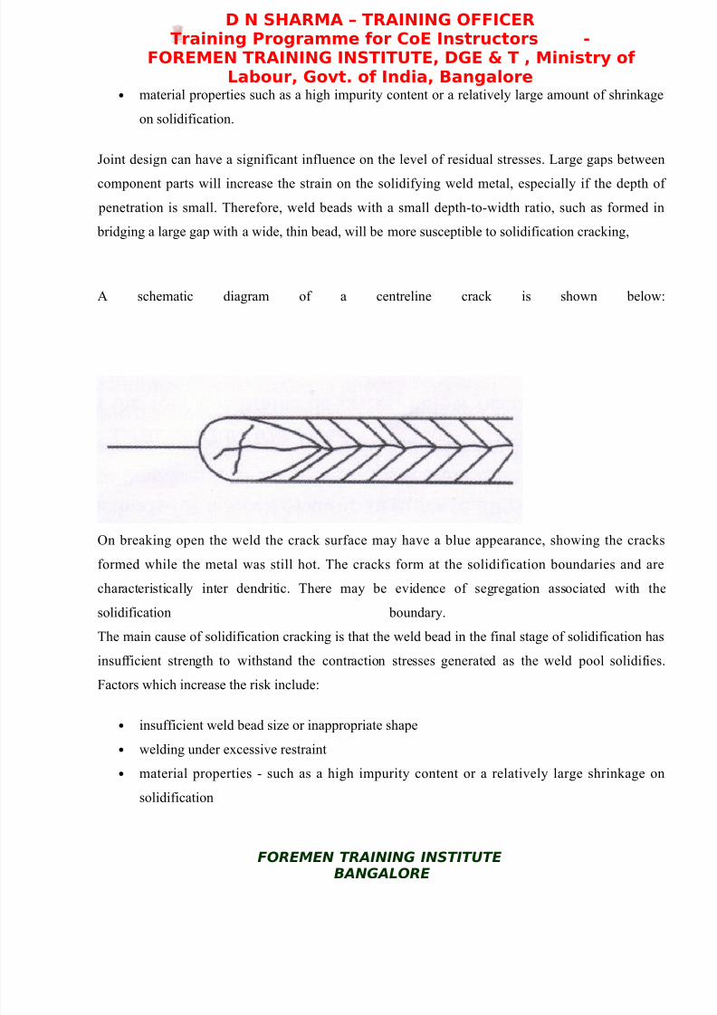
A schematic diagram of a centreline crack is shown below:
On breaking open the weld the crack surface may have a blue appearance, showing the cracks
formed while the metal was still hot. The cracks form at the solidification boundaries and are
characteristically inter dendritic. There may be evidence of segregation associated with the
solidification boundary.
The main cause of solidification cracking is that the weld bead in the final stage of solidification has
insufficient strength to withstand the contraction stresses generated as the weld pool solidifies.
Factors which increase the risk include:
• insufficient weld bead size or inappropriate shape
• welding under excessive restraint
• material properties - such as a high impurity content or a relatively large shrinkage on
solidification
FOREMEN TRAINING INSTITUTEBANGALORE

8/3/2019 PSRAO Welding Defects
http://slidepdf.com/reader/full/psrao-welding-defects 21/34
D N SHARMA – TRAINING OFFICERTraining Programme for CoE Instructors -
FOREMEN TRAINING INSTITUTE, DGE & T , Ministry of Labour, Govt. of India, Bangalore
Joint design can have an influence on the level of residual stresses. Large gaps between components
will increase the strain on the solidifying weld metal, especially if the depth of penetration is small.
Hence weld beads with a small depth to width ratio, such as is formed when bridging a large wide
gap with a thin bead, will be more susceptible to solidification cracking.
In steels, cracking is associated with impurities, particularly sulphur and phosphorus and is promoted
by carbon, whereas manganese and sulphur can help to reduce the risk. To minimise the risk of
cracking, fillers with low carbon and impurity levels and a relatively high manganese content are
preferred. As a general rule, for carbon manganese steels, the total sulphur and phosphorus content
should be no greater than 0.06%. However when welding a highly restrained joint using high
strength steels, a combined level below 0.03% might be needed.
Weld metal composition is dominated by the filler and as this is usually cleaner than the metal being
welded, cracking is less likely with low dilution processes such as MMA and MIG. Parent metal
composition becomes more important with autogenous welding techniques, such as TIG with no
filler.
Avoiding Solidification Cracking :
Apart from choice of material and filler, the main techniques for avoiding solidification cracking are:
• control the joint fit up to reduce the gaps
• clean off all contaminants before welding
• ensure that the welding sequence will not lead to a buildup of thermally induced stresses
• choose welding parameters to produce a weld bead with adequate depth to width ratio or with
sufficient throat thickness (fillet weld) to ensure the bead has sufficient resistance to
solidification stresses. Recommended minimum depth to width ratio is 0.5:1
•
avoid producing too large a depth to width ratio which will encourage segregation andexcessive transverse strains. As a rule, weld beads with a depth to width ratio exceeds 2:1
will be prone to solidification cracking
• avoid high welding speeds (at high current levels) which increase segregation and stress
levels accross the weld bead
• at the run stop, ensure adequate filling of the crater to avoid an unfavourable concave shape
FOREMEN TRAINING INSTITUTEBANGALORE
8/3/2019 PSRAO Welding Defects
http://slidepdf.com/reader/full/psrao-welding-defects 22/34
D N SHARMA – TRAINING OFFICERTraining Programme for CoE Instructors -
FOREMEN TRAINING INSTITUTE, DGE & T , Ministry of Labour, Govt. of India, Bangalore
Hydrogen induced cracking (HIC) - also referred to as hydrogen cracking or hydrogen assisted
cracking, can occur in steels during manufacture, during fabrication or during service. When HIC
occurs as a result of welding, the cracks are in the heat affected zone (HAZ) or in the weld metal
itself.
Four requirements for HIC to occur are:
• a) Hydrogen be present, this may come from moisture in any flux or from other sources. It is
absorbed by the weld pool and diffuses int o the HAZ.
• b) A HAZ microstructure susceptible to hydrogen cracking.
• c) Tensile stresses act on the weld
• d) The assembly has cooled to close to ambient - less than 150oC
HIC in the HAZ is often at the weld toe, but can be under the weld bead or at the weld root. In fillet
welds cracks are normally parallel to the weld run but in butt welds cracks can be transverse to the
welding direction.
Hydrogen cracking may also be called cold cracking or delayed cracking. The principal
distinguishing feature of this type of crack is that it occurs in ferritic steels, most often immediately
on welding or a short time after welding.
In this issue, the characteristic features and principal causes of hydrogen cracks are described.
Identification
Visual appearance
Hydrogen cracks can be usually be distinguished due to the following characteristics:
• In C-Mn steels, the crack will normally originate in the heat affected zone (HAZ), but may
extend into the weld metal ..
• Cracks can also occur in the weld bead, normally transverse to the welding direction at an
angle of 45° to the weld surface. They follow a jagged path, but may be non-branching.
FOREMEN TRAINING INSTITUTEBANGALORE

8/3/2019 PSRAO Welding Defects
http://slidepdf.com/reader/full/psrao-welding-defects 23/34
D N SHARMA – TRAINING OFFICERTraining Programme for CoE Instructors -
FOREMEN TRAINING INSTITUTE, DGE & T , Ministry of Labour, Govt. of India, Bangalore
• In low alloy steels, the cracks can be transverse to the weld, perpendicular to the weld
surface, but are non-branching, and essentially planar.
Hydrogen cracks originating in the HAZ and weld
metal. (Note that the type of cracks shown would not be
expected to form in the same weldment.)
On breaking open the weld (prior to any heat treatment), the surface of the cracks will normally not
be oxidised, even if they are surface breaking, indicating they were formed when the weld was at or
near ambient temperature. A slight blue tinge may be seen from the effects of preheating or welding
heat.
Metallography
Cracks which originate in the HAZ are usually associated with the coarse grain region. The cracks
can be intergranular, transgranular or a mixture. Intergranular cracks are more likely to occur in the
harder HAZ structures formed in low alloy and high carbon steels. Transgranular cracking is more
often found in C-Mn steel structures.
In fillet welds, cracks in the HAZ are usually associated with the weld root and parallel to the weld.
In butt welds, the HAZ cracks are normally oriented parallel to the weld bead.
FOREMEN TRAINING INSTITUTEBANGALORE
8/3/2019 PSRAO Welding Defects
http://slidepdf.com/reader/full/psrao-welding-defects 24/34
D N SHARMA – TRAINING OFFICERTraining Programme for CoE Instructors -
FOREMEN TRAINING INSTITUTE, DGE & T , Ministry of Labour, Govt. of India, Bangalore
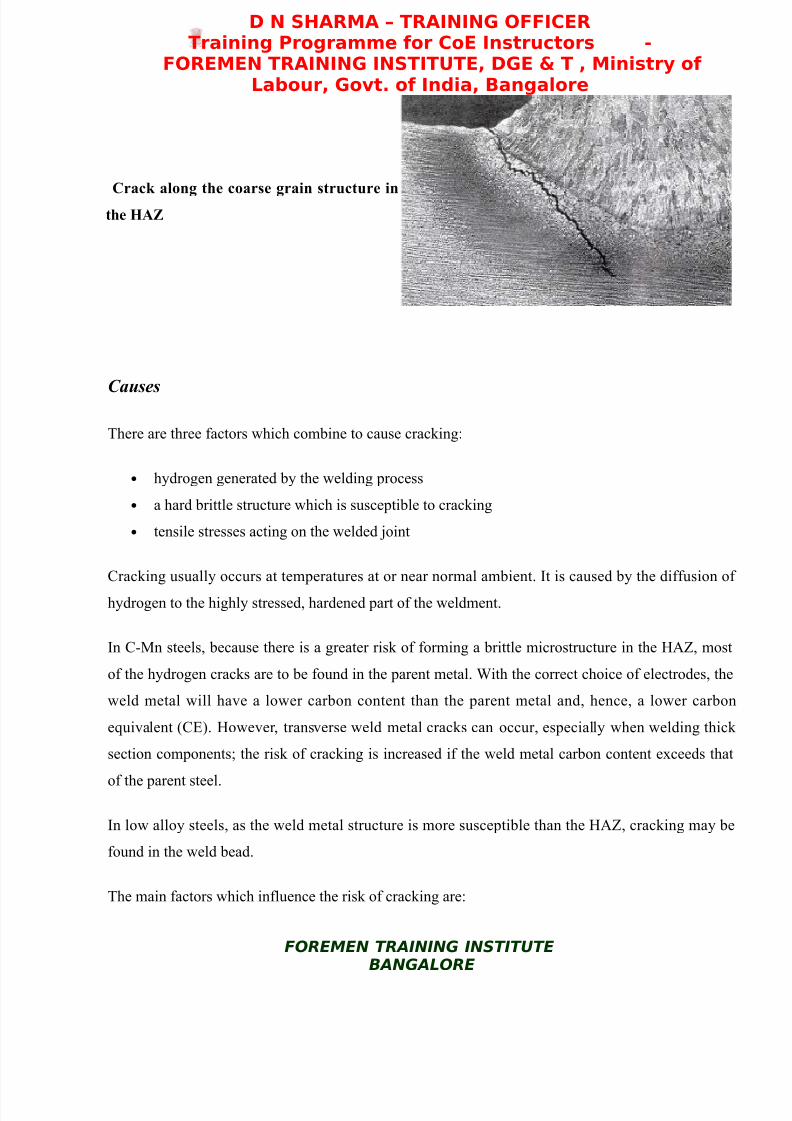
Crack along the coarse grain structure inthe HAZ
Causes
There are three factors which combine to cause cracking:
• hydrogen generated by the welding process
• a hard brittle structure which is susceptible to cracking
• tensile stresses acting on the welded joint
Cracking usually occurs at temperatures at or near normal ambient. It is caused by the diffusion of
hydrogen to the highly stressed, hardened part of the weldment.
In C-Mn steels, because there is a greater risk of forming a brittle microstructure in the HAZ, most
of the hydrogen cracks are to be found in the parent metal. With the correct choice of electrodes, the
weld metal will have a lower carbon content than the parent metal and, hence, a lower carbon
equivalent (CE). However, transverse weld metal cracks can occur, especially when welding thick
section components; the risk of cracking is increased if the weld metal carbon content exceeds that
of the parent steel.
In low alloy steels, as the weld metal structure is more susceptible than the HAZ, cracking may be
found in the weld bead.
The main factors which influence the risk of cracking are:
FOREMEN TRAINING INSTITUTEBANGALORE

8/3/2019 PSRAO Welding Defects
http://slidepdf.com/reader/full/psrao-welding-defects 25/34
D N SHARMA – TRAINING OFFICERTraining Programme for CoE Instructors -
FOREMEN TRAINING INSTITUTE, DGE & T , Ministry of Labour, Govt. of India, Bangalore
• weld metal hydrogen
• parent material composition
• parent material thickness
• stresses acting on the weld
• heat input
Weld metal hydrogen content
The principal source of hydrogen is moisture contained in the flux, i.e. the coating of MMA
electrodes, the flux in cored wires and the flux used in submerged arc welding. The amount of
hydrogen generated is influenced by the electrode type. Basic electrodes normally generate less
hydrogen than rutile and cellulosic electrodes.
It is important to note that there can be other significant sources of hydrogen, e.g. moisture from the
atmosphere or from the material where processing or service history has left the steel with a
significant level of hydrogen. Hydrogen may also be derived from the surface of the material or the
consumable.
vi Undercutting - In this case the thickness of one (or both) of the sheets is reduced at the toe of the
weld. This is due to incorrect settings / procedure. There is already a stress concentration at the toe
of the weld and any undercut will reduce the strength of the join.
vii Lamellar tearing - This is mainly a problem with low quality steels. It occurs in plate that has a
low ductility in the through thickness direction, which is caused by non metallic inclusions, such as
suphides and oxides that have been elongated during the rolling process. These inclusions mean that
the plate can not tolerate the contraction stresses in the short transverse direction.
Lamellar tearing can occur in both fillet and butt welds, but the most vulnerable joints are 'T' and
corner joints, where the fusion boundary is parallel to the rolling plane.
These problem can be overcome by using better quality steel, 'buttering' the weld area with a ductile
material and possibly by redesigning the joint.
FOREMEN TRAINING INSTITUTEBANGALORE
8/3/2019 PSRAO Welding Defects
http://slidepdf.com/reader/full/psrao-welding-defects 26/34
D N SHARMA – TRAINING OFFICERTraining Programme for CoE Instructors -
FOREMEN TRAINING INSTITUTE, DGE & T , Ministry of Labour, Govt. of India, Bangalore
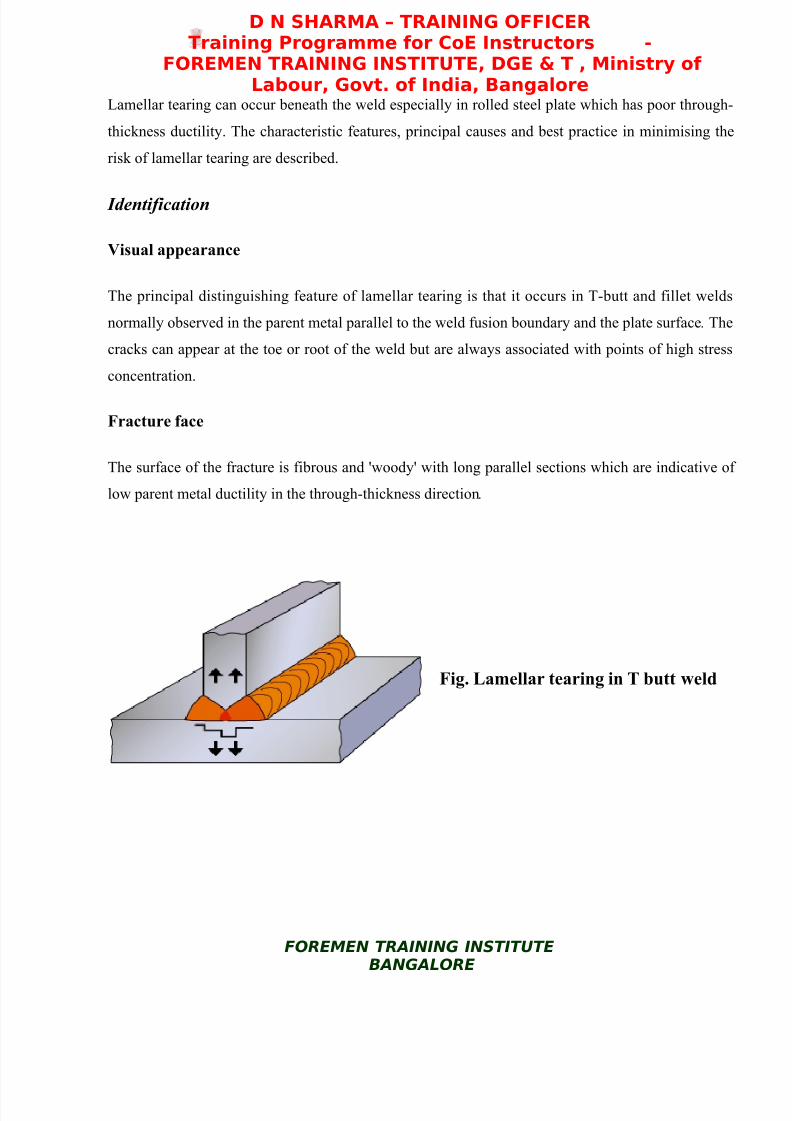
Lamellar tearing can occur beneath the weld especially in rolled steel plate which has poor through-
thickness ductility. The characteristic features, principal causes and best practice in minimising the
risk of lamellar tearing are described.
Identification
Visual appearance
The principal distinguishing feature of lamellar tearing is that it occurs in T-butt and fillet welds
normally observed in the parent metal parallel to the weld fusion boundary and the plate surface . The
cracks can appear at the toe or root of the weld but are always associated with points of high stress
concentration.
Fracture face
The surface of the fracture is fibrous and 'woody' with long parallel sections which are indicative of
low parent metal ductility in the through-thickness direction.
Fig. Lamellar tearing in T butt weld
FOREMEN TRAINING INSTITUTEBANGALORE
8/3/2019 PSRAO Welding Defects
http://slidepdf.com/reader/full/psrao-welding-defects 27/34
D N SHARMA – TRAINING OFFICERTraining Programme for CoE Instructors -
FOREMEN TRAINING INSTITUTE, DGE & T , Ministry of Labour, Govt. of India, Bangalore
Metallography
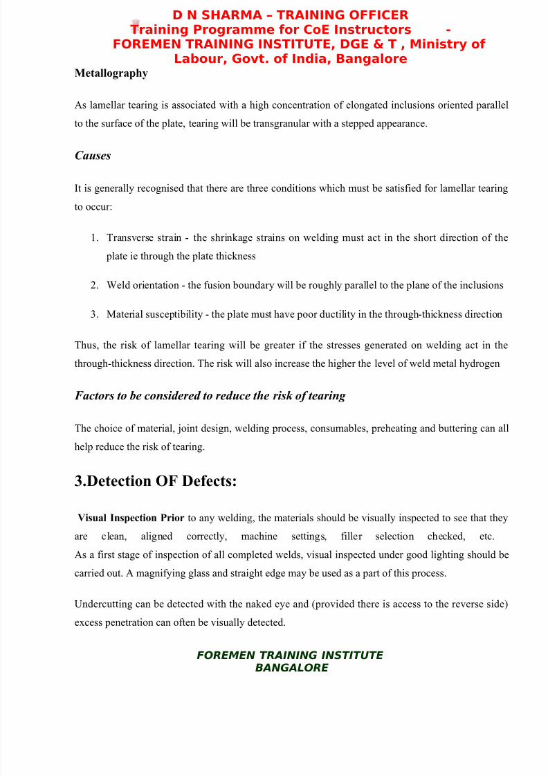
As lamellar tearing is associated with a high concentration of elongated inclusions oriented parallel
to the surface of the plate, tearing will be transgranular with a stepped appearance.
Causes
It is generally recognised that there are three conditions which must be satisfied for lamellar tearing
to occur:
1. Transverse strain - the shrinkage strains on welding must act in the short direction of the
plate ie through the plate thickness
2. Weld orientation - the fusion boundary will be roughly parallel to the plane of the inclusions
3. Material susceptibility - the plate must have poor ductility in the through-thickness direction
Thus, the risk of lamellar tearing will be greater if the stresses generated on welding act in the
through-thickness direction. The risk will also increase the higher the level of weld metal hydrogen
Factors to be considered to reduce the risk of tearing
The choice of material, joint design, welding process, consumables, preheating and buttering can all
help reduce the risk of tearing.
3.Detection OF Defects:
Visual Inspection Prior to any welding, the materials should be visually inspected to see that they
are clean, aligned correctly, machine settings, filler selection checked, etc.
As a first stage of inspection of all completed welds, visual inspected under good lighting should be
carried out. A magnifying glass and straight edge may be used as a part of this process.
Undercutting can be detected with the naked eye and (provided there is access to the reverse side)
excess penetration can often be visually detected.
FOREMEN TRAINING INSTITUTEBANGALORE

8/3/2019 PSRAO Welding Defects
http://slidepdf.com/reader/full/psrao-welding-defects 28/34
D N SHARMA – TRAINING OFFICERTraining Programme for CoE Instructors -
FOREMEN TRAINING INSTITUTE, DGE & T , Ministry of Labour, Govt. of India, Bangalore
Liquid Penetrant Inspection :Serious cases of surface cracking can be detected by the naked eye
but for most cases some type of aid is needed and the use of dye penetrant methods are quite
efficient when used by a trained operator.
This procedure is as follows:
• Clean the surface of the weld and the weld vicinity
• Spray the surface with a liquid dye that has good penetrating properties
• Carefully wipe all the die off the surface
• Spray the surface with a white powder
• Any cracks will have trapped some die which will weep out and discolour the white coating
and be clearly visible
X - Ray Inspection :
Sub-surface cracks and inclusions can be detected 'X' ray examination. This is expensive, but for
safety critical joints - eg in submarines and nuclear power plants - 100% 'X' ray examination of
welded joints will normally be carried out.
Ultrasonic Inspection :
Surface and sub-surface defects can also be detected by ultrasonic inspection. This involves directing
a high frequency sound beam through the base metal and weld on a predictable path. When the beam
strikes a discontinuity some of it is reflected beck. This reflected beam is received and amplified and
processed and from the time delay, the location of a flaw estimated.
Porosity, however, in the form of numerous gas bubbles causes a lot of low amplitude reflections
which are difficult to separate from the background noise.
Results from any ultrasonic inspection require skilled interpretation.
Magnetic Particle Inspection :
This process can be used to detect surface and slightly sub-surface cracks in ferro-magnetic materials
(it can not therefore be used with austenitic stainless steels).
The process involves placing a probe on each side of the area to be inspected and passing a high
FOREMEN TRAINING INSTITUTEBANGALORE

8/3/2019 PSRAO Welding Defects
http://slidepdf.com/reader/full/psrao-welding-defects 29/34
D N SHARMA – TRAINING OFFICERTraining Programme for CoE Instructors -
FOREMEN TRAINING INSTITUTE, DGE & T , Ministry of Labour, Govt. of India, Bangalore
current between them. This produces a magnetic flux at right angles to the flow of the current. When
these lines of force meet a discontinuity, such as a longitudinal crack, they are diverted and leak
through the surface, creating magnetic poles or points of attraction. A magnetic powder dusted onto
the surface will cling to the leakage area more than elsewhere, indicating the location of any
discontinuities.
This process may be carried out wet or dry, the wet process is more sensitive as finer particles may
be used which can detect very small defects. Fluorescent powders can also be used to enhance
sensitivity when used in conjunction with ultra violet illumination.
4. Repair :
Any detected cracks must be ground out and the area re-welded to give the required profile and then
the joint must be inspected again.
He above defects are again treated pictographically below;
Welding Discontinuities
Incomplete Fusion - A weld
discontinuity in which fusion
did not occur between weldmetal and fusion faces or
adjoining weld beads.
Undercut - A groove melted
into the base metal adjacent tothe weld toe or weld root and
left unfilled by weld metal.
Overlap - The protrusion of
weld metal beyond the weldtoe or weld root.
FOREMEN TRAINING INSTITUTEBANGALORE

8/3/2019 PSRAO Welding Defects
http://slidepdf.com/reader/full/psrao-welding-defects 30/34
D N SHARMA – TRAINING OFFICERTraining Programme for CoE Instructors -
FOREMEN TRAINING INSTITUTE, DGE & T , Ministry of Labour, Govt. of India, Bangalore
Underfill - A condition inwhich the weld face or root
surface extends below the
adjacent surface of the basemetal.
Incomplete Joint Penetration -
A joint root condition in a
groove weld in which weldmetal does not extend through
the joint thickness
Partial joint penetration groove welds are commonly specified in lowly loaded structures. However,
incomplete joint penetration when a full penetration joint is required, as depicted above, would because for rejection. A fix for an incomplete penetration joint would be to back gouge and weld from
the other side. Another acceptable partial penetration joint is shown below.
Partial penetration joint on theleft without discontinuities isan acceptable condition where
appropriate. Appropriate
engineering decisions need to be applied to determine what
type of joint should be
specified for a givenapplication.
Engineering should be contacted to determine whether partial penetration or full penetration joints
are appropriate for a particular situation.
Above are several different representations of weld Cracking
Below is a representation of a convex fillet weld without discontinuities.
FOREMEN TRAINING INSTITUTEBANGALORE
8/3/2019 PSRAO Welding Defects
http://slidepdf.com/reader/full/psrao-welding-defects 31/34
D N SHARMA – TRAINING OFFICERTraining Programme for CoE Instructors -
FOREMEN TRAINING INSTITUTE, DGE & T , Ministry of Labour, Govt. of India, Bangalore
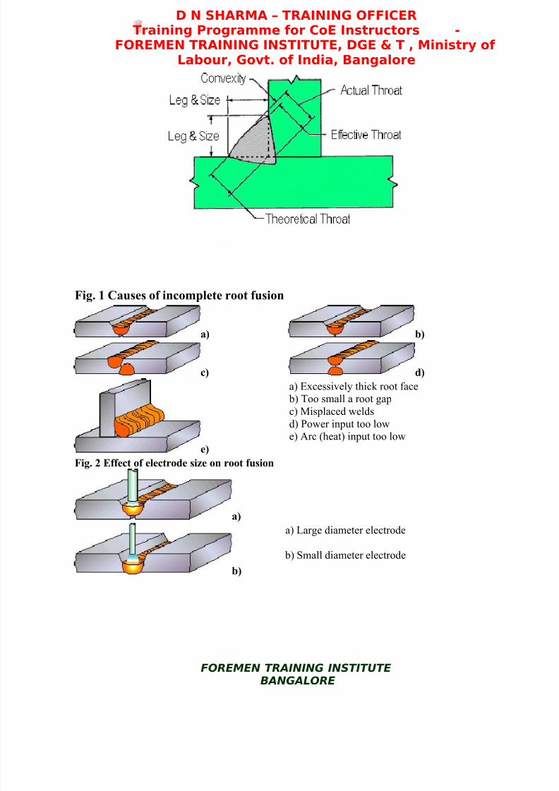
Fig. 1 Causes of incomplete root fusion
a) b)
c) d)
e)
a) Excessively thick root face b) Too small a root gap
c) Misplaced weldsd) Power input too lowe) Arc (heat) input too low
Fig. 2 Effect of electrode size on root fusion
a)
b)
a) Large diameter electrode
b) Small diameter electrode
FOREMEN TRAINING INSTITUTEBANGALORE

8/3/2019 PSRAO Welding Defects
http://slidepdf.com/reader/full/psrao-welding-defects 32/34
D N SHARMA – TRAINING OFFICERTraining Programme for CoE Instructors -
FOREMEN TRAINING INSTITUTE, DGE & T , Ministry of Labour, Govt. of India, Bangalore
Recommended joint configurations to reduce the risk of lamellar tearing
Fig. a
Fig. b
Fig. c
Fig. d
DISTORTION
Welding involves highly localized heating of the metal being joined together. The temperature
distribution in the weldment is therefore nonuniform. Normally, the weld metal and the heat
affected zone (HAZ) are at temperatures substantially above that of the unaffected base metal. Upon
cooling, the weld pool solidifies and shrinks, exerting stresses on the surrounding weld metal and
HAZ.
FOREMEN TRAINING INSTITUTEBANGALORE
8/3/2019 PSRAO Welding Defects
http://slidepdf.com/reader/full/psrao-welding-defects 33/34
D N SHARMA – TRAINING OFFICERTraining Programme for CoE Instructors -
FOREMEN TRAINING INSTITUTE, DGE & T , Ministry of Labour, Govt. of India, Bangalore
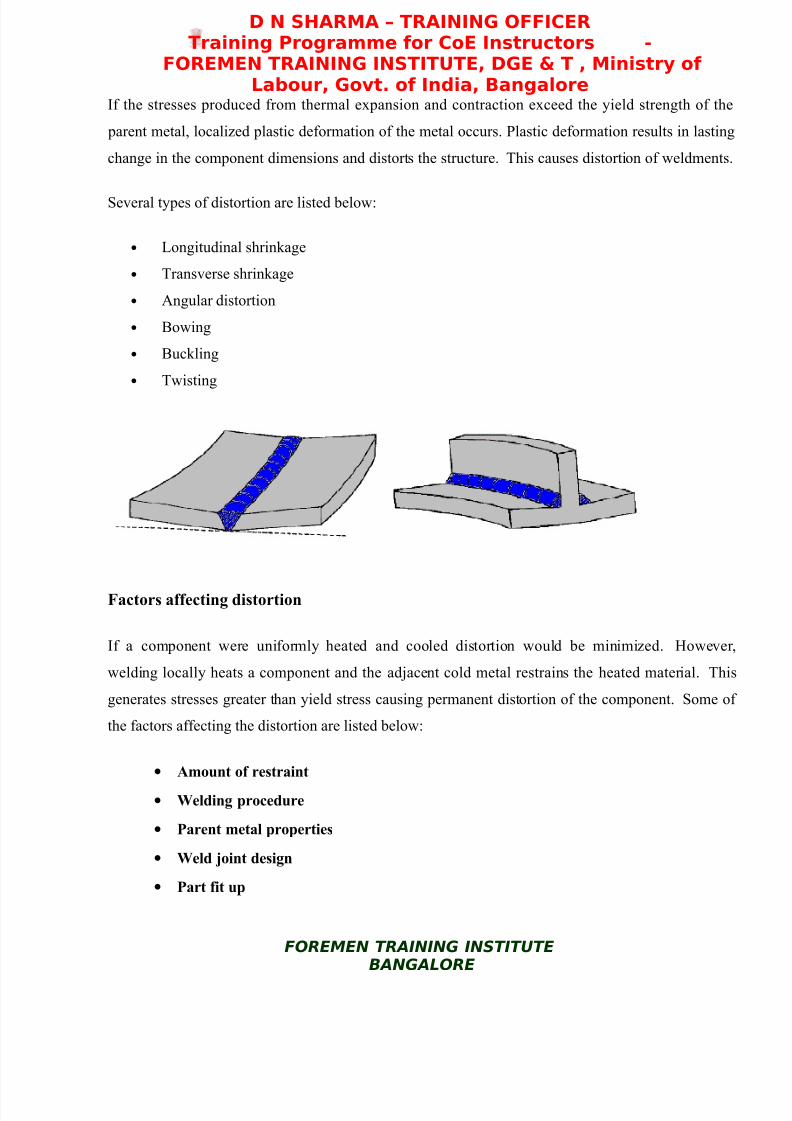
If the stresses produced from thermal expansion and contraction exceed the yield strength of the
parent metal, localized plastic deformation of the metal occurs. Plastic deformation results in lasting
change in the component dimensions and distorts the structure. This causes distortion of weldments.
Several types of distortion are listed below:
• Longitudinal shrinkage
• Transverse shrinkage
• Angular distortion
• Bowing
• Buckling
• Twisting
Factors affecting distortion
If a component were uniformly heated and cooled distortion would be minimized. However,
welding locally heats a component and the adjacent cold metal restrains the heated material. This
generates stresses greater than yield stress causing permanent distortion of the component. Some of
the factors affecting the distortion are listed below:
• Amount of restraint
• Welding procedure
• Parent metal properties
• Weld joint design
• Part fit up
FOREMEN TRAINING INSTITUTEBANGALORE
8/3/2019 PSRAO Welding Defects
http://slidepdf.com/reader/full/psrao-welding-defects 34/34
D N SHARMA – TRAINING OFFICERTraining Programme for CoE Instructors -
FOREMEN TRAINING INSTITUTE, DGE & T , Ministry of Labour, Govt. of India, Bangalore
Restraint can be used to minimize distortion. Components welded without any external restraint are
free to move or distort in response to stresses from welding. It is not unusual for many shops to
clamp or restrain components to be welded in some manner to prevent movement and
distortion. This restraint does result in higher residual stresses in the components.
Welding procedure impacts the amount of distortion primarily due to the amount of the heat input
produced. The welder has little control on the heat input specified in a welding procedure. This
does not prevent the welder from trying to minimize distortion. While the welder needs to provide
adequate weld metal, the welder should not needlessly increase the total weld metal volume added to
a weldment.
Parent metal properties, which have an effect on distortion, are coefficient of thermal expansion and
specific heat of the material. The coefficient of thermal expansion of the metal affects the degree of
thermal expansion and contraction and the associated stresses that result from the welding process.
This in turn determines the amount of distortion in a component.
Weld joint design will effect the amount of distortion in a weldment. Both butt and fillet joints may
experience distortion. However, distortion is easier to minimize in butt joints.
Part fit up should be consistent to fabricate foreseeable and uniform shrinkage. Weld joints should
be adequately and consistently tacked to minimize movement between the parts being joined by
welding.