Embed Size (px)
Citation preview

8/10/2019 Defects Welding
http://slidepdf.com/reader/full/defects-welding 1/206
Non Destructive Testing
NDT is concerned with finding defects. So, a knowledge of the types of
defects is essential, both to determine the best NDT technique to use and to
help to determine the type of defect and to assess how significant the defect
is.Defects are formed during:
Primary processing – Casting, Forging, Rolling, Welding etc.
Secondary processing – Heat treatment, Machining etc
Service induced – fatigue cracking, stress corrosion cracking.

8/10/2019 Defects Welding
http://slidepdf.com/reader/full/defects-welding 2/206
Defects in Wrought Products
Wrought products are materials or components that have been produced by
mechanical working processes such as forging, rolling or extrusion. The
other basic method of producing shapes is casting, where molten metal is
poured into a mould of the required shape and it solidifies to take the shapeof the mould cavity.
Defects in wrought products include the following:
Laps
Seams
Pipe/laminationInclusions
Hydrogen flakes
Forging bursts

8/10/2019 Defects Welding
http://slidepdf.com/reader/full/defects-welding 3/206
Extrusions
In direct extrusion a ram forces the preheated aluminum billet through the
die. This can be likened to squeezing toothpaste out of a tube. Using this
method it is possible to extrude up to six lengths from one die.Direct extrusion is usually used for the manufacture of profiled sections and
hollow bar products.
Indirect extrusion is the reverse of direct extrusion, the die being forced on
to the billet rather than the billet being forced through the die.

8/10/2019 Defects Welding
http://slidepdf.com/reader/full/defects-welding 4/206
Extrusions When introduced into production, pre
cut billets (slugs) are heated in furnace
up to extrusion temperature. Billets, as
input material, are pressed in a
horizontal powerful hydraulic press.

8/10/2019 Defects Welding
http://slidepdf.com/reader/full/defects-welding 5/206
The Press supplies the force
necessary to squeeze the billet
through the extrusion die. It
consists of:
The container where the billet
is put under pressure.The main cylinder with the ram
for pushing the billet into the
container and through the die.
The front platen giving counter
support to the die package.
The main columns fixing the
front platen and the cylinder
together.
The die is supported by a
series of back dies or backers
and bolsters for transferring the
main press load to the front
platen.

8/10/2019 Defects Welding
http://slidepdf.com/reader/full/defects-welding 6/206
Forging The forging process involves deforming a hot work piece with dies attached to
a mechanical or hydraulic press. Forging is used to produce some of the
highly stressed parts in tools and aircraft because forged parts have high
resistance to shock and fatigue. Since forged parts are plastically deformed,
they are stronger and more ductile than parts produced with die-casting.

8/10/2019 Defects Welding
http://slidepdf.com/reader/full/defects-welding 7/206
Rolling

8/10/2019 Defects Welding
http://slidepdf.com/reader/full/defects-welding 8/206
Rolling

8/10/2019 Defects Welding
http://slidepdf.com/reader/full/defects-welding 9/206
Casting
Tempered sand is packed onto wood or metal pattern halves, removed from
the pattern, and assembled with or without cores, and metal is poured into
resultant cavities. Various core materials can be used. Molds are broken to
remove castings. Specialized binders now in use can improve tolerancesand surface finish. Most metals are castable.
If the casting is to be hollow, as in the case of pipe fittings, additional
patterns, referred to as cores, are used to form these cavities. Cores are
forms, usually made of sand, which are placed into a mold cavity to form the
interior surfaces of castings. Thus the void space between the core and
mold-cavity surface is what eventually becomes the casting.

8/10/2019 Defects Welding
http://slidepdf.com/reader/full/defects-welding 10/206
The pattern is a
physical model of the
casting used to make
the mold.
The mold is made by
packing some readilyformed aggregate
material, such as
molding sand, around
the pattern. When the
pattern is withdrawn,
its imprint provides
the mold cavity, which
is ultimately filled
with metal to become
the casting.

8/10/2019 Defects Welding
http://slidepdf.com/reader/full/defects-welding 11/206
Laps
These are found in rolled or forged products. Laps in hot rolled bars are
longitudinally oriented folds on the surface of the product due to rolling over
of projections on the surface.

8/10/2019 Defects Welding
http://slidepdf.com/reader/full/defects-welding 12/206
Laps
In cross-section laps tend to „hook‟ under the surface. They generally
contain oxide or scale and may be partially welded at the tip.Because of their method of formation, laps tend to be very long although
they are usually quite shallow, say less than 1 mm in depth.
The preferred NDT to detect laps in steel is magnetic particle testing. Eddy
current testing is the best method for non-ferrous metals. Penetrant testing
is generally not suitable as laps usually contain scale or oxide.

8/10/2019 Defects Welding
http://slidepdf.com/reader/full/defects-welding 13/206

8/10/2019 Defects Welding
http://slidepdf.com/reader/full/defects-welding 14/206
Pipes and laminations
Pipe and lamination defects are a by-product of ingot steel production.Modern steelmaking practice uses continuous casting technology where
these defects are much less common.
Both pipe and laminations defects are centrally located and, in the case of
lamination the defect is planar and parallel to the flat faces. The preferred
NDT method for pipe and lamination is ultrasonic testing. In smaller sections
pipe may also be detected by radiography

8/10/2019 Defects Welding
http://slidepdf.com/reader/full/defects-welding 15/206
Pipe / lamination
These two defects are grouped together since they have the same origin.Piping is a cavity formed during solidification of an ingot due to the fact that
when molten metal solidifies there is a reduction in volume called shrinkage.
Piping may be open at the ingot top when it is called a primary pipe. It may
also be within the ingot when it is called a secondary pipe. Ingot pipe can
persist in material right through a rolling sequence from the ingot stage tofine wire or thin sheet to produce a pipe or lamination defect. In some cases
secondary pipe can weld up and so disappear during rolling operations.
The difference between pipe and lamination is that pipe occurs in sections
such as rounds, hexagons and squares and lamination occurs in flat
products such as plate or sheet.

8/10/2019 Defects Welding
http://slidepdf.com/reader/full/defects-welding 16/206
Inclusions
These are non-metallic material such
as:
Products of steelmaking reactions, for
example, sulphides, silicates, slag.Refractory material dispersed through
the metal.
Inclusions are always present to some
degree in steel but are of concern in
gross form or at excessive levels.
Inclusions tend to be orientated in the
direction of metal working.
Effect of rolling on inclusions
The preferred NDT method for
detecting gross inclusions is ultrasonic
testing. For smaller sectionsradiography may be used.

8/10/2019 Defects Welding
http://slidepdf.com/reader/full/defects-welding 17/206

8/10/2019 Defects Welding
http://slidepdf.com/reader/full/defects-welding 18/206
Forging bursts
These are surface or internal ruptures
due to the inability of metal to
withstand internal tensile stresses
generated in forging. They arepromoted by such factors as
processing at too low a temperature,
excessive working in forging or forging
steels with higher sulphur contents
(hot shortness).
Bursts are often large and seldom
heal during subsequent working. They
may take the form of an open cavity or
a tight faced crack and may be
longitudinally or transversely
orientated. The best method ofdetection is ultrasonic, or radiography
in smaller sections.

8/10/2019 Defects Welding
http://slidepdf.com/reader/full/defects-welding 19/206
Cracks hese are surface or
internal ruptures due to the
inability of metal to withstand
internal tensile stresses
generated in forging. They arepromoted by such factors as
processing at too low a
temperature, excessive working
in forging or forging steels with
higher sulphur contents (hot
shortness).
Bursts are often large and
seldom heal during subsequent
working. They may take the form
of an open cavity or a tight faced
crack and may be longitudinallyor transversely orientated. The
best method of detection is
ultrasonic, or radiography in
smaller sections.

8/10/2019 Defects Welding
http://slidepdf.com/reader/full/defects-welding 20/206
Defects in Cast Products
include the following :
Porosity
Gas holes
Air locksShrinkage cavities
Hot tears
Cracks
Inclusions
Cold shuts

8/10/2019 Defects Welding
http://slidepdf.com/reader/full/defects-welding 21/206
Defects in Cast Products
Defects in cast products include the following:
Porosity
Gas holes
Air locksShrinkage cavities
Hot tears
Cracks
Inclusions
Cold shuts

8/10/2019 Defects Welding
http://slidepdf.com/reader/full/defects-welding 22/206
Porosity
Porosity is small smooth-faced cavities, generally smaller than 1.5 mm
diameter. Porosity is usually caused by the release of gas from the molten
metal as it cools. Gases such as hydrogen may be dissolved in the liquid
metal. As the metal cools, the dissolved gas separates out to form bubbles,
which are trapped in the solidifying metal.
Porosity
The preferred NDT method for detecting porosity is radiography. Ultrasonic
testing may also detect porosity.

8/10/2019 Defects Welding
http://slidepdf.com/reader/full/defects-welding 23/206
Gas holes
The main distinction between gas holes and porosity is the size. Gas holes
are smooth-faced cavities greater than 1.5 mm diameter. Typical causes are:
Evolution of gas from molten metal during solidification.
Gas trapped as the molten metal enters the mould.
Reactions between the metal and the mould, also known as blowholes.
Again the best method to detect gas holes is radiography. Ultrasonic testing
can also be used. Blowholes are similar in origin to porosity in welds.
Dissolved gases precipitate from the liquid metal and leave rounded gas
filled cavities. Vacuum degassing of liquid metal before pouring has greatly
reduced the occurrence of blowholes.

8/10/2019 Defects Welding
http://slidepdf.com/reader/full/defects-welding 24/206

8/10/2019 Defects Welding
http://slidepdf.com/reader/full/defects-welding 25/206
Shrinkage cavities
Shrinkage cavities form during solidification
as a result of the reduction in volume when
metal changes from the liquid to the solid
state. Shrinkage cavities occur in situationswhere molten metal in not available to
compensate for the volume decrease
during solidification. Shrinkage flaws
typically occur where there is a localised
variation in section thickness but may occur
in parallel sections where penetration of the
liquid feed metal is difficult.
Shrinkage defects vary in form from open
cavities (piping) to branched interconnected
fine cavities. The defects tend to have a
rough surface profile.Formation of shrinkage cavities
Once again the best method to detect gas
holes is radiography. Ultrasonic testing
again can also be used.

8/10/2019 Defects Welding
http://slidepdf.com/reader/full/defects-welding 26/206
Cracks
These are discontinuities due to the fracture of the metal during or after
solidification.
A particular type of cracking is „stress cracks‟ which are approximatelystraight and which form when the metal has become completely solid as
shown below. Stress cracks may be described in terms of the conditions
producing the cracks, for example, stress cracks due to contraction, residual
stress, shock or service.
Stress crack
The preferred NDT technique for ferromagnetic materials is magnetic
particle testing and for other metals liquid penetrant testing is used. Cracks
occur when the casting is of insufficient ductility, and consequently cracks
during solidification. These cracks are jagged type discontinuities resulting
from stresses imposed on the cast metal when it is just below the
solidification temperature and in a weak condition.

8/10/2019 Defects Welding
http://slidepdf.com/reader/full/defects-welding 27/206
Hot tears
These are jagged crack type defects resulting from stresses imposed on the
cast metal when it is just below the solidification temperature and so is in aweak condition. The stresses usually arise when the casting is restrained
during contraction by the mould, or by an already solid thinner section. The
defect occurs mainly at or near a change of section and may or may not
extend to the surface.
Formation of hot tearsThe best NDT method for detecting hot tears, if they are at the surface, is
magnetic particle testing for ferromagnetic materials or liquid penetrants for
other metals. If the defects are sub-surface radiography or ultrasonic testing
should be used. Hot tears are similar to hot cracks in welding. As the liquid
metal solidifies, the remaining liquid surrounding the solid grains form a
crack propagation path under the contraction stresses of cooling.

8/10/2019 Defects Welding
http://slidepdf.com/reader/full/defects-welding 28/206

8/10/2019 Defects Welding
http://slidepdf.com/reader/full/defects-welding 29/206
Cold shuts
These are in effect a „lack of
fusion‟ defect caused by the
failure of a stream of molten
metal to form a continuousbond with a second stream, or
solid metal such as an internal
chill or splash. They are most
prevalent in thin-walled
castings.
Formation of cold sult in
casting
The preferred NDT method for
detecting cold shuts is
magnetic particle testing for
ferromagnetic metals and liquidpenetrant testing for other
metals.

8/10/2019 Defects Welding
http://slidepdf.com/reader/full/defects-welding 30/206
Unfused chaplet/unfused chill
Chaplets and chills are metal inserts
placed in a mould for various casting
purposes. If the liquid metal fails to
fuse to these devices, a planardiscontinuity may result. The
presence of rust on the chaplet or
chill will generally give rise to
porosity around the chaplet or chill.

8/10/2019 Defects Welding
http://slidepdf.com/reader/full/defects-welding 31/206
Welding Defects
Any of these defects are potentially disastrous as they can all give rise to
high stress intensities which may result in sudden unexpected failure below
the design load or in the case of cyclic loading, failure after fewer load
cycles than predicted. Welding defects include the following:
Porosity
Trapped slag
Lack of fusion
Lack of penetration or excess penetration
Undercut
Hot cracking
Hydrogen induced HAZ cracking
Lamellar tearing
Welding Defects
L ll t i

8/10/2019 Defects Welding
http://slidepdf.com/reader/full/defects-welding 32/206
Lamellar tearing
This is mainly a problem with low quality steels. It occurs in plate that has a
low ductility in the through thickness direction, which is caused by non
metallic inclusions, such as suphides and oxides that have been elongated
during the rolling process. These inclusions mean that the plate can nottolerate the contraction stresses in the short transverse direction.
Lamellar tearing can occur in both fillet and butt welds, but the most
vulnerable joints are 'T' and corner joints, where the fusion boundary is
parallel to the rolling plane.
These problem can be overcome by using better quality steel, 'buttering' the
weld area with a ductile material and possibly by redesigning the joint.
F i

8/10/2019 Defects Welding
http://slidepdf.com/reader/full/defects-welding 33/206
Fusion processes
The surfaces of two components to be joined are cleaned, placed close
together and heated while being protected from oxidation. A pool of molten
metal forms and connects the components, a filler rod may be used to add
metal to the joint.
A W ldi

8/10/2019 Defects Welding
http://slidepdf.com/reader/full/defects-welding 34/206
Arc Welding
In this process an electrical machine
( which may be DC or AC ) supplies
current to an electrode holder which
carries an electrode which is coatedwith a mixture of chemicals or flux. An
earth cable connects the workpiece to
the welding machine to provide a
return path for the current. The weld is
initiated by tapping ( striking ) the tip
of the electrode against the workpiece
which initiates an electric arc. The
high temperature generated (about
6000oC) almost instantly produces a
molten pool and the end of the
electrode continuously melts into thispool and forms the joint. The operator
needs to control the gap between the
electrode tip and the workpiece while
moving the electrode along the joint.
8/10/2019 Defects Welding
http://slidepdf.com/reader/full/defects-welding 35/206
In this process a filler metal is stored

8/10/2019 Defects Welding
http://slidepdf.com/reader/full/defects-welding 36/206
In this process a filler metal is stored
on a spool and driven by rollers
(current is fed into the wire) through a
tube into a 'torch'. The large amount
of filler wire on the spool means that
the process can be considered to becontinuous and long, uninterrupted
welds can easily be made. An inert
gas is also fed along the tube and into
the torch and exits around the wire.
An arc is struck between the wire and
the workpiece and because of thehigh temperature of the arc a weld
pool forms almost instantly. In this
process they key issues are selecting
the correct gas mixture and flow rate
and the welding wire speed and
current. Once these have been set,
the skill level required is lower than
with the oxy acetylene process, and it
can readily be automated and MIG
welding is now commonly carried out
by robots. The MIG process is widelyused on steels and on aluminium.

8/10/2019 Defects Welding
http://slidepdf.com/reader/full/defects-welding 37/206

8/10/2019 Defects Welding
http://slidepdf.com/reader/full/defects-welding 38/206

8/10/2019 Defects Welding
http://slidepdf.com/reader/full/defects-welding 39/206
Interpretation of weld radiographs
8/10/2019 Defects Welding
http://slidepdf.com/reader/full/defects-welding 40/206
Interpretation of weld radiographsThe final stage in radiographic testing is the viewing, interpretation and
reporting the results of a radiographic inspection. After all, the real purpose of
a radiographic inspection is to provide information about the acceptability, or
otherwise, of the product being tested.
The viewer must include a uniformly illuminated diffusing screen

8/10/2019 Defects Welding
http://slidepdf.com/reader/full/defects-welding 41/206
The viewer must include a uniformly illuminated diffusing screen
Procedures state that the examination of radiographs shall be carried out “by
diffused light in a darkened room”. Most illuminators also include a rheostat
that enables the brightness to be adjusted to accommodate radiographs of
varying densities. In addition, it must be possible to mask the viewer so that
bright, direct light is excluded from the eyes of the inspector.
A very important requirement is the brightness of the viewer Film viewers

8/10/2019 Defects Welding
http://slidepdf.com/reader/full/defects-welding 42/206
A very important requirement is the brightness of the viewer Film viewers
should provide a source of defused, adjustable, and relativity cool light as
heat from viewers can cause distortion of the radiograph.
AS3998 requires the minimum intensity of light transmitted through a
radiograph being examined to be 30 candella per square meter (cd/m2). To
achieve this, the brightness of the viewing facility must be at least that shownin the following table: A film having a measured density of 2.0 will allow only
1.0 percent of the incident light to pass. A film containing a density of 4.0 will
allow only 0.01 percent of the incident light to pass. With such low levels of
light passing through the radiograph the delivery of a good light source is
important.
Minimum illuminator brightness required for radiograph density Density ofRadiograph Minimum Illuminator Brightness in (cd/m2)
1.5 1,000
2.0 3,000
2.5 10,000
3.0 30,000
3.5 100,000
It follows that the upper limit of film density is determined by the brightness of the
8/10/2019 Defects Welding
http://slidepdf.com/reader/full/defects-welding 43/206
It follows that the upper limit of film density is determined by the brightness of the
available illuminator. The above values are the minimum brightness to view film,
based on 30 cd/m2 intensity of transmitted light. The standard suggests that 100
cd/m2 is a more reasonable value.
The brightness of an illuminator can be checked with a photographic light meter by
following these steps:Set the film speed indicator to 100 ASA or 200 ASA
Place the sensitive element of the meter close to the screen of the illuminator
Record the „exposure‟ in hundredths of a second against a camera aperture setting
of f10, f14.3 or f20
Use the table below to relate photographic exposure time to screen brightness
This illuminator must be used in a darkened room

8/10/2019 Defects Welding
http://slidepdf.com/reader/full/defects-welding 44/206
This illuminator must be used in a darkened room
There should be only sufficient background light to enable recording of details on the
viewing record. Too much background lighting may cause reflections off the film,
effectively reducing contrast and making interpretation more difficult.
Furthermore, the room used as a viewing room should be quiet and comfortable
to avoid unnecessary distractions.

8/10/2019 Defects Welding
http://slidepdf.com/reader/full/defects-welding 45/206
This illuminator must be used in a darkened room
There should be only sufficient background light to enable recording of details on the
viewing record. Too much background lighting may cause reflections off the film,
effectively reducing contrast and making interpretation more difficult.
Furthermore, the room used as a viewing room should be quiet and comfortable
to avoid unnecessary distractions.

8/10/2019 Defects Welding
http://slidepdf.com/reader/full/defects-welding 46/206
This illuminator must be used in a darkened room
There should be only sufficient background light to enable recording of details on theviewing record. Too much background lighting may cause reflections off the film,
effectively reducing contrast and making interpretation more difficult.
Furthermore, the room used as a viewing room should be quiet and comfortable
to avoid unnecessary distractions.

8/10/2019 Defects Welding
http://slidepdf.com/reader/full/defects-welding 47/206
This illuminator must be used in a darkened room
There should be only sufficient background light to enable recording of details on theviewing record. Too much background lighting may cause reflections off the film,
effectively reducing contrast and making interpretation more difficult.
Furthermore, the room used as a viewing room should be quiet and comfortable
to avoid unnecessary distractions.
Radiographs are veiwed for short intervals

8/10/2019 Defects Welding
http://slidepdf.com/reader/full/defects-welding 48/206
Radiographs are veiwed for short intervals
This practice is followed to prevent eye strain and maximise your concentration
level. Although each interpreter will differ, it is recommended that no more than
five minutes be spent viewing a radiograph.
Upon commencing a viewing session, the interpreter must allow sufficient time for
his or her eyes to become adjusted to the darkened conditions.
Radiographs should be dried before viewing

8/10/2019 Defects Welding
http://slidepdf.com/reader/full/defects-welding 49/206
Radiographs should be dried before viewing
Wash water on a radiograph has a significant effect on sensitivity and increases the
difficulty of detecting fine discontinuities. Be sure to dry you radiographs before
viewing.
The radiographic process should be performed in accordance with a written

8/10/2019 Defects Welding
http://slidepdf.com/reader/full/defects-welding 50/206
g p p p
procedure, code, or as required by contractual document. The required
documents should be available in the viewing area and referenced as necessary
when evaluating components. Radiographic film quality and acceptability, as
required by the procedure, should first be determined. It should be verified that
the radiograph was produced to the correct density on the required film type andthat it contains the correct identification information. It should also be verified that
the proper image quality indicator was used and that the required sensitivity level
was met. Next, the radiograph should be checked to make sure that it does not
contain artifacts that could mask discontinuities or other details of interest. The
technician should develop a standard process for evaluating the radiographs so
that details are not overlooked.
Single Wall Single Image

8/10/2019 Defects Welding
http://slidepdf.com/reader/full/defects-welding 51/206
g g g
With the single wall single image (SWSI) technique, radiation from the source
passes through the weld and is recorded on the film. This technique is invariably
applied for the radiography of plate butt welds and for the examination of pipe or
vessel butt welds where access to inner and outer surfaces is available.
Panoramic

8/10/2019 Defects Welding
http://slidepdf.com/reader/full/defects-welding 52/206
The panoramic technique is a version of SWSI where the source of radiation is
positioned at the center of a cylindrical component such as a pipe or vessel with
the film wrapped around the outer surface of the weld. In this way the entire
length of weld can be examined with one exposure. A single piece of film or a
series of overlapping films may be used to cover the entire weld length.

8/10/2019 Defects Welding
http://slidepdf.com/reader/full/defects-welding 53/206
DWDI

8/10/2019 Defects Welding
http://slidepdf.com/reader/full/defects-welding 54/206
DWDI
Double Wall Single Image

8/10/2019 Defects Welding
http://slidepdf.com/reader/full/defects-welding 55/206
g g
In the double wall single image (DWSI) technique radiation from the source
passes through both walls of the component, but only the image of the weld
region closest to the film is suitable for evaluation since the weld section nearest
to the source appears blurred and distorted in the image. On larger diameter
pipes, or if the source can be moved closer to the pipe surface the upper weldimage can be moved completely off the film leaving the area of interest clear for
evaluation, as seen in figure 3 frame 3. Imparting this complex information
without the use of animation would be both difficult and time consuming.
Alignment of Radiation

8/10/2019 Defects Welding
http://slidepdf.com/reader/full/defects-welding 56/206
The detection of planar defects such as cracks is sensitive to the radiation beam
direction. This animation shows how alignment of the radiation beam changes
the appearance of the defect in the image. Figure 4 shows an inclined crack that
appears as a faint broad shadow in the radiograph. When the radiation is
directed parallel to the plane of the crack, its image becomes darker and moresharply defined. However, when the radiation is directed obliquely to the plane of
the crack the image becomes faint and eventually disappears as the angle of
incidence increases.
Requirements for Viewing There are several requirements which must be met when

8/10/2019 Defects Welding
http://slidepdf.com/reader/full/defects-welding 57/206
carrying out the viewing and interpretation of weld radiographs. These are
described with the aid of photographs and audio commentary. A pre-requisite for
satisfactory interpretation is that the interpreter must have adequate eyesight,
whether corrected or uncorrected, and be able to recognise features in the image
caused by various conditions. The ability to recognise the features on aradiograph comes largely with experience. To assist in the interpretation of a
radiograph the interpreter should be aware of the radiographic technique used
and should have some knowledge of the weld configuration and welding
procedure used.
Viewing radiographs should be carried out using a film viewer in a darkened room.
Care must be taken to avoid marking or damaging the film.
Film Quality Section The interpretation process requires that film quality be of an

8/10/2019 Defects Welding
http://slidepdf.com/reader/full/defects-welding 58/206
acceptable standard so that weld quality can properly be assessed. In order to
satisfy relevant codes and standards it is necessary that the stated requirements
for radiograph identification, density and image quality sensitivity be achieved.
This section discusses the monitoring of these parameters.

8/10/2019 Defects Welding
http://slidepdf.com/reader/full/defects-welding 59/206
Film density

8/10/2019 Defects Welding
http://slidepdf.com/reader/full/defects-welding 60/206
The density or blackness of a radiograph affects the contrast of the image
produced, contrast increasing with increasing density. For this reason minimum
density requirements are specified in codes and standards. The influence of
density on image quality is examined. The section includes an interactive task
where the student is asked to simulate the measurement of radiograph densityusing the mouse by pointing and clicking at selected points on the image. The
student is expected to evaluate the acceptability of the densities displayed
against prescribed criteria.
Radiographic sensitivity

8/10/2019 Defects Welding
http://slidepdf.com/reader/full/defects-welding 61/206
This section examines how contrast and definition influence radiographic
sensitivity and how the quality of the image can be evaluated through the use of
image quality indicators. It highlights the importance of ensuring acceptable
image quality. Different types of image quality indicators are described and an
interactive presentation shows the effect of contrast and definition on thesensitivity of the radiographic image.

8/10/2019 Defects Welding
http://slidepdf.com/reader/full/defects-welding 62/206
Film artefacts
Radiographs can sometimes be misinterpreted due to images appearing on the
radiograph that are not associated with the weld. These indications, referred to
as 'artefacts', can be due to handling damage or film processing faults. Thosedue to film damage may sometimes be identified by viewing under reflected light.
This section presents some of the more commonly encountered artefacts. Figure
6 shows a radiograph having an artefact caused by the presence of static
electricity.

8/10/2019 Defects Welding
http://slidepdf.com/reader/full/defects-welding 63/206

8/10/2019 Defects Welding
http://slidepdf.com/reader/full/defects-welding 64/206
Weld Surface Features
Common weld surface conditions that can appear in the radiograph are
described and shown as both photographic and radiographic images. When a
condition is selected from the weld surface features list, a detailed description ispresented together with a photograph or diagram and thumbnails of radiographic
examples (Figure 7). Clicking on a thumbnail image displays the full screen
radiograph including detailed information relating to the weld itself (Figure 8).

8/10/2019 Defects Welding
http://slidepdf.com/reader/full/defects-welding 65/206
Weld Defects
This section shows a few of the many possible radiographic images produced by
internal weld defects. Examples are described using diagrams, photographs and
radiographic images. As in the weld surface features section, selection of an itemfrom the list displays a detailed description (Figure 9) and clicking on a thumbnail
(Figure 10) shows the full screen view of the radiograph (Figure 11)
Once a radiograph passes these initial checks it is ready for interpretation.
R di hi fil i t t ti i i d kill bi i i l it ith

8/10/2019 Defects Welding
http://slidepdf.com/reader/full/defects-welding 66/206
Radiographic film interpretation is an acquired skill combining, visual acuity with
knowledge of materials, manufacturing processes, and their associated
discontinues. If the component is inspected while in service, an understanding of
applied loads and history of the component is helpful. A process for viewing
radiographs, left to right top to bottom etc., is helpful and will prevent thetechnician from overlooking any area on the radiograph. This process is often
developed over time and individualized to the technician. One part of the
interpretation process, sometimes overlooked, is rest. The mind as well as the
eyes need to rest when interpreting radiographs.
When viewing a particular region of interest, techniques such as using a small light
d i th di h th ll li ht h i th

8/10/2019 Defects Welding
http://slidepdf.com/reader/full/defects-welding 67/206
source and moving the radiograph over the small light source, or changing the
intensity of the light source will help the radiographer identify relevant indications.
Magnifying tools should also be used when appropriate to help identify and
evaluate indications. Viewing the actual component being inspected is very often
helpful in developing an understanding of the details seen in a radiograph.Interpretation of radiographs is an acquired skill that is perfected over time. By using
the proper equipment and developing consistent evaluation processes, the
interpreter will increase his or her probability of defect detection.
Before beginning the evaluation of a radiograph, the viewing equipment and area
should be considered The area should be clean and free of distracting materials

8/10/2019 Defects Welding
http://slidepdf.com/reader/full/defects-welding 68/206
should be considered. The area should be clean and free of distracting materials.
Magnifying aids, masking aids, and film markers should be close at hand. Thin
cotton gloves should be available and worn to prevent fingerprints on the
radiograph. Ambient light levels should be low. Ambient light levels of less than 2
fc are often recommended, but subdued lighting, rather than total darkness, ispreferable in the viewing room. The brightness of the surroundings should be
about the same as the area of interest in the radiograph. Room illumination must
be so arranged that there are no reflections from the surface of the film under
examination.
Check the quality of the radiograph
Before inspection proper can begin the radiograph is checked for processing and

8/10/2019 Defects Welding
http://slidepdf.com/reader/full/defects-welding 69/206
Before inspection proper can begin, the radiograph is checked for processing and
handling artefacts and film density, and the IQI sensitivity is determined. The
person interpreting the radiograph must be sure that the quality of the radiograph
is adequate, and is in accordance with the requirements of the code or
specification, so that relevant discontinuities can be detected. The results ofthese preliminary checks and measurements should be recorded on the viewing
report.

8/10/2019 Defects Welding
http://slidepdf.com/reader/full/defects-welding 70/206

8/10/2019 Defects Welding
http://slidepdf.com/reader/full/defects-welding 71/206

8/10/2019 Defects Welding
http://slidepdf.com/reader/full/defects-welding 72/206

8/10/2019 Defects Welding
http://slidepdf.com/reader/full/defects-welding 73/206

8/10/2019 Defects Welding
http://slidepdf.com/reader/full/defects-welding 74/206

8/10/2019 Defects Welding
http://slidepdf.com/reader/full/defects-welding 75/206

8/10/2019 Defects Welding
http://slidepdf.com/reader/full/defects-welding 76/206
Check the quality of the radiograph
Before inspection proper can begin, the radiograph is checked for processing and
handling artefacts and film density, and the IQI sensitivity is determined. The
person interpreting the radiograph must be sure that the quality of the radiograph
is adequate, and is in accordance with the requirements of the code or
specification, so that relevant discontinuities can be detected. The results of
these preliminary checks and measurements should be recorded on the viewing
report.
Weld discontinuities are designated by standard abbreviations
There is a standard set of abbreviations used to describe most weld discontinuities

8/10/2019 Defects Welding
http://slidepdf.com/reader/full/defects-welding 77/206
There is a standard set of abbreviations used to describe most weld discontinuities.
These abbreviations are listed in AS4749-2001, “Non-Destructive Testing –
Terminology of and Abbreviations for Fusion Weld Imperfections as Revealed by
Radiography”. Description of each discontinuity are provided, plus prints taken
from an actual radiograph or a sketch to describe discontinuity. You are stronglyadvised to obtain a copy of this standard from Standards Australia if you are at all
involved with weld radiography.
Weld imperfections are either surface or internal
There are two classes of weld discontinuities:
surface imperfections
internal imperfections.
All radiographs should be interpreted to determine their compliance with a
code or standard
8/10/2019 Defects Welding
http://slidepdf.com/reader/full/defects-welding 78/206
code or standard
A typical standard is Australian Standard AS4037 which includes acceptance levels
for various weld imperfections in pressure vessels. It states:
No planar imperfections (e.g. crack or lack fusion defects) are allowed.
In main butt welds (class 1 vessels), slag inclusions can have:a maximum length of 6 mm for thicknesses of up to 18 mm
a maximum length of T/3 for thicknesses between 18 mm and 60 mm
a maximum length of 20 mm for thicknesses greater than 60 mm.
Some standards include porosity charts which are typically illustrations to provide a
visual comparison to help determine the acceptablility of porosity discontinuities.
Porosity imperfections may be classified as:isolated pores (maximum diameter 0.3T but not greater than 6 mm)
uniform porosity
clustered porosity
linear porosity.

8/10/2019 Defects Welding
http://slidepdf.com/reader/full/defects-welding 79/206
Burn through (BT)
A localised collapse of the weld pool leaving a

8/10/2019 Defects Welding
http://slidepdf.com/reader/full/defects-welding 80/206
A localised collapse of the weld pool leaving a
hole in the bottom of the weld run. Appears as an
irregularly shaped globular dark area
Localised porosity (PG)
A group of gas pores confined to a small area of a

8/10/2019 Defects Welding
http://slidepdf.com/reader/full/defects-welding 81/206
A group of gas pores confined to a small area of a
weld. Appears as a cluster of small round
indications. These discontinuities are sometimes
elongated, where they are referred to as “worm
holes”.
Localised porosity (PG)
A group of gas pores confined to a small area of a

8/10/2019 Defects Welding
http://slidepdf.com/reader/full/defects-welding 82/206
g p g p
weld. Appears as a cluster of small round
indications. These discontinuities are sometimes
elongated, where they are referred to as “worm
holes”.

8/10/2019 Defects Welding
http://slidepdf.com/reader/full/defects-welding 83/206
Localised porosity (PG)
A group of gas pores confined to a small area of a weld. Appears as a cluster of small
round indications. These discontinuities are sometimes elongated, where they are
referred to as “worm holes”.

8/10/2019 Defects Welding
http://slidepdf.com/reader/full/defects-welding 84/206
Localised porosity (PG)
A group of gas pores confined to a small area of a weld. Appears as a cluster of small
round indications. These discontinuities are sometimes elongated, where they are
referred to as “worm holes”.

8/10/2019 Defects Welding
http://slidepdf.com/reader/full/defects-welding 85/206
Excess penetration
Weld metal protruding through the root of the

8/10/2019 Defects Welding
http://slidepdf.com/reader/full/defects-welding 86/206
Weld metal protruding through the root of the
weld. Excess penetration arises from to high
a heat input and / or too slow transverse of
the welding torch (gas or electric). Excess
penetration - burning through - is more of a
problem with thin sheet as a higher level of
skill is needed to balance heat input and
torch traverse when welding thin metal.
Appears as a light continuous or more often
intermittent, irregularly shaped band withinthe image of the weld.
Excess penetration
Weld metal protruding through the

8/10/2019 Defects Welding
http://slidepdf.com/reader/full/defects-welding 87/206
Weld metal protruding through the
root of the weld. Excess
penetration arises from to high a
heat input and / or too slow
transverse of the welding torch(gas or electric). Excess
penetration - burning through - is
more of a problem with thin sheet
as a higher level of skill is needed
to balance heat input and torchtraverse when welding thin metal.
Appears as a light continuous or
more often intermittent, irregularly
shaped band within the image of
the weld.
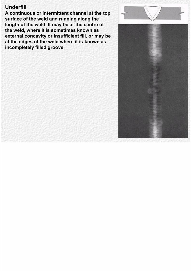
UnderfillA continuous or intermittent channel at the top
8/10/2019 Defects Welding
http://slidepdf.com/reader/full/defects-welding 88/206
p
surface of the weld and running along the
length of the weld. It may be at the centre of
the weld, where it is sometimes known as
external concavity or insufficient fill, or may beat the edges of the weld where it is known as
incompletely filled groove.
UnderfillA continuous or intermittent

8/10/2019 Defects Welding
http://slidepdf.com/reader/full/defects-welding 89/206
channel at the top surface of the
weld and running along the length
of the weld. It may be at the centre
of the weld, where it is sometimesknown as external concavity or
insufficient fill, or may be at the
edges of the weld where it is
known as incompletely filled
groove.
UnderfillA continuous or intermittent

8/10/2019 Defects Welding
http://slidepdf.com/reader/full/defects-welding 90/206
channel at the top surface of the
weld and running along the length
of the weld. It may be at the centre
of the weld, where it is sometimesknown as external concavity or
insufficient fill, or may be at the
edges of the weld where it is known
as incompletely filled groove.
UnderfillA continuous or intermittent

8/10/2019 Defects Welding
http://slidepdf.com/reader/full/defects-welding 91/206
channel at the top surface of the
weld and running along the
length of the weld. It may be at
the centre of the weld, where it issometimes known as external
concavity or insufficient fill, or
may be at the edges of the weld
where it is known as incompletely
filled groove.
UndercutAn irregular groove at the top edge (toe) of a

8/10/2019 Defects Welding
http://slidepdf.com/reader/full/defects-welding 92/206
weld caused by contraction of the weld
metal, or by burning away (gouging) of the
parent metal. Appears as a dark irregular
band along the top edge of the weld metal.Undercut can also occur at the root of the
weld, although this can easily be confused
with lack of root fusion.
In this case the thickness of one (or both)
of the sheets is reduced at the toe of the
weld. This is due to incorrect settings /
procedure. There is already a stress
concentration at the toe of the weld and
any undercut will reduce the strength of the
join.

8/10/2019 Defects Welding
http://slidepdf.com/reader/full/defects-welding 93/206
Incomplete root penetration (LP)
Failure of the weld metal to extend
i t th t f j i t A

8/10/2019 Defects Welding
http://slidepdf.com/reader/full/defects-welding 94/206
into the root area of a joint. Appears
as a dark continuous or intermittent
band with mostly straight edges. In
close square butt joints it may appearas a continuous or broken line. There
is often a line of fine porosity
associated with this defect.

8/10/2019 Defects Welding
http://slidepdf.com/reader/full/defects-welding 95/206
Incomplete root penetration
(LP)
F il f th ld t l t

8/10/2019 Defects Welding
http://slidepdf.com/reader/full/defects-welding 96/206
Failure of the weld metal to
extend into the root area of a joint.
Appears as a dark continuous or
intermittent band with mostlystraight edges. In close square
butt joints it may appear as a
continuous or broken line. There
is often a line of fine porosity
associated with this defect.

8/10/2019 Defects Welding
http://slidepdf.com/reader/full/defects-welding 97/206
Root concavitySometimes called suck-back. A
h ll i th t f b tt

8/10/2019 Defects Welding
http://slidepdf.com/reader/full/defects-welding 98/206
shallow groove in the root of a butt
weld. Appears as a dark area along the
centre of the weld.
Welding Defects

8/10/2019 Defects Welding
http://slidepdf.com/reader/full/defects-welding 99/206
Lack of inter-run fusion (LI)
A lack of union between adjacent weld runs in a
multi run weld It appears as a faint dark line with

8/10/2019 Defects Welding
http://slidepdf.com/reader/full/defects-welding 100/206
multi-run weld. It appears as a faint dark line with
sharply defined edges.
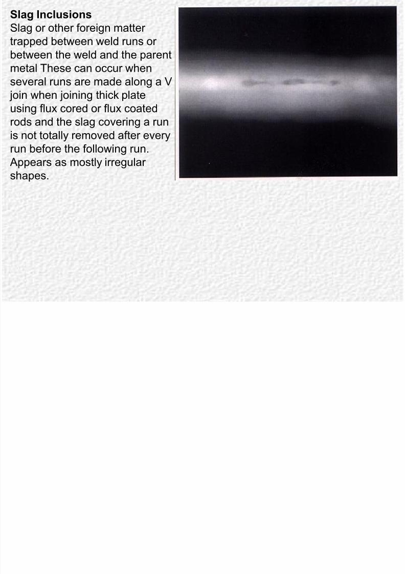
Slag Inclusions
Slag or other foreign matter trapped
b t ld b t th ld

8/10/2019 Defects Welding
http://slidepdf.com/reader/full/defects-welding 101/206
between weld runs or between the weld
and the parent metal These can occur
when several runs are made along a V join
when joining thick plate using flux cored orflux coated rods and the slag covering a run
is not totally removed after every run before
the following run. Appears as mostly
irregular shapes.
Slag Inclusions
Slag or other foreign matter
t d b t ld
8/10/2019 Defects Welding
http://slidepdf.com/reader/full/defects-welding 102/206
trapped between weld runs or
between the weld and the parent
metal These can occur when
several runs are made along a V join when joining thick plate
using flux cored or flux coated
rods and the slag covering a run
is not totally removed after every
run before the following run. Appears as mostly irregular
shapes.
Slag Inclusions
Slag or other foreign matter trapped
b t ld b t th ld

8/10/2019 Defects Welding
http://slidepdf.com/reader/full/defects-welding 103/206
between weld runs or between the weld
and the parent metal These can occur
when several runs are made along a V join
when joining thick plate using flux cored orflux coated rods and the slag covering a run
is not totally removed after every run before
the following run. Appears as mostly
irregular shapes.
Inclusion (IN)
Slag or other foreign matter
trapped between weld runds or

8/10/2019 Defects Welding
http://slidepdf.com/reader/full/defects-welding 104/206
trapped between weld runds or
between the weld and the parent
metal. Appears as mostly irregular
shapes.
Inclusion (IN)
Slag or other foreign matter
trapped between weld runs or

8/10/2019 Defects Welding
http://slidepdf.com/reader/full/defects-welding 105/206
trapped between weld runs or
between the weld and the parent
metal. Appears as mostly irregular
shapes.

8/10/2019 Defects Welding
http://slidepdf.com/reader/full/defects-welding 106/206
Slag Inclusion
pieces of slag on the surface of a finished weld. These slags may get
entrapped during welding.
Linear inclusion
Also known as a slag line. Caused by lines
of slag trapped generally between the weld

8/10/2019 Defects Welding
http://slidepdf.com/reader/full/defects-welding 107/206
of slag trapped, generally between the weld
metal and parent metal, in a multi-run weld.
Appears as one or more dark bands, mostly
with irregular edges, running along a weld.
Lack of side wall fusion
A lack of union between the weld metal and
the parent metal at the side of a weld Its

8/10/2019 Defects Welding
http://slidepdf.com/reader/full/defects-welding 108/206
the parent metal at the side of a weld. Its
image appears as a straight dark line or
band, depending on the orientation of the
beam of radiation. Its detection depends onits orientation relative to the beam
orientation, and sometimes requires an
additional exposure with the beam aligned
parallel to the weld preparation face.

8/10/2019 Defects Welding
http://slidepdf.com/reader/full/defects-welding 109/206
Lack of fusion

8/10/2019 Defects Welding
http://slidepdf.com/reader/full/defects-welding 110/206
Lack of fusion

8/10/2019 Defects Welding
http://slidepdf.com/reader/full/defects-welding 111/206

8/10/2019 Defects Welding
http://slidepdf.com/reader/full/defects-welding 112/206
Lack of fusion

8/10/2019 Defects Welding
http://slidepdf.com/reader/full/defects-welding 113/206
Lack of fusion
Lack of root fusion
A lack of union of the weld metal with the
parent metal at the root of a weld Lack of

8/10/2019 Defects Welding
http://slidepdf.com/reader/full/defects-welding 114/206
parent metal at the root of a weld. Lack of
fusion results from too little heat input and /
or too rapid traverse of the welding torch (gas
or electric). Appears as a straight line or bandat one or both edges of the weld root image.
Cracking
This can occur due just to thermal shrinkage or due to a combination of
strain accompanying phase change and thermal shrinkage

8/10/2019 Defects Welding
http://slidepdf.com/reader/full/defects-welding 115/206
strain accompanying phase change and thermal shrinkage.
In the case of welded stiff frames, a combination of poor design and
inappropriate procedure may result in high residual stresses and cracking.
Where alloy steels or steels with a carbon content greater than about 0.2%are being welded, self cooling may be rapid enough to cause some (brittle)
martensite to form. This will easily develop cracks.
To prevent these problems a process of pre-heating in stages may be
needed and after welding a slow controlled post cooling in stages will be
required. This can greatly increase the cost of welded joins, but for highstrength steels, such as those used in petrochemical plant and piping, there
may well be no alternative.
Longitudinal Cracks Cracks appear a fine dark lines, mostly jagged
edges, sometimes discontinuous. Its detection

8/10/2019 Defects Welding
http://slidepdf.com/reader/full/defects-welding 116/206
edges, sometimes discontinuous. Its detection
is dependent on its orientation relative to the
radiation beam.
Longitudinal Cracks Cracks appear a fine dark lines,
mostly jagged edges, sometimes

8/10/2019 Defects Welding
http://slidepdf.com/reader/full/defects-welding 117/206
y j gg g ,
discontinuous. Its detection is
dependent on its orientation relative
to the radiation beam.
Longitudinal Cracks Cracks appear a fine dark lines,
mostly jagged edges, sometimes

8/10/2019 Defects Welding
http://slidepdf.com/reader/full/defects-welding 118/206
y j gg g ,
discontinuous. Its detection is
dependent on its orientation
relative to the radiation beam.
Longitudinal Cracks Cracks appear a fine dark lines,
mostly jagged edges, sometimes

8/10/2019 Defects Welding
http://slidepdf.com/reader/full/defects-welding 119/206
y j gg g ,
discontinuous. Its detection is
dependent on its orientation relative
to the radiation beam.
Longitudinal Cracks Cracks appear a fine dark lines,
mostly jagged edges, sometimes

8/10/2019 Defects Welding
http://slidepdf.com/reader/full/defects-welding 120/206
y j gg g ,
discontinuous. Its detection is
dependent on its orientation
relative to the radiation beam.
Longitudinal Cracks Cracks appear a fine dark lines,
mostly jagged edges, sometimes

8/10/2019 Defects Welding
http://slidepdf.com/reader/full/defects-welding 121/206
y j gg g
discontinuous. Its detection is
dependent on its orientation
relative to the radiation beam.
Longitudinal Cracks Cracks appear a fine dark lines,
mostly jagged edges,

8/10/2019 Defects Welding
http://slidepdf.com/reader/full/defects-welding 122/206
sometimes discontinuous. Its
detection is dependent on its
orientation relative to theradiation beam.
Longitudinal Cracks Cracks appear a fine dark
lines, mostly jagged edges,

8/10/2019 Defects Welding
http://slidepdf.com/reader/full/defects-welding 123/206
sometimes discontinuous. Its
detection is dependent on its
orientation relative to theradiation beam.
Longitudinal root crack
This form of crack occurs mostly in the
parent metal adjacent to the root run of the

8/10/2019 Defects Welding
http://slidepdf.com/reader/full/defects-welding 124/206
p j
weld. It appears as a fine dark line, mostly
jagged edges, sometimes discontinuous. Its
detection is dependent on its orientationrelative to the radiation beam.
Linear misalignment
may have a linear indication associated
with it caused by the protruding edge of

8/10/2019 Defects Welding
http://slidepdf.com/reader/full/defects-welding 125/206
y p g g
one of the plates. This has the
appearance of a lack of penetration
indication.
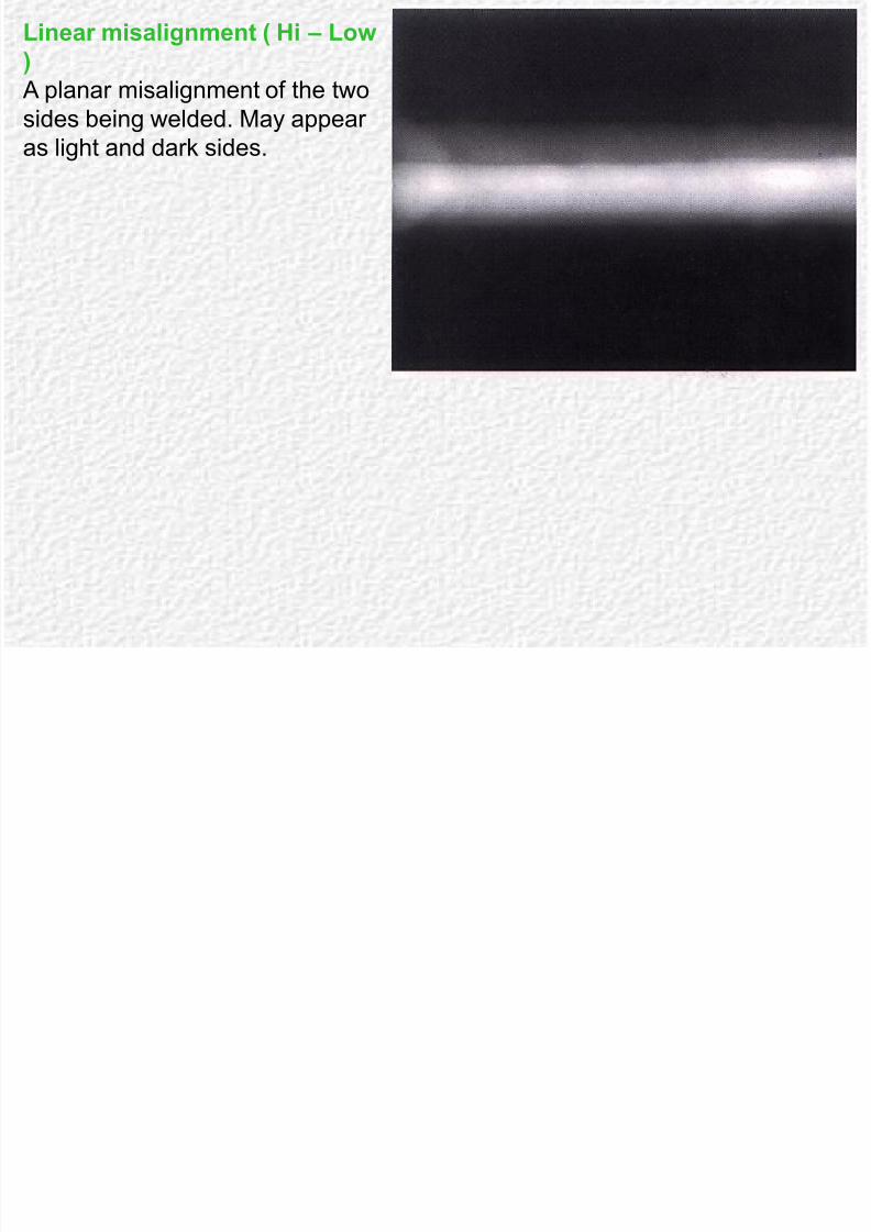
Linear misalignment ( Hi – Low )
A planar misalignment of the two sides
being welded. May appear as light and

8/10/2019 Defects Welding
http://slidepdf.com/reader/full/defects-welding 126/206
g y pp g
dark sides.
Linear misalignment ( Hi – Low)
A planar misalignment of the two

8/10/2019 Defects Welding
http://slidepdf.com/reader/full/defects-welding 127/206
p g
sides being welded. May appear
as light and dark sides.
Linear misalignment ( Hi – Low)
A planar misalignment of the two
8/10/2019 Defects Welding
http://slidepdf.com/reader/full/defects-welding 128/206
p g
sides being welded. May appear
as light and dark sides.

8/10/2019 Defects Welding
http://slidepdf.com/reader/full/defects-welding 129/206
Linear misalignment ( Hi – Low)
A planar misalignment of the two

8/10/2019 Defects Welding
http://slidepdf.com/reader/full/defects-welding 130/206
sides being welded. May appear
as light and dark sides.
Linear porosity A line of mostly small round images aligned
along a weld. Note that this can sometimes

8/10/2019 Defects Welding
http://slidepdf.com/reader/full/defects-welding 131/206
indicate a lack of fusion defect which may
not be immediately obvious.
PorosityThis occurs when gases are trapped in the
solidifying weld metal. These may arise

8/10/2019 Defects Welding
http://slidepdf.com/reader/full/defects-welding 132/206
from damp consumables or metal or, from
dirt, particularly oil or grease, on the metal
in the vicinity of the weld. This can beavoided by ensuring all consumables are
stored in dry conditions and work is
carefully cleaned and degreased prior to
welding. Porosities are mostly spherical gas
hole in the weld metal. Appears as one ormore circular dark images.
Transverse Crack A transverse crack runs across the weld
bead and sometimes into the parent metal.

8/10/2019 Defects Welding
http://slidepdf.com/reader/full/defects-welding 133/206
It appears as a fine dark line, mostly jagged
edges, sometimes discontinuous. Its
detection is dependent on its orientationrelative to the radiation beam.
Transverse Crack A transverse crack runs across
the weld bead and sometimes

8/10/2019 Defects Welding
http://slidepdf.com/reader/full/defects-welding 134/206
into the parent metal. It appears
as a fine dark line, mostly
jagged edges, sometimesdiscontinuous. Its detection is
dependent on its orientation
relative to the radiation beam.
Tungsten inclusion An inclusion of tungsten from a tungsten
electrode used in the gas tungsten arc

8/10/2019 Defects Welding
http://slidepdf.com/reader/full/defects-welding 135/206
(GTAW) process. Appears as small white
sharp edged images in the weld metal due to
the fact that tungsten is much denser thansteel or aluminium.
Tungsten inclusion An inclusion of tungsten from a tungsten
electrode used in the gas tungsten arc

8/10/2019 Defects Welding
http://slidepdf.com/reader/full/defects-welding 136/206
(GTAW) process. Appears as small
white sharp edged images in the weld
metal due to the fact that tungsten ismuch denser than steel or aluminium.
Tungsten inclusion An inclusion of tungsten from a tungsten
electrode used in the gas tungsten arc
(GTAW) A ll hi

8/10/2019 Defects Welding
http://slidepdf.com/reader/full/defects-welding 137/206
(GTAW) process. Appears as small white
sharp edged images in the weld metal
due to the fact that tungsten is muchdenser than steel or aluminium.
An inclusion of aluminiumoxide in a arc welding
process. Appears as small
hit i l i i th

8/10/2019 Defects Welding
http://slidepdf.com/reader/full/defects-welding 138/206
white irregular images in the
weld metal due to the fact
that oxide is much denserthan steel or aluminium.

8/10/2019 Defects Welding
http://slidepdf.com/reader/full/defects-welding 139/206

8/10/2019 Defects Welding
http://slidepdf.com/reader/full/defects-welding 140/206
Welding Defects

8/10/2019 Defects Welding
http://slidepdf.com/reader/full/defects-welding 141/206

8/10/2019 Defects Welding
http://slidepdf.com/reader/full/defects-welding 142/206

8/10/2019 Defects Welding
http://slidepdf.com/reader/full/defects-welding 143/206
Welding spatters

8/10/2019 Defects Welding
http://slidepdf.com/reader/full/defects-welding 144/206
Welding spatters

8/10/2019 Defects Welding
http://slidepdf.com/reader/full/defects-welding 145/206
Film radiography
8/10/2019 Defects Welding
http://slidepdf.com/reader/full/defects-welding 146/206
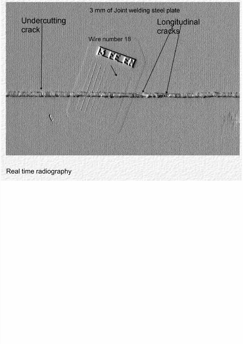
Real time radiography
vii

8/10/2019 Defects Welding
http://slidepdf.com/reader/full/defects-welding 147/206
8/10/2019 Defects Welding
http://slidepdf.com/reader/full/defects-welding 148/206
PorosityThis occurs as a series of fine cavities, generally spherical, but sometimes
tubular in form (worm holes). Porosity can occur in various patterns, for
example linear porosity scattered porosity and start porosity The defect is

8/10/2019 Defects Welding
http://slidepdf.com/reader/full/defects-welding 149/206
example, linear porosity, scattered porosity and start porosity. The defect is
caused by such factors as:
Excessive gas content generated by chemical reactions in the weld.Gases or other hydrocarbon contamination.
Damp flux.
Porosity in weld
The preferred NDT techniques are radiography, ultrasonic testing and, if the
porosity is at the surface, liquid penetrants.
Trapped slag A number of welding processes deliberately form a flux or slag covering
over the molten weld pool as it solidifies. This isolates the weld metal from
the atmosphere and helps purify the weld metal Some of this slag can be

8/10/2019 Defects Welding
http://slidepdf.com/reader/full/defects-welding 150/206
the atmosphere and helps purify the weld metal. Some of this slag can be
trapped in the weld metal due to insufficient slag removal between runs or
insufficient back gouging of the root. Depending on the circumstances offormation the slag is generally in an isolated or linear pattern. Slag can be
classed as a „volume‟ defect.
Slag entrapment in weld
Preferred NDT technique for detecting trapped slag is radiography or
ultrasonic testing.
Lack of fusionThis refers to incomplete fusion between the weld metal and the parent
metal or weld metal with previously deposited weld metal. Three distinct
types of fusion defect occur depending on the location of the defect within

8/10/2019 Defects Welding
http://slidepdf.com/reader/full/defects-welding 151/206
types of fusion defect occur depending on the location of the defect within
the weld zone:
Lack of side wall fusion.Lack of inter-run fusion, that is, between weld runs.
Lack of root fusion.
Lack of fusion defects
Causes include such factors as:
Poor welding technique.Incorrect electrode size.
Inadequate weld preparation.
Lack of fusion defects are generally planar and crack-like in nature. The
best NDT method is ultrasonic testing. Radiography may be used for lack of
side wall and root fusion.
Lack of penetrationThis is where the weld metal has failed to penetrate into the root of a joint as
opposed to lack of root fusion where weld metal has penetrated into the root
area but has failed to fuse to one side

8/10/2019 Defects Welding
http://slidepdf.com/reader/full/defects-welding 152/206
area but has failed to fuse to one side.
The causes of lack of penetration are the same as for lack of fusion defects.
Lack of penetrationThe preferred NDT technique for detecting lack of penetration is
radiography or ultrasonic testing.
Hot crackingThis is also called solidification cracking because it occurs when the weld
metal has just solidified and so is in a weakened condition. Most weld metal
cracks are of this type for example centreline cracking as shown below

8/10/2019 Defects Welding
http://slidepdf.com/reader/full/defects-welding 153/206
cracks are of this type, for example, centreline cracking, as shown below,
and crater cracks.
Centreline crackingHot cracks result from the combined action of stress and lack of ductility of
the weld metal at high temperatures. Contributing factors are:
restraint
weld chemistry (for example, high sulphur content)
weld shape, (for example, concave fillet welds).Preferred NDT techniques for detecting hot cracking is magnetic particle
testing or liquid penetrant testing.
Heat affected zone (HAZ) cracksThese are also called underbead cracks or toe cracks.
The heat affect zone, HAZ, of a weld is that part of the parent metal
adjacent to the weld fusion line where the metal has been heated to a

8/10/2019 Defects Welding
http://slidepdf.com/reader/full/defects-welding 154/206
adjacent to the weld fusion line where the metal has been heated to a
sufficiently high temperature by the weld to alter its grain structure.
Underbead cracks occur in the weld HAZ and lie parallel to the fusion linewhile toe cracks commence at the weld toe and angle across the HAZ as
shown below. HAZ cracks form at temperatures around room temperature
and may form shortly after welding or take hours or even days to form.
Forms of HAZ cracking in welds
The cracks occur under the combined action of:Hydrogen in the HAZ – hydrogen can originate, for example, from using
damp electrodes.
Weld restraint – that is, stress.
A hard HAZ – this relates to parent metal chemistry and cooling rate after
welding.
The tendency to cracking is influenced by:
The type of steel used (it is favoured by higher carbon and alloy steels).
Material thickness.
Type of joints.
Type of welding process.
The best NDT techni ue for underbead cracks is ultrasonic testin while

8/10/2019 Defects Welding
http://slidepdf.com/reader/full/defects-welding 155/206
Other Types of DefectsSome other types of defects include:
Quench cracks
Grinding cracks
8/10/2019 Defects Welding
http://slidepdf.com/reader/full/defects-welding 156/206
Fatigue cracks
Stress corrosion cracks
Quench cracksThese cracks develop in the later stages of the quenching operation of a „quench
and temper‟ heat treatment on steel. Quenching involves heating the steel to about
850°C and cooling rapidly in a water or oil bath. Quench cracks result where the
residual surface stresses produced in the quenching exceed the tensile strength of
the steel.
Quench cracks characteristically run from the surface in a straight line towards the
centre as shown below. They tend to occur at points of stress concentration such as
section changes, sharp corners, etc.
Contributory factors to formation include:
Too severe a quenching medium for the steel-section combination.
Quenching steel out cold.
Delay between quenching and tempering.
Quench cracks in steel bar
The preferred NDT technique for detecting quench cracks is magnetic particle
testing.
Other Types of DefectsSome other types of defects include:
Quench cracks
Grinding cracks

8/10/2019 Defects Welding
http://slidepdf.com/reader/full/defects-welding 157/206
Fatigue cracks
Stress corrosion cracks
Quench cracksThese cracks develop in the later stages of the quenching operation of a „quench
and temper‟ heat treatment on steel. Quenching involves heating the steel to about
850°C and cooling rapidly in a water or oil bath. Quench cracks result where the
residual surface stresses produced in the quenching exceed the tensile strength of
the steel.
Quench cracks characteristically run from the surface in a straight line towards the
centre as shown below. They tend to occur at points of stress concentration such as
section changes, sharp corners, etc.
Contributory factors to formation include:
Too severe a quenching medium for the steel-section combination.
Quenching steel out cold.
Delay between quenching and tempering.
Quench cracks in steel bar
The preferred NDT technique for detecting quench cracks is magnetic particle
testing.

8/10/2019 Defects Welding
http://slidepdf.com/reader/full/defects-welding 158/206
Fatigue cracksFatigue cracks represent a major area of application in maintenance NDT.
Fatigue occurs under the repeated application of a stress which is insufficient to
cause failure when applied statically. It accounts for 80% to 90% of the fractures of
h i l t

8/10/2019 Defects Welding
http://slidepdf.com/reader/full/defects-welding 159/206
mechanical components.
The fatigue process involves a slowly progressing crack over an extended time
period and fatigue cracks almost always start at the surface. This makes themideally suited to detection by NDT techniques. The great bulk of fatigue cracks start
at points of stress concentration such as sharp corners, thread roots, keyways, oil
holes and so on.
The preferred NDT techniques are magnetic particle testing for steel components
and liquid penetrant testing for non-ferrous metals. Ultrasonic testing may be used
for in situ inspection of assemblies.
Stress corrosion crackingLike fatigue cracking, stress corrosion cracking is a
service-generated defect.
Stress corrosion is the corrosion of a metal
l t d b t Th d t i ti d th

8/10/2019 Defects Welding
http://slidepdf.com/reader/full/defects-welding 160/206
accelerated by stress. The deterioration under these
conditions is much more harmful than the separate
effects of stress and corrosion. For a given metal,stress corrosion only occurs in certain environments
peculiar to that metal.
Some classic combinations are:
Brass in mercury or ammonia compounds – „season
cracking‟.
Steel in sodium hydroxide – „caustic embrittlement‟.
Austenitic stainless steel in chlorides.
Stress corrosion cracking commonly takes the form of
a multitude of branched inter-granular cracks with little
or no corrosive attack to the surface as shown below. It
is not normally visually detectable.
Stress corrosion cracks
The best NDT technique for detecting stress corrosion
cracks in ferromagnetic metals is magnetic particle
testing. For other metals liquid penetrant testing is
used.

8/10/2019 Defects Welding
http://slidepdf.com/reader/full/defects-welding 161/206
Stress corrosion cracking

8/10/2019 Defects Welding
http://slidepdf.com/reader/full/defects-welding 162/206

8/10/2019 Defects Welding
http://slidepdf.com/reader/full/defects-welding 163/206
Corrosion pitting and wall thinning

8/10/2019 Defects Welding
http://slidepdf.com/reader/full/defects-welding 164/206
Cracks

8/10/2019 Defects Welding
http://slidepdf.com/reader/full/defects-welding 165/206
AdvantagesSimple and easy to conduct
Will detect surface and near surface flaws
Can detect flaws filled with contaminants e.g. oxide or non metallic inclusions
Sensitivity of testing can be specified and checked

8/10/2019 Defects Welding
http://slidepdf.com/reader/full/defects-welding 166/206
Sensitivity of testing can be specified and checked
Disadvantages
Can only be applied to ferromagnetic materialsWill not detect deep internal flaws
High currents applied to component may cause damage
Components usually have to be demagnetised
Lack of PenetrationLack of penetration results
from the failure of the weld
metal to fully penetrate the root
section resulting in a surface

8/10/2019 Defects Welding
http://slidepdf.com/reader/full/defects-welding 167/206
section, resulting in a surface
connected area of incompletely
welded material. Generallypresents as a strong corner
reflector detectable from both
sides of the weld.
Lack of Root FusionLack of root fusion results from the failure of the weld metal to fully fuse with the root
area of the weld. Lack of root fusion may occur in areas of full penetration. Generally
presents as a strong corner reflector detectable from only one side of the weld.

8/10/2019 Defects Welding
http://slidepdf.com/reader/full/defects-welding 168/206
Root undercutSlight melting of the parent metal at the toe of a weld resulting in an irregular shallow
groove at the edge of the weld. Generally presents with variable amplitude as a
slightly ragged corner reflector at the edge of the weld.
Root undercut

8/10/2019 Defects Welding
http://slidepdf.com/reader/full/defects-welding 169/206
Root undercut
Roll your mouse over the red numbered bullet to read the label.
Scanning the root area should be carried out with a line scan using a steep probeangle.
Orbital scanThe probe is positioned for maximum reflection from the discontinuity, and the
screen height adjusted to around 80% FSH. The probe is then moved in an orbital
movement around the discontinuity, trying to keep the discontinuity at the centre of
the orbit This type of scan may be impractical if the surface contour does not permit

8/10/2019 Defects Welding
http://slidepdf.com/reader/full/defects-welding 170/206
the orbit. This type of scan may be impractical if the surface contour does not permit
the free movement of the probe.
Shrinkcastings

8/10/2019 Defects Welding
http://slidepdf.com/reader/full/defects-welding 171/206
Sandinclu
castings

8/10/2019 Defects Welding
http://slidepdf.com/reader/full/defects-welding 172/206

8/10/2019 Defects Welding
http://slidepdf.com/reader/full/defects-welding 173/206
The end
thank you
8/10/2019 Defects Welding
http://slidepdf.com/reader/full/defects-welding 174/206

8/10/2019 Defects Welding
http://slidepdf.com/reader/full/defects-welding 175/206

8/10/2019 Defects Welding
http://slidepdf.com/reader/full/defects-welding 176/206
Double sided (including tee butt) weld testing, where the welding and inspection canbe undertaken from both sides. This is generally the simpler case, and is the subject
of this section.
Single sided weld testing, where the welding and inspection access is from one side
only. This is more complex than the double sided weld testing, and will be discussed

8/10/2019 Defects Welding
http://slidepdf.com/reader/full/defects-welding 177/206
y p g,
in the next task.
Double sided (including tee butt) weld testing, where the welding and inspection canbe undertaken from both sides. This is generally the simpler case, and is the subject
of this section.
Single sided weld testing, where the welding and inspection access is from one side
only. This is more complex than the double sided weld testing, and will be discussed
8/10/2019 Defects Welding
http://slidepdf.com/reader/full/defects-welding 178/206
y p g,
in the next task.
CracksCracks are discontinuities caused by fracture under stress. They can occur at high
or low temperatures
Cold Cracks: occur when due to embrittlement the solid weld metal cannot withstand
the contraction stresses. Embrittlement is often due to retained hydrogen and

8/10/2019 Defects Welding
http://slidepdf.com/reader/full/defects-welding 179/206
y g
excessive hardness caused by rapid cooling. Cold cracks may be delayed in their
formation.Underbead Cracks, Toe Cracks: are a variation of cold cracks, which occur in the
HAZ due to the presence of hydrogen and excessive hardness from rapid cooling of
higher carbon and alloy steels.
Hot Cracks: occur as the metal cools from liquid to solid and cannot withstand the
solidification stresses. Hot cracking is more likely to occur when the weld deposit is
deep and narrow, such as the weld root area. The most common type is thecentreline crack. It rarely occurs in flat capping passes
Lamellar Tears: are cracking in the HAZ of welds where nonmetallic inclusions are
oriented across the shrinkage stresses, just beneath the surface – especially in
heavy section tee butt welds. This type of cracking was common, but is now less
common due to improved steelmaking practice.
Chevron Cracks: are small transverse cracks that can occur in submerged arc
welding of heavy sections, 50 mm and thicker.
Entrapped gases (porosity, wormholes)Entrapped gases are a result of gases held in the liquid weld metal. The gases
separate (precipitate) when the metal cools and solidifies to form gas filled cavities.
Porosity can occur as clusters of porosity (more common with improperly used low
hydrogen electrodes), or as single pores. Porosity of this type is due to shortcomings

8/10/2019 Defects Welding
http://slidepdf.com/reader/full/defects-welding 180/206
y g ) g p y yp g
in the shielding process.
Wormholes occur when the weld metal interacts with surface contaminant such asoils, or a cavity (such as a lamination or partial tack weld) containing gas, and the
resulting pocket of gas expands under the heat of welding, to be entrapped in the
weld metal. These wormholes generally have a tadpole-like shape with the tail of the
tadpole pointing to the likely source of the gas.

8/10/2019 Defects Welding
http://slidepdf.com/reader/full/defects-welding 181/206
Inclusions (slag inclusions, wagon tracks)Inclusions are the result of incomplete cleaning of one pass before the following
pass is made.
It is sometimes difficult to distinguish between inclusions and lack of fusion.
Inclusions are generally regarded as „Volumetric‟ (three-dimensional) while lack of

8/10/2019 Defects Welding
http://slidepdf.com/reader/full/defects-welding 182/206
fusion is regarded as „planar‟ (two-dimensional). The two discontinuity types may
occur together. Penetration discontinuities
Penetration discontinuities occur where the weld metal does not penetrate its
intended extent. Lack of penetration generally appears as a vertical planar
discontinuity at the weld root.
Shape and profile
The weld is required to have an acceptable shape both for its intended service andto make it testable. It is not generally the role of the ultrasonic technician to make
judgment on the shape of the weld, but if the weld has poor shape, it can obstruct
ultrasonic interpretation.
Undercut is a sharp groove that sometimes occurs at the weld toe (the edge of the
weld cap).
Shrinkage cavities (shrinkage grooves)
Shrinkage grooves occur when the weld deposit solidifies and there is not enough
molten metal to compensate for the volume reduction. Shrinkage grooves are rare in
double V welds, but may occur more frequently in single V welds.
Some basic guidelines for detection of discontinuities:Try and strike all discontinuities as close to square as possible.
Study the weld preparation for orientation of the fusion face
Try and select an angle of incidence within 10° of the fusion faces.

8/10/2019 Defects Welding
http://slidepdf.com/reader/full/defects-welding 183/206
This may mean using a number of probe angles and scanning surfaces for
effective scanningIf this is impossible, some extra gain will assist. We will see how codes and
standards deal with this problem.
Use lower frequencies for initial detection.
Although higher frequencies will be better for measurement and evaluation, you
may miss discontinuities. You will never get the chance to evaluate if you donot find them first!
Strange as it may sound, for planar reflectors at unfavourable incidence, the
larger the reflector, the lower the probability of detection.
Use the largest practical transducer diameter, as this will give greater effective
coverage per scan.
The Ultrasonic Flaw Detector (UFD) provides an electrical signal to the probe.The probe converts the electrical signal to a pulse of mechanical vibration.
The couplant allows transmission of the mechanical vibration into the test piece.
The compression wave travels across the sample.
The backwall reflects the compression wave back to the probe.
8/10/2019 Defects Welding
http://slidepdf.com/reader/full/defects-welding 184/206
The discontinuity (if present) reflects the compression wave back to the probe.
The amplitude of the discontinuity signal reaches its maximum when thediscontinuity area is equal to the beam width.
The probe reconverts the received compression wave back to an electrical signal.
The UFD display shows the transit time (X axis) versus signal amplitude (Y axis) in
real time.
The horizontal location of the reflected signal on the UFD screen is proportional to
the time for the ultrasound to travel from the probe to the discontinuity and back.The amplitude of the discontinuity signal is proportional to the area of the reflecting
surface - if the discontinuity is smaller than the beam, and reflection conditions
are ideal.
The UFD contains the essential elements to control and interpret the test that
include:
a timer to control the pulse ratea pulse generator to energise the probe
a sweep generator to drive the display
an amplifier for the weak signals returned by the probe
a screen (digital or analogue) to display the signals from the probe
electrical connections to the probe.

8/10/2019 Defects Welding
http://slidepdf.com/reader/full/defects-welding 185/206
Lamb waves are a mode of propagation produced in thin materialsLamb waves may be produced in thicknesses below three times the wavelength,
where shear waves cannot exist. There are a number of variants of Lamb waves,
and their application is limited to thin materials. Lamb waves are also known as
plate waves.

8/10/2019 Defects Welding
http://slidepdf.com/reader/full/defects-welding 186/206

8/10/2019 Defects Welding
http://slidepdf.com/reader/full/defects-welding 187/206
Corner ReflectorsIn optics, corners act as almost perfect reflectors of light.
Corner reflector
This property is very useful in manufacturing reflectors for the rear of cars and „cats
eyes‟ for road markers. If you have ever seen two mirrors set at right angles, you

8/10/2019 Defects Welding
http://slidepdf.com/reader/full/defects-welding 188/206
will notice that no matter where you are, you receive a perfect reflection of your
own image as the incident beam is reflected back along its own path. Two otherthings are also evident when you look at your image in a corner mirror:
With one mirror, the image is laterally inverted, and your left hand looks like your
right hand, but with a corner mirror the image is right way round.
With a corner mirror, the reflection is often darker because it has undergone two
reflections, and lost more light.
Corner reflection relies on reflection at two complimentary anglesUnfortunately with ultrasonics, the reflection from a corner is not quite so simple,
because every corner reflection involves two reflections at complimentary angles.
(Complimentary angles are two angles that add up to 90°.)
If, for example we strike a corner at 60°, it will require a reflection at 60° and 30° to
produce the return reflection. You will remember from our discussion of oblique
incidence and the demonstration we looked at to calculate the angles and soundpressure, that the 60° reflection will be 100% with no mode conversion, but the
30° reflection will only be a 13% reflection of the shear mode. It will also produce
a significant compression mode at an angle of 67°. For these reasons, corners
can be very deceptive reflectors – very easy to manage in some situations and
very difficult at other times

8/10/2019 Defects Welding
http://slidepdf.com/reader/full/defects-welding 189/206

8/10/2019 Defects Welding
http://slidepdf.com/reader/full/defects-welding 190/206

8/10/2019 Defects Welding
http://slidepdf.com/reader/full/defects-welding 191/206

8/10/2019 Defects Welding
http://slidepdf.com/reader/full/defects-welding 192/206

8/10/2019 Defects Welding
http://slidepdf.com/reader/full/defects-welding 193/206

8/10/2019 Defects Welding
http://slidepdf.com/reader/full/defects-welding 194/206

8/10/2019 Defects Welding
http://slidepdf.com/reader/full/defects-welding 195/206

8/10/2019 Defects Welding
http://slidepdf.com/reader/full/defects-welding 196/206

8/10/2019 Defects Welding
http://slidepdf.com/reader/full/defects-welding 197/206

8/10/2019 Defects Welding
http://slidepdf.com/reader/full/defects-welding 198/206

8/10/2019 Defects Welding
http://slidepdf.com/reader/full/defects-welding 199/206

8/10/2019 Defects Welding
http://slidepdf.com/reader/full/defects-welding 200/206

8/10/2019 Defects Welding
http://slidepdf.com/reader/full/defects-welding 201/206

8/10/2019 Defects Welding
http://slidepdf.com/reader/full/defects-welding 202/206

8/10/2019 Defects Welding
http://slidepdf.com/reader/full/defects-welding 203/206

8/10/2019 Defects Welding
http://slidepdf.com/reader/full/defects-welding 204/206

8/10/2019 Defects Welding
http://slidepdf.com/reader/full/defects-welding 205/206

8/10/2019 Defects Welding
http://slidepdf.com/reader/full/defects-welding 206/206