Embed Size (px)
Citation preview

PS40 Programming & Operation Manual
Revision: 1.1 (3/03/00) PS40 Frn: 3.10
IPSO USA 99 Aberdeen Loop Panama City, FL 32405 1-800-USA-IPSO

- 1-2 -

- 1-3 -
CONTENTS Section Page
1 PROGRAMING .................................................................................................... 1-4 1.1 Overview Of Modes .................................................................................................................... 1-4 1.2 Operating Mode ........................................................................................................................... 1-5
1.2.1 Select And Run A Program .......................................................................................................... 1-5 1.2.2 Program Progress Indicators........................................................................................................ 1-5 1.2.3 Program Start Delay..................................................................................................................... 1-5 1.2.4 Changing To Another Program..................................................................................................... 1-5 1.2.5 Temporary Program Alteration ..................................................................................................... 1-6 1.2.6 Temperature and RPM Display .................................................................................................... 1-6 1.2.7 Rapid Advance ............................................................................................................................ 1-6 1.2.8 Programmed stop ........................................................................................................................ 1-6 1.2.9 Stopping A Program..................................................................................................................... 1-6 1.2.10 Manually Adding Water ................................................................................................................ 1-7 1.2.11 Manually Draining ........................................................................................................................ 1-7 1.2.12 Manual Heating............................................................................................................................ 1-7 1.2.13 Manually Activating The Chemical Supply Signals........................................................................ 1-7 1.2.14 Display Total Operating Hours ..................................................................................................... 1-7 1.2.15 Program Memory Inventory.......................................................................................................... 1-8
1.3 Programming Mode.................................................................................................................... 1-8 1.3.1 Creating a Program...................................................................................................................... 1-8 1.3.2 Inserting / Deleting a Program step ............................................................................................ 1-14
1.4 Copy Mode .................................................................................................................................. 1-15 1.5 Setup (Pre-Program) Mode .................................................................................................... 1-15 1.6 Test Mode .................................................................................................................................... 1-20
1.6.1 Test 1: Inputs ............................................................................................................................. 1-21 1.6.2 Test 2: Analog Reference.......................................................................................................... 1-21 1.6.3 Test 4: Water level control test .................................................................................................. 1-22 1.6.4 Test 5: Temperature sensor test................................................................................................ 1-22 1.6.5 Test 6: Test of the outputs......................................................................................................... 1-22 1.6.6 Test 7: Keyboard test ................................................................................................................ 1-23 1.6.7 Ram reset .................................................................................................................................. 1-23 1.6.8 PS40 Water level sensor Calibration Procedure ......................................................................... 1-23
1.7 PS40 Diagnostics...................................................................................................................... 1-24 1.7.1 Alarm Codes.............................................................................................................................. 1-24 1.7.2 Fault Codes ............................................................................................................................... 1-25
1.8 Programming Tips .................................................................................................................... 1-25
2 PROGRAMMING WORKSHEETS ............................. 2-26

- 1-4 -
1 PROGRAMING 1.1 Overview Of Modes For more detailed instructions on these “Modes” please see the corresponding sections following in this manual. Self Test Mode When the machine is powered up the computer will proceed through a self-test and will show ProM.3.10 and then Good.3.10. temporarily on the display . The last three digits of each indicate the software version. Then “dAtA.XXXX” appears temporarily. This number will change each time a program is installed or modified. If all is good, the display will then change to “StArt” indicating that the machine is in operating mode and is ready to run.
Operating Mode This is the mode in which the machine is normally operated. In order to access and run an existing program enter
the programs number on the keypad, and then press to start the machine.
Note: If this is the first time that the PS40 has been powered up and it has not been set up, “a3” will appear on the display. Press “Enter” to make it go away and proceed to the “Setup (Pre-Program) Mode” section. Programming Mode This mode is used in order to install new programs or to alter previously installed programs. In order to access the programming mode insure that “StArt” is on the display, turn the programming key to “Program”, and very quickly press “ 455” on the keypad. If “Prog 05” appears, you did not press the keys quickly enough.
Press to abort and repeat the process and start over. If “ProGr” appears on the display (flashing) you are in the programming mode. Note: If the Programming key is not turned to “Program” when this is attempted, A0 will appear on the display indicating that program mode has been locked out. Copying Mode This function is utilized in order to copy entire programs and assign them new program numbers. This feature saves a lot of time and effort when creating similar programs with few changes. In order to access the Copy mode insure that StArt is on the display and turn the programming key to “Program”. Very quickly press “
328” on the key pad. If “Prog 08” appears you did not press the keys quickly enough. Press to abort and repeat the process and start over. If “CoPY PrG” appears on the display you are in the Copy mode. Note: If the Programming key is not turned to “Program” when this is attempted, A0 will appear on the display indicating that copy mode has been locked out.
Setup (Pre-program) Mode Note: Do not modify any of the PS40’s setup items unless you understand what you are doing – some settings can make the machine appear to be malfunctioning. Although all IPH machines are
- 1-5 -
preconfigured at the factory, some special features like chemical timer hold or temperature units (C or F) may need to be enabled or changed for a particular installation. In order to access the Setup (pre-program) mode, insure that “StArt” is on the display, turn the programming key to “Program”, and very quickly press “ 619” on the touch pad. If “Prog 09” appears, you did not press
the keys quickly enough. Press to abort and repeat the process. If “ProGrAM” appears, you are in the Preprogramming /Configuration function or mode. Press and “PrE” will appear on the display. You can now
scroll through the configuration using the key and altar as needed using the key.
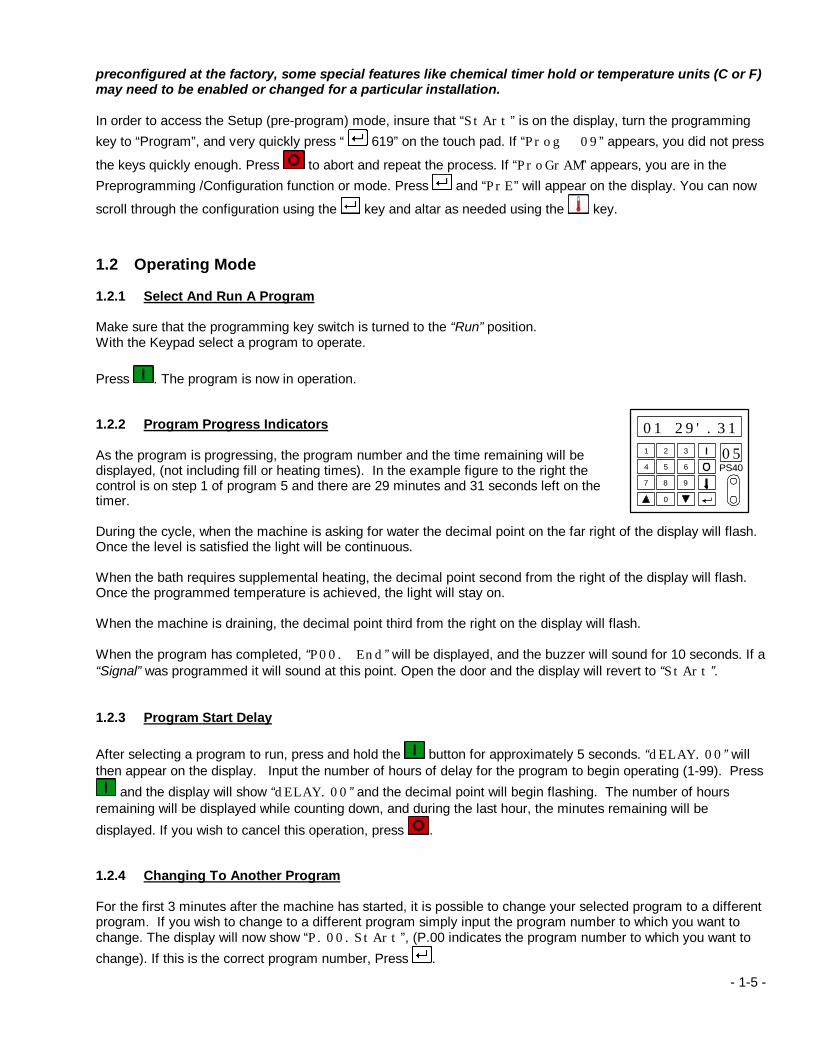
1.2 Operating Mode 1.2.1 Select And Run A Program Make sure that the programming key switch is turned to the “Run” position. With the Keypad select a program to operate. Press . The program is now in operation. 1.2.2 Program Progress Indicators As the program is progressing, the program number and the time remaining will be displayed, (not including fill or heating times). In the example figure to the right the control is on step 1 of program 5 and there are 29 minutes and 31 seconds left on the timer. During the cycle, when the machine is asking for water the decimal point on the far right of the display will flash. Once the level is satisfied the light will be continuous. When the bath requires supplemental heating, the decimal point second from the right of the display will flash. Once the programmed temperature is achieved, the light will stay on. When the machine is draining, the decimal point third from the right on the display will flash. When the program has completed, “P00. End” will be displayed, and the buzzer will sound for 10 seconds. If a “Signal” was programmed it will sound at this point. Open the door and the display will revert to “StArt”. 1.2.3 Program Start Delay
After selecting a program to run, press and hold the button for approximately 5 seconds. “dELAY.00” will then appear on the display. Input the number of hours of delay for the program to begin operating (1-99). Press
and the display will show “dELAY.00” and the decimal point will begin flashing. The number of hours remaining will be displayed while counting down, and during the last hour, the minutes remaining will be
displayed. If you wish to cancel this operation, press . 1.2.4 Changing To Another Program For the first 3 minutes after the machine has started, it is possible to change your selected program to a different program. If you wish to change to a different program simply input the program number to which you want to change. The display will now show “P.00.StArt”, (P.00 indicates the program number to which you want to change). If this is the correct program number, Press .
1 32
4 65
7 98
0
PS40
01 29'.3105
- 1-6 -
1.2.5 Temporary Program Alteration
Select a program number. Before starting the program, press and hold the button. While holding the button in, press . Scroll through each program step using the button and make the desired changes. When finished, press to begin the program. The program will now run with the temporary alterations. 1.2.6 Temperature and RPM Display
By pressing the button on the touch pad one time while the program is in operation the current bath temperature will be displayed.
Press the button again and the programmed temperature of the bath will be displayed momentarily.
Press the button again and the highest programmed temperature of the program will be displayed momentarily.
Press the button again and the cylinder speed will be displayed momentarily.
By pressing and holding the button for 3 seconds during any of the above, the display will remain at that
function until is pressed again. 1.2.7 Rapid Advance By pushing and holding the button on the touch pad the program can be rapid advanced through each program step. The rapid advance will stop at each drain and the button must be released and pressed again in order to continue with the rapid advance sequence. The “ACCL” feature is selected as an option during the setup (pre-program) process and can be disabled if desired. 1.2.8 Programmed stop If an indefinite time stop (0 minutes) was programmed the program will pause and wait for the operator to restart the program. The water will stay in the machine and all cylinder movement will cease. The display will show “StoP”. The program will not continue until the button is pressed. If a programmed time stop was programmed (1-999 minutes) the display will alternate between “StoPtiME” and
the remainder of the programmed stop time. The time stop can also be interrupted by pressing the button. Note: If a signal has been programmed, it will sound at the beginning of the “Programmed Stop Time”. If a stop was programmed during the “final Spin / Extract” the program will automatically resume after 20 minutes. 1.2.9 Stopping A Program
To terminate a program, press the button on the touch pad. After 5 seconds the machine will drain the water and “oPEn door” will appear on the display after approximately 30 seconds. Open the door and “CloSE” will
- 1-7 -
appear on the display. Close the door, and the display will display will flash the program and time information
where it was stopped. Press again the display will show “End”. Open the door and the display will return to “StArt”. The “EnEr” feature is selected as an option during the setup (pre-program) process and can be disabled if desired. 1.2.10 Manually Adding Water After the program has been running for 3 minutes, you can add more water to the machine by first pressing and releasing button number 1, then pressing and holding buttons “1-9” on the touch pad. After releasing the button, the water will shut off, and the water level will be displayed for 3 seconds. These buttons correspond to the water inlet valves. 1. Cup 1 2. Cup 2 (optional) 3. Cup 3 (optional) 4. Cup 4 (optional) 5. Cup 5 (optional) 6. Cup 6 (not used on IPH machines) 7. Cold water inlet 8. Hot water inlet 9. Chemical flush For machines equipped with water reuse inlet valves you can access these by first pressing and releasing button number 2, then pressing the button on the keypad that corresponds with the desired reuse water inlet valve ( 1 = water reuse valve number 1, etc.). 1.2.11 Manually Draining After the program has been running for 3 minutes you can drain the water by pressing the “0” button on the keypad, then pressing the corresponding drain valve number on the keypad (1 = Drain valve number 1, 2 = Drain valve number 2, etc.). The water level will be displayed while pressing these buttons, so you can drain back down to a desired level. 1.2.12 Manual Heating After the program has been running for 3 minutes you can activate the heating system by pressing and holding the 4 button on the touch pad (if the machine is equipped with an optional electrical or steam heating system). While the button is pressed, the temperature will be shown on the display and the supplemental heating system will be activated until the button is released. 1.2.13 Manually Activating The Chemical Supply Signals After the program has been running for 3 minutes, you can activate liquid supply outputs “1-12” by first pressing and releasing the “3” button on the touch pad, and then pressing the corresponding number on the keypad for the desired liquid supply output. Hold the button in for the desired output length, then release. 1.2.14 Display Total Operating Hours Before the machine has been started quickly press “ 223” and the total hours that the machine has been run will be displayed for 5 seconds.

- 1-8 -
1.2.15 Program Memory Inventory Before the machine has been started quickly press “ 788” and the display will show the first program in the machine and the total number of steps in that program. Example: “Prg01.08” Means program 1 contains 8 steps. After 1 second, the next program in the machine will be displayed and so forth. After the last program in the machine is displayed, the total number of free program steps will be displayed. Press and the display will return to “StArt”.
1.3 Programming Mode In order to access the programming mode insure that “StArt” is on the display. Turn the programming key to
“Program” and very quickly press “ 455” on the keypad. If “Prog 05” appears, you did not press the keys
quickly enough. Press to abort and repeat the process and start over. If “ProG” appears on the display (flashing) you are in the Programming mode. Note: If the Programming key is not turned to “Program” when this is attempted, A0 will flash
on the display. 1.3.1 Creating a Program ProG (flashing) Entering the Programming mode. Press ProG 00 Enter the program number that you wish to program or modify. Press 00id 00 The first “00” indicates the Program number selected, and the “id 00” indicates the program
step, or bath, i.e., “02id 01” indicates program 2, step number 1. A program step, or bath, is a part of a wash program (prewash, main wash, rinse etc.) and always ends with a drain or extract. Put in the program step number to be programmed. Press .
00. Cyt. Cycle or program step time, not including fill, drain or extract time. (No user input required).
Press . t 00.00 Input the desired wash time for this step, in minutes and seconds. Press . 00.rotE Cylinder action and pause times. (Dwell) (No user input required). Press . AG.Force Wash action type desired. If you want to use a wash action other than what was preset in the
setup (pre-program) process as the default, press . If you would like to use the default wash
actions preset in the Setup (pre-program) process, press . The display will now show AG.norMAL
- 1-9 -
A 12.0 Input the number of seconds that you want the cylinder to rotate before pausing to reverse direction. Press
S 03.0 Input the number of seconds that you want the cylinder to pause before turning in the opposite
direction. Press SP 42 Input the desired wash speed in RPM. Press .
00.tENP Temperature of this program step, or bath. (No user input required). Press . `F 000 Input the temperature desired for this program step or bath. If no temperature control is desired
for this bath, select 033. This will allow you to specify which Main fill valves are to open. Press .
Note: The next step will be determined by the “HEAt-SYS” option chosen in the setup (pre-
program) mode. If “HEAt-nod” was chosen in the setup (pre-program), you be allowed to select from:
• “HEAt” (Supplemental heating without Temperature controlled water inlets). If this option is
chosen pressing transfers you to “no HECo” or “00. SE-i”. Pressing transfers you to “nod”.
• “nod” (Temperature controlled water inlets without Supplemental heating). Pressing
transfers you to “00. SE-i”. Pressing transfers you “HEAt-nod”.
• “HEAt-Nod” (Temperature controlled water inlets with Supplemental heating). Pressing
transfers you to “no HECo” or “00. SE-i”. Pressing transfers you back to “HEAt”
If “HEAt” was chosen during Preprogramming or configuration, the display will automatically go to “no HECo” or “00. SE-i”.
If “nod” was chosen during Preprogramming or Configuration, the display will automatically go to “XX. SE-i”.
no HECo If “HECo” is selected, the program will stop until the programmed temperature is reached. Press
to alter your selection. Press .
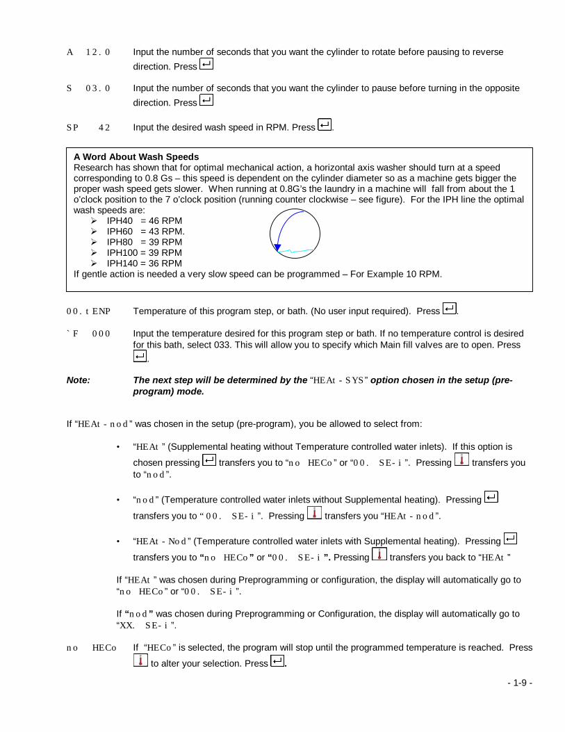
A Word About Wash Speeds Research has shown that for optimal mechanical action, a horizontal axis washer should turn at a speed corresponding to 0.8 Gs – this speed is dependent on the cylinder diameter so as a machine gets bigger the proper wash speed gets slower. When running at 0.8G’s the laundry in a machine will fall from about the 1 o’clock position to the 7 o’clock position (running counter clockwise – see figure). For the IPH line the optimal wash speeds are: Ø IPH40 = 46 RPM Ø IPH60 = 43 RPM. Ø IPH80 = 39 RPM Ø IPH100 = 39 RPM Ø IPH140 = 36 RPM
If gentle action is needed a very slow speed can be programmed – For Example 10 RPM.
- 1-10 -
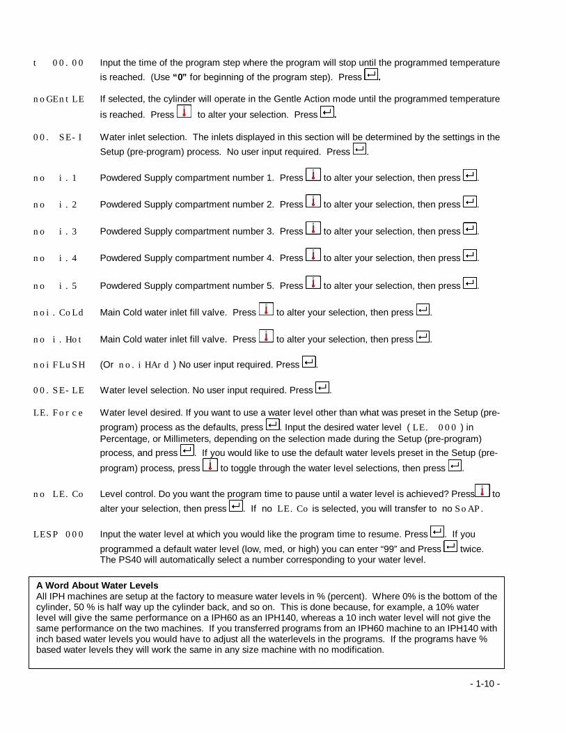
t 00.00 Input the time of the program step where the program will stop until the programmed temperature
is reached. (Use “0” for beginning of the program step). Press . noGEntLE If selected, the cylinder will operate in the Gentle Action mode until the programmed temperature
is reached. Press to alter your selection. Press . 00. SE-I Water inlet selection. The inlets displayed in this section will be determined by the settings in the
Setup (pre-program) process. No user input required. Press .
no i.1 Powdered Supply compartment number 1. Press to alter your selection, then press .
no i.2 Powdered Supply compartment number 2. Press to alter your selection, then press .
no i.3 Powdered Supply compartment number 3. Press to alter your selection, then press .
no i.4 Powdered Supply compartment number 4. Press to alter your selection, then press . no i.5 Powdered Supply compartment number 5. Press to alter your selection, then press .
noi.CoLd Main Cold water inlet fill valve. Press to alter your selection, then press .
no i.Hot Main Cold water inlet fill valve. Press to alter your selection, then press . noiFLuSH (Or no.iHArd ) No user input required. Press . 00.SE-LE Water level selection. No user input required. Press . LE.Force Water level desired. If you want to use a water level other than what was preset in the Setup (pre-
program) process as the defaults, press . Input the desired water level ( LE. 000 ) in Percentage, or Millimeters, depending on the selection made during the Setup (pre-program) process, and press . If you would like to use the default water levels preset in the Setup (pre-
program) process, press to toggle through the water level selections, then press .
no LE.Co Level control. Do you want the program time to pause until a water level is achieved? Press to alter your selection, then press . If no LE.Co is selected, you will transfer to no SoAP.
LESP 000 Input the water level at which you would like the program time to resume. Press . If you
programmed a default water level (low, med, or high) you can enter “99” and Press twice. The PS40 will automatically select a number corresponding to your water level.
A Word About Water Levels All IPH machines are setup at the factory to measure water levels in % (percent). Where 0% is the bottom of the cylinder, 50 % is half way up the cylinder back, and so on. This is done because, for example, a 10% water level will give the same performance on a IPH60 as an IPH140, whereas a 10 inch water level will not give the same performance on the two machines. If you transferred programs from an IPH60 machine to an IPH140 with inch based water levels you would have to adjust all the waterlevels in the programs. If the programs have % based water levels they will work the same in any size machine with no modification.

- 1-11 -
.Note: The next step will be determined by the “ SoAP” option chosen during the setup (pre-
program) process.
If “no SoAP” was chosen, you will automatically transfer to “no Add” If “ SoAP” was chosen, you will transfer to “SoAP” (or “no SoAP”)
no SoAP Would you like to utilize 1 or more Liquid supply outputs during this step? Press to alter your selection, then press . If “no SoAP” was chosen, you will automatically transfer to “no Add”
Note: The number of Liquid supply outputs available will be determined by the equipment
options chosen during the Setup (pre-program) process.
no So1 Liquid supply output signal number 1. Use to alter your selection. Press . If no So1 was selected you will transfer to the next available Liquid supply output.
t1. 000 Input the number of seconds that you would like this liquid supply signal. Press .
no So2 Liquid supply output signal number 2. Use to alter your selection. Press . If no So2 was selected you will transfer to the next available Liquid supply output.
t2. 000 Input the number of seconds that you would like this liquid supply signal. Press .
no So3 Liquid supply output signal number 3. Use to alter your selection. Press . If no So3 was selected you will transfer to the next available Liquid supply output.
t3. 000 Input the number of seconds that you would like this liquid supply signal. Press .
no So4 Liquid supply output signal number 4. Use to alter your selection. Press . If no So4 was selected you will transfer to the next available Liquid supply output.
t4. 000 Input the number of seconds that you would like this liquid supply signal. Press .
no So5 Liquid supply output signal number 5. Use to alter your selection. Press . If no So5 was selected you will transfer to the next available Liquid supply output.
t5. 000 Input the number of seconds that you would like this liquid supply signal. Press .
no So6 Liquid supply output signal number 6. Use to alter your selection. Press . If no So6 was selected you will transfer to the next available Liquid supply output.
t6. 000 Input the number of seconds that you would like this liquid supply signal. Press .
no So7 Liquid supply output signal number 7. Use to alter your selection. Press . If no So7 was selected you will transfer to the next available Liquid supply output.
T7. 000 Input the number of seconds that you would like this liquid supply signal. Press .

- 1-12 -
no So8 Liquid supply output signal number 8. Use to alter your selection. Press . If no So8 was selected you will transfer to the next available Liquid supply output.
T8. 000 Input the number of seconds that you would like this liquid supply signal. Press .
no So9 Liquid supply output signal number 9. Use to alter your selection. Press . If no So9 was selected you will transfer to the next available Liquid supply output.
T9. 000 Input the number of seconds that you would like this liquid supply signal. Press .
no So10 Liquid supply output signal number 10. Use to alter your selection. Press . If no So10 was selected you will transfer to the next available Liquid supply output.
T10.000 Input the number of seconds that you would like this liquid supply signal. Press .
no So11 Liquid supply output signal number 11. Use to alter your selection. Press . If no So11 was selected you will transfer to the next available Liquid supply output.
T11.000 Input the number of seconds that you would like this liquid supply signal. Press .
no So12 Liquid supply output signal number 12. Use to alter your selection. Press . If no So12 was selected you will transfer to the next available Liquid supply output.
T12.000 Input the number of seconds that you would like this liquid supply signal. Press . no Add Choose the “Add” option if you would like to insert a cool down cycle, program stop cycle, or
Soak in this program step. Use to alter your selection. Press .
Cool Do you want to insert a cool down cycle in this program step? Use to alter your selection. Press .
Cdu\.000 If yes, input the highest cool down temperature desired in first increment. Press . Cdu. 000 Input the lowest cool down temperature desired in the first increment. Press . Cdn\.000 If yes, input the highest cool down temperature desired in last increment. Press . Cdn. 000 Input the lowest cool down temperature desired in the last increment. Press .
StoP Would you like to insert a program “stop” in this step? Use to alter your selection. Press . StoP.000 If yes, input the number of minutes (up to 999) that you want the program to stop. Press . If
SiGnAL was selected during the Setup (pre-program) process you will transfer to SiGnA000
SoAH Would you like to program a “Soak” cycle during this step” Use to alter your selection. Press
. SoAH.000 If yes, input the number of minutes (up to 999) that you would like the soak cycle to last.
- 1-13 -
Press . If SiGnAL was selected during the Setup (pre-program) process you will transfer to SiGnA000
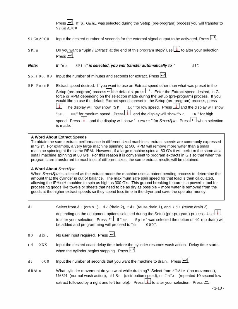
SiGnA000 Input the desired number of seconds for the external signal output to be activated. Press .
SPin Do you want a “Spin / Extract” at the end of this program step? Use to alter your selection. Press .
Note: If “no SPin” is selected, you will transfer automatically to “ d1”. Spit00.00 Input the number of minutes and seconds for extract. Press . SP.ForcE Extract speed desired. If you want to use an Extract speed other than what was preset in the
Setup (pre-program) process as the defaults, press . Enter the Extract speed desired, in G-force or RPM depending on the selection made during the Setup (pre-program) process. If you would like to use the default Extract speeds preset in the Setup (pre-program) process, press
. The display will now show “SP. Lo” for low speed. Press and the display will show
“SP. NE” for medium speed. Press and the display will show “SP. Hi” for high
speed. Press and the display will show “ smart” for SmartSpin. Press when selection is made.
d1 Select from d1 (drain 1), d2 (drain 2), rd1 (reuse drain 1), and rd2 (reuse drain 2)
depending on the equipment options selected during the Setup (pre-program) process. Use to alter your selection. Press . If “ no Spin” was selected the option of d0 (no drain) will be added and programming will proceed to “dt 000”.
00. dEt. No user input required. Press . td XXX Input the desired coast delay time before the cylinder resumes wash action. Delay time starts
when the cylinder begins stopping. Press . dt 000 Input the number of seconds that you want the machine to drain. Press . dRAin What cylinder movement do you want while draining? Select from dRAin ( no movement),
UASH (normal wash action), diSt (distribution speed), or JoLt (repeated 10 second low
extract followed by a right and left tumble). Press to alter your selection. Press .
A Word About Extract Speeds To obtain the same extract performance in different sized machines, extract speeds are commonly expressed in “G’s”. For example, a very large machine spinning at 500 RPM will remove more water than a small machine spinning at the same RPM. However, if a large machine spins at 80 G’s it will perform the same as a small machine spinning at 80 G’s. For this reason it is convenient to program extracts in G’s so that when the programs are transferred to machines of different sizes, the same extract results will be obtained. A Word About SmartSpin When SmartSpin is selected as the extract mode the machine uses a patent pending process to determine the amount that the cylinder is out of balance. The maximum safe spin speed for that load is then calculated, allowing the IPHxxH machine to spin as high as 300 G’s. This ground breaking feature is a powerful tool for processing goods like towels or sheets that need to be as dry as possible – more water is removed from the goods at the higher extract speeds so they spend less time in the dryer and save the operator money.

- 1-14 -
t=00.00 Display of total time for this program step (plus fill and heating). No user input required. Press
. FrEE 000 Free area left in RAM available for programming. No user input required. Press . End Are you through programming this formula? If you would like to program another step in this
formula select “no End”. Use to alter your selection. Press . Note: If “no End” is selected you will transfer automatically to “00.id 00” (the last two
zeros would be the next step number in the program). tu 000 Tumble (Shakeout). Input the number of seconds that you would like the cylinder to tumble in
wash speed before ending the program and unlocking the loading door. Press . If SiGnAL was selected during the Setup (pre-program) process you will transfer to SiGnA000
SiGnA000 Input the desired number of seconds for the external signal output to be activated (if the feature
was enabled in the setup (pre-program) process. Press . The display will now read “dAtA.0000” and then change to “StArt”, exiting program mode. 1.3.2 Inserting / Deleting a Program step In order to Insert or Delete a program step, you must first enter the “Program Mode”. In order to access the Programming mode, insure that “StArt” is on the display, turn the programming key to
“Program”, and very quickly press “ 455” on the key pad. If “Prog 05” appears, you did not press the keys
quickly enough. Press to abort and repeat the process. If “ProGr” appears on the display (flashing) you are in the Programming mode. Note: If the Programming key is not turned to “Program” when this is attempted, “A0” will flash on the display. ProG Entering the Programming mode. Press . ProG 00 Enter the program number that you wish to program or modify. Press . To insert a step 00.id 00 Enter the “Program Step” where you would like to insert a “New Program Step”. Press . Now
Press .
00 inS Press . A new program step has been inserted. Example: 03.id 04
Enter the “Program Step” where you would like to insert a “New Program Step”. Press (you have selected program number 3, step number 4).
Press . “04 inS” appears on the display.
Press . A new program step has been inserted in the place of program step number 4, and the old program step number 4 has been moved to program step number 5.

- 1-15 -
To delete a step
00.id 00 Enter the “Program Step” that you would like to delete. Press . Now Press . 00 dEL Press . The program step has been deleted. Example: 03.id 04
Enter the “Program Step” where you would like to delete a “Program Step”. Press . (you have selected program number 3, step number 4).
Press . “04 dEL” appears on the display.
Press . Program step number 4 has been deleted, and program step number 5 has been moved into its place.
1.4 Copy Mode In order to access the Copy mode insure that StArt is on the display and turn the programming key to “Program”. Very quickly press “ 328” on the key pad. If “Prog 08” appears you did not press the keys
quickly enough. Press to abort and repeat the process and start over. If “CoPY PrG” appears on the display you are in the Copy mode. Note: If the Programming key is not turned to “Program” when this is attempted, A0 will appear on the display indicating that copy mode has been locked out. Copy Prg Press . Source.00 Enter the two-digit source program number – this is the program number that you want to make a
copy of. Press . Dest .00 Enter the two digit destination program number – this is the program number you want to store
the copy in. Press . 01....02 The PS40 will display the “source . . . .destination” program numbers to confirm the operation.
Press to complete the operation or to abort the operation. Example: To copy program 41 to program 5 you would do the following enter copy mode as explained
above. Source.00 Enter the source program number which is 41 on the key pad. Source.41 Press . Dest .00 Enter the destination program number which is 05 on the key pad. Dest .05 Press . 41....05 Press to confirm the operation. Start The display will return to the start prompt. The program has been copied.
1.5 Setup (Pre-Program) Mode In order to access the Setup (pre-program) mode, insure that “StArt” is on the display, turn the programming key to “Program”, and very quickly press “ 619” on the touch pad. If “Prog 09” appears, you did not press
the keys quickly enough. Press to abort and repeat the process and start over. If “ProGrAM” appears, you are in the Setup (pre-program) mode. Press and “PrE” will appear on the display.
- 1-16 -
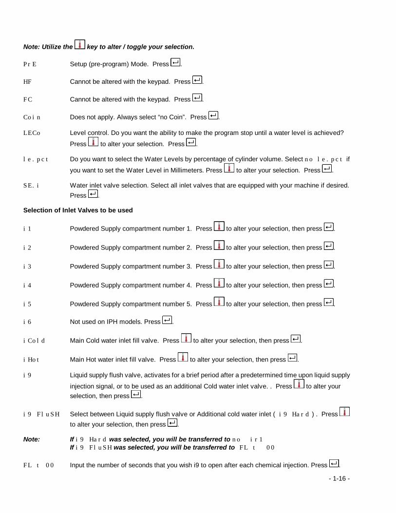
Note: Utilize the key to alter / toggle your selection. PrE Setup (pre-program) Mode. Press . HF Cannot be altered with the keypad. Press . FC Cannot be altered with the keypad. Press . Coin Does not apply. Always select “no Coin”. Press . LECo Level control. Do you want the ability to make the program stop until a water level is achieved?
Press to alter your selection. Press . le.pct Do you want to select the Water Levels by percentage of cylinder volume. Select no le.pct if
you want to set the Water Level in Millimeters. Press to alter your selection. Press . SE.i Water inlet valve selection. Select all inlet valves that are equipped with your machine if desired.
Press . Selection of Inlet Valves to be used
i1 Powdered Supply compartment number 1. Press to alter your selection, then press .
i2 Powdered Supply compartment number 2. Press to alter your selection, then press .
i3 Powdered Supply compartment number 3. Press to alter your selection, then press .
i4 Powdered Supply compartment number 4. Press to alter your selection, then press .
i5 Powdered Supply compartment number 5. Press to alter your selection, then press . i6 Not used on IPH models. Press .
iCold Main Cold water inlet fill valve. Press to alter your selection, then press .
iHot Main Hot water inlet fill valve. Press to alter your selection, then press . i9 Liquid supply flush valve, activates for a brief period after a predetermined time upon liquid supply
injection signal, or to be used as an additional Cold water inlet valve. . Press to alter your selection, then press .
i9 FluSH Select between Liquid supply flush valve or Additional cold water inlet ( i9 Hard ) . Press to alter your selection, then press .
Note: If i9 Hard was selected, you will be transferred to no ir1 If i9 FluSH was selected, you will be transferred to FL t 00 FL t 00 Input the number of seconds that you wish i9 to open after each chemical injection. Press .
- 1-17 -
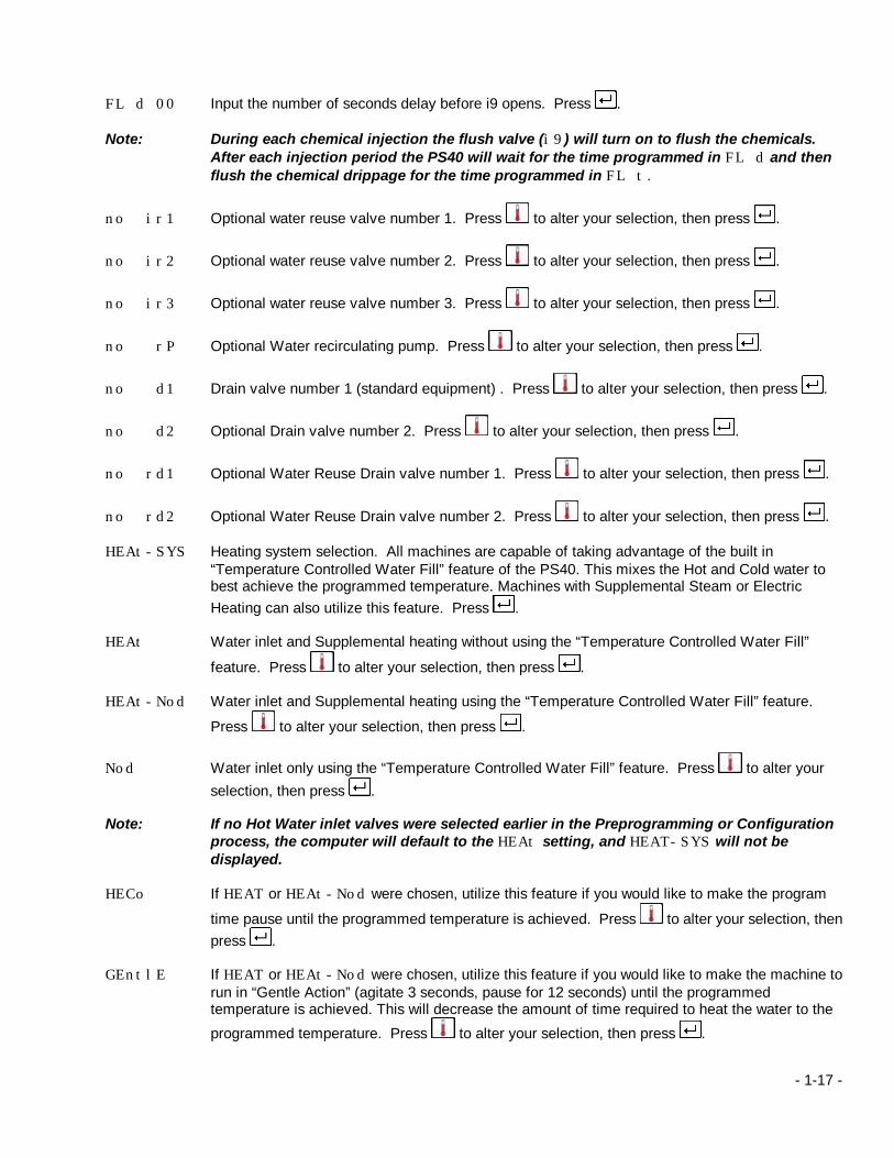
FL d 00 Input the number of seconds delay before i9 opens. Press . Note: During each chemical injection the flush valve (i9) will turn on to flush the chemicals.
After each injection period the PS40 will wait for the time programmed in FL d and then flush the chemical drippage for the time programmed in FL t.
no ir1 Optional water reuse valve number 1. Press to alter your selection, then press .
no ir2 Optional water reuse valve number 2. Press to alter your selection, then press .
no ir3 Optional water reuse valve number 3. Press to alter your selection, then press .
no rP Optional Water recirculating pump. Press to alter your selection, then press .
no d1 Drain valve number 1 (standard equipment) . Press to alter your selection, then press .
no d2 Optional Drain valve number 2. Press to alter your selection, then press .
no rd1 Optional Water Reuse Drain valve number 1. Press to alter your selection, then press .
no rd2 Optional Water Reuse Drain valve number 2. Press to alter your selection, then press . HEAt-SYS Heating system selection. All machines are capable of taking advantage of the built in
“Temperature Controlled Water Fill” feature of the PS40. This mixes the Hot and Cold water to best achieve the programmed temperature. Machines with Supplemental Steam or Electric Heating can also utilize this feature. Press .
HEAt Water inlet and Supplemental heating without using the “Temperature Controlled Water Fill”
feature. Press to alter your selection, then press . HEAt-Nod Water inlet and Supplemental heating using the “Temperature Controlled Water Fill” feature.
Press to alter your selection, then press .
Nod Water inlet only using the “Temperature Controlled Water Fill” feature. Press to alter your selection, then press .
Note: If no Hot Water inlet valves were selected earlier in the Preprogramming or Configuration
process, the computer will default to the HEAt setting, and HEAT-SYS will not be displayed.
HECo If HEAT or HEAt-Nod were chosen, utilize this feature if you would like to make the program
time pause until the programmed temperature is achieved. Press to alter your selection, then press .
GEntlE If HEAT or HEAt-Nod were chosen, utilize this feature if you would like to make the machine to
run in “Gentle Action” (agitate 3 seconds, pause for 12 seconds) until the programmed temperature is achieved. This will decrease the amount of time required to heat the water to the
programmed temperature. Press to alter your selection, then press .

- 1-18 -
Note: If Nod was selected, HECo and GentlE will not be displayed.
t *C Do you want the Temperature displayed as Celsius or Fahrenheit? Press to alter your selection, then press .
SoAP Do you want to program Liquid Supply outputs?. Press to alter your selection, then press .
Note: If no SoAP was selected you will transfer to Add
SoAP. 1 Do you want to be able to program Liquid supply output number 1? Press to alter your selection, then press .
SoAP. 2 Do you want to be able to program Liquid supply output number 2? Press to alter your selection, then press .
SoAP. 3 Do you want to be able to program Liquid supply output number 3? Press to alter your selection, then press .
SoAP. 4 Do you want to be able to program Liquid supply output number 4? Press to alter your selection, then press .
SoAP. 5 Do you want to be able to program Liquid supply output number 5? Press to alter your selection, then press .
SoAP. 6 Do you want to be able to program Liquid supply output number 6? Press to alter your selection, then press .
no.5,GnAL Do you want to dedicate Liquid supply output number 6 to activate an external signaling device
rather than using it for a liquid supply output? Press to alter your selection, then press .
SoAP. 7 Do you want to be able to program Liquid supply output number 7? Press to alter your selection, then press .
SoAP. 8 Do you want to be able to program Optional Liquid supply output number 8 if the machine is so
equipped? Press to alter your selection, then press . SoAP. 9 Do you want to be able to program Optional Liquid supply output number 9 if the machine is so
equipped? Press to alter your selection, then press . SoAP. 10 Do you want to be able to program Optional Liquid supply output number 10 if the machine is so
equipped? Press to alter your selection, then press . SoAP. 11 Do you want to be able to program Optional Liquid supply output number 11 if the machine is so
equipped? Press to alter your selection, then press . SoAP. 12 Do you want to be able to program Optional Liquid supply output number 12 if the machine is so
equipped? Press to alter your selection, then press .
- 1-19 -
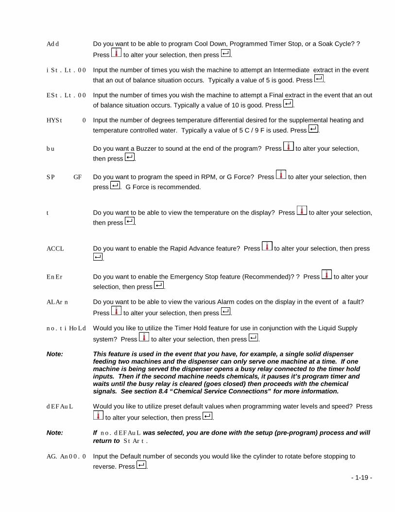
Add Do you want to be able to program Cool Down, Programmed Timer Stop, or a Soak Cycle? ?
Press to alter your selection, then press . iSt.Lt.00 Input the number of times you wish the machine to attempt an Intermediate extract in the event
that an out of balance situation occurs. Typically a value of 5 is good. Press . ESt.Lt.00 Input the number of times you wish the machine to attempt a Final extract in the event that an out
of balance situation occurs. Typically a value of 10 is good. Press . HYSt 0 Input the number of degrees temperature differential desired for the supplemental heating and
temperature controlled water. Typically a value of 5 C / 9 F is used. Press .
bu Do you want a Buzzer to sound at the end of the program? Press to alter your selection, then press .
SP GF Do you want to program the speed in RPM, or G Force? Press to alter your selection, then press . G Force is recommended.
t Do you want to be able to view the temperature on the display? Press to alter your selection, then press .
ACCL Do you want to enable the Rapid Advance feature? Press to alter your selection, then press .
EnEr Do you want to enable the Emergency Stop feature (Recommended)? ? Press to alter your selection, then press .
ALArn Do you want to be able to view the various Alarm codes on the display in the event of a fault?
Press to alter your selection, then press . no.tiHoLd Would you like to utilize the Timer Hold feature for use in conjunction with the Liquid Supply
system? Press to alter your selection, then press . Note: This feature is used in the event that you have, for example, a single solid dispenser
feeding two machines and the dispenser can only serve one machine at a time. If one machine is being served the dispenser opens a busy relay connected to the timer hold inputs. Then if the second machine needs chemicals, it pauses it’s program timer and waits until the busy relay is cleared (goes closed) then proceeds with the chemical signals. See section 8.4 “Chemical Service Connections” for more information.
dEFAuL Would you like to utilize preset default values when programming water levels and speed? Press
to alter your selection, then press . Note: If no.dEFAuL was selected, you are done with the setup (pre-program) process and will
return to StArt. AG.An00.0 Input the Default number of seconds you would like the cylinder to rotate before stopping to
reverse. Press .
- 1-20 -
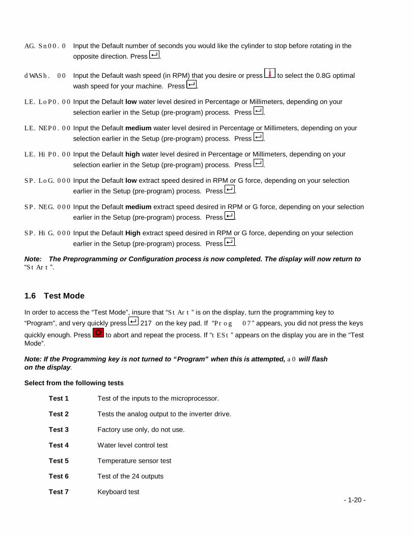
AG.Sn00.0 Input the Default number of seconds you would like the cylinder to stop before rotating in the
opposite direction. Press .
dWASh. 00 Input the Default wash speed (in RPM) that you desire or press to select the 0.8G optimal wash speed for your machine. Press .
LE.LoP0.00 Input the Default low water level desired in Percentage or Millimeters, depending on your
selection earlier in the Setup (pre-program) process. Press . LE.NEP0.00 Input the Default medium water level desired in Percentage or Millimeters, depending on your
selection earlier in the Setup (pre-program) process. Press . LE.HiP0.00 Input the Default high water level desired in Percentage or Millimeters, depending on your
selection earlier in the Setup (pre-program) process. Press . SP.LoG.000 Input the Default low extract speed desired in RPM or G force, depending on your selection
earlier in the Setup (pre-program) process. Press . SP.NEG.000 Input the Default medium extract speed desired in RPM or G force, depending on your selection
earlier in the Setup (pre-program) process. Press . SP.HiG.000 Input the Default High extract speed desired in RPM or G force, depending on your selection
earlier in the Setup (pre-program) process. Press . Note: The Preprogramming or Configuration process is now completed. The display will now return to “StArt”.
1.6 Test Mode In order to access the “Test Mode”, insure that “StArt” is on the display, turn the programming key to
“Program”, and very quickly press 217 on the key pad. If “Prog 07” appears, you did not press the keys
quickly enough. Press to abort and repeat the process. If “tESt” appears on the display you are in the “Test Mode”. Note: If the Programming key is not turned to “Program” when this is attempted, a0 will flash on the display. Select from the following tests Test 1 Test of the inputs to the microprocessor. Test 2 Tests the analog output to the inverter drive. Test 3 Factory use only, do not use. Test 4 Water level control test Test 5 Temperature sensor test Test 6 Test of the 24 outputs Test 7 Keyboard test

- 1-21 -
Once “tESt” appears on the display, select the test that you wish to perform and enter that number. 1.6.1 Test 1: Inputs This test can be used to check all inputs to the PS40. Input 1 = Motor overload protector Input 2 = Programming switch Input 3 = Door lock switch S2 Input 4 = Door lock switch S1 Input 5 = Vibration switch Input 6 = Proximity sensor Input 7 = Inverter balance signal Input 8 = Timer hold The display will indicate whether the input contacts are open or closed using the last character on the right – o for
open, c for closed. Pressing advances you to the next input. Example: “t1.inP.1.o” tells you that Input number 1 is open. “t1.inP.1.c” tells you that Input number 1 is closed. 1.6.2 Test 2: Analog Reference Tests the analog reference output voltage in comparison to the cylinder speed. Note: Because the PS40 does not try to compensate for the speed in this mode running rpm will not necessarily match the commanded rpm – this is normal. After selecting Test 2, the display will show P000u0.00 Press .
The door will now lock. Press . The cylinder will rotate to the left in wash speed and the RPM and analog output will be displayed. l046u0.39 (the numbers on the left indicate running RPM, and the numbers on the right indicate analog voltage) Press . The display will show P000u0.00 Press . The cylinder will rotate to the right in wash speed and the RPM and analog output will be displayed. R046u0.39 Press . The cylinder will rotate in distribution speed and the RPM and analog output will be displayed. d046u0.39 When the drive Smartspin signal turns on, bs will be displayed. Press . The cylinder will rotate low extract speed and the RPM and analog output will be displayed. L335u03.40 Press . The cylinder will rotate to the right in high speed extract and the RPM and analog output will be displayed.
H715u7.20 Press .
The cylinder will return to a stop, and the door will unlock. Press .
- 1-22 -
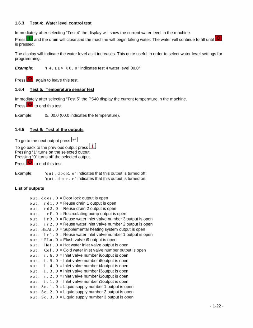
1.6.3 Test 4: Water level control test Immediately after selecting “Test 4” the display will show the current water level in the machine.
Press and the drain will close and the machine will begin taking water. The water will continue to fill until is pressed. The display will indicate the water level as it increases. This quite useful in order to select water level settings for programming. Example: “t4.LEV 00.0” indicates test 4 water level 00.0”
Press again to leave this test. 1.6.4 Test 5: Temperature sensor test Immediately after selecting “Test 5” the PS40 display the current temperature in the machine.
Press to end this test. Example: t5. 00.0 (00.0 indicates the temperature). 1.6.5 Test 6: Test of the outputs To go to the next output press
To go back to the previous output press Pressing “1” turns on the selected output. Pressing “0” turns off the selected output.
Press to end this test. Example: “out.dooR.o” indicates that this output is turned off. “out.door.c” indicates that this output is turned on. List of outputs out.door.0 = Door lock output is open out. rd1.0 = Reuse drain 1 output is open out. rd2.0 = Reuse drain 2 output is open out. rP.0 = Recirculating pump output is open out. ir3.0 = Reuse water inlet valve number 3 output is open out. ir2.0 = Reuse water inlet valve number 2 output is open out.HEAt.0 = Supplemental heating system output is open out. ir1.0 = Reuse water inlet valve number 1 output is open out.iFLu.0 = Flush valve i9 output is open out. Hot.0 = Hot water inlet valve output is open out. Col.0 = Cold water inlet valve number output is open out. i.6.0 = Inlet valve number i6output is open out. i.5.0 = Inlet valve number i5output is open out. i.4.0 = Inlet valve number i4output is open out. i.3.0 = Inlet valve number i3output is open out. i.2.0 = Inlet valve number i2output is open out. i.1.0 = Inlet valve number i1output is open out.So.1.0 = Liquid supply number 1 output is open out.So.2.0 = Liquid supply number 2 output is open out.So.3.0 = Liquid supply number 3 output is open

- 1-23 -
out.So.4.0 = Liquid supply number 4 output is open out.So.5.0 = Liquid supply number 5 output is open out.So.6.0 = Liquid supply number 6 output is open out.So.7.0 = Liquid supply number 7 output is open out.So.8.0 = Liquid supply number 8 output is open out.So.9.0 = Liquid supply number 9 output is open outSo.10.0 = Liquid supply number10 output is open outSo.11.0 = Liquid supply number 11 output is open outSo.12.0 = Liquid supply number 12 output is open outDrA.1.0 = Drain valve number 1 output is open outDrA.2.0 = Drain valve number 2 output is open 1.6.6 Test 7: Keyboard test Immediately after selecting this test “t8. - - “ will appear on the display. The corresponding display for each key pressed on the keypad should be shown on the display.
To end this test press twice. 1.6.7 Ram reset Should it be necessary to erase all of the programming from the PS40s memory, use this procedure. Example: Change of chemical suppliers, where deletion and reprogramming of all programs is required. Corrupted memory. While “Test” is on the display press “0”. “CodE” will now be shown on the display. Very quickly, press “753”. Wait a few seconds for the display to change, then cycle power to the machine. You have now erased everything from memory, and you must setup (pre-program) the machine prior to operation. 1.6.8 PS40 Water level sensor Calibration Procedure 1. Verify that the machine is properly installed. Check water supply and drain connections. 2. Power-up the machine. 3. From the start display, press “ 217” to enter test mode. These buttons must be pressed in rapid
succession. If not entered quickly, the machine will return to the start or prog display and it will be
necessary to press and try again.
4. From the test display, press “4” for water level sensor calibration. 5. Close the door. 6. Press “0” to zero the sensor. Wait for drain to open, the display to zero, and the drain to close. 7. Press to start filling the shell with water.
8. When the water reaches the center of the basket back, press to stop filling. 9. Wait a few minutes for excess water to drain out through the overflow hose and the level to stabilize.

- 1-24 -
10. Press “1” to access the fill measurement. 11. IPH40 – Press “343 “ to enter the correct water level (34.3cm).
IPH60 – Press “394 “ to enter the correct water level (39.4cm). IPH80 – Press “470 ” to enter the correct water level (47.0cm). IPH100 – Press “470 “ to enter the correct water level (47.0cm). IPH140 – Press “546 “ to enter the correct water level (54.6cm).
12. Press to drain the machine.
13. Press to exit test mode. 14. Procedure is complete.
1.7 PS40 Diagnostics
1.7.1 Alarm Codes
Alarm codes are used to alert the operator to problems with the machine’s performance. However, because the alarms do not indicate safety problems they do not interrupt the operation of the machine. When an alarm occurs, the control will flash the code on the program number display to get the operator’s attention. The operator should make note of this code and report it to a technician so the issue can be resolved. Note that all alarm codes are composed of the letter “A” followed by a code reference number.
Code Description A0= The program key was in the wrong position when trying to access the programming mode.
Press to clear. A2 = The program that you have selected, does not exist. Press to clear. A3 = The machine has not been setup (pre-program), or the memory has been lost. Refer to section
6. Press to clear. A4 = The programmed water level was not achieved within 15 minutes. Press to clear. A5= The programmed temperature for supplemental heating was not achieved within 60 minutes.
Press to clear. A6= The temperature in the cylinder is unsafe at the end of a program (Greater than 65C / 150F).
Wait until the load cools to prevent burns. Press to clear. A7= There is water remaining in the machine at the end of the program. Press to clear. A8 = The temperature sensor is not working properly. Press to clear.

- 1-25 -
A9= Rear electrical enclosure too high. Clean the cooling fan filter. Press to clear. Ab = There is already water in the machine when a program was started (check for leaking water
valves). Press to clear. Ac = There was water remaining in the machine after 3 minutes of draining (check for clogged drain).
Press to clear. Ad = The machine is not running at the correct speed, or the speed sensor is damaged. . Press to
clear. AG= The final extract was at a lower than programmed speed (fixed mount machines only). The load
could not be balanced for a fixed speed spin. AH= The final extract was skipped (free standing machines only)
1.7.2 Fault Codes
Fault codes indicate safety issues, which may cause operator injury or property loss. Thus, when an alarm occurs, the control will lock out the machine’s operation until power has been cycled and a technician corrects the problem. Note that all fault codes are composed of the letter “F” followed by a code reference number.
Code Description
F1 = Invalid control configuration or corrupted PS40 firmware. Load a new version or call for service. F5= The door open switch was tripped during the program – the door lock mechanism is
malfunctioning. This problem must be corrected, and the power to the machine cycled in order to clear it.
F6= The door locked switch was tripped during the program – the door lock mechanism is
malfunctioning. The problem must be corrected, and the power to the machine cycled in order to clear it.
FA= The vibration switch is tripped at the beginning of the program. Correct problem and cycle power
to clear.
1.8 Programming Tips • Avoid using spins after the wash program segments. This can cause suspended soil to be redeposited in the
fabric before it can be rinsed out.
• For optimum agitation, program the wash speed at 0.8 G’s (ex. 42 RPM in the IPH60, 38 RPM in the IPH80/100) for the machine you are using. This will give the best drop in the cylinder and the best soil removal.
• Use SmartSpin in programs for processing cotton and other sturdy goods that can take higher extract forces. This will reduce your drying time and energy consumption.
• High spin speeds (> 80Gs) can set wrinkles in goods made of Visa and some other synthetic materials.
• For processing non-porous rubber mats try a long “jolt” drain period instead of a final extract. The jolt routine alternates short spin and tumble segments and will effectively remove water from non-porous goods because they are continuously rearranged, freeing water trapped in pockets.

- 2-26 -
2 PROGRAMMING WORKSHEETS The following sheets are blank programming worksheets. The first sheet is for use in recording your program names (10 blanks are provided, although the PS40 can store 40 programs numbered 0 to 39) and chemical use assignments. This will serve as a convenient reference when you are creating and modifying programs in the future.
Each blank program worksheet is arranged as the information is to be entered in memory. Spaces are provided for each program option – this format makes it possible to layout and program your wash formulas very quickly, and will provide a clear record of what was done for future reference.

- 2-27 -