Embed Size (px)
Citation preview

Study of in house components of the HMT Tractors for Commonization, Process Improvement and Commercialization.
HMt Tractors Limited, pinjore
Birla Institute of Technology and Science, Pilani July, 2015

A REPORT
ON
PROJECT WORK
STUDY OF IN HOUSE COMPONENTS OF THE HMT TRACTORS FOR COMMONIZATION, PROCESS IMPROVEMENT AND COMMERCIALIZATION.
BY
AKSHIT ANAND 2013B3A8536G
ANKUR MITTAL 2013B5A4622P
SWARN SINGH BHAL 2013B1AB374P
ADITYA TAANK 2013A4PS335H
KSHITIJ KUMAR 2013B4A4513G
PARTH GUPTA 2013A4PS369H
AT
HMT TRACTORS LIMITED, PINJORE
A Practice School-I station of
BIRLA INSTITTUE OF TECHNOLOGY & SCIENCE, PILANI
(July, 2015)
Birla Institute of Technology and Science, Pilani July, 2015

Project Report 1Research & Development Department
Acknowledgement
We would like to thank all the officials of HMT Tractors, Pinjore for their guidance and constant supervision. Their experience and advice builds a platform for efficient learning in a short span of time. We are extremely grateful to Mr Sunil Kathuria and Mr. Srinivas Sharma for taking time out of their busy schedule to explain us all the designs of the in-house components and guiding us throughout the commonization part of the project. We would also like to thank Mr. Ved Prakash and Mr. N. D. Sharma for helping us understand the processes involved in the manufacturing of the connecting rod.
Last but not the least, we would also like to express our deep gratitude to our PS Instructor, Dr. Paul Atish Tulshiram, and the Co-instructor, Ms. Sonia Antil for their patient guidance and enthusiastic encouragement which made this learning process even more interesting.
We also wish to acknowledge everyone who played a role in guiding me through this project.
Birla Institute of Technology and Science, Pilani July, 2015

BIRLA INSTITUTE OF TECHNOLOGY AND SCIENCE
PILANI (RAJASTHAN)
Practice School Division
Station: Pinjore Centre: HMT Tractors Limited
Duration: From: 22nd May, 2015 To: 16th July, 2015
Date of Submission: 10th July, 2015
Title of the Project: To study the in house components of the HMT Tractors for Commonization, Process Improvement and Commercialization.
ID No: 2013B3A8536G Name of Student: Akshit Anand Discipline: B.E. EnI / Economics
2013B5A4622P Ankur Mittal B.E. Mechanical / Physics
2013B1AB374P Swarn Singh Bhal B.E. Manufac. / Biology
2013A4PS335H Aditya Taank B.E. Mechanical
2013B4A4513G Kshitij Kumar B.E. Mechanical / Maths
2013A4PS369H Parth Gupta B.E. Mechanical
Name(s) of expert: Mr. K.S.Nagi Designation: Joint General Manager
Name of PS Faculty: Dr. Paul Atish Tulshiram
Key Words: Bearing, Connecting Rod, Commonization, Process Improvement and Commercialization
Project Area(s): Research & Development, Manufacturing.
Abstract: This report is based on the study of various in-house components manufactured in HMT Tractors, Pinjore. Initially it discusses important systems viz. Engine, transmission and electronic controls involved in tractor machinery. It includes our analysis and proposal regarding the commonization of bearings present in the main shaft of tractors 6522 and 4922. It also covers the processes involved in the production of connecting rod and our suggestions to improve the efficiency of the process in terms of time and cost.
Signature of student Signature of PS Faculty
Date: 10th July, 2015 Date
Birla Institute of Technology and Science, Pilani July, 2015

Project Report 1Research & Development Department
Table of Contents
Introduction …………………………………………………………………........ 1
1 Engine1.1 Important Engine Parts …………………………………………... 2-61.2 Suggestion ………………………………………………………... 7
2 Electrical components of a tractor ……………………………………………….. 83 Transmission ……………………………………………………………………... 94 Commonization
4.1 Aim ………………………………………………………………. 114.2 Objective …………………………………………………………. 114.3 Procedure ……………………………………………………….... 114.4 Theory ……………………………………………………………. 114.5 Calculations ………………………………………………………. 154.6 Proposal ………………………………………………………...… 204.7 Practical Representation ………………………………………….. 23
5 Process Improvement5.1 Aim ……………………………………………………………….. 265.2 Objective ………………………………………………………….. 265.3 Theory …………………………………………………………….. 265.4 Current Procedure ………………………………………………… 265.5 Proposed Procedure ……………………………………………….. 275.6 Calculations ……………………………………………………….. 285.7 Practical Representation ………………………………………...… 30
6 Commercialization6.1 Bearing Commercialization ……………………………………….. 336.2 Commercialization for Connecting Rod ………………………....... 35
7 Conclusion …………………………………………………………………...……. 368 References …………………………………………………………………...…….. 379 Glossary …………………………………………………………………...………. 38
Birla Institute of Technology and Science, Pilani July, 2015

Project Report 1Research & Development Department
Introduction
HMT Tractors is renowned for its technical expertise and early adaptation of modern technologies. This has been possible due to its robust Research and Development Department which has successfully adapted the foreign technologies keeping in mind the conditions which prevail in the Indian Subcontinent. The primary role of R&D is to design, test and analyze the new components and techniques which can be used in the production of tractors and its implements. An added challenge in recent times has been to adapt the current designs in accordance to ever changing consumer requirements and regulatory norms.
This project report deals with the study of in-house components. Components which require certain technical skills are manufactured in the facility itself. Whereas, those components which require labor intensive approach are outsourced. Examples of in-house components produced at HMT includes Gears (both timing and transmission), Connecting Rod, Crank shaft, Crank case, Cylinder head, Gear axle housing, Direct axle housing and MT housing
Birla Institute of Technology and Science, Pilani July, 2015

Project Report 1Research & Development Department
ENGINE
Engine is crucial part of tractor. It is the powerhouse which generates power. The important parts of the engine are discussed below.
1.1 IMPORTANT ENGINE PARTS:
a. Flywheel:
A flywheel is a rotating mechanical device that is used to store rotational energy. Flywheels have a significant moment of inertia and thus resist changes in rotational speed. The amount of energy stored in a flywheel is proportional to the square of its rotational speed. Energy is transferred to a flywheel by applying torque to it, thereby increasing its rotational speed, and hence its stored energy. Conversely, a flywheel releases stored energy by applying torque to a mechanical load, thereby decreasing the flywheel's rotational speed.
Common uses of a flywheel include:
Providing continuous energy when the energy source is discontinuous. For example, flywheels are used in reciprocating engines because the energy source, torque from the engine, is intermittent.
Delivering energy at rates beyond the ability of a continuous energy source. This is achieved by collecting energy in the flywheel over time and then releasing the energy quickly, at rates that exceed the abilities of the energy source.
Controlling the orientation of a mechanical system. In such applications, the angular momentum of a flywheel is purposely transferred to a load when energy is transferred to or from the flywheel.
Birla Institute of Technology and Science, Pilani July, 2015
Project Report 2Research & Development Department
b. Timing Gears:
The timing gear is connected by chain, gears, or a belt to the crankshaft at one end and the camshaft on the other. It is marked with tiny increments all around its perimeter, which correspond to degrees of timing from the straight-up timing position of the camshaft and crankshaft. These marks assist the individual who is tuning up the engine to set the timing to the determined optimal timing degrees of the camshaft and engine designers.
c. Lubrication system:
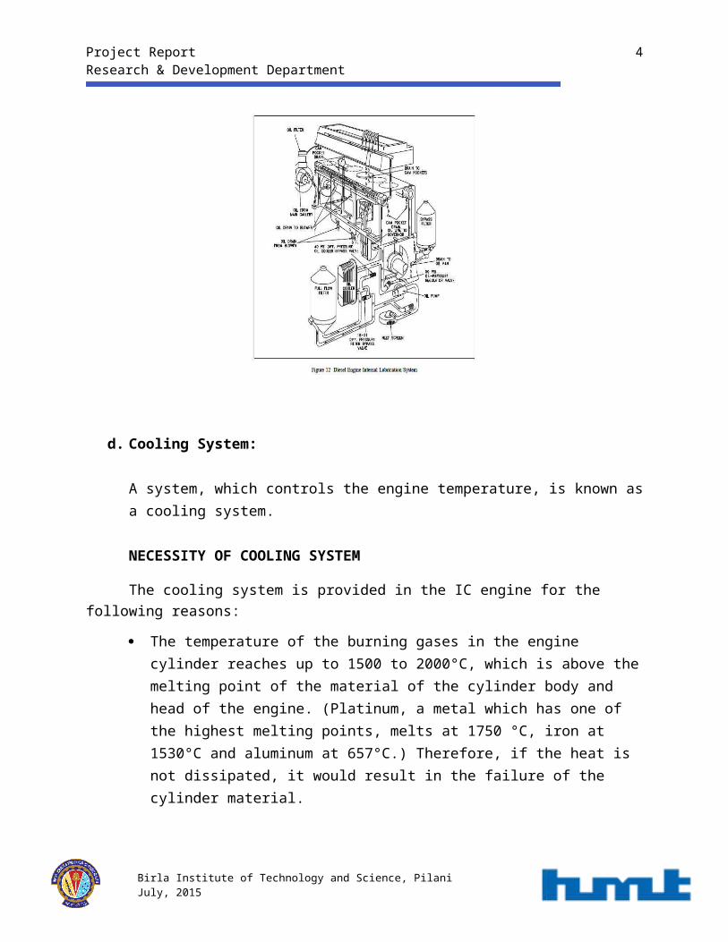
An internal combustion engine would not run for even a few minutes if the moving parts were allowed to make metal-to-metal contact. The heat generated due to the tremendous amounts of friction would melt the metals, leading to the destruction of the engine. To prevent this, all moving parts ride on a thin film of oil that is pumped between all the moving parts of the engine.Oil is accumulated and stored in the engine's oil pan where one or more oil pumps take suction and pump the oil through one or more oil filters as shown in Figure 12. The filters clean the oil and remove any metal that the oil has picked up due to wear. The cleaned oil then flows up into the engine's oil galleries. A pressure relief valve(s) maintains oil pressure in the galleries and returns oil to the oil pan upon high pressure. The oil galleries distribute the oil to all the bearing surfaces in the engine.Once the oil has cooled and lubricated the bearing surfaces, it flows out of the bearing and gravity-flows back into the oil pan. In medium to large diesel engines, the oil is also cooled before being distributed into the block. This is accomplished by either an internal or external oil cooler. The lubrication system also supplies oil to the engine's governor.
HMT system has an oil-pump of capacity 7-8 kg/cm.cm.
Birla Institute of Technology and Science, Pilani July, 2015
Project Report 3Research & Development Department
d. Cooling System:
A system, which controls the engine temperature, is known as a cooling system.
NECESSITY OF COOLING SYSTEM
The cooling system is provided in the IC engine for the following reasons:
The temperature of the burning gases in the engine cylinder reaches up to 1500 to 2000°C, which is above the melting point of the material of the cylinder body and head of the engine. (Platinum, a metal which has one of the highest melting points, melts at 1750 °C, iron at 1530°C and aluminum at 657°C.) Therefore, if the heat is not dissipated, it would result in the failure of the cylinder material.
Due to very high temperatures, the film of the lubricating oil will get oxidized, thus producing carbon deposits on the surface. This will result in piston seizure.
Due to overheating, large temperature differences may lead to a distortion of the engine components due to the thermal stresses set up. This makes it necessary for, the temperature variation to be kept to a minimum.
Birla Institute of Technology and Science, Pilani July, 2015

Project Report 4Research & Development Department
Higher temperatures also lower the volumetric efficiency of the engine.
REQUIREMENTS OF EFFICIENT COOLING SYSTEM
The two main requirements of an efficient cooling system are:
It must be capable of removing only about 30% of the heat generated in the combustion chamber. Too much removal of heat lowers the thermal efficiency of the engine.
It should remove heat at a fast rate when the engine is hot. During the starting of the engine, the cooling should be very slow so that the different working parts reach their operating temperatures in a short time.
TYPES OF COOLING SYSTEM
There are two types of cooling systems:’
i. Air cooling system andii. Water-cooling system.
Birla Institute of Technology and Science, Pilani July, 2015

Project Report 5Research & Development Department
AIR COOLING SYSTEM:
In this type of cooling system, the heat, which is conducted to the outer parts of the engine, is radiated and conducted away by the stream of air, which is obtained from the atmosphere. In order to have efficient cooling by means of air, providing fins around the cylinder and cylinder head increases the contact area.
LIQUID (WATER) COOLING SYSTEM:
HMT uses liquid cooling system in its tractors. Generally liquid used for cooling in tractors is water.
It serves two purposes in the working of an engine:
i. It takes away the excessive heat generated in the engine and saves it from overheating.
ii. It keeps the engine at working temperature for efficient and economical working.
This cooling system has four types of systems:
i. Direct or non-return systemii. Thermo-Syphon system
iii. Hopper systemiv. Pump/forced circulation system
e. Idler gear/Idler Wheel drive:
An idler-wheel drive is a system used to transmit the rotation of the main shaft of a motor to another rotating device.
An idler gear is a gear wheel that is inserted between two or more other gear wheels. The purpose of an idler gear can be two-fold. Firstly, the idler gear will change the direction of rotation of the output shaft. Secondly, an idler gear can assist to reduce the size of the input/output gears whilst maintaining the spacing of the shafts.
Birla Institute of Technology and Science, Pilani July, 2015
Project Report 6Research & Development Department
1.2 Suggestion
COMMON RAILS SYSTEM:
By contrasts with other systems which build up pressure for each new injection cycle, common rail system uncouples injection from generation of pressure.
A fuel rail serves as a high pressure accumulator. Fuel pressure matched to operating state of the engine is permanently available in this rail.
How does it work ?
The uncoupling of pressure generation and engine speed provides engine designers with new possibilities for the application of the injection sequence, fuel metering and atomization of fuel. With the common rail system, high injection pressures and thus a more complete combustion of the fuel are possible even at low engine speeds. This reduces, in particular, formation of black smoke. At the same time, engine torque can be increased in the lower engine speed range.
Application to HMT engines:
Common rail system can easily be adapted to existing HMT diesel engines with direct injection. It consists of the high pressure pump, the fuel injector lines, high pressure accumulator (common rail), the injectors, the electronic control unit as well as sensors and actuators. Conventional injection equipment can be replaced by the common rail systems with very few alterations to the diesel engine being required. A high pressure pump is installed in place of the previously use injection pump. The injectors can be fitted in the cylinder head like nozzle holder assembly.
Alloys used for manufacturing:
i. Push Rod : seamless CEW steelii. Oil pan : 4 cylinder- cast iron, 3 cylinder- sheet metal
iii. Camshaft : SG iron
Birla Institute of Technology and Science, Pilani July, 2015

Project Report 7Research & Development Department
2. ELECTRICAL COMPONENTS OF A TRACTOR
Electrical components are an important part of the tractor. Some ofthe important components of the tractor are:
i. Alternatorii. Starter Motor
iii. Control Switchesiv. Batteryv. Wiring
vi. Lights and light signals
Battery is the power source of the tractor. It powers all the electrical components in the tractor.The battery used is a 12V DC battery. All the current in the tractor flowing is the DC current. The capacity of the battery is 88 Ah. Another component which is crutial to battery is the Alternator. The alternator is rotated by the engine and its main work is to charge the battery while engine is running. The control switch is placed at the center of the dashboard, its main purpose is to control main switches of all the wirings done in the tractor. The starter motor helps to start the engine.
Apart from the above components, there are devices used for various measurements:
i. Fuel gaugeii. Oil pressure gauge
iii. Water temperature gaugeiv. Speedometer
Fuel gauge measures the level of fuel in the fuel tank. The principle on which it works is variable resistance. Oil pressure gauge measures the pressure of engine oil whereas the water temperature gauge measures the temperature in the engine. The speedometer measures the rpm of the tractor from which speed can be calculated further.There is also a hazard warning switch on the dashboard which causes all the light to flash simultaneously. The fleshes are at the rate of 90+30 flashes per minute. It basically warns other vehicles for some danger. All the lights are manufactured and used according to the CMVR act.
Birla Institute of Technology and Science, Pilani July, 2015

Project Report 8Research & Development Department
3. TRANSMISSION
Transmission is the mechanism by which power is transmitted from the engine to the axle of the automobile. Gears and transmission section is the functional support of the tractor. It is one of the most sophisticated part of the tractor, therefore the performance of the tractor depends highly on this section. All the gears are mounted on the bearings. The ratio of gears in the gearbox is directly related to the performance.
One of the most important issues in the transmission is tolerance. If the tolerance is not proper the gears will start making noise. Precision is must here. The structure of the engine components is:
Another important thing in the gear box is the Inertia of breaking. Its main role is to slow down the motion of the gears in the gearbox when the gears are changed or the breaks are applied. A synchronous gear box tries to do the same by bringing the relative angular motion to zero
Birla Institute of Technology and Science, Pilani July, 2015
Engine Clutch Transmission
Differential Final Drive

Project Report 9Research & Development Department
Birla Institute of Technology and Science, Pilani July, 2015
4. Commonization

Project Report 10Research & Development Department
4.1 Aim: To study the in house components of HMT tractors, replace and commonize them.
4.2 Objective:
i. To use uniform bearings with best output (Maximum life).ii. To reduce the number of parts.
iii. To reduce the cost.
4.3 Procedure:
Commonization deals with studying of the engine parts, doing the calculations and then replacing the used components with the (which have to be more than two) theoretical one.
Our area of focus was the main shaft used in the gearbox for torque transmission. The project deals with the two models of tractor, the 6522 model and the 4922 model. In 6522 model there are 2 bearings each at the opposite ends of the gears (1,2,3,4,5,R) whereas in case of 4922 model, the main shaft contains 3 bearings at the opposite ends of the gears (1,2,3,4,R) one on the left and the other two at right. The left bearing used was needle bearing and the one used at the right was radial deep groove bearing.
Why was the main shaft chosen, in spite there being two more shaft – lay and PTO shaft. The main shaft (as the name suggests) is the controller which maintains the link to the other shafts when the gears are engaged. Therefore we will be conducting our analysis on the main shaft of both the tractors. The theory and calculations are as follows:
4.4 Theory:
a. Dynamic Capacity: Dynamic Capacity of a bearing is the constant radial load it can support during 1,000,000 revolutions before the first signs of fatigue appear on a bearing or rolling element.
b. Nominal life: Nominal life of a radial or thrust bearing is the total number of revolutions it made during its lifetime.
L10=( CP )
p
Birla Institute of Technology and Science, Pilani July, 2015
Project Report 11Research & Development Department
L10 = Basic Rating Life (10^6 Revolutions)
C: Basic Dynamic Load Rating (N)
P: Equivalent Dynamic Load
P: Constant which is 10/3 for needle or roller bearing and 3 for ball bearing.
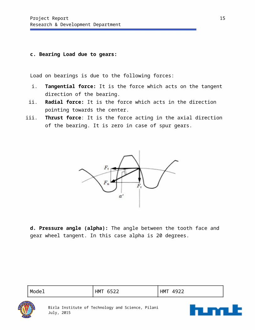
c. Bearing Load due to gears:
Load on bearings is due to the following forces:
i. Tangential force: It is the force which acts on the tangent direction of the bearing.ii. Radial force: It is the force which acts in the direction pointing towards the center.
iii. Thrust force: It is the force acting in the axial direction of the bearing. It is zero in case of spur gears.
d. Pressure angle (alpha): The angle between the tooth face and gear wheel tangent. In this case alpha is 20 degrees.
Birla Institute of Technology and Science, Pilani July, 2015

Project Report 12Research & Development Department
Model HMT 6522 HMT 4922
Bearings Needle cage Rad. Bearing Needle bearing
Rad. bearing
Bearing Designation/Number 9923 5114 6311 9923 5328 6011
Dynamic Capacity (KN) 29 56.2 44.24 21.756
Pressure angle 20 20
Dimensions 25/33x20 55x120/29 21/4x21.8 55x90/18
e. Types of force acting on gear:
Tangential force:
F t=2000 Td
Radial force:
F r=F t tanα
Birla Institute of Technology and Science, Pilani July, 2015

Project Report 13Research & Development Department
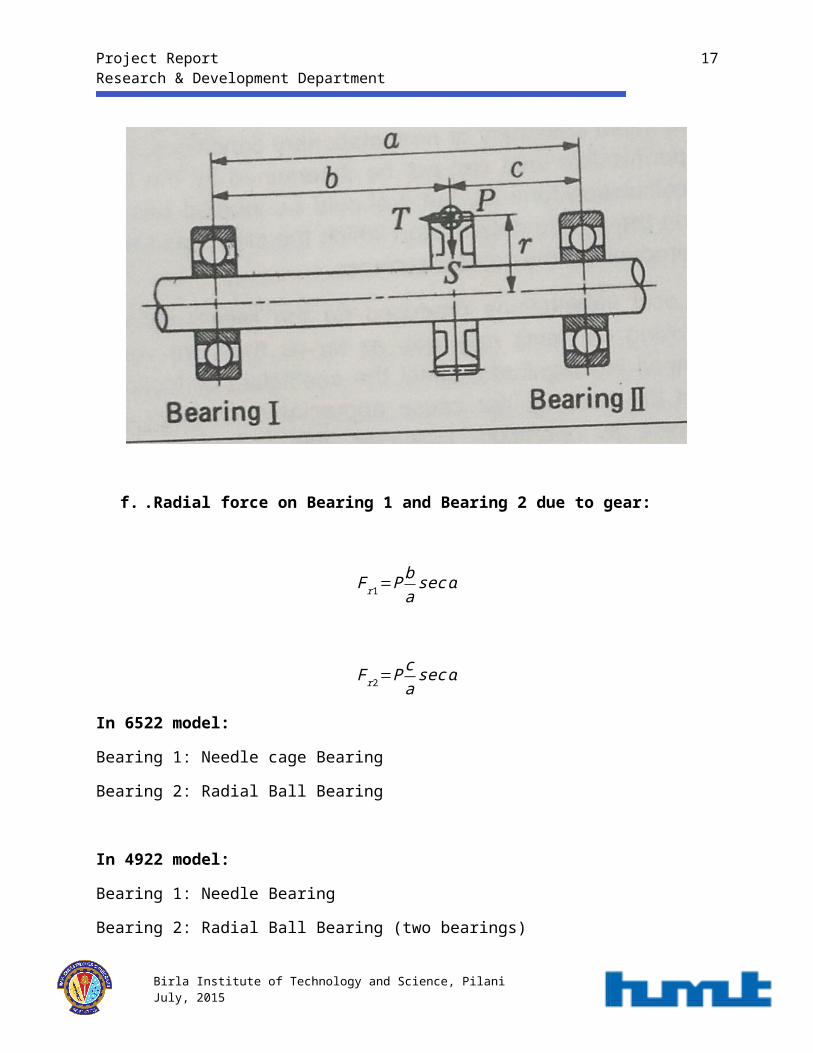
f. .Radial force on Bearing 1 and Bearing 2 due to gear:
F r1=P ba
secα
F r2=P ca
sec α
In 6522 model:
Bearing 1: Needle cage Bearing
Bearing 2: Radial Ball Bearing
In 4922 model:
Bearing 1: Needle Bearing
Bearing 2: Radial Ball Bearing (two bearings)
Birla Institute of Technology and Science, Pilani July, 2015

Project Report 14Research & Development Department
4.5 Calculations:
Calculation for 6522:
Let us suppose for gear 2:
a = 308.75 mm
b = 182 mm
c = 126.75 mm
z =35.88 KN-m (provided by HMT)
P=20 zd
P=20 50.51108 ×10⁻³
P=9.353KN
Therefore,
F r1=P ca
secα=4.0865 KN
F r2=P ba
sec α=5.867 KN
Similarly, the results for the calculations for other gears are:
Parameters Gear 1 Gear 3 Gear 4 Gear Reverseb (m) 210.5 111 85.25 258.25c (m) 98.25 197.25 223.0 50.5z (KNm) 38.5 35.8 28.77 42.1P (N) 5833.33 8154.54 7571.05 6368.11d (mm) 132 88 76 132Fr1 (KN) 1.975 5.558 5.819 1.108Fr2 (KN) 4.232 3.119 2.237 5.668
Birla Institute of Technology and Science, Pilani July, 2015

Project Report 15Research & Development Department
Nominal Life:
L10=105
6 nm×( C
P )p
Where,
L10 : Basic Rating Life (hours)
C : Basic Dynamic Load Rating (N)
P : Equivalent Dynamic Load (N)
p : A constant whose value is 10/3 for needle bearing and 3 for ball bearing
Equivalent Load:
Peq=p√ ( F1)3n1 t1+( F2 )3 n2+…uptono . of gearsn1 t1+n2t 2+…upto no . of gears
Equivalent RPM:
nm=n1 t 1+n2t 2+… uptono .of gears
t 1+ t2+…upto no . of gears
Where,
Fn: Radial force on nth gear
nn : RPM on nth gear
tn :Time for which nth gear was engaged
Birla Institute of Technology and Science, Pilani July, 2015

Project Report 16Research & Development Department
Usage ratios:
n1= 506; t1 = 19%
n2= 750; t2= 19%
n3= 1056; t3= 19%
n4= 1317; t4= 19%
nr = 887; tr= 5%
Note: Contribution of 4th gear is insignificant as it is engaged on different shaft.
N=∑ ni ti=733.86 RPM
Peq (for Radial Ball Bearing) = 4.15 KN
Peq (Needle cage Bearing) = 5.08 KN
Life (Radial) = 53000 hours
Life (Needle cage) = 7506 hours
Calculation for 4922:
Note:In case of 4922 model there are two bearings at the right end of the main shaft.
Let us suppose for gear 2:
A = 246.5 mm
b= 143 mm
c= 103.5 mm
z=42.5 KN-m (provided by HMT)
Birla Institute of Technology and Science, Pilani July, 2015
Project Report 17Research & Development Department
Therefore,
Force on Bearing 1 and Bearing 2 (and Bearing 3 on right end) due to gear 2:
P=20 zd
P=20 42.596 ×10⁻³
P=8.812KN
F r 1=P ca
secα=3.9570 KN
F r 2=P ba
sec α=5.4673 KN
Similarly, the results for the calculations for other gears are:
Parameters Gear 1 Gear 2 Gear 3 Gear Reverseb (mm) 167 143 59 215.75c (mm) 79.5 103.5 187.5 30.75z (KNm) 25.02 42.5 25.02 39.76P (N) 9610 8856 7942 7362.9d (mm) 108 96 63 108Fr1 (KN) 1.6004 3.9570 6.4287 9.7870Fr2 (KN) 3.362 5.4673 2.0230 6.8674
Nominal Life
L10=105
6 nm×( C
P )p
Where,
Birla Institute of Technology and Science, Pilani July, 2015

Project Report 18Research & Development Department
L10 : Basic Rating Life (hours)
C : Basic Dynamic Load Rating (N)
P : Equivalent Dynamic Load (N)
p :A constant whose value is 10/3 for needle bearing and 3 for ball bearing
Equivalent Load:
Peq=p√ ( F1)3n1 t1+( F2 )3 n2+…uptono . of gearsn1 t1+n2t 2+…upto no . of gears
Equivalent RPM:
nm=n1 t 1+n2t 2+… uptono .of gears
t 1+ t2+…upto no . of gears
Where,
Fn: Radial force on nth gear
nn : RPM on nth gear
tn :Time for which nth gear was engaged
Usage ratios:
n1= 562.2; t1 = 16%
n2= 840; t2= 20%
n3= 1414; t3= 24%
Birla Institute of Technology and Science, Pilani July, 2015
Project Report 19Research & Development Department
nr= 1026.2; tr= 16%
Note:Contribution of 4th gear is insignificant as it is engaged on different shaft.
N=∑ ni ti=761.584 RPM
Peq on one of the radial bearings on the right end = 2.407 KN
Peq (Needle bearing) = 5.16 KN
Life of one the radial bearing on right end = 16231.2 hours
Life (Needle bearing) = 28047.2 hours
4.6 Proposal:
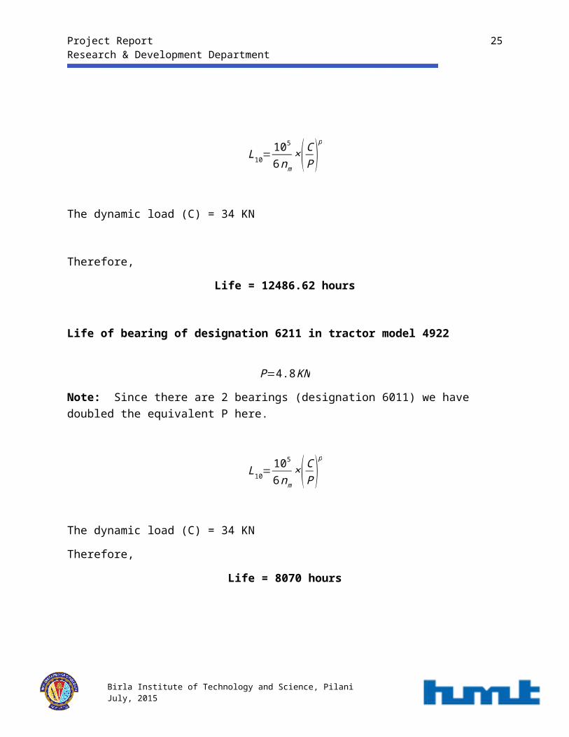
Based on above calculations we propose that the radial ball bearing used in tractor model 6522 (designation 6311) and the radial ball bearing used in the tractor model 4922 (designation 6011) can be replaced by another radial ball bearing of designation 6211.
Life of bearing of designation 6211 in tractor model 6522
P=4.15 KN
L10=105
6 nm×( C
P )p
The dynamic load (C) = 34 KN
Therefore,
Birla Institute of Technology and Science, Pilani July, 2015

Project Report 20Research & Development Department
Life = 12486.62 hours
Life of bearing of designation 6211 in tractor model 4922
P=4.8 KN
Note: Since there are 2 bearings (designation 6011) we have doubled the equivalent P here.
L10=105
6 nm×( C
P )p
The dynamic load (C) = 34 KN
Therefore,
Life = 8070 hours
Birla Institute of Technology and Science, Pilani July, 2015

Project Report 21Research & Development Department
A graph depicting the torque on each gear
Birla Institute of Technology and Science, Pilani July, 2015

Project Report 22Research & Development Department
4.7 Practical Representation
The transmission system in the 4922 tractor model
The bearings on the left hand side is the radial ball bearings (two bearings) and the on the right and side is the needle bearing. In our proposition the radial ball bearing is being replaced by a suitable one.
Birla Institute of Technology and Science, Pilani July, 2015

Project Report 23Research & Development Department
Gear box model
Radial Ball Bearing
Birla Institute of Technology and Science, Pilani July, 2015

Project Report 24Research & Development Department
Birla Institute of Technology and Science, Pilani July, 2015
5. Process Improvement

Project Report 25Research & Development Department
5.1 Aim: To study the process of manufacturing of connecting rod and suggest improvements.
5.2 Objectives:
To prevent wastage of material To reduce cost of production To make the process more time-efficient
5.3 Theory:
In a reciprocating piston engine, the connecting rod connects the piston to the crank or crankshaft. Together with the crank, they form a simple mechanism that converts reciprocating motion into rotating motion.
Connecting rods may also convert rotating motion into reciprocating motion. Historically, before the development of engines, they were first used in this way.
As a connecting rod is rigid, it may transmit either a push or a pull and so the rod may rotate the crank through both halves of a revolution, i.e. piston pushing and piston pulling.
5.4 Current Procedure:
Following are the processes undergone in the manufacturing of connecting rod:
Birla Institute of Technology and Science, Pilani July, 2015

Project Report 26Research & Development Department
Process Time Required (min) Description1. Surface Grinding 10-14 Both faces to
dimension 42.62. Drilling - Small end dia ϕ38 X
42.63. Boring 3 Φ39.5, ϕ604. Straddle-milling 2 -5. Broaching 3 -6. Number Punching 1-2 sec -7. Slitting 2-2.5 Slit at dim. 220.58. Top Grinding 2 Grind face 94 (4mm
reduced)9. Multi-spindle Drilling 4 -10. Bolt-fastening 4 -11. Grinding 10 -12. Boring 3.5 ϕ 63.313. Lock-making 1 -14. Fine-boring 3 Φ40, ϕ6415. Bush-fastening 0.5 Φ3416. Drilling 1 6mm (Passage for Lub.
Oil)17. Spot-facing 1.5 -18. Bush-boring 1.5 Φ3519. Notching 1 -20. Fresh bolts are fastened - -21. Inspection 2-5 Twisting for
straightening
5.5 Proposed procedure:
1. Currently, the final inspection and correction (21) is done on a manual press which might result in inaccuracies and is time-consuming. Alternatively, an automatic hydraulic press will take just around 0.5 min. and will reduce human error.
Birla Institute of Technology and Science, Pilani July, 2015
Project Report 27Research & Development Department
2. Proposed alternative to slitting (7):
Presently the connecting rod is being slit by a horizontal disc milling cutter which cuts out 8mm of material and takes 2-2.5 min. This result in high material wastage, thereby increasing the cost of machining as well as that of the forging procured.
Another cutting machine available at HMT is the BAND SAW.It is a power tool which uses a blade consisting of a continuous band of metal with teeth along one edge to cut various work pieces. The band rides on two wheels rotating in the same plane. Band sawing produces uniform cutting action as a result of an evenly distributed tooth load.It is particularly useful for cutting irregular or curved shapes, but can make straight cuts and is quite reliable. The minimum radius of a curve that can be cut on a particular saw is determined by the width of the band and its kerf.
Advantages:
Metal section reduction = 6.5mm Time saved = 1.5 min./work piece
5.6 Calculations:
Area of cross section = 4.48 cm2
Density of material = 7.85 gm/cm3
Volume of material saved = 2 × 3.14 cm3
= 6.28 cm3
Birla Institute of Technology and Science, Pilani July, 2015

Project Report 28Research & Development Department
Cross sectional view of connecting rod
Net material saved = Gross material saved + Forging and shrinkage allowance = (6.28 + 20% of 6.28)
= 7.536 cm3
Therefore, mass of material saved = 7.536 × 7.85
= 59.157 gm
Birla Institute of Technology and Science, Pilani July, 2015

Project Report 29Research & Development Department
5.7 Practical Representation
Currently used machine for slitting
Currently the slit in the connecting rod is made by a machine named slitter which makes an 8mm slit and wastes a lot of material. The purpose can be solved by a similar process which uses a machine named BAND SAW and makes only a 1.5 mm slit. This is depicted in the following pictures.
Birla Institute of Technology and Science, Pilani July, 2015

Project Report 30Research & Development Department
The BAND SAW machine
Birla Institute of Technology and Science, Pilani July, 2015

Project Report 31Research & Development Department
Connecting rod forging after the slit
Birla Institute of Technology and Science, Pilani July, 2015
6. Commercialization

Project Report 32Research & Development Department
Commercialization
Commercialization or commercialisation is the process of introducing a new product or production method into commerce—making it available on the market. Following are the things which the calculations in the earlier parts of the project led us to:
6.1 Bearing commercialization:
Following are the bearings being used and proposed first part of the project:
Bearing Designation Cost ( )₹
6011 115
6211 160
6311 320
Birla Institute of Technology and Science, Pilani July, 2015

Project Report 33Research & Development Department
Following are the taxes applicable on the ordering of the materials:
Taxes applicable Percentage
Excise duty 12.5%
Central Sales Tax (CST) 2%
Local Area Development Tax (LADT) 0.6%
Therefore, the final cost with the taxes are:
Bearing Designation Cost with taxes( )₹
6011 132.365
6211 184.16
6311 368.32
Following are the calculations which leads to the cost reductions and profits:
Cost reduction in 4922 model:
As proposed earlier, instead of two Radial Ball Bearings of designation 6011, one Radial ball Bearing of designation 6211 can be used.
Therefore cost reduced =2*(132.365) – 184.16
= ₹ 80.57
Cost reduction in 6522 model:
Birla Institute of Technology and Science, Pilani July, 2015

Project Report 34Research & Development Department
As proposed earlier, instead of Radial Ball Bearing of designation 6311, Radial ball Bearing of designation 6211 can be used.
Therefore cost reduced = 368.32 – 184.16
= ₹ 184.16
6.2 Commercialization for connecting rod:
As we have used BAND SAW in the proposed procedure, it reduces the size of the slit and therefore reduces the material and cost of the forging being ordered currently.
Cost of material per gram of forging = 0.129 /gram₹
Mass of material saved = 59.157 grams
Cost of material saved = 59.157*(0.129)
= ₹ 8.77
Birla Institute of Technology and Science, Pilani July, 2015

Project Report 35Research & Development Department
6. Conclusion
Based on our experience on this project it is evident that although the current procedures used in the planning and manufacturing of tractor as well as machine tools parts in the organization are efficient but there is still scope for improvement.
After studying the transmission drawings for 6522 and 4922 model we found that bearings were one part where commonization can play crucial role.
Guidance from Mr. Ved Prakash and Mr. N.D. Sharma helped us to identify the inefficiency in the process of machining of connecting rod.
Further the data from the Department of Purchase and Contracts helped us to perform commercialization on the calculations obtained.
Still we found that there is a lot more scope for improvement in future. For example, commonization of bearings in the lay shaft and process improvement in the manufacturing of crank case. Moreover we can also implement CNC machines in the manufacturing of connecting rods.
Birla Institute of Technology and Science, Pilani July, 2015

Project Report 36Research & Development Department
7. References
Organization officials:
Mr. Sunil Kathuria – Deputy Chief Engineer
Mr. K.S.Nagi – Joint General Manager
Mr. Srinivas Sharma – Deputy Chief Engineer DesignMr. Ved Prakash – Manager Planning
Mr. Narendra Singh – Manager Planning
Mr. Kulwant Singh – Manager Design
Mr. N.D Sharma – Planning
Mr. Manish Varshney – Information regarding purchase
Web links:
http://webtools3.skf.com/BearingCalc
Birla Institute of Technology and Science, Pilani July, 2015

Project Report 37Research & Development Department
http://www.hmtbearings.co.in/
Text Material:
HMT bearing catalogues
HMT tractor model catalogues
Model Blueprints
8. Glossary
Band Saw - power tool which uses a blade consisting of a continuous band of metal with teeth along one edge to cut various work pieces.
Central Sales Tax - a form of indirect tax imposed only on goods sold from one state to another state, which particularly takes into account that the buyer and the seller needs to be in two different states.
Clearance - clearance, is the internal radial looseness in a bearing and is the measured value of the total radial movement of the outer ring with respect to the inner ring in a plane perpendicular to the bearing axis.
Birla Institute of Technology and Science, Pilani July, 2015

Project Report 38Research & Development Department
Commercialization - process of introducing a new product or production method into commerce—making it available on the market.
Common Rail System - Common rail direct fuel injection is a direct fuel injection system for petrol and diesel engines which features a high-pressure (over 1,000 bar or 100 MPa or 15,000 psi) fuel rail feeding individual solenoid valves, as opposed to a low-pressure fuel pump feeding unit injectors (or pump nozzles).
Differential – a mechanism designed to drive a pair of wheels while allowing them to rotate at different speeds.
Dynamic Load Rating (C) - load, constant in magnitude and direction, under which a given basic rating life (corresponding to a given total distance travelled) can be achieved under constant rotation or oscillating movement at a defined sliding velocity at room temperature.
Equivalent Load (P) – a hypothetical load (radial for a radial bearing and axial for a thrust bearing) which, when applied, would cause the same maximum rolling element load in the bearing as the actual loads to which the bearing is subjected.
Excise Tax - an inland tax on the sale, or production for sale, of specific goods or a tax on a good produced for sale, or sold, within a country or licenses for specific activities.
Birla Institute of Technology and Science, Pilani July, 2015

Project Report 39Research & Development Department
Forging - manufacturing process involving the shaping of metal using localized compressive forces.
Idler Wheel - system used to transmit the rotation of the main shaft of a motor to another rotating device.
Tolerance - machine's potential to cope with changes in the following elements of its surroundings and remain functioning.
Transmission - mechanism by which power is transmitted from the engine to the axle of the automobile.
Birla Institute of Technology and Science, Pilani July, 2015