Embed Size (px)
Citation preview

US Praxis, Inc. – Copyright 2009 © All rights reserved 1
PRX90 & PRX130 OPERATIONS & OWNERS MANUAL
US Praxis, Inc. 955 W. Prairie Drive Sycamore, IL 60178
Toll Free: (888) 3168200 Ph: (815) 8999700 Fax: (815)8999709
Web: www.uspraxis.com

US Praxis, Inc. – Copyright 2009 © All rights reserved 2
TABLE OF CONTENTS
Praxis Stump Machines PRX90 & PRX130
Introduction………………………………3 Use & Service………..………………….3
Safety Instructions……………………….4 General Use………………...……………4
Preparing to Use………..….…………….6
Protective Equipment…..….………..…...8
Operating……..………..….……………..9
Movement/Transport.…..….………...…10 Storage…..…………….….……………10 Fuel System………..…………………...11 Maintenance………...……………..…...12
Controls………………………………….13 Engine…………………….……………13 Throttle…..……… ……………………13 Starter……….……........………………13 Starter Handle…….……………………14 Fuel Valve.….…….……………………14 Choke Control…….……………………14 Air Filter….……….……………………14 Spark Plug.……….…………….………15 Muffler…..……….…………….………15 Oil Dipstick……………………….……15 Oil Drainage……….………….…......…16 Fuel Tank………….………….…......…16 Fueling…………….………….…......…16 Centrifugal Clutch…………….…......…17 Throttle…………….………….…......…17 Brake…………..….……….….…......…17
Operating The machine….……..………18 Before you Start…………...………..…18 Starting the Engine…..….….………….19 Fuel Valve…………...……………...…19 Choke Control………..….….………….19
Throttle Grip Handle...………….…...…19 Starter Handle………..……………...…20 Grinding the Stump…..……………...…21 Normal Shutdown…..…………..…...…22
Maintenance……………………….……24 Maintenance Schedule…………………24 Cleaning the Filter…..…………………25 Replacing the Filter……………………26 Cleaning the Sludge Reservoir……..…27 Idle Adjustment….……………………27 Ignition System.….……………………28 Cutting Blade…….……………………29 Sharpening Cutting Blades……………30 Brake Adjustment….…………………31 Two Minute Rule…..…………………31 Cleaning & Washing.…………………31 Lubricating Bearings.…………………31 Drive Belt…………..…………………32
Trouble Shooting………………….……33
Storage & Technical Data.……….……36 Winter Storage…….…………………36 Service…………….…………………36 Specifications.…….…………………37 Service Journal………………………38
Parts List………………...……….……40 Handle Assembly……………………40 Chassis & Flap Assembly……………42 Chassis & Engine Assembly…………44 Brake & Wheel Assembly……..……46 Brake & Shaft Assembly……………48 Belt, Guard & Drive Assembly…..…50

US Praxis, Inc. – Copyright 2009 © All rights reserved 3
INTRODUCTION
Congratulations: Thank you for purchasing a Praxis stump grinder. Through your confidence in us, you have chosen an exceptionally high quality product.
This manual is a valuable document. It describes your new Praxis machine. Read the manual carefully before attempting to use the machine. Following the instructions (use, service, maintenance, etc.) can considerably increase the lifespan of your machine and even increase its resale value. Please contact your dealer for more information.
If you sell your Praxis machine, make sure to give the operator’s manual to the new owner.
Use: The Stump Machine is used to remove tree stumps. By moving the blade in sweeping movements laterally over the top and front of the stump, you can gradually grind it away. Read the chapter “Safety instructions” before you use the machine for the first time.
Insure your machine: Contact your insurance company to check on insurance coverage for your new machine. You should have all inclusive insurance for liability, fire, damage and theft.
Good service: Praxis products are sold all over the world and only in specialized retail trade with complete service. This ensures that you as a customer receive only the best support and service... Before the machine was delivered it underwent inspection and was adjusted by your dealer. When you need spare parts or support in service questions, guarantee issues, etc., please consult the following professional:
The Operator’s Manual belongs to machine with serial number:
Engine number:
Serial number: The serial number can be found on the printed plate attached to the frame, next to the engine. The plate includes the following information:
The machines type designation (MODEL). The machines serial number (S/N).
Please state the type designation and serial number when ordering spare parts.
The engines serial number is punched in the crankcase under the oil level guard.
The engine type is specified on the crankcase to the right of the oil level guard but also appears on the decal on the starter.
Please state these when ordering spare engine parts.

US Praxis, Inc. – Copyright 2009 © All rights reserved 4
SAFETY INSTRUCTIONS
General use: The object of this manual is to help you use your Praxis machine safely and to give you information about how to maintain your machine. Please read the manual carefully before attempting to use the machine.
Read this manual carefully and make sure you understand it before using the machine or performing any maintenance. It is the responsibility of the machine owner to explain the contents to the user.
If after reading the operator’s manual you are still unsure about the safety risks associated with use of the machine, you should not use the machine. Please contact your dealer or manufacturer for more information.
These safety instructions only address the basics for safe use. It would be impossible in the safety instructions to describe all possible risk situations that could arise when using the machine. You can however, prevent accidents by always using common sense. To obtain extra copies of the operator’s manual; please contact your dealer or the manufacturer.
IMPORTANT INFORMATION Do not use the machine until you have read the operator’s manual carefully and understand the instructions given. All maintenance work or adjustments not described in this manual must be performed by an authorized Praxis service provider.
The stump grinder can be dangerous if used improperly or without due care and can lead to serious accidents, in the worst cases even fatal accidents. It is very important that you read this operator’s manual and understand the instructions before you attempt to use the machine.
Under no circumstances may the original design of the machine be modified without written approval from the manufacturer. Such modifications not only affect the performance and durability of the machine, but may even pose a safety risk for users and those in the vicinity. Unauthorized modifications to the design of the machine may absolve the manufacturer from liability for any resulting personal injury or property damage. Modifying the machine without written approval from the manufacturer may void the guarantee.

US Praxis, Inc. – Copyright 2009 © All rights reserved 5
SAFETY INSTRUCTIONS Continued
Ø Follow all safety instructions. Failure could result in serious injury to yourself or others.
Ø Accident prevention regulations, other general safety regulations, occupational safety rules and traffic regulations must be followed without fail.
Ø All users must be trained in use of the machine before they begin operating it. The owner is responsible for training users.
Ø Engage an authorized Praxis service provider for all service and repairs not described in this manual.
Ø Praxis original spare parts are designed and specified to maintain high quality and correct fit for optimal durability and lifespan. From a safety point of view, you should only use Praxis replacement parts.
Ø Learn how to use the machine and its controls safely and learn to recognize the safety decals and their meaning.
Ø Only use the machine for removing tree stumps and exposed root systems. It is not intended for any other use.
Ø Check that the machine is in serviceable condition prior to use; see the chapter “Maintenance and Trouble Shooting”.
Ø Only use the machine in daylight or in other well lit conditions. Keep the machine a safe distance from holes or other irregularities in the ground. Pay attention to other possible risks.
Ø Only allow the machine to be used by adults who by adults who are familiar with its use.
Ø Never allow children or persons no trained in the use of the machine to use or service it. Local laws may regulate the age of the user.
Ø People and animals can distract you causing you to lose control of the machine. For this reason, you should always concentrate and focus on the task at hand.
Ø Never leave the machine unsupervised with the engine running.
Ø Make sure that other people are nearby when you are using the machine so that you can call for help should an emergency arise.
Ø The machine is tested and approved only with the equipment originally provided or recommended by the manufacturer.

US Praxis, Inc. – Copyright 2009 © All rights reserved 6
SAFETY INSTRUCTIONS Continued
The engine can become very hot. To avoid being burned, you must turn off the engine and wait until all parts have cooled before touching the engine.
Overexposure to vibration may lead to circulatory or nerve damage, particularly in people who have impaired circulation. Contact your doctor if you experience symptoms that could have been caused by overexposure to vibration. Examples of common symptoms include numbness, pain, muscle weakness, change of skin color or an uncomfortable feeling of tingling. These symptoms appear most frequently in the fingers, hands or wrists.
IMPORTANT INFORMATION Never use a stump grinder that is damaged or incorrectly adjusted. Never use the stump grinder if any component is missing or if it is not properly assembled. Check that the cutting tools stop rotating when you reduce the throttle. If you find yourself in a situation where you are not sure what to do, always seek expert assistance. DO NOT try to attack any problem you are not qualified to resolve.

US Praxis, Inc. – Copyright 2009 © All rights reserved 7
SAFETY INSTRUCTIONS Continued
Preparations:
Ø Make sure that you always have first aid equipment at hand when using the machine.
Ø Make sure nobody else is in the vicinity of the machine when you start the engine, engage the drive or run the machine.
Ø Make sure animals and people maintain a safe distance from the machine.
Ø Clear the area of objects such as stones, toys, steel wire, etc. that could become caught in moving machine parts and thrown out.
Ø Find and locate all fixed objects in the ground, such as sprinkler systems, poles, water valves, bases for washing lines, etc. Be certain to check for hidden electrical cables or similar in the surface of the lawn. Always run the machine around these objects. Never intentionally run the machine over foreign objects.
Ø Check the dead man’s grip and all guards are fitted and functioning. DO NOT use the machine if it is not working properly.
Ø Make sure no clothing, long hair or jewelry can catch in moving machine parts.
Ø Check that all safety decals are in place. See the chapter “Location of decals”.
Ø Use mouth protection, protective gloves with good grip and protective clothing which you can move unrestricted. Also use leg protection to protect your legs from sparks and the cutting tools.
Ø Never use the machine when barefoot. Always wear protective shoes or protective boots with antislip and preferably with steel toes.
Ø Use a helmet with a full face visor or a mesh visor and protective glasses. Wear approved earprotection when running the machine. Ask tour dealer about approved protective glasses, ear protection and recommended helmets.
Always use approved protective clothing and approved protective equipment when using the machine. Protective clothing and protective equipment cannot eliminate the risk of accidents, but wearing proper clothing and the correct equipment will reduce the degree of injury should an accident occur. Ask your dealer about approved protective clothing and approved protective equipment recommended by Praxis.

US Praxis, Inc. – Copyright 2009 © All rights reserved 8
SAFETY INSTRUCTIONS Continued
Protective equipment: Consult your dealer when selecting protective equipment. Our dealers have a broad assortment of equipment for professionals such as forestry workers and knowledge about occupational environment requirements and protective levels.
Before using the stump grinder, you may in many cases need to cut back to object with a power saw. Hence, it is appropriate to use personal protective equipment that fulfils requirements for working with both stump grinders and power saws.
The main difference is that you should wear protective glasses when operating the stump grinder while the wire mesh visor gives sufficient protection when using a power saw. Thus when using the stump grinder, we recommend using both a wire mesh or visor to protect your face and protective glasses. Alternatively, you can use a Plexiglas face guard, but it scratches more easily and is more susceptible to soiling and fogging.

US Praxis, Inc. – Copyright 2009 © All rights reserved 9
SAFETY INSTRUCTIONS Continued
Operating: Ø DO NOT use the machine on grades of more than 10
degrees.
Ø DO NOT use the machine if you are tired, if you have consumed alcohol, or if you are taking other drugs or medication that can affect your vision, judgment or coordination.
Ø Never use the machine indoors or in spaces lacking proper ventilation.
Ø Make sure you have a proper foothold when using the machine, particularly when backing. Walk, don’t run. Never work on wet grass. Poor traction may cause you to slip.
Ø Keep your hands and feet away from moving parts.
Ø Keep your hands and feet away from the work tools.
Ø DO NOT use your feet or other parts of your body parts of your body to gain greater bearing pressure against the stump.
Ø Smoking, open flames or sparks in the vicinity of the machine are strictly forbidden. Gasoline is extremely flammable and carelessness in handling can result in personal injury or fire.
Ø Never use a machine with a deflective muffler.
Ø In very warm and dry climates, stump grinder operation poses a risk of forest fires.
Ø Stop and inspect the equipment if you run over or into anything. If necessary, make repairs before beginning again.
Ø Whatever happens, you should always park the machine on even ground, disengage the drive, activate the parking, turn off the engine and wait until all moving parts have stopped before leaving the operating position behind the machine.
Ø Serious accidents can occur if you fail to be on guard for children in the vicinity of the machine. Never assume that children will stay put where you last saw them.

US Praxis, Inc. – Copyright 2009 © All rights reserved 10
SAFETY INSTRUCTIONS Continued
Ø Keep children away from the machine.
Ø Keep children away from the work area and under close supervision by another adult.
Ø Never allow children to operate the machine.
Ø Be particularly careful near corners, bushes trees or other objects that block your view.
Movement/Transport: Ø To turn and steer the machine, press down on the handle and turn on the back wheels.
Ø Turn off the engine and allow it to cool at least 2 minutes before transport.
Ø Be careful and use safe lifting and moving techniques when loading/unloading the machine.
Ø We recommend having two people to lift the machine.
Ø Activate the parking brake during transport.
Ø Fasten the machine properly in place with approved fasteners, such as tension belts, chains or rope. Always check that you are in compliance with applicable traffic regulations before transporting the machine.
Storage: Ø Allow the engine to cool before storing the machine. Never store the machine near an
open flame.
Ø Store the machine with the fuel valve closed.
Ø Store the machine and fuel in such a way that there is no risk that leaking fuel or fumes can come in contact with flames or sparks from electrical machines, electric engines, relays, switches, boilers or similar.
Ø Store the machine in a locked space away from children and adults untrained in use of the machine.

US Praxis, Inc. – Copyright 2009 © All rights reserved 11
Ø Never store or operate the machine near an open flame.
SAFETY INSTRUCTIONS Continued
Fuel System:
Ø Only store fuel in containers approved for that purpose.
Ø Never remove the fuel cap and fill the fuel tank when the engine is running.
Ø Always stop the engine when refueling.
Ø Do not smoke when filling the gasoline tank and do not pour gasoline in the vicinity of sparks or open flame.
Ø Never fill the fuel tank indoors.
Ø Before starting the machine after refueling, it should be moved at least 10 feet (3 M) from the location where it was filled.
Ø Turn off the fuel supply for storage or transport.
Ø If leaks arise in the fuel system, the engine must not be started until the problem has been resolved.
Ø Check the fuel level before each use and leave space for the fuel to expand, because the heat from the engine and the sun can otherwise cause the fuel to expand and overflow.
Ø Avoid overfilling. If you spill gasoline on the machine, wipe up the spill and wait until it has evaporated before starting the engine. If you spill gasoline on your clothing, change your clothing.
Ø Close the fuel valve.
Gasoline and gasoline fumes are poisonous and extremely flammable. Be especially careful when handling gasoline, as carelessness can result in personal injury or fire.

US Praxis, Inc. – Copyright 2009 © All rights reserved 12
SAFETY INSTRUCTIONS Continued
Maintenance:
Ø Never make adjustments with the engine running.
Ø Disengage the drive units, shut off the engine and wait until all moving parts come to a complete stop before making adjustments, performing maintenance or cleaning the machine.
Ø Disconnect the spark plug cable before beginning repair work.
Ø Keep all components in serviceable condition and make sure all nuts, bolts, etc. are tight. Replace worn or damaged decals.
Ø Be careful when checking work tools. Use gloves when performing maintenance work.
Ø Never allow persons not trained in the use of the machine to perform service on it.
Ø Always park the machine on even ground before performing maintenance or making adjustments.
Ø Do not disassemble the engine. This can invalidate your engine warranty. Contact your dealer if you have any questions regarding service or guarantee matters. Follow all maintenance instructions.
Ø Do not change the setting of governors and avoid running the engine with overly high RPM. If you run the engine too fast, you risk damaging the machine components.
Ø Do not modify safety equipment. Check regularly to be sure it works properly. The machine must not be run with defective of disassembled safety equipment.
Ø The muffler is designed to maintain sound levels at an approved level and keep direct exhaust away from the user. Exhaust gases from the engine are extremely hot and may contain sparks that can cause fires or burn the user.
Ø Never use a machine with a defective muffler.
Ø Reduce the risk of fire by removing grass, leaves and other debris that may have caught in the machine.
Wait until all moving parts are completely still before performing maintenance on the machine. Turn off the engine and remove the spark plug cable.
Disconnect the spark plug cable.
US Praxis, Inc. – Copyright 2009 © All rights reserved 13
CONTROLS
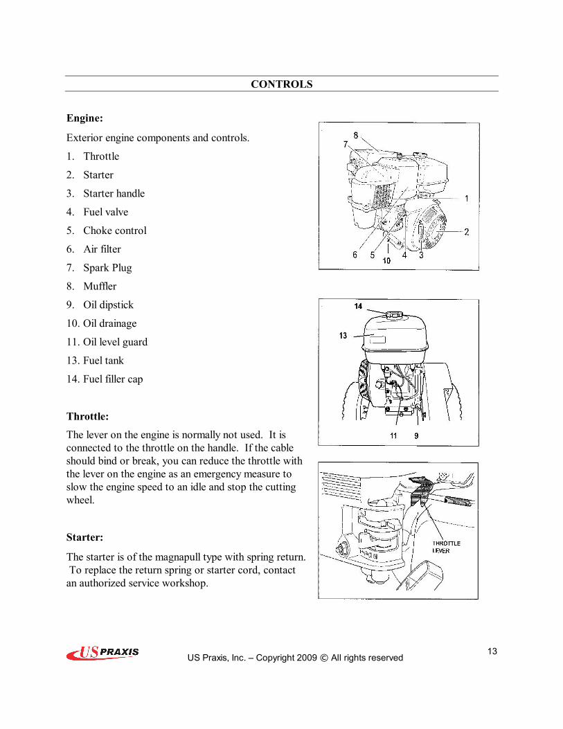
Engine:
Exterior engine components and controls.
1. Throttle
2. Starter
3. Starter handle
4. Fuel valve
5. Choke control
6. Air filter
7. Spark Plug
8. Muffler
9. Oil dipstick
10. Oil drainage
11. Oil level guard
13. Fuel tank
14. Fuel filler cap
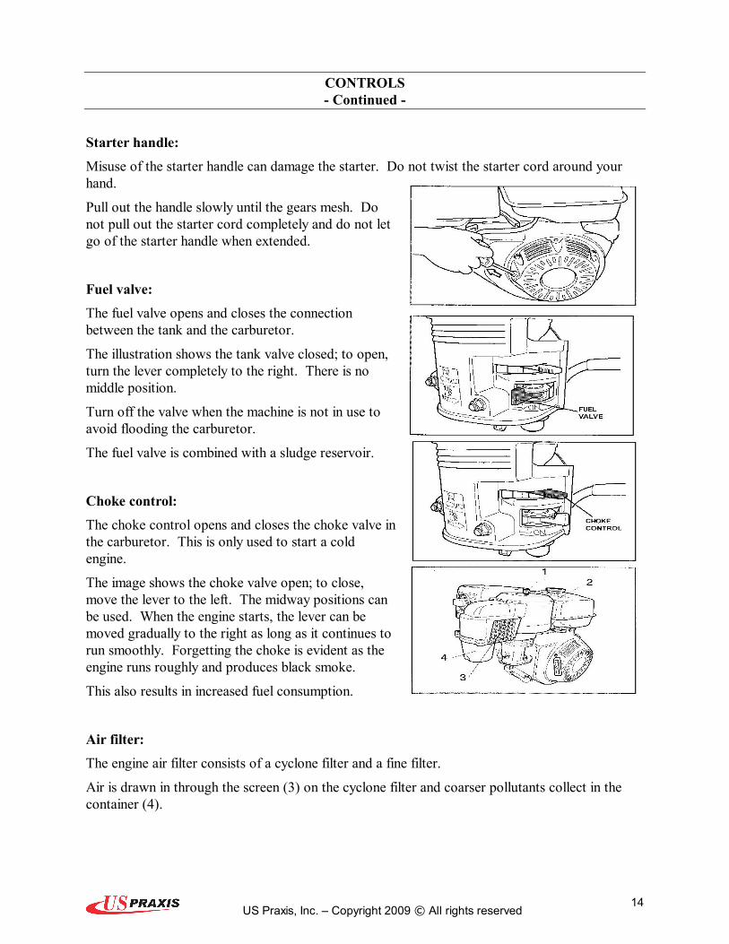
Throttle: The lever on the engine is normally not used. It is connected to the throttle on the handle. If the cable should bind or break, you can reduce the throttle with the lever on the engine as an emergency measure to slow the engine speed to an idle and stop the cutting wheel.
Starter:
The starter is of the magnapull type with spring return. To replace the return spring or starter cord, contact an authorized service workshop.
US Praxis, Inc. – Copyright 2009 © All rights reserved 14
CONTROLS Continued
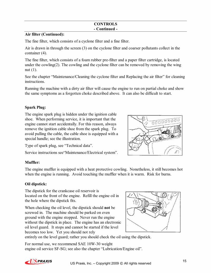
Starter handle: Misuse of the starter handle can damage the starter. Do not twist the starter cord around your hand.
Pull out the handle slowly until the gears mesh. Do not pull out the starter cord completely and do not let go of the starter handle when extended.
Fuel valve: The fuel valve opens and closes the connection between the tank and the carburetor.
The illustration shows the tank valve closed; to open, turn the lever completely to the right. There is no middle position.
Turn off the valve when the machine is not in use to avoid flooding the carburetor.
The fuel valve is combined with a sludge reservoir.
Choke control: The choke control opens and closes the choke valve in the carburetor. This is only used to start a cold engine.
The image shows the choke valve open; to close, move the lever to the left. The midway positions can be used. When the engine starts, the lever can be moved gradually to the right as long as it continues to run smoothly. Forgetting the choke is evident as the engine runs roughly and produces black smoke.
This also results in increased fuel consumption.
Air filter: The engine air filter consists of a cyclone filter and a fine filter.
Air is drawn in through the screen (3) on the cyclone filter and coarser pollutants collect in the container (4).
US Praxis, Inc. – Copyright 2009 © All rights reserved 15
CONTROLS Continued
Air filter (Continued): The fine filter, which consists of a cyclone filter and a fine filter.
Air is drawn in through the screen (3) on the cyclone filter and coarser pollutants collect in the container (4).
The fine filter, which consists of a foam rubber prefilter and a paper filter cartridge, is located under the cowling(2). The cowling and the cyclone filter can be removed by removing the wing nut (1).
See the chapter “Maintenance/Cleaning the cyclone filter and Replacing the air filter” for cleaning instructions.
Running the machine with a dirty air filter will cause the engine to run on partial choke and show the same symptoms as a forgotten choke described above. It can also be difficult to start.
Spark Plug: The engine spark plug is hidden under the ignition cable shoe. When performing service, it is important that the engine cannot start accidentally. For this reason, always remove the ignition cable shoe from the spark plug. To avoid pulling the cable, the cable shoe is equipped with a special handle; see the illustration.
Type of spark plug, see “Technical data”.
Service instructions see“Maintenance/Electrical system”.
Muffler: The engine muffler is equipped with a heat protective cowling. Nonetheless, it still becomes hot when the engine is running. Avoid touching the muffler when it is warm. Risk for burns.
Oil dipstick: The dipstick for the crankcase oil reservoir is located on the front of the engine. Refill the engine oil in the hole where the dipstick fits.
When checking the oil level, the dipstick should not be screwed in. The machine should be parked on even ground with the engine stopped. Never run the engine without the dipstick in place. The engine has an electronic oil level guard. It stops and cannot be started if the level becomes too low. Yet you should not rely entirely on the level guard; rather you should check the oil using the dipstick.
For normal use, we recommend SAE 10W30 weight engine oil service SFSG; see also the chapter “Lubrication/Engine oil”.

US Praxis, Inc. – Copyright 2009 © All rights reserved 16
CONTROLS Continued
Oil drainage: The drainage screw (5) for the crankcase oil reservoir is located on the back of the engine.
IMPORTANT INFORMATION Used engine oil is a health hazard and legislation prohibits disposal on the ground or in nature; it should always be disposed of at a workshop or appropriate disposal location. Avoid skin contact; wash with soap and water in case of spills.
Fuel tank: Underneath the tank, there is a fuel filter combined with a fuel valve. The tank volume is 1.72 Gal. (6.5 liters)
Fueling: Read the safety instructions before fueling. Keep the fuel and fuel tank clean. Avoid filling the machine with dirty fuel. Make sure the fuel cap is properly tightened and the gasket is not damaged, particularly before washing the machine. Use unleaded gasoline with minimum 86 octane rating. Never use gasoline mixed with twocycle oil. For ethanol and methanol fuel, the following applies: Maximum allowable ethanol 10% (volume). Maximum allowable methanol 5% (volume). Maximum allowable MTBE (Methyl Tertiary Butyl Ether) 15% (volume). If the engine “bolts” at normal load it can be damaged. Change the fuel. If this does not help, contact an authorized service workshop. Do not fill the tank completely; leave space for the fuel to expand as it warms up.
Gasoline Is highly flammable. Observe caution and fill the tank outdoors. (See the safety instructions.

US Praxis, Inc. – Copyright 2009 © All rights reserved 17
CONTROLS Continued
Centrifugal clutch: The engine is equipped with a centrifugal clutch that is connected to the crankshaft. When the engine speed increases, the drive for cutting wheel engages automatically. The centrifugal clutch is maintenancefree; it is not possible for the user to make adjustments.
Throttle: The lever controls engine speed. With the lever down, the engine runs at idle and functions as start position. When the engine speed increases, the centrifugal clutch drive automatically engages the cutting wheel.
Brake: The lever activates a disk brake on the left wheel when it is pulled backwards. The brake should always be activated when operating the grinder, when it is parked and when it is being transported.
NEVER operate a machine with a defective brake.
US Praxis, Inc. – Copyright 2009 © All rights reserved 18
OPERATING THE MACHINE
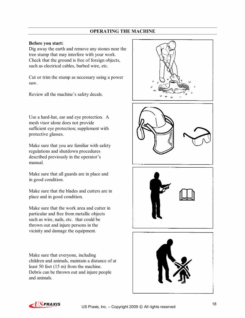
Before you start: Dig away the earth and remove any stones near the tree stump that may interfere with your work. Check that the ground is free of foreign objects, such as electrical cables, barbed wire, etc.
Cut or trim the stump as necessary using a power saw.
Review all the machine’s safety decals.
Use a hardhat, ear and eye protection. A mesh visor alone does not provide sufficient eye protection; supplement with protective glasses.
Make sure that you are familiar with safety regulations and shutdown procedures described previously in the operator’s manual.
Make sure that all guards are in place and in good condition.
Make sure that the blades and cutters are in place and in good condition.
Make sure that the work area and cutter in particular and free from metallic objects such as wire, nails, etc. that could be thrown out and injure persons in the vicinity and damage the equipment.
Make sure that everyone, including children and animals, maintain a distance of at least 50 feet (15 m) from the machine. Debris can be thrown out and injure people and animals.

US Praxis, Inc. – Copyright 2009 © All rights reserved 19
OPERATING THE MACHINE Continued
Starting the engine: Check that all daily maintenance as described in the maintenance schedule has been performed. Check that there is sufficient fuel in the tank.
Fuel valve: Open the fuel valve. Place the lever all the way to the right.
Choke control: When starting the engine warm, the lever should be in the right position; see the illustration. When starting the engine cold or partially warm, place the lever completely or partly to the left. Move the lever back to the right once the engine starts. When the engine is cold, it may be best to move the lever back in several stages. Find the position where the engine runs smoothly.
Throttle Set the throttle on the handle to the SLOW (START)/DISENGAGE position.

US Praxis, Inc. – Copyright 2009 © All rights reserved 20
OPERATING THE MACHINE Continued
Safety presence grip bar Hold in the safety presence grip bar against the handle.
Starter handle: The dead man’s grip must be pressed in when starting the engine.
Misuse of the starter handle can damage the starter. DO NOT twist the starter cord around your hand, Pull out the handle slowly until the gears mesh. Then give a sharp pull on the starter handle. DO NOT pull out the starter cord completely and DO NOT let go of the starter handle when extended.
Throttle Keep the throttle at idle. When the throttle is increased, the cutting wheel will begin rotating.

US Praxis, Inc. – Copyright 2009 © All rights reserved 21
OPERATING THE MACHINE Continued
1. Place stump machine into position with cutting blade near the fronttop edge of stump.
2. Set brake to lock position.
3. Set throttle to (START) DISENGAGE position.
4. Start engine.
5. Allow engine to warm up at idle for two minutes.
6. Move throttle up to the ENGAGE position (this will engage the cutting blade rotation).
7. Swing the cutting blade to one side, then lower it approximately 1/2" to 1" into the fronttop corner of the stump. Swing the cutting blade back and forth, lowering the cutting blade approximately 1/2" to 1" before each sweep, until you have removed the front portion of the stump to ground level.
8. Raise cutting blade until center of cutting blade is just above top of stump.
9. With the cutting blade off to one side, advance the machine horizontally by releasing and resetting the brake. Advance the machine forward to engage the cutting blade into the stump so that when swept across the stump it will remove 1/2" to 1" of stump with each sweep.
10. Sweep the cutting blade across the stump, cutting away 1/2" to 1" of stump.
11. Advance cutting blade 1/2" to 1", and sweep across stump in opposite direction.
12. Continue sweeping cutting blade left and right across stump, advancing it before each sweep, cutting 1/2" to 1" depth of stump with each sweep.
13. Continue cutting until top level of stump is all removed, making sure not to cut stump deeper than ground level during this first stage.
OPERATING THE MACHINE

US Praxis, Inc. – Copyright 2009 © All rights reserved 22
Continued
14. Turn throttle to the (START)DISENGAGE position, wait ten seconds for blade to stop rotating then release brake and retract machine from stump.
15. Pull machine away from stump, and rake chips away from stump.
16. Place stump machine into position with cutting blade near the fronttop edge of the stump.
17. Set brake to lock position.
18. Move throttle up to the ENGAGE position.
19. Complete cutting stump by repeating step 12 again and again until entire stump is cut to desired depth.
20. Stop the machine.
Normal shutdown Throttle Set the throttle to SLOW/DISENGAGE.
If the engine has been running full out, let it run easily for about 30 seconds to one minute at low speed.
DO NOT let front of unit touch ground until you are sure cutting wheel has stopped turning.
A rotating cutting blade is very DANGEROUS! Stay at the operating position and be sure that the blade comes to a complete stop before doing anything else.

US Praxis, Inc. – Copyright 2009 © All rights reserved 23
OPERATING THE MACHINE Continued
Brake Activate the brake by pulling the lever.
Fuel valve Close the fuel valve. Turn the lever all the way to the left (see illustration).
Release the safety presence bar.
Wait until the blade stops.
Make sure that the blade is resting against the ground and has stopped completely before doing anything.

US Praxis, Inc. – Copyright 2009 © All rights reserved 24
MAINTENANCE
Maintenance schedule The following is a list of maintenance procedures that MUST be performed on the machine. For those points not described in this manual, call your dealer or the manufacturer directly.
1)First change after 20 hours. 2) In dusty conditions maintenance is required at shorter intervals. 3)Before each use. 4)Performed by authorized service workshop. 5)Performed every second year. 6)Grease every 4 hours.
No service operations may be performed on the engine or unit unless: The engine is stopped. The ignition cable has been removed from the spark plug. The machine is securely parked where it will not tip or begin rolling.

US Praxis, Inc. – Copyright 2009 © All rights reserved 25
MAINTENANCE Continued
Cleaning the cyclone filter The cyclone filter collects the largest contaminant particles, which collect in the container. When you can see a layer of dirt at the bottom of the container, the cyclone housing (4), air channels and air intake screen (3) must be cleaned.
Remove the three screws holding the cyclone housing. Remove the housing with the air intake screen and remove the air channels.
The air channels may remain in the upper portion or follow along with the housing when removed.
Clean the components. Use water, detergent and a washingup brush. Dry carefully.
Refit the components. Place the air channels in the cyclone housing. Insert cyclone housing into position and make sure it fits in the upper portion. DO NOT use force; rater coax it into place before fitting the screws.
IMPORTANT INFORMATION Exercise care when reassembling to avoid damaging anything. Make sure when mounting that the air intake screen fits exactly in its guide in the upper portion. Make sure the air channel ends up in the proper position.
MAINTENANCE

US Praxis, Inc. – Copyright 2009 © All rights reserved 26
Continued
Replacing the air filter If the engine seems weak, produces black smoke or runs unevenly, the air filter may be clogged. For this reason, it is important to clean and replace the air filter regularly (see the maintenance schedule for the proper service interval).
Allow the exhaust system to cool before performing service. Risk for burns.
Cleaning/replacement of the air filter is carried out as follows:
1. Undo the wing nut (1) and lift off the cyclone filter with the air filter cowling (2).
2. Remove the foam rubber prefilter and clean using a mild detergent.
Squeeze it dry with a clean cloth.
Soak it with new engine oil. Wind the filter in an absorbent cloth and squeeze out excess oil.
3. Remove the wing nut in the air filter and remove the paper filter. Tap the paper filter against a fixed surface to remove dust. If the paper filter is still dirty or damaged, it MUST be replaced.
IMPORTANT INFORMATION DO NOT use compressed air over 2 bar/30 PSI to clean the paper filter. DO NOT wash the paper filter. DO NOT oil the paper filter.
4. Refit the air filter as follows:
Mount the paper filter in the air filter housing and tighten the wing nut.
5. Refit the prefilter on the paper filter.
6. Refit the cyclone filter with the air filter cowling.
MAINTENANCE
US Praxis, Inc. – Copyright 2009 © All rights reserved 27
Continued
Cleaning the sludge reservoir:
1. Close the fuel valve. 2. Unscrew the sludge reservoir (2). Make
sure not to misplace the oring (1). 3. Clean the reservoir and the owing using a
cleaning solvent and dry carefully. 4. Put the oring in place in its track and
replace the sludge reservoir (2). Make sure not to misplace the oring (1).
5. Turn the fuel valve to ON and check for leaks. If it leaks, replace the oring.
Idle adjustment
Risk for carbon monoxide poisoning. Perform the adjustment outdoors.
1. Start the engine and run it until it reaches normal working temperature.
2. Adjust the throttle to idle position or so that the engine runs at the lowest possible speed.
3. Turn the idle screw (1) so that the engine idles at 12501550 RPM.
4. Increase the idle speed with the throttle and move it right back to idle position. Check engine speed again.
MAINTENANCE

US Praxis, Inc. – Copyright 2009 © All rights reserved 28
Continued
Ignition system:
The engine is equipped with an electronic ignition system. Only the spark plug requires maintenance. For recommended spark plug, see “Technical data”.
IMPORTANT INFORMATION Fitting the wrong spark plug type can damage the engine.
1. Remove the ignition cable shoe and clean around the spark plug.
2. Remove the spark plug with a 3/16" (21mm) spark plug socket wrench.
3. Check the spark plug. Replace the spark plug if the electrodes are burned or if the insulation is cracked or damaged. Clean the spark plug with a steel brush if it is to be reused.
4. Measure the electrode gap with a gapping tool. The gap should be 0.70.8 mm/0.0280.031". Adjust as necessary by bending the side electrode.
5. Reinsert the spark plug, turning by hand to avoid damaging the threads.
IMPORTANT INFORMATION Inadequately tightened spark plugs can caus overheating and damage the engine. Tightening the spark plug too much can damage the threads in the cylinder head.
6. After the spark plug is seated, tighten it using a spark plug wrench so that the washer is compressed. A used spark plug should be turned 1/81/4 of a turn from the seated position. A new spark plug should be turned ½ a turn from the seated position.
7. Replace the ignition cable shoe.
MAINTENANCE

US Praxis, Inc. – Copyright 2009 © All rights reserved 29
Continued
Cutting blade: Among the most critical elements of the Stump Machine is the cutting blade. It is also the most subject to damage and wear. In the course of grinding stumps it not only makes contact with the wood, but also encounters numerous assortments of abrasives and objects in the stump’s environment, such as dirt, stones, and occasionally a large rock or buried scrap.
The loss of and wear of cutting teeth can significantly impair the efficiency and performance of the Stump Machine. Therefore, it is important to make frequent observations of the condition of all of the cutting teeth and replace or sharpen any damaged or worn blade sections.
NOTICE Read all the following instructions before beginning to change cutting blade sections.
1. Clean all dirt from the cutting blade and mounting flanges. 2. Remove all bolts holding cutting blade, (Be
careful not to let a section drop when they become loose).
3. Check each section for cracks. Replace blade section if it is cracked.
4. When replacing cutting blade sections, make sure blade section is placed in alignment with blade rotation.
5. Refer to page of this Manual for proper blade attachment.
Installing new blades: Insert blade section between the blade mounting flanges.
Slide bolt through one side of flange, and through flange on other side. Attach lock washer and nut, tighten securely. (Make sure tow bolts are tightened for each blade section).
MAINTENANCE
US Praxis, Inc. – Copyright 2009 © All rights reserved 30
Continued
Sharpening Cutting Blade Sections: Do not allow the cutting blade to wear too much before sharpening. The cutting blade sections must be removed from the machine before sharpening.
NOTICE Sharpening carbide cutting teeth requires a special process.
US Praxis, Inc. OFFERS A COMPLETE LINE OF SHARPENING ACCESSORIES AND
SHARPENING SERVICES Toll Free: 8883168200
MAINTENANCE

US Praxis, Inc. – Copyright 2009 © All rights reserved 31
Continued
Brake Adjustment For fine adjustment, loosen set screw on side of brake lever knob. Adjust clockwise to tighten brake; adjust counter clockwise to loosen brake. (Wheel should lock completely, tighten set screw). For coarse adjustment, turn adjusting nuts on brake cable fitting at brake cable mount.
Two minute rule The machine may be tipped backward or on its side to facilitate access for cleaning or service, but no longer than 2 minutes. If the machine is held in this position for too long, the engine can be damaged by gasoline draining into the crankcase. Should this happen, perform an extra oil change on the engine over a few revolutions with the starter handle before starting the engine again.
Cleaning and washing Regular cleaning and washing will increase the machine’s life span. Make it a habit to clean the machine directly after use, before the dirt sticks. Check before reusing that the fuel tank lid is properly in place to avoid getting water in the tank. Use caution when using highpressure spray because warning decals, instruction signs and the engine can be damaged. Do not exceed 70 bar/1000 PSI water pressure when cleaning. Lubricate the machine after cleaning. This is particularly important if the machine is to be stored.
Lubricating Bearings Cutting blade bearings should be greased after every 10 hours of operation. Lubricate two fittings (one on each cutting blade bearing).
NOTICE Pump grease in slowly and carefully to prevent damage to the bearing seals. Use extreme caution when using a high pressure or high volume grease gun.
MAINTENANCE Continued

US Praxis, Inc. – Copyright 2009 © All rights reserved 32
Drive Belts: The drive system of the stump machine is composed of a 3V banded Vbelt. The stump machine’s Vbelt tension should be checked daily.
Before beginning to check or adjust belt: shutdown the machine, be sure that all moving parts have come to a complete stop. Extreme caution must be used to avoid death or serious injury. Stay clear of belts, pulley, clutch and cutting blade when they are moving.
NOTICE To extend belt life, proper tension must be maintained. A loose belt will cause excessive cutting blade slippage and belt failure. A belt that is too tight can cause bearing, shaft and belt failure.
To adjust belt tension, loosen the 2 bolts behind clutch. Also loosen the 4 engine mounting bolts. Turn square head adjusting bolt on frame clockwise to tighten belt, counter clockwise to loosen belt. (Make sure to tighten all 6 bolts after proper belt adjustment is achieved). To check belt tension, you should be able to depress the belt down about 1/4 3/8" (610mm) from the original position.
TROUBLE SHOOTING

US Praxis, Inc. – Copyright 2009 © All rights reserved 33
Symptom Cause Action The engine won’t start User error
Fuel system
Spark plug
No spark after checking spark plug
Low compression
Fuel valve closed. Choke valve open. Engine switch in OFF position.
Fuel tank empty. Machine stored without observing proper procedure from chapter “Storage/Winter storage”.
Contamination, water or ice in fuel system.
Carburetor problems.
Wrong spark plug type. Buildup on electrodes. Short circuit. Gasoline or oil on the spark plug.
Faulty engine switch, cable or ignition.
Serious interior engine damage or faulty valves.
Open the fuel valve. Close the choke with cold engine. Turn engine switch to ON.
Fill with fuel. Clean tank, sludge reservoir and empty carburetor. Fill the tank with fresh fuel.
Clean tank, sludge reservoir, fuel lines and carburetor Fill the tank with fresh fuel.
Replace the spark plug. Check electrode gap and clean or replace spark plug. Clean the spark plug. Air the engine out. Start with full throttle.
Contact authorized service workshop.
Contact an authorized service workshop.
TROUBLE SHOOTING Continued

US Praxis, Inc. – Copyright 2009 © All rights reserved 34
Symptom Cause Action Engine is gutless or runs unevenly Air filter
Fuel system
(Blue exhaust) (Voluminous blue white exhaust)
(Black exhaust)
Ignition system
Clogged air filter.
Machine stored without observing proper procedure from chapter “Storage/Winter storage”.
Tank filled with 2cycle mixed oil. Tank filled with diesel.
Choke left on. Clogged air filter. Carburetor problems.
Wrong spark plug type. Buildup on electrodes. Short circuit. Faulty ignition unit.
Clean or replace the air filter.
Clean tank, sludge reservoir and empty carburetor. Fill the tank with proper fuel. Fill the tank with proper fuel. Clean tank, sludge reservoir and empty carburetor. Fill the tank with proper fuel. Open choke valve. Clean or replace the air filter. Contact an authorized service workshop.
Replace the spark plug. Check electrode gap and clean or replace spark plug. Contact an authorized service workshop.
TROUBLE SHOOTING Continued

US Praxis, Inc. – Copyright 2009 © All rights reserved 35
Problem Possible solutions Belt coming off.
Belt engages late or slips.
Belt not staying tight after adjustment.
The cutting wheel does not rotate.
The cutting wheel continues to rotate.
The parking brake is slipping.
1. Pulleys not aligned. 2. Belt tension is insufficient. Adjust belt tension.
1. Tighten the belt as described in the operator’s manual. 2. Reduce cutting depth.
1. Check for damage on the axle, pulley or key. Make sure that the setscrews are properly tightened. 2. Replace damaged parts.
1. Engine speed is insufficient to activate the centrifugal clutch. Make sure the throttle cable is working properly. 2. Belt tension is insufficient. Adjust belt tension. 3. Clutch is worn replace shoes and springs, and/or clutch bearings.
1. Check that the throttle is disconnected. 2. Check for damage on the throttle cable. 3. Check that the throttle cable is properly mounted on the throttle valve. 4. The engine speed is not under 1000 rpm, which is required to disengage the centrifugal clutch. 5. Inspect springs on clutch shoes. If tension on clutch shoes is not enough to pull shoes back, replace springs and clutch shoes.
1. Adjust the brake tension in the manner described in the operator’s manual.
2. Check for damage on the brake rod or lever. 3. Check for wear on the brake pads. Replace as necessary.
STORAGE & TECHNICAL DATA
Winter storage

US Praxis, Inc. – Copyright 2009 © All rights reserved 36
At the end of the season, the machine should be readied for storage (or if it will not be in use for longer than 30 days). Fuel allowed to stand for long periods of time (30 days or more) can leave sticky residues that can plug the carburetor and disrupt engine function. Fuel stabilizers are an acceptable option to guard against sticky residue build up during storage.
If alkylate gasoline (Aspen) is used, stabilizers are unnecessary because this fuel is stable. However, you should avoid switching between regular and alkylate gasoline as sensitive rubber components can harden. Add stabilizer to the fuel in the tank or in the storage container.
Always use the mixing ratios specified by the manufacturer of the stabilizer. Run the engine for at least 10 minutes after add in the stabilizer so that it reaches the carburetor. DO NOT empty the fuel tank and the carburetor if you have added stabilizer.
NEVER store an engine with fuel in the tank indoors or in poorly ventilated spaces where fuel vapor can come in contact with open flame, sparks or a pilot light such as in a boiler, hot water tank, clothing drier, etc. Handle the fuel with caution. It is very flammable and careless use can cause serious damage to person and property. Drain the fuel into an approved container outdoors and far away from open flame. NEVER use gasoline for cleaning. Use a degreaser and warm water instead.
Service When ordering spare parts, please specify the purchase year, model, type, and serial number. Always use genuine Praxis parts.
An annual checkup at an authorized service workshop is a good way to ensure that your machine performs its best the following season.
To ready the machine for storage, follow these steps: 1. Clean the machine carefully, particularly the chasses and working equipment. Touch up damage to the paint to prevent rust.
2. Inspect the machine for worn or damaged parts and tighten any nuts or screws that may have become loose.
3. Change the engine oil; dispose of properly.
4. Open the fuel valve. Empty the fuel tank (1) and the carburetor (2).
STORAGE & TECHNICAL DATA Continued

US Praxis, Inc. – Copyright 2009 © All rights reserved 37
5. Close the fuel valve.
6. Remove the spark plug and pour about a tablespoon of engine oil in the cylinder. Turn over the engine so that the oil is evenly distributed and then refit the spark plug. Put the engine in the compression phase where the triangle mark on the sleeve of the starter is aligned with the upper hole in the starter. Note: Compression phase occurs every second revolution
7. Lubricate all grease nipples, joints and cables as described in the chapter
“Lubrication/Lubrication schedule”.
8. Store the machine in a clean, dry place and cover it for extra protection.
9. Cover the blade and cutters with a thin coat of oil to avoid rust.
SPECIFICATIONS:
Model Engine Power Idling speed Spark plug
Fuel tank volume Tires Brake Drive Belt Clutch Cutters
Cutting depth Length Width Height Weight
PRX90 Honda GX270QXC9 9 hp 12501550 RPM NK BPR6ES DENSO W20EPRU 6 liters/1.60 US Gal 4.10 4 (pneumatic) Disk Lever activated Direct 3V Centrifugal clutch 12 cutters with tungsten carbide tips Approx 12" (30.48 cm) 71 (180 cm) 26.5 (67cm) 40" (102 cm) 200 lbs. (90 kg)
PRX130 Honda GX390QXC9 13 hp 12501550 RPM NK BPR6ES DENSO W20EPRU 6.5 liters/1.72 US Gal 13 x 5.00 6 (pneumatic) Disk Lever activated Direct 3V Centrifugal clutch 12 cutters with tungsten carbide tips Approx 12" (30.48 cm) 76" (193 cm) 29.5 (75 cm) 42" (107 cm) 240 lbs. (109 kg)
STORAGE & TECHNICAL DATA Continued
Service Journal: Action Date, stamp, signature

US Praxis, Inc. – Copyright 2009 © All rights reserved 38
Delivery service 1. Break the packaging and make sure the machine has not been
damaged in transport. 2. Where applicable, assembly accompanying components. 3. Check that the machine design corresponds to the
customer order. 4. Check that the right amount of oil is in the engine and
transmission. 5. Check and adjust air pressure in the tires. (25 psi max.) 6. Check that the working equipment is properly set. 8. Check that the drive pulleys and sprockets are aligned. 9. Lubricate the machine as described in the lubrication schedule. 10. Fill the fuel tank and start the engine. 11. Check that the machine and working equipment do not
move in neutral. 12. Check that all operating instruments. 13. Check decals and information attached to the unit. 14. Check the engine speed (RPM), see Technical Data. 15. Check for leakage. 16. Inform the customer about:
The need and advantages of following the service schedule. The need and advantages of leaving the machine for service Every 300 hours. The effects of service and maintaining a service journal on the Machine’s resale value.
17. Fill in the sales papers, etc.
After the first 20 hours 1. Change the engine oil. 2. Change oil in reduction gear, where applicable. 3. Check that belts and chains are properly adjusted. 4. Tighten screws and nuts.
STORAGE & TECHNICAL DATA Continued
Service Journal (Continued): Action Date, stamp, signature

US Praxis, Inc. – Copyright 2009 © All rights reserved 39
PARTS LIST
PRX90 & PRX130 Chassis and Engine Assembly

US Praxis, Inc. – Copyright 2009 © All rights reserved 40
CHASSE AND ENGINE ASSEMBLY

US Praxis, Inc. – Copyright 2009 © All rights reserved 41
MODELS PRX90 & PRX130
Ref No. Part No. Description QTY 1 GX 270QXC Honda 9hp Cyclone with Muffler Cap 1 1 GX 390QXC Honda 13hp Cyclone with Muffler Cap 1 2 FC 4509 Frame 9hp 1 2 FC 45013 Frame 13hp 1 3 96005 5/16 Flat Washer 4 4 33893 3/8 Lock Washer 4 5 95813 3/816 Nut 4 6 21819 Carriage Bolt 3/816 x 1 1/2 4 7 FC 4519 Axle 9hp 1 7 FC 45113 Axle 13hp 1 8 FC 452 Inner Belt Guard 1 9 17055 5/1624 x 1 Bolt 2 10 33620 5/16 Lock Washer 2 11 96005 5/16 Flat Washer 8 12 95105 3/816 x 1 Bolt 1 13 33893 3/8 Lock Washer 1 14 96005 5/16 Flat Washer 1 15 95813 3/816 Nut 1 16 37820A Spacer 1 17 37820B Spacer 1 18 95053 5/1618 x 3/4 Bolt 1 19 33620 5/16 Lock Washer 1 20 95812 5/1618 Nut 1 21 26076 Square 3/816 x 3 Bolt 1 22 95813 3/816 Nut 2 23 30025002501750 1/4 Key 1 24 VRVC201 3V Sheave with Bushing 1 24 VC 304 Front Shaft Pulley (Prior to 2004) 1 25 VRVC200 3V Clutch 1 25 VC 301 Clutch (Prior to 2004) 1 26 17159 7/1620 x 1 1/2 Bolt 1 27 33894 7/16 Lock Washer 1 28 96006 3/8 Flat Washer 1 29 33860 7/16 USS Flat Washer 1 30 VRVC203 3V Banded Belt 1 30 VC 305 Banded Belt (Prior to 2004) 1 31 FC 453 Outer Belt Guard 1
PRX90 & PRX130 Handle Assembly

US Praxis, Inc. – Copyright 2009 © All rights reserved 42
HANDLE ASSEMBLY MODELS PRX90 & PRX130

US Praxis, Inc. – Copyright 2009 © All rights reserved 43
Ref No. Part No. Description QTY 1 FC 349 Operator Handle 1 2 FC 350 Operator Presence Safety Handle 1 3 90040 5/1618 Lock Nut 4 4 95063 5/1618 x 2 1/2 Bolt 2 5 VC 350 Stainless Steel Return Spring 1 6 VC 351 Sealed Plunger 1 7 28957 1024 x 1/2 Screw 2 8 37014 Nylock 1024 2 9 VC 352 Electrical Wiring 1 10 VC 306 Throttle Cable with Knob 1 11 VC 306 Throttle Cable with Knob 1 12 28794 632 x 3/8 Screw 2 13 37010 Nylock 632 2 14 VC 307 Brake Lever 1 15 95063 5/1618 x 2 1/2 Bolt 2 16 33620 5/16 Lock Washer 2 17 95812 5/1618 Nut 2 18 VC 308 Brake Cable 1 19 95159 7/1614 x 1 1/2 Bolt 4 20 96006 3/8 Flat Washer 8 21 33894 7/16 Lock Washer 4 22 95814 7/1614 Nut 4 23 9600 Rubber Grommet 2 24 FC 348 Operator Handle Gasket 1
PRX90 & PRX130 Blade and Shaft Assembly

US Praxis, Inc. – Copyright 2009 © All rights reserved 44
BLADE AND SHAFT ASSEMBLY MODELS PRX90 & PRX130

US Praxis, Inc. – Copyright 2009 © All rights reserved 45
Ref No. Part No. Description QTY 1 FC 302 Complete Shaft Assembly (Shaft, Flanges, Bearings) 1 2 VC 302 Pillow Block Bearings each 2 3 18838 3/824 x 1 1/2 Bolt 4 4 98025 3/8 Thick Washer 8 5 33893 3/8 Lock Washer 4 6 36456 3/824 Nut 4 7 FC 302A Shaft with Key 1 8 FC 302B Shaft Flange 1 9 15109 3/816 x 1 1/2 Bolt 8 10 33893 3/8 Lock Washer 8 11 95813 3/816 Nut 8 12 VC 300 Complete Set of Fasteners Blade (8 Bolts, Locks, Nuts) 1 13 PRX 1000 Stump Grinding Quadrublade 1
PRX 2000 Trencher Grinding Quadrublade 1 PRX 250 1/4 section Stump Grinding Quadrublade 1 PRX 500 1/4 section Trencher Grinding Quadrublade 1 PRX4000 SixPack Tote of Grinding Quadrublades 1
PRX90 & PRX130 Brake and Wheel Assembly

US Praxis, Inc. – Copyright 2009 © All rights reserved 46

US Praxis, Inc. – Copyright 2009 © All rights reserved 47
BRAKE AND WHEEL ASSEMBLY MODELS PRX90 & PRX130
Ref No. Part No. Description QTY 1 VC 3259 Tire without Hub 9hp 2 1 VC 32513 Tire without Hub 13hp 2 2 VC 325H9 Tire Complete with Hub 9hp 1 2 VC 325H13 Tire Complete with Hub 13hp 1 3 VC 325B9 Tire Complete with Brake Hub 9hp 1 3 VC 325B13 Tire Complete with Brake Hub 13hp 1 4 VC 396 Wheel Bearing 4 5 VC 383 Set Collar 2 6 VC 395 Hub 1 7 VC 397 Hub with Brake Disk 1
PRX90 & PRX130 Chassis and Flap Assembly

US Praxis, Inc. – Copyright 2009 © All rights reserved 48

US Praxis, Inc. – Copyright 2009 © All rights reserved 49
CHASSE AND FLAP ASSEMBLY MODELS PRX90 & PRX130
Ref No. Part No. Description QTY 1 FC 318A9 Rear Flap 9hp 1 1 FC 318A13 Rear Flap 13hp 1 2 FC 318B9 Rear Flap Support 9hp 1 2 FC 318B13 Rear Flap Support 13hp 1 3 95055 5/1618 x 1 Bolt 6 4 33620 5/16 Lock Washer 6 5 95812 5/1618 Nut 6 6 FC 319A Right Side Flap 1 7 FC 319B Right Side Flap Support 1 8 95055 5/1618 x 1 Bolt 5 9 33620 5/16 Lock Washer 5 10 95812 5/1618 Nut 5 11 FC 320A Left Side Flap 1 12 FC 320B Left Side Flap Support 1 13 95053 5/1618 x 3/4 Bolt 4 14 33620 5/16 Lock Washer 4 15 95812 5/1618 Nut 4 16 FC 321A9 Small Flap 9hp 1 16 FC 321A13 Small Flap 13hp 1 17 FC 321B9 Small Flap Support 9hp 1 17 FC 321B13 Small Flap Support 13hp 1 18 95053 5/1618 x 3/4 Bolt 2 19 33620 5/16 Lock Washer 2 20 95812 5/1618 Nut 2