Embed Size (px)
Citation preview

System z10
Processor Resource/Systems ManagerPlanning GuideSB10-7153-04
Level 04b, April 2011
���


System z10
Processor Resource/Systems ManagerPlanning GuideSB10-7153-04
Level 04b, April 2011
���

NoteBefore using this information and the product it supports, read the information in “Safety” on pagexi, Appendix D, “Notices,” on page 231, and IBM Systems Environmental Notices and User Guide,Z125-5823.
This edition, SB10-7153-04, applies to the IBM System z10 Enterprise Class (z10 EC) and System z10 BusinessClass (z10 BC) servers. This edition replaces SB10–7153–03. Technical changes to the text are indicated by avertical bar (|) to the left of the change.
There might be a newer version of this document in a PDF file available on Resource Link. Go tohttp://www.ibm.com/servers/resourcelink and click Library on the navigation bar. A newer version is indicated by alowercase, alphabetic letter following the form number suffix (for example: 00a, 00b, 01a, 01b).
© Copyright IBM Corporation 2008, 2010.US Government Users Restricted Rights – Use, duplication or disclosure restricted by GSA ADP Schedule Contractwith IBM Corp.
Level 04b, April 2011
||

Contents
Figures . . . . . . . . . . . . . . . . . . . . . . . . . . . vii
Tables . . . . . . . . . . . . . . . . . . . . . . . . . . . . ix
Safety . . . . . . . . . . . . . . . . . . . . . . . . . . . . xiSafety notices . . . . . . . . . . . . . . . . . . . . . . . . . xi
World trade safety information . . . . . . . . . . . . . . . . . . xiLaser safety information . . . . . . . . . . . . . . . . . . . . . . xi
Laser compliance . . . . . . . . . . . . . . . . . . . . . . . xi
About this publication . . . . . . . . . . . . . . . . . . . . . xiiiWhat is included in this publication . . . . . . . . . . . . . . . . . xivRelated publications . . . . . . . . . . . . . . . . . . . . . . . xv
z/Architecture . . . . . . . . . . . . . . . . . . . . . . . . xvEnterprise Systems Architecture/390 (ESA/390) . . . . . . . . . . . . xvHardware . . . . . . . . . . . . . . . . . . . . . . . . . . xvSoftware . . . . . . . . . . . . . . . . . . . . . . . . . . xv
How to send your comments . . . . . . . . . . . . . . . . . . . xvii
Summary of changes . . . . . . . . . . . . . . . . . . . . . . xix
Chapter 1. Introduction to logical partitions . . . . . . . . . . . . . . 1Overview . . . . . . . . . . . . . . . . . . . . . . . . . . . 2Prerequisites for operation . . . . . . . . . . . . . . . . . . . . . 2
PR/SM . . . . . . . . . . . . . . . . . . . . . . . . . . . 2System z Parallel Sysplex support . . . . . . . . . . . . . . . . . 5Guest coupling simulation . . . . . . . . . . . . . . . . . . . . 6Control program support in a logical partition . . . . . . . . . . . . . 6Input/Output Configuration Program (IOCP) support . . . . . . . . . . 15Hardware support . . . . . . . . . . . . . . . . . . . . . . . 15Operator training . . . . . . . . . . . . . . . . . . . . . . . 15
Logical partitions . . . . . . . . . . . . . . . . . . . . . . . . 16Characteristics . . . . . . . . . . . . . . . . . . . . . . . . 16Potential applications . . . . . . . . . . . . . . . . . . . . . 19
Compatibility and migration considerations. . . . . . . . . . . . . . . 21Device numbers . . . . . . . . . . . . . . . . . . . . . . . 21Multiple Subchannel Sets (MSS) . . . . . . . . . . . . . . . . . 21Control programs . . . . . . . . . . . . . . . . . . . . . . . 21CPU IDs and CPU addresses . . . . . . . . . . . . . . . . . . 23
HSA allocation . . . . . . . . . . . . . . . . . . . . . . . . . 25TOD clock processing . . . . . . . . . . . . . . . . . . . . . . 25
No sysplex timer attached and Server Time Protocol not enabled . . . . . 25Sysplex timer attached . . . . . . . . . . . . . . . . . . . . . 25Server Time Protocol enabled . . . . . . . . . . . . . . . . . . 26Sysplex testing without a Sysplex Timer and Server Time Protocol not
enabled. . . . . . . . . . . . . . . . . . . . . . . . . . 26Synchronized Time Source and the coupling facility . . . . . . . . . . 26Extended TOD-clock facility . . . . . . . . . . . . . . . . . . . 27Clock Comparator on Shared Processors . . . . . . . . . . . . . . 27
Chapter 2. Planning considerations . . . . . . . . . . . . . . . . 29Overview . . . . . . . . . . . . . . . . . . . . . . . . . . . 31Planning the I/O configuration . . . . . . . . . . . . . . . . . . . 31
Level 04b, April 2011
© Copyright IBM Corp. 2008, 2010 iii

Planning considerations . . . . . . . . . . . . . . . . . . . . 31Maximum number of logical partitions . . . . . . . . . . . . . . . 33Managing logical paths for ESCON and FICON channels . . . . . . . . 35Managing the establishment of logical paths . . . . . . . . . . . . . 39Shared channel overview . . . . . . . . . . . . . . . . . . . . 49Unshared ESCON or FICON channel recommendations. . . . . . . . . 55Dynamically managed CHPIDs . . . . . . . . . . . . . . . . . . 55IOCP coding specifications . . . . . . . . . . . . . . . . . . . 56
Coupling facility planning considerations . . . . . . . . . . . . . . . 67Test or migration coupling configuration . . . . . . . . . . . . . . . 67Production coupling facility configuration . . . . . . . . . . . . . . 68Internal Coupling Facility (ICF) . . . . . . . . . . . . . . . . . . 69System-managed coupling facility structure duplexing. . . . . . . . . . 71Single CPC software availability sysplex . . . . . . . . . . . . . . 72Coupling facility nonvolatility . . . . . . . . . . . . . . . . . . . 72Coupling facility mode setting . . . . . . . . . . . . . . . . . . 73Coupling facility LP definition considerations . . . . . . . . . . . . . 73Coupling facility LP storage planning considerations . . . . . . . . . . 74Dump space allocation in a coupling facility . . . . . . . . . . . . . 75Coupling facility LP activation considerations . . . . . . . . . . . . . 75Coupling facility shutdown considerations . . . . . . . . . . . . . . 76Coupling facility LP operation considerations . . . . . . . . . . . . . 76Coupling facility control code commands . . . . . . . . . . . . . . 76Coupling facility level (CFLEVEL) considerations . . . . . . . . . . . 77Coupling Facility Resource Management (CFRM) policy considerations . . . 80Coupling facility channels . . . . . . . . . . . . . . . . . . . . 81
Considerations when migrating from ICMF to ICs . . . . . . . . . . . . 86Linux operating system planning considerations . . . . . . . . . . . . . 86
Integrated Facility for Linux (IFL) . . . . . . . . . . . . . . . . . 86z/VM utilizing IFL features . . . . . . . . . . . . . . . . . . . . 87
IBM System z10 Application Assist Processor (zAAP). . . . . . . . . . . 87IBM System z10 Integrated Information Processor (zIIP) . . . . . . . . . 88Concurrent patch . . . . . . . . . . . . . . . . . . . . . . . . 89CFCC enhanced patch apply. . . . . . . . . . . . . . . . . . . . 89Dynamic capacity upgrade on demand . . . . . . . . . . . . . . . . 90
PR/SM shared partitions . . . . . . . . . . . . . . . . . . . . 90Mixed shared and dedicated PR/SM partitions . . . . . . . . . . . . 91Multiple dedicated PR/SM partitions . . . . . . . . . . . . . . . . 92Shared Internal Coupling Facility . . . . . . . . . . . . . . . . . 92
Dynamic capacity upgrade on demand limitations . . . . . . . . . . . . 93Concurrent Memory Upgrade. . . . . . . . . . . . . . . . . . . . 94Capacity Backup Upgrade (CBU) capability . . . . . . . . . . . . . . 94Enhanced Book Availability . . . . . . . . . . . . . . . . . . . . 95
Preparing for Enhanced Book Availability . . . . . . . . . . . . . . 95Customer Initiated Upgrade (CIU) . . . . . . . . . . . . . . . . . . 97Concurrent Processor Unit conversion . . . . . . . . . . . . . . . . 98Planning for nondisruptive install of crypto features . . . . . . . . . . . 98
Chapter 3. Determining the characteristics of logical partitions . . . . . 99Planning overview . . . . . . . . . . . . . . . . . . . . . . . 102
Performance considerations. . . . . . . . . . . . . . . . . . . 102Recovery considerations . . . . . . . . . . . . . . . . . . . . 103
Determining the characteristics . . . . . . . . . . . . . . . . . . 103Control program support . . . . . . . . . . . . . . . . . . . . 103IOCDS requirements . . . . . . . . . . . . . . . . . . . . . 104Logical partition identifier . . . . . . . . . . . . . . . . . . . . 104
Level 04b, April 2011
iv PR/SM Planning Guide

Mode of operation . . . . . . . . . . . . . . . . . . . . . . 105Storage configurations. . . . . . . . . . . . . . . . . . . . . 105Central storage . . . . . . . . . . . . . . . . . . . . . . . 106Expanded storage . . . . . . . . . . . . . . . . . . . . . . 108Dynamic storage reconfiguration . . . . . . . . . . . . . . . . . 110Number of central processors . . . . . . . . . . . . . . . . . . 120Central processor recommendations for Intelligent Resource Director (IRD) 122Processor considerations for Linux-only LPs . . . . . . . . . . . . 122Processor considerations for coupling facility LPs. . . . . . . . . . . 122Processor considerations for z/VM mode LPs . . . . . . . . . . . . 126Processor considerations for LPs with multiple CP types . . . . . . . . 126Dedicated central processors . . . . . . . . . . . . . . . . . . 127Shared central processors . . . . . . . . . . . . . . . . . . . 127Enforcement of processing weights . . . . . . . . . . . . . . . . 131Defining shared channel paths. . . . . . . . . . . . . . . . . . 142Dynamic CHPID management (DCM) considerations . . . . . . . . . 144I/O priority recommendations . . . . . . . . . . . . . . . . . . 145Security-related controls . . . . . . . . . . . . . . . . . . . . 145Dynamic I/O configuration . . . . . . . . . . . . . . . . . . . 148Assigning channel paths to a logical partition . . . . . . . . . . . . 149Automatic load for a logical partition . . . . . . . . . . . . . . . 151
Defining logical partitions. . . . . . . . . . . . . . . . . . . . . 151Global reset profile definitions . . . . . . . . . . . . . . . . . . 153General . . . . . . . . . . . . . . . . . . . . . . . . . . 156Processor Characteristics . . . . . . . . . . . . . . . . . . . 158Security characteristics . . . . . . . . . . . . . . . . . . . . 164Establishing optional characteristics . . . . . . . . . . . . . . . . 167Storage characteristics . . . . . . . . . . . . . . . . . . . . 169Load information . . . . . . . . . . . . . . . . . . . . . . . 171Cryptographic characteristics . . . . . . . . . . . . . . . . . . 173Creating a logical partition group profile . . . . . . . . . . . . . . 176Enabling Input/Output priority queuing . . . . . . . . . . . . . . . 178Changing logical partition Input/Output priority queuing values . . . . . . 178
Moving unshared channel paths . . . . . . . . . . . . . . . . . . 180Moving unshared channel paths from a z/OS system . . . . . . . . . 180Moving a channel path from the hardware console . . . . . . . . . . 180Releasing reconfigurable channel paths . . . . . . . . . . . . . . 180
Configuring shared channel paths . . . . . . . . . . . . . . . . . 181Deconfiguring shared channel paths . . . . . . . . . . . . . . . . 181
Removing shared channel paths for service . . . . . . . . . . . . . 181Changing logical partition definitions . . . . . . . . . . . . . . . . 181
Changes available dynamically to a running LP . . . . . . . . . . . 181Changes available at the next LP activation . . . . . . . . . . . . . 182Changes available at the next Power-On Reset (POR) . . . . . . . . . 183
Chapter 4. Operating logical partitions . . . . . . . . . . . . . . . 185Overview . . . . . . . . . . . . . . . . . . . . . . . . . . 186Available operator controls . . . . . . . . . . . . . . . . . . . . 186Operator controls not available . . . . . . . . . . . . . . . . . . 188Operator tasks . . . . . . . . . . . . . . . . . . . . . . . . 189
Editing activation profiles . . . . . . . . . . . . . . . . . . . . 189Activating a CPC. . . . . . . . . . . . . . . . . . . . . . . 189Activating an LP . . . . . . . . . . . . . . . . . . . . . . . 189Performing a load on an LP or activating a load profile . . . . . . . . . 189Deactivating an LP . . . . . . . . . . . . . . . . . . . . . . 190Locking and unlocking an LP . . . . . . . . . . . . . . . . . . 190
Level 04b, April 2011
Contents v

Deactivating a CPC. . . . . . . . . . . . . . . . . . . . . . 191
Chapter 5. Monitoring the activities of logical partitions . . . . . . . . 193Overview . . . . . . . . . . . . . . . . . . . . . . . . . . 194Monitoring logical partition activity . . . . . . . . . . . . . . . . . 194
Reviewing current storage information . . . . . . . . . . . . . . . 194Reviewing and changing current channel status . . . . . . . . . . . 196Reviewing and changing current logical partition controls . . . . . . . . 196Reviewing and adding logical processors . . . . . . . . . . . . . . 196Reviewing and changing current logical partition group controls . . . . . 197Reviewing and changing current logical partition security . . . . . . . . 199Reviewing and changing current logical partition cryptographic controls 200Reviewing current system activity profile information. . . . . . . . . . 205Reviewing and changing logical partition I/O priority values . . . . . . . 205
Logical partition performance . . . . . . . . . . . . . . . . . . . 207RMF LPAR management time reporting . . . . . . . . . . . . . . 207Dedicated and shared central processors. . . . . . . . . . . . . . 208CPENABLE . . . . . . . . . . . . . . . . . . . . . . . . 208Start Interpretive Execution (SIE) performance . . . . . . . . . . . . 208
Recovery strategy . . . . . . . . . . . . . . . . . . . . . . . 209Operation considerations . . . . . . . . . . . . . . . . . . . . 209Application preservation . . . . . . . . . . . . . . . . . . . . 210Transparent sparing . . . . . . . . . . . . . . . . . . . . . 210
Appendix A. User interface (UI) styles . . . . . . . . . . . . . . . 211User interface (UI) styles . . . . . . . . . . . . . . . . . . . . . 211
Tree style user interface . . . . . . . . . . . . . . . . . . . . 211Classic style user interface . . . . . . . . . . . . . . . . . . . 213Changing the user interface style. . . . . . . . . . . . . . . . . 213
Appendix B. Coupling facility control code support. . . . . . . . . . 215Legend . . . . . . . . . . . . . . . . . . . . . . . . . . . 215
Appendix C. Developing, building, and delivering a certified system 217Creating Common Criteria-Based evaluations . . . . . . . . . . . . . 217Functional characteristics . . . . . . . . . . . . . . . . . . . . 218Trusted configuration . . . . . . . . . . . . . . . . . . . . . . 219System z10 PR/SM characteristics . . . . . . . . . . . . . . . . . 220Central and expanded storage. . . . . . . . . . . . . . . . . . . 221I/O security considerations . . . . . . . . . . . . . . . . . . . . 221
IOCDS considerations . . . . . . . . . . . . . . . . . . . . . 221Operational considerations . . . . . . . . . . . . . . . . . . . 223Input/Output Configuration Data Set (IOCDS) . . . . . . . . . . . . 224LPAR Input/Output configurations . . . . . . . . . . . . . . . . 225Activation . . . . . . . . . . . . . . . . . . . . . . . . . 225Security controls . . . . . . . . . . . . . . . . . . . . . . . 226Reconfiguring the system . . . . . . . . . . . . . . . . . . . 227
Trusted facility library . . . . . . . . . . . . . . . . . . . . . . 230
Appendix D. Notices . . . . . . . . . . . . . . . . . . . . . . 231Trademarks. . . . . . . . . . . . . . . . . . . . . . . . . . 232Electronic emission notices . . . . . . . . . . . . . . . . . . . . 232
Glossary . . . . . . . . . . . . . . . . . . . . . . . . . . 237
Index . . . . . . . . . . . . . . . . . . . . . . . . . . . . 247
Level 04b, April 2011
vi PR/SM Planning Guide

Figures
1. Characteristics of logical partitions . . . . . . . . . . . . . . . . . . . . . . . . 182. Migration of four production systems to LPs . . . . . . . . . . . . . . . . . . . . . 203. Support for three XRF systems . . . . . . . . . . . . . . . . . . . . . . . . . 204. CPU ID format. . . . . . . . . . . . . . . . . . . . . . . . . . . . . . . . 235. CPU identification number format . . . . . . . . . . . . . . . . . . . . . . . . . 236. An ESCON configuration that can benefit from better logical path management . . . . . . . . 377. A shared ESCON configuration that can benefit from better logical path management . . . . . 388. Deactivating unneeded logical partitions . . . . . . . . . . . . . . . . . . . . . . 429. Configuring offline unneeded channels or shared channels on an LP basis . . . . . . . . . 43
10. Defining devices to a subset of logical partitions . . . . . . . . . . . . . . . . . . . 4511. Defining devices to a subset of logical partitions . . . . . . . . . . . . . . . . . . . 4612. Using the ESCD to manage logical paths by prohibiting dynamic connections . . . . . . . . 4813. Progression of busy condition management improvements . . . . . . . . . . . . . . . 5014. Consolidating ESCON channels and ESCON control unit ports . . . . . . . . . . . . . . 5215. Consolidating ESCON channels and ESCD ports . . . . . . . . . . . . . . . . . . . 5316. Consolidating ESCON channels used for ESCON CTC communications . . . . . . . . . . 5417. Shared devices using shared ESCON channels . . . . . . . . . . . . . . . . . . . 5918. Physical connectivity of shared device 190 . . . . . . . . . . . . . . . . . . . . . 6019. Logical view of shared device 190 . . . . . . . . . . . . . . . . . . . . . . . . 6120. LPAR configuration with duplicate device numbers . . . . . . . . . . . . . . . . . . 6221. Duplicate device numbers for console . . . . . . . . . . . . . . . . . . . . . . . 6322. Two examples of duplicate device number conflicts . . . . . . . . . . . . . . . . . . 6423. Example of a prepare for enhanced book availability results window . . . . . . . . . . . . 9624. Reassign non-dedicated processors window. . . . . . . . . . . . . . . . . . . . . 9725. Central storage layout . . . . . . . . . . . . . . . . . . . . . . . . . . . . 11226. Reconfigured central storage layout . . . . . . . . . . . . . . . . . . . . . . . 11327. Initial central storage layout . . . . . . . . . . . . . . . . . . . . . . . . . . 11428. Central storage layout following reconfiguration . . . . . . . . . . . . . . . . . . . 11529. Initial central storage layout . . . . . . . . . . . . . . . . . . . . . . . . . . 11630. Central storage layout following reconfiguration . . . . . . . . . . . . . . . . . . . 11731. Backup partition layout before nonspecific deactivation . . . . . . . . . . . . . . . . 11932. Backup partition layout after nonspecific deactivation . . . . . . . . . . . . . . . . . 12033. Options page, reset profile . . . . . . . . . . . . . . . . . . . . . . . . . . . 15334. Partitions page, reset profile . . . . . . . . . . . . . . . . . . . . . . . . . . 15535. General page, image profile . . . . . . . . . . . . . . . . . . . . . . . . . . 15636. Time offset, image profile . . . . . . . . . . . . . . . . . . . . . . . . . . . 15737. ESA mode logical partition with shared CPs, zAAPs, and zIIPs . . . . . . . . . . . . . 15938. Customization for a Linux-only mode logical partition with shared Integrated Facilities for Linux
(IFLs). There can be both an initial and reserved specification for the IFLs. . . . . . . . . . 16039. Customization for a coupling facility mode logical partition with shared central processors. There
can be both an initial and reserved specification for the Central Processors. . . . . . . . . 16140. Security page, image profile . . . . . . . . . . . . . . . . . . . . . . . . . . 16441. Options page, image profile . . . . . . . . . . . . . . . . . . . . . . . . . . 16742. Storage page, image profile . . . . . . . . . . . . . . . . . . . . . . . . . . 16943. Load page, image profile . . . . . . . . . . . . . . . . . . . . . . . . . . . 17144. Crypto page, image profile . . . . . . . . . . . . . . . . . . . . . . . . . . . 17345. Customize/Delete Activation Profiles List. . . . . . . . . . . . . . . . . . . . . . 17746. Customize Group Profiles window . . . . . . . . . . . . . . . . . . . . . . . . 17747. Enabling I/O priority queuing . . . . . . . . . . . . . . . . . . . . . . . . . . 17848. Change Logical Partition I/O priority queuing . . . . . . . . . . . . . . . . . . . . 17949. Storage information task . . . . . . . . . . . . . . . . . . . . . . . . . . . 19550. Change logical partition controls page . . . . . . . . . . . . . . . . . . . . . . 19651. Logical processor add . . . . . . . . . . . . . . . . . . . . . . . . . . . . 197
Level 04b, April 2011
© Copyright IBM Corp. 2008, 2010 vii

52. Change LPAR group controls . . . . . . . . . . . . . . . . . . . . . . . . . . 19853. Change logical partition security page. . . . . . . . . . . . . . . . . . . . . . . 19954. View LPAR cryptographic controls window (summary tab) . . . . . . . . . . . . . . . 20055. View LPAR cryptographic controls (showing tab containing crypto configuration information for an
active partition) . . . . . . . . . . . . . . . . . . . . . . . . . . . . . . . 20056. Change LPAR cryptographic controls . . . . . . . . . . . . . . . . . . . . . . . 20157. Usage domain zeroize . . . . . . . . . . . . . . . . . . . . . . . . . . . . 20358. Message received from change LPAR cryptographic controls . . . . . . . . . . . . . . 20359. Cryptographic configuration window . . . . . . . . . . . . . . . . . . . . . . . 20460. Usage domain zeroize window . . . . . . . . . . . . . . . . . . . . . . . . . 20561. Change Logical Partition I/O priority queuing window . . . . . . . . . . . . . . . . . 20662. ETR increasing with CPU utilization . . . . . . . . . . . . . . . . . . . . . . . 20763. Support Element - tree style user interface - Welcome pane . . . . . . . . . . . . . . 21164. Server selected and task categories displayed . . . . . . . . . . . . . . . . . . . 21265. Support Element - Classic style user interface . . . . . . . . . . . . . . . . . . . 213
Level 04b, April 2011
viii PR/SM Planning Guide

Tables
1. Terminology used in this publication . . . . . . . . . . . . . . . . . . . . . . . . xiii2. Comparison between the security offered by System z9 CPACF, System z10 CPACF, and Cryptos 53. CPU IDs for a z10 EC . . . . . . . . . . . . . . . . . . . . . . . . . . . . . 244. HCD function support . . . . . . . . . . . . . . . . . . . . . . . . . . . . . 315. z/VM dynamic I/O support for MIF and the coupling facility . . . . . . . . . . . . . . . 326. Logical path summary by control unit . . . . . . . . . . . . . . . . . . . . . . . 367. MIF maximum channel requirements . . . . . . . . . . . . . . . . . . . . . . . 518. Nonvolatility choices for coupling facility LPs. . . . . . . . . . . . . . . . . . . . . 729. Coupling facility mode setting . . . . . . . . . . . . . . . . . . . . . . . . . . 73
10. Maximum central storage for System z10 models . . . . . . . . . . . . . . . . . . . 7411. CPC support for coupling facility code levels. . . . . . . . . . . . . . . . . . . . . 7812. Control program support on z10 . . . . . . . . . . . . . . . . . . . . . . . . . 10413. Central storage granularity for z10 EC . . . . . . . . . . . . . . . . . . . . . . 10614. Central storage granularity for z10 BC . . . . . . . . . . . . . . . . . . . . . . 10615. PR/SM LPAR processor weight management with processor resource capping and with
HiperDispatch Disabled . . . . . . . . . . . . . . . . . . . . . . . . . . . . 13216. PR/SM LPAR processor weight management without processor resource capping and with
HiperDispatch Disabled . . . . . . . . . . . . . . . . . . . . . . . . . . . . 13317. Example of maintaining relative weight of a capped logical partition. . . . . . . . . . . . 13418. LPAR mode and PU usage . . . . . . . . . . . . . . . . . . . . . . . . . . 15819. Example Selection of Crypto Numbers . . . . . . . . . . . . . . . . . . . . . . 17520. LP & crypto assignments . . . . . . . . . . . . . . . . . . . . . . . . . . . 17521. Coupling facility limits at different coupling facility code levels . . . . . . . . . . . . . . 21522. Trusted facility library for PR/SM . . . . . . . . . . . . . . . . . . . . . . . . 230
Level 04b, April 2011
© Copyright IBM Corp. 2008, 2010 ix

Level 04b, April 2011
x PR/SM Planning Guide

Safety
Safety noticesSafety notices may be printed throughout this guide. DANGER notices warn you ofconditions or procedures that can result in death or severe personal injury.CAUTION notices warn you of conditions or procedures that can cause personalinjury that is neither lethal nor extremely hazardous. Attention notices warn you ofconditions or procedures that can cause damage to machines, equipment, orprograms.
There are no DANGER notices in this guide.
World trade safety informationSeveral countries require the safety information contained in product publications tobe presented in their translation. If this requirement applies to your country, a safetyinformation booklet is included in the publications package shipped with the product.The booklet contains the translated safety information with references to the USEnglish source. Before using a US English publication to install, operate, or servicethis IBM® product, you must first become familiar with the related safety informationin the Systems Safety Notices, G229-9054. You should also refer to the booklet anytime you do not clearly understand any safety information in the US Englishpublications.
Laser safety informationAll System z® models can use I/O cards such as PCI adapters, ESCON®, FICON®,Open Systems Adapter (OSA), InterSystem Coupling-3 (ISC-3), or other I/Ofeatures which are fiber optic based and utilize lasers or LEDs.
Laser complianceAll lasers are certified in the US to conform to the requirements of DHHS 21 CFRSubchapter J for class 1 laser products. Outside the US, they are certified to be incompliance with IEC 60825 as a class 1 laser product. Consult the label on eachpart for laser certification numbers and approval information.
CAUTION:Data processing environments can contain equipment transmitting on systemlinks with laser modules that operate at greater than Class 1 power levels. Forthis reason, never look into the end of an optical fiber cable or openreceptacle. (C027)
CAUTION:This product contains a Class 1M laser. Do not view directly with opticalinstruments. (C028)
Level 04b, April 2011
© Copyright IBM Corp. 2008, 2010 xi

Level 04b, April 2011
xii PR/SM Planning Guide

About this publication
This information is intended for system planners, installation managers, and othertechnical support personnel who need to plan for operating in logically partitionedmode (LPAR mode) on the IBM System z10® Business Class (z10™ BC) and IBMSystem z10 Enterprise Class (z10 EC).
This publication assumes previous knowledge of the characteristics and functions ofthe installed central processor complex (CPC).
To improve readability, we refer to the different CPCs using the followingterminology whenever possible:
Table 1. Terminology used in this publication
Terminology Central Processor Complex (CPC)
z10 BC Model E10
z10 EC Model E12Model E26Model E40Model E56Model E64
Some features, panels, and functions are model-dependent, engineering change(EC) level-dependent, machine change level-dependent (MCL-dependent), orcontrol program-dependent. For this reason, not all of the functions discussed inthis publication are necessarily available on every CPC.
Some illustrations and examples in this publication describe operation with as fewas 2 logical partitions (LPs), although up to 60 LPs can be defined on a z10 EC (or30 LPs on a z10 BC).
Figures included in this document illustrate concepts and are not necessarilyaccurate in content, appearance, or specific behavior.
Sample tasks and panels explained in this publication reference tasks and panelsavailable from the Support Element console. However, detailed procedures foroperator tasks and accurate task and panel references are explained in the Systemz10 Support Element Operations Guide.
Hardware Management Console operators or Support Element console operatorsshould use the appropriate operations guide for instructions on how to performtasks. Control program operators should refer to the appropriate control programpublication for information on control program commands.
For information about PR/SM™ LPAR mode on prior models, see the followingpublications:
v System z9® Processor Resource/Systems Manager™ Planning Guide, SB10-7041
v zSeries 890 and 990 Processor Resource/Systems Manager Planning Guide,SB10-7036
v zSeries 800 and 900 Processor Resource/Systems Manager Planning Guide,SB10-7033
v S/390 Processor Resource/Systems Manager Planning Guide, GA22-7236
Level 04b, April 2011
© Copyright IBM Corp. 2008, 2010 xiii

v ES/9000 Processor Resource/Systems Manager Planning Guide, GA22-7123
However, for the most current coupling facility control code information for allmodels, use this publication.
What is included in this publicationThe information presented in this publication is organized as follows:
v Chapter 1, “Introduction to logical partitions” describes the prerequisites forestablishing and using LPAR, the general characteristics and some potentialapplications for LPs.
v Chapter 2, “Planning considerations” presents considerations and guidelines forI/O configuration planning and coupling facility planning.
v Chapter 3, “Determining the characteristics of logical partitions” includes a list ofthe panels, provides guidelines for determining the CPC resources, anddescribes the operator tasks used to define the characteristics of LPs.
v Chapter 4, “Operating logical partitions” describes how to operate the HardwareManagement Console and the Support Element console, and describes theprocedure for initializing the system.
v Chapter 5, “Monitoring the activities of logical partitions,” on page 193 describesthe panels and operator tasks used to monitor LP activity.
v Appendix A, “User interface (UI) styles,” on page 211 describes the tree-style andclassic user interface styles of the Support Element.
v Appendix B, “Coupling facility control code support,” on page 215 lists andexplains the support provided at different levels of coupling facility control codeLicensed Internal Code (LIC).
v Appendix C, “Developing, building, and delivering a certified system,” on page217 provides guidance in setting up, operating, and managing a secureconsolidated environment using System z10 EC PR/SM.
v Appendix D, “Notices,” on page 231 contains electronic emission notices, legalnotices, and trademarks.
Level 04b, April 2011
xiv PR/SM Planning Guide

Related publicationsThe following publications provide information about the functions andcharacteristics of the different CPCs and the related operating systems that run onthem.
z/Architecturev z/Architecture Principles of Operation, SA22-7832
Enterprise Systems Architecture/390 (ESA/390)v Enterprise Systems Architecture/390 Principles of Operation, SA22-7201
Hardware
System z10 Business Classv System z10 Business Class System Overview, SA22–1085v System z Input/Output Configuration Program User’s Guide for ICP IOCP,
SB10-7037v System z10 and System z9 Stand-alone IOCP User’s Guide, SB10-7152v System z Hardware Management Console Operations Guide, SC28-6873v System z10 Support Element Operations Guide, SC28-6879
System z10 Enterprise Classv System z10 Enterprise Class System Overview, SA22-1084v System z Input/Output Configuration Program User’s Guide for ICP IOCP,
SB10-7037v System z10 and System z9 Stand-alone IOCP User’s Guide, SB10-7152v System z Hardware Management Console Operations Guide, SC28-6873v System z10 Support Element Operations Guide, SC28-6879
ESCON conceptsv Introducing Enterprise Systems Connection, GA23-0383v ESCON and FICON Channel-to-Channel Reference, SB10-7034
FICONv ESCON and FICON Channel-to-Channel Reference, SB10-7034
Crypto featuresThe following publications provide additional information on the Crypto features:v System z10 Support Element Operations Guide, SC28-6868v User Defined Extensions Reference and Guide, website: http://www.ibm.com/
security/cryptocards (Select a cryptocard, and then click Library)v IBM System z10 Enterprise Class Technical Guide, SG24-7516
Software
z/OS
zSeries Parallel Sysplex: The following publications provide additional informationabout the z/OS® Parallel Sysplex® environment:v z/OS Parallel Sysplex Overview, SA22-7661v z/OS Parallel Sysplex Application Migration, SA22-7662v z/OS MVS Setting Up a Sysplex, SA22-7625v z/OS MVS Programming: Sysplex Services Guide, SA22-7617v z/OS MVS Programming: Sysplex Services Reference, SA22-7618
Level 04b, April 2011
About this publication xv

Multiple Image Facility: The following publications provide additional informationabout Multiple Image Facility in the z/OS environment:v z/OS Hardware Configuration Definition: User’s Guide, SC33-7988
Dynamic I/O Configuration: The following publication provides information aboutdynamic I/O configuration in the z/OS environment:v z/OS Hardware Configuration Definition Planning, GA22-7525
Dynamic Storage Reconfiguration: The following publications provide additionalinformation on the commands, functions, and capabilities of dynamic storagereconfiguration in the z/OS environment:v z/OS MVS Initialization and Tuning Reference, SA22-7592v z/OS MVS Recovery and Reconfiguration Guide, SA22-7623v z/OS MVS System Commands, SA22-7627
Crypto features: The following publications provide additional information on theCrypto features:v z/OS ICSF Administrator’s Guide, SA22-7521v z/OS ICSF System Programmer’s Guide, SA22-7520v z/OS Cryptographic Services ICSF TKE PCIX Workstation User’s Guide,
SA23-2211
Sysplex Failure Manager: The following publication provides an overview of SFMand practical information for implementing and using SFM in the z/OS environment:v z/OS MVS Setting Up a Sysplex, SA22-7625
LPAR Management Time: The following publication provides information aboutthe RMF™ Partition Data Report that includes LPAR Management Time reporting ina z/OS environment:v z/OS Resource Measurement Facility User’s Guide, SC33-7990
Intelligent Resource Director (IRD): The following publication providesinformation about Intelligent Resource Director in a z/OS environment:v z/OS Intelligent Resource Director, SG24-5952
z/VM
Hardware Configuration Definition (HCD): The following publication providesinformation about the Hardware Configuration Definition (HCD):
v z/VM I/O Configuration, SC24-6100
Hardware Configuration Manager: The following publication provides informationabout the Hardware Configuration Manager:
v z/OS and z/VM Hardware Configuration Manager User’s Guide, SC33-7989
Dynamic I/O Configuration: The following publication provides information aboutdynamic I/O configuration:v CP Planning and Administration, SC24-6083v z/VM I/O Configuration, SC24-6100
Guest Operating Systems: The following publication provides information aboutrunning guest operating systems:v z/VM Running Guest Operating Systems, SC24-6115
Level 04b, April 2011
xvi PR/SM Planning Guide

How to send your commentsYour feedback is important in helping to provide the most accurate and high-qualityinformation. Send your comments by using Resource Link® at http://www.ibm.com/servers/resourcelink. Click Feedback on the Navigation bar on the left. You canalso send an email to [email protected]. Be sure to include the name of thebook, the form number of the book, the version of the book, if applicable, and thespecific location of the text you are commenting on (for example, a page number,table number, or a heading).
Level 04b, April 2011
About this publication xvii

Level 04b, April 2011
xviii PR/SM Planning Guide

Summary of changes
Summary of changes for SB10-7153–04b:
This revision contains miscellaneous editorial changes and technical changes andthe following new technical changes:
v Updated coupling facility storage information.
Summary of changes for SB10-7153–04a:
This revision contains miscellaneous editorial changes and technical changes.
Summary of changes for SB10-7153–04:
This revision contains miscellaneous editorial changes and technical changes.
Summary of changes for SB10-7153–03:
This revision contains editorial changes and the following new technical changes:
New information
v Added information about Crypto Express3 and Crypto Express3-1P.
v Protected key CP Assist for Cryptographic Function (CPACF) enhancementswere added.
v Added CPACF key management operations to the Security page of theCustomize/Delete Activation Profiles task.
v Added CP support information for OSA-Express3 optimized latency mode (OLM),OSA-Express3 1000BASE-T, and OSA-Express3 QDIO inbound workloadqueueing (IWQ).
Summary of changes for SB10-7153–02:
This revision contains editorial changes and the following new technical changes:
New information
v Added information regarding FICON Express8.
Summary of changes for SB10-7153–01a:
This revision contains editorial changes and the following new technical changes:
New information
v Added information regarding the use of the IFL feature for OpenSolaris™
workloads.
Summary of changes for SB10-7153–01:
This revision contains editorial changes and the following new technical changes:
New information
v This book was updated to include information for both the IBM System z10Business Class (z10 BC) and the IBM System z10 Enterprise Class (z10 EC).
Level 04b, April 2011
© Copyright IBM Corp. 2008, 2010 xix

v Information about the Crypto Express2-1P feature was added. CryptoExpress2–1P is supported on the z10 BC.
v Long reach 1x InfiniBand® coupling links (1x IB-SDR or 1x IB-DDR) informationwas added.
v The Level 16 Coupling Facility enhancements were added.
v Counter Facility Security Options and Sampling Facility Security Options wereadded, which may be changed with the Change Logical Partition Security task, orthe Security page of the Customize Image Profiles task.
Changed information
v Control Program support information has been updated.
Level 04b, April 2011
xx PR/SM Planning Guide
Chapter 1. Introduction to logical partitions
Overview . . . . . . . . . . . . . . . . . . . . . . . . . . . 2Prerequisites for operation . . . . . . . . . . . . . . . . . . . . . 2
PR/SM . . . . . . . . . . . . . . . . . . . . . . . . . . . 2Logical partitioning . . . . . . . . . . . . . . . . . . . . . . 2Central storage . . . . . . . . . . . . . . . . . . . . . . . 2Expanded storage . . . . . . . . . . . . . . . . . . . . . . 2Central processors . . . . . . . . . . . . . . . . . . . . . . 3Multiple Image Facility. . . . . . . . . . . . . . . . . . . . . 3Crypto features . . . . . . . . . . . . . . . . . . . . . . . 3Crypto Express3 migration wizard . . . . . . . . . . . . . . . . 4CP Crypto Assist Functions . . . . . . . . . . . . . . . . . . . 4Protected key CPACF . . . . . . . . . . . . . . . . . . . . . 5Security Comparison . . . . . . . . . . . . . . . . . . . . . 5
System z Parallel Sysplex support . . . . . . . . . . . . . . . . . 5Guest coupling simulation . . . . . . . . . . . . . . . . . . . . 6Control program support in a logical partition . . . . . . . . . . . . . 6
z/OS . . . . . . . . . . . . . . . . . . . . . . . . . . . 7z/VM . . . . . . . . . . . . . . . . . . . . . . . . . . . 9z/VSE . . . . . . . . . . . . . . . . . . . . . . . . . . 12TPF (Transaction Processing Facility) . . . . . . . . . . . . . . 12Linux on System z . . . . . . . . . . . . . . . . . . . . . 13Hardware Configuration Definition (HCD) . . . . . . . . . . . . . 14z/VM dynamic I/O configuration . . . . . . . . . . . . . . . . . 15
Input/Output Configuration Program (IOCP) support . . . . . . . . . . 15Hardware support . . . . . . . . . . . . . . . . . . . . . . . 15Operator training . . . . . . . . . . . . . . . . . . . . . . . 15
Logical partitions . . . . . . . . . . . . . . . . . . . . . . . . 16Characteristics . . . . . . . . . . . . . . . . . . . . . . . . 16Potential applications . . . . . . . . . . . . . . . . . . . . . 19
Examples of logical partition applications . . . . . . . . . . . . . 20Compatibility and migration considerations. . . . . . . . . . . . . . . 21
Device numbers . . . . . . . . . . . . . . . . . . . . . . . 21Multiple Subchannel Sets (MSS) . . . . . . . . . . . . . . . . . 21Control programs . . . . . . . . . . . . . . . . . . . . . . . 21
z/OS. . . . . . . . . . . . . . . . . . . . . . . . . . . 21EREP . . . . . . . . . . . . . . . . . . . . . . . . . . 22
CPU IDs and CPU addresses . . . . . . . . . . . . . . . . . . 23CPU ID fields . . . . . . . . . . . . . . . . . . . . . . . 23Examples of CPU ID information . . . . . . . . . . . . . . . . 24
HSA allocation . . . . . . . . . . . . . . . . . . . . . . . . . 25TOD clock processing . . . . . . . . . . . . . . . . . . . . . . 25
No sysplex timer attached and Server Time Protocol not enabled . . . . . 25Sysplex timer attached . . . . . . . . . . . . . . . . . . . . . 25Server Time Protocol enabled . . . . . . . . . . . . . . . . . . 26Sysplex testing without a Sysplex Timer and Server Time Protocol not
enabled. . . . . . . . . . . . . . . . . . . . . . . . . . 26Synchronized Time Source and the coupling facility . . . . . . . . . . 26Extended TOD-clock facility . . . . . . . . . . . . . . . . . . . 27Clock Comparator on Shared Processors . . . . . . . . . . . . . . 27
Level 04b, April 2011
© Copyright IBM Corp. 2008, 2010 1

OverviewThis chapter introduces the characteristics of logical partitioning and migration andcompatibility considerations. Processor Resource/Systems Manager (PR/SM) isstandard on all z10 BC and z10 EC models.
Prerequisites for operationThe prerequisites for operation are:v Programming compatibilityv Hardware supportv Operator trainingv Programming support
– Control program support– Input/Output Configuration Program (IOCP) support
PR/SMPR/SM enables logical partitioning of the central processor complex (CPC).
Logical partitioningPR/SM enables the logical partitioning function of the CPC. The operator definesthe resources that are to be allocated to each logical partition (LP). Most resourcescan be reconfigured without requiring a power-on reset. After an ESA/390, ESA/390TPF, or Linux-Only LP is defined and activated, you can load a supported controlprogram into that LP. If a coupling facility logical partition is defined and activated,the coupling facility control code is automatically loaded into the LP.
Central storageCentral storage is defined to LPs before LP activation. When an LP is activated, thestorage resources are allocated in contiguous blocks. These allocations can bedynamically reconfigured. Sharing of allocated central storage among multiple LPsis not allowed.
On System z10, all storage is defined as central storage. Allocation of storage tological partitions can be made as either central storage or expanded storage. Anyallocation of expanded storage to an LP reduces the amount of storage availablefor allocation as central storage. See “Single storage pool” on page 105. If nostorage is allocated as expanded storage and no other LP is currently active, anindividual LP can have a central storage amount equal to customer storage or oneTerabyte, whichever is less. The sum total of all LP central and expanded storagecannot exceed the amount of customer storage. Only allocate central storage inexcess of 2 GB in an LP if it has an operating system capable of using 64- bitz/Architecture®.
Expanded storageOptional expanded storage is defined to LPs before LP activation. When an LP isactivated, the storage resources are allocated in contiguous blocks. Theseallocations can be dynamically reconfigured. Sharing of allocated expanded storageamong multiple LPs is not allowed.
See “Expanded storage” on page 108.
Level 04b, April 2011
2 PR/SM Planning Guide

Central processorsCentral processors (CPs) can be dedicated to a single LP or shared among multipleLPs. CPs are allocated to an LP when the LP is activated. You can use operatortasks to limit and modify the use of CP resources shared between LPs while theLPs are active.
Multiple Image FacilityThe Multiple Image Facility (MIF) is available on all CPCs discussed in thispublication. MIF allows channel sharing among LPs. For information aboutaccessing devices on shared channel paths and defining shared channel paths, see“Defining shared channel paths” on page 142.
MCSS: Multiple Logical Channel Subsystems (CSS) are available on all CPCsdiscussed in this publication. Each CSS supports a definition of up to 256 channels.
Channel paths: Active LPs can share channels. Shared channels require that thechannel subsystem create a logical path for each channel image corresponding toan active LP that has the channel configured online. CNC, CTC, OSC, OSD, OSE,OSN, CBP, CFP, CIB, ICP, FC, FCV, FCP, and IQD channel path types can beshared. CVC and CBY channel paths cannot be shared.
For information about accessing devices on shared channel paths and definingshared channel paths, see “Defining shared channel paths” on page 142.
Crypto features
Crypto Express2: There are two optional Crypto Express2 features availablewhich use the FIPS 140-2 Level 4 certified hardware security module which iscontained within the cryptographic coprocessor. The Crypto Express2 feature,available on the z10 BC and z10 EC, contains two PCI-X adapters, each of whichcan be configured independently as either a coprocessor or an accelerator. Thedefault configuration is coprocessor. Crypto Express2 can be configured using theCryptographic Configuration panel found under the Configuration tasks list.
The Crypto Express2-1P feature is identical to the Crypto Express2 feature infunctionality, but contains a single PCI-X adapter. This adapter can also be definedas either a coprocessor or an accelerator. It is only supported on the z10 BC model.
Crypto Express2 Coprocessor (CEX2C) replaces the functions of the PCI X CryptoCoprocessor (PCIXCC), which was available on some previous zSeries®
processors, such as the z890 and z990.
Crypto Express2 Accelerator (CEX2A) replaces the functions of the PCI CryptoAccelerator (PCICA), which was available on some previous zSeries processorssuch as the z890 and z990.
Crypto Express2 Coprocessor is used for secure key encrypted transactions, and isthe default configuration. CEX2C:
v Supports highly secure cryptographic functions, use of secure encrypted keyvalues, and User Defined Extensions (UDX).
v Uses the tamper-resistant hardware security module, which is contained withinthe Cryptographic Coprocessor, is designed to meet the FIPS 140-2 Level 4security requirements for hardware security modules.
Crypto Express2 Accelerator is used for SSL acceleration. CEX2A:
v Supports clear key RSA acceleration.
Level 04b, April 2011
Chapter 1. Introduction to logical partitions 3

v Offloads compute-intensive RSA public-key operations employed in the SSLprotocol.
Note: The IBM System z10 EC and z10 BC will be the last servers to offer CryptoExpress2 as a feature, either as part of a new-build order, or carried forwardon an upgrade.
Crypto Express3: Crypto Express3 and Crypto Express3-1P, I/O adapters,support all the cryptographic functions on the Crypto Express2. Like itspredecessor, Crypto Express3 is a state-of-the-art, tamper-sensing, and tamperresponding, programmable cryptographic card. The cryptographic electronics andmicroprocessor, housed within a tamper-responding container, provide a securecryptographic environment. The Crypto Express3 feature provides a PCI Express(PCIe) interface to the host and runs the Common Cryptographic Architecture(CCA) and the embedded Linux operating system with high reliability. CryptoExpress3 and Crypto Express3-1P is available on both the z10 BC and z10 EC.The Crypto Express3-1P, like the CEX2-1P, has a single coprocessor and issupported only on the z10 BC.
Key features of Crypto Express3 include:
v Consolidation and simplification. Each PCI-E adapter can be defined as acoprocessor or accelerator
v For virtualization, the ability of all logical partitions in all Logical ChannelSubsystems (LCSSs) to access the Crypto Express3 feature, up to 32 logicalpartitions per feature or for the Crypto Express3-1P, up to 16 logical partitions perfeature.
v Improved Reliability, Availability & Serviceability (RAS)
v Dynamic power management to maximize RSA performance while keeping withintemperature limits of the tamper-responding package
v Secure code loading that enables the updating of functionality while installed inapplication systems
v Lock-step checking of dual CPUs for enhanced error detection
v Dynamic addition and configuration of cryptographic features to logical partitionswithout an outage
v Updated cryptographic algorithms used in firmware loading and with the TKEworkstation to keep up with current recommendations for cryptographic strength.
v Support for smart card applications
Crypto Express3 migration wizardA wizard is available to allow users to collect configuration data from a CryptoExpress2 and Crypto Express3 coprocessor and migrate the data to a differentCrypto Express coprocessor. The target Crypto Express coprocessor must have thesame or greater capabilities and a TKE is required for this support.
To locate the migration wizard and to view the criteria for migrating from CryptoExpress2 or Crypto Express3, log on to TKE, and click What's New, listed underAdditional Resources on the Welcome page.
CP Crypto Assist FunctionsCP Crypto Assist Functions (CPACF), supporting clear key encryption, offers onevery Processor Unit (PU) identified as a Central Processor (CP), including zIIPsand zAAPs, or Integrated Facility for Linux (IFL):
v Data Encryption Standard (DES)
Level 04b, April 2011
4 PR/SM Planning Guide

v Triple Data Encryption Standard (TDES)
v Advanced Encryption Standard (AES) 128- bit, 192- bit, and 256- bit keys
v SHA-1
v SHA-2
v Pseudo Random Number Generation (PRNG)
Protected key CPACFProtected key CPACF blends the speed of CPACF with the secure keycryptography offered by the Crypto Express3 coprocessor feature. This functionensures the privacy of cryptographic key material when used by the CPACF forhigh-performance data encryption. Using the unique architecture of System z,protected key CPACF helps ensure that key material is not visible to applications orby the operating system, maintaining the security of the key material used for theencryption operation. This capability provides better performance than secure keyoperations (that execute on the Crypto Express2 or Crypto Express3 crypto card)while providing better security than clear key operations. This function can workwith the Crypto Express3 to protect secure keys when they are used on the CPACF.
Security ComparisonTable 2 compares the System z9 CPACF, System z10 CPACF, and Crypto Express2or Crypto Express3 security.
Table 2. Comparison between the security offered by System z9 CPACF, System z10CPACF, and Cryptos
System z9 CPACF System z10 CPACFCrypto Express2 orCrypto Express3
Security of keys Low: Keys are incleartext when storedand when sent toCPACF for use.
Medium: Protectedkeys rely on wrappingkeys for additionalprotection over clearkeys, but without theperformanceoverhead of securekeys.
High: Keys areprotected byencryption at alltimes, and hardwarehas tamper sensorsand zeroizes keyswhen tampering isdetected.
Functions provided Basic symmetric keyand hashing functionsonly.
Basic symmetric keyand hashing functionsonly.
Full CCA function setincluding symmetricand public-keycryptography and keymanagement,hashing, specialbanking and financefunctions, and others.
System z Parallel Sysplex supportParallel sysplex uses a broad range of hardware and software products to processin parallel a transaction processing workload across multiple z/OS images runningin a sysplex and sharing data in a coupling facility.
Parallel sysplex allows you to manage a transaction processing workload, balancedacross multiple z/OS images running on multiple CPCs, as a single datamanagement system. It also offers workload availability and workload growthadvantages.
Level 04b, April 2011
Chapter 1. Introduction to logical partitions 5

The parallel sysplex enhances the capability to continue workload processingacross scheduled and unscheduled outages of individual CPCs participating in asysplex using a coupling facility by making it possible to dynamically reapportion theworkload across the remaining active sysplex participants. Additionally, you candynamically add processing capacity (CPCs or LPs) during peak processing withoutdisrupting ongoing workload processing.
CPC support enables you to:
v Install coupling facility channels
v Define, as an LP, a portion or all the CPC hardware resources (centralprocessors, storage, and coupling facility channels) for use as a coupling facilitythat connects to z/OS images for data sharing purposes
v Connect to a coupling facility to share data
v Define a z10 BC or z10 EC with only ICFs to serve as a stand-alone couplingfacility, which might contain one or more coupling facility images, but whichcannot run z/OS or any other operating system.
v Define a z10 BC or z10 EC with both ICFs and other types of processors, wherethe ICF engines can be used to serve one or more coupling facility images, andthe other types of processors can be used to run z/OS or any other operatingsystem
For more information about the coupling facility including z/OS and CPC support forcoupling facility levels, see “Coupling facility planning considerations” on page 67.
Guest coupling simulationGuest coupling simulation is available with z/VM®.
z/VM guest coupling simulation allows you to simulate one or more completeparallel sysplexes within a single system image, providing a test environment forparallel sysplex installation. The simulated environment is not intended forproduction use since its single points of failure diminish the availability advantagesof the parallel sysplex environment. There are no special hardware requirements –external coupling facility channels, external coupling facilities, and Sysplex Timersare not necessary or supported. Guest operating systems within a simulatedsysplex can only be coupled (through simulated coupling facility channels) tocoupling facilities also running as guests of the same z/VM system. You can haveup to 32 virtual machines running z/OS within a simulated sysplex, with each z/OSvirtual machine coupled to up to eight virtual machines running as coupling facilities.
There is no system-imposed limit to the number of guest parallel sysplexenvironments that z/VM can simulate. However, practical limits on the number ofguests that can be supported by a particular hardware configuration constrains thenumber of simulated parallel sysplex environments.
Control program support in a logical partitionControl programs require certain characteristics. Before planning or defining LPcharacteristics, call your installation management to determine which controlprograms are in use or planned for operation.
Notes:
1. Use IBM Service Link to view the appropriate PSP bucket subset ID forhardware and software maintenance information.
Level 04b, April 2011
6 PR/SM Planning Guide

2. For more detailed information about support for coupling facility levels (includinghardware EC, driver, and MCL numbers and software APAR numbers), see“Coupling facility level (CFLEVEL) considerations” on page 77.
z/OS
z/OS 1.7¹ ² z/OS 1.8 z/OS 1.9 z/OS 1.10 z/OS 1.11
OSA-Express3 optimizedlatency mode (OLM)
No No No Nowith applicable
PTFs
OSA-Express3 1000BASE-T Yes Yes Yes Yes Yes
OSA-Express3 QDIO inboundworkload queueing (IWQ)
No No No Nowith applicable
PTFs
CP Assist for CryptographicFunction (CPACF)
withCryptographicSupport webdeliverable
FMIDHCR7750
withCryptographicSupport webdeliverable
FMIDHCR7750
withCryptographicSupport webdeliverable
FMIDHCR7750
Yes Yes
Protected Key CP Assist forCryptographic Function(CPACF)
No No
withCryptographicSupport webdeliverableavailable
11/20/2009
withCryptographicSupport webdeliverableavailable
11/20/2009
withCryptographicSupport webdeliverableavailable
11/20/2009
CEX3C and Protected KeyCPACF Support
No No
withCryptographicSupport webdeliverableavailable
11/20/2009
withCryptographicSupport webdeliverableavailable
11/20/2009
withCryptographicSupport webdeliverableavailable
11/20/2009
Crypto Express3 (z10 EC andz10 BC) and CryptoExpress3-1P (z10 BC only)
No No
withCryptographicSupport webdeliverableavailable
11/20/2009
withCryptographicSupport webdeliverableavailable
11/20/2009
withCryptographicSupport webdeliverableavailable
11/20/2009
STP System Management withnew z/OS Messaging
No Nowith applicable
PTFswith applicable
PTFsYes
Support for System z10 EC Yes Yes Yes Yes Yes
Support for System z10 BCNo
with applicablePTFs
with applicablePTFs
Yes Yes
FICON Express8 (CHPID typeFC), using native FICON orChannel-To-Channel (CTC)
Yes Yes Yes Yes Yes
FICON Express8 (CHPID typeFC), including HighPerformance FICON forSystem z (zHPF) single-trackoperations
with applicablePTFs
with applicablePTFs
with applicablePTFs
with applicablePTFs
with applicablePTFs
FICON Express8 (CHPID typeFC), for support of zHPFmultitrack operations
No Nowith applicable
PTFswith applicable
PTFswith applicable
PTFs
12x InfiniBand coupling links(12x IB-SDR or 12x IB-DDR)
with applicablePTFs
with applicablePTFs
with applicablePTFs
Yes Yes
Level 04b, April 2011
Chapter 1. Introduction to logical partitions 7

z/OS 1.7¹ ² z/OS 1.8 z/OS 1.9 z/OS 1.10 z/OS 1.11
Long reach 1x InfiniBandcoupling links (1x IB-SDR or 1xIB-DDR)
with applicablePTFs
with applicablePTFs
with applicablePTFs
with applicablePTFs
with applicablePTFs
Secure Key AdvancedEncryption Standard (AES)
No
withCryptographicSupport webdeliverable
FMIDHCR7751
withCryptographicSupport webdeliverable
FMIDHCR7751
withCryptographicSupport webdeliverable
FMIDHCR7751
Yes
Support for dynamicallyincreasing the number of CPs,ICFs, IFLs, zAAPs, or zIIPswithout an intervening IPL
No No No Yes Yes
Large Page Support (1 MBpages)
No Nowith applicable
PTFsYes Yes
HiperDispatch Yes Yes Yes Yes Yes
Support for CHPID type CIBfor InfiniBand
with applicablePTFs
with applicablePTFs
with applicablePTFs
Yes Yes
Server Time Protocol Yes Yes Yes Yes Yes
Support for zAAP Yes Yes Yes Yes Yes
Support for zIIP Yes Yes Yes Yes Yes
Maximum number of CPs 32 32 64 64 64
Maximum central storage onz10
128 GB 1 TB 1 TB 1 TB 1 TB
Maximum number of channelpaths
256 256 256 256 256
Support for multiple LCSSs Yes Yes Yes Yes Yes
Maximum CFLEVEL supported 16 withapplicable
PTFs
16 withapplicable
PTFs
16 withapplicable
PTFs
16 withapplicable
PTFs
16 withapplicable
PTFs
System-Managed CF StructureDuplexing support
Yes Yes Yes Yes Yes
Multiple subchannel sets(MSS) for ESCON (CNC) andFICON (FC)
Yes Yes Yes Yes Yes
OSA Express2 large send(TCP segmentation offload)
Yes Yes Yes Yes Yes
XES Coupling Facility cachestructure architectureextensions for batch write,castout, and cross-invalidatefunctions
Yes Yes Yes Yes Yes
z/Architecture 64- bitaddressing
Yes Yes Yes Yes Yes
Support for message timeordering facility (MTOF)
Yes Yes Yes Yes Yes
Support z ELC software pricingstructure
Yes Yes Yes Yes Yes
Level 04b, April 2011
8 PR/SM Planning Guide
z/OS 1.7¹ ² z/OS 1.8 z/OS 1.9 z/OS 1.10 z/OS 1.11
Support for Crypto Express3and Crypto Express3-1Pfeatures by the ICSF andsystem SSL functions
No No
withCryptographicSupport webdeliverable
FMIDHCR7770
withCryptographicSupport webdeliverable
FMIDHCR7770
withCryptographicSupport webdeliverable
FMIDHCR7770
Support for Crypto Express2and Crypto Express2–1Pfeatures by the ICSF andsystem SSL functions
Yes Yes Yes Yes Yes
Intelligent Resource Director Yes Yes Yes Yes Yes
Workload pricing Yes Yes Yes Yes Yes
Peer mode channels (ICP,CFP, CBP)
Yes Yes Yes Yes Yes
Workload Manager (WLM)Multisystem Enclaves support
Yes Yes Yes Yes Yes
XES Coupling Facility ListStructure architectureextensions for shared queues
Yes Yes Yes Yes Yes
Logical Partition time offset Yes Yes Yes Yes Yes
Internal coupling facilitychannels (ICP)
Yes Yes Yes Yes Yes
System-Managed Rebuild Yes Yes Yes Yes Yes
Notes:
1. For z10 BC: z/OS R1.7 + zIIP Web Deliverable required for z10 to enable HiperDispatch on z10 (does not requirea zIIP). z/OS V1.7 support was withdrawn September 30, 2008. The Lifecycle Extension for z/OS V1.7(5637-A01) makes fee-based corrective service for z/OS V1.7 available through September 2009. With thisLifecycle Extension, z/OS V1.7 supports the z10 BC server. Certain functions and features of the z10 BC serverrequire later releases of z/OS. For a complete list of software support, see the PSP buckets and the SoftwareRequirements section of the System z10 BC announcement letter, dated October 21, 2008.
2. For z10 EC: z/OS R1.7 + zIIP Web Deliverable required for z10 to enable HiperDispatch on z10 (does not requirea zIIP). z/OS V1.7 support was withdrawn September 30, 2008. The Lifecycle Extension for z/OS V1.7(5637-A01) makes fee-based corrective service for z/OS V1.7 available through September 2009. With thisLifecycle Extension, z/OS V1.7 supports the z10 EC server after its end of support date. Certain functions andfeatures of the z10 EC server require later releases of z/OS. For a complete list of software support, see the PSPbuckets and the Software Requirements section of the System z10 EC announcement letter, dated October 21,2008.
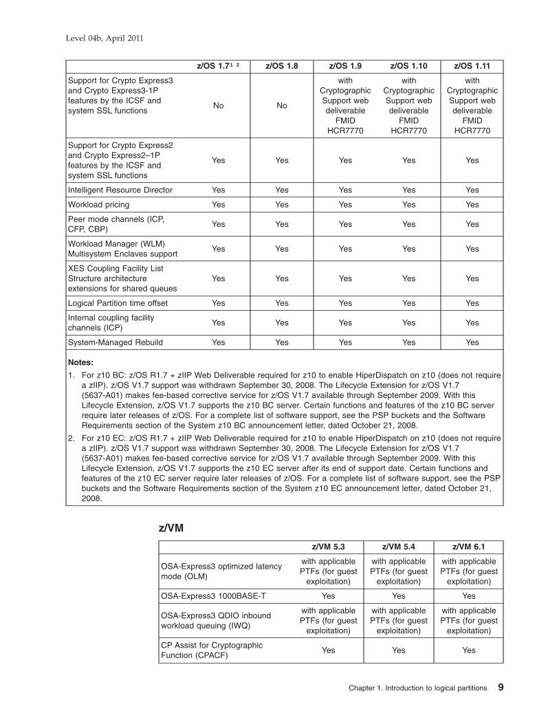
z/VM
z/VM 5.3 z/VM 5.4 z/VM 6.1
OSA-Express3 optimized latencymode (OLM)
with applicablePTFs (for guest
exploitation)
with applicablePTFs (for guest
exploitation)
with applicablePTFs (for guest
exploitation)
OSA-Express3 1000BASE-T Yes Yes Yes
OSA-Express3 QDIO inboundworkload queuing (IWQ)
with applicablePTFs (for guest
exploitation)
with applicablePTFs (for guest
exploitation)
with applicablePTFs (for guest
exploitation)
CP Assist for CryptographicFunction (CPACF)
Yes Yes Yes
Level 04b, April 2011
Chapter 1. Introduction to logical partitions 9

z/VM 5.3 z/VM 5.4 z/VM 6.1
Crypto Express3 (z10 EC and z10BC) and Crypto Express3-1P (z10BC only)
with applicablePTFs (for guest
exploitation).Supports
clear-key andsecure-keyoperations.
with applicablePTFs (for guest
exploitation).Supports
clear-key andsecure-keyoperations.
with applicablePTFs (for guest
exploitation).Supports
clear-key andsecure-keyoperations.
Support for System z10 ECwith applicable
PTFsYes Yes
Support for System z10 BCwith applicable
PTFsYes Yes
FICON Express8 (CHPID typeFC), using native FICON orChannel-To-Channel (CTC)
Yes Yes Yes
FICON Express8 (CHPID typeFCP) for support of SCSI disks
Yes Yes Yes
12x InfiniBand coupling links (12xIB-SDR or 12x IB-DDR)
with applicablePTFs. To define,
modify, anddelete anInfiniBand
coupling link,CHPID type CIB,when z/VM is thecontrolling LPARfor dynamic I/O
To define, modify,and delete an
InfiniBandcoupling link,
CHPID type CIB,when z/VM is thecontrolling LPARfor dynamic I/O
To define, modify,and delete an
InfiniBandcoupling link,
CHPID type CIB,when z/VM is thecontrolling LPARfor dynamic I/O
Long reach 1x InfiniBand couplinglinks (1x IB-SDR or 1x IB-DDR)
with applicablePTFs. To define,
modify, anddelete anInfiniBand
coupling link,CHPID type CIB,when z/VM is thecontrolling LPARfor dynamic I/O
To define, modify,and delete an
InfiniBandcoupling link,
CHPID type CIB,when z/VM is thecontrolling LPARfor dynamic I/O
To define, modify,and delete an
InfiniBandcoupling link,
CHPID type CIB,when z/VM is thecontrolling LPARfor dynamic I/O
Secure Key Advanced EncryptionStandard (AES)
for guestexploitation
for guestexploitation
for guestexploitation
Support for z/VM-mode partition No Yes Yes
Support for dynamic add ofReserved Central Storage
No Yes Yes
Support for z/VM SystemsManagement from the HMC
Yes Yes Yes
Support for installing Linux fromthe HMC
No Yes Yes
Dedicated OSA port to anoperating system
Yes Yes Yes
z/VM integrated systemsmanagement
Yes Yes Yes
zIIP and zAAP Simulation on CPs Yes Yes Yes
Support for zIIP Yes Yes Yes
Support for zAAP Yes Yes Yes
Level 04b, April 2011
10 PR/SM Planning Guide

z/VM 5.3 z/VM 5.4 z/VM 6.1
Maximum number of CPs 32 32 32
Maximum central storage 256 GB 256 GB 256 GB
Maximum expanded storage 128 GB 128 GB 128 GB
Maximum number of channelpaths
256 256 256
Maximum CFLEVEL supported with applicablePTFs (16 for
guestexploitation)
16 for guestexploitation
16 for guestexploitation
Able to use IFLs for OpenSolarisworkloads
Yes Yes Yes
Able to use IFLs for Linuxworkloads
Yes Yes Yes
System-managed Coupling Facilitystructure duplexing, for z/OSguests
Yes Yes Yes
CHPID type OSA performanceenhancements, for z/OS guests
Yes Yes Yes
CHPID type FCP performanceenhancements
Yes Yes Yes
Crypto Express2 and CryptoExpress2-1P feature (guest use)
Yes Yes Yes
FICON Express4-2C SX on thez9™ BC
Yes Yes Yes
Hardware Decimal Floating Pointfacilities
Yes Yes Yes
Support for z9 BC and z9 EC Yes Yes No
Support for FICON Express2(CHPID type FC), includingChannel-to-Channel (CTC)
Yes Yes Yes
Support for FICON Express2(CHPID type FCP), for nativesupport of SCSI disks and guestattachment
Yes Yes Yes
z/Architecture 64- bit addressing Yes Yes Yes
Peer mode channels (ICP, CFP,CBP)
Yes Yes Yes
Guest Coupling simulation Yes Yes Yes
Dynamic I/O configuration supportthrough the CP configurabilityfunction
Yes Yes Yes
Subspace group facility (guestuse)
Yes Yes Yes
Performance assist viapass-through of adapter I/Ooperations and interruptions forCHPID types FCP, IQD, and OSD
Yes Yes Yes
Level 04b, April 2011
Chapter 1. Introduction to logical partitions 11

z/VSE
z/VSE® 4.1 z/VSE 4.2
OSA-Express3 1000BASE-T Yes Yes
CP Assist for Crypotographic Function(CPACF)
with applicable PTFs with applicable PTFs
Crypto Express3 (z10 EC and z10 BC) andCrypto Express3-1P (z10 BC only)
No
with applicable PTFs(z/VSE supportsclear-key RSA
operations only.)
Support for System z10 EC Yes Yes
Support for System z10 BC Yes Yes
FICON Express8 (CHPID type FC), usingnative FICON or Channel-To-Channel (CTC)
Yes Yes
FICON Express8 (CHPID type FCP) forsupport of SCSI disks
Yes Yes
z/Architecture mode only and 64- bit realaddressing
Yes Yes
ESA/390 No No
31- bit addressing Yes Yes
Maximum central storage 8 GB 32 GB
OSA-Express3 family Yes Yes
OSA-Express2 family Yes Yes
Support for FICON Express2 (CPHID typeFC), including Channel-To-Channel (CTC)
Yes Yes
Support for FICON Express2 (CHPID typeFCP) for native support of SCSI disks
Yes Yes
Support for FICON Express4 (CPHID typeFC), including Channel-To-Channel (CTC)
Yes Yes
Support for FICON Express4 (CHPID typeFCP) for native support of SCSI disks
Yes Yes
CHPID type FCP performanceenhancements
Yes Yes
Configurable Crypto Express2 and CryptoExpress2-1P (z10 BC only) (z/VSE offerssupport for clear-key SSL transactions only)
Yes Yes
Features supported by z/VSE carriedforward from IBM System z9
Yes Yes
TPF (Transaction Processing Facility)
TPF 4.1 z/TPF 1.1
OSA-Express2 1000BASE-T Yes Yes
CP Assist for Cryptographic function(CPACF)
Yes Yes
Crypto Express3 (z10 EC and z10 BC) andCrypto Express3-1P (z10 BC only)
NoAcceleration mode
only
Support for System z10 EC Yes Yes
Level 04b, April 2011
12 PR/SM Planning Guide

TPF 4.1 z/TPF 1.1
Support for System z10 BC YesRequired to support
64 engines per z/TPFLPAR
FICON Express8 (CHPID type FC), usingnative FICON or Channel-To-Channel (CTC)
at PUT 16 Yes
Crypto Express2 (EC and BC) and CryptoExpress2-1P (BC only)
NoAcceleration mode
only
Support for FICON Express2 (CHPID typeFC), including Channel-to-Channel (CTC)
Yes Yes
ESA/390 or ESA/390 TPF mode Yes Yes
Maximum number of CPs (either shared ordedicated LP)
16 64
Maximum central storage 2048 MB 1 TB
Maximum CFLEVEL supported 9 (with APAR support) 9 (with APAR support)
Maximum number of channel paths 256 256
Linux on System z
Linux for S/390®
CP Assist for Cryptographic Function (CPACF) Yes
Crypto Express3 (z10 EC and z10 BC) and CryptoExpress3-1P (z10 BC only)
Current Novell SUSE andRed Hat distributions support
the same functionality asCrypto Express2. Secure key
is not supported.
Support for System z10 EC Yes
Support for System z10 BC Yes
FICON Express8 (CHPID type FC), using native FICON orChannel-To-Channel (CTC)
Yes
FICON Express8 (CHPID type FCP) for support of SCSIdisks
Yes
Crypto Express2 and Crypto Express2-1P configured as anaccelerator
Yes
Secure Key support on Crypto Express2 and CryptoExpress2-1P when using Linux Versions SUSE SP Level 10or Red Hat Rel 5
Yes
Support for FICON Express2 (CHPID type FC), includingChannel-To-Channel (CTC)
Yes
Support for FICON Express2 (CHPID type FCP) for supportof SCSI disks
Yes
OSA Express2 large send (also called TCP segmentationoffload)
Yes
Linux-Only mode Yes
Maximum number of CPs 16
Maximum central storage 2048 MB
Maximum expanded storage 262144 MB
Maximum number of channel paths 256
Level 04b, April 2011
Chapter 1. Introduction to logical partitions 13

Linux for S/390®
PKCS #11 API support Yes
WLM Management of shared logical processors Yes
Performance assist via passthrough of adapter interruptionsfor FCP, IQD, and OSD CHPID types
Yes
Support for SSL clear key RSA operations Yes
Hardware Configuration Definition (HCD)You can use the interactive panels of HCD to define configuration information bothto the CPC and to the operating system.
Note: HCD and Hardware Configuration Manager (HCM) are also available onz/VM.
HCD, running on z/OS allows you to dynamically change the current I/Oconfiguration of the CPC. HCD allows you to dynamically change the current I/Oconfiguration of the operating system and to create an IOCDS and make it theactive IOCDS.
HCD is required to define the I/O configuration to the operating system. HCD is alsothe recommended way to define hardware configurations.
The HCD component of z/OS allows you to define the hardware and software I/Oconfiguration information necessary for a parallel sysplex solution environment,including the capability to define:
v peer-mode channel paths (CFP, CBP, CIB, and ICP) to connect z/OS systems tocoupling facility images, and
v peer-mode channel paths (CFP, CBP, CIB, and ICP) to connect coupling facilityimages to one another, in support of System-Managed CF Structure Duplexing.
In addition to these two uses, the external coupling links (CFP, CBP, CIB) alsosupport STP timing signals
Additionally, HCD allows you to remotely write IOCDSs from one Support ElementCPC to another Support Element CPC as long as both Support Elements arepowered-on, LAN-attached, enabled for remote licensed internal code (LIC) update,and defined to the same Hardware Management Console.
Dynamic I/O configuration does not support:
v Adding or deleting LPs
v Changing MIF image ID numbers (the MIF image ID number is different from theLP identifier [ID])
When using HCD in z/OS, you can define and control the configuration of the CPCaffecting all LPs. Those LPs that run with HCD or z/VM can dynamically changetheir software configuration definitions. Other LPs might require an IPL in order touse the new configuration.
When you use HCD you must install, in the LP, the appropriate version of IOCP.Throughout the remainder of this publication, all the capabilities or restrictionsdocumented regarding the IOCP program, also apply to definitions entered andcontrolled through HCD.
Level 04b, April 2011
14 PR/SM Planning Guide

For more information about dynamic I/O configuration on z/OS, see:v z/OS Hardware Configuration Definition Planning, GA22-7525v z/OS Hardware Configuration Definition: User’s Guide, SC33-7988
z/VM dynamic I/O configurationYou can dynamically change the current I/O configuration of the CPC. You can alsochange the current I/O configuration of the operating system and create an IOCDSand make it the active IOCDS.
Dynamic I/O configuration does not support:v Adding or deleting LPsv Changing MIF image ID numbers (the MIF image ID number is different from the
LP identifier [ID])
You can define and control the configuration of the CPC affecting all LPs. ThoseLPs that run z/VM can dynamically change their software configuration definitions.
Input/Output Configuration Program (IOCP) supportTo perform a power-on reset you must use an LPAR IOCDS. To generate an LPARIOCDS you need to use the ICPIOCP program.
PTFs for supported IOCP versions must be applied and can be obtained from theIBM Software Support Center. For more information about ICPIOCP, see System zInput/Output Configuration Program User’s Guide for ICP IOCP, SB10-7037.
Hardware supportLPs operate independently but can share access to I/O devices and CPCresources. Each active LP must have sufficient channel paths and storage to meetthe particular requirements of that LP. Additional central storage, expanded storage,channel paths, consoles, and other I/O devices might be necessary for the plannedconfiguration of LPs.
Operator trainingA general knowledge of z/Architecture and ESA/390 is useful and, in some cases,required of all technical support personnel, LPAR planners, and operators.
Generally, the operator performs the following tasks:
v Edit activation profiles
– Reset profiles- Select an IOCDS- Optionally specify LP activation sequence
– Image profiles- Define LP characteristics- Optional automatic load specification
– Load profiles
v Performing a CPC activation
v Activating an LP
v Performing a load on an LP or activating a load profile
v Deactivating a CPC
v Deactivating an LP
Level 04b, April 2011
Chapter 1. Introduction to logical partitions 15

Logical partitionsThis section provides an overview of LP characteristics. Some of the characteristicsdescribed in this section are model-dependent, EC-level dependent,MCL-dependent, LP mode dependent, or control-program dependent. For thisreason, all the characteristics described here are not necessarily available on allCPCs.
The resources of a CPC can be distributed among multiple control programs thatcan run on the same CPC simultaneously. Each control program has the use ofresources defined to the logical partition in which it runs.
You can define an LP to include:v One or more CPsv Central storagev Channel pathsv Optional expanded storagev Two or more optional cryptos (Crypto Express2 and/or Crypto Express3). A single
crypto engine can be defined, for test purposes, but it is not recommended forproduction LPs.
An LP can be defined to include CPs, zAAPs, and zIIPs, ICFs, and/or IFLs. Theallowed combinations of defined processor types for an LP depends on the definedmode of the logical partition. Refer to Table 18 on page 158.
You can also define an LP to be a coupling facility running the coupling facilitycontrol code.
CharacteristicsLPs can have the following characteristics. For more information or details aboutexceptions to any of these characteristics, see “Determining the characteristics” onpage 103.
v The maximum number of LPs you can define on a z10 EC is 60 (and 30 LPs ona z10 BC).
v LPs can operate in ESA/390, ESA/390 TPF, Linux-Only, z/VM, or coupling facilitymode.
v The storage for each LP is isolated. Central storage and expanded storagecannot be shared by LPs.
v Using dynamic storage reconfiguration, an LP can release storage or attachstorage to its configuration that is released by another LP.
v All channel paths can be defined as reconfigurable. Channel paths are assignedto LPs. You can move reconfigurable channel paths between LPs using tasksavailable from either the Hardware Management Console or the Support Elementconsole. If the control program running in the LP supports physical channel pathreconfiguration, channel paths can be moved among LPs by control programcommands without disruption to the activity of the control program.
v MIF allows channel paths to be shared by two or more LPs at the same time. AllCHPID types except CVC and CBY can be shared.
v With a non-E64 model, the maximum number of CPs that can be defined is 56.However the total number of logical processors that can be defined is 64. Forexample, one could specify 8 initial CPs, 48 reserved CPs, and 8 reservedzAAPs. For a Model E64, the maximum number of CPs that can be defined is64.
Level 04b, April 2011
16 PR/SM Planning Guide

CPs can be dedicated to LPs or shared by them. CPs that you define asdedicated to an LP are not available to perform work for other active LPs. Theresources of shared CPs are allocated to active LPs as needed. You can cap(limit) CP resources, if required. A CP LP has a maximum of 16 processors (ICFsor CPs), regardless of the model.
You cannot define a mix of shared and dedicated CPs for a single LP. CPs for anLP are either all dedicated or all shared. However, you can define a mix of LPswith shared CPs and LPs with dedicated CPs and activate them concurrently.
For security purposes, you can:
– Reserve reconfigurable channel paths for the exclusive use of an LP (unlessoverridden by the operator)
– Limit the authority of an LP to read or write any IOCDS in the configurationand limit the authority of an LP to change the I/O configuration dynamically
– Limit the authority of an LP to retrieve global performance data for all LPs inthe configuration
– Limit the authority of an LP to issue certain control program instructions thataffect other LPs
Figure 1 shows some of the characteristics that can be defined for an LP. Youcan view each LP as a CPC operating within the physical CPC.
Level 04b, April 2011
Chapter 1. Introduction to logical partitions 17

ZVSE ZVM
Figure 1. Characteristics of logical partitions
Level 04b, April 2011
18 PR/SM Planning Guide

Potential applicationsThe use of LPs allows multiple systems, including the I/O for the systems, to bemigrated to a single CPC while maintaining the I/O performance, recovery, andmultipathing capability of each system, and with minimum impact to the systemgeneration procedures.
LPs are suitable for consideration in the following environments:
ConsolidationMultiple production system images can be consolidated onto 1 CPCwithout having to merge them into one image.
Migration Control programs or applications can be migrated by running theold and new systems or applications in independent LPs that areactive on the same CPC at the same time.
Production and testMultiple production and test systems can run on the same CPC atthe same time.
Coupling facilityA coupling facility enables high performance, high integrity datasharing for those CPCs attached to it and configured in a sysplex.
Coupled systemsMultiple instances of the same workload can be run in multiple LPson one or more CPCs as part of a sysplex configuration that takesadvantage of the centrally accessible, high performance datasharing function provided by the coupling facility.
Extended Recovery Facility (XRF)Primary and alternate XRF systems can run on 1 CPC. Multiple andalternate XRF systems can run on 1 CPC.
Communications Management Configuration (CMC)The communications management configuration (CMC) machine,typically run on a separate CPC, can be run as an LP on the sameCPC.
Departmental systemsMultiple applications can be isolated from one another by runningeach in a separate LP.
Constrained systemsThose systems that cannot fully use a large system because ofstorage constraints can alleviate the problem by using LPs to definemultiple system images on the same CPC.
Diverse workloadsInteractive workloads such as the Customer Information ControlSystem (CICS®) and time-sharing option (TSO) can be isolated byrunning each in a separate LP.
Level 04b, April 2011
Chapter 1. Introduction to logical partitions 19

Examples of logical partition applicationsFigure 2 and Figure 3 show examples of how LPs on a CPC can be used tosupport multiple systems.
Figure 2 represents the migration of two z/OS, one z/VM, and one stand-alonecoupling facility systems onto a single CPC. These systems, which were running onfour separate IBM z900 CPCs, now operate as four LPs on a single z10 EC. TwoLPs are each running a z/OS system in ESA/390 mode, one is running a z/VMsystem in ESA/390 mode, and one is running in coupling facility mode.
Figure 3 represents a CPC with three LPs: an active XRF system, an alternate XRFsystem, and an alternate for another primary XRF system.
z900 z900 z900 z900
Figure 2. Migration of four production systems to LPs
LP2
XRFAlt1
LP3
XRFAlt2
LP1
XRFPrimary
System z10
Figure 3. Support for three XRF systems
Level 04b, April 2011
20 PR/SM Planning Guide

Compatibility and migration considerationsThis section provides migration and compatibility information for the System z10.
Device numbersWhen multiple systems are migrated to a System z10 CPC, the combination ofsystems could include different devices or shared devices with identical devicenumbers. Each system can operate in an LP without changing the device numbersas long as identical device numbers do not occur in the same LP. However,duplicate device numbers can exist in the same LP if these device numbers are indifferent subchannel sets.
Duplicate device number conflicts can occur when the I/O configuration isreconfigured. For example, if a reconfigurable channel path is reassigned to anotherLP and devices attached to the channel path have device numbers that are alreadyassigned in the receiving LP to other online channel paths, a conflict results. WhenIOCP generates an LPAR IOCDS, the initial configuration contains no duplicatedevice number conflicts in an LP.
Device number conflicts are also detected when operator tasks change the I/Oconfiguration (channel path tasks from the Hardware Management Console orSupport Element console; or control program configuration command) or during LPactivation.
Duplicate device number conflicts are also detected when a dynamic I/Oconfiguration change is made.
Multiple Subchannel Sets (MSS)Multiple Subchannel Sets (MSS) allow increased device connectivity for ParallelAccess Volumes (PAVs). Two subchannel sets per Logical Channel Subsystem(LCSS) are designed to enable a total of 63.75K subchannels in set-0 and theaddition of 64K - 1 subchannels in set-1. MSS is supported by ESCON (CHPIDtype CNC), FICON when configured as CHPID type FC, and z/OS.
Control programsPTFs for supported control programs must be applied and can be obtained from theIBM Software Support Center. A supported control program operates in an LP as itdoes in one of the basic modes, with the following exceptions:
z/OSv Physical reconfiguration, either offline or online, of CPs is not supported on the
System z10. Logical CP reconfiguration, either offline or online, is supported inan LP. It does not affect the online/offline status of the physical CPs. Toreconfigure a logical CP offline or online, use the following z/OS operatorcommand:CF CPU(x),<OFFLINE/ONLINE>
v Physical reconfiguration, either offline or online, of central and expanded storageis supported.
To reconfigure a central storage element offline or online, use the following z/OSoperator command:CF STOR(E=1),<OFFLINE/ONLINE>
Additionally you can use the following command to reconfigure smaller amountsof central storage online or offline:
Level 04b, April 2011
Chapter 1. Introduction to logical partitions 21

CF STOR(nnM),<OFFLINE/ONLINE>
Reconfigurable Storage Unit (RSU) Considerations: Set the RSU parameterto the same value that you specified in the central storage Reserved field. Seez/OS MVS™ Initialization and Tuning Reference for appropriate RSU parametersyntax.
v Reconfiguration, either offline or online, of channel paths by z/OS operatorcommands is supported on a System z10. This capability also allows channelpaths to be moved among LPs using z/OS operator commands.
v Preferred paths to a device are supported on a System z10. If the preferred pathparameter is specified in an LPAR IOCDS, it is accepted.
v Specifying SHAREDUP for devices is not recommended. If used, z/OS treats thedevice as a SHARED device.
v Each z/OS LP can run the Resource Measurement Facility™ (RMF). RMFenhancements for PR/SM allow a single LP to record system activities and reportthem in the Partition Data Report. To enable this function, use the Change LPARSecurity task available from the CPC Operational Customization task list andselect Performance Data Control for the LP.
For z/OS, RMF reporting includes LPAR Management Time.
v RMF provides enhanced reporting for coupling facility configurations.
v RMF with APAR support identifies which logical and physical CPs are of eachtype when any combination of general purpose, zAAP, IFL, zIIP and ICFprocessors are present in the configuration on its partition data report. You canhave up to 32 virtual machines running z/OS within a simulated sysplex, witheach z/OS virtual machine coupled to up to eight virtual machines running ascoupling facilities.
EREPEach control program operating in an LP has its own environmental recording,editing, and printing (EREP) processing. EREP records for ICP channel paths go tothe z/OS logs of the z/OS systems attached to a coupling facility LP.
Level 04b, April 2011
22 PR/SM Planning Guide

CPU IDs and CPU addressesCheck application packages and software products that are licensed to run underspecific CPU identification (CPU ID) information, because they might need to beupdated.
CPU ID information is system-generated for each logical CP in the LP during the LPactivation. It consists of a version code for the CPC machine type, a CPUidentification number that is unique for each logical partition, a model number forthe CPC machine type, and a value of X'8000'.
The Store CPU ID (STIDP) instruction stores the CPU ID for each logical CP instorage in the following format (Figure 4):
Figure 5 shows the format of the CPU identification number (bits 8 through 31 ofthe CPU ID format).
CPU ID fieldsThe CPU identification number, with the version code and the machine type,permits a unique CPU ID for each logical partition.
v The version code for the System z10 is always zero and is not affected by theoperating mode.
v The CPU identification number for each logical CP (see Figure 5) consists of atwo-digit LP identifier, and digits derived from the serial number of the CPC.
– The logical partition identifier is specified using the Partition identifier fieldon the General page in either the reset or image profile used by the LP andmust be unique for each active LP in the configuration.
v The following machine types (CPC model numbers) are returned as indicated:
Machine type Models
2097 System z10 EC(E12, E26, E40, E56, E64)
2098 System z10 BC(E10)
0
VersionCode
Machine Type 8000CPU Identification
Number
637 8 31 32 47 48
Figure 4. CPU ID format
Pn
Logical partition identifierDigit derived from the serial number
PPnnnn
Legend :
Figure 5. CPU identification number format
Level 04b, April 2011
Chapter 1. Introduction to logical partitions 23

Note: STIDP is provided for purposes of compatibility with earlier version. IBMhighly recommends that you use the Store System Information instruction(STSI), rather than STIDP. STSI is the preferred means to obtain all CPUinformation including machine serial number. When a unique logical CPUaddress is all that is required, use the Store CPU Address (STAP)instruction.
Examples of CPU ID informationThe following examples show the format and contents of the CPU ID informationstored by the STIDP instruction for logical CPs in active LPs.
Table 3 shows the CPU ID information for a z10 EC with 3 active LPs.
Table 3. CPU IDs for a z10 EC
LP nameLP
identifierNumber of
CPs defined CPU ID returned by STIDP
ZVSE 1 1 00 019999 2097 8000
ZOSTEST 2 1 00 029999 2097 8000
ZOSPROD 3 8 00 039999 2097 800000 039999 2097 800000 039999 2097 800000 039999 2097 800000 039999 2097 800000 039999 2097 800000 039999 2097 800000 039999 2097 8000
Level 04b, April 2011
24 PR/SM Planning Guide

HSA allocationz10 EC has a fixed Hardware System Area (HSA) size of 16 GB. The z10 BC has afixed HSA size of 8 GB.
TOD clock processingThe CPC TOD clocks of all the CPs are automatically set during CPC activation.The time reference used depends on whether a Sysplex Timer® is attached to theCPC or Server Time Protocol (STP) is enabled. When STP is enabled, a CPC canparticipate in: an ETR network, a Mixed Coordinated Timing Network (CTN), or anSTP-only CTN. In an ETR network or Mixed CTN, the Sysplex Timer provides thetimekeeping information. In an STP-only CTN, the Sysplex Timer is no longerrequired. In this case the Current Time Server for the STP-only CTN provides thetime information.
No sysplex timer attached and Server Time Protocol not enabledDuring PR/SM initialization, the CPC TOD clocks for each CP are set to the TODvalue of the Support Element. Each LP starts out with this CPC TOD value at thecompletion of LP activation. The operating system running in an LP can set a TODvalue for itself and this is the only TOD reference it sees. Setting the TOD clock forone logical CP in the LP sets the TOD clock for all logical CPs in that LP, but doesnot affect the logical CPs in any other LP. The TOD clock value is used for theduration of the LP activation, or until a subsequent Set Clock instruction is issued inthe LP.
Sysplex timer attachedThe attachment and use of an IBM Sysplex Timer is supported. Also, during PR/SMinitialization, when a Sysplex Timer is attached, the CPC TOD clocks for each CPare set to the TOD value from the Sysplex Timer.
The operating system in each LP can independently choose whether to synchronizeto the Sysplex timer if one is present. Operating systems in LPs that do synchronizeto the Sysplex Timer all run with identical TOD values. Operating systems in LPsthat do not synchronize to the Sysplex Timer do not need to be aware of thepresence of a Sysplex Timer and can set their TOD values independently of allother LPs.
z/OS does not allow you to change the value of the TOD setting when it is usingthe Sysplex Timer (ETRMODE=YES in the CLOCKxx parmlib member).
The System z10 models support the specification of a logical partition time offset.When all members of a sysplex are in logical partitions on these supported models,the Logical partition time offset can be used for:
v Different local time zone support in multiple sysplexes using the same sysplextimer. Many sysplexes have the requirement to run with a LOCAL=GMT setting ina sysplex (ETRMODE=YES) where the time returned from a Store Clockinstruction yields local time. To fulfill this requirement, the time returned by thesysplex timer must be local time. Before Logical partition time offset support, thisrequirement could only be accomplished for one sysplex for a given sysplextimer. With Logical partition time offset support, multiple sysplexes can each havetheir own local time reported to them from the sysplex timer if wanted. Forinstance, the sysplex timer can be set to GMT, one set of sysplex partitions couldspecify a Logical partition time offset of minus 5 hours, and a second set ofsysplex partitions could specify a Logical partition time offset of minus 6 hours.
Level 04b, April 2011
Chapter 1. Introduction to logical partitions 25

Server Time Protocol enabledThe enablement of STP is supported. Also, during PR/SM initialization, when STP isenabled, the CPC TOD clocks for each CP are set to the TOD value from STP.
The operating system in each LP can independently choose whether to synchronizeto the current time source for STP, if present. Operating systems in LPs that dosynchronize to STP run with identical TOD values. Operating systems in LPs thatdo not synchronize to STP do not need to be aware of the presence of STP andcan set their TOD values independently of all other LPs.
z/OS does not allow you to change the value of the TOD setting when synchronizedto STP (STPMODE=YES in the CLOCKxx parmlib member).
The System z10 models support the specification of a logical partition time offset.When all members of a sysplex are in logical partitions on these supported models,the Logical partition time offset can be used for:
v Different local time zone support in multiple sysplexes using the same CTN.Many sysplexes have the requirement to run with a LOCAL=GMT setting in asysplex (STPMODE=YES) where the time returned from a Store Clock instructionyields local time. To meet this requirement, the time returned by STP must belocal time. With Logical partition time offset support, multiple sysplexes can eachhave their own local time reported to them from STP if wanted. For instance,STP can be set to GMT, one set of sysplex partitions could specify a Logicalpartition time offset of minus 5 hours, and a second set of sysplex partitionscould specify a Logical partition time offset of minus 6 hours.
External coupling links (such as CFP, CBP, CIB) are also valid to pass timesynchronization signals for Server Time Protocol (STP). Therefore the samecoupling links can be used to exchange timekeeping information and CouplingFacility messages in a Parallel Sysplex.
Sysplex testing without a Sysplex Timer and Server Time Protocol notenabled
You can do sysplex testing without a Sysplex Timer or Server Time Protocolenabled by setting up a test sysplex of several z/OS LPs in multiple LPs in thesame PR/SM LPAR configuration. Use the SIMETRID keyword in the CLOCKxxparmlib member for z/OS to synchronize the members of the sysplex in the LPs.
Synchronized Time Source and the coupling facilityImproved processor and coupling facility link technologies inherent on System z10models necessitate more rigorous time synchronization tolerance for members of aparallel sysplex hosted by those models. To help ensure that any exchanges oftime-stamped information between members of a sysplex observe the correct timeordering, time stamps are now included in the message-transfer protocol betweenthe systems and the coupling facility.
Consequently, a coupling facility hosted by any System z10 model requiresconnectivity to the same synchronized time source as the other z/OS systems in itsparallel sysplex. If a member of its parallel sysplex is on the same server as thecoupling facility, required connectivity is already provided to the synchronized timesource. However, when a coupling facility is a resident of a System z10 model,which does not include a member of the coupling facilities parallel sysplex,connectivity attached to the synchronized time source must be implemented.
Level 04b, April 2011
26 PR/SM Planning Guide

Extended TOD-clock facilityThe extended TOD-clock facility provides an extended form TOD clock and a TODprogrammable register. The extended form TOD clock is a 128- bit value thatextends the current basic form by appending 8 bits on the left and 56 bits on theright. The extended form TOD clock is returned by a new problem-programinstruction, STORE CLOCK EXTENDED (STCKE). The contents of the TODprogrammable register are stored into the rightmost portion of the extended formTOD value when the TOD clock is inspected by STCKE. A TOD programmableregister exists for each CPU and contains the TOD programmable field in bits16-31. The TOD programmable register is set by a new privileged instruction, SETTOD PROGRAMMABLE FIELD (SCKPF). The leftmost byte of the extended formTOD clock is the TOD Epoch Index (TEX), and is stored as zeros in machinesrunning ESA/390.
The extended TOD clock facility satisfies three main objectives:
v Relieve constraints that exist in the current 64- bit TOD clock
v Extend the TOD-clock architecture to multi-system configurations
v Help ensure sysplex-wide uniqueness of the STCKE TOD values
The TOD Programmable Field (TODPF) is a 16- bit quantity contained in bitpositions 16-31 of the TOD programmable register. The contents of the register canbe set by the privileged instruction SET TOD PROGRAMMABLE FIELD. Thecontents of the register can be stored by the instruction STORE CLOCKEXTENDED, which stores the TOD programmable field in the last 16 bits of theextended form TOD clock. The contents of the register are reset to a value of allzeros by an initial CPU reset.
Clock Comparator on Shared ProcessorsThe clock comparator has the same format as bits 0-63 of the TOD clock. The clockcomparator nominally consists of bits 0-47, which are compared with thecorresponding bits of the TOD clock. On some models, higher resolution is obtainedby providing more than 48 bits. In most cases, a logical processor running in alogical partition receives the model's resolution for the clock comparator.
However, when using shared logical processors in a logical partition, if the operatingsystem running in a logical partition loads an enabled wait state with a clockcomparator set on that logical processor, the LPAR Hipervisor tracks that clockcomparator value for the logical partition's processor at a less granular resolution.The granularity can be reduced to as little as bits 0-45 of the intended clockcomparator value. This effect is not seen on dedicated logical processors nor is itseen on logical processors that are not in wait state.
Level 04b, April 2011
Chapter 1. Introduction to logical partitions 27

Level 04b, April 2011
28 PR/SM Planning Guide

Chapter 2. Planning considerations
Overview . . . . . . . . . . . . . . . . . . . . . . . . . . . 31Planning the I/O configuration . . . . . . . . . . . . . . . . . . . 31
Planning considerations . . . . . . . . . . . . . . . . . . . . 31Control program support . . . . . . . . . . . . . . . . . . . 31Hardware Configuration Definition (HCD) support . . . . . . . . . . 31z/VM Dynamic I/O configuration support . . . . . . . . . . . . . 32Input/Output Configuration Program (IOCP) support . . . . . . . . . 32Characteristics of an IOCDS . . . . . . . . . . . . . . . . . . 32
Maximum number of logical partitions . . . . . . . . . . . . . . . 33Determining the size of the I/O configuration . . . . . . . . . . . . 33Maximum size of the I/O configuration . . . . . . . . . . . . . . 33Guidelines for setting up the I/O configuration . . . . . . . . . . . 33Recovery considerations . . . . . . . . . . . . . . . . . . . 34
Managing logical paths for ESCON and FICON channels . . . . . . . . 35Definition . . . . . . . . . . . . . . . . . . . . . . . . . 35Control unit allocation of logical paths . . . . . . . . . . . . . . 35Why manage logical paths? . . . . . . . . . . . . . . . . . . 35
Managing the establishment of logical paths . . . . . . . . . . . . . 39Logical path considerations . . . . . . . . . . . . . . . . . . 39Recommendations . . . . . . . . . . . . . . . . . . . . . 40
Shared channel overview . . . . . . . . . . . . . . . . . . . . 49MIF requirements . . . . . . . . . . . . . . . . . . . . . . 49Understanding ESCON and MIF topologies . . . . . . . . . . . . 49MIF performance planning considerations . . . . . . . . . . . . . 50
Unshared ESCON or FICON channel recommendations. . . . . . . . . 55Dynamically managed CHPIDs . . . . . . . . . . . . . . . . . . 55IOCP coding specifications . . . . . . . . . . . . . . . . . . . 56
IOCP statements for ICP . . . . . . . . . . . . . . . . . . . 56Shared devices using shared channels . . . . . . . . . . . . . . 59Shared devices using unshared channels . . . . . . . . . . . . . 59Duplicate device numbers for different physical devices . . . . . . . . 61
Coupling facility planning considerations . . . . . . . . . . . . . . . 67Test or migration coupling configuration . . . . . . . . . . . . . . . 67
CFCC Enhanced Patch Apply . . . . . . . . . . . . . . . . . 67Production coupling facility configuration . . . . . . . . . . . . . . 68
Production coupling facility configuration for full data sharing . . . . . . 68Production coupling facility configuration for resource sharing . . . . . . 68
Internal Coupling Facility (ICF) . . . . . . . . . . . . . . . . . . 69Dynamic Coupling Facility Dispatching (DCFD) . . . . . . . . . . . 70
System-managed coupling facility structure duplexing. . . . . . . . . . 71Coupling Facility Level 16 duplexing enhancements . . . . . . . . . 71
Single CPC software availability sysplex . . . . . . . . . . . . . . 72Coupling facility nonvolatility . . . . . . . . . . . . . . . . . . . 72
Nonvolatility choices . . . . . . . . . . . . . . . . . . . . . 72Setting the conditions for monitoring coupling facility nonvolatility status 72
Coupling facility mode setting . . . . . . . . . . . . . . . . . . 73Coupling facility LP definition considerations . . . . . . . . . . . . . 73
Internal Coupling Facility (ICF) . . . . . . . . . . . . . . . . . 73Coupling facility LP storage planning considerations . . . . . . . . . . 74
Structures, dump space, and coupling facility LP storage . . . . . . . 74Estimating coupling facility structure sizes . . . . . . . . . . . . . 74
Dump space allocation in a coupling facility . . . . . . . . . . . . . 75Coupling facility LP activation considerations . . . . . . . . . . . . . 75
Level 04b, April 2011
© Copyright IBM Corp. 2008, 2010 29

Coupling facility shutdown considerations . . . . . . . . . . . . . . 76Coupling facility LP operation considerations . . . . . . . . . . . . . 76Coupling facility control code commands . . . . . . . . . . . . . . 76Coupling facility level (CFLEVEL) considerations . . . . . . . . . . . 77
CPC support for coupling facility code levels . . . . . . . . . . . . 77Level 16 coupling facility . . . . . . . . . . . . . . . . . . . 78Level 15 coupling facility . . . . . . . . . . . . . . . . . . . 79Level 14 coupling facility . . . . . . . . . . . . . . . . . . . 79Level 13 coupling facility . . . . . . . . . . . . . . . . . . . 80Level 12 coupling facility . . . . . . . . . . . . . . . . . . . 80
Coupling Facility Resource Management (CFRM) policy considerations . . . 80Coupling facility channels . . . . . . . . . . . . . . . . . . . . 81
Internal Coupling channel . . . . . . . . . . . . . . . . . . . 82Integrated cluster bus channels . . . . . . . . . . . . . . . . . 82ISC-3 Links . . . . . . . . . . . . . . . . . . . . . . . . 83InfiniBand host channel adapter (HCA) . . . . . . . . . . . . . . 83InifiniBand coupling links for Parallel Sysplex . . . . . . . . . . . . 83Coupling facility channels (TYPE=CFP, TYPE=CBP, TYPE=CIB, or
TYPE=ICP) . . . . . . . . . . . . . . . . . . . . . . . 84Defining internal coupling channels (TYPE=ICP) . . . . . . . . . . 85I/O configuration considerations. . . . . . . . . . . . . . . . . 85
Considerations when migrating from ICMF to ICs . . . . . . . . . . . . 86Linux operating system planning considerations . . . . . . . . . . . . . 86
Integrated Facility for Linux (IFL) . . . . . . . . . . . . . . . . . 86z/VM utilizing IFL features . . . . . . . . . . . . . . . . . . . . 87
IBM System z10 Application Assist Processor (zAAP). . . . . . . . . . . 87IBM System z10 Integrated Information Processor (zIIP) . . . . . . . . . 88Concurrent patch . . . . . . . . . . . . . . . . . . . . . . . . 89CFCC enhanced patch apply. . . . . . . . . . . . . . . . . . . . 89Dynamic capacity upgrade on demand . . . . . . . . . . . . . . . . 90
PR/SM shared partitions . . . . . . . . . . . . . . . . . . . . 90Mixed shared and dedicated PR/SM partitions . . . . . . . . . . . . 91Multiple dedicated PR/SM partitions . . . . . . . . . . . . . . . . 92Shared Internal Coupling Facility . . . . . . . . . . . . . . . . . 92
Dynamic capacity upgrade on demand limitations . . . . . . . . . . . . 93Concurrent Memory Upgrade. . . . . . . . . . . . . . . . . . . . 94Capacity Backup Upgrade (CBU) capability . . . . . . . . . . . . . . 94Enhanced Book Availability . . . . . . . . . . . . . . . . . . . . 95
Preparing for Enhanced Book Availability . . . . . . . . . . . . . . 95Getting the system ready to perform Enhanced Book Availability. . . . . 95Reassigning non-dedicated processors . . . . . . . . . . . . . . 97
Customer Initiated Upgrade (CIU) . . . . . . . . . . . . . . . . . . 97Concurrent Processor Unit conversion . . . . . . . . . . . . . . . . 98Planning for nondisruptive install of crypto features . . . . . . . . . . . 98
Level 04b, April 2011
30 PR/SM Planning Guide

OverviewThis chapter describes planning considerations for I/O configuration and forcoupling facility LPs.
Planning the I/O configurationThis section describes the planning considerations and guidelines for creating anIOCDS. It assumes that you understand the IOCP configuration and codingrequirements described in the System z Input/Output Configuration Program User’sGuide for ICP IOCP, SB10-7037.
Planning considerationsPR/SM is standard on all System z10 models.
Control program supportThe maximum number of supported devices is limited by the control program. Inplanning an I/O configuration, determine the maximum number of devices supportedby the control program run in each LP. See the documentation for the respectiveoperating systems.
Hardware Configuration Definition (HCD) supportHCD supports definition of the I/O configuration for an entire installation. It isrequired for parallel sysplex and LPAR clusters. A single I/O data file is created forthe installation and used for multiple machines and I/O configuration data sets.
HCD supports:
v Up to 60 logical partitions (LPs) per central processing complex (CPC) on a z10EC, or 30 logical partitions on a z10 BC.
v Coupling facility configurations
v Multiple Image Facility (MIF)
v Dynamic CHPID Management (DCM) channel paths.
v MCSS
v Assigning reserved logical partitions a meaningful name
Table 4. HCD function support
HCD Function z/OS z/VM
Define 60 logical partitions? Yes Yes
Define shared channel paths? Yes Yes
Define coupling facility channel paths? Yes Yes ²
Define dynamically managed channel paths? Yes Yes ²
Write IOCDSs remotely? Yes ¹ No
Access I/O devices on shared channel paths? Yes Yes
Use software-only dynamic I/O? Yes Yes
Level 04b, April 2011
Chapter 2. Planning considerations 31

Table 4. HCD function support (continued)
HCD Function z/OS z/VM
Notes:
1. HCD, running on z/OS, allows you to remotely write IOCDSs from one CPC to anotherCPC that is powered on, LAN-attached, enabled for remote LIC update, and defined tothe same Hardware Management Console.
2. HCD, running on z/VM, allows you to define coupling facility channel paths or managedchannel paths for a z/OS LP but z/VM does not support coupling facility channel pathsor dynamically managed channel paths for use by z/VM or guest operating systems.
For more information about using HCD with Multiple Image Facility, seev z/OS Hardware Configuration Definition: User’s Guide, SC33-7988v z/OS Hardware Configuration Definition Planning, GA22-7525v z/VM I/O Configuration, SC24-6100.
z/VM Dynamic I/O configuration support
z/VM support for the coupling facility: z/VM allows you to define configurationsthat use the coupling facility. However, z/VM does not support the coupling facilityitself. (z/VM does virtualize the coupling facility for guest test purposes). Instead,the dynamic I/O configuration capability available on z/VM allows you to defineresources that can be used by a z/OS system in another LP. For a summary of thesupport of dynamic I/O configuration on z/VM, see Table 5.
z/VM support for the Multiple Image Facility (MIF): You can use z/VM to defineshared channel paths. For a summary of z/VM support of dynamic I/O configuration,see Table 5.
Table 5. z/VM dynamic I/O support for MIF and the coupling facility
z/VM Function
Release
5.3, 5.4, and 6.1
Define shared channel paths? Yes
Define coupling facility channel paths? Yes (Note)
Write IOCDSs remotely? No
Access I/O devices on shared channel paths? Yes
Use software-only dynamic I/O? Yes
Use hardware and software dynamic I/O? Yes
Use shared ESCON CTCs? Yes
Note: z/VM can define coupling facility channel paths for a z/OS LP but does not supportreal coupling facility channel paths for use by z/VM or guest operating systems.
Input/Output Configuration Program (IOCP) supportYou can create up to four IOCDSs. ICP IOCP is the required supported version.You can define as many as 60 LPs. For more information about ICP IOCP, seeSystem z Input/Output Configuration Program User’s Guide for ICP IOCP,SB10-7037.
Characteristics of an IOCDSThe definitions for channel paths, control units, and I/O devices are processed bythe IOCP and stored in an IOCDS. During initialization of the CPC, the definitions of
Level 04b, April 2011
32 PR/SM Planning Guide

a selected IOCDS are transferred to the hardware system area (HSA). The IOCDSis used to define the I/O configuration data required by the CPC to control I/Orequests.
Channel paths in an IOCDS are assigned to one or more LPs. The characteristicsof an IOCDS are:
v Using the IOCP RESOURCE statement, you define logical channel subsystems(CSSs) and the logical partitions that have access to the channel paths in a CSS.
v Using the IOCP RESOURCE statement, you can name logical partitions andassign MIF image ID numbers to them. MIF image ID numbers are necessary forESCON CTC and FICON CTC definitions.
v Using the IOCP CHPID statement, you can assign a channel path asreconfigurable or shared.
v Using the IOCP CHPID statement, you can specify a Dynamic CHPIDManagement (DCM) channel path and the cluster to which the CHPID belongs.The CHPID is shareable among active LPs that have become members of thespecified cluster.
v You can duplicate device numbers within a single IOCP input file, but the devicenumbers cannot be duplicated within an LP. See “IOCP coding specifications” onpage 56.
Maximum number of logical partitionsThe maximum number of LPs supported by z10 EC is 60. The z10 BC supports amaximum of 30 LPs.
Determining the size of the I/O configurationTo determine the size of the current I/O configuration (number of control unitheaders and devices), review the IOCDS Totals Report for the current IOCDS.
Maximum size of the I/O configurationLimits within an I/O configuration exist for the following:v Devicesv Control unit headersv Physical control units
System z10 models:v The maximum number of control unit headers (CUHs) is 4096 per logical channel
subsystem (CSS).v The maximum number of physical control units is 8192.v The maximum number of devices is 65280 per CSS for subchannel set 0.v The maximum number of devices is 65535 per CSS for subchannel set 1.
Guidelines for setting up the I/O configurationFollow these guidelines when setting up an I/O configuration.
1. Determine the number of LPs and in which logical channel subsystem (CSS)they exist.
2. For dynamic I/O configurations, include any logical partitions for which you donot yet have a meaningful name. These logical partitions are reserved until asubsequent dynamic I/O configuration change is made to assign them a name.
3. Determine if you want to move any channel paths among LPs. If you do, thenthese channel paths must be defined as reconfigurable in the IOCP CHPIDstatement. You cannot move a channel path from an LP in one CSS to an LP inanother CSS.
Level 04b, April 2011
Chapter 2. Planning considerations 33

4. Determine if you want to share any channel paths among LPs in the same CSS.If you do, then specify these channel paths as SHARED in the IOCP CHPIDstatement. This specification helps reduce the number of channel pathsconfigured to a physical control unit and device. Make sure that the channelpath type supports being shared.
5. Determine if you want to share any channel paths among LPs in different CSSs.If you do, then define these channel paths as spanned by specifying multipleCSS IDs in the PATH keyword of the IOCP CHPID statement. This specificationfurther helps reduce the number of channel paths configured to a physicalcontrol unit and device. Make sure that the channel path type supports beingspanned.
6. Within each LP, configure primary and backup paths from separate channeladapter cards.
7. Within each LP, configure primary and backup paths from separate self-timedinterfaces (STIs).
Recovery considerationsWhen planning for recovery, consider the following I/O configuration guidelines.
v Assign channel paths to LPs as described in “Guidelines for setting up the I/Oconfiguration” on page 33.
v Review the recoverability characteristics of the I/O configuration described in thesection “Shared devices” on page 59.
Level 04b, April 2011
34 PR/SM Planning Guide

Managing logical paths for ESCON and FICON channelsThis section describes logical paths, explains overall system considerations, andmakes specific configuration recommendations.
DefinitionA logical path is a logical connection between a control unit and an ESCON channel(TYPE=CNC or TYPE=CTC), a FICON channel (TYPE=FCV) attached to anESCON Director, or a FICON channel (TYPE=FC). (FICON Express2, FICONExpress4 and FICON Express8 features do not support TYPE=FCV channels.)Logical paths are important because each sharing LP on a CPC requires that alogical path is established between an ESCON or FICON channel and a control unitfor I/O operations to occur.
Logical paths do not exist for ESCON channels attached to a 9034 ESCONConverter Model 1 (TYPE=CBY or TYPE=CVC).
Logical paths do not exist for coupling facility channel paths (TYPE=CFP),integrated cluster bus channel paths (TYPE=CBP), InfiniBand channel paths(TYPE=CIB), internal coupling channel paths (TYPE=ICP), Open Systems Adapterchannel paths (TYPE=OSC, TYPE=OSD or TYPE=OSE, TYPE=OSN), internalqueued direct communication (HiperSockets™) channel paths (TYPE=IQD), or fibrechannel protocol channel paths (TYPE=FCP).
Control unit allocation of logical pathsControl units allocate logical paths to channels dynamically on afirst-come-first-served basis. Control units do not manage the allocation of logicalpaths but instead allow channels to compete for logical paths until all the logicalpaths of the control unit are used.
Why manage logical paths?The ESCON and FICON environments (the use of ESCON channels, FICONExpress channels, FICON Express2, FICON Express4, and FICON Express8channels, and ESCON and FICON Directors) greatly enhances the connectivitypotential for control units. In addition, you can define shared channels that canrequest additional logical paths. However, control units can only allocate a limitednumber of logical paths (see Table 6 on page 36) in relation to the number of logicalpaths that channels can request. In configurations where channels request morelogical paths than a control unit can allocate, you must manage logical paths to helpensure that the I/O operations you intend take place.
The FICON Express2, FICON Express4, and FICON Express8 SX and LX featuressupport all the functions of FICON Express, except for support for channel pathtype FCV. FICON Express2, FICON Express4, and FICON Express8, however, offerincreased connectivity in the same amount of physical space, and offer thepossibility of increased performance. Up to 240 FICON Express2, FICON Express4,and FICON Express8 channels on a z10 EC (and 128 channels on a z10 BC) canbe employed to greatly expand connectivity and throughput capability. The FICONconnectivity solution is based on industry-standard Fibre Channel technology anduses our exclusive native FICON architecture. For detailed information, see Systemz Input/Output Configuration Program User’s Guide for ICP IOCP, SB10-7037.
Level 04b, April 2011
Chapter 2. Planning considerations 35

Table 6. Logical path summary by control unit
Control unitMaximum
physical linksLogical paths
per linkMaximum
logical paths
2105 storage control2105 32 64 2048
3990 storage control3990-23990-33990-6
161616
Notes ¹Notes ¹Notes ²
1616
128
9343 storage controller9343 D049343 DC4
44
6464
6464
3590 magnetic tape subsystem3590 2 64 128
3490 magnetic tape subsystem3490 D31, D32, D33, D343490 C10, C11, C123490 A013490 A103490 A023490 A20
112448
161616161616
1616326464
128
2074 console support controller2074 002 2 32 64
3172 interconnect controller3172-1 2 Notes ³ 16
3174 establishment controller3174 12L (SNA only)3174 22L (SNA only)
11
Notes ³Notes ³
88
Notes:
1. 3990-2 and 3990-3 Storage Controls can have eight logical paths per side, two sides,with a minimum of one logical path per adapter.
2. The 3990-6 Storage Control can have 64 logical paths per side, two sides, with amaximum of 32 logical paths per adapter.
3. The 3172 Interconnect Controller and the 3174 Establishment Controller can have onelogical path per control unit header (CUH) with a maximum of eight CUHs per link.
Level 04b, April 2011
36 PR/SM Planning Guide

ESCON example: Figure 6 shows a situation where 20 ESCON channel pathsrouted through an ESCON Director (ESCD) each attempt to establish a logical pathto a 3990 Storage Control. The 3990 allocates all 16 of its logical paths among the20 channel paths dynamically on a first-come-first-served basis. Clearly, some ofthe ESCON channel paths do not operate in this configuration. Managing logicalpaths can provide a way to alleviate this situation.
Figure 6. An ESCON configuration that can benefit from better logical path management
Level 04b, April 2011
Chapter 2. Planning considerations 37

MIF example: Figure 7 shows an ESCON shared channel configuration on anMIF-capable CPC. In this example, all five LPs share each of four ESCON channelsattached to a 3990. Each shared ESCON channel represents five channel imagescorresponding to the five LPs. Each channel image requests a logical path to the3990. As in Figure 6 on page 37, a total of 20 logical paths is requested from the3990, which can only satisfy 16 of the requests. Again, you can avoid this situationby managing logical paths.
Figure 7. A shared ESCON configuration that can benefit from better logical pathmanagement
Level 04b, April 2011
38 PR/SM Planning Guide

Managing the establishment of logical pathsYou can manage the establishment of logical paths between channels and controlunits. With proper planning, you can create I/O configuration definitions that allowcontrol units in the configuration to allocate logical paths for every possible requestmade by channels in either of the following ways:
v Create a one-to-one correspondence between the logical path capacity of allcontrol units in the physical configuration and the channels attempting to requestthem.
v Create I/O configurations that can exceed the logical path capacity of all or someof the control units in the physical configuration but, at the same time, providethe capability to selectively establish logical connectivity between control unitsand channels as needed.
This capability can be useful or even necessary in several configurationscenarios. See “Recommendations” on page 40.
Logical path considerationsYou can better understand how to manage the establishment of logical paths byunderstanding the following:v Control unit considerationsv Connectivity considerationsv Channel configuration considerations
Control unit considerations: Consider the following factors concerning theallocation of logical paths by control units:
v Control units allocate logical paths dynamically on a first-come-first-served basis.
Control units do not manage the allocation of logical paths but instead allowchannels to compete for logical paths until all the logical paths of the control unitare used.
v Control units vary in the number of logical paths they support. See Table 6 onpage 36.
Connectivity considerations: ESCON and FICON system hardware, CPCs, andESCON and FICON Directors significantly affect the volume of logical path requeststo a control unit as follows:
v Control units can attach to one or more ports on a Director or to additional portson other Directors. Each Director port can dynamically connect to many otherports to which channels requesting logical paths are attached.
v For CPCs, each logical partition attaching to the same control unit compete forthe logical paths of the control unit.
v In a configuration where control units are shared by different CPCs, I/Oconfiguration definitions for individual control units are not coordinatedautomatically among the IOCDSs of the different CPCs. Each CPC competes forthe logical paths of a control unit.
v Shared channels require the establishment of a logical path for each channelimage corresponding to an active LP sharing the channel. This requirement cansignificantly increase the number of logical paths that a single channel requests.
Channel configuration considerations: The following configuration rulesdetermine how logical paths are established for ESCON and FICON channels.
v A channel initially attempts to establish logical paths:
Level 04b, April 2011
Chapter 2. Planning considerations 39

– If you perform POR, only those channels configured online to LPs that areactivated at POR attempt to establish logical paths. Shared channels attemptto establish logical paths only for those activated LPs with the channelconfigured online.
– When the LP is activated.
– When configured online (if previously configured offline).
v A channel cannot establish a logical path or has its logical path removed when:
– An LP is deactivated. A shared channel continues to operate for any otherremaining activated LPs to which it is defined. Logical paths to those LPsremain established.
v A shared channel cannot establish a logical path to a control unit for an LP thatcannot access any of the I/O devices on the control unit. In IOCP, thePARTITION or NOTPART keyword on the IODEVICE statement specifies whichLPs can access a device.
v A channel that cannot initially establish a logical path can reattempt to establish alogical path if the channel detects or is notified of:– A change in the state of a control unit– A change in the state of a link or port– A dynamic I/O configuration change that frees previously allocated logical
paths
v A channel cannot establish a logical path or has its logical path removed if:
– The Director that connects the channel to the control unit blocks either thechannel port or control unit port used in the path.
– The Director that connects the channel to the control unit prohibits thedynamic connection or communication between the channel port and thecontrol unit port used in the path.
– A link involved in the path fails or is disconnected. When a shared channel isaffected by a port being blocked, a dynamic connection or communicationbeing prohibited, or a link failing or being disconnected, each LP sharing thechannel is equally affected and all logical paths using the port or link(regardless of which LP they are associated) are removed.
– The channel is configured offline. When a shared channel is configured offlinefor an LP, it continues to operate for any other LP that has the channelconfigured online. Logical paths to these other logical partitions remainestablished.
– Power to the channel, control units, or Directors in the configuration is turnedoff.
RecommendationsCreating I/O configuration definitions where channels could request more logicalpaths to control units than the control units could support can be useful in thefollowing scenarios:
v Workload balancing
When a system image becomes overloaded, you might need to reassign aworkload and the necessary logical paths (for example, its tape or DASDvolumes, a set of display terminals, or a set of printers) to another system imagethat has available capacity.
v Backup
When an outage occurs, you can move the critical application set (the programand associated data) and the necessary logical paths to a backup or standbyCPC. This process is simple if the CPCs have identical I/O configurations.
Level 04b, April 2011
40 PR/SM Planning Guide

In I/O configurations where channels can request more logical paths to control unitsthan the control units can support, you can manage how logical paths areestablished by:
v Deactivating unneeded LPs.
v Configuring offline unneeded channels. For shared channels, configure offlineunneeded channels on an LP basis.
v Limiting the number of LPs that can access the I/O devices attached to a controlunit when the control unit attaches to shared channels. In IOCP, specify thePARTITION or NOTPART keyword on the IODEVICE statement for every I/Odevice attaching to a control unit so that 1 or more LPs cannot access any ofthe I/O devices.
v Using the Director to block ports or prohibit dynamic connections orcommunication between ports.
v Combinations of the options in this list.
To better understand how you can manage logical paths using these methods,consider the following examples.
Deactivating unneeded logical partitions: Deactivating unneeded LPs can proveuseful for managing how logical paths are established on CPCs in some situations.
The system establishes logical paths only when an LP is activated. Deactivating anLP results in removal of those logical paths associated with the LP. Thisdeactivation can greatly reduce the number of logical paths requested by thesystem at any given time.
In Figure 8 on page 42, if all five of the LPs each share all four of the ESCONchannels and all the LPs are activated, the 3990 would be requested to establishfive logical paths for each of the four shared ESCON channels (or a total of 20logical paths). Because the 3990-3 only supports 16 logical paths, you need tomanage how logical paths are established to help ensure the I/O connectivity yourequire.
For example, if you used LP4 and LP5 as test LPs that did not need to be activeconcurrently, you could reduce the number of logical paths requested by four by notactivating either LP4 or LP5. In this case, four LPs (LP1, LP2, LP3, and LP4 orLP5) configured to four shared ESCON channels would request a total of 16 logicalpaths. Later, you could transfer logical paths between LP4 and LP5 by firstdeactivating one LP to remove its logical paths, then activating the other LP to usethe freed logical paths.
Level 04b, April 2011
Chapter 2. Planning considerations 41

Configuring offline unneeded channels or shared channels on an LP basis:You can configure offline unneeded channels or shared channels on an LP basis tomanage how logical paths are established. In Figure 9 on page 43, all five LPsneed to be active concurrently. If all five LPs had each of the four shared ESCONchannels configured online, 20 logical paths (four logical paths for each of the fiveLPs) would be requested, exceeding the logical path capacity of the 3990.
However, if LP4 or LP5 (both test LPs) did not require four channel paths each tothe 3990, you could configure offline two of the four channel images used by LP4and two of the four channel images used by LP5, reducing the total number oflogical paths requested from 20 to 16 and matching the logical path capacity of the3990.
Figure 8. Deactivating unneeded logical partitions
Level 04b, April 2011
42 PR/SM Planning Guide

Note: Because the 3990-3 supports only eight logical paths per cluster, you wouldneed to configure offline the channel images so that the number of logicalpaths requested from each cluster remains at eight.
It is also possible to manage how logical paths are established by using IOCP orHardware Configuration Definition (HCD) to create I/O configuration definitions that:
v Define a subset of LPs that have their corresponding channels configured onlineat power-on reset (POR) (CHPID access list)
v Allow LPs to configure online their channels at a later time (CHPID candidate list)
Use IOCP or HCD to define the access lists and candidate lists for channel paths todetermine the configurability of a channel to an LP. This capability exists for bothunshared and shared channels and can help automate and establish theconfiguration in Figure 9. Additionally, HCD allows you to dynamically change theaccess list and candidate list for a channel path.
Figure 9. Configuring offline unneeded channels or shared channels on an LP basis
Level 04b, April 2011
Chapter 2. Planning considerations 43

Defining devices to a subset of logical partitions: You can limit I/O deviceaccess from LPs to I/O devices assigned to shared channels by using IOCP orHCD to specify device candidate lists. By defining devices attached to a control unitto a subset of LPs, you can manage which LPs attempt to establish logical paths tothe control unit through a shared channel.
If you define no devices to a control unit from a particular LP, the shared channelassociated with the LP does not attempt to establish a logical path. However, ifthere is at least one device defined to the control unit for the shared channelassociated with a particular LP, the shared channel for the LP attempts to establisha logical path to the control unit for the LP.
In Figure 10 on page 45, LP access to a series of 3174s is managed through use ofthe device candidate lists for the I/O devices attached to the control units. Theshared ESCON channel attempts to establish only one logical path to each of the3174s even though 5 LPs share the channel. This is useful because the 3174 innon-SNA mode only supports one logical path.
In the example, the channel only attempts to establish a logical path for LP1 to the3174 defined as control unit 10 because only LP1 has a device defined to thatcontrol unit. Similarly, only LP2 can access the 3174 defined as control unit 11, onlyLP3 can access the 3174 defined as control unit 12, only LP4 can access the 3174defined as control unit 13, and only LP5 can access the 3174 defined as controlunit 14.
Partial IOCP Deck for the Configuration: Following is a partial IOCP deck for theexample in Figure 10 on page 45.CHPID PATH=30,SHARED
CNTLUNIT CUNUMBR=10,PATH=30IODEVICE ADDRESS=VVVV,CUNUMBR=10,PART=LP1
CNTLUNIT CUNUMBR=11,PATH=30IODEVICE ADDRESS=VVVV,CUNUMBR=11,PART=LP2
CNTLUNIT CUNUMBR=12,PATH=30IODEVICE ADDRESS=VVVV,CUNUMBR=12,PART=LP3
CNTLUNIT CUNUMBR=13,PATH=30IODEVICE ADDRESS=VVVV,CUNUMBR=13,PART=LP4
CNTLUNIT CUNUMBR=14,PATH=30IODEVICE ADDRESS=VVVV,CUNUMBR=14,PART=LP5
Level 04b, April 2011
44 PR/SM Planning Guide

Figure 10. Defining devices to a subset of logical partitions
Level 04b, April 2011
Chapter 2. Planning considerations 45

In Figure 11, a 3174 in SNA mode is defined as five control unit headers (CUHs).Because each 3174 CUH supports a maximum of one logical path, it is equallyimportant in this example that the shared channel only attempts to establish asingle logical path to each 3174 CUH.
Even though 5 LPs share the ESCON channel, the channel only attempts toestablish a logical path for LP1 to CUH 0 because only LP1 has a device definedon that CUH. Similarly, only LP2 can access CUH 1, only LP3 can access CUH 2,only LP4 can access CUH 3, and only LP5 can access CUH 4.
Partial IOCP Deck for the Configuration: Following is a partial IOCP deck for theexample in Figure 11.
Figure 11. Defining devices to a subset of logical partitions
Level 04b, April 2011
46 PR/SM Planning Guide

CHPID PATH=30,SHARED
CNTLUNIT CUNUMBR=10,PATH=30,CUADD=0IODEVICE ADDRESS=VVVV,CUNUMBR=10,PART=LP1
CNTLUNIT CUNUMBR=11,PATH=30,CUADD=1IODEVICE ADDRESS=WWWW,CUNUMBR=11,PART=LP2
CNTLUNIT CUNUMBR=12,PATH=30,CUADD=2IODEVICE ADDRESS=XXXX,CUNUMBR=12,PART=LP3
CNTLUNIT CUNUMBR=13,PATH=30,CUADD=3IODEVICE ADDRESS=YYYY,CUNUMBR=13,PART=LP4
CNTLUNIT CUNUMBR=14,PATH=30,CUADD=4IODEVICE ADDRESS=ZZZZ,CUNUMBR=14,PART=LP5
Using a director to block ports or prohibit dynamic connections orcommunication: When ESCON or FICON Directors are used in an I/Oconfiguration, you can prevent channels from establishing logical paths or canremove established logical paths by either blocking a Director port or by prohibitinga dynamic connection or communication between two Director ports.
In terms of logical path removal, blocking a Director port connected to a channelproduces a similar outcome to configuring offline a channel or all channel images ofa shared channel. Blocking a Director port connected to a control unit prevents anylogical path from being established to the attached control unit port.
You can more selectively prevent logical paths from being established by prohibitinga dynamic connection between two ESCON Director ports or dynamiccommunication between two FICON Director ports instead of blocking a Directorport. By prohibiting a dynamic connection or communication between two Directorports, you can control which channels have connectivity to a control unit port ratherthan blocking all connectivity to the control unit port.
Prohibiting a dynamic connection or communication between two Director portsaffects all channel images of a shared channel. The system does not establish anylogical paths to the attached control unit port from any of the LPs that share theESCON or FICON channel.
You can prohibit dynamic connections or communication between Director ports bymodifying the active configuration table. The active configuration table specifies theconnectivity status of a port relative to the other ports on the Director. When aDirector is first installed, it has a default configuration that allows any-to-anyconnectivity (every port can dynamically connect or communicate with every otherport). If you require a different configuration, you can define and designate adifferent table to be the default configuration used at power-on of the Director. Thistable allows only those dynamic connections or communication necessary toestablish the logical paths the configuration requires. Dynamic connections orcommunication necessary to establish other logical paths (for example, thosenecessary for backup configurations) would be prohibited by the defaultconfiguration of the Director.
Figure 12 on page 48 shows an example of prohibiting dynamic connections. CPC1,CPC2, CPC3, and CPC4 are all production systems and CPC5 is a backup systemto be used only if one of the other CPCs fail. If the default configuration used by theESCON Director (ESCD) prohibits all dynamic connections between CPC5 and the3990, the 3990 will only be requested to establish a total of 16 logical paths fromthe channels on CPC1, CPC2, CPC3, and CPC4. If one of four production CPCs
Level 04b, April 2011
Chapter 2. Planning considerations 47
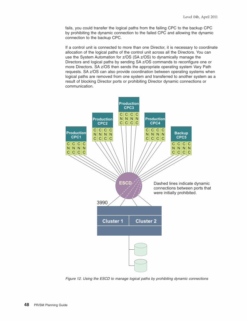
fails, you could transfer the logical paths from the failing CPC to the backup CPCby prohibiting the dynamic connection to the failed CPC and allowing the dynamicconnection to the backup CPC.
If a control unit is connected to more than one Director, it is necessary to coordinateallocation of the logical paths of the control unit across all the Directors. You canuse the System Automation for z/OS (SA z/OS) to dynamically manage theDirectors and logical paths by sending SA z/OS commands to reconfigure one ormore Directors. SA z/OS then sends the appropriate operating system Vary Pathrequests. SA z/OS can also provide coordination between operating systems whenlogical paths are removed from one system and transferred to another system as aresult of blocking Director ports or prohibiting Director dynamic connections orcommunication.
Figure 12. Using the ESCD to manage logical paths by prohibiting dynamic connections
Level 04b, April 2011
48 PR/SM Planning Guide

Shared channel overviewMIF allows channels to be shared among multiple LPs. Shared channels areconfigured to an LP giving the LP a channel image of the shared channel that it canuse. Each channel image allows an LP to independently access and control theshared channel as if it were a physical channel assigned to the LP.
By providing the logical equivalent of multiple physical channels dedicated tomultiple LPs, a shared channel can reduce hardware requirements without acorresponding reduction in I/O connectivity. This reduction in hardware requirementscan apply to physical channels, Director ports, and control unit ports, depending onthe configuration.
MIF requirementsTo take advantage of MIF, you need:
v An ESCON-capable operating system:– z/OS– z/VM– z/VSE– AIX/ESA®
– TPF– z/TPF
v ESCON channels operating in native mode (CNC) or channel-to-channel mode(CTC), FICON channels attached to an ESCON director (FCV), FICON channels(FC), coupling facility channels (ICP, CBP, CIB, or CFP), open systems adapterchannels (OSC, OSD, OSE or OSN), internal queued direct communication(HiperSockets) channels (IQD), and fibre channel protocol channels (FCP).
Note: ESCON channels that attach to a 9034 ESCON Converter Model 1 (CVCor CBY) cannot be shared among LPs.
v IBM ESCON-capable or FICON-capable control units, or fibre channel switches.
Understanding ESCON and MIF topologiesThis section describes the following I/O topologies:v Point-to-point topologyv Switched point-to-point topologyv MIF channel sharing topology
Point-to-Point Topology: The traditional point-to-point topology requires a uniquepath between any two points that communicate. A channel and CU adapter arerequired between each communication point. In a point-to-point configuration, achannel can communicate with only one control unit. A control unit thatcommunicates with more than one channel requires a separate control unit adapterinterface to each channel. The configuration limitations in a point-to-point topologycan lead to inefficient use of channels and control units. See Figure 13 on page 50for an example of the point-to-point topology.
Switched Point-to-Point Topology: Switched point-to-point topologies eliminatethe disadvantages of point-to-point and multidrop topologies. Switched point-to-pointtopology enables switching between any channel path and control unit adapterwhen using an ESCON or FICON Director. By using the Director, paths can also beshared by multiple points. The Director enables one channel to switch to multiplecontrol units, or one control unit to switch to multiple channels. Paths necessary tosatisfy connectivity requirements in a point-to-point topology are not required in theswitched point-to-point topology. This results in a reduction of the number of
Level 04b, April 2011
Chapter 2. Planning considerations 49

channels and control unit interfaces required without a corresponding reduction inI/O activity. See Figure 13 for an example of switched point-to-point topology.
MIF Channel Sharing Topology: MIF further improves control unit connectiontopologies for CPCs with multiple LPs. MIF enables many LPs to share a physicalchannel path. MIF can reduce the number of channels and control unit interfacesrequired without a corresponding reduction in I/O connectivity. See Figure 13 forand example of MIF channel sharing topology.
MIF performance planning considerationsYour installation can take advantage of MIF performance enhancements offered by:v Understanding and using I/O-busy management enhancementsv Planning for concurrent data transferv Understanding examples of MIF consolidation
Understanding and using I/O-busy management enhancements: This sectionshows how the various ESCON or FICON and MIF topologies offer improvementsin managing I/O-busy conditions. Figure 13 compares the point-to-point, switchedpoint-to point, and MIF channel sharing topologies.
Point-to-Point topologies: Concentrate I/O attempts at the control unit level and aredistance-dependent. At the time of a control unit busy encounter, the control unitmust present control unit busy status to the channel. Once the control unit is free, itpresents a control unit no longer busy status to the channel. This process ofpresenting status to the channel requires control unit processing and many tripsover the control unit to channel link.
Figure 13. Progression of busy condition management improvements
Level 04b, April 2011
50 PR/SM Planning Guide

Switched Point-to-Point topologies: Concentrate I/O attempts within the Directorand therefore encounter switch port busies. The processing of switch port busiesdoes not require any control unit involvement. Busies are handled by the ESCON orFICON Director. Therefore, the control unit is effectively relieved of handling busyconditions and is able to handle more I/O requests. Because switch port busiesrequire fewer trips over the ESCON or FICON connection link, they are lesssensitive to increased distances than control unit busy encounters.
MIF channel sharing: Moves busy management back into the channel subsystem,providing the most efficient management of busy conditions. Because multiple LPsaccess the same physical channel, I/O attempts are concentrated at the channellevel. A CU busy or a switch port busy is handled as a channel busy.
Planning for concurrent data transfer: Before you can consolidate channels,you must be aware of the channel requirements of the particular control units youare configuring. Table 7 shows the maximum recommended ESCON channels for asingle system going to a control unit. The number of channels needed isindependent of the number of LPs on a system. The number of channels is basedon the number of concurrent data transfers the control unit can handle. Although therecommended number of channels satisfies connectivity and performancerequirements, additional channels can be added for availability.
Table 7. MIF maximum channel requirements
Control unit typeMaximum channels
(see note)
9343 storage controller9343 D049343 DC4
44
3990 storage control3990-23990-33990-6
444
3490 magnetic tape subsystem35903490 D31, D32, D33, D343490 C10, C11, C123490 A013490 A103490 A023490 A20
2111122
2074 console support controller2074 002 2
3174 establishment controller3174 12L (SNA only)3174 22L (SNA only)
11
Note: The recommended maximum channels given in this table are based on performanceand connectivity requirements and do not include channels for availability.
Understanding examples of MIF consolidation: The following examples providesome general guidelines to show how MIF can help you consolidate and usehardware resources more efficiently:
ESCON configurations: Figure 14 on page 52 shows how four shared ESCONchannels can replace 16 unshared (dedicated or reconfigurable) ESCON channels
Level 04b, April 2011
Chapter 2. Planning considerations 51

and use 12 fewer control unit ports.
ESCD configurations: Figure 15 on page 53 shows how shared ESCON channelscan reduce ESCD port requirements. In this example, two shared ESCON channelsreplace 10 unshared (dedicated or reconfigurable) ESCON channels and use eightfewer ESCD ports without a reduction in I/O connectivity.
Figure 14. Consolidating ESCON channels and ESCON control unit ports
Level 04b, April 2011
52 PR/SM Planning Guide

Figure 15. Consolidating ESCON channels and ESCD ports
Level 04b, April 2011
Chapter 2. Planning considerations 53

ESCON CTC Configurations: Figure 16 shows how shared ESCON channels canreduce the ESCON channel requirements for ESCON CTC configurations. In thisexample, the CPC requires CTC communications among all its LPs.
By using two shared ESCON CTC/CNC pairs (4 shared ESCON channels), youcan:
v Replace five unshared ESCON CTC/CNC pairs (10 unshared ESCON channels)and the ESCD used to connect them
v Provide full redundancy
I/O connectivity is maintained while hardware requirements (channels and anESCD) are reduced.
Figure 16. Consolidating ESCON channels used for ESCON CTC communications
Level 04b, April 2011
54 PR/SM Planning Guide

In situations where ESCON CTC communication is required among LPs that existon two or more CPCs, shared channels can reduce even further channel and otherhardware requirements and their associated cost.
ESCON CTC configurations are well-suited to take advantage of the consolidationbenefits associated with shared channels. CTC/CNC and CTC/FCV pairs used forESCON CTC communications have no limitation on the number of logical paths thatcan be established between them. The only limitations are the number of controlunits that can be defined for an ESCON CTC channel and the performanceexpectations you determine for your configuration.
Infrequently Used ESCON or FICON Control Units: ESCON or FICON control unitsnot frequently used can use shared channels. You can attach such a control unit toa shared channel that is also attached to other, more frequently used control unitswithout adding greatly to the channel utilization of the shared channel. A goodexample is the control unit within the Director.
Notes:
1. You cannot define a control unit (or multiple control units with common I/Odevices) to a mixture of shared and unshared channel paths in the sameIOCDS.
2. You cannot define more than one control unit with the same CUADD to thesame link on a Director (or point-to-point) if the attaching CHPIDs are shared.
Unshared ESCON or FICON channel recommendationsNot all ESCON or FICON configurations benefit from the use of shared channels.There are some configurations where use of an unshared channel is moreappropriate. Consider the following:
v Logical path limitations of the control Unit
While many ESCON control units can communicate with multiple LPs at a timeusing multiple logical paths, there are some ESCON-capable control units thatcan only communicate with one LP at a time. For example, consider the 3174Establishment Controller (Models 12L and 22L). When configured in non-SNAmode, the 3174 establishes only one logical path at a time. A shared channelwould offer no connectivity benefit in this situation. However, if you defined anunshared, reconfigurable channel to the 3174, it would allow you to dynamicallyreconfigure the channel for any LP that had to communicate with the 3174 at agiven time.
v Channel Utilization
Typically, the channel utilization of shared channels is greater than unsharedchannels.
If you use shared channels to consolidate channel resources, you must considerthe channel utilization of all the channels you consolidate. The channel utilizationof a shared channel roughly equals the sum of the channel utilizations of eachunshared channel that it consolidates. If this total channel utilization coulddecrease performance, consider using unshared channels or a differentconfiguration of shared and unshared channels to meet your connectivity needs.
Dynamically managed CHPIDsA key aspect of the Intelligent Resource Director (IRD) provided by the WLMcomponent of z/OS is Dynamic CHPID Management (DCM). DCM provides theability to have the system automatically move the available channel bandwidth to
Level 04b, April 2011
Chapter 2. Planning considerations 55

where it is most needed. CHPIDs identified as managed in the IOCDS (by usingCHPARM and IOCLUSTER keywords) are dynamically shared among z/OS imageswithin an LPAR cluster.
Before DCM, available channels had to be manually balanced across I/O devices inan attempt to provide sufficient paths to handle the average load on everycontroller. Natural variability in demand means that some controllers at times havemore I/O paths available than they need, while other controllers possibly have toofew. DCM attempts to balance responsiveness of the available channels maximizingthe utilization of installed hardware. Fewer overall channels are required becausethe DCM CHPIDs are more fully used. RMF provides a report showing the averageaggregate utilization for all managed channels.
By using DCM, you now only have to define a minimum of one nonmanaged pathand up to seven managed paths to each control unit (although a realistic minimumof two nonmanaged paths are recommended), with dynamic channel pathmanagement taking responsibility for adding additional paths as required. For moreinformation about defining and using DCM, including detailed examples, see thez/OS Intelligent Resource Director, SG24-5952.
IOCP coding specificationsICP IOCP can only generate an LPAR IOCDS. No IOCP invocation parameter isrequired to generate an LPAR IOCDS.
IOCP statements for ICPThe RESOURCE statement is used to specify all the logical partition names definedin a machine configuration. To plan for growth in the number of logical partitions inthe configuration, one or more asterisks (*) might be used to specify that one ormore logical partitions are to be reserved along with their associated CSS and MIFimage IDs. A reserved LP can only be specified for a dynamic-capable IOCDS. Adynamic-capable IOCDS is built when using HCD on z/OS or z/VM or specifyingIOCP CMS utility option DYN for z/VM. Space in the hardware system area (HSA)is allocated for reserved LPs but cannot be used until a dynamic I/O configurationchange is made to assign a name to the LP. The following rules apply whenspecifying reserved LPs:
v A reserved LP must have a user-specified MIF image ID
v A reserved LP cannot have any channel paths assigned to it
v An IOCDS cannot contain only reserved LPs. At least one LP must be definedwith a name.
Dynamic CHPID Management (DCM) channel paths defined for a given LPARcluster are shareable among all active LPs that have joined that cluster. Other thanDCM channel paths, you must assign each channel path to a logical partition in anLPAR IOCDS. For each DCM channel path, ICP requires the CHPARM keywordhave a value of 01 and the IOCLUSTER keyword on a CHPID statement. All otherchannel paths require the PART|PARTITION, NOTPART, or SHARED keyword onall CHPID statements unless a channel path is defined as spanned by specifyingmultiple CSS IDs in the PATH keyword of the IOCP CHPID statement.
Use the CHPARM and IOCLUSTER keywords on the CHPID statement to specifychannel paths reserved for the use of a particular LPAR cluster. A DCM channelpath becomes available to a candidate logical partition when the LP is activated andjoins the specified cluster.
Level 04b, April 2011
56 PR/SM Planning Guide

Use the CHPID PART|PARTITION, NOTPART, and SHARED keywords todetermine which:v Channel paths are assigned to each LPv Devices and control units are shared among LPsv Channel paths are reconfigurablev Channel paths are shared
Use the CHPID CPATH keyword to connect two internal coupling channels.
Use the CHPID PATH keyword to define a channel path as spanned to multipleCSSs. Spanned channel paths are also shared channel paths.
DCM channel paths are implicitly shared. Use of the IOCLUSTER keyword impliesa null access list (no logical partition has the channel path brought online atactivation) and a candidate list of all defined logical partitions. The IOCLUSTERkeyword is mutually exclusive with the PART|PARTITION and NOTPART keywords.
All LP names that you specify in the CHPID statements must match the namesspecified in the RESOURCE statement. An IOCDS must have at least one LP namedefined.PARTITION={(CSS(cssid),{name|0}[,REC])|
(CSS(cssid),access list)|(CSS(cssid),(access list)[,(candidate list)][,REC])|
((CSS(cssid),(access list)[,(candidate list)]),...)}
NOTPART={(CSS(cssid),access list)|((CSS(cssid),(access list)[,(candidate list)]),...)}
IOCLUSTER=cluster_name
SHARED
CPATH=(CSS(cssid),chpid number)
Where:
name specifies the name of the LP that has authority to access theCHPID. The LP name is a 1–8 alphanumeric (0–9, A–Z) charactername that must have an alphabetic first character. Specialcharacters ($, #, @) are not allowed. A reserved LP cannot haveany channel paths assigned to it.
The following words are reserved and you cannot use them as LPnames:
PHYSICALRECSYSTEMPRIMnnnn (where nnnn are digits)
ICP IOCP supports a maximum of 60 LP names for the CPC.
cluster_name specifies the name of an LPAR cluster that has authority to accessthe specified DCM CHPID. The name of the LPAR cluster is a one-to eight- alphanumeric character name (0-9, A-Z) that must have analphabetic first character. Special characters ($, #, @) are notallowed.
REC specifies that the CHPID is reconfigurable. A reconfigurable CHPIDmust have an initial access list of one LP name. Its candidate listmust consist of one or more LP names.
Level 04b, April 2011
Chapter 2. Planning considerations 57

access list specifies the LPs that have initial access to the CHPID at thecompletion of the initial power-on reset. An LP name can onlyappear once in an access list.
You can specify that no LPs access the channel path following LPactivation for the initial POR of an LPAR IOCDS. Specifying 0indicates a null access list.
candidate list specifies the LPs that have authority to access the CHPID. Any LPthat is not in a CHPIDs candidate list cannot access the CHPID.
You can specify as many LP names as your CPC supports.However, the number of unique LP names specified in both theaccess list and candidate list can not exceed the number of LPsyour CPC supports.
If you specify the candidate list, you do not need to specify againthe LP names specified in the initial access list. The initial accesslist is always included in the candidate list.
An LP name can only appear once in a candidate list. If thecandidate list is not specified, it defaults to all LPs in theconfiguration for reconfigurable and shared channels.
Note: It is highly recommended that a peer mode CHPID (CBP, CFP, CIB, or ICP)have at most one coupling facility LP specified in its initial access list in orderto avoid confusion on subsequent LP activations. A peer mode CHPID canbe online to only one coupling facility LP at a time.
Using the SHARED keyword specifies that the channel paths on the CHPIDstatement are shared. More than one LP, at the same time, can access a sharedCHPID. When CHPIDs are not shared, only one LP can access it. Although you candynamically move a reconfigurable CHPID between LPs, it can only be accessed by1 LP at any given time. CVC and CBY channel paths (TYPE keyword) cannot beshared. On CF only models, CBP, CFP, and ICP channel paths cannot be shared.
The CPATH keyword is only valid for ICP and CIB channel paths (TYPE keyword)and required for all ICP and CIB definitions. CPATH specifies the connectionbetween 2 ICPs at either end of a coupling link:PATH=FE,TYPE=ICP,CPATH=FF,...PATH=FF,TYPE=ICP,CPATH=FE,...
specifies that ICP channel path FF connects to ICP channel path FE. Every ICPchannel path of a coupling facility must be connected to an ICP channel path of az/OS LP. The connection needs to be specified for each channel path. ICP channelpaths cannot connect to each other if they both have candidate lists with the same,single logical partition. This restriction prevents the definition of internal couplingchannels in an LPAR configuration with only one logical partition. Also, an ICPchannel path cannot connect to itself.
The CPATH value for a CIB CHPID specifies the CSS and CHPID number this CIBCHPID connects with on the target system. For example:PATH=C0,TYPE=CIB,CPATH=(CSS(1),D0),...
Defines a CIB CHPID, C0, on this system that connects with CIB CHPID D0 in CSS1 on the remote system.
Level 04b, April 2011
58 PR/SM Planning Guide

Shared devices using shared channelsMIF allows you to use shared channels when defining shared devices. Usingshared channels reduces the number of channels required, allows for increasedchannel utilization, and reduces the complexity of your IOCP input.
Note: You cannot mix shared and unshared channel paths to the same control unitor device.
Following is an example of an IOCDS with a shared device.
Following is the IOCP coding for Figure 17.CHPID PATH=(30),TYPE=CNC,SWITCH=03,SHARED . . .CHPID PATH=(34),TYPE=CNC,SWITCH=03,SHARED . . .CNTLUNIT CUNUMBR=000,PATH=(30,34),UNITADD=((90)),LINK=(E0,E0),UNIT=xxx . . .IODEVICE ADDRESS=(190),CUNUMBR=000,UNIT=xxx . . .
Shared devices using unshared channelsWhen coding an IOCP input file, the following specifications are allowed:
v Duplicate device numbers can be specified within a single IOCP input file, ifdevice numbers are not duplicated within an LP.
v You can assign a maximum of eight channel paths from each LP to a device.
Device sharing among LPs is accomplished by attaching multiple channel pathsfrom each LP to a device.
The following section illustrates IOCP coding for IOCDSs when shared devices onunshared channels and duplicate device numbers are specified.
Shared devices: The following examples illustrate this concept by showing thephysical connectivity of an I/O configuration for multiple LPs and the IOCP codingfor the same configuration.
Using channels: Figure 18 on page 60 shows an example of an I/O configurationwith a device shared by each of the four logical partitions. In this representation of ashared device, each logical partition views device 190 as part of its own I/O
Figure 17. Shared devices using shared ESCON channels
Level 04b, April 2011
Chapter 2. Planning considerations 59

configuration. Notice the recoverability characteristics of this configuration: eachlogical partition has two channel paths to the shared device, each attached to adifferent storage director.
The following example shows the IOCP statement for Figure 18.CHPID PATH=(10),PART=(A,REC)CHPID PATH=(14),PART=(A,REC)CHPID PATH=(18),PART=(B,REC)CHPID PATH=(1C),PART=(B,REC)CHPID PATH=(20),PART=(C,REC)CHPID PATH=(24),PART=(C,REC)CHPID PATH=(28),PART=(D,REC)CHPID PATH=(2C),PART=(D,REC)CNTLUNIT CUNUMBR=0001,PATH=(10,18,20,28),UNITADD=((90)) . . .CNTLUNIT CUNUMBR=0002,PATH=(14,1C,24,2C),UNITADD=((90)) . . .IODEVICE ADDRESS=(190),CUNUMBR=(0001,0002) . . .
If 8 or less channels attach to the device, this method of defining the IOCP inputprovides greater flexibility because it allows you to move CHPIDs from one LP toanother and eliminates possible conflicts (see Figure 21 on page 63).
Figure 19 on page 61 shows an alternative method of defining the configuration.This method is required if there are greater than eight paths to the device. Thislogical representation has the same recoverability characteristics as the physicalconnectivity:v Each LP has two channel paths to the shared devicev Each LP is attached to a different storage director
Figure 18. Physical connectivity of shared device 190
Level 04b, April 2011
60 PR/SM Planning Guide

However, paths cannot be moved between the LPs.
The following example shows the IOCP statement for Figure 19.CHPID PATH=(10),PARTITION=(A), . . .CHPID PATH=(14),PARTITION=(A), . . .CNTLUNIT CUNUMBR=0001,PATH=(10),UNITADD=((90)) . . .CNTLUNIT CUNUMBR=0002,PATH=(14),UNITADD=((90)) . . .IODEVICE ADDRESS=(190),CUNUMBR=(0001,0002) . . .
CHPID PATH=(18),PARTITION=(B), . . .CHPID PATH=(1C),PARTITION=(B), . . .CNTLUNIT CUNUMBR=1001,PATH=(18),UNITADD=((90)) . . .CNTLUNIT CUNUMBR=1002,PATH=(1C),UNITADD=((90)) . . .IODEVICE ADDRESS=(190),CUNUMBR=(1001,1002) . . .
CHPID PATH=(20),PARTITION=(C) . . .CHPID PATH=(24),PARTITION=(C) . . .CNTLUNIT CUNUMBR=2001,PATH=(20),UNITADD=((90)) . . .CNTLUNIT CUNUMBR=2002,PATH=(24),UNITADD=((90)) . . .IODEVICE ADDRESS=(190),CUNUMBR=(2001,2002) . . .
CHPID PATH=(28),PARTITION=(D), . . .CHPID PATH=(2C),PARTITION=(D), . . .CNTLUNIT CUNUMBR=3001,PATH=(28),UNITADD=((90)) . . .CNTLUNIT CUNUMBR=3002,PATH=(2C),UNITADD=((90)) . . .IODEVICE ADDRESS=(190),CUNUMBR=(3001,3002) . . .
Duplicate device numbers for different physical devicesFigure 20 on page 62 illustrates a configuration where duplicate device numbers areused to represent a console (110) and a printer (00E) within each of four logicalpartitions.
Figure 19. Logical view of shared device 190
Level 04b, April 2011
Chapter 2. Planning considerations 61

The following example shows the IOCP statement for Figure 20. This IOCP codingexample groups the input statements by logical partition. When coding IOCP, viewthe I/O devices from a logical partition perspective.CHPID PATH=(10),PARTITION=(A), . . .CHPID PATH=(14),PARTITION=(A), . . .CNTLUNIT CUNUMBR=0011,PATH=(10),UNITADD=(10), . . .CNTLUNIT CUNUMBR=0012,PATH=(14),UNITADD=(0E), . . .IODEVICE ADDRESS=(110),CUNUMBR=(0011), . . .IODEVICE ADDRESS=(00E),CUNUMBR=(0012), . . .
CHPID PATH=(18),PARTITION=(B), . . .CHPID PATH=(1C),PARTITION=(B), . . .CNTLUNIT CUNUMBR=0013,PATH=(18),UNITADD=(10), . . .CNTLUNIT CUNUMBR=0014,PATH=(1C),UNITADD=(0E), . . .IODEVICE ADDRESS=(110),CUNUMBR=(0013), . . .IODEVICE ADDRESS=(00E),CUNUMBR=(0014), . . .
CHPID PATH=(20),PARTITION=(C), . . .CHPID PATH=(24),PARTITION=(C), . . .CNTLUNIT CUNUMBR=0015,PATH=(20),UNITADD=(10), . . .CNTLUNIT CUNUMBR=0016,PATH=(24),UNITADD=(0E), . . .IODEVICE ADDRESS=(110),CUNUMBR=(0015), . . .IODEVICE ADDRESS=(00E),CUNUMBR=(0016), . . .
CHPID PATH=(28),PARTITION=(D), . . .CHPID PATH=(2C),PARTITION=(D), . . .CNTLUNIT CUNUMBR=0017,PATH=(28),UNITADD=(10), . . .CNTLUNIT CUNUMBR=0018,PATH=(2C),UNITADD=(0E), . . .IODEVICE ADDRESS=(110),CUNUMBR=(0017), . . .IODEVICE ADDRESS=(00E),CUNUMBR=(0018), . . .
Eight IODEVICE statements are used, one for each console and one for eachprinter that has a duplicate device number. Device numbers 110 and 00E occur fourtimes each; however, they are not duplicated within a logical partition. When codingan IOCP input file, remember that the unique device number rule applies for logicalpartitions in an IOCDS.
LogicalPartition
A
LogicalPartition
B
LogicalPartition
C
LogicalPartition
D
CHP10
110 110 110 110
00E00E00E00E
CHP18
CHP20
CHP28
CHP14
CHP1C
CHP24
CHP2C
Figure 20. LPAR configuration with duplicate device numbers
Level 04b, April 2011
62 PR/SM Planning Guide

Figure 21 shows another example of a logical partition configuration in which thedevice number for a console (110) is duplicated for all four logical partitions.
The following example shows the IOCP coding for the previous configuration. FourIODEVICE and four CNTLUNIT statements are used, one each for the consolewithin each logical partition that has a duplicate device number.CHPID PATH=(10),PARTITION=(A), . . .CHPID PATH=(14),PARTITION=(A), . . .CNTLUNIT CUNUMBR=0001,PATH=(10,14),UNITADD=((10)), . . .IODEVICE ADDRESS=(110),CUNUMBR=(0001), . . .
CHPID PATH=(18),PARTITION=(B), . . .CHPID PATH=(1C),PARTITION=(B), . . .CNTLUNIT CUNUMBR=0002,PATH=(18,1C),UNITADD=((10)), . . .IODEVICE ADDRESS=(110),CUNUMBR=(0002), . . .
CHPID PATH=(20),PARTITION=(C), . . .CHPID PATH=(24),PARTITION=(C), . . .CNTLUNIT CUNUMBR=0003,PATH=(20,24),UNITADD=((10)), . . .IODEVICE ADDRESS=(110),CUNUMBR=(0003), . . .
CHPID PATH=(28),PARTITION=(D), . . .CHPID PATH=(2C),PARTITION=(D), . . .CNTLUNIT CUNUMBR=0004,PATH=(28,2C),UNITADD=((10)), . . .IODEVICE ADDRESS=(110),CUNUMBR=(0004), . . .
Duplicate device number conflicts: IOCP allows duplicate device numbers in anIOCDS only if the duplicate device numbers do not occur in the same logicalpartition. Therefore, IOCP allows systems to use different logical partitions tointegrate a processor complex without changing device numbers.
IOCP requires a unique device number for each device within a logical partition.When IOCP completes without error, the initial configuration contains no duplicatedevice number conflicts within a logical partition.
Conflicts can occur when the I/O configuration is modified. If a channel path isconfigured to a logical partition and devices attached to the channel path havedevice numbers that are already assigned in the receiving logical partition to otheronline channel paths, a conflict results.
Figure 21. Duplicate device numbers for console
Level 04b, April 2011
Chapter 2. Planning considerations 63

When an I/O configuration is dynamically modified so the logical partition can gainaccess to a device not previously accessible, a device conflict can occur. Theconflicts are detected when commands are processed that change the I/Oconfiguration or when you attempt to activate the logical partition which has thedevice number conflict. A message displays identifying the error.
The identified device cannot be accessed while a conflict exists. Two types ofconflict are possible:v Conflicts between device numbers for the same device (a shared device)v Conflicts between device numbers for different devices (unshared devices)
Activation fails if a duplicate device number conflict exists.
Examples of duplicate device number conflicts: Figure 22 provides twoexamples of duplicate device number conflict.
The following example shows the IOCP statement for Figure 22. Both examples useidentical IOCP statements.CHPID PATH=(00),PARTITION=(ZOSPROD,REC)CHPID PATH=(04),PARTITION=(ZOSPROD,REC)CNTLUNIT CUNUMBR=0001,PATH=(00,04),UNITADD=80IODEVICE ADDRESS=180,CUNUMBR=0001
CHPID PATH=(10),PARTITION=(ZOSTEST)CNTLUNIT CUNUMBR=0002,PATH=(10),UNITADD=80IODEVICE ADDRESS=180,CUNUMBR=0002
Channel path 04 is reassigned from ZOSPROD to ZOSTEST in each example. Thisreassignment creates a duplicate device number conflict for device number 180when the devices are connected to two different control units. This conflict occursbecause a device numbered 180 exists on the original channel path 10. If suchconflicts occur, the operator must know what configuration is wanted.
Shared deviceIn the example on the left, the duplicate device numbers refer to thesame device from different logical partitions (a new path to thesame device has been moved to ZOSTEST). This situation mightresult in a performance problem because the control program inlogical partition OS390 cannot access the device from channel path4.
ZOSPROD ZOSPROD
Device 180
Example, Shared Device Example, Unshared Device
CHP00
CHP04
CHP00
CHP04
CHP04
CHP10
CHP04
CHP10
Device 180 Device 180
ZOSTEST ZOSTEST
Figure 22. Two examples of duplicate device number conflicts
Level 04b, April 2011
64 PR/SM Planning Guide

Unshared DeviceIn the example on the right, the duplicate device numbers refer to adifferent device from each logical partition (a new device has beenmoved to ZOSTEST). This situation might result in a data integrityproblem because the control program in logical partition ZOSTESTcannot access the correct device from channel path 04.
Resolving duplicate device number conflicts: Consider options A, B, and Cwhen planning the I/O configuration and the reconfigurability of channel paths. Youcan resolve duplicate device number conflicts by choosing one of the options:
A Use the original channel path:
If the receiving logical partition does not need a new path to a shareddevice or does not need the new (unshared) device, take no action. Theconflict is resolved by using only the original path (shared device) or theoriginal device. (Access is still allowed to any nonconflicting devices on thenewly configured channel path.)
In Figure 22 on page 64, ZOSTEST can access device 180 only throughchannel path 10 if the operator takes no action in response to the conflictmessage.
B Deconfigure the original channel path:
If the logical partition must have the reassigned channel path to a shareddevice or access to a new (unshared) device, the conflict is resolved bysubstituting the reassigned channel path for the original channel path. Dothe following:
1. Configure offline the original channel path (CHP 10 in Figure 22).
2. Configure offline and then online the reassigned channel path (CHP 04in Figure 22).
3. If necessary, configure online the original channel path (CHP 10 inFigure 22). Another conflict message is issued because a new conflicthas been created. The operator then ignores this conflict as describedin option A. (Access is still allowed to any nonconflicting devices on theoriginal channel path.)
In Figure 22, ZOSTEST can access device 180 only through channel path04 if the preceding steps are performed in response to the conflictmessage.
C Change the I/O configuration:
Only option C provides a permanent resolution to a device number conflict.
If the logical partition must have access to all devices over the originalchannel path and the reassigned channel path (shared devices), or to anew device and the original device (unshared devices), do one of thefollowing:
v Create a configuration with unique device numbers, if they are unshareddevices.
v For shared devices, define a single device with access to all the channelpaths attached to the physical control units.
v For a shared device assigned to unshared channel paths, change thechannel paths to shared and consolidate the control units and devicedefinitions to one each.
v If the device is assigned to shared channel paths, control access to thedevices using their device candidate list.
Level 04b, April 2011
Chapter 2. Planning considerations 65

The configuration can be activated by performing a POR or by performing adynamic I/O configuration.
In Figure 22 (shared device), ZOSTEST can access device 180 throughCHP 04 and CHP 10 if CHP 04 is defined to ZOSTEST in the IOCDS.
In Figure 22 (unshared device), ZOSTEST can access either device 180(unshared device) if one or both of the devices are assigned a new devicenumber in the IOCDS.
When a device number conflict exists, logical partitions fail to activate. Thishappens when one of the following conditions occurs:
v The receiving logical partition was deactivated when a channel path isreassigned
v The receiving logical partition is deactivated after a channel path is reassigned
Failure to activate can result if options A or B are used. If a logical partition fails toactivate, use option B or C to resolve the conflict and to activate the logicalpartition.
In Figure 22, if ZOSTEST is not active when CHP 04 is reassigned, or ZOSTEST isdeactivated and then activated after CHP 04 is reassigned, ZOSTEST does notactivate until the conflict over device 180 is resolved.
If you resolve the conflict by using option B do the following steps:
1. Establish the correct configuration by configuring offline one of the channelpaths (CHP 04 or CHP 10)
2. Configure offline and then online the other channel path
If it is necessary to have access to other devices on the first channel path, theoperator can configure online the first channel path while the LP is active. Ignorethe messages issued at the hardware console.
The following IOCP statement example shows coding that removes duplicate devicenumber conflicts for shared devices.CHPID PATH=(00),PARTITION=(ZOSPROD,REC), . . .CHPID PATH=(04),PARTITION=(ZOSPROD,REC), . . .CHPID PATH=(10),PARTITION=(ZOSTEST), . . .CNTLUNIT CUNUMBR=0001,PATH=(00,04),UNITADD=80CNTLUNIT CUNUMBR=0002,PATH=(10),UNITADD=80IODEVICE ADDRESS=180,CUNUMBR=(0001,0002)
Level 04b, April 2011
66 PR/SM Planning Guide

Coupling facility planning considerationsThe coupling facility provides shared storage and shared storage managementfunctions for the sysplex (for example, high speed caching, list processing, andlocking functions). Applications running on z/OS images in the sysplex define theshared structures used in the coupling facility.
The coupling facility allows applications, running on multiple z/OS images that areconfigured in a sysplex, to efficiently share data so that a transaction processingworkload can be processed in parallel across the sysplex.
PR/SM LPAR allows you to define the coupling facility, which is a special logicalpartition (LP) that runs coupling facility control code. Coupling facility control code isLicensed Internal Code (LIC).
At LP activation, coupling facility control code automatically loads into the couplingfacility LP from the Support Element hard disk. No initial program load (IPL) of anoperating system is necessary or supported in the coupling facility LP.
Coupling facility control code runs in the coupling facility LP with minimal operatorintervention. Operator activity is confined to the Operating System Messages task.PR/SM LPAR limits the hardware operator controls typically available for LPs toavoid unnecessary operator activity.
Coupling facility channel hardware provides the connectivity required for datasharing between the coupling facility and the CPCs directly attached to it. Couplingfacility channels are point-to-point connections that require a unique channeldefinition at each end of the channel. See “Coupling facility channels” on page 81.
Test or migration coupling configurationYou can run a test or migration coupling facility to test and develop data sharingapplications. You can define a test or migration coupling facility LP on the sameCPC where other LPs are:v Running z/OS images connected to the coupling facilityv Running non-coupled production work
A single CPC configuration has the following considerations:
v Simultaneous loss of the coupling facility and any z/OS images coupled to it (amore likely possibility in a single CPC configuration) can potentially causeextended recovery times
You can define a test or migration coupling facility with or without coupling facilitychannel hardware. See “Defining internal coupling channels (TYPE=ICP)” on page85 for information about how to define a test or migration facility without couplingfacility channel hardware.
CFCC Enhanced Patch ApplyWith the CFCC Enhanced Patch Apply, you can perform a disruptive install of newCFCC code on a test CF and run it, while a production CF image in the same CECremains at the base CFCC code level. Then when the test CF is successful, thenew CFCC code can be installed on the production CF. Both installations can bedone without a Power On Reset (POR) of the CEC.
Level 04b, April 2011
Chapter 2. Planning considerations 67

Production coupling facility configurationIBM recommends that you run your production applications on a sysplex that usesa production coupling facility configuration.
A properly configured production coupling facility configuration can reduce thepotential for extended recovery times, achieve acceptable performance, andmaximize connectivity to the coupling facility.
For production configurations, the use of one or more dedicated Coupling Facilityengines is recommended; shared Coupling Facility engines are stronglydiscouraged. For more information, see the Important Note on page 123.
Production coupling facility configuration for full data sharingThe preferred solution for a full data sharing (IMS™, DB2®, VSAM/RLS) productionparallel sysplex is a coupling facility configuration that consists of:
v One stand-alone coupling facility running as a single dedicated coupling facilityLP to provide large capacity shared storage and maximum coupling facilitychannel connectivity (up to 64 coupling facility channels).
v A second stand-alone coupling facility, similarly configured, to reduce thepossibility of a single point of failure. A second stand-alone coupling facilityimproves application subsystem availability by allowing fast recovery from onecoupling facility to the other in the event of a coupling facility outage.Alternatively, an Internal Coupling Facility (ICF) feature can be used to providethe backup coupling facility. See “Internal Coupling Facility (ICF)” on page 69.
Notes:
1. The backup CF in the configuration must provide sufficient storage, processor,and connectivity resources to assume the workload of the other production CFin the event of its failure.
2. With the use of System-Managed CF Structure Duplexing for all relevant datasharing structures, it is possible to have a production data-sharing configurationthat uses only 2 or more internal CFs, because duplexing avoids the “singlepoint of failure” failure-isolation issue.
Production coupling facility configuration for resource sharingA viable solution for a resource sharing (XCF Signaling, Logger Operlog, RACF®,BatchPipes®, Logger Logrec, Shared Tape, GRS, WLM Enclave Support, LPARClusters) production level parallel sysplex is a coupling facility configuration thatconsists of:
v One dedicated ICF provides reduced cost of ownership without compromisingsysplex availability or integrity.
v A second dedicated ICF reduces the possibility of a single point of failure. Asecond ICF improves application subsystem availability by allowing fast recoveryfrom one coupling facility to the other in the event of a coupling facility outage.
Note: The backup CF in the configuration must provide sufficient storage,processor, and connectivity resources to assume the workload of the otherproduction CF in the event of its failure.
These configurations offer the best performance, the best reliability, availability, andserviceability (RAS).
Level 04b, April 2011
68 PR/SM Planning Guide

Internal Coupling Facility (ICF)You can purchase and install one or more ICF features for use in coupling facilityLPs. With this feature, the coupling facility runs on special ICF CPs that nocustomer software can use. This feature allows the coupling facility function to beperformed on the CPC without affecting the model group and thus without impactingsoftware licensing costs for the CP resources used by the coupling facility. See“Considerations for coupling facilities using Internal Coupling Facility (ICF) CPs” onpage 123.
These features are ordered separately, and are distinguished at the hardware levelfrom any general-purpose CPs, Integrated Features for Linux (IFLs), IBM Systemz10 Application Assist Processor (zAAPs) features, and System z10 IntegratedInformation Processor (zIIPs). ICFs, IFLs, zAAPs, or zIIPs are perceived by thesystem as multiple resource pools.
With the CFCC Enhanced Patch Apply process, you can perform a disruptive installof new CFCC code on an ICF image by deactivating and then reactivating the CFimage, without the much greater disruption of a Power On Reset (POR) of theentire CEC that contains the CF image. Thus, availability is greatly improved.
Coupling facilities that reside on the same CEC as one or more z/OS parallelsysplex logical partitions are ideal for coupling resource sharing sysplexes(sysplexes that are not in production data sharing with IMS, DB2 or VSAM/RLS).You can simplify systems management by using XCF structures instead of ESCONCTC connections.
IBM does not recommend use of coupling facilities that reside on the same CEC asone or more z/OS parallel sysplex logical partitions for most coupling facilitystructures involved in data sharing because of the possibility of double outagesinvolving the simultaneous loss of a coupling facility image and one or more z/OSsystem images that are using the coupling facility for data sharing. Depending onthe structure, a double outage can result in a significantly more involved recoverythan a single outage of either a coupling facility image or a z/OS image in isolationfrom one another.
With the use of System-Managed CF Structure Duplexing for all relevant datasharing structures, it is possible to have a production data-sharing configuration thatuses only 2 or more internal CFs, because duplexing avoids the “single point offailure” failure-isolation issue.
ICFs on stand-alone coupling facilities need configuration planning to account forstorage and channels. ICFs likely increase storage requirements for the CPC withan ICF installed, especially if software uses the coupling facility to provide additionalfunction not available except when running a coupling facility in a parallel sysplex.
The following table indicates the maximum number of ICFs that you can install on agiven model.
CPC model Maximum number of ICFs supported
System z10 BCModel E10 10
Level 04b, April 2011
Chapter 2. Planning considerations 69

CPC model Maximum number of ICFs supported
System z10 ECModel E12Model E26Model E40Model E56Model E64
1216161616
Dynamic Coupling Facility Dispatching (DCFD)With DCFD, the coupling facility uses CP resources in a shared CP environmentefficiently, making a coupling facility using shared CPs an attractive option as aback-up coupling facility. Without DCFD, a coupling facility using shared CPs wouldattempt to get all the CP resource it could even when there was no real work for itto do. With dynamic coupling facility dispatching, the coupling facility monitors therequest rate that is driving it and adjust its usage of CP resource accordingly. If therequest rate becomes high enough, the coupling facility reverts to its originaldispatching algorithm, constantly looking for new work. When the request ratelowers, the coupling facility again becomes more judicious in its use of CPresource.
This behavior plays well into a hot-standby back-up coupling facility role. In back-upmode, the coupling facility has a very low request rate so it throttles back to verylow CP usage. In this mode, the requests themselves experience some elongationin response time but this delay does not adversely affect the performance of theoverall system. Since the coupling facility is not consuming more CP resource thanit needs to, you can now set the processor weights for the coupling facility to avalue high enough to handle the load if the coupling facility was to take over for afailing primary coupling facility. If the primary coupling facility does fail, the requestscan be moved immediately to the back-up coupling facility which can then get theCP resource it needs automatically with properly defined LP weights.
Dynamic coupling facility dispatching is particularly useful in configurations whereless than one CP of capacity is needed for use by the back-up coupling facility.Dynamic coupling facility dispatching is automatically enabled for any couplingfacility LP that uses shared CPs, except for stand-alone coupling facilities. Toenable dynamic coupling facility dispatching on stand-alone coupling facilities, usethe DYNDISP coupling facility control code command. See “Coupling facility controlcode commands” on page 76. It is recommended that anytime a shared processoris used for a coupling facility, whether standalone or ICF processors, that DCFD beenabled by ensuring that the DYNDISP coupling facility control command is set toON.
Note: It is only for the first activation of a CF logical partition that the DCFD is tobe automatically enabled. Once it is activated, the DYNDISP setting isrecorded in the policy file for that CF logical partition. The DYNDISP settingis to be preserved and the subsequent activations are based on theDYNDISP setting recorded in the CF policy file. So, if the CF image profile isupdated later to use shared CPs, the DCFD will not be automaticallyenabled. It needs to be enabled using the DYNDISP coupling facility controlcode command.
Level 04b, April 2011
70 PR/SM Planning Guide

CouplingFacility
Configuration
All DedicatedCPs or ICFs
Shared ICF Shared CP Shared ICF
CF Model -System z10 with
only ICFprocessors
System z10 with1 or more
general-purposeCPs
System z10 with1 or more
general-purposeCPs
DynamicDispatching
Default ValueOff Off On Off
System-managed coupling facility structure duplexingA set of parallel sysplex architectural extensions is provided for support ofsystem-managed duplexing of coupling facility structures for high availability. Allthree structure types, cache, list, and locking, can be duplexed using thisarchitecture.
Benefits of system-managed CF structure duplexing include:
v Availability: Faster recovery of structures by having the data already in thesecond CF.
v Manageability and Usability: A consistent procedure to set up and managestructure recovery across multiple exploiters
v Cost Benefits: Enables the use of non-standalone CFs (for example, ICFs) forall resource sharing and data sharing environments.
Preparations for CF duplexing include the requirement to connect coupling facilitiesto one another with coupling links. The required CF-to-CF connectivity isbi-directional, so that signals can be exchanged between the CFs in both directions.A single peer-mode coupling link between each pair of CFs can provide therequired CF-to-CF connectivity; however, for high availability at least two peer-modelinks between each pair of CFs are recommended.
While peer-mode CHPIDs cannot be shared between multiple coupling facilityimages, they can be shared between a single coupling facility image and one ormore z/OS images. With this sharing capability, a single peer-mode ISC-3 or ICBlink can serve both as a z/OS-to-CF link and as a CF-to-CF link, and thus providethe connectivity between z/OS and CF partitions as well as the connectivitybetween CFs that is required for CF Duplexing. At least two such links isrecommended for high availability. In addition, IFB links can provide the ability toactually share the same physical link between multiple CF images. By definingmultiple CHPIDs on the same physical IFB link, the individual CHPIDs can bedefined for a single CF image while the physical link is being shared by multiple CFimages.
Coupling Facility Level 16 duplexing enhancementsBefore Coupling Facility Control Code (CFCC) Level 16, System-Managed CouplingFacility (CF) Structure Duplexing required two duplexing protocol exchanges tooccur synchronously during processing of each duplexed structure request. CFCCLevel 16 allows one of these protocol exchanges to complete asynchronously. Thischange allows faster duplexed request service time, with more benefits when theCoupling Facilities are further apart, such as in a multi-site Parallel Sysplex.
Level 04b, April 2011
Chapter 2. Planning considerations 71

Single CPC software availability sysplexFor single CPC configurations, System z10 models can use an ICF to form a singleCPC sysplex, providing significant improvement in software continuous operationscharacteristics when running two z/OS LPs in data-sharing mode versus one largez/OS image. For these configurations, overall RAS is improved over that providedby a single z/OS image solution. Hardware failures can take down the entire singleCPC sysplex, but those failures are far less frequent than conditions taking down asoftware image, and planned software outages are the predominant form ofsoftware image outages in any case. Forming a single CPC sysplex allows softwareupdates to occur in a “rolling” IPL fashion, maintaining system availabilitythroughout. An LPAR cluster is one example of a single CPC sysplex which hassignificantly improved system availability over a single LP. For additional benefitsprovided by an LPAR cluster using IRD technology, see z/OS Intelligent ResourceDirector, SG24-5952.
Coupling facility nonvolatilityContinuous availability of the transaction processing workload in a coupling facilityconfiguration requires continuous availability of the shared structures in the couplingfacility. To help ensure this availability, you must provide an optional backup powersupply to make coupling facility storage contents nonvolatile across utility powerfailures.
Nonvolatility choicesThe following table indicates the optional nonvolatility choices available and theircapabilities:
Table 8. Nonvolatility choices for coupling facility LPs
Nonvolatility Choices z10 BC z10 EC
Uninterruptible power supply (UPS) (See Notes ¹) Yes Yes
Internal Battery Feature (IBF) Yes Yes
Local Uninterruptible Power Supply (LUPS) (See Notes ²) Yes Yes
Notes:
1. Optional uninterruptible power supply (UPS) provides a secondary power source for useduring extended utility power outages allowing continuous coupling facility operation.
2. The optional Local Uninterruptible Power Supply supports 0 - 18 minutes of full poweroperation.
Setting the conditions for monitoring coupling facilitynonvolatility statusIn addition to installing an optional backup power supply to help ensure continuousavailability, you must also set the conditions by which the coupling facilitydetermines its volatility status. Software subsystems with structures defined in thecoupling facility can monitor this status. Use the coupling facility control code MODEcommand as follows:
v MODE NONVOLATILE sets coupling facility volatility status to nonvolatile andshould be used if a floor UPS is available to the CPC. Coupling facility controlcode does not monitor the installation or availability of UPS but maintains anonvolatile status for the coupling facility.
v MODE VOLATILE sets coupling facility volatility status to volatile and should beused if no backup power supply is installed and available. Coupling facility controlcode maintains volatile status for the coupling facility even if a backup powersupply is installed and available.
Level 04b, April 2011
72 PR/SM Planning Guide

The coupling facility MODE setting is saved across power-on reset and activation ofthe coupling facility. You can use online help from the Operator Messages panel toget additional information about coupling facility control code commands.
Coupling facility mode settingThe following table summarizes the relationship between the coupling facility MODEsetting, and the resulting conditions you can expect if utility power fails at your site.
Table 9. Coupling facility mode setting
CF MODEsetting
Local UPSor IBF
installed Results on Utility Power Failure
VOLATILE Yes Ride out utility power failure on UPS/IBF. (Settingthe mode to VOLATILE here would be aconfiguration error because there is local UPS orIBF to provide nonvolatility.)
VOLATILE NoMachine down unless alternate floor level UPS/IBFprovided.
NONVOLATILE Yes Ride out utility power failure on UPS/IBF.
NONVOLATILE No
Machine down unless alternate floor level UPS/IBFprovided.Note: This is the recommended setting whenproviding floor-wide UPS/IBF backup.
Note: Reflects the real-time status of the power (volatile or nonvolatile).
Coupling facility LP definition considerationsYou can define coupling facility mode for an LP at the Hardware ManagementConsole or Support Element console using the Activation Profiles task availablefrom the CPC Operational Customization Tasks Area.
You can define coupling facility LPs with shared or dedicated CPs on all Systemz10 models. Coupling facility LPs must be defined with at least 128 MB of centralstorage. See Table 13 on page 106.
Coupling facility LPs do not support some LP definition controls typically availableto other LPs. For coupling facility LPs, you cannot define:
v Reserved central storage (coupling facility LPs do not support dynamic storagereconfiguration)
v Expanded storage initial or reserved amounts or expanded storage origin
v Crypto Express2 and/or Crypto Express3
v Automatic load
v Automatic load address
v Automatic load parameters
Internal Coupling Facility (ICF)You can install one or more internal coupling facility (ICF) features. See“Considerations for coupling facilities using Internal Coupling Facility (ICF) CPs” onpage 123.
Level 04b, April 2011
Chapter 2. Planning considerations 73

Coupling facility LP storage planning considerationsYou must define at least 512 MB of central storage for a coupling facility LP toactivate.
Note: 512 MB of central storage is required after installing DR79 - CFCC ECN24403 MCL009.
This storage is reserved for coupling facility control code use and cannot be usedfor other purposes. Minimum storage size for coupling facilities is primarily afunction of the coupling facility control code level. This implies that, over time, theminimum storage size required by a coupling facility on a particular machine cangrow as new coupling facility control code updates are applied.
You must also define additional storage to accommodate the shared structures anddump space used by software subsystems using the coupling facility.
If a hot standby back-up coupling facility is defined, you must allocate to theback-up coupling facility all the storage required by that coupling facility to handlethe structures it might need to hold in an active takeover role. Storage resources forcoupling facility LPs are static and must be allocated at LP activation time of thecoupling facility LP.
Structures, dump space, and coupling facility LP storageA coupling facility allocates storage for structures and for dump space based onvalues specified in the SIZE, INITSIZE, and DUMPSPACE parameters of thecoupling facility resource management (CFRM) policy used for the coupling facility.
Structures consist of control objects and data elements. The control objects includeentries and various other control structures used to manipulate the entries. The dataelements store user data associated with structure entries.
Dump space is storage in the coupling facility set aside for use as a dump tablewhen a structure dump is taken. Dump tables are used for application developmentand problem determination purposes.
The following table indicates the maximum central storage possible for the Systemz10 models:
Table 10. Maximum central storage for System z10 models
Models Maximum Central Storage (GB)
System z10 BCModel E10 120
System z10 ECModel E12Model E26Model E40Model E56Model E64
352752113615201520
Note: The maximum single partition size is 1 TB (1024 GB).
Estimating coupling facility structure sizesEstimating coupling facility structure sizes is useful to system programmers to helpensure that there is enough coupling facility storage to meet application needs. Theestimation of the minimum central storage requirements of your List or Cache
Level 04b, April 2011
74 PR/SM Planning Guide
|
||

structure has been superseded by the following two commands used by theCFSizer Utility to make space calculations in the coupling facility:
v Compute list-structure parameters: For computing the minimum centralstorage requirements for a List structure. (What z/OS calls lock structures areactually a special form of list structure.)
v Compute cache-structure parameters: For computing the minimum centralstorage requirements for a Cache structure.
IMPORTANT NOTEWhen implementing a new CFLEVEL in your configuration, redetermine thesize of List and Cache structures using the CFSizer Utility and update theCFRM policy with the newly acquired values. For more information about theCFSizer Utility, see the following link:
http://www.ibm.com/systems/support/z/cfsizer/
Dump space allocation in a coupling facilityDump space is storage you define using the DUMPSPACE parameter in thecoupling facility resource management (CFRM) policy. It is set aside for the creationof dump tables. Dump tables are portions or snapshots of a structure typicallysaved for application development or problem determination purposes. The couplingfacility allocates dump space in multiples of the coupling facility storage increment.
Dump tables for several different structures can exist in dump space at the sametime. The amount of storage in any one dump table depends on the followingfactors:
v Amount of information you want to save to a dump table
The software subsystem can request the portions of a structure that are to becaptured in the dump table. For example, lock tables, lists within a list structure,or directory entries belonging to particular storage classes or castout classes.
v Free dump space
Structures share dump space. If a structure is using some of the dump space,other structures cannot use that portion of the dump space until it is released.
v Characteristics of the structure saved to a dump table
When saving structure objects to a dump table, the amount of dump space useddepends on the parameters specified for the structure. For example, list entrysize, the number of list entries in a specified list, the number of directory entriesin a castout class, or whether adjunct data is included.
The coupling facility can return the maximum requested dump space value. Thisvalue indicates the largest amount of dump space requested by the softwaresubsystems using the coupling facility. This value allows you to adjust the amount ofallocated dump space to better match actual usage.
Coupling facility LP activation considerationsAt LP activation, coupling facility control code automatically loads into the couplingfacility LP from Support Element hard disk. No initial program load (IPL) of anoperating system is necessary or supported in the coupling facility LP.
All coupling facility channel path types targeted to be brought online areautomatically configured online.
Level 04b, April 2011
Chapter 2. Planning considerations 75

Note: All channel paths types that are targeted to be brought online willautomatically be configured online if the coupling facility LP is redefined asan ESA mode LP.
Coupling facility shutdown considerations
IMPORTANT NOTEIt is important to properly remove all structures from a coupling facility that willbe permanently taken out of the sysplex before shutting down the couplingfacility. Failure to remove all structures might result in a pending condition (ortransitioning structure) when attempting to allocate structures in a newcoupling facility. Reactivation of the old coupling facility might be required toresolve the condition.
A running coupling facility LP can contain structures and data important to asysplex. Make sure that you take proper precautions to preserve these structuresand data before a power off, power-on reset (POR), LP deactivation, or shutdown(using the coupling facility control code SHUTDOWN command) of the couplingfacility LP. Coupling facility structures and data will not survive any of these actions.Loss of coupling facility structures and data occurs regardless of the volatility stateof the coupling facility including situations where a battery backup is in place.
It is recommended to use the coupling facility SHUTDOWN command to shut downa CF image, because it performs a check to make sure that there are no allocatedstructure instances in the CF before proceeding to shut down the coupling facility.
For more information about removing, replacing, or shutting down a coupling facility,see z/OS MVS Setting Up a Sysplex, SA22-7625.
Coupling facility LP operation considerationsCoupling facility control code runs in the coupling facility LP with minimal operatorintervention. Operator activity is confined to the Operating Systems Messages task.PR/SM LPAR limits the hardware operator controls typically available for LPs toavoid unnecessary operator activity.
Coupling facility LPs only support the following tasks typically available to thehardware console operator:v Activatev Deactivatev Operating System Messages
Coupling facility control code commandsCoupling facility control code does provide a limited set of hardware operatorcontrols unique to the coupling facility LP. These controls are available from theOperating System Messages panel. From this panel, you can enter the HELPcommand to display coupling facility control code command syntax.
Coupling facility control code provides the following commands for use in thecoupling facility LP:
v CONFIGURE (configure coupling facility channel paths online or offline)
v CP (configure a central processor online or offline)
v DISPLAY (display coupling facility resource information)
Level 04b, April 2011
76 PR/SM Planning Guide

v DYNDISP (turn dynamic coupling facility dispatching on or off for a couplingfacility LP). See “Dynamic Coupling Facility Dispatching (DCFD)” on page 70.
v HELP (display coupling facility control code command syntax)
v MODE (define coupling facility volatility mode)
v SHUTDOWN (shutdown coupling facility operation)
v TIMEZONE (sets timezone offset from Greenwich Mean Time for a couplingfacility)
v TRACE (sets or modifies tracing options)
Notes:
1. Support for the CP and HELP coupling facility control code commands isavailable on all System z10 models.
2. The settings established using DYNDISP, MODE and TIMEZONE commandsare recorded in the policy file for the coupling facility. As a result, all values arepersistent across resets, deactivations, and reactivations.
Coupling facility level (CFLEVEL) considerationsTo support migration from one coupling facility level to the next, you can rundifferent levels of the coupling facility concurrently as long as the coupling facilityLPs are running on different CPCs. CF LPs running on the same CPC share thesame coupling facility control code EC level.
When migrating CF levels, lock, list, and cache structure sizes might need to beincreased to support new function. The amount of space needed for the currentCFCC levels must be redetermined by visiting the CFSizer tool athttp://www.ibm.com/systems/support/z/cfsizer/.
CPC support for coupling facility code levelsThe following table summarizes CPC support for the different coupling facility codelevels.
Level 04b, April 2011
Chapter 2. Planning considerations 77

Table 11. CPC support for coupling facility code levels
CPC models
Coupling facility code level
Level 16 Level 15 Level 14 Level 13 Level 12
2098z10 BC
EC N24403(Ver 2.10.2)
MCL 001
EC F85900(Ver 2.10.0)
MCL 006 NA NA NA
2097z10 EC
EC N24403(Ver 2.10.2)
MCL 001
EC F85900(Ver 2.10.0)
MCL 006 NA NA NA
2096z9 BC NA
EC G40953(Ver 2.9.2)MCL 012
EC J99670(Ver 2.9.1)MCL 008 NA NA
2094z9 EC NA
EC G40953(Ver 2.9.2)MCL 012
EC J99670(Ver 2.9.0)MCL 008 NA NA
2084z990 NA NA
EC J13481(Ver 1.8.2)MCL 026
EC J13481(Ver 1.8.2)MCL 003
EC J12555(Ver 1.8.0)MCL 007
2086z890 NA NA
EC J13481(Ver 1.8.2)MCL 026
EC J13481(Ver 1.8.2)MCL 003 NA
Notes:
1. Previous machine types that support the coupling facility are included forcompleteness and sysplex connectivity purposes.
2. The (Ver n.n.n) refers to the version of code installed in the Support Element.You can verify what version code you have by looking at the title bar on theWorkplace window of your Support Element.
3. All MCLs cited in the table are current as of the publication date of this editionand can be superseded by later MCLs. The MCLs cited in the table are thelatest service levels as of the current publication date of this edition. They donot necessarily reflect the minimum service level required for a particularCFLEVEL but rather the recommended service level. For the latest EC and MCLinformation, use IBM Service Link to view the appropriate PSP bucket subset IDfor hardware and software maintenance information. The most current CPCSupport for CFCC table can be found online at http://www1.s390.ibm.com/products/pso/cftable.html
Level 16 coupling facilityA level 16 coupling facility (CFLEVEL=16) provides the following enhancements:
v Latch Fairness provides more consistent response time from CF requests.
v CF structure expansion/contraction/reapportionment performance enhancementfor list and cache structures.
v Coupling Facility Duplexing Protocol Enhancements. These enhancementsprovide faster service time when running System-Managed CF StructureDuplexing by allowing one of the duplexing protocol exchanges to completeasynchronously. More benefits are seen as the distance between the CFsbecomes larger, as in a multi-site Parallel Sysplex.
v CF subsidiary list notification enhancements, to avoid false scheduling overheadfor Shared Message Queue CF exploiters.
v CFCC non-disruptive coupling facility dumping support, for improved couplingfacility serviceability. Code is available in CFCC EC N24403 MCL009.
Level 04b, April 2011
78 PR/SM Planning Guide
||
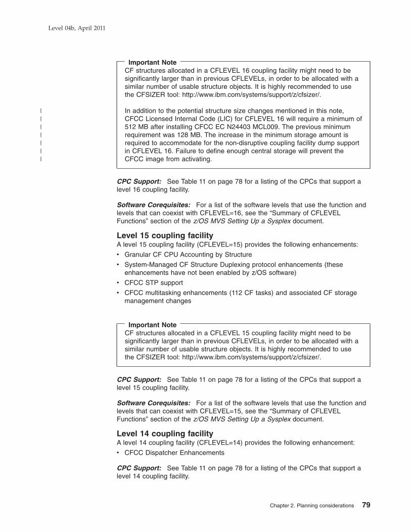
Important NoteCF structures allocated in a CFLEVEL 16 coupling facility might need to besignificantly larger than in previous CFLEVELs, in order to be allocated with asimilar number of usable structure objects. It is highly recommended to usethe CFSIZER tool: http://www.ibm.com/systems/support/z/cfsizer/.
In addition to the potential structure size changes mentioned in this note,CFCC Licensed Internal Code (LIC) for CFLEVEL 16 will require a minimum of512 MB after installing CFCC EC N24403 MCL009. The previous minimumrequirement was 128 MB. The increase in the minimum storage amount isrequired to accommodate for the non-disruptive coupling facility dump supportin CFLEVEL 16. Failure to define enough central storage will prevent theCFCC image from activating.
CPC Support: See Table 11 on page 78 for a listing of the CPCs that support alevel 16 coupling facility.
Software Corequisites: For a list of the software levels that use the function andlevels that can coexist with CFLEVEL=16, see the “Summary of CFLEVELFunctions” section of the z/OS MVS Setting Up a Sysplex document.
Level 15 coupling facilityA level 15 coupling facility (CFLEVEL=15) provides the following enhancements:
v Granular CF CPU Accounting by Structure
v System-Managed CF Structure Duplexing protocol enhancements (theseenhancements have not been enabled by z/OS software)
v CFCC STP support
v CFCC multitasking enhancements (112 CF tasks) and associated CF storagemanagement changes
Important NoteCF structures allocated in a CFLEVEL 15 coupling facility might need to besignificantly larger than in previous CFLEVELs, in order to be allocated with asimilar number of usable structure objects. It is highly recommended to usethe CFSIZER tool: http://www.ibm.com/systems/support/z/cfsizer/.
CPC Support: See Table 11 on page 78 for a listing of the CPCs that support alevel 15 coupling facility.
Software Corequisites: For a list of the software levels that use the function andlevels that can coexist with CFLEVEL=15, see the “Summary of CFLEVELFunctions” section of the z/OS MVS Setting Up a Sysplex document.
Level 14 coupling facilityA level 14 coupling facility (CFLEVEL=14) provides the following enhancement:
v CFCC Dispatcher Enhancements
CPC Support: See Table 11 on page 78 for a listing of the CPCs that support alevel 14 coupling facility.
Level 04b, April 2011
Chapter 2. Planning considerations 79
|||||||

Software Corequisites: For a list of the software levels that use the function andlevels that can coexist with CFLEVEL=14, see the “Summary of CFLEVELFunctions” section of the z/OS MVS Setting Up a Sysplex document.
Level 13 coupling facilityA level 13 coupling facility (CFLEVEL=13) provides the following enhancement:
v Performance enhancements for Castout
CPC Support: See Table 11 on page 78 for a listing of the CPCs that support alevel 13 coupling facility.
Software Corequisites: For a list of the software levels that use the function andlevels that can coexist with CFLEVEL=13, see the “Summary of CFLEVELFunctions” section of the z/OS MVS Setting Up a Sysplex document.
Level 12 coupling facility
Enhancements: A level 12 coupling facility (CFLEVEL=12) provides the followingenhancements:
v 64- bit CFCC support; removal of the 2 GB control store limit, and removal of thedistinction between control and non-control store
v 48 concurrent tasks
v Support for Message Timing Ordering providing enhanced scalability of parallelsysplex.
v System-Managed Coupling Facility (CF) Duplexing
v Cache structure architecture extensions for Batch Write, Castout, andCross-Invalidate functions
v Support for > 15 LPs
v Support for MCSS
CPC Support: See Table 11 on page 78 for a listing of the CPCs that support alevel 12 coupling facility.
Software Corequisites: For a list of the software levels that use the function andlevels that can coexist with CFLEVEL=12, see the “Summary of CFLEVELFunctions” section of the z/OS MVS Setting Up a Sysplex document.
Coupling Facility Resource Management (CFRM) policy considerationsTo define how to manage z/OS images and coupling facilities in the sysplex, youmust specify hardware configuration information in the coupling facility resourcemanagement (CFRM) policy as follows:
v Coupling facility node descriptor information
You must identify each coupling facility in the sysplex and the processor complexon which it is running. To do so, you must specify the following information in theCFRM policy:
CFRM parameter Description
PLANT Plant of manufacture
SEQUENCE Machine sequence number
SIDE Machine side
TYPE Machine type
MFG Manufacturer
Level 04b, April 2011
80 PR/SM Planning Guide

CPCID CPC identifier
This information is available on the CPC Details panel. You can access the CPCDetails panel by opening the CPC object that is running the coupling facility LP.
v LP information for the coupling facility
For a coupling facility residing on a System z10 model, the partition ID specifiedon the activation profile for the CF image on the Support Element or hardwaremaster console must match the number specified in the PARTITION keyword ofthe CF statement in the policy information defined in the CFRM policy. IBMrecommends that the LP names for the CF LPs in IOCP input files match thenames used in the NAME keyword in the CF statement in the CFRM policy.
You can find the LP names in either the IOCP or HCD reports.
Coupling facility channelsCoupling facility channels are System z10 channels that use fiber optic cables (CFPchannel paths), the self-timed interface (STI) cables of the channel subsystem (CBPchannel paths), an InfiniBand host channel adapter (HCA) (CIB channel paths), orinternal memory bus (ICP channel paths) to provide the connectivity for datasharing between a coupling facility and the central processor complexes (CPCs) orlogical partitions (LPs) directly attached to it.
The class of CHPIDs, known as peer mode channels, provide both sender andreceiver capability on the same link. Peer mode links come in these varieties:Internal Coupling channels (TYPE=ICP), Integrated Cluster Bus channels(TYPE=CBP), InfiniBand (TYPE=CIB), and ISC-3 links (TYPE=CFP). Each ICP,CBP, CIB, and CFP channel can be configured as an unshared channel path to asingle coupling facility or z/OS image, or as a shared channel path among severalz/OS images and one coupling facility image.
Note: The following bulleted items only describe z/OS to coupling facilityconnections. However, they also apply to coupling facility duplexingconnections (CF to CF).
Coupling facility channels:
v Require a point-to-point connection (direct channel attach between a CPC or LPand a coupling facility). Internal Coupling channels can only be used to connect acoupling facility and LPs on the same CPC.
v Can be used to connect a coupling facility to other LPs on the same CPC whena coupling facility is one of multiple LPs running on a single CPC. Internalcoupling channels are recommended for these connections.
v Can be redundantly configured (two or more coupling facility channels from eachCPC involved in coupling facility data sharing) to enhance availability and avoidextended recovery time. This does not apply to Internal Coupling channels.
v Require ICP, CBP, CIB, or CFP channel path definition at the coupling facility endof a coupling facility channel connection.
v Require ICP, CBP, CIB, or CFP channel path definition at the z/OS (and, forSystem-Managed CF Structure Duplexing, the coupling facility) end of a couplingfacility channel connection.
v Require a CBP, CFP, CIB, or ICP channel path be connected to a CBP, CFP,CIB, or ICP channel path, respectively. You must define the ICP channel paths inpairs and you must connect each pair. You connect an ICP channel path to anICP channel path by specifying the CPATH keyword on the CHPID statement forevery ICP channel path.
Level 04b, April 2011
Chapter 2. Planning considerations 81

Internal Coupling channelThe Internal Coupling channel emulates the coupling facility functions in LICbetween images within a single system. Internal Coupling channel implementation iscompletely logical, requiring no channel or even cable hardware. However, a CHPIDnumber must be defined in the IOCDS. Internal Coupling channels cannot be usedfor coupling connections to images in external systems.
Partitions with Internal Coupling channels can also have coupling facility channelswhich allow external system coupling. ICs, which use the system bus, are extremelyfast (approximately 6 GB/second).
Internal Coupling channels have channel path type ICP (Internal Coupling Peer).Internal Coupling channels are identified by 2 CHPIDs representing the two ends ofa coupling link. The rules that apply to the ICP CHPID type are the same as thosewhich apply to external coupling link types, with the exception that the followingfunctions are not supported:v Service On/Offv Reset I/O Interfacev Reset Error Thresholdsv Swap Channel Pathv CHPID Reassignv Channel Diagnostic Monitorv R/Vv Configuration Manager Vital Product Data (VPD)
Internal coupling channels have improved coupling performance over ICBs andcoupling facility channels.
Integrated cluster bus channelsIntegrated cluster bus channels (ICBs) are coupling facility channels that use theself-timed interface (STI) cables of the channel subsystem to provide theconnectivity for data sharing between a coupling facility and the CPCs or LPsdirectly attached to it. ICBs allow an integrated cluster bus channel to use most ofthe high bandwidth of the STI bus.
Additionally, the improved data rate made possible by the superior bandwidth of theintegrated cluster bus channel enhances performance by reducing the latency ofsynchronous send messages and CP idle time which results in improved workloadthroughput.
Integrated cluster bus channels:
v Require CBP channel path definition (coupling facility peer channel capability) atthe coupling facility end of a coupling facility channel connection. CBP channelpaths are defined for ICB-4 links.
v Require CBP channel path definition (coupling facility peer channel capability) atthe z/OS (and, for System-Managed CF Structure Duplexing, the coupling facility)end of a coupling facility channel connection. CBP channel paths are defined forICB-4 links.
v Each CBP channel path must be connected to another CBP channel path. ICB-4links are defined as CBP channel paths. However, it is further required that anICB-4 link be connected to another ICB-4 link.
Summary of CPC Support for Integrated Cluster Bus Channels: Integratedcluster bus channels are optional on System z10 models.
Level 04b, April 2011
82 PR/SM Planning Guide

Note: ICB-4 links are not supported on System z10 Model E64.
ISC-3 LinksISC-3 links (TYPE=CFP channel paths) process coupling facility requests.
InfiniBand host channel adapter (HCA)An InfiniBand host channel adapter (HCA) can be used for a coupling link betweena z/OS image and a coupling facility (CF) image. The IOP wraps the couplingmessages in an InfiniBand packet and uses industry-standard InfiniBand linkarchitecture to send the message. The IOP at the other end unwraps the couplingmessage and delivers it to the intended receiver.
InifiniBand coupling links for Parallel SysplexInfiniBand coupling link technology provides increased bandwidth at greater cabledistances than ICB-4. The IBM System z10 supports a 12x (12 lanes of fibre ineach direction) InfiniBand-Double Data Rate (IB-DDR) coupling link which isdesigned to support a total interface link data rate of 6 Gigabytes per second(GBps) in each direction. The maximum distance for this point-to-point link overfibre optic cabling is 150 meters (492 feet). This InfiniBand coupling link providesimproved performance over the current ISC-3 coupling link in data centers wheresystems are less than 150 m apart.
A 12x InfiniBand-Single Data Rate (IB-SDR) coupling link is available on all Systemz9 EC and System z9 BC servers. This coupling link is designed to support a totalinterface link data rate of 3 Gigabytes per second (GBps) in each direction. ThisInfiniBand coupling link provides improved performance over the current ISC-3coupling link in data centers where systems are less than 150 m apart. These 12xIB-SDR coupling links cannot be used for coupling link connectivity between two z9servers. When a System z10 server is connected to a System z9 server usingpoint-to-point InfiniBand cabling, the link auto-negotiates to the highest commondata rate of 3 GBps.
InifiniBand coupling links also provide the ability to define up to 16 CHPIDs on asingle HCA adapter, allowing physical coupling links to be shared by multiplesysplexes. This also provides additional subchannels for Coupling Facilitycommunication, improving scalability, and reducing contention in heavily usedsystem configurations. It also allows for one CHPID to be directed to one CF, andanother CHPID directed to another CF on the same target server, using the samephysical link. For detailed information about InfiniBand coupling links, see GettingStarted with InfiniBand on System z10 and System z9, SG24–7539, available fromthe Redbooks® website: http://www.redbooks.ibm.com/.
InfiniBand coupling links:
v Require CIB channel path definition (coupling facility peer channel capability) atthe coupling facility end of a coupling facility channel connection. CIB channelpaths are defined for IFB links.
v Require CIB channel path definition (coupling facility peer channel capability) atthe z/OS (and, for System-Managed CF Structure Duplexing, the coupling facility)end of a coupling facility channel connection. CIB channel paths are defined forIFB links.
v Each CIB channel path must be connected to another CIB channel path. IFBlinks are defined as CIB channel paths. However, it is further required that an IFBlink be connected to another IFB link.
Level 04b, April 2011
Chapter 2. Planning considerations 83

v When defining CIB CHPIDs, you must specify both the name of the system(CSYSTEM keyword) this CHPID connects to and the CSS and MIFID (CPATHkeyword) on that system that this CHPID connects to.
InfiniBand Long Reach: InfiniBand can be used for Parallel Sysplex coupling andSTP communication at unrepeated distances up to 10 km (6.2 mi) and greaterdistances when attached to qualified optical networking solutions. InfiniBandcoupling links supporting extended distance are referred to as Long Reach 1x (onepair of fiber) InfiniBand.
v Long Reach 1x InfiniBand coupling links support single data rate (SDR) at 2.5gigabits per second (Gbps) when connected to a DWDM capable of SDR (1xIB-SDR).
v Long Reach 1x InfiniBand coupling links support double data rate (DDR) at 5Gbps when connected to a DWDM capable of DDR (1x IB-DDR).
The link data rate auto-negotiates from SDR to DDR depending upon the capabilityof the attached equipment.
Long reach 1x InfiniBand coupling links use the Host Channel Adapter2 OpticalLong Reach fanout card. Like the 12x InfiniBand coupling link feature, the HCA2-OLR fanout card can also be used to exchange timekeeping messages for ServerTime Protocol (STP).
This environment supports use of 9 micron single mode fiber optic cables with LCDuplex connectors, the same fiber optic cable used with InterSystem Channel-3(ISC-3).
The Channel Path Identifier remains CHPID type CIB whether 12x IB-SDR or DDRor 1x IB-SDR or DDR.
Long reach 1x InfiniBand coupling links (1x IB-SDR or 1x IB-DDR) are analternative to ISC-3 and offer greater distances with support for point-to-pointunrepeated distances up to 10 km (6.2 mi) using 9 micron single mode fiber opticcables. Greater distances can be supported with System z-qualified opticalnetworking solutions. Long Reach 1x InfiniBand coupling links support the samesharing capabilities as the 12x InfiniBand version, allowing one physical link to beshared by multiple operating system images or Coupling Facility images on a singlesystem. They also provide the capability to have more than 1 CHPID associatedwith the physical IB Coupling link.
Note: The InfiniBand link data rates do not represent the performance of the link.The actual performance is dependent upon many factors including latencythrough the adapters, cable lengths, and the type of workload. Specifically,with 12x InfiniBand coupling links, while the link data rate is higher than thatof ICB, the service times of coupling operations are greater, and the actualthroughput is less.
Coupling facility channels (TYPE=CFP, TYPE=CBP, TYPE=CIB, orTYPE=ICP)You can configure a CFP, CBP, CIB, or ICP channel path as:
v An unshared dedicated channel path to a single LP
v An unshared reconfigurable channel path that can be configured to only one LPat a time but which can be dynamically moved to another LP by channel pathreconfiguration commands
Level 04b, April 2011
84 PR/SM Planning Guide

v A shared channel path that can be shared between at most one coupling facilityimage and one or more z/OS images.
Shared coupling facility channel path recommendations: IBM recommends thefollowing:
1. For shared coupling facility channel paths, make sure that only LPs that need touse the channel path have it configured online. Doing so eliminatesunnecessary traffic on the channel path from those systems that have it onlinebut do not have the attached coupling facility in the active CFRM policy.
2. These channel paths can result in ’Path Busy’ conditions when another LP isusing the path. This situation can result in delays in getting requests to thecoupling facility on this path. The number of ’Path Busy’ conditions can be foundin the RMF CF Subchannel Activity report in the BUSY COUNTS columnlabeled PTH. As a guideline, if this count exceeds 10% of the total requests,you should consider not sharing the channel path or adding additional couplingfacility channel paths.
Defining internal coupling channels (TYPE=ICP)Internal coupling channels are virtual attachments and, as such, require no realhardware. However, they do require CHPID numbers and they do need to bedefined in the IOCDS.
It is suggested that you define a minimum of internal coupling channels. For mostcustomers, IBM suggests defining just one pair of ICP channel paths for eachcoupling facility logical partition (LP) in your configuration. For instance, if yourgeneral-purpose configuration has several ESA LPs and one CF LP, you woulddefine one pair of connected ICP CHPIDs shared by all the LPs in yourconfiguration. If your configuration has several ESA LPs and two CF LPs, you stillwould only define one connected pair of ICP CHPIDs, but one ICP CHPID shouldbe defined as shared by the ESA LPs and one CF LP while the other ICP CHPID isdefined as shared by the ESA LPs and the other CF LP. Both of these examplesbest use the peer capabilities of these coupling channels by using the sending andreceiving buffers of both channels.
You must define ICP CHPIDs in pairs, and you must connect each pair. Aconnected pair of ICP CHPIDs is called an internal coupling link. Both ends of theinternal coupling link must be specified by defining which ICPs are to communicatewith each other. Use the CPATH keywords in the CHPID statement to connectinternal coupling CHPIDs (see page 57).
Maximum recommended number of ICP CHPIDs: Real CPU resources are usedto implement the link function of connected ICP CHPIDs. Production environmentsshould limit the maximum number of internal coupling links that are defined for aCPC to optimize the internal coupling link function utilization of CPU resources. Thismaximum number of internal coupling links is based on the number of availablephysical CPs on the CPC. This maximum number of internal coupling links can becalculated by taking the number of CPs in the CPC that are used forgeneral-purpose CPs and for ICF CPs, and subtracting one from that total. Forexample: a CPC that consists of four general-purpose CPs and two ICF CPs wouldhave a maximum five [(4 + 2 = 6) - 1 = 5] internal coupling links recommended.This represents a maximum total of 10 ICP CHPIDs being defined.
I/O configuration considerationsICP IOCP supports coupling facility channel path definition on the System z10 CPC.
Level 04b, April 2011
Chapter 2. Planning considerations 85

With z/OS, HCD provides controls for defining coupling facility channels. HCD alsoautomatically generates the control unit and device definitions associated with CFP,CBP, CIB, or ICP channel paths.
IBM recommends that you use the Hardware Configuration Definition (HCD), whenpossible, to define the coupling facility channel configuration to the channelsubsystem.
Considerations when migrating from ICMF to ICsOn previous CPCs, PR/SM LPAR provided an Integrated Coupling Migration Facility(ICMF) which is not supported on System z10.
v Use HCD to:
– Define one shared ICP CHPID that is available for all the ESA logicalpartitions that were communicating with the first or only coupling facility logicalpartition using ICMF.
- If there is a second coupling facility using ICMF being migrated, make thisICP CHPID available to the second coupling facility logical partition as well.
- If there is not a second coupling facility, make this ICP CHPID available tothe first or only coupling facility as well.
– Define a second shared ICP CHPID that is available for the first or onlycoupling facility partition using ICMF.
- If there is a second coupling facility using ICMF that is being migrated,make this second ICP CHPID available to all the ESA logical partitions thatwere communicating with the second coupling facility logical partition usingICMF as well.
- If there is not a second coupling facility, make this second ICP CHPIDavailable to all the ESA logical partitions that were communicating with thefirst or only coupling facility logical partition using ICMF as well. For moreinformation, please see “Defining internal coupling channels (TYPE=ICP)”on page 85.)
– Connect the two ICP CHPIDs together.
For the case previously stated, where there is only one coupling facility logicalpartition using ICMF being migrated, the result is that both ICP CHPIDs are sharedby all the ESA logical partitions and also the coupling facility logical partition thatthey are to communicate with. This is the correct configuration for a peer couplinglink connected within the same CPC.
Linux operating system planning considerationsLinux is an open operating system with a wealth of applications which, in mostcases, can run on a System z10 with a simple recompile. The System z10 includesfeatures that provide an extremely cost-effective environment in which to run Linux.
Integrated Facility for Linux (IFL)On System z10 models, you can purchase and install one or more IFL featuresexclusively for Linux and OpenSolaris workloads (a single Linux image, or z/VMVersion 5.3 and later with only Linux and OpenSolaris guests) with no effect on theSystem z10 model designation. Consequently, no additional IBM operating systemor middleware charges are incurred with the addition of this capacity unless thatsoftware is actually running in that additional capacity.
Level 04b, April 2011
86 PR/SM Planning Guide

These features are ordered separately, and are distinguished at the hardware levelfrom any general-purpose CPs, ICFs, zAAPs, or zIIPs. CPs, ICFs, IFLs, zAAPs,and zIIPs are perceived by the system as multiple resource pools.
With this feature, Linux, or z/VM Version 5.3 and later with only Linux andOpenSolaris guests, runs on IFLs. These IFLs cannot be used to run other IBMoperating systems such as z/OS, z/VSE, or TPF. Only logical partitions specified aseither Linux-Only Mode or z/VM Mode in their Activation profiles can be allocatedIFLs. IFLs can be allocated as either dedicated or shared. z/VM 5.3 and later canrun in a logical partition that includes IFLs and can dispatch Linux and OpenSolarisguest virtual IFLs on the real IFLs. z/VM 5.3 and later can also simulate IFLs forLinux and OpenSolaris guests, dispatching virtual IFLs on real general-purposeprocessors (CPs).
z/VM-mode allows z/VM users to configure all CPU types on a z10 logical partition.z/VM 5.4 and later versions support this mode, which provides increased flexibilityand simplifies systems management, by allowing z/VM to manage guests toperform the following tasks all in the same VM LPAR:
v Operate Linux on System z on IFLs
v Operate z/VSE and z/OS on CPs
v Offload z/OS system software overhead, such as DB2 workloads, on zIIPs
v Provide an economical Java execution environment under z/OS on zAAPs
z/VM utilizing IFL featuresz/VM utilizing IFL features provides an easy-to-use high-performance hypervisorthat operates within a logical partition. It can create a significant number of Linuxand OpenSolaris images. z/VM creates and manages Linux and OpenSolarisimages quickly and easily, providing the ability to share resources, and supports anarbitrary number of internal networks that can be used for high-speedcommunication among Linux images.
IBM System z10 Application Assist Processor (zAAP)The IBM System z10 Application Assist Processor (zAAP) is available on theSystem z10. This specialized processing unit provides an economical Javaexecution environment for customers who want the traditional Qualities of Serviceand the integration advantages of the System z10 platform.
When configured with general-purpose processors within logical partitions runningz/OS, zAAPs might help increase general-purpose processor productivity and mightcontribute to lowering the overall cost of computing for z/OS Java technology-basedapplications. zAAPs are designed to operate asynchronously with the generalprocessors to execute Java programming under control of the IBM Java VirtualMachine (JVM). This can help reduce the demands and capacity requirements ongeneral-purpose processors which might then be available for reallocation to otherSystem z10 workloads.
The IBM JVM processing cycles can be executed on the configured zAAPs with noanticipated modifications to the Java application(s). Execution of the JVMprocessing cycles on the zAAP is a function of the Software Developers Kit (SDK)1.4.1 for zSeries, z/OS, and PR/SM.
Level 04b, April 2011
Chapter 2. Planning considerations 87

The amount of general-purpose processor savings varies based on the amount ofJava application code executed by zAAP(s). This is dependent upon the amount ofJava cycles used by the relevant application(s) and on the zAAP execution modeselected by the customer.
Execution of the Java applications on zAAPs, within the same z/OS logical partitionas their associated database subsystems, can also help simplify the serverinfrastructure and improve operational efficiencies. For example, use of zAAPscould reduce the number of TCP/IP programming stacks, firewalls, and physicalinterconnections (and their associated processing) that might otherwise be requiredwhen the application servers and their database servers are deployed on separatephysical server platforms.
IBM does not impose software charges on zAAP capacity. Additional IBM softwarecharges apply when additional general-purpose CP capacity is used.
Customers are encouraged to contact their specific ISVs/USVs directly to determineif their charges are affected.
On System z10 models, you can purchase and install one or more zAAP featureswith no effect on the model designation. Consequently, no additional IBM operatingsystem or middleware charges are incurred with the addition of this capacity unlessthat software is actually running in that additional capacity. zAAP features areordered separately and are distinguished at the hardware level from anygeneral-purpose Central Processors (CPs), Internal Coupling Facility (ICF)processors, Integrated Features for Linux (IFLs), and System z10 IntegratedInformation Processor (zIIPs).
z/VM 5.3 and later can run in a logical partition that includes zAAPs and candispatch z/OS guest virtual zAAPs on the real zAAPs. z/VM 5.3 and later can alsosimulate zAAPs for z/OS guests, dispatching virtual zAAPs on real general-purposeprocessors (CPs).
IBM System z10 Integrated Information Processor (zIIP)The IBM System z10 Integrated Information Processor, or IBM zIIP, is the latestcustomer-inspired specialty engine for System z10. It provides a cost-effectiveworkload reduction environment that is used by DB2 and other software products,some from ISVs. The zIIP is designed to help improve resource optimization andlower the cost of eligible workloads, enhancing the role of the mainframe as thedata hub of the enterprise.
The execution environment of the IBM zIIP accepts eligible work from z/OS 1.7(with a required Web Deliverable function installed to support it), or z/OS 1.8 orhigher, which manages and directs the work between the general-purposeprocessor and the zIIP. DB2 for z/OS V8 uses the zIIP capability for eligibleworkloads. IBM zIIPs are designed to free up general-purpose capacity which mightbe used by other workloads.
In addition to improving the utilization of existing System z10 resources, the zIIPmight help you to use the z/OS and DB2 for z/OS qualities of service for dataaccess and information management across your enterprise. It does this by makingdirect access to DB2 more cost effective and potentially reducing the need for manylocal copies of the data and the complexity that brings.
Level 04b, April 2011
88 PR/SM Planning Guide

On System z10 models, you can purchase and install one or more zIIP featureswith no effect on the model designation. Consequently, no additional IBM operatingsystem or middleware charges are incurred with the addition of this capacity unlessthat software is actually running in that additional capacity. zIIP features are orderedseparately and are distinguished at the hardware level from any general-purposeCentral Processors (CPs), Internal Coupling Facility (ICF) processors, IntegratedFeatures for Linux (IFLs), and zAAPs.
z/VM 5.3 and later can run in a logical partition that includes zIIPs and can dispatchz/OS guest virtual zIIPs on the real zIIPs. z/VM 5.3 and later can also simulatezIIPs for z/OS guests, dispatching virtual zIIPs on real general-purpose processors(CPs).
Concurrent patchConcurrent patch is available on all System z10 models. It is possible to apply BPC,UPC, Support Element (SE), Hardware Management Console, channel LicensedInternal Code (LIC), LPAR, coupling facility control code, I390, and PU patchesnondisruptively and concurrent with system operation. There can still be situationswhere a small percentage of patches is disruptive; however, with all System z10models, all major LIC components now support concurrent patch.
Additionally, there is also support for multiple EC streams (one per major LICcomponent) further minimizing the number of disruptive patch sessions. Onprevious models, a single EC stream contained all major LIC components andprovided a mandatory sequence for patch application. This could lead to situationswhere a disruptive patch belonging to one LIC component, for example, PU, couldprevent you from applying all nondisruptive SE patches if one or more of the SEpatches came after this channel patch in the patch application sequence.
Patches for each major LIC component have their own sequence for patchapplication. This means that disruptive patches belonging to one LIC component nolonger stand as an obstacle to the concurrent application of nondisruptive patchesbelonging to another LIC component as long as the patches in question are nototherwise defined as corequisite for each other.
CFCC enhanced patch applyThe CFCC patch apply process is enhanced to eliminate the need for a Power OnReset (POR) of the System z10 to apply a disruptive CFCC patch. CFCC enhancedpatch apply provides you the ability to:
v Selectively apply the new patch to one of possibly several CFs running on aSystem z10. For example, if you have a CF that supports a test parallel sysplexand a CF that supports a production parallel sysplex on the same System z10,you can apply a disruptive patch to only the test CF without affecting theproduction CF. After you have completed testing of the patch, it can be applied tothe production CF as identified in the example.
v Allow all other logical partitions on the System z10 where a disruptive CFCCpatch will be applied to continue to run without being impacted by the applicationof the disruptive CFCC patch.
The enhanced patch apply does not change the characteristics of a concurrentCFCC patch, but does significantly enhance the availability characteristics of adisruptive CFCC patch by making it much less disruptive.
Level 04b, April 2011
Chapter 2. Planning considerations 89

Note: Any POR of the servers results in the disruptive patch being applied to CFpartitions.
Dynamic capacity upgrade on demandSystem z10 includes a function to dynamically increase the number of CPs, ICFs,IFLs, zAAPs, or zIIPs without an intervening IPL. A logical partition (LP) might bedefined with both an initial and reserved amount of logical CPs. This enables adefinition where the number of logical CPs for a logical partition is greater than thenumber of physical CPs installed on the model. These reserved CPs areautomatically in a deconfigured state at partition activation and can be broughtonline at any future time by the SCP operator command if the requested resource isavailable. To prepare for a nondisruptive upgrade, a Logical Partition simply needsto be defined and activated in advance with an activation profile indicating reservedCPs. This helps ensure that any planned logical partition can be as large as thepossible physical machine configuration, nondisruptively.
With enhanced support available on z10, the logical CP definition for a logicalpartition can be dynamically changed without requiring a reactivation of the logicalpartition. This allows you to add to the definition of offline CPs (or any othersupported processor types) dynamically should the need arise. If the system controlprogram running in that logical partition supports this dynamic add capability, theadditional offline CPs can be configured online in the same way as preplannedreserved CPs are brought online.
For more information about using dynamic CPU addition, see z/OS MVS Planning:Operations.
The following example assumes a nondisruptive concurrent CP upgrade from an8-Way to a 9-Way Server.
PR/SM shared partitionsPR/SM configurations supporting multiple partitions, all sharing CPs, supportconcurrent CP upgrades. PR/SM code, once signaled that one or more centralprocessors have been made available to the configuration, will vary them onlineautomatically into the “shared pool” of physical CPs and begin full utilization of theadded capacity. In the following example, three partitions sharing eight physical CPsare able to share the increased capacity resulting from a nondisruptive upgrade to a9- way server without any other configuration changes. In the second upgradescenario, Partition 1 is additionally changed from a 4-way to a 5-way partitionnondisruptively. The preparation for this is straightforward and easy. Simply defineand activate logical Partition 1 with four initial and one reserved logical CPs (seeFigure 37 on page 159 for a similar example). At the time of the concurrent CPupgrade, the SCP operator command can be used in Partition 1 to configure a fifthCP online to the shared partition without interruption to any logical partition.
Level 04b, April 2011
90 PR/SM Planning Guide

Mixed shared and dedicated PR/SM partitionsAs with configurations in which all PR/SM partitions share available CPs, thoseshared partitions within a mixed configuration also support concurrent CP upgrade.CPs are added, without disruption to any of the partitions, to the pool of physicalCPs shared among the shared CP LPs. In addition, partitions configured withdedicated CPs in a mixed environment can add new CP capacity while both theshared CP partitions and the dedicated CP partition run uninterrupted. To preparefor this ability, in the following example simply define Partition 3 as a three-waydedicated partition with two initial logical CPs and one reserved logical CP (seeFigure 37 on page 159 for a similar example). The reserved logical CP is offlineautomatically at the time of partition activation. At the time of the concurrent CPupgrade, the SCP operator command can be used in the dedicated partition toconfigure a third CP online to the dedicated partition without interruption to anylogical partition.
Level 04b, April 2011
Chapter 2. Planning considerations 91

Multiple dedicated PR/SM partitionsConfigurations in which all PR/SM partitions use dedicated CPs, where there ismore than one dedicated partition, also support concurrent CP upgrade. CPs areadded to the configuration, without disruption to any of the partitions, and can bebrought online to a dedicated partition without an interruption. In the followingexample, all ICFs in the configuration are dedicated. The partition (ICF 1) is definedfor the ability to be upgraded dynamically. To prepare for this ability, simply defineICF 1 as a two-way dedicated partition with one initial and one reserved logical CP(see Figure 37 on page 159 for a similar example). At the time of the concurrent CPupgrade, the CF operator command can be used in the ICF 1 dedicated partition toconfigure a second ICF CP online to the dedicated partition without interruption toany logical partition. Note the same type of procedure can be accomplished withlogical partitions using dedicated general-purpose CPs.
Shared Internal Coupling FacilityConcurrent upgrade can be used to add a PU to a shared pool of PUs supportingexisting Internal Coupling Facilities. In the following example, Partition 1 is definedfor the ability to be upgraded dynamically. To prepare for this ability, simply definePartition 1 as a seven-way shared partition with six initial and one reserved logicalCPs (see Figure 37 on page 159 for a similar example). At the time of theconcurrent CP upgrade, the CF operator command can be used in Partition oneshared partition to configure a seventh ICF CP online to the shared partition withoutinterruption to any logical partition. Partition 2 in this case could have also beendefined as a seven-way shared ICF partition with one ICF configured offline. Thiswould allow Partition 2 to grow concurrently without an outage as well.
Level 04b, April 2011
92 PR/SM Planning Guide

Dynamic capacity upgrade on demand limitations1. Valid upgrade towers are as follows starting at the smallest model in the
pathway:
z10 BC ModelsE10
z10 EC ModelsE12, E26, E40, E56, E64
Inactive (spare) PUs can be added concurrently, dynamically providingnondisruptive upgrade of processing capability. They can be characterized, inany combination, as CPs, ICFs, IFLs, zAAPs, or zIIPs. The number of zAAPs orzIIPs can exceed the number of CPs.
2. For shared CP PR/SM configurations, added CPs are brought into the pool ofshared CPs, effectively increasing the number of physical CPs to be sharedamong partitions. To increase the number of logical CPs online to an LP, simplydefine the LP with both initial and reserved logical CPs. Then all you need to dois configure on the extra logical CP(s) after the concurrent upgrade.
3. All models can define logical partitions with as many reserved CPs asnecessary. With thoughtful planning, there is never a need for a disruptiveincrease in the number of logical CPs
4. The maximum initially online logical CP width that logical partitions can bedefined and activated with at any point in time is as follows (the maximumdefined logical CP width is as great as the total number of CPs achievable withconcurrent CPU upgrade):
v Maximum initial logical CPs defined for a dedicated partition equals physicalCPs online for the current model minus physical CPs currently dedicated andonline to other dedicated partitions minus the maximum online number ofshared CPs among all the activated logical partitions that are using sharedCPs.
v Maximum initially online logical CPs defined for a shared partition equalsphysical CPs online for the current model minus physical CPs currentlydedicated and online to other partitions using dedicated CPs.
v Maximum total logical CPs (including initial and reserved) for any partitionequals the number of physical CPs achievable through concurrent CPupgrade.
v When a logical partition is defined to use ICFs, IFLs, zIIPs or zAAPs, theserules are applied against the installed processors of that type. In the case ofzAAPs and zIIPs, logical partitions can have a combination ofgeneral-purpose processors and zAAPs/zIIPs defined. These rules apply toeach processor type defined to the partition independently. The total numberof all logical processors defined to the logical partition cannot exceed themaximum supported for a logical partition by the CEC, independent ofprocessor type.
Level 04b, April 2011
Chapter 2. Planning considerations 93

Concurrent Memory UpgradeThe System z10 includes a function to dynamically increase the amount ofconfigured storage. Concurrent Memory Upgrade allows for a memory upgradewithout changing hardware or experiencing an outage, provided there is enoughspare memory existing on the memory cards. An IML is not required to use thepreviously unavailable storage. It is immediately available for allocation to logicalpartitions as either central or expanded storage. The new storage can be allocatedto either newly activated logical partitions or to already active logical partitions byusing dynamic storage reconfiguration (see “Dynamic storage reconfiguration” onpage 110). In planning for a concurrent memory upgrade, logical partition activationprofiles should be defined with storage (central and/or expanded) specifications thatinclude a reserved as well as an initial storage amount. Following the completion ofthe concurrent memory upgrade operation, issue the z/OS command CFSTOR(E=1),ONLINE or the z/OS command CF ESTOR(E=1),ONLINE to bring thenew memory online to already active LPs for which a reserved central storageamount, or a reserved expanded storage amount (respectively) was specified.
Capacity Backup Upgrade (CBU) capabilityThis orderable feature, available on z10 Models, can be integrated withGeographically Dispersed Parallel Sysplex™. This should reduce disaster recoverytimes by automating the Capacity Backup Upgrade process at a remote site.
Operationally, the planning considerations and limitations for Capacity BackupUpgrade, for mode purposes, are similar to those for Dynamic Capacity Upgrade onDemand. Planning is simple because reserved logical CPs can be specified forlogical partitions on the backup system. The logical CPs can then be broughtonline, quickly and nondisruptively.
Concurrent Undo CBU is provided to dynamically remove from the configurationprocessors that had been added with Capacity Backup Upgrade. The server fordisaster recovery with Capacity Backup Upgrade activated can now be restored toits base configuration without requiring a system outage.
When a disaster occurs, Capacity Backup Upgrade is intended to provide the extracapacity without disruption. When the disaster is over and normalcy is restored,Concurrent Undo CBU is intended to allow the system to be returned to its previousconfiguration without disruption.
Annual testing of a Capacity Backup Upgrade system is highly recommended.Invoking the Capacity Backup Upgrade configuration is nondisruptive and nowreturns to the original configuration, after the test, without disruption as well.
When a typical Capacity Backup Upgrade occurs, typically logical processors areconfigured online so that the system closely resembles the failing system. Toprepare for Concurrent Undo CBU, the most expedient method is to simplyconfigure offline all those logical processors that were configured online in supportof the failing system.
In order for Concurrent Undo CBU to proceed, the restored original configurationmust have a physical processor for each online dedicated logical processor.Theoretically, the only additional requirement is that at least one nondedicatedphysical processor remains that matches each type (general purpose, ICF, IFL,zAAP, or zIIP) of online shared logical processors. However, it is highlyrecommended that shared logical processors be configured offline so that the
Level 04b, April 2011
94 PR/SM Planning Guide

highest number of online shared logical CPs for any active LP does not exceed thenumber of nondedicated physical CPs remaining. For further guidelines, see therules governing the number of CPs that can be specified for an activating logicalpartition on page 120.
Enhanced Book AvailabilityThe z10 is designed to allow a single book, in a multi-book server, to beconcurrently removed from the server and reinstalled during an upgrade or repairaction, while continuing to provide connectivity to the server I/O resources using asecond path from a different book. To help minimize the impact on currentworkloads and applications, you should ensure that you have sufficient inactivephysical resources on the remaining books to complete a book removal.
Enhanced book availability might also provide benefits should you choose not toconfigure for maximum availability. In these cases, you should have sufficientinactive resources on the remaining books to contain critical workloads whilecompleting a book replacement. Contact your IBM representative to help youdetermine the appropriate configuration. With proper planning, you might be able toavoid planned outages when using enhanced book availability.
Enhanced driver maintenance is another step in reducing the duration of a plannedoutage. One of the greatest contributors to downtime during planned outages isLicensed Internal Code (LIC) updates performed in support of new features andfunctions. When properly configured, the z10 is designed to support activatingselect new LIC level concurrently. Concurrent activation of the select new LIC levelis only supported at specific sync points (points in the maintenance process whenLIC might be applied concurrently - MCL service level). Sync points might existthroughout the life of the current LIC level. Once a sync point has passed, you willbe required to wait until the next sync point supporting concurrent activation of anew LIC level. Certain LIC updates are not supported by this function.
Preparing for Enhanced Book AvailabilityThis option determines the readiness of the system for the targeted book. Theconfigured processors and the in-use memory are evaluated for evacuation from thetargeted book to the unused resources available on the remaining books within thesystem configuration. In addition, the I/O connections associated with the targetedbook are analyzed for any Single Path I/O connectivity.
There are three states which can result from the prepare option:
v The system is ready to perform the Enhanced Book Availability for the targetedbook with the original configuration.
v The system is not ready to perform the Enhanced Book Availability due toconditions noted from the prepare step. See “Getting the system ready toperform Enhanced Book Availability” for more details.
v The system is ready to perform the Enhanced Book Availability for the targetedbook. However, processors were reassigned from the original configuration inorder to continue. “Reassigning non-dedicated processors” on page 97 fordetails.
Getting the system ready to perform Enhanced Book AvailabilityReview the conditions that are preventing the Enhanced book Availability optionfrom being performed. There are tabs on the resulting panel for Processors,Memory, and for various Single Path I/O conditions. Only the tabs that haveconditions preventing the perform option from being executed are displayed. Each
Level 04b, April 2011
Chapter 2. Planning considerations 95

tab indicates what the specific conditions are and possible options to correct theconditions. Following is an example panel:
In the example shown in Figure 23, the Processor tab displays, indicating thecorrective actions suggested for the processor configuration. Following is a list oftabs that might appear for your particular configuration:
ProcessorsUse this tab to view the corrective actions required for the processorconfiguration conditions that are preventing the Perform Enhanced BookAvailability option from being performed for the targeted book. You mightneed to deactivate partitions or deconfigure processors to meetrequirements as indicated by the panel data.
MemoryUse this tab to view the corrective actions required for the memoryconfiguration conditions that are preventing the Perform Enhanced BookAvailability option from being performed for the targeted book. You mayneed to deactivate partitions to meet requirements as indicated by the paneldata. The In-Use memory must be less than or equal to the availablememory on the remaining books within the system.
Single Path I/OUse this tab to view the corrective actions required for the single I/Oconfiguration conditions that are preventing the Perform Enhanced BookAvailability option from being performed for the targeted book. You need todeconfigure all the PCHIDs that are indicated by the panel data.
Single DomainUse this tab to view the corrective actions required for the single I/Odomain configuration conditions that are preventing the Perform EnhancedBook Availability option from being performed for the targeted book. Youneed to change the alternate path to a different book or deconfigure thePCHID.
Figure 23. Example of a prepare for enhanced book availability results window
Level 04b, April 2011
96 PR/SM Planning Guide

Single Alternate PathUse this tab to view the corrective actions required for the single I/Oconfiguration conditions that are preventing the Perform Enhanced BookAvailability option from being performed for the targeted book. You need tocorrect the alternate path error condition or deconfigure the PCHIDs.
Reassigning non-dedicated processorsFollowing is an example showing the Reassign Non-Dedicated Processors panel.Use this panel to change or accept the system processor assignments that aregenerated during the processing of the Prepare for Enhanced Book Availabilityoption. The processor values that are entered from this panel will be the processorconfiguration used during the Perform Enhanced Book Availability processing.
ATTENTIONThe values should never be altered without approval from the systemprogrammer.
Customer Initiated Upgrade (CIU)This feature is designed to allow timely response to sudden increased capacityrequirements by downloading and automatically applying a processor and/ormemory upgrade with the Web, using IBM Resource Link and the Remote SupportFacility.
Operationally, the planning considerations and limitations for CIU are like those forDynamic Capacity Upgrade on Demand and Concurrent Memory Upgrade. Planningis simple because reserved logical CPs can be specified for logical partition (LP)s inthe original configuration. The logical CPs can then be brought online, quickly andnondisruptively at the completion of the Concurrent Upgrade. Similarly, a reservedcentral and/or expanded storage amount can be specified for participating LPs andbrought online non-disruptively following the completion of the concurrent memoryupgrade.
Figure 24. Reassign non-dedicated processors window
Level 04b, April 2011
Chapter 2. Planning considerations 97

Concurrent Processor Unit conversionThe System z10 supports concurrent conversion of different Processor Unit (PU)types. This capability is extended to Central Processor (CPs), Integrated Facility forLinux (IFLs), zAAPs, zIIPs, and Internal Coupling Facility (ICFs) providing flexibilityin configuring a System z10 to meet the changing business environments.
For example, a Z10 EC Model E12 configured with eight CPs and two zAAPs couldbe reconfigured to eight CPs, one zAAP and one zIIP by ordering the appropriatePU conversion. This order generates a new LIC CC which can be installedconcurrently in two steps. First, one zAAP is removed from the configuration.Second, the newly available PU is activated as a zIIP.
Planning for nondisruptive install of crypto featuresCrypto Express2 and Crypto Express3 features can be added to logical partitionsnondisruptively using the Change LPAR Cryptographic Controls task. For moreinformation, see “Changing LPAR cryptographic controls” on page 200. Logicalpartitions can either be configured in advance or dynamically with the appropriatedomain indexes and Cryptographic numbers (see the Cryptographic Candidate Listinformation under “Parameter descriptions” on page 173).
If the customer plans to use ICSF or the optional cryptographic hardware, the CPCrypto Assist functions (CPACF DES/TDES) must be enabled. Many IBM productstake advantage of the cryptographic hardware using ICSF, so enabling CPACF isrecommended. View the CPC Details panel to determine if the CPACF feature isinstalled. For more detailed information, see the System z10 Support ElementOperations Guide and the z/OS Cryptographic Services ICSF TKE PCIXWorkstation User’s Guide. It is important to remember that when nondisruptivelyinstalling cryptos, the default configuration of the card is coprocessor (CEX2C orCEX3C). To change the configuration of a crypto, use the CryptographicConfiguration Panel. Once the crypto has been installed, and the previouspreparations made, the crypto is available to any partition that specifies theirassigned Cryptographic numbers in the Candidate List of the Image ActivationProfile. To bring the Cryptographic numbers online, perform a Config On of theCrypto (nondisruptive).
The Cryptographic Online List needs to be set up in the Image Activation Profile toreflect the crypto that you want to bring online automatically during the partitionactivation. If the Cryptographic Candidate List does not reflect the crypto that youplan to use, then these cryptos are not available to the logical partition after thispartition is activated. If the Cryptographic Online List is set up properly, the crypto isbrought online when the partition is activated and available to the operating systemwhen ICSF is started. Otherwise, a Configure On is necessary to bring the cryptoonline in the logical partition.
Level 04b, April 2011
98 PR/SM Planning Guide

Chapter 3. Determining the characteristics of logical partitions
Planning overview . . . . . . . . . . . . . . . . . . . . . . . 102Performance considerations. . . . . . . . . . . . . . . . . . . 102
Dedicated and shared central processors (CPs) . . . . . . . . . . 102Dedicated and shared channel paths . . . . . . . . . . . . . . 102ITR performance . . . . . . . . . . . . . . . . . . . . . . 102Capped logical partitions . . . . . . . . . . . . . . . . . . . 103
Recovery considerations . . . . . . . . . . . . . . . . . . . . 103Determining the characteristics . . . . . . . . . . . . . . . . . . 103
Control program support . . . . . . . . . . . . . . . . . . . . 103IOCDS requirements . . . . . . . . . . . . . . . . . . . . . 104Logical partition identifier . . . . . . . . . . . . . . . . . . . . 104Mode of operation . . . . . . . . . . . . . . . . . . . . . . 105Storage configurations. . . . . . . . . . . . . . . . . . . . . 105
Storage resources . . . . . . . . . . . . . . . . . . . . . 105Single storage pool . . . . . . . . . . . . . . . . . . . . . 105
Central storage . . . . . . . . . . . . . . . . . . . . . . . 106Initial central storage . . . . . . . . . . . . . . . . . . . . 107Reserved central storage. . . . . . . . . . . . . . . . . . . 107Central storage origin . . . . . . . . . . . . . . . . . . . . 107
Expanded storage . . . . . . . . . . . . . . . . . . . . . . 108Initial expanded storage . . . . . . . . . . . . . . . . . . . 109Reserved expanded storage . . . . . . . . . . . . . . . . . 109Expanded storage origins . . . . . . . . . . . . . . . . . . 109
Dynamic storage reconfiguration . . . . . . . . . . . . . . . . . 110Central storage dynamic storage reconfiguration examples . . . . . . 112Recommendations for storage map planning . . . . . . . . . . . 117CPCs with the Sysplex Failure Manager (SFM) . . . . . . . . . . 118TARGETSYS(ALL) examples . . . . . . . . . . . . . . . . . 119
Number of central processors . . . . . . . . . . . . . . . . . . 120Maximum number of central processors . . . . . . . . . . . . . 121Workload requirements . . . . . . . . . . . . . . . . . . . 121
Central processor recommendations for Intelligent Resource Director (IRD) 122Processor considerations for Linux-only LPs . . . . . . . . . . . . 122Processor considerations for coupling facility LPs. . . . . . . . . . . 122
Coupling facility LPs using dedicated Central Processors (CPs) ordedicated Internal Coupling Facility (ICF) CPs . . . . . . . . . . 123
Coupling facility LPs using shared Central Processors (CPs) or sharedInternal Coupling Facility (ICF) CPs . . . . . . . . . . . . . . 123
Considerations for coupling facilities running on uniprocessor models 125Processor considerations for z/VM mode LPs . . . . . . . . . . . . 126Processor considerations for LPs with multiple CP types . . . . . . . . 126Dedicated central processors . . . . . . . . . . . . . . . . . . 127
Suitable workloads . . . . . . . . . . . . . . . . . . . . . 127Shared central processors . . . . . . . . . . . . . . . . . . . 127
Suitable workloads . . . . . . . . . . . . . . . . . . . . . 127Processing weights . . . . . . . . . . . . . . . . . . . . . 128
Enforcement of processing weights . . . . . . . . . . . . . . . . 131Processing weight management . . . . . . . . . . . . . . . . 131Processing weight management examples . . . . . . . . . . . . 131Maintaining the same relative percentages of CPU resources . . . . . 134HiperDispatch and Shared Logical Partitions . . . . . . . . . . . 135Enabling HiperDispatch . . . . . . . . . . . . . . . . . . . 136
Level 04b, April 2011
© Copyright IBM Corp. 2008, 2010 99

Allocating Processing Weights within a logical partition usingHiperDipatch . . . . . . . . . . . . . . . . . . . . . . 136
Processor running time . . . . . . . . . . . . . . . . . . . 137Wait completion . . . . . . . . . . . . . . . . . . . . . . 138Workload manager LPAR CPU management of shared CPs . . . . . . 139Workload charging by soft-capping to a defined capacity . . . . . . . 140Workload charging by soft-capping to a group capacity. . . . . . . . 140Recommendations on setting up an LPAR cluster. . . . . . . . . . 141Enabling management of Linux shared logical processors by WLM’s
LPAR CPU management component . . . . . . . . . . . . . 142Defining shared channel paths. . . . . . . . . . . . . . . . . . 142
Channel path access and candidate lists . . . . . . . . . . . . . 143I/O device candidate list . . . . . . . . . . . . . . . . . . . 143Procedure for defining shared channel paths . . . . . . . . . . . 143Communicating by means of ESCON or FICON CTC . . . . . . . . 144
Dynamic CHPID management (DCM) considerations . . . . . . . . . 144I/O priority recommendations . . . . . . . . . . . . . . . . . . 145Security-related controls . . . . . . . . . . . . . . . . . . . . 145
Global performance data control authority . . . . . . . . . . . . 145I/O configuration control authority. . . . . . . . . . . . . . . . 146Cross-partition authority . . . . . . . . . . . . . . . . . . . 146Logical partition isolation . . . . . . . . . . . . . . . . . . . 146Basic counter set . . . . . . . . . . . . . . . . . . . . . 146Problem state counter set . . . . . . . . . . . . . . . . . . 147Crypto activity counter set . . . . . . . . . . . . . . . . . . 147Extended counter set . . . . . . . . . . . . . . . . . . . . 147Coprocessor group counter sets . . . . . . . . . . . . . . . . 147Basic sampling . . . . . . . . . . . . . . . . . . . . . . 147
Dynamic I/O configuration . . . . . . . . . . . . . . . . . . . 148Managing dynamic I/O configuration . . . . . . . . . . . . . . 148Planning and operation considerations . . . . . . . . . . . . . . 148
Assigning channel paths to a logical partition . . . . . . . . . . . . 149ESA/390 logical partitions . . . . . . . . . . . . . . . . . . 149Coupling facility logical partitions . . . . . . . . . . . . . . . . 149Channel path reconfiguration and logical partition activation . . . . . . 149Dynamic I/O configuration effects on channel path reconfiguration . . . 150Automatic channel path reconfiguration . . . . . . . . . . . . . 150
Automatic load for a logical partition . . . . . . . . . . . . . . . 151Defining logical partitions. . . . . . . . . . . . . . . . . . . . . 151
Global reset profile definitions . . . . . . . . . . . . . . . . . . 153Options page definitions . . . . . . . . . . . . . . . . . . . 153Parameter descriptions . . . . . . . . . . . . . . . . . . . 154Partitions page definitions . . . . . . . . . . . . . . . . . . 155Parameter descriptions . . . . . . . . . . . . . . . . . . . 155
General . . . . . . . . . . . . . . . . . . . . . . . . . . 156Parameter descriptions . . . . . . . . . . . . . . . . . . . 156Parameter descriptions . . . . . . . . . . . . . . . . . . . 157
Processor Characteristics . . . . . . . . . . . . . . . . . . . 158Processor page definitions . . . . . . . . . . . . . . . . . . 158Parameter descriptions . . . . . . . . . . . . . . . . . . . 161
Security characteristics . . . . . . . . . . . . . . . . . . . . 164Parameter descriptions . . . . . . . . . . . . . . . . . . . 165
Establishing optional characteristics . . . . . . . . . . . . . . . . 167Parameter descriptions . . . . . . . . . . . . . . . . . . . 168
Storage characteristics . . . . . . . . . . . . . . . . . . . . 169Central storage parameter descriptions . . . . . . . . . . . . . 169
Level 04b, April 2011
100 PR/SM Planning Guide
||

Expanded storage parameter descriptions . . . . . . . . . . . . 170Load information . . . . . . . . . . . . . . . . . . . . . . . 171
Parameter descriptions . . . . . . . . . . . . . . . . . . . 171Cryptographic characteristics . . . . . . . . . . . . . . . . . . 173
Parameter descriptions . . . . . . . . . . . . . . . . . . . 173Creating a logical partition group profile . . . . . . . . . . . . . . 176Enabling Input/Output priority queuing . . . . . . . . . . . . . . . 178Changing logical partition Input/Output priority queuing values . . . . . . 178
Parameter descriptions . . . . . . . . . . . . . . . . . . . 179Moving unshared channel paths . . . . . . . . . . . . . . . . . . 180
Moving unshared channel paths from a z/OS system . . . . . . . . . 180Moving a channel path from the hardware console . . . . . . . . . . 180Releasing reconfigurable channel paths . . . . . . . . . . . . . . 180
Configuring shared channel paths . . . . . . . . . . . . . . . . . 181Deconfiguring shared channel paths . . . . . . . . . . . . . . . . 181
Removing shared channel paths for service . . . . . . . . . . . . . 181Changing logical partition definitions . . . . . . . . . . . . . . . . 181
Changes available dynamically to a running LP . . . . . . . . . . . 181Changes available at the next LP activation . . . . . . . . . . . . . 182Changes available at the next Power-On Reset (POR) . . . . . . . . . 183
Level 04b, April 2011
Chapter 3. Determining the characteristics of logical partitions 101

Planning overviewThis chapter provides a planning overview for defining logical partitions (LPs).Support for features, functions, and panels can differ depending on machine type,engineering change (EC) level, or machine change level (MCL). During IOCPexecution, the names and numbers of the LPs are specified and channel paths areassigned to the LPs. Sample tasks and panels are explained in this publication,including references to tasks and panels available from the Support Elementconsole. For detailed procedures for these operator tasks, see the System zHardware Management Console Operations Guide and the System z10 SupportElement Operations Guide.
Performance considerationsThe performance of an LP is controlled by:v The number of logical CPs onlinev Whether CPs are dedicated to or are shared by the LPv The processing weight assigned to each LPv The processor running time interval
The total number of logical CPs across all active LPs is one of the factors used todetermine the dynamic dispatch interval. See “Processor running time” on page137.
Use the RMF Partition Data Reports to determine the effective dispatch time forLPs. For more information about this RMF reporting enhancement see “RMF LPARmanagement time reporting” on page 207.
The greater the number of active logical CPs relative to the number of physical CPsconfigured, the smaller the dispatch interval.
Dedicated and shared central processors (CPs)LPs can have CPs dedicated to them, or they can share CPs with other active LPs.Because the use of dedicated or shared CPs in an LP affects performance inseveral ways, the characteristics, limitations, and advantages of each should becarefully studied.
If zAAPs or zIIPs are defined for a logical partition, they are defined in the sameway as the general purpose CPs for the logical partition. If the general purpose CPsfor a logical partition are shared, the zAAPs/zIIPs are shared. If the general purposeCPs for a logical partition are dedicated, the zAAPs/zIIPs are dedicated.
Dedicated and shared channel pathsA configuration defining shared channel paths offers additional capabilities over anequivalent configuration containing unshared channel paths, while maintainingcomparable system performance.
ITR performanceThe best ITR performance is achieved with dedicated LPs. To achieve optimal ITRperformance in sharing LPs, keep the total number of logical CPs online to aminimum. This reduces both software and hardware overhead.
Level 04b, April 2011
102 PR/SM Planning Guide

Capped logical partitionsIt is recommended that LPs be defined as capped LPs at the SupportElement/Hardware Management Console only when needed to support plannedrequirements. When a capped LP does not obtain needed CP resources, because ithas reached its cap, activity for that LP is similar to a system running out of CPresources. Response time can be slower on systems which operate at their cap.For this reason, interactive response times can suffer when there is a mix ofinteractive and CP-intensive work in the same capped LP.
Recovery considerationsResources should be defined to LPs so that any hardware failure has a minimalimpact on the remaining active LPs.
For example, the failure of a physical CP can cause the temporary loss of anylogical CP that was dispatched on the physical CP. In many instances, recovery of alogical CP that was running on a failed physical CP will take place automaticallywhen an available spare physical CP is dynamically brought into the configuration.Also, PR/SM LPAR is often able to transparently re-dispatch a shared logical CP ona different physical CP even when no spares are available. If a logical CP is stilllost, the LP owning the logical CP can continue operating if it was running on an LPwith at least two CPs dispatched on different physical CPs, and if the controlprogram that is active in the LP can recover from CP failures.
Determining the characteristicsThe information in this section should help you determine the type and amount ofCPC resources you need for each LP.
The total amount of resources that you can define for all LPs can exceed theconfigured resources.
Individual LP definitions are checked against the total resources installed. Theactual allocation of these resources takes place only when the LP is activated. Thisdesign characteristic allows considerable flexibility when defining and activatingLPs.
Control program supportTable 12 on page 104 summarizes the characteristics of the control programs thatcan be supported in an LP. See “Control program support in a logical partition” onpage 6 for more information.
Some control programs require specific LP characteristics. For this reason considerall control programs before planning or defining LP characteristics.
Level 04b, April 2011
Chapter 3. Determining the characteristics of logical partitions 103

Table 12. Control program support on z10
Controlprogram
Controlprogramoperating
mode
Maximumnumber
CPs
Maximumcentralstorage
Maximumexpandedstorage
Maximumnumber
channels
z/OS 1.11 ESA/390 64 1 TB NA 256
z/OS 1.10 ESA/390 64 1 TB NA 256
z/OS 1.9 ESA/390 64 1 TB NA 256
z/OS 1.8 ESA/390 32 1 TB NA 256
z/OS 1.7 ESA/390 32 128 GB NA 256
z/VM 6.1 z/VM,Linux-Only, or
ESA/390
32 256 GB 128 GB 256
z/VM 5.4 z/VM,Linux-Only, or
ESA/390
32 256 GB 128 GB 256
z/VM 5.3 Linux-Only orESA/390
32 256 GB 128 GB 256
z/VSE 4.2 ESA/390 10 32 GB NA 256
z/VSE 4.1 ESA/390 10 8 GB NA 256
z/TPF 1.1ESA/390 or
ESA/390 TPF64 1 TB NA 256
TPF 4.1 ESA/390 orESA/390 TPF
16 2 GB NA 256
Linux for S/390 Linux-Only orESA/390
16 2 GB 256 GB 256
Notes:
1. On all z/OS versions, ESA/390 mode is the initial mode at IPL time; however,during IPL z/OS switches to z/Architecture 64-bit addressing.
2. z/VM 5.4 and later support z/VM mode partitions. IPL of z/VM 5.3 is notsupported in z/VM mode partitions. Use ESA/390 or Linux-Only mode partitionsfor z/VM 5.3.
3. On all z/VSE versions, ESA/390 is the initial mode at IPL time; however, duringIPL z/VSE switches to z/Architecture mode.
IOCDS requirementsYou must use IOCP or BUILD IOCDS with HCD to create an LPAR IOCDS. Youcan specify the LP names and MIF image ID numbers in an LPAR IOCDS.
Logical partition identifierThe logical partition identifier (ID) is used as the third and fourth hexadecimal digitsof the operand stored by the Store CPU ID instruction for each CP in the LP. Eventhough at most 60 (decimal) logical partitions can be defined on a z10 EC (and 30logical partitions on a z10 BC), valid identifiers for LPs are X'00' through X'3F'. TheLP identifier must be unique for each active LP.
Level 04b, April 2011
104 PR/SM Planning Guide

Use the Customize/Delete Activation Profiles task available from the CPCOperational Customization Tasks list to open a reset or image profile to define theLP identifier for an LP. The Partition identifier field is located on the General pagefor the LP. (See Figure 37 on page 159).
Mode of operationThe mode of an LP depending on the model can be ESA/390, ESA/390 TPF,Linux-Only, z/VM, or Coupling Facility.
The mode of an LP must support the mode of the control program loaded into it.ESA/390 LPs support ESA/390 control programs, Coupling Facility LPs support thecoupling facility control code, z/VM LPs support z/VM, and Linux-Only LPs supportLinux or z/VM.
Use the Customize/Delete Activation Profiles task available from the CPCOperational Customization Tasks list to open a reset or image profile to define themode for an LP. The Mode field is located on the General page for the LP. (SeeFigure 37 on page 159).
Storage configurationsThe definition of central storage and expanded storage to the LP depends on thesize of the I/O configuration, the storage limits of the control program loaded intothe LP and on the storage requirements of the applications running in the LP.
Storage resourcesUse standard capacity-planning procedures to assess CPC storage requirementsfor LPs.
With dynamic storage reconfiguration (see “Dynamic storage reconfiguration” onpage 110), an appropriately defined LP can dynamically add storage to itsconfiguration that is released when another active LP removes it from itsconfiguration or is deactivated. Additionally, an LP can dynamically add storage toits configuration following an increase in configured storage via concurrent memoryupgrade (see “Concurrent Memory Upgrade” on page 94).
Single storage poolWith this function, all physical storage is dynamically designated by LPAR as eithercentral storage or expanded storage as requirements of active logical partitionsdictate.
As a result, the need to predesignate configured storage as either central storage orexpanded storage prior to IML on the Storage Page of the Customize ActivationProfile panel is not necessary and is not provided. The system programmer nowhas greater flexibility when planning the division of storage in order to satisfyanticipated logical partition definitions. Single storage pool streamlines the planningeffort because LPAR automatically provides the correct storage designation for anyconfiguration as the need arises. This feature is especially useful as it simplifiesplanning for migration to z/OS a 64-bit capable operation system.
All configured storage is defined, at IML, as central storage. As logical partitionswith initial expanded storage are activated (and when reserved expanded storage isconfigured online), LPAR automatically allocates backing physical storage from theavailable pool as expanded storage.
Level 04b, April 2011
Chapter 3. Determining the characteristics of logical partitions 105

A feature of this function is that the central storage addressability ranges used toback expanded storage allocated to logical partitions are communicated on thelogical partition storage allocation display of the Storage Information task.
Central storageCentral storage is defined to LPs before LP activation. When an LP is activated,storage resources are allocated in contiguous blocks. These allocations can bedynamically reconfigured. Sharing of allocated central storage among multiple LPsis not allowed.
Granularity of initial and reserved central storage amounts is dependent on thelargest central storage amount (CSA) for the LP as follows:
Table 13. Central storage granularity for z10 EC
Largest Central Storage Amount Storage Granularity
≤ 128 GB 256 MB
128 GB < CSA ≤ 256 GB 512 MB
256 GB < CSA ≤ 512 GB 1 GB
512 GB < CSA ≤ 1 TB 2 GB
Table 14. Central storage granularity for z10 BC
Largest Central Storage Amount Storage Granularity
≤ 64 GB 128 MB
64 GB < CSA ≤ 128 GB 256 MB
128 GB < CSA ≤ 248 GB 512 MB
This granularity applies across the central storage input fields (Initial and Reservedfields). Use the larger of the initial and reserved central storage amounts tocalculate storage granularity. For example, for an LP with an initial storage amountof 256 GB and a reserved storage amount of 512 GB, the central storagegranularity of initial and reserved central storage fields is 1 GB, using the largerreserved storage amount to determine storage granularity. Central storagegranularity for the initial storage origin input field is fixed at 256 MB.
Additionally, when migrating to these models, you must convert the existing centralstorage amounts that are not in multiples of the storage granularity supported.
For example, an LP with an initial central storage size of 10240 MB on a previousmodel with 16 GB of storage installed would require conversion of the initial centralstorage size to a multiple of 256 MB (64 MB granularity was valid on this priormodel configuration).
Check your central storage definitions and consult your system programmer toensure that they meet your processing needs.
Use the Customize/Delete Activation Profiles task available from the CPCOperational Customization Tasks list to open a reset or image profile to define thecentral storage for an LP. The Initial, Storage Origin, and Reserved fields arelocated on the Storage page for the LP. See Figure 42 on page 169 for an example.
Level 04b, April 2011
106 PR/SM Planning Guide

Initial central storagev The initial amount of central storage represents the amount of storage allocated
to an LP when it is activated.
v You must specify a nonzero number for the initial amount of central storage toactivate the LP.
v If no origin is specified for the initial value, the LP will be treated as an LP thatowns it’s own addressability range. This means that no other LP can map overit.
Reserved central storagev Only ESA/390, ESA/390 TPF, z/VM, and Linux-Only LPs can have nonzero
amounts for this parameter. Coupling facility LPs cannot have reserved centralstorage amounts.
v The reserved amount of central storage defines the additional amount of centralstorage that can become available to an LP when no other activated LP has thisreserved storage online. Reserved storage amounts are always offline after LPactivation.
v Only LPs that specify a central storage origin can be allocated storage within thereserved central storage defined for another LP. Reserved central storage canonly overlap LPs that specify an origin.
v For LPs that do not specify central storage origins, the LP’s reserved storage isavailable to be brought online to the LP whenever there is any storage that is notbeing used by any other LPs.
v For LPs that do specify a central storage origin, if some of the reserved centralstorage is not available, the reserved central storage that is available can still beconfigured online starting at the reserved storage origin.
v Specifying a zero for the reserved size indicates the LP’s central storage cannotget any larger than the initial size for the duration of the activation.
Central storage originv There must be enough contiguous central storage addressability to fit the
reserved amounts, but the reserved amounts can be in use by other LPs (thatspecified origins for storage) at the time the LP is activated.
v The origin for central storage defines the starting megabyte where the centralstorage addressability range begins for the LP. If enough storage is notavailable to satisfy the initial central storage request starting at this origin, LPactivation will fail.
v For central storage, the specification of the origin parameter provides the onlyway to overlap storage definitions. For example, the reserved storage definitionfor one LP can overlap the storage definition of another LP when the originparameter is specified for both LPs.
All customer storage is configured at IML as central storage. Storage will beconfigured as expanded storage when a logical partition with initial expandedstorage is activated or when a reserved expanded storage element of an alreadyactive logical partition is configured online.
The total amount of central storage addressability that can be used to mapcentral storage for LPs is at least twice the amount of customer storage. Youcan review current LP storage allocations by using the Storage Information taskavailable from the CPC Operational Customization Tasks lists.
v Since the specification of a central storage origin is optional, there are twoimplementations of dynamic storage reconfiguration for reserved central storage:
Level 04b, April 2011
Chapter 3. Determining the characteristics of logical partitions 107

1. If you do not specify a central storage origin, the reserved central storage isavailable for the LP when there is sufficient physical storage available to meetthe reserved central storage request.
Storage can be reassigned between LPs that have noncontiguous addressranges. Reconfiguration is not limited to growing into an adjacent LP. LPs areeligible to use noncontiguous central storage if they have unique (notoverlapping) storage range definitions. Specifying an origin is not requiredwhen defining a reserved storage amount for an LP, and by not specifying anorigin, the LP is reserved an addressable storage range for its entire storageconfiguration (initial plus reserved amount). Not specifying an origin ensuresno overlap. The reserved central storage is available for LPs that do notspecify an origin when there is sufficient physical storage to meet thereserved central storage request.
2. If you specify a central storage origin, the entire reserved central storageamount is only available for the LP when:
– No other LP has this central storage address range, to which the reservedcentral storage is mapped, online.
– There is sufficient physical storage available to meet the reserved centralstorage request.
v If no origin is specified for an LP, the system assigns the storage to the LP usinga top-down first-fit algorithm. Storage that is part of reserved central storage foranother activated LP is not available for any LPs that do not specify a centralstorage origin.
Expanded storageOptional expanded storage is defined to LPs before LP activation. When an LP isactivated, storage resources are allocated in contiguous blocks. These allocationscan be dynamically reconfigured. Sharing of allocated expanded storage amongmultiple LPs is not allowed.
For a z10 EC, expanded storage granularity is fixed at 256 MB. For a z10 BC,expanded storage granularity is fixed at 128 MB. Expanded storage granularityapplies across the expanded storage input fields (Initial, Initial storage origin, andReserved fields).
When migrating to these models, you must convert any existing expanded storageamounts that are not in multiples of the storage granularity supported.
For example, an LP with an initial expanded storage size of 10240 MB on aprevious model with 16 GB of storage installed would require conversion of theinitial expanded storage size to a multiple of 256 MB (64MB granularity was validon this prior model configuration)
Use the Customize/Delete Activation Profiles task available from the CPCOperational Customization Tasks list to open a reset or image profile to define theexpanded storage for an LP. The Initial, Initial storage origin, and Reserved fieldsare located on the Storage page for the LP. See Figure 42 on page 169.
Check your expanded storage definitions and consult your system programmer toensure that they meet your processing needs.
Level 04b, April 2011
108 PR/SM Planning Guide

Initial expanded storagev The initial amount of expanded storage represents the amount of storage
allocated to an LP when it is activated. Expanded storage cannot be defined forcoupling facility mode LPs.
v Initial expanded storage is reconfigurable (can be configured offline or online bythe control program) for ESA/390 LPs that have no reserved expanded storagedefined.
v The initial amount of expanded storage can be zero when the reserved expandedstorage is nonzero.
v A request for an initial expanded storage amount can be satisfied only when bothsufficient expanded storage addressability and sufficient physical storage areavailable.
Also, there must be a large enough contiguous central storage addressabilityrange to back the initial expanded storage amount. This range will be chosen bythe system in a top-down first-fit algorithm. It is not user-specifiable. If a largeenough central storage addressability range is not available to satisfy the initialexpanded storage request, LP activation will fail.
Reserved expanded storagev Only LPs that specify a reserved expanded storage origin can be allocated
storage within the reserved expanded storage for another LP. Reservedexpanded storage can only overlap LPs that have an expanded storage originspecified.
v Expanded reserved storage is contiguous to and above the initial amount ofexpanded storage.
v ESA/390, z/VM, and Linux-Only LPs can have nonzero amounts for thisparameter. Coupling facility LPs cannot have reserved expanded storageamounts.
v The reserved amounts of expanded storage defines the additional amounts ofstorage that can become available to an LP when no other activated LP has thisreserved storage online. Reserved storage amounts are always offline after LPactivation.
v For reserved expanded storage, all of the reserved expanded storage must beavailable to configure any reserved expanded storage online.
v Reserved expanded storage for an LP can be specified with or without specifyingan origin.
Also, there must be a large enough contiguous central storage addressabilityrange to back the reserved expanded storage amount. This range will be chosenby the system in a top-down first-fit algorithm. It is not user-specifiable. If a largeenough central storage addressability range is not available to satisfy thereserved storage request, the element cannot be brought online.
Expanded storage originsv The origin for expanded storage defines the starting megabyte where the
expanded storage addressability range begins for the LP. If enough expandedstorage is not available to satisfy the initial request starting at this origin, LPactivation will fail. If there is no initial amount of expanded storage defined, thereserved amount of expanded storage starts at this origin.
v There must be enough contiguous expanded storage addressability to fit thereserved amounts, but the reserved addressability can be in use by other LPs(that have expanded storage origins specified) at the time the LP is activated.
v For expanded storage, the specification of the origin parameter provides the onlyway to overlap storage definitions. For example, the reserved storage definition
Level 04b, April 2011
Chapter 3. Determining the characteristics of logical partitions 109

for one LP can overlap the storage definition of another LP when the originparameter is specified for both LPs. The total amount of expanded storageaddressability that can be used to map expanded storage for LPs is at leasttwice the amount of installed storage. You can review current LP storageallocations by using the Storage Information task available from the CPCOperational Customization Tasks list.
v The availability of reserved expanded storage depends on whether or not youspecify an expanded storage origin for an LP. By making the specification of anexpanded storage origin optional, there are two implementations of dynamicstorage reconfiguration for reserved expanded storage:
1. If you do not specify an expanded storage origin, the reserved expandedstorage is available for the LP when there is sufficient physical storageavailable to meet the reserved expanded storage request.
Expanded storage can be reassigned between LPs that have noncontiguousaddress ranges. Reconfiguration is not limited to growing into an adjacent LP.LPs are eligible to use noncontiguous expanded storage if they have unique(not overlapping) storage range definitions. Specifying an origin is notrequired when defining a reserved storage amount for an LP and by notspecifying an origin the LP is reserved an addressable storage range for itsentire storage configuration (initial plus reserved amount). Not specifying anorigin ensures no overlap.
The reserved expanded storage is available for LPs that do not specify anorigin when there is sufficient physical storage to meet the reservedexpanded storage request.
2. If you specify an expanded storage origin, the reserved expanded storage isonly available for the LP when:
– No other LP has this expanded storage address range online
– There is sufficient physical expanded storage available to meet thereserved expanded storage request.
v If no origin is specified for an LP, the system assigns the storage to the LP usinga top-down-first-fit algorithm.
Dynamic storage reconfigurationDynamic storage reconfiguration allows both central and expanded storageallocated to an LP to be changed while the LP is active. It is supported in Linux andESA/390 LPs running z/OS. Dynamic storage reconfiguration is not supported incoupling facility, or Linux-Only LPs. z/VM 5.4 and later support dynamic storagereconfiguration (for central storage only) in any partition mode.
Dynamic storage reconfiguration provides the capability to reassign storage fromone LP to another without the need to POR the CPC or IPL the recipient LP. EveryLP has a storage range definition consisting of an origin, initial, and reservedamounts. The reserved value determines how much additional storage can beacquired using dynamic storage reconfiguration.
Storage is released when an LP is either deactivated or its reserved storageelement is deconfigured. Additionally, you can release central storage in amountssmaller than the defined storage element size.
With dynamic storage reconfiguration, ESA/390 LPs can have reserved amounts ofcentral storage and expanded storage. This storage can become available to the LP
Level 04b, April 2011
110 PR/SM Planning Guide

if no other active LP has this reserved storage online. Reserved central storage andreserved expanded storage can be made available to the LP by commands fromthe operating system console.
If the operating system running in the LP supports physical storage reconfiguration,use operating system commands to make the reserved storage available to the LPwithout disrupting operating system activities.
For z/OS, use the following command format to reconfigure central storage:CF STOR(E=1),<OFFLINE/ONLINE>
Dynamic storage reconfiguration on the System z10 for central storage enablescentral storage to be reassigned between LPs that have noncontiguous addressranges. In this case, LPAR can allocate a “hole” or some set of central storageaddresses for which there is no backing physical storage assigned. Later, LPAR isable to configure storage online to the LP by assigning some physical centralstorage to the hole.
Similarly, dynamic storage reconfiguration for expanded storage enables expandedstorage to be reassigned between LPs that have noncontiguous expanded storageaddress ranges.
For central storage, you can reconfigure central storage in amounts equal to thestorage granularity supported by the CPC. For z/OS, use the following commandformat:
CONFIG STOR(nnM),<OFFLINE/ONLINE>
Level 04b, April 2011
Chapter 3. Determining the characteristics of logical partitions 111

Central storage dynamic storage reconfiguration examplesFigure 25 shows an example of central storage with dynamic storagereconfiguration capability. This figure shows LP-A, LP-B, and LP-C.
To reconfigure central storage, deactivate LP-B to free up storage directly aboveLP-A. Figure 26 on page 113 shows how you may reconfigure central storage inthis case.
CustomerStorage
Figure 25. Central storage layout
Level 04b, April 2011
112 PR/SM Planning Guide

HSA
0 GB
4 GB
8 GB
30 GB
8128 GB
1024
GB
8192 GB
LP-A (CS0)
LP-A (CS1)
LP-C
LP-ACS1
Unused Addressability
ORIG = 0 INIT = 4 GB RSVD = 4 GB
online to LP-A
ORIG = 8 GB INIT = 22 GB RSVD = 0
InstalledStorage
AddressableStorage
Figure 26. Reconfigured central storage layout
Level 04b, April 2011
Chapter 3. Determining the characteristics of logical partitions 113

Figure 27 is another example of dynamic reconfiguration of central storage. For thisexample, assume the amount of customer storage is 1024 GB. The amount ofaddressable central storage used by hardware system area (HSA) is 64 GB in thisexample. The storage granularity is 256 MB. This leaves 8128 GB of centralstorage addressability to be allocated to LPs.
LP-A and LP-B are defined with an initial amount of 14 GB each of central storage,a reserved amount of 2 GB, and system determined central storage origins. LP-Aand LP-B are activated and IPLed. At the completion of IPL, LP-A has its reservedcentral storage configured online by entering CF STOR(E=1),ONLINE from thez/OS software console for LP-A. Figure 27 shows the resulting storage layoutfollowing these actions.
0 GB
8096 GB
8110 GB
8112 GB
8126 GB
8128 GB
8192 GB
RSVD = 2 GB (offline)
RSVD = 2 GB (online)
Unused Addressability
HSA
LP-B
LP-A
ORIG = system determined INIT = 14 GB
ORIG = system determined INIT = 14 GB
AddressableStorage
Figure 27. Initial central storage layout
Level 04b, April 2011
114 PR/SM Planning Guide

At a later point in time, the reserved storage from LP-A can be reconfigured toLP-B. Note that both LPs should specify an RSU value of at least 8 (2048/256) forreconfigurations of storage to work. From the z/OS software console for LP-A, enterCF STOR(E=1),OFFLINE. Next, from the z/OS software console for LP-B, enter CFSTOR(E=1),ONLINE. Figure 28 shows the resulting storage layout following theseactions. The reserved storage is fully reconfigured without an outage to either LP.Also, the procedure can be reversed without an outage as well.
Figure 29 on page 116 and Figure 30 on page 117 are examples of dynamicreconfiguration of central storage. For this example, assume the amount ofcustomer storage is 1024 GB. The amount of addressable central storage used byhardware system area (HSA) is 64GB in this example leaving 8128 GB ofaddressable storage for allocation to LPs. The storage granularity is 256 MB.
LP-A is defined with an initial amount of 14 GB of central storage, a reservedamount of 2 GB, and a system determined central storage origin. LP-B is definedwith an initial amount of 14 GB of central storage, with a system determined centralstorage origin and an initial amount of 2 GB of expanded storage. The centralstorage addressability used to back online expanded storage is always systemdetermined and in this case is coincidentally but not necessarily contiguous with theaddressability used to back the logical partition’s central storage. LP-A and LP-Bare activated and IPLed. Figure 29 on page 116 shows the resulting storage layoutfollowing these actions.
0 GB
8096 GB
8110 GB
8112 GB
8126 GB
8128 GB
8192 GB
RSVD = 2 GB (online)
RSVD = 2 GB (offline)
Unused Addressability
HSA
LP-B
LP-A
ORIG = system determined INIT = 14 GB
ORIG = system determined INIT = 14 GB
AddressableStorage
Figure 28. Central storage layout following reconfiguration
Level 04b, April 2011
Chapter 3. Determining the characteristics of logical partitions 115

0 GB
8094 GB
8096 GB
8112 GB
8126 GB
8128 GB
8192 GB
RSVD = 2 GB (offline)
Unused Addressability
HSA
LP-B
LP-A
ORIG = system determined INIT = 14 GB
ORIG = system determined INIT = 14 GB
Backing expanded storage INIT = 2 GB
AddressableStorage
Figure 29. Initial central storage layout
Level 04b, April 2011
116 PR/SM Planning Guide

At a later point in time, LP-B deconfigures its expanded storage and the physicalstorage that was used for its expanded storage is reconfigured to LP-A. Note thatLP-A should specify an RSU value of at least 8 (2048/256) for reconfigurations ofstorage to work. First, from the z/OS software console for LP-B, enter CFESTOR(E=0),OFFLINE. Next, from the z/OS software console for LP-A, enter CFSTOR(E=1),ONLINE. Figure 30 shows the resulting storage layout following theseactions. The reserved storage is fully reconfigured without an outage to either LP-Aor LP-B.
Recommendations for storage map planningPlanning storage maps as described below will help avoid storage fragmentationand remove dependencies on the order of activation of LPs.
For more information and examples of storage map planning, see the publicationslisted for dynamic storage reconfiguration in “About this publication” on page xiii.
Map all LPs that require an origin from the bottom up (that is, start with 0 MB andbuild upward).
If no origin is specified for an LP, the system assigns the storage to the LP using atop-down first-fit algorithm.
Operation considerations for dynamic storage reconfiguration:
v Initial central storage for an LP is allocated on logical storage element 0 and anyreserved central is allocated on logical storage element 1.
v Whenever a load clear or system reset clear is performed on an LP, it forces thereserved central storage element offline. This allows z/OS to flag the reserved
0 GB
8096 GB
8112 GB
8126 GB
8128 GB
8192 GB
RSVD = 2 GB (online)
Unused Addressability
HSA
CP-B
LP-A
ORIG = system determined INIT = 14 GB
ORIG = system determined INIT = 14 GB
AddressableStorage
Figure 30. Central storage layout following reconfiguration
Level 04b, April 2011
Chapter 3. Determining the characteristics of logical partitions 117

storage element as reconfigurable to allow it to be later deconfigured from theLP. z/VM provides no facility to deconfigure storage while maintaining normalsystem operation.
Note: When z/OS or z/VM is IPLed immediately after the LP is activated, thereserved central storage element is offline.
v Whenever z/OS or z/VM is re-IPLed in an LP that has a reserved central storageelement, a load clear or system reset clear followed by load normal should beperformed to force the reserved central storage element offline.
v If additional storage has been made available to z/VM by the SET STORAGEoperator command, then, when z/VM is restarted by a load normal operation or asoftware initiated re-IPL, that additional storage is used as any other availableonline storage.
v When a standalone dump is to be performed on an LP, perform a load normal(not a load clear) on that LP to keep the reserved storage element online andpreserve the storage contents.
CPCs with the Sysplex Failure Manager (SFM)The Sysplex Failure Manager (SFM) allows you to reset and reconfigure one ormore logical LPs and their related storage. SFM allows workload redistribution fromthe failed primary system to the backup system without operator intervention. For adetailed description of how SFM works, see the z/OS Setting Up a Sysplexpublication.
Note: These SFM reset/deactivate functions are not compatible with the z/OSAutoIPL function (which is supported on z/OS 1.10 and higher). For example,suppose AutoIPL is being used on a particular z/OS system (LP) toautomatically re-IPL that system if it requests a disabled wait state to beloaded. Clearly it is not desirable to have that same LP be the target of oneof these cross-partition Reset or Deactivation functions, because theseactions will prevent the system from re-IPLing itself successfully via AutoIPL.
To allow an LP to initiate these functions, use the Customize/Delete ActivationProfiles task to open a reset profile to authorize an LP to issue instructions to otherLPs. The Cross partition authority check box is located on the Security page for theLP.
The following functions exist for SFM:
v Cross Partition System Reset
This function causes a specified LP to be reset. The reset is accomplished viathe RESETTIME(nnn) keyword in the SYSTEM statement of the z/OS SFMpolicy.
v Cross Partition Deactivation
This function causes a specified LP to be deactivated. The deactivation isaccomplished via the DEACTTIME(nnn) keyword in the SYSTEM statement ofthe SFM policy, and also, the RECONFIG statement in the SFM policy with aspecific TARGETSYS(sysname) specified.
v Cross Partition Nonspecific Deactivation
This function causes all logical partitions which are currently using any portion ofthe reconfigurable central or expanded storage of the issuing partition to bedeactivated. The issuing partition is not deactivated. The nonspecific deactivationis accomplished via the RECONFIG statement in the SFM policy with anon-specific TARGETSYS(ALL) issued.
Level 04b, April 2011
118 PR/SM Planning Guide
||
|
|
||||

The Automatic Reconfiguration Facility (ARF) function is a hardware/LPAR functionthat is part of the cross-partition authority control setting. ARF functions are used bySFM policy functions within z/OS, when RESETTIME, DEACTTIME, or theRECONFIG statement is coded in the SFM policy.
TARGETSYS(ALL) examples
Specifying an Origin: Assume that the backup partition has specified an origin,minimal initial storage, and a large amount of reserved storage. Since the backupsystem does not own its complete addressable range, two other partitions, aredefined in the reserved storage of the backup partition. See Figure 31 for thestorage layout before nonspecific deactivation.
Assume that the backup LP has been given cross partition authority. See Figure 32on page 120 for the storage layout at the completion of a takeover by the backupLP.
CustomerStorage
Figure 31. Backup partition layout before nonspecific deactivation
Level 04b, April 2011
Chapter 3. Determining the characteristics of logical partitions 119

Number of central processorsThe CPs defined to an LP are called logical CPs. The total number of initial logicalCPs for each LP cannot be greater than the number of physical CPs installed. CPscan be dedicated to LPs or shared by LPs (sharing LPs).
The number of CPs defined for an LP represents the number of logical CPs onwhich the control program will dispatch work and is determined by several factorsas described in “Maximum number of central processors” on page 121.
On a System z10, you can optionally install one or more Internal Coupling Facility(ICF) features for use by a coupling facility LP and/or one or more IntegratedFacility for Linux (IFL) features for use by a Linux-Only LP. See “Coupling facilityLPs using dedicated Central Processors (CPs) or dedicated Internal CouplingFacility (ICF) CPs” on page 123.
You can also optionally install one or more zAAP features for use by an LP. Thetotal number of initial logical zAAPs for each LP cannot be greater than the numberof physical zAAPs installed.
You can also optionally install one or more zIIP features for use by an LP. The totalnumber of initial logical zIIPs for each LP cannot be greater than the number ofphysical zIIPs installed.
Use the Customize/Delete Activation Profiles task available from the CPCOperational Customization Tasks list to open a reset or image profile to define thenumber of CPs for an LP. The Number of processors field is located on theProcessor page for the LP.
CustomerStorage
Figure 32. Backup partition layout after nonspecific deactivation
Level 04b, April 2011
120 PR/SM Planning Guide

Maximum number of central processorsThe maximum number of CPs that can be defined depends on:
v The number of CPs that are available.
The maximum number of logical CPs available for definition in a single LP is thetotal number of CPs achievable via concurrent CPU upgrade, or 64, whichever isless.
Notes:
1. The maximum initial logical CPs defined for a dedicated partition equalsphysical CPs online for the current model minus physical CPs currentlydedicated and online to other dedicated partitions minus the maximum onlinenumber of shared CPs among all the activated logical partitions that areusing shared CPs.
2. The maximum initially online logical CPs defined for a shared partition equalsphysical CPs online for the current model minus physical CPs currentlydedicated and online to other partitions using dedicated CPs.
3. The preceding rules for maximum CPs apply independently to each type(general purpose, ICF, IFL, zAAP or zIIP) of processor defined to the logicalpartition. For instance, when defining a logical partition to use a combinationof general purpose CPs and zAAPs/zIIPs, the rules for the maximum initiallyonline of each type of processor is calculated independently against what iscurrently installed and in use for that type of physical processor.
v The number of CPs that are supported by the required control program.
Some control programs support as many as 64 CPs. The number of CPs definedfor an LP should not exceed the number supported by the control program usedfor that LP. The stated maximum supported processors for a particular controlprogram is applied against the sum of the counts of all processor types definedto the partition.
Workload requirementsThe number of logical CPs defined also depends on the workload requirements andthe ability of the control program or application program to effectively use multiplelogical CPs.
v The number of CPs required to meet the peak demands of the LP
When a sharing LP is activated, it should be assigned enough CPs to meet itspeak demands and any immediate growth requirements.
Note: Too few CPs could limit the number of potential transactions, and toomany active logical CPs could affect performance. In addition to a numberof initially online logical CPs sufficient to meet the current peak demandsof the LP, the definition should include the number of reserved logical CPsrequired for possible growth requirements.
For an LP that uses dedicated CPs, the number of CPs required to meet peakdemand should be determined.
v The number of CPs shared by an LP
The physical CPs used by a sharing LP can be limited by the number of CPsdefined to it. For example, on a six-way CPC, a two-way LP could never getmore than a third of the CP resources.
On most machines, there are many possible configurations. For example, if atwo-way CPC is to be used by three sharing LPs, configuration options includeall two-way LPs, all one-way LPs, or a mix of one-way and two-way LPs.
Three two-way LPs should only be considered if all LPs have peak demandsexceeding the capacity of a one-way CPC. In this instance, the average
Level 04b, April 2011
Chapter 3. Determining the characteristics of logical partitions 121

requirements during peak periods should be examined carefully to ensure thatthe total does not exceed the capacity of the CPC.
Three 1-way LPs are optimal for ITR performance and should be used if no LPhas peaks exceeding half of the capacity of a two-way CPC.
Central processor recommendations for Intelligent Resource Director(IRD)
It is highly recommended that the number of initial CPUs specified be maximized forlogical partitions whose CPU resources, enabled by IRD clustering technology, aremanaged by z/OS’s WorkLoad Manager (WLM). WLM’s LPAR CPU Managementcomponent will automatically configure off all initially online logical CPs in excess ofthe minimum required to meet current demands so over-specification has nonegative consequences.
Moreover, only those logical CPs defined as initially online, or configured onexplicitly by operator commands, will subsequently be configured on by WLM if andwhen increases in workload requirements demand. Specification of reserved logicalCPs should be used only to accommodate potential increases to the number ofinstalled physical CPs.
WLM CPU management does not currently manage any zAAP or zIIP logicalprocessors defined to a WLM managed logical partition. As such, the maximizing ofinitial CPUs recommendation applies only to the general purpose processordefinition for the logical partition; not the zAAP or zIIP definition. Maximizingreserved zAAPs and zIIPs is still recommended to allow for concurrently addinglogical zAAPs or zIIPs to the partition if needed.
WLM managed CPs cannot have dedicated CPs. Though capping of shared CPs isalso disallowed, WLM’s License Manager component may soft-cap logical CPswhen a LPs rolling 4-hour average CPU utilization has reached its defined capacity.(See “Workload charging by soft-capping to a defined capacity” on page 140.)
Processor considerations for Linux-only LPsA Linux-Only mode LP can be allocated either general purpose CPs or IFLs. Foroptimum cost-effectiveness, IFLs should be used whenever possible. Choose IFLCPs on the Processor page of the Customize/Delete Activation Profile task. IFLscan be allocated to a Linux-Only mode LP as either dedicated or shared. UnlikeCoupling Facility mode LPs, Linux-Only LPs cannot be defined with a mix ofdedicated and shared processors or a mix of general purpose and ICF processors.
Utilization of IFLs will be included in the data reported for ICF CPs in RMF PartitionData reports and other similar reports. There is no way to distinguish on such areport between data reported for ICF CPs and IFLs.
A Linux-Only LP, whether allocated IFLs or general purpose CPs, will not supportany of the IBM traditional operating systems (such as z/OS, TPF, or z/VSE). OnlyLinux or z/VM with only Linux and OpenSolaris guests can run in a Linux-Onlymode LP. Logical partitions defined as Linux-Only that attempt to load a traditionaloperating system will be system check-stopped.
Processor considerations for coupling facility LPsYou can define a coupling facility to use any one of the following combinations ofCP definitions:
v One or more dedicated general purpose CPs
Level 04b, April 2011
122 PR/SM Planning Guide

v One or more shared general purpose CPs
v One or more dedicated ICF CPs
v One or more shared ICF CPs
Any other combination of processor definitions is not supported.
Coupling facility LPs using dedicated Central Processors (CPs)or dedicated Internal Coupling Facility (ICF) CPs
Important NoteIBM strongly recommends using dedicated CPs or dedicated ICFs forproduction coupling facility LPs because coupling facility channel paths andrequests have critical response time requirements. When the coupling facilityis running on a dedicated CP or dedicated ICF CP, an “active wait” pollingalgorithm is used to look for coupling facility requests. This results in thefastest response time and throughput possible for coupling facility requests.
Considerations for coupling facilities using Internal Coupling Facility (ICF)CPs: The following considerations apply to coupling facility LPs that use ICF CPs.
v ICF CPs are managed separately from general purpose CPs. Their presence andusage does not affect any of the definition or activation rules pertaining to LPsthat use general purpose CPs.
v ICF CPs will appear in RMF Partition Data reports and other similar reports onlywhen an LP is activated and assigned to use an ICF CP.
v Non-ICF work is never allowed to be run on an ICF CP. Only PR/SM (to managethe CP) or a logical partition defined to use ICFs is allowed on the ICF CP.
Coupling facility LPs using shared Central Processors (CPs) orshared Internal Coupling Facility (ICF) CPsUsing shared CPs for coupling facility LPs has the following considerations. Thesame set of considerations for using shared CPs equally apply to using shared ICFCPs.
v You should not cap the processing weights for a coupling facility LP. If you capprocessing weights and you are running a coupling facility, LPAR attempts tosupport the cap but may not be successful and the system can be lessresponsive.
v A CF with shared CPs may use less CPU resource, but this may come at anexpense to performance. The CF LIC runs in a polling loop so it always looksbusy, even if there is little CF activity. If the CF is sharing a CP with a z/OSimage that has low CPU demands, the CF could use the entire CP. If the CF issharing CP(s) with another CF, both will look busy and the CPU resource will besplit between them. For example, if a production CF and a test CF shared a CPwith equal weights, each would only have use of one-half the CP. This wouldappear on the RMF CF Usage Summary Report as LOGICAL PROCESSORS:DEFINED 1 EFFECTIVE 0.5.
Requests to a CF that is sharing a CP may have to wait if another image (z/OSor CF) is using the shared CP. In fact, the CF's logical CP may have to wait forseveral logical CPs of other partitions to run before it runs again. This has thenet effect of elongating response times. Requests to the CF that could typicallytake several microseconds in a dedicated environment can be elongated bymany milliseconds, easily 12.5 to 25 milliseconds or more. If CF response time isnot a consideration (for example, a test CF or a backup CF), the installation canfurther limit CF usage of CPU resource by enabling the Dynamic Dispatch option.
Level 04b, April 2011
Chapter 3. Determining the characteristics of logical partitions 123

This will periodically pause the polling loop. The number and length of thepauses is determined by the activity in this CF. While this gives more CPUresource to the other partitions that are sharing the CP, it elongates the servicetime in this CF, in most cases, by a considerable amount.
v Shared ICF and shared general purpose processors are each managed asseparate “pools” of physical resources. As such, the processing weights assignedto logical partitions using shared ICF processors are totaled and managedseparately from the total weights derived from all of the logical partitions usingshared general purpose processors. Similarly, when the processor running time isdynamically determined by the system, the calculation of the dynamic runningtime is performed separately for each pool. If a user supplied run time isspecified, this will apply to both processor pools.
v RMF identifies which logical and physical CPs are of each type when bothgeneral purpose and ICF processors are present in the configuration on itspartition data report.
v An uncapped coupling facility LP honors its processing weight up to a point.PR/SM LPAR attempts to help ensure that each logical CP defined to a couplingfacility LP gets at least 1 run time interval of service per every 100 milliseconds.For example, for a typical 12.5 millisecond run time interval, each logical CP gets1/8th of a physical CP. This can translate into a response time elongation that isseveral thousand times as long as a typical CF request using dedicated CPs.
With dynamic coupling facility dispatch, the coupling facility will not necessarilyconsume entire run time intervals at low request rate times. In low request ratetimes, each coupling facility engine can consume far less than 1/8th of a physicalCP. The CP resource consumption can be more in the 1-2% range. At higherrequest rates (for example, when the coupling facility is actually busy handlingrequests), the 1/8th minimum will again become effective.
Note: Anticipated processor usage by a coupling facility may spike much higherthan what you would intuitively expect given the non-CF workload. Forinstance, system reset of a system or logical partition that wascommunicating with (connected to) a coupling facility can temporarilycause a considerable increase in the demands placed on the couplingfacility.
v All requests to coupling facilities from z/OS LPs that share CPs with a couplingfacility are treated internally to the machine as asynchronous requests. This istrue even if the requests are to a coupling facility that the z/OS LP is not sharingCPs with. This conversion is transparent to z/OS but it can result in increasedsynchronous service times to the coupling facility as reported by RMF. As far asthe operating system, RMF, and the exploiter code is concerned, the requeststhat are initiated synchronously by software are still being processedsynchronously, and they show up as such on RMF reports.
v Choose a weight for the coupling facility LP based on the anticipated CPrequirements of the coupling facility. When deciding how much CP resourceshould be given to each coupling facility logical CP, consider the following:
– When using dynamic CF dispatching, the weight for the coupling facility cansafely be set to a value that affords the proper CP resources to the couplingfacility in times of the highest volume of requests to the coupling facility. In lowrequest rate periods, the coupling facility will automatically throttle back on itsCP usage making the CP resource available for redistribution to the otherdefined LPs in the configuration. Also, note that at low request rate times,RMF Coupling Facility Activity Reports will show some elongation in responsetimes for requests to the coupling facility. With the low rate of these requests,overall system performance should not be noticeably impacted.
Level 04b, April 2011
124 PR/SM Planning Guide

– CP resource requirements vary depending on the coupling facility exploiterfunctions and your sysplex hardware and software configuration. As a generalguideline, when the anticipated CP requirement of the coupling facility is lessthan one physical CP, set the weight of the coupling facility LP so that thecoupling facility logical CP has 50% or more of a physical CP resource. If youhave less than a full physical CP allocated to the coupling facility logical CP,this will result in elongation of response times.
Examine the RMF Coupling Facility Activity Report and tune the couplingfacility LP weight until your performance requirements are met.
Note: When examining the RMF Coupling Facility Activity Report, you maysee elongated average response times. Usually, these areaccompanied with high standard deviations as well. This indicates mostrequests are in the expected range with an occasional very elongatedresponse that throws the average off.
– Give more weight to the coupling facility LP for functions that have morestringent responsiveness requirements. For example, you can set the couplingfacility weight higher for coupling facility exploiter functions such as IMS/IRLM.For IMS/IRLM, you may want to set the weight of the coupling facility LP sothat each coupling facility logical CP runs almost dedicated. For example, youmay want to set a weight that will give each coupling facility logical CP 95%or more of physical CP resources. In another case, if the CF containsstructures which are using System Managed Duplexing, you should set theweight of the coupling facility LP so that the coupling facility CP has at least95% of a physical CP. If the coupling facility has less than 95% of a physicalCP, there is a possibility that response from the partner of the duplexedstructure will timeout and the duplexing of that structure will cease.
– Less weight may be required for coupling facility exploiter functions, such asthe JES2 Checkpoint data set. If your coupling facility is being usedexclusively as a JES2 checkpoint, your coupling facility responsivenessrequirements may be less stringent. If this is the case, try decreasing theweight of the coupling facility LP so that each coupling facility logical CPreceives, for example, 40-50% of physical CP resources.
– As the total traffic (requests per second) to the coupling facility increases,there is a greater need for real coupling facility CP time. To a point, theincrease in traffic may not require an increase in the coupling facility LPweight. This is because coupling facility active wait time turns into couplingfacility busy time. You must monitor coupling facility utilization and adjust theLP weight to help ensure that your performance requirements are being met.
v Even in a test environment, the above guidelines should be followed. Optimally, aweight resulting in approximately 50% or more of a processor should be madefor each coupling facility logical processor. Failure to provide sufficient weightto a coupling facility may result in degraded performance, loss ofconnectivity, and possible loss of coupling links due to time-outs. DynamicCF dispatching must not be disabled. Dynamic CF dispatching is automaticallyenabled by default for coupling facility LPs that are using shared general purposeCPs. Additionally, processor resource capping of the coupling facility logicalpartition(s) logical CPs must not be enabled.
Considerations for coupling facilities running on uniprocessormodelsOn a uniprocessor or smaller machine, IBM strongly recommends that couplingfacility LPs should not share general purpose CPs with non-CF workloads (forexample, z/OS), even in a test environment. Such a configuration carries with itsignificant risks of degraded performance, loss of connectivity, and possible
Level 04b, April 2011
Chapter 3. Determining the characteristics of logical partitions 125

loss of coupling links due to time-outs and must not be used for a productionlevel system. For production configurations, IBM strongly recommends using oneor more internal coupling facility (ICFs) CPs for the coupling facility LPs.
For a test configuration only, if this option is not available and coupling facility LPsmust share a general purpose CP with non-CF workloads, diligent adherence to thepreceding recommendations for coupling facilities using shared CPs will minimizeundesirable consequences.
For greater detail on how to plan for and set up a parallel sysplex in a shared CPenvironment, please see:
MVS/ESA™ Parallel Sysplex Performance - LPAR PerformanceConsiderations for Parallel Sysplex Environments (http://www-03.ibm.com/support/techdocs/atsmastr.nsf/WebIndex/FLASH10002)
Processor considerations for z/VM mode LPsYou can define a logical partition to use one or more zAAPs, zIIPs, IFLs, and ICFswith z/VM 5.4 or higher with either of the following combinations:
v One or more dedicated general-purpose CPs and one or more dedicatedzAAPs/zIIPs/IFLs/ICFs.
v One or more shared general-purpose CPs and one or more sharedzAAPs/zIIPs/IFLs/ICFs.
The partition mode must be set to "z/VM" in order to allow zAAPs, zIIPs, IFLs, andICFs to be included in the partition definition.
In a z/VM mode partition, z/VM will:
v Operate z/TPF, z/VSE, and z/OS guests on CPs.
v Operate Linux on System z® and OpenSolaris guests on IFLs and optionally onCPs.
v Offload z/OS guest system software process requirements, such as DB2workloads, on zIIPs, and optionally on CPs.
v Provide an economical Java execution environment for z/OS guests on zAAPs,and optionally on CPs.
v Operate coupling facility virtual machines in support of a Parallel Sysplex testenvironment on ICFs and optionally on CPs.
For additional information about using these capabilities of z/VM, refer to z/VMRunning Guest Operating Systems, SC24-6115.
Processor considerations for LPs with multiple CP typesYou can define a logical partition to use one or more zAAPs and/or zIIPs with z/OS1.7 or higher with either of the following combinations:
v One or more dedicated general purpose CPs and one or more dedicatedzAAPs/zIIPs
v One or more shared general purpose CPs and one or more shared zAAPs/zIIPs
The mode specified for the logical partition must be set to "ESA/390" in order toallow the definition of zAAPs or zIIPs to the logical partition as stated above.
Level 04b, April 2011
126 PR/SM Planning Guide

Dedicated central processorsAn LP can have CPs dedicated to it. When an LP that uses dedicated CPs isactivated, a physical CP is assigned to each defined logical CP. The LP then hasexclusive use of its physical CPs.
The physical CPs that belong to an LP that uses dedicated CPs are alwaysavailable for its use, but the capacity that is not used cannot be used by other LPs.
For coupling facility considerations, see “Processor considerations for couplingfacility LPs” on page 122.
Use the Customize/Delete Activation Profiles task available from the CPCOperational Customization Tasks list to open a reset or image profile to definededicated CPs for an LP. The Dedicated field is located in the Logical processorassignment group box on the Processor page for the LP.
Suitable workloadsWorkloads best suited for logical partitions that use dedicated processors are thosethat maintain a fairly even external throughput rate (ETR) while using most of thecapacity of the logical partition. Logical partitions with timing dependencies mightrequire dedicated processors.
The installation goals for a logical partition that uses dedicated processors shouldbe similar to the goals of the processor complex. For example, if the goal is anaverage processor utilization rate of 70%–85%, then the same goal should be usedfor a logical partition that uses dedicated processors.
Shared central processorsLPs can share CPs with other LPs. A sharing LP does not have exclusive use ofthe physical CPs. There is no correspondence between the logical CPs in a sharingLP and the physical CPs on which the logical CPs are dispatched (except on aone-way CPC). A logical CP can be dispatched on any physical CP and, onsuccessive dispatches, the logical CP can be dispatched on different physical CPs.
The number of CPs available for use by sharing LPs is determined by adding thenumber of CPs already assigned to active, dedicated LPs and subtracting that sumfrom the total number of physical CPs available.
The total of all logical CPs for all sharing LPs can be larger than the number ofphysical CPs serving the sharing LPs. For example, if four LPs are active on asix-way CPC and each LP is defined to have four CPs, the total number of onlinelogical CPs is 16.
For coupling facility considerations, see “Processor considerations for couplingfacility LPs” on page 122.
Use the Customize/Delete Activation Profiles task available from the CPCOperational Customization Tasks list to open a reset or image profile to defineshared CPs for an LP. The Not dedicated field is located in the Logical processorassignment group box on the Processor page for the LP.
Suitable workloadsWorkloads best suited for sharing logical partitions are those that have a widelyfluctuating ETR or would not fit well into the capacity of a dedicated logical partition.If a workload can use only a small portion of the capacity of a dedicated logical
Level 04b, April 2011
Chapter 3. Determining the characteristics of logical partitions 127

partition, redefine the logical partition to use shared processors to free the availablecapacity for use by other logical partitions.
A workload with a widely fluctuating ETR would experience peaks and valleys in itsprocessor-utilization curve. Such fluctuations can occur over extremely short periodsof time (minutes or seconds). This type of workload could take advantage of thetime- and event-driven dispatching available. With event-driven dispatching, asharing logical partition receives the resources required as needed and leaves thecapacity free for other logical partitions when not needed. See “Wait completion” onpage 138.
When combining workloads on a processor complex by means of logical partitions,examine their average and peak requirements carefully. If the workloads fluctuateover very short intervals, the total capacity of the system must meet the sum of theaverage requirements for each workload. If processor utilization fluctuates overlonger periods, and the peak utilization periods for these workloads occurssimultaneously, then the total capacity of the logical partitions must meet the sum ofthe peak requirements for each workload.
Sharing logical partitions that use event-driven dispatching are better able tomaintain high transaction rates with fluctuating demand while being responsive.However, the ITR for a sharing logical partition is lower than the ITR for a dedicatedlogical partition.
The capability to limit CPU usage for any or all logical partitions with sharedprocessors is provided by the PR/SM capping function. The capping functionenhances LPAR workload balancing controls for environments with a requirementthat the CPU resources for a logical partition be limited. Capped logical partitionsare recommended for use when CPU resources must be limited for businessreasons (in accordance with a contract), or when the impact that one logicalpartition can have on other logical partitions needs to be limited.
Processing weightsAn LP with dedicated CPs is not affected by processing weights.
Processing weights are used to specify the portion of the shared CP resourcesallocated to an LP. Although PR/SM always manages sharing LPs according to thespecified processing weights, there are times when an LP will receive either moreor less than its processing share:
v An LP will receive more than its processing share when there is excess CPcapacity, provided it has work to do and other LPs are not using their share.
v An LP will receive less than its processing share when its workload demanddrops below the capacity specified by its weight.
v An LP will not receive more than its processing share when the CP resources forthat LP are capped.
The recommended procedure is to specify processing weights to satisfy the peakrequirements of the LPs.
Use the Customize/Delete Activation Profiles task available from the CPCOperational Customization Tasks list to open a reset or image profile to define theprocessing weight for a shared LP. The Processing weight field is located in theLogical processor assignment group box on the Processor page for the LP.
Level 04b, April 2011
128 PR/SM Planning Guide
Use of processing weights: As an example, consider a system with 6 CPs and 3LPs defined as follows:
LP Name Logical CPs Weight------- ----------- ------ZVSE 1 300ZOSTEST 6 100ZVM 2 900
Processing weights can range from 1 to 999 (weights of less than 2% difference arenot considered significant) and are used as follows:
v The processing weights for all active, sharing LPs are added together. This totalis considered to be 100% of the processing resource available to shared CPs.
v The share of processing resources for each LP is calculated by dividing theprocessing weight for each sharing LP by the total processing weight. Forexample, at peak CP utilization levels, the dispatcher allocates shared processingresources to each of the LPs as follows:
ZVSE 300/1300 = 23.1%ZOSTEST 100/1300 = 7.7%ZVM 900/1300 = 69.2%
v The share of processing resource for each online logical CP with HiperDispatchdisabled in the logical partition is calculated by dividing the share for each LP bythe number of online logical CPs. The share for each logical CP is as follows:
ZVSE 23.1/1 CP = 23.1%ZOSTEST 7.7/6 CPs = 1.3%ZVM 69.2/2 CPs = 34.6%
These percentages are used to determine preemption priority for I/Ointerruptions. A lower priority logical CP can be preempted when an I/Ointerruption is pending for a higher priority logical CP when the following occurs:
– The higher priority logical CP is further behind in its share, or
– The higher priority logical CP is not as far ahead of its share as the lowerpriority logical CP.
For example, the lower priority LP is receiving 15% more than its processingshare, and the higher priority LP is receiving 10% more than its processingshare.
As long as there is excess CP capacity, processing weights have no effect on theCP resources consumed. Weights affect processing when the number of logicalCPs that need processing time is greater than the number of physical CPsavailable.
Processing weights and shared CP, ICF, zAAP, IFL and zIIP processors:Shared general purpose, ICF, zAAP, IFL and zIIP processors are each managed asseparate “pools” of physical resources. The processing weights assigned to logicalpartitions using shared ICF, zAAP, IFL, zIIP or general purpose processors aretotaled and managed together only with the total weights from all of the logicalpartitions using the same processor type. The calculations shown in previousexamples as well as the examples to follow are done independently for generalpurpose, ICF, zAAP, IFL, or zIIP processors, on a machine that has them.
Processing weights for logical partitions with multiple shared CP types:When a logical partition is defined to use one or more shared general purpose CPsand one or more shared zAAPs/zIIPs, each of the types of logical processors ismanaged independently. The shared general purpose CPs compete with all othershared general purpose CPs defined in other logical partitions in the configuration.The zAAPs compete with all other shared zAAPs defined in other logical partitions.
Level 04b, April 2011
Chapter 3. Determining the characteristics of logical partitions 129

The zIIPs compete with all other shared zIIPs defined in other logical partitions.General purpose, zAAP, and zIIP processors each have a separate processingweight specified. Note that if WLM weight management is being used for such alogical partition, only the weight of the shared general purpose processor portion ofthe logical partition will be altered by WLM. The specified weight for an LP’szAAP/zIIP processors is unaltered by WLM.
Effects of processing weights: Several implications are derived from the rulesdescribed above. First, every time a sharing LP is activated, the share of all otheractive LPs, using the same processor types, changes. This happens because thetotal of the processing weights has changed.
Because the processing share of LPs can vary, the actual utilization reported bymonitors such as RMF can be different from the weights. In systems at less than100% utilization, some LPs could receive greater than their share if other LPs arenot using their share. The number of CPs defined also affects the maximumresource allocated to that LP. For example, an LP defined to have two CPs on athree-way CPC can never be allocated more than 67% of the CP resources nomatter what its processing weight.
Capping processing weights: The PR/SM capping function provides thecapability of limiting CPU resource usage for one or more processor types for oneor more LP. The relative processing weight of a processor type for an LP is itscapping value for that processor type.
A capped LP running at its cap for a capped processor type does not have accessto the CP resources that are not utilized by other LPs. However, CP resources thatare not used by a capped LP can be used by other LPs. Equitable distribution ofCP resources is maintained.
Capping values can be dynamically adjusted. The capping function can be turnedon and off independently for each defined processor type in an LP, and provides thecapability of specifying capping for individual LPs without a re-IPL of the LP.
Use the Change Logical Partition Controls task from the CPC OperationalCustomization Tasks list to change the Capped setting for the specific partition.Checking the Initial Capping check box turns the capping function on. InitialCapping is set independently for each processor type in the logical partition. Selectthe Save Running System push button to have this option take effect immediatelyfor an active partition. (Save and Change will change the running system andupdate the partition’s profile. Save to Profiles will not change the running system; itwill just save the new definition to the partition’s profile.) Alternatively, if you do notneed to change a running system, the Customize/Delete Activation Profiles taskavailable from the CPC Operational Customization Tasks list can be used to open areset or image profile to cap processing weight for an LP. This change would takeeffect when the partition is activated.
With HiperDispatch disabled, an LP’s relative weight for a processor type is dividedby the number of shared logical CPs online of that type for the LP to give the sharefor each logical CP. The goal of the LPAR dispatcher is to give each logical CP ofthat processor type its share of the total relative weight. Capping is done on alogical CP basis.
An LP’s share of CP resources for a processor type is determined by its weight forthat processor type. The combined processing weights for all active LPs for aparticular processor type are considered to be 100% of the available shared CP
Level 04b, April 2011
130 PR/SM Planning Guide

resources for that processor type. The activating and deactivating of LPs changesthe amount of CP resources available to LPs, making the percentage of CPresources requested for each active LP a relative one, and not a fixed percentageof CP resources.
Note: If an extremely low processing weight is specified for a logical partition usingcapping, tasks such as Reset Clear, Activate, and Deactivate may fail due toa time-out. To prevent this problem, avoid use of capping in conjunction withlow processing weights. A preferable solution is specification of processingweights that results in a 1/10 share (the suggested minimum) or greater ofone physical CP for a logical CP. If the extremely low weight cannot beavoided, temporarily turn all capping off for the logical partition prior toactivating, deactivating, resetting, or loading the logical partition. Restore thecap(s) following completion of these operations.
Enforcement of processing weights
Processing weight managementPR/SM LPAR enforces LP processing weights as follows:
v For LPs with processor resource capping, PR/SM LPAR enforces the processingweights to within 3.6% of the LP’s physical CP share for logical CPs entitled to1/10 or more of one physical CP. Typically, PR/SM LPAR will manage processingweights to within 1% of the LP’s physical CP share. See “Example 1. Withprocessor resource capping.”
v For LPs without processor resource capping, PR/SM LPAR enforces theprocessing weights to within 3.6% of the LP’s physical CP share for logical CPsentitled to 1/2 or more of one physical CP. Typically, PR/SM LPAR will managethe processing weights to within 1% of the LP’s physical CP share. See“Example 2. Without processor resource capping” on page 133.
v If a logical CP falls outside the enforceable ranges for logical CPs entitled to lessthan 1/10 of a physical CP using capping or less than 1/2 of a physical CP notusing capping, PR/SM LPAR enforces the processing weights to within 3.6% ofthe total capacity of the shared physical CP resources. However, PR/SM LPARshould typically manage the processing weights to within 1% accuracy.
v Unused CP cycles to which a logical CP is entitled are made available to otherlogical CPs in proportion to the weights set for the other logical CPs.
v An uncapped coupling facility LP with shared CPs and coupling facility channelsdefined honors its processing weight up to a point. PR/SM LPAR attempts to helpensure that each logical CP defined to a coupling facility LP gets at least 1 runtime interval of service per every 100 milliseconds. For example, for a typical12.5 millisecond run time interval, each logical CP gets 1/8th of a physical CP.
Processing weight management examplesFor the formulas used in the following two examples, see “Processing weightmanagement formulas” on page 133.
Example 1. With processor resource capping: In the following example:v Six physical CPs are onlinev All LPs are cappedv All LPs have sufficient workload demand to use their shares
Level 04b, April 2011
Chapter 3. Determining the characteristics of logical partitions 131

Table 15. PR/SM LPAR processor weight management with processor resource capping and with HiperDispatchDisabled
LPLCPsOnline Weight (1)
Weight perLCP
LCP %of PCP
3.6%Share
3.6%Total
ResultingWeight Range
ResultingUtilization
Range
A 6 500 83.3 50 3.0 – 80.3–86.3 48.2%–51.8%
B 3 480 160.0 96 5.8 – 154.2–165.3 46.3%–49.7%
C(2)C(3)
3 20 6.7 4 0.2 –12
6.5–6.90.0–18.7
2.0%– 2.1%0.0%– 5.6%
Total Capacity of theShared PCPResources
1000 / 6 PCPs = 166.7 = PCP capacity
Legend:LCP Logical CPPCP Physical CP
Notes:
1. Use the Customize/Delete Activation Profiles task available from the CPC Operational Customization tasks list toopen a reset or image profile to set the processing weight for an LP. The Processing weight field is located on theProcessor page for the LP.
2. The logical CPs for LP C (2) fall outside the enforceable range because each logical CP’s share is only 4% of aphysical CP.
3. The LP’s range is bounded by the line shown for LP C (3). Typically, though, even this configuration will seeresults comparable to the line shown for LP C (2).
Level 04b, April 2011
132 PR/SM Planning Guide

Example 2. Without processor resource capping: In the following example:v Six physical CPs are onlinev No LPs are cappedv All LPs have sufficient workload demand to use their shares
Table 16. PR/SM LPAR processor weight management without processor resource capping and with HiperDispatchDisabled
LPLCPsOnline Weight (1)
Weight perLCP
LCP % ofPCP
3.6%Share
3.6%Total
ResultingWeight Range
ResultingUtilization
Range
A 6 500 83.3 50 3.0 – 80.3–86.3 48.2%–51.8%
B 3 300 100.0 60 3.6 – 96.4–103.6 28.9%–31.1%
C (2)C (3)
3 200 66.7 40 2.4 –12
64.3–69.154.7–78.7
19.3%–20.7%16.4%–23.6%
Total Capacity of theShared PCPResources
1000 / 6 PCPs = 166.7 = PCP capacity
Legend:LCP Logical CPPCP Physical CP
Notes:
1. Use the Customize/Delete Activation Profiles task available from the CPC Operational Customization tasks list toopen a reset or image profile to set the processing weight for an LP. The Processing weight field is located on theProcessor page for the LP.
2. The logical CPs for LP C (2) fall outside the enforceable range because each logical CP’s share is only 40% of aphysical CP.
3. The LP’s range is bounded by the line shown for LP C (3). Typically, though, even this configuration will seeresults comparable to the line for LP C (2).
Processing weight management formulas: The following formulas were used tocompute the values in the previous two examples:
Weight per LPC =LPCTL Weight
Number of LCPs online
LCP percent of PCP = xLPCTL Weight
Total of LPCTL Weights
Number of PCPs online
Number of LCPs online
3.6 percent Share = Weight per LCP x 3.6 percent
3.6 percent Total =Total Weight x 3.6 percent
Number of LCPs online
Resulting Utilization Range = Resulting Weight Range xNumber of LCPs online
Total Weight
or
Weight per LCP 3.6 percent Share+-Resulting Weight Range =
Weight per LCP 3.6 percent Total+-Resulting Weight Range =
Level 04b, April 2011
Chapter 3. Determining the characteristics of logical partitions 133

Maintaining the same relative percentages of CPU resourcesTo maintain the same relative percentage of CP resources requested for a cappedLP, processing weights should be readjusted immediately prior to, or immediatelyafter, the activation or deactivation of an LP.
Processing weight values for use when specific LPs are activated or deactivatedshould be calculated in advance, and be readily available. Otherwise, it isrecommended that a convenient method be developed for changing the processingweight values to readjust relative shares after an LP is activated or deactivated.
For example, if the sum of the weights of the active LPs totals 100, then the sum ofthe relative weights of the active LPs also totals 100. This provides an easy meansfor adjusting weights upon the activation or deactivation of LPs. Another goodapproach to maintaining the desired share for a capped LP is to also readjust theprocessing weights for LPs with the capping function turned off, as shown inTable 17 for the LP ZOSTEST.
Table 17. Example of maintaining relative weight of a capped logical partition
LP Name
Four LPs Active Three LPs Active
Status Weight Capped Status Weight Capped
ZVSE A 30 No D – –
ZOSPROD A 40 No A 64 No
ZOSTEST A 20 Yes A 20 Yes
When the sum of all the relative weights is maintained at 100, it is easy torecalculate weights when an LP is deactivated. After deactivating ZVSE, the weightfor ZOSPROD can be changed to 64 to maintain the same relative weight of 20 forZOSTEST, the capped LP.
Capping in a single logical partition: In order to use capping for an LP on aCPC where there is a need for only one active LP using shared CPs, you mustdefine and activate a second “dummy” LP. The dummy LP must also be defined asusing shared CPs. The weights of the two LPs can be adjusted to attain the desiredcap for the one LP that will actually be used.
The “dummy” LP does not have to be capped. In most cases, the “dummy” LP doesnot need to have anything IPLed into it. If nothing is IPLed into the “dummy” LP, the“dummy” LP will not use any CP resources. In some situations where the singlecapped LP runs an extremely CP-intensive workload, it may be necessary to run aprogram in the “dummy” LP to smooth distribution of CP resources to the LPs. Theprogram can be a simple branch loop that spins to waste time. Without this programrunning in the “dummy” LP, the CP-intensive, capped LP can experience a lurchingeffect with its dispatched times. It will be capped to its weight properly, but it couldget all of its allotted CP resource quickly and then wait for a period of time before itcan run again.
If nothing is to be IPLed into the “dummy” LP, the “dummy” LP can be defined andactivated with no channel paths or devices. A definition with no devices is desirableto prevent control unit logical paths from being established for the “dummy” LP. See“Managing logical paths for ESCON and FICON channels” on page 35.
Capping and disabling event-driven dispatching in a single LP configuration:If you want to disable event-driven dispatching and enable capping in a single LPconfiguration, you must do both of the following:
Level 04b, April 2011
134 PR/SM Planning Guide

v Define a “dummy” LP (a “dummy” LP configured with 1 logical CP is sufficient)
v Make sure that the logical CP in the “dummy” LP is in a fully enabled wait state(the first four bytes of the PSW must be X'030E000')
If you have configured the “dummy” LP with more than 1 logical CP (this is notrecommended), you will have to put each logical CP in a fully enabled wait state.(Alternatively, each logical CP in the “dummy” LP can be running a branch loopto waste time.)
With event-driven dispatching disabled and the “dummy” LP in a fully enabled waitstate, PR/SM LPAR will dispatch the logical CPs on the basis of time intervalsaccording to the specified weights.
This situation does not apply if either of the following is true:v Event-driven dispatching is enabledv Event-driven dispatching is disabled and more than one LP is activated and
running an operating system
Use the Customize/Delete Activation Profiles task available from the CPCOperational Customization tasks list to open a reset profile to enable or disableevent-driven dispatching for an LP. On the Options page, select Do not end thetime slice if a partition enters a wait state to disable event-driven dispatching forthe LP. To enable event-driven dispatching for the LP, do not select this option.
HiperDispatch and Shared Logical PartitionsWith the introduction of the z990, the zSeries LPAR hypervisor became aware ofmachine CP topology and began optimizing the allocation of logical partition CPresources to the physical resources accordingly. This support was enhanced in thez9 family of processors to dynamically re-optimize logical partition resourceassignments as configuration changes were made. This support optimized physicalCP selection for dispatching logical partition CPs in order to minimize disruption tothe various levels of internal caches on the machine. For z10, IBM introduces anew level of synergy between the z10 LPAR hypervisor and Linux or z/OS softwarefor managing logical CP resource allocations, called HiperDispatch.
HiperDispatch is the true start of having zSeries OS software become aware of thetopology of the machine, presented as a logical partition topology, to then providedynamic affinity dispatching with regards to CP placement in the z10 book structure.
One can think of the way zSeries LPAR has traditionally managed shared logicalpartitions as being horizontally polarized. That is, the processing weight for thelogical partition is equally divided between all the online logical CPs in the logicalpartition. In turn, the OS running in the logical partition is obligated to use all ofthose online logical CPs equally in order to be assured of receiving its fair share ofthe physical CP resources. HiperDispatch introduces a new, optional form ofpolarization for managing the shared logical CPs of a logical partition called verticalpolarization. z/OS running with HiperDispatch uses the logical partition topologyinformation to decide how to group its logical CPs to set up its work queues and toexploit the vertical configuration of logical CPs to pack work into a smaller set oflogical CPs, optimizing processor cache usage.
With HiperDispatch there is a common understanding in the z10 LPAR hypervisorand the z/OS software such that work can be concentrated on a smaller number oflogical CPs within the logical partition that reflects the actual assigned weight of thelogical partition. With HiperDispatch enabled in a logical partition, z/OS willredispatch its tasks back to a smaller set of logical CPs, and LPAR in turn candispatch those logical CPs back to the same physical CPs, optimizing use of both
Level 04b, April 2011
Chapter 3. Determining the characteristics of logical partitions 135

the L1 and L2 caches. Work can still expand and flow into more logical processorsdynamically should workload conditions warrant it.
Enabling HiperDispatchHiperDipatch is enabled within a logical partition via software controls. To enableHiperDispatch under z/OS, specify a new keyword in the IEAOPTxx member ofSYS1.PARMLIB. HiperDispatch=YES needs to be specified to turn on this mode ofdispatching. The enablement is dynamic and can be changed without an IPL. Referto the z/OS publications for further details. There are no new hardware controls orsettings to enable use of HiperDispatch within a logical partition; however, theexisting “control global performance data” security setting must be enabled forproper operation of HiperDispatch in a logical partition.
Allocating Processing Weights within a logical partition usingHiperDipatchDepending on the configuration of the logical partition running with HiperDipatchenabled, logical processors have high, medium or low vertical polarity. Polaritydescribes the amount of physical processor share vertical logical processors areentitled to. The relative processing weight that is defined for the logical partitioneffectively defines the amount of physical processor cycles the logical partition isentitled to.
Vertical polarity is measured by the ratio of a logical partition's current weight to thenumber of logical processors configured to the logical partition. High polarityprocessors have close to 100% CP share. Medium polarity processors have >0 toclose to 100% shares and low polarity processors have 0% share (or very close toit). Medium polarity processors act as an anchor with sufficient weight reserved toallow the medium and low polarity processors to get dispatched in times ofcontention. The medium and low processors employ a new sharing algorithm todraw on this portion of the partition's processing weight for medium and lowprocessors. As such, LPAR reserves at least 1/2 a physical CPU's worth of weightin the medium polarity processor assignments, assuming the logical partition isentitled to at least that much service. High polarity logical CPs will be assigned aphysical processor to run on very similar to dedicated CPs but the shared highpolarity CP can still give up the physical resource and allow other shared logicalCPs to use its excess cycles. The key here then becomes that z/OS software seesthe logical topology and tries to exploit the highly polarized logical CPs for its workqueues.
For example, consider a CEC that has 3 physical CPs with 2 active logicalpartitions, each defined with 2 logical processors and each with a processing weightof 50. If the first logical partition enabled HiperDispatch, it would have 1 highpolarity and 1 medium polarity logical CP.
50/100 x 3 = 1.5 physical CPs
Effectively, one logical CP in the Hiperdispatch enabled logical partition is given anallocation of 33 1/3 for its portion of the partition's processing weight, this is the highpolarity logical processor. This processor is also "assigned" a physical processorsimilar to a dedicated logical CP. The other logical CP, the medium polarity CP, isallocated 16 2/3 for its processing weight, effectively entitling it to 50% of onephysical CP.
As a second example, suppose the same three-way processor now has 3 activelogical partitions, each with 2 logical processors and each with a processing weightof 50. If the first logical partition enabled HiperDipatch, it would have 1 medium
Level 04b, April 2011
136 PR/SM Planning Guide

polarity and 1 low polarity logical CP. No high polarity logical CPs are assignedbecause at least 1/2 a physical CP is kept in the medium/low pool.
50/150 x 3 = 1 physical CP
In this case, one logical CP in the Hiperdispatch enabled logical partition is giventhe complete allocation of 50 for its portion of the partition's processing weight; thisis the medium polarity logical processor. There are no high polarity processors inthis example. The other logical CP, the low polarity CP, is allocated 0 for itsprocessing weight. Note the allocations for the medium and lows are really forbookkeeping. z/OS knows it has some capacity available for use by this set oflogical CPs but it should only be expanding into these beyond the count of mediumCPs when there is excess capacity available in the system because some otherlogical partition is not demanding its allocation. When the mediums and lowsdemand CP resource, they will effectively share the processing weight that wasallocated to the medium logical CPs.
Notice that the logical partition's processing weight has a direct effect on thenumber of high polarity processors the logical partition will have when running withHiperDispatch. You should take care to set your processing weights to get yourworkload optimally allocated to the desired set of high polarity processors.
Note that when a logical partition chooses to run with HiperDispatch enabled, theentire logical partition runs enabled. This includes all of its secondary processorssuch as zAAPs and/or zIIPs. It is the responsibility of the user to define processingweights to all of the processor types for these logical partitions that will achieve thedesired level of vertical processor allocations for each type.
It is also worth noting that while HiperDispatch was created primarily for logicalpartitions using shared logical CPs, HiperDispatch can be enabled in a logicalpartition using dedicated CPs. In this case, no change is seen in the way the z10LPAR hypervisor will treat the dedicated logical partition, but z/OS will haveknowledge of the logical topology it has been assigned and it will localize theredispatch of its tasks to get optimal use of the L1 and L2 caches.
Processor running timeThe processor running time is the length of continuous time (determined by thedispatch interval) allowed for the dispatch of a logical CP.
When the processor running time is dynamically determined by the system, thecalculation of the default running time is performed separately for general purposeand ICF CPs. All logical processors that are shared, either general purpose or ICF,will be assigned a default running time but the values used for each type ofprocessor may be different. If a user-defined run time is specified, the value appliesto all shared general purpose and shared ICF CPs.
The default value is dynamically calculated and changes when the number ofactive, scheduled logical CPs changes.
The default running time is determined using the formula:
The default value is used whenever the processor running time is dynamicallydetermined by the system. The run-time value can change whenever an LP isactivated or deactivated and when a logical CP stops or starts (for instance, when a
Level 04b, April 2011
Chapter 3. Determining the characteristics of logical partitions 137

logical CP is configured online or offline). The default processor running time islimited to the range of 12.5 to 25 milliseconds.
The logical CP might not use all of its run time because it goes into a wait state.With event-driven dispatching, when a logical CP goes into a wait state, thephysical CP is reassigned to another logical CP ready to do work. When a logicalCP does not go into a wait state during its run time, it loses the physical CP when itreaches the end of its run time. Therefore, an LP with CP-bound work cannotpermanently take control of the physical CPs.
You can choose to set the runtime value yourself. However, when event-drivendispatching is enabled, it is generally recommended that the processor running timebe dynamically determined. If event-driven dispatching is disabled, you shouldconsider setting runtime values of 2 to 8 milliseconds. The recommended procedureis to start by using the default processor running time. That value should beacceptable when all sharing LPs have similar proportions of interactive work; forexample, two LPs each running 40%–70% of interactive work.
Adjustments to the runtime value might be necessary when one sharing LPcontains a large proportion of CP-bound work and the other sharing LPs containonly short, interactive transactions. Degraded response time in one LP can indicatethat the runtime value should be reduced to decrease the length of continuous timegiven to CP-bound work. The run-time value should be decreased by approximately10% several times over several days while monitoring performance carefully. Theprocessing weights should also be adjusted to favor the interactive LP. See“Processing weights” on page 128.
Use the Customize/Delete Activation Profiles task available from the CPCOperational Customization tasks list to open a reset profile to define processorrunning time. Select either Dynamically determined by the system orDetermined by the user on the Options page for the LP. See Figure 33 on page153.
Wait completionShared CP resources can be divided on either an event-driven basis or atime-driven basis. The RMF Partition Data Report refers to these two forms ofdispatching as Wait Completion=No (event-driven dispatching) and WaitCompletion=Yes (time-driven dispatching). When the resource is divided on anevent-driven basis, switching between users is done as the result of some event,such as a wait or an interruption. When the resource is divided on a time-drivenbasis, switching is done after a predetermined interval of time. The resource isgiven to a user for a fixed interval and then given to another user for a subsequentfixed interval. Either of these methods can divide CP resources between sharingLPs.
You can select either of these methods by using the Customize/Delete ActivationProfiles task available from the CPC Operational Customization tasks list to openthe reset profile for the CPC. On the Options page, you can select Do not end thetime slice if a partition enters a wait state to turn off event-driven dispatchingand cause shared CP resources to be distributed on the basis of time intervals andaccording to the weights specified. Not selecting it (the default) requestsevent-driven dispatching. Event-driven dispatching also has an element oftime-driven dispatching because the processor running time limits the time a logicalCP can be continuously dispatched. This setting does not affect LPs that usededicated CPs.
Level 04b, April 2011
138 PR/SM Planning Guide

Event-driven dispatching has two advantages that are of special interest. The firstadvantage is a flexibility that allows the system to better meet the peak transactionrates of an LP. The event-driven dispatcher has the flexibility to manage CPresources to compensate for fluctuations in demand among the LPs instead ofdistributing CP resources in a rigid, predetermined manner.
The second advantage is improved responsiveness over time-driven schedulingthrough I/O interruption and wait detection. With event-driven dispatching, the timethat one logical CP spends in a wait state can be made available to other logicalCPs.
When event-driven dispatching is disabled, all logical CPs are given an entiredispatch interval even if they have no work to perform and even if they spend thattime in a wait state because LPs are considered to be busy for 100% of theirrunning time. Therefore, processing weights are always in effect.
Generally, response time is much better when event-driven dispatching is enabledand ITR is slightly better when event-driven dispatching is disabled. However,event-driven dispatching is recommended because improved responsiveness andthe ability to use wait time more than compensates for a small decrease in ITR.
The wait completion setting applies to both shared general purpose and shared ICFprocessors.
Workload manager LPAR CPU management of shared CPsWLM’s LPAR CPU Management component, together with the LPAR clusteringtechnology of the System z10 servers, provides the ability to dynamically manageworkloads within an LPAR cluster comprised of multiple logical z/OS images on asingle System z10 server. Each LP is assigned a transaction goal (desiredresponse time) and an importance level. WLM monitors how well each LP isachieving its goals. A donor/receiver approach is utilized to reapportion CPUresources between LPs in the cluster. When WLM LPAR Weight CPU Managementdecides to change the weight of an LP, it adjusts the receiver LP and the donor LPby a percentage of the current weight of the receiver. WLM takes resources awayfrom an LP that is over-achieving its target or has a workload that is less important(as defined by the installation). Any resource given to a particular LP is taken awayfrom another LP in the LPAR cluster. LPs whose workloads are of the sameimportance level should all have similar performance indexes (a measure of howclosely the workload is meeting its defined goal).
One can think of the entire LPAR cluster as having a total processing weight. Thetotal weight for an LPAR cluster is the sum of all the initial processing weights of allthe LPs that have joined the cluster. As a new logical partition joins the cluster, itsinitial processing weight is added to that of the cluster. Though weights are adjustedfrom one LP to another, the total weight for the cluster is consistent. When an LPleaves the LPAR cluster, as when it is either system reset, deactivated, or re-IPL’d,its initial processing weight, which it had been contributing to the LPAR cluster, isremoved from the total weight available to the cluster. The weight removed from thecluster is not necessarily equal to the current weight for the exiting LP.
The optional minimum and maximum processing weights for an LP govern howmuch flexibility WLM has in adjusting weights from one LP in the cluster to another.The installation should assign a reasonably wide range of processing weights toeach WLM managed LP. Assigning the same value for initial, minimum, andmaximum weights effectively disables WLM LPAR CPU Management of processorweights.
Level 04b, April 2011
Chapter 3. Determining the characteristics of logical partitions 139

Though logical CPs of WLM managed LPs may need to be soft-capped (as forworkload pricing, see “Workload charging by soft-capping to a defined capacity”),initial capping (traditional hardware capping) of these LPs is disallowed. Similarly, ifan LP is WLM managed, its logical CPs must be shared, not dedicated. For moreinformation regarding internals of WLM CPU Management, see redbook z/OSIntelligent Resource Director, SG24-5952.
Workload charging by soft-capping to a defined capacityWorkload charging introduces the capability to pay software license fees based onthe size of the LP the product is running in, rather than on the total capacity of theCPC. The capability is enabled by the LPAR clustering technology of the Systemz10 servers together with the License Manager component of z/OS. Each LP isassigned a defined capacity by the installation in terms of Millions of Service Units(MSUs).
WLM helps ensure that the rolling 4-hour average CPU utilization for the LP doesnot exceed this amount by tracking the CPU utilization for the logical partition. If the4-hour average CPU consumption of the LP exceeds the defined capacity of the LP,WLM dynamically activates LPAR capping (soft-capping). When the rolling 4-houraverage dips below the defined capacity, the soft-cap is removed.
WLM will not dynamically adjust the defined capacity for an LP. This is theresponsibility of the installation. If an LP consistently exceeds its defined capacity,the license certificates and the defined capacity of the LP should be adjusted toreduce the amount of time the LP is soft-capped. If you have a configuration wherethe LP weights move significantly from one LP to another according to shift, thenyou must license the products in each LP at the highest capacity that will be usedby that LP.
Defined capacity and the use of soft-capping by software applies to generalpurpose processors only. Initial Capping for general purpose processors is notsupported for an LP that uses defined capacity and soft-capping. Initial capping forall other processor types is supported in such an LP.
Workload charging by soft-capping to a group capacityWorkload charging introduces the capability to pay software license fees based onthe size of a group of the LPs the product is running in, rather than on the totalcapacity of the CPC. The capability is enabled by the LPAR clustering technology ofthe System z10 servers together with the License Manager component of z/OS.Each LP is assigned to a group with a group capacity by the installation in termsof Millions of Service Units (MSUs).
WLM helps ensure that the rolling 4-hour average CPU utilization for the groupdoes not exceed this amount by tracking the CPU utilization for the group of logicalpartitions. If the 4-hour average CPU consumption of the group exceeds the groupcapacity of the group, WLM dynamically activates LPAR capping (soft-capping) inone or more of the members of the group. When the rolling 4-hour average dipsbelow the group capacity, the soft-cap(s) is removed.
WLM will not dynamically adjust the group capacity for a group. This is theresponsibility of the installation. If an LP or set of LPs in the group consistentlyexceeds its group capacity, the license certificates and the defined group capacityshould be adjusted to reduce the amount of time the LPs are soft-capped. If youhave a configuration where the LP weights move significantly from one LP toanother according to shift, then you must license the products in each LP at thehighest capacity that will be used by that LP or set of LPs in the group.
Level 04b, April 2011
140 PR/SM Planning Guide
|||||||
||||||
|||||||

Group capacity and the use of soft-capping by software applies to general purposeprocessors only. Initial Capping for general purpose processors is not supported foran LP that uses group capacity and soft-capping. Initial capping for all otherprocessor types is supported in such an LP.
Defined Capacity and Group Capacity can be used together for a logical partition.WLM will manage the logical partition accordingly, taking into account bothdefinitions when present.
Recommendations on setting up an LPAR clusterv An LPAR cluster is a collection of two or more logical partitions, on a particular
CPC, that are part of the same parallel sysplex. LPAR clusters do not spanCPCs as do parallel sysplexes. Though the member LPs of an LPAR cluster willall be in the same parallel sysplex, all members of a parallel sysplex might not bemembers of the same LPAR cluster. A given parallel sysplex can have memberLPs that belong to multiple LPAR clusters, each on a different CPC.
v Identify logical partitions on the CPC that will be in the cluster (members of thesame parallel sysplex). A single CPC can have several LPAR clusters just as asingle CPC can have many LPs, each having membership in a different parallelsysplex.
v IBM recommends allocation of shared CPs and enablement of WLMmanagement for cluster members (see Note 1). The number of initially onlineCPs should be maximized to provide optimum flexibility to WLM. The number ofreserved CPs defined should be the maximum allowed for an LP in yourconfiguration minus the number of initially online CPs. See “Number of centralprocessors” on page 120 for additional information on central processors.
v Establish an initial weight for each LP in the cluster. This will be the weight forthe LP immediately after it is activated (see Note 2). Triple digit values should beused, wherever possible, for initial weights because WLM reapportions weightson a percentage basis. The total weight of the cluster will equal the sum of all theinitial weights of its member LPs. Leave the minimum and maximum weightsblank or make the range as wide as possible (optimally 1 to 999) to provide WLMmaximum flexibility as it distributes CPU resource among the cluster members.
v Enable each LP in the cluster for WLM management.
v To enable DCM of managed channel paths for a logical partition, the namespecified on the IOCLUSTER keyword for managed channel paths in the IOCDSmust match the sysplex name of the software running in the logical partition. See“Dynamically managed CHPIDs” on page 55 for more information on theIOCLUSTER keyword.
v Calculation to estimate the number of cache structures that can be supported:
The number of cache buffer data items that can be maintained locally in aLogical Partition is directly proportional to the number of online central storagepages in the LP. Each cache buffer or data item needs a local cache vectorspace bit. A heuristic value of 4 bits per online central storage 4K page isassigned by the system to each exploiting logical partition.
The number of cache buffers supportable is easily calculated. Multiply thenumber of online central storage pages, in the z/OS logical partition exploiting thecache vector space, by two to get the number of cache vector bytes provided.
For instance, if an exploiting logical partition has 32 GB of central storage onlinethe amount of cache vector space provided would be 32 * 1024 (MB per GB) *256 (pages per MB) * 2 (nybbles per byte) = number of bytes provided. For anLP with 32 GB 16777216 bytes, or 16 MB is provided. The size of the cache
Level 04b, April 2011
Chapter 3. Determining the characteristics of logical partitions 141
||||
|||

vector for an LP whose central storage definition includes the capability of usingDynamic Storage Reconfiguration will grow when the reserved storage amount isconfigured online.
v
Notes:
1. Logical partitions in a sysplex that have dedicated CPs can join a cluster butwill not be enabled for WLM LPAR Weight and Vary CPU Management. Theycan derive I/O management benefits, however, from WLM’s Dynamic CHPIDManagement capability.
2. Though the current weight of a logical partition can be changed (increased ordecreased) by WLM once it joins an LPAR cluster, the initial weight will berestored when (on IPL) it leaves the cluster. Software can then rejoin thesame or a different cluster, again donating its initial weight to the sumavailable for the entire cluster.
Enabling management of Linux shared logical processors byWLM’s LPAR CPU management component1. For the target Linux LP, use the Options page (see Figure 41 on page 167) of
the Customize Image Profiles panel to specify the CP management clustername of the intended LPAR cluster. Also select Enable WorkLoad Manager onthe Processor page (see Figure 37 on page 159) of the Customize ImageProfiles panel.
2. In the WLM policy statement, define a new service class giving it a velocity goaland an importance. Also, in the SYSH subsystem (create SYSH subsystem ifone does not already exist), define a classification rule with the attribute SY(system name). Associate the system name of the target Linux logical partitionand the service class you just defined.
3. IPL the Linux 2.4 kernel and provide a system name of the Linux logicalpartition by executing insmod hwc_cpi.o system_name=xxxxxxx, wherexxxxxxx matches the system name communicated to WLM in Step 2.
Note: WLM is only able to manage Linux shared logical processors running ongeneral purpose CPs. Management of Linux shared logical processorsrunning on Integrated Facility for Linux (IFL) processors is not supported. Itis important to realize that Linux mode partitions participating in a CPmanagement cluster should be system reset through the SupportElement/Hardware Management Console following a Linux shutdowncommand to help ensure accurate cleanup by WLM’s LPAR CPUManagement component.
Defining shared channel pathsBefore defining shared channel paths, consider the following:
v Only CTC, CNC, CBP, CFP, CIB, ICP, OSC, OSD, OSE, OSN, FC, FCV, FCP,and IQD channel paths can be shared. CVC and CBY channel paths cannot beshared. On CF only models, CBP, CFP, CIB, and ICP channel paths cannot beshared.
v A failure in a shared channel path or I/O device can affect more than one LP;therefore, critical I/O devices (for example, DASD containing vital data sets) stillneed multiple channel paths. You can provide multiple shared channel paths (upto 8) to critical I/O devices.
v Using shared channel paths does not reduce the number of logical paths neededat a control unit. A control unit requires a logical path for each active LP that canaccess I/O devices through a shared channel path.
Level 04b, April 2011
142 PR/SM Planning Guide

There are three possible channel path modes:
shared A channel path that can be configured online to one or more LPs atthe same time. One or more LPs can access I/O devices at thesame time using this channel path. Spanned channel paths areshared by LPs in multiple logical channel subsystems (CSSs).Unspanned channel paths can only be shared by LPs in the sameCSS.
reconfigurableAn unshared channel path you can reconfigure offline from one LP,then online to another, within the same CSS. Only one LP canaccess I/O devices on this channel path at a time.
dedicated An unshared and nonreconfigurable channel path. Only one LP canaccess I/O devices on this channel path.
You cannot mix unshared and shared CHPIDs to a device.
Channel path access and candidate listsIf a channel path is either shared or reconfigurable, you can specify which LPs haveaccess to that channel path. Use the channel path access list with or without thechannel path candidate list.
Channel Path Access ListAn LP has initial access to a channel path if the LP is on thatchannel path’s access list.
For the first power-on reset with an LPAR IOCDS, the access listdefines which LPs will initially have the channel path configuredonline. Reconfigurable and shared CHPIDs may later be accessedby LPs not in the access list. Subsequent power-on resets with thesame LPAR IOCDS will have any reconfigurations applied and theLPs may have access to channel paths other than those that werespecified in the initial access lists for the channel paths. See“Channel path reconfiguration and logical partition activation” onpage 149 for more information on assigning channel paths to an LP.
Channel Path Candidate ListAn LP can gain access to a channel path if the LP is on thatchannel path’s candidate list. An LP is allowed to configure achannel path online if the LP is in that channel path’s candidate list.
I/O device candidate listThe I/O device candidate list specifies the LPs which can access the device. Youcan use the I/O device candidate list to restrict LP access to I/O devices on sharedchannel paths. If you do not specify an I/O device candidate list, all LPs that sharethe channel paths, to which the device is attached, can have access to the device.For coupling facility devices, the device candidate list is not supported.
Procedure for defining shared channel pathsTo share channel paths, use the following general procedure:
1. Select which I/O devices to access through shared channel paths
2. Select the LPs that will share channel paths
v Specify the desired channel paths as shared
v Use the access list and candidate list of the desired shared channel path toselect which LPs can access that shared channel path.
Level 04b, April 2011
Chapter 3. Determining the characteristics of logical partitions 143

3. For each I/O device that will be on a shared channel path, you can use the I/Odevice’s candidate list to restrict which LPs can access that I/O device.
4. Make physical connections to the shared channel paths and the I/O devices.
5. Update the software I/O configuration for the control programs running in LPsthat can access devices through shared channels.
6. Use IOCP or HCD to create an IOCDS that defines the I/O configuration,including shared channel paths, to the CPC channel subsystem. The channelsubsystem includes all channel paths, control units, and I/O devices accessibleby all LPs.
Communicating by means of ESCON or FICON CTCYou can connect shared or unshared CNC or FCV channel paths to shared orunshared CTC channel paths for the purpose of CTC communication. Theconnected CNC or FCV and CTC channel paths can be on the same CPC (tocommunicate between the LPs on that CPC) or on different CPCs.
You can connect shared or unshared FC channel paths to shared or unshared FCchannel paths for the purpose of CTC communication. The connected FC channelpaths can be on the same CPC (to communicate between the LPs on that CPC) oron different CPCs.
CTC communications involving a shared channel path require the specification ofcontrol unit logical addresses. The control unit logical address identifies the MIFimage ID number for the LP to which the channel path is to communicate. If theremote channel path is not shared, the logical address must be zero or notspecified. If the remote channel path is shared, the logical address must equal thedesired MIF image ID number for the LP that the shared channel path can access.If the remote channel path is a shared FC channel path and the target LP has aCSS ID other than zero, then the logical address must equal the combination of thedesired CSS ID and the MIF image ID for the LP with which you want tocommunicate. For example, if the remote channel path is shared within CSS 1 andyou want to communicate with the LP that has MIF image ID 5, specify logicaladdress 15. You must define a control unit and a control unit logical address forevery LP that you want to communicate with.
For additional information, see System z ESCON or FICON Channel-to-ChannelReference, SB10-7034.
Dynamic CHPID management (DCM) considerationsDCM CHPIDs used by WorkLoad Manager (WLM) to optimize I/O throughputacross an LPAR cluster are identified in the IOCDS by specifying CHPARM equals01 and IOCLUSTER equals name (where name is an 8-byte EBCDIC clusteridentifier).
All DCM CHPIDs are inherently shareable by all LPs but reserved for use by theWLM enabled members of the specified cluster. At completion of an LP activation,its DCM CHPIDs will be in a deconfigured state. When an LP joins a cluster, theDCM CHPIDs in that cluster become available for use by WLM but are not broughtonline until the need for greater throughput arises. System reset of an LP that wasa member of a cluster causes each of the DCM CHPIDs that were online to the LPto be deconfigured. For information on how to define DCM CHPIDs, see “IOCPstatements for ICP” on page 56. For allocation rationale of DCM CHPIDs, seeredbook z/OS Intelligent Resource Director, SG24-5952.
Level 04b, April 2011
144 PR/SM Planning Guide

I/O priority recommendationsChannel subsystem I/O priority queuing is used by z/OS WLM component todynamically manage the priority of I/O operations for given workloads based on theperformance goals for these workloads as specified in the WLM policy.
Channel subsystem I/O priority queueing is used by z/VM to manage the priority ofI/O operations performed by guests. The VM Resource Manager adjusts guest I/Opriorities based on the performance goals of the associated workloads. It isrecommended that you establish a range of I/O priorities for z/VM logical partitionsthat is sufficient to enable effective discrimination among guest I/O requests ofdifferent importance.
In order to provide WLM the greatest flexibility in managing I/O requests acrossmembers of an LPAR cluster, it is highly recommended that you establish the samerange of priorities for each member of an LPAR cluster. A range of eight priorities(from minimum to maximum) is optimum. If a range greater than eight is specified,only the top eight will be utilized by WLM.
Non-WLM managed LPs should be assigned I/O priorities according to theirimportance relative to the LPs that are members of LPAR clusters. Unless it isrunning z/VM (in which case the recommendations above should be followed), anon-WLM managed LP should be assigned equal values for minimum andmaximum I/O priorities. For more information and examples of how I/O priorities areused by WLM to prioritize I/O requests across diverse workloads, see redbook z/OSIntelligent Resource Director, SG24-5952.
Security-related controlsYou can define security-related controls for an LP.
Global performance data control authorityThis control limits the ability of a LP to view CP activity data for other LPs. LPs withcontrol authority for global performance data can view CP utilization data andInput/Output Processor (IOP) busy data for all of the LPs in the configuration.Additionally, gathering of FICON channel measurements requires selection of thisparameter.
Note: Logical partitions that use HiperDispatch require global performance dataauthorization in order to properly utilize excess CPU resources in theconfiguration.
With the exception of an LP that is a member of a WLM Cluster, an LP withoutcontrol authority for the performance data can view only the CP utilization data forthat LP.
Use the Customize/Delete Activation Profiles task available from the CPCOperational Customization tasks list to open a reset or image profile to enableglobal performance data control for an LP. The Global performance data controlselection is located on the Security page for the LP.
Note: An LP running a level of RMF that supports FICON requires control authorityeven if no FICON is installed.
Level 04b, April 2011
Chapter 3. Determining the characteristics of logical partitions 145

I/O configuration control authorityThis control can limit the ability of the LP to read or write any IOCDS in theconfiguration locally or remotely. LPs with control authority for the I/O configurationdata can read and write any IOCDS in the configuration, and can change the I/Oconfiguration dynamically.
Additionally, this control allows the OSA Support Facility to control OSAconfiguration for other LPs.
Use the Customize/Delete Activation Profiles task available from the CPCOperational Customization tasks list to open a reset or image profile to enable I/Oconfiguration control for an LP. The Input/output (I/O) configuration control selectionis located on the Security page for the LP.
Cross-partition authorityThis control can limit the capability of the LP to issue certain control programinstructions that affect other LPs. LPs with cross-partition authority can issueinstructions to perform a system reset of another LP, deactivate any other LP, andprovide support for the automatic reconfiguration facility.
The automatic reconfiguration facility permits a backup LP to deactivate a primaryLP if a problem is detected in the primary LP. The backup LP can then configureonline, storage resources that become available when the primary LP isdeactivated. See “CPCs with the Sysplex Failure Manager (SFM)” on page 118.
Use the Customize/Delete Activation Profiles task available from the CPCOperational Customization tasks list to open a reset or image profile to enablecross-partition authority for an LP. The Cross partition authority selection is locatedon the Security page for the LP.
Logical partition isolationThis control reserves reconfigurable unshared channel paths for the exclusive useof an LP. Channel paths assigned to an isolated LP are not available to other LPsand remain reserved for that LP when they are configured offline.
Use the Release task available from the CHPID Operations task list to release anunshared channel path from an isolated LP.
Use the Customize/Delete Activation Profiles task available from the CPCOperational Customization tasks list to open a reset or image profile to enableisolation for an LP. The Logical partition isolation selection is located on the Securitypage for the LP.
Using IOCP, you can control access to channel paths using the channel pathcandidate list. Access to I/O devices on shared channel path can be furthercontrolled through the I/O device candidate list.
Basic counter setThe basic counter set includes counts of central processing unit cycles, instructionsexecuted, and directory-write and penalty cycles for level-1 instruction and datacaches. For more information about the basic counter set, see the TheSet-Program-Parameter and CPU-Measurement Facilities, SA23-2260.
Level 04b, April 2011
146 PR/SM Planning Guide

Use the Customize/Delete Activation Profiles task available from the CPCOperational Customization tasks list to authorize the use of the basic counter set foran LP. The Basic counter set authorization control selection is located on theSecurity page for the LP.
Problem state counter setThe problem state counter set includes counts of central processing unit cycles,instructions executed, and directory-write and penalty cycles for level-1 instructionand data caches only when the processor is in problem state. For more informationabout the problem state counter set, see the The Set-Program-Parameter andCPU-Measurement Facilities, SA23-2260.
Use the Customize/Delete Activation Profiles task available from the CPCOperational Customization tasks list to authorize the use of the problem statecounter set for an LP. The Problem state counter set authorization control selectionis located on the Security page for the LP.
Crypto activity counter setThe crypto activity counter set can be used to identify the crypto activitiescontributed by the logical CPU and the blocking effects on the logical CPU. Itincludes counters related to PRNG, SHA, DEA, and AES function. For moreinformation about the crypto activity counter set, see the The Set-Program-Parameter and CPU-Measurement Facilities, SA23-2260.
Use the Customize/Delete Activation Profiles task available from the CPCOperational Customization tasks list to authorize the use of the crypto activitycounter set for an LP. The Crypto activity counter set authorization control selectionis located on the Security page for the LP.
Extended counter setThe extended counters provide information about hardware facilities and structuresthat are specific to a machine family. The extended counters are designed toexpand upon information provided by the basic counter set. For more informationabout the extended counter set, see the The Set-Program-Parameter andCPU-Measurement Facilities, SA23-2260.
Use the Customize/Delete Activation Profiles task available from the CPCOperational Customization tasks list to authorize the use of the extended counterset for an LP. The Extended counter set authorization control selection is located onthe Security page for the LP.
Coprocessor group counter setsThe coprocessor group counter sets include counters for all central processing unitsattached to the coprocessor related to PRNG, SHA, DEA, and AES function counts.For more information about the coprocessor group counter set, see the TheSet-Program-Parameter and CPU-Measurement Facilities, SA23-2260.
Use the Customize/Delete Activation Profiles task available from the CPCOperational Customization tasks list to authorize the use of the coprocessor groupcounter sets for an LP. The Coprocessor group counter sets authorization controlselection is located on the Security page for the LP.
Basic samplingWith basic sampling, samples are taken and stored at the end of each samplinginterval.
Level 04b, April 2011
Chapter 3. Determining the characteristics of logical partitions 147

Use the Customize/Delete Activation Profiles task available from the CPCOperational Customization tasks list to authorize the use of basic sampling for anLP. The Basic sampling authorization control selection is located on the Securitypage for the LP.
Dynamic I/O configurationDynamic I/O configuration, available with z/OS and z/VM, provides the capability ofchanging the currently active I/O configuration. With dynamic I/O configuration,channel paths, control units, and devices of the currently active I/O configurationcan be added, deleted, or modified without requiring a power-on reset and an IPLfor the change to take effect. Changes made to the currently active I/Oconfiguration can be saved and the IOCDS that reflects these changes can bewritten and made the active IOCDS.
Dynamic I/O configuration does not support the following:
v Changing MIF image ID numbers
Use the Customize/Delete Activation Profiles task available from the CPCOperational Customization Tasks list to open a reset profile to enable dynamic I/Oconfiguration for the CPC. On the General page, select a dynamic IOCDS from theIOCDS list, then select the Dynamic page for the IOCDS and select the Allowdynamic changes to the channel subsystem input/output (I/O) definition check box.
Managing dynamic I/O configurationFor detailed information about changing the I/O configuration dynamically, refer toz/OS Hardware Configuration Definition Planning, GA22-7525, CP Planning andAdministration, SC24-6083, and z/VM I/O Configuration, SC24-6100.
Planning and operation considerationsGuidelines for planning and operating in a dynamic I/O environment are detailed inthe appropriate z/OS, and z/VM publications. The planning and operationconsiderations described in this section are additional guidelines that apply to adynamic I/O environment.
Careful planning will avoid confusion when moving CHPIDs, and eliminate duplicatedevice situations should a backout be required when a power-on reset is performed.
v Prepare for a backout situation
Before changing the currently active I/O configuration, prepare for a possiblebackout situation. Record the current CHPID assignments and the planned I/Ochanges.
It is important to prepare for a backout situation. A backout situation occurs whenchanges are made to the I/O configuration but the changes are not saved prior toperforming a power-on reset. If the changes are not saved, the CHPIDassignments prior to the first dynamic I/O change will take effect.
In addition CHPID assignments after a backout will also reflect any changesmade by hardware operator tasks or control program commands.
v Avoid CHPID reconfigurations concurrent with dynamic I/O changes
Do not perform hardware operator tasks and system control program commandsto cause a CHPID to be moved from one LP to another or to give or take accessto a shared channel path while dynamic I/O changes are being made. Use thesecommands only after dynamic I/O changes are saved.
Level 04b, April 2011
148 PR/SM Planning Guide

Assigning channel paths to a logical partitionChannel paths are defined in the IOCDS. Channel paths that are specified asreconfigurable can be moved among LPs.
Channel paths that are specified as shared can be accessed by one or more LPs atthe same time. Unshared channel paths that are defined to a LP as notreconfigurable are dedicated to that LP.
ESA/390 logical partitionsChannel paths assigned in the IOCDS to ESA/390 LPs can be shared,reconfigurable, or dedicated.
Coupling facility logical partitionsChannel paths (CFP, CBP, CIB, and ICP) assigned in the IOCDS to coupling facilityLPs can be online to only one coupling facility at a time. On System z10 models acoupling facility can be assigned CBP, CFP, CIB, or ICP channel paths.
Note: CBP, CFP, CIB, and ICP channel paths that are online to a single couplingfacility are shareable by multiple noncoupling facility logical partitions.
Channel path reconfiguration and logical partition activationWhen a Configure on task or an equivalent system control program command is runsuccessfully for a channel path in an active LP, the channel path is configured tothe LP at that time.
When a successful Configure on task completes for a channel path in an LP that isnot active, the channel path is not actually configured online to the LP at that time.Rather, the channel path is targeted to be configured online to that LP when the LPis activated.
When an LP is deactivated, all shared channel paths configured to it at the time ofdeactivation are targeted to be configured online to it when it is subsequentlyactivated. Unshared channels that were last configured to this LP and were not yetreconfigured to another LP are also targeted to be configured online to this LP at itsnext activation. However, the targeting of a channel path may change prior to thenext activation due to channel reconfiguration commands, dynamic I/O configurationchanges, or POR.
Channel paths can also be targeted to be configured online to an LP by usingdynamic I/O configuration. See “Dynamic I/O configuration effects on channel pathreconfiguration” on page 150 for more details.
LPAR manages lists of targeted channel paths for each LP on an IOCDS basis sothat all channel paths that are targeted to be configured online to an LP will beautomatically configured online when that LP is activated. Exceptions to this ruleare:
v Targeted CBP, CFP, CIB, and ICP channel paths online to another couplingfacility are not automatically configured online when that LP is activated.
Note: CBP, CFP, CIB, and ICP channel paths can only be online to one activecoupling facility LP at a time. If such a channel path is targeted to acoupling facility LP but is already online to another coupling facility LP,then it will be removed (deconfigured) from the activating LP.
v The targeted channel path is in single channel service mode or otherwise broken.
Level 04b, April 2011
Chapter 3. Determining the characteristics of logical partitions 149

Dynamic I/O configuration effects on channel pathreconfigurationIf a channel path is dynamically added to the configuration using dynamic I/Oconfiguration, all the LPs in the channel path access list (for a shared channel path)or the one LP in the channel path access list (for an unshared channel path) aretargeted to have this new channel path configured online. The dynamic I/Oconfiguration change does not bring the channel path online.
The channel path will be configured online to the targeted LP when one of thefollowing occurs:
v The system control program running in the targeted LP issues the appropriatereconfiguration command to configure the channel path online. For z/OS, thiswould be:
CF CHP(nn),ONLINE
For z/VM, this would be:
VARY ON CHPID nn
v The Configure on task is used to configure the channel path online to thetargeted LP while the LP is active.
v A power-on-reset is done with the IOCDS that has the new dynamic changesdefined in it without the changes being made active using HCD z/OS, or z/VMcommands. Subsequent to the POR, activation of the targeted LP will configurethe channel path online.
Automatic channel path reconfigurationLPAR records shared channel path configurations and unshared channel pathreconfigurations and uses the information to modify the initial targeting of channelpaths that are defined in the IOCDS. This information is maintained on an IOCDSbasis.
When a particular IOCDS is used in a POR for the first time after it has beenwritten, the definitions in that IOCDS are used to determine the assignment ofchannel paths to LPs according to the channel path access lists that are defined. Allprevious information about channel configuration associated with this IOCDS isdiscarded. The exception to this rule is when a newly written IOCDS is first used aspart of a dynamic I/O change to the system. (For example, the new IOCDS is usedas a result of a “Switch IOCDS for Next POR” action by HCD, or the new IOCDS isthe target of the ACTIOCDS= parameter of the z/OS ACTIVATE command.) When anew IOCDS is used in this manner, the current state of channel configurations ispreserved and immediately associated with the newly written IOCDS.
Over time, the list of channel paths targeted to be configured online to a given LPcan be changed by system control program configuration commands, configure ontasks, or dynamic I/O configuration commands issued through HCD or z/VM.Similarly, reconfigurable unshared channel paths can be moved from one LP toanother using the same commands; changing the owner of the unshared channelpath. For activated coupling facility LPs, you can change the channel paths targetedto be configured online using coupling facility control code commands. Automaticchannel path reconfiguration restores all of the latest changes for each POR withthe IOCDS automatically.
Automatic channel path reconfiguration does not preserve the online/offline state ofunshared channel paths (reconfigurable or dedicated). Rather, at POR time, allunshared channel paths are targeted to come online to the LP that last owned it.
Level 04b, April 2011
150 PR/SM Planning Guide

For dedicated channel paths, this owner never changes but for reconfigurablechannel paths the owner can change and is remembered.
Following a POR, a channel path that is targeted to come online to a LP will bephysically online to that LP and usable at the completion of activation for the LP.
Automatic load for a logical partitionIf you want the control program to be loaded automatically each time the LP isactivated, select the Load during activation checkbox. Use the Customize/DeleteActivation Profiles task available from the CPC Operational Customization tasks listto open a image profile. The Load during activation selection is located on the Loadpage for the LP. See Figure 43 on page 171.
Coupling Facility Logical PartitionsDo not support automatic load because the coupling facility controlcode is automatically loaded and made operational at LP activation.No IPL of an operating system is necessary.
z/OS LPs Specify parameter (PARM) information if desired. Byte 2 and byte 3of the PARM field are used to select an IOCONFIG member for thisIPL if you do not want the default (00).
Defining logical partitionsBefore using this section you should first read “Determining the characteristics” onpage 103. This section describes the panels, parameters, and tasks, you can use todefine LP definitions.
Sample tasks and panels explained in this section reference tasks and panelsavailable from the Support Element console of a System z10. However, detailedprocedures for operator tasks and accurate task and panel references are left to theappropriate operator guides. See the System z Hardware Management ConsoleOperations Guide and System z10 Support Element Operations Guide.
LP definitions are saved across a power-on reset and are used during eachpower-on reset. You can use reset, image, and load profiles to modify LPdefinitions. Use image and load profiles to modify LP definitions after the CPC hasbeen activated. Use the Customize/Delete Activation Profiles task available from theCPC Operational Customization tasks list to open a reset, image, and load profiles.
You can change reset, image, and load profiles at any time. However, some ofthese definition parameters cannot affect the running system if the affected LP iscurrently activated. See “Changing logical partition definitions” on page 181.
LP definition parameters fall into the following categories:
Global reset profile definitionsv Enable global input/output I/O priority queuingv Automatic I/O interface resetv Processor running timev LP automatic activation order
Generalv Logical partition identifierv LP mode of operationv Enable logical partition time offset
Level 04b, April 2011
Chapter 3. Determining the characteristics of logical partitions 151

Processor characteristicsv Dedicated or shared general purpose CPsv Internal dedicated or shared coupling facility (ICF) CPsv Initial, minimum, and maximum weightv Weight cappingv Number of general purpose, and zAAP, IFL, zIIP, or ICF CPs
Security characteristicsv Global performance data controlv Input/output configuration controlv Cross partition authorityv Logical partition isolation
Storagev Central storagev Expanded storage
Time Offsetv Time offset
Load informationv Load during activationv Load addressv Use of dynamically changed addressv Load parameterv Use of dynamically changed parameterv Time-out value
Cryptographic characteristicsv Candidate listv Online listv Control domain indexv Usage domain index
Note: Coupling Facility partitions cannot take on these characteristics.
Optionsv Minimum and maximum input/output (I/O) priority queuing valuesv Defined capacity
Level 04b, April 2011
152 PR/SM Planning Guide

Global reset profile definitionsUse the Customize/Delete Activation Profiles task available from the CPCOperational Customization tasks list to open a reset profile.
Options page definitionsOpen the Options page to define the following LP characteristics:v Enable global input/output (I/O) priority queuingv Automatic I/O interface resetv Processor running time
Figure 33. Options page, reset profile
Level 04b, April 2011
Chapter 3. Determining the characteristics of logical partitions 153

Parameter descriptionsEnable global input/output (I/O) priority queuing
Select this option to enable I/O priority queuing. Selecting thisoption causes I/O requests to be prioritized according to the valuesspecified on the Options page of the Image Profile.
Automatic input/output (I/O) interface resetEnables automatic system reset of a logical partition on behalf of asoftware initiated recovery action.
Dynamically determined by the systemSelect this option to allow the system to dynamically calculate thelength of CP time dispatched. The default is selected for thischeckbox.
Determined by the userSelect this option to manually set the length of CP time dispatched.
Processor running timeSelecting the Determined by the user option requires that youenter a running time amount from 1–100 milliseconds.
Do not end the timeslice if a partition enters a wait stateWhen the processor running time is determined by the user throughthis profile, check this box to indicate whether logical processorslose their share of running time when their logical partition enters await state.
Level 04b, April 2011
154 PR/SM Planning Guide

Partitions page definitionsUse the Customize/Delete Activation Profiles task available from the CPCOperational Customization tasks list to open a reset profile. Open the Partitionspage to define the following LP characteristics:v LP automatic activation order
Parameter descriptionsPartition LP name.
Order Enter a number indicating when the LP will be activated in theautomatic activation order.
Figure 34. Partitions page, reset profile
Level 04b, April 2011
Chapter 3. Determining the characteristics of logical partitions 155

GeneralUse the Customize/Delete Activation Profiles task available from the CPCOperational Customization tasks list to open an image profile for an LP. Open theGeneral page to define the following LP characteristics:v Logical partition identifierv LP mode of operationv Clock type assignment
Parameter descriptionsPartition identifier
Enter a hex value (X'00' through X'3F') for the LP. This parameteridentifies the LP and is used as the third and fourth hexadecimaldigit of the operand stored by the Store CPU ID Instruction for eachlogical CP in the LP. The partition identifier must be unique for eachactive LP.
Mode Select an LP operating modes from this scrollable list - ESA/390,ESA/390 TPF, Linux-Only, or coupling facility mode.
Logical partition time offsetSelect this choice to set the logical partition’s clock using an offsetfrom the time of day supplied by its time source. Then use the TimeOffset window to set the offset.
Figure 35. General page, image profile
Level 04b, April 2011
156 PR/SM Planning Guide

Parameter descriptionsOffset Type or spin to the number of days, hours, and minutes you want to
set as the offset from the time of day supplied by its time source.You can set an offset within the following range:
v 0 to 999 days
v 0 to 23 hours
v 0, 15, 30, or 45 minutes
Decrease system time value by the amount shownSelect this choice to set the logical partition’s clock back from thetime of day supplied by its time source by the number of days,hours, and minutes in the offset. Use this setting to provide a localtime zone WEST of GMT.
Increase system time value by the amount shownSelect this choice to set the logical partition’s clock ahead of the
Figure 36. Time offset, image profile
Level 04b, April 2011
Chapter 3. Determining the characteristics of logical partitions 157

time of day supplied by its time source by the number of days,hours, and minutes in the offset. Use this setting to provide a localtime zone EAST of GMT or a date and time in the future.
Processor CharacteristicsTable 18 shows all logical partitions, required characterized PUs, and operatingsystems, and which PU characterizations can be configured to a logical partitionimage. The available combinations of dedicated (DED) and shared (SHR)processors are also shown. For all combinations, a logical partition can also havereserved processors defined, allowing nondisruptive logical partition upgrades.
Table 18. LPAR mode and PU usage
Logicalpartitionmode PU type Operating systems PUs usage
ESA/390 CPs z/Architecture operatingsystems
ESA/390 operating systemsLinux
CPs DED or CPs SHR
CPs andzAAPs orzIIPs
z/OSz/VM (V5.3 and later, for
guest exploitation)
CPs DED and zAAPs DED,and/or zIIPs DED or CPs SHRand zAAPs SHR and/or zIIPsSHR
ESA/390TPF
CPs TPFz/TPF
CPs DED or CPs SHR
Couplingfacility
ICFs orCPs
CFCC ICFs DED or ICFs SHR, orCPs DED or CPs SHR
Linux only IFLs orCPs
Linuxz/VM
IFLs DED or IFLs SHR, or CPsDED or CPs SHR
z/VM CPs,IFLs,zAAPs,zIIPsICFs
z/VM V5.4 or later All PUs must be either SHR orDED
Processor page definitionsUse the Customize/Delete Activation Profiles task available from the CPCOperational Customization tasks list to open a reset or image profile for an LP.Open the Processor page to define the following LP characteristics:v Dedicated or shared general purpose CPsv Dedicated or shared internal coupling facility (ICF) CPsv Number of initial and reserved processorsv Initial processing weightv Initial weight cappingv Workload manager enablementv Minimum processing weightv Maximum processing weight
Level 04b, April 2011
158 PR/SM Planning Guide

Figure 37. ESA mode logical partition with shared CPs, zAAPs, and zIIPs. There can be both an initial and reservedspecification for each processor type. Each processor can have its own processing weight(s). If WLM is enabled, it isenabled for the entire partition. If WLM is not enabled for the partition, you may specify initial capping for the variousprocessor types defined for the partition, but you do not have to set it the same for all the processor types; they canbe set independently. For example, you can specify initial capping on for zIIPs but not for CPs in that same partition.WLM enablement and Initial Capping are mutually exclusive.
Level 04b, April 2011
Chapter 3. Determining the characteristics of logical partitions 159

Figure 38. Customization for a Linux-only mode logical partition with shared Integrated Facilities for Linux (IFLs). Therecan be both an initial and reserved specification for the IFLs.
Level 04b, April 2011
160 PR/SM Planning Guide

Parameter descriptions
Note: Depending on the processor page, (see Figure 37, Figure 38 and Figure 39)some of the following parameters may not be present.
Group Name If you choose to assign the processor to a group, select a definedgroup from the list.
Dedicated processorsSelect this option if you want to select general purpose CPs, zAAPsor zIIPs to be dedicated when the LP is activated. You can thenspecify the number of initial and reserved processors for each.
Not dedicated processor detailsSelect the processor (CPs, zAAPs, or zIIPs) to display details suchas Initial processing weight, Initial capping, and Enable workloadmanager.
Dedicated central processorsSelect this option if you want the general purpose CPs that areallocated for the LP to be dedicated when the LP is activated.
Figure 39. Customization for a coupling facility mode logical partition with shared central processors. There can beboth an initial and reserved specification for the Central Processors.
Level 04b, April 2011
Chapter 3. Determining the characteristics of logical partitions 161

Not dedicated central processorsSelect this option if you want the general purpose CPs that areallocated for the LP to be shared when the LP is activated.
Dedicated integrated facility for Linux
Note: All processors assigned to a coupling facility partition shouldbe dedicated to that logical partition if it is used for primaryproduction workload.
If Integrated Facility for Linux (IFL) is supported and installed in theCentral Processor Complex (CPC), select Dedicated integratedfacility for Linux if you want an IFL processor dedicated to eachlogical processor.
Not dedicated integrated facility for LinuxIf you want the logical processors to share not dedicated integratedfacility for Linux (Integrated Facility for Linux (IFL) processors thatare not already dedicated to other activated logical partitions whenthis logical partition is activated), select Not dedicated integratedfacility for Linux.
Dedicated internal coupling facility processorsIf internal coupling facility processors are supported by and installedin the Central Processor Complex (CPC), select Dedicated internalcoupling facility processors if you want one dedicated to eachlogical processor.
Not dedicated internal coupling facility processors
Note: All processors assigned to a coupling facility partition shouldbe dedicated to that logical partition if it is used for primaryproduction workload.
If you want the logical processors to share not dedicated internalcoupling facility processors (internal coupling facility processors thatare not already dedicated to other activated logical partitions whenthis logical partition is activated), select Not dedicated internalcoupling facility processors.
Dedicated internal coupling facility processors and not dedicated centralprocessors
Note: This option is part of a facility (Dynamic ICF Expansion) thatIBM has announced plans to pull complete support from in afuture product. IBM recommends against using this option.
Note: All processors assigned to the coupling facility partitionshould be dedicated to that logical partition if it is used forprimary production workload.
If internal coupling facility processors are supported by and installedin the CPC, select Dedicated internal coupling facility processorsand not dedicated central processors if you want to assign acombination of dedicated internal coupling facility processors andnot dedicated central processors to the logical partition.
Dedicated and not dedicated internal coupling facility processors
Note: This option is part of a facility (Dynamic ICF Expansion) thatIBM has announced plans to pull complete support from in afuture product. IBM recommends against using this option.
Level 04b, April 2011
162 PR/SM Planning Guide

Note: All processors assigned to the coupling facility partitionshould be dedicated to that logical partition if it is used forprimary production workload.
If internal coupling facility processors are supported by and installedin the CPC, select Dedicated and not dedicated internal couplingfacility processors and not dedicated central processors if you wantto assign a combination of dedicated internal coupling facilityprocessors and not dedicated internal coupling facility processors tothe logical partition.
Initial processing weightEnter a value between 1–999 to set the processing weight for thetype of processor for an LP. The default value is 10.
Initial cappingSelect this option to cap the CP resources for the type of processorfor an LP. Capping has no effect on LPs with dedicated CPs.
Enable WorkLoad ManagerSelect this option so that CPU and I/O resources can be managedby WLM using IRD clustering technology.
Minimum processing weightSelect this option to establish a minimum processing weight thatWLM will allocate to the LP. Do not specify a value here unless youdetermine a true need for it in your configuration. Specifying a valuehere can needlessly constrain what WLM can do to optimize themanagement of your workload.
Maximum processing weightSelect this option to establish a maximum processing weight thatWLM will allocate to this LP. Do not specify a value here unless youdetermine a true need for it in your configuration. Specifying a valuehere can needlessly constrain what WLM can do to optimize themanagement of your workload.
Level 04b, April 2011
Chapter 3. Determining the characteristics of logical partitions 163

Security characteristicsUse the Customize/Delete Activation Profiles task available from the CPCOperational Customization tasks list to open a reset or image profile for an LP.Open the Security page to define the following LP characteristics:v Partition Security Optionsv Counter Facility Security Optionsv Sampling Facility Security Optionsv CPACF Key Management Operations
Figure 40. Security page, image profile
Level 04b, April 2011
164 PR/SM Planning Guide

Parameter descriptionsPartition security options:
Global performance data controlSelect this option to allow the LP to view the CPU utilization dataand the Input/Output Processor (IOP) data for all LPs in theconfiguration. Not selecting this option only allows the LP to view itsown CPU utilization data. Additionally, gathering of FICON channelmeasurements requires selection of this parameter. The default isselected.
Note: An LP running a level of RMF that supports FICON requirescontrol authority even if no FICON is installed.
Input/output (I/O) configuration controlSelect this option to allow the LP to read or write any IOCDS in theconfiguration and to make dynamic I/O changes. Additionally, thisparameter allows the OSA Support Facility for z/OS, z/VM, andz/VSE to control OSA configuration for other LPs. The default isselected.
Cross partition authoritySelect this option to allow the LP to issue control programcommands that affect other LPs; for example, perform a systemreset of another LP, deactivate an LP, or provide support for theautomatic reconfiguration facility. The default is not selected.
Logical partition isolationSelect this option to reserve unshared reconfigurable channel pathsfor the exclusive use of the LP. The default is not selected.
Counter facility security options:
Basic counter set authorization controlSelect this option to authorize the use of the basic counter set. Thisset includes counts of central processing unit cycles, instructionsexecuted, and directory-write and penalty cycles for level-1instruction and data caches.
Problem state counter set authorization controlSelect this option to authorize the use of the problem state counterset. This set includes counts of central processing unit cycles,instructions executed, and directory-write and penalty cycles forlevel-1 instruction and data caches only when the processor is inproblem state.
Crypto activity counter set authorization controlSelect this option to authorize the use of the crypto activity counterset. This set includes counters for a central processing unit relatedto PRNG, SHA, DEA, and AES function counts.
Extended counter set authorization controlSelect this option to authorize the use of the extended counter set.The extended counters provide information about hardware facilitiesand structures that are specific to a machine family. The extendedcounters are designed to expand upon information provided by theBasic Counter Set.
Coprocessor group counter sets authorization controlSelect this option to authorize the use of the coprocessor group
Level 04b, April 2011
Chapter 3. Determining the characteristics of logical partitions 165

counter sets. This set includes counters for all central processingunits attached to the coprocessor related to PRNG, SHA, DEA, andAES function counts.
Sampling facility security options:
Basic sampling authorization controlSelect this option to authorize the use of the basic samplingfunction. Samples are taken and stored at the end of each samplinginterval.
CPACF key management operations:
Permit AES key functionsIf the CPACF feature is installed, this option will appear. Select thisoption to allow an AES key to be wrapped using the CPACF AESwrapping key.
Permit DEA key functionsIf the CPACF feature is installed, this option will appear. Select thisoption to allow a DES/TDES key to be wrapped using the CPACFTDES wrapping key.
Level 04b, April 2011
166 PR/SM Planning Guide

Establishing optional characteristicsUse the Customize/Delete Activation Profiles task available from the CPCOperational Customization tasks list to open a reset or image profile for an LP.Open the Options page to define the following LP characteristics:v Minimum input/output (I/O) priorityv Maximum input/output (I/O) priorityv Defined capacity
Figure 41. Options page, image profile
Level 04b, April 2011
Chapter 3. Determining the characteristics of logical partitions 167

Parameter descriptionsMinimum input/output (I/O) priority
Enter the minimum priority to be assigned to I/O requests from thislogical partition.
Maximum input/output (I/O) priorityEnter the maximum priority to be assigned to I/O requests from thislogical partition.
Defined capacityEnter the upper bound in terms of millions of service units (MSUs)beyond which the rolling 4-hour average CPU utilization cannotproceed.
CP management cluster nameEnter the name of the Sysplex Cluster of which this logical partitionwill be made a member. z/OS will not IPL if the name defined in theImage Profile does not match the sysplex name with which theIPLing system is associated.
Level 04b, April 2011
168 PR/SM Planning Guide

Storage characteristicsUse the Customize/Delete Activation Profiles task available from the CPCOperational Customization Tasks list to open a reset or image profile for an LP.Open the Storage page to define the following LP characteristics:v Central storagev Expanded storage
Central storage parameter descriptionsSee “Central storage” on page 106 for a discussion of the appropriate entries forthese fields.
Initial Enter, in MB, the initial amount of central storage to be allocated tothe LP at activation.
Reserved Enter, in MB, the amount of additional central storage requested forthe LP. The reserved storage space is storage that can bedynamically brought online to the LP at some point after LPactivation. Entering 0 limits central storage to the initial amount for
Figure 42. Storage page, image profile
Level 04b, April 2011
Chapter 3. Determining the characteristics of logical partitions 169

the duration of the LP activation. Enter a value that is compatiblewith the storage granularity supported by your CPC.
Storage originIf Determined by the user is selected, enter, in MB, the centralstorage origin for the LP. When the LP is activated, it is allocated atthe origin you specify here. Enter a value that is compatible with thestorage granularity supported by your CPC.
Determined by the systemSelect this option if you want the system to allocate where the LPstorage resides.
Determined by the userSelect this option if you want to allocate where the LP storageresides.
Expanded storage parameter descriptionsSee “Expanded storage” on page 108 for a discussion of the appropriate entries forthese fields.
Initial Enter, in MB, the initial amount of expanded storage to be allocatedto the LP at activation. Enter a value that is compatible with thestorage granularity supported by your CPC.
Reserved Enter, in MB, the amount of additional expanded storage requestedfor the LP. The reserved storage space is storage that might bedynamically brought online to the LP at some point after LPactivation. Entering 0 limits expanded storage to the initial amountfor the duration of the LP activation. Enter a value that iscompatible with the storage granularity supported by your CPC.
Storage originEnter, in MB, the expanded storage origin for the LP. When the LPis activated, it is allocated at the origin you specify here. Enter avalue that is compatible with the storage granularity supported byyour CPC.
Determined by the systemSelect this option if you want the system to allocate where the LPstorage resides.
Determined by the userSelect this option if you want to allocate where the LP storageresides.
Level 04b, April 2011
170 PR/SM Planning Guide

Load informationUse the Customize/Delete Activation Profiles task available from the CPCOperational Customization tasks list to open an image or load profile for an LP.Open the Load page to define the following LP characteristics:v Load during activationv Load addressv Load parameterv Load timeout value
Parameter descriptionsLoad during activation
Selecting this option allows initial program load of the operating system tooccur automatically at LP activation. The default is not selected.
Figure 43. Load page, image profile
Level 04b, April 2011
Chapter 3. Determining the characteristics of logical partitions 171

Load addressEnter the hex address of the I/O device containing the operating system tobe loaded automatically at LP activation.
Use dynamically changed addressSelect this option if you want to use the load address from a dynamicallychanged I/O configuration. This option and the Load address option aremutually exclusive.
Load parameterEnter a 1 to 8 character, optional IPL load parameter for loading anoperating system on each activation of the LP. This is useful for loadingz/OS, or z/VSE.
Use dynamically changed parameterSelect this option if you want to use the load parameter from a dynamicallychanged I/O configuration. This option and the Load address option aremutually exclusive.
Time-out valueEnter a time-out value in seconds to limit the amount of time for successfulcompletion of the operating system load.
Level 04b, April 2011
172 PR/SM Planning Guide

Cryptographic characteristicsUse the Customize/Delete Activation Profiles task available from the CPCOperational Customization tasks list to open a reset or image profile for an LP.
Note: To verify the active settings for the Cryptographic characteristics use theView LPAR Cryptographic Controls task available from the CPC OperationalCustomization tasks list (For information regarding the View LPARCryptographic Controls page, see “Reviewing and changing current logicalpartition cryptographic controls” on page 200.)
Parameter descriptionsControl domain index
The Control Domain Index identifies the Crypto domain index(es) that canbe administered from this logical partition when a partition is set up as theTCP/IP host for the TKE Workstation. The Control Domain Index selectedmust also be selected in the Usage Domain Index of the logical partitions tobe managed by the TKE Workstation.
If you are setting up the host TCP/IP in this logical partition forcommunicating with the TKE Workstation, the partition will be used as apath to this and the other domains’ keys. Indicate all the domains you wantto access, including this partition’s own domain, from this partition as controldomains.
Note: You can manage both master keys and operational keys from a TKE.
For more TKE Workstation information, refer to the z/OS CryptographicServices ICSF TKE PCIX Workstation User’s Guide.
Figure 44. Crypto page, image profile
Level 04b, April 2011
Chapter 3. Determining the characteristics of logical partitions 173

Usage domain index
The Usage Domain Index identifies the cryptographic domain(s) assigned tothe partition for all cryptographic coprocessors or accelerators that areconfigured for the partition. The usage domain denotes where a specificpartition’s secure crypto data resides and where applications running onthat partition will be obtaining the cryptographic data.
If running z/OS, one of the usage domain index(es) selected should matchthe domain number entered in the Options dataset when starting thispartition’s instance of ICSF. As of z/OS 1.2 the usage domain specificationin the Options dataset is only required if multiple usage domain index(es)are selected.
If running z/VM in a logical partition with guests, such as Linux or z/OS, arange of usage domain indices should be selected when assigning accessto the cryptographic accelerator or coprocessor. A range will allow morethan one guest to have dedicated or shared access to the cryptographicqueues. For further information, see the z/VM CP Planning andAdministration and z/VM Running Guest Operating Systems documents.
The Usage Domain Index in combination with the Cryptographic Numberselected in the Candidate List, must be unique across all partitions definedto the CPC. Although the Customize Image Profiles panel allows you todefine duplicate combinations of Cryptographic number(s) and UsageDomain Index(es), such logical partitions cannot be concurrently active. Thisis a useful option, for example, for backup configurations.
Cryptographic Candidate List
The Cryptographic Candidate List identifies the Cryptographic numbers thatare eligible to be accessed by this logical partition. Select from the list thenumber(s), from 0 to 15, that identify the coprocessor or accelerator to beaccessed by this partition.
When the partition is activated, an error condition is not reported if aCryptographic number selected in the Candidate list is not installed in thesystem. Selecting a Cryptographic number that is not installed prepares thesettings in the active partition in the event that you wish to nondisruptivelyinstall the crypto in the future.
Crypto Express2 and Crypto Express3, available on the z10 BC and z10EC, each contain two PCI-X adapters, each of which can be configuredindependently as either a coprocessor or an accelerator. The defaultconfiguration is coprocessor. Crypto Express2-1P, available on the z10 BC,contains one PCI-X adapter per feature. Crypto Express2-1P can also bedefined as either a coprocessor or an accelerator. Each of those PCI-Xadapter cards will have a unique cryptographic number assigned. Thesenumbers are assigned in sequential order during installation. A crypto canbe shared across 16 partitions.
It is possible to select all 16 candidate numbers (0-15) even before a cryptofeature is installed. When a new crypto feature is installed and itscryptographic number(s) have been previously selected in the Candidate listof an active partition, it can be configured on to the partition from theSupport Element using the Configure On/Off option in the Crypto ServiceOperations task list.
Selecting all the values will not cause a problem if you have 16 or fewerpartitions in your configurations that will be using the crypto feature. If youhave more than 16 partitions that require access to cryptographic
Level 04b, April 2011
174 PR/SM Planning Guide

coprocessors or accelerators, carefully assign the cryptographic numbersacross the partitions in conjunction with unique Usage Domain selections.
For example, you have 19 logical partitions defined, and all will require theuse of Crypto Express3. Some partitions will only need Crypto foracceleration of SSL handshakes using CEX3A, and others will need securekey operations from CEX3C. Assume the 19 partitions will share four CryptoExpress3 features with four engines configured as coprocessors (CEX3C)and four engines configured as accelerators (CEX3A). The Crypto selectioncould be as shown here for the following Crypto numbers:
Table 19. Example Selection of Crypto Numbers
FeatureAdapter
CryptoConfiguration
TypeCrypto
Number
Crypto Express3 11 Accelerator A 00
2 Accelerator A 01
Crypto Express3 21 Coprocessor X 02
2 Coprocessor X 03
Crypto Express3 31 Accelerator A 04
2 Coprocessor X 05
Crypto Express3 41 Coprocessor X 06
2 Accelerator A 07
Note: For Availability reasons, it is recommended that at least twocryptographic adapters of the same type and capability be assignedto each partition that executes cryptographic operations. BecauseCEX3As do not contain any internal security data (cryptographickeys), all CEX3As are equivalent. CEX3Cs, on the other hand, willcontain cryptographic keys and it is recommended that at least twoCEX3Cs with the appropriate domains and cryptographic keys beassigned to a logical partition (LP) that requires secure keyoperations.
Table 20. LP & crypto assignments
LP & Crypto UseUsage DomainAssignment
Logical PartitionAssignment
Backup Required?Specify 2ndLogical Partition
ACME0 Prod SSL only1,2 UD=0 A00 A04
ACME1 Prod SSL only1 UD=1 A00 A04
ACME2 Prod SSL & secure UD=2 A00 & X02 A04 & X05
ACME3 Prod SSL only2 UD=0 A01 A07
.......... SSL only UD=3...10 A00 A01
ACMEF Prod SSL only UD=0 A04 A07
ACM17 Prod SSL & secure3 UD=4 A00 & X05 A01 & X06
ACM18 Test SSL & secure3 UD=5, 24 A00 & X02 A04 & X05
ACM19 Test SSL only UD=6 A00 A04
ACM5VM Prod VM UD=7, 8, 9, 10 A07 & X05
Level 04b, April 2011
Chapter 3. Determining the characteristics of logical partitions 175

Table 20. LP & crypto assignments (continued)
LP & Crypto UseUsage DomainAssignment
Logical PartitionAssignment
Backup Required?Specify 2ndLogical Partition
Notes:
1. LPs ACME0 and ACME1 both use Accelerator cards A00 and A04, however, they usetwo different Usage Domains on these cards.
2. LPs ACME0 and ACME3 both use Usage Domain 0, but they use them on differentaccelerator cards, A00/A04 and A01/A07.
3. LPs ACM17 and ACM18 both use Crypto Coprocessor X05, but they use differentUsage Domains on those cards, so there is no conflict.
4. ACM18 has two Usage Domains assigned, but only one can be used at a time.Normally, this TEST LP will provide SSL and Secure support for the Test environmentusing Usage Domain 5 on crypto accelerator cards A00 and A01, and cryptocoprocessor cards X02 and X05. By defining this LP with access to Usage Domain 2 itcan be a backup LP for ACME2. If and when there is a problem with LP ACME2, thatoperating system can be IPL'd in this LP, with the ICSF started task pointing to UD=2,and it will be able to access the cryptographic keys for ACME2, which are stored inUsage Domain 2 on X02 and X05.
It is very important to make the correct Crypto number assignments in theCryptographic Candidate List for each of these logical partitions to avoidassignment conflicts.
If the customer plans to use ICSF or the optional cryptographic hardware,the CP Crypto Assist functions (CPACF DES/TDES) must be enabled. ManyIBM products will take advantage of the cryptographic hardware using ICSF,so enabling CPACF is recommended. See the z/OS ICSF Administrator'sGuide and the z/OS ICSF System Programmer’s Guide for completeinformation.
Cryptographic Online List
The Cryptographic Online List identifies the Cryptographic numbers that areautomatically brought online during logical partition activation. TheCryptographic numbers selected in the Online List must also be selected inthe Candidate List.
After partition activation, installed Cryptographic features that are in thepartition Cryptographic Candidate list but not in the Cryptographic OnlineList are in a configured off state (Standby). They can be later configured onto the partition from the Support Element using the Configure On/Offoption in the Crypto Service Operations task list.
When the partition is activated, an error condition is not reported if theCryptographic number selected in the Online list is not installed in thesystem. The Cryptographic number is ignored and the activation processcontinues.
If a Cryptographic number selected in the Online list has been configuredoff to the partition, it is automatically configured back on during the nextpartition activation.
Creating a logical partition group profileCreating a group, or grouping logical partitions, is a way to assign more than oneactivation profile to an object, rather than changing the object's assigned activationprofile every time you want to activate it differently. Grouping creates copies of
Level 04b, April 2011
176 PR/SM Planning Guide

objects on the Support Element workplace. The objects can be the CPC or itsimages. Different groups can contain the same object, such as the CPC, but theobject's settings in one group can be customized independently of its settings inother groups. One such setting is the activation profile assigned to the object.
Use the Customize Group Profiles task available from the CPC OperationalCustomization tasks list to create a logical partition group profile. To access thistask, select the default Group profile and click Customize selected profile:
The Customize Group Profiles window appears:
Figure 45. Customize/Delete Activation Profiles List
Figure 46. Customize Group Profiles window
Level 04b, April 2011
Chapter 3. Determining the characteristics of logical partitions 177

On the Customize Group Profiles window, select the Group name list to select agroup to use as a template for the new group, or use DEFAULT if no other groupsexist. Then enter a unique name for the logical partition in the Group name field.Enter a description of the new group name in the Group description field. ClickSave to save the new group profile.For the Group Capacity, enter the upper boundin terms of millions of service units (MSUs), beyond which the rolling 4-houraverage CPU utilization cannot exceed for the group. Refer to z/OS MVS Planning:Workload Management and z/OS Planning for Subcapacity Pricing for help inchoosing an appropriate value for this field, based on your workload needs.
For detailed information about grouping objects for activation, see the System z10Support Element Operations Guide.
Enabling Input/Output priority queuingUse the Enable I/O Priority Queuing task available from the CPC OperationalCustomization tasks list to either enable or disable I/O priority queuing for the entireCPC.
Changing logical partition Input/Output priority queuing valuesUse the Change Logical Partition I/O priority queuing task available from the CPCOperational Customization tasks list to set the minimum and maximum I/O priorityqueuing values for logical partitions.
Figure 47. Enabling I/O priority queuing
Level 04b, April 2011
178 PR/SM Planning Guide
|||||
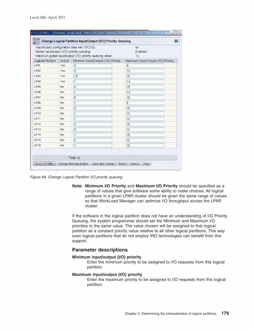
Note: Minimum I/O Priority and Maximum I/O Priority should be specified as arange of values that give software some ability to make choices. All logicalpartitions in a given LPAR cluster should be given the same range of valuesso that WorkLoad Manager can optimize I/O throughput across the LPARcluster.
If the software in the logical partition does not have an understanding of I/O PriorityQueuing, the system programmer should set the Minimum and Maximum I/Opriorities to the same value. The value chosen will be assigned to that logicalpartition as a constant priority value relative to all other logical partitions. This wayeven logical partitions that do not employ IRD technologies can benefit from thissupport.
Parameter descriptionsMinimum input/output (I/O) priority
Enter the minimum priority to be assigned to I/O requests from this logicalpartition.
Maximum input/output (I/O) priorityEnter the maximum priority to be assigned to I/O requests from this logicalpartition.
Figure 48. Change Logical Partition I/O priority queuing
Level 04b, April 2011
Chapter 3. Determining the characteristics of logical partitions 179
Moving unshared channel pathsYou can move reconfigurable channel paths owned by one LP to another LP.
Moving unshared channel paths from a z/OS system1. Select the LP that owns the channel path to display channel path information for
the LP.
2. Move the channel path from the z/OS console.
a. Enter CF CHP(nn),OFFLINE, where nn is the number of the desired channelpath, from the z/OS operator console that has the reconfigurable channelpath online.
b. Enter CF CHP(nn),ONLINE, where nn is the number of the desired channelpath, from the z/OS operator console that is the target LP.
Notes:
1) If a channel path is configured offline while the LP is isolated andremains offline when you change the LP’s isolation status from enabledto disabled, the channel path must be configured offline again. See“Releasing reconfigurable channel paths.”
2) If the channel path you want to move is currently assigned to adeactivated LP, you must configure it offline from the hardware console.
3) If the LP is not running a system control program that supports channelpath configuration commands, you can move the channel path from thehardware console.
Moving a channel path from the hardware console1. Select the LP that owns the channel path to display channel path information for
the LP.
2. Select a reconfigurable channel path from the CHPIDs work area. Drag anddrop the CHPID on the Reassign Channel Path task available from the CHPIDOperations task list.
3. The Reassign a Channel Path panel displays the targeted channel path, thecurrent owning LP, and a list of target LPs to which you can reassign thechannel path. Select the LP to which you want to reassign the channel path.
4. Click on the Reassign push button and confirm the action to release the channelpath.
5. When the “Requested operation is complete” message appears, click on the OKpush button.
Releasing reconfigurable channel pathsUse this procedure when the owning LP has LP isolation enabled.
1. Select the LP that owns the channel path to display channel path information forthe LP.
2. Select a reconfigurable channel path from the CHPIDs work area. Drag anddrop the CHPID on the Release task available from the CHPID Operations tasklist.
A Confirm the Action panel will display warning you that the channel paths willbe released and made available for reassignment to other LPs. Confirming theaction will release the channel path and a “Requested operation is complete”message will display. Click on the OK push button to complete the task.
Level 04b, April 2011
180 PR/SM Planning Guide

Configuring shared channel pathsVerify the status of the channel path for each LP to which you plan to configure thechannel path by opening each LP’s CHPIDs Work Area.
Enter CF CHP(nn),ONLINE (where nn is the number of the desired CHPID) fromeach z/OS operator console to which the CHPID is to be brought online.
If the operating system running in the LP is not z/OS, use the Configure On/Off taskavailable from the CHPID Operations task list to configure the CHPID online. Theshared channel path will be physically configured when the first LP configures thechannel path online.
Note: Dynamically managed channel paths can be configured Off but cannot beconfigured On from the Support Element’s CHPID Operations task list.
Deconfiguring shared channel pathsVerify the status of the channel path for each LP to which you plan to configure thechannel path by opening each LP’s CHPIDs Work Area.
Enter CF CHP(nn),OFFLINE (where nn is the number of the desired CHPID), fromeach z/OS operator console from which the CHPID is to be taken offline.
If the operating system running in the LP is not z/OS, use the Configure On/Off taskavailable from the CHPID Operations task list to configure the CHPID offline. Theshared channel path will be physically deconfigured when the last LP that had thechannel path online configures it offline.
Removing shared channel paths for service1. Enter (from the z/OS console that has the shared channel path online) CF
CHP(nn) OFFLINE, where nn is the number of the desired CHPID.
2. Use the Toggle all off option in the Configure On/Off task available from theCHPID Operations task list to remove the CHPID.
The Toggle all off option detaches the CHPID from all LPs that it is currentlyattached to regardless of the target LP. A CHPID that is shared by multiple LPsis detached from all LPs without forcing you to detach it individually from eachLP.
Toggle all off is also valid for unshared CHPIDs and it is mutually exclusive ofthe Release task.
3. Use the Service On/Off task available from the CHPID Operations task list toremove the CHPID.
Changing logical partition definitionsYou can make changes to LP definitions that are available dynamically to a runningLP or that are available at the next LP activation.
Changes available dynamically to a running LPThe following changes are available dynamically to a running LP:
v Using the Change Logical Partition Controls task, you can change the followingLP definitions:– Initial processing weight
Level 04b, April 2011
Chapter 3. Determining the characteristics of logical partitions 181

– Minimum processing weight– Maximum processing weight– WorkLoad Manager enablement– Processor weight capping– Processor running time (globally applicable to logical CPs of all shared LPs)– Global enablement of event-driven dispatching– Defined capacity
v Using the Change Logical Partition Input/Output (I/O) Priority Queuing Controlstask, you can change the following LP definitions:– Minimum input/output (I/O) priority– Maximum input/output (I/O) priority
v Using the Change Logical Partition Security task, you can change the followingLP definitions:– Global performance data control– Input/Output configuration control– Cross partition authority– Logical partition isolation– Basic counter set authorization control– Problem state counter set authorization control– Crypto activity counter set authorization control– Extended counter set authorization control– Coprocessor group counter sets authorization control– Basic sampling authorization control
v Using the Logical Processor Add task, you can do the following:– Increased the reserved value for a processor (general, zAAP, zIIP, IFL, etc)– Add a new processor type not yet in use for that partition– increase the initial value for a given processor type– Can change the running system or save the changes to profiles.
v Using the Change Logical Partition Cryptographic Controls task, you can:– Add a crypto adapter to a partition for the first time– Add a crypto adapter to a partition already using crypto adapters– Remove a crypto adapter from a partition– Zeroize, or clear the cryptographic secure keys for a given usage domain.
Changes available at the next LP activationThe following changes are available at the next LP activation:
v Use the IOCP RESOURCE statement to specify the MIF image ID numbersassigned to the LPs. The only way to change the specified MIF image IDnumbers is by creating a new IOCDS.
v Use the Partitions page in the reset profile to change the:– LP automatic activation order
v Use the General page in the image profile to change the:– Logical partition identifier– Mode of the LP– Enablement of the Logical partition time offset
v Use the Processor page in the image profile to change the:– Number of CPs, ICFs, IFLs, zAAPs, or zIIPs– Whether or not CPs are dedicated to an LP– Weight capping– WorkLoad Manager enablement– Initial processing weight– Initial capping enablement– Minimum processing weight
Level 04b, April 2011
182 PR/SM Planning Guide

– Maximum processing weight
v Use the Options page in the image profile to change the:– Minimum input/output (I/O) priority– Maximum input/output (I/O) priority– Defined capacity
v Use the Security page in the image profile to change the:– Global performance data control– Input/output configuration control– Cross partition authority– Logical partition isolation– Basic counter set authorization control– Problem state counter set authorization control– Crypto activity counter set authorization control– Extended counter set authorization control– Coprocessor group counter sets authorization control– Basic sampling authorization control
v Use the Storage page in the image profile to change the:– Central storage definitions– Expanded storage definitions
v Use the Time Offset page in the image profile to change the:– Logical partition time offset
v Use the Load page in the image or load profile to change the:– Automatic load data
v Use the Crypto page in the image profile to update the:– Control domain index– Usage domain index– Cryptographic Candidate List– Cryptographic Online List
Changes available at the next Power-On Reset (POR)The following changes are available at the next power-on reset.v Use the Options page in the reset profile to change the:
– Global enablement of input/output (I/O) priority queuing– Processor running time interval– Enablement of event-driven dispatching– Automatic input/output (I/O) interface reset
Level 04b, April 2011
Chapter 3. Determining the characteristics of logical partitions 183

Level 04b, April 2011
184 PR/SM Planning Guide

Chapter 4. Operating logical partitions
Overview . . . . . . . . . . . . . . . . . . . . . . . . . . 186Available operator controls . . . . . . . . . . . . . . . . . . . . 186Operator controls not available . . . . . . . . . . . . . . . . . . 188Operator tasks . . . . . . . . . . . . . . . . . . . . . . . . 189
Editing activation profiles . . . . . . . . . . . . . . . . . . . . 189Reset profiles . . . . . . . . . . . . . . . . . . . . . . . 189Image profiles . . . . . . . . . . . . . . . . . . . . . . . 189Load profiles . . . . . . . . . . . . . . . . . . . . . . . 189
Activating a CPC. . . . . . . . . . . . . . . . . . . . . . . 189Activating an LP . . . . . . . . . . . . . . . . . . . . . . . 189Performing a load on an LP or activating a load profile . . . . . . . . . 189Deactivating an LP . . . . . . . . . . . . . . . . . . . . . . 190Locking and unlocking an LP . . . . . . . . . . . . . . . . . . 190Deactivating a CPC. . . . . . . . . . . . . . . . . . . . . . 191
Level 04b, April 2011
© Copyright IBM Corp. 2008, 2010 185

OverviewThis chapter provides information on operating the hardware system.
Sample tasks and panels explained in this chapter reference tasks and panelsavailable from the Support Element console of a System z10. However, detailedprocedures for operator tasks and accurate task and panel references are explainedin the System z10 Support Element Operations Guide, SC28-6879.
Available operator controlsThe following tasks are available when logged on in system programmer mode:
Task Tasks List
Hardware System MessagesOperating System Messages
AllAll
ActivateReset NormalDeactivateGroupingActivity
Daily TasksDaily TasksDaily TasksDaily TasksDaily Tasks
Start AllStop AllReset NormalReset ClearLoadPower-on ResetLoad from Removable Media or Server
CPC RecoveryCPC RecoveryCPC RecoveryCPC RecoveryCPC RecoveryCPC RecoveryCPC Recovery
Service StatusView Service HistoryCheckout TestsReport a ProblemTransmit Service DataDump LPAR DataDelete LPAR Dump DataDump Machine Loader DataOffload Virtual Retain Data To HMC DVDGlobal OSA StatusInfiniBand multiport Status and ControlPerform Problem Analysis
ServiceServiceServiceServiceServiceServiceServiceServiceServiceServiceServiceService
Define Clonable Internal Code LevelsSystem InformationForce Channel Internal Code ChangeAuthorize Internal Code ChangesAlternate Support ElementQuery Coupling Facility ReactivationsCheck DependenciesQuery Channel/Crypto Configure On/Off PendingQuery Internal Code Changes Pending
Power-On ResetSelective Channel Path ControlsSpecify Concurrent Upgrade Sync Point
Change ManagementChange ManagementChange ManagementChange ManagementChange ManagementChange ManagementChange ManagementChange ManagementChange Management
Change ManagementChange Management
Remote ServiceCustomer Information
CPC Remote CustomizationCPC Remote Customization
Level 04b, April 2011
186 PR/SM Planning Guide

Task Tasks List
Customize/Delete Activation ProfilesAutomatic ActivationCustomize Scheduled OperationsChange Logical Partition ControlsChange Logical Partition SecurityStorage InformationSystem Activity ProfilesEnable/Disable Dynamic Channel SubsystemView LPAR Cryptographic ControlsExport/Import Profile DataEnable I/O Priority QueuingChange Logical Partition I/O Priority QueuingChange LPAR Cryptographic ControlsChange LPAR Group ControlsLogical Processor Add
CPC Operational CustomizationCPC Operational CustomizationCPC Operational CustomizationCPC Operational CustomizationCPC Operational CustomizationCPC Operational CustomizationCPC Operational CustomizationCPC Operational CustomizationCPC Operational CustomizationCPC Operational CustomizationCPC Operational CustomizationCPC Operational CustomizationCPC Operational CustomizationCPC Operational CustomizationCPC Operational Customization
Perform Model ConversionTransmit Vital Product DataView Frame LayoutSystem (Sysplex) TimeInput/Output (I/O) ConfigurationView Hardware ConfigurationChannel PCHID AssignmentCleanup DiscontinuanceCryptographic ConfigurationCryptographic ManagementDisplay Adapter IDNPIV ConfigurationPrepare System for DiscontinuanceSystem Input/Output Configuration Analyzer
CPC ConfigurationCPC ConfigurationCPC ConfigurationCPC ConfigurationCPC ConfigurationCPC ConfigurationCPC ConfigurationCPC ConfigurationCPC ConfigurationCPC ConfigurationCPC ConfigurationCPC ConfigurationCPC ConfigurationCPC Configuration
StartStopDisplay or AlterPSW RestartStop on CP Address MatchInterruptStore Status
CP ToolboxCP ToolboxCP ToolboxCP ToolboxCP ToolboxCP ToolboxCP Toolbox
Configure On/OffReleaseShow LEDChannel Problem DeterminationFCP NPIV On/Off
CHPID OperationsCHPID OperationsCHPID OperationsCHPID OperationsCHPID Operations
Configure On/OffService On/OffAdvanced FacilitiesChannel Problem Determination
Crypto Service OperationsCrypto Service OperationsCrypto Service OperationsCrypto Service Operations
Configure On/OffReleaseService On/OffShow LEDAdvanced FacilitiesReassign Channel PathChannel Problem Determination
Channel OperationsChannel OperationsChannel OperationsChannel OperationsChannel OperationsChannel OperationsChannel Operations
Level 04b, April 2011
Chapter 4. Operating logical partitions 187

Operator controls not availableThe following tasks are not available when logged on in system programmer mode:v Enable TODv Change Operation Ratev Stop on I/O Address Matchv Stop on I/O Eventv Stop on PSW Eventv Trace
Level 04b, April 2011
188 PR/SM Planning Guide

Operator tasks
Editing activation profilesYou can edit reset, image, and load profiles for configurations using theCustomize/Delete Activation Profiles task available from the CPC OperationalCustomization tasks list.
Reset profilesUse the reset profile to:v Select an IOCDSv Optionally specify an LP activation sequencev Enable I/O Priority Queuing.
You can select an IOCDS using the General page of the reset profile. To specify anoptional LP activation sequence, use the Partitions page of the reset profile.
Image profilesUse the image profile to:v Define LP characteristicsv Optionally specify automatic load settings.
To define LP characteristics, use the General, Processor, Security, Storage,Options, Crypto, and Time Offset pages of the image profile (see “Defining logicalpartitions” on page 151). To specify optional automatic load settings, use the Loadpage of the image profile (see “Load information” on page 171).
Load profilesIf you are not using the image profile to specify load options for an LP, use the loadprofile.
Activating a CPCTo activate a CPC, locate the CPC icon and open the Activate task available fromthe Daily Tasks task list. This task will activate the hardware system and, if LPactivation sequence is enabled for LPs, will activate those LPs in the order specifiedin the reset profile for the CPC. You can also automatically load the LP’s operatingsystem as specified in the image profile for the LP.
Activating an LPTo activate an LP, locate the LP icon, and open the Activate task available from theDaily Tasks list. This task will activate the LP and, if automatic load is specified foran LP, will automatically load the LP’s operating system as specified in the imageprofile for the LP.
Performing a load on an LP or activating a load profilePerform a load on an LP or activate a load profile for an LP by locating the LP iconfor a previously activated LP and opening the Customize/Delete Activation Profilestask available from the CPC Operational Tasks list.
Select or, if necessary, customize or create a load profile for the LP. Assign the loadprofile to the LP’s activation profile and exit the Customize/Delete Activation Profilestask, saving your changes. Next, locate the LP icon and open the Activate taskavailable from the Daily Tasks list.
Level 04b, April 2011
Chapter 4. Operating logical partitions 189

Also, in recovery situations, you can locate the LP icon and open the Load taskavailable from the CPC Recovery tasks list.
Deactivating an LPTo deactivate an LP, locate the LP icon and open the Deactivate task available fromthe Daily Tasks list. This task will deactivate the LP and any operating systemrunning in the LP.
Locking and unlocking an LPLock an LP by double-clicking on the CPC image icon representing the LP to openits Detail page. Set the Lockout Disruptive Tasks radio button to Yes and select theApply button.
You can use this same procedure to unlock an LP by setting the Lockout DisruptiveTasks radio button to No and applying the setting.
Locking an LP can prevent accidentally performing disruptive tasks on an LP. Youcan lock the following system programmer mode tasks:
v Daily tasks– Activate– Reset Normal– Deactivate
v CPC Recovery tasks– Start all– Stop all– Reset Normal– Reset Clear– Load– Power-on Reset– Load from Removable Media or Server
v Service tasks– Checkout Tests– Dump Machine Loader Data
v Change Management tasks– Define Clonable Internal Code Levels– Query Coupling Facility Reactivations
v CPC Operational Customization tasks– Change Logical Partition Controls– Change LPAR Group Controls– Change Logical Partition Security
v CPC Configuration
– System (Sysplex) Time
v CP Toolbox tasks– Start– Stop– Display or Alter– PSW Restart– Interrupt– Store Status
v CHPID Operations tasks– Configure On/Off– Release– Channel Problem Determination
Level 04b, April 2011
190 PR/SM Planning Guide

v Crypto Service Operations tasks– Configure On/Off– Service On/Off– Advanced Facilities– Channel Problem Determination
v Channel Operations tasks– Configure On/Off– Release– Service On/Off– Advanced Facilities– Reassign Channel Path– Channel Problem Determination
Deactivating a CPCTo deactivate a CPC, locate the CPC icon and open the Deactivate task availablefrom the Daily Tasks list. This task will deactivate the CPC and any activated LPsand their associated operating systems.
Level 04b, April 2011
Chapter 4. Operating logical partitions 191

Level 04b, April 2011
192 PR/SM Planning Guide

Chapter 5. Monitoring the activities of logical partitions
Overview . . . . . . . . . . . . . . . . . . . . . . . . . . 194Monitoring logical partition activity . . . . . . . . . . . . . . . . . 194
Reviewing current storage information . . . . . . . . . . . . . . . 194Reviewing and changing current channel status . . . . . . . . . . . 196Reviewing and changing current logical partition controls . . . . . . . . 196Reviewing and adding logical processors . . . . . . . . . . . . . . 196Reviewing and changing current logical partition group controls . . . . . 197Reviewing and changing current logical partition security . . . . . . . . 199Reviewing and changing current logical partition cryptographic controls 200
View LPAR cryptographic controls . . . . . . . . . . . . . . . 200Changing LPAR cryptographic controls . . . . . . . . . . . . . 200Cryptographic configuration - usage domain zeroize . . . . . . . . . 204
Reviewing current system activity profile information. . . . . . . . . . 205Reviewing and changing logical partition I/O priority values . . . . . . . 205
Logical partition performance . . . . . . . . . . . . . . . . . . . 207RMF LPAR management time reporting . . . . . . . . . . . . . . 207Dedicated and shared central processors. . . . . . . . . . . . . . 208CPENABLE . . . . . . . . . . . . . . . . . . . . . . . . 208Start Interpretive Execution (SIE) performance . . . . . . . . . . . . 208
Recovery strategy . . . . . . . . . . . . . . . . . . . . . . . 209Operation considerations . . . . . . . . . . . . . . . . . . . . 209Application preservation . . . . . . . . . . . . . . . . . . . . 210Transparent sparing . . . . . . . . . . . . . . . . . . . . . 210
Level 04b, April 2011
© Copyright IBM Corp. 2008, 2010 193
OverviewThis chapter describes the panels and tasks that can be used to monitor LP activity.It also provides LP performance information and provides guidelines andsuggestions for planning a recovery strategy for operation.
Monitoring logical partition activityIn addition to viewing LP information located in the General, Processor, Security,Storage, Load, and Channels pages of an LP’s reset, image, and load profiles, youcan use the following tasks to further monitor LP activity:v Current storage informationv Current channel informationv Current System activity profile information
Reviewing current storage informationUse the Storage Information task available from the CPC Operational Customizationtasks list to open the Storage Information task to display LP storage information forLPs currently activated on the CPC.
For this example, assume the amount of customer storage is 49152 MB (48 GB).The amount of addressable central storage is 8388608 MB (8192 GB). The amountof addressable central storage used by hardware system area (HSA) is 65536 MB,leaving 8323072 MB of addressable storage for allocation to LPs.
Level 04b, April 2011
194 PR/SM Planning Guide

Figure 49. Storage information task. This example shows two partitions active. LP2 has 4096MB of initial central storage and 2048 MB of initial expanded storage. LP1 has 1024 MB ofinitial central storage, 1024 MB of reserved central storage and 1024 MB of initial expandedstorage. LP1 was activated first, without any expanded storage. Then, LP2 was activated andLP1 was activated again with expanded storage.
Note: The central storage addressability required for LP1’s expanded storage is notnecessarily contiguous to the CS addressability for LP1's initial or reserved centralstorage.
Level 04b, April 2011
Chapter 5. Monitoring the activities of logical partitions 195

Reviewing and changing current channel statusUse the tasks available on the CHPID Operations task list to display and modifychannel status information in an LP’s CHPID work area.
Reviewing and changing current logical partition controlsUse the Change Logical Partition Controls task available from the CPC OperationalCustomization tasks list to display and modify LP controls for an LP.
Reviewing and adding logical processorsThe Logical Processor Add task allows you to select logical processor definitions tobe changed dynamically on the system, in the image profile, or both. Dynamicchanges will take effect without performing a reactivation of the logical partition.This tasks allows you to:
v Increase the initial and/or reserved values for installed logical processor type(s)
v Add a reserved value and set weight and capping indicators for logical processortype(s) that have not yet been installed and have no reserved CPs defined
v Increase the reserved value for logical processor type(s) that have not beeninstalled and already have reserved CP(s) defined
The partition status (active/inactive) is indicated in the panel title, along with thelogical partition name. If the logical partition is active, the current settings are
Figure 50. Change logical partition controls page. The Current Weight for an active shared LP will always shownonzero. For non-WLM managed logical partitions, the Current Weight will always be equal to the Initial ProcessingWeight. The Current Weight for WLM managed logical partitions will be whatever value WLM has currently assigned tothe LP. Current Capping will always be indicated for an active LP that has Initial Capping. Current capping will also beindicated for an LP which has been dynamically soft-capped by the Workload Manager (WLM).
Level 04b, April 2011
196 PR/SM Planning Guide

displayed. If the logical partition is inactive, the settings contained in the imageprofile will be displayed.
Reviewing and changing current logical partition group controlsChange LPAR Group Controls allows you to define LPAR group capacity limits,allowing you to specify one or more groups of LPARs on a server, each with its owncapacity limit. This is designed to allow z/OS to manage the groups in such a waythat the sum of the LPARs' CPU utilization within a group will not exceed thegroup's defined capacity. Each Logical partition in a group can still optionallycontinue to define an individual logical partition capacity limit.
LPAR group capacity limit requires that all logical partitions to be managed in thegroup be running z/OS or z/OS.e V1.8 or later. LPAR group capacity limits may helpprovision a portion of a System z10 server to a group of logical partitions allowingthe CPU resources to float more readily between those logical partitions, resulting inmore productive use of "white space" and higher server utilization.
Figure 51. Logical processor add. This is an active, ESA mode partition. There are currentlyonly CPs defined to the partition, so only reserved can be increased for zAAP and zIIP.
Level 04b, April 2011
Chapter 5. Monitoring the activities of logical partitions 197

For information about creating a group, see “Creating a logical partition groupprofile” on page 176. For detailed information about grouping objects for activation,see the System z10 Support Element Operations Guide.
For information about how workload management and workload license chargesrelate to the Group Capacity setting, see z/OS MVS Planning: WorkloadManagement, SA22-7602.
Figure 52. Change LPAR group controls
Level 04b, April 2011
198 PR/SM Planning Guide

Reviewing and changing current logical partition securityUse the Change Logical Partition Security task available from the CPC OperationalCustomization tasks list to display and modify security controls for an LP.
Figure 53. Change logical partition security page
Level 04b, April 2011
Chapter 5. Monitoring the activities of logical partitions 199

Reviewing and changing current logical partition cryptographiccontrols
View LPAR cryptographic controlsUse the View LPAR Cryptographic Controls task available from the CPCOperational Customization tasks list to display crypto characteristics for an LP. TheSummary tab displays the current crypto configuration settings for all active andinactive partitions in the CPC. (The inactive partition information displayed is aresult of the settings selected in the Image Activation profile.) The tab with thename of the partition displays the current crypto configuration for that activepartition.
Changing LPAR cryptographic controlsUse the Change LPAR Cryptographic Controls task to make changes to the cryptoconfiguration of an active partition without affecting the operating status of thepartition. This allows you to update your crypto configuration without reactivating thelogical partition. You can add cryptos to a partition, delete cryptos from a partition,
Figure 54. View LPAR cryptographic controls window (summary tab)
Figure 55. View LPAR cryptographic controls (showing tab containing crypto configurationinformation for an active partition)
Level 04b, April 2011
200 PR/SM Planning Guide

and/or move a crypto from one partition to another using the following task:
There are requirements for adding, removing and moving a crypto:
v The crypto that is assigned to this partition must be configured offline before theremoval of the crypto from the partition can be done. If the crypto was operatingas a coprocessor, and a removal of a crypto is being done, the user is given theopportunity to remove the cryptographic keys from the partition associated withthe selected usage domain, using the usage domain zeroize function.
v If the crypto is not online to the partition, but the associated PCHID isonline/operating, the usage domain zeroize action can immediately be done. Ifthe crypto assigned to the partition and the PCHID are both offline, the usagedomain zeroize action will be pending until the next time this crypto is broughtonline.
v To move a crypto from one partition to another requires you to perform two steps.First, remove the crypto from the first partition and then add it to the secondpartition.
v After a crypto is added to a partition, the crypto needs to be brought online usingthe config On/Off task found in Crypto Operations.
Note: Changes made using the Change LPAR Cryptographic Controls task can bemade to both active and inactive partitions. When performed on an inactivepartition, the changes are made to the image activation profile, since thepartition is not active.
Figure 56. Change LPAR cryptographic controls
Level 04b, April 2011
Chapter 5. Monitoring the activities of logical partitions 201

The cryptographic domain index table displays the current settings of the usagedomain indexes and control domain indexes which can be modified in the logicalpartition and/or the image profile.
Control DomainA logical partition's control domains are those cryptographic domains forwhich remote secure administration functions can be established andadministered from this logical partition. This logical partition’s controldomains must include its usage domains. For each index selected in theusage domain index list, you must select the same index in the controldomain index list.
Usage DomainA logical partition’s usage domains are domains in the cryptos that can beused for cryptographic functions. The usage domains cannot be removed ifthey are in use by the partition. The usage domains you select for thislogical partition must also be selected in the control domain index.
The cryptographic list table displays the current settings of the cryptographiccandidate list and cryptographic online list settings which can be modified in thelogical partition and/or the image profile:
Cryptographic Candidate ListThe candidate list identifies which cryptos are assigned to the active logicalpartition. Cryptos cannot be removed if they are online to this partition.
Cryptographic Online List (from profile)The online list identifies which cryptos will be brought online at the nextactivation. Changes to the online list do not affect the running system.
To commit your changes, use one of the following:
Save to ProfilesSelect this if you want new settings to take effect whenever the logicalpartition is activated with the modified profile. This changes thecryptographic settings in the logical partition's image profile. The settingstake effect whenever the logical partition is activated with its image profile.
Change Running SystemSelect this if you want the new settings to take effect in the active logicalpartition immediately. This changes the cryptographic settings in the logicalpartition without reactivating the partition. The new settings remain in effectfor the logical partition until you either dynamically change the settingsagain or reactivate the partition.
Note: This button can be used for an active logical partition only. For aninactive partition, this button is disabled.
Save and ChangeSelect this if you want the new settings to take effect immediately andwhenever the logical partition is activated with the modified profile. Saveand Change:
v Saves a logical partition’s cryptographic control settings in its imageprofile. The settings take effect whenever the logical partition is activatedwith its image profile.
v Changes the cryptographic settings in the logical partition withoutreactivating the partition. The new settings remain in effect for the logicalpartition until you either dynamically change the settings again orreactivate the partition.
Level 04b, April 2011
202 PR/SM Planning Guide

Note: This button can be used for an active logical partition only. For aninactive partition, this button is disabled.
Reset Select this to revert the settings back to their original values.
When a crypto with it's associated usage domains are removed from a partition, thispartition will no longer have access to the cryptographic keys. But if this crypto isthen assigned to a different partition utilizing the same usage domains as before,then this new partition will have access, possibly unintentional access, to thecryptographic keys. Therefore, when a crypto is removed from an active partition,the Usage Domain Zeroize panel is displayed, providing the opportunity to clear thecryptographic keys associated with the given usage domain(s).
Note: If the crypto device you remove is the last remaining one, you will receive acautionary note that all cryptographic candidates have been removed fromthe partition, which will remove the partition's access to all cryptos.
Figure 57. Usage domain zeroize
Figure 58. Message received from change LPAR cryptographic controls
Level 04b, April 2011
Chapter 5. Monitoring the activities of logical partitions 203

Cryptographic configuration - usage domain zeroizeThe opportunity to clear or zeroize the cryptographic keys associated with a usagedomain is available when removing a crypto using the Change LPAR CryptographicControls task. The zeroize of the cryptographic keys can also be performed usingthe Cryptographic Configuration task.
The Cryptographic Configuration window can be used to configure and monitor thecryptos that are installed on your system. Use this window to perform various tasks,including:
v Checking the status and details of your cryptos.
v Testing the Random Number (RN) generator of the crypto.
v Manually zeroizing cryptos and erasing configuration data from the SupportElement.
v Importing and activating the UDX configuration for both Crypto Express2 andCrypto Express3
v Indicating whether to permit TKE commands for the selected crypto.
v Indicating the crypto type configuration for the Crypto Express2 or CryptoExpress3 feature.
The removal of a crypto from a partition could make those cryptographic keysavailable to another LPAR, if the crypto and usage domains are then reassigned toa new partition. Such an exposure can occur when:
v removing the crypto from the candidate list in the Activation profile, thenreassigning the crypto to another active partition.
v moving a crypto using the Change LPAR Cryptographic Controls task, asdiscussed earlier in this chapter.
The Usage Domain Zeroize function as part of the Cryptographic Configuration taskoffers the opportunity to clear the cryptographic keys when desired, not just whenthe cryptographic settings are modified using the Change LPAR CryptographicControls task.
It is recommended that the usage domain zeroize be performed with the cryptooffline, but it is not required. When performing the usage domain zeroize with thecrypto offline, the zeroize of the usage domain index(es) selected is deferred untilthe selected crypto is configured online, using the Configure On/Off task, foundunder Crypto Operations.
On the Cryptographic Configuration window, select the crypto, and click UsageDomain Zeroize. The Usage Domain Zeroize window displays:
Figure 59. Cryptographic configuration window
Level 04b, April 2011
204 PR/SM Planning Guide

On the Usage Domain Zeroize window, select the usage domain index(es) thathave the cryptographic keys you wish to zeroize, and then click Zeroize. Thezeroize of the Usage Domain Index(es) is deferred until the selected Cryptographicnumber is configured online (Configure On). When the selected cryptographicnumber is configured online, the selected Usage Domain indexes will be cleared ofcryptographic keys.
Reviewing current system activity profile informationUse the System activity profiles task available from the Daily Tasks list to open aSystem activity information window. Locate the System Activity profile, whichdisplays the system activity information you want to view.
Reviewing and changing logical partition I/O priority valuesUse the Change Logical Partition I/O Priority Queuing task available from the CPCOperational Customization tasks list to display and modify I/O priority queuingvalues for one or more LPs.
Figure 60. Usage domain zeroize window
Level 04b, April 2011
Chapter 5. Monitoring the activities of logical partitions 205

Figure 61. Change Logical Partition I/O priority queuing window
Level 04b, April 2011
206 PR/SM Planning Guide

Logical partition performanceContact your IBM service representative for assistance in planning configurationcapacity requirements.
The performance of LPs depends on:v The operating systems and their workloadsv The configuration of the LPsv The configuration of the CPCv The performance tuning parameters
You can contact an service representative who has access to a proprietary IBMperformance planning tool (LPARCE from CPSTOOLS at WSCVM) to assist you inthis task.
RMF LPAR management time reportingRMF processor utilization reporting includes LPAR Management Time on thePartition Data Report. RMF provides information about all shared logical CPs thatremain active for the duration of the reporting interval. RMF can also be run on asingle LP if additional information is required.
There are two types of LPAR management time reporting: time spent managing theLP, and time spent managing the physical configuration. With LPAR ManagementTime reporting, the time used to manage an LP can be separated from the timeused by the workload in an LP.
Figure 62. ETR increasing with CPU utilization
Level 04b, April 2011
Chapter 5. Monitoring the activities of logical partitions 207

Figure 62 on page 207 is an example of how information from the enhanced RMFLPAR Management Time reports can be used. This example shows the LPARManagement Time and the partition effective dispatch time for each LP. As CPUutilization increases, LPAR management time decreases, and the externalthroughput rate (ETR) increases.
Using the RMF report, CPU-utilization calculations can be based on an LP’seffective dispatch time. The effective dispatch time can be determined by excludingLPAR Management Time from the time that a physical CP is assigned to a logicalCP.
Note: For more information about RMF support, the RMF Partition Data Report,and LPAR Management Time see the Resource Measurement Facility User’sGuide.
Dedicated and shared central processorsGenerally, LPs with dedicated CPs require fewer processing resources. The internalthroughput rate (ITR) of LPs with dedicated CPs is higher than that of identicallydefined LPs with shared CPs. Also, IBM recommends that dedicated processors(ICFs or CPs) be used in a coupling facility partition that is used in a productionconfiguration.
Generally, the capability to recognize CP resources that are not used and tobalance workloads can result in an improved ETR for LPs with shared CPs. Inparticular, for workloads that exhibit fluctuations in processing demands, theconsolidation of several systems as LPs with shared CPs on a CPC can improveresponsiveness and increase ETR.
CPENABLEThe z/OS CPENABLE parameter can be used to provide selective enablement forI/O interrupts. On System z10 CPCs, the best ITR is achieved when the fewest CPsare enabled for I/O interrupts. Selective enablement for I/O and the CPENABLEparameter are described in the z/OS MVS Initialization and Tuning Reference,SA22-7592.
For logical partitions using dedicated processors, IBM recommends aCPENABLE=(10,30) setting to minimize the number of CPs handling I/O interruptsin an LP.
A CPENABLE=(0,0) setting, enabling all CPs to handle I/O interrupts, can causeperformance degradation for logical partitions with dedicated CPs.
For logical partitions sharing CP resources, IBM recommends aCPENABLE=(10,30) setting. There is a negligible ITR impact between aCPENABLE=(0,0) setting versus a CPENABLE=(10,30) setting for logical partitionssharing CP resources.
Start Interpretive Execution (SIE) performancePR/SM implementation uses CPC hardware mechanisms that are also used toimplement the SIE facility when operating in ESA/390 mode. Therefore, if SIE isexecuted in an LP, SIE performance is reduced relative to operation in ESA/390mode. The performance reduction depends on the frequency of SIE invocation andshould be evaluated for each application.
Level 04b, April 2011
208 PR/SM Planning Guide

Recovery strategyRecovery planning requires that the appropriate planners and technical supportpersonnel understand the recovery strategy.
In planning for recovery, consider the following guidelines:
v Recovery is considered successful if an LP is able to perform useful work andcritical application programs remain operational (even if one or more LPs aredisabled) after a failure occurs. Recoverability depends on the extent andlocation of a failure and the ability of the operating system to handle the failure.
v Develop a recovery strategy for the specific installation that addresses thespecific hardware and applications of that installation. For example, if a failureoccurs that might disrupt multiple LPs or a critical LP, the operator should be ableto determine what must remain active and what can be deactivated, and toperform the appropriate recovery procedures.
v The operator should follow established local procedures for reporting problemsand for performing recovery procedures. It is recommended that recoveryprocedures be ranked from least to most disruptive. The operator should knowwhat procedures to follow if any or all LPs do not respond to the recovery actionsdirected to it.
v Assign channel paths to LPs as described in the guidelines under “Guidelines forsetting up the I/O configuration” on page 33.
v Define resources to LPs so that any hardware failure has a minimal impact onany LP that must remain active.
For example, the failure of a physical CP causes the temporary loss of the logicalCP that was dispatched on the physical CP. The LP owning that logical CP maycontinue running if it was running on an LP with at least two CPs and if theoperating system can recover from a CP failure.
Operation considerationsIf an individual LP is affected, the following recovery actions (ranked from least tomost disruptive) should be considered when planning recovery procedures.
v If an affected LP continues to operate with a problem, allow it to do so.
v If the operating system in an LP remains active but processing is interrupted,consider the applicability of a restart or IPL.
v Perform a stand-alone dump and IPL the operating system.
v Perform an orderly shutdown of the operating system in an affected LP. If the LPis not critical, allow the other LPs to continue.
If all LPs are affected, or if a critical LP is affected and did not respond to therecovery actions directed only to it, the following recovery actions (also ranked fromleast to most disruptive) should be considered when planning recovery procedures.
v Perform an orderly shutdown of all the operating systems. Activate the LPs andIPL the operating systems.
v Perform an orderly shutdown of all the operating systems. Perform the mostappropriate recovery action (for example, in response to a hardware failure).Perform a power-on reset.
v If a power-on reset fails to initialize the LPs, perform a power-on reset to attempta recovery. IPL the most critical operating system.
Level 04b, April 2011
Chapter 5. Monitoring the activities of logical partitions 209

Application preservationThe application preservation facility enhances system availability and providesadditional protection from CP failures. This support is available on System z10 CPCmodels with two or more central processors (CPs). Using application preservation,the system moves an application in process from a failing CP to another operatingCP. Both the CP failure and the move are transparent to the application.
There are no software corequisites when running with shared CPs. For LPs usingshared CPs, even 1-way LPs can survive a CP failure without experiencing a failureto the application or the LP, providing the 1-way LP is being run on a model withmore than one physical CP.
Transparent sparingTransparent sparing takes LP recovery one step further by combining the benefitsof application preservation and concurrent CP sparing to allow for the transparentrecovery of an LP and its applications (including CF LPs). Transparent sparing useshardware to handle the recovery, requires no software support or operatorintervention, and is effective for both shared and dedicated LP environments.
Transparent sparing configures a spare PU (processor unit) to replace a failed CP,ICF, IFL, zAAP, zIIP or SAP. Each of the z10 EC models has 2 spare PUs. Thereare no dedicated spare PUs on the z10 BC.
Level 04b, April 2011
210 PR/SM Planning Guide
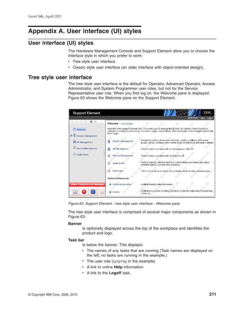
Appendix A. User interface (UI) styles
User interface (UI) stylesThe Hardware Management Console and Support Element allow you to choose theinterface style in which you prefer to work:
v Tree style user interface
v Classic style user interface (an older interface with object-oriented design).
Tree style user interfaceThe tree style user interface is the default for Operator, Advanced Operator, AccessAdministrator, and System Programmer user roles, but not for the ServiceRepresentative user role. When you first log on, the Welcome pane is displayed.Figure 63 shows the Welcome pane on the Support Element.
The tree style user interface is comprised of several major components as shown inFigure 63:
BannerIs optionally displayed across the top of the workplace and identifies theproduct and logo.
Task barIs below the banner. This displays:
v The names of any tasks that are running (Task names are displayed onthe left; no tasks are running in the example.)
v The user role (sysprog in the example)
v A link to online Help information
v A link to the Logoff task.
Figure 63. Support Element - tree style user interface - Welcome pane
Level 04b, April 2011
© Copyright IBM Corp. 2008, 2010 211

Navigation paneIs in the left portion of the window. This contains the primary navigationlinks for managing your system resources and the console. The items arereferred to as nodes.
Work paneIs in the right portion of the window. This displays information based on thecurrent selection from the navigation pane. For example, when Welcome isselected in the navigation pane, the Welcome content is displayed in thework pane, as shown in the example.
Status barIs in the bottom left portion of the window. This provides visual cues ofcurrent overall system status. It also contains a Status Overview icon whichmay be selected to display more detailed status information in the workpane.
Tree style navigation provides hierarchical views of system resources and tasksusing drill-down and launch-in-context techniques to enable direct access tohardware resources and task management capabilities. Figure 64 shows this.
The tree style user interface uses common terminology where possible. Forexample, instead of referring to a CPC, a more general term of server is used forthis interface. Similarly, in the tree style partitions are equivalent to images in theclassic style.
For panes other than the Welcome pane, the contents of the work pane on the rightportion of the window reflect your selections in the navigation pane on the left. Thetop portion of the work pane displays a table of objects based on your selection.The bottom portion of the work pane is called the tasks pad. Figure 64 shows this.
Figure 64. Server selected and task categories displayed
Level 04b, April 2011
212 PR/SM Planning Guide

Tasks padIs in the bottom portion of the work pane after you select an object in thenavigation pane, such as server, partition, channel, or crypto. The tasks padcontains a list of available task categories or tasks for the selected object.
Classic style user interfaceThe classic style user interface (classic interface) is the original user interface andis the default for the Service Representative user role. It has an object-orienteddesign. Figure 65 shows the classic style user interface for the Support Element.
You can directly manipulate the objects (such as CPCs) that are defined and beaware of changes to hardware status as they are detected. You can work with theobjects on the workplace using the mouse to select them. There are severaltechniques for manipulating objects and tasks. One way to do this is to left-click anobject to select it and double-click the task. An alternate method is the drag anddrop technique, which involves using the mouse to pick up one or more objects,dragging them to a task, and then dropping them. These techniques are examplesof what is known as direct manipulation.
Changing the user interface styleTo change from the tree style interface to classic style, perform the following steps:
1. In the navigation pane in the left portion of the window, click SE Management.
2. In the tasks pad in the bottom portion of the Work Pane, under Configuration,click User Settings.
3. Click the UI Style tab. This displays the User Style Information window.
4. Select Classic Style, and then click Apply.
Figure 65. Support Element - Classic style user interface
Level 04b, April 2011
Appendix A. User interface (UI) styles 213

5. Click OK to close the User Settings window.
To change from classic style back to tree style, perform the following steps:
1. Open User Settings (under Console Actions in the classic interface). TheUser Settings window is displayed.
2. Click the UI Style tab. The User Style Information window is displayed.
3. Select Tree Style, and then click Apply.
4. Click OK to close the User Settings window.
Level 04b, April 2011
214 PR/SM Planning Guide

Appendix B. Coupling facility control code support
Coupling facility control code is Licensed Internal Code (LIC) that supports thefollowing coupling facility limits:
Table 21. Coupling facility limits at different coupling facility code levels
Coupling Facility Limit
Coupling Facility Code Level
Level 16 Level 15 Level 14 Level 13 Level 12
Maximum number of CPs 16 16 16 16 16
Storage increment 1 MB 512 KB 256 KB 256 KB 256 KB
Structure ID limit 1023 1023 1023 1023 1023
Retry buffer limit 1799 1799 1799 1799 1559
Facility information 64 bytes 64 bytes 64 bytes 64 bytes 64 bytes
Maximum list elementcharacteristic 4 4 4 4 4
Maximum lock table entrycharacteristic 5 5 5 5 5
User identifier limit 32 32 32 32 32
Maximum data area elementcharacteristic 4 4 4 4 4
Local cache identifier limit 255 255 255 255 255
Storage class limit 63 63 63 63 63
Castout class limit 1024 1024 1024 1024 1024
Sublist Notification DelayLimit X'FFFFFFFF' N/A N/A N/A N/A
LegendMaximum number of CPs
Indicates the maximum number of CPs that can be used by acoupling facility logical partition.
Storage incrementIndicates the granularity with which storage allocation requests arerounded, to the amount shown in the table for a particular CFCClevel.
Structure ID limitCache and list structure ID. Effectively, this limit defines themaximum number of coupling facility structure instances that acoupling facility at this level may contain.
Retry buffer limitRetry buffer range upper limit.
Facility informationThis area contains coupling facility control code release and servicelevel information
Maximum list element characteristicThe size of a list structure list element in bytes equals 256 * (2 **list element characteristic), for example, 256 * (2**4) = 4K.
Level 04b, April 2011
© Copyright IBM Corp. 2008, 2010 215

Maximum lock table entry characteristicThe size of a lock table entry in bytes equals 2 ** lock table entrycharacteristic.
User identifier limitThe maximum number of users and list notification vectors that canbe attached to a list structure.
Maximum data area element characteristicThe size of a data area element in bytes equals 256 * (2 ** dataarea element characteristic, for example, 256 * (2**4) = 4K).
Local cache identifier limitThe maximum number of local caches that can be attached to acache structure.
Storage class limitStorage classes are in the range 1 to the value shown in the table.
Castout class limitCastout classes are in the range 1 to the value shown in the table.
Sublist Notification Delay Limit (SLNDL)The maximum time delay value that can be specified for a liststructure's Sublist Notification Delay. The Sublist Notification Delayis the time delay between the initial notification performed to aselected monitoring user in response to a sublist becomingnon-empty, and the subsequent notification(s) that are performed tothe remaining monitoring users.
Level 04b, April 2011
216 PR/SM Planning Guide

Appendix C. Developing, building, and delivering a certifiedsystem
This appendix is intended to provide guidance in setting up, operating, andmanaging a secure environment using System z10 PR/SM. It is primarily for thesecurity administrator, but can also be useful to other involved operations technicalsupport personnel.
Creating Common Criteria-Based evaluationsIn October 1998, after two years of intense negotiations, government organizationsfrom the United States, Canada, France, Germany, and the United Kingdom signeda historic mutual recognition arrangement for Common Criteria-based evaluations.This arrangement, officially known as the Arrangement of the Recognition ofCommon Criteria Certificates in the field of IT Security, was a significant stepforward for government and industry in the area of IT product and protection profilesecurity evaluations. The partners in the arrangement share the following objectivesin the area of Common Criteria-based evaluation of IT products and protectionprofiles:
v To help ensure that evaluations of IT products and protection profiles areperformed to high and consistent standards and are seen to contributesignificantly to confidence in the security of those products and profiles
v To increase the availability of evaluated, security-enhanced IT products andprotection profiles for national use
v To eliminate duplicate evaluations of IT products and protection profiles, and
v To continuously improve the efficiency and cost-effectiveness of securityevaluations and the certification/validation process for IT products and protectionprofiles.
The purpose of this arrangement is to advance those objectives by bringing about asituation in which IT products and protection profiles which earn a Common Criteriacertificate can be procured or used without the need for them to be evaluated andcertified/validated again. It seeks to provide grounds for confidence in the reliabilityof the judgement on which the original certificate was based by declaring that theCertification/Validation Body associated with a Participant to the Arrangement shallmeet high and consistent standards. The Arrangement specifies the conditions bywhich each Participant will accept or recognize the results of IT security evaluationsand the associated certifications/validations conducted by other Participants and toprovide for other related cooperative activities.
The IBM System z10 PR/SM functionality and assurances have been evaluated andcertified at an EAL5 level of assurance. This assurance enables z10 PR/SM tomeet stringent requirements for confidentiality of processed information includingrequirements mandated by the federal government and the banking industry.
This appendix must be used in conjunction with other pertinent System z10manuals supplied with the System z10 to give a security administrator all therequired information to configure and operate an LPAR-mode system in a securemanner. This appendix provides instruction on the correct use of the system so thata secure environment is created and maintained. It defines and explains theparameters, settings, and commands recommended by IBM, including references tothose sections in the manuals being discussed in “Trusted facility library” on page230.
Level 04b, April 2011
© Copyright IBM Corp. 2008, 2010 217

Functional characteristicsPR/SM is a cornerstone of IBM's server security. PR/SM's logical partitioning facilityenables the resources of a single physical System z10 machine to be divided andshared by distinct logical machines, each capable of running its own operatingsystem.
The security administrator can configure one or more distinct logical machines toensure complete isolation from one another; one logical machine cannot gainknowledge about any other logical machine's available I/O resources or performedoperations. Logical Partitions configured in this manner will be referred to asIsolated Logical Partitions throughout the remainder of this appendix.
A single physical System z10 machine allows any combination of Isolated andnon-Isolated logical partitions to be configured. The non-Isolated logical partitionscan be configured in any manner supported by System z10. Any level of sharing orcooperation among the non-Isolated logical partitions (e.g. Parallel Sysplex) ispermitted and will not have any impact on the Isolated logical partitions.
Logical partitions are defined, and the I/O resources of the overall physicalcomputing system are pre-allocated by the security administrator. I/O allocation isan integral part of the process of defining a total system configuration, and must becompletely performed before that system configuration can be initialized. Thispreallocation is done by executing the Input/Output Configuration Program (IOCP)or Hardware Configuration Definition (HCD) to create a hardware-specific data set,called an Input/Output Configuration Data Set (IOCDS), of the I/O resources andtheir allocation to specific logical partitions. LPAR allocates an entire resource, suchas an I/O channel path or a contiguous region of storage. At no time is any realresource allocated to more than one Isolated logical partition. Each complete I/Oresource allocation is called a configuration. During the period between processorinitializations, several IOCDS configurations can be stored, but only one is in effectat any time. The configuration becomes effective as part of the power-on resetsequence. In order to change the active configuration it is necessary to perform anactivation of the hardware.
The preceding paragraph deliberately omits any discussion of Dynamic I/OConfiguration, Dynamic CHPID management, Reconfigurable channel paths(CHPIDs), I/O resource sharing using Multiple Image Facility (MIF) or IntelligentResource Director (IRD), because each of them has characteristics that, ifinappropriately used, can compromise the secure capability of PR/SM. Cautionsand requirements relating to their use are included throughout this appendix.
The reminder of the logical partition’s resources are defined by the securityadministrator prior to the activation of the logical partition. These resources includestorage size, number of logical processors, scheduling parameters, and securitycontrols, which can be specified by the security administrator using the appropriateinterfaces on the HMC/SE. Many of the control and security parameters can bechanged at any time and will take effect dynamically with few exceptions (e.g.,specifying dedicated processors for a partition will only take effect if the partition isnot yet activated.) Logical partition definitions take effect at logical partitionactivation, and generally are static while the partition they pertain to is active.
When a resource is allocated to a logical partition, it is set to itsarchitecturally-defined reset state. Channel paths are reset, main and expandedstorage is zeroed.
Level 04b, April 2011
218 PR/SM Planning Guide

Trusted configurationThis section describes the actions the Security Administrator must take to helpensure that the computer system is configured for a secure mode of operation. Thecontents of this section specify the configuration of the evaluated product. Anydeviation from the specified configuration will not be consistent with that of theevaluated product and may result in partitions that do not provide strict separation.
Subsequent sections in this document detail the security related characteristics ofthe evaluated product as well as security configurations that were not included inthe evaluation. These details are provided to explain and highlight the differencesbetween the various security settings. Nevertheless, to insure strict separation ofIsolated logical partitions, only the configuration specified in this section should beused.
The Licensed Internal Code level of the evaluated configuration is specified in aCommon Criteria related document called the Security Target. The installed LIClevel for a CPC can be determined via the System Information task available in theChange Management Task List of the HMC. A User ID with its authority based onthe default SERVICE User ID must be used to display the complete configurationinformation.
Note: All configuration requirements listed in subsequent sections are mandatoryregardless of whether the term must or should is used.
v The hardware and any networks used to connect the hardware must bephysically secure. Access to I/O devices must be restricted to authorizedpersonnel. The Hardware Management Console must be physically protectedfrom access other than by authorized system administrators.
v The remote support facility must be disabled.
v Devices must be configured so that no device is accessible by any partition otherthan the partition to be isolated (although they may be accessible by more thanone channel path).
v Each I/O (physical) control unit must be allocated only to an Isolated logicalpartition in the current configuration.
v The Security Administrator must not reconfigure a channel path owned by anIsolated partition unless all attached devices and control units are attached tothat path only.
v The Security Administrator should ensure that all devices and control units on areconfigurable path owned by an Isolated partition are reset before the path isallocated to another partition.
v No channel paths may be shared between an Isolated partition and any otherpartition(s).
v Although the system will help ensure that the total number of dedicated andshared processors are not over allocated, the System Administrator must ensurethat the number of processors dedicated to activated partitions is less than thetotal number available. This is important so that some processors are availablefor partitions that do not have dedicated access.
v Dynamic I/O Configuration changes must be disabled.
v If I/O Priority Queuing is enabled for the system an Isolated partition's minimumand maximum I/O Priority values must be equal.
v For Isolated partitions, Workload Manager must be disabled so that CPU and I/Oresources are not managed across partitions.
Level 04b, April 2011
Appendix C. Developing, building, and delivering a certified system 219

v An Isolated partition must not be configured to enable hipersockets (InternalQueued Direct I/O).
v Partitions must be prevented from receiving performance data from resourcesthat are not allocated to them (Global Performance Data Control Authority mustbe disabled).
v At most one partition can have I/O Configuration Control Authority (i.e. No morethan one partition must be able to update any IOCDS.) and this partition must beadministered by a trustworthy administrator (i.e. the administrator of this partitionis considered to be the Security Administrator). I/O Configuration Control shouldbe enabled for a single, specific logical partition only during the short period oftime when it is permitted to write a new IOCDS.
v The Security Administrator must ensure that write access is disabled for eachIOCDS, unless that IOCDS is to be updated (the current IOCDS must not beupdated).
v The Security Administrator must verify any changed IOCDS after a power-onreset with that IOCDS, before any partitions have been activated (the SecurityAdministrator may determine whether the IOCDS has been changed byinspecting the date of the IOCDS).
v No partition should have Cross-partition Control Authority (i.e. No partition shouldbe able to reset or deactivate another partition).
v No Isolated partition may have coupling facility channels which would allowcommunication to a Coupling Facility partition.
v The ’Use dynamically changed address’ and ’Use dynamically changedparameter’ checkboxes must not be selected in the Image or Load profile.
v No Isolated partition should have the following Counter Facility Security Optionsenabled:
– Crypto activity counter set authorization control
– Coprocessor group counter sets authorization control
Disabling these options will ensure that its crypto and coprocessor activities arenot visible to any other partitions.
System z10 PR/SM characteristicsv There is a Hardware Management Console (HMC) and Support Element (SE)
from which the system can be operated. Therefore the system administrators ofthe system must be cleared for the highest security classification of work beingperformed on the system.
v Hardware-related operations for each logical partition will be conducted from theHMC or SE. Operations are invoked by selecting the desired CPC image(representing a logical partition) and invoking the desired task.
v For enhanced integrity of execution, locking of partitions is recommended. Thepartition must then be unlocked before other disruptive operations can beperformed on that partition. Lock a logical partition by selecting the CPC imagerepresenting the logical partition and invoking the Image Details task. Set theLockout disruptive tasks radio button to Yes and click the Apply button. You canuse this same procedure to unlock a logical partition by setting the Lockoutdisruptive tasks radio button to No and saving the setting. Locking a logicalpartition can prevent accidentally performing disruptive tasks on it.
v When entering values on an HMC or SE panel, values are not recognized by thesystem until you save the data and confirm the changes appearing on thescreen.
Level 04b, April 2011
220 PR/SM Planning Guide

v The Security Log records system operator actions and responses for operationsthat are security relevant. The entries are in chronological order and provide anaudit log. Entries also include a user (system administrator) identifier whenappropriate.
v The Security Log, when full, will be pruned to 2/3 of its capacity. The prunedrecords, the oldest 1/3 of the log, are discarded. Care should be taken toperiodically off load the security log to insure that no records are lost.
v When the security log is successfully off loaded to removable media, the activelog is pruned so that it does not exceed 20% of it's capacity. If the active securitylog is below 20%, then no entries are removed. If it is above 20%, then enoughactive security log entries are removed (from oldest to newest) to reduce the sizeof the active security log to 20%. The oldest entries are still in the offloaded log.
v The security log on both the HMC and SE is 10 megabytes. Entries range from40 bytes to 400 bytes.
v Access to the security log is achieved by selecting "View Security Logs" from thelist of console actions. This is available on both the SE and HMC. Access to theSecurity Log from a logical partition is impossible (this capability does not exist).
Central and expanded storageThroughout this document there are statements that announce "Sharing of allocatedcentral/expanded storage among multiple logical partitions is not allowed"., "... itbecomes available to the logical partition if no other logical partition is using thesame storage.", and "No other logical partition has this expanded storage addressrange on line." This is because PR/SM* has a mechanism that detects conditionswhere sharing was defined (where address ranges overlap), and rejects suchrequests. PR/SM* licensed internal code (LIC) and hardware rigidly enforce the"no-sharing" rule at logical partition definition, during logical partition activation,during logical partition reconfiguration, and during logical partition execution.PR/SM* monitors each instruction's storage accesses for validity; accesses outsidethe logical partition's defined storage are not permitted to proceed.
Only storage increments within the logical partition's storage allocation as defined inthe activation profile can be placed offline. Storage is varied off and on line by usingthe z/OS or MVS/ESA CONFIG (CF) operator command. See z/OS MVS SystemCommands for further detail. While processing this command, MVS must interactwith PR/SM, via a service call instruction, to request that the storage be varied.Because storage cannot be varied without PR/SM involvement, no way exists tocircumvent the validity checking PR/SM does to confine a partition occupant withinthe storage limits defined for the logical partition.
I/O security considerations
IOCDS considerationsChapter 2, “Planning considerations” contains a very thorough discussion of I/Oconfiguration-related topics. It should be read in its entirety before reading thefollowing security considerations.
When the IOCDS does not specify any sharing, I/O devices are owned solely by thelogical partitions that own the channel paths that are attached to them. Even if achannel path has been designated as reconfigurable, that channel path cannot beremoved from a logical partition unless the channel path has first been taken offlinefrom within that logical partition. For z/OS System Control Program (SCP) partitions,this is done with the SCP operator command CONFIG (CF). For partitions
Level 04b, April 2011
Appendix C. Developing, building, and delivering a certified system 221

containing other SCPs, the Channel Operations task list must be used. Use theConfigure On/Off task to configure channel paths that are online. Use the Releasetask to release the channel paths that are assigned to logical partitions that havethe Logical Partition Isolation security control enabled or, use the ReassignChannel Path task to reconfigure a CHPID in one step.
I/O sharing should never be allowed for Isolated logical partitions. If the IOCDSwere to specify I/O sharing, it would be indicated in the Input/Output ConfigurationProgram's Configuration Reports (see the System z Input/Output ConfigurationProgram User’s Guide for ICP IOCP.)
Isolated logical partitions must never define channel paths as shared in the IOCDS.Specification of a shared channel path can compromise the security of the Isolatedlogical partitions in the installation. A shared channel path is defined by specifyingone of the following on the CHPID statement:
v SHARED keyword
v NOTPART keyword
v PARTITION keyword with more than one logical partition in the access list
v IOCLUSTER keyword
v PATH keyword with more than one CSS ID (i.e. a spanned channel path)
Use of a shared channel path allows the possibility of two partitions having accessto the same I/O control units and devices. This is in contradiction to the policy ofstrict separation. Additionally, the use of shared channels may facilitate some formof covert signaling. However, if covert signaling is not perceived to be a significantthreat, it is highly recommended that each use of a shared channel be carefullyanalyzed for its possible effect on the installations security policy. Although a sharedchannel path is defined to be shared, none of the devices that are connected to itneed to be shared among logical partitions. When devices are assigned to a singlelogical partition, they cannot be accessed by any other logical partition.
Low-speed devices (such as SCP Operator's Consoles) are especially invitingtargets for sharing a single channel path using multiple image facility (MIF). Thefollowing paragraph discusses how to share the channel path, but none of theconsole devices.
If you choose to share channel paths between Isolated logical partitions, and theiraccess to specific devices attached to that channel path must be restricted, I/ODevice Candidate Lists are the means for restricting access to devices. The default,if no I/O Device Candidate List is specified, is that all partitions sharing the MIFchannel path, also share access to all attached devices. Such free access isincompatible with the concept of a secure platform that provides disjoint,non-communicating logical partitions, and is therefore not recommended. Werecommend that when sharing is specified for a CHPID, all the associated, attachedI/O devices (IODEVICE statement) must have a candidate list specified. Following arule of always specifying a device's partition explicitly prevents unexpected resultsfrom defaults being applied. For further details on I/O device candidate list, refer tothe discussion of the IODEVICE statement's PARTITION parameter in the System zInput/Output Configuration Program User’s Guide for ICP IOCP.
Sharing of channel paths is controlled by the SHARED parameter, and the partitionnames specified in the PARTITION and NOTPART parameters for each channelpath definition (CHPID statement) in the IOCDS. If the PARTITION parameterspecifies multiple partition names, it specifies that this particular CHPID is sharedamong the named partitions. If a NOTPART parameter is used, it implies the
Level 04b, April 2011
222 PR/SM Planning Guide

sharing characteristic. However, if a NOTPART parameter excludes all partitionnames but one, in both access and candidate lists, no sharing is permitted. Devicesattached to a shared CHPID are restricted to the partitions included in the devicecandidate list (specified in the IODEVICE PARTITION parameter). If the IOCDSdoes not specify sharing, then no sharing of CHPIDs will take place.
Operational considerationsGlobal, system-wide control of Dynamic I/O Configuration is provided by the I/OConfiguration Control Authority. Use of this facility does not result in strictseparation of partitions and was not included in the evaluated product. At most, onlyuse the Customize/Delete Activation Profiles task from the CPC OperationalCustomization tasks list to open a reset or image profile to enable I/O Configurationcontrol for a logical partition. The I/O configuration control selection is located onthe Security page for the logical partition.
Logical partitions may also be defined with their Logical Partition Isolation securitycontrol enabled. Isolated For such logical partitions, an offline, reconfigurableCHPIDs cannot be assigned to another logical partition unless the CHPID Releasetask is invoked (or the Reassign task) by the System Administrator from the SE orHMC. These tasks are available from the Channel Operations task list. The CHPIDstatement's candidate list can be used to limit the "mobility" of a reconfigurablechannel. The system will only accept configure on commands for CHPIDS inpartitions specified in the candidate list of the target channel path.
All channel path reconfiguration procedures should be specifically described in thesecure installation's procedures. Any not described, must not be permitted. Whiledeveloping these procedures, consideration must be given to the securityimplications of defining a channel path (and its attached devices) to bereconfigurable. Specifically, which from-to pairs of logical partitions are valid? (Whenthis has been established, candidate lists are the means for implementing thisaspect of the installation's security policy). In the process of reconfiguration, coulddata be passed from one logical partition to another via one of the attacheddevices? What other procedural controls must be followed in order that yourorganization's security policy is maintained? What operator actions are required toreconfigure this specific channel path in a secure manner? Lastly, careful attentionto the IOCDS language rules relating to the CHPID REC parameter is necessary toachieve the result desired.
Channel path reassignments which result from executing configure CHPID actions,are remembered by the system by recording these changes on the SE hard diskand associating them with the IOCDS (the IOCDS itself is not changed). Thesechanges to channel path assignments (I/O Configuration) take effect whenever thelogical partitions are again activated. If the IOCDS is rewritten (by invoking HCD orIOCP), the channel path reassignments are erased (at the first Activation using thatnewly rewritten IOCDS).
When a channel path is deconfigured from a logical partition, each subchannel (aninternal structure that provides the logical appearance of an I/O device, and isuniquely associated with one I/O device) for which this channel path is the only(remaining) online path, is removed from the logical partition. Before thesubchannels are removed, they are drained and disabled. Subsequently thechannel path is reset. If the channel path being deconfigured is the last channelpath to a device, that device is also reset. Actions directed to a removedsubchannel result in a condition code=3 (not operational).
Level 04b, April 2011
Appendix C. Developing, building, and delivering a certified system 223

At that very first use of a newly created IOCDS, activation configures all channelpaths to the logical partitions as defined by the IOCDS. The subsequentmovements of reconfigurable channel paths, from one logical partition to another, isremembered by the system. During subsequent activations, as each logical partitionis activated, if a channel path was (previously) moved out of a logical partition, thechannel path is taken offline to that logical partition; if a channel path was movedinto a logical partition, the channel path is brought on line to that logical partition.These logical configuration changes can be viewed by performing the followingsteps:
v Go to the CPC Configuration task list
v Select Input/Output (I/O) Configuration task
v Select the IOCDS which is marked Active
v Select the View pulldown
v In the View pulldown, select Channel Path Configuration
v Select a PCHID
v Select the View pulldown
v In the View pulldown, select CHPID information
The Security Administrator can repeat the final three steps shown above to see alldefined CHPIDS and determine which partition(s) each is assigned to, whether theyare Dedicated, Shared or Reconfigurable, and the type of each CHPID. In a secureinstallation, CHPIDs must not be shared among Isolated logical partitions.
Careful review of installation security guidelines must precede using the SwapChannel Path procedure available from the Channel Operations task list. Alldevices attached to the channel path being switched in, may be accessible to thelogical partition. This caution does not apply to a truly "spare" channel path, onewith no devices currently defined or attached.
Input/Output Configuration Data Set (IOCDS)An IOCDS defines the logical partitions by name, allocates I/O resources to each ofthem, and specifies the security characteristics of those I/O resources. Thefollowing list describes the security-relevant parameters of each type of IOCDSsource statement.
Statement Type Discussion
ID No security-relevant parameters.
RESOURCE Assign logical partition names and MIF image IDsso that explicit control is asserted, and maximumchecking of following IOCDS source statements isenabled.
CHPID
v Use PARTITION parameter to specify whichlogical partition each channel path is allocated to.
v Don't use the SHARED parameter for Isolatedlogical partitions without study of the securityimplications.
v Don't use the REC parameter without study ofthe security implications.
v Specify whether the channel path isREConfigurable, and specify which logical
Level 04b, April 2011
224 PR/SM Planning Guide

partitions are to have access (using logicalpartition names in the candidate list).
v Don’t use the IOCLUSTER keyword for anyIsolated logical partitions.
CNTLUNIT Specification of the PATH parameter must beaccorded care so that a secure configurationresults.
IODEVICE Specification of the CUNUMBR parameter must beaccorded care so that a secure configurationresults.
LPAR Input/Output configurationsv In general, I/O devices must not be shared by isolated logical partitions, since
they can be used to pass information from one partition to another. There may bespecial cases, such as an output-only device which an installation may considersharable after careful review of any related security risks, and defining relatedsecurity procedures and processes.
v The PCHID Summary Report, Channel Path Identifier (CHPID) Summary Reportand I/O Device Report produced by the Input/Output Configuration Program mustbe thoroughly examined by the Security Administrator for indications of unwantedsharing or reconfigurability of channels and devices.
v A thorough review of the actual physical connections/links of the I/O configurationmust be performed to establish that the physical configuration is identical to thatspecified in the IOCDS source file. Specific attention should be given to deviceswith multiple device path capability, to help ensure that one device (or controlunit) does not (accidentally) connect to more than one isolated logical partition'schannel paths.
v All IOCDSs should be write-protected except for the few minutes during whichthey are actually updated.
v The time stamps of the production-level IOCDSs should be recorded. Byselecting the CPC and invoking the I/O Configuration task, a display of theavailable IOCDSs will be generated. Periodic audits should be made to assurethat the IOCDSs have remained unchanged.
ActivationA reset profile includes information for activating a central processor complex (CPC)and its images (logical partitions).
v In the reset profile, after selecting an LPAR IOCDS (A0-A3) deemed valid forsecure operation via the Input/Output (I/O) Configuration task.
v Dynamic I/O changes can be disabled on the Dynamic Page of the Power-onReset Notebook displayed during Power on Reset of the CPC. Ensuring the'Allow dynamic changes to the channel subsystem input/output (I/O) definition)' isnot selected, disables dynamic I/O for the CPC. Globally disabling dynamic I/Oconfiguration narrows the control of the I/O configuration control parameter toonly controlling a logical partition's reading and writing of IOCDS.
v Workload Manager (found on the Processor page of the Image profile) should notbe enabled for Isolated logical partitions.
Enabling Workload Manager (WLM) enables Dynamic CHPID Management(DCM) to optimize I/O throughput across an LPAR cluster by sharing CHPIDsamong partitions who have joined the cluster. Any logical partition that is WLMenabled may join the cluster and therefore share CHPIDs reserved for use bymembers of the specified cluster. Furthermore, partitions within a cluster may
Level 04b, April 2011
Appendix C. Developing, building, and delivering a certified system 225

issue a special DIAGNOSE instruction to obtain information about other partitionswithin the same cluster even when Global Performance Data Authority is notenabled. See Chapter 3, “Determining the characteristics of logical partitions” formore information.
Security controlsv A logical partition's initial security settings are set in the image profile used to
activate it. Afterwards, the Change Logical Partition Security task can be used toview or change the settings. Changes must be saved in the profile in order tohave them available for subsequent use. Security settings are saved by thesystem across activations for the current configuration. Therefore, if the sameconfiguration is used, Security settings need not be reentered (but should bechecked).
Important NoteThe default values for the Logical Partition Security controls are notappropriate for secure operation, and must not be specified.
v The following Logical Partition Security Controls settings are required for asecure mode of operation:
– ISOLATION should be enabled. This option binds the partition's allocated I/Oconfiguration to it, even when a Channel Path (CHPID) is in an offline state.An overt, auditable operator action is required to unbind an item of the I/Oconfiguration and move it to another partition.
– I/O CONFIGURATION CONTROL should be disabled for every partition.By negating this option, the partitions are prevented from accessing (read orwrite) the existing IOCDS data sets, or dynamically altering the current I/Oconfiguration. IOCDSs can be a means to surreptitiously pass data betweenpartitions. In addition, dynamic alteration of the current I/O configuration canresult in a partition having access to data that it is not authorized to access.Dynamic I/O Configuration is supported by the Hardware ConfigurationDefinition (HCD) product for the z/OS or z/VM operating system.
Note: I/O Configuration control should be enabled for a single, specific logicalpartition only during the short period of time when it is permitted towrite a new IOCDS. Only the IOCDS to be written should have itswrite-protection temporarily reset. All other IOCDSs should remainwrite-protected during an IOCDS update operation. The SecurityAdministrator should remain logged onto the console until the IOCDSupdate is complete, and the IOCDS update authority is disabled.
Note: Neither Isolation nor I/O Configuration Control option has any effect onthe sharing of CHPIDS or I/O Devices. Sharing is enabled byparameters of the CHPID statement used in the definition of theIOCDS.
– GLOBAL PERFORMANCE DATA AUTHORITY should be disabled forevery partition. This recommendation is based on a desire to block anypossibility of a partition extracting meaning from another partition'sperformance data.
– CROSS-PARTITION CONTROL should be disabled for every partition.Enabling cross-partition control permits one partition to disrupt processing inother partitions, resulting in the threat of denial of service to those partition'susers. When cross-partition control is disabled, Automatic Reconfiguration
Level 04b, April 2011
226 PR/SM Planning Guide

Facility (ARF) is disabled. ARF uses the cross-partition control capability ofPR/SM. ARF is not generally appropriate in a tightly managed, secure system.
– CRYPTO ACTIVITY COUNTER SET AUTHORIZATION CONTROL shouldbe disabled for Isolated partitions. Enabling Crypto activity counter setauthorization control makes counter data indicating the crypto activities of theIsolated partition visible to other partitions.
– COPROCESSOR GROUP COUNTER SETS AUTHORIZATION CONTROLshould be disabled for Isolated partitions. Enabling Coprocessor groupcounter sets authorization control makes counter data indicating thecoprocessor group activities of the Isolated partition visible to other partitions.
Reconfiguring the system
DeconfigurationThe recommended way to deconfigure objects owned by a logical partition is to firstdeconfigure the object from the operating system's point of view, and whennecessary (z/OS interacts with PR/SM to complete the reconfiguration process,other operating systems may not), use the Hardware Management Console's tasksto request PR/SM to deconfigure the identical object. The z/OS operating systemexpects operations personnel to use the HMC/SE based configuration tasks torequest deconfiguration of a logical partition object.
ReconfigurationIf the objects are not presently part of the logical partition's configuration, they mustbe made available to the partition with the use of facilities at the HardwareManagement Console. Channel Paths (CHPIDs) may be made available to thetarget logical partition using the CHPID Operations tasks; reserved storage may beavailable, but if it isn't, it can be made available by a Security Administrator actionby updating the Image profile's Storage page of the Customize/Delete ActivationProfiles task. There are many operational considerations relating to reconfigurationthat are covered in greater detail in the z/OS MVS Planning: Operations documentand the z/OS MVS Recovery and Reconfiguration Guide.
The following elements can be reconfigured from the z/OS Operator's console usinga CONFIG command. Such a reconfiguration is limited to the objects owned by thelogical partition:
v Logical Processors
v Central Storage
v Expanded Storage
v Channel Paths
See z/OS MVS System Commands for further detail on the CONFIG command.
MVS is aware of the logical partition objects it owns, and interacts with PR/SM toreconfigure them using the service call instruction. This Execution of this instructionresults in a mandatory interception (by the System z10 processor hardware) whichcauses every use thereof to be mediated by PR/SM. PR/SM mediates theinstruction to limit the scope of such requests to the objects that the securityadministrator defined for the specific logical partition.
Audit trailAll security-relevant events initiated from the HMC/SE by the System Administratorwill be written to the security log. When these logs become full, they are pruned.This means that the oldest one-third of the entries are deleted and the log is
Level 04b, April 2011
Appendix C. Developing, building, and delivering a certified system 227

reduced to two-thirds full. The log has the capability to store many weeks worth ofsecurity relevant events under normal system operation.
To insure the no security relevant information is lost, the security log should beoffloaded periodically to removable media provided with the processor. When thesecurity log is successfully off loaded to removable media, the active log is prunedso that it does not exceed 20% of it's capacity. If the active security log is below20%, then no entries are removed. If it is above 20%, then enough active securitylog entries are removed (from oldest to newest) to reduce the size of the activesecurity log to 20%. The oldest entries are still in the offloaded log.
Refer to the System z10 Support Element Operations Guide for additionalinformation on how to look at the contents of the security log.
Recovery planningYou should read “Recovery strategy” on page 209, and then adapt it to yourconfiguration's requirements for security and processing priorities.Installation-specific recovery procedures must be developed and documented inadvance, always giving consideration to where the sensitive data will be after eachrecovery scenario has completed.
Service and maintenanceMany secure accounts are hesitant about enabling remote service. Considerationshould be given to enabling outbound RSF calls that contain the data necessary toautomatically dispatch an IBM service representative. Since there is considerablecustomizing capability provided, RSF can probably be tailored to match yourinstallation's security policy and practices.
This product has support for the concurrent service and maintenance of hardware.The following can be serviced concurrently while normal customer operationscontinue:
v Power supplies
v Channel cards
v Licensed Internal Code (LIC)
v Processor Book
When service is performed on the above-listed elements of the processor, thephysical elements are logically and electrically isolated from the remaining portionsof the system still in use. This is begun by first logging on the HMC with aSERVICE ID and then performing the desired maintenance or service task. Refer tothe Service Guide for information on how to perform the desired task.
Note: Before placing a reconfigurable or shared channel path into a serviceconfiguration, record the logical partition name(s) that it's currently assignedto. This will assure that after service is complete, the channel path will bereturned to the logical partition(s) to which it was previously allocated, even ifdifferent operations personnel are now in charge.
When a partial or complete configuration is surrendered for service or maintenancethe following recommendations should be followed:
v The IOCDSs should remain write-protected.
v All installation configuration data should be, or has been previously, saved. Theinstallation configuration data should be restored, and the initial activation mustbe fully manual. When activation completes, use the following procedure to checkthe active I/O configuration:
Level 04b, April 2011
228 PR/SM Planning Guide

– go to the CPC Configuration panel
– select Input/Output (I/O) Configuration
– select the IOCDS which is marked Active
– select the View pulldown
– in the View pulldown, select Channel Path Configuration
v Prior to giving the system to the service representative for disruptivemaintenance, it is advisable to idle the partitions (perform an orderly shutdown ofthe applications and control programs occupying the partitions, followed bystopping each partition) rather than deactivating them. Doing this allows thesystem to perform automatic (re)activation on the subsequent activation.Automatic activation offers fewer opportunities for human error to affect thecontrolling parameters of the system, and hence is more secure.
After completion of a disruptive service operation, the CPC should be selected andthe I/O Configuration task invoked to display a list of the available IOCDSs. Use thislist to check the IOCDS time stamps against the values recorded the last time theIOCDSs were updated. This is to help ensure that the IOCDSs remain unchanged.
Logical processorsA logical CP may be taken offline as the result of an MVS operator entering anMVS CONFIG command to take one (or more) CPs offline. When this is done, MVSperforms the work necessary to no longer dispatch work on the CP(s), and thenexecutes a service call instruction to request that PR/SM take the logical CP(s)offline. See z/OS MVS System Commands for further detail on the CONFIGcommand. Lastly, a logical CP may be taken off line at the next activation of thepartition by reducing the number of CPs defined for a logical partition in the imageprofile for the logical partition.
The maximum number of logical processors for each logical partition is defined atlogical partition activation, and remains fixed for the duration of the activation. Eachof these logical CPs is represented by a data structure that is associated only withits specific logical partition. There are no circumstances where a logical CP can be"transferred" to another logical partition, nor is there a capability within the systemto accomplish this.
When a logical CP is taken offline, the data structure that represents it is marked as"offline", and continues to be maintained in PR/SM-accessible storage, remainingabsolutely bound to its logical partition for the duration of that partition's activation.An offline logical CP presents a checkstopped status when interrogated by the otherlogical CPs in the partition. An offline logical CP can be restored to the online statusby issuing an MVS CONFIG command. MVS uses the service call instruction torequest PR/SM bring an offline logical CP back on line. If successful, MVS preparesits control structures to add the CP to its pool of available resources.
Initial Program LoadAn Initial Program Load (IPL) resets a logical partition to prepare it for loading anoperating system, and then loads the operating system using the specified IPLaddress and IPL parameter. The IPL address and IPL parameter are normallyentered manually in the image activation profile or the load profile. However, apartition with I/O Configuration authority has the capability of dynamically changingan IPL address and IPL parameter. This could potentially cause an unintendedoperating system to be loaded into the partition. To prevent this, the 'Usedynamically changed address' and 'Use dynamically changed parameter'checkboxes must not be selected in the Image or Load profile of an Isolated logicalpartition.
Level 04b, April 2011
Appendix C. Developing, building, and delivering a certified system 229

Trusted facility libraryUse the manuals listed in this section as needed for background or supplementalinformation.
Check the edition notices in the beginning of each manual for correspondence tothe appropriate driver level. For manuals that do not specify driver level, the highest(most recent) suffix (last two digits of the form number) is required.
Table 22. Trusted facility library for PR/SM
Title Order Number
System z10 Enterprise Class System Overview SA22-1084
System z10 Business Class System Overview SA22–1085
System z Hardware Management Console Operations Guide SC28-6873
System z10 Support Element Operations Guide SC28-6879
System z Service Guide for Hardware Management Consoles andSupport Elements
GC28-6861
System z Service Guide for Trusted Key Entry Workstations GC28-6862
System z10 Enterprise Class Installation Manual GC28-6864
System z10 Business Class Installation Manual GC28–6874
System z10 Enterprise Class Installation Manual for PhysicalPlanning (IMPP)
GC28-6865
System z10 Business Class Installation Manual for PhysicalPlanning (IMPP)
GC28–6875
System z10 and System z9 Stand-alone IOCP User’s Guide SB10-7152
System z Input/Output Configuration Program User’s Guide for ICPIOCP
SB10-7037
System z10 Enterprise Class Safety Inspection GC28-6870
System z10 Business Class Safety Inspection GC28–6877
System z Application Programming Interfaces SB10-7030
Security Architecture: Securing the Open Client/Server DistributedEnterprise
SC28-8135
Enterprise Systems Architecture/390 ESCON I/O Interface SA22-7202
MVS Planning: Security GC28-1439
Introducing Enterprise Systems Connection GA23-0383
z/OS Hardware Configuration Definition: User’s Guide SC33-7988
z/OS MVS System Commands SA22-7627
z/OS MVS Planning: Operations SA22-7601
z/OS MVS Recovery and Reconfiguration Guide SA22-7623
z/OS Cryptographic Services ICSF TKE PCIX Workstation User’sGuide
SA23-2211
Level 04b, April 2011
230 PR/SM Planning Guide

Appendix D. Notices
This information was developed for products and services offered in the USA
IBM may not offer the products, services, or features discussed in this document inother countries. Consult your local IBM representative for information on theproducts and services currently available in your area. Any reference to an IBMproduct, program, or service is not intended to state or imply that only that IBMproduct, program, or service may be used. Any functionally equivalent product,program, or service that does not infringe any IBM intellectual property right may beused instead. However, it is the user’s responsibility to evaluate and verify theoperation of any non-IBM product, program, or service.
IBM may have patents or pending patent applications covering subject matterdescribed in this document. The furnishing of this document does not grant you anylicense to these patents. You can send license inquiries, in writing, to:
IBM Director of LicensingIBM CorporationNorth Castle DriveArmonk, NY 10504-1785 USA
The following paragraph does not apply to the United Kingdom or any othercountry where such provisions are inconsistent with local law:
INTERNATIONAL BUSINESS MACHINES CORPORATION PROVIDES THISPUBLICATION “AS IS” WITHOUT WARRANTY OF ANY KIND, EITHER EXPRESSOR IMPLIED, INCLUDING, BUT NOT LIMITED TO, THE IMPLIED WARRANTIESOF NON-INFRINGEMENT, MERCHANTABILITY OR FITNESS FOR APARTICULAR PURPOSE. Some states do not allow disclaimer of express orimplied warranties in certain transactions, therefore, this statement may not apply toyou.
This information could include technical inaccuracies or typographical errors.Changes are periodically made to the information herein; these changes will beincorporated in new editions of the publication. IBM may make improvements and/orchanges in the product(s) and/or the program(s) described in this publication at anytime without notice.
Any references in this information to non-IBM websites are provided forconvenience only and do not in any manner serve as an endorsement of thosewebsites. The materials at those websites are not part of the materials for this IBMproduct and use of those websites is at your own risk.
IBM may use or distribute any of the information you supply in any way it believesappropriate without incurring any obligation to you.
Any performance data contained herein was determined in a controlledenvironment. Therefore, the results obtained in other operating environments mayvary significantly. Some measurements may have been made on development-levelsystems and there is no guarantee that these measurements will be the same ongenerally available systems. Furthermore, some measurements may have beenestimated through extrapolation. Actual results may vary. Users of this documentshould verify the applicable data for their specific environment.
Level 04b, April 2011
© Copyright IBM Corp. 2008, 2010 231

Information concerning non-IBM products was obtained from the suppliers of thoseproducts, their published announcements or other publicly available sources. IBMhas not tested those products and cannot confirm the accuracy of performance,compatibility or any other claims related to non-IBM products. Questions on thecapabilities of non-IBM products should be addressed to the suppliers of thoseproducts.
All statements regarding IBM's future direction or intent are subject to change orwithdrawal without notice, and represent goals and objectives only.
All IBM prices shown are IBM's suggested retail prices, are current and are subjectto change without notice. Dealer prices may vary.
This information is for planning purposes only. The information herein is subject tochange before the products described become available.
This information contains examples of data and reports used in daily businessoperations. To illustrate them as completely as possible, the examples include thenames of individuals, companies, brands, and products. All of these names arefictitious and any similarity to the names and addresses used by an actual businessenterprise is entirely coincidental.
If you are viewing this information softcopy, the photographs and color illustrationsmay not appear.
TrademarksIBM, the IBM logo, and ibm.com® are trademarks or registered trademarks ofInternational Business Machines Corporation in the United States, other countries,or both. If these and other IBM trademarked terms are marked on their firstoccurrence in this information with a trademark symbol ( ® or ™ ), these symbolsindicate US registered or common law trademarks owned by IBM at the time thisinformation was published. Such trademarks may also be registered or common lawtrademarks in other countries. A current list of IBM trademarks is available on theweb at “Copyright and trademark information” at www.ibm.com/legal/us/en/copytrade.shtml.
INFINIBAND, InfiniBand Trade Association, and the INFINIBAND design marks aretrademarks and/or service marks of the INFINIBAND Trade Association.
Linux is a trademark of Linux Torvalds in the United States, other countries, or both.
OpenSolaris, Java and all Java-based trademarks and logos are trademarks of SunMicrosystems, Inc. in the United States, other countries, or both.
Other product and service names may be trademarks of IBM or other companies.
Electronic emission noticesThe following statements apply to this IBM product. The statement for other IBMproducts intended for use with this product will appear in their accompanyingmanuals.
Federal Communications Commission (FCC) Statement
Level 04b, April 2011
232 PR/SM Planning Guide
Note: This equipment has been tested and found to comply with the limits for aClass A digital device, pursuant to Part 15 of the FCC Rules. These limitsare designed to provide reasonable protection against harmful interferencewhen the equipment is operated in a commercial environment. Thisequipment generates, uses, and can radiate radio frequency energy and, ifnot installed and used in accordance with the instructions contained in theinstallation manual, may cause harmful interference to radio communications.Operation of this equipment in a residential area is likely to cause harmfulinterference, in which case the user will be required to correct theinterference at his own expense.
Properly shielded and grounded cables and connectors must be used inorder to meet FCC emission limits. IBM is not responsible for any radio ortelevision interference caused by using other than recommended cables andconnectors, by installation or use of this equipment other than as specified inthe installation manual, or by any other unauthorized changes ormodifications to this equipment. Unauthorized changes or modifications couldvoid the user’s authority to operate the equipment.
This device complies with Part 15 of the FCC Rules. Operation is subject tothe following two conditions: (1) this device may not cause harmfulinterference, and (2) this device must accept any interference received,including interference that may cause undesired operation.
Canadian Department of Communications Compliance Statement
This Class A digital apparatus complies with Canadian ICES-003.
Avis de conformlté aux normes du ministère des Communications du Canada
Cet appareil numérique de la classe A est conform à la norme NMB-003 duCanada.
European Union (EU) Electromagnetic Compatibility Directive
This product is in conformity with the protection requirements of EU CouncilDirective 2004/108/EC on the approximation of the laws of the Member Statesrelating to electromagnetic compatibility. IBM cannot accept responsibility for anyfailure to satisfy the protection requirements resulting from a non-recommendedmodification of the product, including the fitting of non-IBM option cards.
This product has been tested and found to comply with the limits for Class AInformation Technology Equipment according to European Standard EN 55022. Thelimits for Class equipment were derived for commercial and industrial environmentsto provide reasonable protection against interference with licensed communicationequipment.
Warning: This is a Class A product. In a domestic environment, this product maycause radio interference in which case the user may be required to take adequatemeasures.
European Community contact:IBM Technical RegulationsPascalstr. 100, Stuttgart, Germany 70569Telephone: 0049 (0) 711 785 1176Fax: 0049 (0) 711 785 1283
Level 04b, April 2011
Appendix D. Notices 233

email: [email protected]
EC Declaration of Conformity (In German)
Deutschsprachiger EU Hinweis: Hinweis für Geräte der Klasse A EU-Richtliniezur Elektromagnetischen Verträglichkeit
Dieses Produkt entspricht den Schutzanforderungen der EU-Richtlinie 89/336/EWGzur Angleichung der Rechtsvorschriften über die elektromagnetische Verträglichkeitin den EU-Mitgliedsstaaten und hält die Grenzwerte der EN 55022 Klasse A ein.
Um dieses sicherzustellen, sind die Geräte wie in den Handbüchern beschrieben zuinstallieren und zu betreiben. Des Weiteren dürfen auch nur von der IBMempfohlene Kabel angeschlossen werden. IBM übernimmt keine Verantwortung fürdie Einhaltung der Schutzanforderungen, wenn das Produkt ohne Zustimmung derIBM verändert bzw. wenn Erweiterungskomponenten von Fremdherstellern ohneEmpfehlung der IBM gesteckt/eingebaut werden.
EN 55022 Klasse A Geräte müssen mit folgendem Warnhinweis versehen werden:"Warnung: Dieses ist eine Einrichtung der Klasse A. Diese Einrichtung kann imWohnbereich Funk-Störungen verursachen; in diesem Fall kann vom Betreiberverlangt werden, angemessene Maßnahmen zu ergreifen und dafür aufzukommen."
Deutschland: Einhaltung des Gesetzes über die elektromagnetischeVerträglichkeit von Geräten
Dieses Produkt entspricht dem “Gesetz über die elektromagnetische Verträglichkeitvon Geräten (EMVG)“. Dies ist die Umsetzung der EU-Richtlinie 89/336/EWG in derBundesrepublik Deutschland.
Zulassungsbescheinigung laut dem Deutschen Gesetz über dieelektromagnetische Verträglichkeit von Geräten (EMVG) vom 18. September1998 (bzw. der EMC EG Richtlinie 89/336) für Geräte der Klasse A.
Dieses Gerät ist berechtigt, in Übereinstimmung mit dem Deutschen EMVG dasEG-Konformitätszeichen - CE - zu führen.
Verantwortlich für die Konformitätserklärung nach Paragraf 5 des EMVG ist die IBMDeutschland GmbH, 70548 Stuttgart.
Informationen in Hinsicht EMVG Paragraf 4 Abs. (1) 4:
Das Gerät erfüllt die Schutzanforderungen nach EN 55024 und EN 55022Klasse A.
update: 2004/12/07
People’s Republic of China Class A Compliance Statement
This is a Class A product. In a domestic environment, this product may cause radiointerference in which case the user may need to perform practical actions.
Level 04b, April 2011
234 PR/SM Planning Guide

Japan Class A Compliance Statement
This is a Class A product based on the standard of the VCCI Council. If thisequipment is used in a domestic environment, radio interference may occur, inwhich case, the user may be required to take corrective actions.
Korean Class A Compliance Statement
Taiwan Class A Compliance Statement
Warning: This is a Class A product. In a domestic environment, this product maycause radio interference in which case the user will be required to take adequatemeasures.
Level 04b, April 2011
Appendix D. Notices 235

Level 04b, April 2011
236 PR/SM Planning Guide

Glossary
This glossary includes terms and definitions from:
v The Dictionary of Computing, SC20-1699.
v The American National Standard Dictionary forInformation Systems, ANSI X3.172-1990,copyright 1990 by the American NationalStandards Institute (ANSI). Copies can bepurchased from the American NationalStandards Institute, 1430 Broadway, New York,New York 10018. Definitions are identified bythe symbol (A) after the definition.
v The ANSI/EIA Standard - 440A: Fiber OpticTerminology, copyright 1989 by the ElectronicsIndustries Association (EIA). Copies can bepurchased from the Electronic IndustriesAssociation, 2001 Pennsylvania Avenue N.W.,Washington, D.C. 20006. Definitions areidentified by the symbol (E) after the definition.
v The Information Technology Vocabulary,developed by Subcommittee 1, Joint TechnicalCommittee 1, of the International Organizationfor Standardization and the InternationalElectrotechnical Commission (ISO/IECJTC1/SC1). Definitions of published parts of thisvocabulary are identified by the symbol (I) afterthe definition; definitions taken from draftinternational standards, committee drafts, andworking papers being developed by ISO/IECJTC1/SC1 are identified by the symbol (T) afterthe definition, indicating that final agreementhas not yet been reached among theparticipating National Bodies of SC1.
The following cross-references are used in thisglossary:
Contrast with. This refers to a term that hasan opposed or substantively different meaning.
See. This refers the reader to multiple-wordterms in which this term appears.
See also. This refers the reader to terms thathave a related, but not synonymous, meaning.
Synonym for. This indicates that the term hasthe same meaning as a preferred term, whichis defined in the glossary.
Aabsolute address. (1) A direct address that identifiesa location without reference to a base address. Anabsolute address may itself be a base address. (T) (2)
In ESA/390 modes, an address that exists aftertranslation and prefixing, but before configurationoccurs.
active logical partition. An operator-initiatedprocedure that performs a system reset to a logicalpartition and assigns the previously defined hardware tothat partition. It causes an automatic IPL of the systemcontrol program to occur in the partition unless theoperator performs the IPL manually. Contrast withdeactivate logical partition.
active configuration. In an ESCON environment, theESCON Director configuration determined by the statusof the current set of connectivity attributes.
adapter. (1) Hardware that provides some transitionalfunctions between two or more devices. (2) Amechanism for attaching parts, for example, partshaving different diameters. (3) In an ESCON or FICONenvironment, link hardware used to join different opticalfiber connector types.
address. (1) A value that identifies a register, aparticular part of storage, a data source, or a data sink.The value is represented by one or more characters. (T)(2) To refer to a device or an item of data by itsaddress. (I) (A) (3) The location in the storage of acomputer where data is stored. (4) In datacommunication, the unique code assigned to eachdevice or workstation connected to a network. (5) Theidentifier of a location, source, or destination.
allocate. To assign a resource, such as a disk or adiskette file, to perform a task. Contrast with deallocate.
AP. Adjunct processor.
APAR. Authorized program analysis report.
application. (1) The use to which an informationprocessing system is put, for example, a payrollapplication, an airline reservation application, a networkapplication. (2) A collection of software componentsused to perform specific types of work on a computer.
application program. (1) A program that is specific tothe solution of an application problem. (T) (2) A programwritten for or by a user that applies to the user’s work,such as a program that does inventory control orpayroll. (3) A program used to connect andcommunicate with stations in a network, enabling usersto perform application-oriented activities.
ARF. Automatic Reconfiguration Facility. Ahardware/LPAR function that is part of thecross-partition authority control setting. ARF functionsare used by the Sysplex Failure Manager (SFM) policy
Level 04b, April 2011
© Copyright IBM Corp. 2008, 2010 237

functions within z/OS, when RESETTIME, DEACTTIME,or the RECONFIG statement is coded in the SFMpolicy.
asynchronous. (1) Pertaining to two or moreprocesses that do not depend upon the occurrence ofspecific events such as common timing signals. (T) (2)Without regular time relationship; unexpected orunpredictable with respect to the execution of programinstructions. Contrast with synchronous.
authorized program analysis report (APAR). Arequest for correction of a problem caused by a defectin a current release of a program unaltered by the user.
Bbasic mode. A central processor mode that does notuse logical partitioning. Contrast with logicallypartitioned (LPAR) mode.
batch. (1) An accumulation of data to be processed.(2) A group of records or data processing jobs broughttogether for processing or transmission. (3) Pertaining toactivity involving little or no user action. Contrast withinteractive.
bit. Either of the digits 0 or 1 when used in the binarynumeration system. (T) See also byte.
block. A string of data elements recorded ortransmitted as a unit. The element may be characters,words, or physical records. (T)
byte. (1) A string that consists of a number of bits,treated as a unit, and representing a character. (T) (2) Abinary character operated upon as a unit and usuallyshorter than a computer word. (A) (3) A string thatconsists of a particular number of bits, usually eight,that is treated as a unit, and that represents a character.(4) A group of eight adjacent binary digits that representone extended binary-coded decimal interchange code(EBCDIC) character.
byte multiplexer channel. A multiplexer channel thatinterleaves bytes of data.
CCBP. Integrated cluster bus coupling facility peerchannel.
central processor. A processor that contains thesequencing and processing facilities for instructionexecution, interruption action, timing functions, initialprogram loading, and other machine-related functions.
central processor complex (CPC). A physicalcollection of hardware that consists of central storage,one or more central processors, timers, and channels.
central storage. Storage that is an integral part of theprocessor and includes both main storage and thehardware system area.
CF. Coupling Facility.
CFCC. Coupling Facility control code.
CFP. Coupling facility peer channel.
channel. The system element that controls onechannel path, whose mode of operation depends on thetype of hardware to which it is attached.
channel control check. A category of I/O errorsaffecting channel controls and sensed by the channel towhich a device is attached.
channel data check. A category of I/O errors,indicating a machine error in transferring data to or fromstorage and sensed by the channel to which a device isattached.
channel path (CHP). A single interface between acentral processor and one or more control units alongwhich signals and data can be sent to perform I/Orequests.
channel path configuration. In an ESCON or FICONenvironment, the connection between a channel and acontrol unit or between a channel, an ESCON Director,and one or more control units. See also point-to-pointchannel path configuration, and switched point-to-pointchannel path configuration.
channel path identifier (CHPID). In a channelsubsystem, a value assigned to each installed channelpath of the system that uniquely identifies that path tothe system.
channel subsystem (CSS). A collection ofsubchannels that directs the flow of information betweenI/O devices and main storage, relieves the processor ofcommunication tasks, and performs path managementfunctions.
channel-attached. (1) Pertaining to attachment ofdevices directly by data channels (I/O channels) to acomputer. (2) Pertaining to devices attached to acontrolling unit by cables rather than bytelecommunication lines.
CHP. Channel path.
CHPID. Channel path identifier.
CIB. Coupling over InfiniBand channel.
CICS. Customer Information Control System.
CMC. Communications management configuration.
CNC. Mnemonic for an ESCON channel attached toan ESCON-capable device.
Level 04b, April 2011
238 PR/SM Planning Guide

command. (1) A character string from a sourceexternal to a system that represents a request forsystem action. (2) A request from a terminal forperformance of an operation or execution of a program.(3) A value sent on an I/O interface from a channel to acontrol unit that specifies the operation to be performed.
configuration. (1) The arrangement of a computersystem or network as defined by the nature, number,and the chief characteristics of its functional units. Morespecifically, the term configuration may refer to ahardware configuration or a software configuration. (I)(A) (2) In an ESCON Director, the physical connectioncapability determined by a set of attributes. The attributevalues specify the connectivity control status andidentifiers associated with the ESCD and its ports.
console. A logical device used for communicationbetween the user and the system.
control program. A computer program designed toschedule and to supervise the execution of programs ofa computer system. (I) (A)
control unit. A hardware unit that controls the reading,writing, or displaying of data at one or more input/outputunits.
controller. A unit that controls input/output operationsfor one or more devices.
conversion. (1) In programming languages, thetransformation between values that represent the samedata item but belong to different data types. Informationcan be lost through conversion because accuracy ofdata representation varies among different data types.(I) (2) The process of changing from one method ofdata processing to another or from one data processingsystem to another. (3) The process of changing fromone form of representation to another; for example, tochange from decimal representation to binaryrepresentation.
coupling facility. A special logical partition thatprovides high-speed caching, list processing, andlocking functions in a sysplex.
coupling facility channel. A high bandwidth fiberoptic channel that provides the high-speed connectivityrequired for data sharing between a coupling facility andthe central processor complexes (or logical partitions)directly attached to it.
coupling facility control code. The Licensed InternalCode (LIC) that runs in a coupling facility logicalpartition to provide shared storage managementfunctions for a sysplex.
CP. Central processor.
CPC. Central processor complex.
CPU. Central processing unit.
CS. (1) Central storage. (2) Channel set. (3) Controlstorage.
CTC. (1) Channel-to-channel. (2) Mnemonic for anESCON channel attached to another ESCON channel.
CUADD. Control unit logical address.
Customer Information Control System (CICS). AnIBM licensed program that enables transactions enteredat remote terminals to be processed concurrently byuser-written application programs. It includes facilitiesfor building, using, and maintaining data bases.
DDASD. Direct access storage device.
data transfer. (1) The result of the transmission ofdata signals from any data source to a data receiver. (2)The movement, or copying, of data from one locationand the storage of the data at another location.
DCM. Dynamic CHPID Management.
DDR. Double data rate.
DEA. Data Encryption Algorithm.
deactivate logical partition. An operator-initiatedprocedure that releases the hardware assigned to alogical partition, making it available to other partitions.Contrast with activate logical partition.
Note: The operator should first deactivate the systemcontrol program, if possible or necessary, andthen reactivate the partition, which could providea reset to that partition, if required.
deallocate. To release a resource assigned to a task.Contrast with allocate.
deconfigure. To remove a system resource from thecurrently active configuration, usually through thesystem control program (SCP) or through theConfiguration (CONFIG) frame on the system console.
default. Pertaining to an attribute, value, or option thatis assumed when none is explicitly specified. (I)
degraded. Pertaining to a mode of operation in whichthe system operates with some resources not available.
device. A mechanical, electrical, or electroniccontrivance with a specific purpose.
device address. The 8 rightmost bits of an I/Oaddress that identify a particular I/O device and acontrol unit on the designated channel.
device number. In a channel subsystem, fourhexadecimal digits that uniquely identify an I/O device.
Level 04b, April 2011
Glossary 239

direct access storage device (DASD). A device inwhich access time is effectively independent of thelocation of the data.
domain. (1) That part of a computer network in whichthe data processing resources are under commoncontrol. (T) (2) In SNA, a system services control point(SSCP) and the physical units (PUs), logical units (LUs),links, link stations, and all associated resources that theSSCP has the ability to control by means of activationrequests and deactivation requests.
dynamic connection. In an ESCON Director, aconnection between two ports, established or removedby the ESCD and that, when active, appears as onecontinuous link. The duration of the connection dependson the protocol defined for the frames transmittedthrough the ports and on the state of the ports.
dynamic reconfiguration. Pertaining to a processorreconfiguration between a single-image (SI)configuration and a physically partitioned (PP)configuration when the system control program is active.
dynamic storage reconfiguration. A PR/SM LPARfunction that allows central or expanded storage to beadded or removed from a logical partition withoutdisrupting the system control program operating in thelogical partition.
Eelement. A major part of a component (for example,the buffer control element) or a major part of a system(for example, the system control element).
environmental error record editing and printingprogram (EREP). The program that makes the datacontained in the system recorder file available for furtheranalysis.
EREP. Environmental error record editing and printingprogram.
error. A discrepancy between a computed, observed,or measured value or condition and the true, specified,or theoretically correct value or condition. (I) (A)
ESA/390. Enterprise Systems Architecture/390.
ESCD. Enterprise Systems Connection (ESCON)Director.
ESCM. Enterprise Systems Connection Manager.
ESCON. Enterprise Systems Connection.
ESCON channel. A channel having an EnterpriseSystems Connection channel-to-control-unit I/O interfacethat uses optical cables as a transmission medium.
ESCON Director (ESCD). A device that providesconnectivity capability and control for attaching any twolinks to each other.
ESCON environment. The data processingenvironment having an Enterprise Systems Connectionchannel-to-control-unit I/O interface that uses opticalcables as a transmission medium.
ESCON Manager (ESCM). A licensed program thatprovides host control and intersystem communicationcapability for ESCON Director connectivity operations.
ETR. External time reference.
event. (1) An occurrence or happening. (2) Anoccurrence of significance to a task; for example, thecompletion of an asynchronous operation, such as aninput/output operation.
expanded storage. Optional high-speed storage thattransfers 4 KB pages to and from central storage.
extent. (1) Continuous space on a disk or diskette thatis occupied by or reserved for a particular data set, dataspace, or file. (2) A set of consecutively addressedtracks that a channel program can access. The limits ofan extent are defined by specifying the addresses of thefirst and last tracks in the extent.
Ffailure. An uncorrected hardware error.
Note: Failures are either recoverable or not recoverableby the software or the operator. The operator isalways notified when failures occur. Usually,system recovery occurs through a hardwarereconfiguration. If this is not possible, recoveryrequires a repair of the failed hardware.
FCC. Federal Communications Commission.
feature. A part of an IBM product that may be orderedseparately by the customer. A feature is designated aseither special or specify and may be designated also asdiskette-only.
Federal Communications Commission (FCC). Aboard of commissioners appointed by the Presidentunder the Communications Act of 1934, having thepower to regulate all interstate and foreigncommunications by wire and radio originating in theUnited States.
GGB. Gibabyte.
GMT. Greenwich mean time.
Level 04b, April 2011
240 PR/SM Planning Guide

guest. In interpretive execution mode, the interpretedor virtual machine as opposed to the real machine (thehost).
Hhardware system area (HSA). A logical area ofcentral storage, not addressable by applicationprograms, used to store Licensed Internal Code andcontrol information.
hex. Hexadecimal.
hexadecimal. (1) Pertaining to a selection, choice, orcondition that has 16 possible values or states. (I) (2)Pertaining to a fixed-radix numeration system, with radixof 16. (I) (3) Pertaining to a numbering system withbase of 16; valid numbers use the digits 0–9 andcharacters A–F, where A represents 10 and Frepresents 15.
HSA. Hardware system area.
II/O. Input/output.
ICF. Internal coupling facility.
ICP. Internal coupling facility peer channel.
ID. Identifier.
identifier (ID). (1) One or more characters used toidentify or name a data element and possibly to indicatecertain properties of that data element. (T) (2) Asequence of bits or characters that identifies a program,device, or system to another program, device, orsystem. (3) In an ESCON Director, a user-definedsymbolic name of 24 characters or fewer that identifiesa particular ESCD.
IFL. Integrated Facility for Linux.
IML. Initial machine load.
IMS. Information Management System.
initial program load (IML). A procedure that preparesa device for use.
initial program load (IPL). (1) The initializationprocedure that causes an operating system tocommence operation. (2) The process by which aconfiguration image is loaded into storage at thebeginning of a work day or after a system malfunction.(3) The process of loading system programs andpreparing a system to run jobs.
initialization. (1) The operations required for setting adevice to a starting state, before the use of a datamedium, or before implementation of a process. (T) (2)
Preparation of a system, device, or program foroperation. (3) To set counters, switches, addresses,latches, or storage contents to zero or to other startingvalues at the beginning of, or at the prescribed pointsin, a computer program or process.
input/output (I/O). (1) Pertaining to a device whoseparts can perform an input process and an outputprocess at the same time. (I) (2) Pertaining to afunctional unit or channel involved in an input process,output process, or both, concurrently or not, and to thedata involved in such a process. (3) Pertaining to input,output, or both.
input/output configuration. The collection of channelpaths, control units, and I/O devices that attaches to theprocessor.
input/output configuration data set (IOCDS). Thedata set that contains an I/O configuration definition builtby the I/O configuration program (IOCP).
input/output configuration program (IOCP). Aprogram that defines to a system all the available I/Odevices and the channel paths.
interactive. Pertaining to a program or system thatalternately accepts input and then responds. Aninteractive system is conversational; that is, acontinuous dialog exists between the user and thesystem. Contrast with batch.
interface. (1) A shared boundary between twofunctional units, defined by functional characteristics,signal characteristics, or other characteristics asappropriate. The concept includes the specification ofthe connection of two devices having different functions.(T) (2) Hardware, software, or both, that links systems,programs, or devices.
interrupt. (1) A suspension of a process, such asexecution of a computer program caused by an externalevent, and performed in such a way that the processcan be resumed. (A) (2) To stop a process in such away that it can be resumed. (3) In data communication,to take an action at a receiving station that causes thesending station to end a transmission. (4) To temporarilystop a process.
interruption. Synonym for interrupt.
IOCDS. I/O configuration data set.
IOCP. I/O configuration program.
IOP. Input/Output processor.
IPL. Initial program load.
IRD. Intelligent Resource Director.
ITR. Internal throughput rate.
Level 04b, April 2011
Glossary 241

LLIC. Licensed Internal Code.
Licensed Internal Code (LIC). Software provided foruse on specific IBM machines and licensed tocustomers under the terms of IBM’s CustomerAgreement. Microcode can be Licensed Internal Codeand licensed as such.
link. (1) In an ESCON or FICON environment, thephysical connection and transmission medium usedbetween an optical transmitter and an optical receiver. Alink consists of two conductors, one used for sendingand the other for receiving, providing a duplexcommunication path. (2) In an ESCON or FICON I/Ointerface, the physical connection and transmissionmedium used between a channel and a control unit, achannel and an ESCD, a control unit and an ESCD, or,at times, between two ESCDs.
local. Synonym for channel-attached.
log. (1) To record, for example, to log all messages onthe system printer. (2) A record of events that haveoccurred.
logical address. The address found in the instructionaddress portion of the program status word (PSW). Iftranslation is off, the logical address is the real address.If translation is on, the logical address is the virtualaddress.
logical partition (LP). A subset of the processorhardware that is defined to support the operation of asystem control program (SCP). See also logicallypartitioned (LPAR) mode.
logical processor. In LPAR mode, a central processorin a logical partition.
logically partitioned (LPAR) mode. A centralprocessor mode, available on the Configuration framewhen using the PR/SM feature, that allows an operatorto allocate processor unit hardware resources amonglogical partitions. Contrast with basic mode.
logout. Log data that has been collected, formatted,and recorded.
LP. Logical partition.
LPAR. Logically partitioned.
Mmachine check. An error condition that is caused byan equipment malfunction.
MB. Megabyte.
megabyte (MB). (1) A unit of measure for storagesize. One megabyte equals 1 048 576 bytes. (2)Loosely, one million bytes.
monitor. A device that observes and records selectedactivities within a data processing system for analysis.
multidrop. A network configuration in which there areone or more intermediate nodes on the path between acentral node and an endpoint node. (T)
multidrop topology. A network topology that allowsmultiple control units to share a common channel path,reducing the number of paths between channels andcontrol units. Contrast with switched point-to-pointtopology. See also point-to-point topology.
multiple image facility (MIF). A facility that allowschannels to be shared among PR/SM logical partitionsin an ESCON environment.
MVS/ESA. Multiple Virtual Storage/Enterprise SystemsArchitecture.
Nnetwork. (1) An arrangement of nodes and connectingbranches. (T) (2) A configuration of data processingdevices and software connected for informationexchange.
nybble. Equal to 4 bits.
Ooffline. (1) Pertaining to the operation of a functionalunit that takes place either independently of, or inparallel with, the main operation of a computer. (T) (2)Neither controlled by, nor communicating with, acomputer. Contrast with online.
online. (1) Pertaining to the operation of a functionalunit when under the direct control of a computer. (T) (2)Pertaining to a user&csq.s ability to interact with acomputer. (A) (3) Pertaining to a user’s access to acomputer via a terminal. (A) (4) Controlled by, orcommunicating with, a computer. Contrast with offline.
operating system. Software that controls theexecution of programs and that may provide servicessuch as resource allocation, scheduling, input/outputcontrol, and data management. Although operatingsystems are predominantly software, partial hardwareimplementations are possible. (T)
operator console. (1) A functional unit containingdevices that are used for communications between acomputer operator and a computer. (T) (2) A displayused for communication between the operator and thesystem, used primarily to specify information concerningapplication programs and I/O operations and to monitorsystem operation.
Level 04b, April 2011
242 PR/SM Planning Guide

option. (1) A specification in a statement that may beused to influence the execution of the statement. (2) Ahardware or software function that can be selected orenabled as part of a configuration process. (3)Hardware (such as a network adapter) that can beinstalled in a device to change or enhance devicefunctions.
Ppage. In a virtual storage system, a fixed-length blockthat has a virtual address and is transferred as a unitbetween real storage and auxiliary storage. (I) (A)
parallel. (1) Pertaining to a process in which all eventsoccur within the same interval of time, each handled bya separate but similar functional unit; for example, theparallel transmission of the bits of a computer wordalong the lines of an internal bus. (T) (2) Pertaining toconcurrent or simultaneous operation of two or moredevices or to concurrent performance of two or moreactivities in a single device. (A) (3) Pertaining toconcurrent or simultaneous occurrence of two or morerelated activities in multiple devices or channels. (A) (4)Pertaining to the simultaneity of two or more processes.(A) (5) Pertaining to the simultaneous processing of theindividual parts of a whole, such as the bits of acharacter and the characters of a word, using separatefacilities for the various parts. (A)
parameter. (1) A variable that is given a constantvalue for a specified application and that may denotethe application. (I) (A) (2) An item in a menu for whichthe user specifies a value or for which the systemprovides a value when the menu is interpreted. (3) Datapassed between programs or procedures.
partition. See logical partition.
path. In a network, any route between any two nodes.(T)
PCI. Peripheral component interconnect.
point-to-point channel path configuration. In an I/Ointerface, a configuration that consists of a single linkbetween a channel and one control unit. Contrast withswitched point-to-point channel path configuration.
point-to-point topology. A network topology thatprovides one communication path between a channeland a control unit and does not include switchingfacilities. Contrast with switched point-to-point topology.See also multidrop topology.
POR. Power-on reset.
PR/SM. Processor Resource/Systems Manager.
problem determination. The process of determiningthe source of a problem; for example, a programcomponent, machine failure, telecommunication
facilities, user or contractor-installed programs orequipment, environmental failure such as a power loss,or user error.
problem state. A condition during which the processorcannot execute input/output and other privilegedinstructions.
Processor Resource/Systems Manager (PR/SM)feature. The feature that allows the processor to useseveral system control programs (SCPs) simultaneously,provides logical partitioning capability for the realmachine, and provides support for multiple preferredguests.
program status word (PSW). An area in storage usedto indicate the sequence in which instructions areexecuted, and to hold and indicate the status of thecomputer system.
program temporary fix (PTF). A temporary solution orbypass of a problem diagnosed by IBM as resultingfrom a defect in a current, unaltered release of theprogram.
program version. A separate IBM licensed program,based on an existing IBM licensed program, that usuallyhas important new code or functions.
PSW. Program status word.
PTF. Program temporary fix.
Rreconfiguration. (1) A change made to a givenconfiguration in a computer system; for example,isolating and bypassing a defective functional unit orconnecting two functional units by an alternative path.Reconfiguration is effected automatically or manuallyand can be used to maintain system integrity. (T) (2)The process of placing a processor unit, main storage,and channels offline for maintenance, and adding orremoving components.
recovery. To maintain or regain system operation aftera failure occurs. Generally, to recover from a failure is toidentify the failed hardware, to deconfigure the failedhardware, and to continue or restart processing.
RMF. Resource Measurement Facility.
SSCP. System control program.
SCSW. Subchannel status word.
SDR. Single data rate.
SEC. System engineering change.
Level 04b, April 2011
Glossary 243
security administrator. Any user(s) of the HMC whoare defined with a user mode of System Programmer orService Representative.
Server Time Protocol (STP). A time synchronizationfeature designed to enable multiple servers to maintaintime synchronization with each other. This technologyuses coupling links to exchange timing signals directlybetween participating CECs. STP can operate either ina mode with no Sysplex Timer or can operate in amixed mode in conjunction with a Sysplex Timer.
service representative. A person who performsmaintenance services for IBM hardware products orsystems.
SFM. Sysplex Failure Manager.
SIE. Start Interpretive Execution (370-XA or ESA/370instruction).
SNA. Systems Network Architecture.
start interpretive execution (SIE). An instruction thatcauses the CPU to enter interpretive-execution modeand to begin running the guest program.
storage. (1) A functional unit into which data can beplaced, in which they can be retained, and from whichthey can be retrieved. (T) (2) The action of placing datainto a storage device. (I) (A)
storage control. In a DASD subsystem, thecomponent that connects the DASD to the hostchannels, performs channel commands, and controlsthe DASD devices. For example, the 3990 Model 2 andModel 3 are storage controls.
storage director. In a logical entity consisting of oneor more physical storage paths in the same storagecluster.
STP. See Server Time Protocol (STP).
subchannel. In 370-XA and ESA/390 modes, thefacility that provides all of the information necessary tostart, control, and complete an I/O operation.
subchannel number. A system-unique 16-bit valueused to address a subchannel.
subsystem. A secondary or subordinate system, orprogramming support, usually capable of operatingindependently of or asynchronously with a controllingsystem. (T)
switched point-to-point channel path configuration.In an ESCON or FICON I/O interface, a configurationthat consists of a link between a channel and anESCON Director and one or more links from the ESCD,each of which attaches to a control unit. Thisconfiguration depends on the capabilities of the ESCD
for establishing and removing connections betweenchannels and control units. Contrast with point-to-pointchannel path configuration.
switched point-to-point topology. A network topologythat uses switching facilities to provide multiplecommunication paths between channels and controlunits. See also multidrop topology. Contrast withpoint-to-point topology.
synchronous. (1) Pertaining to two or more processesthat depend on the occurrence of specific events, suchas common timing signals. (T). (2) Occurring with aregular or predictable time relationship. Contrast withasynchronous.
sysplex. A set of systems communicating andcooperating with each other through certain multisystemhardware components and software services to processcustomer workloads.
Sysplex Timer. An IBM table-top unit thatsynchronizes the time-of-day (TOD) clocks in as manyas 16 processors or processor sides.
system administrator. Any user(s) with access to theHardware Management Console (HMC).
system control program (SCP). Programming that isfundamental to the operation of the system. SCPsinclude MVS, VM, and VSE operating systems and anyother programming that is used to operate and maintainthe system. Synonymous with operating system.
system reset. To reinitialize the execution of aprogram by repeating the load operation.
Systems Network Architecture (SNA). Thedescription of the logical structure, formats, protocols,and operational sequences for transmitting informationunits through, and controlling the configuration andoperation of, networks.
Tthreshold. A level, point, or value above whichsomething is true or will take place and below which it isnot true or will not take place.
time-of-day (TOD) clock. A system hardware featurethat is incremented once every microsecond, andprovides a consistent measure of elapsed time suitablefor indicating date and time. The TOD clock runsregardless of whether the processor is in a running,wait, or stopped state.
TOD. Time of day.
topology. The physical or logical arrangement ofnodes in a computer network.
TPF. Transaction processing facility.
Level 04b, April 2011
244 PR/SM Planning Guide

Transaction Processing Facility. TransactionProcessing Facility is a specialized high availabilityoperating system designed to provide quick responsetimes to very high volumes of messages from largenetworks of terminals and workstations.
TSO. Time sharing option.
Vvariable. (1) In programming languages, a languageobject that may take different values, one at a time. Thevalues of a variable are usually restricted to a certaindata type. (I) (2) A quantity that can assume any of agiven set of values. (A) (3) A name used to represent adata item whose value can be changed while theprogram is running.
virtual machine (VM). (1) A virtual data processingsystem that appears to be at the exclusive disposal of aparticular user, but whose functions are accomplishedby sharing the resources of a real data processingsystem. (T) (2) A functional simulation of a computersystem and its associated devices, multiples of whichcan be controlled concurrently by one operating system.
VM. Virtual machine.
VSE. Virtual storage extended.
Wwarning message. An indication that a possible errorhas been detected.
WLM. WorkLoad Manager.
ZzAAP. IBM System z10 Application Assist Processor.
zIIP. IBM System z10 Integrated InformationProcessor.
Level 04b, April 2011
Glossary 245

Level 04b, April 2011
246 PR/SM Planning Guide

Index
Aaccess list
definition 58, 143activation, automatic
changing definitions 182definition of 151, 155
allocation, control unit 35application preservation facility 210application, potential 19
examples 20authority, control 146automatic activation
changing definitions 182definition of 151, 155
automatic channel path reconfiguration 150
Bbasic counter set 146basic sampling 147
Ccandidate list
definition 58I/O device 143isolation 146
Candidate List 174capacity backup upgrade (CBU) 94capacity upgrade on demand 90capping
defining 103processing weights 130single logical partition 134
disabling event-driven dispatching 134CBU (capacity backup upgrade) capability 94central processors
considerations for Linux-Only 122dedicated 127
suitable workload 127limitation 120maximum number 121number defined 16overview 3processing weights 128recommendations for Intelligent Resource Director
(IRD) 122reserved 90running time 137SFM, with 118shared 127
suitable workload 127wait completion 138workload requirement 121
central storagedefinition 106initial 107, 109
central storage (continued)origin 107, 109
CFCC patch apply 89change logical partition controls 196change logical partition I/O priority queueing 178, 205change logical partition security 199change LPAR cryptographic controls 200change LPAR group controls 197changing LP definitions
changes available at the next LP activation 182changes available dynamically 181IOCDS, through 182
channel pathsaccess list 143assigning 149candidate list 143configuring 181deconfiguring 181isolation 146
channelscoupling facility channels 81
characteristics of LPs 16CIB channel path 83clock type assignment 156common criteria-based evaluations, creating 217communication via ESCON or FICON CTC 144compatibility considerations 21concurrent memory upgrade 94concurrent patch 89CONFIG command 227configuration, I/O
determining size 33recovery 34
configuring offlineESCON channel 40shared images 42unneeded channels 41, 42
connectivity, ESCON 39control authority
cross-partition 146global performance 145I/O configuration 146
Control Domain Index 173control program
characteristics 103device number 31EREP 22ESA/390 6HCD 14support on z10 104z/OS 21
control program support 104control unit
allocation 35considerations 39
controls, security 145coprocessor group counter sets 147counter facility security options 165
Level 04b, April 2011
© Copyright IBM Corp. 2008, 2010 247

coupling facility 67coupling facility channels
CBP, CFP, CIB, ICP 84description 81shared channel path recommendations 85
coupling facility level considerations 77coupling facility LPs using shared CPs or shared ICFs,
processor considerations 123coupling facility nonvolatility 72coupling facility storage sizes, estimating 74CPACF key management operations 166CPENABLE 208CPs
maximum number 121workload requirement 121
CPU addresses 23machine types 23model numbers 23
CPU ID 23examples 24fields 23
CPU resourcesmaintaining relative percentages 134
crypto activity counter set 147Crypto Express2 3Crypto Express3 4crypto page, image profile 173Cryptographic
Online List 176Cryptographic Candidate List 174cryptographic characteristics 152cryptographic configuration 200, 204cryptographic coprocessor feature 200Cryptographic Online List 176cryptos
planning for nondisruptive install 98customize group profiles 177customize/delete activation profiles 176
DDCM 144deactivating LPs
managing logical paths for LPs 41dedicated
channel paths 143CPs 102, 127processing weights 128
dedicated or shared internal coupling facility (ICF)CPs 158
defined capacity, workload charging bysoft-capping 140
defininglogical partitions 151shared channel paths 142, 143
definitions, changing LPchanges available dynamically 181, 182IOCDS, through 182
duplexingsystem-managed coupling facility structure 71
duplicate device numbersdifferent physical devices 61examples, number conflicts 64migration 21number conflicts 63resolving conflicts, using 65
deconfiguring original channel path 65I/O configuration 65original channel path 65
dynamic CHPID management considerations 144dynamic coupling facility dispatching 70, 77dynamic crypto configuration 200dynamic I/O configuration 15
availability 148hardware configuration definition (HCD) 148managing 148planning 148publications xviz/VM support 32
dynamic I/O configuration, effects on channel pathreconfiguration 150
dynamic storage reconfigurationoperation considerations 117storage 105
central storage, origin 107central, initial 107configuration 110expanded, initial 109expanded, origin 109reserved central 107reserved expanded 109
dynamically managed CHPIDs 55DYNDISP 77
Eenable I/O priority queuing 178enhanced book availability 95ESCON channels
configuration rules 39example, MIF 38overview 49recommendations 49shared channels
control units, infrequently used 55CTC configuration 53, 54ESCD configuration 52ESCON configuration 51requirements 39
unshared channelschannel utilization 55control units, limitations 55recommendations 55
ESCON multiple image facilityconcurrent data transfer 51defining devices, subset of LPs 44
IOCP deck example 44, 46maximum channels 51overview 3
ESCON or FICON CTCcommunication via 144
Level 04b, April 2011
248 PR/SM Planning Guide

expanded storagedefinition 2, 108initial 109
extended counter set 147extended recovery facility 19
FFICON Express 35FICON Express2 35FICON Express4 35FICON Express8 35
Ggeneral page, image profile 156global reset profile definitions 153granularity
calculating 106storage 106
group profile 176group profiles, customizing 177guest coupling simulation 6guidelines 33
recovery 34
Hhardware configuration definition (HCD)
dynamic I/O configuration 14limiting I/O devices 44MVS/ESA 31z/OS 14
hardware support 15HCD
dynamic I/O configuration 14limiting I/O devices 44MVS/ESA 31z/OS 14
HiperDispatch 136allocating processing weights 136enabling 136
HSAallocation 25
II/O configuration
control authority 146determining size 33director, using 47
block ports 47prohibit dynamic connections 47
recovery 34I/O configuration data set (IOCDS)
assigning channel paths 149requirements 104
I/O priority recommendations 145I/O security considerations 221
I/O topologypoint-to-point 49
IBM System z10 Application Assist Processor 87IBM System z10 Integrated Information Processor
(zIIP) 88IBM zIIP 88ICB (integrated cluster bus channels) 82ICF (internal coupling facility feature) 158ICF (internal coupling facility) 69, 73, 123ICF coupling facility processor considerations 123ICFs, maximum number supported per CPC model 69identifier
partition 104InfiniBand 83initial expanded storage 109Input/Output Configuration Program
limiting I/O devicesIOCP deck example 44, 46
Input/Output Configuration Program (IOCP) 56characteristics 32limiting I/O devices 44overview 15
integrated cluster bus channels (ICB) 82Intelligent Resource Director 122internal coupling facility (ICF) 69, 73, 123IOCDS 224
assigning channel paths 149requirements 104
IOCDS considerations 221IOCP 56
characteristics 32limiting I/O devices 44overview 15
IRD 122ISC-3 links 83isolated, LP 146
Kkeyword, IOCP
RESOURCE 56SHARED 56, 58
LLinux planning considerations 86Linux shared processors, enabling management 142Linux support on z10 104Linux-only LP processor considerations 122load page, image profile 171logical partition performance
controlling 102logical partition storage information 194logical partitioning
logical vary 2logical partitions
automatic IPL 151changing definitions 181characteristics 16defining 151identifier 104
Level 04b, April 2011
Index 249

logical partitions (continued)isolation 146management time reporting 207maximum number 33modes, supported 105monitoring activity 194overview 2performance 207
dedicated CPs 208shared CPs 208start interpretive execution 208
storage configuration 105logical paths
configuration rules 39configuring offline 42consideration 39
control unit 39ESCON and FICON connectivity 39ESCON channel configuration 39
control unit allocation 35definition 35establishing 39managing 35, 43
example 37recommendations 40
parallel channels 35logical processor add 197LPAR cluster 141LPAR I/O configurations 225LPAR mode and PU usage 158LPs with multiple CP types, processor
considerations 126
Mmanaging
logical paths 35recommendations 40
map planning 117migration considerations 19, 21
applications 19control program 19
migration wizard, Crypto Express2 and CryptoExpress3 4
modes, supported 105monitoring activity 194multiple image facility
I/O management 50performance enhancements 50planning consideration 50requirements 49
MVS/ESA parallel sysplex performance 126
Ooperation prerequisites 2operator training 15options page 153options page, image profile 167options page, reset profile 153
origincentral storage 107expanded storage 109
overviewcapabilities 2logical partitioning 2potential application 19
Pparallel channel paths
MIF 142parallel channels 35parallel sysplex support 5partition
identifier 104partition security options 165partitions page, reset profile 155performance
capped 103ITR 102LPAR mode 207
dedicated CPs 208shared CPs 208start interpretive execution 208
planningdynamic I/O configuration 148storage map 117
pool, single storage 105potential application 19
examples 20prerequisites for operation
hardware support 15operator training 15
problem state counter set 147processing weights
and shared CP, ICF, zAAP, IFL and zIIPprocessors 129
capping 130dedicated CPs 128effects 130enforcement 131examples 129use 129
processor weight formulas 133processor weight management 132programs, control
characteristics 103EREP 22ESA/390 6HCD 14support 6z/OS 21
protected key CPACF 5
Rreconfigurable
channel path 143reconfigurable storage unit 22
Level 04b, April 2011
250 PR/SM Planning Guide

recoveryconsiderations 103planning 34strategy 209
related publications xvrelative percentage, maintaining 134report management facility 22, 56, 145, 207reserved
central storage 107expanded storage 109
reserved CPs 90reset profile 153RESOURCE keyword 56RMF
See report management facilityRSU 22running time, CP 137
Ssampling facility security options 166security controls 145security page, image profile 164SFM (Sysplex Failure Manager)
description 118shared
CPs 127wait completion 138
shared channel pathscapabilities 102configuring 181deconfiguring 181defining 142, 143modes, possible 143overview 3removing for service 181
shared devicesESCON channels, shared 59parallel channels, using 59unshared channels 59
SHARED keyword 56, 58single storage pool 105statements
reserved words 57RESOURCE keyword 56SHARED keyword 58
storageconfigurations 105map planning 117requirements 105resources 105
storage granularity 106storage information 194storage page, image profile 169supported modes 105Sysplex Failure Manager (SFM)
description 118sysplex timer 25system-managed coupling facility structure
duplexing 71
TTARGETSYS(ALL) examples 119time offset, image profile 156TOD clock 25trademarks 232transparent sparing 210trusted configuration 219
Uuniprocessor models, processor considerations 125unshared channel paths, moving 180upgrade, capacity on demand 90Usage Domain Index 174usage domain zeroize 203user interface (UI) styles 211
VView LPAR Cryptographic Controls 200
Wwait completion 138weights, processing 128
enforcement 131workload
balancing 40requirements, CP 121
workload charging by soft-capping to a definedcapacity 140
WorkLoad Manager 142workload manager LPAR CPU management of shared
CPs 139
XXRF
See extended recovery facility
Zz/OS support on z10 104z/TPF and TPF support on z10 104z/VM guest coupling simulation 6z/VM mode LPs, processor considerations 126z/VM support on z10 104z/VSE support on z10 104zAAP 87zAAPs, shared or dedicated 102zeroizing a domain 203zIIP 88zIIPs, shared or dedicated 102zSeries parallel sysplex support 5
Level 04b, April 2011
Index 251

Level 04b, April 2011
252 PR/SM Planning Guide


����
Level 04b, April 2011Printed in USA
SB10-7153-04