Embed Size (px)
Citation preview
APTUS®
Shoulder
SURGICAL TECHNIQUE – STEP BY STEP
ProximalHumerus System 3.5
2 | Proximal Humerus System 3.5
www.medartis.com/products/aptus/shoulder
Contents
Medartis, APTUS, MODUS, TriLock, HexaDrive and SpeedTip are registered trademarks of Medartis AG / Medartis Holding AG, 4057 Basel, Switzerland
3 Introduction
3 Product Materials
3 Indications
3 Contraindications
3 Color Coding
3 Symbols
4 System Overview
6 Instrument Application
6 General Instrument Application
6 Drilling
7 Assigning the Screw Length
8 Screw Pick-Up
10 Specific Instrument Application
10 Drill Guide Blocks
11 Surgical Techniques
11 General Surgical Techniques
11 Lag Screws
12 Specific Surgical Techniques
12 Proximal Humeral Plate without Spiral Blade
14 Proximal Humeral Plate with Spiral Blade
21 Explantation
23 TriLock Locking Technology
23 Correct Application of the TriLock Locking Technology
24 Correct Locking (± 15°) of the TriLock Screws in the APTUS Humeral System 3.5
25 Appendix
25 Implants and Instruments
For further information regarding the APTUS product line, visit:
www.medartis.com/products
Proximal Humerus System 3.5 | 3
www.medartis.com/products/aptus/shoulder
Introduction
Product Materials
All APTUS implants are made of pure titanium (ASTM F67,
ISO 5832-2) or titanium alloy (ASTM F136, ISO 5832-3). All
of the titanium materials used are biocompatible, corrosion-
resistant and non-toxic in a biological environment. K-wires
are made of stainless steel (ASTM F138); instruments are
made of stainless steel, PEEK, aluminum or titanium.
Indications
The APTUS Proximal Humerus System is indicated
for fractures, osteotomies and non-unions of the proximal
humerus.
The APTUS Proximal Humerus XL Plates are indicated for
fractures, osteotomies and non-unions of the proximal
humerus and fractures extending to the humeral shaft.
Contraindications
• Pre-existing or suspected infection at or near the
implantation site
• Known allergies and / or hypersensitivity to implant materials
• Inferior or insufficient bone quality to securely anchor
the implant
• Patients who are incapacitated and / or uncooperative during
the treatment phase
• Growth plates are not to be blocked with plates and screws
Color Coding
System Color Code
APTUS 3.5 green
Plates, Screws and Blades
Special implant plates, screws and blades have their
own color:
Implant plates blue: TriLock plates (locking)
Implant spiral blades blue: Spiral Blades Proximal
Humerus
Implant screws gold: Cortical screws (fixation)
Implant screws blue: TriLock screws (locking),
Screws for blade fixation
Symbols
HexaDrive
See Instructions for Usewww.medartis.com
4 | Proximal Humerus System 3.5
www.medartis.com/products/aptus/shoulder
System Overview
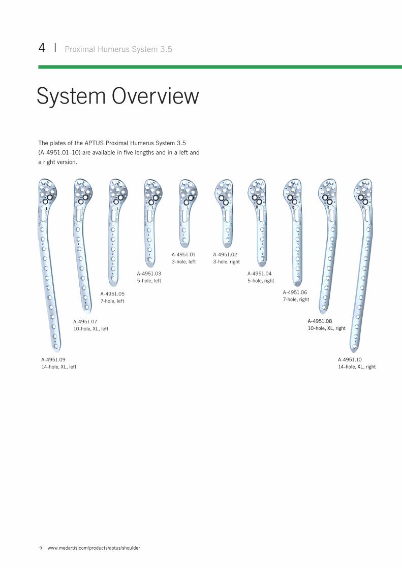
The plates of the APTUS Proximal Humerus System 3.5
(A-4951.01–10) are available in five lengths and in a left and
a right version.
A-4951.013-hole, left
A-4951.02 3-hole, right
A-4951.03 5-hole, left
A-4951.04 5-hole, right
A-4951.06 7-hole, right
A-4951.1014-hole, XL, right
A-4951.07 10-hole, XL, left
A-4951.09 14-hole, XL, left
A-4951.0810-hole, XL, right
A-4951.05 7-hole, left
A-4951.21Spiral blade 50° left
A-4951.22Spiral blade 50° right
A-4951.23Spiral blade 40° left
A-4951.24Spiral blade 40° right
A-4951.30 Screw for spiral blade
Proximal Humerus System 3.5 | 5
www.medartis.com/products/aptus/shoulder
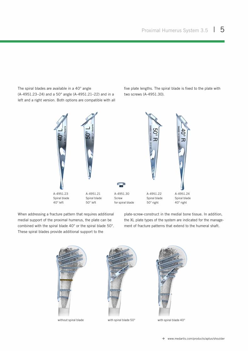
The spiral blades are available in a 40° angle
(A-4951.23–24) and a 50° angle (A-4951.21–22) and in a
left and a right version. Both options are compatible with all
five plate lengths. The spiral blade is fixed to the plate with
two screws (A-4951.30).
without spiral blade with spiral blade 50° with spiral blade 40°
When addressing a fracture pattern that requires additional
medial support of the proximal humerus, the plate can be
combined with the spiral blade 40° or the spiral blade 50°.
These spiral blades provide additional support to the
plate-screw-construct in the medial bone tissue. In addition,
the XL plate types of the system are indicated for the manage-
ment of fracture patterns that extend to the humeral shaft.
6 | Proximal Humerus System 3.5
www.medartis.com/products/aptus/shoulder
Instrument ApplicationGeneral Instrument Application
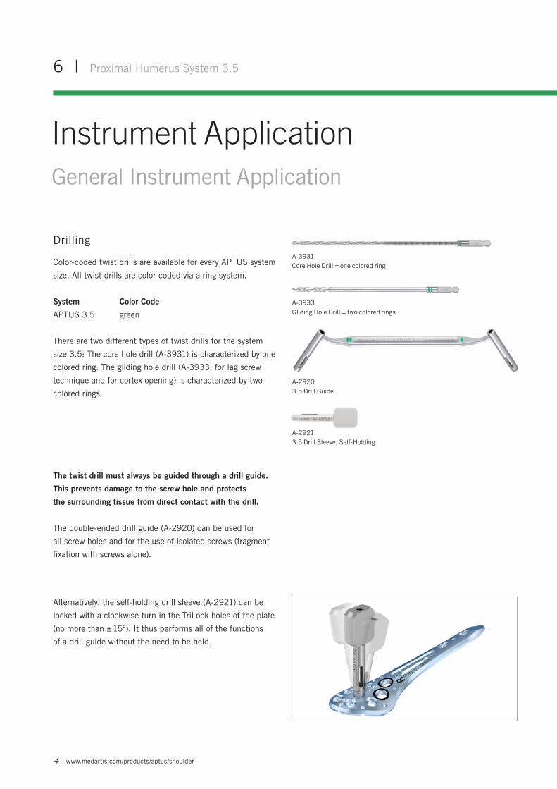
A-29213.5 Drill Sleeve, Self-Holding
A-3933Gliding Hole Drill = two colored rings
A-3931Core Hole Drill = one colored ring
A-2920 3.5 Drill Guide
The twist drill must always be guided through a drill guide.
This prevents damage to the screw hole and protects
the surrounding tissue from direct contact with the drill.
The double-ended drill guide (A-2920) can be used for
all screw holes and for the use of isolated screws (fragment
fixation with screws alone).
Drilling
Color-coded twist drills are available for every APTUS system
size. All twist drills are color-coded via a ring system.
System Color Code
APTUS 3.5 green
There are two different types of twist drills for the system
size 3.5: The core hole drill (A-3931) is characterized by one
colored ring. The gliding hole drill (A-3933, for lag screw
technique and for cortex opening) is characterized by two
colored rings.
Alternatively, the self-holding drill sleeve (A-2921) can be
locked with a clockwise turn in the TriLock holes of the plate
(no more than ± 15°). It thus performs all of the functions
of a drill guide without the need to be held.
Proximal Humerus System 3.5 | 7
www.medartis.com/products/aptus/shoulder
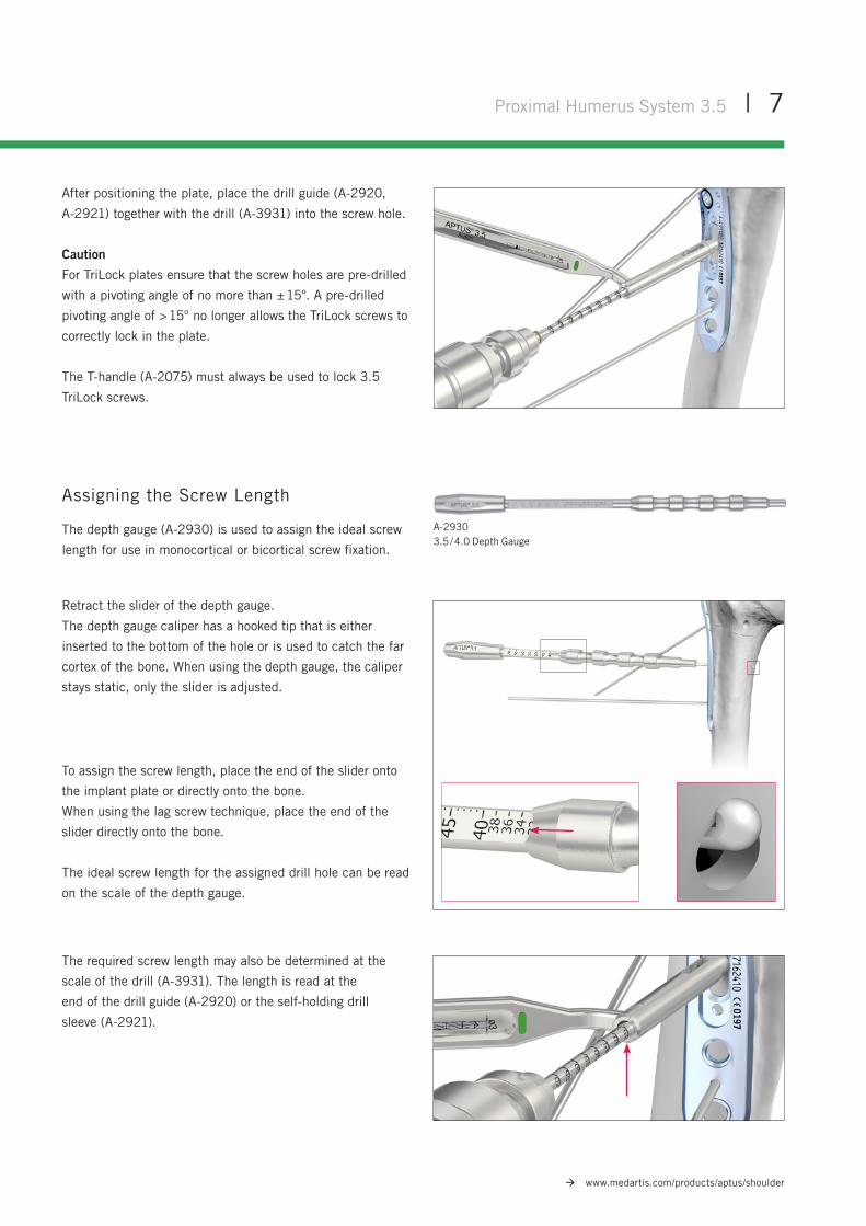
After positioning the plate, place the drill guide (A-2920,
A-2921) together with the drill (A-3931) into the screw hole.
Caution
For TriLock plates ensure that the screw holes are pre-drilled
with a pivoting angle of no more than ± 15°. A pre-drilled
pivoting angle of > 15° no longer allows the TriLock screws to
correctly lock in the plate.
The T-handle (A-2075) must always be used to lock 3.5
TriLock screws.
Assigning the Screw Length
The depth gauge (A-2930) is used to assign the ideal screw
length for use in monocortical or bicortical screw fixation.
A-29303.5 / 4.0 Depth Gauge
Retract the slider of the depth gauge.
The depth gauge caliper has a hooked tip that is either
inserted to the bottom of the hole or is used to catch the far
cortex of the bone. When using the depth gauge, the caliper
stays static, only the slider is adjusted.
To assign the screw length, place the end of the slider onto
the implant plate or directly onto the bone.
When using the lag screw technique, place the end of the
slider directly onto the bone.
The ideal screw length for the assigned drill hole can be read
on the scale of the depth gauge.
The required screw length may also be determined at the
scale of the drill (A-3931). The length is read at the
end of the drill guide (A-2920) or the self-holding drill
sleeve (A-2921).
8 | Proximal Humerus System 3.5
www.medartis.com/products/aptus/shoulder
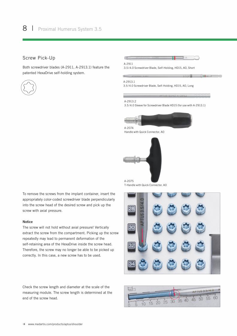
To remove the screws from the implant container, insert the
appropriately color-coded screwdriver blade perpendicularly
into the screw head of the desired screw and pick up the
screw with axial pressure.
Notice
The screw will not hold without axial pressure! Vertically
extract the screw from the compartment. Picking up the screw
repeatedly may lead to permanent deformation of the
self-retaining area of the HexaDrive inside the screw head.
Therefore, the screw may no longer be able to be picked up
correctly. In this case, a new screw has to be used.
Check the screw length and diameter at the scale of the
measuring module. The screw length is determined at the
end of the screw head.
Screw Pick-Up
Both screwdriver blades (A-2911, A-2913.1) feature the
patented HexaDrive self-holding system.
A-2074Handle with Quick Connector, AO
A-2075T-Handle with Quick Connector, AO
A-2911 3.5 / 4.0 Screwdriver Blade, Self-Holding, HD15, AO, Short
A-2913.13.5 / 4.0 Screwdriver Blade, Self-Holding, HD15, AO, Long
A-2913.23.5 / 4.0 Sleeve for Screwdriver Blade HD15 (for use with A-2913.1)
Proximal Humerus System 3.5 | 9
www.medartis.com/products/aptus/shoulder
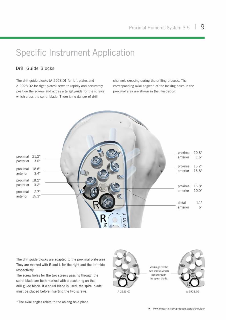
The drill guide blocks (A-2923.01 for left plates and
A-2923.02 for right plates) serve to rapidly and accurately
position the screws and act as a target guide for the screws
which cross the spiral blade. There is no danger of drill
channels crossing during the drilling process. The
corresponding axial angles * of the locking holes in the
proximal area are shown in the illustration.
Markings for the two screws which
pass through the spiral blade.
A-2923.01 A-2923.02
The drill guide blocks are adapted to the proximal plate area.
They are marked with R and L for the right and the left side
respectively.
The screw holes for the two screws passing through the
spiral blade are both marked with a black ring on the
drill guide block. If a spiral blade is used, the spiral blade
must be placed before inserting the two screws.
* The axial angles relate to the oblong hole plane.
Specific Instrument Application
Drill Guide Blocks
proximal 20.8°anterior 1.6°proximal 21.2°
posterior 3.0°
proximal 18.6°anterior 3.4°
proximal 18.2°posterior 3.2°
proximal 2.7°anterior 15.3°
proximal 16.2°anterior 13.8°
proximal 16.8°anterior 10.0°
distal 1.1°anterior 6°
10 | Proximal Humerus System 3.5
www.medartis.com/products/aptus/shoulder
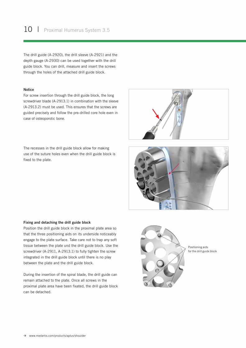
The recesses in the drill guide block allow for making
use of the suture holes even when the drill guide block is
fixed to the plate.
Fixing and detaching the drill guide block
Position the drill guide block in the proximal plate area so
that the three positioning aids on its underside noticeably
engage to the plate surface. Take care not to trap any soft
tissue between the plate und the drill guide block. Use the
screwdriver (A-2911, A-2913.1) to fully tighten the screw
integrated in the drill guide block until there is no play
between the plate and the drill guide block.
During the insertion of the spiral blade, the drill guide can
remain attached to the plate. Once all screws in the
proximal plate area have been fixated, the drill guide block
can be detached.
The drill guide (A-2920), the drill sleeve (A-2921) and the
depth gauge (A-2930) can be used together with the drill
guide block. You can drill, measure and insert the screws
through the holes of the attached drill guide block.
Notice
For screw insertion through the drill guide block, the long
screwdriver blade (A-2913.1) in combination with the sleeve
(A-2913.2) must be used. This ensures that the screws are
guided precisely and follow the pre-drilled core hole even in
case of osteoporotic bone.
Positioning aids for the drill guide block
Proximal Humerus System 3.5 | 11
www.medartis.com/products/aptus/shoulder
Positioning aids for the drill guide block
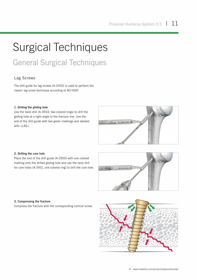
Lag Screws
The drill guide for lag screws (A-2920) is used to perform the
classic lag screw technique according to AO / ASIF.
1. Drilling the gliding hole
Use the twist drill (A-3933, two colored rings) to drill the
gliding hole at a right angle to the fracture line. Use the
end of the drill guide with two green markings and labeled
with «LAG».
2. Drilling the core hole
Place the end of the drill guide (A-2920) with one colored
marking onto the drilled gliding hole and use the twist drill
for core holes (A-3931, one colored ring) to drill the core hole.
3. Compressing the fracture
Compress the fracture with the corresponding cortical screw.
Surgical TechniquesGeneral Surgical Techniques
12 | Proximal Humerus System 3.5
www.medartis.com/products/aptus/shoulder
Specific Surgical Techniques
Proximal Humeral Plate without Spiral Blade
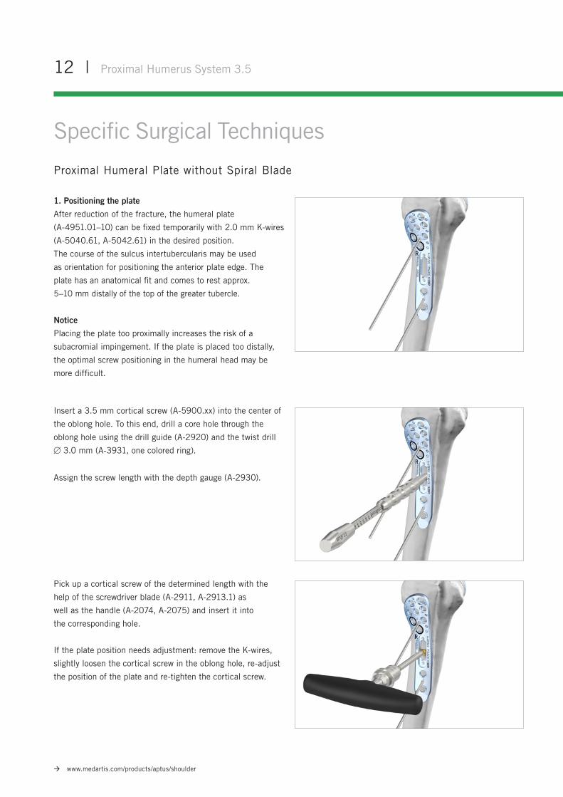
1. Positioning the plate
After reduction of the fracture, the humeral plate
(A-4951.01–10) can be fixed temporarily with 2.0 mm K-wires
(A-5040.61, A-5042.61) in the desired position.
The course of the sulcus intertubercularis may be used
as orientation for positioning the anterior plate edge. The
plate has an anatomical fit and comes to rest approx.
5–10 mm distally of the top of the greater tubercle.
Notice
Placing the plate too proximally increases the risk of a
subacromial impingement. If the plate is placed too distally,
the optimal screw positioning in the humeral head may be
more difficult.
Insert a 3.5 mm cortical screw (A-5900.xx) into the center of
the oblong hole. To this end, drill a core hole through the
oblong hole using the drill guide (A-2920) and the twist drill
3.0 mm (A-3931, one colored ring).
Assign the screw length with the depth gauge (A-2930).
Pick up a cortical screw of the determined length with the
help of the screwdriver blade (A-2911, A-2913.1) as
well as the handle (A-2074, A-2075) and insert it into
the corresponding hole.
If the plate position needs adjustment: remove the K-wires,
slightly loosen the cortical screw in the oblong hole, re-adjust
the position of the plate and re-tighten the cortical screw.
Proximal Humerus System 3.5 | 13
www.medartis.com/products/aptus/shoulder
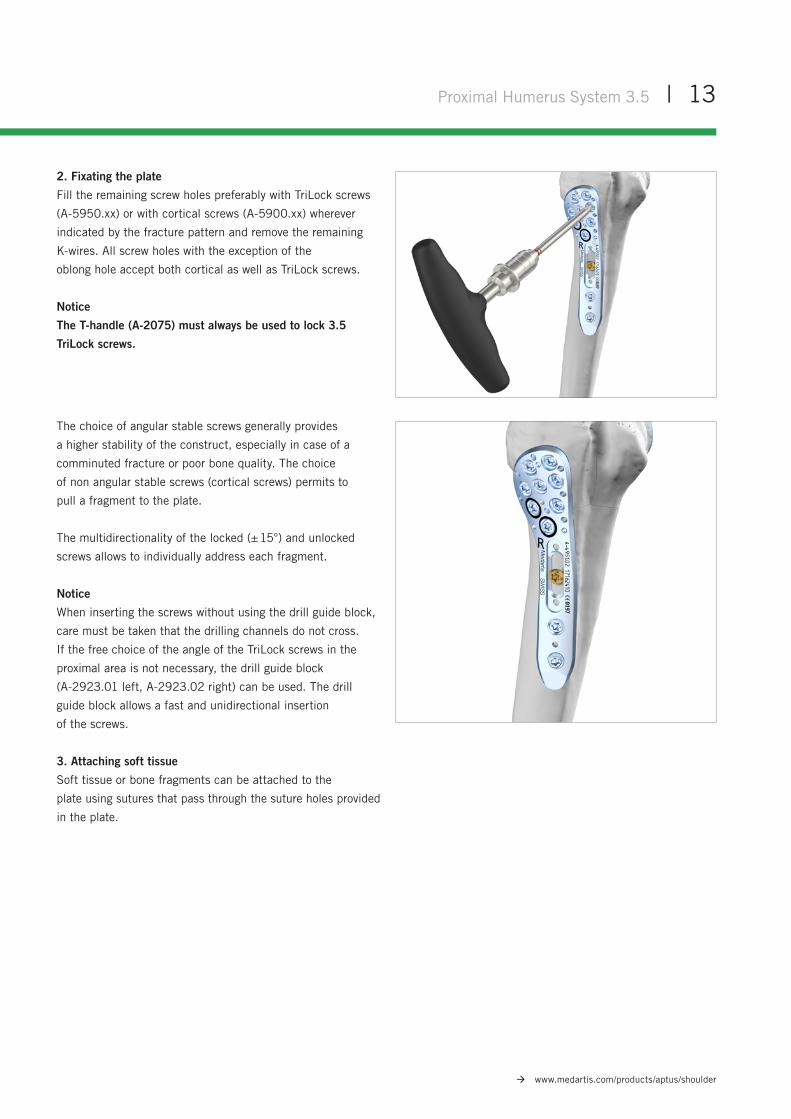
2. Fixating the plate
Fill the remaining screw holes preferably with TriLock screws
(A-5950.xx) or with cortical screws (A-5900.xx) wherever
indicated by the fracture pattern and remove the remaining
K-wires. All screw holes with the exception of the
oblong hole accept both cortical as well as TriLock screws.
Notice
The T-handle (A-2075) must always be used to lock 3.5
TriLock screws.
The choice of angular stable screws generally provides
a higher stability of the construct, especially in case of a
comminuted fracture or poor bone quality. The choice
of non angular stable screws (cortical screws) permits to
pull a fragment to the plate.
The multidirectionality of the locked (± 15°) and unlocked
screws allows to individually address each fragment.
Notice
When inserting the screws without using the drill guide block,
care must be taken that the drilling channels do not cross.
If the free choice of the angle of the TriLock screws in the
proximal area is not necessary, the drill guide block
(A-2923.01 left, A-2923.02 right) can be used. The drill
guide block allows a fast and unidirectional insertion
of the screws.
3. Attaching soft tissue
Soft tissue or bone fragments can be attached to the
plate using sutures that pass through the suture holes provided
in the plate.
14 | Proximal Humerus System 3.5
www.medartis.com/products/aptus/shoulder
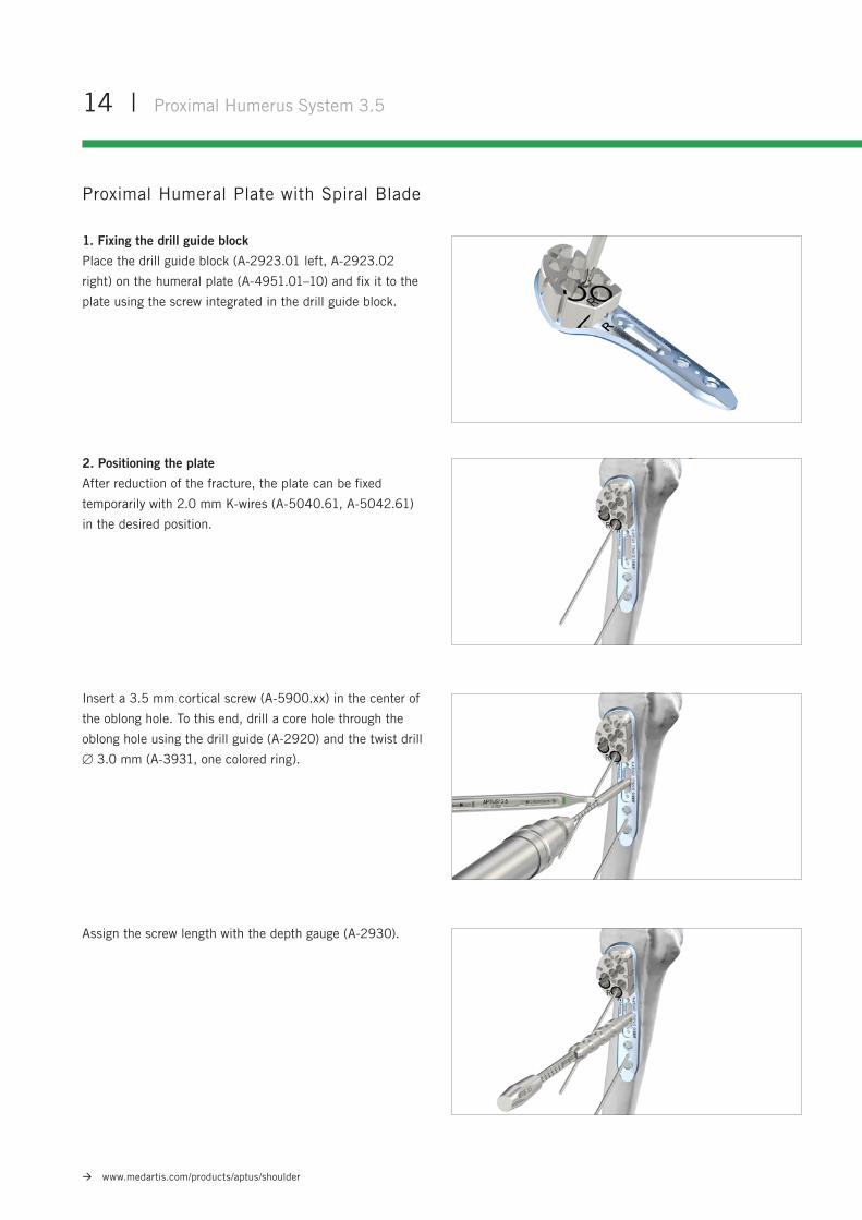
Insert a 3.5 mm cortical screw (A-5900.xx) in the center of
the oblong hole. To this end, drill a core hole through the
oblong hole using the drill guide (A-2920) and the twist drill
3.0 mm (A-3931, one colored ring).
2. Positioning the plate
After reduction of the fracture, the plate can be fixed
temporarily with 2.0 mm K-wires (A-5040.61, A-5042.61)
in the desired position.
1. Fixing the drill guide block
Place the drill guide block (A-2923.01 left, A-2923.02
right) on the humeral plate (A-4951.01–10) and fix it to the
plate using the screw integrated in the drill guide block.
Proximal Humeral Plate with Spiral Blade
Assign the screw length with the depth gauge (A-2930).
Proximal Humerus System 3.5 | 15
www.medartis.com/products/aptus/shoulder
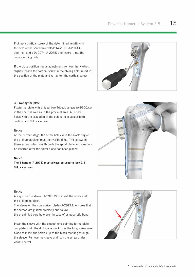
Pick up a cortical screw of the determined length with
the help of the screwdriver blade (A-2911, A-2913.1)
and the handle (A-2074, A-2075) and insert it into the
corresponding hole.
If the plate position needs adjustment: remove the K-wires,
slightly loosen the cortical screw in the oblong hole, re-adjust
the position of the plate and re-tighten the cortical screw.
3. Fixating the plate
Fixate the plate with at least two TriLock screws (A-5950.xx)
in the shaft as well as in the proximal area. All screw
holes with the exception of the oblong hole accept both
cortical and TriLock screws.
Notice
At the current stage, the screw holes with the black ring on
the drill guide block must not yet be filled. The screws in
these screw holes pass through the spiral blade and can only
be inserted after the spiral blade has been placed.
Notice
The T-handle (A-2075) must always be used to lock 3.5
TriLock screws.
Notice
Always use the sleeve (A-2913.2) to insert the screws into
the drill guide block.
The sleeve on the screwdriver blade (A-2913.1) ensures that
the screws are guided precisely and follow
the pre-drilled core hole even in case of osteoporotic bone.
Insert the sleeve with the smooth end pointing to the plate
completely into the drill guide block. Use the long screwdriver
blade to insert the screws up to the black marking through
the sleeve. Remove the sleeve and lock the screw under
visual control.
16 | Proximal Humerus System 3.5
www.medartis.com/products/aptus/shoulder
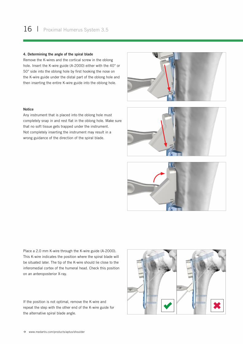
4. Determining the angle of the spiral blade
Remove the K-wires and the cortical screw in the oblong
hole. Insert the K-wire guide (A-2000) either with the 40° or
50° side into the oblong hole by first hooking the nose on
the K-wire guide under the distal part of the oblong hole and
then inserting the entire K-wire guide into the oblong hole.
Notice
Any instrument that is placed into the oblong hole must
completely snap in and rest flat in the oblong hole. Make sure
that no soft tissue gets trapped under the instrument.
Not completely inserting the instrument may result in a
wrong guidance of the direction of the spiral blade.
If the position is not optimal, remove the K-wire and
repeat the step with the other end of the K-wire guide for
the alternative spiral blade angle.
Place a 2.0 mm K-wire through the K-wire guide (A-2000).
This K-wire indicates the position where the spiral blade will
be situated later. The tip of the K-wire should lie close to the
inferomedial cortex of the humeral head. Check this position
on an anteroposterior X-ray.
Proximal Humerus System 3.5 | 17
www.medartis.com/products/aptus/shoulder
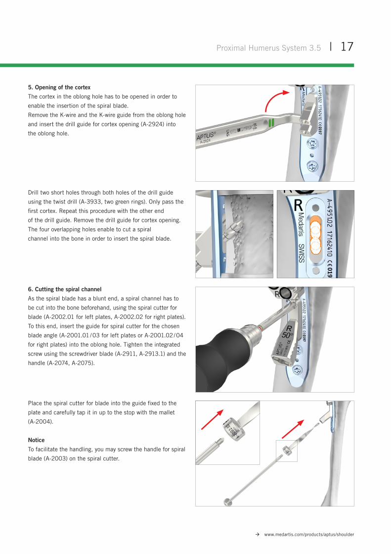
5. Opening of the cortex
The cortex in the oblong hole has to be opened in order to
enable the insertion of the spiral blade.
Remove the K-wire and the K-wire guide from the oblong hole
and insert the drill guide for cortex opening (A-2924) into
the oblong hole.
6. Cutting the spiral channel
As the spiral blade has a blunt end, a spiral channel has to
be cut into the bone beforehand, using the spiral cutter for
blade (A-2002.01 for left plates, A-2002.02 for right plates).
To this end, insert the guide for spiral cutter for the chosen
blade angle (A-2001.01 / 03 for left plates or A-2001.02 / 04
for right plates) into the oblong hole. Tighten the integrated
screw using the screwdriver blade (A-2911, A-2913.1) and the
handle (A-2074, A-2075).
Drill two short holes through both holes of the drill guide
using the twist drill (A-3933, two green rings). Only pass the
first cortex. Repeat this procedure with the other end
of the drill guide. Remove the drill guide for cortex opening.
The four overlapping holes enable to cut a spiral
channel into the bone in order to insert the spiral blade.
Place the spiral cutter for blade into the guide fixed to the
plate and carefully tap it in up to the stop with the mallet
(A-2004).
Notice
To facilitate the handling, you may screw the handle for spiral
blade (A-2003) on the spiral cutter.
18 | Proximal Humerus System 3.5
www.medartis.com/products/aptus/shoulder
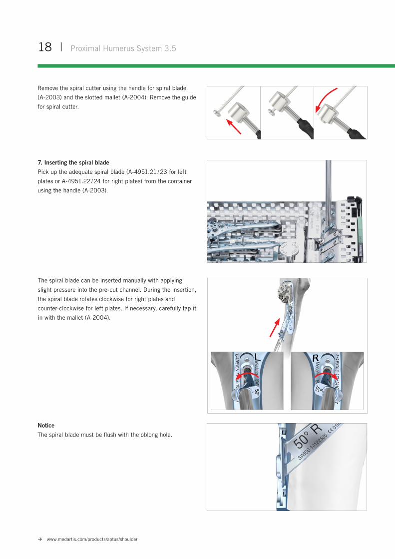
Notice
The spiral blade must be flush with the oblong hole.
The spiral blade can be inserted manually with applying
slight pressure into the pre-cut channel. During the insertion,
the spiral blade rotates clockwise for right plates and
counter-clockwise for left plates. If necessary, carefully tap it
in with the mallet (A-2004).
7. Inserting the spiral blade
Pick up the adequate spiral blade (A-4951.21 / 23 for left
plates or A-4951.22 / 24 for right plates) from the container
using the handle (A-2003).
Remove the spiral cutter using the handle for spiral blade
(A-2003) and the slotted mallet (A-2004). Remove the guide
for spiral cutter.
Proximal Humerus System 3.5 | 19
www.medartis.com/products/aptus/shoulder
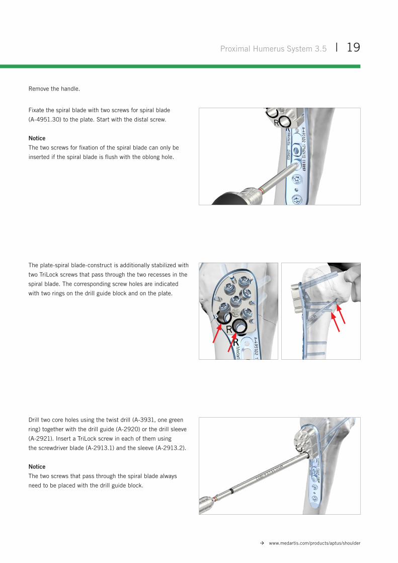
Fixate the spiral blade with two screws for spiral blade
(A-4951.30) to the plate. Start with the distal screw.
Notice
The two screws for fixation of the spiral blade can only be
inserted if the spiral blade is flush with the oblong hole.
Remove the handle.
Drill two core holes using the twist drill (A-3931, one green
ring) together with the drill guide (A-2920) or the drill sleeve
(A-2921). Insert a TriLock screw in each of them using
the screwdriver blade (A-2913.1) and the sleeve (A-2913.2).
Notice
The two screws that pass through the spiral blade always
need to be placed with the drill guide block.
The plate-spiral blade-construct is additionally stabilized with
two TriLock screws that pass through the two recesses in the
spiral blade. The corresponding screw holes are indicated
with two rings on the drill guide block and on the plate.
20 | Proximal Humerus System 3.5
www.medartis.com/products/aptus/shoulder
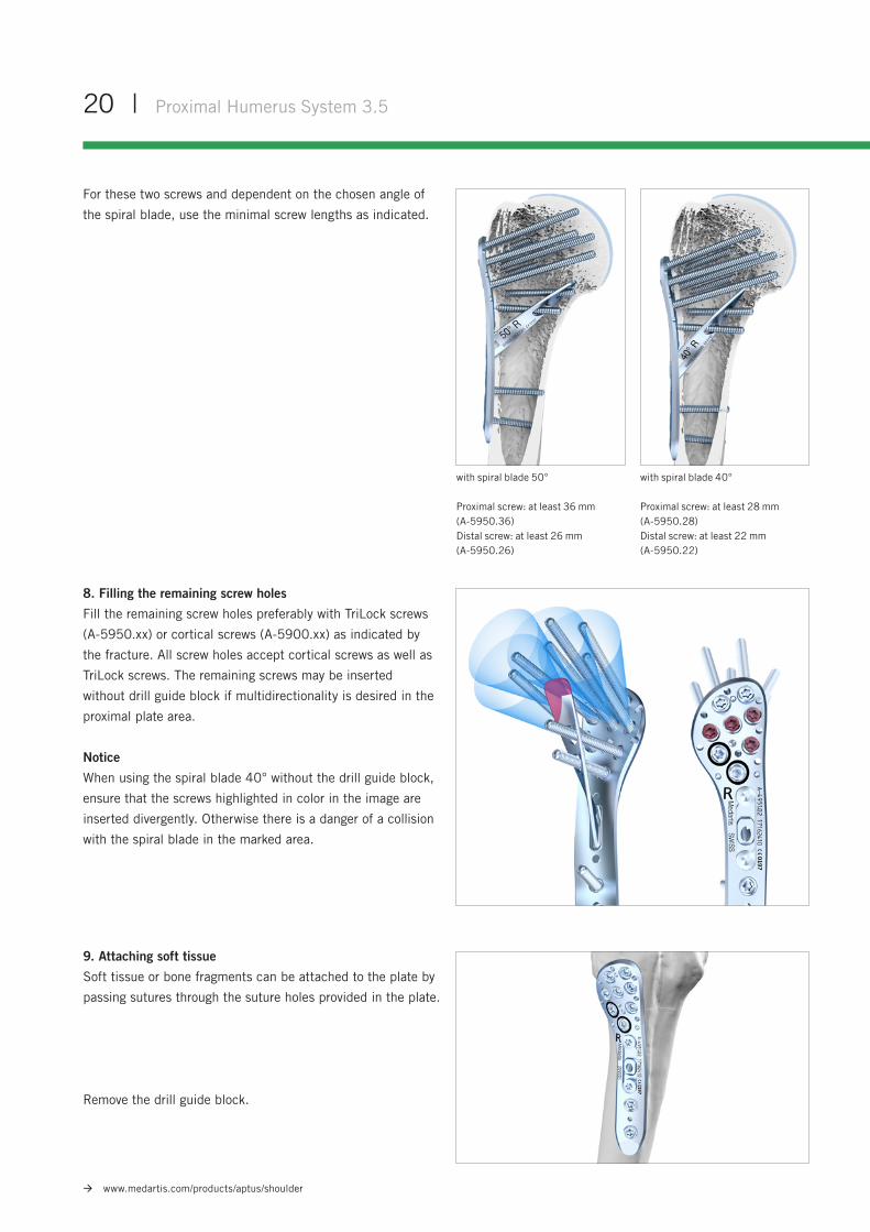
For these two screws and dependent on the chosen angle of
the spiral blade, use the minimal screw lengths as indicated.
with spiral blade 40°
Proximal screw: at least 28 mm (A-5950.28)Distal screw: at least 22 mm(A-5950.22)
with spiral blade 50°
Proximal screw: at least 36 mm (A-5950.36)Distal screw: at least 26 mm (A-5950.26)
8. Filling the remaining screw holes
Fill the remaining screw holes preferably with TriLock screws
(A-5950.xx) or cortical screws (A-5900.xx) as indicated by
the fracture. All screw holes accept cortical screws as well as
TriLock screws. The remaining screws may be inserted
without drill guide block if multidirectionality is desired in the
proximal plate area.
Notice
When using the spiral blade 40° without the drill guide block,
ensure that the screws highlighted in color in the image are
inserted divergently. Otherwise there is a danger of a collision
with the spiral blade in the marked area.
9. Attaching soft tissue
Soft tissue or bone fragments can be attached to the plate by
passing sutures through the suture holes provided in the plate.
Remove the drill guide block.
Proximal Humerus System 3.5 | 21
www.medartis.com/products/aptus/shoulder
Explantation
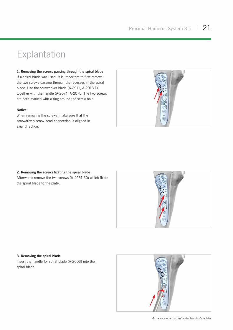
1. Removing the screws passing through the spiral blade
If a spiral blade was used, it is important to first remove
the two screws passing through the recesses in the spiral
blade. Use the screwdriver blade (A-2911, A-2913.1)
together with the handle (A-2074, A-2075. The two screws
are both marked with a ring around the screw hole.
Notice
When removing the screws, make sure that the
screwdriver / screw head connection is aligned in
axial direction.
2. Removing the screws fixating the spiral blade
Afterwards remove the two screws (A-4951.30) which fixate
the spiral blade to the plate.
3. Removing the spiral blade
Insert the handle for spiral blade (A-2003) into the
spiral blade.
22 | Proximal Humerus System 3.5
www.medartis.com/products/aptus/shoulder
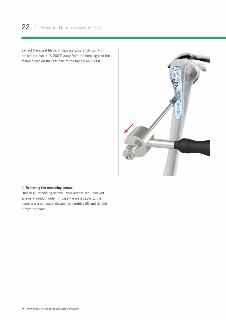
4. Removing the remaining screws
Unlock all remaining screws. Now remove the unlocked
screws in random order. In case the plate sticks to the
bone, use a periosteal elevator to carefully lift and detach
it from the bone.
Extract the spiral blade. If necessary, carefully tap with
the slotted mallet (A-2004) away from the bone against the
metallic disc on the rear part of the handle (A-2003).
Einlauf- phase
B
Vor-schanzen
AFreilauf
CVerblockung
D
Drehwinkel α
Verblockungs-Drehmoment MLock
Dre
hmom
ent M
Einlauf-Drehmoment («Schanzen») MIn
«Vorschanzen» MVs
Proximal Humerus System 3.5 | 23
www.medartis.com/products/aptus/shoulder
TriLock® Locking Technology
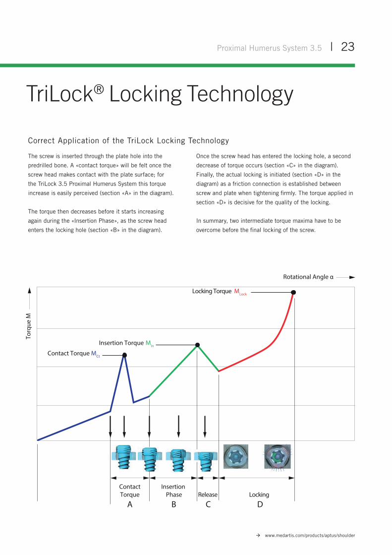
Correct Application of the TriLock Locking Technology
The screw is inserted through the plate hole into the
predrilled bone. A «contact torque» will be felt once the
screw head makes contact with the plate surface; for
the TriLock 3.5 Proximal Humerus System this torque
increase is easily perceived (section «A» in the diagram).
The torque then decreases before it starts increasing
again during the «Insertion Phase», as the screw head
enters the locking hole (section «B» in the diagram).
Once the screw head has entered the locking hole, a second
decrease of torque occurs (section «C» in the diagram).
Finally, the actual locking is initiated (section «D» in the
diagram) as a friction connection is established between
screw and plate when tightening firmly. The torque applied in
section «D» is decisive for the quality of the locking.
In summary, two intermediate torque maxima have to be
overcome before the final locking of the screw.
InsertionPhase
B
ContactTorque
ARelease
CLocking
D
Rotational Angle α
Locking Torque MLock
Torq
ue M
Insertion Torque MIn
Contact Torque MCt
24 | Proximal Humerus System 3.5
www.medartis.com/products/aptus/shoulder
Correct Locking (± 15°) of the TriLock Screws in the APTUS Proximal Humerus System 3.5
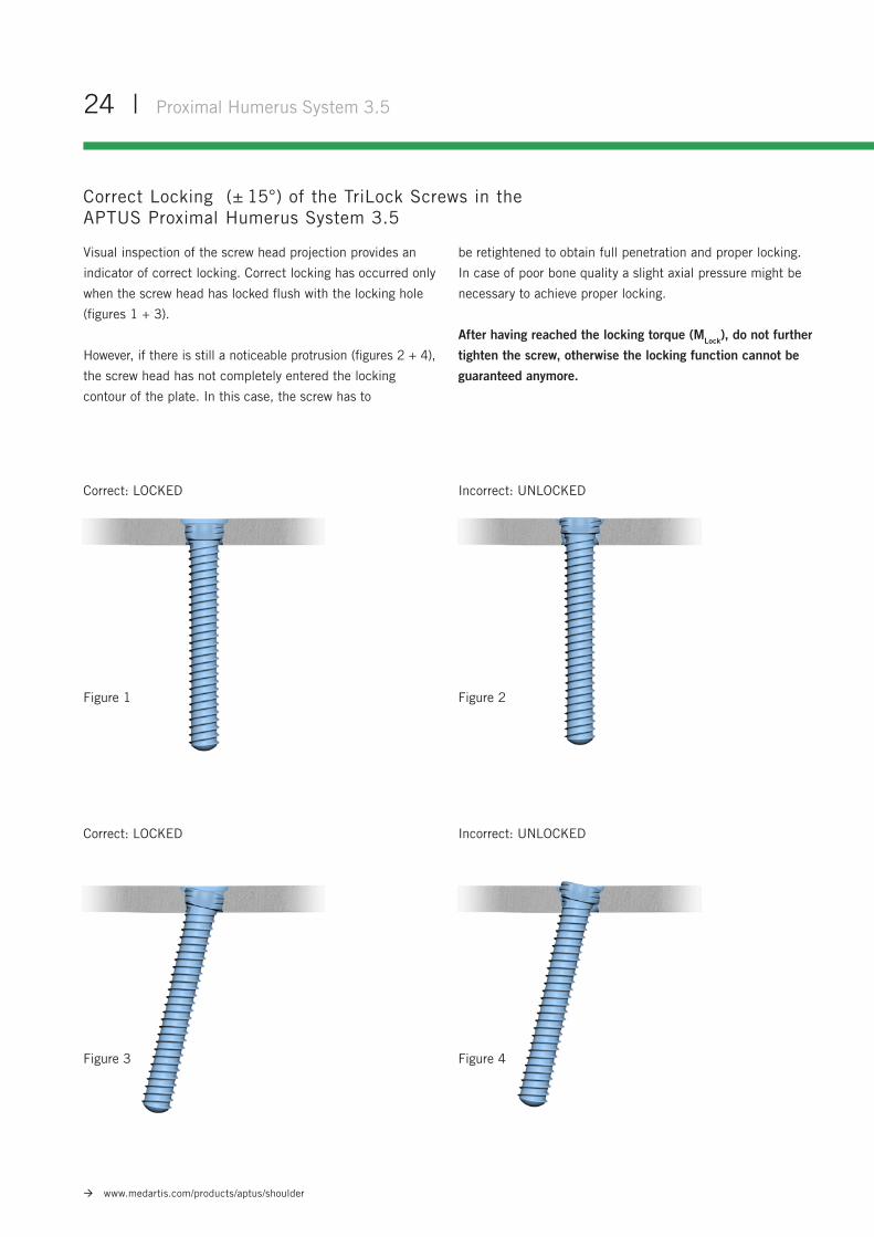
Visual inspection of the screw head projection provides an
indicator of correct locking. Correct locking has occurred only
when the screw head has locked flush with the locking hole
(figures 1 + 3).
However, if there is still a noticeable protrusion (figures 2 + 4),
the screw head has not completely entered the locking
contour of the plate. In this case, the screw has to
be retightened to obtain full penetration and proper locking.
In case of poor bone quality a slight axial pressure might be
necessary to achieve proper locking.
After having reached the locking torque (MLock), do not further
tighten the screw, otherwise the locking function cannot be
guaranteed anymore.
Correct: LOCKED
Correct: LOCKED
Incorrect: UNLOCKED
Incorrect: UNLOCKED
Figure 1
Figure 3
Figure 2
Figure 4
Proximal Humerus System 3.5 | 25
www.medartis.com/products/aptus/shoulder
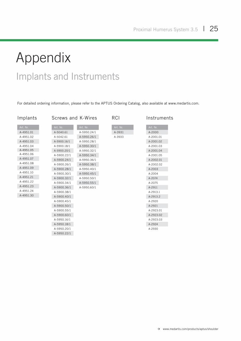
AppendixImplants and Instruments
For detailed ordering information, please refer to the APTUS Ordering Catalog, also available at www.medartis.com.
Implants RCI InstrumentsScrews and K-Wires
Art. Nr.
A-4951.01
A-4951.02
A-4951.03
A-4951.04A-4951.05A-4951.06
A-4951.07
A-4951.08
A-4951.09
A-4951.10
A-4951.21
A-4951.22
A-4951.23
A-4951.24
A-4951.30
Art. Nr.
A-3931
A-3933
Art. Nr.
A-2000
A-2001.01
A-2001.02
A-2001.03
A-2001.04
A-2001.05
A-2002.01
A-2002.02
A-2003
A-2004
A-2074
A-2075
A-2911
A-2913.1
A-2913.2
A-2920
A-2921
A-2923.01
A-2923.02
A-2923.03
A-2924
A-2930
Art. Nr.
A-5040.61
A-5042.61
A-5900.16/1
A-5900.18/1
A-5900.20/1
A-5900.22/1
A-5900.24/1
A-5900.26/1
A-5900.28/1
A-5900.30/1
A-5900.32/1
A-5900.34/1
A-5900.36/1
A-5900.38/1
A-5900.40/1
A-5900.45/1
A-5900.50/1
A-5900.55/1
A-5900.60/1
A-5950.16/1
A-5950.18/1
A-5950.20/1
A-5950.22/1
Art. Nr.
A-5950.24/1
A-5950.26/1
A-5950.28/1
A-5950.30/1
A-5950.32/1
A-5950.34/1
A-5950.36/1
A-5950.38/1
A-5950.40/1
A-5950.45/1
A-5950.50/1
A-5950.55/1
A-5950.60/1

SHOULDER-01010001_v5 / © 2018-10, Medartis AG, Switzerland. All technical data subject to alteration.
MANUFACTURER & HEADQUARTERS
Medartis AG | Hochbergerstrasse 60E | 4057 Basel / Switzerland
P +41 61 633 34 34 | F +41 61 633 34 00 | www.medartis.com
SUBSIDIARIES
Australia | Brazil | Germany | France | Mexico | New Zealand | Austria | Poland | UK | USA
For detailed information regarding our subsidiaries and distributors, please visit www.medartis.com
Disclaimer: This information is intended to demonstrate the Medartis portfolio of medical devices. A surgeon must always rely on her or his own professional clinical judgement when deciding whether to use a particular product when treating a particular patient. Medartis is not giving any medical advice. The devices may not be available in all countries due to registration and / or medical practices. For further questions, please contact your Medartis representative (www.medartis.com). This information contains CE-marked products.For US only: Federal law restricts this device to sale by or on the order of a physician.