Embed Size (px)
Citation preview
AP30-1
APPENDIX 30 (REV.WRC-15)*
Provisions for all services and associated Plans and List1 for the broadcasting-satellite service in the frequency bands 11.7-12.2 GHz (in Region 3), 11.7-12.5 GHz (in Region 1)
and 12.2-12.7 GHz (in Region 2) (WRC-03)
(See Articles 9 and 11) (WRC-03)
TABLE OF CONTENTS
Page
Article 1 General definitions ........................................................................................... 3
Article 2 Frequency bands ............................................................................................... 4
Article 2A Use of the guardbands ...................................................................................... 4
Article 3 Execution of the provisions and associated Plans ............................................ 5
Article 4 Procedures for modifications to the Region 2 Plan or for additional uses in Regions 1 and 3 ................................................................................................ 6
Article 5 Notification, examination and recording in the Master International Frequency Register of frequency assignments to space stations in the broadcasting-satellite service ........................................................................... 18
Article 6 Coordination, notification and recording in the Master International Frequency Register of frequency assignments to terrestrial stations or to earth stations in the fixed-satellite service (Earth-to-space) affecting frequencyassignments to broadcasting-satellite stations in the bands 11.7-12.2 GHz(in Region 3), 11.7-12.5 GHz (in Region 1) and 12.2-12.7 GHz (in Region 2).......................................................................................................................... 23
Article 7 Coordination, notification and recording in the Master International Frequency Register of frequency assignments to stations in the fixed-satellite service (space-to-Earth) in the bands 11.7-12.2 GHz (in Region 2), 12.2-12.7 GHz (in Region 3) and 12.5-12.7 GHz (in Region 1), and to stations in the broadcasting-satellite service in the band 12.5-12.7 GHz (in Region 3) when frequency assignments to broadcasting-satellite stations in the bands 11.7-12.5 GHz in Region 1, 12.2-12.7 GHz in Region 2 and 11.7-12.2 GHz in Region 3 are involved .................................................................................. 24
_______________*to refer to a frequency assignment associated with a given orbital position. See also Annex 7 for the orbital limitations. (WRC-2000)
1 The Regions 1 and 3 List of additional uses is annexed to the Master International Frequency Register (see Resolution 542 (WRC-2000)**). (WRC-03)
** Note by the Secretariat: This Resolution was abrogated by WRC-03.
Note by the Secretariat: Reference to an Article with the number in roman is referring to an Article in this Appendix.
- 469 -
AP30-2
Page
Article 8 Miscellaneous provisions relating to the procedures ....................................... 25
Article 9 (SUP - WRC-03)
Article 10 The Plan for the broadcasting-satellite service in the frequency band 12.2-12.7 GHz in Region 2 .............................................................................. 26
Article 11 Plan for the broadcasting-satellite service in the frequency bands 11.7-12.2 GHz in Region 3 and 11.7-12.5 GHz in Region 1 ........................... 65
Article 12 Relationship to Resolution 507 (REV.WRC-03)* ........................................... 88
Article 13 Interference ....................................................................................................... 88
Article 14 Period of validity of the provisions and associated Plans ................................ 88
ANNEXES
Annex 1 Limits for determining whether a service of an administration is affected by a proposed modification to the Region 2 Plan or by a proposed new or modified assignment in the Regions 1 and 3 List or when it is necessary under this Appendix to seek the agreement of any other administration ................... 89
Annex 2 Basic characteristics to be furnished in notices relating to space stations in the broadcasting-satellite service ........................................................................... 94
Annex 3 Method for determining the limiting interfering power flux-density at the edge of a broadcasting-satellite service area in the frequency bands 11.7-12.2 GHz (in Region 3), 11.7-12.5 GHz (in Region 1) and 12.2-12.7 GHz (in Region 2) and for calculating the power flux-density produced in these bands by a terrestrial station, or by a transmitting earth station in the fixed-satellite service in the band 12.5-12.7 GHz ...................... 94
Annex 4 Need for coordination of a transmitting space station in the fixed-satellite service or in the broadcasting-satellite service where this service is not subject to a Plan: in Region 2 (11.7-12.2 GHz) with respect to the Plan, the List or proposed new or modified assignments in the List for Regions 1 and 3; in Region 1 (12.5-12.7 GHz) and in Region 3 (12.2-12.7 GHz) with respect to the Plan or proposed modifications to the Plan in Region 2; in Region 3 (12.2-12.5 GHz) with respect to the Plan, List or proposed new or modified assignments in the List for Region 1 ................................................................ 104
Annex 5 Technical data used in establishing the provisions and associated Plans andthe Regions 1 and 3 List, which should be used for their application .............. 106
Annex 6 Criteria for sharing between services ............................................................... 142
Annex 7 Orbital position limitations ............................................................................... 148
_______________* Note by the Secretariat: This Resolution was revised by WRC-12 and WRC-15.
- 470 -
AP30-3
ARTICLE 1 (REV.WRC-03)
General definitions
1 For the purposes of this Appendix, the following terms shall have the meanings defined below:
1.1 1977 Conference: World Administrative Radio Conference for the Planning of the Broadcasting-Satellite Service in the Frequency Bands 11.7-12.2 GHz (in Regions 2 and 3) and 11.7-12.5 GHz (in Region 1), called in short World Broadcasting-Satellite Administrative Radio Conference (Geneva, 1977) (WARC-77).
1.2 1983 Conference: Regional Administrative Radio Conference for the Planning in Region 2 of the Broadcasting-Satellite Service in the Frequency Band 12.2-12.7 GHz and Associated Feeder Links in the Frequency Band 17.3-17.8 GHz, called in short Regional Administrative Conference for the Planning of the Broadcasting-Satellite Service in Region 2 (Geneva, 1983) (RARC Sat-R2).
1.3 1985 Conference: First Session of the World Administrative Radio Conference on the Use of the Geostationary-Satellite Orbit and the Planning of Space Services Utilizing It (Geneva, 1985), called in short WARC Orb-85.
1.3A 1997 Conference: World Radiocommunication Conference (Geneva, 1997), called in short WRC-97.
1.3B 2000 Conference: World Radiocommunication Conference (Istanbul, 2000), called in short WRC-2000.
1.4 Regions 1 and 3 Plan: The Plan for the broadcasting-satellite service in the frequency bands 11.7-12.2 GHz in Region 3 and 11.7-12.5 GHz in Region 1 contained in this Appendix.
1.5 Region 2 Plan: The Plan for the broadcasting-satellite service in the frequency band 12.2-12.7 GHz in Region 2 contained in this Appendix, together with any modifications resulting from the successful application of the procedures of Article 4.
1.6 Frequency assignment in conformity with the Plan:
any frequency assignment which appears in the Regions 1 and 3 Plan; or
any frequency assignment which appears in the Region 2 Plan or for which the procedure of Article 4 has been successfully applied.
1.7 Additional use in Regions 1 and 3: For the application of the provisions of this Appendix, additional uses in Regions 1 and 3 are:
use of assignments with characteristics different from those appearing in the Regions 1 and 3 Plan and which are capable of causing more interference than the corresponding entries in the Plan;
use of assignments in addition to those appearing in the Plan.
- 471 -
AP30-4
1.8 Regions 1 and 3 List of ad : The List of assignments for additional uses in Regions 1 and 3 as established by WRC-2000 (see Resolution 542 (WRC-2000)*), as updated following the successful application of the procedure of § 4.1 of Article 4. (WRC-03)
1.9 Frequency assignment in conformity with the List: Any frequency assignment which appears in the List as updated following successful application of § 4.1 of Article 4. (WRC-03)
1.10 The broadcasting-satellite service subject to one of the Plans: The broadcasting-satellite service subject to one of the Plans referred to in this Appendix is the broadcasting-satellite service in the bands 11.7-12.5 GHz in Region 1, 12.2-12.7 GHz in Region 2 and 11.7-12.2 GHz in Region 3. (WRC-03)
ARTICLE 2 (WRC-03)
Frequency bands
2.1 The provisions of this Appendix apply to the broadcasting-satellite service in the frequency bands between 11.7 GHz and 12.2 GHz in Region 3, between 11.7 GHz and 12.5 GHz in Region 1 and between 12.2 GHz and 12.7 GHz in Region 2 and to the other services to which these bands are allocated in Regions 1, 2 and 3, insofar as their relationship to the broadcasting-satellite service in these bands is concerned.
2.2 (SUP - WRC-03)
ARTICLE 2A (REV.WRC-15)
Use of the guardbands
2A.1 The use of the guardbands defined in § 3.9 of Annex 5 to provide space operation functions in accordance with No. 1.23 in support of the operation of geostationary-satellite networks in the broadcasting-satellite service (BSS) is not subject to the application of Section I of Article 9.
2A.1.1 Coordination between assignments intended to provide the space operation functions and assignments of the BSS subject to a Plan shall be effected using the provisions of Article 7.
2A.1.2 Coordination among assignments intended to provide the space operation functions and services not subject to a Plan shall be effected using the provisions of Nos. 9.7, 9.17, 9.18 and the associated provisions of Section II of Article 9, or § 4.1.1 d) or 4.2.3 d) of Article 4, as appropriate.
_______________* Note by the Secretariat: This Resolution was abrogated by WRC-03.
- 472 -
AP30-5
2A.1.3 Coordination of modifications to the Region 2 Plan or assignments to be included in the Regions 1 and 3 List with assignments intended to provide these functions shall be effected using § 4.1.1 e) or 4.2.3 e), as appropriate, of Article 4.
2A.1.4 Requests for the coordination referred to in §2A.1.1, 2A.1.2 and 2A.1.3 shall be sent by the requesting administration to the Bureau, together with the appropriate information listed in Appendix 4.
2A.2 Any assignment intended to provide these functions in support of a geostationary-satellite network in the BSS shall be notified under Article 11 and brought into use within the following time-limits1bis: (WRC-15)
2A.2.1 a) for the case where the associated BSS assignments are contained in one of the initial Plans (Region 2 Plans incorporated in the Radio Regulations at WARC Orb-85 and the Regions 1 and 3 Plan adopted at WRC-2000), within the regulatory time-limit referred to in § 4.1.3 or § 4.2.6 of Article 4 from the date of receipt by the Bureau of the complete Appendix 4 data for those assignments intended to provide the space operation functions;
2A.2.2 b) for the case where the associated BSS assignments have been submitted under § 4.1.3 or § 4.2.6 of Article 4 for entry in the Regions 1 and 3 List or a modification to the Region 2Plan, within the regulatory time-limit referred to in § 4.1.3 or § 4.2.6 of Article 4 for those associated BSS assignments;
2A.2.3 c) for the case where the associated BSS assignments have already been brought into use in accordance with the Radio Regulations, within the regulatory time-limit referred to in § 4.1.3 and § 4.2.6 of Article 4 from the date of receipt by the Bureau of the complete Appendix 4 data for those assignments intended to provide the space operation functions.
2A.3 Section II of Article 23 does not apply to assignments in the guardbands intended to provide the above-mentioned functions.
ARTICLE 3 (WRC-2000)
Execution of the provisions and associated Plans
3.1 The Member States in Regions 1, 2 and 3 shall adopt, for their broadcasting-satellite space stations2 operating in the frequency bands referred to in this Appendix, the characteristics specified in the appropriate Regional Plan and the associated provisions.
3.2 The Member States shall not change the characteristics specified in the Regions 1 and 3Plan or in the Region 2 Plan, or bring into use assignments to broadcasting-satellite space stations or to stations in the other services to which these frequency bands are allocated, except as provided for in the Radio Regulations and the appropriate Articles and Annexes of this Appendix.
_______________1bis The time-limit is established at the time when the request is received under § 2A.1.4. (WRC-15)
2 Such stations may also be used for transmissions in the fixed-satellite service (space-to-Earth) in accordance with No. 5.492.
- 473 -
AP30-6
3.3 The Regions 1 and 3 Plan is based on national coverage from the geostationary-satellite orbit. The associated procedures contained in this Appendix are intended to promote long-term flexibility of the Plan and to avoid monopolization of the planned bands and orbit by a country or a group of countries.
ARTICLE 4 (REV.WRC-15)
Procedures for modifications to the Region 2 Plan or for additional uses in Regions 1 and 33
4.1 Provisions applicable to Regions 1 and 3
4.1.1 An administration proposing to include a new or modified assignment in the List shall seek the agreement of those administrations whose services are considered to be affected, i.e. administrations:
a) of Regions 1 and 3 having a frequency assignment to a space station in the broadcasting-satellite service which is included in the Regions 1 and 3 Plan with a necessary bandwidth, any portion of which falls within the necessary bandwidth of the proposed assignment; or
b) of Regions 1 and 3 having a frequency assignment included in the List or for which complete Appendix 4 information has been received by the Radiocommunication Bureau in accordance with the provisions of § 4.1.3, and any portion of which falls within the necessary bandwidth of the proposed assignment; or
c) of Region 2 having a frequency assignment to a space station in the broadcasting-satellite service which is in conformity with the Region 2 Plan, or in respect of which proposed modifications to that Plan have been received by the Bureau in accordance with the provisions of § 4.2.6 with a necessary bandwidth, any portion of which falls within the necessary bandwidth of the proposed assignment; or
d) having no frequency assignment in the broadcasting-satellite service with a necessary bandwidth, any portion of which falls within the necessary bandwidth of the proposed assignment, but in whose territory the power flux-density value exceeds the prescribed limit as a result of the proposed assignment, or having an assignment whose associated service area does not cover the whole of the territory of the administration, and in whose territory outside that service area the power flux-density from the proposed assignment exceeds the prescribed limit as a result of the proposed assignment; or
e) having a frequency assignment in the band 11.7-12.2 GHz in Region 2 or 12.2-12.5 GHzin Region 3 to a space station in the fixed-satellite service which is recorded in the Master International Frequency Register (Master Register) or for which complete coordination information has been received by the Bureau for coordination under No. 9.7, or under § 7.1 of Article 7.
_______________3 The provisions of Resolution 49 (Rev.WRC-15) apply. (WRC-15)
- 474 -
AP30-7
4.1.2 The services of an administration are considered to be affected when the limits shown in Annex 1 are exceeded.
4.1.3 An administration, or one4 acting on behalf of a group of named administrations, intending to include a new or modified assignment in the List shall send to the Bureau, not earlier than eight years but preferably not later than two years before the date on which the assignment is to be brought into use, the relevant information listed in Appendix 4. An assignment in the List shall lapse if it is not brought into use within eight years after the date of receipt by the Bureau of the relevant complete information5. A proposed new or modified assignment not included in the List within eight years after the date of receipt by the Bureau of the relevant complete information shall also lapse5. (WRC-07)
4.1.3bis The regulatory time-limit for bringing into use of an assignment in the List may be extended once by not more than three years due to launch failure in the following cases:
the destruction of the satellite intended to bring the assignment into use;
the destruction of the satellite launched to replace an already operating satellite which is intended to be relocated to bring another assignment into use; or
the satellite is launched, but fails to reach its assigned orbital location.
For this extension to be granted, the launch failure must have occurred at least five years after the date of receipt of the complete Appendix 4 data. In no case shall the period of the extension of the regulatory time-limit exceed the difference in time between the three-year period and the period remaining from the date of the launch failure to the end of the regulatory time-limit6. In order to take advantage of this extension, the administration shall have, within one month of the launch failure or one month after 5 July 2003, whichever comes later, notified the Bureau in writing of such failure, and shall also provide the following information to the Bureau before the end of the regulatory time-limit of § 4.1.3:
date of launch failure;
due diligence information as required in Resolutions 49 (Rev.WRC-15) for the assignment with respect to the satellite that suffered the launch failure, if that information has not already been provided.
If, 11 months after the request for extension, the administration has not provided to the Bureau updated Resolution 49 (Rev.WRC-15) information, the Bureau shall promptly send a reminder to the notifying administration. If, within one year of the request for extension, the administration has not provided to the Bureau updated Resolution 49 (Rev.WRC-15) information for the new satellite under procurement, the related frequency assignments shall lapse. (WRC-15)
_______________4 Whenever, under this provision, an administration acts on behalf of a group of named administrations, all members of that group retain the right to respond in respect of their own networks or systems. (WRC-03)
5 The provisions of Resolution 533 (Rev.WRC-2000)* apply. (WRC-03)
* Note by the Secretariat: This Resolution was abrogated by WRC-12.
6 For a launch failure which occurred before 5 July 2003, the maximum extension of three years shall apply as from 5 July 2003. (WRC-03)
- 475 -
AP30-8
4.1.4 If the information received by the Bureau under § 4.1.3 is found to be incomplete, the Bureau shall immediately seek from the administration concerned any clarification required and information not provided.
4.1.5 The Bureau shall determine, on the basis of Annex 1, the administrations whose frequency assignments are considered to be affected. The Bureau shall publish7, in a Special Section of its International Frequency Information Circular (BR IFIC), the complete information received under § 4.1.3, together with the names of the affected administrations, the corresponding fixed-satellite service networks, the corresponding broadcasting-satellite service assignments and terrestrial stations, as appropriate. The Bureau shall immediately send a telegram/fax to the administration proposing the assignment, drawing its attention to the information contained in the relevant BR IFIC. (WRC-07)
4.1.6 The Bureau shall send a telegram/fax to the administrations listed in the Special Section of the BR IFIC, drawing their attention to the information it contains. (WRC-07)
4.1.7 An administration which considers that it should have been identified in the publication referred to under § 4.1.5 above shall, within four months of the date of publication of its relevant BR IFIC, and giving the technical reasons for so doing, request the Bureau to include its name in the publication. The Bureau shall study this information on the basis of Annex 1 and shall inform both administrations of its conclusions. Should the Bureau agree to the administration's request, it shall publish an addendum to the publication under § 4.1.5.
4.1.7bis Except as provided under § 4.1.18 to 4.1.20, any inclusion of a new or modified frequency assignment in the Regions 1 and 3 List which would have the effect of exceeding the limits specified in Annex 1 shall be subject to the agreement of all administrations whose services are considered to be affected. (WRC-03)
4.1.8 The administration seeking agreement or the administration with which agreement is sought may request any additional technical information it considers necessary. The administrations shall inform the Bureau of such requests.
4.1.9 Comments from administrations identified in the publication referred to under § 4.1.5 above shall be sent to the Bureau and to the administration proposing the modification. (WRC-15)
4.1.10 An administration that has not notified its agreement either to the administration seeking agreement or to the Bureau within a period of four months following the date of the BR IFIC referred to in § 4.1.5 shall be deemed to have not agreed to the proposed assignment unless the provisions of § 4.1.10a to 4.1.10d and § 4.1.21 are applied. This time-limit may be extended:
for an administration that has requested additional information under § 4.1.8, by up to three months; or
for an administration that has requested the assistance of the Bureau under § 4.1.21, by up to three months following the date at which the Bureau communicated the result of its action. (WRC-15)
_______________7 If the payments are not received in accordance with the provisions of Council Decision 482, as amended, on the implementation of cost recovery for satellite network filings, the Bureau shall cancel the publication, after informing the administration concerned. The Bureau shall inform all administrations of such action and that the network specified in the publication in question no longer has to be taken into consideration by the Bureau and other administrations. The Bureau shall send a reminder to the notifying administration not later than two months prior to the deadline for the payment in accordance with the above-mentioned Council Decision 482 unless the payment has already been received. (WRC-07)
- 476 -

AP30-9
4.1.10bis Thirty days prior to the expiry of the same four-month period, the Bureau shall dispatch a reminder telegram or fax to an administration which has not made its comments under § 4.1.10, bringing the matter to its attention. (WRC-03)
4.1.10ter (SUP - WRC-15)
4.1.10a After the same time period as specified in § 4.1.10, the notifying administration may, pursuant to § 4.1.21, request the Bureau to assist in respect of an administration which has not replied within this time period. (WRC-15)
4.1.10b The Bureau, acting under § 4.1.10a, shall send a reminder to the administration which has not replied, together with the results of its previously published compatibility analysis, containing the change in the values referred to in paragraph 1b of Annex 1 to Appendix 30, requesting a decision. (WRC-15)
4.1.10c Fifteen days before the expiry of the 30-day period referred to in § 4.1.10d, the Bureau shall send a reminder to the above-mentioned administration drawing its attention to the consequence of no reply. (WRC-15)
4.1.10d If no decision is communicated to the Bureau within 30 days after the date of dispatch of the reminder under § 4.1.10b, it shall be deemed that the administration which has not given a decision has agreed to the proposed assignment. (WRC-15)
4.1.11 If, in seeking agreement, an administration modifies its initial proposal, it shall again apply the provisions of § 4.1 and the subsequent procedure in cases where:
the assignments of any other administration received by the Bureau in accordance with § 4.1.3 or § 4.2.6, or § 2A.1.4 of Article 2A, or § 7.1 of Article 7, or No. 9.7 before this modified proposal is received under § 4.1.12;
the assignments of any other administration contained in the Plans or the Lists; or
the terrestrial services of any other administration,
are considered as being affected and receive more interference as a result of the modifications than that produced by the initial proposal. (WRC-15)
4.1.12 If agreement has been reached with the administrations identified in the publication referred to under § 4.1.5 above, the administration proposing the new or modified assignment may continue with the appropriate procedure in Article 5, and shall so inform the Bureau, indicating the final characteristics of the frequency assignment together with the names of the administrations with which agreement has been reached. (WRC-15)
4.1.12bis In application of § 4.1.12, an administration may indicate the changes to the information communicated to the Bureau under § 4.1.3 and published under § 4.1.5. (WRC-03)
4.1.13 The agreement of the administrations affected may also be obtained in accordance with this Article, for a specified period. When this specific period of agreement expires for an assignment in the List, the assignment in question shall be maintained in the List until the end of the period referred to in § 4.1.3 above. After that date this assignment shall lapse unless the agreement of the administrations affected is renewed. (WRC-03)
- 477 -
AP30-10
4.1.14 Where the proposed assignment involves developing countries, administrations shall seek all practicable solutions conducive to the economical development of the broadcasting-satellite systems of these countries.
4.1.15 The Bureau shall publish8 in a Special Section of its BR IFIC the information received under § 4.1.12, together with the names of any administrations with which the provisions of this Article have been successfully applied. The frequency assignment concerned shall be included in the List. (WRC-03)
4.1.16 In case of disagreement on the part of an administration whose agreement has been sought, the requesting administration should first endeavour to solve the problem by exploring all possible means of meeting its requirement. If the problem still cannot be solved by such means, the administration whose agreement has been sought should endeavour to overcome the difficulties as far as possible, and shall state the technical reasons for any disagreement if the administration seeking the agreement requests it to do so.
4.1.17 If no agreement is reached between the administrations concerned, the Bureau shall carry out any study that may be requested by either one of these administrations; the Bureau shall inform them of the result of the study and shall make such recommendations as it may be able to offer for the solution of the problem.
4.1.18 If, in spite of the application of § 4.1.16 and 4.1.17, there is still continuing disagreement and the assignment which was the basis of the disagreement is not an assignment in the Regions 1and 3 Plan, or in the Region 2 Plan or for which the procedure of § 4.2 has been initiated, and if the notifying administration insists that the proposed assignment be included in the Regions 1 and 3 List, the Bureau shall provisionally enter the assignment in the Regions 1 and 3 List with an indication of those administrations whose assignments were the basis of the disagreement; however, the entry shall be changed from provisional to definitive recording in the List only if the Bureau is informed that the new assignment in the Regions 1 and 3 List has been in use, together with the assignment which was the basis for the disagreement, for at least four months without any complaint of harmful interference being made. (WRC-03)
4.1.18bis When requesting the application of § 4.1.18, the notifying administration shall undertake to meet the requirements of § 4.1.20 and provide to the administration in respect of which § 4.1.18 is applied, with a copy to the Bureau, a description of the steps by which it undertakes to meet these requirements. Once an assignment is entered in the List provisionally under the provisions of § 4.1.18, the calculation of the equivalent protection margin (EPM)9 of an assignment in the Regions 1 and 3 List or for which the procedure of Article 4 has been initiated and which was the basis for the disagreement shall not take into account the interference produced by the assignment for which the provisions of § 4.1.18 have been applied. (WRC-03)
4.1.19 Should the assignments that were the basis of the disagreement not be brought into use within the period specified in No. 11.44 (for non-planned services), or in § 4.1 (for assignments in the List or having initiated the procedure under § 4.1), as appropriate, then the status of the assignment in the List shall be reviewed accordingly.
_______________8 If the payments are not received in accordance with the provisions of Council Decision 482, as amended, on the implementation of cost recovery for satellite network filings, the Bureau shall cancel the publication, after informing the administration concerned. The Bureau shall inform all administrations of such action and that the network specified in the publication in question no longer has to be taken into consideration by the Bureau and other administrations. The Bureau shall send a reminder to the notifying administration not later than two months prior to the deadline for the payment in accordance with the above-mentioned Council Decision 482 unless the payment has already been received. (WRC-07)
9 For the definition of EPM, see § 3.4 of Annex 5. (WRC-03)
- 478 -

AP30-11
4.1.20 Should harmful interference be caused by an assignment included in the List under § 4.1.18 to any recorded assignment in the Master Register which was the basis of the disagreement, the administration using the frequency assignment included in the List under § 4.1.18 shall, upon receipt of advice thereof, immediately eliminate this harmful interference.
4.1.21 An administration may, at any stage in the procedure described, or before applying it, request the assistance of the Bureau.
4.1.22 The relevant provisions of Article 5 shall be applied when frequency assignments are notified to the Bureau.
4.1.23 When a frequency assignment included in the List is no longer required, the administration concerned shall immediately so inform the Bureau. The Bureau shall publish this information in a Special Section of its BR IFIC and delete the assignment from the List.
4.1.24 No assignment in the List shall have a period of operation exceeding 15 years, counted from the date of bringing into use, or 2 June 2000, whichever is later. Upon request by the responsible administration received by the Bureau at the latest three years before the expiry of this period, this period may be extended by up to 15 years, on condition that all the characteristics of the assignment remain unchanged.
4.1.25 Where an administration already having included in the List two assignments (not including those systems notified on behalf of a group of named administrations and included in the List by WRC-2000), in the same channel and covering the same service area, proposes to include in the List a new assignment in the same channel over this same service area, it shall apply the following in respect of another administration which has no assignment in the List in the same channel and which proposes to include in the List a new assignment:
a) if the agreement of the former administration is required following the application of § 4.1 by the latter administration, in order to protect the new assignment proposed by the former administration from interference caused by the assignment proposed by the latter administration, both administrations shall make every possible effort to resolve the difficulties by means of mutually acceptable adjustments to their networks;
b) in case of continuing disagreement, and if the former administration has not communicated to the Bureau the information specified in Annex 2 to Resolution 49 (Rev.WRC-15), this administration shall be deemed to have given its agreement to inclusion in the List of the assignment of the latter administration. (WRC-15)
4.1.26 The procedure of this Article may be applied by the administration of a new ITU Member State in order to include new assignments in the List. Upon completion of the procedure, the next World Radiocommunication Conference may be requested to consider, among the assignments included in the List after the successful completion of this procedure, the inclusion in the Plan of up to 10 channels (for Region 1) and up to 12 channels (for Region 3), over the national territory of the new Member State. (WRC-03)
4.1.27 When an administration has successfully applied this procedure and received all the agreements10 required to include in the List assignments over its national territory, at an orbital location and/or in channels different from those appearing in the Plan for its country, it may request the next world radiocommunication conference to consider the inclusion in the Plan of up to 10 (for Region 1) and up to 12 (for Region 3) of these assignments, in replacement of its assignments appearing in the Plan.
_______________10 In such a case, § 4.1.18 does not apply.
- 479 -
AP30-12
4.1.27bis Should the assignments mentioned in § 4.1.26 and 4.1.27 over the national territory of the administration not be brought into use within the regulatory time-limit mentioned in § 4.1.3, they would be retained in the List until the end of the world radiocommunication conference immediately following the successful completion of the procedure referred to in § 4.1.26 and 4.1.27 respectively, and thereafter they shall be removed from the List. (WRC-03)
4.1.28 The List, as updated, shall be published periodically by the Bureau.
4.1.29 New or modified assignments in the List shall be limited to digital modulation.
4.2 Provisions applicable to Region 2
4.2.1 When an administration intends to make a modification11 to the Region 2 Plan, i.e.:
a) to modify the characteristics of any of its frequency assignments to a space station in the broadcasting-satellite service which are shown in the Region 2 Plan, or for which the procedure in this Article has been successfully applied, whether or not the station has been brought into use; or
b) to include in the Region 2 Plan a new frequency assignment to a space station in the broadcasting-satellite service; or
c) to cancel a frequency assignment to a space station in the broadcasting-satellite service,
the following procedure shall be applied before any notification of the frequency assignment is made to the Bureau (see Article 5).
4.2.2 and the following Articles is defined in Article 1.
4.2.3 An administration proposing a modification to the characteristics of a frequency assignment in conformity with the Region 2 Plan, or the inclusion of a new frequency assignment in that Plan, shall seek the agreement of those administrations:
a) of Regions 1 and 3 having a frequency assignment to a space station in the broadcasting-satellite service which is in conformity with the Regions 1 and 3 Plan with a necessary bandwidth, any portion of which falls within the necessary bandwidth of the proposed assignment; or
b) of Regions 1 and 3 having a frequency assignment included in the List or for which complete Appendix 4 information has been received by the Bureau in accordance with the provisions of § 4.1.3, and any portion of which falls within the necessary bandwidth of the proposed assignment; or
c) of Region 2 having a frequency assignment in the Region 2 Plan to a space station in the broadcasting-satellite service in the same or adjacent channel which is in conformity with that Plan, or in respect of which proposed modifications to that Plan have been received by the Bureau in accordance with the provisions of § 4.2.6; or
_______________11 For assignments using analogue modulation, the intention not to employ energy dispersal in accordance with § 3.18 of Annex 5 shall be treated as a modification and thus subject to the appropriate provisions of this Article.
- 480 -

AP30-13
d) having no frequency assignment in the broadcasting-satellite service in the channel concerned, but in whose territory the power flux-density value exceeds the prescribed limit as a result of the proposed modification, or having an assignment whose associated service area does not cover the whole of the territory of the administration, and in whose territory outside that service area the power flux-density from the broadcasting-satellite space station subject to this modification exceeds the prescribed limit as a result of the proposed modification; or
e) having a frequency assignment in the band 12.5-12.7 GHz in Region 1 or 12.2-12.7 GHzin Region 3 to a space station in the fixed-satellite service which is recorded in the Master Register, or for which complete coordination information has been received by the Bureau for coordination under No. 9.7 or under § 7.1 of Article 7; or
f ) having a frequency assignment to a space station in the broadcasting-satellite service in the band 12.5-12.7 GHz in Region 3 with a necessary bandwidth, any portion of which falls within the necessary bandwidth of the proposed assignment, and:
which is recorded in the Master Register; or
for which complete coordination information has been received by the Bureau for coordination under No. 9.712 or under § 7.1 of Article 7;
g) whose services are considered to be affected.
4.2.4 Not used.
4.2.5 The services of an administration are considered to be affected when the limits shown in Annex 1 are exceeded.
4.2.6 An administration, or one13 acting on behalf of a group of named administrations, intending to make a modification to the Region 2 Plan shall send to the Bureau, not earlier than eight years but preferably not later than two years before the date on which the assignment is to be brought into use, the relevant information listed in Appendix 4. Modifications to that Plan shall lapse if the assignment is not brought into use within eight years after the date of receipt by the Bureau of the relevant complete information14. A request for a modification that has not been included in that Plan within eight years after the date of receipt by the Bureau of the relevant complete information shall also lapse14. (WRC-07)
_______________12 Or under Resolution 33 (Rev.WRC-97)* for assignments for which the API or the request for coordination has been received by the Bureau prior to 1 January 1999.
* Note by the Secretariat: This Resolution was revised by WRC-03 and WRC-15.
13 Whenever, under this provision, an administration acts on behalf of a group of named administrations, all members of that group retain the right to respond in respect of their own networks or systems. (WRC-03)
14 The provisions of Resolution 533 (Rev.WRC-2000)** apply. (WRC-03)
** Note by the Secretariat: This Resolution was abrogated by WRC-12.
- 481 -

AP30-14
4.2.6bis The regulatory time-limit for bringing into use of an assignment in the Region 2 Plan obtained through application of § 4.2 may be extended once by not more than three years due to launch failure in the following cases:
the destruction of the satellite intended to bring the assignment into use;
the destruction of the satellite launched to replace an already operating satellite which is intended to be relocated to bring another assignment into use; or
the satellite is launched, but fails to reach its assigned orbital location.
For this extension to be granted, the launch failure must have occurred at least five years after thedate of receipt of the complete Appendix 4 data. In no case shall the period of the extension of the regulatory time-limit exceed the difference in time between the three-year period and the period remaining from the date of the launch failure to the end of the regulatory time-limit15. In order to take advantage of this extension, the administration shall have, within one month of the launch failure or one month after 5 July 2003, whichever comes later, notified the Bureau in writing of such failure, and shall also provide the following information to the Bureau before the end of the regulatory time-limit of § 4.2.6:
date of launch failure;
due diligence information as required in Resolution 49 (Rev.WRC-15) for the assignment with respect to the satellite that suffered the launch failure, if that information has not already been provided.
If, 11 months after the request for extension, the administration has not provided to the Bureau updated Resolution 49 (Rev.WRC-15) information, the Bureau shall promptly send a reminder to the notifying administration. If, within one year of the request for extension, the administration has not provided to the Bureau updated Resolution 49 (Rev.WRC-15) information for the new satellite under procurement, the related frequency assignments shall lapse. (WRC-15)
4.2.7 If the information received by the Bureau under § 4.2.6 is found to be incomplete, the Bureau shall immediately seek from the administration concerned any clarification required and information not provided.
4.2.8 The Bureau shall determine, on the basis of Annex 1, the administrations whose frequency assignments are considered to be affected within the meaning of § 4.2.3. The Bureau shall publish16,in a Special Section of its BR IFIC, the complete information received under § 4.2.6, together with the names of the affected administrations, the corresponding fixed-satellite service networks, the corresponding broadcasting-satellite service assignments and terrestrial stations, as appropriate. The Bureau shall immediately send a telegram/fax to the administration proposing the modification to the Region 2 Plan, drawing its attention to the information contained in the relevant BR IFIC. (WRC-07)
_______________15 For a launch failure which occurred before 5 July 2003, the maximum extension of three years shall apply as from 5 July 2003. (WRC-03)
16 If the payments are not received in accordance with the provisions of Council Decision 482, as amended, on the implementation of cost recovery for satellite network filings, the Bureau shall cancel the publication, after informing the administration concerned. The Bureau shall inform all administrations of such action and that the network specified in the publication in question no longer has to be taken into consideration by the Bureau and other administrations. The Bureau shall send a reminder to the notifying administration not later than two months prior to the deadline for the payment in accordance with the above-mentioned Council Decision 482 unless the payment has already been received. (WRC-07)
- 482 -

AP30-15
4.2.9 The Bureau shall send a telegram/fax to the administrations listed in the Special Section of its BR IFIC, drawing their attention to the information it contains. (WRC-07)
4.2.10 An administration which considers that it should have been included in the publication referred to under § 4.2.8 above shall, within four months of the date of publication in the relevant BR IFIC, and giving the technical reasons for so doing, request the Bureau to include its name in the publication. The Bureau shall study this information on the basis of Annex 1 and shall inform both
publish an addendum to the publication under § 4.2.8. (WRC-07)
4.2.11 Except as provided under § 4.2.21A to 4.2.21D, any modification to a frequency assignment which is in conformity with the Region 2 Plan or any inclusion in that Plan of a new frequency assignment which would have the effect of exceeding the limits specified in Annex 1 shall be subject to the agreement of all administrations whose services are considered to be affected. (WRC-03)
4.2.12 The administration seeking agreement or the administration with which agreement is sought may request any additional technical information it considers necessary. The administrations shall inform the Bureau of such requests.
4.2.13 Comments from administrations on the information published pursuant to § 4.2.8 should be sent either directly to the administration proposing the modification or through the Bureau. In any event, the Bureau shall be informed that comments have been made.
4.2.14 An administration that has not notified its comments either to the administration seeking agreement or to the Bureau within a period of four months following the date of the BR IFIC referred to in § 4.2.8 shall be deemed to have agreed to the proposed assignment. This time-limit may be extended by up to three months for an administration that has requested additional information under § 4.2.12 or for an administration that has requested the assistance of the Bureau under § 4.2.22. In the latter case, the Bureau shall inform the administrations concerned of this request.
4.2.14bis Thirty days prior to the expiry of the same four-month period the Bureau shall dispatch a reminder telegram or fax to an administration which has not made its comments under § 4.2.14, bringing the matter to its attention. (WRC-03)
4.2.14ter After expiry of the deadline for comments in respect of the proposed assignment, the Bureau shall, according to its records, publish a Special Section, indicating the list of administrations whose agreements are required for completion of the Article 4 procedure. (WRC-03)
4.2.15 If, in seeking agreement, an administration modifies its initial proposal, it shall again apply the provisions of § 4.2 and the consequent procedure with respect to any other administration whose services might be affected as a result of modifications to the initial proposal.
4.2.16 If no comments have been received on the expiry of the periods specified in § 4.2.14, or if agreement has been reached with the administrations which have made comments and with which agreement is necessary, the administration proposing the modification may continue with the appropriate procedure in Article 5, and shall so inform the Bureau, indicating the final characteristics of the frequency assignment together with the names of the administrations with which agreement has been reached.
4.2.16bis In application of § 4.2.16, an administration may indicate the changes to the information communicated to the Bureau under § 4.2.6 and published under § 4.2.8. (WRC-03)
- 483 -
AP30-16
4.2.17 The agreement of the administrations affected may also be obtained in accordance with this Article, for a specified period. When this specific period of agreement expires for an assignment in the Plan, the assignment in question shall be maintained in the Plan until the end of the period referred to in § 4.2.6 above. After that date this assignment in the Plan shall lapse unless the agreement of the administrations affected is renewed. (WRC-03)
4.2.18 When the proposed modification to the Region 2 Plan involves developing countries, administrations shall seek all practicable solutions conducive to the economical development of the broadcasting-satellite systems of these countries.
4.2.19 The Bureau shall publish17 in a Special Section of its BR IFIC the information received under § 4.2.16 together with the names of any administrations with which the provisions of this Article have been successfully applied. The frequency assignment concerned shall enjoy the same status as those appearing in the Region 2 Plan and will be considered as a frequency assignment in conformity with the Plan. (WRC-03)
4.2.20 When an administration proposing to modify the characteristics of a frequency assignment or to make a new frequency assignment receives notice of disagreement on the part of an administration whose agreement it has sought, it should first endeavour to solve the problem by exploring all possible means of meeting its requirement. If the problem still cannot be solved by such means, the administration whose agreement has been sought should endeavour to overcome the difficulties as far as possible, and shall state the technical reasons for any disagreement if the administration seeking the agreement requests it to do so.
4.2.21 If no agreement is reached between the administrations concerned, the Bureau shall carry out any study that may be requested by these administrations; the Bureau shall inform them of the result of the study and shall make such recommendations as it may be able to offer for the solution of the problem.
4.2.21A If, in spite of the application of § 4.2.20 and 4.2.21, there is still continuing disagreement and the assignment which was the basis of the disagreement is not an assignment in the Region 2 Plan, or in the Regions 1 and 3 Plan or List, or for which the procedure of § 4.1 or 4.2 has been initiated, and if the notifying administration insists that the proposed assignment be included in the Region 2 Plan, the Bureau shall provisionally enter the assignment in the Region 2 Plan with an indication of those administrations whose assignments were the basis of the disagreement; however, the entry shall be changed from provisional to definitive recording in the Region 2 Plan only if the Bureau is informed that the new assignment in the Region 2 Plan has been in use, together with the assignment which was the basis for the disagreement, for at least four months without any complaint of harmful interference being made. (WRC-03)
4.2.21B When requesting the application of § 4.2.21A, the notifying administration shall undertake to meet the requirements of § 4.2.21D and provide to the administration in respect of which § 4.2.21A has been applied, with a copy to the Bureau, a description of the steps by which it undertakes to meet these requirements. (WRC-03)
_______________17 If the payments are not received in accordance with the provisions of Council Decision 482, as amended, on the implementation of cost recovery for satellite network filings, the Bureau shall cancel the publication, after informing the administration concerned. The Bureau shall inform all administrations of such action and that the network specified in the publication in question no longer has to be taken into consideration by the Bureau and other administrations. The Bureau shall send a reminder to the notifying administration not later than two months prior to the deadline for the payment in accordance with the above-mentioned Council Decision 482 unless the payment has already been received. (WRC-07)
- 484 -
AP30-17
4.2.21C Should the assignments that were the basis of the disagreement not be brought into use within the period specified in No. 11.44, the status of the assignment in the Region 2 Plan shall be reviewed accordingly. (WRC-03)
4.2.21D Should harmful interference be caused by an assignment included in the Region 2 Plan under § 4.2.21A to any recorded assignment in the Master Register which was the basis of the disagreement, the administration using the frequency assignment included in the Region 2 Plan under § 4.2.21A shall, upon receipt of advice thereof, immediately eliminate this harmful interference. (WRC-03)
4.2.22 An administration may at any stage in the procedure described, or before applying it, request the assistance of the Bureau.
4.2.23 The relevant provisions of Article 5 shall be applied when frequency assignments are notified to the Bureau.
4.2.24 Cancellation of frequency assignments
When a frequency assignment in conformity with the Region 2 Plan is no longer required, whether or not as a result of a modification, the administration concerned shall immediately so inform the Bureau. The Bureau shall publish this information in a Special Section of its BR IFIC and delete the assignment from the Region 2 Plan.
4.2.25 Master copy of the Region 2 Plan
4.2.25.1 The Bureau shall maintain an up-to-date master copy of the Region 2 Plan, including the overall equivalent protection margins of each assignment, taking account of the application of the procedure set out in this Article. This master copy shall contain the overall equivalent protection margins derived from the Plan as established by the 1983 Conference and those derived from all modifications to the Plan as a result of the successful completion of the modification procedure set out in this Article.
4.2.25.2 An up-to-date version of the Region 2 Plan shall be published by the Secretary-General when justified by the circumstances.
- 485 -
AP30-18
ARTICLE 5 (REV.WRC-15)
Notification, examination and recording in the Master International Frequency Register of frequency assignments to space stations
in the broadcasting-satellite service18 (WRC-07)
5.1 Notification
5.1.1 Whenever an administration19 intends to bring into use a frequency assignment to a space station in the broadcasting-satellite service, it shall notify this frequency assignment to the Bureau. For this purpose, the notifying administration shall apply the following provisions. (WRC-03)
5.1.2 For any notification under § 5.1.1, an individual notice for each frequency assignment shall be drawn up as prescribed in Appendix 4, the various Sections of which specify the basic characteristics to be provided as appropriate. It is recommended that the notifying administration should also supply any other data it may consider useful. (WRC-2000)
5.1.2bis In application of § 5.1.2, an administration may identify the characteristics of assignments in the Plans or the List as notification and send to the Bureau the changes thereto. (WRC-03)
5.1.3 Each notice must reach the Bureau not earlier than three years before the date on which the frequency assignment is to be brought into use. In any case, the notice must reach the Bureau not later than three months before that date20. (WRC-2000)
5.1.4 Any frequency assignment the notice of which reaches the Bureau after the applicable period specified in § 5.1.3 shall, where it is to be recorded, bear a remark in the Master Register to indicate that it is not in conformity with § 5.1.3.
5.1.5 Any notice made under § 5.1.1 which does not contain the characteristics specified in Appendix 4 shall be returned by the Bureau immediately by airmail to the notifying administration with the relevant reasons. (WRC-2000)
_______________18 If the payments are not received in accordance with the provisions of Council Decision 482, as amended, on the implementation of cost recovery for satellite network filings, the Bureau shall cancel the publication specified in § 5.1.6 and the corresponding entries in the Master Register under § 5.2.2, 5.2.2.1, 5.2.2.2 or 5.2.6, as appropriate, and the corresponding entries included in the Plan on and after 3 June 2000 or in the List, as appropriate, after informing the administration concerned. The Bureau shall inform all administrations of such action. The Bureau shall send a reminder to the notifying administration not later than two months prior to the deadline for the payment in accordance with the above-mentioned Council Decision 482 unless the payment has already been received. See also Resolution 905 (WRC-07)*. (WRC-07)
* Note by the Secretariat: This Resolution was abrogated by WRC-12.
19 A frequency assignment may be notified by one administration acting on behalf of a group of named administrations. Any further notice (modification or deletion) relating to that assignment shall, in the absence of information to the contrary, be regarded as having been submitted on behalf of the entire group. (WRC-03)
20 Where appropriate, the notifying administration shall initiate the procedure for modifying the Plan concerned or for including assignments in the Regions 1 and 3 List in sufficient time to ensure that this limit is observed. For Region 2, see also Resolution 42 (Rev.WRC-03) and § B of Annex 7. (WRC-03)
- 486 -
AP30-19
5.1.6 Upon receipt of a complete notice, the Bureau shall include its particulars, with the date of receipt, in its BR IFIC, which shall contain the particulars of all such notices received since the publication of the previous Circular. (WRC-2000)
5.1.7 The Circular shall constitute the acknowledgement to the notifying administration of the receipt of a complete notice.
5.1.8 Complete notices shall be considered by the Bureau in order of receipt. The Bureau shall not postpone its finding unless it lacks sufficient data to reach a decision; moreover, the Bureau shall not act upon any notice which has a technical bearing on an earlier notice still under consideration by the Bureau until it has reached a finding with respect to such earlier notice.
5.2 Examination and recording
5.2.1 The Bureau shall examine each notice:
a) with respect to its conformity with the Constitution, the Convention and the relevant provisions of the Radio Regulations (with the exception of those relating to § b), c), d)and e) below);
b) with respect to its conformity with the appropriate Regional Plan or the Regions 1 and 3List, as appropriate; or
c) with respect to the coordination requirements specified in the Remarks column of Article 10 or Article 11; or
d) with respect to its conformity with the appropriate Regional Plan or the Regions 1 and 3List, however, having characteristics differing from those in the appropriate Regional Plan or in the Regions 1 and 3 List, in one or more of the following aspects:
use of a reduced e.i.r.p.,
use of a reduced coverage area entirely situated within the coverage area appearing in the appropriate Regional Plan or in the Regions 1 and 3 List,
use of other modulating signals in accordance with the provisions of § 3.1.3 of Annex 5,
use of the assignment for transmission in the fixed-satellite service in accordance with No. 5.492,
in the case of Region 2, use of an orbital position under the conditions specified in § B of Annex 7,
in the case of the notification of Plan assignments, use of an e.i.r.p. which produces a pfd that exceeds the limit of 103.6 dB(W/(m2 · 27 MHz)) given in Section 1 of Annex 1 to Appendix 30 on the territory of the notifying administration under the condition that the calculated pfd at test points of any Plan assignment, List assignment or proposed assignment submitted under Article 4are equal to or below that of the original Plan assignments in the same channel of the administration applying this section; or
e) with respect to its conformity with the provisions of Resolution 42(Rev.WRC-03)*. (WRC-03)
_______________* Note by the Secretariat: This Resolution was revised by WRC-12 and WRC-15.
- 487 -

AP30-20
5.2.2 Where the Bureau reaches a favourable finding with respect to § 5.2.1 a), 5.2.1 b) and 5.2.1 c), the frequency assignment of an administration shall be recorded in the Master Register. The date of receipt of the notice by the Bureau shall be entered in the Master Register. In relations between administrations, all frequency assignments brought into use in conformity with the appropriate Regional Plan and recorded in the Master Register shall be considered to have the same status irrespective of the dates of receipt entered in the Master Register for such frequency assignments. (WRC-07)
5.2.2.1 Where the Bureau reaches a favourable finding with respect to § 5.2.1 a), 5.2.1 c) and 5.2.1 d), the frequency assignment shall be recorded in the Master Register. The date of receipt of the notice by the Bureau shall be entered in the Master Register. In relations between administrations, all frequency assignments brought into use in conformity with the appropriate Regional Plan and recorded in the Master Register shall be considered to have the same status irrespective of the dates of receipt entered in the Master Register for such frequency assignments. When recording these assignments, the Bureau shall indicate by an appropriate symbol the characteristics having a value different from that appearing in the appropriate regional Plan. (WRC-07)
5.2.2.2 In the case of Region 2, where the Bureau reaches a favourable finding with respect to § 5.2.1 a) and 5.2.1 c), but an unfavourable finding with respect to § 5.2.1 b) and 5.2.1 d), it shall examine the notice with respect to the successful application of the provisions of Resolution 42 (Rev.WRC-03)*. A frequency assignment for which the provisions of Resolution 42 (Rev.WRC-03)* have been successfully applied shall be recorded in the Master Register with an appropriate symbol to indicate its interim status. The date of receipt of the notice by the Bureau shall be entered in the Master Register. In relations between administrations all frequency assignments brought into use following the successful application of the provisions of Resolution 42 (Rev.WRC-03)* and recorded in the Master Register shall be considered to have the same status irrespective of the dates of receipt entered in the Master Register for such frequency assignments. (WRC-07)
5.2.2.3 In the case of Regions 1 and 3, when the Bureau reaches a favourable finding with respect to § 5.2.1 a) and 5.2.1 c) but an unfavourable finding with respect to § 5.2.1 b) and 5.2.1 d), the notice shall be returned immediately for this finding and with such suggestions as the Bureau may be able to offer with a view to a satisfactory solution of the problem. (WRC-2000)
5.2.3 Whenever a frequency assignment is recorded in the Master Register, the finding reached by the Bureau shall be indicated. (WRC-07)
5.2.4 Where the Bureau reaches an unfavourable finding with respect to:
§ 5.2.1 a), or
§ 5.2.1 c), or
§ 5.2.1 b) and 5.2.1 d) and, where applicable, § 5.2.1 e),
the notice shall be returned immediately by airmail to the notifying administration with the reasons of the Bureau for this finding and with such suggestions as the Bureau may be able to offer with a view to a satisfactory solution of the problem. (WRC-2000)
_______________* Note by the Secretariat: This Resolution was revised by WRC-12 and WRC-15.
- 488 -

AP30-21
5.2.5 Where the notifying administration resubmits the notice and the finding of the Bureau becomes favourable with respect to the appropriate parts of § 5.2.1, the notice shall be treated as in § 5.2.2, 5.2.2.1 or 5.2.2.2, as appropriate.
5.2.6 If the notifying administration resubmits the notice without modification and insists on § 5.2.1 remains unfavourable, the
notice is returned to the notifying administration in accordance with § 5.2.4. In this case, the notifying administration undertakes not to bring into use the frequency assignment until the condition specified in § 5.2.5 is fulfilled. For Regions 1, 2 and 3, in the event that the Bureau has been informed of agreement to modification of the Plan for a specified period of time in accordance with Article 4, the frequency assignment shall be recorded in the Master Register with a note indicating that the frequency assignment is valid only for the period specified. The notifying administration using the frequency assignment over a specified period shall not subsequently invoke this fact to justify the continued use of the frequency beyond the period specified unless it obtains the agreement of the administration(s) concerned.
5.2.7 If a frequency assignment notified in advance of bringing into use in conformity with § 5.1.3 has received a favourable finding by the Bureau with respect to the provisions of § 5.2.1, it shall be entered provisionally in the Master Register with a special symbol in the Remarks Column indicating the provisional nature of that entry.
5.2.8 When the Bureau has received confirmation that the frequency assignment has been brought into use, the Bureau shall remove the symbol in the Master Register.
5.2.9 The date of bringing into use notified by the administration concerned shall be recorded in the Master Register. (WRC-07)
5.2.10 Wherever the use of a frequency assignment to a space station recorded in the Master Register and emanating from the Regions 1 and 3 List is suspended for a period exceeding six months, the notifying administration shall inform the Bureau of the date on which such use was suspended. When the recorded assignment is brought back into use, the notifying administration shall so inform the Bureau, as soon as possible. On receipt of the information sent under this provision, the Bureau shall make that information available on the ITU website as soon as possible and shall publish it in the BR IFIC. The date on which the recorded assignment is brought back into use20bis shall be no later than three years from the date on which the use of the frequency assignment was suspended, provided that the notifying administration informs the Bureau of the suspension within six months from the date on which the use was suspended. If the notifying administration informs the Bureau of the suspension more than six months after the date on which the use of the frequency assignment was suspended, this three-year time period shall be reduced. In this case, the amount by which the three-year period shall be reduced shall be equal to the amount of time that has elapsed between the end of the six-month period and the date that the Bureau is informed of the suspension. If the notifying administration informs the Bureau of the suspension more than 21 months after the date on which the use of the frequency assignment was suspended, the frequency assignment shall be cancelled. (WRC-15)
_______________20bis The date of bringing back into use of a frequency assignment to a space station in the geostationary-satellite orbit shall be the commencement of the 90-day period defined below. A frequency assignment to a space station in the geostationary-satellite orbit shall be considered as having been brought back into use when a space station in the geostationary-satellite orbit with the capability of transmitting or receiving that frequency assignment has been deployed and maintained at the notified orbital position for a continuous period of 90 days. The notifying administration shall inform the Bureau within 30 days from the end of the 90-day period. Resolution 40 (WRC-15) shall apply. (WRC-15)
- 489 -
AP30-22
5.2.11 If a recorded frequency assignment stemming from the Regions 1 and 3 List is not brought back into use within the suspension period resulting from the application of § 5.2.10 above, the Bureau shall cancel the assignment from the Master Register and the assignment in the List, unless the assignment is one to which § 4.1.26 or § 4.1.27 is being applied. (WRC-15)
5.3 Cancellation of entries in the Master Register
5.3.1 Any notified frequency assignment to which the Article 4 procedures have been applied and which has been provisionally recorded under § 5.2.7 shall be brought into use no later than the end of the period provided under § 4.1.3, 4.1.3bis, 4.2.6 or 4.2.6bis of Article 4. Any other frequency assignment provisionally recorded under § 5.2.7 shall be brought into use by the date specified in the notice. Unless the Bureau has been informed by the notifying administration of the bringing into use of the assignment under § 5.2.8, it shall, no later than 15 days before the notified date of bringing into use or the end of the regulatory period established under § 4.1.3, 4.1.3bis, 4.2.6 or 4.2.6bis of Article 4, as appropriate, send a reminder requesting confirmation that the assignment has been brought into use within the regulatory period. If the Bureau does not receive that confirmation within 30 days following the notified date of bringing into use or the period provided under § 4.1.3, 4.1.3bis,4.2.6 or 4.2.6bis of Article 4, as the case may be, it shall cancel the entry in the Master Register. (WRC-15)
5.3.2 If the use of any recorded frequency assignment is permanently discontinued, the notifying administration shall so inform the Bureau within three months, whereupon the entry shall be removed from the Master Register.
- 490 -
AP30-23
ARTICLE 6 (WRC-2000)
Coordination, notification and recording in the Master International Frequency Register of frequency assignments to terrestrial stations
or to earth stations in the fixed-satellite service (Earth-to-space) affecting frequency assignments to broadcasting-satellite stations
in the bands 11.7-12.2 GHz (in Region 3), 11.7-12.5 GHz(in Region 1) and 12.2-12.7 GHz (in Region 2)21
6.1 The provisions of No. 9.19 and the associated provisions under Articles 9 and 11 are applicable in respect of frequency assignments to broadcasting-satellite stations in the bands 11.7-12.5 GHz in Region 1, 12.2-12.7 GHz in Region 2 and 11.7-12.2 GHz in Region 3:
a) to transmitting terrestrial stations in the band 11.7-12.7 GHz in all Regions;
b) to transmitting earth stations in the fixed-satellite service in the band 12.5-12.7 GHz(in Region 1).
6.2 In applying the procedures referred to in § 6.1, the provisions of Appendix 5 are replaced by the following:
6.2.1 These procedures are to be applied in respect of administrations whose territory is included within the service area associated with:
a) assignments in conformity with the appropriate Regional Plan in Appendix 30;
b) assignments included in the Regions 1 and 3 List;
c) assignments for which the procedure of Article 4 has been initiated, as from the date of receipt of the complete Appendix 4 information under § 4.1 or 4.2.
6.2.2 The criteria to be applied are those given in Annex 3.
_______________21 These procedures do not replace the procedures prescribed for terrestrial stations in Articles 9 and 11.
- 491 -
AP30-24
ARTICLE 7 (REV.WRC-03)
Coordination, notification and recording in the Master International Frequency Register of frequency assignments to stations in the fixed-satellite
service (space-to-Earth) in the bands 11.7-12.2 GHz (in Region 2), 12.2-12.7 GHz (in Region 3) and 12.5-12.7 GHz (in Region 1), and to stations in the broadcasting-satellite service in the band 12.5-12.7 GHz (in Region 3)
when frequency assignments to broadcasting-satellite stations in the bands 11.7-12.5 GHz in Region 1, 12.2-12.7 GHz in Region 2
and 11.7-12.2 GHz in Region 3 are involved22
7.1 The provisions of No. 9.723 and the associated provisions under Articles 9 and 11 are applicable in respect of frequency assignments to broadcasting-satellite stations in the bands 11.7-12.5 GHz in Region 1, 12.2-12.7 GHz in Region 2 and 11.7-12.2 GHz in Region 3:
a) to transmitting space stations in the fixed-satellite service in the bands 11.7-12.2 GHz (in Region 2), 12.2-12.7 GHz (in Region 3) and 12.5-12.7 GHz (in Region 1); and
b) to transmitting space stations in the broadcasting-satellite service in the band 12.5-12.7 GHz (in Region 3).
7.2 In applying the procedures referred to in § 7.1, the provisions of Appendix 5 are replaced by the following:
7.2.1 The frequency assignments to be taken into account are:
a) the assignments in conformity with the appropriate Regional Plan in Appendix 30;
b) the assignments included in the Regions 1 and 3 List;
c) the assignments for which the procedure of Article 4 has been initiated, as from the date of receipt of the complete Appendix 4 information under § 4.1.3 or 4.2.6. (WRC-03)
7.2.2 The criteria to be applied are those given in Annex 4.
_______________22 These provisions do not replace the procedures prescribed in Articles 9 and 11 when stations other than those in the broadcasting-satellite service subject to a Plan are involved. (WRC-03)
23 The provisions of Resolution 33 (Rev.WRC-97)* are applicable to space stations in the broadcasting-satellite service for which the advance publication information or the request for coordination has been received by the Bureau prior to 1 January 1999.
* Note by the Secretariat: This Resolution was revised by WRC-03 and WRC-15.
- 492 -
AP30-25
ARTICLE 8
Miscellaneous provisions relating to the procedures*
8.1 If so requested by any administration, the Board, using such means at its disposal as are appropriate in the circumstances, shall conduct a study of cases of alleged contravention or non-observance of these provisions or of harmful interference.
8.2 The Board shall thereupon prepare and forward to the administration or administrations concerned a report containing its findings and recommendations for the solution of the problem.
8.3administration shall promptly acknowledge their receipt by telegram and shall indicate the action it
e unacceptable to the administrations concerned, further efforts should be made by the Board to find an acceptable solution to the problem.
8.4 Where, as a result of a study, the Board submits to one or more administrations suggestions or recommendations for the solution of a problem, and where no reply has been received from one or more of these administrations within a period of three months, the Board shall consider that the suggestions or recommendations concerned are unacceptable to the administrations which did not answer. If it was the requesting administration which failed to answer within this period, the Board shall discontinue the study.
8.5 If so requested by any administration, particularly by an administration of a country in need of special assistance, the Board, using such means at its disposal as are appropriate in the circumstances, shall render the following assistance:
a) computation necessary in the application of Annexes 1, 3 and 4;
b) any other assistance of a technical nature for completion of the procedures in this Appendix.
8.6 In making a request to the Board under § 8.5, the administration shall provide the Board with the necessary information.
ARTICLE 9 (SUP - WRC-03)
_______________* Note by the Secretariat: WRC-97 did not review this Article. The subject matter is also dealt with in Articles 13 and 14, which were reviewed by WRC-97.
- 493 -
AP30-26
ARTICLE 10
The Plan for the broadcasting-satellite service in the frequency band 12.2-12.7 GHz in Region 2
10.1 COLUMN HEADINGS OF THE PLAN
Col. 1 Beam identification (Column 1 contains the symbol designating the country or the geographical area taken from Table B1 of the Preface to the International Frequency List followed by the symbol designating the service area).
Col. 2 Nominal orbital position, in degrees and hundredths of a degree.
Col. 3 Channel number (see Table 4 showing channel numbers and corresponding assigned frequencies).
Col. 4 Boresight geographical coordinates, in degrees and hundredths of a degree.
Col. 5 Antenna beamwidth. This column contains two figures corresponding to the major axis and the minor axis respectively of the elliptical cross-section half-power beam, in degrees and hundredths of a degree.
Col. 6 Orientation of the ellipse determined as follows: in a plane normal to the beam axis, the direction of a major axis of the ellipse is specified as the angle measured anti-clockwise from a line parallel to the equatorial plane to the major axis of the ellipse to the nearest degree.
Col. 7 Polarization (1 = direct, 2 = indirect)24.
Col. 8 e.i.r.p. in the direction of maximum radiation, in dBW.
Col. 9 Remarks.
10.2 TEXT FOR NOTES IN REMARKS COLUMN OF THE PLAN
1 Fast roll-off space station transmitting antenna as defined in Annex 5 (item 3.13.3).
2 Television standard with 625 lines using greater video bandwidth and necessary bandwidth of 27 MHz.
3 Not used
4 This assignment may be utilized in the geographical area of Anguilla (AIA) (which is in the beam area).
_______________24 See Annex 5 (§ 3.2) of this Appendix.
- 494 -
AP30-27
5 Feeder-link earth stations for this assignment may also be located in the territories of Puerto Rico and the United States Virgin Islands. Such operation shall not cause more interference nor require more protection than the assignment under the Plan.
6 Feeder-link earth stations for this assignment may also be located in the States of Alaska and Hawaii. Such operation shall not cause more interference nor require more protection than the assignment under the Plan.
7 The feeder-link earth station for this assignment may also be located at the point with geographical coordinates 3° 31 West, 48° 46 North. Such operation shall not cause more interference nor require more protection than the assignment under the Plan.
8 Feeder-link earth stations for this assignment may also be located at the points with the following geographical coordinates:
Such operation shall not cause more interference nor require more protection than the assignment under the Plan.
9/GR . . . This assignment is part of a group, the number of which follows the symbol. The group consists of the beams and has the number of channels assigned to it as indicated in Table 1 below.
a) The overall equivalent protection margin to be used for the application of Article 4 and Resolution 42 (Rev.WRC-03)* shall be calculated on the following basis:
for the calculation of interference to assignments that are part of a group, only the interference contributions from assignments that are not part of the same group are to be included; and
for the calculation of interference from assignments belonging to a group to assignments that are not part of that same group, only the worst interference contribution from that group shall be used on a test point to test point basis. (WRC-03)
b) If an administration notifies the same frequency in more than one beam of a group for use at the same time, the aggregated C/I produced by all emissions from that group shall not exceed the C/I calculated on the basis of a) above.
10 This assignment shall be brought into use only when the limits given in Table 2 are not exceeded or with the agreement of the affected administration identified in Table 3.
These administrations shall be informed by the notifying administration of changes in characteristics before these beams are brought into use.
_______________* Note by the Secretariat: This Resolution was revised by WRC-12 and WRC-15.
47° 55 West 15° 47 South 34° 53 West 08° 04 South43° 13 West 22° 55 South 60° 02 West 03° 06 South46° 38 West 23° 33 South 38° 31 West 12° 56 South51° 13 West 30° 02 South 49° 15 West 16° 40 South
- 495 -
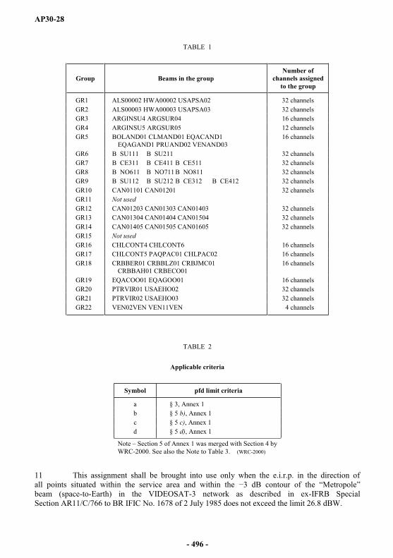
AP30-28
TABLE 1
Group Beams in the groupNumber of
channels assigned to the group
GR1 ALS00002 HWA00002 USAPSA02 32 channelsGR2 ALS00003 HWA00003 USAPSA03 32 channelsGR3 ARGINSU4 ARGSUR04 16 channelsGR4 ARGINSU5 ARGSUR05 12 channelsGR5 BOLAND01 CLMAND01 EQACAND1
EQAGAND1 PRUAND02 VENAND0316 channels
GR6 B SU111 B SU211 32 channelsGR7 B CE311 B CE411 B CE511 32 channelsGR8 B NO611 B NO711 B NO811 32 channelsGR9 B SU112 B SU212 B CE312 B CE412 32 channelsGR10 CAN01101 CAN01201 32 channelsGR11 Not usedGR12 CAN01203 CAN01303 CAN01403 32 channelsGR13 CAN01304 CAN01404 CAN01504 32 channelsGR14 CAN01405 CAN01505 CAN01605 32 channelsGR15 Not usedGR16 CHLCONT4 CHLCONT6 16 channelsGR17 CHLCONT5 PAQPAC01 CHLPAC02 16 channelsGR18 CRBBER01 CRBBLZ01 CRBJMC01
CRBBAH01 CRBECO0116 channels
GR19 EQACOO01 EQAGOO01 16 channelsGR20 PTRVIR01 USAEHO02 32 channelsGR21 PTRVIR02 USAEHO03 32 channelsGR22 VEN02VEN VEN11VEN 4 channels
TABLE 2
Applicable criteria
Symbol pfd limit criteria
a § 3, Annex 1b § 5 b), Annex 1c § 5 c), Annex 1d § 5 d), Annex 1
Note Section 5 of Annex 1 was merged with Section 4 by WRC-2000. See also the Note to Table 3. (WRC-2000)
11 This assignment shall be brought into use only when the e.i.r.p. in the direction of all points situated within the service area and within the dBbeam (space-to-Earth) in the VIDEOSAT-3 network as described in ex-IFRB Special Section AR11/C/766 to BR IFIC No. 1678 of 2 July 1985 does not exceed the limit 26.8 dBW.
- 496 -
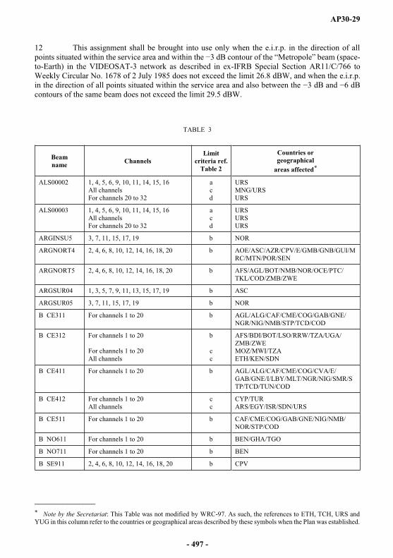
AP30-29
12 This assignment shall be brought into use only when the e.i.r.p. in the direction of all points situated within t 3 dB cont (space-to-Earth) in the VIDEOSAT-3 network as described in ex-IFRB Special Section AR11/C/766 to Weekly Circular No. 1678 of 2 July 1985 does not exceed the limit 26.8 dBW, and when the e.i.r.p. in the direction of all points situated within the service area and also between the 3 dB and 6 dB contours of the same beam does not exceed the limit 29.5 dBW.
TABLE 3
Beamname Channels
Limitcriteria ref.
Table 2
Countries or geographical
areas affected*
ALS00002 1, 4, 5, 6, 9, 10, 11, 14, 15, 16 All channels For channels 20 to 32
acd
URSMNG/URSURS
ALS00003 1, 4, 5, 6, 9, 10, 11, 14, 15, 16 All channels For channels 20 to 32
acd
URSURSURS
ARGINSU5 3, 7, 11, 15, 17, 19 b NOR
ARGNORT4 2, 4, 6, 8, 10, 12, 14, 16, 18, 20 b AOE/ASC/AZR/CPV/E/GMB/GNB/GUI/MRC/MTN/POR/SEN
ARGNORT5 2, 4, 6, 8, 10, 12, 14, 16, 18, 20 b AFS/AGL/BOT/NMB/NOR/OCE/PTC/TKL/COD/ZMB/ZWE
ARGSUR04 1, 3, 5, 7, 9, 11, 13, 15, 17, 19 b ASC
ARGSUR05 3, 7, 11, 15, 17, 19 b NOR
B CE311 For channels 1 to 20 b AGL/ALG/CAF/CME/COG/GAB/GNE/NGR/NIG/NMB/STP/TCD/COD
B CE312 For channels 1 to 20
For channels 1 to 20All channels
b
cc
AFS/BDI/BOT/LSO/RRW/TZA/UGA/ZMB/ZWEMOZ/MWI/TZAETH/KEN/SDN
B CE411 For channels 1 to 20 b AGL/ALG/CAF/CME/COG/CVA/E/GAB/GNE/I/LBY/MLT/NGR/NIG/SMR/STP/TCD/TUN/COD
B CE412 For channels 1 to 20All channels
cc
CYP/TURARS/EGY/ISR/SDN/URS
B CE511 For channels 1 to 20 b CAF/CME/COG/GAB/GNE/NIG/NMB/NOR/STP/COD
B NO611 For channels 1 to 20 b BEN/GHA/TGO
B NO711 For channels 1 to 20 b BEN
B SE911 2, 4, 6, 8, 10, 12, 14, 16, 18, 20 b CPV
_______________* Note by the Secretariat: This Table was not modified by WRC-97. As such, the references to ETH, TCH, URS and YUG in this column refer to the countries or geographical areas described by these symbols when the Plan was established.
- 497 -
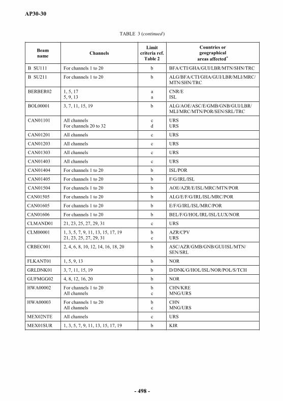
AP30-30
TABLE 3 (continued )
Beamname Channels
Limitcriteria ref.
Table 2
Countries or geographical
areas affected*
B SU111 For channels 1 to 20 b BFA/CTI/GHA/GUI/LBR/MTN/SHN/TRC
B SU211 For channels 1 to 20 b ALG/BFA/CTI/GHA/GUI/LBR/MLI/MRC/MTN/SHN/TRC
BERBER02 1, 5, 175, 9, 13
aa
CNR/EISL
BOL00001 3, 7, 11, 15, 19 b ALG/AOE/ASC/E/GMB/GNB/GUI/LBR/MLI/MRC/MTN/POR/SEN/SRL/TRC
CAN01101 All channelsFor channels 20 to 32
cd
URSURS
CAN01201 All channels c URS
CAN01203 All channels c URS
CAN01303 All channels c URS
CAN01403 All channels c URS
CAN01404 For channels 1 to 20 b ISL/POR
CAN01405 For channels 1 to 20 b F/G/IRL/ISL
CAN01504 For channels 1 to 20 b AOE/AZR/E/ISL/MRC/MTN/POR
CAN01505 For channels 1 to 20 b ALG/E/F/G/IRL/ISL/MRC/POR
CAN01605 For channels 1 to 20 b E/F/G/IRL/ISL/MRC/POR
CAN01606 For channels 1 to 20 b BEL/F/G/HOL/IRL/ISL/LUX/NOR
CLMAND01 21, 23, 25, 27, 29, 31 c URS
CLM00001 1, 3, 5, 7, 9, 11, 13, 15, 17, 1921, 23, 25, 27, 29, 31
bc
AZR/CPVURS
CRBEC001 2, 4, 6, 8, 10, 12, 14, 16, 18, 20 b ASC/AZR/GMB/GNB/GUI/ISL/MTN/SEN/SRL
FLKANT01 1, 5, 9, 13 b NOR
GRLDNK01 3, 7, 11, 15, 19 b D/DNK/G/HOL/ISL/NOR/POL/S/TCH
GUFMGG02 4, 8, 12, 16, 20 b NOR
HWA00002 For channels 1 to 20All channels
bc
CHN/KREMNG/URS
HWA00003 For channels 1 to 20All channels
bc
CHNMNG/URS
MEX02NTE All channels c URS
MEX01SUR 1, 3, 5, 7, 9, 11, 13, 15, 17, 19 b KIR
- 498 -

AP30-31
TABLE 3 (end )
Beamname Channels
Limitcriteria ref.
Table 2
Countries or geographical
areas affected*
MEX02SUR All channels c URS
PRU00004 2, 4, 6, 8, 10, 12, 14, 16, 18, 20 b ALG/AOE/ASC/BFA/CTI/E/G/GMB/GUI/ISL/LBR/MLI/MRC/MTN/POR/SEN/SHN/SRL/TRC
SPMFRAN3 1, 5, 9, 13, 17 b D/DNK/ISL/NOR/S
USAEH001 For channels 1 to 20 b ALG/AUT/BEL/CVA/D/DNK/E/F/G/HOL/I/ISL/LBY/LIE/LUX/MCO/MLT/NGR/NIG/NOR/OCE/SMR/SUI/TCH/TUN/YUG
USAEH002 For channels 1 to 20All channels
bc
AZR/CPV/HWLURS
USAEH003 For channels 1 to 20All channels
bc
MHLURS
USAEH004 For channels 1 to 20All channelsFor channels 20 to 32
bcd
WAKURSURS
USAWH101 All channels c URS
USAWH102 All channels c URS
VENAND03 21, 23, 25, 27, 29, 31 c URS
VEN11VEN 2, 4, 6, 8, 10, 12, 14, 16, 18, 2020, 22, 24, 26, 28, 30, 32
bc
AZR/CPVURS
Note The administrations listed in Table 3 were identified on the basis of the criteria adopted at the Regional Administrative Conference for the Planning of the Broadcasting-satellite Service in Region 2 (Geneva, 1983) (RARC Sat-R2), as shown in Table 2. WRC-2000 and WRC-03 revised the criteria applicable to determine affected administrations. Therefore, the Bureau, when receiving a notification for an assignment in the Region 2 Plan, shall determine which countries are affected on the basis of the revised criteria adopted by WRC-03, which may lead to a different set of affected administration(s) from that currently contained in Table 3. (WRC-07)
Country symbols
1 For the explanation of symbols designating countries or geographical areas in Region 2, see the Preface to the International Frequency List.
2 One additional symbol, CRB, has been created for the purposes of the 1983 Conference only, to designate to geographical area in the Caribbean Area. The five Caribbean beams are identified as follows:
CRBBAH01, CRBBER01, CRBBLZ01, CRBEC001 and CRBJMC01
and are intended collectively to provide coverage for the following countries or geographical areas: AIA, ATG, BAH, BER, BLZ, BRB, CYM, DMA, GRD, GUY, JMC, LCA, MSR, KNA, SUR, TCA, TRD, VCT and VRG to be so used if approved by them.
- 499 -
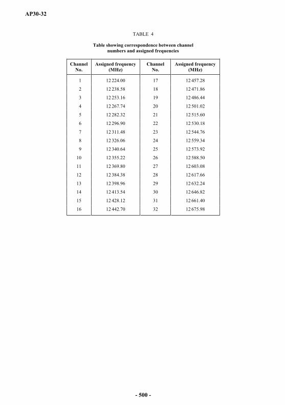
AP30-32
TABLE 4
Table showing correspondence between channel numbers and assigned frequencies
Channel No.
Assigned frequency(MHz)
Channel No.
Assigned frequency(MHz)
1 12 224.00 17 12 457.28
2 12 238.58 18 12 471.86
3 12 253.16 19 12 486.44
4 12 267.74 20 12 501.02
5 12 282.32 21 12 515.60
6 12 296.90 22 12 530.18
7 12 311.48 23 12 544.76
8 12 326.06 24 12 559.34
9 12 340.64 25 12 573.92
10 12 355.22 26 12 588.50
11 12 369.80 27 12 603.08
12 12 384.38 28 12 617.66
13 12 398.96 29 12 632.24
14 12 413.54 30 12 646.82
15 12 428.12 31 12 661.40
16 12 442.70 32 12 675.98
- 500 -

AP30-33
12 224.00 MHz (1)
1 2 3 4 5 6 7 8 9
ALS00002 1 58.37 3.76 1.24 170 1 59.7 9/GR1 10ALS00003 1 58.53 3.77 1.11 167 1 60.0 9/GR2 10ARGINSU4 1 3.40 0.80 19 1 59.9 9/GR3ARGSUR04 1 3.32 1.50 40 1 60.7 9/GR3 10B CE311 1 3.04 2.06 174 1 61.6 8 9/GR7 10B CE312 1 3.44 2.09 174 1 61.0 8 9/GR9 10B CE411 1 3.86 1.38 49 1 62.6 8 9/GR7 10B CE412 1 3.57 1.56 52 1 62.7 8 9/GR9 10B CE511 1 2.44 2.13 104 1 63.0 8 9/GR7 10B NO611 1 2.85 1.69 165 2 62.8 8 9/GR8 10B NO711 1 60.70 3.54 1.78 126 2 62.8 8 9/GR8 10B NO811 1 2.37 1.65 73 2 62.8 8 9/GR8B SU111 1 2.76 1.05 50 1 62.8 8 9/GR6 10B SU112 1 2.47 1.48 56 1 62.2 8 9/GR9B SU211 1 .95 3.22 1.36 60 1 62.5 8 9/GR6 10B SU212 1 3.20 1.96 58 1 61.3 8 9/GR9BAHIFRB1 1 24.16 1.81 0.80 142 1 61.6BERBERMU 1 32.32 0.80 0.80 90 2 56.8BERBER02 1 32.32 0.80 0.80 90 1 56.9 2 10BOLAND01 1 2.49 1.27 76 1 67.9 9/GR5CAN01101 1 57.24 3.45 1.27 157 1 59.5 9/GR10 10CAN01201 1 55.95 3.35 0.97 151 1 59.6 9/GR10 10CAN01202 1 55.63 2.74 1.12 32 1 59.6CAN01203 1 55.61 3.08 1.15 151 1 59.5 9/GR12 10CAN01303 1 57.12 3.54 0.91 154 1 60.0 9/GR12 10CAN01304 1 57.36 1.98 1.72 2 1 59.8 9/GR13CAN01403 1 52.02 4.68 0.80 148 1 61.8 9/GR12 10CAN01404 1 52.42 3.10 2.05 152 1 60.4 9/GR13 10CAN01405 1 52.39 2.84 2.29 172 1 60.3 9/GR14 10CAN01504 1 53.77 3.57 1.67 156 1 60.2 9/GR13 10CAN01505 1 53.79 3.30 1.89 162 1 60.1 9/GR14 10CAN01605 82.20 1 49.55 2.65 1.40 143 1 60.3 9/GR14 10CAN01606 1 49.55 2.40 1.65 148 1 60.2 10CHLCONT5 1 2.60 0.80 55 1 59.4 9/GR17CHLPAC02 1 1.36 0.80 69 1 59.2 9/GR17CLMAND01 1 .72 5.93 3.85 1.63 114 1 64.9 9/GR5CLM00001 1 5.87 3.98 1.96 118 1 63.5 10EQACAND1 1 1.37 0.95 75 1 64.0 9/GR5EQAGAND1 1 0.90 0.81 89 1 61.3 9/GR5FLKANT01 1 3.54 0.80 12 1 59.3 2 10FLKFALKS 1 0.80 0.80 90 1 58.1 2GRD00002 1 12.29 0.80 0.80 90 1 58.8HWA00002 1 23.42 4.20 0.80 160 1 58.8 9/GR1 10HWA00003 1 23.42 4.25 0.80 159 1 58.8 9/GR2 10MEX01NTE 1 26.01 2.89 2.08 155 1 60.5 1MEX01SUR 1 19.82 3.05 2.09 4 1 62.2 1 10MEX02NTE 1 26.31 3.84 1.55 148 1 61.2 1 10MEX02SUR 1 19.88 3.18 1.87 157 1 62.5 1 10PAQPAC01 1 8 0.80 0.80 90 1 56.2 9/GR17PRG00002 1 1.45 1.04 76 1 60.2PRUAND02 1 3.41 1.79 95 1 63.9 9/GR5PTRVIR01 1 18.12 0.80 0.80 90 1 60.5 1 6 9/GR20PTRVIR02 1 18.12 0.80 0.80 90 1 61.0 1 6 9/GR21SPMFRAN3 1 47.51 3.16 0.80 7 1 60.4 2 7 10TRD00001 1 10.70 0.80 0.80 90 1 59.4URG00001 1 1.02 0.89 11 1 60.0USAEH001 1 36.21 5.63 3.33 22 1 61.8 1 5 6 10USAEH002 1 36.16 5.67 3.76 170 1 61.7 1 6 9/GR20 10USAEH003 1 36.11 5.55 3.55 161 1 62.0 1 6 9/GR21 10USAEH004 1 36.05 5.38 3.24 152 1 62.6 1 5 6 10USAPSA02 1 40.58 4.03 0.82 135 1 63.2 9/GR1USAPSA03 1 40.12 3.62 0.80 136 1 65.0 9/GR2USAWH101 1 38.13 5.53 1.95 142 1 62.1 10USAWH102 1 38.57 5.51 1.54 138 1 63.2 10VENAND03 1 6.91 2.37 1.43 111 1 67.2 9/GR5VRG00001 .70 1 18.48 0.80 0.80 90 1 58.3 4
- 501 -

AP30-34
12 238.58 MHz (2)
1 2 3 4 5 6 7 8 9
ALS00002 2 58.52 3.81 1.23 171 2 59.7 9/GR1 10ALS00003 2 58.54 3.77 1.11 167 2 60.0 9/GR2 10ARGNORT4 2 3.86 1.99 48 2 65.6 10ARGNORT5 2 3.24 2.89 47 2 63.5 10ATNBEAM1 2 14.87 1.83 0.80 39 2 61.0B CE311 2 3.04 2.06 174 2 61.6 8 9/GR7 10B CE312 2 3.44 2.09 174 2 61.0 8 9/GR9 10B CE411 2 3.86 1.38 49 2 62.6 8 9/GR7 10B CE412 2 3.57 1.56 52 2 62.7 8 9/GR9 10B CE511 2 2.42 2.15 107 2 63.1 8 9/GR7 10B NO611 2 2.86 1.69 165 1 62.8 8 9/GR8 10B NO711 2 3.54 1.78 126 1 62.8 8 9/GR8 10B NO811 2 2.37 1.65 73 1 62.8 8 9/GR8B SE911 2 2.22 0.80 62 2 65.3 8 10B SU111 2 2.76 1.06 50 2 62.8 8 9/GR6 10B SU112 80 2 2.47 1.48 56 2 62.3 8 9/GR9B SU211 2 3.22 1.37 60 2 62.5 8 9/GR6 10B SU212 2 3.27 1.92 59 2 61.3 8 9/GR9CAN01101 2 57.24 3.45 1.27 157 2 59.5 9/GR10 10CAN01201 2 55.89 3.33 0.98 151 2 59.6 9/GR10 10CAN01202 2 55.62 2.75 1.11 32 2 59.6CAN01203 2 55.56 3.07 1.15 151 2 59.5 9/GR12 10CAN01303 2 57.12 3.54 0.92 154 2 60.0 9/GR12 10CAN01304 2 57.33 1.96 1.73 1 2 59.8 9/GR13CAN01403 2 52.02 4.67 0.80 148 2 61.8 9/GR12 10CAN01404 2 52.41 3.09 2.06 153 2 60.4 9/GR13 10CAN01405 2 52.34 2.82 2.30 172 2 60.3 9/GR14 10CAN01504 2 53.78 3.57 1.67 157 2 60.2 9/GR13 10CAN01505 2 53.76 3.30 1.89 162 2 60.1 9/GR14 10CAN01605 2 49.50 2.66 1.39 144 2 60.3 9/GR14 10CAN01606 2 49.51 2.41 1.65 148 2 60.2 10CHLCONT4 2 2.21 0.80 68 2 59.1 9/GR16CHLCONT6 2 3.65 1.31 39 2 59.6 9/GR16CRBBAH01 2 24.13 1.83 0.80 141 1 61.7 9/GR18CRBBER01 2 32.13 0.80 0.80 90 1 56.7 9/GR18CRBBLZ01 2 17.26 0.80 0.80 90 1 58.6 9/GR18CRBEC001 2 8.26 4.20 0.86 115 1 64.2 9/GR18 10CRBJMC01 2 17.97 0.99 0.80 151 1 61.1 9/GR18CTR00201 2 9.67 0.82 0.80 119 2 65.6EQAC0001 2 1.48 1.15 65 1 63.0 9/GR19EQAG0001 94.80 2 0.94 0.89 99 1 61.0 9/GR19GUY00302 2 4.77 1.43 0.85 91 2 63.5HNDIFRB2 2 15.16 1.14 0.85 8 1 63.4HTI00002 2 18.96 0.82 0.80 11 2 60.9HWA00002 2 23.32 4.20 0.80 160 2 58.8 9/GR1 10HWA00003 2 23.42 4.25 0.80 159 2 58.8 9/GR2 10MEX01NTE 2 25.99 2.88 2.07 155 2 60.5 1MEX02NTE 2 26.32 3.80 1.57 149 2 61.2 1 10MEX02SUR 2 19.88 3.19 1.87 158 2 62.5 1 10PRU00004 2 3.74 2.45 112 2 62.8 10PTRVIR01 2 18.12 0.80 0.80 90 2 60.6 1 6 9/GR20PTRVIR02 2 18.12 0.80 0.80 90 2 61.1 1 6 9/GR21TCA00001 2 21.53 0.80 0.80 90 2 60.4USAEH001 1.30 2 36.21 5.63 3.32 22 2 61.8 1 5 6 10USAEH002 2 36.16 5.65 3.78 170 2 61.7 1 6 9/GR20 10USAEH003 2 36.11 5.55 3.56 161 2 62.1 1 6 9/GR21 10USAEH004 2 36.05 5.38 3.24 153 2 62.6 1 5 6 10USAPSA02 2 40.58 4.04 0.82 135 2 63.2 9/GR1USAPSA03 2 40.15 3.63 0.80 136 2 64.9 9/GR2USAWH101 2 38.13 5.52 1.96 142 2 62.1 10USAWH102 2 38.57 5.51 1.55 138 2 63.2 10VCT00001 2 .18 13.23 0.80 0.80 90 2 58.4VEN11VEN 2 6.90 2.50 1.77 122 2 65.1 10
- 502 -

AP30-35
12 253.16 MHz (3)
1 2 3 4 5 6 7 8 9
ALS00002 3 58.37 3.76 1.24 170 1 59.8 9/GR1 10ALS00003 3 58.53 3.77 1.11 167 1 60.0 9/GR2 10ARGINSU4 3 3.40 0.80 19 1 59.9 9/GR3ARGINSU5 3 3.77 0.80 13 1 59.3 9/GR4 10ARGSUR04 3 3.32 1.50 40 1 60.7 9/GR3 10ARGSUR05 3 2.54 2.38 152 1 60.1 9/GR4 10ATGSJN01 3 17.07 0.80 0.80 90 1 58.4B CE311 3 3.04 2.06 174 1 61.6 8 9/GR7 10B CE312 3 3.44 2.09 174 1 61.0 8 9/GR9 10B CE411 3 3.86 1.38 49 1 62.6 8 9/GR7 10B CE412 20 3 3.57 1.56 52 1 62.7 8 9/GR9 10B CE511 3 2.44 2.13 104 1 63.1 8 9/GR7 10B NO611 3 2.85 1.69 165 2 62.9 8 9/GR8 10B NO711 3 3.54 1.78 126 2 62.8 8 9/GR8 10B NO811 3 2.37 1.65 73 2 62.8 8 9/GR8B SU111 3 2.76 1.05 50 1 62.9 8 9/GR6 10B SU112 3 2.47 1.48 56 1 62.3 8 9/GR9B SU211 3 3.22 1.36 60 1 62.5 8 9/GR6 10B SU212 3 3.20 1.96 58 1 61.3 8 9/GR9BERBERMU 3 32.32 0.80 0.80 90 2 56.8BOLAND01 3 2.49 1.27 76 1 67.9 9/GR5BOL00001 3 2.52 2.19 85 1 63.8 10BRB00001 3 12.93 0.80 0.80 90 2 59.1CAN01101 3 57.24 3.45 1.27 157 1 59.5 9/GR10 10CAN01201 3 55.95 3.35 0.97 151 1 59.6 9/GR10 10CAN01202 3 55.63 2.74 1.12 32 1 59.6CAN01203 3 55.61 3.08 1.15 151 1 59.5 9/GR12 10CAN01303 3 57.12 3.54 0.91 154 1 60.1 9/GR12 10CAN01304 3 57.36 1.98 1.72 2 1 59.8 9/GR13CAN01403 3 52.02 4.68 0.80 148 1 61.8 9/GR12 10CAN01404 3 52.42 3.10 2.05 152 1 60.4 9/GR13 10CAN01405 3 52.39 2.84 2.29 172 1 60.3 9/GR14 10CAN01504 3 53.77 3.57 1.67 156 1 60.2 9/GR13 10CAN01505 3 53.79 3.30 1.89 162 1 60.1 9/GR14 10CAN01605 3 49.55 2.65 1.40 143 1 60.3 9/GR14 10CAN01606 3 49.55 2.40 1.65 148 1 60.2 10CHLCONT5 3 2.60 0.80 55 1 59.4 9/GR17CHLPAC02 3 1.36 0.80 69 1 59.2 9/GR17CLMAND01 3 5.93 3.85 1.63 114 1 65.0 9/GR5CLM00001 3 50 5.87 3.98 1.96 118 1 63.6 10CUB00001 3 21.62 2.24 0.80 168 1 61.1EQACAND1 3 1.37 0.95 75 1 64.1 9/GR5EQAGAND1 3 0.90 0.81 89 1 61.3 9/GR5GRD00002 3 12.29 0.80 0.80 90 1 58.8GRD00059 3 12.29 0.80 0.80 90 1 58.5GRLDNK01 3 66.56 2.70 0.82 173 1 60.0 2 10HWA00002 3 23.42 4.20 0.80 160 1 58.8 9/GR1 10HWA00003 3 23.42 4.25 0.80 159 1 58.8 9/GR2 10MEX01NTE 3 26.01 2.89 2.08 155 1 60.5 1MEX01SUR 3 19.82 3.05 2.09 4 1 62.3 1 10MEX02NTE 3 26.31 3.84 1.55 148 1 61.2 1 10MEX02SUR 3 19.88 3.18 1.87 157 1 62.6 1 10PAQPAC01 3 0.80 0.80 90 1 56.2 9/GR17PRG00002 3 1.45 1.04 76 1 60.2PRUAND02 3 3.41 1.79 95 1 64.0 9/GR5PTRVIR01 3 18.12 0.80 0.80 90 1 60.6 1 6 9/GR20PTRVIR02 3 18.12 0.80 0.80 90 1 61.0 1 6 9/GR21SURINAM2 3 4.35 1.00 0.80 86 1 63.2URG00001 3 1.02 0.89 11 1 60.0USAEH001 3 36.21 5.63 3.33 22 1 61.8 1 5 6 10USAEH002 3 36.16 5.67 3.76 170 1 61.7 1 6 9/GR20 10USAEH003 3 36.11 5.55 3.55 161 1 62.1 1 6 9/GR21 10USAEH004 3 36.05 5.38 3.24 152 1 62.6 1 5 6 10USAPSA02 3 40.58 4.03 0.82 135 1 63.3 9/GR1USAPSA03 3 40.12 3.62 0.80 136 1 65.0 9/GR2USAWH101 3 38.13 5.53 1.95 142 1 62.1 10USAWH102 3 38.57 5.51 1.54 138 1 63.2 10VENAND03 3 6.91 2.37 1.43 111 1 67.3 9/GR5
- 503 -

AP30-36
12 267.74 MHz (4)
1 2 3 4 5 6 7 8 9
ALS00002 4 58.52 3.81 1.23 171 2 59.8 9/GR1 10ALS00003 4 58.54 3.77 1.11 167 2 60.0 9/GR2 10ARGNORT4 4 3.86 1.99 48 2 65.7 10ARGNORT5 4 3.24 2.89 47 2 63.5 10B CE311 4 3.04 2.06 174 2 61.6 8 9/GR7 10B CE312 4 3.44 2.09 174 2 61.0 8 9/GR9 10B CE411 4 3.86 1.38 49 2 62.6 8 9/GR7 10B CE412 4 3.57 1.56 52 2 62.8 8 9/GR9 10B CE511 4 2.42 2.15 107 2 63.1 8 9/GR7 10B NO611 4 2.86 1.69 165 1 62.9 8 9/GR8 10B NO711 4 3.54 1.78 126 1 62.8 8 9/GR8 10B NO811 4 2.37 1.65 73 1 62.8 8 9/GR8B SE911 4 2.22 0.80 62 2 65.3 8 10B SU111 4 2.76 1.06 50 2 62.9 8 9/GR6 10B SU112 4 2.47 1.48 56 2 62.3 8 9/GR9B SU211 4 3.22 1.37 60 2 62.5 8 9/GR6 10B SU212 4 3.27 1.92 59 2 61.3 8 9/GR9CAN01101 4 57.24 3.45 1.27 157 2 59.5 9/GR10 10CAN01201 4 55.89 3.33 0.98 151 2 59.6 9/GR10 10CAN01202 4 55.62 2.75 1.11 32 2 59.6CAN01203 4 55.56 3.07 1.15 151 2 59.5 9/GR12 10CAN01303 28.80 4 57.12 3.54 0.92 154 2 60.1 9/GR12 10CAN01304 4 57.33 1.96 1.73 1 2 59.8 9/GR13CAN01403 4 52.02 4.67 0.80 148 2 61.8 9/GR12 10CAN01404 4 52.41 3.09 2.06 153 2 60.4 9/GR13 10CAN01405 4 52.34 2.82 2.30 172 2 60.3 9/GR14 10CAN01504 4 53.78 3.57 1.67 157 2 60.2 9/GR13 10CAN01505 4 53.76 3.30 1.89 162 2 60.2 9/GR14 10CAN01605 4 49.50 2.66 1.39 144 2 60.3 9/GR14 10CAN01606 4 1.32 49.51 2.41 1.65 148 2 60.2 10CHLCONT4 4 2.21 0.80 68 2 59.1 9/GR16CHLCONT6 4 3.65 1.31 39 2 59.6 9/GR16CRBBAH01 4 24.13 1.83 0.80 141 1 61.7 9/GR18CRBBER01 4 32.13 0.80 0.80 90 1 56.8 9/GR18CRBBLZ01 4 17.26 0.80 0.80 90 1 58.7 9/GR18CRBEC001 4 8.26 4.20 0.86 115 1 64.3 9/GR18 10CRBJMC01 4 17.97 0.99 0.80 151 1 61.1 9/GR18CYM00001 4 19.57 0.80 0.80 90 2 59.6DOMIFRB2 4 18.79 0.98 0.80 167 2 61.1EQAC0001 4 1.48 1.15 65 1 63.0 9/GR19EQAG0001 4 0.94 0.89 99 1 61.0 9/GR19GUFMGG02 4 8.47 4.16 0.81 123 2 62.7 2 7 10HWA00002 80 4 23.32 4.20 0.80 160 2 58.8 9/GR1 10HWA00003 4 23.42 4.25 0.80 159 2 58.8 9/GR2 10JMC00005 4 18.12 0.80 0.80 90 2 60.6LCAIFRB1 4 13.90 0.80 0.80 90 2 58.4MEX01NTE 4 25.99 2.88 2.07 155 2 60.5 1MEX02NTE 4 26.32 3.80 1.57 149 2 61.2 1 10MEX02SUR 4 19.88 3.19 1.87 158 2 62.5 1 10PRU00004 4 3.74 2.45 112 2 62.9 10PTRVIR01 4 18.12 0.80 0.80 90 2 60.6 1 6 9/GR20PTRVIR02 4 18.12 0.80 0.80 90 2 61.1 1 6 9/GR21SLVIFRB2 4 13.59 0.80 0.80 90 1 61.7USAEH001 4 36.21 5.63 3.32 22 2 61.9 1 5 6 10USAEH002 4 36.16 5.65 3.78 170 2 61.7 1 6 9/GR20 10USAEH003 4 36.11 5.55 3.56 161 2 62.1 1 6 9/GR21 10USAEH004 4 36.05 5.38 3.24 153 2 62.6 1 5 6 10USAPSA02 4 40.58 4.04 0.82 135 2 63.3 9/GR1USAPSA03 4 40.15 3.63 0.80 136 2 65.0 9/GR2USAWH101 4 38.13 5.52 1.96 142 2 62.1 10USAWH102 4 38.57 5.51 1.55 138 2 63.2 10VEN11VEN 4 6.90 2.50 1.77 122 2 65.2 10
- 504 -

AP30-37
12 282.32 MHz (5)
1 2 3 4 5 6 7 8 9
ALS00002 5 58.37 3.76 1.24 170 1 59.7 9/GR1 10ALS00003 5 58.53 3.77 1.11 167 1 60.0 9/GR2 10ARGINSU4 5 3.40 0.80 19 1 59.9 9/GR3ARGSUR04 5 3.32 1.50 40 1 60.7 9/GR3 10B CE311 5 3.04 2.06 174 1 61.6 89/GR7 10B CE312 5 3.44 2.09 174 1 61.0 89/GR9 10B CE411 5 3.86 1.38 49 1 62.6 89/GR7 10B CE412 5 3.57 1.56 52 1 62.7 89/GR9 10B CE511 5 2.44 2.13 104 1 63.0 89/GR7 10B NO611 5 2.85 1.69 165 2 62.8 89/GR8 10B NO711 5 3.54 1.78 126 2 62.8 89/GR8 10B NO811 5 2.37 1.65 73 2 62.8 89/GR8B SU111 5 2.76 1.05 50 1 62.8 89/GR6 10B SU112 5 2.47 1.48 56 1 62.2 89/GR9B SU211 5 3.22 1.36 60 1 62.5 89/GR6 10B SU212 5 3.20 1.96 58 1 61.3 89/GR9BAHIFRB1 5 24.16 1.81 0.80 142 1 61.6BERBERMU 5 32.32 0.80 0.80 90 2 56.8BERBER02 5 32.32 0.80 0.80 90 1 56.9 2 10BOLAND01 5 2.49 1.27 76 1 67.9 9/GR5CAN01101 5 57.24 3.45 1.27 157 1 59.5 9/GR10 10CAN01201 5 12.04 55.95 3.35 0.97 151 1 59.6 9/GR10 10CAN01202 5 55.63 2.74 1.12 32 1 59.6CAN01203 5 55.61 3.08 1.15 151 1 59.5 9/GR12 10CAN01303 5 57.12 3.54 0.91 154 1 60.0 9/GR12 10CAN01304 5 57.36 1.98 1.72 2 1 59.8 9/GR13CAN01403 5 52.02 4.68 0.80 148 1 61.8 9/GR12 10CAN01404 5 52.42 3.10 2.05 152 1 60.4 9/GR13 10CAN01405 5 52.39 2.84 2.29 172 1 60.3 9/GR14 10CAN01504 5 53.77 3.57 1.67 156 1 60.2 9/GR13 10CAN01505 5 53.79 3.30 1.89 162 1 60.1 9/GR14 10CAN01605 5 49.55 2.65 1.40 143 1 60.3 9/GR14 10CAN01606 5 49.55 2.40 1.65 148 1 60.2 10CHLCONT5 5 2.60 0.80 55 1 59.4 9/GR17CHLPAC02 5 1.36 0.80 69 1 59.2 9/GR17CLMAND01 5 5.93 3.85 1.63 114 1 64.9 9/GR5CLM00001 5 5.87 3.98 1.96 118 1 63.5 10EQACAND1 5 1.37 0.95 75 1 64.0 9/GR5EQAGAND1 5 0.90 0.81 89 1 61.3 9/GR5FLKANT01 5 3.54 0.80 12 1 59.3 2 10FLKFALKS 5 0.80 0.80 90 1 58.1 2GRD00002 5 12.29 0.80 0.80 90 1 58.8HWA00002 5 23.42 4.20 0.80 160 1 58.8 9/GR1 10HWA00003 5 23.42 4.25 0.80 159 1 58.8 9/GR2 10MEX01NTE 5 26.01 2.89 2.08 155 1 60.5 1MEX01SUR 5 19.82 3.05 2.09 4 1 62.2 1 10MEX02NTE 5 26.31 3.84 1.55 148 1 61.2 1 10MEX02SUR 5 19.88 3.18 1.87 157 1 62.5 1 10PAQPAC01 5 0.80 0.80 90 1 56.2 9/GR17PRG00002 5 1.45 1.04 76 1 60.2PRUAND02 5 3.41 1.79 95 1 63.9 9/GR5PTRVIR01 5 18.12 0.80 0.80 90 1 60.5 169/GR20PTRVIR02 5 18.12 0.80 0.80 90 1 61.0 169/GR21SPMFRAN3 5 47.51 3.16 0.80 7 1 60.4 27 10TRD00001 5 10.70 0.80 0.80 90 1 59.4URG00001 5 1.02 0.89 11 1 60.0USAEH001 5 36.21 5.63 3.33 22 1 61.8 156 10USAEH002 5 36.16 5.67 3.76 170 1 61.7 169/GR20 10USAEH003 5 36.11 5.55 3.55 161 1 62.0 169/GR21 10USAEH004 5 36.05 5.38 3.24 152 1 62.6 156 10USAPSA02 5 40.58 4.03 0.82 135 1 63.2 9/GR1USAPSA03 5 40.12 3.62 0.80 136 1 65.0 9/GR2USAWH101 5 38.13 5.53 1.95 142 1 62.1 10USAWH102 5 38.57 5.51 1.54 138 1 63.2 10VENAND03 5 6.91 2.37 1.43 111 1 67.2 9/GR5VRG00001 5 18.48 0.80 0.80 90 1 58.3 4
- 505 -

AP30-38
12 296.90 MHz (6)
1 2 3 4 5 6 7 8 9
ALS00002 6 58.52 3.81 1.23 171 2 59.7 9/GR1 10ALS00003 6 58.54 3.77 1.11 167 2 60.0 9/GR2 10ARGNORT4 6 3.86 1.99 48 2 65.6 10ARGNORT5 6 3.24 2.89 47 2 63.5 10ATNBEAM1 6 14.87 1.83 0.80 39 2 61.0B CE311 6 3.04 2.06 174 2 61.6 8 9/GR7 10B CE312 6 3.44 2.09 174 2 61.0 8 9/GR9 10B CE411 6 3.86 1.38 49 2 62.6 8 9/GR7 10B CE412 6 3.57 1.56 52 2 62.7 8 9/GR9 10B CE511 6 98 2.42 2.15 107 2 63.1 8 9/GR7 10B NO611 6 2.86 1.69 165 1 62.8 8 9/GR8 10B NO711 6 3.54 1.78 126 1 62.8 8 9/GR8 10B NO811 6 2.37 1.65 73 1 62.8 8 9/GR8B SE911 6 2.22 0.80 62 2 65.3 8 10B SU111 6 2.76 1.06 50 2 62.8 8 9/GR6 10B SU112 6 2.47 1.48 56 2 62.3 8 9/GR9B SU211 6 3.22 1.37 60 2 62.5 8 9/GR6 10B SU212 6 3.27 1.92 59 2 61.3 8 9/GR9CAN01101 6 57.24 3.45 1.27 157 2 59.5 9/GR10 10CAN01201 6 55.89 3.33 0.98 151 2 59.6 9/GR10 10CAN01202 6 55.62 2.75 1.11 32 2 59.6CAN01203 6 55.56 3.07 1.15 151 2 59.5 9/GR12 10CAN01303 6 57.12 3.54 0.92 154 2 60.0 9/GR12 10CAN01304 6 57.33 1.96 1.73 1 2 59.8 9/GR13CAN01403 6 52.02 4.67 0.80 148 2 61.8 9/GR12 10CAN01404 6 52.41 3.09 2.06 153 2 60.4 9/GR13 10CAN01405 6 52.34 2.82 2.30 172 2 60.3 9/GR14 10CAN01504 6 53.78 3.57 1.67 157 2 60.2 9/GR13 10CAN01505 6 53.76 3.30 1.89 162 2 60.1 9/GR14 10CAN01605 6 49.50 2.66 1.39 144 2 60.3 9/GR14 10CAN01606 6 49.51 2.41 1.65 148 2 60.2 10CHLCONT4 6 2.21 0.80 68 2 59.1 9/GR16CHLCONT6 6 3.65 1.31 39 2 59.6 9/GR16CRBBAH01 6 24.13 1.83 0.80 141 1 61.7 9/GR18CRBBER01 .30 6 32.13 0.80 0.80 90 1 56.7 9/GR18CRBBLZ01 6 17.26 0.80 0.80 90 1 58.6 9/GR18CRBEC001 6 8.26 4.20 0.86 115 1 64.2 9/GR18 10CRBJMC01 6 17.97 0.99 0.80 151 1 61.1 9/GR18CTR00201 6 9.67 0.82 0.80 119 2 65.6EQAC0001 6 1.48 1.15 65 1 63.0 9/GR19EQAG0001 6 0.94 0.89 99 1 61.0 9/GR19GUY00302 6 4.77 1.43 0.85 91 2 63.5HNDIFRB2 6 15.16 1.14 0.85 8 1 63.4HTI00002 6 18.96 0.82 0.80 11 2 60.9HWA00002 6 23.32 4.20 0.80 160 2 58.8 9/GR1 10HWA00003 6 23.42 4.25 0.80 159 2 58.8 9/GR2 10MEX01NTE 6 25.99 2.88 2.07 155 2 60.5 1MEX02NTE 6 26.32 3.80 1.57 149 2 61.2 1 10MEX02SUR 6 19.88 3.19 1.87 158 2 62.5 1 10PRU00004 6 3.74 2.45 112 2 62.8 10PTRVIR01 6 18.12 0.80 0.80 90 2 60.6 1 6 9/GR20PTRVIR02 6 18.12 0.80 0.80 90 2 61.1 1 6 9/GR21TCA00001 6 21.53 0.80 0.80 90 2 60.4USAEH001 6 36.21 5.63 3.32 22 2 61.8 1 5 6 10USAEH002 6 36.16 5.65 3.78 170 2 61.7 1 6 9/GR20 10USAEH003 6 36.11 5.55 3.56 161 2 62.1 1 6 9/GR21 10USAEH004 6 36.05 5.38 3.24 153 2 62.6 1 5 6 10USAPSA02 6 40.58 4.04 0.82 135 2 63.2 9/GR1USAPSA03 6 40.15 3.63 0.80 136 2 64.9 9/GR2USAWH101 6 38.13 5.52 1.96 142 2 62.1 10USAWH102 6 38.57 5.51 1.55 138 2 63.2 10VCT00001 6 13.23 0.80 0.80 90 2 58.4VEN11VEN 6 6.90 2.50 1.77 122 2 65.1 10
- 506 -
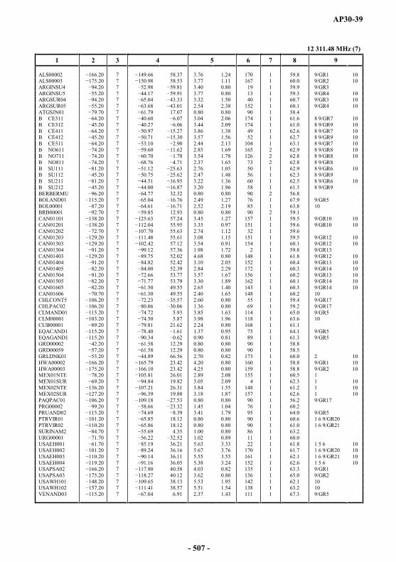
AP30-39
12 311.48 MHz (7)
1 2 3 4 5 6 7 8 9
ALS00002 7 58.37 3.76 1.24 170 1 59.8 9/GR1 10ALS00003 7 58.53 3.77 1.11 167 1 60.0 9/GR2 10ARGINSU4 7 3.40 0.80 19 1 59.9 9/GR3ARGINSU5 7 3.77 0.80 13 1 59.3 9/GR4 10ARGSUR04 7 3.32 1.50 40 1 60.7 9/GR3 10ARGSUR05 7 2.54 2.38 152 1 60.1 9/GR4 10ATGSJN01 7 17.07 0.80 0.80 90 1 58.4B CE311 7 3.04 2.06 174 1 61.6 8 9/GR7 10B CE312 7 3.44 2.09 174 1 61.0 8 9/GR9 10B CE411 7 3.86 1.38 49 1 62.6 8 9/GR7 10B CE412 7 3.57 1.56 52 1 62.7 8 9/GR9 10B CE511 7 2.44 2.13 104 1 63.1 8 9/GR7 10B NO611 7 2.85 1.69 165 2 62.9 8 9/GR8 10B NO711 7 3.54 1.78 126 2 62.8 8 9/GR8 10B NO811 7 2.37 1.65 73 2 62.8 8 9/GR8B SU111 7 2.76 1.05 50 1 62.9 8 9/GR6 10B SU112 7 2.47 1.48 56 1 62.3 8 9/GR9B SU211 7 3.22 1.36 60 1 62.5 8 9/GR6 10B SU212 7 3.20 1.96 58 1 61.3 8 9/GR9BERBERMU 7 32.32 0.80 0.80 90 2 56.8BOLAND01 7 2.49 1.27 76 1 67.9 9/GR5BOL00001 7 2.52 2.19 85 1 63.8 10BRB00001 7 12.93 0.80 0.80 90 2 59.1CAN01101 7 57.24 3.45 1.27 157 1 59.5 9/GR10 10CAN01201 7 55.95 3.35 0.97 151 1 59.6 9/GR10 10CAN01202 7 107.70 55.63 2.74 1.12 32 1 59.6CAN01203 7 55.61 3.08 1.15 151 1 59.5 9/GR12 10CAN01303 7 57.12 3.54 0.91 154 1 60.1 9/GR12 10CAN01304 7 57.36 1.98 1.72 2 1 59.8 9/GR13CAN01403 7 52.02 4.68 0.80 148 1 61.8 9/GR12 10CAN01404 7 52.42 3.10 2.05 152 1 60.4 9/GR13 10CAN01405 7 52.39 2.84 2.29 172 1 60.3 9/GR14 10CAN01504 7 53.77 3.57 1.67 156 1 60.2 9/GR13 10CAN01505 7 53.79 3.30 1.89 162 1 60.1 9/GR14 10CAN01605 7 49.55 2.65 1.40 143 1 60.3 9/GR14 10CAN01606 7 49.55 2.40 1.65 148 1 60.2 10CHLCONT5 7 2.60 0.80 55 1 59.4 9/GR17CHLPAC02 7 1.36 0.80 69 1 59.2 9/GR17CLMAND01 7 5.93 3.85 1.63 114 1 65.0 9/GR5CLM00001 7 5.87 3.98 1.96 118 1 63.6 10CUB00001 7 21.62 2.24 0.80 168 1 61.1EQACAND1 7 1.37 0.95 75 1 64.1 9/GR5EQAGAND1 7 0.90 0.81 89 1 61.3 9/GR5GRD00002 7 12.29 0.80 0.80 90 1 58.8GRD00059 7 12.29 0.80 0.80 90 1 58.5GRLDNK01 7 66.56 2.70 0.82 173 1 60.0 2 10HWA00002 7 23.42 4.20 0.80 160 1 58.8 9/GR1 10HWA00003 7 23.42 4.25 0.80 159 1 58.8 9/GR2 10MEX01NTE 7 26.01 2.89 2.08 155 1 60.5 1MEX01SUR 7 19.82 3.05 2.09 4 1 62.3 1 10MEX02NTE 7 26.31 3.84 1.55 148 1 61.2 1 10MEX02SUR 7 19.88 3.18 1.87 157 1 62.6 1 10PAQPAC01 7 0.80 0.80 90 1 56.2 9/GR17PRG00002 7 1.45 1.04 76 1 60.2PRUAND02 7 3.41 1.79 95 1 64.0 9/GR5PTRVIR01 01.20 7 18.12 0.80 0.80 90 1 60.6 1 6 9/GR20PTRVIR02 7 18.12 0.80 0.80 90 1 61.0 1 6 9/GR21SURINAM2 7 4.35 1.00 0.80 86 1 63.2URG00001 7 1.02 0.89 11 1 60.0USAEH001 7 36.21 5.63 3.33 22 1 61.8 1 5 6 10USAEH002 7 36.16 5.67 3.76 170 1 61.7 1 6 9/GR20 10USAEH003 7 36.11 5.55 3.55 161 1 62.1 1 6 9/GR21 10USAEH004 7 36.05 5.38 3.24 152 1 62.6 1 5 6 10USAPSA02 7 0 40.58 4.03 0.82 135 1 63.3 9/GR1USAPSA03 7 40.12 3.62 0.80 136 1 65.0 9/GR2USAWH101 7 38.13 5.53 1.95 142 1 62.1 10USAWH102 7 38.57 5.51 1.54 138 1 63.2 10VENAND03 7 6.91 2.37 1.43 111 1 67.3 9/GR5
- 507 -
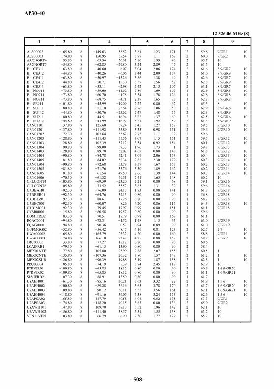
AP30-40
12 326.06 MHz (8)
1 2 3 4 5 6 7 8 9
ALS00002 8 58.52 3.81 1.23 171 2 59.8 9/GR1 10ALS00003 8 58.54 3.77 1.11 167 2 60.0 9/GR2 10ARGNORT4 8 3.86 1.99 48 2 65.7 10ARGNORT5 8 3.24 2.89 47 2 63.5 10B CE311 8 3.04 2.06 174 2 61.6 8 9/GR7 10B CE312 8 3.44 2.09 174 2 61.0 8 9/GR9 10B CE411 8 3.86 1.38 49 2 62.6 8 9/GR7 10B CE412 .80 8 3.57 1.56 52 2 62.8 8 9/GR9 10B CE511 8 2.42 2.15 107 2 63.1 8 9/GR7 10B NO611 8 2.86 1.69 165 1 62.9 8 9/GR8 10B NO711 8 3.54 1.78 126 1 62.8 8 9/GR8 10B NO811 8 2.37 1.65 73 1 62.8 8 9/GR8B SE911 8 2.22 0.80 62 2 65.3 8 10B SU111 8 2.76 1.06 50 2 62.9 8 9/GR6 10B SU112 8 2.47 1.48 56 2 62.3 8 9/GR9B SU211 8 94 3.22 1.37 60 2 62.5 8 9/GR6 10B SU212 8 3.27 1.92 59 2 61.3 8 9/GR9CAN01101 8 57.24 3.45 1.27 157 2 59.5 9/GR10 10CAN01201 8 55.89 3.33 0.98 151 2 59.6 9/GR10 10CAN01202 8 55.62 2.75 1.11 32 2 59.6CAN01203 8 55.56 3.07 1.15 151 2 59.5 9/GR12 10CAN01303 8 57.12 3.54 0.92 154 2 60.1 9/GR12 10CAN01304 8 57.33 1.96 1.73 1 2 59.8 9/GR13CAN01403 8 52.02 4.67 0.80 148 2 61.8 9/GR12 10CAN01404 8 52.41 3.09 2.06 153 2 60.4 9/GR13 10CAN01405 8 52.34 2.82 2.30 172 2 60.3 9/GR14 10CAN01504 8 53.78 3.57 1.67 157 2 60.2 9/GR13 10CAN01505 8 53.76 3.30 1.89 162 2 60.2 9/GR14 10CAN01605 8 49.50 2.66 1.39 144 2 60.3 9/GR14 10CAN01606 8 49.51 2.41 1.65 148 2 60.2 10CHLCONT4 8 2.21 0.80 68 2 59.1 9/GR16CHLCONT6 8 3.65 1.31 39 2 59.6 9/GR16CRBBAH01 8 24.13 1.83 0.80 141 1 61.7 9/GR18CRBBER01 8 32.13 0.80 0.80 90 1 56.8 9/GR18CRBBLZ01 8 17.26 0.80 0.80 90 1 58.7 9/GR18CRBEC001 8 8.26 4.20 0.86 115 1 64.3 9/GR18 10CRBJMC01 8 17.97 0.99 0.80 151 1 61.1 9/GR18CYM00001 8 19.57 0.80 0.80 90 2 59.6DOMIFRB2 8 18.79 0.98 0.80 167 2 61.1EQAC0001 8 1.48 1.15 65 1 63.0 9/GR19EQAG0001 8 0.94 0.89 99 1 61.0 9/GR19GUFMGG02 8 8.47 4.16 0.81 123 2 62.7 2 7 10HWA00002 8 23.32 4.20 0.80 160 2 58.8 9/GR1 10HWA00003 8 23.42 4.25 0.80 159 2 58.8 9/GR2 10JMC00005 8 18.12 0.80 0.80 90 2 60.6LCAIFRB1 8 13.90 0.80 0.80 90 2 58.4MEX01NTE 8 25.99 2.88 2.07 155 2 60.5 1MEX02NTE 8 26.32 3.80 1.57 149 2 61.2 1 10MEX02SUR 8 19.88 3.19 1.87 158 2 62.5 1 10PRU00004 80 8 3.74 2.45 112 2 62.9 10PTRVIR01 8 18.12 0.80 0.80 90 2 60.6 1 6 9/GR20PTRVIR02 8 18.12 0.80 0.80 90 2 61.1 1 6 9/GR21SLVIFRB2 8 13.59 0.80 0.80 90 1 61.7USAEH001 8 36.21 5.63 3.32 22 2 61.9 1 5 6 10USAEH002 8 36.16 5.65 3.78 170 2 61.7 1 6 9/GR20 10USAEH003 8 36.11 5.55 3.56 161 2 62.1 1 6 9/GR21 10USAEH004 8 36.05 5.38 3.24 153 2 62.6 1 5 6 10USAPSA02 8 .79 40.58 4.04 0.82 135 2 63.3 9/GR1USAPSA03 8 40.15 3.63 0.80 136 2 65.0 9/GR2USAWH101 8 38.13 5.52 1.96 142 2 62.1 10USAWH102 8 38.57 5.51 1.55 138 2 63.2 10VEN11VEN 8 6.90 2.50 1.77 122 2 65.2 10
- 508 -
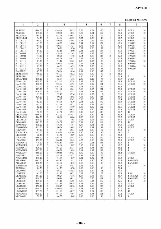
AP30-41
12 340.64 MHz (9)
1 2 3 4 5 6 7 8 9
ALS00002 9 58.37 3.76 1.24 170 1 59.7 9/GR1 10ALS00003 9 58.53 3.77 1.11 167 1 60.0 9/GR2 10ARGINSU4 9 3.40 0.80 19 1 59.9 9/GR3ARGSUR04 9 3.32 1.50 40 1 60.7 9/GR3 10B CE311 9 3.04 2.06 174 1 61.6 8 9/GR7 10B CE312 9 3.44 2.09 174 1 61.0 8 9/GR9 10B CE411 9 3.86 1.38 49 1 62.6 8 9/GR7 10B CE412 9 3.57 1.56 52 1 62.7 8 9/GR9 10B CE511 9 2.44 2.13 104 1 63.0 8 9/GR7 10B NO611 9 2.85 1.69 165 2 62.8 8 9/GR8 10B NO711 9 3.54 1.78 126 2 62.8 8 9/GR8 10B NO811 9 2.37 1.65 73 2 62.8 8 9/GR8B SU111 9 2.76 1.05 50 1 62.8 8 9/GR6 10B SU112 9 2.47 1.48 56 1 62.2 8 9/GR9B SU211 9 3.22 1.36 60 1 62.5 8 9/GR6 10B SU212 9 3.20 1.96 58 1 61.3 8 9/GR9BAHIFRB1 9 24.16 1.81 0.80 142 1 61.6BERBERMU 9 32.32 0.80 0.80 90 2 56.8BERBER02 9 32.32 0.80 0.80 90 1 56.9 2 10BOLAND01 9 2.49 1.27 76 1 67.9 9/GR5CAN01101 9 57.24 3.45 1.27 157 1 59.5 9/GR10 10CAN01201 9 55.95 3.35 0.97 151 1 59.6 9/GR10 10CAN01202 9 55.63 2.74 1.12 32 1 59.6CAN01203 9 55.61 3.08 1.15 151 1 59.5 9/GR12 10CAN01303 9 57.12 3.54 0.91 154 1 60.0 9/GR12 10CAN01304 9 57.36 1.98 1.72 2 1 59.8 9/GR13CAN01403 9 52.02 4.68 0.80 148 1 61.8 9/GR12 10CAN01404 9 52.42 3.10 2.05 152 1 60.4 9/GR13 10CAN01405 9 52.39 2.84 2.29 172 1 60.3 9/GR14 10CAN01504 9 53.77 3.57 1.67 156 1 60.2 9/GR13 10CAN01505 9 53.79 3.30 1.89 162 1 60.1 9/GR14 10CAN01605 9 49.55 2.65 1.40 143 1 60.3 9/GR14 10CAN01606 9 49.55 2.40 1.65 148 1 60.2 10CHLCONT5 9 2.60 0.80 55 1 59.4 9/GR17CHLPAC02 9 1.36 0.80 69 1 59.2 9/GR17CLMAND01 9 5.93 3.85 1.63 114 1 64.9 9/GR5CLM00001 20 9 5.87 3.98 1.96 118 1 63.5 10EQACAND1 9 1.37 0.95 75 1 64.0 9/GR5EQAGAND1 9 0.90 0.81 89 1 61.3 9/GR5FLKANT01 9 3.54 0.80 12 1 59.3 2 10FLKFALKS 9 0.80 0.80 90 1 58.1 2GRD00002 9 12.29 0.80 0.80 90 1 58.8HWA00002 9 23.42 4.20 0.80 160 1 58.8 9/GR1 10HWA00003 9 23.42 4.25 0.80 159 1 58.8 9/GR2 10MEX01NTE 9 26.01 2.89 2.08 155 1 60.5 1MEX01SUR 9 19.82 3.05 2.09 4 1 62.2 1 10MEX02NTE 9 26.31 3.84 1.55 148 1 61.2 1 10MEX02SUR 9 19.88 3.18 1.87 157 1 62.5 1 10PAQPAC01 9 0.80 0.80 90 1 56.2 9/GR17PRG00002 0 9 1.45 1.04 76 1 60.2PRUAND02 9 3.41 1.79 95 1 63.9 9/GR5PTRVIR01 9 18.12 0.80 0.80 90 1 60.5 1 6 9/GR20PTRVIR02 9 18.12 0.80 0.80 90 1 61.0 1 6 9/GR21SPMFRAN3 9 47.51 3.16 0.80 7 1 60.4 2 7 10TRD00001 9 10.70 0.80 0.80 90 1 59.4URG00001 9 1.02 0.89 11 1 60.0USAEH001 9 36.21 5.63 3.33 22 1 61.8 1 5 6 10USAEH002 9 36.16 5.67 3.76 170 1 61.7 1 6 9/GR20 10USAEH003 9 36.11 5.55 3.55 161 1 62.0 1 6 9/GR21 10USAEH004 9 36.05 5.38 3.24 152 1 62.6 1 5 6 10USAPSA02 9 40.58 4.03 0.82 135 1 63.2 9/GR1USAPSA03 9 40.12 3.62 0.80 136 1 65.0 9/GR2USAWH101 9 38.13 5.53 1.95 142 1 62.1 10USAWH102 9 38.57 5.51 1.54 138 1 63.2 10VENAND03 9 6.91 2.37 1.43 111 1 67.2 9/GR5VRG00001 9 18.48 0.80 0.80 90 1 58.3 4
- 509 -
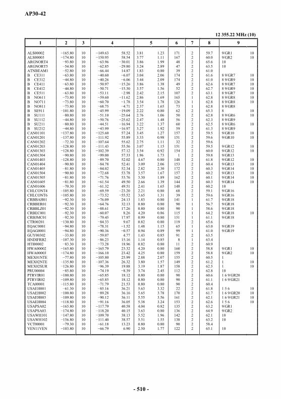
AP30-42
12 355.22 MHz (10)
1 2 3 4 5 6 7 8 9
ALS00002 10 58.52 3.81 1.23 171 2 59.7 9/GR1 10ALS00003 10 58.54 3.77 1.11 167 2 60.0 9/GR2 10ARGNORT4 10 3.86 1.99 48 2 65.6 10ARGNORT5 10 29.80 3.24 2.89 47 2 63.5 10ATNBEAM1 10 14.87 1.83 0.80 39 2 61.0B CE311 10 3.04 2.06 174 2 61.6 8 9/GR7 10B CE312 10 3.44 2.09 174 2 61.0 8 9/GR9 10B CE411 10 3.86 1.38 49 2 62.6 8 9/GR7 10B CE412 10 3.57 1.56 52 2 62.7 8 9/GR9 10B CE511 10 2.42 2.15 107 2 63.1 8 9/GR7 10B NO611 10 2.86 1.69 165 1 62.8 8 9/GR8 10B NO711 10 3.54 1.78 126 1 62.8 8 9/GR8 10B NO811 10 2.37 1.65 73 1 62.8 8 9/GR8B SE911 10 2.22 0.80 62 2 65.3 8 10B SU111 10 2.76 1.06 50 2 62.8 8 9/GR6 10B SU112 10 2.47 1.48 56 2 62.3 8 9/GR9B SU211 10 3.22 1.37 60 2 62.5 8 9/GR6 10B SU212 10 3.27 1.92 59 2 61.3 8 9/GR9CAN01101 10 57.24 3.45 1.27 157 2 59.5 9/GR10 10CAN01201 10 55.89 3.33 0.98 151 2 59.6 9/GR10 10CAN01202 10 55.62 2.75 1.11 32 2 59.6CAN01203 10 55.56 3.07 1.15 151 2 59.5 9/GR12 10CAN01303 10 57.12 3.54 0.92 154 2 60.0 9/GR12 10CAN01304 10 57.33 1.96 1.73 1 2 59.8 9/GR13CAN01403 10 52.02 4.67 0.80 148 2 61.8 9/GR12 10CAN01404 10 52.41 3.09 2.06 153 2 60.4 9/GR13 10CAN01405 10 52.34 2.82 2.30 172 2 60.3 9/GR14 10CAN01504 10 53.78 3.57 1.67 157 2 60.2 9/GR13 10CAN01505 10 53.76 3.30 1.89 162 2 60.1 9/GR14 10CAN01605 10 49.50 2.66 1.39 144 2 60.3 9/GR14 10CAN01606 10 49.51 2.41 1.65 148 2 60.2 10CHLCONT4 10 2.21 0.80 68 2 59.1 9/GR16CHLCONT6 10 3.65 1.31 39 2 59.6 9/GR16CRBBAH01 10 24.13 1.83 0.80 141 1 61.7 9/GR18CRBBER01 10 32.13 0.80 0.80 90 1 56.7 9/GR18CRBBLZ01 10 17.26 0.80 0.80 90 1 58.6 9/GR18CRBEC001 10 8.26 4.20 0.86 115 1 64.2 9/GR18 10CRBJMC01 10 17.97 0.99 0.80 151 1 61.1 9/GR18CTR00201 10 9.67 0.82 0.80 119 2 65.6EQAC0001 10 1.48 1.15 65 1 63.0 9/GR19EQAG0001 10 .36 0.94 0.89 99 1 61.0 9/GR19GUY00302 10 4.77 1.43 0.85 91 2 63.5HNDIFRB2 10 15.16 1.14 0.85 8 1 63.4HTI00002 10 18.96 0.82 0.80 11 2 60.9HWA00002 10 23.32 4.20 0.80 160 2 58.8 9/GR1 10HWA00003 10 23.42 4.25 0.80 159 2 58.8 9/GR2 10MEX01NTE 10 25.99 2.88 2.07 155 2 60.5 1MEX02NTE 10 26.32 3.80 1.57 149 2 61.2 1 10MEX02SUR 10 19.88 3.19 1.87 158 2 62.5 1 10PRU00004 10 3.74 2.45 112 2 62.8 10PTRVIR01 10 18.12 0.80 0.80 90 2 60.6 1 6 9/GR20PTRVIR02 10 18.12 0.80 0.80 90 2 61.1 1 6 9/GR21TCA00001 10 21.53 0.80 0.80 90 2 60.4USAEH001 61.30 10 36.21 5.63 3.32 22 2 61.8 1 5 6 10USAEH002 10 36.16 5.65 3.78 170 2 61.7 1 6 9/GR20 10USAEH003 10 36.11 5.55 3.56 161 2 62.1 1 6 9/GR21 10USAEH004 10 36.05 5.38 3.24 153 2 62.6 1 5 6 10USAPSA02 10 40.58 4.04 0.82 135 2 63.2 9/GR1USAPSA03 10 40.15 3.63 0.80 136 2 64.9 9/GR2USAWH101 10 38.13 5.52 1.96 142 2 62.1 10USAWH102 10 38.57 5.51 1.55 138 2 63.2 10VCT00001 .30 10 13.23 0.80 0.80 90 2 58.4VEN11VEN 10 6.90 2.50 1.77 122 2 65.1 10
- 510 -
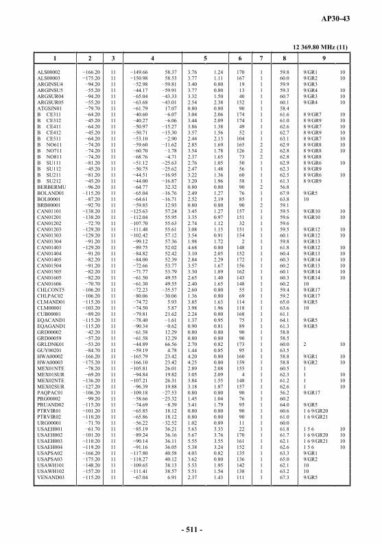
AP30-43
12 369.80 MHz (11)
1 2 3 4 5 6 7 8 9
ALS00002 11 58.37 3.76 1.24 170 1 59.8 9/GR1 10ALS00003 11 58.53 3.77 1.11 167 1 60.0 9/GR2 10ARGINSU4 11 3.40 0.80 19 1 59.9 9/GR3ARGINSU5 11 3.77 0.80 13 1 59.3 9/GR4 10ARGSUR04 11 3.32 1.50 40 1 60.7 9/GR3 10ARGSUR05 11 2.54 2.38 152 1 60.1 9/GR4 10ATGSJN01 11 17.07 0.80 0.80 90 1 58.4B CE311 11 3.04 2.06 174 1 61.6 8 9/GR7 10B CE312 11 3.44 2.09 174 1 61.0 8 9/GR9 10B CE411 11 3.86 1.38 49 1 62.6 8 9/GR7 10B CE412 11 3.57 1.56 52 1 62.7 8 9/GR9 10B CE511 11 2.44 2.13 104 1 63.1 8 9/GR7 10B NO611 11 2.85 1.69 165 2 62.9 8 9/GR8 10B NO711 11 3.54 1.78 126 2 62.8 8 9/GR8 10B NO811 11 2.37 1.65 73 2 62.8 8 9/GR8B SU111 11 2.76 1.05 50 1 62.9 8 9/GR6 10B SU112 11 2.47 1.48 56 1 62.3 8 9/GR9B SU211 11 3.22 1.36 60 1 62.5 8 9/GR6 10B SU212 11 3.20 1.96 58 1 61.3 8 9/GR9BERBERMU 11 32.32 0.80 0.80 90 2 56.8BOLAND01 11 2.49 1.27 76 1 67.9 9/GR5BOL00001 11 2.52 2.19 85 1 63.8 10BRB00001 70 11 12.93 0.80 0.80 90 2 59.1CAN01101 11 57.24 3.45 1.27 157 1 59.5 9/GR10 10CAN01201 11 55.95 3.35 0.97 151 1 59.6 9/GR10 10CAN01202 11 55.63 2.74 1.12 32 1 59.6CAN01203 11 8 55.61 3.08 1.15 151 1 59.5 9/GR12 10CAN01303 11 57.12 3.54 0.91 154 1 60.1 9/GR12 10CAN01304 11 57.36 1.98 1.72 2 1 59.8 9/GR13CAN01403 11 52.02 4.68 0.80 148 1 61.8 9/GR12 10CAN01404 11 52.42 3.10 2.05 152 1 60.4 9/GR13 10CAN01405 11 52.39 2.84 2.29 172 1 60.3 9/GR14 10CAN01504 11 53.77 3.57 1.67 156 1 60.2 9/GR13 10CAN01505 11 53.79 3.30 1.89 162 1 60.1 9/GR14 10CAN01605 11 49.55 2.65 1.40 143 1 60.3 9/GR14 10CAN01606 11 49.55 2.40 1.65 148 1 60.2 10CHLCONT5 11 2.60 0.80 55 1 59.4 9/GR17CHLPAC02 11 1.36 0.80 69 1 59.2 9/GR17CLMAND01 11 5.93 3.85 1.63 114 1 65.0 9/GR5CLM00001 11 5.87 3.98 1.96 118 1 63.6 10CUB00001 11 21.62 2.24 0.80 168 1 61.1EQACAND1 11 1.37 0.95 75 1 64.1 9/GR5EQAGAND1 11 0.90 0.81 89 1 61.3 9/GR5GRD00002 11 12.29 0.80 0.80 90 1 58.8GRD00059 11 12.29 0.80 0.80 90 1 58.5GRLDNK01 11 66.56 2.70 0.82 173 1 60.0 2 10GUY00201 11 4.78 1.44 0.85 95 1 63.5HWA00002 11 79 23.42 4.20 0.80 160 1 58.8 9/GR1 10HWA00003 11 23.42 4.25 0.80 159 1 58.8 9/GR2 10MEX01NTE 11 26.01 2.89 2.08 155 1 60.5 1MEX01SUR 11 19.82 3.05 2.09 4 1 62.3 1 10MEX02NTE 11 26.31 3.84 1.55 148 1 61.2 1 10MEX02SUR 11 19.88 3.18 1.87 157 1 62.6 1 10PAQPAC01 11 0.80 0.80 90 1 56.2 9/GR17PRG00002 11 1.45 1.04 76 1 60.2PRUAND02 11 3.41 1.79 95 1 64.0 9/GR5PTRVIR01 11 18.12 0.80 0.80 90 1 60.6 1 6 9/GR20PTRVIR02 11 18.12 0.80 0.80 90 1 61.0 1 6 9/GR21URG00001 11 1.02 0.89 11 1 60.0USAEH001 11 36.21 5.63 3.33 22 1 61.8 1 5 6 10USAEH002 11 36.16 5.67 3.76 170 1 61.7 1 6 9/GR20 10USAEH003 11 36.11 5.55 3.55 161 1 62.1 1 6 9/GR21 10USAEH004 11 36.05 5.38 3.24 152 1 62.6 1 5 6 10USAPSA02 11 40.58 4.03 0.82 135 1 63.3 9/GR1USAPSA03 11 40.12 3.62 0.80 136 1 65.0 9/GR2USAWH101 11 38.13 5.53 1.95 142 1 62.1 10USAWH102 11 38.57 5.51 1.54 138 1 63.2 10VENAND03 11 6.91 2.37 1.43 111 1 67.3 9/GR5
- 511 -

AP30-44
12 384.38 MHz (12)
1 2 3 4 5 6 7 8 9
ALS00002 12 58.52 3.81 1.23 171 2 59.8 9/GR1 10ALS00003 12 58.54 3.77 1.11 167 2 60.0 9/GR2 10ARGNORT4 12 3.86 1.99 48 2 65.7 10ARGNORT5 12 3.24 2.89 47 2 63.5 10B CE311 12 3.04 2.06 174 2 61.6 8 9/GR7 10B CE312 12 3.44 2.09 174 2 61.0 8 9/GR9 10B CE411 12 3.86 1.38 49 2 62.6 8 9/GR7 10B CE412 12 3.57 1.56 52 2 62.8 8 9/GR9 10B CE511 12 2.42 2.15 107 2 63.1 8 9/GR7 10B NO611 12 2.86 1.69 165 1 62.9 8 9/GR8 10B NO711 12 3.54 1.78 126 1 62.8 8 9/GR8 10B NO811 12 5 2.37 1.65 73 1 62.8 8 9/GR8B SE911 12 2.22 0.80 62 2 65.3 8 10B SU111 12 2.76 1.06 50 2 62.9 8 9/GR6 10B SU112 12 2.47 1.48 56 2 62.3 8 9/GR9B SU211 12 3.22 1.37 60 2 62.5 8 9/GR6 10B SU212 12 3.27 1.92 59 2 61.3 8 9/GR9CAN01101 12 57.24 3.45 1.27 157 2 59.5 9/GR10 10CAN01201 12 55.89 3.33 0.98 151 2 59.6 9/GR10 10CAN01202 12 55.62 2.75 1.11 32 2 59.6CAN01203 12 55.56 3.07 1.15 151 2 59.5 9/GR12 10CAN01303 12 57.12 3.54 0.92 154 2 60.1 9/GR12 10CAN01304 12 57.33 1.96 1.73 1 2 59.8 9/GR13CAN01403 12 52.02 4.67 0.80 148 2 61.8 9/GR12 10CAN01404 12 52.41 3.09 2.06 153 2 60.4 9/GR13 10CAN01405 12 52.34 2.82 2.30 172 2 60.3 9/GR14 10CAN01504 12 53.78 3.57 1.67 157 2 60.2 9/GR13 10CAN01505 12 53.76 3.30 1.89 162 2 60.2 9/GR14 10CAN01605 12 49.50 2.66 1.39 144 2 60.3 9/GR14 10CAN01606 12 49.51 2.41 1.65 148 2 60.2 10CHLCONT4 12 2.21 0.80 68 2 59.1 9/GR16CHLCONT6 12 3.65 1.31 39 2 59.6 9/GR16CRBBAH01 12 24.13 1.83 0.80 141 1 61.7 9/GR18CRBBER01 12 32.13 0.80 0.80 90 1 56.8 9/GR18CRBBLZ01 12 17.26 0.80 0.80 90 1 58.7 9/GR18CRBEC001 12 8.26 4.20 0.86 115 1 64.3 9/GR18 10CRBJMC01 12 17.97 0.99 0.80 151 1 61.1 9/GR18CYM00001 12 19.57 0.80 0.80 90 2 59.6DOMIFRB2 12 18.79 0.98 0.80 167 2 61.1EQAC0001 12 1.48 1.15 65 1 63.0 9/GR19EQAG0001 .80 12 0.94 0.89 99 1 61.0 9/GR19GUFMGG02 12 8.47 4.16 0.81 123 2 62.7 2 7 10HWA00002 12 23.32 4.20 0.80 160 2 58.8 9/GR1 10HWA00003 12 23.42 4.25 0.80 159 2 58.8 9/GR2 10JMC00005 12 18.12 0.80 0.80 90 2 60.6LCAIFRB1 12 13.90 0.80 0.80 90 2 58.4MEX01NTE 12 25.99 2.88 2.07 155 2 60.5 1MEX02NTE 12 26.32 3.80 1.57 149 2 61.2 1 10MEX02SUR 12 19.88 3.19 1.87 158 2 62.5 1 10PRU00004 12 3.74 2.45 112 2 62.9 10PTRVIR01 12 18.12 0.80 0.80 90 2 60.6 1 6 9/GR20PTRVIR02 12 18.12 0.80 0.80 90 2 61.1 1 6 9/GR21SLVIFRB2 12 13.59 0.80 0.80 90 1 61.7USAEH001 12 36.21 5.63 3.32 22 2 61.9 1 5 6 10USAEH002 12 36.16 5.65 3.78 170 2 61.7 1 6 9/GR20 10USAEH003 12 36.11 5.55 3.56 161 2 62.1 1 6 9/GR21 10USAEH004 12 36.05 5.38 3.24 153 2 62.6 1 5 6 10USAPSA02 12 40.58 4.04 0.82 135 2 63.3 9/GR1USAPSA03 12 40.15 3.63 0.80 136 2 65.0 9/GR2USAWH101 12 38.13 5.52 1.96 142 2 62.1 10USAWH102 12 38.57 5.51 1.55 138 2 63.2 10VEN11VEN 12 6.90 2.50 1.77 122 2 65.2 10
- 512 -

AP30-45
12 398.96 MHz (13)
1 2 3 4 5 6 7 8 9
ALS00002 13 58.37 3.76 1.24 170 1 59.7 9/GR1 10ALS00003 13 58.53 3.77 1.11 167 1 60.0 9/GR2 10ARGINSU4 13 3.40 0.80 19 1 59.9 9/GR3ARGSUR04 13 3.32 1.50 40 1 60.7 9/GR3 10B CE311 13 3.04 2.06 174 1 61.6 8 9/GR7 10B CE312 13 3.44 2.09 174 1 61.0 8 9/GR9 10B CE411 13 50.97 3.86 1.38 49 1 62.6 8 9/GR7 10B CE412 13 3.57 1.56 52 1 62.7 8 9/GR9 10B CE511 13 2.44 2.13 104 1 63.0 8 9/GR7 10B NO611 13 2.85 1.69 165 2 62.8 8 9/GR8 10B NO711 13 3.54 1.78 126 2 62.8 8 9/GR8 10B NO811 13 2.37 1.65 73 2 62.8 8 9/GR8B SU111 13 2.76 1.05 50 1 62.8 8 9/GR6 10B SU112 13 2.47 1.48 56 1 62.2 8 9/GR9B SU211 13 1 3.22 1.36 60 1 62.5 8 9/GR6 10B SU212 13 3.20 1.96 58 1 61.3 8 9/GR9BAHIFRB1 13 24.16 1.81 0.80 142 1 61.6BERBERMU 13 32.32 0.80 0.80 90 2 56.8BERBER02 13 32.32 0.80 0.80 90 1 56.9 2 10BOLAND01 13 2.49 1.27 76 1 67.9 9/GR5CAN01101 13 57.24 3.45 1.27 157 1 59.5 9/GR10 10CAN01201 13 55.95 3.35 0.97 151 1 59.6 9/GR10 10CAN01202 13 55.63 2.74 1.12 32 1 59.6CAN01203 13 55.61 3.08 1.15 151 1 59.5 9/GR12 10CAN01303 13 57.12 3.54 0.91 154 1 60.0 9/GR12 10CAN01304 13 57.36 1.98 1.72 2 1 59.8 9/GR13CAN01403 13 52.02 4.68 0.80 148 1 61.8 9/GR12 10CAN01404 13 52.42 3.10 2.05 152 1 60.4 9/GR13 10CAN01405 13 52.39 2.84 2.29 172 1 60.3 9/GR14 10CAN01504 13 53.77 3.57 1.67 156 1 60.2 9/GR13 10CAN01505 13 53.79 3.30 1.89 162 1 60.1 9/GR14 10CAN01605 13 49.55 2.65 1.40 143 1 60.3 9/GR14 10CAN01606 13 49.55 2.40 1.65 148 1 60.2 10CHLCONT5 13 2.60 0.80 55 1 59.4 9/GR17CHLPAC02 13 1.36 0.80 69 1 59.2 9/GR17CLMAND01 13 5.93 3.85 1.63 114 1 64.9 9/GR5CLM00001 13 5.87 3.98 1.96 118 1 63.5 10EQACAND1 13 1.37 0.95 75 1 64.0 9/GR5EQAGAND1 13 0.90 0.81 89 1 61.3 9/GR5FLKANT01 .20 13 3.54 0.80 12 1 59.3 2 10FLKFALKS 13 0.80 0.80 90 1 58.1 2GRD00002 13 12.29 0.80 0.80 90 1 58.8HWA00002 13 23.42 4.20 0.80 160 1 58.8 9/GR1 10HWA00003 13 23.42 4.25 0.80 159 1 58.8 9/GR2 10MEX01NTE 13 26.01 2.89 2.08 155 1 60.5 1MEX01SUR 13 19.82 3.05 2.09 4 1 62.2 1 10MEX02NTE 13 26.31 3.84 1.55 148 1 61.2 1 10MEX02SUR 13 19.88 3.18 1.87 157 1 62.5 1 10PAQPAC01 13 0.80 0.80 90 1 56.2 9/GR17PRG00002 13 1.45 1.04 76 1 60.2PRUAND02 13 3.41 1.79 95 1 63.9 9/GR5PTRVIR01 13 18.12 0.80 0.80 90 1 60.5 1 6 9/GR20PTRVIR02 13 18.12 0.80 0.80 90 1 61.0 1 6 9/GR21SPMFRAN3 13 47.51 3.16 0.80 7 1 60.4 2 7 10TRD00001 13 10.70 0.80 0.80 90 1 59.4URG00001 13 1.02 0.89 11 1 60.0USAEH001 13 36.21 5.63 3.33 22 1 61.8 1 5 6 10USAEH002 13 36.16 5.67 3.76 170 1 61.7 1 6 9/GR20 10USAEH003 13 36.11 5.55 3.55 161 1 62.0 1 6 9/GR21 10USAEH004 13 36.05 5.38 3.24 152 1 62.6 1 5 6 10USAPSA02 13 40.58 4.03 0.82 135 1 63.2 9/GR1USAPSA03 13 40.12 3.62 0.80 136 1 65.0 9/GR2USAWH101 13 38.13 5.53 1.95 142 1 62.1 10USAWH102 13 38.57 5.51 1.54 138 1 63.2 10VENAND03 13 6.91 2.37 1.43 111 1 67.2 9/GR5VRG00001 13 18.48 0.80 0.80 90 1 58.3 4
- 513 -

AP30-46
12 413.54 MHz (14)
1 2 3 4 5 6 7 8 9
ALS00002 14 58.52 3.81 1.23 171 2 59.7 9/GR1 10ALS00003 14 58.54 3.77 1.11 167 2 60.0 9/GR2 10ARGNORT4 14 3.86 1.99 48 2 65.6 10ARGNORT5 14 3.24 2.89 47 2 63.5 10ATNBEAM1 14 14.87 1.83 0.80 39 2 61.0B CE311 14 3.04 2.06 174 2 61.6 8 9/GR7 10B CE312 14 3.44 2.09 174 2 61.0 8 9/GR9 10B CE411 14 3.86 1.38 49 2 62.6 8 9/GR7 10B CE412 14 3.57 1.56 52 2 62.7 8 9/GR9 10B CE511 14 2.42 2.15 107 2 63.1 8 9/GR7 10B NO611 14 2.86 1.69 165 1 62.8 8 9/GR8 10B NO711 14 3.54 1.78 126 1 62.8 8 9/GR8 10B NO811 14 2.37 1.65 73 1 62.8 8 9/GR8B SE911 14 2.22 0.80 62 2 65.3 8 10B SU111 14 2.76 1.06 50 2 62.8 8 9/GR6 10B SU112 14 2.47 1.48 56 2 62.3 8 9/GR9B SU211 14 3.22 1.37 60 2 62.5 8 9/GR6 10B SU212 14 3.27 1.92 59 2 61.3 8 9/GR9CAN01101 137.80 14 57.24 3.45 1.27 157 2 59.5 9/GR10 10CAN01201 14 55.89 3.33 0.98 151 2 59.6 9/GR10 10CAN01202 14 55.62 2.75 1.11 32 2 59.6CAN01203 14 55.56 3.07 1.15 151 2 59.5 9/GR12 10CAN01303 8.80 14 57.12 3.54 0.92 154 2 60.0 9/GR12 10CAN01304 14 57.33 1.96 1.73 1 2 59.8 9/GR13CAN01403 14 52.02 4.67 0.80 148 2 61.8 9/GR12 10CAN01404 14 52.41 3.09 2.06 153 2 60.4 9/GR13 10CAN01405 80 14 52.34 2.82 2.30 172 2 60.3 9/GR14 10CAN01504 14 53.78 3.57 1.67 157 2 60.2 9/GR13 10CAN01505 14 53.76 3.30 1.89 162 2 60.1 9/GR14 10CAN01605 14 49.50 2.66 1.39 144 2 60.3 9/GR14 10CAN01606 30 14 49.51 2.41 1.65 148 2 60.2 10CHLCONT4 14 2.21 0.80 68 2 59.1 9/GR16CHLCONT6 14 3.65 1.31 39 2 59.6 9/GR16CRBBAH01 14 24.13 1.83 0.80 141 1 61.7 9/GR18CRBBER01 14 76 32.13 0.80 0.80 90 1 56.7 9/GR18CRBBLZ01 14 17.26 0.80 0.80 90 1 58.6 9/GR18CRBEC001 14 8.26 4.20 0.86 115 1 64.2 9/GR18 10CRBJMC01 14 17.97 0.99 0.80 151 1 61.1 9/GR18CTR00201 14 9.67 0.82 0.80 119 2 65.6EQAC0001 14 1.48 1.15 65 1 63.0 9/GR19EQAG0001 14 0.94 0.89 99 1 61.0 9/GR19GUY00302 14 4.77 1.43 0.85 91 2 63.5HNDIFRB2 14 15.16 1.14 0.85 8 1 63.4HTI00002 14 18.96 0.82 0.80 11 2 60.9HWA00002 14 23.32 4.20 0.80 160 2 58.8 9/GR1 10HWA00003 14 23.42 4.25 0.80 159 2 58.8 9/GR2 10MEX01NTE 14 25.99 2.88 2.07 155 2 60.5 1MEX02NTE 80 14 26.32 3.80 1.57 149 2 61.2 1 10MEX02SUR 14 19.88 3.19 1.87 158 2 62.5 1 10PRU00004 14 3.74 2.45 112 2 62.8 10PTRVIR01 14 18.12 0.80 0.80 90 2 60.6 1 6 9/GR20PTRVIR02 14 5 18.12 0.80 0.80 90 2 61.1 1 6 9/GR21TCA00001 14 21.53 0.80 0.80 90 2 60.4USAEH001 14 36.21 5.63 3.32 22 2 61.8 1 5 6 10USAEH002 14 36.16 5.65 3.78 170 2 61.7 1 6 9/GR20 10USAEH003 14 36.11 5.55 3.56 161 2 62.1 1 6 9/GR21 10USAEH004 14 36.05 5.38 3.24 153 2 62.6 1 5 6 10USAPSA02 14 40.58 4.04 0.82 135 2 63.2 9/GR1USAPSA03 14 40.15 3.63 0.80 136 2 64.9 9/GR2USAWH101 14 70 38.13 5.52 1.96 142 2 62.1 10USAWH102 14 38.57 5.51 1.55 138 2 63.2 10VCT00001 14 13.23 0.80 0.80 90 2 58.4VEN11VEN 14 6.90 2.50 1.77 122 2 65.1 10
- 514 -

AP30-47
12 428.12 MHz (15)
1 2 3 4 5 6 7 8 9
ALS00002 15 58.37 3.76 1.24 170 1 59.8 9/GR1 10ALS00003 15 58.53 3.77 1.11 167 1 60.0 9/GR2 10ARGINSU4 15 3.40 0.80 19 1 59.9 9/GR3ARGINSU5 15 3.77 0.80 13 1 59.3 9/GR4 10ARGSUR04 15 3.32 1.50 40 1 60.7 9/GR3 10ARGSUR05 15 2.54 2.38 152 1 60.1 9/GR4 10ATGSJN01 15 17.07 0.80 0.80 90 1 58.4B CE311 15 3.04 2.06 174 1 61.6 8 9/GR7 10B CE312 .20 15 3.44 2.09 174 1 61.0 8 9/GR9 10B CE411 15 3.86 1.38 49 1 62.6 8 9/GR7 10B CE412 15 3.57 1.56 52 1 62.7 8 9/GR9 10B CE511 15 2.44 2.13 104 1 63.1 8 9/GR7 10B NO611 .20 15 2.85 1.69 165 2 62.9 8 9/GR8 10B NO711 15 3.54 1.78 126 2 62.8 8 9/GR8 10B NO811 15 2.37 1.65 73 2 62.8 8 9/GR8B SU111 15 2.76 1.05 50 1 62.9 8 9/GR6 10B SU112 0 15 2.47 1.48 56 1 62.3 8 9/GR9B SU211 15 3.22 1.36 60 1 62.5 8 9/GR6 10B SU212 15 3.20 1.96 58 1 61.3 8 9/GR9BERBERMU 15 32.32 0.80 0.80 90 2 56.8BOLAND01 15 2.49 1.27 76 1 67.9 9/GR5BOL00001 15 2.52 2.19 85 1 63.8 10BRB00001 15 12.93 0.80 0.80 90 2 59.1CAN01101 15 57.24 3.45 1.27 157 1 59.5 9/GR10 10CAN01201 15 55.95 3.35 0.97 151 1 59.6 9/GR10 10CAN01202 15 55.63 2.74 1.12 32 1 59.6CAN01203 15 55.61 3.08 1.15 151 1 59.5 9/GR12 10CAN01303 15 57.12 3.54 0.91 154 1 60.1 9/GR12 10CAN01304 15 57.36 1.98 1.72 2 1 59.8 9/GR13CAN01403 15 52.02 4.68 0.80 148 1 61.8 9/GR12 10CAN01404 15 52.42 3.10 2.05 152 1 60.4 9/GR13 10CAN01405 15 52.39 2.84 2.29 172 1 60.3 9/GR14 10CAN01504 15 53.77 3.57 1.67 156 1 60.2 9/GR13 10CAN01505 15 53.79 3.30 1.89 162 1 60.1 9/GR14 10CAN01605 15 49.55 2.65 1.40 143 1 60.3 9/GR14 10CAN01606 15 49.55 2.40 1.65 148 1 60.2 10CHLCONT5 15 2.60 0.80 55 1 59.4 9/GR17CHLPAC02 15 1.36 0.80 69 1 59.2 9/GR17CLMAND01 15 5.93 3.85 1.63 114 1 65.0 9/GR5CLM00001 15 5.87 3.98 1.96 118 1 63.6 10CUB00001 15 21.62 2.24 0.80 168 1 61.1EQACAND1 15 1.37 0.95 75 1 64.1 9/GR5EQAGAND1 15 0.90 0.81 89 1 61.3 9/GR5GRD00002 15 12.29 0.80 0.80 90 1 58.8GRD00059 15 12.29 0.80 0.80 90 1 58.5GRLDNK01 15 66.56 2.70 0.82 173 1 60.0 2 10GUY00201 15 4.78 1.44 0.85 95 1 63.5HWA00002 15 23.42 4.20 0.80 160 1 58.8 9/GR1 10HWA00003 15 23.42 4.25 0.80 159 1 58.8 9/GR2 10MEX01NTE 15 26.01 2.89 2.08 155 1 60.5 1MEX01SUR 15 19.82 3.05 2.09 4 1 62.3 1 10MEX02NTE 15 26.31 3.84 1.55 148 1 61.2 1 10MEX02SUR 15 19.88 3.18 1.87 157 1 62.6 1 10PAQPAC01 15 0.80 0.80 90 1 56.2 9/GR17PRG00002 15 1.45 1.04 76 1 60.2PRUAND02 15 3.41 1.79 95 1 64.0 9/GR5PTRVIR01 15 18.12 0.80 0.80 90 1 60.6 1 6 9/GR20PTRVIR02 15 18.12 0.80 0.80 90 1 61.0 1 6 9/GR21URG00001 15 1.02 0.89 11 1 60.0USAEH001 15 36.21 5.63 3.33 22 1 61.8 1 5 6 10USAEH002 15 36.16 5.67 3.76 170 1 61.7 1 6 9/GR20 10USAEH003 15 36.11 5.55 3.55 161 1 62.1 1 6 9/GR21 10USAEH004 15 36.05 5.38 3.24 152 1 62.6 1 5 6 10USAPSA02 15 40.58 4.03 0.82 135 1 63.3 9/GR1USAPSA03 15 40.12 3.62 0.80 136 1 65.0 9/GR2USAWH101 15 38.13 5.53 1.95 142 1 62.1 10USAWH102 .20 15 38.57 5.51 1.54 138 1 63.2 10VENAND03 15 6.91 2.37 1.43 111 1 67.3 9/GR5
- 515 -

AP30-48
12 442.70 MHz (16)
1 2 3 4 5 6 7 8 9
ALS00002 16 58.52 3.81 1.23 171 2 59.8 9/GR1 10ALS00003 16 58.54 3.77 1.11 167 2 60.0 9/GR2 10ARGNORT4 16 3.86 1.99 48 2 65.7 10ARGNORT5 16 3.24 2.89 47 2 63.5 10B CE311 16 3.04 2.06 174 2 61.6 8 9/GR7 10B CE312 16 3.44 2.09 174 2 61.0 8 9/GR9 10B CE411 16 3.86 1.38 49 2 62.6 8 9/GR7 10B CE412 16 3.57 1.56 52 2 62.8 8 9/GR9 10B CE511 16 2.42 2.15 107 2 63.1 8 9/GR7 10B NO611 16 2.86 1.69 165 1 62.9 8 9/GR8 10B NO711 16 3.54 1.78 126 1 62.8 8 9/GR8 10B NO811 16 2.37 1.65 73 1 62.8 8 9/GR8B SE911 16 2.22 0.80 62 2 65.3 8 10B SU111 16 2.76 1.06 50 2 62.9 8 9/GR6 10B SU112 16 2.47 1.48 56 2 62.3 8 9/GR9B SU211 16 3.22 1.37 60 2 62.5 8 9/GR6 10B SU212 16 3.27 1.92 59 2 61.3 8 9/GR9CAN01101 16 57.24 3.45 1.27 157 2 59.5 9/GR10 10CAN01201 16 55.89 3.33 0.98 151 2 59.6 9/GR10 10CAN01202 16 55.62 2.75 1.11 32 2 59.6CAN01203 16 55.56 3.07 1.15 151 2 59.5 9/GR12 10CAN01303 16 57.12 3.54 0.92 154 2 60.1 9/GR12 10CAN01304 16 57.33 1.96 1.73 1 2 59.8 9/GR13CAN01403 16 52.02 4.67 0.80 148 2 61.8 9/GR12 10CAN01404 16 52.41 3.09 2.06 153 2 60.4 9/GR13 10CAN01405 16 52.34 2.82 2.30 172 2 60.3 9/GR14 10CAN01504 16 53.78 3.57 1.67 157 2 60.2 9/GR13 10CAN01505 16 53.76 3.30 1.89 162 2 60.2 9/GR14 10CAN01605 16 49.50 2.66 1.39 144 2 60.3 9/GR14 10CAN01606 16 49.51 2.41 1.65 148 2 60.2 10CHLCONT4 16 2.21 0.80 68 2 59.1 9/GR16CHLCONT6 16 3.65 1.31 39 2 59.6 9/GR16CRBBAH01 16 24.13 1.83 0.80 141 1 61.7 9/GR18CRBBER01 16 32.13 0.80 0.80 90 1 56.8 9/GR18CRBBLZ01 16 17.26 0.80 0.80 90 1 58.7 9/GR18CRBEC001 16 8.26 4.20 0.86 115 1 64.3 9/GR18 10CRBJMC01 16 17.97 0.99 0.80 151 1 61.1 9/GR18CYM00001 16 19.57 0.80 0.80 90 2 59.6DOMIFRB2 16 .51 18.79 0.98 0.80 167 2 61.1EQAC0001 16 1.48 1.15 65 1 63.0 9/GR19EQAG0001 16 0.94 0.89 99 1 61.0 9/GR19GUFMGG02 16 8.47 4.16 0.81 123 2 62.7 2 7 10HWA00002 16 23.32 4.20 0.80 160 2 58.8 9/GR1 10HWA00003 16 23.42 4.25 0.80 159 2 58.8 9/GR2 10JMC00005 16 18.12 0.80 0.80 90 2 60.6LCAIFRB1 16 13.90 0.80 0.80 90 2 58.4MEX01NTE 16 25.99 2.88 2.07 155 2 60.5 1MEX02NTE 16 26.32 3.80 1.57 149 2 61.2 1 10MEX02SUR 16 19.88 3.19 1.87 158 2 62.5 1 10PRU00004 16 3.74 2.45 112 2 62.9 10PTRVIR01 16 18.12 0.80 0.80 90 2 60.6 1 6 9/GR20PTRVIR02 16 18.12 0.80 0.80 90 2 61.1 1 6 9/GR21SLVIFRB2 16 13.59 0.80 0.80 90 1 61.7USAEH001 16 36.21 5.63 3.32 22 2 61.9 1 5 6 10USAEH002 16 36.16 5.65 3.78 170 2 61.7 1 6 9/GR20 10USAEH003 9.80 16 36.11 5.55 3.56 161 2 62.1 1 6 9/GR21 10USAEH004 16 36.05 5.38 3.24 153 2 62.6 1 5 6 10USAPSA02 16 40.58 4.04 0.82 135 2 63.3 9/GR1USAPSA03 16 40.15 3.63 0.80 136 2 65.0 9/GR2USAWH101 16 38.13 5.52 1.96 142 2 62.1 10USAWH102 16 38.57 5.51 1.55 138 2 63.2 10VEN11VEN 16 6.90 2.50 1.77 122 2 65.2 10
- 516 -
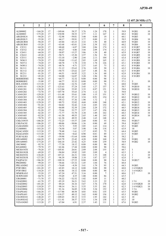
AP30-49
12 457.28 MHz (17)
1 2 3 4 5 6 7 8 9
ALS00002 17 58.37 3.76 1.24 170 1 59.9 9/GR1 10ALS00003 17 58.53 3.77 1.11 167 1 60.2 9/GR2 10ARGINSU4 17 3.40 0.80 19 1 60.1 9/GR3ARGINSU5 17 3.77 0.80 13 1 59.5 9/GR4 10ARGSUR04 17 3.32 1.50 40 1 60.9 9/GR3 10ARGSUR05 17 2.54 2.38 152 1 60.2 9/GR4 10B CE311 17 3.04 2.06 174 1 61.9 8 9/GR7 10B CE312 17 3.44 2.09 174 1 61.2 8 9/GR9 10B CE411 17 3.86 1.38 49 1 62.9 8 9/GR7 10B CE412 17 3.57 1.56 52 1 63.0 8 9/GR9 10B CE511 17 2.44 2.13 104 1 63.4 8 9/GR7 10B NO611 17 2.85 1.69 165 2 63.1 8 9/GR8 10B NO711 17 3.54 1.78 126 2 63.1 8 9/GR8 10B NO811 17 2.37 1.65 73 2 63.1 8 9/GR8B SU111 17 2.76 1.05 50 1 63.2 8 9/GR6 10B SU112 17 2.47 1.48 56 1 62.5 8 9/GR9B SU211 17 3.22 1.36 60 1 62.8 8 9/GR6 10B SU212 17 3.20 1.96 58 1 61.6 8 9/GR9BERBERMU 17 32.32 0.80 0.80 90 2 57.0BERBER02 17 32.32 0.80 0.80 90 1 57.1 2 10BOLAND01 17 2.49 1.27 76 1 68.0 9/GR5CAN01101 17 57.24 3.45 1.27 157 1 59.7 9/GR10 10CAN01201 17 55.95 3.35 0.97 151 1 59.8 9/GR10 10CAN01202 17 55.63 2.74 1.12 32 1 59.8CAN01203 17 55.61 3.08 1.15 151 1 59.7 9/GR12 10CAN01303 17 57.12 3.54 0.91 154 1 60.2 9/GR12 10CAN01304 17 57.36 1.98 1.72 2 1 60.0 9/GR13CAN01403 17 52.02 4.68 0.80 148 1 62.1 9/GR12 10CAN01404 17 52.42 3.10 2.05 152 1 60.6 9/GR13 10CAN01405 17 52.39 2.84 2.29 172 1 60.5 9/GR14 10CAN01504 17 53.77 3.57 1.67 156 1 60.4 9/GR13 10CAN01505 17 53.79 3.30 1.89 162 1 60.3 9/GR14 10CAN01605 17 49.55 2.65 1.40 143 1 60.5 9/GR14 10CAN01606 17 49.55 2.40 1.65 148 1 60.4 10CHLCONT5 17 2.60 0.80 55 1 59.6 9/GR17CHLPAC02 17 1.36 0.80 69 1 59.4 9/GR17CLMAND01 17 5.93 3.85 1.63 114 1 65.3 9/GR5CLM00001 20 17 5.87 3.98 1.96 118 1 63.9 10EQACAND1 17 1.37 0.95 75 1 64.4 9/GR5EQAGAND1 17 0.90 0.81 89 1 61.5 9/GR5FLKFALKS 17 0.80 0.80 90 1 58.2 2HWA00002 17 23.42 4.20 0.80 160 1 59.0 9/GR1 10HWA00003 17 23.42 4.25 0.80 159 1 58.9 9/GR2 10JMC00002 17 18.12 0.80 0.80 90 2 60.1KNA00001 79.70 17 62.46 17.44 0.80 0.80 90 1 58.6MEX01NTE 17 26.01 2.89 2.08 155 1 60.7 1MEX01SUR 17 19.82 3.05 2.09 4 1 62.5 1 10MEX02NTE 17 26.31 3.84 1.55 148 1 61.4 1 10MEX02SUR 17 19.88 3.18 1.87 157 1 62.8 1 10PAQPAC01 17 0.80 0.80 90 1 56.4 9/GR17PRG00002 17 1.45 1.04 76 1 60.4PRUAND02 17 3.41 1.79 95 1 64.3 9/GR5PTRVIR01 17 18.12 0.80 0.80 90 1 60.8 1 6 9/GR20PTRVIR02 17 18.12 0.80 0.80 90 1 61.3 1 6 9/GR21SPMFRAN3 .20 17 47.51 3.16 0.80 7 1 60.6 2 7 10SURINAM2 17 4.35 1.00 0.80 86 1 63.5URG00001 17 1.02 0.89 11 1 60.2USAEH001 17 36.21 5.63 3.33 22 1 62.1 1 5 6 10USAEH002 17 36.16 5.67 3.76 170 1 62.0 1 6 9/GR20 10USAEH003 17 36.11 5.55 3.55 161 1 62.3 1 6 9/GR21 10USAEH004 17 36.05 5.38 3.24 152 1 62.9 1 5 6 10USAPSA02 17 40.58 4.03 0.82 135 1 63.5 9/GR1USAPSA03 17 40.12 3.62 0.80 136 1 65.3 9/GR2USAWH101 17 38.13 5.53 1.95 142 1 62.3 10USAWH102 17 38.57 5.51 1.54 138 1 63.5 10VENAND03 17 6.91 2.37 1.43 111 1 67.6 9/GR5
- 517 -
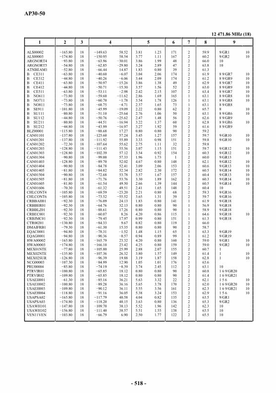
AP30-50
12 471.86 MHz (18)
1 2 3 4 5 6 7 8 9
ALS00002 18 58.52 3.81 1.23 171 2 59.9 9/GR1 10ALS00003 18 58.54 3.77 1.11 167 2 60.2 9/GR2 10ARGNORT4 18 3.86 1.99 48 2 66.0 10ARGNORT5 18 3.24 2.89 47 2 63.8 10ATNBEAM1 18 14.87 1.83 0.80 39 2 61.3B CE311 18 3.04 2.06 174 2 61.9 8 9/GR7 10B CE312 18 3.44 2.09 174 2 61.2 8 9/GR9 10B CE411 18 3.86 1.38 49 2 62.9 8 9/GR7 10B CE412 4.80 18 3.57 1.56 52 2 63.0 8 9/GR9 10B CE511 18 2.42 2.15 107 2 63.4 8 9/GR7 10B NO611 18 2.86 1.69 165 1 63.1 8 9/GR8 10B NO711 18 3.54 1.78 126 1 63.1 8 9/GR8 10B NO811 73.80 18 2.37 1.65 73 1 63.1 8 9/GR8B SE911 18 2.22 0.80 62 2 65.7 8 10B SU111 18 2.76 1.06 50 2 63.1 8 9/GR6 10B SU112 18 2.47 1.48 56 2 62.6 8 9/GR9B SU211 18 44.51 3.22 1.37 60 2 62.8 8 9/GR6 10B SU212 18 3.27 1.92 59 2 61.6 8 9/GR9BLZ00001 18 17.27 0.80 0.80 90 2 59.2CAN01101 18 57.24 3.45 1.27 157 2 59.7 9/GR10 10CAN01201 18 55.89 3.33 0.98 151 2 59.8 9/GR10 10CAN01202 18 55.62 2.75 1.11 32 2 59.8CAN01203 18 55.56 3.07 1.15 151 2 59.7 9/GR12 10CAN01303 18 57.12 3.54 0.92 154 2 60.3 9/GR12 10CAN01304 18 57.33 1.96 1.73 1 2 60.0 9/GR13CAN01403 18 52.02 4.67 0.80 148 2 62.1 9/GR12 10CAN01404 18 52.41 3.09 2.06 153 2 60.6 9/GR13 10CAN01405 18 52.34 2.82 2.30 172 2 60.5 9/GR14 10CAN01504 18 53.78 3.57 1.67 157 2 60.4 9/GR13 10CAN01505 18 53.76 3.30 1.89 162 2 60.3 9/GR14 10CAN01605 18 49.50 2.66 1.39 144 2 60.5 9/GR14 10CAN01606 18 49.51 2.41 1.65 148 2 60.4 10CHLCONT4 18 2.21 0.80 68 2 59.3 9/GR16CHLCONT6 18 3.65 1.31 39 2 59.7 9/GR16CRBBAH01 18 24.13 1.83 0.80 141 1 61.9 9/GR18CRBBER01 18 32.13 0.80 0.80 90 1 56.9 9/GR18CRBBLZ01 18 17.26 0.80 0.80 90 1 58.9 9/GR18CRBEC001 18 8.26 4.20 0.86 115 1 64.6 9/GR18 10CRBJMC01 18 17.97 0.99 0.80 151 1 61.3 9/GR18CTR00201 18 9.67 0.82 0.80 119 2 66.0DMAIFRB1 18 15.35 0.80 0.80 90 2 58.7EQAC0001 18 1.48 1.15 65 1 63.3 9/GR19EQAG0001 18 0.94 0.89 99 1 61.2 9/GR19HWA00002 18 23.32 4.20 0.80 160 2 59.0 9/GR1 10HWA00003 18 23.42 4.25 0.80 159 2 59.0 9/GR2 10MEX01NTE 18 25.99 2.88 2.07 155 2 60.7 1MEX02NTE 18 26.32 3.80 1.57 149 2 61.4 1 10MEX02SUR 18 19.88 3.19 1.87 158 2 62.8 1 10NCG00003 18 12.90 1.05 1.01 176 1 63.6PRU00004 18 .39 3.74 2.45 112 2 63.1 10PTRVIR01 18 18.12 0.80 0.80 90 2 60.8 1 6 9/GR20PTRVIR02 18 18.12 0.80 0.80 90 2 61.4 1 6 9/GR21USAEH001 18 36.21 5.63 3.32 22 2 62.1 1 5 6 10USAEH002 18 36.16 5.65 3.78 170 2 62.0 1 6 9/GR20 10USAEH003 18 36.11 5.55 3.56 161 2 62.3 1 6 9/GR21 10USAEH004 18 36.05 5.38 3.24 153 2 62.9 1 5 6 10USAPSA02 18 40.58 4.04 0.82 135 2 63.5 9/GR1USAPSA03 18 8.20 40.15 3.63 0.80 136 2 65.3 9/GR2USAWH101 18 38.13 5.52 1.96 142 2 62.3 10USAWH102 18 38.57 5.51 1.55 138 2 63.5 10VEN11VEN 18 6.90 2.50 1.77 122 2 65.5 10
- 518 -

AP30-51
12 486.44 MHz (19)
1 2 3 4 5 6 7 8 9
ALS00002 19 58.37 3.76 1.24 170 1 60.0 9/GR1 10ALS00003 19 58.53 3.77 1.11 167 1 60.2 9/GR2 10ARGINSU4 19 3.40 0.80 19 1 60.1 9/GR3ARGINSU5 19 3.77 0.80 13 1 59.5 9/GR4 10ARGSUR04 19 3.32 1.50 40 1 60.9 9/GR3 10ARGSUR05 19 2.54 2.38 152 1 60.3 9/GR4 10B CE311 19 3.04 2.06 174 1 61.9 8 9/GR7 10B CE312 19 3.44 2.09 174 1 61.3 8 9/GR9 10B CE411 19 3.86 1.38 49 1 62.9 8 9/GR7 10B CE412 19 3.57 1.56 52 1 63.1 8 9/GR9 10B CE511 19 2.44 2.13 104 1 63.4 8 9/GR7 10B NO611 19 2.85 1.69 165 2 63.2 8 9/GR8 10B NO711 19 3.54 1.78 126 2 63.2 8 9/GR8 10B NO811 19 2.37 1.65 73 2 63.1 8 9/GR8B SU111 19 2.76 1.05 50 1 63.2 8 9/GR6 10B SU112 19 2.47 1.48 56 1 62.6 8 9/GR9B SU211 19 3.22 1.36 60 1 62.8 8 9/GR6 10B SU212 19 3.20 1.96 58 1 61.6 8 9/GR9BERBERMU 19 32.32 0.80 0.80 90 2 57.0BOLAND01 19 2.49 1.27 76 1 68.1 9/GR5BOL00001 19 2.52 2.19 85 1 64.2 10BRB00001 19 12.93 0.80 0.80 90 2 59.4CAN01101 19 57.24 3.45 1.27 157 1 59.7 9/GR10 10CAN01201 19 55.95 3.35 0.97 151 1 59.8 9/GR10 10CAN01202 19 107.70 55.63 2.74 1.12 32 1 59.8CAN01203 19 55.61 3.08 1.15 151 1 59.7 9/GR12 10CAN01303 19 57.12 3.54 0.91 154 1 60.3 9/GR12 10CAN01304 19 57.36 1.98 1.72 2 1 60.1 9/GR13CAN01403 19 52.02 4.68 0.80 148 1 62.1 9/GR12 10CAN01404 19 52.42 3.10 2.05 152 1 60.6 9/GR13 10CAN01405 19 52.39 2.84 2.29 172 1 60.5 9/GR14 10CAN01504 19 53.77 3.57 1.67 156 1 60.4 9/GR13 10CAN01505 19 53.79 3.30 1.89 162 1 60.4 9/GR14 10CAN01605 19 49.55 2.65 1.40 143 1 60.5 9/GR14 10CAN01606 19 49.55 2.40 1.65 148 1 60.5 10CHLCONT5 19 2.60 0.80 55 1 59.6 9/GR17CHLPAC02 19 1.36 0.80 69 1 59.4 9/GR17CLMAND01 19 5.93 3.85 1.63 114 1 65.4 9/GR5CLM00001 19 5.87 3.98 1.96 118 1 63.9 10CUB00001 19 21.62 2.24 0.80 168 1 61.3EQACAND1 19 1.37 0.95 75 1 64.4 9/GR5EQAGAND1 19 0.90 0.81 89 1 61.6 9/GR5GRD00059 19 12.29 0.80 0.80 90 1 58.7GRLDNK01 19 66.56 2.70 0.82 173 1 60.2 2 10GUY00201 19 4.78 1.44 0.85 95 1 63.8HWA00002 19 23.42 4.20 0.80 160 1 59.0 9/GR1 10HWA00003 19 23.42 4.25 0.80 159 1 59.0 9/GR2 10MEX01NTE 19 26.01 2.89 2.08 155 1 60.8 1MEX01SUR 19 19.82 3.05 2.09 4 1 62.5 1 10MEX02NTE 19 26.31 3.84 1.55 148 1 61.5 1 10MEX02SUR 19 19.88 3.18 1.87 157 1 62.8 1 10MSR00001 19 16.75 0.80 0.80 90 1 58.9 4PAQPAC01 19 0.80 0.80 90 1 56.4 9/GR17PRG00002 19 1.45 1.04 76 1 60.5PRUAND02 19 3.41 1.79 95 1 64.3 9/GR5PTRVIR01 19 18.12 0.80 0.80 90 1 60.8 1 6 9/GR20PTRVIR02 19 18.12 0.80 0.80 90 1 61.3 1 6 9/GR21URG00001 19 1.02 0.89 11 1 60.2USAEH001 19 36.21 5.63 3.33 22 1 62.1 1 5 6 10USAEH002 19 36.16 5.67 3.76 170 1 62.0 1 6 9/GR20 10USAEH003 19 36.11 5.55 3.55 161 1 62.4 1 6 9/GR21 10USAEH004 19 36.05 5.38 3.24 152 1 62.9 1 5 6 10USAPSA02 19 40.58 4.03 0.82 135 1 63.6 9/GR1USAPSA03 19 40.12 3.62 0.80 136 1 65.4 9/GR2USAWH101 19 38.13 5.53 1.95 142 1 62.4 10USAWH102 19 38.57 5.51 1.54 138 1 63.5 10VENAND03 19 6.91 2.37 1.43 111 1 67.7 9/GR5
- 519 -

AP30-52
12 501.02 MHz (20)
1 2 3 4 5 6 7 8 9
ALS00002 20 58.52 3.81 1.23 171 2 59.9 9/GR1 10ALS00003 20 58.54 3.77 1.11 167 2 60.2 9/GR2 10ARGNORT4 80 20 3.86 1.99 48 2 66.1 10ARGNORT5 20 3.24 2.89 47 2 63.9 10B CE311 20 3.04 2.06 174 2 61.9 8 9/GR7 10B CE312 20 3.44 2.09 174 2 61.3 8 9/GR9 10 11B CE411 20 0.97 3.86 1.38 49 2 62.9 8 9/GR7 10B CE412 20 3.57 1.56 52 2 63.1 8 9/GR9 10 12B CE511 20 2.42 2.15 107 2 63.4 8 9/GR7 10B NO611 20 2.86 1.69 165 1 63.2 8 9/GR8 10B NO711 20 3.54 1.78 126 1 63.2 8 9/GR8 10B NO811 20 2.37 1.65 73 1 63.2 8 9/GR8B SE911 20 2.22 0.80 62 2 65.7 8 10B SU111 20 2.76 1.06 50 2 63.2 8 9/GR6 10B SU112 20 76 2.47 1.48 56 2 62.6 8 9/GR9 11B SU211 20 3.22 1.37 60 2 62.8 8 9/GR6 10B SU212 20 3.27 1.92 59 2 61.6 8 9/GR9 12CAN01101 20 57.24 3.45 1.27 157 2 59.7 9/GR10 10CAN01201 20 55.89 3.33 0.98 151 2 59.8 9/GR10 10CAN01202 20 55.62 2.75 1.11 32 2 59.8CAN01203 20 55.56 3.07 1.15 151 2 59.7 9/GR12 10CAN01303 20 57.12 3.54 0.92 154 2 60.3 9/GR12 10CAN01304 20 .00 57.33 1.96 1.73 1 2 60.0 9/GR13CAN01403 20 52.02 4.67 0.80 148 2 62.1 9/GR12 10CAN01404 20 52.41 3.09 2.06 153 2 60.6 9/GR13 10CAN01405 20 52.34 2.82 2.30 172 2 60.5 9/GR14 10CAN01504 20 53.78 3.57 1.67 157 2 60.4 9/GR13 10CAN01505 20 53.76 3.30 1.89 162 2 60.4 9/GR14 10CAN01605 20 49.50 2.66 1.39 144 2 60.5 9/GR14 10CAN01606 20 49.51 2.41 1.65 148 2 60.5 10CHLCONT4 20 20 2.21 0.80 68 2 59.3 9/GR16CHLCONT6 20 3.65 1.31 39 2 59.8 9/GR16CRBBAH01 20 24.13 1.83 0.80 141 1 62.0 9/GR18CRBBER01 20 32.13 0.80 0.80 90 1 57.0 9/GR18CRBBLZ01 20 17.26 0.80 0.80 90 1 58.9 9/GR18CRBEC001 20 8.26 4.20 0.86 115 1 64.6 9/GR18 10CRBJMC01 20 17.97 0.99 0.80 151 1 61.4 9/GR18EQAC0001 20 1.48 1.15 65 1 63.3 9/GR19EQAG0001 20 0.94 0.89 99 1 61.3 9/GR19GRD00003 20 12.34 0.80 0.80 90 2 58.9GTMIFRB2 20 15.64 1.03 0.80 84 1 61.4GUFMGG02 20 8.47 4.16 0.81 123 2 63.0 2 7 10HWA00002 20 23.32 4.20 0.80 160 2 59.0 9/GR1 10HWA00003 20 23.42 4.25 0.80 159 2 59.0 9/GR2 10MEX01NTE 20 25.99 2.88 2.07 155 2 60.8 1MEX02NTE 20 26.32 3.80 1.57 149 2 61.5 1 10MEX02SUR 20 19.88 3.19 1.87 158 2 62.8 1 10PNRIFRB2 20 8.46 1.01 0.80 170 1 65.1PRU00004 20 3.74 2.45 112 2 63.2 10PTRVIR01 20 18.12 0.80 0.80 90 2 60.9 1 6 9/GR20PTRVIR02 20 18.12 0.80 0.80 90 2 61.4 1 6 9/GR21USAEH001 20 36.21 5.63 3.32 22 2 62.1 1 5 6 10USAEH002 20 36.16 5.65 3.78 170 2 62.0 1 6 9/GR20 10USAEH003 20 36.11 5.55 3.56 161 2 62.4 1 6 9/GR21 10USAEH004 20 36.05 5.38 3.24 153 2 62.9 1 5 6 10USAPSA02 20 40.58 4.04 0.82 135 2 63.6 9/GR1USAPSA03 20 40.15 3.63 0.80 136 2 65.3 9/GR2USAWH101 20 38.13 5.52 1.96 142 2 62.4 10USAWH102 20 38.57 5.51 1.55 138 2 63.5 10VEN02VEN 20 15.50 0.80 0.80 90 2 60.1 9/GR22VEN11VEN 20 6.90 2.50 1.77 122 2 65.6 9/GR22 10
- 520 -
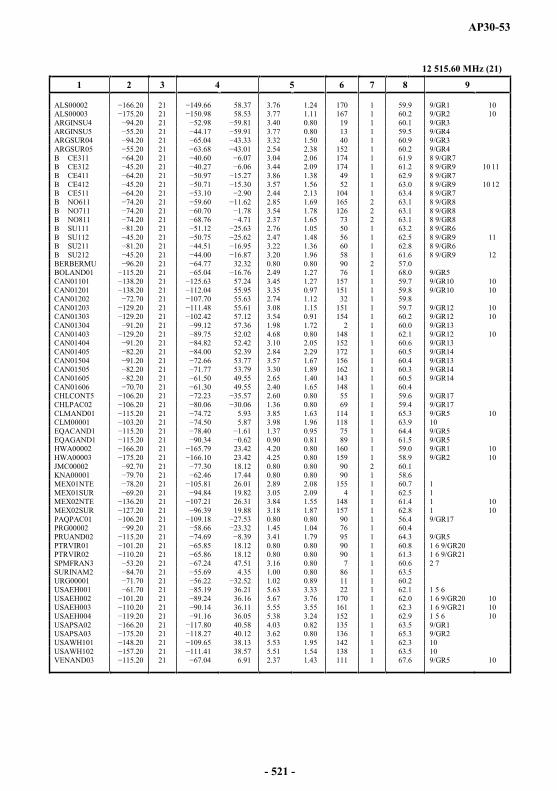
AP30-53
12 515.60 MHz (21)
1 2 3 4 5 6 7 8 9
ALS00002 21 58.37 3.76 1.24 170 1 59.9 9/GR1 10ALS00003 21 58.53 3.77 1.11 167 1 60.2 9/GR2 10ARGINSU4 21 3.40 0.80 19 1 60.1 9/GR3ARGINSU5 21 3.77 0.80 13 1 59.5 9/GR4ARGSUR04 21 3.32 1.50 40 1 60.9 9/GR3ARGSUR05 21 2.54 2.38 152 1 60.2 9/GR4B CE311 21 3.04 2.06 174 1 61.9 8 9/GR7B CE312 21 3.44 2.09 174 1 61.2 8 9/GR9 10 11B CE411 21 3.86 1.38 49 1 62.9 8 9/GR7B CE412 21 3.57 1.56 52 1 63.0 8 9/GR9 10 12B CE511 21 2.44 2.13 104 1 63.4 8 9/GR7B NO611 21 2.85 1.69 165 2 63.1 8 9/GR8B NO711 21 3.54 1.78 126 2 63.1 8 9/GR8B NO811 21 2.37 1.65 73 2 63.1 8 9/GR8B SU111 21 2.76 1.05 50 1 63.2 8 9/GR6B SU112 21 2.47 1.48 56 1 62.5 8 9/GR9 11B SU211 21 3.22 1.36 60 1 62.8 8 9/GR6B SU212 21 3.20 1.96 58 1 61.6 8 9/GR9 12BERBERMU 21 32.32 0.80 0.80 90 2 57.0BOLAND01 21 2.49 1.27 76 1 68.0 9/GR5CAN01101 21 57.24 3.45 1.27 157 1 59.7 9/GR10 10CAN01201 21 55.95 3.35 0.97 151 1 59.8 9/GR10 10CAN01202 21 55.63 2.74 1.12 32 1 59.8CAN01203 21 55.61 3.08 1.15 151 1 59.7 9/GR12 10CAN01303 21 57.12 3.54 0.91 154 1 60.2 9/GR12 10CAN01304 21 57.36 1.98 1.72 2 1 60.0 9/GR13CAN01403 .20 21 52.02 4.68 0.80 148 1 62.1 9/GR12 10CAN01404 21 52.42 3.10 2.05 152 1 60.6 9/GR13CAN01405 21 52.39 2.84 2.29 172 1 60.5 9/GR14CAN01504 21 53.77 3.57 1.67 156 1 60.4 9/GR13CAN01505 21 53.79 3.30 1.89 162 1 60.3 9/GR14CAN01605 21 49.55 2.65 1.40 143 1 60.5 9/GR14CAN01606 21 49.55 2.40 1.65 148 1 60.4CHLCONT5 21 2.60 0.80 55 1 59.6 9/GR17CHLPAC02 21 06 1.36 0.80 69 1 59.4 9/GR17CLMAND01 21 5.93 3.85 1.63 114 1 65.3 9/GR5 10CLM00001 21 5.87 3.98 1.96 118 1 63.9 10EQACAND1 21 1.37 0.95 75 1 64.4 9/GR5EQAGAND1 21 0.90 0.81 89 1 61.5 9/GR5HWA00002 21 23.42 4.20 0.80 160 1 59.0 9/GR1 10HWA00003 21 23.42 4.25 0.80 159 1 58.9 9/GR2 10JMC00002 21 18.12 0.80 0.80 90 2 60.1KNA00001 79.70 21 62.46 17.44 0.80 0.80 90 1 58.6MEX01NTE 21 26.01 2.89 2.08 155 1 60.7 1MEX01SUR 21 19.82 3.05 2.09 4 1 62.5 1MEX02NTE 21 26.31 3.84 1.55 148 1 61.4 1 10MEX02SUR 21 19.88 3.18 1.87 157 1 62.8 1 10PAQPAC01 21 0.80 0.80 90 1 56.4 9/GR17PRG00002 21 1.45 1.04 76 1 60.4PRUAND02 21 3.41 1.79 95 1 64.3 9/GR5PTRVIR01 21 18.12 0.80 0.80 90 1 60.8 1 6 9/GR20PTRVIR02 21 18.12 0.80 0.80 90 1 61.3 1 6 9/GR21SPMFRAN3 21 47.51 3.16 0.80 7 1 60.6 2 7SURINAM2 21 4.35 1.00 0.80 86 1 63.5URG00001 21 1.02 0.89 11 1 60.2USAEH001 21 36.21 5.63 3.33 22 1 62.1 1 5 6USAEH002 21 36.16 5.67 3.76 170 1 62.0 1 6 9/GR20 10USAEH003 21 36.11 5.55 3.55 161 1 62.3 1 6 9/GR21 10USAEH004 21 36.05 5.38 3.24 152 1 62.9 1 5 6 10USAPSA02 21 40.58 4.03 0.82 135 1 63.5 9/GR1USAPSA03 21 40.12 3.62 0.80 136 1 65.3 9/GR2USAWH101 21 38.13 5.53 1.95 142 1 62.3 10USAWH102 21 38.57 5.51 1.54 138 1 63.5 10VENAND03 21 6.91 2.37 1.43 111 1 67.6 9/GR5 10
- 521 -
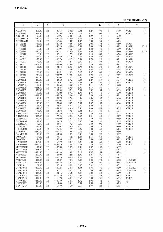
AP30-54
12 530.18 MHz (22)
1 2 3 4 5 6 7 8 9
ALS00002 22 58.52 3.81 1.23 171 2 59.9 9/GR1 10ALS00003 22 58.54 3.77 1.11 167 2 60.2 9/GR2 10ARGNORT4 22 3.86 1.99 48 2 66.0ARGNORT5 80 22 3.24 2.89 47 2 63.8ATNBEAM1 22 14.87 1.83 0.80 39 2 61.3B CE311 22 3.04 2.06 174 2 61.9 8 9/GR7B CE312 22 3.44 2.09 174 2 61.2 8 9/GR9 10 11B CE411 22 5.26 3.86 1.38 49 2 62.9 8 9/GR7B CE412 22 3.57 1.56 52 2 63.0 8 9/GR9 10 12B CE511 22 2.42 2.15 107 2 63.4 8 9/GR7B NO611 22 2.86 1.69 165 1 63.1 8 9/GR8B NO711 22 .78 3.54 1.78 126 1 63.1 8 9/GR8B NO811 22 2.37 1.65 73 1 63.1 8 9/GR8B SE911 22 2.22 0.80 62 2 65.7 8B SU111 22 2.76 1.06 50 2 63.1 8 9/GR6B SU112 22 2.47 1.48 56 2 62.6 8 9/GR9 11B SU211 22 3.22 1.37 60 2 62.8 8 9/GR6B SU212 22 3.27 1.92 59 2 61.6 8 9/GR9 12BLZ00001 22 17.27 0.80 0.80 90 2 59.2CAN01101 22 57.24 3.45 1.27 157 2 59.7 9/GR10 10CAN01201 22 55.89 3.33 0.98 151 2 59.8 9/GR10 10CAN01202 22 55.62 2.75 1.11 32 2 59.8CAN01203 22 55.56 3.07 1.15 151 2 59.7 9/GR12 10CAN01303 22 57.12 3.54 0.92 154 2 60.3 9/GR12 10CAN01304 22 57.33 1.96 1.73 1 2 60.0 9/GR13CAN01403 22 52.02 4.67 0.80 148 2 62.1 9/GR12 10CAN01404 22 52.41 3.09 2.06 153 2 60.6 9/GR13CAN01405 22 52.34 2.82 2.30 172 2 60.5 9/GR14CAN01504 22 53.78 3.57 1.67 157 2 60.4 9/GR13CAN01505 22 53.76 3.30 1.89 162 2 60.3 9/GR14CAN01605 22 49.50 2.66 1.39 144 2 60.5 9/GR14CAN01606 22 49.51 2.41 1.65 148 2 60.4CHLCONT4 22 2.21 0.80 68 2 59.3 9/GR16CHLCONT6 22 3.65 1.31 39 2 59.7 9/GR16CRBBAH01 22 24.13 1.83 0.80 141 1 61.9 9/GR18CRBBER01 22 32.13 0.80 0.80 90 1 56.9 9/GR18CRBBLZ01 22 17.26 0.80 0.80 90 1 58.9 9/GR18CRBEC001 22 8.26 4.20 0.86 115 1 64.6 9/GR18CRBJMC01 22 17.97 0.99 0.80 151 1 61.3 9/GR18CTR00201 22 9.67 0.82 0.80 119 2 66.0DMAIFRB1 22 15.35 0.80 0.80 90 2 58.7EQAC0001 22 1.48 1.15 65 1 63.3 9/GR19EQAG0001 22 0.94 0.89 99 1 61.2 9/GR19HWA00002 22 23.32 4.20 0.80 160 2 59.0 9/GR1 10HWA00003 22 23.42 4.25 0.80 159 2 59.0 9/GR2 10MEX01NTE 22 25.99 2.88 2.07 155 2 60.7 1MEX02NTE 22 26.32 3.80 1.57 149 2 61.4 1 10MEX02SUR 22 19.88 3.19 1.87 158 2 62.8 1 10NCG00003 22 12.90 1.05 1.01 176 1 63.6PRU00004 22 3.74 2.45 112 2 63.1PTRVIR01 22 18.12 0.80 0.80 90 2 60.8 1 6 9/GR20PTRVIR02 22 18.12 0.80 0.80 90 2 61.4 1 6 9/GR21USAEH001 22 36.21 5.63 3.32 22 2 62.1 1 5 6USAEH002 22 36.16 5.65 3.78 170 2 62.0 1 6 9/GR20 10USAEH003 22 36.11 5.55 3.56 161 2 62.3 1 6 9/GR21 10USAEH004 22 36.05 5.38 3.24 153 2 62.9 1 5 6 10USAPSA02 22 40.58 4.04 0.82 135 2 63.5 9/GR1USAPSA03 22 40.15 3.63 0.80 136 2 65.3 9/GR2USAWH101 22 38.13 5.52 1.96 142 2 62.3 10USAWH102 22 38.57 5.51 1.55 138 2 63.5 10VEN11VEN 22 6.90 2.50 1.77 122 2 65.5 10
- 522 -
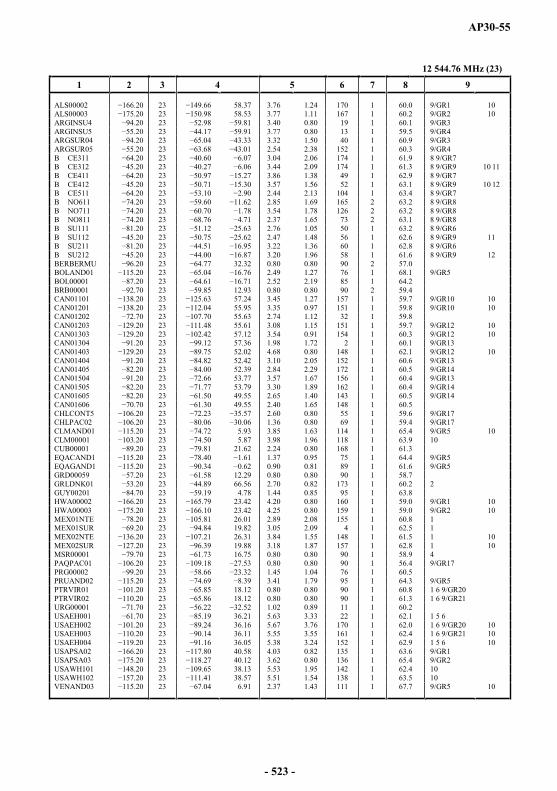
AP30-55
12 544.76 MHz (23)
1 2 3 4 5 6 7 8 9
ALS00002 23 58.37 3.76 1.24 170 1 60.0 9/GR1 10ALS00003 23 58.53 3.77 1.11 167 1 60.2 9/GR2 10ARGINSU4 23 3.40 0.80 19 1 60.1 9/GR3ARGINSU5 23 91 3.77 0.80 13 1 59.5 9/GR4ARGSUR04 23 3.32 1.50 40 1 60.9 9/GR3ARGSUR05 23 2.54 2.38 152 1 60.3 9/GR4B CE311 23 3.04 2.06 174 1 61.9 8 9/GR7B CE312 23 3.44 2.09 174 1 61.3 8 9/GR9 10 11B CE411 23 3.86 1.38 49 1 62.9 8 9/GR7B CE412 23 3.57 1.56 52 1 63.1 8 9/GR9 10 12B CE511 23 2.44 2.13 104 1 63.4 8 9/GR7B NO611 23 2.85 1.69 165 2 63.2 8 9/GR8B NO711 23 3.54 1.78 126 2 63.2 8 9/GR8B NO811 23 2.37 1.65 73 2 63.1 8 9/GR8B SU111 23 2.76 1.05 50 1 63.2 8 9/GR6B SU112 23 2.47 1.48 56 1 62.6 8 9/GR9 11B SU211 23 3.22 1.36 60 1 62.8 8 9/GR6B SU212 23 3.20 1.96 58 1 61.6 8 9/GR9 12BERBERMU 23 32.32 0.80 0.80 90 2 57.0BOLAND01 23 2.49 1.27 76 1 68.1 9/GR5BOL00001 23 2.52 2.19 85 1 64.2BRB00001 23 12.93 0.80 0.80 90 2 59.4CAN01101 23 57.24 3.45 1.27 157 1 59.7 9/GR10 10CAN01201 23 55.95 3.35 0.97 151 1 59.8 9/GR10 10CAN01202 23 55.63 2.74 1.12 32 1 59.8CAN01203 23 55.61 3.08 1.15 151 1 59.7 9/GR12 10CAN01303 23 57.12 3.54 0.91 154 1 60.3 9/GR12 10CAN01304 23 57.36 1.98 1.72 2 1 60.1 9/GR13CAN01403 9.20 23 52.02 4.68 0.80 148 1 62.1 9/GR12 10CAN01404 23 52.42 3.10 2.05 152 1 60.6 9/GR13CAN01405 23 52.39 2.84 2.29 172 1 60.5 9/GR14CAN01504 23 53.77 3.57 1.67 156 1 60.4 9/GR13CAN01505 23 53.79 3.30 1.89 162 1 60.4 9/GR14CAN01605 23 49.55 2.65 1.40 143 1 60.5 9/GR14CAN01606 23 49.55 2.40 1.65 148 1 60.5CHLCONT5 23 2.60 0.80 55 1 59.6 9/GR17CHLPAC02 23 .06 1.36 0.80 69 1 59.4 9/GR17CLMAND01 23 5.93 3.85 1.63 114 1 65.4 9/GR5 10CLM00001 23 5.87 3.98 1.96 118 1 63.9 10CUB00001 23 21.62 2.24 0.80 168 1 61.3EQACAND1 23 1.37 0.95 75 1 64.4 9/GR5EQAGAND1 23 0.90 0.81 89 1 61.6 9/GR5GRD00059 23 12.29 0.80 0.80 90 1 58.7GRLDNK01 23 66.56 2.70 0.82 173 1 60.2 2GUY00201 23 4.78 1.44 0.85 95 1 63.8HWA00002 20 23 23.42 4.20 0.80 160 1 59.0 9/GR1 10HWA00003 23 23.42 4.25 0.80 159 1 59.0 9/GR2 10MEX01NTE 23 26.01 2.89 2.08 155 1 60.8 1MEX01SUR 23 19.82 3.05 2.09 4 1 62.5 1MEX02NTE 23 26.31 3.84 1.55 148 1 61.5 1 10MEX02SUR 23 19.88 3.18 1.87 157 1 62.8 1 10MSR00001 23 16.75 0.80 0.80 90 1 58.9 4PAQPAC01 23 0.80 0.80 90 1 56.4 9/GR17PRG00002 23 1.45 1.04 76 1 60.5PRUAND02 23 3.41 1.79 95 1 64.3 9/GR5PTRVIR01 23 18.12 0.80 0.80 90 1 60.8 1 6 9/GR20PTRVIR02 23 18.12 0.80 0.80 90 1 61.3 1 6 9/GR21URG00001 23 1.02 0.89 11 1 60.2USAEH001 23 36.21 5.63 3.33 22 1 62.1 1 5 6USAEH002 23 36.16 5.67 3.76 170 1 62.0 1 6 9/GR20 10USAEH003 23 36.11 5.55 3.55 161 1 62.4 1 6 9/GR21 10USAEH004 23 36.05 5.38 3.24 152 1 62.9 1 5 6 10USAPSA02 23 40.58 4.03 0.82 135 1 63.6 9/GR1USAPSA03 23 40.12 3.62 0.80 136 1 65.4 9/GR2USAWH101 23 38.13 5.53 1.95 142 1 62.4 10USAWH102 23 38.57 5.51 1.54 138 1 63.5 10VENAND03 23 6.91 2.37 1.43 111 1 67.7 9/GR5 10
- 523 -
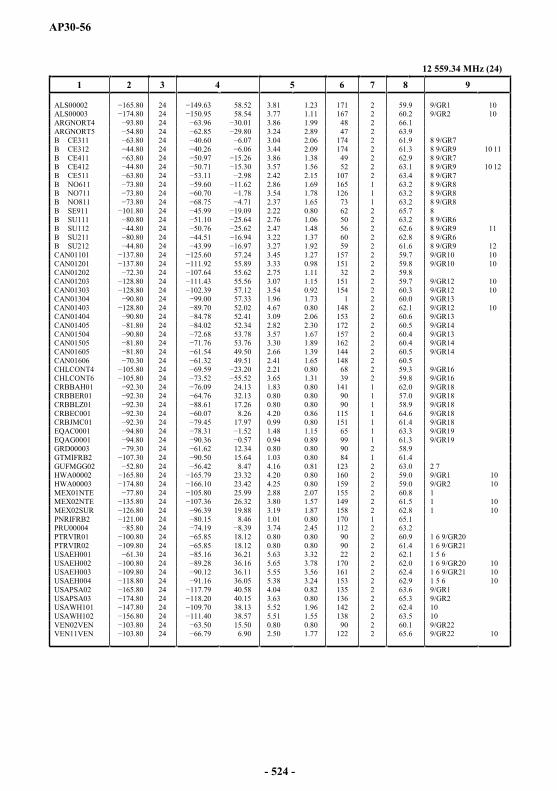
AP30-56
12 559.34 MHz (24)
1 2 3 4 5 6 7 8 9
ALS00002 24 58.52 3.81 1.23 171 2 59.9 9/GR1 10ALS00003 24 58.54 3.77 1.11 167 2 60.2 9/GR2 10ARGNORT4 3.80 24 3.86 1.99 48 2 66.1ARGNORT5 24 3.24 2.89 47 2 63.9B CE311 24 3.04 2.06 174 2 61.9 8 9/GR7B CE312 24 3.44 2.09 174 2 61.3 8 9/GR9 10 11B CE411 24 3.86 1.38 49 2 62.9 8 9/GR7B CE412 24 3.57 1.56 52 2 63.1 8 9/GR9 10 12B CE511 24 2.42 2.15 107 2 63.4 8 9/GR7B NO611 24 2.86 1.69 165 1 63.2 8 9/GR8B NO711 24 3.54 1.78 126 1 63.2 8 9/GR8B NO811 24 2.37 1.65 73 1 63.2 8 9/GR8B SE911 24 2.22 0.80 62 2 65.7 8B SU111 24 2.76 1.06 50 2 63.2 8 9/GR6B SU112 24 2.47 1.48 56 2 62.6 8 9/GR9 11B SU211 24 3.22 1.37 60 2 62.8 8 9/GR6B SU212 24 3.27 1.92 59 2 61.6 8 9/GR9 12CAN01101 24 57.24 3.45 1.27 157 2 59.7 9/GR10 10CAN01201 24 55.89 3.33 0.98 151 2 59.8 9/GR10 10CAN01202 24 55.62 2.75 1.11 32 2 59.8CAN01203 24 55.56 3.07 1.15 151 2 59.7 9/GR12 10CAN01303 24 57.12 3.54 0.92 154 2 60.3 9/GR12 10CAN01304 24 57.33 1.96 1.73 1 2 60.0 9/GR13CAN01403 24 52.02 4.67 0.80 148 2 62.1 9/GR12 10CAN01404 24 52.41 3.09 2.06 153 2 60.6 9/GR13CAN01405 24 52.34 2.82 2.30 172 2 60.5 9/GR14CAN01504 24 53.78 3.57 1.67 157 2 60.4 9/GR13CAN01505 24 53.76 3.30 1.89 162 2 60.4 9/GR14CAN01605 24 49.50 2.66 1.39 144 2 60.5 9/GR14CAN01606 24 49.51 2.41 1.65 148 2 60.5CHLCONT4 24 2.21 0.80 68 2 59.3 9/GR16CHLCONT6 24 3.65 1.31 39 2 59.8 9/GR16CRBBAH01 24 24.13 1.83 0.80 141 1 62.0 9/GR18CRBBER01 24 32.13 0.80 0.80 90 1 57.0 9/GR18CRBBLZ01 24 17.26 0.80 0.80 90 1 58.9 9/GR18CRBEC001 24 8.26 4.20 0.86 115 1 64.6 9/GR18CRBJMC01 24 17.97 0.99 0.80 151 1 61.4 9/GR18EQAC0001 24 1.48 1.15 65 1 63.3 9/GR19EQAG0001 24 0.94 0.89 99 1 61.3 9/GR19GRD00003 24 12.34 0.80 0.80 90 2 58.9GTMIFRB2 24 15.64 1.03 0.80 84 1 61.4GUFMGG02 24 8.47 4.16 0.81 123 2 63.0 2 7HWA00002 24 23.32 4.20 0.80 160 2 59.0 9/GR1 10HWA00003 24 23.42 4.25 0.80 159 2 59.0 9/GR2 10MEX01NTE 24 25.99 2.88 2.07 155 2 60.8 1MEX02NTE 24 26.32 3.80 1.57 149 2 61.5 1 10MEX02SUR 24 19.88 3.19 1.87 158 2 62.8 1 10PNRIFRB2 24 8.46 1.01 0.80 170 1 65.1PRU00004 24 3.74 2.45 112 2 63.2PTRVIR01 24 18.12 0.80 0.80 90 2 60.9 1 6 9/GR20PTRVIR02 24 18.12 0.80 0.80 90 2 61.4 1 6 9/GR21USAEH001 24 36.21 5.63 3.32 22 2 62.1 1 5 6USAEH002 24 36.16 5.65 3.78 170 2 62.0 1 6 9/GR20 10USAEH003 24 36.11 5.55 3.56 161 2 62.4 1 6 9/GR21 10USAEH004 24 36.05 5.38 3.24 153 2 62.9 1 5 6 10USAPSA02 24 40.58 4.04 0.82 135 2 63.6 9/GR1USAPSA03 24 40.15 3.63 0.80 136 2 65.3 9/GR2USAWH101 24 38.13 5.52 1.96 142 2 62.4 10USAWH102 24 38.57 5.51 1.55 138 2 63.5 10VEN02VEN 24 15.50 0.80 0.80 90 2 60.1 9/GR22VEN11VEN 24 6.90 2.50 1.77 122 2 65.6 9/GR22 10
- 524 -

AP30-57
12 573.92 MHz (25)
1 2 3 4 5 6 7 8 9
ALS00002 25 58.37 3.76 1.24 170 1 59.9 9/GR1 10ALS00003 25 58.53 3.77 1.11 167 1 60.2 9/GR2 10ARGINSU4 25 3.40 0.80 19 1 60.1 9/GR3ARGINSU5 25 3.77 0.80 13 1 59.5 9/GR4ARGSUR04 25 3.32 1.50 40 1 60.9 9/GR3ARGSUR05 25 2.54 2.38 152 1 60.2 9/GR4B CE311 25 3.04 2.06 174 1 61.9 8 9/GR7B CE312 25 3.44 2.09 174 1 61.2 8 9/GR9 10 11B CE411 25 3.86 1.38 49 1 62.9 8 9/GR7B CE412 25 3.57 1.56 52 1 63.0 8 9/GR9 10 12B CE511 25 2.44 2.13 104 1 63.4 8 9/GR7B NO611 25 2.85 1.69 165 2 63.1 8 9/GR8B NO711 25 3.54 1.78 126 2 63.1 8 9/GR8B NO811 25 2.37 1.65 73 2 63.1 8 9/GR8B SU111 25 2.76 1.05 50 1 63.2 8 9/GR6B SU112 25 2.47 1.48 56 1 62.5 8 9/GR9 11B SU211 25 3.22 1.36 60 1 62.8 8 9/GR6B SU212 25 3.20 1.96 58 1 61.6 8 9/GR9 12BERBERMU 25 32.32 0.80 0.80 90 2 57.0BOLAND01 25 2.49 1.27 76 1 68.0 9/GR5CAN01101 25 57.24 3.45 1.27 157 1 59.7 9/GR10 10CAN01201 25 55.95 3.35 0.97 151 1 59.8 9/GR10 10CAN01202 25 55.63 2.74 1.12 32 1 59.8CAN01203 25 55.61 3.08 1.15 151 1 59.7 9/GR12 10CAN01303 25 57.12 3.54 0.91 154 1 60.2 9/GR12 10CAN01304 25 57.36 1.98 1.72 2 1 60.0 9/GR13CAN01403 25 52.02 4.68 0.80 148 1 62.1 9/GR12 10CAN01404 25 52.42 3.10 2.05 152 1 60.6 9/GR13CAN01405 25 52.39 2.84 2.29 172 1 60.5 9/GR14CAN01504 25 53.77 3.57 1.67 156 1 60.4 9/GR13CAN01505 25 53.79 3.30 1.89 162 1 60.3 9/GR14CAN01605 25 49.55 2.65 1.40 143 1 60.5 9/GR14CAN01606 25 49.55 2.40 1.65 148 1 60.4CHLCONT5 25 2.60 0.80 55 1 59.6 9/GR17CHLPAC02 25 1.36 0.80 69 1 59.4 9/GR17CLMAND01 25 5.93 3.85 1.63 114 1 65.3 9/GR5 10CLM00001 25 5.87 3.98 1.96 118 1 63.9 10EQACAND1 25 1.37 0.95 75 1 64.4 9/GR5EQAGAND1 25 0.90 0.81 89 1 61.5 9/GR5HWA00002 25 23.42 4.20 0.80 160 1 59.0 9/GR1 10HWA00003 25 23.42 4.25 0.80 159 1 58.9 9/GR2 10JMC00002 25 18.12 0.80 0.80 90 2 60.1KNA00001 79.70 25 62.46 17.44 0.80 0.80 90 1 58.6MEX01NTE 25 26.01 2.89 2.08 155 1 60.7 1MEX01SUR 25 19.82 3.05 2.09 4 1 62.5 1MEX02NTE 25 26.31 3.84 1.55 148 1 61.4 1 10MEX02SUR 25 19.88 3.18 1.87 157 1 62.8 1 10PAQPAC01 25 0.80 0.80 90 1 56.4 9/GR17PRG00002 25 1.45 1.04 76 1 60.4PRUAND02 25 3.41 1.79 95 1 64.3 9/GR5PTRVIR01 25 18.12 0.80 0.80 90 1 60.8 1 6 9/GR20PTRVIR02 25 18.12 0.80 0.80 90 1 61.3 1 6 9/GR21SPMFRAN3 25 47.51 3.16 0.80 7 1 60.6 2 7SURINAM2 25 4.35 1.00 0.80 86 1 63.5URG00001 25 1.02 0.89 11 1 60.2USAEH001 25 36.21 5.63 3.33 22 1 62.1 1 5 6USAEH002 25 36.16 5.67 3.76 170 1 62.0 1 6 9/GR20 10USAEH003 25 36.11 5.55 3.55 161 1 62.3 1 6 9/GR21 10USAEH004 25 36.05 5.38 3.24 152 1 62.9 1 5 6 10USAPSA02 25 40.58 4.03 0.82 135 1 63.5 9/GR1USAPSA03 25 40.12 3.62 0.80 136 1 65.3 9/GR2USAWH101 25 38.13 5.53 1.95 142 1 62.3 10USAWH102 25 38.57 5.51 1.54 138 1 63.5 10VENAND03 25 6.91 2.37 1.43 111 1 67.6 9/GR5 10
- 525 -
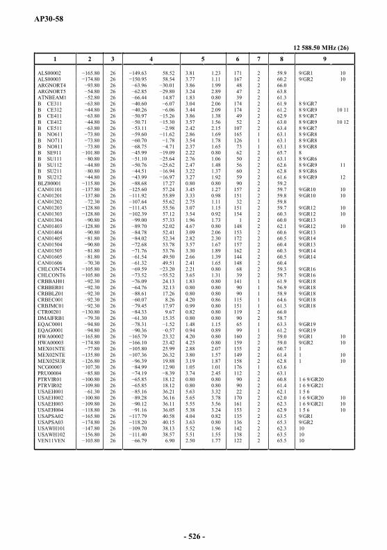
AP30-58
12 588.50 MHz (26)
1 2 3 4 5 6 7 8 9
ALS00002 26 58.52 3.81 1.23 171 2 59.9 9/GR1 10ALS00003 26 58.54 3.77 1.11 167 2 60.2 9/GR2 10ARGNORT4 26 3.86 1.99 48 2 66.0ARGNORT5 26 3.24 2.89 47 2 63.8ATNBEAM1 26 14.87 1.83 0.80 39 2 61.3B CE311 26 3.04 2.06 174 2 61.9 8 9/GR7B CE312 26 3.44 2.09 174 2 61.2 8 9/GR9 10 11B CE411 26 3.86 1.38 49 2 62.9 8 9/GR7B CE412 26 3.57 1.56 52 2 63.0 8 9/GR9 10 12B CE511 26 2.42 2.15 107 2 63.4 8 9/GR7B NO611 26 2.86 1.69 165 1 63.1 8 9/GR8B NO711 26 3.54 1.78 126 1 63.1 8 9/GR8B NO811 26 2.37 1.65 73 1 63.1 8 9/GR8B SE911 26 2.22 0.80 62 2 65.7 8B SU111 26 2.76 1.06 50 2 63.1 8 9/GR6B SU112 26 2.47 1.48 56 2 62.6 8 9/GR9 11B SU211 0 26 3.22 1.37 60 2 62.8 8 9/GR6B SU212 26 3.27 1.92 59 2 61.6 8 9/GR9 12BLZ00001 26 17.27 0.80 0.80 90 2 59.2CAN01101 26 57.24 3.45 1.27 157 2 59.7 9/GR10 10CAN01201 26 111.92 55.89 3.33 0.98 151 2 59.8 9/GR10 10CAN01202 26 55.62 2.75 1.11 32 2 59.8CAN01203 26 55.56 3.07 1.15 151 2 59.7 9/GR12 10CAN01303 26 57.12 3.54 0.92 154 2 60.3 9/GR12 10CAN01304 26 00 57.33 1.96 1.73 1 2 60.0 9/GR13CAN01403 26 52.02 4.67 0.80 148 2 62.1 9/GR12 10CAN01404 26 52.41 3.09 2.06 153 2 60.6 9/GR13CAN01405 26 52.34 2.82 2.30 172 2 60.5 9/GR14CAN01504 26 53.78 3.57 1.67 157 2 60.4 9/GR13CAN01505 26 53.76 3.30 1.89 162 2 60.3 9/GR14CAN01605 26 49.50 2.66 1.39 144 2 60.5 9/GR14CAN01606 26 49.51 2.41 1.65 148 2 60.4CHLCONT4 26 2.21 0.80 68 2 59.3 9/GR16CHLCONT6 26 3.65 1.31 39 2 59.7 9/GR16CRBBAH01 26 24.13 1.83 0.80 141 1 61.9 9/GR18CRBBER01 26 32.13 0.80 0.80 90 1 56.9 9/GR18CRBBLZ01 26 17.26 0.80 0.80 90 1 58.9 9/GR18CRBEC001 26 8.26 4.20 0.86 115 1 64.6 9/GR18CRBJMC01 26 17.97 0.99 0.80 151 1 61.3 9/GR18CTR00201 26 9.67 0.82 0.80 119 2 66.0DMAIFRB1 26 15.35 0.80 0.80 90 2 58.7EQAC0001 .80 26 1.48 1.15 65 1 63.3 9/GR19EQAG0001 26 0.94 0.89 99 1 61.2 9/GR19HWA00002 26 23.32 4.20 0.80 160 2 59.0 9/GR1 10HWA00003 26 23.42 4.25 0.80 159 2 59.0 9/GR2 10MEX01NTE 26 25.99 2.88 2.07 155 2 60.7 1MEX02NTE 26 26.32 3.80 1.57 149 2 61.4 1 10MEX02SUR 26 19.88 3.19 1.87 158 2 62.8 1 10NCG00003 26 12.90 1.05 1.01 176 1 63.6PRU00004 26 3.74 2.45 112 2 63.1PTRVIR01 26 18.12 0.80 0.80 90 2 60.8 1 6 9/GR20PTRVIR02 26 18.12 0.80 0.80 90 2 61.4 1 6 9/GR21USAEH001 26 36.21 5.63 3.32 22 2 62.1 1 5 6USAEH002 26 36.16 5.65 3.78 170 2 62.0 1 6 9/GR20 10USAEH003 26 36.11 5.55 3.56 161 2 62.3 1 6 9/GR21 10USAEH004 26 36.05 5.38 3.24 153 2 62.9 1 5 6 10USAPSA02 26 40.58 4.04 0.82 135 2 63.5 9/GR1USAPSA03 26 40.15 3.63 0.80 136 2 65.3 9/GR2USAWH101 26 38.13 5.52 1.96 142 2 62.3 10USAWH102 26 38.57 5.51 1.55 138 2 63.5 10VEN11VEN 26 6.90 2.50 1.77 122 2 65.5 10
- 526 -
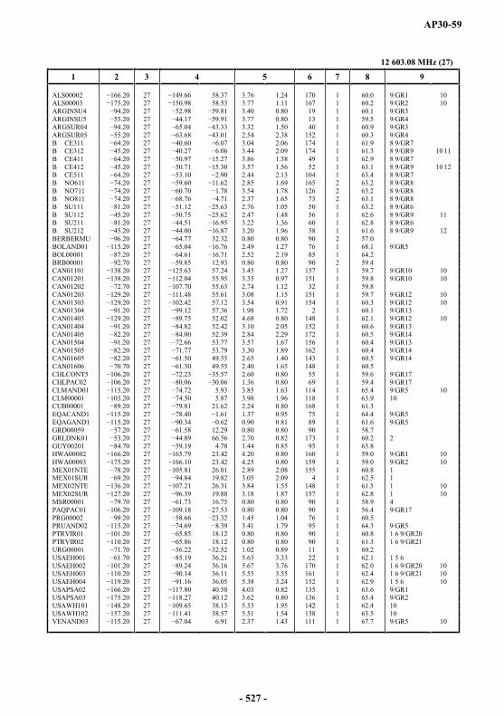
AP30-59
12 603.08 MHz (27)
1 2 3 4 5 6 7 8 9
ALS00002 27 58.37 3.76 1.24 170 1 60.0 9/GR1 10ALS00003 27 58.53 3.77 1.11 167 1 60.2 9/GR2 10ARGINSU4 27 3.40 0.80 19 1 60.1 9/GR3ARGINSU5 27 3.77 0.80 13 1 59.5 9/GR4ARGSUR04 27 3.32 1.50 40 1 60.9 9/GR3ARGSUR05 27 2.54 2.38 152 1 60.3 9/GR4B CE311 27 3.04 2.06 174 1 61.9 8 9/GR7B CE312 27 3.44 2.09 174 1 61.3 8 9/GR9 10 11B CE411 27 3.86 1.38 49 1 62.9 8 9/GR7B CE412 27 3.57 1.56 52 1 63.1 8 9/GR9 10 12B CE511 27 2.44 2.13 104 1 63.4 8 9/GR7B NO611 27 2.85 1.69 165 2 63.2 8 9/GR8B NO711 27 3.54 1.78 126 2 63.2 8 9/GR8B NO811 27 2.37 1.65 73 2 63.1 8 9/GR8B SU111 27 2.76 1.05 50 1 63.2 8 9/GR6B SU112 27 2.47 1.48 56 1 62.6 8 9/GR9 11B SU211 27 3.22 1.36 60 1 62.8 8 9/GR6B SU212 27 3.20 1.96 58 1 61.6 8 9/GR9 12BERBERMU 27 32.32 0.80 0.80 90 2 57.0BOLAND01 27 2.49 1.27 76 1 68.1 9/GR5BOL00001 27 16.71 2.52 2.19 85 1 64.2BRB00001 27 12.93 0.80 0.80 90 2 59.4CAN01101 27 57.24 3.45 1.27 157 1 59.7 9/GR10 10CAN01201 27 55.95 3.35 0.97 151 1 59.8 9/GR10 10CAN01202 27 55.63 2.74 1.12 32 1 59.8CAN01203 27 55.61 3.08 1.15 151 1 59.7 9/GR12 10CAN01303 27 57.12 3.54 0.91 154 1 60.3 9/GR12 10CAN01304 27 57.36 1.98 1.72 2 1 60.1 9/GR13CAN01403 27 52.02 4.68 0.80 148 1 62.1 9/GR12 10CAN01404 27 52.42 3.10 2.05 152 1 60.6 9/GR13CAN01405 27 52.39 2.84 2.29 172 1 60.5 9/GR14CAN01504 27 53.77 3.57 1.67 156 1 60.4 9/GR13CAN01505 27 53.79 3.30 1.89 162 1 60.4 9/GR14CAN01605 27 49.55 2.65 1.40 143 1 60.5 9/GR14CAN01606 27 49.55 2.40 1.65 148 1 60.5CHLCONT5 27 2.60 0.80 55 1 59.6 9/GR17CHLPAC02 27 1.36 0.80 69 1 59.4 9/GR17CLMAND01 27 5.93 3.85 1.63 114 1 65.4 9/GR5 10CLM00001 27 5.87 3.98 1.96 118 1 63.9 10CUB00001 27 21.62 2.24 0.80 168 1 61.3EQACAND1 27 1.37 0.95 75 1 64.4 9/GR5EQAGAND1 27 90.34 0.90 0.81 89 1 61.6 9/GR5GRD00059 27 12.29 0.80 0.80 90 1 58.7GRLDNK01 27 66.56 2.70 0.82 173 1 60.2 2GUY00201 27 4.78 1.44 0.85 95 1 63.8HWA00002 27 23.42 4.20 0.80 160 1 59.0 9/GR1 10HWA00003 27 23.42 4.25 0.80 159 1 59.0 9/GR2 10MEX01NTE 27 26.01 2.89 2.08 155 1 60.8 1MEX01SUR 27 19.82 3.05 2.09 4 1 62.5 1MEX02NTE 27 26.31 3.84 1.55 148 1 61.5 1 10MEX02SUR 27 19.88 3.18 1.87 157 1 62.8 1 10MSR00001 27 16.75 0.80 0.80 90 1 58.9 4PAQPAC01 27 0.80 0.80 90 1 56.4 9/GR17PRG00002 27 1.45 1.04 76 1 60.5PRUAND02 27 4.69 3.41 1.79 95 1 64.3 9/GR5PTRVIR01 27 18.12 0.80 0.80 90 1 60.8 1 6 9/GR20PTRVIR02 27 18.12 0.80 0.80 90 1 61.3 1 6 9/GR21URG00001 27 1.02 0.89 11 1 60.2USAEH001 27 36.21 5.63 3.33 22 1 62.1 1 5 6USAEH002 27 36.16 5.67 3.76 170 1 62.0 1 6 9/GR20 10USAEH003 27 36.11 5.55 3.55 161 1 62.4 1 6 9/GR21 10USAEH004 27 36.05 5.38 3.24 152 1 62.9 1 5 6 10USAPSA02 27 7.80 40.58 4.03 0.82 135 1 63.6 9/GR1USAPSA03 27 40.12 3.62 0.80 136 1 65.4 9/GR2USAWH101 27 38.13 5.53 1.95 142 1 62.4 10USAWH102 27 38.57 5.51 1.54 138 1 63.5 10VENAND03 27 6.91 2.37 1.43 111 1 67.7 9/GR5 10
- 527 -
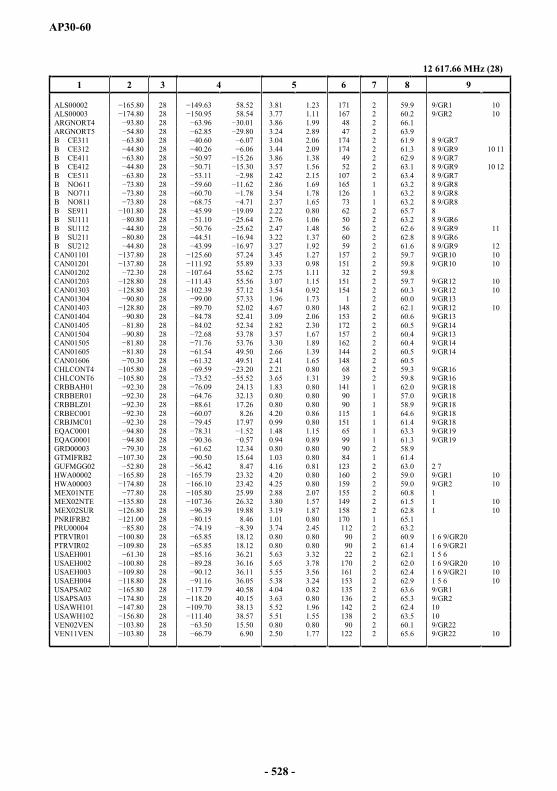
AP30-60
12 617.66 MHz (28)
1 2 3 4 5 6 7 8 9
ALS00002 28 58.52 3.81 1.23 171 2 59.9 9/GR1 10ALS00003 28 58.54 3.77 1.11 167 2 60.2 9/GR2 10ARGNORT4 28 3.86 1.99 48 2 66.1ARGNORT5 28 3.24 2.89 47 2 63.9B CE311 28 3.04 2.06 174 2 61.9 8 9/GR7B CE312 28 3.44 2.09 174 2 61.3 8 9/GR9 10 11B CE411 28 3.86 1.38 49 2 62.9 8 9/GR7B CE412 28 3.57 1.56 52 2 63.1 8 9/GR9 10 12B CE511 28 2.42 2.15 107 2 63.4 8 9/GR7B NO611 28 2.86 1.69 165 1 63.2 8 9/GR8B NO711 28 3.54 1.78 126 1 63.2 8 9/GR8B NO811 28 2.37 1.65 73 1 63.2 8 9/GR8B SE911 28 2.22 0.80 62 2 65.7 8B SU111 28 2.76 1.06 50 2 63.2 8 9/GR6B SU112 28 2.47 1.48 56 2 62.6 8 9/GR9 11B SU211 0.80 28 3.22 1.37 60 2 62.8 8 9/GR6B SU212 28 3.27 1.92 59 2 61.6 8 9/GR9 12CAN01101 28 57.24 3.45 1.27 157 2 59.7 9/GR10 10CAN01201 28 55.89 3.33 0.98 151 2 59.8 9/GR10 10CAN01202 28 55.62 2.75 1.11 32 2 59.8CAN01203 28 55.56 3.07 1.15 151 2 59.7 9/GR12 10CAN01303 28 57.12 3.54 0.92 154 2 60.3 9/GR12 10CAN01304 28 57.33 1.96 1.73 1 2 60.0 9/GR13CAN01403 28 52.02 4.67 0.80 148 2 62.1 9/GR12 10CAN01404 28 52.41 3.09 2.06 153 2 60.6 9/GR13CAN01405 28 52.34 2.82 2.30 172 2 60.5 9/GR14CAN01504 28 53.78 3.57 1.67 157 2 60.4 9/GR13CAN01505 28 1.76 53.76 3.30 1.89 162 2 60.4 9/GR14CAN01605 28 49.50 2.66 1.39 144 2 60.5 9/GR14CAN01606 28 49.51 2.41 1.65 148 2 60.5CHLCONT4 28 2.21 0.80 68 2 59.3 9/GR16CHLCONT6 28 3.65 1.31 39 2 59.8 9/GR16CRBBAH01 28 24.13 1.83 0.80 141 1 62.0 9/GR18CRBBER01 28 32.13 0.80 0.80 90 1 57.0 9/GR18CRBBLZ01 28 17.26 0.80 0.80 90 1 58.9 9/GR18CRBEC001 28 8.26 4.20 0.86 115 1 64.6 9/GR18CRBJMC01 28 17.97 0.99 0.80 151 1 61.4 9/GR18EQAC0001 28 1.48 1.15 65 1 63.3 9/GR19EQAG0001 28 0.94 0.89 99 1 61.3 9/GR19GRD00003 28 12.34 0.80 0.80 90 2 58.9GTMIFRB2 28 15.64 1.03 0.80 84 1 61.4GUFMGG02 28 8.47 4.16 0.81 123 2 63.0 2 7HWA00002 28 23.32 4.20 0.80 160 2 59.0 9/GR1 10HWA00003 28 23.42 4.25 0.80 159 2 59.0 9/GR2 10MEX01NTE 7.80 28 25.99 2.88 2.07 155 2 60.8 1MEX02NTE 28 26.32 3.80 1.57 149 2 61.5 1 10MEX02SUR 28 19.88 3.19 1.87 158 2 62.8 1 10PNRIFRB2 28 8.46 1.01 0.80 170 1 65.1PRU00004 28 3.74 2.45 112 2 63.2PTRVIR01 28 18.12 0.80 0.80 90 2 60.9 1 6 9/GR20PTRVIR02 28 18.12 0.80 0.80 90 2 61.4 1 6 9/GR21USAEH001 28 36.21 5.63 3.32 22 2 62.1 1 5 6USAEH002 28 36.16 5.65 3.78 170 2 62.0 1 6 9/GR20 10USAEH003 28 36.11 5.55 3.56 161 2 62.4 1 6 9/GR21 10USAEH004 28 36.05 5.38 3.24 153 2 62.9 1 5 6 10USAPSA02 28 40.58 4.04 0.82 135 2 63.6 9/GR1USAPSA03 28 40.15 3.63 0.80 136 2 65.3 9/GR2USAWH101 28 38.13 5.52 1.96 142 2 62.4 10USAWH102 28 38.57 5.51 1.55 138 2 63.5 10VEN02VEN 28 15.50 0.80 0.80 90 2 60.1 9/GR22VEN11VEN 28 6.90 2.50 1.77 122 2 65.6 9/GR22 10
- 528 -

AP30-61
12 632.24 MHz (29)
1 2 3 4 5 6 7 8 9
ALS00002 29 58.37 3.76 1.24 170 1 59.9 9/GR1 10ALS00003 29 58.53 3.77 1.11 167 1 60.2 9/GR2 10ARGINSU4 29 3.40 0.80 19 1 60.1 9/GR3ARGINSU5 29 3.77 0.80 13 1 59.5 9/GR4ARGSUR04 29 3.32 1.50 40 1 60.9 9/GR3ARGSUR05 29 2.54 2.38 152 1 60.2 9/GR4B CE311 29 3.04 2.06 174 1 61.9 8 9/GR7B CE312 29 3.44 2.09 174 1 61.2 8 9/GR9 10 11B CE411 29 3.86 1.38 49 1 62.9 8 9/GR7B CE412 29 3.57 1.56 52 1 63.0 8 9/GR9 10 12B CE511 29 2.44 2.13 104 1 63.4 8 9/GR7B NO611 29 2.85 1.69 165 2 63.1 8 9/GR8B NO711 29 3.54 1.78 126 2 63.1 8 9/GR8B NO811 29 2.37 1.65 73 2 63.1 8 9/GR8B SU111 29 2.76 1.05 50 1 63.2 8 9/GR6B SU112 29 2.47 1.48 56 1 62.5 8 9/GR9 11B SU211 29 3.22 1.36 60 1 62.8 8 9/GR6B SU212 29 3.20 1.96 58 1 61.6 8 9/GR9 12BERBERMU 29 32.32 0.80 0.80 90 2 57.0BOLAND01 29 2.49 1.27 76 1 68.0 9/GR5CAN01101 29 57.24 3.45 1.27 157 1 59.7 9/GR10 10CAN01201 29 55.95 3.35 0.97 151 1 59.8 9/GR10 10CAN01202 29 55.63 2.74 1.12 32 1 59.8CAN01203 29 1.48 55.61 3.08 1.15 151 1 59.7 9/GR12 10CAN01303 29 57.12 3.54 0.91 154 1 60.2 9/GR12 10CAN01304 29 57.36 1.98 1.72 2 1 60.0 9/GR13CAN01403 29 52.02 4.68 0.80 148 1 62.1 9/GR12 10CAN01404 29 .82 52.42 3.10 2.05 152 1 60.6 9/GR13CAN01405 29 52.39 2.84 2.29 172 1 60.5 9/GR14CAN01504 29 53.77 3.57 1.67 156 1 60.4 9/GR13CAN01505 29 53.79 3.30 1.89 162 1 60.3 9/GR14CAN01605 29 49.55 2.65 1.40 143 1 60.5 9/GR14CAN01606 29 49.55 2.40 1.65 148 1 60.4CHLCONT5 29 2.60 0.80 55 1 59.6 9/GR17CHLPAC02 29 1.36 0.80 69 1 59.4 9/GR17CLMAND01 29 5.93 3.85 1.63 114 1 65.3 9/GR5 10CLM00001 29 5.87 3.98 1.96 118 1 63.9 10EQACAND1 29 1.37 0.95 75 1 64.4 9/GR5EQAGAND1 29 0.90 0.81 89 1 61.5 9/GR5HWA00002 29 23.42 4.20 0.80 160 1 59.0 9/GR1 10HWA00003 29 23.42 4.25 0.80 159 1 58.9 9/GR2 10JMC00002 29 18.12 0.80 0.80 90 2 60.1KNA00001 79.70 29 62.46 17.44 0.80 0.80 90 1 58.6MEX01NTE 29 26.01 2.89 2.08 155 1 60.7 1MEX01SUR 20 29 19.82 3.05 2.09 4 1 62.5 1MEX02NTE 29 26.31 3.84 1.55 148 1 61.4 1 10MEX02SUR 29 19.88 3.18 1.87 157 1 62.8 1 10PAQPAC01 29 0.80 0.80 90 1 56.4 9/GR17PRG00002 29 .32 1.45 1.04 76 1 60.4PRUAND02 29 3.41 1.79 95 1 64.3 9/GR5PTRVIR01 29 18.12 0.80 0.80 90 1 60.8 1 6 9/GR20PTRVIR02 29 18.12 0.80 0.80 90 1 61.3 1 6 9/GR21SPMFRAN3 29 47.51 3.16 0.80 7 1 60.6 2 7SURINAM2 29 4.35 1.00 0.80 86 1 63.5URG00001 29 1.02 0.89 11 1 60.2USAEH001 29 36.21 5.63 3.33 22 1 62.1 1 5 6USAEH002 29 36.16 5.67 3.76 170 1 62.0 1 6 9/GR20 10USAEH003 29 36.11 5.55 3.55 161 1 62.3 1 6 9/GR21 10USAEH004 29 36.05 5.38 3.24 152 1 62.9 1 5 6 10USAPSA02 29 40.58 4.03 0.82 135 1 63.5 9/GR1USAPSA03 29 40.12 3.62 0.80 136 1 65.3 9/GR2USAWH101 29 38.13 5.53 1.95 142 1 62.3 10USAWH102 29 38.57 5.51 1.54 138 1 63.5 10VENAND03 29 6.91 2.37 1.43 111 1 67.6 9/GR5 10
- 529 -
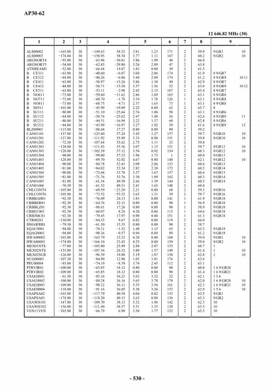
AP30-62
12 646.82 MHz (30)
1 2 3 4 5 6 7 8 9
ALS00002 30 58.52 3.81 1.23 171 2 59.9 9/GR1 10ALS00003 30 58.54 3.77 1.11 167 2 60.2 9/GR2 10ARGNORT4 30 3.86 1.99 48 2 66.0ARGNORT5 30 3.24 2.89 47 2 63.8ATNBEAM1 30 14.87 1.83 0.80 39 2 61.3B CE311 30 3.04 2.06 174 2 61.9 8 9/GR7B CE312 30 3.44 2.09 174 2 61.2 8 9/GR9 10 11B CE411 30 3.86 1.38 49 2 62.9 8 9/GR7B CE412 30 3.57 1.56 52 2 63.0 8 9/GR9 10 12B CE511 30 2.42 2.15 107 2 63.4 8 9/GR7B NO611 30 2.86 1.69 165 1 63.1 8 9/GR8B NO711 30 3.54 1.78 126 1 63.1 8 9/GR8B NO811 30 2.37 1.65 73 1 63.1 8 9/GR8B SE911 30 2.22 0.80 62 2 65.7 8B SU111 30 2.76 1.06 50 2 63.1 8 9/GR6B SU112 30 2.47 1.48 56 2 62.6 8 9/GR9 11B SU211 30 3.22 1.37 60 2 62.8 8 9/GR6B SU212 30 3.27 1.92 59 2 61.6 8 9/GR9 12BLZ00001 30 17.27 0.80 0.80 90 2 59.2CAN01101 30 57.24 3.45 1.27 157 2 59.7 9/GR10 10CAN01201 30 55.89 3.33 0.98 151 2 59.8 9/GR10 10CAN01202 30 55.62 2.75 1.11 32 2 59.8CAN01203 30 55.56 3.07 1.15 151 2 59.7 9/GR12 10CAN01303 30 57.12 3.54 0.92 154 2 60.3 9/GR12 10CAN01304 30 57.33 1.96 1.73 1 2 60.0 9/GR13CAN01403 30 52.02 4.67 0.80 148 2 62.1 9/GR12 10CAN01404 30 52.41 3.09 2.06 153 2 60.6 9/GR13CAN01405 30 52.34 2.82 2.30 172 2 60.5 9/GR14CAN01504 30 53.78 3.57 1.67 157 2 60.4 9/GR13CAN01505 30 53.76 3.30 1.89 162 2 60.3 9/GR14CAN01605 30 49.50 2.66 1.39 144 2 60.5 9/GR14CAN01606 30 49.51 2.41 1.65 148 2 60.4CHLCONT4 30 2.21 0.80 68 2 59.3 9/GR16CHLCONT6 30 3.65 1.31 39 2 59.7 9/GR16CRBBAH01 30 24.13 1.83 0.80 141 1 61.9 9/GR18CRBBER01 30 32.13 0.80 0.80 90 1 56.9 9/GR18CRBBLZ01 30 17.26 0.80 0.80 90 1 58.9 9/GR18CRBEC001 30 8.26 4.20 0.86 115 1 64.6 9/GR18CRBJMC01 30 17.97 0.99 0.80 151 1 61.3 9/GR18CTR00201 30 9.67 0.82 0.80 119 2 66.0DMAIFRB1 30 15.35 0.80 0.80 90 2 58.7EQAC0001 30 1.48 1.15 65 1 63.3 9/GR19EQAG0001 30 0.94 0.89 99 1 61.2 9/GR19HWA00002 30 23.32 4.20 0.80 160 2 59.0 9/GR1 10HWA00003 30 23.42 4.25 0.80 159 2 59.0 9/GR2 10MEX01NTE 30 25.99 2.88 2.07 155 2 60.7 1MEX02NTE 30 26.32 3.80 1.57 149 2 61.4 1 10MEX02SUR 30 19.88 3.19 1.87 158 2 62.8 1 10NCG00003 30 12.90 1.05 1.01 176 1 63.6PRU00004 30 3.74 2.45 112 2 63.1PTRVIR01 30 18.12 0.80 0.80 90 2 60.8 1 6 9/GR20PTRVIR02 30 18.12 0.80 0.80 90 2 61.4 1 6 9/GR21USAEH001 30 36.21 5.63 3.32 22 2 62.1 1 5 6USAEH002 30 36.16 5.65 3.78 170 2 62.0 1 6 9/GR20 10USAEH003 .80 30 36.11 5.55 3.56 161 2 62.3 1 6 9/GR21 10USAEH004 30 36.05 5.38 3.24 153 2 62.9 1 5 6 10USAPSA02 30 40.58 4.04 0.82 135 2 63.5 9/GR1USAPSA03 30 40.15 3.63 0.80 136 2 65.3 9/GR2USAWH101 147.80 30 38.13 5.52 1.96 142 2 62.3 10USAWH102 30 38.57 5.51 1.55 138 2 63.5 10VEN11VEN 30 6.90 2.50 1.77 122 2 65.5 10
- 530 -

AP30-63
12 661.40 MHz (31)
1 2 3 4 5 6 7 8 9
ALS00002 31 58.37 3.76 1.24 170 1 60.0 9/GR1 10ALS00003 31 58.53 3.77 1.11 167 1 60.2 9/GR2 10ARGINSU4 31 3.40 0.80 19 1 60.1 9/GR3ARGINSU5 31 3.77 0.80 13 1 59.5 9/GR4ARGSUR04 31 3.32 1.50 40 1 60.9 9/GR3ARGSUR05 31 2.54 2.38 152 1 60.3 9/GR4B CE311 31 3.04 2.06 174 1 61.9 8 9/GR7B CE312 31 3.44 2.09 174 1 61.3 8 9/GR9 10 11B CE411 31 3.86 1.38 49 1 62.9 8 9/GR7B CE412 31 3.57 1.56 52 1 63.1 8 9/GR9 10 12B CE511 31 2.44 2.13 104 1 63.4 8 9/GR7B NO611 31 2.85 1.69 165 2 63.2 8 9/GR8B NO711 31 3.54 1.78 126 2 63.2 8 9/GR8B NO811 31 2.37 1.65 73 2 63.1 8 9/GR8B SU111 31 2.76 1.05 50 1 63.2 8 9/GR6B SU112 31 2.47 1.48 56 1 62.6 8 9/GR9 11B SU211 31 3.22 1.36 60 1 62.8 8 9/GR6B SU212 31 3.20 1.96 58 1 61.6 8 9/GR9 12BERBERMU 31 32.32 0.80 0.80 90 2 57.0BOLAND01 31 2.49 1.27 76 1 68.1 9/GR5BOL00001 31 2.52 2.19 85 1 64.2BRB00001 31 12.93 0.80 0.80 90 2 59.4CAN01101 31 57.24 3.45 1.27 157 1 59.7 9/GR10 10CAN01201 31 55.95 3.35 0.97 151 1 59.8 9/GR10 10CAN01202 31 55.63 2.74 1.12 32 1 59.8CAN01203 31 11.48 55.61 3.08 1.15 151 1 59.7 9/GR12 10CAN01303 31 57.12 3.54 0.91 154 1 60.3 9/GR12 10CAN01304 31 57.36 1.98 1.72 2 1 60.1 9/GR13CAN01403 31 52.02 4.68 0.80 148 1 62.1 9/GR12 10CAN01404 31 4.82 52.42 3.10 2.05 152 1 60.6 9/GR13CAN01405 31 52.39 2.84 2.29 172 1 60.5 9/GR14CAN01504 31 53.77 3.57 1.67 156 1 60.4 9/GR13CAN01505 31 53.79 3.30 1.89 162 1 60.4 9/GR14CAN01605 31 49.55 2.65 1.40 143 1 60.5 9/GR14CAN01606 31 49.55 2.40 1.65 148 1 60.5CHLCONT5 31 2.60 0.80 55 1 59.6 9/GR17CHLPAC02 31 1.36 0.80 69 1 59.4 9/GR17CLMAND01 31 5.93 3.85 1.63 114 1 65.4 9/GR5 10CLM00001 31 5.87 3.98 1.96 118 1 63.9 10CUB00001 31 21.62 2.24 0.80 168 1 61.3EQACAND1 31 1.37 0.95 75 1 64.4 9/GR5EQAGAND1 31 0.90 0.81 89 1 61.6 9/GR5GRD00059 31 12.29 0.80 0.80 90 1 58.7GRLDNK01 31 66.56 2.70 0.82 173 1 60.2 2GUY00201 31 4.78 1.44 0.85 95 1 63.8HWA00002 31 23.42 4.20 0.80 160 1 59.0 9/GR1 10HWA00003 31 6.10 23.42 4.25 0.80 159 1 59.0 9/GR2 10MEX01NTE 31 26.01 2.89 2.08 155 1 60.8 1MEX01SUR 31 19.82 3.05 2.09 4 1 62.5 1MEX02NTE 31 26.31 3.84 1.55 148 1 61.5 1 10MEX02SUR 31 19.88 3.18 1.87 157 1 62.8 1 10MSR00001 31 16.75 0.80 0.80 90 1 58.9 4PAQPAC01 31 0.80 0.80 90 1 56.4 9/GR17PRG00002 31 1.45 1.04 76 1 60.5PRUAND02 31 3.41 1.79 95 1 64.3 9/GR5PTRVIR01 31 18.12 0.80 0.80 90 1 60.8 1 6 9/GR20PTRVIR02 31 18.12 0.80 0.80 90 1 61.3 1 6 9/GR21URG00001 31 1.02 0.89 11 1 60.2USAEH001 31 36.21 5.63 3.33 22 1 62.1 1 5 6USAEH002 31 36.16 5.67 3.76 170 1 62.0 1 6 9/GR20 10USAEH003 31 36.11 5.55 3.55 161 1 62.4 1 6 9/GR21 10USAEH004 31 36.05 5.38 3.24 152 1 62.9 1 5 6 10USAPSA02 31 40.58 4.03 0.82 135 1 63.6 9/GR1USAPSA03 31 40.12 3.62 0.80 136 1 65.4 9/GR2USAWH101 31 38.13 5.53 1.95 142 1 62.4 10USAWH102 31 38.57 5.51 1.54 138 1 63.5 10VENAND03 31 6.91 2.37 1.43 111 1 67.7 9/GR5 10
- 531 -

AP30-64
12 675.98 MHz (32)
1 2 3 4 5 6 7 8 9
ALS00002 32 58.52 3.81 1.23 171 2 59.9 9/GR1 10ALS00003 32 58.54 3.77 1.11 167 2 60.2 9/GR2 10ARGNORT4 32 3.86 1.99 48 2 66.1ARGNORT5 32 .80 3.24 2.89 47 2 63.9B CE311 32 3.04 2.06 174 2 61.9 8 9/GR7B CE312 32 3.44 2.09 174 2 61.3 8 9/GR9 10 11B CE411 32 3.86 1.38 49 2 62.9 8 9/GR7B CE412 32 3.57 1.56 52 2 63.1 8 9/GR9 10 12B CE511 32 2.42 2.15 107 2 63.4 8 9/GR7B NO611 32 2.86 1.69 165 1 63.2 8 9/GR8B NO711 32 3.54 1.78 126 1 63.2 8 9/GR8B NO811 32 2.37 1.65 73 1 63.2 8 9/GR8B SE911 32 2.22 0.80 62 2 65.7 8B SU111 32 2.76 1.06 50 2 63.2 8 9/GR6B SU112 32 2.47 1.48 56 2 62.6 8 9/GR9 11B SU211 32 3.22 1.37 60 2 62.8 8 9/GR6B SU212 32 3.27 1.92 59 2 61.6 8 9/GR9 12CAN01101 32 57.24 3.45 1.27 157 2 59.7 9/GR10 10CAN01201 32 55.89 3.33 0.98 151 2 59.8 9/GR10 10CAN01202 32 55.62 2.75 1.11 32 2 59.8CAN01203 32 55.56 3.07 1.15 151 2 59.7 9/GR12 10CAN01303 32 57.12 3.54 0.92 154 2 60.3 9/GR12 10CAN01304 32 57.33 1.96 1.73 1 2 60.0 9/GR13CAN01403 32 52.02 4.67 0.80 148 2 62.1 9/GR12 10CAN01404 32 52.41 3.09 2.06 153 2 60.6 9/GR13CAN01405 32 52.34 2.82 2.30 172 2 60.5 9/GR14CAN01504 32 53.78 3.57 1.67 157 2 60.4 9/GR13CAN01505 32 53.76 3.30 1.89 162 2 60.4 9/GR14CAN01605 32 49.50 2.66 1.39 144 2 60.5 9/GR14CAN01606 32 49.51 2.41 1.65 148 2 60.5CHLCONT4 32 2.21 0.80 68 2 59.3 9/GR16CHLCONT6 32 3.65 1.31 39 2 59.8 9/GR16CRBBAH01 32 24.13 1.83 0.80 141 1 62.0 9/GR18CRBBER01 32 32.13 0.80 0.80 90 1 57.0 9/GR18CRBBLZ01 32 17.26 0.80 0.80 90 1 58.9 9/GR18CRBEC001 32 8.26 4.20 0.86 115 1 64.6 9/GR18CRBJMC01 32 79.45 17.97 0.99 0.80 151 1 61.4 9/GR18EQAC0001 32 1.48 1.15 65 1 63.3 9/GR19EQAG0001 32 0.94 0.89 99 1 61.3 9/GR19GRD00003 32 12.34 0.80 0.80 90 2 58.9GTMIFRB2 32 15.64 1.03 0.80 84 1 61.4GUFMGG02 32 8.47 4.16 0.81 123 2 63.0 2 7HWA00002 32 23.32 4.20 0.80 160 2 59.0 9/GR1 10HWA00003 32 23.42 4.25 0.80 159 2 59.0 9/GR2 10MEX01NTE 32 25.99 2.88 2.07 155 2 60.8 1MEX02NTE 32 26.32 3.80 1.57 149 2 61.5 1 10MEX02SUR 32 19.88 3.19 1.87 158 2 62.8 1 10PNRIFRB2 32 8.46 1.01 0.80 170 1 65.1PRU00004 32 3.74 2.45 112 2 63.2PTRVIR01 80 32 18.12 0.80 0.80 90 2 60.9 1 6 9/GR20PTRVIR02 32 18.12 0.80 0.80 90 2 61.4 1 6 9/GR21USAEH001 32 36.21 5.63 3.32 22 2 62.1 1 5 6USAEH002 32 36.16 5.65 3.78 170 2 62.0 1 6 9/GR20 10USAEH003 32 36.11 5.55 3.56 161 2 62.4 1 6 9/GR21 10USAEH004 32 36.05 5.38 3.24 153 2 62.9 1 5 6 10USAPSA02 32 40.58 4.04 0.82 135 2 63.6 9/GR1USAPSA03 32 40.15 3.63 0.80 136 2 65.3 9/GR2USAWH101 32 38.13 5.52 1.96 142 2 62.4 10USAWH102 32 38.57 5.51 1.55 138 2 63.5 10VEN02VEN 32 15.50 0.80 0.80 90 2 60.1 9/GR22VEN11VEN 32 6.90 2.50 1.77 122 2 65.6 9/GR22 10
- 532 -

AP30-65
ARTICLE 11 (REV.WRC-15)
Plan for the broadcasting-satellite service in the frequency bands 11.7-12.2 GHz in Region 3 and 11.7-12.5 GHz in Region 1
11.1 COLUMN HEADINGS OF THE PLAN
Col. 1 Notifying administration symbol.
Col. 2 Beam identification (Column 2, normally, contains the symbol designating the administration or the geographical area taken from Table B1 of the Preface to the International Frequency List, followed by the symbol designating the service area).
Col. 3 Nominal orbital position, in degrees and hundredths of a degree from the Greenwich meridian (negative values indicate longitudes which are west of the Greenwich meridian; positive values indicate longitudes which are east of the Greenwich meridian).
Col. 4 Nominal intersection of the beam axis with the Earth (boresight or aim point in the case of a non-elliptical beam), longitude and latitude, in degrees and hundredths of a degree.
Col. 5 Space station transmitting antenna characteristics (elliptical beams). This column contains three numerical values corresponding to the major axis, the minor axis and the major axis orientation respectively of the elliptical cross-section half-power beamwidth, in degrees and hundredths of a degree. Orientation of the ellipse is determined as follows: in a plane normal to the beam axis, the direction of a major axis of the ellipse is specified as the angle measured anticlockwise from a line parallel to the equatorial plane to the major axis of the ellipse, to the nearest degree.
Col. 6 Space station transmitting antenna pattern code.
The codes used for the antenna pattern of the transmitting space station (downlink) antenna are defined as follows:
MOD13FRTSS Figure 13 in Annex 5 (Recommendation ITU-R BO.1445)
R13TSS Figure 9 and § 3.13.3 in Annex 5
R123FR Figure 11 and § 3.13.3 in Annex 5
necessary antenna pattern data are provided by shaped beam data submitted by the administration. These data are stored in Column 7. A particular shaped beam is identified by the combination of Column 1, Column 7 and Column 13. In such cases the maximum cross- -
In cases where
of two or more elliptical beams. Each composite beam is described in the special composite beam file as having the same name plus a GXT extension (e.g. the description of the CB_COMP_BM1 composite beam is stored in the CB_COMP_BM1.GXT file).
- 533 -

AP30-66
Col. 7 Space station transmitting antenna shaped (non-elliptical and non-composite) beam identification.
Col. 8 Maximum space station transmitting antenna co-polar and cross-polar (in the case of shaped beam) isotropic gain (dBi).
Col. 9 Earth station receiving antenna pattern code and maximum antenna co-polar gain (dBi).
The codes used for receiving earth station (downlink) antenna patterns are defined as follows:
Col. 10 Polarization (CL circular left, CR circular right, LE linear referenced to the equatorial plane) and polarization angle in degrees and hundredths of a degree (in the case of linear polarization only).
Col. 11 e.i.r.p. in the direction of maximum radiation (dBW).
Col. 12 Designation of emission.
Col. 13 Identity of the space station.
Col. 14 Group code (an identification code which indicates that all assignments with the same group identification code will be treated as a group).
Group code: if an assignment is part of the group:
a) The equivalent protection margin to be used for the application of Article 4 shall be calculated on the following basis:
for the calculation of interference to assignments that are part of a group, only the interference contributions from assignments that are not part of the same group are to be included; and
for the calculation of interference from assignments belonging to a group to assignments that are not part of that same group, only the worst interference contribution from that group shall be used on a test point to test point basis.
b) If an administration notifies the same frequency in more than one beam of a group for use at the same time, the aggregate carrier-to-interference ratio (C/I) produced by all emissions from that group shall not exceed the C/I ratio calculated on the basis of § a) above.
R13RES Figure 7 and § 3.7.2 in Annex 5
MODRES Figure 7bis and § 3.7.2 in Annex 5 (Recommendation ITU-R BO.1213)
- 534 -
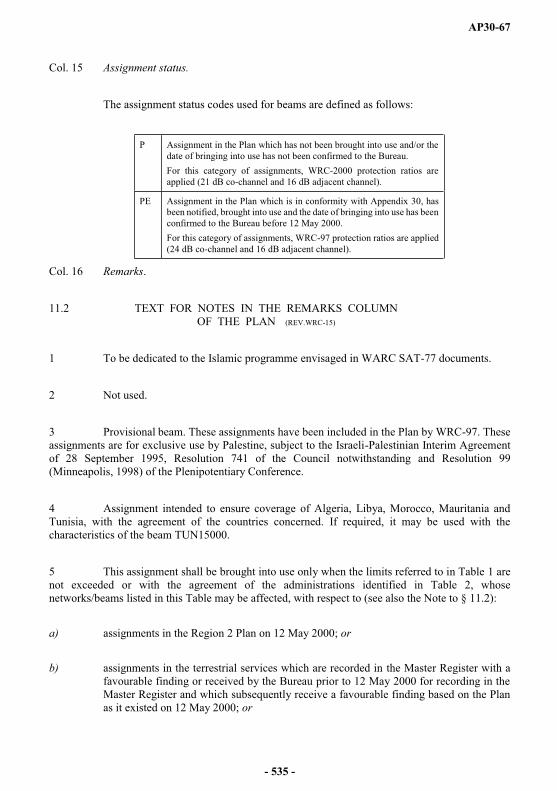
AP30-67
Col. 15 Assignment status.
The assignment status codes used for beams are defined as follows:
Col. 16 Remarks.
11.2 TEXT FOR NOTES IN THE REMARKS COLUMN OF THE PLAN (REV.WRC-15)
1 To be dedicated to the Islamic programme envisaged in WARC SAT-77 documents.
2 Not used.
3 Provisional beam. These assignments have been included in the Plan by WRC-97. These assignments are for exclusive use by Palestine, subject to the Israeli-Palestinian Interim Agreement of 28 September 1995, Resolution 741 of the Council notwithstanding and Resolution 99(Minneapolis, 1998) of the Plenipotentiary Conference.
4 Assignment intended to ensure coverage of Algeria, Libya, Morocco, Mauritania and Tunisia, with the agreement of the countries concerned. If required, it may be used with the characteristics of the beam TUN15000.
5 This assignment shall be brought into use only when the limits referred to in Table 1 are not exceeded or with the agreement of the administrations identified in Table 2, whose networks/beams listed in this Table may be affected, with respect to (see also the Note to § 11.2):
a) assignments in the Region 2 Plan on 12 May 2000; or
b) assignments in the terrestrial services which are recorded in the Master Register with a favourable finding or received by the Bureau prior to 12 May 2000 for recording in the Master Register and which subsequently receive a favourable finding based on the Plan as it existed on 12 May 2000; or
P Assignment in the Plan which has not been brought into use and/or the date of bringing into use has not been confirmed to the Bureau.For this category of assignments, WRC-2000 protection ratios are applied (21 dB co-channel and 16 dB adjacent channel).
PE Assignment in the Plan which is in conformity with Appendix 30, has been notified, brought into use and the date of bringing into use has been confirmed to the Bureau before 12 May 2000. For this category of assignments, WRC-97 protection ratios are applied (24 dB co-channel and 16 dB adjacent channel).
- 535 -
AP30-68
c) assignments in the fixed-satellite service which:
are recorded in the Master Register prior to 12 May 2000 with a favourable finding; or
have been coordinated under the provisions of No. 9.7 (or No. 1060) or § 7.2.1 of Article 7prior to 12 May 2000; or
are in process of coordination under the provisions of No. 9.7 (or No. 1060) or § 7.2.1 of Article 7 prior to 31 July 2000 for which complete Appendix 4 data (or Appendix 3 data, as appropriate) have been received by the Bureau under the relevant provisions of Article 9 (or Article 11, as appropriate):
filings received by the Bureau prior to 12 May 2000 at 1700 h (Istanbul time) shall be taken into account in the pertinent compatibility analysis by applying the pfd criteria referred to in Table 1; or
filings received by the Bureau after 12 May 2000 at 1700 h (Istanbul time), but before 31 July 2000, shall be taken into account by applying the sharing criteria of
138 dB(W/(m2 · 27 MHz)) or the pfd criteria referred to in Table 1, whichever is higher.
6 This assignment shall not claim protection from interference caused by the assignments which pertain to networks/beams identified in Table 3 which are in conformity with the Region 2 Plan on 12 May 2000 (see also the Note to § 11.2).
7 This assignment shall not claim protection from interference caused by assignments in the fixed-satellite service which pertain to networks/beams identified in Table 3 (see also the Note to § 11.2) and:
a) either are recorded in the Master Register with a favourable finding prior to 12 May 2000;
b) or for which complete Appendix 4 data (or Appendix 3 data, as appropriate) under the relevant provisions of Article 9 (or No. 1060, or § 7.2.1 of Article 7, as appropriate) have been received prior to 12 May 2000, which have been brought into use prior to 12 May 2000 and for which the complete due diligence information, in accordance with Annex 2to Resolution 49 (Rev.WRC-15), has been received prior to 12 May 2000. (WRC-15)
- 536 -
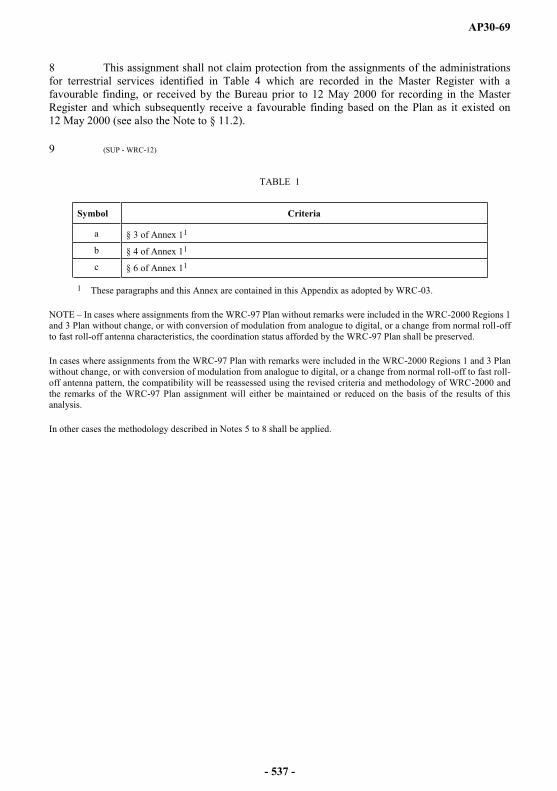
AP30-69
8 This assignment shall not claim protection from the assignments of the administrations for terrestrial services identified in Table 4 which are recorded in the Master Register with a favourable finding, or received by the Bureau prior to 12 May 2000 for recording in the Master Register and which subsequently receive a favourable finding based on the Plan as it existed on 12 May 2000 (see also the Note to § 11.2).
9 (SUP - WRC-12)
TABLE 1
Symbol Criteria
a § 3 of Annex 11
b § 4 of Annex 11
c § 6 of Annex 11
1 These paragraphs and this Annex are contained in this Appendix as adopted by WRC-03.
NOTE In cases where assignments from the WRC-97 Plan without remarks were included in the WRC-2000 Regions 1and 3 Plan without change, or with conversion of modulation from analogue to digital, or a change from normal roll-offto fast roll-off antenna characteristics, the coordination status afforded by the WRC-97 Plan shall be preserved.
In cases where assignments from the WRC-97 Plan with remarks were included in the WRC-2000 Regions 1 and 3 Plan without change, or with conversion of modulation from analogue to digital, or a change from normal roll-off to fast roll-off antenna pattern, the compatibility will be reassessed using the revised criteria and methodology of WRC-2000 and the remarks of the WRC-97 Plan assignment will either be maintained or reduced on the basis of the results of this analysis.
In other cases the methodology described in Notes 5 to 8 shall be applied.
- 537 -
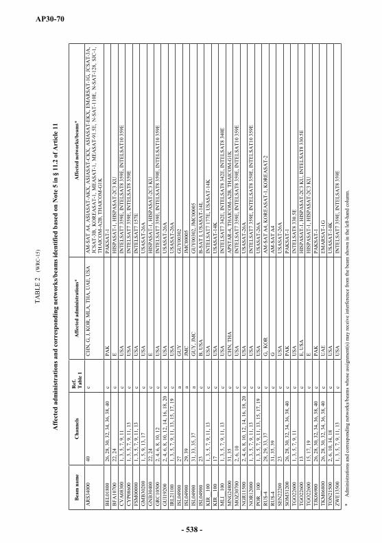
AP30-70
TAB
LE 2
(W
RC
-15)
Aff
ecte
d ad
min
istra
tions
and
cor
resp
ondi
ng n
etw
orks
/bea
ms i
dent
ified
bas
ed o
n N
ote
5 in
§ 1
1.2
of A
rtic
le 1
1
Bea
m n
ame
Cha
nnel
sR
ef.
Tab
le 1
Aff
ecte
d ad
min
istr
atio
ns*
Aff
ecte
d ne
twor
ks/b
eam
s*
AR
S340
0040
cC
HN
, G, J
, KO
R, M
LA, T
HA
, UA
E, U
SAA
M-S
AT
A4,
ASI
ASA
T-A
KX
, ASI
ASA
T-C
KX
, ASI
ASA
T-EK
X, E
MA
RSA
T-1G
, JC
SAT-
3A,
JCSA
T-3B
, K
OR
EASA
T-1,
MEA
SAT-
1, M
EASA
T-91
.5E,
N-S
AT-
110E
, N
-SA
T-12
8, S
JC-1
, TH
AIC
OM
-A2B
, TH
AIC
OM
-G1K
BEL
0180
026
, 28,
30,
32,
34,
36,
38,
40
cPA
KPA
KSA
T-1
BFA
1070
022
, 24
cE
HIS
PASA
T-1,
HIS
PASA
T-2C
3 K
UC
VA
0830
01,
3, 5
, 7, 9
, 11
cU
SAIN
TELS
AT7
359
E, IN
TELS
AT8
359
E, IN
TELS
AT1
0 35
9EC
YP0
8600
1, 3
, 5, 7
, 9, 1
1, 1
3c
USA
INTE
LSA
T7 3
59E,
INTE
LSA
T8 3
59E
FSM
0000
01,
3, 5
, 7, 9
, 11,
13
cU
SAIN
TELS
AT7
157
EG
MB
3020
01,
5, 9
, 13,
17
cU
SAU
SASA
T-26
AG
NB
3040
022
, 24
cE
HIS
PASA
T-1,
HIS
PASA
T-2C
3 K
UG
RC
1050
02,
4, 6
, 8, 1
0, 1
2c
USA
INTE
LSA
T7 3
59E,
INTE
LSA
T8 3
59E,
INTE
LSA
T10
359E
GU
I192
002,
4, 6
, 8, 1
0, 1
2, 1
4, 1
6, 1
8, 2
0c
USA
USA
SAT-
26A
IRL2
1100
1, 3
, 5, 7
, 9, 1
1, 1
3, 1
5, 1
7, 1
9c
USA
USA
SAT-
26A
ISL0
4900
27a
GU
YG
UY
0030
2IS
L049
0029
, 39
aJM
CJM
C00
005
ISL0
4900
31, 3
3, 3
5, 3
7a
GU
Y, J
MC
GU
Y00
302,
JMC
0000
5IS
L049
0023
cB
, USA
B-S
AT
I, U
SASA
T-14
LK
IR__
100
1, 3
, 5, 7
, 9, 1
1, 1
3c
USA
INTE
LSA
T7 1
77E,
USA
SAT-
14K
KIR
__10
017
cU
SAU
SASA
T-14
KM
LI__
100
1, 3
, 5, 7
, 9, 1
1, 1
3c
USA
INTE
LSA
T7 3
42E,
INTE
LSA
T8 3
42E,
INTE
LSA
T8 3
40E
MN
G24
800
31, 3
5 c
CH
N, T
HA
APS
TAR
-4, T
HA
ICO
M-A
2B, T
HA
ICO
M-G
1KM
OZ3
0700
2, 6
, 10
cU
SAIN
TELS
AT7
359
E, IN
TELS
AT8
359
E, IN
TELS
AT1
0 35
9EN
GR
1150
02,
4, 6
, 8, 1
0, 1
2, 1
4, 1
6, 1
8, 2
0c
USA
USA
SAT-
26A
NO
R12
000
1, 3
, 5, 7
, 9, 1
1, 1
3c
USA
INTE
LSA
T735
9E, I
NTE
LSA
T8 3
59E,
INTE
LSA
T10
359E
POR
__10
01,
3, 5
, 7, 9
, 11,
13,
15,
17,
19
cU
SAU
SASA
T-26
AR
US-
428
, 29,
33,
37
cG
, K
OR
AM
-SA
T A
4, K
OR
EASA
T-1,
KO
REA
SAT-
2R
US-
431
, 35,
39
cG
AM
-SA
T A
4SE
N22
200
23c
USA
USA
SAT-
26A
SOM
3120
026
, 28,
30,
32,
34,
36,
38,
40
cPA
KPA
KSA
T-1
TGO
2260
01,
3, 5
, 7, 9
, 11
cU
SAIN
TELS
AT8
330
.5E
TGO
2260
013
cE,
USA
HIS
PASA
T-1,
HIS
PASA
T-2C
3 K
U, I
NTE
LSA
T8 3
30.5
ETG
O22
600
15, 1
7, 1
9c
EH
ISPA
SAT-
1, H
ISPA
SAT-
2C3
KU
TJK
0690
026
, 28,
30,
32,
34,
36,
38,
40
cPA
KPA
KSA
T-1
TKM
0680
026
, 28,
30,
32,
34,
36,
38,
40
cU
AE
EMA
RSA
T-1G
TON
2150
02,
6, 1
0, 1
4, 1
8c
USA
USA
SAT-
14K
ZWE1
3500
1, 3
, 5, 7
, 9, 1
1, 1
3c
USA
INTE
LSA
T7 3
59E,
INTE
LSA
T8 3
59E
*A
dmin
istra
tions
and
cor
resp
ondi
ng n
etw
orks
/bea
ms w
hose
ass
ignm
ent(s
) may
rece
ive
inte
rfere
nce
from
the
beam
show
n in
the
left-
hand
col
umn.
- 538 -
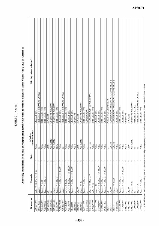
AP30-71
TAB
LE 3
(WR
C-1
5)
Aff
ectin
g ad
min
istr
atio
ns a
nd c
orre
spon
ding
net
wor
ks/b
eam
s ide
ntifi
ed b
ased
on
Not
es 6
and
7 in
§ 1
1.2
of A
rtic
le 1
1
Bea
m n
ame
Cha
nnel
sN
ote
Aff
ectin
g ad
min
istr
atio
ns*
Aff
ectin
g ne
twor
ks/b
eam
s*
AN
D34
100
2, 6
, 10,
12,
14,
16,
18,
20
7U
SAU
SASA
T-26
AB
FA10
700
22, 2
47
EH
ISPA
SAT-
1, H
ISPA
SAT-
2C3
KU
CV
A08
300
1, 3
, 5, 7
, 9, 1
17
USA
INTE
LSA
T7 3
59E
CY
P086
001,
3, 5
, 7, 9
, 11,
13
7U
SAIN
TELS
AT7
359
ED
NK
090X
R29
6JM
CJM
C000
05D
NK
090X
R33
6G
UY
, JM
CG
UY
0030
2, JM
C000
05D
NK
091X
R31
, 35
6G
UY
, JM
CG
UY
0030
2, JM
C000
05FJ
I193
001,
3, 5
, 7, 9
, 11,
13
7H
OL
INTE
LSA
T7 1
83E
GM
B30
200
1, 3
, 5, 7
, 9, 1
1, 1
3, 1
5, 1
7, 1
97
USA
USA
SAT-
26A
GN
B30
400
22, 2
47
EH
ISPA
SAT-
1, H
ISPA
SAT-
2C3
KU
GR
C10
500
2, 4
, 6, 8
, 10,
12
7U
SAIN
TELS
AT7
359
EG
UI1
9200
2, 4
, 6, 8
, 10,
12,
14,
16,
18,
20
7U
SAU
SASA
T-26
AIR
L211
001,
3, 5
, 7, 9
, 11,
13,
15,
17,
19
7U
SAU
SASA
T-26
AIS
L049
0027
6G
UY
GU
Y00
302
ISL0
4900
29, 3
96
JMC
JMC
0000
5IS
L049
0031
, 33,
35,
37
6G
UY
,JM
CG
UY
0030
2, JM
C00
005
KIR
__10
01,
3, 5
, 7, 9
, 11,
13
7U
SAIN
TELS
AT7
177
EM
NG
2480
027
7J
SUPE
RB
IRD
-CM
NG
2480
029
, 31,
33,
35,
37,
39
7J,
THA
THA
ICO
M-A
2B, S
UPE
RB
IRD
-CM
OZ3
0700
2, 6
, 10,
12
7U
SAIN
TELS
AT7
359
EM
TN__
100
22, 2
4, 2
67
USA
USA
SAT-
26A
NG
R11
500
2, 4
, 6, 8
, 10,
12,
14,
16,
18,
20
7U
SAU
SASA
T-26
AN
OR
1200
01,
3, 5
, 7, 9
, 11,
13
7U
SAIN
TELS
AT7
359
EPO
R__
100
1, 3
, 5, 7
, 9, 1
1, 1
3, 1
5, 1
7, 1
97
USA
USA
SAT-
26A
RU
S-4
257
JJC
SAT-
1R, S
UPE
RB
IRD
-CR
US-
428
, 29
7J,
KO
RSU
PER
BIR
D-C
, KO
REA
SAT-
1, K
OR
EASA
T-2
RU
S-4
31, 3
3, 3
5, 3
7, 3
97
J, K
OR
SUPE
RB
IRD
-C, K
OR
EASA
T-1,
KO
REA
SAT-
2SE
N22
200
23, 2
57
USA
USA
SAT-
26A
SMO
0570
01,
3, 5
, 7, 9
, 11,
13
7H
OL
INTE
LSA
T7 1
83E
SMR
3110
01,
3, 5
, 7, 9
, 11,
13,
15,
17,
19
7U
SAU
SASA
T-26
ASR
L259
0027
6G
UY
GU
Y00
302
SRL2
5900
29, 3
96
JMC
JMC0
0005
SRL2
5900
31, 3
3, 3
5, 3
76
GU
Y, J
MC
GU
Y00
302,
JMC
0000
5TG
O22
600
137
EH
ISPA
SAT-
2C3
KU
TGO
2260
015
, 17,
19
7E
HIS
PASA
T-1,
HIS
PASA
T-2C
3 K
UZW
E135
001,
3, 5
, 7, 9
, 11,
13
7U
SAIN
TELS
AT7
359
E
*A
dmin
istra
tions
and
corre
spon
ding
net
wor
ks/b
eam
s who
se a
ssig
nmen
t(s) m
ay c
ause
inte
rfere
nce
to th
e be
am sh
own
in th
e le
ft-ha
nd c
olum
n.
- 539 -
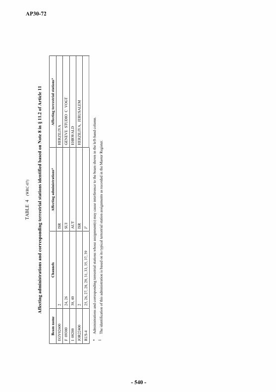
AP30-72
TAB
LE 4
(WR
C-0
7)
Aff
ectin
g ad
min
istr
atio
ns a
nd c
orre
spon
ding
terr
estr
ial s
tatio
ns id
entif
ied
base
d on
Not
e 8
in §
11.
2 of
Art
icle
11
Bea
m n
ame
Cha
nnel
sA
ffec
ting
adm
inis
trat
ions
*A
ffec
ting
terr
estr
ial s
tatio
ns*
EGY
0260
02
ISR
HER
ZILI
YA
F 0
9300
24, 2
6SU
IG
ENEV
E S
TUD
IO C
VO
GT
I 08
200
38, 4
0A
UT
EHR
WA
LD
JOR
2240
02
ISR
HER
ZILI
YA
, JE
RU
SALE
M
RU
S-4
25, 2
6, 2
7, 2
8, 2
9, 3
1, 3
3, 3
5, 3
7, 3
9J1
*A
dmin
istra
tions
and
cor
resp
ondi
ng te
rrest
rial s
tatio
ns w
hose
ass
ignm
ent(s
) may
cau
se in
terfe
renc
e to
the
beam
show
n in
the
left-
hand
col
umn.
1Th
e id
entif
icat
ion
of th
is a
dmin
istra
tion
is ba
sed
on it
s typ
ical
terre
stria
l sta
tion
assig
nmen
ts a
s rec
orde
d in
the
Mas
ter R
egis
ter.
- 540 -
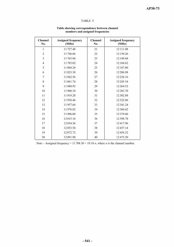
AP30-73
TABLE 5
Table showing correspondence between channel numbers and assigned frequencies
ChannelNo.
Assigned frequency(MHz)
ChannelNo.
Assigned frequency(MHz)
1 11 727.48 21 12 111.082 11 746.66 22 12 130.263 11 765.84 23 12 149.444 11 785.02 24 12 168.625 11 804.20 25 12 187.806 11 823.38 26 12 206.987 11 842.56 27 12 226.168 11 861.74 28 12 245.349 11 880.92 29 12 264.5210 11 900.10 30 12 283.7011 11 919.28 31 12 302.8812 11 938.46 32 12 322.0613 11 957.64 33 12 341.2414 11 976.82 34 12 360.4215 11 996.00 35 12 379.6016 12 015.18 36 12 398.7817 12 034.36 37 12 417.9618 12 053.54 38 12 437.1419 12 072.72 39 12 456.3220 12 091.90 40 12 475.50
Note Assigned frequency = 11 708.30 + 19.18 n, where n is the channel number.
- 541 -
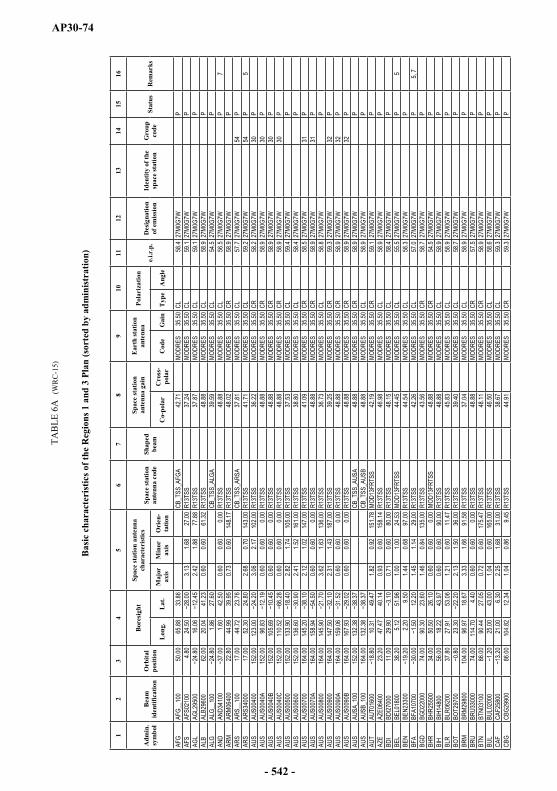
AP30-74
TAB
LE 6
A(W
RC
-15)
Bas
ic c
hara
cter
istic
s of t
he R
egio
ns 1
and
3 P
lan
(sor
ted
by a
dmin
istr
atio
n)
12
34
56
78
910
1112
1314
1516
Adm
in.
sym
bol
Bea
mid
entif
icat
ion
Orb
ital
posi
tion
Bor
esig
htSp
ace
stat
ion
ante
nna
char
acte
rist
ics
Spac
e st
atio
nan
tenn
a co
deSh
aped
beam
Spac
e st
atio
nan
tenn
a ga
inE
arth
stat
ion
ante
nna
Pola
riza
tion
e.i.r
.p.
Des
igna
tion
of e
mis
sion
Iden
tity
of th
e sp
ace
stat
ion
Gro
upco
deSt
atus
Rem
arks
Lon
g.L
at.
Maj
orax
isM
inor
axis
Ori
en-
tatio
nC
o-po
lar
Cro
ss-
pola
rC
ode
Gai
nT
ype
Ang
le
AFG
AFG_
_100
50.00
65.88
33.86
CB_T
SS_A
FGA
42.71
MODR
ES
35.50
CL58
.427
M0G
7W
PAF
SAF
S021
004.8
024
.503.1
31.6
827
.00R1
3TSS
37.24
MODR
ES
35.50
CL59
.127
M0G
7W
PAG
LAG
L295
0016
.062.4
21.8
877
.88R1
3TSS
37.87
MODR
ES
35.50
CL59
.127
M0G
7W
PAL
BAL
B296
0062
.0020
.0441
.230.6
00.6
061
.32R1
3TSS
48.88
MODR
ES
35.50
CL58
.927
M0G
7W
PAL
GAL
G__1
001.8
627
.60CB
_TSS
_ALG
A 39
.59MO
DRES
35
.50CL
54.5
27M
0G7W
P
AND
AND3
4100
1.60
42.50
0.60
0.60
0.00
R13T
SS
48
.88MO
DRES
35
.50CL
56.5
27M
0G7W
P
7AR
MAR
M064
0022
.8044
.9939
.950.7
30.6
014
8.17
R13T
SS
48
.02MO
DRES
35
.50CR
58.9
27M
0G7W
P
ARS
ARS_
_100
17.00
44.72
23.76
CB_T
SS_A
RSA
37.81
MODR
ES
35.50
CL57
.727
M0G
7W
54P
ARS
ARS3
4000
17.00
52.30
24.80
2.68
0.70
143.0
0R1
3TSS
41.71
MODR
ES
35.50
CL59
.227
M0G
7W
54P
5AU
SAU
S004
0015
2.00
123.0
03.0
62.1
710
2.00
R13T
SS
36
.22MO
DRES
35
.50CR
58.2
27M
0G7W
30
PAU
SAU
S004
0A15
2.00
96.83
0.60
0.60
0.00
R13T
SS
48
.88MO
DRES
35
.50CR
58.9
27M
0G7W
30
PAU
SAU
S004
0B15
2.00
105.6
90.6
00.6
00.0
0R1
3TSS
48.88
MODR
ES
35.50
CR58
.927
M0G
7W
30P
AUS
AUS0
040C
152.0
011
0.52
0.60
0.60
0.00
R13T
SS
48
.88MO
DRES
35
.50CR
58.9
27M
0G7W
30
PAU
SAU
S005
0015
2.00
133.9
02.8
21.7
410
5.00
R13T
SS
37
.53MO
DRES
35
.50CL
59.4
27M
0G7W
P
AUS
AUS0
0600
152.0
013
6.60
2.41
1.52
161.0
0R1
3TSS
38.80
MODR
ES
35.50
CL58
.427
M0G
7W
PAU
SAU
S007
0016
4.00
145.2
02.1
21.0
214
7.00
R13T
SS
41
.09MO
DRES
35
.50CR
58.5
27M
0G7W
31
PAU
SAU
S007
0A16
4.00
158.9
40.6
00.6
00.0
0R1
3TSS
48.88
MODR
ES
35.50
CR58
.927
M0G
7W
31P
AUS
AUS0
0800
164.0
014
5.90
3.62
1.63
136.0
0R1
3TSS
36.73
MODR
ES
35.50
CL58
.827
M0G
7W
PAU
SAU
S009
0016
4.00
147.5
02.3
11.4
318
7.00
R13T
SS
39
.25MO
DRES
35
.50CR
59.3
27M
0G7W
32
PAU
SAU
S009
0A16
4.00
159.0
60.6
00.6
00.0
0R1
3TSS
48.88
MODR
ES
35.50
CR58
.927
M0G
7W
32P
AUS
AUS0
090B
164.0
016
7.93
0.60
0.60
0.00
R13T
SS
48
.88MO
DRES
35
.50CR
58.9
27M
0G7W
32
PAU
SAU
SA_1
0015
2.00
132.3
8CB
_TSS
_AUS
A 48
.88MO
DRES
35
.50CR
58.9
27M
0G7W
P
AUS
AUSB
_100
164.0
013
2.38
CB_T
SS_A
USB
48.88
MODR
ES
35.50
CL58
.927
M0G
7W
PAU
TAU
T016
0010
.3149
.471.8
20.9
215
1.78
MOD1
3FRT
SS
42.19
MODR
ES
35.50
CR59
.127
M0G
7W
PAZ
EAZ
E064
0023
.2047
.4740
.140.9
30.6
015
8.14
R13T
SS
46
.98MO
DRES
35
.50CL
58.9
27M
0G7W
PBD
IBD
I2700
011
.0029
.900.7
10.6
080
.00R1
3TSS
48.15
MODR
ES
35.50
CL58
.427
M0G
7W
PBE
LBE
L018
0038
.205.1
251
.961.0
01.0
024
.53MO
D13F
RTSS
44
.45MO
DRES
35
.50CL
55.5
27M
0G7W
P
5BE
NBE
N233
002.2
09.5
01.4
40.6
897
.00R1
3TSS
44.54
MODR
ES
35.50
CL58
.327
M0G
7W
PBF
ABF
A107
0012
.201.4
51.1
429
.00R1
3TSS
42.26
MODR
ES
35.50
CL57
.027
M0G
7W
P5,
7BG
DBG
D220
0074
.0090
.3023
.601.4
60.8
413
5.00
R13T
SS
43
.56MO
DRES
35
.50CR
58.7
27M
0G7W
P
BHR
BHR2
5500
34.00
50.50
26.10
0.60
0.60
0.00
MOD1
3FRT
SS
48.88
MODR
ES
35.50
CR54
.527
M0G
7W
PBI
HBI
H148
0056
.0018
.2243
.970.6
00.6
090
.00R1
3TSS
48.88
MODR
ES
35.50
CL58
.927
M0G
7W
PBL
RBL
R062
0037
.8027
.9153
.061.2
10.6
011
.47R1
3TSS
45.83
MODR
ES
35.50
CL58
.927
M0G
7W
PBO
TBO
T297
0023
.302.1
31.5
036
.00R1
3TSS
39.40
MODR
ES
35.50
CL58
.727
M0G
7W
PBR
MBR
M298
0010
4.00
96.97
18.67
3.33
1.66
91.58
R13T
SS
37
.04MO
DRES
35
.50CL
58.9
27M
0G7W
P
BRU
BRU3
3000
74.00
114.7
04.4
00.6
00.6
00.0
0R1
3TSS
48.88
MODR
ES
35.50
CR57
.527
M0G
7W
PBT
NBT
N031
0086
.0090
.4427
.050.7
20.6
017
5.47
R13T
SS
48
.11MO
DRES
35
.50CR
58.9
27M
0G7W
P
BUL
BUL0
2000
25.00
43.00
1.04
0.60
165.0
0R1
3TSS
46.50
MODR
ES
35.50
CL58
.627
M0G
7W
PCA
FCA
F258
0021
.006.3
02.2
51.6
831
.00R1
3TSS
38.67
MODR
ES
35.50
CL59
.327
M0G
7W
PCB
GCB
G299
0086
.0010
4.82
12.34
1.04
0.86
9.45
R13T
SS
44
.91MO
DRES
35
.50CR
59.3
27M
0G7W
P
- 542 -

AP30-75
12
34
56
78
910
1112
1314
1516
Adm
in.
sym
bol
Bea
mid
entif
icat
ion
Orb
ital
posi
tion
Bor
esig
htSp
ace
stat
ion
ante
nna
char
acte
rist
ics
Spac
e st
atio
nan
tenn
a co
deSh
aped
beam
Spac
e st
atio
nan
tenn
a ga
inE
arth
stat
ion
ante
nna
Pola
riza
tion
e.i.r
.p.
Des
igna
tion
of e
mis
sion
Iden
tity
of th
e sp
ace
stat
ion
Gro
upco
deSt
atus
Rem
arks
Lon
g.L
at.
Maj
orax
isM
inor
axis
Ori
en-
tatio
nC
o-po
lar
Cro
ss-
pola
rC
ode
Gai
nT
ype
Ang
le
CHN
CHN1
5500
62.00
88.18
31.20
3.03
1.24
163.2
3R1
3TSS
38.69
MODR
ES
35.50
CL57
.927
M0G
7W
PCH
NCH
N158
0013
4.00
113.2
939
.702.8
01.5
535
.44R1
3TSS
38.07
MODR
ES
35.50
CR57
.027
M0G
7W
PCH
NCH
N190
0012
2.00
114.1
723
.320.9
10.6
02.8
8MO
D13F
RTSS
47
.08MO
DRES
35
.50CR
58.9
27M
0G7W
P
CHN
CHN2
0000
122.0
011
3.55
22.20
0.60
0.60
0.00
MOD1
3FRT
SS
48.88
MODR
ES
35.50
CL57
.027
M0G
7W
PCH
NCH
NA_1
0062
.0090
.5639
.22CB
_TSS
_CHN
A 40
.01MO
DRES
35
.50CR
58.5
27M
0G7W
P
CHN
CHNC
_100
134.0
010
5.77
27.56
CB_T
SS_C
HNC
39.51
MODR
ES
35.50
CL57
.127
M0G
7W
PCH
NCH
NE_1
0092
.2011
4.96
20.16
CB_T
SS_C
HNE
44.74
MODR
ES
35.50
CL59
.427
M0G
7W
PCH
NCH
NF_1
0092
.2012
3.54
45.78
CB_T
SS_C
HNF
43.71
MODR
ES
35.50
CR60
.427
M0G
7W
PCL
NCL
N219
0050
.0080
.607.7
01.1
80.6
010
6.00
R13T
SS
45
.95MO
DRES
35
.50CL
56.7
27M
0G7W
P
CME
CME3
0000
12.70
6.20
2.54
1.68
87.00
R13T
SS
38
.15MO
DRES
35
.50CR
58.5
27M
0G7W
P
COD
COD_
_100
21.85
CB_T
SS_C
ODA
38.36
MODR
ES
35.50
CR59
.727
M0G
7W
PCO
GCO
G235
0014
.602.0
21.1
859
.00R1
3TSS
40.67
MODR
ES
35.50
CL58
.827
M0G
7W
PCO
MCO
M207
0029
.0044
.100.7
60.6
014
9.00
R13T
SS
47
.86MO
DRES
35
.50CR
58.1
27M
0G7W
P
CPV
CPV3
0100
16.09
0.77
0.63
94.46
R13T
SS
47
.56MO
DRES
35
.50CL
57.2
27M
0G7W
P
CTI
CTI23
700
7.19
1.50
1.26
111.7
4R1
3TSS
41.67
MODR
ES
35.50
CL58
.827
M0G
7W
PCV
ACV
A083
0013
.0242
.090.7
50.6
620
.53R1
3TSS
47.50
MODR
ES
35.50
CR60
.227
M0G
7W
P5,
7CV
ACV
A085
0012
.5941
.091.7
21.3
114
4.13
MOD1
3FRT
SS
40.92
MODR
ES
35.50
CR56
.527
M0G
7W
PCY
PCY
P086
0033
.4535
.120.6
00.6
00.0
0MO
D13F
RTSS
48
.88MO
DRES
35
.50CR
56.1
27M
0G7W
P
5, 7
CZE
CZE1
4401
16.77
46.78
1.71
0.89
149.1
5MO
D13F
RTSS
42
.64MO
DRES
35
.50CL
58.8
27M
0G7W
P
CZE
CZE1
4402
16.77
46.78
1.71
0.89
149.1
5MO
D13F
RTSS
42
.64MO
DRES
35
.50CR
58.8
27M
0G7W
P
CZE
CZE1
4403
16.77
46.78
1.71
0.89
149.1
5MO
D13F
RTSS
42
.64MO
DRES
35
.50CR
58.8
27M
0G7W
37
PD
D
0870
010
.3149
.471.8
20.9
215
1.78
MOD1
3FRT
SS
42.19
MODR
ES
35.50
CR59
.127
M0G
7W
PDJ
IDJ
I0990
016
.8042
.6811
.680.6
00.6
090
.00R1
3TSS
48.88
MODR
ES
35.50
CL57
.527
M0G
7W
PDN
KDN
K__1
002.9
259
.62CB
_TSS
_DNK
A 48
.88MO
DRES
35
.50CL
58.3
27M
0G7W
P
DNK
DNK0
90XR
13.27
60.86
1.99
0.63
151.3
8MO
D13F
RTSS
43
.48MO
DRES
35
.50CR
54.5
27M
0G7W
P
6DN
KDN
K091
XR63
.671.5
60.6
017
0.63
MOD1
3FRT
SS
44.73
MODR
ES
35.50
CR58
.627
M0G
7W
P6
E
E___
_100
34.15
CB_T
SS_E
__A
44.79
MODR
ES
35.50
CL58
.927
M0G
7W
01P
E
HISP
33D1
39.00
COP
39.80
5.50
MODR
ES
35.50
CL57
.633
M0G
7W--
HISP
ASAT
-101
PEE
HI
SP33
D239
.00CO
P39
.805.5
0MO
DRES
32
.50CL
57.6
33M
0G7W
--HI
SPAS
AT-1
01PE
E
HISP
A27D
39.00
COP
39.80
5.50
MODR
ES
38.43
CL57
.627
M0G
7W--
HISP
ASAT
-101
PEE
HI
SPAS
A439
.00CO
P39
.805.5
0MO
DRES
38
.43CL
57.6
27M
0F8W
HI
SPAS
AT-1
01PE
EGY
EGY0
2600
29.70
26.80
2.33
1.72
136.0
0R1
3TSS
38.42
MODR
ES
35.50
CL58
.127
M0G
7W
12P
8ER
IER
I0920
022
.8039
.4114
.981.6
70.9
514
5.48
R13T
SS
42
.44MO
DRES
35
.50CR
58.9
27M
0G7W
P
EST
EST0
6100
44.50
25.06
58.60
0.77
0.60
12.27
R13T
SS
47
.81MO
DRES
35
.50CR
58.7
27M
0G7W
P
ETH
ETH0
9200
36.00
40.29
8.95
2.87
2.16
174.0
6R1
3TSS
36.52
MODR
ES
35.50
CL58
.727
M0G
7W
PF
F
0930
03.5
245
.412.2
21.1
515
9.34
R13T
SS
40
.39MO
DRES
35
.50CL
58.8
27M
0G7W
21
P8
F
F___
_100
50.00
CB_T
SS_F
__A
48.88
MODR
ES
35.50
CR58
.927
M0G
7W
PF
NC
L100
0014
0.00
166.0
01.1
40.7
214
6.00
R13T
SS
45
.30MO
DRES
35
.50CR
58.7
27M
0G7W
P
F
OCE1
0100
4.34
3.54
4.00
R13T
SS
32
.58MO
DRES
35
.50CL
58.5
27M
0G7W
P
F
WAL
1020
014
0.00
0.74
0.60
29.00
R13T
SS
47
.97MO
DRES
35
.50CR
59.4
27M
0G7W
P
FIN
FIN1
0300
22.80
22.50
64.50
1.38
0.76
171.0
0MO
D13F
RTSS
44
.24MO
DRES
35
.50CL
54.5
27M
0G7W
52
PFI
NFI
N104
0022
.8015
.8761
.152.2
40.9
116
.70MO
D13F
RTSS
41
.37MO
DRES
35
.50CL
54.5
27M
0G7W
52
PFJ
IFJ
I1930
017
9.62
1.16
0.92
155.2
2R1
3TSS
44.16
MODR
ES
35.50
CR58
.727
M0G
7W
P7
FSM
FSM0
0000
158.0
015
1.90
5.48
5.15
1.57
167.0
0R1
3TSS
35.38
MODR
ES
35.50
CR58
.927
M0G
7W
P5
G
G 02
700
53.80
1.84
0.72
142.0
0R1
3TSS
43.23
MODR
ES
35.50
CR58
.027
M0G
7W
P
- 543 -
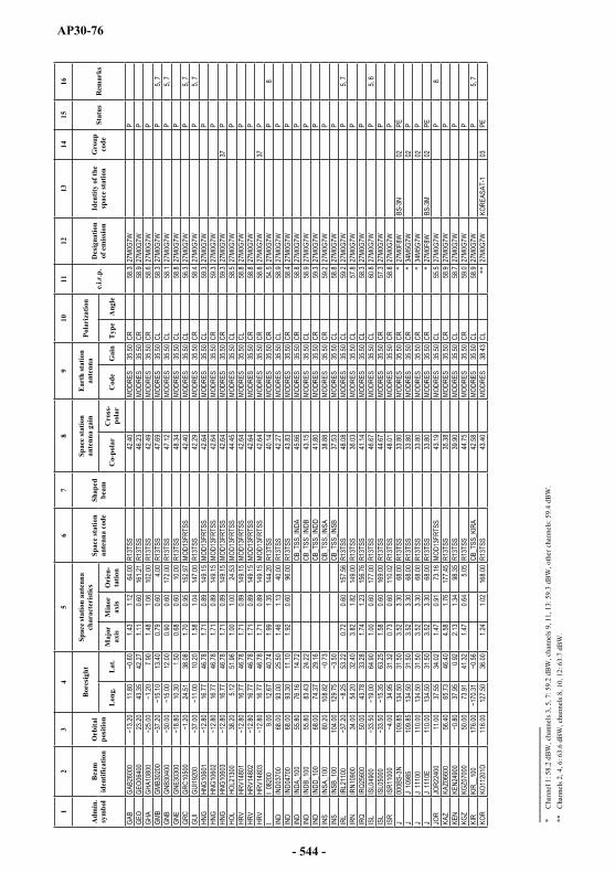
AP30-76
12
34
56
78
910
1112
1314
1516
Adm
in.
sym
bol
Bea
mid
entif
icat
ion
Orb
ital
posi
tion
Bor
esig
htSp
ace
stat
ion
ante
nna
char
acte
rist
ics
Spac
e st
atio
nan
tenn
a co
deSh
aped
beam
Spac
e st
atio
nan
tenn
a ga
inE
arth
stat
ion
ante
nna
Pola
riza
tion
e.i.r
.p.
Des
igna
tion
of e
mis
sion
Iden
tity
of th
e sp
ace
stat
ion
Gro
upco
deSt
atus
Rem
arks
Lon
g.L
at.
Maj
orax
isM
inor
axis
Ori
en-
tatio
nC
o-po
lar
Cro
ss-
pola
rC
ode
Gai
nT
ype
Ang
le
GAB
GAB2
6000
11.80
1.43
1.12
64.00
R13T
SS
42
.40MO
DRES
35
.50CR
58.3
27M
0G7W
P
GEO
GEO0
6400
23.20
43.35
42.27
1.11
0.60
161.2
1R1
3TSS
46.23
MODR
ES
35.50
CR58
.927
M0G
7W
PGH
AGH
A108
007.9
01.4
81.0
610
2.00
R13T
SS
42
.49MO
DRES
35
.50CR
58.6
27M
0G7W
P
GMB
GMB3
0200
13.40
0.79
0.60
4.00
R13T
SS
47
.69MO
DRES
35
.50CL
58.3
27M
0G7W
P
5, 7
GNB
GNB3
0400
12.00
0.90
0.60
172.0
0R1
3TSS
47.12
MODR
ES
35.50
CL58
.127
M0G
7W
P5,
7GN
EGN
E303
0010
.301.5
00.6
80.6
010
.00R1
3TSS
48.34
MODR
ES
35.50
CL58
.827
M0G
7W
PGR
CGR
C105
0024
.5138
.081.7
00.9
515
2.97
MOD1
3FRT
SS
42.40
MODR
ES
35.50
CL56
.327
M0G
7W
P5,
7GU
IGU
I1920
010
.201.5
81.0
414
7.00
R13T
SS
42
.29MO
DRES
35
.50CR
58.4
27M
0G7W
P
5, 7
HNG
HNG1
0601
16.77
46.78
1.71
0.89
149.1
5MO
D13F
RTSS
42
.64MO
DRES
35
.50CL
59.3
27M
0G7W
P
HNG
HNG1
0602
16.77
46.78
1.71
0.89
149.1
5MO
D13F
RTSS
42
.64MO
DRES
35
.50CR
59.3
27M
0G7W
P
HNG
HNG1
0603
16.77
46.78
1.71
0.89
149.1
5MO
D13F
RTSS
42
.64MO
DRES
35
.50CR
59.3
27M
0G7W
37
PHO
LHO
L213
0038
.205.1
251
.961.0
01.0
024
.53MO
D13F
RTSS
44
.45MO
DRES
35
.50CL
58.5
27M
0G7W
P
HRV
HRV1
4801
16.77
46.78
1.71
0.89
149.1
5MO
D13F
RTSS
42
.64MO
DRES
35
.50CL
58.8
27M
0G7W
P
HRV
HRV1
4802
16.77
46.78
1.71
0.89
149.1
5MO
D13F
RTSS
42
.64MO
DRES
35
.50CR
58.8
27M
0G7W
P
HRV
HRV1
4803
16.77
46.78
1.71
0.89
149.1
5MO
D13F
RTSS
42
.64MO
DRES
35
.50CR
58.8
27M
0G7W
37
PI
I 082
009.0
012
.6740
.741.9
91.3
514
4.20
R13T
SS
40
.14MO
DRES
35
.50CR
54.5
27M
0G7W
P
8IN
DIN
D037
0068
.0093
.0025
.501.4
61.1
340
.00R1
3TSS
42.27
MODR
ES
35.50
CL58
.927
M0G
7W
PIN
DIN
D047
0068
.0093
.3011
.101.9
20.6
096
.00R1
3TSS
43.83
MODR
ES
35.50
CR58
.427
M0G
7W
PIN
DIN
DA_1
0055
.8076
.1614
.72CB
_TSS
_INDA
45
.66MO
DRES
35
.50CR
58.8
27M
0G7W
P
IND
INDB
_100
55.80
83.43
24.22
CB_T
SS_IN
DB
43.15
MODR
ES
35.50
CL58
.927
M0G
7W
PIN
DIN
DD_1
0068
.0074
.3729
.16CB
_TSS
_INDD
41
.80MO
DRES
35
.50CR
59.3
27M
0G7W
P
INS
INSA
_100
80.20
108.8
2CB
_TSS
_INSA
38
.88MO
DRES
35
.50CR
59.2
27M
0G7W
P
INS
INSB
_100
104.0
012
9.75
CB_T
SS_IN
SB
37.53
MODR
ES
35.50
CL58
.827
M0G
7W
PIR
LIR
L211
0053
.220.7
20.6
015
7.56
R13T
SS
48
.08MO
DRES
35
.50CL
59.2
27M
0G7W
P
5, 7
IRN
IRN1
0900
34.00
54.20
32.40
3.82
1.82
149.0
0R1
3TSS
36.03
MODR
ES
35.50
CL57
.827
M0G
7W
PIR
QIR
Q256
0050
.0043
.7833
.281.7
41.2
315
6.76
R13T
SS
41
.14MO
DRES
35
.50CL
58.3
27M
0G7W
P
ISL
ISL0
4900
64.90
1.00
0.60
177.0
0R1
3TSS
46.67
MODR
ES
35.50
CL60
.827
M0G
7W
P5,
6IS
LIS
L050
0063
.251.5
80.6
016
9.00
R13T
SS
44
.67MO
DRES
35
.50CR
57.3
27M
0G7W
P
ISR
ISR1
1000
34.95
31.32
0.73
0.60
110.0
2R1
3TSS
48.01
MODR
ES
35.50
CR58
.827
M0G
7W
PJ
000B
S-3N
109.8
513
4.50
31.50
3.52
3.30
68.00
R13T
SS
33
.80MO
DRES
35
.50CR
*27
M0F
8W
BS-3
N02
PEJ
J 10
985
109.8
513
4.50
31.50
3.52
3.30
68.00
R13T
SS
33
.80MO
DRES
35
.50CR
*34
M5G
7W
02P
J J
1110
011
0.00
134.5
031
.503.5
23.3
068
.00R1
3TSS
33.80
MODR
ES
35.50
CR*
34M
5G7W
02
PJ
J 11
10E
110.0
013
4.50
31.50
3.52
3.30
68.00
R13T
SS
33
.80MO
DRES
35
.50CR
*27
M0F
8W
BS-3
M02
PEJO
RJO
R224
0011
.0037
.5534
.021.4
70.9
173
.16MO
D13F
RTSS
43
.19MO
DRES
35
.50CL
55.5
27M
0G7W
P
8KA
ZKA
Z066
0056
.4065
.7346
.404.5
81.7
617
7.45
R13T
SS
35
.38MO
DRES
35.50
CR58
.927
M0G
7W
PKE
NKE
N249
0037
.950.9
22.1
31.3
498
.35R1
3TSS
39.90
MODR
ES
35.50
CL58
.727
M0G
7W
PKG
ZKG
Z070
0050
.0073
.9141
.321.4
70.6
45.0
5R1
3TSS
44.75
MODR
ES
35.50
CR59
.027
M0G
7W
PKI
RKI
R__1
0017
6.00
CB_T
SS_K
IRA
42.58
MODR
ES
35.50
CL58
.927
M0G
7W
P5,
7KO
RKO
1120
1D11
6.00
127.5
036
.001.2
41.0
216
8.00
R13T
SS
43
.40MO
DRES
38
.43CL
**27
M0G
7W
KORE
ASAT
-103
PE
____
____
____
___
*C
hann
el 1
: 58.
2dB
W, c
hann
els 3
, 5, 7
: 59.
2dB
W, c
hann
els 9
, 11,
13:
59.
3dB
W, o
ther
cha
nnel
s: 5
9.4
dBW
.**
Cha
nnel
s 2, 4
, 6: 6
3.6
dBW
, cha
nnel
s 8, 1
0, 1
2: 6
3.7
dBW
.
- 544 -
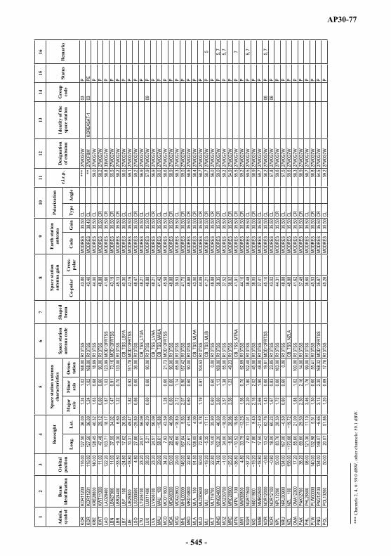
AP30-77
12
34
56
78
910
1112
1314
1516
Adm
in.
sym
bol
Bea
mid
entif
icat
ion
Orb
ital
posi
tion
Bor
esig
htSp
ace
stat
ion
ante
nna
char
acte
rist
ics
Spac
e st
atio
nan
tenn
a co
deSh
aped
beam
Spac
e st
atio
nan
tenn
a ga
inE
arth
stat
ion
ante
nna
Pola
riza
tion
e.i.r
.p.
Des
igna
tion
of e
mis
sion
Iden
tity
of th
e sp
ace
stat
ion
Gro
upco
deSt
atus
Rem
arks
Lon
g.L
at.
Maj
orax
isM
inor
axis
Ori
en-
tatio
nC
o-po
lar
Cro
ss-
pola
rC
ode
Gai
nT
ype
Ang
le
KOR
KOR1
1200
116.0
012
7.50
36.00
1.24
1.02
168.0
0R1
3TSS
43.80
MODR
ES
35.50
CL**
*27
M0G
7W
03P
KOR
KOR1
1201
116.0
012
7.50
36.00
1.24
1.02
168.0
0R1
3TSS
43.40
MODR
ES
38.43
CL**
27M
0F8W
KO
REAS
AT-1
03PE
KRE
KRE2
8600
140.0
012
8.45
40.32
1.63
0.68
18.89
R13T
SS
44
.00MO
DRES
35
.50CL
59.0
27M
0G7W
P
KWT
KWT1
1300
11.00
47.48
29.12
0.60
0.60
90.00
R13T
SS
48
.88MO
DRES
35
.50CR
58.2
27M
0G7W
P
LAO
LAO2
8400
122.2
010
3.71
18.17
1.87
1.03
123.9
9MO
D13F
RTSS
41
.60MO
DRES
35
.50CR
58.8
33M
0G7W
P
LBN
LBN2
7900
11.00
37.55
34.02
1.47
0.91
73.16
MOD1
3FRT
SS
43.19
MODR
ES
35.50
CR55
.527
M0G
7W
PLB
RLB
R244
006.6
01.2
20.7
013
3.00
R13T
SS
45
.13MO
DRES
35
.50CR
58.2
27M
0G7W
P
LBY
LBY_
_100
17.62
26.55
CB_T
SS_L
BYA
40.30
MODR
ES
35.50
CL58
.027
M0G
7W
PLIE
LIE25
300
10.31
49.47
1.82
0.92
151.7
8MO
D13F
RTSS
42
.19MO
DRES
35
.50CL
59.1
27M
0G7W
P
LSO
LSO3
0500
4.80
27.80
0.66
0.60
36.00
R13T
SS
48
.47MO
DRES
35
.50CR
59.2
27M
0G7W
P
LTU
LTU0
6100
23.20
24.51
56.09
CB_T
SS_L
TUA
48.21
MODR
ES
35.50
CL56
.927
M0G
7W
PLU
XLU
X114
0028
.205.2
149
.200.6
00.6
090
.00R1
3TSS
48.88
MODR
ES
35.50
CL57
.927
M0G
7W
09P
LVA
LVA0
6100
23.20
24.51
56.09
CB_T
SS_L
VAA
48.21
MODR
ES
35.50
CR56
.927
M0G
7W
PMA
UMA
U__1
0029
.0058
.61CB
_TSS
_MAU
A 41
.42MO
DRES
35
.50CL
59.0
27M
0G7W
P
MCO
MCO1
1600
34.20
7.93
43.59
1.28
0.60
21.73
MOD1
3FRT
SS
45.58
MODR
ES
35.50
CL58
.627
M0G
7W
PMD
AMD
A063
0050
.0028
.4546
.990.6
00.6
090
.00R1
3TSS
48.88
MODR
ES
35.50
CR58
.927
M0G
7W
PMD
GMD
G236
0029
.0046
.602.7
21.1
465
.00R1
3TSS
39.53
MODR
ES
35.50
CL58
.327
M0G
7W
PMH
LMH
L000
0014
6.00
167.6
49.8
32.0
70.9
015
7.42
R13T
SS
41
.75MO
DRES
35
.50CR
59.0
27M
0G7W
P
MKD
MKD1
4800
22.80
21.61
41.56
0.60
0.60
90.00
R13T
SS
48
.88MO
DRES
35
.50CR
58.9
27M
0G7W
P
MLA
MLA_
_100
91.50
108.0
54.0
0CB
_TSS
_MLA
A 43
.00MO
DRES
35
.50CR
58.4
27M
0G7W
P
MLD
MLD3
0600
50.00
72.95
5.78
1.19
0.91
104.5
3R1
3TSS
44.09
MODR
ES
35.50
CR58
.727
M0G
7W
PML
IML
I__10
017
.11CB
_TSS
_MLIB
41
.21MO
DRES
35
.50CR
58.7
27M
0G7W
P
5ML
TML
T147
0022
.8014
.4035
.900.6
00.6
00.0
0R1
3TSS
48.88
MODR
ES
35.50
CR56
.027
M0G
7W
PMN
GMN
G248
0074
.0010
2.20
46.60
3.60
1.13
169.0
0R1
3TSS
38.35
MODR
ES
35.50
CR59
.027
M0G
7W
P5,
7MO
ZMO
Z307
0034
.003.5
71.3
855
.00R1
3TSS
37.52
MODR
ES
35.50
CL59
.227
M0G
7W
P5,
7MR
CMR
C209
0028
.983.5
61.2
349
.23R1
3TSS
38.02
MODR
ES
35.50
CR54
.927
M0G
7W
PMT
NMT
N__1
0019
.66CB
_TSS
_MTN
A 41
.91MO
DRES
35
.50CR
55.5
27M
0G7W
P
7MW
IMW
I3080
04.8
033
.791.5
60.7
092
.69R1
3TSS
44.10
MODR
ES
35.50
CR59
.227
M0G
7W
PNG
RNG
R115
007.6
317
.012.2
01.8
010
2.40
R13T
SS
38
.48MO
DRES
35
.50CL
59.5
27M
0G7W
P
5, 7
NIG
NIG1
1900
7.80
9.40
2.16
2.02
45.00
R13T
SS
38
.05MO
DRES
35
.50CR
58.9
27M
0G7W
P
NMB
NMB0
2500
17.50
2.66
1.90
48.00
R13T
SS
37
.41MO
DRES
35
.50CL
59.7
27M
0G7W
P
NOR
NOR1
2000
13.42
62.76
1.43
0.60
19.61
MOD1
3FRT
SS
45.10
MODR
ES
35.50
CL56
.227
M0G
7W
06P
5, 7
NOR
NOR1
2100
18.00
60.23
1.67
0.83
23.85
R13T
SS
43
.02MO
DRES
35
.50CL
57.8
27M
0G7W
06
PNP
LNP
L122
0050
.0083
.7028
.301.7
20.6
016
3.00
R13T
SS
44
.31MO
DRES
35
.50CR
59.6
27M
0G7W
P
NRU
NRU3
0900
134.0
016
7.00
0.60
0.60
0.00
R13T
SS
48
.88MO
DRES
35
.50CL
57.5
27M
0G7W
P
NZL
NZL_
_100
158.0
0CB
_TSS
_NZL
A 48
.88MO
DRES
35
.50CL
59.6
27M
0G7W
P
OMA
OMA1
2300
17.20
55.60
21.00
1.88
1.02
100.0
0R1
3TSS
41.62
MODR
ES
35.50
CR58
.327
M0G
7W
PPA
KPA
K127
0038
.2069
.6029
.502.3
02.1
614
.00R1
3TSS
37.49
MODR
ES
35.50
CR58
.927
M0G
7W
PPH
LPH
L285
0098
.0012
1.30
11.10
3.46
1.76
99.00
R13T
SS
36
.60MO
DRES
35
.50CL
58.7
27M
0G7W
P
PLW
PLW
0000
014
0.00
132.9
85.5
11.3
00.6
055
.41R1
3TSS
45.53
MODR
ES
35.50
CR58
.827
M0G
7W
PPN
GPN
G131
0013
4.00
148.0
73.1
32.3
016
8.32
MOD1
3FRT
SS
35.87
MODR
ES
35.50
CR54
.527
M0G
7W
PPO
LPO
L132
0050
.0020
.0751
.861.2
00.6
917
.76R1
3TSS
45.26
MODR
ES
35.50
CL59
.227
M0G
7W
P
____
____
____
___
***
Cha
nnel
s 2, 4
, 6: 5
9.0
dBW
, oth
er c
hann
els:
59.
1dB
W.
- 545 -

AP30-78
12
34
56
78
910
1112
1314
1516
Adm
in.
sym
bol
Bea
mid
entif
icat
ion
Orb
ital
posi
tion
Bor
esig
htSp
ace
stat
ion
ante
nna
char
acte
rist
ics
Spac
e st
atio
nan
tenn
a co
deSh
aped
beam
Spac
e st
atio
nan
tenn
a ga
inE
arth
stat
ion
ante
nna
Pola
riza
tion
e.i.r
.p.
Des
igna
tion
of e
mis
sion
Iden
tity
of th
e sp
ace
stat
ion
Gro
upco
deSt
atus
Rem
arks
Lon
g.L
at.
Maj
orax
isM
inor
axis
Ori
en-
tatio
nC
o-po
lar
Cro
ss-
pola
rC
ode
Gai
nT
ype
Ang
le
POR
POR_
_100
37.65
CB_T
SS_P
ORA
47.17
MODR
ES
35.50
CR58
.427
M0G
7W
P5,
7PS
EYY
Y000
0034
.9931
.860.6
00.6
090
.00R1
3TSS
48.88
MODR
ES
35.50
CL58
.927
M0G
7W
P3
QAT
QAT2
4700
20.00
51.38
25.26
0.60
0.60
90.00
R13T
SS
48
.88MO
DRES
35
.50CL
54.5
27M
0G7W
P
ROU
ROU1
3600
50.00
25.12
45.75
1.17
0.73
9.52
R13T
SS
45
.15MO
DRES
35
.50CR
58.9
27M
0G7W
P
RRW
RRW
3100
011
.0030
.000.6
60.6
042
.00R1
3TSS
48.47
MODR
ES
35.50
CL59
.827
M0G
7W
PRU
SRS
TREA
1136
.0038
.0053
.002.2
02.2
00.0
0R1
3TSS
37.70
MODR
ES
35.50
CL53
.027
M0F
8W
RST-
105
PERU
SRS
TREA
1236
.0038
.0053
.002.2
02.2
00.0
0R1
3TSS
37.70
MODR
ES
35.50
CR53
.027
M0F
8W
RST-
105
PERU
SRS
TRED
1136
.0038
.0053
.002.2
02.2
00.0
0R1
3TSS
37.70
MODR
ES
35.50
CL53
.027
M0G
7W
RST-
105
PERU
SRS
TRED
1236
.0038
.0053
.002.2
02.2
00.0
0R1
3TSS
37.70
MODR
ES
35.50
CR53
.027
M0G
7W
RST-
105
PERU
SRS
TRSD
1136
.0038
.0053
.002.2
02.2
00.0
0R1
3TSS
37.70
MODR
ES
35.50
CL53
.027
M0G
7W
RST-
105
PRU
SRS
TRSD
1236
.0038
.0053
.002.2
02.2
00.0
0R1
3TSS
37.70
MODR
ES
35.50
CR53
.027
M0G
7W
RST-
105
PRU
SRS
TRSD
1336
.0038
.0053
.002.2
02.2
00.0
0R1
3TSS
37.70
MODR
ES
39.02
CL53
.027
M0G
7W
RST-
105
PRU
SRS
TRSD
1436
.0038
.0053
.002.2
02.2
00.0
0R1
3TSS
37.70
MODR
ES
39.02
CR53
.027
M0G
7W
RST-
105
PRU
SRS
TRSD
2156
.0065
.0063
.002.2
02.2
00.0
0R1
23FR
37.70
MODR
ES
35.50
CL55
.027
M0G
7W
RST-
214
PRU
SRS
TRSD
2256
.0065
.0063
.002.2
02.2
00.0
0R1
23FR
37.70
MODR
ES
35.50
CR55
.027
M0G
7W
RST-
214
PRU
SRS
TRSD
3186
.0097
.0062
.002.2
02.2
00.0
0R1
3TSS
37.70
MODR
ES
35.50
CL55
.027
M0G
7WRS
T-3
33P
RUS
RSTR
SD32
86.00
97.00
62.00
2.20
2.20
0.00
R13T
SS
37
.70MO
DRES
35
.50CR
55.0
27M
0G7W
RS
T-3
33P
RUS
RSTR
SD51
140.0
015
8.00
56.00
2.20
2.20
0.00
R13T
SS
37
.70MO
DRES
35
.50CL
55.0
27M
0G7W
RS
T-5
35P
RUS
RSTR
SD52
140.0
015
8.00
56.00
2.20
2.20
0.00
R13T
SS
37
.70MO
DRES
35
.50CR
55.0
27M
0G7W
RS
T-5
35P
RUS
RUS0
0401
110.0
012
8.73
54.30
4.25
2.02
156.8
1R1
3TSS
35.11
MODR
ES
35.50
CL58
.927
M0G
7W
RUS-
434
P5,
7, 8
RUS
RUS0
0402
110.0
012
8.73
54.30
4.25
2.02
156.8
1R1
3TSS
35.11
MODR
ES
35.50
CR58
.927
M0G
7W
RUS-
434
P5,
7, 8
S
S 13
800
5.00
16.20
61.00
1.04
0.98
14.00
R13T
SS
44
.36MO
DRES
35
.50CL
55.6
27M
0G7W
04
PS
S
1390
05.0
017
.0061
.502.0
01.0
010
.00R1
3TSS
41.44
MODR
ES
35.50
CL61
.127
M0G
7W
04P
SDN
SDN_
_100
30.24
13.53
CB_T
SS_S
DNA
40.26
MODR
ES
35.50
CR59
.427
M0G
7W
PSE
NSE
N222
0013
.801.4
61.0
413
9.00
R13T
SS
42.63
MODR
ES
35.50
CL58
.627
M0G
7W
P5,
7SE
YSE
Y000
0042
.5051
.862.4
31.0
427
.51R1
3TSS
40.44
MODR
ES
35.50
CR58
.927
M0G
7W
PSL
MSL
M000
0012
8.00
159.2
71.3
51.0
811
8.59
R13T
SS
42
.81MO
DRES
35
.50CL
58.9
27M
0G7W
P
SMO
SMO0
5700
0.60
0.60
90.00
R13T
SS
48
.88MO
DRES
35
.50CR
58.6
27M
0G7W
P
7SM
RSM
R311
0012
.6043
.700.6
00.6
00.0
0R1
3TSS
48.88
MODR
ES
35.50
CR57
.427
M0G
7W
P7
SNG
SNG1
5100
88.00
103.8
61.4
20.9
20.7
217
5.12
R13T
SS
46
.25MO
DRES
35
.50CL
58.5
27M
0G7W
P
SOM
SOM3
1200
37.80
45.16
7.11
3.31
1.51
65.48
R13T
SS
37
.46MO
DRES
35
.50CR
57.4
27M
0G7W
P
5SR
BSR
B148
0020
.5043
.980.9
10.6
014
5.16
R13T
SS
47
.07MO
DRES
35
.50CR
58.9
27M
0G7W
P
SRL
SRL2
5900
8.60
0.78
0.68
114.0
0R1
3TSS
47.20
MODR
ES
35.50
CR58
.427
M0G
7W
P6
STP
STP2
4100
6.17
1.45
0.65
0.60
153.5
1R1
3TSS
48.56
MODR
ES
35.50
CR56
.427
M0G
7W
PSU
ISU
I1400
010
.3149
.471.8
20.9
215
1.78
MOD1
3FRT
SS
42.19
MODR
ES
35.50
CL59
.127
M0G
7W
PSV
KSV
K144
0116
.7746
.781.7
10.8
914
9.15
MOD1
3FRT
SS
42.64
MODR
ES
35.50
CL59
.327
M0G
7W
PSV
KSV
K144
0216
.7746
.781.7
10.8
914
9.15
MOD1
3FRT
SS
42.64
MODR
ES
35.50
CR59
.327
M0G
7W
PSV
KSV
K144
0316
.7746
.781.7
10.8
914
9.15
MOD1
3FRT
SS
42.64
MODR
ES
35.50
CR59
.327
M0G
7W
37P
SVN
SVN1
4800
33.80
15.01
46.18
0.60
0.60
90.00
R13T
SS
48
.88MO
DRES
35
.50CR
58.9
27M
0G7W
P
SWZ
SWZ3
1300
4.80
31.39
0.60
0.60
90.00
R13T
SS
48
.88MO
DRES
35
.50CL
57.9
27M
0G7W
P
SYR
SYR2
2900
11.00
37.55
34.02
1.47
0.91
73.16
MOD1
3FRT
SS
43.19
MODR
ES
35.50
CL55
.527
M0G
7W
53P
SYR
SYR3
3900
11.00
37.60
34.20
1.32
0.88
74.00
MOD1
3FRT
SS
43.80
MODR
ES
35.50
CL56
.427
M0G
7W
53P
TCD
TCD1
4300
17.00
18.36
15.47
3.23
2.05
82.89
R13T
SS
36.23
MODR
ES
35.50
CR58
.927
M0G
7W
PTG
OTG
O226
000.7
28.6
11.1
20.6
010
9.54
R13T
SS
46
.19MO
DRES
35
.50CR
58.5
27M
0G7W
P
5, 7
- 546 -

AP30-79
12
34
56
78
910
1112
1314
1516
Adm
in.
sym
bol
Bea
mid
entif
icat
ion
Orb
ital
posi
tion
Bor
esig
htSp
ace
stat
ion
ante
nna
char
acte
rist
ics
Spac
e st
atio
nan
tenn
a co
deSh
aped
beam
Spac
e st
atio
nan
tenn
a ga
inE
arth
stat
ion
ante
nna
Pola
riza
tion
e.i.r
.p.
Des
igna
tion
of e
mis
sion
Iden
tity
of th
e sp
ace
stat
ion
Gro
upco
deSt
atus
Rem
arks
Lon
g.L
at.
Maj
orax
isM
inor
axis
Ori
en-
tatio
nC
o-po
lar
Cro
ss-
pola
rC
ode
Gai
nT
ype
Ang
le
THA
THA1
4200
98.00
100.7
512
.882.8
01.8
293
.77R1
3TSS
37.37
MODR
ES
35.50
CL58
.627
M0G
7W
PTJ
KTJ
K069
0038
.0071
.1438
.411.2
10.7
315
5.31
R13T
SS
45
.00MO
DRES
35
.50CL
58.8
27M
0G7W
P
5TK
MTK
M068
0050
.0059
.2438
.832.2
61.0
216
6.64
R13T
SS
40
.81MO
DRES
35
.50CR
58.9
27M
0G7W
P
5TL
STL
S000
0012
8.00
126.0
30.6
60.6
013
.92R1
3TSS
48.50
MODR
ES
35.50
CR58
.927
M0G
7W
PTO
NTO
N215
0017
0.75
1.59
0.60
71.33
R13T
SS
44
.64MO
DRES
35
.50CR
58.3
27M
0G7W
P
5TU
NTU
N150
009.5
033
.501.8
80.7
213
5.00
MOD1
3FRT
SS
43.13
MODR
ES
35.50
CR57
.327
M0G
7W
55P
TUN
TUN2
7200
2.10
31.75
3.41
1.81
179.1
8MO
D13F
RTSS
36
.54MO
DRES
35
.50CR
55.5
27M
0G7W
55
P4
TUR
TUR1
4500
42.00
34.95
39.09
3.18
0.99
0.79
R13T
SS
39
.47MO
DRES
35
.50CL
58.8
27M
0G7W
36
PTU
VTU
V000
0017
6.00
177.6
10.9
40.6
013
7.58
R13T
SS
46
.93MO
DRES
35
.50CR
58.9
27M
0G7W
P
TZA
TZA2
2500
11.00
34.60
2.41
1.72
129.0
0R1
3TSS
38.27
MODR
ES
35.50
CR58
.727
M0G
7W
PUA
EUA
E274
0052
.5053
.8524
.341.1
90.8
53.7
2R1
3TSS
44.39
MODR
ES
35.50
CR58
.227
M0G
7W
PUG
AUG
A051
0017
.0032
.201.0
41.5
01.0
268
.73R1
3TSS
42.62
MODR
ES
35.50
CL58
.227
M0G
7W
PUK
RUK
R063
0038
.2031
.7448
.222.2
90.9
617
7.78
R13T
SS
41
.01MO
DRES
35
.50CR
58.9
27M
0G7W
P
USA
GUM3
3100
122.0
014
4.50
13.10
0.60
0.60
0.00
R13T
SS
48
.88MO
DRES
35
.50CL
58.3
27M
0G7W
P
USA
MRA3
3200
121.8
014
5.90
16.90
1.20
0.60
76.00
R13T
SS
45
.87MO
DRES
35
.50CR
58.5
27M
0G7W
P
USA
PLM3
3200
170.0
07.0
00.6
00.6
00.0
0R1
3TSS
48.88
MODR
ES
35.50
CL57
.427
M0G
7W
PUS
AUS
AA_1
0017
0.00
CB_T
SS_U
SAA
48.88
MODR
ES
35.50
CL56
.127
M0G
7W
PUS
AW
AK33
400
140.0
016
6.50
19.20
0.60
0.60
0.00
R13T
SS
48
.88MO
DRES
35
.50CR
58.6
27M
0G7W
P
UZB
UZB0
7100
33.80
63.80
41.21
2.56
0.89
159.9
1R1
3TSS
40.84
MODR
ES
35.50
CR58
.827
M0G
7W
PVT
NVT
N325
0010
7.00
106.8
414
.213.4
31.7
610
9.43
R13T
SS
36
.65MO
DRES
35
.50CR
58.4
27M
0G7W
P
VUT
VUT1
2800
140.0
016
8.00
1.52
0.68
87.00
R13T
SS
44
.30MO
DRES
35
.50CL
57.8
27M
0G7W
P
YEM
YEM_
_100
11.00
48.05
14.64
CB_T
SS_Y
EMA
47.63
MODR
ES
35.50
CL54
.927
M0G
7W
PZM
BZM
B314
0027
.502.3
81.4
839
.00R1
3TSS
38.98
MODR
ES
35.50
CR58
.727
M0G
7W
PZW
EZW
E135
0029
.601.4
61.3
637
.00R1
3TSS
41.47
MODR
ES
35.50
CR59
.227
M0G
7W
P5,
7
- 547 -
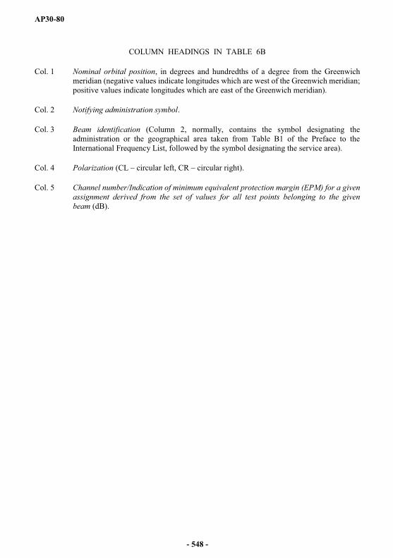
AP30-80
COLUMN HEADINGS IN TABLE 6B
Col. 1 Nominal orbital position, in degrees and hundredths of a degree from the Greenwich meridian (negative values indicate longitudes which are west of the Greenwich meridian; positive values indicate longitudes which are east of the Greenwich meridian).
Col. 2 Notifying administration symbol.
Col. 3 Beam identification (Column 2, normally, contains the symbol designating the administration or the geographical area taken from Table B1 of the Preface to the International Frequency List, followed by the symbol designating the service area).
Col. 4 Polarization (CL circular left, CR circular right).
Col. 5 Channel number/Indication of minimum equivalent protection margin (EPM) for a given assignment derived from the set of values for all test points belonging to the given beam (dB).
- 548 -

AP30-81
TAB
LE 6
B
Min
imum
equ
ival
ent p
rote
ctio
n m
argi
n of
ass
ignm
ents
in th
e R
egio
ns 1
and
3 P
lan
(sor
ted
by o
rbita
l pos
ition
)
12
34
5
Orb
ital
Posi
tion
Adm
in.
sym
bol
Bea
mId
entif
ica-
tion
Pola
r-iz
atio
nty
pe
Cha
nnel
num
ber
12
34
56
78
910
1112
1314
1516
1718
1920
2122
2324
2526
2728
2930
3132
3334
3536
3738
3940
Min
imum
EPM
178.0
0FJ
IFJ
I1930
0CR
6.16.1
6.16.1
6.16.1
6.16.1
6.16.1
6.16.1
178.0
0SM
OSM
O057
00CR
1.61.6
1.61.6
1.61.6
1.61.6
1.61.6
1.61.6
160.0
0F
OC
E101
00CL
99.9
99.9
99.9
99.9
99.9
99.9
99.9
99.9
99.9
99.9
99.9
99.9
37.20
GMB
GMB3
0200
CL4.6
1.91.9
1.91.9
1.91.9
1.91.9
1.9
37.20
IRL
IRL2
1100
CL2.6
0.60.6
0.60.6
0.60.6
0.60.6
0.6
37.20
NGR
NGR1
1500
CL6.8
6.86.8
6.86.8
6.86.8
6.86.8
6.9
37.00
AND
AND3
4100
CL0.3
0.30.3
0.30.3
0.30.3
0.30.3
0.8
37.00
GUI
GUI19
200
CR0.9
0.90.9
0.90.9
0.90.9
0.90.9
1.5
37.00
POR
POR_
_100
CR2.4
1.11.1
1.11.1
1.11.1
1.11.1
1.1
37.00
SEN
SEN2
2200
CL0.3
4.74.7
4.74.7
4.74.7
4.74.7
4.7
36.80
MTN
MTN_
_100
CR1.1
1.11.1
1.11.1
1.11.1
1.11.1
3.9
36.80
SMR
SMR3
1100
CR4.4
3.23.2
3.13.1
3.13.2
3.23.2
3.2
33.50
CPV
CPV3
0100
CL9.5
9.59.5
9.59.5
9.59.5
9.59.5
8.8
33.50
DNK
DNK0
90XR
CR0.9
0.9
33.50
DNK
DNK0
91XR
CR0.9
0.9
33.50
G
G 02
700
CR0.1
0.10.1
0.10.1
0.10.2
0.10.1
0.3
33.50
ISL
ISL0
4900
CL8.8
7.27.2
10.1
14.8
3.614
.83.6
21.7
21.7
33.50
ISL
ISL0
5000
CR0.1
0.10.1
33.50
LBR
LBR2
4400
CR3.3
0.40.4
0.40.4
0.40.4
0.40.4
0.4
33.50
SRL
SRL2
5900
CR0.4
1.01.0
1.01.0
0.91.0
0.91.0
1.0
30.00
BFA
BFA1
0700
CL1.5
1.51.5
1.51.5
1.51.5
1.51.5
2.4
30.00
EE_
___1
00CL
8.35.9
5.95.9
5.95.9
5.65.9
5.65.9
30.00
EHI
SP33
D1CL
0.40.4
0.40.4
0.4
30.00
EHI
SP33
D2CL
1.01.0
1.01.0
1.0
30.00
EHI
SPA2
7DCL
1.31.3
1.31.3
1.3
30.00
EHI
SPAS
A4CL
1.31.3
1.31.3
1.3
30.00
GNB
GNB3
0400
CL0.0
0.00.0
0.00.0
0.00.0
0.00.0
0.7
30.00
TGO
TGO2
2600
CR7.9
7.57.5
7.57.5
7.57.5
7.57.5
7.5
25.20
DNK
DNK_
_100
CL0.9
1.51.5
1.51.5
1.51.5
1.51.5
1.5
25.20
MRC
MRC2
0900
CR0.1
0.40.4
0.40.4
0.40.3
0.30.4
0.4
25.20
TUN
TUN1
5000
CR1.0
0.80.8
0.80.8
0.80.8
0.80.8
0.8
25.20
TUN
TUN2
7200
CR0.9
0.9
25.00
GHA
GHA1
0800
CR7.1
5.25.2
5.25.2
5.24.7
5.24.7
5.2
24.80
AGL
AGL2
9500
CL4.6
3.63.6
3.63.6
3.63.6
3.63.6
3.6
- 549 -
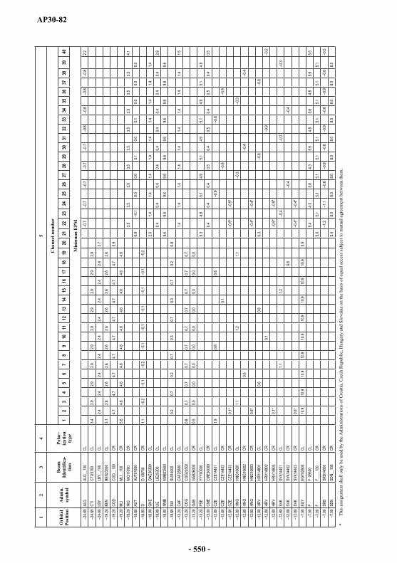
AP30-82
12
34
5
Orb
ital
Posi
tion
Adm
in.
sym
bol
Bea
mId
entif
ica-
tion
Pola
r-iz
atio
nty
pe
Cha
nnel
num
ber
12
34
56
78
910
1112
1314
1516
1718
1920
2122
2324
2526
2728
2930
3132
3334
3536
3738
3940
Min
imum
EPM
24.80
ALG
ALG_
_100
CL0.7
0.70.7
0.70.7
0.80.8
0.80.8
2.2
24.80
CTI
CTI23
700
CL3.4
2.92.9
2.92.9
2.92.9
2.92.9
2.9
24.80
LBY
LBY_
_100
CL2.4
2.42.4
2.42.4
2.42.4
2.42.4
2.7
19.20
BEN
BEN2
3300
CL3.1
2.62.6
2.62.6
2.62.6
2.62.6
2.6
19.20
COD
COD_
_100
CR4.7
4.74.7
4.74.7
4.74.7
4.74.7
5.9
19.20
MLI
MLI__
100
CR5.6
4.64.6
4.64.6
4.64.6
4.64.6
4.6
19.20
NIG
NIG1
1900
CR3.5
3.53.5
3.53.5
3.53.5
3.53.5
4.1
18.80
AUT
AUT0
1600
CR0.9
0.10.0
0.00.1
0.00.1
0.00.0
0.0
18.80
D
D 08
700
CR1.1
0.20.1
0.20.1
0.10.1
0.10.1
0.2
18.80
GNE
GNE3
0300
CL2.0
1.41.4
1.41.4
1.41.4
1.41.4
1.4
18.80
LIELIE
2530
0CL
0.40.4
0.40.4
0.40.4
0.40.4
0.42.8
18.80
NMB
NMB0
2500
CL8.6
9.69.6
9.69.6
9.69.6
9.69.6
9.6
18.80
SUI
SUI14
000
CL0.2
0.70.2
0.70.3
0.70.3
0.70.2
0.8
13.20
CAF
CAF2
5800
CL1.4
1.41.4
1.41.4
1.41.4
1.41.4
1.5
13.20
COG
COG2
3500
CL0.8
0.70.7
0.70.7
0.70.7
0.70.7
0.7
13.20
GAB
GAB2
6000
CR0.5
0.00.0
0.00.0
0.00.0
0.00.0
0.0
13.20
PSE
YYY0
0000
CL5.3
4.85.1
4.95.1
4.95.1
4.95.1
4.9
13.00
CME
CME3
0000
CR0.4
0.40.4
0.50.4
0.50.4
0.50.4
0.5
12.80
CZE
CZE1
4401
CL1.9
0.80.6
0.90.8
12.80
CZE
CZE1
4402
CR0.1
0.90.9
12.80
CZE
CZE1
4403
CR0.1
*0.9
*0.9
*
12.80
HNG
HNG1
0601
CL1.1
1.21.1
0.30.3
12.80
HNG
HNG1
0602
CR0.6
0.40.4
12.80
HNG
HNG1
0603
CR0.6
*0.4
*0.4
*
12.80
HRV
HRV1
4801
CL0.6
0.80.3
0.80.8
12.80
HRV
HRV1
4802
CR0.1
0.90.2
12.80
HRV
HRV1
4803
CR0.1
*0.9
*0.9
*
12.80
SVK
SVK1
4401
CL1.1
1.20.4
0.30.3
12.80
SVK
SVK1
4402
CR0.6
0.40.4
12.80
SVK
SVK1
4403
CR0.6
*0.4
*0.4
*
7.00
EGY
EGY0
2600
CL10
.910
.910
.910
.910
.910
.910
.910
.910
.95.9
7.00
F
F 09
300
CL5.4
4.35.6
4.35.6
4.85.6
4.85.6
5.5
7.00
F
F___
_100
CR5.0
5.15.1
5.15.1
5.15.1
5.15.1
5.1
7.00
SRB
SRB1
4800
CR1.2
1.10.6
0.90.6
0.90.6
0.90.6
0.5
7.00
SDN
SDN_
_100
CR5.4
8.08.0
8.08.0
8.08.0
8.08.0
8.0
*Th
is as
sign
men
t sha
ll on
ly b
e us
ed b
y th
e A
dmin
istra
tions
of C
roat
ia, C
zech
Rep
ublic
, Hun
gary
and
Slo
vaki
a on
the
basis
of e
qual
acc
ess s
ubje
ct to
mut
ual a
gree
men
t bet
wee
n th
em.
- 550 -
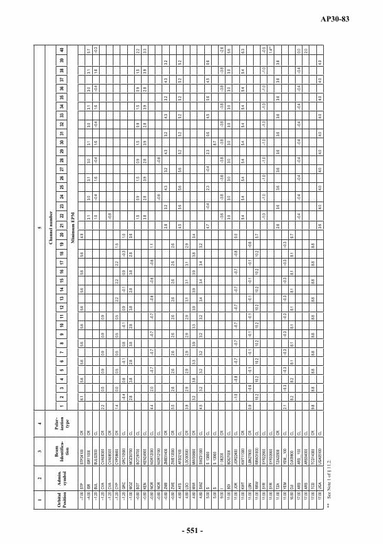
AP30-83
12
34
5
Orb
ital
Posi
tion
Adm
in.
sym
bol
Bea
mId
entif
ica-
tion
Pola
r-iz
atio
nty
pe
Cha
nnel
num
ber
12
34
56
78
910
1112
1314
1516
1718
1920
2122
2324
2526
2728
2930
3132
3334
3536
3738
3940
Min
imum
EPM
7.00
STP
STP2
4100
CR6.1
5.65.6
5.65.6
5.65.6
5.65.6
4.9
4.00
ISR
ISR1
1000
CR3.1
3.03.1
3.03.1
3.03.1
3.03.1
5.7
1.20
BUL
BUL0
2000
CL1.0
0.41.6
0.41.6
0.41.6
0.41.6
0.3
1.20
CVA
CVA0
8300
CR2.2
0.50.9
0.90.9
0.9
1.20
CVA
CVA0
8500
CR0.8
1.20
CYP
CYP0
8600
CR1.4
0.00.5
0.50.5
0.52.2
2.22.2
1.5
1.20
GRC
GRC1
0500
CL0.4
0.60.1
0.80.1
0.90.1
0.90.3
1.0
1.00
MOZ
MOZ3
0700
CL2.8
3.82.8
3.82.8
3.82.8
3.82.8
3.6
0.80
BOT
BOT2
9700
CL1.5
0.91.5
0.91.5
0.91.5
0.91.5
2.2
0.80
KEN
KEN2
4900
CL3.8
2.83.9
2.83.9
2.83.9
2.83.9
3.3
0.80
NOR
NOR1
2000
CL4.4
2.00.7
0.70.7
0.70.6
0.60.6
1.1
0.80
NOR
NOR1
2100
CL0.6
0.6
0.80
ZMB
ZMB3
1400
CR2.8
3.24.3
3.24.3
3.24.3
3.24.3
3.2
0.80
ZWE
ZWE1
3500
CR5.5
2.62.6
2.62.6
2.62.6
2.62.6
2.6
4.80
AFS
AFS0
2100
CL4.5
5.65.6
5.65.2
5.25.2
5.25.2
5.2
4.80
LSO
LSO3
0500
CR3.9
2.92.9
2.92.9
2.93.1
3.13.1
2.9
4.80
MWI
MWI30
800
CR3.2
3.83.3
3.93.3
3.93.9
3.93.8
3.4
4.80
SWZ
SWZ3
1300
CL4.5
3.23.2
3.23.2
3.23.4
3.43.4
3.2
5.00
SS
1380
0CL
4.70.4
2.30.4
2.30.6
4.50.6
4.50.6
5.00
SS
1390
0CL
8.7
9.00
II 0
8200
CR3.6
3.83.6
3.83.8
3.83.8
3.83.8
2.6
11.00
BDI
BDI27
000
CL3.0
3.03.0
3.03.0
3.03.0
3.03.0
5.6
11.00
JOR
JOR2
2400
CL1.0
0.80.7
0.70.7
0.70.7
0.70.8
0.0
11.00
KWT
KWT1
1300
CR5.4
5.45.4
5.45.4
5.45.4
5.45.4
6.3
11.00
LBN
LBN2
7900
CR0.9
0.60.1
0.10.1
0.10.1
0.10.1
0.6
11.00
RRW
RRW
3100
0CL
10.2
10.2
10.2
10.2
10.2
10.2
10.2
10.2
10.2
5.7
11.00
SYR
SYR2
2900
CL1.0
1.01.0
1.01.0
1.01.0
1.01.0
0.5
11.00
SYR
SYR3
3900
CL1.4
**
11.00
TZA
TZA2
2500
CR2.6
3.63.6
3.63.6
3.63.6
3.63.6
3.6
11.00
YEM
YEM_
_100
CL2.1
0.30.3
0.30.3
0.30.3
0.30.3
0.3
16.80
DJI
DJI09
900
CL8.2
8.28.1
8.18.1
8.18.1
8.18.1
6.7
17.00
ARS
ARS_
_100
CL0.4
0.40.4
0.40.4
0.40.4
0.40.4
0.0
17.00
ARS
ARS3
4000
CL2.0
17.00
TCD
TCD1
4300
CR9.8
8.88.8
8.88.8
8.88.8
8.88.8
8.8
17.00
UGA
UGA0
5100
CL3.6
4.04.0
4.04.0
4.04.0
4.04.0
4.0
**Se
e N
ote
1 of
§11
.2.
- 551 -

AP30-84
12
34
5
Orb
ital
Posi
tion
Adm
in.
sym
bol
Bea
mId
entif
ica-
tion
Pola
r-iz
atio
nty
pe
Cha
nnel
num
ber
12
34
56
78
910
1112
1314
1516
1718
1920
2122
2324
2526
2728
2930
3132
3334
3536
3738
3940
Min
imum
EPM
17.20
OMA
OMA1
2300
CR1.7
1.71.7
1.71.7
1.71.7
1.71.7
0.9
20.00
QAT
QAT2
4700
CL5.9
5.95.9
5.95.9
5.95.9
5.85.8
6.2**
22.80
ARM
ARM0
6400
CR0.5
0.50.5
0.50.5
0.50.5
0.40.5
2.7
22.80
ERI
ERI09
200
CR2.3
2.82.8
2.82.8
2.82.8
2.82.8
2.8
22.80
FIN
FIN1
0300
CL0.5
1.21.9
2.01.8
2.11.7
2.21.6
4.9
22.80
FIN
FIN1
0400
CL0.4
1.1
22.80
MKD
MKD1
4800
CR3.6
3.33.3
3.33.3
3.33.3
3.23.3
3.3
22.80
MLT
MLT1
4700
CR1.7
1.81.7
1.81.7
1.81.7
1.71.8
3.4
23.20
AZE
AZE0
6400
CL0.6
0.10.1
0.10.1
0.10.1
0.10.1
0.1
23.20
GEO
GEO0
6400
CR5.3
4.14.1
4.14.1
4.14.1
4.14.1
4.1
23.20
LTU
LTU0
6100
CL1.4
0.10.0
0.00.1
0.10.1
0.20.2
0.2
23.20
LVA
LVA0
6100
CR0.8
0.80.8
0.80.9
0.90.9
0.90.9
0.3
28.20
LUX
LUX1
1400
CL3.1
2.92.8
2.82.8
2.82.8
2.82.8
2.8
29.00
COM
COM2
0700
CR11
.29.5
9.59.5
9.59.5
9.59.5
9.59.6
29.00
MAU
MAU_
_100
CL11
.011
.011
.011
.011
.011
.011
.011
.111
.112
.7
29.00
MDG
MDG2
3600
CL14
.013
.613
.513
.413
.413
.313
.313
.213
.213
.2
33.80
SVN
SVN1
4800
CR0.5
0.50.5
0.50.5
0.50.5
0.50.4
1.6
33.80
UZB
UZB0
7100
CR3.3
1.91.9
1.91.9
1.91.9
1.91.9
1.9
34.00
BHR
BHR2
5500
CR0.9
0.98.7
8.89.2
8.89.2
8.89.2
8.8
34.00
IRN
IRN1
0900
CL1.2
0.90.9
0.90.9
0.90.9
0.90.9
0.98.8
8.5
34.20
MCO
MCO1
1600
CL0.7
1.01.0
1.01.0
1.01.0
1.01.0
1.0
36.00
ETH
ETH0
9200
CL11
.811
.811
.811
.811
.811
.811
.811
.811
.812
.1
36.00
RUS
RSTR
EA11
CL3.6
3.63.6
3.6
36.00
RUS
RSTR
EA12
CR4.3
4.34.3
4.2
36.00
RUS
RSTR
ED11
CL3.6
3.63.6
3.6
36.00
RUS
RSTR
ED12
CR4.3
4.34.3
4.2
36.00
RUS
RSTR
SD11
CL4.5
4.94.9
4.94.9
4.94.9
4.9
36.00
RUS
RSTR
SD12
CR3.4
3.43.4
3.43.4
3.43.4
3.4
36.00
RUS
RSTR
SD13
CL4.9
5.05.0
5.05.0
5.05.0
5.0
36.00
RUS
RSTR
SD14
CR3.5
3.53.5
3.53.5
3.53.5
3.6
37.80
BLR
BLR0
6200
CL3.8
1.31.3
1.31.3
1.31.3
1.31.3
1.3
37.80
SOM
SOM3
1200
CR3.3
3.311
.710
.211
.710
.211
.710
.211
.710
.4
38.00
TJK
TJK0
6900
CL0.6
1.27.9
7.87.9
7.87.9
7.87.9
7.9
38.20
BEL
BEL0
1800
CL2.5
2.22.0
1.72.0
1.72.0
1.72.0
3.4
38.20
HOL
HOL2
1300
CL1.6
1.61.6
1.61.6
1.61.6
1.61.6
2.5
38.20
PAK
PAK1
2700
CR3.5
3.53.5
3.53.5
3.53.5
3.53.5
4.62.0
2.1
**Se
e N
ote
1 of
§11
.2.
- 552 -

AP30-85
12
34
5
Orb
ital
Posi
tion
Adm
in.
sym
bol
Bea
mId
entif
ica-
tion
Pola
r-iz
atio
nty
pe
Cha
nnel
num
ber
12
34
56
78
910
1112
1314
1516
1718
1920
2122
2324
2526
2728
2930
3132
3334
3536
3738
3940
Min
imum
EPM
38.20
UKR
UKR0
6300
CR0.6
0.60.6
0.60.6
0.60.6
0.60.6
1.5
42.00
TUR
TUR1
4500
CL1.7
1.71.7
1.71.7
1.71.7
1.71.7
1.7
42.50
SEY
SEY0
0000
CR12
.313
.013
.113
.113
.113
.113
.113
.113
.114
.4
44.50
EST
EST0
6100
CR6.6
5.65.6
5.65.6
5.65.6
5.65.6
5.6
50.00
AFG
AFG_
_100
CL0.3
0.50.5
0.50.5
0.50.5
0.50.5
0.53.0
2.2
50.00
CLN
CLN2
1900
CL0.8
0.50.5
0.50.5
0.50.5
0.50.5
0.51.5
1.6
50.00
IRQ
IRQ2
5600
CL4.2
3.63.6
3.63.6
3.63.6
3.63.6
3.6**
50.00
KGZ
KGZ0
7000
CR0.5
0.50.5
0.50.5
0.50.5
0.50.5
1.0
50.00
MDA
MDA0
6300
CR0.7
0.71.4
1.41.4
1.41.4
1.41.4
1.4
50.00
MLD
MLD3
0600
CR6.3
4.84.8
4.84.8
4.84.8
4.84.8
4.84.7
4.3
50.00
NPL
NPL1
2200
CR3.1
3.13.1
3.13.1
3.13.1
3.13.1
3.22.2
3.4
50.00
POL
POL1
3200
CL2.4
2.73.1
3.13.1
3.13.1
3.13.1
3.2
50.00
ROU
ROU1
3600
CR4.9
3.93.9
3.93.9
3.93.9
3.93.9
3.9
50.00
TKM
TKM0
6800
CR1.0
2.48.5
8.58.5
8.58.5
8.58.5
8.7
52.50
UAE
UAE2
7400
CR3.2
3.214
.315
.115
.115
.115
.115
.115
.115
.1**
55.80
IND
INDA
_100
CR2.6
2.62.6
2.62.6
2.62.6
2.62.6
3.23.9
6.4
55.80
IND
INDB
_100
CL2.7
2.12.1
2.12.1
2.12.1
2.12.1
2.13.2
3.2
56.00
BIH
BIH1
4800
CL5.9
5.95.9
5.95.9
5.95.9
5.95.9
5.9
56.00
RUS
RSTR
SD21
CL9.3
11.6
11.6
11.6
11.6
11.6
11.6
11.6
56.00
RUS
RSTR
SD22
CR3.5
3.53.5
3.53.5
3.53.5
3.6
56.40
KAZ
KAZ0
6600
CR3.6
1.31.3
1.31.3
1.31.3
1.31.3
1.3
62.00
ALB
ALB2
9600
CL8.6
10.9
33.5
33.5
33.5
33.5
33.5
33.5
33.5
34.4
62.00
CHN
CHN1
5500
CL2.7
1.51.5
1.51.5
1.51.5
1.51.5
1.51.5
1.5
62.00
CHN
CHNA
_100
CR1.9
1.91.9
1.91.9
1.91.9
1.91.9
2.12.3
5.3
68.00
IND
IND0
3700
CL4.5
4.54.5
4.54.5
4.54.5
4.54.5
4.54.5
7.2
68.00
IND
IND0
4700
CR5.4
5.05.0
5.05.0
5.05.0
5.05.0
5.05.0
5.0
68.00
IND
INDD
_100
CR6.0
4.64.6
4.64.6
4.64.6
4.64.6
4.64.6
4.6
74.00
BGD
BGD2
2000
CR12
.111
.011
.011
.011
.011
.011
.011
.011
.011
.04.1
4.1
74.00
BRU
BRU3
3000
CR5.1
5.15.1
5.15.1
5.15.1
5.15.1
4.84.5
6.9
74.00
MNG
MNG2
4800
CR6.6
6.626
.499
.999
.999
.999
.999
.999
.999
.9
80.20
INS
INSA
_100
CR12
.89.7
9.79.7
9.79.7
9.79.7
9.79.7
9.79.7
86.00
BTN
BTN0
3100
CR11
.88.9
8.98.9
8.98.9
8.98.9
8.98.9
8.98.9
86.00
CBG
CBG2
9900
CR9.7
9.79.7
9.79.7
9.79.7
9.79.7
9.79.7
11.7
86.00
RUS
RSTR
SD31
CL5.5
99.9
99.9
99.9
99.9
99.9
99.9
99.9
86.00
RUS
RSTR
SD32
CR99
.999
.999
.999
.999
.999
.999
.999
.9
88.00
SNG
SNG1
5100
CL2.3
1.31.3
1.31.3
1.31.3
1.31.3
1.31.3
1.3
**Se
e N
ote
1 of
§11
.2.
- 553 -
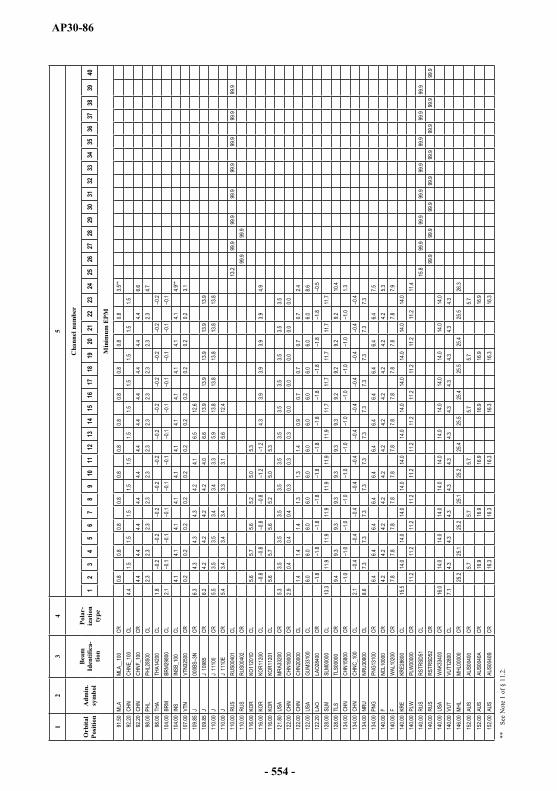
AP30-86
12
34
5
Orb
ital
Posi
tion
Adm
in.
sym
bol
Bea
mId
entif
ica-
tion
Pola
r-iz
atio
nty
pe
Cha
nnel
num
ber
12
34
56
78
910
1112
1314
1516
1718
1920
2122
2324
2526
2728
2930
3132
3334
3536
3738
3940
Min
imum
EPM
91.50
MLA
MLA_
_100
CR0.8
0.80.8
0.80.8
0.80.8
0.80.8
0.80.8
3.5**
92.20
CHN
CHNE
_100
CL4.4
1.51.5
1.51.5
1.51.5
1.51.5
1.51.5
1.592
.20CH
NCH
NF_1
00CR
4.44.4
4.44.4
4.44.4
4.44.4
4.44.4
4.46.6
98.00
PHL
PHL2
8500
CL2.3
2.32.3
2.32.3
2.32.3
2.32.3
2.32.3
4.798
.00TH
ATH
A142
00CL
1.80.2
0.20.2
0.20.2
0.20.2
0.20.2
0.20.2
104.0
0BR
MBR
M298
00CL
2.10.1
0.10.1
0.10.1
0.10.1
0.10.1
0.10.1
104.0
0IN
SIN
SB_1
00CL
4.14.1
4.14.1
4.14.1
4.14.1
4.14.1
4.14.9
**10
7.00
VTN
VTN3
2500
CR0.2
0.20.2
0.20.2
0.20.2
0.20.2
0.20.2
3.110
9.85
J 00
0BS
3NCR
6.34.3
4.34.3
4.24.1
6.512
.610
9.85
J J
1098
5CR
6.24.2
4.24.2
4.24.0
6.613
.913
.913
.913
.913
.911
0.00
J J
1110
0CR
5.53.5
3.53.4
3.43.3
5.913
.813
.813
.813
.813
.811
0.00
J J
1110
ECR
5.43.4
3.43.4
3.33.1
5.612
.411
0.00
RUS
RUS0
0401
CL13
.299
.999
.999
.999
.999
.999
.999
.911
0.00
RUS
RUS0
0402
CR99
.999
.911
6.00
KOR
KO11
201D
CL5.6
5.75.6
5.25.0
5.311
6.00
KOR
KOR1
1200
CL0.8
0.80.8
0.81.2
1.24.3
3.93.9
3.93.9
4.911
6.00
KOR
KOR1
1201
CL5.6
5.75.6
5.25.0
5.312
1.80
USA
MRA3
3200
CR5.3
3.53.5
3.53.5
3.53.5
3.53.5
3.53.5
3.512
2.00
CHN
CHN1
9000
CR2.9
0.40.4
0.40.3
0.30.3
0.00.0
0.00.0
0.012
2.00
CHN
CHN2
0000
CL1.4
1.41.4
1.31.3
1.40.9
0.70.7
0.70.7
2.412
2.00
USA
GUM3
3100
CL6.0
6.06.0
6.06.0
6.06.0
6.06.0
6.06.0
8.612
2.20
LAO
LAO2
8400
CR1.8
1.81.8
1.81.8
1.81.8
1.81.8
1.81.8
0.512
8.00
SLM
SLM0
0000
CL13
.311
.911
.911
.911
.911
.911
.911
.711
.711
.711
.711
.712
8.00
TLS
TLS0
0000
CR9.4
9.39.3
9.39.3
9.39.3
9.29.2
9.29.2
10.4
134.0
0CH
NCH
N158
00CR
1.01.0
1.01.0
1.01.0
1.01.0
1.01.0
1.01.3
134.0
0CH
NCH
NC_1
00CL
2.10.4
0.40.4
0.40.4
0.40.4
0.40.4
0.40.4
134.0
0NR
UNR
U309
00CL
8.67.3
7.37.3
7.37.3
7.37.3
7.37.3
7.37.3
134.0
0PN
GPN
G131
00CR
6.46.4
6.46.4
6.46.4
6.46.4
6.46.4
6.47.5
140.0
0F
NC
L100
00CR
4.24.2
4.24.2
4.24.2
4.24.2
4.24.2
4.25.3
140.0
0F
W
AL10
200
CR7.8
7.87.8
7.87.8
7.87.8
7.87.8
7.87.8
7.914
0.00
KRE
KRE2
8600
CL15
.514
.014
.014
.014
.014
.014
.014
.014
.014
.014
.014
.014
0.00
PLW
PLW
0000
0CR
11.2
11.2
11.2
11.2
11.2
11.2
11.2
11.2
11.2
11.2
11.2
11.4
140.0
0RU
SRS
TRSD
51CL
15.8
99.9
99.9
99.9
99.9
99.9
99.9
99.9
140.0
0RU
SRS
TRSD
52CR
99.9
99.9
99.9
99.9
99.9
99.9
99.9
99.9
140.0
0US
AW
AK33
400
CR16
.014
.014
.014
.014
.014
.014
.014
.014
.014
.014
.014
.014
0.00
VUT
VUT1
2800
CL7.1
4.34.3
4.34.3
4.34.3
4.34.3
4.34.3
4.314
6.00
MHL
MHL0
0000
CR25
.225
.125
.225
.125
.225
.425
.525
.425
.525
.425
.526
.3
152.0
0AU
SAU
S004
00CR
5.75.7
5.75.7
5.75.7
152.0
0AU
SAU
S004
0ACR
16.9
16.9
16.9
16.9
16.9
16.9
152.0
0AU
SAU
S004
0BCR
16.3
16.3
16.3
16.3
16.3
16.3
**Se
e N
ote
1 of
§11
.2.
- 554 -

AP30-87
12
34
5
Orb
ital
Posi
tion
Adm
in.
sym
bol
Bea
mId
entif
ica-
tion
Pola
r-iz
atio
nty
pe
Cha
nnel
num
ber
12
34
56
78
910
1112
1314
1516
1718
1920
2122
2324
2526
2728
2930
3132
3334
3536
3738
3940
Min
imum
EPM
152.0
0AU
SAU
S004
0CCR
17.4
17.4
17.4
17.4
17.4
17.4
152.0
0AU
SAU
S005
00CL
5.15.1
9.19.1
9.19.1
152.0
0AU
SAU
S006
00CL
4.34.3
4.38.7
8.78.7
152.0
0AU
SAU
SA_1
00CR
9.27.5
7.5
158.0
0FS
MFS
M000
00CR
14.9
23.5
14.6
23.5
14.6
23.5
23.8
24.9
25.3
24.9
25.3
24.9
158.0
0NZ
LNZ
L__1
00CL
12.1
8.512
.18.5
12.1
8.612
.112
.112
.112
.112
.115
.1
164.0
0AU
SAU
S007
00CR
4.84.8
4.89.4
9.49.4
164.0
0AU
SAU
S007
0ACR
7.77.7
7.715
.815
.815
.8
164.0
0AU
SAU
S008
00CL
5.45.4
5.45.4
5.45.4
164.0
0AU
SAU
S009
00CR
7.83.6
3.63.6
7.27.2
164.0
0AU
SAU
S009
0ACR
13.0
7.17.1
7.113
.013
.0
164.0
0AU
SAU
S009
0BCR
16.2
7.77.7
7.715
.715
.7
164.0
0AU
SAU
SB_1
00CL
4.64.6
4.6
170.0
0US
APL
M332
00CL
6.56.5
6.56.5
6.56.5
6.56.5
6.56.5
6.59.2
170.0
0US
AUS
AA_1
00CL
9.97.4
7.47.4
7.47.4
7.47.4
7.47.4
7.47.4
170.7
5TO
NTO
N215
00CR
9.69.6
9.69.6
9.69.6
9.69.7
9.79.7
9.711
.6
176.0
0KI
RKI
R__1
00CL
13.4
10.5
10.5
10.5
10.5
10.5
10.5
10.5
10.5
10.5
10.5
10.5
176.0
0TU
VTU
V000
00CR
6.26.2
6.26.2
6.26.2
6.26.2
6.26.2
6.29.1
11.3
(SU
P- W
RC
-03)
- 555 -
AP30-88
ARTICLE 12
Relationship to Resolution 507 (REV.WRC-03)*
12.1 The provisions and associated Plans for the broadcasting-satellite service in Regions 1 and 3 and in Region 2, of this Appendix, shall be regarded as including a world agreement and associated Plans for Regions 1, 2 and 3 in accordance with resolves 1 of Resolution 507(Rev.WRC-03)*, which requires the stations in the broadcasting-satellite service to be established and operated in accordance with such agreements and associated Plans.
ARTICLE 13
Interference
13.1 The Member States of the Union shall endeavour to agree on the action required to reduce harmful interference which might be caused by the application of these provisions and the associated Plans.
ARTICLE 14
Period of validity of the provisions and associated Plans
14.1 For Regions 1 and 3, the provisions and associated Plan have been prepared in order to meet the requirements of the broadcasting-satellite service in the bands concerned for a period of at least fifteen years from 1 January 1979.
14.2 For Region 2, the provisions and associated Plan have been prepared in order to meet the requirements of the broadcasting-satellite service in the bands concerned for a period extending until at least 1 January 1994.
14.3 In any event, the provisions and associated Plans shall remain in force until their revision by a competent radiocommunication conference convened in accordance with the relevant provisions of the Constitution and Convention in force.
_______________* Note by the Secretariat: This Resolution was revised by WRC-12 and WRC-15.
- 556 -
AP30-89
ANNEX 1 (REV.WRC-15)
Limits for determining whether a service of an administration is affected by a proposed modification to the Region 2 Plan or by a proposed
new or modified assignment in the Regions 1 and 3 List or when it is necessary under this Appendix to seek
the agreement of any other administration25
(See Article 4)
1 Limits for the interference into frequency assignments in conformity with the Regions 1 and 3 Plan or with the Regions 1 and 3 List or into new or modified assignments in the Regions 1 and 3 List
Under assumed free-space propagation conditions, the power flux-density of a proposed new or dB(W/(m2 · 27 MHz)).
With respect to § 4.1.1 a) or b) of Article 4, an administration in Region 1 or 3 is considered by the Bureau as being affected if the minimum orbital spacing between the wanted and interfering space stations, under worst-case station-keeping conditions, is less than 9°.
However, an administration in Region 1 or 3 is considered as not being affected if either of the following two conditions is met:
a) under assumed free-space propagation conditions, the power flux-density at any test point within the service area associated with any of its frequency assignments in the Plan or in the List or for which the procedure of Article 4 has been initiated, does not exceed the following values:26 (WRC-15)
dB(W/(m2 27 MHz)) for 0° < 0.23°
dB(W/(m2 27 MHz)) for 0.23° < °
2 dB(W/(m2 27 MHz)) for 2.0° < °
dB(W/(m2 27 MHz)) for 3.59° < °
where is the minimum geocentric orbital separation in degrees between the wanted and interfering space stations, taking into account the respective East-West station-keeping accuracies;
_______________25 With respect to this Annex, except for Section 2, the limits relate to the power flux-density which would be obtained assuming free-space propagation conditions.
With respect to Section 2 of this Annex, the limit specified relates to the overall equivalent protection margin calculated in accordance with § 2.2.4 of Annex 5.
26 (SUP - WRC-15)
- 557 -
AP30-90
b) the effect of the proposed new or modified assignments in the List is that the equivalent downlink protection margin27 corresponding to a test point of its assignment in theRegions 1 and 3 Plan or List, or for which the procedure of Article 4 has been initiated, including cumulative effect of any previous modification to the List or any previous agreement, does not fall more than 0.45 dB below 0 dB or, if already negative, more than 0.45 dB below the value resulting from:
the Regions 1 and 3 Plan and List as established by WRC-2000; or
a proposed new or modified assignment to the List in accordance with this Appendix; or
a new entry in the Regions 1 and 3 List as a result of successful application of Article 4 procedures.
NOTE In performing the calculation, the effect at the receiver input of all the co-channel and adjacent-channel signals is expressed in terms of one equivalent co-channel interfering signal. This value is usually expressed in decibels. (WRC-03)
2 Limits to the change in the overall equivalent protection margin for frequency assignments in conformity with the Region 2 Plan
With respect to § 4.2.3 c) of Article 4, an administration in Region 2 is considered as being affected if the overall equivalent protection margin28 corresponding to a test point of its entry in the Region 2Plan, including the cumulative effect of any previous modification to that Plan or any previous agreement, falls more than 0.25 dB below 0 dB, or, if already negative, more than 0.25 dB below the value resulting from:
the Region 2 Plan as established by the 1983 Conference; or
a modification of the assignment in accordance with this Appendix; or
a new entry in the Region 2 Plan under Article 4; or
any agreement reached in accordance with this Appendix. (WRC-03)
3 Limits to the change in the power flux-density to protect the broadcasting-satellite service in Regions 1 and 2 in the band 12.2-12.5 GHz and in Region 3 in the band 12.5-12.7 GHz
With respect to § 4.1.1 c) of Article 4, an administration in Region 2 is considered as being affected if the proposed new or modified assignment in the Regions 1 and 3 List would result in exceeding the following power flux-density values, at any test point in the service area of its overlapping frequency assignments:
_______________27 For the definition of the equivalent protection margin, see § 3.4 of Annex 5.
28 For the definition of the overall equivalent protection margin, see § 1.11 of Annex 5.
- 558 -
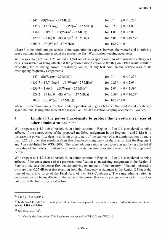
AP30-91
dB(W/(m2 27 MHz)) for 0° < 0.23°
+ 17.74 log dB(W/(m2 27 MHz)) for 0.23° < 1.8°
+ 0.89 2 dB(W/(m2 27 MHz)) for 1.8° < 5.0°
+ 25 log dB(W/(m2 27 MHz)) for 5.0° < 10.57°
3.6 dB(W/(m2 27 MHz)) for 10.57°
where is the minimum geocentric orbital separation in degrees between the wanted and interfering space stations, taking into account the respective East-West station-keeping accuracies.
With respect to § 4.2.3 a), 4.2.3 b) or 4.2.3 f) of Article 4, as appropriate, an administration in Region 1or 3 is considered as being affected if the proposed modification to the Region 2 Plan would result in exceeding the following power flux-density values, at any test point in the service area of its overlapping frequency assignments:
dB(W/(m2 · 27 MHz)) for 0° < 0.23°
+ 17.74 log dB(W/(m2 · 27 MHz)) for 0.23° < 2.0°
+ 1.66 2 dB(W/(m2 · 27 MHz)) for 2.0° < 3.59°
+ 25 log dB(W/(m2 · 27 MHz)) for 3.59° < 10.57°
3.6 dB(W/(m2 · 27 MHz)) for 10.57°
where is the minimum geocentric orbital separation in degrees between the wanted and interfering space stations, taking into account the respective East-West station-keeping accuracies. (WRC-03)
4 Limits to the power flux-density to protect the terrestrial services of other administrations29, 30, 31
With respect to § 4.1.1 d) of Article 4, an administration in Region 1, 2 or 3 is considered as being affected if the consequence of the proposed modified assignment in the Regions 1 and 3 List is to increase the power flux-density arriving on any part of the territory of that administration by more than 0.25 dB over that resulting from that frequency assignment in the Plan or List for Regions 1 and 3 as established by WRC-2000. The same administration is considered as not being affected if the value of the power flux-density anywhere in its territory does not exceed the limits expressed below.
With respect to § 4.2.3 d) of Article 4, an administration in Region 1, 2 or 3 is considered as being affected if the consequence of the proposed modification to an existing assignment in the Region 2Plan is to increase the power flux-density arriving on any part of the territory of that administration by more than 0.25 dB over that resulting from that frequency assignment in the Region 2 Plan at the time of entry into force of the Final Acts of the 1985 Conference. The same administration is considered as not being affected if the value of the power flux-density anywhere in its territory does not exceed the limits expressed below.
_______________29 See § 3.18 of Annex 5.
30 In the band 12.5-12.7 GHz in Region 1, these limits are applicable only to the territory of administrations mentioned in Nos. 5.494 and 5.496.
31 See Resolution 34*.
* Note by the Secretariat: This Resolution was revised by WRC-03 and WRC-15.
- 559 -

AP30-92
With respect to § 4.1.1 d) or § 4.2.3 d) of Article 4, an administration in Region 1, 2 or 3 is considered as being affected if the proposed new assignment in the Regions 1 and 3 List, or if the proposed new frequency assignment in the Region 2 Plan, would result in exceeding a power flux-density, for any angle of arrival, at any point on its territory, of:
dB(W/(m2 4 kHz)) for 5°
5) dB(W/(m2 4 kHz) for 5° < 25°
dB(W/(m2 4 kHz)) for 25° < 90°
where represents the angle of arrival. (WRC-03)
5 (Not used.)
6 Limits to the change in the power flux-density of assignments in the Regions 1 and 3 Plan or List to protect the fixed-satellite service (space-to-Earth) in the frequency band 11.7-12.2 GHz32 in Region 2 or in the frequency band 12.2-12.5 GHz in Region 3, and of assignments in the Region 2 Plan to protect the fixed-satellite service (space-to-Earth) in the frequency band 12.5-12.7 GHz in Region 1 and in the frequency band 12.2-12.7 GHz in Region 3
With respect to § 4.1.1 e) of Article 4, an administration is considered as being affected if the proposed new or modified assignment in the Regions 1 and 3 List would result in an increase in the power flux-density over any portion of the service area of its overlapping frequency assignments in the fixed-satellite service in Region 2 or Region 3 of 0.25 dB or more above that resulting from the frequency assignments in the Plan or List for Regions 1 and 3 as established by WRC-2000.
With respect to § 4.2.3 e), an administration is considered as being affected if the proposed modification to the Region 2 Plan would result in an increase in the power flux-density over any portion of the service area of its overlapping frequency assignments in the fixed-satellite service in Region 1 or 3 of 0.25 dB or more above that resulting from the frequency assignments in the Region 2 Plan at the time of entry into force of the Final Acts of the 1985 Conference.
With respect to § 4.1.1 e) or 4.2.3 e) of Article 4, with the exception of cases covered by Note 1 below, an administration is considered as not being affected if the proposed new or modified assignment in the Regions 1 and 3 List, or if a proposed modification to the Region 2 Plan, gives a power flux-density anywhere over any portion of the service area of its overlapping frequency assignments in the fixed-satellite service in Region 1, 2 or 3 of less than:
_______________32 Including assignments operating under No. 5.485.
- 560 -
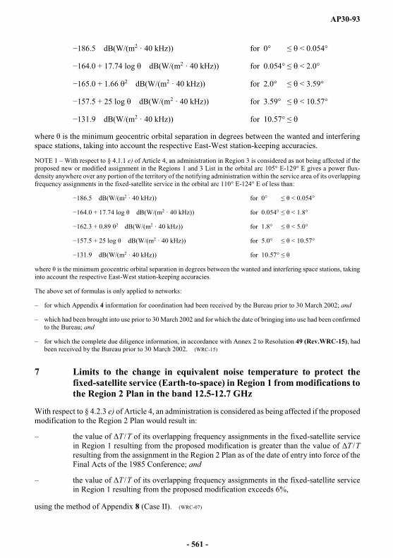
AP30-93
dB(W/(m2 · 40 kHz)) for 0° < 0.054°
+ 17.74 log dB(W/(m2 · 40 kHz)) for 0.054° < 2.0°
+ 1.66 2 dB(W/(m2 · 40 kHz)) for 2.0° < 3.59°
+ 25 log dB(W/(m2 · 40 kHz)) for 3.59° < 10.57°
131.9 dB(W/(m2 · 40 kHz)) for 10.57°
where minimum geocentric orbital separation in degrees between the wanted and interfering space stations, taking into account the respective East-West station-keeping accuracies.
NOTE 1 With respect to § 4.1.1 e) of Article 4, an administration in Region 3 is considered as not being affected if the proposed new or modified assignment in the Regions 1 and 3 List in the orbital arc 105° E-129° E gives a power flux-density anywhere over any portion of the territory of the notifying administration within the service area of its overlapping frequency assignments in the fixed-satellite service in the orbital arc 110° E-124° E of less than:
dB(W/(m2 · 40 kHz)) for 0° < 0.054°
dB(W/(m2 · 40 kHz)) for 0.054° < 1.8°
2 dB(W/(m2 · 40 kHz)) for 1.8° < 5.0°
dB(W/(m2 · 40 kHz)) for 5.0° < 10.57°
31.9 dB(W/(m2 · 40 kHz)) for 10.57°
into account the respective East-West station-keeping accuracies.
The above set of formulas is only applied to networks:
for which Appendix 4 information for coordination had been received by the Bureau prior to 30 March 2002; and
which had been brought into use prior to 30 March 2002 and for which the date of bringing into use had been confirmed to the Bureau; and
for which the complete due diligence information, in accordance with Annex 2 to Resolution 49 (Rev.WRC-15), had been received by the Bureau prior to 30 March 2002. (WRC-15)
7 Limits to the change in equivalent noise temperature to protect the fixed-satellite service (Earth-to-space) in Region 1 from modifications to the Region 2 Plan in the band 12.5-12.7 GHz
With respect to § 4.2.3 e) of Article 4, an administration is considered as being affected if the proposed modification to the Region 2 Plan would result in:
the value of T /T of its overlapping frequency assignments in the fixed-satellite service in Region 1 resulting from the proposed modification is greater than the value of T /Tresulting from the assignment in the Region 2 Plan as of the date of entry into force of the Final Acts of the 1985 Conference; and
the value of T /T of its overlapping frequency assignments in the fixed-satellite service in Region 1 resulting from the proposed modification exceeds 6%,
using the method of Appendix 8 (Case II). (WRC-07)
- 561 -
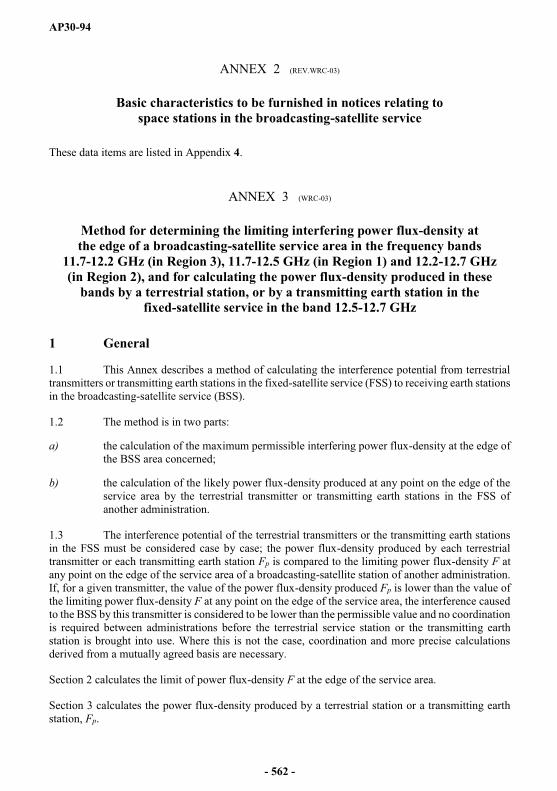
AP30-94
ANNEX 2 (REV.WRC-03)
Basic characteristics to be furnished in notices relating to space stations in the broadcasting-satellite service
These data items are listed in Appendix 4.
ANNEX 3 (WRC-03)
Method for determining the limiting interfering power flux-density at the edge of a broadcasting-satellite service area in the frequency bands
11.7-12.2 GHz (in Region 3), 11.7-12.5 GHz (in Region 1) and 12.2-12.7 GHz(in Region 2), and for calculating the power flux-density produced in these
bands by a terrestrial station, or by a transmitting earth station in the fixed-satellite service in the band 12.5-12.7 GHz
1 General
1.1 This Annex describes a method of calculating the interference potential from terrestrial transmitters or transmitting earth stations in the fixed-satellite service (FSS) to receiving earth stations in the broadcasting-satellite service (BSS).
1.2 The method is in two parts:
a) the calculation of the maximum permissible interfering power flux-density at the edge of the BSS area concerned;
b) the calculation of the likely power flux-density produced at any point on the edge of the service area by the terrestrial transmitter or transmitting earth stations in the FSS of another administration.
1.3 The interference potential of the terrestrial transmitters or the transmitting earth stations in the FSS must be considered case by case; the power flux-density produced by each terrestrial transmitter or each transmitting earth station Fp is compared to the limiting power flux-density F atany point on the edge of the service area of a broadcasting-satellite station of another administration. If, for a given transmitter, the value of the power flux-density produced Fp is lower than the value of the limiting power flux-density F at any point on the edge of the service area, the interference caused to the BSS by this transmitter is considered to be lower than the permissible value and no coordination is required between administrations before the terrestrial service station or the transmitting earth station is brought into use. Where this is not the case, coordination and more precise calculations derived from a mutually agreed basis are necessary.
Section 2 calculates the limit of power flux-density F at the edge of the service area.
Section 3 calculates the power flux-density produced by a terrestrial station or a transmitting earth station, Fp.
- 562 -
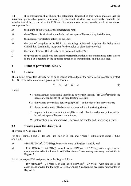
AP30-95
1.4 It is emphasized that, should the calculation described in this Annex indicate that the maximum permissible power flux-density is exceeded, it does not necessarily preclude the introduction of the terrestrial or the FSS since the calculations are necessarily based on worst-case assumptions for:
a) the nature of the terrain of the interference path;
b) the off-beam discrimination on the broadcasting-satellite receiving installations;
c) the necessary protection ratios for the BSS;
d) the type of reception in the BSS, i.e., assuming individual reception, this being more critical than community reception for the angles of elevation concerned;
e) the value of power flux-density to be protected in the BSS;
f) the propagation conditions between the terrestrial station or the transmitting earth station in the FSS operating in the opposite direction of transmission, and the BSS area.
2 Limit of power flux-density
2.1 General
The limiting power flux-density not to be exceeded at the edge of the service area in order to protect the BSS of an administration is given by the formula:
F = F0 R + D + P (1)
where:
F the maximum permissible interfering power flux-density (dB(W/m2)) within the necessary bandwidth of the broadcasting-satellite;
F0 the wanted power flux-density (dB(W/m2)) at the edge of the service area;
R the protection ratio (dB) between the wanted and interfering signals;
D angular antenna discrimination (dB) provided by the radiation pattern of the broadcasting-satellite receiver antenna;
P polarization discrimination (dB) between the wanted and interfering signals.
2.2 Wanted power flux-density (F0)
The value of F0 is equal to:
For the Regions 1 and 3 Plan and List, Region 2 Plan and Article 4 submissions under § 4.1.3 and 4.2.6:
a) dB(W/(m2 · 27 MHz)) for service areas in Regions 1 and 3, and
b) dB(W/(m2 · 24 MHz)), as well as in dB(W/(m2 · 27 MHz)) with respect to the cases mentioned in the footnote to § 3.8 of Annex 5 concerning necessary bandwidths in Region 2.
For the analogue BSS assignments in the Region 2 Plan:
dB(W/(m2 · 24 MHz)), as well as in dB(W/(m2 · 27 MHz)) with respect to the cases mentioned in the footnote to § 3.8 of Annex 5 concerning necessary bandwidths in Region 2.
- 563 -

AP30-96
2.3 Protection ratio (R)
2.3.1 For digital BSS assignments, the single entry protection ratio is equal to 30 dB.
2.3.2 For the analogue BSS assignments in the Region 2 Plan and for notified BSS assignments in Regions 1 and 3 Plan and List which are in conformity with the Plans and List of Appendix 30 and which have been brought into use and for which the date of bringing into use has been confirmed to the Bureau before 9 June 2003, the single entry protection ratio against all types of terrestrial transmissions, with the exception of amplitude-modulation multichannel television systems, is 35 dB for carrier frequency differences between the wanted and interfering signals of up to 0 MHz, decreasing linearly from 35 dB to 0 dB for carrier frequency differences between 10 MHz and 35 MHz, and is 0 dB for frequency differences in excess of 35 MHz (see Fig. 1). For amplitude-modulation multichannel television systems which produce high peaks of power flux-density spread over a wide range of their necessary bandwidth, the protection ratio R is 35 dB and is independent of the carrier frequency difference.
2.3.3 The carrier frequency difference should be determined by reference to the frequency assignments in the broadcasting-satellite Plan or, in the case of assignments not contained within a plan, by reference to the characteristics of the proposed or operational system.
2.3.4 A signal from a terrestrial station or a transmitting earth station in the FSS should be considered only if its necessary bandwidth overlaps the necessary bandwidth of the BSS assignment.
AP30A3-01
0 35302010
0
10
20
30
40
FIGURE 1Protection ratio (R) (dB) for a broadcasting-satellite signal
against a single entry of interference from a terrestrial service(except for AM multichannel TV system)
Protectionratio R (dB)
Carrier frequency difference f (MHz)
- 564 -
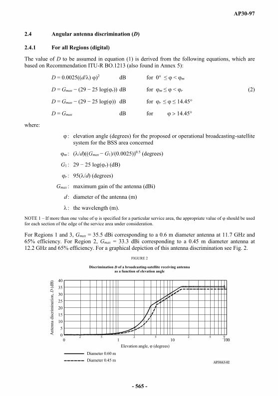
AP30-97
2.4 Angular antenna discrimination (D)
2.4.1 For all Regions (digital)
The value of D to be assumed in equation (1) is derived from the following equations, which are based on Recommendation ITU-R BO.1213 (also found in Annex 5):
D = 0.0025((d/ ) )2 dB < m
D = Gmax r)) dB for m < r (2)
D = Gmax )) dB for r
D = Gmax dB for 14.45°
where:
: elevation angle (degrees) for the proposed or operational broadcasting-satellite system for the BSS area concerned
m : ( /d)((Gmax G1)/(0.0025))0.5 (degrees)
G1 : r) (dB)
r : 95( /d) (degrees)
Gmax : maximum gain of the antenna (dBi)
d : diameter of the antenna (m)
: the wavelength (m).
NOTE 1 If more than one value of is specified for a particular service area, the appropriate value of should be used for each section of the edge of the service area under consideration.
For Regions 1 and 3, Gmax = 35.5 dBi corresponding to a 0.6 m diameter antenna at 11.7 GHz and 65% efficiency. For Region 2, Gmax = 33.3 dBi corresponding to a 0.45 m diameter antenna at 12.2 GHz and 65% efficiency. For a graphical depiction of this antenna discrimination see Fig. 2.
AP30A3-02
0
10
20
30
40
5
15
25
35
0 1 10 1002 5 92 52 5
Elevation angle, (degrees)
Ant
enna
disc
rimin
atio
n, D
(dB)
Diameter 0.60 mDiameter 0.45 m
FIGURE 2
Discrimination D of a broadcasting-satellite receiving antennaas a function of elevation angle
- 565 -
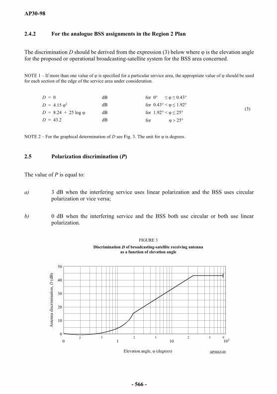
AP30-98
2.4.2 For the analogue BSS assignments in the Region 2 Plan
The discrimination D should be derived from the expression (3) below where is the elevation angle for the proposed or operational broadcasting-satellite system for the BSS area concerned.
NOTE 1 If more than one value of is specified for a particular service area, the appropriate value of should be used for each section of the edge of the service area under consideration.
D = 0 dB for 0° 0.43°
(3)D = 4.15 dB for 0.43° < 1.92°D = 8.24 + 25 log dB for 1.92° < 25°D = 43.2 dB for 25°
NOTE 2 For the graphical determination of D see Fig. 3. The unit for is degrees.
2.5 Polarization discrimination (P)
The value of P is equal to:
a) 3 dB when the interfering service uses linear polarization and the BSS uses circular polarization or vice versa;
b) 0 dB when the interfering service and the BSS both use circular or both use linear polarization.
AP30A3-03
0
10
20
30
40
50
10210102 5 2 5 2 5 9
FIGURE 3Discrimination D of broadcasting-satellite receiving antenna
as a function of elevation angle
Elevation angle, (degrees)
Ant
enna
dis
crim
inat
ion,
D (d
B)
- 566 -
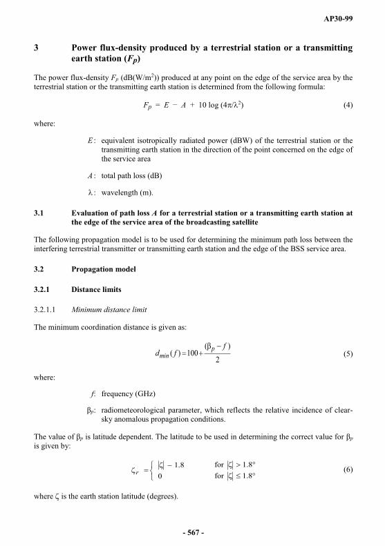
AP30-99
3 Power flux-density produced by a terrestrial station or a transmitting earth station (Fp)
The power flux-density Fp (dB(W/m2)) produced at any point on the edge of the service area by the terrestrial station or the transmitting earth station is determined from the following formula:
Fp = E A + 10 log (4 / 2) (4)
where:
E equivalent isotropically radiated power (dBW) of the terrestrial station or the transmitting earth station in the direction of the point concerned on the edge of the service area
A total path loss (dB)
: wavelength (m).
3.1 Evaluation of path loss A for a terrestrial station or a transmitting earth station at the edge of the service area of the broadcasting satellite
The following propagation model is to be used for determining the minimum path loss between the interfering terrestrial transmitter or transmitting earth station and the edge of the BSS service area.
3.2 Propagation model
3.2.1 Distance limits
3.2.1.1 Minimum distance limit
The minimum coordination distance is given as:
2
)(100)(
ffd p
min (5)
where:
f: frequency (GHz)
p: radiometeorological parameter, which reflects the relative incidence of clear-sky anomalous propagation conditions.
The value of p is latitude dependent. The latitude to be used in determining the correct value for pis given by:
8.1for8.1for
08.1
r (6)
where is the earth station latitude (degrees).
- 567 -

AP30-100
p is then determined using:
70orf17.470orf01 )015.067.1(
r
rp
r(7)
3.2.1.2 Maximum distance limit
The maximum distance, dmax, for paths comprising a single climatic zone must not exceed the value for that climatic zone given in the Table below. For mixed paths comprising multiple zones the overall maximum distance must not exceed the value in the Table below corresponding to the climatic zone in the mixed path having the largest value (e.g. for a mixed path comprising Zones A1 and A2, dmaxis 500 km).
3.2.2 Ducting model
3.2.2.1 Distance-independent part of the loss (dB) for ducting
For BSS earth stations, no additional protection due to the earth station horizon elevation angle can be assumed, i.e. Ah, the total terrain shielding attenuation, is 0 dB. However, if the detailed information for the transmitting station is known, including any site-shielding-based mitigation techniques that are used, all these factors need to be included in the determination of the coordination distance.
Reduction in attenuation arising from direct coupling into over-sea ducts (dB):
c
c dA
16
(8)
where dc (km) is the distance from a land-based transmitting station to the coast in the direction being considered. dc is zero in other circumstances.
Distance-independent part of the loss (dB) for ducting:
cAfA log5.1643.1221 (9)
Climatic Zone1 Maximum distance, dmax2
A1 500A2 375B 900C 1 200
1 For the definition see Appendix 7, § 1.5.1 and 1.5.3.2.2 As computed in § 2 of Appendix 7.
- 568 -
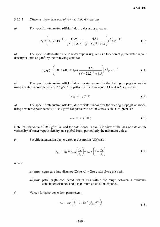
AP30-101
3.2.2.2 Distance-dependent part of the loss (dB) for ducting
a) The specific attenuation (dB/km) due to dry air is given as:
3222
30 10
50.1)57(81.4
227.009.610 19.7 f
ff(10)
b) The specific attenuation due to water vapour is given as a function of , the water vapour density in units of g/m3, by the following equation:
422 10
5.8)2.22(6.30021.0050.0)( f
fw (11)
c) The specific attenuation (dB/km) due to water vapour for the ducting propagation model using a water vapour density of 7.5 g/m3 for paths over land in Zones A1 and A2 is given as:
wdl = w (7.5) (12)
d) The specific attenuation (dB/km) due to water vapour for the ducting propagation model using a water vapour density of 10.0 g/m3 for paths over sea in Zones B and C is given as:
wds = w (10.0) (13)
Note that the value of 10.0 g/m3 is used for both Zones B and C in view of the lack of data on the variability of water vapour density on a global basis, particularly the minimum values.
e) Specific attenuation due to gaseous absorption (dB/km):
i
twds
i
twdlg d
ddd
10 (14)
where:
dt (km): aggregate land distance (Zone A1 + Zone A2) along the path;
di (km): path length considered, which lies within the range between a minimum calculation distance and a maximum calculation distance.
f ) Values for zone-dependent parameters:
41.24 )(10 12.4exp1 lmd (15)
- 569 -
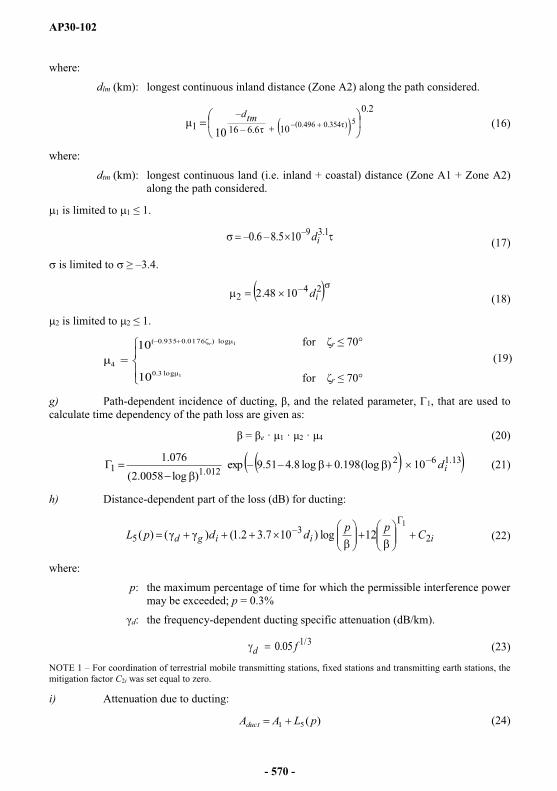
AP30-102
where:
dlm (km): longest continuous inland distance (Zone A2) along the path considered.
2.0
106.6 161 5)354.0496.0(10
tmd(16)
where:
dtm (km): longest continuous land (i.e. inland + coastal) distance (Zone A1 + Zone A2) along the path considered.
1 is limited to 1 1.
1.3105.86.0 id (17)
is limited to 3.4.
24
2 1048.2 id (18)
2 is limited to 2 1.
r
1
1
log3.0
log)0176.0935.0
4
10
10 r
r
(19)
g) Path- 1, that are used to calculate time dependency of the path loss are given as:
e 1 2 4 (20)
13.1621.0121 10) (log0.198 log 8.451.9exp
) log0058.2(076.1
id (21)
h) Distance-dependent part of the loss (dB) for ducting:
iiigd CppddpL 23
5 12 log )10 3.7 2.1( )()(1
(22)
where:
p: the maximum percentage of time for which the permissible interference power may be exceeded; p = 0.3%
d: the frequency-dependent ducting specific attenuation (dB/km).
3/105.0 fd (23)
NOTE 1 For coordination of terrestrial mobile transmitting stations, fixed stations and transmitting earth stations, the mitigation factor C2i was set equal to zero.
i) Attenuation due to ducting:
)(51 pLAAduct (24)
- 570 -
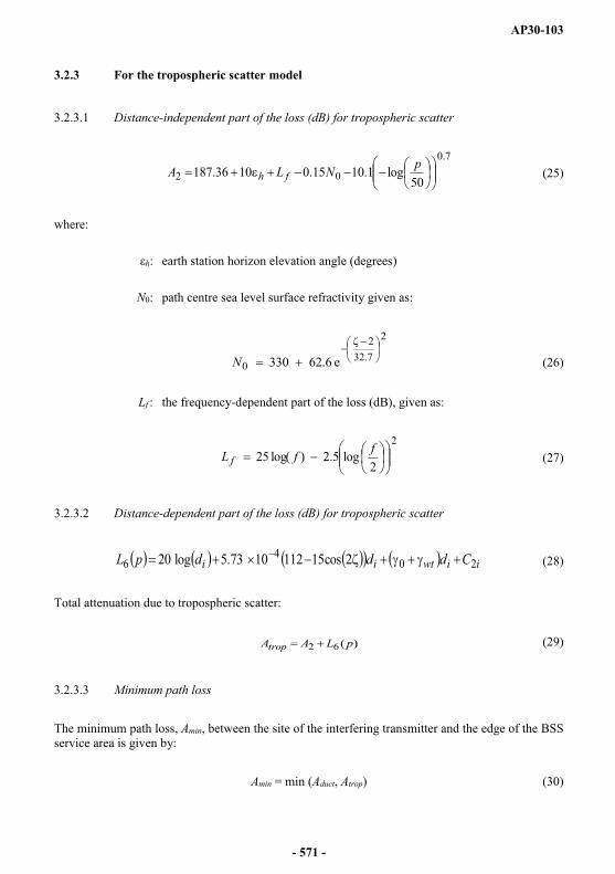
AP30-103
3.2.3 For the tropospheric scatter model
3.2.3.1 Distance-independent part of the loss (dB) for tropospheric scatter
7.0
02 50log1.1015.010 36.187 pNLA fh (25)
where:
h: earth station horizon elevation angle (degrees)
N0: path centre sea level surface refractivity given as:
2
7.322
0 e6.62330N (26)
Lf : the frequency-dependent part of the loss (dB), given as:
2
2log5.2)log(25 ffL f (27)
3.2.3.2 Distance-dependent part of the loss (dB) for tropospheric scatter
iiwtii CdddpL 204
6 2cos151121073.5log20 (28)
Total attenuation due to tropospheric scatter:
)(62 pLAAtrop (29)
3.2.3.3 Minimum path loss
The minimum path loss, Amin, between the site of the interfering transmitter and the edge of the BSS service area is given by:
Amin = min (Aduct, Atrop) (30)
- 571 -

AP30-104
ANNEX 4 (REV.WRC-15)
Need for coordination of a transmitting space station in the fixed-satellite service or in the broadcasting-satellite service where this service is not subject
to a Plan: in Region 2 (11.7-12.2 GHz) with respect to the Plan, the List or proposed new or modified assignments in the List for Regions 1 and 3; in Region 1 (12.5-12.7 GHz) and in Region 3 (12.2-12.7 GHz) with respect to the Plan or proposed modifications to the Plan in Region 2; in Region 3
(12.2-12.5 GHz) with respect to the Plan, List or proposed new or modified assignments in the List for Region 1
(See Article 7)
With respect to § 7.1 and 7.2 of Article 7, coordination of a transmitting space station in the fixed-satellite service (FSS) (space-to-Earth) of Region 2 or Region 3 is required when, under assumed free-space propagation conditions, the power flux-density over any portion of the service area of the overlapping frequency assignments in the BSS of an administration in Region 1 or Region 3 exceeds the following values: (WRC-07)
dB(W/(m2 27 MHz)) for 0° < 0.23°
+ 17.74 log dB(W/(m2 27 MHz)) for 0.23° < 2.0°
+ 1.66 dB(W/(m2 27 MHz)) for 2.0° < 3.59°
+ 25 log dB(W/(m2 27 MHz)) for 3.59° < 10.57°
dB(W/(m2 27 MHz)) for 10.57°
minimum geocentric orbital separation in degrees between the wanted and interfering space stations, taking into account the respective East-West station-keeping accuracies.
- 572 -
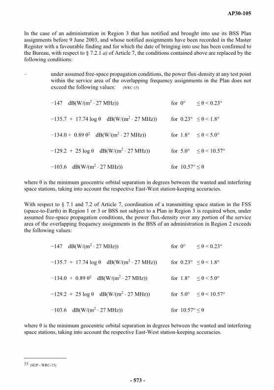
AP30-105
In the case of an administration in Region 3 that has notified and brought into use its BSS Plan assignments before 9 June 2003, and whose notified assignments have been recorded in the Master Register with a favourable finding and for which the date of bringing into use has been confirmed to the Bureau, with respect to § 7.2.1 a) of Article 7, the conditions contained above are replaced by the following conditions:
under assumed free-space propagation conditions, the power flux-density at any test point within the service area of the overlapping frequency assignments in the Plan does not exceed the following values:33 (WRC-15)
dB(W/(m2 27 MHz)) for 0° < 0.23°
+ 17.74 log dB(W/(m2 27 MHz)) for 0.23° < 1.8°
+ 0.89 dB(W/(m2 27 MHz)) for 1.8° < 5.0°
dB(W/(m2 27 MHz)) for 5.0° < 10.57°
dB(W/(m2 27 MHz)) for 10.57°
minimum geocentric orbital separation in degrees between the wanted and interfering space stations, taking into account the respective East-West station-keeping accuracies.
With respect to § 7.1 and 7.2 of Article 7, coordination of a transmitting space station in the FSS (space-to-Earth) in Region 1 or 3 or BSS not subject to a Plan in Region 3 is required when, under assumed free-space propagation conditions, the power flux-density over any portion of the service area of the overlapping frequency assignments in the BSS of an administration in Region 2 exceeds the following values:
dB(W/(m2 27 MHz)) for 0° < 0.23°
+ 17.74 log dB(W/(m2 27 MHz)) for 0.23° < 1.8°
+ 0.89 dB(W/(m2 27 MHz)) for 1.8° < 5.0°
+ 25 log dB(W/(m2 27 MHz)) for 5.0° < 10.57°
dB(W/(m2 27 MHz)) for 10.57°
minimum geocentric orbital separation in degrees between the wanted and interfering space stations, taking into account the respective East-West station-keeping accuracies.
_______________33 (SUP - WRC-15)
- 573 -

AP30-106
ANNEX 5
Technical data used in establishing the provisions and associated Plans and the Regions 1 and 3 List, which should be used
for their application34 (Rev.WRC-03)
1 Definitions
1.1 Downlink service area
The area on the surface of the Earth in which the administration responsible for the service has the right to demand that the agreed protection conditions be provided.
NOTE In the definition of service area, it is made clear that within the service area the agreed protection conditions can be demanded. This is the area where there should be at least the wanted power flux-density and protection against interference based on the agreed protection ratio for the agreed percentage of time.
1.2 Downlink coverage area
The area on the surface of the Earth delineated by a contour of a constant given value of power flux-density which would permit the wanted quality of reception in the absence of interference.
NOTE 1 In accordance with the provisions of No. 23.13, the coverage area must be the smallest area which encompasses the service area.
NOTE 2 The coverage area, which will normally encompass the entire service area, will result from the intersection of the antenna beam (elliptical, circular, or shaped) with the surface of the Earth, and will be defined by a given value of power flux-density. For example, it would be the area delineated by the contour corresponding to the level specified in § 3.16 of this Annex. There will usually be an area outside the service area but within the coverage area in which the power flux-density will be at least equivalent to the minimum specified value; however, protection against interference will not be provided in this area.
NOTE 3 If coverage is provided by a steerable beam, the contour delineating the coverage area will depend on the pointing capability of the beam and will not necessarily cover the entire service area.
1.3 Downlink beam area
The area delineated by the intersection of the half-power beam of the satellite transmitting antenna with the surface of the Earth. The downlink beam area concept was generally used for planning purposes in conjunction with elliptical beams.
NOTE 3 dB points on the satellite antenna radiation pattern. In many cases the beam area would almost coincide with the coverage area, the discrepancy being accounted for by the permanent difference in path lengths from the satellite throughout the beam area, and also by the permanent variations, if any, in propagation factors across the area. However, for a service area where the maximumdimension as seen from the satellite position is less than 0.6° in Regions 1 and 3, and less than 0.8° in Region 2(the agreed minimum practicable satellite antenna half-power beamwidths), there could be a significant difference between the beam area and the coverage area.
_______________34 In revising this Annex at WRC-97 and at WRC-2000, no changes have been made to the technical data applicable to the Region 2 Plan. However, for all three Regions, it should be noted that some of the parameters of networks proposed as modifications to the Region 2 Plan and the Regions 1 and 3 List may differ from the technical data presented herein. (WRC-2000)
- 574 -
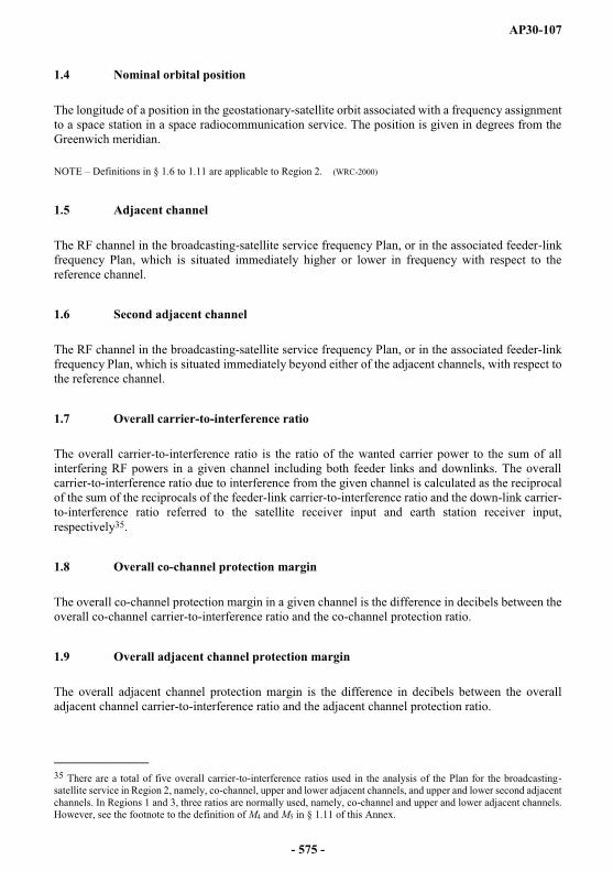
AP30-107
1.4 Nominal orbital position
The longitude of a position in the geostationary-satellite orbit associated with a frequency assignment to a space station in a space radiocommunication service. The position is given in degrees from the Greenwich meridian.
NOTE Definitions in § 1.6 to 1.11 are applicable to Region 2. (WRC-2000)
1.5 Adjacent channel
The RF channel in the broadcasting-satellite service frequency Plan, or in the associated feeder-link frequency Plan, which is situated immediately higher or lower in frequency with respect to the reference channel.
1.6 Second adjacent channel
The RF channel in the broadcasting-satellite service frequency Plan, or in the associated feeder-link frequency Plan, which is situated immediately beyond either of the adjacent channels, with respect to the reference channel.
1.7 Overall carrier-to-interference ratio
The overall carrier-to-interference ratio is the ratio of the wanted carrier power to the sum of all interfering RF powers in a given channel including both feeder links and downlinks. The overall carrier-to-interference ratio due to interference from the given channel is calculated as the reciprocal of the sum of the reciprocals of the feeder-link carrier-to-interference ratio and the down-link carrier-to-interference ratio referred to the satellite receiver input and earth station receiver input, respectively35.
1.8 Overall co-channel protection margin
The overall co-channel protection margin in a given channel is the difference in decibels between the overall co-channel carrier-to-interference ratio and the co-channel protection ratio.
1.9 Overall adjacent channel protection margin
The overall adjacent channel protection margin is the difference in decibels between the overall adjacent channel carrier-to-interference ratio and the adjacent channel protection ratio.
_______________35 There are a total of five overall carrier-to-interference ratios used in the analysis of the Plan for the broadcasting-satellite service in Region 2, namely, co-channel, upper and lower adjacent channels, and upper and lower second adjacent channels. In Regions 1 and 3, three ratios are normally used, namely, co-channel and upper and lower adjacent channels. However, see the footnote to the definition of M4 and M5 in § 1.11 of this Annex.
- 575 -
AP30-108
1.10 Overall second adjacent channel protection margin
The overall second adjacent channel protection margin is the difference in decibels between the overall second adjacent channel carrier-to-interference ratio and the second adjacent channel protection ratio.
1.11 Overall equivalent protection margin36
The overall equivalent protection margin, M, is given in decibels by the expression:
5
1
10/10log10i
M iM
where:
M1 overall co-channel protection margin (dB) (as defined in § 1.8);
M2, M3 overall adjacent channel protection margins for the upper and lower adjacent channels, respectively (dB) (as defined in § 1.9);
M4, M5 overall second adjacent channel protection margins for the upper and lower second adjacent channels, respectively (dB) (as defined in § 1.10)37.
gins for all interference sources from the adjacent and second adjacent channels as well as co-channel interference sources have been included. (WRC-2000)
2 Radio propagation factors
In Regions 1 and 3:
2.1 The propagation loss on the space-to-Earth path (used for computing downlink e.i.r.p. and as a guide in choosing orbital locations during the development of the Plan) is equal to the free-space path loss plus the atmospheric absorption and the rain attenuation exceeded for 1% of the worst month. Values of this attenuation can be calculated as a function of angle of elevation for the rain-climatic zones shown in Figs. 1 and 2 from Recommendation ITU-R P.837-1 by applying the method described in Recommendation ITU-R P.618-5.
_______________36 For calculation of overall equivalent protection margin for Regions 1 and 3, as defined at WARC Orb-88, see alternative formula in § 1.12 to Annex 3 of Appendix 30A.
37 M4 and M5 are applicable only for Region 2. (WRC-2000)
- 576 -
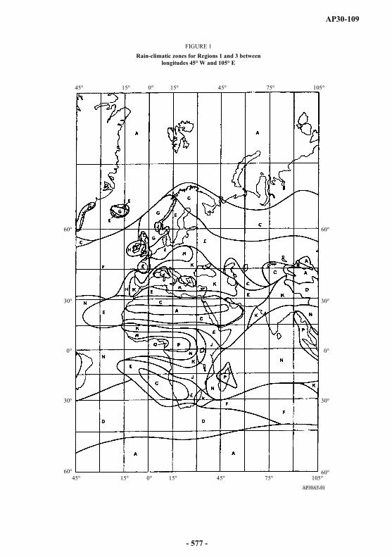
AP30-109
AP30A5-01
45° 15° 0° 15° 45° 75° 105°
30°
0°
30°
60°
60°45° 15° 0° 15° 45° 75° 105°
30°
0°
30°
60°
60°
FIGURE 1Rain-climatic zones for Regions 1 and 3 between
longitudes 45° W and 105° E
- 577 -
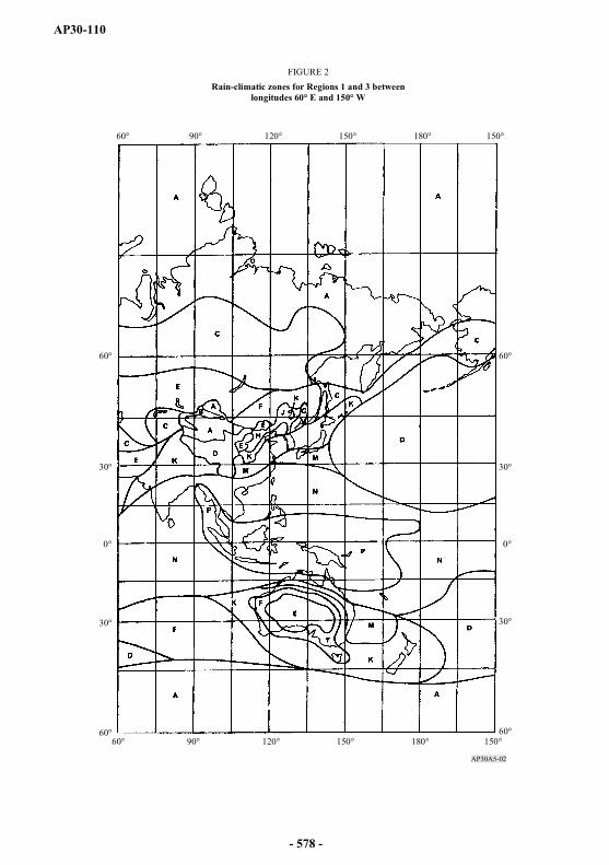
AP30-110
AP30A5-02
60° 90° 120° 150° 180° 150°
30°
0°
30°
60°
60°60° 90° 120° 150° 180° 150°
30°
0°
30°
60°
60°
FIGURE 2Rain-climatic zones for Regions 1 and 3 between
longitudes 60° E and 150° W
- 578 -
AP30-111
In Region 2:
2.2 The propagation loss on a space-Earth path is equal to the free-space path loss plus the atmospheric absorption loss plus the rain attenuation exceeded for 1% of the worst month.
2.2.1 Atmospheric absorption
The loss due to atmospheric absorption (i.e. clear-sky attenuation) is given by:
woa FFA 002.0017.0cos
20.92 dB for < 5°
where:
1
2 51.5tan77.4161339.0tan88.24oF
1
2 51.5tan66.8113339.0tan81.40wF
and:
sin
003.0042.0aA dB for 5°
where:
elevation angle (degrees),
surface water vapour concentration (g/m3), being
= 10 g/m3 for rain climatic zones A to K and
= 20 g/m3 for rain climatic zones M to P (see Fig. 3).
2.2.2 Rain attenuation
The rain attenuation Ap of circularly polarized signals exceeded for 1% of the worst month at 12.5 GHz is given by:
rLAp 21.0 dB (31)
where:
L: slant path length through rain
sin5008
2sin
221
02
0
hh
hh
R
R km
- 579 -
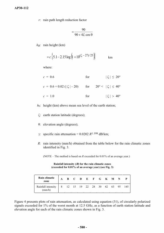
AP30-112
r: rain path length reduction factor
cos49090L
hR: rain height (km)
25/)27(101log15.21.5c km
where:
c = 0.6 for | | 20°
c = 0.6 + 0.02 (| | 20) for 20° < | | 40°
c = 1.0 for | | 40°
h0: height (km) above mean sea level of the earth station;
: earth station latitude (degrees);
: elevation angle (degrees);
: specific rain attenuation = 0.0202 R1.198 dB/km;
R: rain intensity (mm/h) obtained from the table below for the rain climatic zones identified in Fig. 3.
(NOTE The method is based on R exceeded for 0.01% of an average year.)
Rainfall intensity (R) for the rain climatic zones (exceeded for 0.01% of an average year) (see Fig. 3)
Figure 4 presents plots of rain attenuation, as calculated using equation (31), of circularly polarized signals exceeded for 1% of the worst month at 12.5 GHz, as a function of earth station latitude and elevation angle for each of the rain climatic zones shown in Fig. 3.
Rain climatic zone
A B C D E F G K M N P
Rainfall intensity(mm/h)
8 12 15 19 22 28 30 42 63 95 145
- 580 -

AP30-113
2.2.3 Rain attenuation limit
In the analysis of the Plan for the broadcasting-satellite service in Region 2, a maximum downlink attenuation of 9 dB was agreed in order to limit the inhomogeneity of broadcasting-satellite power flux-density and to facilitate sharing during clear-sky conditions.
- 581 -
AP30-114
2.2.4 Procedure for calculating the carrier-to-interference ratio at a test point
The calculation of the down-link carrier-to-interference ratio (exceeded for 99% of the worst month) used to obtain the overall equivalent protection margin at a test point is the minimum value of the carrier-to-interference ratio obtained assuming:
i) clear-sky conditions (i.e. including atmospheric absorption); or
ii) rain-faded conditions corresponding to an attenuation value exceeded for 1% of the worst month.
2.3 Depolarization
Rain and ice can cause depolarization of radio frequency signals. The level of the co-polar component relative to the depolarized component is given by the cross-polarization discrimination (XPD) ratio. For circularly polarized emissions, the XPD ratio (dB) exceeded for 99% of the worst month is obtained from:
pAfXPD log20)(coslog40log30 for 5° 60° (32)
where Ap (dB) is the co-polar rain attenuation exceeded for 1% of the worst month (calculated in § 2.2), f is the frequency in GHz and is the elevation angle. For angles of greater than 60°,use = 60° in equation (32).
- 582 -

AP30-115
AP30A5-04a
0
1
80706050403020100 900
2
1
80706050403020100 90
0
2
1
80706050403020100 900
3
1
2
80706050403020100 90
4030 50
2060
3050
2060
70
4030 50
6060
70
50
80
FIGURE 4Rain attenuation values exceeded for 1% of the worst month
(sea level) for Region 2 rain-climatic zones
Elevation angle (degrees)
Atte
nuat
ion
(dB
)
Zone AFreq. 12.5 GHz
Latitude (degrees)
a) Rain-climatic zone A
Zone BFreq. 12.5 GHz
Latitude (degrees)A
ttenu
atio
n (d
B)
b) Rain-climatic zone B
Elevation angle (degrees)
Elevation angle (degrees)
Atte
nuat
ion
(dB
)
Zone CFreq. 12.5 GHz
Latitude (degrees)
c) Rain-climatic zone C
Zone DFreq. 12.5 GHz
Latitude (degrees)
Atte
nuat
ion
(dB
)
d) Rain-climatic zone D
Elevation angle (degrees)
- 583 -

AP30-116
AP30A5-04b
0
3
2
1
80706050403020100 900
4
2
1
3
80706050403020100 90
0
4
1
2
3
80706050403020100 900
6
2
4
1
3
5
80706050403020100 90
3050
2060
70
3050
60
3040
60
50
40
20
40
FIGURE 4 (continued)Rain attenuation values exceeded for 1% of the worst month
(sea level) for Region 2 rain-climatic zones
Elevation angle (degrees)
Atte
nuat
ion
(dB
)
Zone EFreq. 12.5 GHz
Latitude (degrees)
e) Rain-climatic zone E
Zone FFreq. 12.5 GHz
Latitude (degrees)
Atte
nuat
ion
(dB
)
f) Rain-climatic zone F
Elevation angle (degrees)
Elevation angle (degrees)
Atte
nuat
ion
(dB
)
Zone GFreq. 12.5 GHz
Latitude (degrees)
g) Rain-climatic zone G
Zone KFreq. 12.5 GHz
Latitude (degrees)
Atte
nuat
ion
(dB
)
h) Rain-climatic zone K
Elevation angle (degrees)
- 584 -
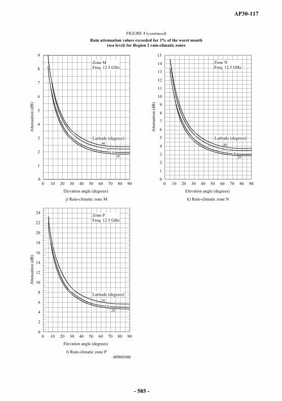
AP30-117
AP30A5-04c
0
9
6
3
1
2
4
5
7
8
80706050403020100 900
15
8
1
11
2
3
4
5
6
7
9
10
12
13
14
80706050403020100 90
0
2
4
6
8
10
12
14
16
18
20
22
24
80706050403020100 90
30
20
300
20
3040
0
40
20
0
FIGURE 4 (continued)Rain attenuation values exceeded for 1% of the worst month
(sea level) for Region 2 rain-climatic zones
Elevation angle (degrees)
Atte
nuat
ion
(dB
)
Zone MFreq. 12.5 GHz
Latitude (degrees)
j) Rain-climatic zone M
Zone NFreq. 12.5 GHz
Latitude (degrees)
Atte
nuat
ion
(dB
)
k) Rain-climatic zone N
Elevation angle (degrees)
Elevation angle (degrees)
Atte
nuat
ion
(dB
)
Zone PFreq. 12.5 GHz
Latitude (degrees)
l) Rain-climatic zone P
- 585 -
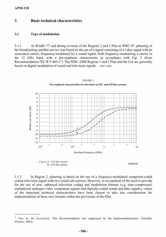
AP30-118
3 Basic technical characteristics
3.1 Type of modulation
3.1.1 At WARC-77 and during revision of the Regions 1 and 3 Plan at WRC-97, planning of the broadcasting-satellite service was based on the use of a signal consisting of a video signal with an associated carrier, frequency-modulated by a sound signal, both frequency-modulating a carrier in the 12 GHz band, with a pre-emphasis characteristic in accordance with Fig. 5 (from Recommendation ITU-R F.405-1*). The WRC-2000 Regions 1 and 3 Plan and the List are generally based on digital modulation of sound and television signals. (WRC-2000)
3.1.2 In Region 2, planning is based on the use of a frequency-modulated composite-coded colour television signal with two sound sub-carriers. However, in recognition of the need to provide for the use of new, enhanced television coding and modulation formats (e.g. time-compressed, multiplexed analogue video component signals and digitally-coded sound and data signals), values of the important technical characteristics have been chosen to take into consideration the implementation of these new formats within the provisions of the Plan.
_______________* Note by the Secretariat: This Recommendation was suppressed by the Radiocommunication Assembly (Geneva, 2003).
AP30A5-05
1011052 52 52
10
20
468
10
A
B
FIGURE 5Pre-emphasis characteristic for television on 525- and 625-line systems
Baseband frequency (MHz)
Rel
ativ
e de
viat
ion
(dB
)
Curves A: 525-line system B: 625-line system
- 586 -

AP30-119
3.1.3 Nevertheless, other modulating signals having different characteristics (e.g. modulation with sound channels frequency-multiplexed within the bandwidth of a television channel, digital modulation of sound and television signals, or other pre-emphasis characteristics) are not precluded, provided that appropriate protection masks and calculation methods38 are applied or if the use of such characteristics complies with the provisions of § 3.2 of Article 3.
3.2 Polarization
3.2.1 For the planning of the broadcasting-satellite service, circular polarization is generally used. However, for implementation of assignments in the Plan, linear polarization may also be used, subject to the successful application of the modification procedure of Article 4.
3.2.2 In Regions 1 and 3, the polarization of different beams intended to serve the same area should, if possible, be the same.
3.2.3 Thcircularly-polarized waves correspond to right-hand (clockwise) and left-hand (anti-clockwise) polarization respectively according to the following definitions:
Direct polarization (right-hand or clockwise polarization):
An elliptically or circularly-polarized electromagnetic wave, in which the electric field-intensity vector, observed in any fixed plane, normal to the direction of propagation, whilst looking in (i.e., not against) the direction of propagation, rotates with time in a right-hand or clockwise direction.
NOTE For right-hand circularly-polarized plane waves, the ends of the electric vectors drawn from any points along a straight line normal to the plane of the wave front form, at any instant, a left-hand helix.
Indirect polarization (left-hand or anti-clockwise polarization):
An elliptically or circularly-polarized electromagnetic wave, in which the electric field-intensity vector, observed in any fixed plane, normal to the direction of propagation, whilst looking in (i.e., not against) the direction of propagation, rotates with time in a left-hand or anti-clockwise direction.
NOTE For left-hand circularly-polarized plane waves, the ends of the electric vectors drawn from any points along a straight line normal to the plane of the wave front form, at any instant, a right-hand helix.
3.2.4 Linear polarization is defined in Recommendation ITU-R BO.1212. This Recommendation should be used when analysing linearly polarized signals.
_______________38 Protection masks for verifying that this provision is met are not yet fully defined in existing ITU-R Recommendations. Recommendations for interference between analogue and digital signals are still under development. In absence of criteria to evaluate interference, the Bureau will use the worst-case approach as adopted by the Radio Regulations Board.
- 587 -

AP30-120
3.3 Carrier-to-noise ratio
For the purpose of planning the broadcasting-satellite service, the carrier-to-noise ratio is equal to or exceeds 14 dB for 99% of the worst month.
In Regions 1 and 3, the reduction in quality in the down-link due to thermal noise in the feeder-link is taken as equivalent to a degradation in the down-link carrier-to-noise ratio not exceeding 0.5 dB for 99% of the worst month. In Region 2, as a guide for planning, the reduction in quality in the down-link due to thermal noise in the feeder link is taken as equivalent to a degradation in the down-link carrier-to-noise ratio of approximately 0.5 dB not exceeded for 99% of the worst month, but the feeder-link and down-link Plans are evaluated on the basis of the overall carrier-to-noise ratio of 14 dB for the combined down-link and feeder-link contributions.
3.4 Protection ratio between television signals
For developing the original 1977 broadcasting-satellite service Plan for Regions 1 and 3, the following protection ratios were used39, 40:
31 dB for co-channel signals;
15 dB for adjacent channel signals.
For revising this Plan at WRC-97, the following aggregate downlink protection ratios were specified in Recommendation ITU-R BO.1297 for the purpose of calculating downlink equivalent protection margins40, 41, 42:
24 dB for co-channel signals;
16 dB for adjacent channel signals.
_______________39 These protection ratio values were used for the assignments notified, which are in conformity with this Appendix, brought into use, and for which the date of bringing into use has been confirmed to the Bureau before 27 October 1997.
40 The equivalent protection margin M is given in dB by the formula:
M 1/10 + 10 2/10 + 10 3/10)
where M1 is the value (dB) of the protection margin for the same channel. This is defined in the following expression where the powers are evaluated at the receiver input:
wanted powersum of the co-channel
interfering powers
(dB) co-channel protection ration (dB)
M2 and M3 are the values (dB) of the upper and lower adjacent-channel protection margins respectively.
The definition of the adjacent-channel protection margin is similar to that for the co-channel case except that the adjacent-channel protection ratio and the sum of the interfering powers due to emissions in the adjacent channel are considered.
41 These protection ratio values were used for the assignments notified, which are in conformity with this Appendix, brought into use, and for which the date of bringing into use has been confirmed to the Bureau between 27 October 1997 and 12 May 2000. (WRC-2000)
42 These protection ratio values were used for protection of digital and analogue assignments from analogue emissions. (WRC-2000)
- 588 -
AP30-121
In revising the Regions 1 and 3 Plan at WRC-97, the following aggregate overall protection ratio values were used for calculating the overall co-channel and adjacent-channel protection margins as defined in § 1.8 and 1.9:
23 dB for co-channel signals;
15 dB for adjacent channel signals.
It was also specified that for the revision of the Regions 1 and 3 Plan, no overall co-channel single entry C/I should be lower than 28 dB.
However, for the assignments notified, which are in conformity with this Appendix, brought into use, and for which the date of bringing into use has been confirmed to the Bureau before 27 October 1997, the overall equivalent protection margins were calculated using a co-channel overall protection ratio of 30 dB and lower and upper overall adjacent channel protection ratios of 14 dB43.
WRC-2000 adopted, for the protection of digital assignments from digital emissions, the following protection ratio values to be applied for calculation of downlink equivalent protection margins of the WRC-2000 Regions 1 and 3 Plan:
21 dB for co-channel signals;
16 dB for adjacent channel signals.
During planning at WRC-2000, these values were used for all assignments of the Regions 1 and 3Plan and List except those for which WRC-2000 adopted different values used in the planning process44.
Revision of the Regions 1 and 3 Plan at WRC-97 and planning at WRC-2000 were generally based on a set of reference parameters such as the average e.i.r.p., the reference earth station receiving
dB contour, a bandwidth of 27 MHz and the predetermined value of C/N. The Regions 1 and 3 Plan as established by WRC-2000 is generally based on the use of digital modulation.
Protection masks and associated calculation methods for interference into broadcasting satellite systems involving digital emissions shall be in accordance with Recommendation ITU-R BO.1293-2 (Annexes 1 and 245).
In Region 2, the following protection ratios have been adopted for the purpose of calculating the overall equivalent protection margin46:
28 dB for co-channel signals;
13.6 dB for adjacent-channel signals;
9.9 dB for second adjacent-channel signals.
_______________43 The overall protection margin calculation method used is based on the first formula in § 1.12 of Annex 3 to Appendix 30A.
44 For analogue assignments, the protection ratios adopted by WRC-97 were used (24 dB co-channel and 16 dB adjacent channel). (WRC-2000)
45 Annex 3 of this Recommendation may be applied only in compatibility analysis for bilateral coordination between administrations. (WRC-03)
46 The definitions in § 1.7, 1.8, 1.9, 1.10 and 1.11 of this Annex apply to these calculations. (WRC-03)
- 589 -
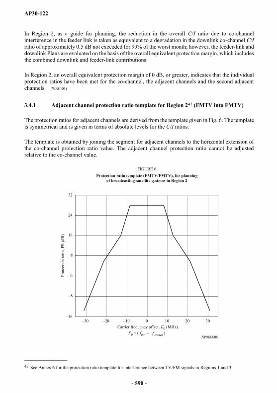
AP30-122
In Region 2, as a guide for planning, the reduction in the overall C/I ratio due to co-channel interference in the feeder link is taken as equivalent to a degradation in the downlink co-channel C/Iratio of approximately 0.5 dB not exceeded for 99% of the worst month; however, the feeder-link and downlink Plans are evaluated on the basis of the overall equivalent protection margin, which includes the combined downlink and feeder-link contributions.
In Region 2, an overall equivalent protection margin of 0 dB, or greater, indicates that the individual protection ratios have been met for the co-channel, the adjacent channels and the second adjacent channels. (WRC-03)
3.4.1 Adjacent channel protection ratio template for Region 247 (FMTV into FMTV)
The protection ratios for adjacent channels are derived from the template given in Fig. 6. The template is symmetrical and is given in terms of absolute levels for the C/I ratios.
The template is obtained by joining the segment for adjacent channels to the horizontal extension of the co-channel protection ratio value. The adjacent channel protection ratio cannot be adjusted relative to the co-channel value.
_______________47 See Annex 6 for the protection ratio template for interference between TV/FM signals in Regions 1 and 3.
AP30A5-06
0 2010 30
0
8
16
24
32
Carrier frequency offset, F0 (MHz)F0 = ( fint fwanted )
Prot
ectio
n ra
tio, P
R (d
B)
FIGURE 6Protection ratio template (FMTV/FMTV), for planning
of broadcasting-satellite systems in Region 2
- 590 -
AP30-123
The template is given by the following expressions:
PR =
28 dB for | F0 | 8.36 MHz
| F0 | + 51.09 dB for 8.36 < | F0 | 12.87 MHz
| F0 | + 30.4 dB for 12.87 < | F0 | 21.25 MHz
| F0 | + 48.38 dB for | F0 | > 21.25 MHz
where PR is the protection ratio (dB) and |F0 | is the carrier spacing between the interfering and wanted signals (MHz).
3.5 Channel spacing
3.5.1 Channel spacing in the Plans
In Regions 1 and 3, the spacing between the assigned frequencies of two adjacent channels is 19.18 MHz.
In Region 2, the spacing between the assigned frequencies of two adjacent channels is 14.58 MHz, which corresponds to 32 channels in the 500 MHz bandwidth allocated to the broadcasting-satellite service.
The Plans give the assigned frequencies for each channel.
However, in the Regions 1 and 3 Plan, for the implementation of assignments different frequency spacing may be used subject to the successful application of the modification procedure of Article 4,ITU-R Recommendations for protection masks should be used if available. In the absence of such Recommendations, the Bureau should apply the worst-case approach as adopted by the Radio Regulations Board.
3.5.2 Arrangement of channels in the same beam
Planning in Region 1 at the 1977 Conference was carried out by trying to restrict all the channels radiated within a single antenna beam within a frequency range of 400 MHz, in order to simplify receiver construction. Such a restriction was considered unnecessary for the revision of the Regions 1and 3 Plan at WRC-97.
3.5.3 Spacing between assigned channel frequencies feeding a common antenna
In the 1977 Plan for Regions 1 and 3, owing to technical difficulties in the output circuit of a satellite transmitter, spacing between the assigned frequencies of two channels feeding a common antenna was required to be greater than 40 MHz. This restriction was not imposed in the revision of the Plan.
- 591 -
AP30-124
3.6 Figure of merit (G/T) of a receiving station in the broadcasting-satellite service
In planning the broadcasting-satellite service, the value of the figure of merit G/T for clear-sky conditions is:
for Regions 1 and 3:
The original 1977 broadcasting-satellite service Plan used values48 of:
6 dB(K ) for individual reception
14 dB(K ) for community reception, and
for Region 2:
10 dB(K ) for individual reception.
The 1997 revision of the Regions 1 and 3 Plan is based on a uniform value of the figure of merit G/Tequal to 11 dB(K ).
These values were calculated from a formula which allows for pointing error, polarization effects and equipment ageing.
See also Report ITU-R BO.473-3 (Annex 1).
3.7 Receiving antennas
3.7.1 Half-power beamwidth of receiving antennas
In the development of the original 1977 broadcasting-satellite service Plan for Regions 1 and 3, the minimum receiving antenna diameter was such that the half-power beamwidth was 2° for individual reception and 1° for community reception.
In revising this Plan at WRC-97, the minimum receiving antenna diameter was such that the half-power beamwidth was 2.86°. (WRC-07)
For planning the broadcasting-satellite service in Region 2, the minimum receiving antenna diameter must be such that the half- 0 is 1.7°.
_______________48 These values are still used for assignments notified, which are in conformity with this Appendix, brought into use, and for which the date of bringing into use has been confirmed to the Bureau before 27 October 1997.
- 592 -
AP30-125
3.7.2 Receiving antenna reference patterns
The co-polar and cross-polar receiving antenna reference patterns are given in Figs. 7, 7bis and 8.
a) For Regions 1 and 3, the original 1977 Conference Plan was based on the antenna pattern49 shown in Fig. 7 where the relative antenna gain (dB) is given by the curves for:
individual reception, for which use should be made of:
Curve A for the co-polar component;
Curve B for the cross-polar component;
community reception, for which use should be made of:
Curve A up to the intersection with Curve C, then Curve C, for the co-polar component;
Curve B for the cross-polar component.
The WRC-97 revision of the Regions 1 and 3 broadcasting-satellite service Plan was based on the absolute gain (dBi) patterns for a 60 cm antenna given in Recommendation ITU-R BO.1213 as shown in Fig. 7bis.
b) For Region 2, the relative antenna gain (dB) is given by the curves in Fig. 8 for individual reception, for which use should be made of:
Curve A for the co-polar component;
Curve B for the cross-polar component.
_______________49 This antenna pattern is used in the broadcasting-satellite service Plan for Regions 1 and 3 for assignments notified, which are in conformity with this Appendix, brought into use, and for which the date of bringing into use has been confirmed to the Bureau before 27 October 1997.
- 593 -
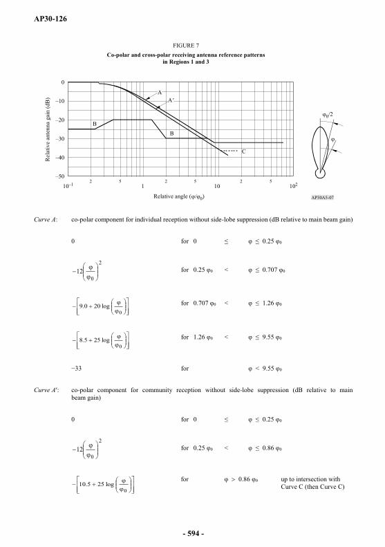
AP30-126
Curve A: co-polar component for individual reception without side-lobe suppression (dB relative to main beam gain)
0 for 0 0.25 0
2
012 for 0 < 0
0log200.9 for 0 < 0
0log255.8 for 0 < 0
for < 0
Curve A : co-polar component for community reception without side-lobe suppression (dB relative to main beam gain)
0 for 0 0
2
012 for 0 < 0
0log255.10
for 0.86 0 up to intersection with Curve C (then Curve C)
AP30A5-07
0
10210110525252
0/2
AA'
BB
C
FIGURE 7Co-polar and cross-polar receiving antenna reference patterns
in Regions 1 and 3
Relative angle ( 0)
Rel
ativ
e an
tenn
a ga
in (d
B)
- 594 -
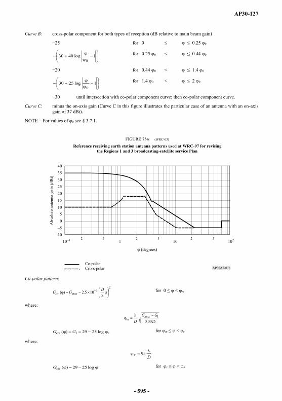
AP30-127
Curve B: cross-polar component for both types of reception (dB relative to main beam gain)
for 0 0
1log40300
for 0 < 0
for 0 < 0
1log25300
for 0 < 0
until intersection with co-polar component curve; then co-polar component curve.
Curve C: minus the on-axis gain (Curve C in this figure illustrates the particular case of an antenna with an on-axis gain of 37 dBi).
NOTE For values of 0 see § 3.7.1.
Co-polar pattern:
23105.2)( DGG maxco
for 0 < m
where:
0025.01GG
Dmax
m
rco GG log2529)( 1 for m < r
where:
Dr 95
log2529)(coG for r < b
AP30A5-07b
40353025201510
50
2 5 2 5 2 510 1 1 10 102
Abs
olut
e an
tenn
a ga
in (d
Bi)
(degrees)
Co-polarCross-polar
FIGURE 7bis (WRC-03)
Reference receiving earth station antenna patterns used at WRC-97 for revising the Regions 1 and 3 broadcasting-satellite service Plan
- 595 -
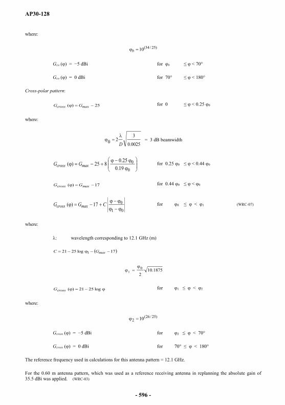
AP30-128
where:
)25/34(10b
Gco ( ) = dBi for b < 70°
Gco ( ) = 0 dBi for 70° < 180°
Cross-polar pattern:
25)( maxcross GG for 0 < 0.25 0
where:
0025.0
320 D
= 3 dB beamwidth
0
019.0
25.0825)( maxcross GG for 0.25 0 < 0.44 0
17)( maxcross GG for 0.44 0 < 0
01
017)( CGG maxcross for 0 < 1 (WRC-07)
where:
wavelength corresponding to 12.1 GHz (m)
17log2521 1 maxGC
1875.1020
1
log2521)(crossG for 1 < 2
where:
)25/26(2 10
Gcross ( ) = dBi for 2 < 70°
Gcross ( ) = 0 dBi for 70° < 180°
The reference frequency used in calculations for this antenna pattern = 12.1 GHz.
For the 0.60 m antenna pattern, which was used as a reference receiving antenna in replanning the absolute gain of 35.5 dBi was applied. (WRC-03)
- 596 -
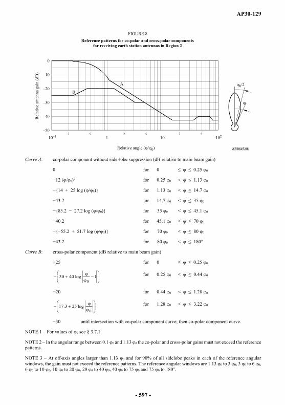
AP30-129
Curve A: co-polar component without side-lobe suppression (dB relative to main beam gain)
0 for 0 0.25 0
/ 0)2 for 0.25 0 < 1.13 0
+ 25 log ( / 0)} for 1.13 0 < 14.7 0
for 14.7 0 < 35 0
/ 0)} for 35 0 < 45.1 0
for 45.1 0 < 70 0
+ 51.7 log ( / 0)} for 70 0 < 80 0
for 80 0 < 180°
Curve B: cross-polar component (dB relative to main beam gain)
for 0 0.25 0
1log40300
for 0.25 0 < 0.44 0
for 0.44 0 < 1.28 0
0log253.17 for 1.28 0 < 3.22 0
until intersection with co-polar component curve; then co-polar component curve.
NOTE 1 For values of 0 see § 3.7.1.
NOTE 2 In the angular range between 0.1 0 and 1.13 0 the co-polar and cross-polar gains must not exceed the reference patterns.
NOTE 3 At off-axis angles larger than 1.13 0 and for 90% of all sidelobe peaks in each of the reference angular windows, the gain must not exceed the reference patterns. The reference angular windows are 1.13 0 to 3 0, 3 0 to 6 0,6 0 to 10 0, 10 0 to 20 0, 20 0 to 40 0, 40 0 to 75 0 and 75 0 to 180°.
AP30A5-08
0
10210110525252
0/2A
B
FIGURE 8Reference patterns for co-polar and cross-polar components
for receiving earth station antennas in Region 2
Relative angle ( / 0)
Rel
ativ
e an
tenn
a ga
in (d
B)
- 597 -
AP30-130
3.8 Necessary bandwidth
WARC-77 Regions 1 and 3 Plan and the WRC-97 revision of the Regions 1 and 3 Plan used the following:
625-line systems in Regions 1 and 3: 27 MHz;
525-line systems in Region 3: 27 MHz. (WRC-2000)
The planning at WRC-2000 was generally based on a necessary bandwidth of 27 MHz. (WRC-2000)
In Region 2, the Plan is based on a channel bandwidth of 24 MHz50, but different bandwidths may be implemented in accordance with the provisions of this Appendix, provided that applicable ITU-RRecommendations are available. In the absence of such Recommendations, the Bureau will use the worst-case approach. (WRC-2000)
If different bandwidths and/or channel spacing are submitted, they will be treated in accordance with applicable ITU-R Recommendations for protection masks when available. In the absence of such Recommendations, the Bureau will use the worst-case approach. (WRC-2000)
3.9 Guardbands
3.9.1 A guardband is defined as the portion of the frequency spectrum between the edge of the allocated band and the edge of the necessary bandwidth of the emission in the nearest channel.
3.9.2 For the planning of the broadcasting-satellite service, the guardbands chosen at the 1977 Conference to protect the services in adjacent frequency bands are shown in the Table below.
For Regions 1 and 3 at WARC-77, the guardbands were derived on the assumption of analogue emissions and a maximum beam centre e.i.r.p. of 67 dBW (value relating to individual reception), and a filter roll-off of 2 dB/MHz. If smaller e.i.r.p. values are assumed, the guardbands can be reduced in width by 0.5 MHz for each decibel decrease in e.i.r.p. The degree of possible reduction also depends on improvements in technology and on the type of modulation. (WRC-2000)
_______________50 For France, Denmark and some of the United Kingdom requirements which use 625-line standards with greater video bandwidth, the channels shown in the Plan have a necessary bandwidth of 27 MHz. This is indicated by an appropriate symbol in the Plan.
Regions Guardband at the lower edge of the band
(MHz)
Guardband at the upper edge of the band
(MHz)
1 14 112 12 123 14 11
- 598 -
AP30-131
3.9.3 (SUP - WRC-97)
3.9.4 The guardbands at both the lower and upper edges may be used to provide space operation functions in accordance with No. 1.23 in support of the operation of geostationary-satellite networks in the broadcasting-satellite service. (WRC-03)
3.10 Orbital spacing
The Plan for Regions 1 and 3 has been based generally on nominal orbital positions spaced uniformly at intervals of 6°. The Plan for Region 2 has been based on a non-uniform spacing.
3.11 Satellite station-keeping
Space stations in the broadcasting-satellite service must be maintained in position with an accuracy equal to or better than 0.1° in the E-W directions. For such space stations, the maintenance of the tolerance 0.1° in the N-S direction is recommended but is not a requirement.
3.12 Elevation angle of receiving antennas
The Plans have been based on the desirability of a minimum angle of elevation of 20° to minimize the required e.i.r.p. of the satellite and to reduce the effects of shadowing and the possibility of interference from terrestrial services. However, for areas situated in latitudes above about 60°, the angle of elevation is of necessity less than 20°. Attention is also drawn to § 2.1 for the Regions 1and 3 Plan and to § 2.2.3 for the Region 2 Plan.
For mountainous areas where an elevation angle of 20° may not suffice, an angle of at least 30° has been provided, where possible, to provide an acceptable service. An angle of elevation of at least 40° has been considered for service areas subject to high precipitation, but exceptions were made in some cases in Region 2.
Some dry, non-mountainous areas may be given an acceptable service at angles of elevation less than 20°.
In areas with small elevation angles, the shadowing effect of tall buildings may have to be taken into account.
In choosing a satellite position designed to give the maximum angle of elevation at the ground, the influence of such a position on the eclipse period was taken into account at the 1977 Conference. In the revision of the Regions 1 and 3 Plan at WRC-97, this influence was not considered to be a significant constraint on the choice of orbital position.
- 599 -
AP30-132
3.13 Transmitting antennas
3.13.1 Cross-section of transmitted beam
Planning in Regions 1, 2 and 3 has been generally based on the use of satellite transmitting antennas with beams of elliptical cross-section.
If the cross-section of the emitted beam is elliptical, the effective beamwidth 0 is a function of the angle of rotation between the plane containing the satellite and the major axis of the beam cross-section and the plane in which the beamwidth is required.
The relationship between the maximum gain of an antenna and the half-power beamwidth can be derived from the expression:
ab
Gm84327
where:
a and b are the angles (degrees) subtended at the satellite by the major and minor axes of the elliptical cross-section of the beam; an antenna efficiency of 55% was assumed.
However, in implementing their assignments, administrations can choose beams other than elliptical, as described in Annex 2 to this Appendix, subject to successful application of the modification procedure of this Appendix.
3.13.2 Minimum beamwidth of transmitting antenna
A minimum value of 0.6° for the half-power beamwidth of a transmitting antenna has been adopted for planning for Regions 1 and 3, and 0.8° for Region 2.
3.13.3 Transmitting antenna reference patterns
The reference patterns for the co-polar and cross-polar components of satellite transmitting antennas used in preparing the Plans are given in Fig. 9 for Regions 1 and 3, and in Fig. 10 for Region 2.
- 600 -
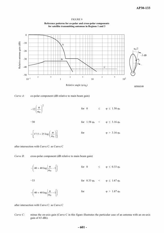
AP30-133
Curve A: co-polar component (dB relative to main beam gain)
2
012 for 0 1.58 0
for 1.58 0 < 3.16 0
0log255.17 for > 3.16 0
after intersection with Curve C: as Curve C
Curve B: cross-polar component (dB relative to main beam gain)
1log40400
for 0 0.33 0
for 0.33 0 < 1.67 0
1log40400
for > 1.67 0
after intersection with Curve C: as Curve C
Curve C: minus the on-axis gain (Curve C in this figure illustrates the particular case of an antenna with an on-axis gain of 43 dBi).
AP30A5-09
0
10210110525252
0/2A
B
C
FIGURE 9Reference patterns for co-polar and cross-polar components
for satellite transmitting antennas in Regions 1 and 3
Relative angle ( 0
Rel
ativ
e an
tenn
a ga
in (d
B)
- 601 -
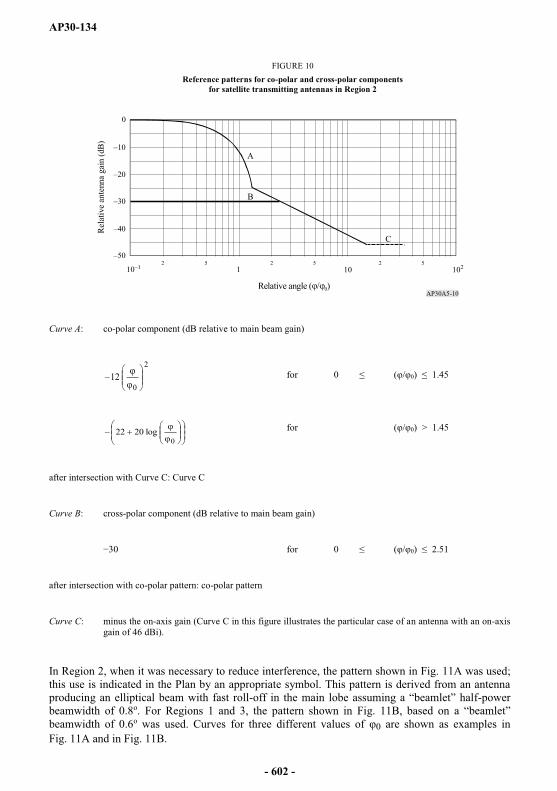
AP30-134
Curve A: co-polar component (dB relative to main beam gain)
2
012 for 0 ( 0) 1.45
0log2022 for ( 0) > 1.45
after intersection with Curve C: Curve C
Curve B: cross-polar component (dB relative to main beam gain)
for 0 ( 0) 2.51
after intersection with co-polar pattern: co-polar pattern
Curve C: minus the on-axis gain (Curve C in this figure illustrates the particular case of an antenna with an on-axis gain of 46 dBi).
In Region 2, when it was necessary to reduce interference, the pattern shown in Fig. 11A was used; this use is indicated in the Plan by an appropriate symbol. This pattern is derived from an antenna producing an elliptical beam with fast roll- -power beamwidth of 0.8o. For Regions 1 and 3, the pattern shown in Fig. beamwidth of 0.6o was used. Curves for three different values of 0 are shown as examples in Fig. 11A and in Fig. 11B.
AP30A5-10
0
2 5 2 5 2 51 10 10210
B
C
A
Rel
ativ
e an
tenn
a ga
in (d
B)
Relative angle ( 0)
FIGURE 10Reference patterns for co-polar and cross-polar components
for satellite transmitting antennas in Region 2
- 602 -

AP30-135
Curve A: co-polar component (dB relative to main beam gain)
2
012 for 0 ( / 0) 0.5
2
0
012minB
xfor 0.5 < ( / 0) xBmin
0
45.1
for xBmin0
45.1 < ( 0) 1.45
0log2022 0) > 1.45
after intersection with Curve C: Curve C
Curve B: cross-polar component (dB relative to main beam gain)
for 0 ( 0) < 2.51
after intersection with co-polar pattern: co-polar pattern
AP30A5-11A
A
C
0
1010 12 5 2 5 2 5
B
Rela
tive
ante
nna
gain
(dB)
Relative angle ( 0)
FIGURE 11AReference patterns for co-polar and cross-polar components for satellite
transmitting antennas with roll-off in the main beam for Region 2
- 603 -
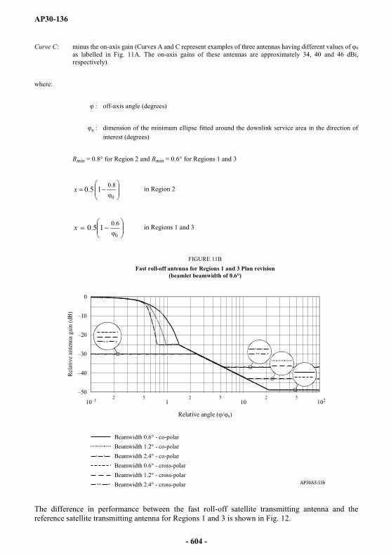
AP30-136
Curve C: minus the on-axis gain (Curves A and C represent examples of three antennas having different values of 0as labelled in Fig. 11A. The on-axis gains of these antennas are approximately 34, 40 and 46 dBi, respectively).
where:
: off-axis angle (degrees)
0 : dimension of the minimum ellipse fitted around the downlink service area in the direction of interest (degrees)
Bmin = 0.8° for Region 2 and Bmin = 0.6° for Regions 1 and 3
0
8.015.0x in Region 2
0
6.015.0x in Regions 1 and 3
The difference in performance between the fast roll-off satellite transmitting antenna and the reference satellite transmitting antenna for Regions 1 and 3 is shown in Fig. 12.
AP30A5-11b
0
2 5 2 5 2 51 10210 10
Rela
tive
ante
nna
gain
(dB)
Relative angle ( 0)
Beamwidth 0.6° - co-polarBeamwidth 1.2° - co-polarBeamwidth 2.4° - co-polarBeamwidth 0.6° - cross-polarBeamwidth 1.2° - cross-polarBeamwidth 2.4° - cross-polar
FIGURE 11BFast roll-off antenna for Regions 1 and 3 Plan revision
(beamlet beamwidth of 0.6°)
- 604 -
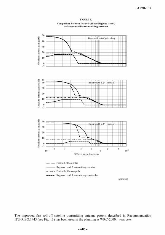
AP30-137
The improved fast roll-off satellite transmitting antenna pattern described in Recommendation ITU-R BO.1445 (see Fig. 13) has been used in the planning at WRC-2000. (WRC-2000)
AP30A5-12
1 10 102102 5 2 5 2 5
40
30
20
10
0
40
30
20
10
0
45
40
30
20
10
0
50
Fast roll-off co-polarRegions 1 and 3 transmitting co-polarFast roll-off cross-polar
Regions 1 and 3 transmitting cross-polar
Beamwidth 0.6° (circular)
Beamwidth 1.2° (circular)
Beamwidth 2.4° (circular)
Off-axis angle (degrees)
Abs
olut
e an
tenn
a ga
in (d
Bi)
Abs
olut
e an
tenn
a ga
in (d
Bi)
Abs
olut
e an
tenn
a ga
in (d
Bi)
FIGURE 12Comparison between fast roll-off and Regions 1 and 3
reference satellite transmitting antennas
- 605 -

AP30-138
Curve A: co-polar relative gain (dB relative to main beam gain):
21,min GGG
where:
201 )(12 /G ( / 0
2
0
0121minB
xG for 0.5 < ( / 0 xBmin
0
45.1(WRC-2000)
0
A
B
C
G2
G2
G2
G2
G1G1
1 1010 102
Rel
ativ
e an
tenn
a ga
in (d
B)
Off-axis angle, (degrees)
FIGURE 13 (Rev.WRC-03)
Improved fast roll-off satellite transmittingantenna pattern for Regions 1 and 3
Improved fast roll-off co-polar (Curve A defined as G below)Regions 1 and 3 transmitting co-polar (Curve G2)Improved fast roll-off cross-polar (Regions 1 and 3 transmitting cross-polar) (Curve B)
Regions 1 and 3 transmitting fast roll-off co-polar (Curve G1)
Curve C (minus the on-axis gain)
Note 1 of 0 = 1.2° (circular). AP30A5-13
- 606 -
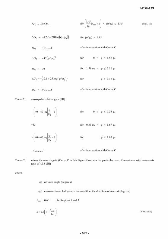
AP30-139
23.251G for xBmin0
45.1< ( / 0) 1.45 (WRC-03)
01 /log2022G for ( 0) 1.45
axis-onGG1 after intersection with Curve C
202 /12G for 0 1.58 0
302G for 1.58 0 < 3.16 0
)/(log255.17 02G for 3.16 0
axis-onGG2 after intersection with Curve C
Curve B: cross-polar relative gain (dB):
1log40400
for 0 0.33 0
for 0.33 0 < 1.67 0
1log40400
for 1.67 0
axisonG - after intersection with Curve C
Curve C: minus the on-axis gain (Curve C in this Figure illustrates the particular case of an antenna with an on-axis gain of 42.8 dBi)
where:
off-axis angle (degrees)
0: cross-sectional half-power beamwidth in the direction of interest (degrees)
Bmin: 0.6° for Regions 1 and 3
015.0 minBx (WRC-2000)
- 607 -

AP30-140
3.13.4 Composite beam
A composite beam represents a single beam (i.e. combining two or more elliptical beams at a given orbital position. In general, composite beams were used at WRC-2000 for administrations which had more than one beam at a given orbital position in the WRC-97 Regions 1 and 3 Plan. (WRC-2000)
3.14 Satellite antenna pointing accuracy
3.14.1 The deviation of the antenna beam from its nominal pointing direction must not exceed a limit of 0.1° in any direction. Moreover, the angular rotation of a transmitting beam about its axis must not exceed a limit of 1°; the limit on rotation is not necessary for beams of circular cross-section using circular polarization51.
3.14.2 The following factors contribute to the total variation in the area on the surface of the Earth illuminated by the satellite beam:
variations in satellite station-keeping;
the variations caused by the pointing tolerances, which become more significant for coverage areas with low angles of elevation;
the effect of the yaw error, which increases as the beam ellipse lengthens.
3.14.3 The effect of these possible variations should be assessed on a case-by-case basis, since their total effect on the area covered will vary with the geometry of the satellite beam, and it would not be reasonable to indicate a single value of shift in the area covered for all situations.
3.14.4 If linear polarization is used for an emission, yaw error makes a significant contribution to increasing the transmitted cross-polarized component; this increases the interference with other carriers which were originally cross-polarized with the emission in question.
3.15 Limitation of output power in the satellite transmitter
The output power of a space station transmitter in the broadcasting-satellite service must not rise by more than 0.25 dB relative to its nominal value throughout the life of the satellite.
_______________51 In the original 1977 broadcasting-satellite service Plan for Regions 1 and 3, the angular rotation of a transmitting beam about its axis must not exceed a limit of ±2°. This limit is still applied for assignments notified, which are in conformity with this Appendix, brought into use, and for which the date of bringing into use has been confirmed to the Bureau before 27 October 1997.
- 608 -
AP30-141
3.16 Power flux-density at edge of coverage area
The original 1977 broadcasting-satellite service Plan used the following values52 of the power flux-density at the edge of the coverage area exceeded for 99% of the worst month:
dB(W/m2) for individual reception in Regions 1 and 3;
dB(W/m2) for individual reception in Region 2 for 24 MHz, as well as for 27 MHz with respect to the cases mentioned in the footnote to § 3.8.
dB(W/m2) for community reception in Regions 1 and 3.
The 1997 revision of the Regions 1 and 3 Plan was generally based on a uniform value of the power flux-density at the edge of coverage area equal to 108 dB(W/m2). This corresponds to the general reduction in e.i.r.p. of 5 dB referenced to the average e.i.r.p. of 63.9 dBW in the 1977 broadcasting-satellite service Plan.
3.17 Difference between the e.i.r.p. directed towards the edge of the coverage area and that on the axis of the beam
For planning, the absolute value of the difference between the e.i.r.p. directed towards the edge of the coverage area and that on the axis of the beam should preferably be 3 dB.
If the beam area is larger than the coverage area, the value will be less than 3 dB.
3.18 Use of energy dispersal
For planning, an energy dispersal value has been adopted which reduces by 22 dB the spectral power flux-density measured in a 4 kHz bandwidth in relation to that measured in the entire bandwidth: For frequency-modulated television signals, this reduction corresponds to a peak-to-peak deviation of 600 kHz. Digital modulation can achieve appropriate energy dispersal by proper implementation of digital modulation (e.g. by applying spectrum scrambling and/or interleaving).
3.19 Orbital separation limit for interference calculation
WRC-2000 has adopted the use of an orbital separation limit for interference calculation in Regions 1 and 3. Beyond this limit no interference was taken into account.
Initially, the values used for the orbital separation limit were 15° for co-polar and 9° for cross-polar emissions. At a later stage, the unique value of the orbital separation limit of 9° was adopted by WRC-2000. (WRC-2000)
_______________52 These values are still used for assignments notified, which are in conformity with this Appendix, brought into use, and for which the date of bringing into use has been confirmed to the Bureau before 27 October 1997.
- 609 -

AP30-142
ANNEX 653 (WRC-03)
Criteria for sharing between services
Part A Technical bases for the criteria for interregional sharing between space services in Annexes 1 and 4
The revised interregional sharing criteria in the bands governed by Appendix 30 are based nominally on the following assumptions.
1 Reference assumptions regarding earth station antenna patterns
1.1 For earth station antennas with diameters between 0.45 m and 2.40 m, the gain of the side lobes given by Recommendation ITU-R BO.1213 were used.
For the patterns of earth station antennas with diameters greater than 2.40 m, the gain of the side lobes given by Recommendation ITU-R S.580-5, with a (29 25 log ) side-lobe envelope, complemented by the main-lobe given in Annex 3 to Appendix 8, were used. is the off-axis angle in degrees.
1.2 For the broadcasting-satellite service and fixed-satellite service earth stations, an antenna efficiency of 65% was used at a frequency of 11.7 GHz.
2 Antenna diameters and noise temperatures
The range of antenna diameters and associated noise temperatures considered for the protection of the fixed-satellite service and the broadcasting-satellite service on an interregional basis are given in the following table:
_______________53 Sections 1 and 2 are applicable when the services of Regions 1 or 3 are involved. Section 3 is applicable to all Regions.
Receive earth station antenna diameter (m) 0.45 1 0.60 0.80 1.20 2.40 5 2 8 2 11 2
Receive earth station noise temperature (K) 110 110 125 150 150 200 250 250
Total link noise temperature (K) 174 174 198 238 238 317 396 396
1 This antenna diameter applies in certain cases (see Annexes 1, 3 and 4).2 This antenna diameter does not apply for broadcasting-satellite service.
- 610 -

AP30-143
The total link noise temperature was calculated from the receive earth station noise temperature (which includes the antenna temperature, the receive amplifier temperature and the noise increase resulting from feeder losses), and adding 2 dB to take account of all other sources of noise (uplink noise, geostationary-satellite orbit interference, cross polarization isolation and frequency reuse interference).
3 Protection criteria
The power flux-density masks developed in sections 1, 3 and 6 of Annex 1 and in Annex 4 have been determined by setting at 6% the allowable relative noise increase ( T/T), for the earth station antenna characteristics given in the above Table.
The allowable interfering power flux-density was calculated by the following expression:
)(log10/log10)( amrfall GGbTkTTPFD
where:
PFDall allowable level of interfering power flux-density for an orbital separation of °
T/T: allowable relative increase in receive link noise = 6%
k: × 10 J/K)
T: receive link noise temperature (K) (see Table in section 2 above)
brf : reference bandwidth (27 MHz in Regions 1 and 3; 24 MHz in Region 2)
Gm: gain for a 1 m2 effective aperture (dBi/m2)
Ga
topocentric angle (degrees) between the interfering and the wanted satellite, as defined in Annex 1 of Appendix 8.
4 Power flux-density levels for fixed-satellite service and broadcasting-satellite service with specific antenna diameters
The table below contains power flux-density levels derived for fixed-satellite service and broadcasting-satellite service earth stations with specific antenna diameters for the characteristics defined in sections 1, 2 and 3 above. These levels were used to develop the power flux-density masks in sections 1, 3 and 6 of Annex 1 and in Annex 4 by taking the envelope of the individual pfd masks for the relevant antenna diameters.
- 611 -
AP30-144
Part B Sharing criteria used in establishing the WARC SAT-77 Plan
1 Protection requirements for sharing between services in the 12 GHz band
1.1 The establishment of sharing criteria for the different services using the 12 GHz band should be based on the protection requirements listed in the table below.
1.2
The for each source may not guarantee that the total interference meets the above protection requirements.
ssions from any one station entering any receiver in the wanted service within the channel to be protected.
1.3 The carrier-to-interference ratio (C/I) refers to the ratio of the wanted-to-interfering power at the affected ground station. The value given shall be exceeded for 80% of the worst month for the fixed-satellite service, and for 99% of the worst month for the broadcasting service and the broadcasting-satellite service.
1.4 The term N refers to the post-demodulation noise power at a point of 0 dBm0 relative test tone level in any voice channel of an FDM/FM telephony system. The value given shall not be exceeded for 80% of the worst month.
Orbital separation between wanted and
interfering space stations
(degrees)
Power flux-density level in dB(W/(m2 · 27 MHz)) corresponding to different antenna diameters
0.45 m 1 0.60 m 0.80 m 1.20 m 2.40 cm 5 m 2 8 m 2 11 m 2
0° 134.2 136.7 138.7 141.4 147.4 152.5 155.7 158.4
0° For any value of the orbital separation between the wanted and interfering space stations, the applicable power flux-density should be relaxed from the value corresponding to 0° orbital separation by adding the off-axis antenna discrimination, as calculated under the assumptions in section 1 above
1 This antenna diameter applies to certain cases (see Annexes 1, 3 and 4).2 This antenna diameter does not apply for broadcasting satellite service.
- 612 -
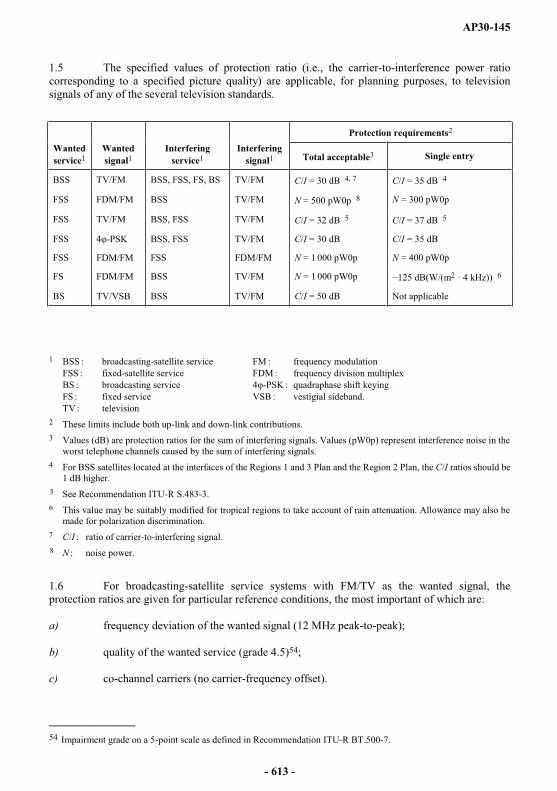
AP30-145
1.5 The specified values of protection ratio (i.e., the carrier-to-interference power ratio corresponding to a specified picture quality) are applicable, for planning purposes, to television signals of any of the several television standards.
Protection requirements2
Wanted service1
Wanted signal1
Interfering service1
Interfering signal1 Total acceptable3 Single entry
BSS TV/FM BSS, FSS, FS, BS TV/FM C/I = 30 dB 4, 7 C/I = 35 dB 4
FSS FDM/FM BSS TV/FM N = 500 pW0p 8 N = 300 pW0p
FSS TV/FM BSS, FSS TV/FM C/I = 32 dB 5 C/I = 37 dB 5
FSS 4 -PSK BSS, FSS TV/FM C/I = 30 dB C/I = 35 dB
FSS FDM/FM FSS FDM/FM N = 1 000 pW0p N = 400 pW0p
FS FDM/FM BSS TV/FM N = 1 000 pW0p dB(W/(m2 · 4 kHz)) 6
BS TV/VSB BSS TV/FM C/I = 50 dB Not applicable
1 BSS broadcasting-satellite service FM frequency modulationFSS fixed-satellite service FDM frequency division multiplexBS broadcasting service 4 -PSK quadraphase shift keyingFS fixed service VSB vestigial sideband.TV television
2 These limits include both up-link and down-link contributions.3 Values (dB) are protection ratios for the sum of interfering signals. Values (pW0p) represent interference noise in the
worst telephone channels caused by the sum of interfering signals.4 For BSS satellites located at the interfaces of the Regions 1 and 3 Plan and the Region 2 Plan, the C/I ratios should be
1 dB higher.5 See Recommendation ITU-R S.483-3.6 This value may be suitably modified for tropical regions to take account of rain attenuation. Allowance may also be
made for polarization discrimination.7 C/I ratio of carrier-to-interfering signal.8 N noise power.
1.6 For broadcasting-satellite service systems with FM/TV as the wanted signal, the protection ratios are given for particular reference conditions, the most important of which are:
a) frequency deviation of the wanted signal (12 MHz peak-to-peak);
b) quality of the wanted service (grade 4.5)54;
c) co-channel carriers (no carrier-frequency offset).
_______________54 Impairment grade on a 5-point scale as defined in Recommendation ITU-R BT.500-7.
- 613 -
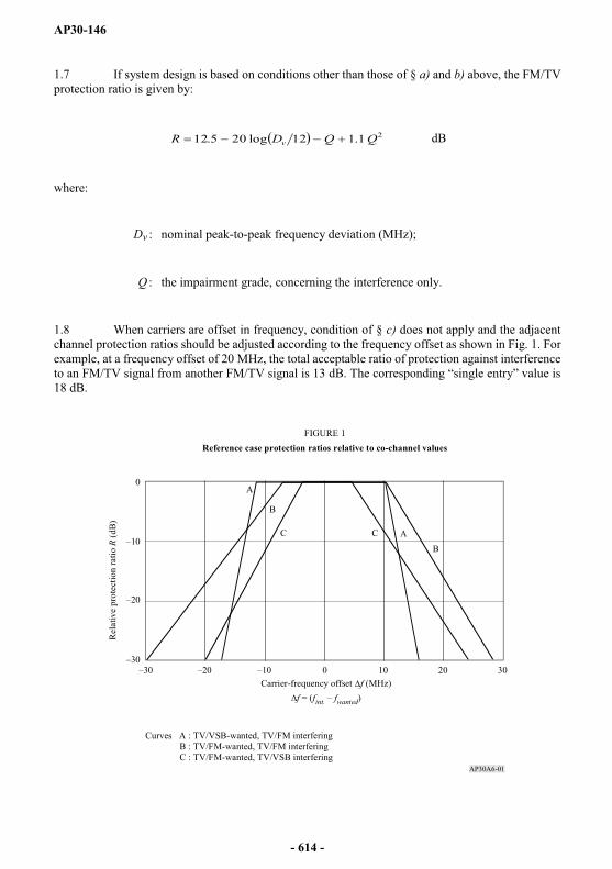
AP30-146
1.7 If system design is based on conditions other than those of § a) and b) above, the FM/TV protection ratio is given by:
21.112log205.12 QQDR v dB
where:
Dv nominal peak-to-peak frequency deviation (MHz);
Q the impairment grade, concerning the interference only.
1.8 When carriers are offset in frequency, condition of § c) does not apply and the adjacent channel protection ratios should be adjusted according to the frequency offset as shown in Fig. 1. For example, at a frequency offset of 20 MHz, the total acceptable ratio of protection against interference to an FM/TV signal from another FM/TV signal is 13 18 dB.
AP30A6-01
A
AB
B
C C
0 10 20 30
0
FIGURE 1Reference case protection ratios relative to co-channel values
Carrier-frequency offset f (MHz)f = (fint. fwanted)
Rel
ativ
e pr
otec
tion
ratio
R (d
B)
Curves A : TV/VSB-wanted, TV/FM interfering B : TV/FM-wanted, TV/FM interfering C : TV/FM-wanted, TV/VSB interfering
- 614 -
AP30-147
2 Reference antenna diameter for a fixed-satellite earth station to be used in calculating interference from space stations in the broadcasting-satellite service
2.1 For antennas larger than 100 (2.5 m) in the fixed-satellite service, the gain of the side-lobes is given by the expression 32 25 log , where is the angle from the boresight (Recommendation ITU-R S.465-5). The side-lobe gain is independent of antenna diameter.
2.2 However, in the case of transmitting earth stations, the level of interference radiated into the up-link of other satellite systems would be inversely proportional to the square of the antenna diameter. In this case, the interference decreases with increasing antenna diameter. Since the 11.7-12.2 GHz band is only assigned in the space-to-Earth direction in the fixed-satellite service, this point is not of direct concern to the broadcasting-satellite service.
2.3 Hence it does not appear appropriate, for antenna diameters greater than 100 , to specify a minimum antenna diameter for receiving earth stations in the fixed-satellite service sharing the band 11.7-12.2 GHz. It may be useful to consider a 4.5 m antenna having an efficiency of 60% and an on-axis gain of 53 dB as typical for the purpose of planning the sharing of this band.
3 Use of energy dispersal in the broadcasting-satellite service
3.1 Artificial energy dispersal is useful in promoting sharing between the broadcasting-satellite service and the other services to which the band is also allocated.
3.2 Such energy dispersal is achieved by the addition at baseband of a triangular waveform to the video signal to form a composite baseband which, in turn, is used to frequency-modulate the up-link carrier. The frequency of the triangular waveform is usually synchronized at a sub-multiple of the television frame frequency. Typical frequencies range from 12.5 Hz to 30 Hz.
3.3 The Table below gives the relative reduction in spectral power flux-density in a 4 kHz bandwidth as a function of the peak-to-peak deviation due to the energy dispersal signal. This Table is based on the following equation:
Relative reduction (dB) in a 4 kHz band = 4
log10 rmspp fF
where:
Fpp peak-to-peak deviation due to the energy dispersal signal (kHz);
frms
- 615 -

AP30-148
In compiling the table below, a value of 40 kHz has been assumed for frms, on the basis of the value of 10 dB for IV of ex-CCIR Report 631* (Rev.76).
Reduction of spectral power flux-density relative to a 4 kHz bandwidth
Peak-to-peak deviation(kHz)
Relative reduction(dB)
0100200300400500600700800900
1 000
1015.4417.7819.2920.4121.3022.0422.6723.2223.7124.15
3.4 The value of energy dispersal for the broadcasting-satellite service has been determined such that the spectral power flux-density measured in a 4 kHz bandwidth is reduced by 22 dB relative to that measured in the entire bandwidth; this reduction corresponds to a peak-to-peak deviation of 600 kHz.
ANNEX 7 (REV.WRC-03)
Orbital position limitations
A In applying the procedure of Article 4 for proposed modifications to the Region 2 Plan or for proposed new or modified assignments in the Regions 1 and 3 List, administrations should observe the following criteria:
1) No broadcasting satellite serving an area in Region 1 and using a frequency in the band 11.7-12.2 GHz shall occupy a nominal orbital position further west than 37.2° W or further east than 146° E.
2) No broadcasting satellite serving an area in Region 2 that involves an orbital position different from that contained in the Region 2 Plan shall occupy a nominal orbital position:
a) further east than 54° W in the band 12.5-12.7 GHz; or
b) further east than 44° W in the band 12.2-12.5 GHz; or
c) further west than 175.2° W in the band 12.2-12.7 GHz.
However, modifications necessary to resolve possible incompatibilities during the incorporation of the Regions 1 and 3 feeder-link Plan into the Radio Regulations shall be permitted.
_______________* Note by the Secretariat: See Report ITU-R BO.631.
- 616 -
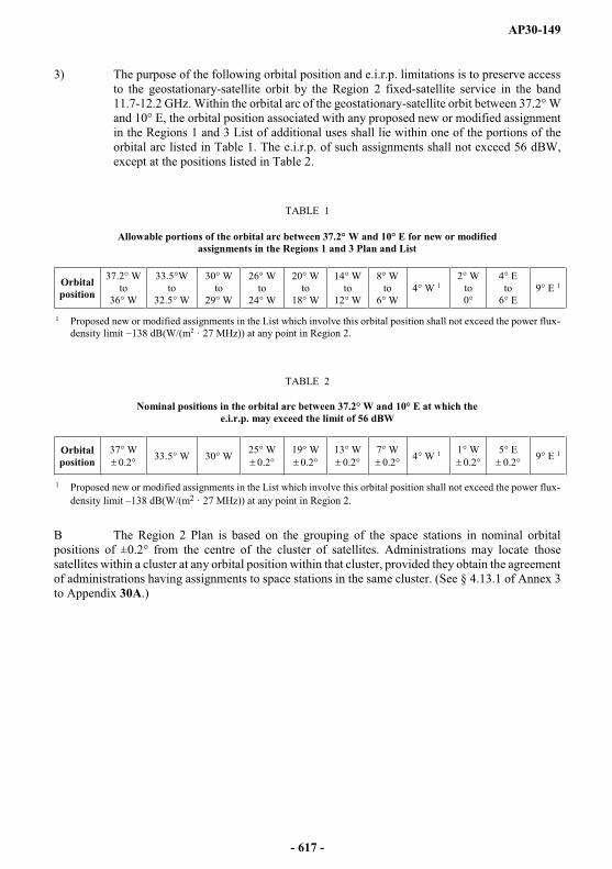
AP30-149
3) The purpose of the following orbital position and e.i.r.p. limitations is to preserve access to the geostationary-satellite orbit by the Region 2 fixed-satellite service in the band 11.7-12.2 GHz. Within the orbital arc of the geostationary-satellite orbit between 37.2° Wand 10° E, the orbital position associated with any proposed new or modified assignment in the Regions 1 and 3 List of additional uses shall lie within one of the portions of the orbital arc listed in Table 1. The e.i.r.p. of such assignments shall not exceed 56 dBW, except at the positions listed in Table 2.
TABLE 1
Allowable portions of the orbital arc between 37.2° W and 10° E for new or modified assignments in the Regions 1 and 3 Plan and List
Orbital position
37.2° Wto
36° W
33.5°Wto
32.5° W
30° Wto
29° W
26° Wto
24° W
20° Wto
18° W
14° Wto
12° W
8° Wto
6° W4° W 1
2° Wto0°
4° Eto
6° E9° E 1
1 Proposed new or modified assignments in the List which involve this orbital position shall not exceed the power flux-dB(W/(m2 · 27 MHz)) at any point in Region 2.
TABLE 2
Nominal positions in the orbital arc between 37.2° W and 10° E at which the e.i.r.p. may exceed the limit of 56 dBW
Orbital position
37° W0.2° 33.5° W 30° W 25° W
0.2°19° W
0.2°13° W
0.2°7° W
0.2° 4° W 1 1° W0.2°
5° E0.2° 9° E 1
1 Proposed new or modified assignments in the List which involve this orbital position shall not exceed the power flux-density limit 138 dB(W/(m2 · 27 MHz)) at any point in Region 2.
B The Region 2 Plan is based on the grouping of the space stations in nominal orbital positions of ±0.2° from the centre of the cluster of satellites. Administrations may locate those satellites within a cluster at any orbital position within that cluster, provided they obtain the agreement of administrations having assignments to space stations in the same cluster. (See § 4.13.1 of Annex 3 to Appendix 30A.)
- 617 -


AP30A-1
APPENDIX 30A (REV.WRC-15)*
Provisions and associated Plans and List1 for feeder links for the broadcasting-satellite service (11.7-12.5 GHz in Region 1, 12.2-12.7 GHz
in Region 2 and 11.7-12.2 GHz in Region 3) in the frequency bands 14.5-14.8 GHz2 and 17.3-18.1 GHz in Regions 1 and 3,
and 17.3-17.8 GHz in Region 2 (WRC-03)
(See Articles 9 and 11) (WRC-03)
TABLE OF CONTENTS
Page
Article 1 General definitions ........................................................................................... 3
Article 2 Frequency bands ............................................................................................... 4
Article 2A Use of the guardbands ...................................................................................... 4
Article 3 Execution of the provisions and associated Plans ............................................ 5
Article 4 Procedures for modifications to the Region 2 feeder-link Plan or for additional uses in Regions 1 and 3 ................................................................... 6
Article 5 Coordination, notification, examination and recording in the Master International Frequency Register of frequency assignments to feeder-link transmitting earth stations and receiving space stations in the fixed-satellite service ............................................................................................................... 18
Article 6 Coordination, notification and recording in the Master International Frequency Register of frequency assignments to receiving terrestrial stations in Regions 1 and 3 in the bands 14.5-14.8 GHz and 17.7-18.1 GHz, and in Region 2 in the band 17.7-17.8 GHz, when frequency assignments to feeder-link transmitting earth stations for the broadcasting-satellite service in conformity with the Regions 1 and 3 feeder-link Plan or the Region 2 feeder-link Plan are involved ....................................................................................... 24
_______________*to refer to a frequency assignment associated with a given orbital position. (WRC-03)
1 The Regions 1 and 3 feeder-link List of additional uses is annexed to the Master International Frequency Register (see Resolution 542 (WRC-2000)**). (WRC-03)
** Note by the Secretariat: This Resolution was abrogated by WRC-03.
2 This use of the band 14.5-14.8 GHz is reserved for countries outside Europe.
Note by the Secretariat: Reference to an Article with the number in roman is referring to an Article in this Appendix.
- 619 -

AP30A-2
Page
Article 7 Coordination, notification and recording in the Master International Frequency Register of frequency assignments to stations in the fixed-satellite service (space-to-Earth) in Region 1 in the band 17.3-18.1 GHz and in Regions 2 and 3 in the band 17.7-18.1 GHz, to stations in the fixed-satellite service (Earth-to-space) in Region 2 in the band 17.8-18.1 GHz and to stations in the broadcasting-satellite service in Region 2 in the band 17.3-17.8 GHz when frequency assignments to feeder links for broadcasting-satellite stations in the 17.3-18.1 GHz band in Regions 1 and 3 or in the band 17.3-17.8 GHz in Region 2 are involved .................................................................................. 25
Article 8 Miscellaneous provisions relating to the procedures ....................................... 28
Article 9 Plan for feeder links for the broadcasting-satellite service in the fixed-satellite service in the frequency band 17.3-17.8 GHz in Region 2 .............................. 29
Article 9A Plan for feeder links for the broadcasting-satellite service in the fixed-satellite service in the frequency bands 14.5-14.8 GHz and 17.3-18.1 GHz in Regions 1 and 3 ................................................................................................ 65
Article 10 Interference ....................................................................................................... 93
Article 11 Period of validity of the provisions and associated Plans ................................ 93
ANNEXES
Annex 1 Limits for determining whether a service of an administration is considered to be affected by a proposed modification to the Region 2 feeder-link Plan or by a proposed new or modified assignment in the Regions 1 and 3 feeder-link List or when it is necessary under this Appendix to seek the agreement of any other administration .......................................................................................... 93
Annex 2 Basic characteristics to be furnished in notices relating to feeder-link stations in the fixed-satellite service operating in the frequency bands 14.5-14.8 GHz and 17.3-18.1 GHz ........................................................................................... 96
Annex 3 Technical data used in establishing the provisions and associated Plans and Regions 1 and 3 feeder-link List, which should be used for their application ................................................................................................ 96
Annex 4 Criteria for sharing between services ............................................................... 136
- 620 -

AP30A-3
ARTICLE 1 (REV.WRC-03)
General definitions
1 For the purposes of this Appendix, the following terms shall have the meanings defined below:
1.1 Regions 1 and 3 feeder-link Plan: The Plan for feeder links in the frequency bands 14.5-14.8 GHz3 and 17.3-18.1 GHz for the broadcasting-satellite service in Regions 1 and 3contained in this Appendix.
1.2 Region 2 feeder-link Plan: The Plan for feeder links in the frequency band 17.3-17.8 GHz for the broadcasting-satellite service in Region 2 contained in this Appendix, together with any modifications resulting from the successful application of the procedure of Article 4.
1.3 Frequency assignment in conformity with the Plan:
any frequency assignment for a receiving space station or transmitting earth station which appears in the Regions 1 and 3 feeder-link Plan; or
any frequency assignment for a receiving space station or transmitting earth station which appears in the Region 2 feeder-link Plan or for which the procedure of Article 4 has been successfully applied.
1.4 1983 Conference: Regional Administrative Radio Conference for the Planning in Region 2 of the Broadcasting-Satellite Service in the Frequency Band 12.2-12.7 GHz and Associated Feeder-links in the Frequency Band 17.3-17.8 GHz, called in short Regional Administrative Conference for the Planning of the Broadcasting-Satellite Service in Region 2 (Geneva, 1983) (RARC Sat-R2).
1.5 1985 Conference: First Session of the World Administrative Radio Conference on the Use of the Geostationary-Satellite Orbit and the Planning of Space Services Utilizing It (Geneva, 1985), called in short WARC Orb-85.
1.6 1988 Conference: Second Session of the World Administrative Radio Conference on the Use of the Geostationary-Satellite Orbit and the Planning of Space Services Utilizing It (Geneva, 1988), called in short WARC Orb-88.
1.7 1997 Conference: World Radiocommunication Conference (Geneva, 1997), called in short WRC-97.
1.8 2000 Conference: World Radiocommunication Conference (Istanbul, 2000), called in short WRC-2000.
_______________3 This use of the band 14.5-14.8 GHz is reserved for countries outside Europe.
- 621 -
AP30A-4
1.9 Additional use in Regions 1 and 3: For the application of the provisions of this Appendix, additional uses in Regions 1 and 3 are:
a) use of assignments with characteristics different from those appearing in the Regions 1 and 3 feeder-link Plan and which are capable of causing more interference than the corresponding entries in that Plan;
b) use of assignments in addition to those appearing in the Regions 1 and 3 feeder-link Plan.
1.10 Regions 1 and 3 feeder- -: The list of assignments for additional uses in Regions 1 and 3 as established by WRC-2000
(see Resolution 542 (WRC-2000)*), as updated following the successful application of the procedure of § 4.1 of Article 4. (WRC-03)
1.11 Frequency assignment in conformity with the feeder-link List: Any frequency assignment which appears in the feeder-link List as updated following successful application of § 4.1 of Article 4. (WRC-03)
1.12 Broadcasting-satellite service (BSS) feeder link subject to one of the Plans: The BSS feeder-link subject to one of the Plans referred to in this Appendix is the BSS feeder link in the frequency bands 14.5-14.8 GHz and 17.3-18.1 GHz in Regions 1 and 3 and 17.3-17.8 GHz in Region 2. (WRC-03)
ARTICLE 2 (WRC-03)
Frequency bands
2.1 The provisions of this Appendix apply to the feeder-links in the fixed-satellite service (Earth-to-space) in the frequency bands 14.5-14.8 GHz and 17.3-18.1 GHz for the broadcasting-satellite service in Regions 1 and 3, and 17.3-17.z8 GHz for the broadcasting-satellite service in Region 2 and to other services to which these bands are allocated in Regions 1, 2 and 3 so far as their relationship to the fixed-satellite service (Earth-to-space) in these bands is concerned.
2.2 (SUP - WRC-03)
ARTICLE 2A (REV.WRC-15)
Use of the guardbands
2A.1 The use of the guardbands defined in § 3.1 and 4.1 of Annex 3 to provide space operation functions in accordance with No. 1.23 in support of the operation of geostationary-satellite networks for the broadcasting-satellite service (BSS) feeder link is not subject to the application of Section I of Article 9.
_______________* Note by the Secretariat: This Resolution was abrogated by WRC-03.
- 622 -

AP30A-5
2A.1.1 Coordination between assignments intended to provide the space operation functions and assignments of the BSS feeder link subject to a Plan shall be effected using the provisions of Article 7.
2A.1.2 Coordination among assignments intended to provide the space operation functions and services not subject to a Plan shall be effected using the provisions of Nos. 9.7, 9.17, 9.17A, 9.18, and the associated provisions of Section II of Article 9, as appropriate.
2A.1.3 Coordination of modifications to the Region 2 feeder-link Plan or assignments to be included in the Regions 1 and 3 feeder-link List, with assignments intended to provide these functions shall be effected using § 4.1.1 d) of Article 4.
2A.1.4 Requests for the coordination referred to in § 2A.1.1, 2A.1.2 and 2A.1.3 shall be sent by the requesting administration to the Bureau, together with the appropriate information listed in Appendix 4.
2A.2 Any assignment intended to provide these functions in support of a geostationary-satellite network for the BSS feeder link shall be notified under Article 11 and brought into use within the following time-limits3bis: (WRC-15)
2A.2.1 a) for the case where the associated BSS feeder-link assignments are contained in one of the initial Plans (Region 2 Plans incorporated in the Radio Regulations at WARC Orb-85 and Regions 1 and 3 Plan adopted at WRC-2000), within the regulatory time-limit referred to in § 4.1.3 or 4.2.6 of Article 4 from the date of receipt by the Bureau of the complete Appendix 4 data for those assignments intended to provide the space operation functions;
2A.2.2 b) for the case where the associated BSS feeder-link assignments have been submitted under § 4.1.3 or § 4.2.6 of Article 4 for entry in the Regions 1 and 3 List or a modification to the Region 2 Plan, within the regulatory time-limit referred to in § 4.1.3 or § 4.2.6 of Article 4 for those associated BSS feeder-link assignments;
2A.2.3 c) for the case where the associated BSS feeder-link assignments have already been brought into use in accordance with the Radio Regulations, within the regulatory time-limit referred to in § 4.1.3 and § 4.2.6 of Article 4 from the date of receipt by the Bureau of the complete Appendix 4data for those assignments intended to provide these space operation functions.
ARTICLE 3 (REV.WRC-03)
Execution of the provisions and associated Plans
3.1 The Member States in Regions 1, 2 and 3 shall adopt, for their feeder-link space and earth stations in the fixed-satellite service (Earth-to-space) in the frequency bands referred to in this Appendix, the characteristics specified in the appropriate Regional Plan and the associated provisions.
_______________3bis The time-limit is established at the time when the request is received under § 2A.1.4. (WRC-15)
- 623 -

AP30A-6
3.2 The Member States shall not change the characteristics specified in the Region 1 and 3feeder-link Plan or in the Region 2 feeder-link Plan, or bring into use assignments to receiving space stations or transmitting earth stations in the fixed-satellite service or to stations of the other services to which these frequency bands are allocated, except as provided for in the Radio Regulations and the appropriate Articles and Annexes of this Appendix.
3.3 The procedures for the use of interim systems in Region 2 for feeder links in the fixed-satellite service for the bands covered by this Appendix are given in Resolution 42(Rev.WRC-03)*. (WRC-03)
3.4 The Regions 1 and 3 feeder-link Plan is based on national coverage from the geostationary-satellite orbit. The associated procedures contained in this Appendix are intended to promote long-term flexibility of the Plan and to avoid monopolization of the planned bands and orbit by a country or a group of countries.
ARTICLE 4 (REV.WRC-15)
Procedures for modifications to the Region 2 feeder-link Plan or for additional uses in Regions 1 and 3
4.1 Provisions applicable to Regions 1 and 3
4.1.1 An administration proposing to include a new or modified assignment in the feeder-link List shall seek the agreement of those administrations whose services are considered to be affected, i.e. administrations4, 5:
a) of Regions 1 and 3 having a feeder-link frequency assignment in the fixed-satellite service (Earth-to-space) to a space station in the broadcasting-satellite service which is included in the Regions 1 and 3 feeder-link Plan with a necessary bandwidth, any portion of which falls within the necessary bandwidth of the proposed assignment; or
b) of Regions 1 and 3 having a feeder-link frequency assignment included in the feeder-link List or for which complete Appendix 4 information has been received by the Radiocommunication Bureau in accordance with the provisions of § 4.1.3, and any portion of which falls within the necessary bandwidth of the proposed assignment; or
_______________* Note by the Secretariat: This Resolution was revised by WRC-12 and WRC-15.
4 Agreement with administrations having a frequency assignment in the bands 14.5-14.8 GHz or 17.7-18.1 GHz to a terrestrial station, or having a frequency assignment in the band 17.7-18.1 GHz to an earth station in the fixed-satellite service (space-to-Earth), or having a frequency assignment in the band 17.3-17.8 GHz in the broadcasting-satellite service shall be sought under No. 9.17, No. 9.17A or No. 9.19, respectively.
5 Coordination under Nos. 9.17 or 9.17A is not required for an earth station of an administration on the territory of which this earth station is located and for which the procedures of former § 4.2.1.2 and 4.2.1.3 of Appendix 30A(WRC-97) have been successfully applied by that administration before 3 June 2000 in respect of terrestrial stations or earth stations operating in the opposite direction of transmission. (WRC-03)
- 624 -

AP30A-7
c) of Region 2 having a feeder-link frequency assignment in the fixed-satellite service (Earth-to-space) to a space station in the broadcasting-satellite service which is in conformity with the Region 2 feeder-link Plan, or in respect of which proposed modifications to that Plan have already been received by the Bureau in accordance with the provisions of § 4.2.6 with a necessary bandwidth, any portion of which falls within the necessary bandwidth of the proposed assignment; or
d) having a feeder-link frequency assignment in the frequency band 17.8-18.1 GHz in Region 2 in the fixed-satellite service (Earth-to-space) to a space station in the broadcasting-satellite service, or a frequency assignment in the frequency band 14.5-14.75 GHz in countries listed in Resolution 163 (WRC-15) and in the frequency band 14.5-14.8 GHz in countries listed in Resolution 164 (WRC-15), in the fixed-satellite service (Earth-to-space) not subject to a Plan, which is recorded in the Master Register or which has been coordinated or is being coordinated under the provisions of No. 9.7, or under § 7.1 of Article 7, with a necessary bandwidth, any portion of which falls within the necessary bandwidth of the proposed assignment. (WRC-15)
4.1.2 The services of an administration are considered to be affected when the limits shown in Annex 1 are exceeded.
4.1.3 An administration, or one6 acting on behalf of a group of named administrations, intending to include a new or modified assignment in the feeder-link List shall send to the Bureau, not earlier than eight years but preferably not later than two years before the date on which the assignment is to be brought into use, the relevant information listed in Appendix 4. An assignment in the feeder-link List shall lapse if it is not brought into use within eight years after the date of receipt by the Bureau of the relevant complete information. A proposed new or modified assignment not included in the List within eight years after the date of receipt by the Bureau of the relevant complete information7 shall also lapse. (WRC-07)
4.1.3bis The regulatory time-limit for bringing into use an assignment in the List may be extended once by not more than three years due to launch failure in the following cases:
the destruction of the satellite intended to bring the assignment into use; or
the destruction of the satellite launched to replace an already operating satellite which is intended to be relocated to bring another assignment into use; or
the satellite is launched, but fails to reach its assigned orbital location.
_______________6 Whenever, under this provision, an administration acts on behalf of a group of named administrations, all members of that group retain the right to respond in respect of their own networds or systems. (WRC-03)
7 The provisions of Resolution 533 (Rev.WRC-2000)* apply. (WRC-03)
* Note by the Secretariat: This Resolution was abrogated by WRC-12.
- 625 -

AP30A-8
For this extension to be granted, the launch failure must have occurred at least five years after the date of receipt of the complete Appendix 4 data. In no case shall the period of the extension of the regulatory time-limit exceed the difference in time between the three-year period and the period remaining from the date of the launch failure to the end of the regulatory time-limit8. In order to take advantage of this extension, the administration shall have, within one month of the launch failure orone month after 5 July 2003, whichever comes later, notified the Bureau in writing of such failure, and shall also provide the following information to the Bureau before the end of the regulatory time-limit of § 4.1.3:
date of launch failure;
due diligence information as required in Resolution 49 (Rev.WRC-15) for the assignment with respect to the satellite that suffered the launch failure, if that information has not already been provided.
If, 11 months after the request for extension, the administration has not provided to the Bureau updated Resolution 49 (Rev.WRC-15) information, the Bureau shall promptly send a reminder to the notifying administration. If, within one year of the request for extension, the administration has not provided to the Bureau updated Resolution 49 (Rev.WRC-15) information for the new satellite under procurement, the related frequency assignments shall lapse. (WRC-15)
4.1.4 If the information received by the Bureau under § 4.1.3 is found to be incomplete, the Bureau shall immediately seek from the administration concerned any clarification required and information not provided.
4.1.5 The Bureau shall determine, on the basis of Annex 1, the administrations whose frequency assignments are considered to be affected. The Bureau shall publish9, in a Special Section of itsInternational Frequency Information Circular (BR IFIC), the complete information received under § 4.1.3, together with the names of the affected administrations, the corresponding fixed-satellite service networks, and the corresponding feeder-links to broadcasting-satellite service assignments, as appropriate. The Bureau shall immediately send a telegram/fax to the administration proposing the assignment, drawing its attention to the information contained in the relevant BR IFIC. (WRC-07)
4.1.6 The Bureau shall send a telegram/fax to the administrations listed in the Special Section of the BR IFIC, drawing their attention to the information it contains. (WRC-07)
4.1.7 An administration which considers that it should have been identified in the publication referred to under § 4.1.5 above shall, within four months of the date of publication of its relevant BR IFIC, and giving the technical reasons for so doing, request the Bureau to include its name in the publication. The Bureau shall study this information on the basis of Annex 1 and shall inform both administrations of its conclusions. Should the Bureau agree to the administration's request, it shall publish an addendum to the publication under § 4.1.5.
_______________8 For a launch failure which occurred before 5 July 2003, the maximum extension of three years shall apply as from 5 July 2003. (WRC-03)
9 If the payments are not received in accordance with the provisions of Council Decision 482, as amended, on the implementation of cost recovery for satellite network filings, the Bureau shall cancel the publication, after informing the administration concerned. The Bureau shall inform all administrations of such action and that the network specified in the publication in question no longer has to be taken into consideration by the Bureau and other administrations. The Bureau shall send a reminder to the notifying administration not later than two months prior to the deadline for the payment in accordance with the above-mentioned Council Decision 482 unless the payment has already been received. (WRC-07)
- 626 -
AP30A-9
4.1.7bis Except as provided under § 4.1.18 to 4.1.20, any inclusion of a new or modified frequency assignment in the Regions 1 and 3 List which would have the effect of exceeding the limits specified in Annex 1 shall be subject to the agreement of all administrations whose services are considered to be affected. (WRC-03)
4.1.8 The administration seeking agreement or the administration with which agreement is sought may request any additional technical information it considers necessary. The administrations shall inform the Bureau of such requests.
4.1.9 Comments from administrations identified in the publication referred to under § 4.1.5 above shall be sent to the Bureau and to the administration proposing the modification. (WRC-15)
4.1.10 An administration that has not notified its agreement either to the administration seeking agreement or to the Bureau within a period of four months following the date of the BR IFIC referred to in § 4.1.5 shall be deemed to have not agreed to the proposed assignment unless the provisions of § 4.1.10a to 4.1.10d and § 4.1.21 are applied. This time-limit may be extended:
for an administration that has requested additional information under § 4.1.8, by up to three months, or
for an administration that has requested the assistance of the Bureau under § 4.1.21, by up to three months following the date at which the Bureau communicated the result of its action. (WRC-15)
4.1.10bis Thirty days prior to the expiry of the same four-month period, the Bureau shall dispatch a reminder telegram or fax to an administration which has not made its comments under § 4.1.10, bringing the matter to its attention. (WRC-03)
4.1.10ter (SUP - WRC-15)
4.1.10a After the same time period as specified in § 4.1.10, the notifying administration may, pursuant to § 4.1.21, request the Bureau to assist in respect of an administration which has not replied within this time period. (WRC-15)
4.1.10b The Bureau, acting under § 4.1.10a, shall send a reminder to the administration which has not replied, together with the results of its previously published compatibility analysis, containing the change in the values referred to in paragraph 4 of Annex 1 to Appendix 30A, requesting a decision. (WRC-15)
4.1.10c Fifteen days before the expiry of the 30-day period referred to in § 4.1.10d, the Bureau shall send a reminder to the above-mentioned administration drawing its attention to the consequence of no reply. (WRC-15)
4.1.10d If no decision is communicated to the Bureau within 30 days after the date of dispatch of the reminder under § 4.1.10b, it shall be deemed that the administration which has not given a decision has agreed to the proposed assignment. (WRC-15)
4.1.11 If, in seeking agreement, an administration modifies its initial proposal, it shall again apply the provisions of § 4.1 and the subsequent procedure in cases where:
the assignments of any other administration received by the Bureau in accordance with § 4.1.3 or § 4.2.6, or § 2A.1.4 of Article 2A, or § 7.1 of Article 7, or No. 9.7 before this modified proposal is received under § 4.1.12; or
the assignments of any other administration contained in the Plans or the Lists,
are considered as being affected and receive more interference as a result of the modifications than that produced by the initial proposal. (WRC-15)
- 627 -
AP30A-10
4.1.12 If agreement has been reached with the administrations identified in the publication referred to under § 4.1.5 above, the administration proposing the new or modified assignment may continue with the appropriate procedure in Article 5 and shall inform the Bureau, indicating the final characteristics of the frequency assignment together with the names of the administrations with which agreement has been reached. (WRC-15)
4.1.12bis In application of § 4.1.12, an administration may indicate the changes to the information communicated to the Bureau under § 4.1.3 and published under § 4.1.5. (WRC-03)
4.1.13 The agreement of the administrations affected may also be obtained in accordance with this Article, for a specified period. When this specific period of agreement expires for an assignment in the List, the assignment in question shall be maintained in the List until the end of the period referred to in § 4.1.3 above. After that date this assignment shall lapse unless the agreement of the administrations affected is renewed. (WRC-03)
4.1.14 Where the proposed assignment involves developing countries, administrations shall seek all practicable solutions conducive to the economical development of the broadcasting-satellite systems of these countries.
4.1.15 The Bureau shall publish10 in a Special Section of its BR IFIC the information received under § 4.1.12, together with the names of any administrations with which the provisions of this Article have been successfully applied. The frequency assignment concerned shall be included in the feeder-link List. (WRC-03)
4.1.16 In case of disagreement on the part of an administration whose agreement has been sought, the requesting administration should first endeavour to solve the problem by exploring all possible means of meeting its requirement. If the problem still cannot be solved by such means, the administration whose agreement has been sought should endeavour to overcome the difficulties as far as possible, and shall state the technical reasons for any disagreement if the administration seeking the agreement requests it to do so.
4.1.17 If no agreement is reached between the administrations concerned, the Bureau shall carry out any study that may be requested by either one of these administrations; the Bureau shall inform them of the result of the study and shall make such recommendations as it may be able to offer for the solution of the problem.
_______________10 If the payments are not received in accordance with the provisions of Council Decision 482, as amended, on the implementation of cost recovery for satellite network filings, the Bureau shall cancel the publication, after informing the administration concerned. The Bureau shall inform all administrations of such action and that the network specified in the publication in question no longer has to be taken into consideration by the Bureau and other administrations. The Bureau shall send a reminder to the notifying administration not later than two months prior to the deadline for the payment in accordance with the above-mentioned Council Decision 482 unless the payment has already been received. (WRC-07)
- 628 -
AP30A-11
4.1.18 If, in spite of the application of § 4.1.16 and 4.1.17, there is still continuing disagreement and the assignment which was the basis of the disagreement is not an assignment in the Regions 1and 3 Plan, or in the Region 2 Plan or for which the procedure of § 4.2 has been initiated, and if the notifying administration insists that the proposed assignment be included in the Regions 1 and 3 feeder-link List, the Bureau shall provisionally enter the assignment in the Regions 1 and 3 feeder-link List with an indication of those administrations whose assignments were the basis of the disagreement; however, the entry shall be changed from provisional to definitive recording in the feeder-link List only if the Bureau is informed that the new assignment in the Regions 1 and 3 feeder-link List has been in use, together with the assignment which was the basis for the disagreement, for at least four months without any complaint of harmful interference being made. (WRC-03)
4.1.18bis When requesting the application of § 4.1.18, the notifying administration shall undertake to meet the requirements of § 4.1.20 and provide to the administration in respect of which § 4.1.18 is applied, with a copy to the Bureau, a description of the steps by which it undertakes to meet these requirements. Once an assignment is entered in the feeder-link List provisionally under the provisions of § 4.1.18, the calculation of the equivalent protection margin (EPM)11 of an assignment in the Regions 1 and 3 feeder-link List or for which the procedure of Article 4 has been initiated and which was the basis for the disagreement shall not take into account interference produced by the assignment for which the provisions of § 4.1.18 have been applied. (WRC-03)
4.1.19 Should the assignments that were the basis of the disagreement not be brought into use within the period specified in No. 11.44 (for non-planned services), or in § 4.1 (for assignments in the feeder-link List or having initiated the procedure under § 4.1), as appropriate, then the status of the assignment in the feeder-link List shall be reviewed accordingly. (WRC-03)
4.1.20 Should harmful interference be caused by an assignment included in the feeder-link List under § 4.1.18 to any recorded assignment in the Master Register which was the basis of the disagreement, the administration using the frequency assignment included in the feeder-link List under § 4.1.18 shall, upon receipt of advice thereof, immediately eliminate this harmful interference. (WRC-03)
4.1.21 An administration may, at any stage in the procedure described, or before applying it, request the assistance of the Bureau.
4.1.22 The relevant provisions of Article 5 shall be applied when frequency assignments are notified to the Bureau.
4.1.23 When a frequency assignment included in the feeder-link List is no longer required, the administration concerned shall immediately so inform the Bureau. The Bureau shall publish this information in a Special Section of its BR IFIC and delete the assignment from the feeder-link List. (WRC-03)
_______________11 For the definition of the EPM, see § 1.7 of Annex 3. (WRC-03)
- 629 -
AP30A-12
4.1.24 No assignment in the feeder-link List shall have a period of operation exceeding 15 years, counted from the date of bringing into use, or 2 June 2000, whichever is later. Upon request by the responsible administration received by the Bureau at the latest three years before the expiry of this period, this period may be extended by up to 15 years, on condition that all the characteristics of the assignment remain unchanged. (WRC-03)
4.1.25 Where an administration already having included in the feeder-link List two assignments (not including those systems notified on behalf of a group of named administrations and included in the feeder-link List by WRC-2000) in the same channel and covering the same service area, proposes to include in the feeder-link List a new assignment in the same channel over this same service area, it shall apply the following in respect of another administration which has no assignment in the feeder-link List in the same channel and which proposes to include in the feeder-link List a new assignment:
a) if the agreement of the former administration is required following the application of § 4.1 by the latter administration, in order to protect the new assignment proposed by the former administration from interference caused by the assignment proposed by the latter administration, both administrations shall make every possible effort to resolve the difficulties by means of mutually acceptable adjustments to their networks;
b) in case of continuing disagreement, and if the former administration has not communicated to the Bureau the information specified in Annex 2 to Resolution 49 (Rev.WRC-15), this administration shall be deemed to have given its agreement to inclusion in the feeder-link List of the assignment of the latter administration. (WRC-15)
4.1.26 The procedure of this Article may be applied by the administration of a new ITU Member State in order to include new assignments in the feeder-link List. Upon completion of the procedure, the next world radiocommunication conference may be requested to consider, among the assignments included in the feeder-link List after the successful completion of this procedure, the inclusion in the Regions 1 and 3 feeder-link Plan of up to 10 channels (for Region 1) and up to 12 channels (for Region 3), over the national territory of the new Member State. (WRC-03)
4.1.27 When an administration has successfully applied this procedure and received all the agreements12 required to include in the feeder-link List assignments over its national territory, at an orbital location and/or in channels different from those appearing in the Regions 1 and 3 feeder-link Plan for its country, it may request the next world radiocommunication conference to consider the inclusion in this Plan of up to 10 (for Region 1) and up to 12 (for Region 3) of these assignments, in replacement of its assignments appearing in this Plan. (WRC-03)
4.1.27bis Should the assignments mentioned in § 4.1.26 and 4.1.27 over the national territory of the administration not be brought into use within the regulatory time-limit mentioned in § 4.1.3, they would be retained in the List until the end of the World Radiocommunication Conference following immediately after the successful completion of procedure referred to in § 4.1.26 and 4.1.27, respectively and thereafter they shall be removed from the List. (WRC-03)
_______________12 In such a case, § 4.1.18 does not apply.
- 630 -
AP30A-13
4.1.28 The feeder-link List, as updated, shall be published periodically by the Bureau. (WRC-03)
4.1.29 New or modified assignments in the feeder-link List shall be limited to digital modulation. (WRC-03)
4.2 Provisions applicable to Region 2
4.2.1 When an administration intends to make a modification to the Region 2 feeder-link Plan, i.e.:
a) to modify the characteristics of any of its frequency assignments in the fixed-satellite service which are shown in the Region 2 feeder-link Plan, or for which the procedure in this Article has been successfully applied, whether or not the station has been brought into use; or
b) to include in the Region 2 feeder-link Plan a new frequency assignment in the fixed-satellite service; or
c) to cancel a frequency assignment in the fixed-satellite service,
the following procedure shall be applied before any notification of the frequency assignment is made to the Bureau (see Article 5 and Resolution 42 (Rev.WRC-03)*). (WRC-03)
4.2.2 An administration proposing a modification to the characteristics of a frequency assignment in conformity with the Region 2 feeder-link Plan, or the inclusion of a new frequency assignment in that Plan, shall seek the agreement of those administrations13, 14, 15:
a) having an assignment for feeder-links in the fixed-satellite service (Earth-to-space) which is in conformity with the Regions 1 and 3 feeder-link Plan with the necessary bandwidth, any portion of which falls within the necessary bandwidth of the proposed assignment; or
b) of Regions 1 and 3 having a feeder-link frequency assignment included in the feeder-link List or for which complete Appendix 4 information has been received by the Bureau in accordance with the provisions of § 4.1.3, and any portion of which falls within the necessary bandwidth of the proposed assignment; or
c) of Region 2 having a feeder-link frequency assignment in the fixed-satellite service (Earth-to-space) in the same channel or an adjacent channel, which appears in the Region 2 feeder-link Plan or in respect of which proposed modifications to this Plan have been received by the Bureau in accordance with the provisions of § 4.2.6;
d) which are considered affected. (WRC-03)
_______________* Note by the Secretariat: This Resolution was revised by WRC-12 and WRC-15.
13 Agreement with administrations having a frequency assignment in the bands 17.7-17.8 GHz to a terrestrial station or to an earth station in the fixed-satellite service (space-to-Earth) shall be sought under No. 9.17 or No. 9.17A, respectively.
14 Coordination under No. 9.17 or 9.17A is not required for an earth station of an administration on the territory of which this earth station is located and for which the procedures of former § 4.2.3.2 and 4.2.3.3 of Appendix 30A (WRC-97)have been successfully applied by that administration before 3 June 2000 in respect of terrestrial stations or earth stations operating in the opposite direction of transmission. (WRC-03)
15 Agreement with administrations having a frequency assignment in the band 17.3-17.8 GHz to an earth station in the broadcasting-satellite service shall be sought under No. 9.19.
- 631 -
AP30A-14
4.2.3 (Not used.)
4.2.4 The services of an administration are considered to be affected when the limits shown in Annex 1 are exceeded.
4.2.5 The agreement referred to in § 4.2.2 is not required when an administration proposes to bring into use, with characteristics appearing in the Region 2 feeder-link Plan, a fixed feeder-link earth station in the band 17.3-17.8 GHz or a transportable feeder-link earth station in the band 17.3-17.7 GHz. Administrations may communicate to the Bureau the characteristics of such earth stations for inclusion in this Plan.
4.2.6 An administration, or one16 acting on behalf of a group of named administrations, intending to make a modification to the Region 2 feeder-link Plan shall send to the Bureau, not earlier than eight years but preferably not later than two years before the date on which the assignment is to be brought into use, the relevant information listed in Appendix 4. Modifications to that Plan shall lapse if the assignment is not brought into use within eight years after the date of receipt by the Bureau of the relevant complete information17. A request for a modification that has not been included in that Plan within eight years after the date of receipt by the Bureau of the relevant complete information17
shall also lapse. (WRC-07)
4.2.6bis The regulatory time-limit for bringing into use of an assignment in the Region 2 Plan obtained through application of § 4.2 may be extended once by no more than three years due to launch failure in the following cases:
the destruction of the satellite intended to bring the assignment into use; or
the destruction of the satellite launched to replace an already operating satellite which is intended to be relocated to bring another assignment into use; or
the satellite is launched, but fails to reach its assigned orbital location.
For this extension to be granted, the launch failure must have occurred at least five years after the date of receipt of the complete Appendix 4 data. In no case shall the period of the extension of the regulatory time-limit exceed the difference in time between the three-year period and the period remaining from the date of the launch failure to the end of the regulatory time-limit18. In order to take advantage of this extension, the administration shall have, within one month of the launch failure orone month after 5 July 2003, whichever comes later, notified the Bureau in writing of such failure, and shall also provide the following information to the Bureau before the end of the regulatory time-limit of § 4.2.6:
date of launch failure;
due diligence information as required in Resolution 49 (Rev.WRC-15) for the assignment with respect to the satellite that suffered the launch failure, if that information has not already been provided.
_______________16 Whenever, under this provision, an administration acts on behalf of a group of named administrations, all members of that group retain the right to respond in respect of their own networks or systems. (WRC-03)
17 The provisions of Resolution 533 (Rev.WRC-2000)* apply. (WRC-03)
* Note by the Secretariat: This Resolution was abrogated by WRC-12.
18 For a launch failure which occurred before 5 July 2003, the maximum extension of three years shall apply as from 5 July 2003. (WRC-03)
- 632 -
AP30A-15
If, 11 months after the request for extension, the administration has not provided to the Bureau updated Resolution 49 (Rev.WRC-15) information, the Bureau shall promptly send a reminder to the notifying administration. If, within one year of the request for extension, the administration has not provided to the Bureau updated Resolution 49 (Rev.WRC-15) information for the new satellite under procurement, the related frequency assignments shall lapse. (WRC-15)
4.2.7 If the information received by the Bureau under § 4.2.6 is found to be incomplete, the Bureau shall immediately seek from the administration concerned any clarification required and information not provided.
4.2.8 The Bureau shall determine, on the basis of Annex 1, the administrations whose frequency assignments are considered to be affected within the meaning of § 4.2.2. The Bureau shall publish19,in a Special Section of its BR IFIC, the complete information received under § 4.2.6, together with the names of the affected administrations, the corresponding fixed-satellite service networks, and the corresponding feeder links to broadcasting-satellite service assignments, as appropriate. The Bureau shall immediately send a telegram/fax to the administration proposing the modification to the Region 2 feeder-link Plan, drawing its attention to the information contained in the relevant BR IFIC. (WRC-07)
4.2.9 The Bureau shall send a telegram/fax to the administrations listed in the Special Section of its BR IFIC, drawing their attention to the information it contains. (WRC-07)
4.2.10 An administration which considers that it should have been included in the publication referred to under § 4.2.8 above shall, within four months of the date of publication in the relevant BR IFIC, and giving the technical reasons for so doing, request the Bureau to include its name in the publication. The Bureau shall study this information on the basis of Annex 1 and shall inform both administrations of its conclusions. Should the Bureau agree to the admipublish an addendum to the publication under § 4.2.8. (WRC-07)
4.2.11 Except as provided under § 4.2.21A to 4.2.21D, any modification to a frequency assignment which is in conformity with the Region 2 feeder-link Plan or any inclusion in that Plan of a new frequency assignment which would have the effect of exceeding the limits specified in Annex 1shall be subject to the agreement of all affected administrations. (WRC-03)
4.2.12 The administration seeking agreement or the administration with which agreement is sought may request any additional technical information it considers necessary. The administrations shall inform the Bureau of such requests.
4.2.13 Comments from administrations on the information published pursuant to § 4.2.8 should be sent either directly to the administration proposing the modification or through the Bureau. In any event, the Bureau shall be informed that comments have been made.
_______________19 If the payments are not received in accordance with the provisions of Council Decision 482, as amended, on the implementation of cost recovery for satellite network filings, the Bureau shall cancel the publication, after informing the administration concerned. The Bureau shall inform all administrations of such action and that the network specified in the publication in question no longer has to be taken into consideration by the Bureau and other administrations. The Bureau shall send a reminder to the notifying administration not later than two months prior to the deadline for the payment in accordance with the above-mentioned Council Decision 482 unless the payment has already been received. (WRC-07)
- 633 -

AP30A-16
4.2.14 An administration which has not notified its comments either to the administration seeking agreement or to the Bureau within a period of four months following the date of the BR IFIC referred to in § 4.2.8 shall be deemed to have agreed to the proposed modification. This time-limitmay be extended by up to three months for an administration which has requested additional information under § 4.2.12 or for an administration which has requested the assistance of the Bureau under § 4.2.22. In the latter case, the Bureau shall inform the administrations concerned of this request.
4.2.14bis Thirty days prior to the expiry of the same four-month period the Bureau shall dispatch a reminder telegram or fax to an administration which has not made its comments under § 4.2.14, bringing the matter to its attention. (WRC-03)
4.2.14ter After expiry of the deadline for comments in respect of the proposed assignment, the Bureau shall, according to its records, publish a Special Section, indicating the list of administrations whose agreements are required for completion of the procedure of Article 4. (WRC-03)
4.2.15 If, in seeking agreement, an administration modifies its initial proposal, it shall again apply the provisions of § 4.2 and the consequent procedure with respect to any other administration whose services might be affected as a result of modifications to the initial proposal.
4.2.16 If no comments have been received on the expiry of the periods specified in § 4.2.14, or if agreement has been reached with the administrations which have made comments and with which agreement is necessary, the administration proposing the modification may continue with the appropriate procedure in Article 5, and shall so inform the Bureau, indicating the final characteristics of the frequency assignment together with the names of the administrations with which agreement has been reached.
4.2.16bis In application of § 4.2.16, an administration may indicate the changes to the information communicated to the Bureau under § 4.2.6 and published under § 4.2.8. (WRC-03)
4.2.17 The agreement of the administrations affected may also be obtained in accordance with this Article, for a specified period. When this specific period of agreement expires for an assignment in the Plan, the assignment in question shall be maintained in the Plan until the end of the period referred to in § 4.2.6 above. After that date this assignment in the Plan shall lapse unless the agreement of the administrations affected is renewed. (WRC-03)
4.2.18 When the proposed modification to the Region 2 feeder-link Plan involves developing countries, administrations shall seek all practicable solutions conducive to the economical development of the broadcasting-satellite systems of these countries.
4.2.19 The Bureau shall publish20 in a Special Section of its BR IFIC the information received under § 4.2.16 together with the names of any administrations with which the provisions of this Article have been successfully applied. The frequency assignment concerned shall enjoy the same status as those appearing in the Region 2 feeder-link Plan and will be considered as a frequency assignment in conformity with that Plan. (WRC-03)
_______________20 If the payments are not received in accordance with the provisions of Council Decision 482, as amended, on the implementation of cost recovery for satellite network filings, the Bureau shall cancel the publication, after informing the administration concerned. The Bureau shall inform all administrations of such action and that the network specified in the publication in question no longer has to be taken into consideration by the Bureau and other administrations. The Bureau shall send a reminder to the notifying administration not later than two months prior to the deadline for the payment in accordance with the above-mentioned Council Decision 482 unless the payment has already been received. (WRC-07)
- 634 -

AP30A-17
4.2.20 When an administration proposing to modify the characteristics of a frequency assignment or to make a new frequency assignment receives notice of disagreement on the part of an administration whose agreement it has sought, it should first endeavour to solve the problem by exploring all possible means of meeting its requirement. If the problem still cannot be solved by such means, the administration whose agreement has been sought should endeavour to overcome the difficulties as far as possible, and shall state the technical reasons for any disagreement if the administration seeking the agreement requests it to do so.
4.2.21 If no agreement is reached between the administrations concerned, the Bureau shall carry out any study that may be requested by these administrations; the Bureau shall inform them of the result of the study and shall make such recommendations as it may be able to offer for the solution of the problem.
4.2.21A If, in spite of the application of § 4.2.20 and 4.2.21, there is still continuing disagreement and the assignment which was the basis of the disagreement is not an assignment in the Region 2 feeder-link Plan, or in the Regions 1 and 3 feeder-link Plan or List, or for which the procedure of § 4.1 or 4.2 has been initiated, and if the notifying administration insists that the proposed assignment be included in the Region 2 feeder-link Plan, the Bureau shall provisionally enter the assignment in the Region 2 feeder-link Plan with an indication of those administrations whose assignments were the basis of the disagreement; however, the entry shall be changed from provisional to definitive recording in the Region 2 feeder-link Plan only if the Bureau is informed that the new or modified assignment in the Region 2 feeder-link Plan has been in use, together with the assignment which was the basis for the disagreement, for at least four months without any complaint of harmful interference being made. (WRC-03)
4.2.21B When requesting the application of § 4.2.21A, the notifying administration shall undertake to meet the requirements of § 4.2.21D and provide to the administration in respect of which § 4.2.21A has been applied, with a copy to the Bureau, a description of the steps by which it undertakes to meet these requirements. (WRC-03)
4.2.21C Should the assignments that were the basis of the disagreement not be brought into use within the period specified in No. 11.44, the status of the assignment in the Region 2 feeder-link Plan shall be reviewed accordingly. (WRC-03)
4.2.21D Should harmful interference be caused by an assignment included in the Region 2 feeder-link Plan under § 4.2.21A to any recorded assignment in the Master Register which was the basis of the disagreement, the administration using the frequency assignment included in the Region 2 feeder-link Plan under § 4.2.21A shall, upon receipt of advice thereof, immediately eliminate this harmful interference. (WRC-03)
4.2.22 An administration may at any stage in the procedure described, or before applying it, request the assistance of the Bureau.
4.2.23 The relevant provisions of Article 5 shall be applied when frequency assignments are notified to the Bureau.
4.2.24 Cancellation of frequency assignments
When a frequency assignment in conformity with the Region 2 feeder-link Plan is no longer required, whether or not as a result of a modification, the administration concerned shall immediately so inform the Bureau. The Bureau shall publish this information in a Special Section of its BR IFIC and delete the assignment from the Region 2 feeder-link Plan.
- 635 -
AP30A-18
4.2.25 Master copy of the Region 2 feeder-link Plan
4.2.25.1 The Bureau shall maintain an up-to-date master copy of the Region 2 feeder-link Plan, including the overall equivalent protection margins of each assignment, taking account of the application of the procedure set out in this Article. This master copy shall contain the overall equivalent protection margins derived from that Plan as established by the 1983 Conference and those derived from all modifications to that Plan as a result of the successful completion of the modification procedure set out in this Article.
4.2.25.2 An up-to-date version of the Region 2 feeder-link Plan shall be published by the Secretary-General when justified by the circumstances.
ARTICLE 5 (REV.WRC-15)
Coordination, notification, examination and recording in the Master International Frequency Register of frequency assignments to
feeder-link transmitting earth stations and receiving space stations in the fixed-satellite service21, 22 (WRC-07)
5.1 Coordination and notification
5.1.1 When an administration wishes to determine whether it is possible to use, at a given location, an amount of power control which is in excess of that contained in column 12 of the Regions 1 and 3 feeder-link Plan, it shall request the Bureau to determine the amount of permissible power control (not to exceed 10 dB) from that given location using the procedure contained in § 3.11 of Annex 3.
5.1.2 Whenever an administration23 intends to bring into use a frequency assignment to a transmitting earth station or receiving space station in the fixed-satellite service in the bands between 14.5 GHz and 14.8 GHz and between 17.3 GHz and 18.1 GHz in Regions 1 and 3, and between 17.3 GHz and 17.8 GHz in Region 2, it shall notify this frequency assignment to the Bureau. For this purpose, the notifying administration shall apply the following provisions. (WRC-03)
_______________21 Notification of assignments to transmitting feeder-link earth stations included in the Region 2 feeder-link Plan after 2 June 2000, or included in the feeder-link List, following successful application of Article 4, shall be effected applying the provisions of Article 11 following completion of the procedure of Article 9. (WRC-03)
22 If the payments are not received in accordance with the provisions of Council Decision 482, as amended, on the implementation of cost recovery for satellite network filings, the Bureau shall cancel the publication specified in § 5.1.10 and the corresponding entries in the Master Register under § 5.2.2, 5.2.2.1 or 5.2.2.2, as appropriate, and the corresponding entries included in the Plan on and after 3 June 2000 or in the List, as appropriate, after informing the administration concerned. The Bureau shall inform all administrations of such action. The Bureau shall send a reminder to the notifying administration not later than two months prior to the deadline for the payment in accordance with the above-mentioned Council Decision 482 unless the payment has already been received. See also Resolution 905 (WRC-07)*. (WRC-07)
* Note by the Secretariat: This Resolution was abrogated by WRC-12.
23 A frequency assignment to a space station or typical earth station in the satellite network may be notified by one administration acting on behalf of a group of named administrations. Any further notice (modification or deletion) relating to that assignment shall, in the absence of information to the contrary, be regarded as having been submitted on behalf of the entire group. (WRC-03)
- 636 -
AP30A-19
5.1.2bis Frequency assignments relating to a number of earth stations may be notified in the form of the characteristics of a typical earth station and the intended geographical area of operation. Individual notices of frequency assignments are however necessary in the case of earth stations whose coordination area includes all or part of the territory of another administration. (WRC-03)
5.1.3 Before an administration in Region 1 or 3 notifies to the Bureau or brings into use any frequency assignment to a specific transmitting feeder-link earth station in the bands 14.5-14.8 GHz and 17.7-18.1 GHz with an e.i.r.p. greater than the sum of the values specified in columns 11 and 12of the Regions 1 and 3 feeder-link Plan, it shall effect coordination of this assignment with each administration whose territory lies wholly or partly within the coordination area of the planned earth station using the method detailed in Appendix 7. (WRC-03)
5.1.4 Before an administration in Region 1 or 3 notifies to the Bureau or brings into use any frequency assignment to a specific transmitting feeder-link earth station in the bands 14.5-14.8 GHz and 17.7-18.1 GHz, it shall effect coordination of this assignment with each administration whose territory lies wholly or partly within the coordination area of the planned earth station, using the method detailed in Appendix 7, in respect of notices concerning stations of the mobile and fixed services in the bands 14.5-14.8 GHz and 17.7-18.1 GHz and of the fixed-satellite service (space-to-Earth) in the band 17.7-18.1 GHz received by the Bureau prior to 3 June 2000 for recording in the International Master Frequency Register (Master Register) and subsequently recorded with a favourable finding24. (WRC-03)
5.1.5 If an administration with which coordination is sought under § 5.1.4 does not respond within three months, the administration intending to bring into use a frequency assignment to a feeder-link earth station shall notify this frequency assignment in accordance with § 5.1.2 above.
5.1.6 For any notification under § 5.1.2, an individual notice for each frequency assignment shall be drawn up as prescribed in Appendix 4, the various sections of which specify the basic characteristics to be provided as appropriate. It is recommended that the notifying administration should also supply any other data it may consider useful.
5.1.6bis In application of § 5.1.2, an administration may identify the characteristics of assignments in the Plans or the List as notification and send to the Bureau the changes thereto. (WRC-03)
5.1.7 Each notice must reach the Bureau not earlier than three years before the date on which the frequency assignment is to be brought into use. In any case, the notice must reach the Bureau not later than three months before that date.
_______________24 In cases where assignments from the WRC-97 Plans without Remarks were included in the WRC-2000 Regions 1and 3 feeder-link Plan without change, or with conversion of modulation from analogue to digital, or a change from normal roll-off to fast roll-off antenna pattern, the coordination status afforded by the WRC-97 Plans shall be preserved.
In cases where assignments from the WRC-97 Plans with Remarks were included in the WRC-2000 Regions 1 and 3feeder-link Plan without change, or with conversion of modulation from analogue to digital, or a change from normal roll-off to fast roll-off antenna pattern, the compatibility shall be reassessed using the revised criteria and methodology in force and the Remarks of the WRC-97 Plans assignment shall either be maintained or reduced on the basis of the results of this analysis. (WRC-03)
- 637 -

AP30A-20
5.1.8 Any frequency assignment the notice of which reaches the Bureau after the applicable period specified in § 5.1.7 shall, where it is to be recorded, bear a remark in the Master Register to indicate that it is not in conformity with § 5.1.7.
5.1.9 Any notice made under § 5.1.2 which does not contain the characteristics specified in Appendix 4 shall be returned by the Bureau immediately by airmail to the notifying administration with the relevant reasons.
5.1.10 Upon receipt of a complete notice, the Bureau shall include its particulars, with the date of receipt, in its BR IFIC which shall contain the particulars of all such notices received since the publication of the previous Circular.
5.1.11 The Circular shall constitute the acknowledgements to the notifying administration of the receipt of a complete notice.
5.1.12 Complete notices shall be considered by the Bureau in order of receipt. The Bureau shall not postpone its finding unless it lacks sufficient data to reach a decision; moreover, the Bureau shall not act upon any notice which has a technical bearing on an earlier notice still under consideration by the Bureau until it has reached a finding with respect to such earlier notice.
5.2 Examination and recording
5.2.1 The Bureau shall examine each notice:
a) with respect to its conformity with the Convention and the relevant provisions of the Radio Regulations (with the exception of those relating to § b), c), d), e) and f) below); and
b) with respect to its conformity with the appropriate Regional feeder-link Plan or the Regions 1 and 3 feeder-link List, as appropriate; or (WRC-03)
c) with respect to the coordination requirements specified in the Remarks column of Article 9 or Article 9A; or
d) with respect to its conformity with the appropriate Regional feeder-link Plan or the Regions 1 and 3 feeder-link List, however, having characteristics differing from those in this Plan or in the Regions 1 and 3 feeder-link List in one or more of the following aspects:
use of a reduced e.i.r.p.,
use of a reduced coverage area entirely situated within the coverage area appearing in the Plan or in the Regions 1 and 3 feeder-link List,
use of other modulating signals in accordance with the provisions of § 3.1.3 to Annex 5 of Appendix 30,
in the case of Region 2, use of an orbital position under the conditions specified in § B of Annex 7 to Appendix 30,
- 638 -
AP30A-21
in the case of Regions 1 and 3, use of the assignment for transmissions in the fixed-satellite service (Earth-to-space) other than for feeder links to the broadcasting-satellite service provided that such transmissions do not cause more interference, or require more protection from interference, than the feeder-link transmissions operating in conformity with the Plan or the List, as appropriate; (WRC-03)
e) for Region 2, with respect to its conformity with the provisions of Resolution 42 (Rev.WRC-03)*; (WRC-03)
f) for Regions 1 and 3, with respect to its conformity with the provisions of § 5.1.3 and also its conformity with § 5.1.4 or 5.1.5 relating to coordination.
5.2.2 When the Bureau reaches a favourable finding with respect to § 5.2.1 a), 5.2.1 b), 5.2.1 c)and 5.2.1 f), the frequency assignment of an administration shall be recorded in the Master Register. The date of receipt of the notice by the Bureau shall be entered in the Master Register. In relations between administrations all frequency assignments brought into use in conformity with the feeder-link Plan and recorded in the Master Register shall be considered to have the same status irrespective of the dates of receipt entered in the Master Register for such frequency assignments. (WRC-07)
5.2.2.1 When the Bureau reaches a favourable finding with respect to § 5.2.1 a), 5.2.1 c), 5.2.1 d)and 5.2.1 f), the frequency assignment shall be recorded in the Master Register. The date of receipt of the notice by the Bureau shall be entered in the Master Register. In relations between administrations, all frequency assignments brought into use in conformity with the feeder-link Plan and recorded in the Master Register shall be considered to have the same status irrespective of the dates of receipt entered in the Master Register for such frequency assignments. When recording these assignments, the Bureau shall indicate by an appropriate symbol the characteristics having a value different from that appearing in that Plan. (WRC-07)
5.2.2.2 In the case of Region 2, when the Bureau reaches a favourable finding with respect to § 5.2.1 a) and 5.2.1 c) but an unfavourable finding with respect to § 5.2.1 b) and 5.2.1 d), it shall examine the notice with respect to the successful application of the provisions of Resolution 42 (Rev.WRC-03)*. A frequency assignment for which the provisions of Resolution 42 (Rev.WRC-03)* have been successfully applied shall be recorded in the Master Register with an appropriate symbol to indicate its interim status. The date of receipt of the notice by the Bureau shall be entered in the Master Register. In relations between administrations all frequency assignments brought into use following the successful application of the provisions of Resolution 42(Rev.WRC-03)* and recorded in the Master Register shall be considered to have the same status irrespective of the dates of receipt entered in the Master Register for such frequency assignments. If the finding with respect to § 5.2.1 e), where applicable, is unfavourable, the notice shall be returned immediately by airmail to the notifying administration. (WRC-07)
5.2.2.3 In the case of Regions 1 and 3, when the Bureau reaches a favourable finding with respect to § 5.2.1 a) and 5.2.1 c) but an unfavourable finding with respect to § 5.2.1 b) and 5.2.1 d), the notice shall be returned immediately by airmail to the notifying administration with the for this finding and with such suggestions as the Bureau may be able to offer with a view to a satisfactory solution of the problem.
_______________* Note by the Secretariat: This Resolution was revised by WRC-12 and WRC-15.
- 639 -
AP30A-22
5.2.2.4 In the case of Regions 1 and 3, when the Bureau reaches a favourable finding with respect to § 5.2.1 a), 5.2.1 b), 5.2.1 c) and 5.2.1 d) but an unfavourable finding with respect to § 5.2.1 f), the
reasons for this finding and with such suggestions as the Bureau may be able to offer with a view to a satisfactory solution of the problem. If the unfavourable finding under § 5.2.1 f) is due to the coordination under § 5.1.3 only not being effected, the administration shall undertake only to bring this assignment into use with an e.i.r.p. level not greater than the sum of the values specified in columns 11 and 12 of the Regions 1 and 3 feeder-link Plan.
5.2.2.5 When an assignment is recorded as a result of a favourable finding with respect to § 5.2.1 f), a remark shall be included indicating that coordination has been effected.
5.2.3 Whenever a frequency assignment is recorded in the Master Register, the finding reached by the Bureau shall be indicated. (WRC-07)
5.2.4 When the Bureau reaches an unfavourable finding with respect to:
§ 5.2.1 a), or
§ 5.2.1 c), or
§ 5.2.1 b) and 5.2.1 d) and, where appropriate, § 5.2.1 e),
reasons for this finding and with such suggestions as the Bureau may be able to offer with a view to a satisfactory solution of the problem.
5.2.5 When the notifying administration resubmits the notice and the finding of the Bureau becomes favourable with respect to the appropriate parts of § 5.2.1, the notice shall be treated as in § 5.2.2, 5.2.2.1 or 5.2.2.2 as appropriate.
5.2.6 If the notifying administration resubmits the notice without modification and insists on 5.2.1 remains unfavourable, the
notice is returned to the notifying administration in accordance with § 5.2.4. In this case, the notifying administration undertakes not to bring into use the frequency assignment until the condition specified in § 5.2.5 is fulfilled.
5.2.7 If a frequency assignment notified in advance of bringing into use in conformity with § 5.1.3 has received a favourable finding by the Bureau with respect to the provisions of § 5.2.1, it shall be entered provisionally in the Master Register with a special symbol in the Remarks Column indicating the provisional nature of that entry.
5.2.8 When the Bureau has received confirmation that the frequency assignment has been brought into use, the Bureau shall remove the symbol in the Master Register.
5.2.9 The date of bringing into use notified by the administration concerned shall be recorded in the Master Register. (WRC-07)
- 640 -
AP30A-23
5.2.10 Wherever the use of a frequency assignment to a space station recorded in the Master Register and emanating from the Regions 1 and 3 List is suspended for a period exceeding six months, the notifying administration shall inform the Bureau of the date on which such use was suspended. When the recorded assignment is brought back into use, the notifying administration shall so inform the Bureau, as soon as possible. On receipt of the information sent under this provision, the Bureau shall make that information available on the ITU website as soon as possible and shall publish it in the BR IFIC. The date on which the recorded assignment is brought back into use24bis shall be no later than three years from the date on which the use of the frequency assignment was suspended, provided that the notifying administration informs the Bureau of the suspension within six months from the date on which the use was suspended. If the notifying administration informs the Bureau of the suspension more than six months after the date on which the use of the frequency assignment was suspended, this three-year time period shall be reduced. In this case, the amount by which the three-year period shall be reduced shall be equal to the amount of time that has elapsed between the end of the six-month period and the date that the Bureau is informed of the suspension. If the notifying administration informs the Bureau of the suspension more than 21 months after the date on which the use of the frequency assignment was suspended, the frequency assignment shall be cancelled. (WRC-15)
5.2.11 If a recorded frequency assignment stemming from the Regions 1 and 3 List is not brought back into use within the suspension period resulting from the application of § 5.2.10 above, the Bureau shall cancel the assignment from the Master Register and the assignment in the List, unless the assignment is one to which § 4.1.26 or § 4.1.27 is being applied. (WRC-15)
5.3 Cancellation of entries in the Master Register
5.3.1 Any notified frequency assignment to which the Article 4 procedures have been applied and which has been provisionally recorded under § 5.2.7 shall be brought into use no later than the end of the period provided under § 4.1.3, 4.1.3bis, 4.2.6 or 4.2.6bis of Article 4. Any other frequency assignment provisionally recorded under § 5.2.7 shall be brought into use by the date specified in the notice. Unless the Bureau has been informed by the notifying administration of the bringing into use of the assignment under § 5.2.8, it shall, no later than 15 days before the notified date of bringing into use or the end of the regulatory period established under § 4.1.3, 4.1.3bis, 4.2.6 or 4.2.6bis of Article 4, as appropriate, send a reminder requesting confirmation that the assignment has been brought into use within the regulatory period. If the Bureau does not receive that confirmation within 30 days following the notified date of bringing into use or the period provided under § 4.1.3, 4.1.3bis,4.2.6 or 4.2.6bis of Article 4, as the case may be, it shall cancel the entry in the Master Register. (WRC-15)
5.3.2 If the use of any recorded frequency assignment is permanently discontinued, the notifying administration shall so inform the Bureau within three months, whereupon the entry shall be removed from the Master Register.
_______________24bis The date of bringing back into use of a frequency assignment to a space station in the geostationary-satellite orbit shall be the commencement of the 90-day period defined below. A frequency assignment to a space station in the geostationary-satellite orbit shall be considered as having been brought back into use when a space station in the geostationary-satellite orbit with the capability of transmitting or receiving that frequency assignment has been deployed and maintained at the notified orbital position for a continuous period of 90 days. The notifying administration shall inform the Bureau within 30 days from the end of the 90-day period. Resolution 40 (WRC-15) shall apply. (WRC-15)
- 641 -
AP30A-24
ARTICLE 6 (REV.WRC-15)
Coordination, notification and recording in the Master International Frequency Register of frequency assignments to receiving terrestrial stations
in Regions 1 and 3 in the bands 14.5-14.8 GHz and 17.7-18.1 GHz, and in Region 2 in the band 17.7-17.8 GHz, when frequency assignments to feeder-link
transmitting earth stations for the broadcasting-satellite service in conformity with the Regions 1 and 3 feeder-link Plan or the
Region 2 feeder-link Plan25 are involved26
6.1 Administrations planning to implement assignments for terrestrial stations in Regions 1and 3 in the bands 14.5-14.8 GHz and 17.7-18.1 GHz, and in Region 2 in the band 17.7-17.8 GHz should evaluate the level of interference assessed on the basis of coordination contours calculated in accordance with Appendix 727, which might be caused by a feeder-link earth station located on the territory of another administration and included in the service area of an assignment to a broadcasting-satellite service feeder-link space station which is in conformity with the appropriate regional feeder-link Plan. Should the administration planning terrestrial stations find that interference may be caused by such a feeder-link earth station, it may request the administration responsible for the feeder-link earth station to indicate the geographical coordinates, the antenna characteristics and the horizon elevation angle around its existing and planned feeder-link earth stations.
6.2 In the case of Region 2, when the entry in the feeder-link Plan contains information on specific earth stations, this shall be used in the interference calculations referred to in § 6.1 above. Where such information is not contained in the Region 2 feeder-link Plan, an administration which receives a request under § 6.1 shall, within a period of four months, communicate the details of the feeder-link earth stations to the administration planning the terrestrial station, and to the Bureau in order to update this Plan.
6.3 In the case of Regions 1 and 3, an administration which receives a request under § 6.1 shall, within a period of four months, communicate the details of the feeder-link stations to the administration planning the terrestrial station, and to the Bureau for information.
6.4 If, at the end of the period of four months, the administration responsible for the terrestrial station does not receive a reply, it may request the assistance of the Bureau.
_______________25 Only assignments included in the Region 2 feeder-link Plan before 3 June 2000 shall be taken into account. (WRC-03)
26 These procedures do not replace the procedures prescribed for terrestrial stations in Articles 9 and 11. (WRC-03)
27 In the case of Regions 1 and 3, the feeder-link earth-station power to be taken into account is obtained by adding the values specified in Columns 11 and 12 of the feeder-link Plan.
- 642 -

AP30A-25
6.5 If the administration responsible for the feeder-link earth station does not communicate to the Bureau, within a period of four months, the information requested under § 6.1, this administration shall only implement its feeder-link earth station provided it does not cause harmful interference to the terrestrial station under consideration.
6.6 If, as a result of the application of this Article, an agreement is reached with the administration responsible for the feeder-link earth station or no comments have been received, the administration responsible for the terrestrial station may notify this station under Article 11 for recording in the Master Register. A remark shall be included indicating either that an agreement has been reached or that no comments have been received.
ARTICLE 7 (REV.WRC-15)
Coordination, notification and recording in the Master International Frequency Register of frequency assignments to stations in the fixed-satellite service (space-to-Earth) in Region 1 in the frequency band 17.3-18.1 GHz and
in Regions 2 and 3 in the frequency band 17.7-18.1 GHz, to stations in the fixed-satellite service (Earth-to-space) in Region 2 in the frequency band 17.8-18.1 GHz, to stations in the fixed-satellite service (Earth-to-space) in countries listed in Resolution 163 (WRC-15) in the frequency band
14.5-14.75 GHz and in countries listed in Resolution 164 (WRC-15) in the frequency band 14.5-14.8 GHz where those stations are not for feeder links for the broadcasting-satellite service, and to stations in the broadcasting-satellite
service in Region 2 in the frequency band 17.3-17.8 GHz when frequency assignments to feeder links for broadcasting-satellite stations in the frequency
bands 14.5-14.8 GHz and 17.3-18.1 GHz in Regions 1 and 3 or in the band 17.3-17.8 GHz in Region 2 are involved28
Section I Coordination of transmitting space or earth stations in the fixed-satellite service or transmitting space stations in the broadcasting-satellite service
with assignments to broadcasting-satellite service feeder links
7.1 The provisions of No. 9.729 and the associated provisions under Articles 9 and 11 are applicable to transmitting space stations in the fixed-satellite service in Region 1 in the frequency band 17.3-18.1 GHz, to transmitting space stations in the fixed-satellite service in Regions 2 and 3 in
_______________28 These provisions do not replace the procedures prescribed in Articles 9 and 11 when stations other than those for feeder links in the broadcasting-satellite service subject to a Plan are involved. (WRC-03)
29 The provisions of Resolution 33 (Rev.WRC-97)* are applicable to space stations in the broadcasting-satellite service for which the advance publication information or the request for coordination has been received by the Bureau prior to 1 January 1999.
* Note by the Secretariat: This Resolution was revised by WRC-03 and WRC-15.
- 643 -

AP30A-26
the frequency band 17.7-18.1 GHz, to transmitting earth stations in the fixed-satellite service in Region 2 in the frequency band 17.8-18.1 GHz, to transmitting earth stations in the fixed-satellite service in countries listed in Resolution 163 (WRC-15) in the frequency band 14.5-14.75 GHz and in countries listed in Resolution 164 (WRC-15) in the frequency band 14.5-14.8 GHz where those stations are not for feeder links for the broadcasting-satellite service, and to transmitting space stations in the broadcasting-satellite service in Region 2 in the frequency band 17.3-17.8 GHz. (WRC-15)
7.2 In applying the procedures referred to in § 7.1, the provisions of Appendix 5 are replaced by the following:
7.2.1 The frequency assignments to be taken into account are:
a) the assignments in conformity with the appropriate Regional feeder-link Plan in Appendix 30A;
b) the assignments included in the Regions 1 and 3 feeder-link List;
c) the assignments for which the procedure of Article 4 has been initiated as from the date of receipt of the complete Appendix 4 information under § 4.1.3 or 4.2.6. (WRC-03)
7.2.2 The criteria to be applied are those given in Annex 4.
7.2bis In applying the procedures referred to in § 7.1 for FSS frequency assignments in countries listed in Resolution 163 (WRC-15) in the frequency band 14.5-14.75 GHz and in countries listed in Resolution 164 (WRC-15) in the frequency band 14.5-14.8 GHz not for feeder links for the broadcasting-satellite service, the provision of No. 11.41 is replaced by the following provision. No. 11.41.2 continues to apply. (WRC-15)
7.2bis.1 If, after a notice is returned under No. 11.38, the notifying administration resubmits the notice and insists upon its reconsideration, and the assignment which was the basis of the unfavourable finding is neither an assignment in the Regions 1 and 3 Plan, nor an assignment of definitive recording in the Regions 1 and 3 feeder-link List or one for which the complete Appendix 4information has been received under § 4.1.12 for the definitive recording by the date of submission pursuant to No. 9.30 of this notice, the Bureau shall enter the assignment in the Master Register with an indication of those administrations whose assignments were the basis of the unfavourable finding, provided that such resubmission is accompanied with a formal commitment indicating that, if unacceptable interference is caused to the Regions 1 and 3 recorded assignments which were the basis of the unfavourable finding, the notifying administration of the FSS shall immediately eliminate this unacceptable interference (see also No. 11.42). (WRC-15)
- 644 -
AP30A-27
Section II Coordination with assignments in conformity with the appropriate Regional feeder-link Plan in Appendix 30A
7.3 Administrations planning to implement assignments for receiving earth stations in all Regions in the band 17.7-18.1 GHz in the fixed-satellite service (space-to-Earth) or in the band 17.3-17.8 GHz in the broadcasting-satellite service should evaluate the level of interference, assessed on the basis of coordination contours calculated in accordance with Appendix 7, which might be caused by a feeder-link earth station located on the territory of another administration and included in the service area of an assignment to a broadcasting-satellite service feeder-link space station which is in conformity with the appropriate Regional feeder-link Plan. Should the administration planning receiving earth stations find that interference may be caused by such a feeder-link earth station, it may request the administration responsible for the feeder-link earth station to indicate the geographical coordinates, the antenna characteristics and the elevation angle of the horizon around its existing and planned feeder-link earth stations.
7.4 In the case of Region 2, when the entry in the feeder-link Plan contains information on specific earth stations this shall be used in the interference calculations mentioned in § 7.3 above. Where such information is not contained in this Plan an administration which receives a request under § 7.3 shall, within a period of four months, communicate the details of the feeder-link earth stations to the administration planning the receiving earth station, and to the Bureau in order to update this Plan.
7.5 In the case of Regions 1 and 3, an administration which receives a request under § 7.3 shall, within a period of four months, communicate the details of the feeder-link earth stations to the administration planning the receiving earth station, and to the Bureau for information.
7.6 If, at the end of the period of four months, the administration responsible for the fixed-satellite or broadcasting-satellite receiving earth station(s) does not receive a reply, it may request the assistance of the Bureau.
7.7 If the administration responsible for the feeder-link earth stations does not communicate to the Bureau, within a period of four months, the information requested under § 7.3, this administration shall only implement its feeder-link earth station provided it does not cause harmful interference to the fixed-satellite or broadcasting-satellite earth station(s) under consideration.
7.8 If, as a result of the application of this Article, an agreement is reached with the administration responsible for the feeder-link earth station or no comments have been received, and where the station is recorded in the Master Register in accordance with Article 11, the Bureau shall enter a remark indicating either that an agreement has been reached or that no comments have been received.
- 645 -
AP30A-28
Section III Coordination with assignments in the Regions 1 and 3 feeder-link List, or for which the procedure of Article 4 has been initiated
7.9 The provisions of No. 9.17A and the associated provisions under Articles 9 and 11 and Appendix 5 are applicable to fixed-satellite service and broadcasting-satellite service receiving earth stations, in respect of frequency assignments to transmitting broadcasting-satellite service feeder-link earth stations, in the fixed-satellite service in the bands 17.3-18.1 GHz in Regions 1 and 3 and 17.3-17.8 GHz in Region 2 which correspond to assignments to receiving broadcasting-satellite service feeder-link space stations already included in the Regions 1 and 3 feeder-link List, or for which the procedure of Article 4 has been initiated, as from the date of receipt of the complete Appendix 4 information. (WRC-03)
ARTICLE 8
Miscellaneous provisions relating to the procedures*
Section I Studies and Recommendations
8.1.1 If it is requested by any administration, the Board, using such means at its disposal as are appropriate in the circumstances, shall conduct a study of cases of alleged contravention or non-observance of these provisions, or of harmful interference.
8.1.2 The Board shall thereupon prepare and forward to the administrations concerned a report containing its findings and recommendations for the solution of the problem.
8.1.3 Onadministration shall promptly acknowledge the receipt by telegram and shall subsequently indicate
ions are unacceptable to the administrations concerned, further efforts should be made by the Board to find an acceptable solution to the problem.
8.1.4 In a case where, as a result of a study, the Board submits to one or more administrations suggestions or recommendations for the solution of a problem, and where no answer has been received from one or more of these administrations within a period of four months, the Board shall consider that the suggestions or recommendations concerned are unacceptable to the administrations which did not answer. If it was the requesting administration which failed to answer within this period, the Board shall close the study.
_______________* Note by the Secretariat: WRC-97 did not review this Article. The subject matter is also dealt with in Articles 13 and 14,which were reviewed by WRC-97.
- 646 -
AP30A-29
Section II Miscellaneous provisions
8.2.1 If it is requested by any administration, particularly by an administration of a country in need of special assistance, the Board, using such means at its disposal as are appropriate in the circumstances, shall render the following assistance:
a) computation necessary in the application of Annexes 1, 3 and 4;
b) any other assistance of a technical nature for completion of the procedures in this Appendix.
8.2.2 In making a request to the Board under § 8.2.1, the administration shall furnish the Board with the necessary information.
ARTICLE 9 (REV.WRC-12)
Plan for feeder links for the broadcasting-satellite service in the fixed-satellite service in the frequency band
17.3-17.8 GHz in Region 2
9.1 COLUMN HEADINGS OF THE PLAN
Col. 1 Beam identification (column 1 contains the symbol designating the country or the geographical area taken from Table B1 of the Preface to the International Frequency List followed by the symbol designating the service area).
Col. 2 Nominal orbital position, in degrees and hundredths of a degree.
Col. 3 Channel number (see Table 2 showing channel numbers and corresponding assigned frequencies).
Col. 4 Boresight geographical coordinates, in degrees and hundredths of a degree.
Col. 5 Antenna beamwidth. This column contains two figures corresponding to the major axis and the minor axis respectively of the elliptical cross section half-power beam, in degrees and hundredths of a degree.
Col. 6 Orientation of the ellipse determined as follows: in a plane normal to the beam axis, the direction of a major axis of the ellipse is specified as the angle measured anticlockwise from a line parallel to the equatorial plane to the major axis of the ellipse to the nearest degree.
Col. 7 Polarization (1 = direct, 2 = indirect)30.
Col. 8 Earth station e.i.r.p. in the direction of maximum radiation, in dBW.
Col. 9 Remarks31.
_______________30 See Annex 3 (§ 4.8) to this Appendix.
31 The location of earth stations, together with the antenna characteristics and elevation angle of the horizon, are given as an annex to this Plan, and will be published when the Plan is republished in accordance with § 4.2.25.2 of Article 4.
- 647 -
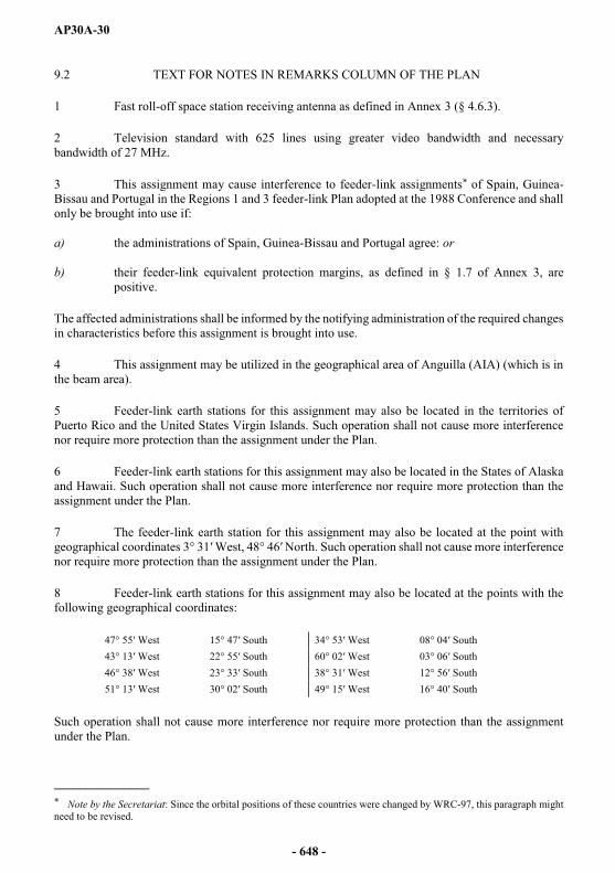
AP30A-30
9.2 TEXT FOR NOTES IN REMARKS COLUMN OF THE PLAN
1 Fast roll-off space station receiving antenna as defined in Annex 3 (§ 4.6.3).
2 Television standard with 625 lines using greater video bandwidth and necessary bandwidth of 27 MHz.
3 This assignment may cause interference to feeder-link assignments* of Spain, Guinea-Bissau and Portugal in the Regions 1 and 3 feeder-link Plan adopted at the 1988 Conference and shall only be brought into use if:
a) the administrations of Spain, Guinea-Bissau and Portugal agree: or
b) their feeder-link equivalent protection margins, as defined in § 1.7 of Annex 3, are positive.
The affected administrations shall be informed by the notifying administration of the required changes in characteristics before this assignment is brought into use.
4 This assignment may be utilized in the geographical area of Anguilla (AIA) (which is in the beam area).
5 Feeder-link earth stations for this assignment may also be located in the territories of Puerto Rico and the United States Virgin Islands. Such operation shall not cause more interference nor require more protection than the assignment under the Plan.
6 Feeder-link earth stations for this assignment may also be located in the States of Alaska and Hawaii. Such operation shall not cause more interference nor require more protection than the assignment under the Plan.
7 The feeder-link earth station for this assignment may also be located at the point with geographical coordinates 3° 31 West, 48° 46 North. Such operation shall not cause more interference nor require more protection than the assignment under the Plan.
8 Feeder-link earth stations for this assignment may also be located at the points with the following geographical coordinates:
47° 55 West 15° 47 South 34° 53 West 08° 04 South43° 13 West 22° 55 South 60° 02 West 03° 06 South46° 38 West 23° 33 South 38° 31 West 12° 56 South51° 13 West 30° 02 South 49° 15 West 16° 40 South
Such operation shall not cause more interference nor require more protection than the assignment under the Plan.
_______________* Note by the Secretariat: Since the orbital positions of these countries were changed by WRC-97, this paragraph might need to be revised.
- 648 -
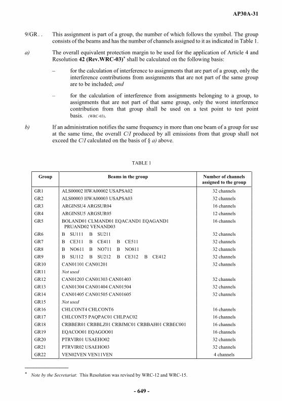
AP30A-31
9/GR . . This assignment is part of a group, the number of which follows the symbol. The group consists of the beams and has the number of channels assigned to it as indicated in Table 1.
a) The overall equivalent protection margin to be used for the application of Article 4 and Resolution 42 (Rev.WRC-03)* shall be calculated on the following basis:
for the calculation of interference to assignments that are part of a group, only the interference contributions from assignments that are not part of the same group are to be included; and
for the calculation of interference from assignments belonging to a group, to assignments that are not part of that same group, only the worst interference contribution from that group shall be used on a test point to test point basis. (WRC-03).
b) If an administration notifies the same frequency in more than one beam of a group for use at the same time, the overall C/I produced by all emissions from that group shall not exceed the C/I calculated on the basis of § a) above.
TABLE 1
Group Beams in the group Number of channels assigned to the group
GR1 ALS00002 HWA00002 USAPSA02 32 channelsGR2 ALS00003 HWA00003 USAPSA03 32 channelsGR3 ARGINSU4 ARGSUR04 16 channelsGR4 ARGINSU5 ARGSUR05 12 channelsGR5 BOLAND01 CLMAND01 EQACAND1 EQAGAND1
PRUAND02 VENAND0316 channels
GR6 B SU111 B SU211 32 channelsGR7 B CE311 B CE411 B CE511 32 channelsGR8 B NO611 B NO711 B NO811 32 channelsGR9 B SU112 B SU212 B CE312 B CE412 32 channelsGR10 CAN01101 CAN01201 32 channelsGR11 Not usedGR12 CAN01203 CAN01303 CAN01403 32 channelsGR13 CAN01304 CAN01404 CAN01504 32 channelsGR14 CAN01405 CAN01505 CAN01605 32 channelsGR15 Not usedGR16 CHLCONT4 CHLCONT6 16 channelsGR17 CHLCONT5 PAQPAC01 CHLPAC02 16 channelsGR18 CRBBER01 CRBBLZ01 CRBJMC01 CRBBAH01 CRBEC001 16 channelsGR19 EQACOO01 EQAGOO01 16 channelsGR20 PTRVIR01 USAEHO02 32 channelsGR21 PTRVIR02 USAEHO03 32 channelsGR22 VEN02VEN VEN11VEN 4 channels
_______________* Note by the Secretariat: This Resolution was revised by WRC-12 and WRC-15.
- 649 -
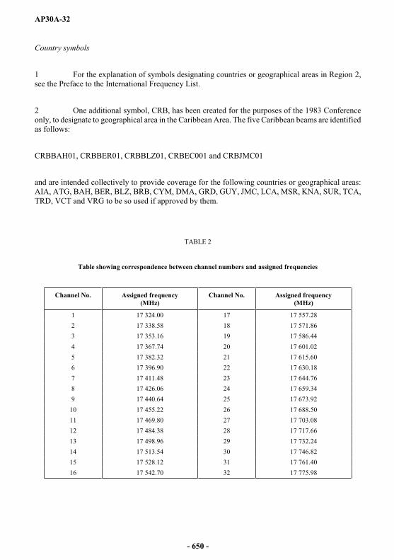
AP30A-32
Country symbols
1 For the explanation of symbols designating countries or geographical areas in Region 2, see the Preface to the International Frequency List.
2 One additional symbol, CRB, has been created for the purposes of the 1983 Conference only, to designate to geographical area in the Caribbean Area. The five Caribbean beams are identified as follows:
CRBBAH01, CRBBER01, CRBBLZ01, CRBEC001 and CRBJMC01
and are intended collectively to provide coverage for the following countries or geographical areas: AIA, ATG, BAH, BER, BLZ, BRB, CYM, DMA, GRD, GUY, JMC, LCA, MSR, KNA, SUR, TCA, TRD, VCT and VRG to be so used if approved by them.
TABLE 2
Table showing correspondence between channel numbers and assigned frequencies
Channel No. Assigned frequency(MHz)
Channel No. Assigned frequency(MHz)
1 17 324.00 17 17 557.282 17 338.58 18 17 571.863 17 353.16 19 17 586.444 17 367.74 20 17 601.025 17 382.32 21 17 615.606 17 396.90 22 17 630.187 17 411.48 23 17 644.768 17 426.06 24 17 659.349 17 440.64 25 17 673.92
10 17 455.22 26 17 688.5011 17 469.80 27 17 703.0812 17 484.38 28 17 717.6613 17 498.96 29 17 732.2414 17 513.54 30 17 746.8215 17 528.12 31 17 761.4016 17 542.70 32 17 775.98
- 650 -

AP30A-33
17 324.00 MHz (1)
1 2 3 4 5 6 7 8 9
ALS00002 1 36.86 6.04 1.11 137 1 87.4 9/GR1ALS000/03 1 37.50 5.60 0.75 132 1 87.4 9/GR2ARGINSU4 1 3.40 0.68 19 1 87.4 9/GR3ARGSUR04 1 3.32 1.50 40 1 87.4 9/GR3B CE311 1 3.04 2.06 174 1 87.4 8 9/GR7B CE312 1 3.44 2.09 174 1 87.4 8 9/GR9B CE411 1 3.86 1.38 49 1 87.4 8 9/GR7B CE412 1 3.57 1.56 52 1 87.4 8 9/GR9B CE511 1 2.44 2.13 104 1 87.4 8 9/GR7B NO611 1 2.85 1.69 165 2 87.4 8 9/GR8B NO711 1 3.54 1.78 126 2 87.4 8 9/GR8B NO811 1 2.37 1.65 73 2 87.4 8 9/GR8B SU111 1 2.76 1.05 50 1 87.4 8 9/GR6B SU112 1 2.47 1.48 56 1 87.4 8 9/GR9B SU211 1 3.22 1.36 60 1 87.4 8 9/GR6B SU212 1 3.20 1.96 58 1 87.4 8 9/GR9BAHIFRB1 1 24.16 1.81 0.70 142 1 87.4BERBERMU 1 32.32 0.60 0.60 90 2 87.4BERBER02 1 32.32 0.60 0.60 90 1 87.4 2 3BOLAND01 1 6.49 2.57 87 1 87.4 9/GR5CAN01101 1 51.08 7.28 1.10 160 1 87.4 9/GR10CAN01201 1 51.08 7.28 1.10 160 1 87.4 9/GR10CAN01202 1 50.02 7.96 2.55 5 1 87.4CAN01203 1 51.08 7.47 1.26 162 1 87.4 9/GR12CAN01303 1 51.08 7.47 1.26 162 1 87.4 9/GR12CAN01304 1 50.48 8.58 2.54 178 1 87.4 9/GR13CAN01403 1 51.08 7.47 1.26 162 1 87.4 9/GR12CAN01404 1 50.48 8.58 2.54 178 1 87.4 9/GR13CAN01405 1 50.20 8.31 2.58 1 1 87.4 9/GR14CAN01504 1 50.48 8.58 2.54 178 1 87.4 9/GR13CAN01505 1 50.20 8.31 2.58 1 1 87.4 9/GR14CAN01605 1 50.20 8.31 2.58 1 1 87.4 9/GR14CAN01606 1 50.03 7.88 2.53 6 1 87.4CHLCONT5 1 2.60 0.68 55 1 87.4 9/GR17CHLPAC02 1 1.36 0.68 69 1 87.4 9/GR17CLMAND01 1 6.49 2.57 87 1 87.4 9/GR5CLM00001 1 5.87 3.98 1.96 118 1 87.4EQACAND1 1 6.49 2.57 87 1 87.4 9/GR5EQAGAND1 1 6.49 2.57 87 1 87.4 9/GR5FLKANT01 1 3.54 0.68 12 1 87.4 2FLKFALKS 1 0.60 0.60 90 1 87.4 2 3GRD00002 1 12.29 0.60 0.60 90 1 87.4HWA00002 1 36.86 6.04 1.11 137 1 87.4 9/GR1HWA00003 1 37.50 5.60 0.75 132 1 87.4 9/GR2MEX01NTE 1 26.01 2.89 2.08 155 1 87.4 1MEX01SUR 1 19.82 3.05 2.09 4 1 87.4 1MEX02NTE 1 26.31 3.84 1.55 148 1 87.4 1MEX02SUR 1 19.88 3.18 1.87 157 1 87.4 1PAQPAC01 6.20 1 0.60 0.60 90 1 87.4 9/GR17PRG00002 1 1.45 1.04 76 1 87.4PRUAND02 1 6.49 2.57 87 1 87.4 9/GR5PTRVIR01 1 36.32 8.24 3.56 171 1 87.4 1 6 9/GR20PTRVIR02 1 36.29 8.27 3.37 168 1 87.4 1 6 9/GR21SPMFRAN3 1 47.51 3.16 0.79 7 1 87.4 2 7TRD00001 1 10.70 0.60 0.60 90 1 87.4URG00001 1 1.02 0.89 11 1 87.4USAEH001 1 36.17 6.42 3.49 12 1 87.4 1 5 6USAEH002 1 36.32 8.24 3.56 171 1 87.4 1 6 9/GR20USAEH003 1 36.29 8.27 3.37 168 1 87.4 1 6 9/GR21USAEH004 1 36.21 8.20 3.12 165 1 87.4 1 5 6USAPSA02 1 36.86 6.04 1.11 137 1 87.4 9/GR1USAPSA03 1 37.50 5.60 0.75 132 1 87.4 9/GR2USAWH101 1 40.68 4.36 2.15 162 1 87.4USAWH102 1 40.74 3.72 1.78 149 1 87.4VENAND03 1 6.49 2.57 87 1 87.4 9/GR5VRG00001 1 18.48 0.60 0.60 90 1 87.4 4
- 651 -
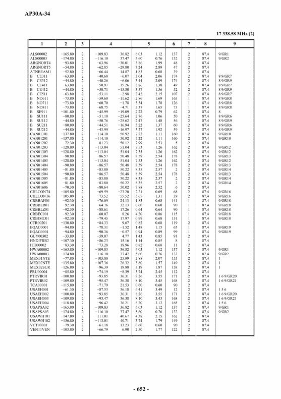
AP30A-34
17 338.58 MHz (2)
1 2 3 4 5 6 7 8 9
ALS00002 2 36.82 6.03 1.12 137 2 87.4 9/GR1ALS00003 2 37.47 5.60 0.76 132 2 87.4 9/GR2ARGNORT4 2 3.86 1.99 48 2 87.4ARGNORT5 80 2 3.24 2.89 47 2 87.4ATNBEAM1 2 14.87 1.83 0.68 39 2 87.4B CE311 2 3.04 2.06 174 2 87.4 8 9/GR7B CE312 2 3.44 2.09 174 2 87.4 8 9/GR9B CE411 2 3.86 1.38 49 2 87.4 8 9/GR7B CE412 2 3.57 1.56 52 2 87.4 8 9/GR9B CE511 2 2.42 2.15 107 2 87.4 8 9/GR7B NO611 2 2.86 1.69 165 1 87.4 8 9/GR8B NO711 2 3.54 1.78 126 1 87.4 8 9/GR8B NO811 2 2.37 1.65 73 1 87.4 8 9/GR8B SE911 2 2.22 0.79 62 2 87.4 8B SU111 2 2.76 1.06 50 2 87.4 8 9/GR6B SU112 2 2.47 1.48 56 2 87.4 8 9/GR9B SU211 2 4.51 3.22 1.37 60 2 87.4 8 9/GR6B SU212 2 3.27 1.92 59 2 87.4 8 9/GR9CAN01101 2 50.92 7.22 1.11 160 2 87.4 9/GR10CAN01201 2 50.92 7.22 1.11 160 2 87.4 9/GR10CAN01202 2 50.12 7.99 2.53 5 2 87.4CAN01203 2 51.04 7.53 1.26 162 2 87.4 9/GR12CAN01303 2 51.04 7.53 1.26 162 2 87.4 9/GR12CAN01304 2 50.48 8.59 2.54 178 2 87.4 9/GR13CAN01403 2 51.04 7.53 1.26 162 2 87.4 9/GR12CAN01404 2 50.48 8.59 2.54 178 2 87.4 9/GR13CAN01405 2 50.22 8.35 2.57 2 2 87.4 9/GR14CAN01504 2 50.48 8.59 2.54 178 2 87.4 9/GR13CAN01505 2 50.22 8.35 2.57 2 2 87.4 9/GR14CAN01605 2 50.22 8.35 2.57 2 2 87.4 9/GR14CAN01606 2 50.02 7.88 2.52 6 2 87.4CHLCONT4 2 2.21 0.69 68 2 87.4 9/GR16CHLCONT6 2 3.65 1.31 39 2 87.4 9/GR16CRBBAH01 2 24.13 1.83 0.68 141 1 87.4 9/GR18CRBBER01 2 32.13 0.60 0.60 90 1 87.4 9/GR18CRBBLZ01 2 17.26 0.64 0.64 90 1 87.4 9/GR18CRBEC001 2 8.26 4.20 0.86 115 1 87.4 9/GR18CRBJMC01 2 17.97 0.99 0.68 151 1 87.4 9/GR18CTR00201 2 9.67 0.82 0.68 119 2 87.4EQAC0001 2 1.48 1.15 65 1 87.4 9/GR19EQAG0001 2 0.94 0.89 99 1 87.4 9/GR19GUY00302 2 4.77 1.43 0.85 91 2 87.4HNDIFRB2 2 3 15.16 1.14 0.85 8 1 87.4HTI00002 2 18.96 0.82 0.68 11 2 87.4HWA00002 2 36.82 6.03 1.12 137 2 87.4 9/GR1HWA00003 2 37.47 5.60 0.76 132 2 87.4 9/GR2MEX01NTE 2 25.99 2.88 2.07 155 2 87.4 1MEX02NTE 2 26.32 3.80 1.57 149 2 87.4 1MEX02SUR 2 19.88 3.19 1.87 158 2 87.4 1PRU00004 2 3.74 2.45 112 2 87.4PTRVIR01 2 36.31 8.26 3.55 171 2 87.4 1 6 9/GR20PTRVIR02 2 95.47 36.38 8.10 3.45 168 2 87.4 1 6 9/GR21TCA00001 2 21.53 0.60 0.60 90 2 87.4USAEH001 2 36.18 6.41 3.49 12 2 87.4 1 5 6USAEH002 2 36.31 8.26 3.55 171 2 87.4 1 6 9/GR20USAEH003 2 36.38 8.10 3.45 168 2 87.4 1 6 9/GR21USAEH004 2 36.21 8.20 3.12 165 2 87.4 1 5 6USAPSA02 2 36.82 6.03 1.12 137 2 87.4 9/GR1USAPSA03 2 37.47 5.60 0.76 132 2 87.4 9/GR2USAWH101 2 40.67 4.38 2.15 162 2 87.4USAWH102 2 40.71 3.74 1.79 149 2 87.4VCT00001 2 13.23 0.60 0.60 90 2 87.4VEN11VEN 2 6.90 2.50 1.77 122 2 87.4
- 652 -

AP30A-35
17 353.16 MHz (3)
1 2 3 4 5 6 7 8 9
ALS00002 3 36.86 6.04 1.11 137 1 87.4 9/GR1ALS00003 3 37.50 5.60 0.75 132 1 87.4 9/GR2ARGINSU4 3 3.40 0.68 19 1 87.4 9/GR3ARGINSU5 3 3.77 0.70 13 1 87.4 9/GR4ARGSUR04 3 3.32 1.50 40 1 87.4 9/GR3ARGSUR05 3 2.54 2.38 152 1 87.4 9/GR4ATGSJN01 3 17.07 0.60 0.60 90 1 87.4B CE311 3 3.04 2.06 174 1 87.4 8 9/GR7B CE312 3 3.44 2.09 174 1 87.4 8 9/GR9B CE411 3 0.97 3.86 1.38 49 1 87.4 8 9/GR7B CE412 3 3.57 1.56 52 1 87.4 8 9/GR9B CE511 3 2.44 2.13 104 1 87.4 8 9/GR7B NO611 3 2.85 1.69 165 2 87.4 8 9/GR8B NO711 3 3.54 1.78 126 2 87.4 8 9/GR8B NO811 3 2.37 1.65 73 2 87.4 8 9/GR8B SU111 3 2.76 1.05 50 1 87.4 8 9/GR6B SU112 3 2.47 1.48 56 1 87.4 8 9/GR9B SU211 3 3.22 1.36 60 1 87.4 8 9/GR6B SU212 3 3.20 1.96 58 1 87.4 8 9/GR9BERBERMU 3 32.32 0.60 0.60 90 2 87.4BOLAND01 3 6.49 2.57 87 1 87.4 9/GR5BOL00001 3 2.52 2.19 85 1 87.4BRB00001 3 .85 12.93 0.60 0.60 90 2 87.4CAN01101 3 51.08 7.28 1.10 160 1 87.4 9/GR10CAN01201 3 51.08 7.28 1.10 160 1 87.4 9/GR10CAN01202 3 50.02 7.96 2.55 5 1 87.4CAN01203 3 51.08 7.47 1.26 162 1 87.4 9/GR12CAN01303 3 51.08 7.47 1.26 162 1 87.4 9/GR12CAN01304 3 50.48 8.58 2.54 178 1 87.4 9/GR13CAN01403 3 51.08 7.47 1.26 162 1 87.4 9/GR12CAN01404 3 50.48 8.58 2.54 178 1 87.4 9/GR13CAN01405 3 50.20 8.31 2.58 1 1 87.4 9/GR14CAN01504 3 50.48 8.58 2.54 178 1 87.4 9/GR13CAN01505 3 50.20 8.31 2.58 1 1 87.4 9/GR14CAN01605 3 50.20 8.31 2.58 1 1 87.4 9/GR14CAN01606 3 0.77 50.03 7.88 2.53 6 1 87.4CHLCONT5 3 2.60 0.68 55 1 87.4 9/GR17CHLPAC02 3 1.36 0.68 69 1 87.4 9/GR17CLMAND01 3 6.49 2.57 87 1 87.4 9/GR5CLM00001 3 5.87 3.98 1.96 118 1 87.4CUB00001 3 21.62 2.24 0.68 168 1 87.4EQACAND1 3 6.49 2.57 87 1 87.4 9/GR5EQAGAND1 3 6.49 2.57 87 1 87.4 9/GR5GRD00002 3 12.29 0.60 0.60 90 1 87.4GRD00059 3 1.58 12.29 0.60 0.60 90 1 87.4GRLDNK01 3 66.56 2.70 0.82 173 1 87.4 2HWA00002 3 36.86 6.04 1.11 137 1 87.4 9/GR1HWA00003 3 37.50 5.60 0.75 132 1 87.4 9/GR2MEX01NTE 3 26.01 2.89 2.08 155 1 87.4 1MEX01SUR 3 19.82 3.05 2.09 4 1 87.4 1MEX02NTE 3 26.31 3.84 1.55 148 1 87.4 1MEX02SUR 3 19.88 3.18 1.87 157 1 87.4 1PAQPAC01 3 0.60 0.60 90 1 87.4 9/GR17PRG00002 3 1.45 1.04 76 1 87.4PRUAND02 3 6.49 2.57 87 1 87.4 9/GR5PTRVIR01 3 36.32 8.24 3.56 171 1 87.4 1 6 9/GR20PTRVIR02 3 36.29 8.27 3.37 168 1 87.4 1 6 9/GR21SURINAM2 3 4.35 1.00 0.69 86 1 87.4URG00001 3 1.02 0.89 11 1 87.4USAEH001 3 36.17 6.42 3.49 12 1 87.4 1 5 6USAEH002 3 36.32 8.24 3.56 171 1 87.4 1 6 9/GR20USAEH003 3 36.29 8.27 3.37 168 1 87.4 1 6 9/GR21USAEH004 3 36.21 8.20 3.12 165 1 87.4 1 5 6USAPSA02 3 36.86 6.04 1.11 137 1 87.4 9/GR1USAPSA03 3 37.50 5.60 0.75 132 1 87.4 9/GR2USAWH101 3 40.68 4.36 2.15 162 1 87.4USAWH102 57.20 3 40.74 3.72 1.78 149 1 87.4VENAND03 3 6.49 2.57 87 1 87.4 9/GR5
- 653 -

AP30A-36
17 367.74 MHz (4)
1 2 3 4 5 6 7 8 9
ALS00002 4 36.82 6.03 1.12 137 2 87.4 9/GR1ALS00003 4 37.47 5.60 0.76 132 2 87.4 9/GR2ARGNORT4 4 3.86 1.99 48 2 87.4ARGNORT5 4 3.24 2.89 47 2 87.4B CE311 4 3.04 2.06 174 2 87.4 8 9/GR7B CE312 4 3.44 2.09 174 2 87.4 8 9/GR9B CE411 4 50.97 3.86 1.38 49 2 87.4 8 9/GR7B CE412 4 3.57 1.56 52 2 87.4 8 9/GR9B CE511 4 2.42 2.15 107 2 87.4 8 9/GR7B NO611 4 2.86 1.69 165 1 87.4 8 9/GR8B NO711 4 3.54 1.78 126 1 87.4 8 9/GR8B NO811 4 2.37 1.65 73 1 87.4 8 9/GR8B SE911 4 2.22 0.79 62 2 87.4 8B SU111 4 2.76 1.06 50 2 87.4 8 9/GR6B SU112 4 2.47 1.48 56 2 87.4 8 9/GR9B SU211 4 3.22 1.37 60 2 87.4 8 9/GR6B SU212 4 3.27 1.92 59 2 87.4 8 9/GR9CAN01101 4 50.92 7.22 1.11 160 2 87.4 9/GR10CAN01201 4 50.92 7.22 1.11 160 2 87.4 9/GR10CAN01202 4 50.12 7.99 2.53 5 2 87.4CAN01203 4 51.04 7.53 1.26 162 2 87.4 9/GR12CAN01303 4 51.04 7.53 1.26 162 2 87.4 9/GR12CAN01304 4 50.48 8.59 2.54 178 2 87.4 9/GR13CAN01403 4 51.04 7.53 1.26 162 2 87.4 9/GR12CAN01404 4 50.48 8.59 2.54 178 2 87.4 9/GR13CAN01405 4 50.22 8.35 2.57 2 2 87.4 9/GR14CAN01504 4 50.48 8.59 2.54 178 2 87.4 9/GR13CAN01505 4 50.22 8.35 2.57 2 2 87.4 9/GR14CAN01605 4 50.22 8.35 2.57 2 2 87.4 9/GR14CAN01606 4 50.02 7.88 2.52 6 2 87.4CHLCONT4 4 2.21 0.69 68 2 87.4 9/GR16CHLCONT6 4 3.65 1.31 39 2 87.4 9/GR16CRBBAH01 4 24.13 1.83 0.68 141 1 87.4 9/GR18CRBBER01 4 32.13 0.60 0.60 90 1 87.4 9/GR18CRBBLZ01 4 17.26 0.64 0.64 90 1 87.4 9/GR18CRBEC001 4 8.26 4.20 0.86 115 1 87.4 9/GR18CRBJMC01 4 17.97 0.99 0.68 151 1 87.4 9/GR18CYM00001 4 19.57 0.60 0.60 90 2 87.4DOMIFRB2 4 18.79 0.98 0.69 167 2 87.4EQAC0001 4 1.48 1.15 65 1 87.4 9/GR19EQAG0001 4 0.94 0.89 99 1 87.4 9/GR19GUFMGG02 4 8.47 4.16 0.81 123 2 87.4 2 7HWA00002 4 36.82 6.03 1.12 137 2 87.4 9/GR1HWA00003 4 37.47 5.60 0.76 132 2 87.4 9/GR2JMC00005 4 18.12 0.60 0.60 90 2 87.4LCAIFRB1 4 5 13.90 0.60 0.60 90 2 87.4MEX01NTE 4 25.99 2.88 2.07 155 2 87.4 1MEX02NTE 4 26.32 3.80 1.57 149 2 87.4 1MEX02SUR 4 19.88 3.19 1.87 158 2 87.4 1PRU00004 4 3.74 2.45 112 2 87.4PTRVIR01 4 36.31 8.26 3.55 171 2 87.4 1 6 9/GR20PTRVIR02 4 36.38 8.10 3.45 168 2 87.4 1 6 9/GR21SLVIFRB2 4 13.59 0.60 0.60 90 1 87.4USAEH001 4 36.18 6.41 3.49 12 2 87.4 1 5 6USAEH002 4 36.31 8.26 3.55 171 2 87.4 1 6 9/GR20USAEH003 4 36.38 8.10 3.45 168 2 87.4 1 6 9/GR21USAEH004 4 36.21 8.20 3.12 165 2 87.4 1 5 6USAPSA02 4 36.82 6.03 1.12 137 2 87.4 9/GR1USAPSA03 4 6.10 37.47 5.60 0.76 132 2 87.4 9/GR2USAWH101 4 40.67 4.38 2.15 162 2 87.4USAWH102 4 40.71 3.74 1.79 149 2 87.4VEN11VEN 4 6.90 2.50 1.77 122 2 87.4
- 654 -

AP30A-37
17 382.32 MHz (5)
1 2 3 4 5 6 7 8 9
ALS00002 66.20 5 36.86 6.04 1.11 137 1 87.4 9/GR1ALS00003 5 37.50 5.60 0.75 132 1 87.4 9/GR2ARGINSU4 5 3.40 0.68 19 1 87.4 9/GR3ARGSUR04 5 3.32 1.50 40 1 87.4 9/GR3B CE311 5 07 3.04 2.06 174 1 87.4 89/GR7B CE312 5 3.44 2.09 174 1 87.4 89/GR9B CE411 5 3.86 1.38 49 1 87.4 89/GR7B CE412 5 3.57 1.56 52 1 87.4 89/GR9B CE511 5 2.44 2.13 104 1 87.4 89/GR7B NO611 5 2.85 1.69 165 2 87.4 89/GR8B NO711 5 3.54 1.78 126 2 87.4 89/GR8B NO811 5 2.37 1.65 73 2 87.4 89/GR8B SU111 5 2.76 1.05 50 1 87.4 89/GR6B SU112 5 2.47 1.48 56 1 87.4 89/GR9B SU211 5 3.22 1.36 60 1 87.4 89/GR6B SU212 5 3.20 1.96 58 1 87.4 89/GR9BAHIFRB1 5 24.16 1.81 0.70 142 1 87.4BERBERMU 5 .77 32.32 0.60 0.60 90 2 87.4BERBER02 5 32.32 0.60 0.60 90 1 87.4 2 3BOLAND01 5 6.49 2.57 87 1 87.4 9/GR5CAN01101 5 51.08 7.28 1.10 160 1 87.4 9/GR10CAN01201 5 51.08 7.28 1.10 160 1 87.4 9/GR10CAN01202 5 50.02 7.96 2.55 5 1 87.4CAN01203 5 51.08 7.47 1.26 162 1 87.4 9/GR12CAN01303 5 51.08 7.47 1.26 162 1 87.4 9/GR12CAN01304 5 50.48 8.58 2.54 178 1 87.4 9/GR13CAN01403 5 51.08 7.47 1.26 162 1 87.4 9/GR12CAN01404 5 50.48 8.58 2.54 178 1 87.4 9/GR13CAN01405 5 50.20 8.31 2.58 1 1 87.4 9/GR14CAN01504 5 50.48 8.58 2.54 178 1 87.4 9/GR13CAN01505 5 .11 50.20 8.31 2.58 1 1 87.4 9/GR14CAN01605 5 50.20 8.31 2.58 1 1 87.4 9/GR14CAN01606 5 50.03 7.88 2.53 6 1 87.4CHLCONT5 5 2.60 0.68 55 1 87.4 9/GR17CHLPAC02 5 1.36 0.68 69 1 87.4 9/GR17CLMAND01 5 6.49 2.57 87 1 87.4 9/GR5CLM00001 5 5.87 3.98 1.96 118 1 87.4EQACAND1 5 6.49 2.57 87 1 87.4 9/GR5EQAGAND1 5 6.49 2.57 87 1 87.4 9/GR5FLKANT01 .20 5 3.54 0.68 12 1 87.4 2FLKFALKS 5 0.60 0.60 90 1 87.4 2 3GRD00002 5 12.29 0.60 0.60 90 1 87.4HWA00002 5 36.86 6.04 1.11 137 1 87.4 9/GR1HWA00003 5 37.50 5.60 0.75 132 1 87.4 9/GR2MEX01NTE 5 26.01 2.89 2.08 155 1 87.4 1MEX01SUR 5 19.82 3.05 2.09 4 1 87.4 1MEX02NTE 5 26.31 3.84 1.55 148 1 87.4 1MEX02SUR 5 19.88 3.18 1.87 157 1 87.4 1PAQPAC01 0 5 0.60 0.60 90 1 87.4 9/GR17PRG00002 5 1.45 1.04 76 1 87.4PRUAND02 5 6.49 2.57 87 1 87.4 9/GR5PTRVIR01 5 36.32 8.24 3.56 171 1 87.4 169/GR20PTRVIR02 5 36.29 8.27 3.37 168 1 87.4 169/GR21SPMFRAN3 5 47.51 3.16 0.79 7 1 87.4 2 7TRD00001 5 10.70 0.60 0.60 90 1 87.4URG00001 5 1.02 0.89 11 1 87.4USAEH001 5 36.17 6.42 3.49 12 1 87.4 156USAEH002 5 36.32 8.24 3.56 171 1 87.4 169/GR20USAEH003 5 36.29 8.27 3.37 168 1 87.4 169/GR21USAEH004 5 36.21 8.20 3.12 165 1 87.4 156USAPSA02 5 36.86 6.04 1.11 137 1 87.4 9/GR1USAPSA03 5 37.50 5.60 0.75 132 1 87.4 9/GR2USAWH101 5 40.68 4.36 2.15 162 1 87.4USAWH102 5 40.74 3.72 1.78 149 1 87.4VENAND03 5 6.49 2.57 87 1 87.4 9/GR5VRG00001 5 18.48 0.60 0.60 90 1 87.4 4
- 655 -

AP30A-38
17 396.90 MHz (6)
1 2 3 4 5 6 7 8 9
ALS00002 6 36.82 6.03 1.12 137 2 87.4 9/GR1ALS00003 6 37.47 5.60 0.76 132 2 87.4 9/GR2ARGNORT4 6 3.86 1.99 48 2 87.4ARGNORT5 6 3.24 2.89 47 2 87.4ATNBEAM1 6 14.87 1.83 0.68 39 2 87.4B CE311 6 3.04 2.06 174 2 87.4 8 9/GR7B CE312 6 3.44 2.09 174 2 87.4 8 9/GR9B CE411 6 3.86 1.38 49 2 87.4 8 9/GR7B CE412 6 3.57 1.56 52 2 87.4 8 9/GR9B CE511 6 2.42 2.15 107 2 87.4 8 9/GR7B NO611 6 2.86 1.69 165 1 87.4 8 9/GR8B NO711 6 3.54 1.78 126 1 87.4 8 9/GR8B NO811 6 2.37 1.65 73 1 87.4 8 9/GR8B SE911 6 2.22 0.79 62 2 87.4 8B SU111 6 2.76 1.06 50 2 87.4 8 9/GR6B SU112 6 2.47 1.48 56 2 87.4 8 9/GR9B SU211 6 1 3.22 1.37 60 2 87.4 8 9/GR6B SU212 6 3.27 1.92 59 2 87.4 8 9/GR9CAN01101 6 50.92 7.22 1.11 160 2 87.4 9/GR10CAN01201 6 50.92 7.22 1.11 160 2 87.4 9/GR10CAN01202 6 50.12 7.99 2.53 5 2 87.4CAN01203 6 51.04 7.53 1.26 162 2 87.4 9/GR12CAN01303 6 51.04 7.53 1.26 162 2 87.4 9/GR12CAN01304 6 50.48 8.59 2.54 178 2 87.4 9/GR13CAN01403 6 51.04 7.53 1.26 162 2 87.4 9/GR12CAN01404 6 50.48 8.59 2.54 178 2 87.4 9/GR13CAN01405 6 50.22 8.35 2.57 2 2 87.4 9/GR14CAN01504 6 50.48 8.59 2.54 178 2 87.4 9/GR13CAN01505 6 50.22 8.35 2.57 2 2 87.4 9/GR14CAN01605 .80 6 50.22 8.35 2.57 2 2 87.4 9/GR14CAN01606 6 50.02 7.88 2.52 6 2 87.4CHLCONT4 6 2.21 0.69 68 2 87.4 9/GR16CHLCONT6 6 3.65 1.31 39 2 87.4 9/GR16CRBBAH01 6 24.13 1.83 0.68 141 1 87.4 9/GR18CRBBER01 6 32.13 0.60 0.60 90 1 87.4 9/GR18CRBBLZ01 6 17.26 0.64 0.64 90 1 87.4 9/GR18CRBEC001 6 8.26 4.20 0.86 115 1 87.4 9/GR18CRBJMC01 6 17.97 0.99 0.68 151 1 87.4 9/GR18CTR00201 6 9.67 0.82 0.68 119 2 87.4EQAC0001 6 1.48 1.15 65 1 87.4 9/GR19EQAG0001 6 0.94 0.89 99 1 87.4 9/GR19GUY00302 6 4.77 1.43 0.85 91 2 87.4HNDIFRB2 6 15.16 1.14 0.85 8 1 87.4HTI00002 6 18.96 0.82 0.68 11 2 87.4HWA00002 6 36.82 6.03 1.12 137 2 87.4 9/GR1HWA00003 6 37.47 5.60 0.76 132 2 87.4 9/GR2MEX01NTE 6 25.99 2.88 2.07 155 2 87.4 1MEX02NTE 6 26.32 3.80 1.57 149 2 87.4 1MEX02SUR 6 19.88 3.19 1.87 158 2 87.4 1PRU00004 6 3.74 2.45 112 2 87.4PTRVIR01 6 36.31 8.26 3.55 171 2 87.4 1 6 9/GR20PTRVIR02 6 47 36.38 8.10 3.45 168 2 87.4 1 6 9/GR21TCA00001 6 21.53 0.60 0.60 90 2 87.4USAEH001 6 36.18 6.41 3.49 12 2 87.4 1 5 6USAEH002 6 36.31 8.26 3.55 171 2 87.4 1 6 9/GR20USAEH003 6 36.38 8.10 3.45 168 2 87.4 1 6 9/GR21USAEH004 6 36.21 8.20 3.12 165 2 87.4 1 5 6USAPSA02 6 36.82 6.03 1.12 137 2 87.4 9/GR1USAPSA03 6 37.47 5.60 0.76 132 2 87.4 9/GR2USAWH101 6 40.67 4.38 2.15 162 2 87.4USAWH102 6 40.71 3.74 1.79 149 2 87.4VCT00001 6 13.23 0.60 0.60 90 2 87.4VEN11VEN 6 6.90 2.50 1.77 122 2 87.4
- 656 -
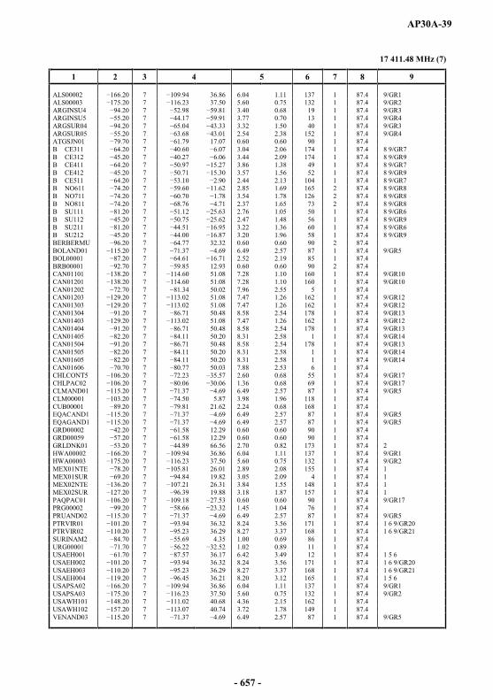
AP30A-39
17 411.48 MHz (7)
1 2 3 4 5 6 7 8 9
ALS00002 7 36.86 6.04 1.11 137 1 87.4 9/GR1ALS00003 7 37.50 5.60 0.75 132 1 87.4 9/GR2ARGINSU4 7 3.40 0.68 19 1 87.4 9/GR3ARGINSU5 7 3.77 0.70 13 1 87.4 9/GR4ARGSUR04 7 3.32 1.50 40 1 87.4 9/GR3ARGSUR05 7 2.54 2.38 152 1 87.4 9/GR4ATGSJN01 7 17.07 0.60 0.60 90 1 87.4B CE311 7 3.04 2.06 174 1 87.4 8 9/GR7B CE312 7 3.44 2.09 174 1 87.4 8 9/GR9B CE411 7 3.86 1.38 49 1 87.4 8 9/GR7B CE412 7 3.57 1.56 52 1 87.4 8 9/GR9B CE511 7 2.44 2.13 104 1 87.4 8 9/GR7B NO611 7 2.85 1.69 165 2 87.4 8 9/GR8B NO711 7 3.54 1.78 126 2 87.4 8 9/GR8B NO811 7 2.37 1.65 73 2 87.4 8 9/GR8B SU111 7 2.76 1.05 50 1 87.4 8 9/GR6B SU112 7 2.47 1.48 56 1 87.4 8 9/GR9B SU211 7 3.22 1.36 60 1 87.4 8 9/GR6B SU212 7 3.20 1.96 58 1 87.4 8 9/GR9BERBERMU 7 32.32 0.60 0.60 90 2 87.4BOLAND01 7 6.49 2.57 87 1 87.4 9/GR5BOL00001 7 2.52 2.19 85 1 87.4BRB00001 7 12.93 0.60 0.60 90 2 87.4CAN01101 7 51.08 7.28 1.10 160 1 87.4 9/GR10CAN01201 7 51.08 7.28 1.10 160 1 87.4 9/GR10CAN01202 7 50.02 7.96 2.55 5 1 87.4CAN01203 7 51.08 7.47 1.26 162 1 87.4 9/GR12CAN01303 7 51.08 7.47 1.26 162 1 87.4 9/GR12CAN01304 7 50.48 8.58 2.54 178 1 87.4 9/GR13CAN01403 7 51.08 7.47 1.26 162 1 87.4 9/GR12CAN01404 7 50.48 8.58 2.54 178 1 87.4 9/GR13CAN01405 7 50.20 8.31 2.58 1 1 87.4 9/GR14CAN01504 7 50.48 8.58 2.54 178 1 87.4 9/GR13CAN01505 7 50.20 8.31 2.58 1 1 87.4 9/GR14CAN01605 7 50.20 8.31 2.58 1 1 87.4 9/GR14CAN01606 7 50.03 7.88 2.53 6 1 87.4CHLCONT5 7 2.60 0.68 55 1 87.4 9/GR17CHLPAC02 7 1.36 0.68 69 1 87.4 9/GR17CLMAND01 7 6.49 2.57 87 1 87.4 9/GR5CLM00001 7 5.87 3.98 1.96 118 1 87.4CUB00001 7 21.62 2.24 0.68 168 1 87.4EQACAND1 7 6.49 2.57 87 1 87.4 9/GR5EQAGAND1 7 6.49 2.57 87 1 87.4 9/GR5GRD00002 7 12.29 0.60 0.60 90 1 87.4GRD00059 7 12.29 0.60 0.60 90 1 87.4GRLDNK01 7 66.56 2.70 0.82 173 1 87.4 2HWA00002 7 36.86 6.04 1.11 137 1 87.4 9/GR1HWA00003 7 37.50 5.60 0.75 132 1 87.4 9/GR2MEX01NTE 7 26.01 2.89 2.08 155 1 87.4 1MEX01SUR 7 19.82 3.05 2.09 4 1 87.4 1MEX02NTE 7 26.31 3.84 1.55 148 1 87.4 1MEX02SUR 7 19.88 3.18 1.87 157 1 87.4 1PAQPAC01 7 0.60 0.60 90 1 87.4 9/GR17PRG00002 7 66 1.45 1.04 76 1 87.4PRUAND02 7 6.49 2.57 87 1 87.4 9/GR5PTRVIR01 7 36.32 8.24 3.56 171 1 87.4 1 6 9/GR20PTRVIR02 7 36.29 8.27 3.37 168 1 87.4 1 6 9/GR21SURINAM2 7 4.35 1.00 0.69 86 1 87.4URG00001 7 1.02 0.89 11 1 87.4USAEH001 7 36.17 6.42 3.49 12 1 87.4 1 5 6USAEH002 7 36.32 8.24 3.56 171 1 87.4 1 6 9/GR20USAEH003 7 36.29 8.27 3.37 168 1 87.4 1 6 9/GR21USAEH004 7 36.21 8.20 3.12 165 1 87.4 1 5 6USAPSA02 7 36.86 6.04 1.11 137 1 87.4 9/GR1USAPSA03 7 37.50 5.60 0.75 132 1 87.4 9/GR2USAWH101 7 40.68 4.36 2.15 162 1 87.4USAWH102 0 7 40.74 3.72 1.78 149 1 87.4VENAND03 7 6.49 2.57 87 1 87.4 9/GR5
- 657 -

AP30A-40
17 426.06 MHz (8)
1 2 3 4 5 6 7 8 9
ALS00002 8 36.82 6.03 1.12 137 2 87.4 9/GR1ALS00003 8 37.47 5.60 0.76 132 2 87.4 9/GR2ARGNORT4 8 3.86 1.99 48 2 87.4ARGNORT5 8 3.24 2.89 47 2 87.4B CE311 8 3.04 2.06 174 2 87.4 8 9/GR7B CE312 8 3.44 2.09 174 2 87.4 8 9/GR9B CE411 8 7 3.86 1.38 49 2 87.4 8 9/GR7B CE412 8 3.57 1.56 52 2 87.4 8 9/GR9B CE511 8 2.42 2.15 107 2 87.4 8 9/GR7B NO611 8 2.86 1.69 165 1 87.4 8 9/GR8B NO711 8 3.54 1.78 126 1 87.4 8 9/GR8B NO811 8 2.37 1.65 73 1 87.4 8 9/GR8B SE911 8 2.22 0.79 62 2 87.4 8B SU111 8 2.76 1.06 50 2 87.4 8 9/GR6B SU112 8 2.47 1.48 56 2 87.4 8 9/GR9B SU211 8 3.22 1.37 60 2 87.4 8 9/GR6B SU212 8 3.27 1.92 59 2 87.4 8 9/GR9CAN01101 8 50.92 7.22 1.11 160 2 87.4 9/GR10CAN01201 8 50.92 7.22 1.11 160 2 87.4 9/GR10CAN01202 2.30 8 50.12 7.99 2.53 5 2 87.4CAN01203 8 51.04 7.53 1.26 162 2 87.4 9/GR12CAN01303 8 51.04 7.53 1.26 162 2 87.4 9/GR12CAN01304 8 50.48 8.59 2.54 178 2 87.4 9/GR13CAN01403 8 51.04 7.53 1.26 162 2 87.4 9/GR12CAN01404 8 50.48 8.59 2.54 178 2 87.4 9/GR13CAN01405 8 50.22 8.35 2.57 2 2 87.4 9/GR14CAN01504 8 50.48 8.59 2.54 178 2 87.4 9/GR13CAN01505 8 50.22 8.35 2.57 2 2 87.4 9/GR14CAN01605 8 50.22 8.35 2.57 2 2 87.4 9/GR14CAN01606 8 50.02 7.88 2.52 6 2 87.4CHLCONT4 8 2.21 0.69 68 2 87.4 9/GR16CHLCONT6 8 3.65 1.31 39 2 87.4 9/GR16CRBBAH01 30 8 24.13 1.83 0.68 141 1 87.4 9/GR18CRBBER01 8 32.13 0.60 0.60 90 1 87.4 9/GR18CRBBLZ01 8 17.26 0.64 0.64 90 1 87.4 9/GR18CRBEC001 8 8.26 4.20 0.86 115 1 87.4 9/GR18CRBJMC01 8 17.97 0.99 0.68 151 1 87.4 9/GR18CYM00001 8 19.57 0.60 0.60 90 2 87.4DOMIFRB2 8 18.79 0.98 0.69 167 2 87.4EQAC0001 8 1.48 1.15 65 1 87.4 9/GR19EQAG0001 8 0.94 0.89 99 1 87.4 9/GR19GUFMGG02 8 8.47 4.16 0.81 123 2 87.4 2 7HWA00002 8 36.82 6.03 1.12 137 2 87.4 9/GR1HWA00003 8 37.47 5.60 0.76 132 2 87.4 9/GR2JMC00005 8 18.12 0.60 0.60 90 2 87.4LCAIFRB1 8 13.90 0.60 0.60 90 2 87.4MEX01NTE 8 25.99 2.88 2.07 155 2 87.4 1MEX02NTE 8 26.32 3.80 1.57 149 2 87.4 1MEX02SUR 8 19.88 3.19 1.87 158 2 87.4 1PRU00004 8 3.74 2.45 112 2 87.4PTRVIR01 8 36.31 8.26 3.55 171 2 87.4 1 6 9/GR20PTRVIR02 8 36.38 8.10 3.45 168 2 87.4 1 6 9/GR21SLVIFRB2 8 13.59 0.60 0.60 90 1 87.4USAEH001 8 36.18 6.41 3.49 12 2 87.4 1 5 6USAEH002 8 93.85 36.31 8.26 3.55 71 2 87.4 1 6 9/GR20USAEH003 8 36.38 8.10 3.45 168 2 87.4 1 6 9/GR21USAEH004 8 36.21 8.20 3.12 165 2 87.4 1 5 6USAPSA02 8 36.82 6.03 1.12 137 2 87.4 9/GR1USAPSA03 8 37.47 5.60 0.76 132 2 87.4 9/GR2USAWH101 8 40.67 4.38 2.15 162 2 87.4USAWH102 8 40.71 3.74 1.79 149 2 87.4VEN11VEN 8 6.90 2.50 1.77 122 2 87.4
- 658 -

AP30A-41
17 440.64 MHz (9)
1 2 3 4 5 6 7 8 9
ALS00002 0 9 36.86 6.04 1.11 137 1 87.4 9/GR1ALS00003 9 37.50 5.60 0.75 132 1 87.4 9/GR2ARGINSU4 9 3.40 0.68 19 1 87.4 9/GR3ARGSUR04 9 3.32 1.50 40 1 87.4 9/GR3B CE311 9 3.04 2.06 174 1 87.4 8 9/GR7B CE312 9 3.44 2.09 174 1 87.4 8 9/GR9B CE411 9 3.86 1.38 49 1 87.4 8 9/GR7B CE412 9 3.57 1.56 52 1 87.4 8 9/GR9B CE511 9 2.44 2.13 104 1 87.4 8 9/GR7B NO611 9 2.85 1.69 165 2 87.4 8 9/GR8B NO711 9 3.54 1.78 126 2 87.4 8 9/GR8B NO811 9 2.37 1.65 73 2 87.4 8 9/GR8B SU111 9 2.76 1.05 50 1 87.4 8 9/GR6B SU112 9 2.47 1.48 56 1 87.4 8 9/GR9B SU211 9 3.22 1.36 60 1 87.4 8 9/GR6B SU212 9 3.20 1.96 58 1 87.4 8 9/GR9BAHIFRB1 9 24.16 1.81 0.70 142 1 87.4BERBERMU 9 32.32 0.60 0.60 90 2 87.4BERBER02 9 32.32 0.60 0.60 90 1 87.4 2 3BOLAND01 9 6.49 2.57 87 1 87.4 9/GR5CAN01101 9 51.08 7.28 1.10 160 1 87.4 9/GR10CAN01201 9 51.08 7.28 1.10 160 1 87.4 9/GR10CAN01202 9 50.02 7.96 2.55 5 1 87.4CAN01203 9 51.08 7.47 1.26 162 1 87.4 9/GR12CAN01303 9 51.08 7.47 1.26 162 1 87.4 9/GR12CAN01304 9 50.48 8.58 2.54 178 1 87.4 9/GR13CAN01403 9 51.08 7.47 1.26 162 1 87.4 9/GR12CAN01404 9 50.48 8.58 2.54 178 1 87.4 9/GR13CAN01405 9 50.20 8.31 2.58 1 1 87.4 9/GR14CAN01504 9 50.48 8.58 2.54 178 1 87.4 9/GR13CAN01505 9 50.20 8.31 2.58 1 1 87.4 9/GR14CAN01605 9 50.20 8.31 2.58 1 1 87.4 9/GR14CAN01606 9 50.03 7.88 2.53 6 1 87.4CHLCONT5 9 2.60 0.68 55 1 87.4 9/GR17CHLPAC02 9 1.36 0.68 69 1 87.4 9/GR17CLMAND01 9 6.49 2.57 87 1 87.4 9/GR5CLM00001 9 5.87 3.98 1.96 118 1 87.4EQACAND1 9 6.49 2.57 87 1 87.4 9/GR5EQAGAND1 9 6.49 2.57 87 1 87.4 9/GR5FLKANT01 9 3.54 0.68 12 1 87.4 2FLKFALKS 9 0.60 0.60 90 1 87.4 2 3GRD00002 9 12.29 0.60 0.60 90 1 87.4HWA00002 9 36.86 6.04 1.11 137 1 87.4 9/GR1HWA00003 9 37.50 5.60 0.75 132 1 87.4 9/GR2MEX01NTE 9 26.01 2.89 2.08 155 1 87.4 1MEX01SUR 9 19.82 3.05 2.09 4 1 87.4 1MEX02NTE 9 26.31 3.84 1.55 148 1 87.4 1MEX02SUR 9 19.88 3.18 1.87 157 1 87.4 1PAQPAC01 9 0.60 0.60 90 1 87.4 9/GR17PRG00002 9 1.45 1.04 76 1 87.4PRUAND02 9 6.49 2.57 87 1 87.4 9/GR5PTRVIR01 9 36.32 8.24 3.56 171 1 87.4 1 6 9/GR20PTRVIR02 9 36.29 8.27 3.37 168 1 87.4 1 6 9/GR21SPMFRAN3 9 47.51 3.16 0.79 7 1 87.4 2 7TRD00001 9 10.70 0.60 0.60 90 1 87.4URG00001 9 1.02 0.89 11 1 87.4USAEH001 9 36.17 6.42 3.49 12 1 87.4 1 5 6USAEH002 9 36.32 8.24 3.56 171 1 87.4 1 6 9/GR20USAEH003 9 36.29 8.27 3.37 168 1 87.4 1 6 9/GR21USAEH004 9 36.21 8.20 3.12 165 1 87.4 1 5 6USAPSA02 9 36.86 6.04 1.11 137 1 87.4 9/GR1USAPSA03 75.20 9 37.50 5.60 0.75 132 1 87.4 9/GR2USAWH101 9 40.68 4.36 2.15 162 1 87.4USAWH102 9 40.74 3.72 1.78 149 1 87.4VENAND03 9 6.49 2.57 87 1 87.4 9/GR5VRG00001 9 18.48 0.60 0.60 90 1 87.4 4
- 659 -
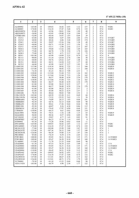
AP30A-42
17 455.22 MHz (10)
1 2 3 4 5 6 7 8 9
ALS00002 10 36.82 6.03 1.12 137 2 87.4 9/GR1ALS00003 10 37.47 5.60 0.76 132 2 87.4 9/GR2ARGNORT4 10 3.86 1.99 48 2 87.4ARGNORT5 10 3.24 2.89 47 2 87.4ATNBEAM1 10 14.87 1.83 0.68 39 2 87.4B CE311 10 3.04 2.06 174 2 87.4 8 9/GR7B CE312 10 3.44 2.09 174 2 87.4 8 9/GR9B CE411 10 3.86 1.38 49 2 87.4 8 9/GR7B CE412 10 3.57 1.56 52 2 87.4 8 9/GR9B CE511 10 2.42 2.15 107 2 87.4 8 9/GR7B NO611 10 2.86 1.69 165 1 87.4 8 9/GR8B NO711 10 3.54 1.78 126 1 87.4 8 9/GR8B NO811 10 2.37 1.65 73 1 87.4 8 9/GR8B SE911 10 2.22 0.79 62 2 87.4 8B SU111 10 2.76 1.06 50 2 87.4 8 9/GR6B SU112 10 2.47 1.48 56 2 87.4 8 9/GR9B SU211 0.80 10 3.22 1.37 60 2 87.4 8 9/GR6B SU212 10 3.27 1.92 59 2 87.4 8 9/GR9CAN01101 10 50.92 7.22 1.11 160 2 87.4 9/GR10CAN01201 10 50.92 7.22 1.11 160 2 87.4 9/GR10CAN01202 10 50.12 7.99 2.53 5 2 87.4CAN01203 10 51.04 7.53 1.26 162 2 87.4 9/GR12CAN01303 10 51.04 7.53 1.26 162 2 87.4 9/GR12CAN01304 10 50.48 8.59 2.54 178 2 87.4 9/GR13CAN01403 10 51.04 7.53 1.26 162 2 87.4 9/GR12CAN01404 10 50.48 8.59 2.54 178 2 87.4 9/GR13CAN01405 10 50.22 8.35 2.57 2 2 87.4 9/GR14CAN01504 10 50.48 8.59 2.54 178 2 87.4 9/GR13CAN01505 10 50.22 8.35 2.57 2 2 87.4 9/GR14CAN01605 10 50.22 8.35 2.57 2 2 87.4 9/GR14CAN01606 10 50.02 7.88 2.52 6 2 87.4CHLCONT4 10 2.21 0.69 68 2 87.4 9/GR16CHLCONT6 10 3.65 1.31 39 2 87.4 9/GR16CRBBAH01 10 24.13 1.83 0.68 141 1 87.4 9/GR18CRBBER01 10 32.13 0.60 0.60 90 1 87.4 9/GR18CRBBLZ01 10 17.26 0.64 0.64 90 1 87.4 9/GR18CRBEC001 10 8.26 4.20 0.86 115 1 87.4 9/GR18CRBJMC01 10 .45 17.97 0.99 0.68 151 1 87.4 9/GR18CTR00201 10 9.67 0.82 0.68 119 2 87.4EQAC0001 10 1.48 1.15 65 1 87.4 9/GR19EQAG0001 10 0.94 0.89 99 1 87.4 9/GR19GUY00302 10 4.77 1.43 0.85 91 2 87.4HNDIFRB2 10 15.16 1.14 0.85 8 1 87.4HTI00002 10 18.96 0.82 0.68 11 2 87.4HWA00002 10 36.82 6.03 1.12 137 2 87.4 9/GR1HWA00003 10 37.47 5.60 0.76 132 2 87.4 9/GR2MEX01NTE 80 10 25.99 2.88 2.07 155 2 87.4 1MEX02NTE 10 26.32 3.80 1.57 149 2 87.4 1MEX02SUR 10 19.88 3.19 1.87 158 2 87.4 1PRU00004 10 3.74 2.45 112 2 87.4PTRVIR01 10 36.31 8.26 3.55 171 2 87.4 1 6 9/GR20PTRVIR02 10 36.38 8.10 3.45 168 2 87.4 1 6 9/GR21TCA00001 10 21.53 0.60 0.60 90 2 87.4USAEH001 10 36.18 6.41 3.49 12 2 87.4 1 5 6USAEH002 10 36.31 8.26 3.55 171 2 87.4 1 6 9/GR20USAEH003 10 36.38 8.10 3.45 168 2 87.4 1 6 9/GR21USAEH004 10 36.21 8.20 3.12 165 2 87.4 1 5 6USAPSA02 10 36.82 6.03 1.12 137 2 87.4 9/GR1USAPSA03 10 37.47 5.60 0.76 132 2 87.4 9/GR2USAWH101 10 40.67 4.38 2.15 162 2 87.4USAWH102 10 40.71 3.74 1.79 149 2 87.4VCT00001 10 13.23 0.60 0.60 90 2 87.4VEN11VEN 10 6.90 2.50 1.77 122 2 87.4
- 660 -

AP30A-43
17 469.80 MHz (11)
1 2 3 4 5 6 7 8 9
ALS00002 11 36.86 6.04 1.11 137 1 87.4 9/GR1ALS00003 11 37.50 5.60 0.75 132 1 87.4 9/GR2ARGINSU4 11 3.40 0.68 19 1 87.4 9/GR3ARGINSU5 11 3.77 0.70 13 1 87.4 9/GR4ARGSUR04 11 3.32 1.50 40 1 87.4 9/GR3ARGSUR05 11 2.54 2.38 152 1 87.4 9/GR4ATGSJN01 11 17.07 0.60 0.60 90 1 87.4B CE311 11 3.04 2.06 174 1 87.4 8 9/GR7B CE312 11 3.44 2.09 174 1 87.4 8 9/GR9B CE411 11 3.86 1.38 49 1 87.4 8 9/GR7B CE412 11 3.57 1.56 52 1 87.4 8 9/GR9B CE511 11 2.44 2.13 104 1 87.4 8 9/GR7B NO611 11 1.62 2.85 1.69 165 2 87.4 8 9/GR8B NO711 11 3.54 1.78 126 2 87.4 8 9/GR8B NO811 11 2.37 1.65 73 2 87.4 8 9/GR8B SU111 11 2.76 1.05 50 1 87.4 8 9/GR6B SU112 11 2.47 1.48 56 1 87.4 8 9/GR9B SU211 11 3.22 1.36 60 1 87.4 8 9/GR6B SU212 11 3.20 1.96 58 1 87.4 8 9/GR9BERBERMU 11 32.32 0.60 0.60 90 2 87.4BOLAND01 11 6.49 2.57 87 1 87.4 9/GR5BOL00001 11 2.52 2.19 85 1 87.4BRB00001 11 12.93 0.60 0.60 90 2 87.4CAN01101 11 51.08 7.28 1.10 160 1 87.4 9/GR10CAN01201 11 51.08 7.28 1.10 160 1 87.4 9/GR10CAN01202 11 50.02 7.96 2.55 5 1 87.4CAN01203 11 51.08 7.47 1.26 162 1 87.4 9/GR12CAN01303 11 51.08 7.47 1.26 162 1 87.4 9/GR12CAN01304 11 50.48 8.58 2.54 178 1 87.4 9/GR13CAN01403 11 51.08 7.47 1.26 162 1 87.4 9/GR12CAN01404 11 50.48 8.58 2.54 178 1 87.4 9/GR13CAN01405 11 50.20 8.31 2.58 1 1 87.4 9/GR14CAN01504 11 50.48 8.58 2.54 178 1 87.4 9/GR13CAN01505 11 50.20 8.31 2.58 1 1 87.4 9/GR14CAN01605 11 50.20 8.31 2.58 1 1 87.4 9/GR14CAN01606 11 50.03 7.88 2.53 6 1 87.4CHLCONT5 11 2.60 0.68 55 1 87.4 9/GR17CHLPAC02 11 1.36 0.68 69 1 87.4 9/GR17CLMAND01 11 6.49 2.57 87 1 87.4 9/GR5CLM00001 11 5.87 3.98 1.96 118 1 87.4CUB00001 11 21.62 2.24 0.68 168 1 87.4EQACAND1 11 6.49 2.57 87 1 87.4 9/GR5EQAGAND1 11 6.49 2.57 87 1 87.4 9/GR5GRD00002 11 12.29 0.60 0.60 90 1 87.4GRD00059 11 12.29 0.60 0.60 90 1 87.4GRLDNK01 11 66.56 2.70 0.82 173 1 87.4 2GUY00201 11 4.78 1.44 0.85 95 1 87.4HWA00002 .20 11 36.86 6.04 1.11 137 1 87.4 9/GR1HWA00003 11 37.50 5.60 0.75 132 1 87.4 9/GR2MEX01NTE 11 26.01 2.89 2.08 155 1 87.4 1MEX01SUR 11 19.82 3.05 2.09 4 1 87.4 1MEX02NTE 11 26.31 3.84 1.55 148 1 87.4 1MEX02SUR 11 19.88 3.18 1.87 157 1 87.4 1PAQPAC01 11 0.60 0.60 90 1 87.4 9/GR17PRG00002 11 1.45 1.04 76 1 87.4PRUAND02 11 6.49 2.57 87 1 87.4 9/GR5PTRVIR01 11 36.32 8.24 3.56 171 1 87.4 1 6 9/GR20PTRVIR02 11 36.29 8.27 3.37 168 1 87.4 1 6 9/GR21URG00001 11 1.02 0.89 11 1 87.4USAEH001 11 36.17 6.42 3.49 12 1 87.4 1 5 6USAEH002 11 36.32 8.24 3.56 171 1 87.4 1 6 9/GR20USAEH003 11 36.29 8.27 3.37 168 1 87.4 1 6 9/GR21USAEH004 11 36.21 8.20 3.12 165 1 87.4 1 5 6USAPSA02 11 36.86 6.04 1.11 137 1 87.4 9/GR1USAPSA03 11 37.50 5.60 0.75 132 1 87.4 9/GR2USAWH101 11 40.68 4.36 2.15 162 1 87.4USAWH102 11 40.74 3.72 1.78 149 1 87.4VENAND03 11 6.49 2.57 87 1 87.4 9/GR5
- 661 -

AP30A-44
17 484.38 MHz (12)
1 2 3 4 5 6 7 8 9
ALS00002 12 36.82 6.03 1.12 137 2 87.4 9/GR1ALS00003 12 37.47 5.60 0.76 132 2 87.4 9/GR2ARGNORT4 12 3.86 1.99 48 2 87.4ARGNORT5 12 3.24 2.89 47 2 87.4B CE311 63.80 12 3.04 2.06 174 2 87.4 8 9/GR7B CE312 12 3.44 2.09 174 2 87.4 8 9/GR9B CE411 12 3.86 1.38 49 2 87.4 8 9/GR7B CE412 12 3.57 1.56 52 2 87.4 8 9/GR9B CE511 12 .11 2.42 2.15 107 2 87.4 8 9/GR7B NO611 12 2.86 1.69 165 1 87.4 8 9/GR8B NO711 12 3.54 1.78 126 1 87.4 8 9/GR8B NO811 12 2.37 1.65 73 1 87.4 8 9/GR8B SE911 12 2.22 0.79 62 2 87.4 8B SU111 12 2.76 1.06 50 2 87.4 8 9/GR6B SU112 12 2.47 1.48 56 2 87.4 8 9/GR9B SU211 12 3.22 1.37 60 2 87.4 8 9/GR6B SU212 12 3.27 1.92 59 2 87.4 8 9/GR9CAN01101 12 50.92 7.22 1.11 160 2 87.4 9/GR10CAN01201 12 50.92 7.22 1.11 160 2 87.4 9/GR10CAN01202 12 50.12 7.99 2.53 5 2 87.4CAN01203 12 51.04 7.53 1.26 162 2 87.4 9/GR12CAN01303 12 51.04 7.53 1.26 162 2 87.4 9/GR12CAN01304 12 50.48 8.58 2.54 178 2 87.4 9/GR13CAN01403 12 51.04 7.53 1.26 162 2 87.4 9/GR12CAN01404 12 50.48 8.59 2.54 178 2 87.4 9/GR13CAN01405 1.80 12 50.22 8.35 2.57 2 2 87.4 9/GR14CAN01504 12 50.48 8.59 2.54 178 2 87.4 9/GR13CAN01505 12 50.22 8.35 2.57 2 2 87.4 9/GR14CAN01605 12 50.22 8.35 2.57 2 2 87.4 9/GR14CAN01606 12 50.02 7.88 2.52 6 2 87.4CHLCONT4 12 2.21 0.69 68 2 87.4 9/GR16CHLCONT6 12 3.65 1.31 39 2 87.4 9/GR16CRBBAH01 12 24.13 1.83 0.68 141 1 87.4 9/GR18CRBBER01 12 32.13 0.60 0.60 90 1 87.4 9/GR18CRBBLZ01 12 17.26 0.64 0.64 90 1 87.4 9/GR18CRBEC001 12 8.26 4.20 0.86 115 1 87.4 9/GR18CRBJMC01 12 17.97 0.99 0.68 151 1 87.4 9/GR18CYM00001 12 19.57 0.60 0.60 90 2 87.4DOMIFRB2 12 18.79 0.98 0.69 167 2 87.4EQAC0001 12 1.48 1.15 65 1 87.4 9/GR19EQAG0001 12 0.94 0.89 99 1 87.4 9/GR19GUFMGG02 12 8.47 4.16 0.81 123 2 87.4 2 7HWA00002 12 36.82 6.03 1.12 137 2 87.4 9/GR1HWA00003 12 37.47 5.60 0.76 132 2 87.4 9/GR2JMC00005 12 18.12 0.60 0.60 90 2 87.4LCAIFRB1 12 13.90 0.60 0.60 90 2 87.4MEX01NTE 12 25.99 2.88 2.07 155 2 87.4 1MEX02NTE 12 26.32 3.80 1.57 149 2 87.4 1MEX02SUR 12 19.88 3.19 1.87 158 2 87.4 1PRU00004 12 3.74 2.45 112 2 87.4PTRVIR01 12 36.31 8.26 3.55 171 2 87.4 1 6 9/GR20PTRVIR02 12 36.38 8.10 3.45 168 2 87.4 1 6 9/GR21SLVIFRB2 12 13.59 0.60 0.60 90 1 87.4USAEH001 12 36.18 6.41 3.49 12 2 87.4 1 5 6USAEH002 12 36.31 8.26 3.55 171 2 87.4 1 6 9/GR20USAEH003 12 36.38 8.10 3.45 168 2 87.4 1 6 9/GR21USAEH004 12 36.21 8.20 3.12 165 2 87.4 1 5 6USAPSA02 12 36.82 6.03 1.12 137 2 87.4 9/GR1USAPSA03 12 37.47 5.60 0.76 132 2 87.4 9/GR2USAWH101 12 40.67 4.38 2.15 162 2 87.4USAWH102 12 40.71 3.74 1.79 149 2 87.4VEN11VEN 12 6.90 2.50 1.77 122 2 87.4
- 662 -

AP30A-45
17 498.96 MHz (13)
1 2 3 4 5 6 7 8 9
ALS00002 13 36.86 6.04 1.11 137 1 87.4 9/GR1ALS00003 13 37.50 5.60 0.75 132 1 87.4 9/GR2ARGINSU4 13 3.40 0.68 19 1 87.4 9/GR3ARGSUR04 13 3.32 1.50 40 1 87.4 9/GR3B CE311 13 3.04 2.06 174 1 87.4 8 9/GR7B CE312 13 3.44 2.09 174 1 87.4 8 9/GR9B CE411 13 3.86 1.38 49 1 87.4 8 9/GR7B CE412 13 3.57 1.56 52 1 87.4 8 9/GR9B CE511 13 2.44 2.13 104 1 87.4 8 9/GR7B NO611 13 2.85 1.69 165 2 87.4 8 9/GR8B NO711 13 3.54 1.78 126 2 87.4 8 9/GR8B NO811 13 2.37 1.65 73 2 87.4 8 9/GR8B SU111 13 2.76 1.05 50 1 87.4 8 9/GR6B SU112 13 2.47 1.48 56 1 87.4 8 9/GR9B SU211 13 3.22 1.36 60 1 87.4 8 9/GR6B SU212 13 3.20 1.96 58 1 87.4 8 9/GR9BAHIFRB1 13 24.16 1.81 0.70 142 1 87.4BERBERMU 13 32.32 0.60 0.60 90 2 87.4BERBER02 13 32.32 0.60 0.60 90 1 87.4 2 3BOLAND01 13 6.49 2.57 87 1 87.4 9/GR5CAN01101 13 51.08 7.28 1.10 160 1 87.4 9/GR10CAN01201 13 51.08 7.28 1.10 160 1 87.4 9/GR10CAN01202 13 50.02 7.96 2.55 5 1 87.4CAN01203 13 51.08 7.47 1.26 162 1 87.4 9/GR12CAN01303 13 51.08 7.47 1.26 162 1 87.4 9/GR12CAN01304 13 50.48 8.58 2.54 178 1 87.4 9/GR13CAN01403 13 51.08 7.47 1.26 162 1 87.4 9/GR12CAN01404 13 50.48 8.58 2.54 178 1 87.4 9/GR13CAN01405 13 50.20 8.31 2.58 1 1 87.4 9/GR14CAN01504 13 50.48 8.58 2.54 178 1 87.4 9/GR13CAN01505 13 50.20 8.31 2.58 1 1 87.4 9/GR14CAN01605 13 50.20 8.31 2.58 1 1 87.4 9/GR14CAN01606 13 50.03 7.88 2.53 6 1 87.4CHLCONT5 13 2.60 0.68 55 1 87.4 9/GR17CHLPAC02 13 1.36 0.68 69 1 87.4 9/GR17CLMAND01 13 6.49 2.57 87 1 87.4 9/GR5CLM00001 13 5.87 3.98 1.96 118 1 87.4EQACAND1 13 6.49 2.57 87 1 87.4 9/GR5EQAGAND1 13 6.49 2.57 87 1 87.4 9/GR5FLKANT01 13 3.54 0.68 12 1 87.4 2FLKFALKS 13 0.60 0.60 90 1 87.4 2 3GRD00002 13 12.29 0.60 0.60 90 1 87.4HWA00002 13 36.86 6.04 1.11 137 1 87.4 9/GR1HWA00003 13 37.50 5.60 0.75 132 1 87.4 9/GR2MEX01NTE 13 26.01 2.89 2.08 155 1 87.4 1MEX01SUR 13 19.82 3.05 2.09 4 1 87.4 1MEX02NTE 13 26.31 3.84 1.55 148 1 87.4 1MEX02SUR 13 19.88 3.18 1.87 157 1 87.4 1PAQPAC01 13 0.60 0.60 90 1 87.4 9/GR17PRG00002 13 1.45 1.04 76 1 87.4PRUAND02 13 6.49 2.57 87 1 87.4 9/GR5PTRVIR01 13 36.32 8.24 3.56 171 1 87.4 1 6 9/GR20PTRVIR02 13 36.29 8.27 3.37 168 1 87.4 1 6 9/GR21SPMFRAN3 13 47.51 3.16 0.79 7 1 87.4 2 7TRD00001 13 10.70 0.60 0.60 90 1 87.4URG00001 13 1.02 0.89 11 1 87.4USAEH001 13 36.17 6.42 3.49 12 1 87.4 1 5 6USAEH002 .20 13 36.32 8.24 3.56 171 1 87.4 1 6 9/GR20USAEH003 13 36.29 8.27 3.37 168 1 87.4 1 6 9/GR21USAEH004 13 36.21 8.20 3.12 165 1 87.4 1 5 6USAPSA02 13 36.86 6.04 1.11 137 1 87.4 9/GR1USAPSA03 20 13 37.50 5.60 0.75 132 1 87.4 9/GR2USAWH101 13 40.68 4.36 2.15 162 1 87.4USAWH102 13 40.74 3.72 1.78 149 1 87.4VENAND03 13 6.49 2.57 87 1 87.4 9/GR5VRG00001 13 18.48 0.60 0.60 90 1 87.4 4
- 663 -
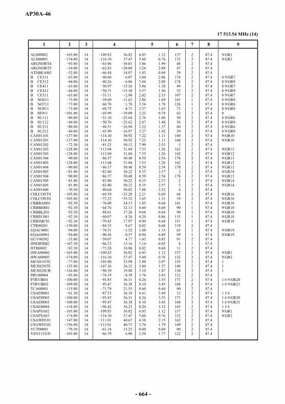
AP30A-46
17 513.54 MHz (14)
1 2 3 4 5 6 7 8 9
ALS00002 14 36.82 6.03 1.12 137 2 87.4 9/GR1ALS00003 14 37.47 5.60 0.76 132 2 87.4 9/GR2ARGNORT4 14 3.86 1.99 48 2 87.4ARGNORT5 14 3.24 2.89 47 2 87.4ATNBEAM1 14 14.87 1.83 0.68 39 2 87.4B CE311 14 3.04 2.06 174 2 87.4 8 9/GR7B CE312 14 3.44 2.09 174 2 87.4 8 9/GR9B CE411 14 3.86 1.38 49 2 87.4 8 9/GR7B CE412 14 3.57 1.56 52 2 87.4 8 9/GR9B CE511 14 2.42 2.15 107 2 87.4 8 9/GR7B NO611 14 2.86 1.69 165 1 87.4 8 9/GR8B NO711 14 3.54 1.78 126 1 87.4 8 9/GR8B NO811 14 2.37 1.65 73 1 87.4 8 9/GR8B SE911 14 2.22 0.79 62 2 87.4 8B SU111 14 2.76 1.06 50 2 87.4 8 9/GR6B SU112 14 2.47 1.48 56 2 87.4 8 9/GR9B SU211 14 3.22 1.37 60 2 87.4 8 9/GR6B SU212 14 3.27 1.92 59 2 87.4 8 9/GR9CAN01101 14 50.92 7.22 1.11 160 2 87.4 9/GR10CAN01201 14 50.92 7.22 1.11 160 2 87.4 9/GR10CAN01202 14 50.12 7.99 2.53 5 2 87.4CAN01203 14 51.04 7.53 1.26 162 2 87.4 9/GR12CAN01303 14 51.04 7.53 1.26 162 2 87.4 9/GR12CAN01304 14 50.48 8.59 2.54 178 2 87.4 9/GR13CAN01403 14 51.04 7.53 1.26 162 2 87.4 9/GR12CAN01404 14 50.48 8.59 2.54 178 2 87.4 9/GR13CAN01405 14 50.22 8.35 2.57 2 2 87.4 9/GR14CAN01504 14 50.48 8.59 2.54 178 2 87.4 9/GR13CAN01505 14 50.22 8.35 2.57 2 2 87.4 9/GR14CAN01605 14 50.22 8.35 2.57 2 2 87.4 9/GR14CAN01606 14 50.02 7.88 2.52 6 2 87.4CHLCONT4 14 2.21 0.69 68 2 87.4 9/GR16CHLCONT6 14 3.65 1.31 39 2 87.4 9/GR16CRBBAH01 14 24.13 1.83 0.68 141 1 87.4 9/GR18CRBBER01 14 32.13 0.60 0.60 90 1 87.4 9/GR18CRBBLZ01 14 17.26 0.64 0.64 90 1 87.4 9/GR18CRBEC001 14 8.26 4.20 0.86 115 1 87.4 9/GR18CRBJMC01 14 79.45 17.97 0.99 0.68 151 1 87.4 9/GR18CTR00201 14 9.67 0.82 0.68 119 2 87.4EQAC0001 14 1.48 1.15 65 1 87.4 9/GR19EQAG0001 14 0.94 0.89 99 1 87.4 9/GR19GUY00302 14 4.77 1.43 0.85 91 2 87.4HNDIFRB2 14 15.16 1.14 0.85 8 1 87.4HTI00002 14 18.96 0.82 0.68 11 2 87.4HWA00002 14 36.82 6.03 1.12 137 2 87.4 9/GR1HWA00003 14 37.47 5.60 0.76 132 2 87.4 9/GR2MEX01NTE 7.80 14 25.99 2.88 2.07 155 2 87.4 1MEX02NTE 14 26.32 3.80 1.57 149 2 87.4 1MEX02SUR 14 19.88 3.19 1.87 158 2 87.4 1PRU00004 14 3.74 2.45 112 2 87.4PTRVIR01 14 36.31 8.26 3.55 171 2 87.4 1 6 9/GR20PTRVIR02 14 36.38 8.10 3.45 168 2 87.4 1 6 9/GR21TCA00001 14 21.53 0.60 0.60 90 2 87.4USAEH001 14 36.18 6.41 3.49 12 2 87.4 1 5 6USAEH002 14 36.31 8.26 3.55 171 2 87.4 1 6 9/GR20USAEH003 14 36.38 8.10 3.45 168 2 87.4 1 6 9/GR21USAEH004 14 36.21 8.20 3.12 165 2 87.4 1 5 6USAPSA02 14 36.82 6.03 1.12 137 2 87.4 9/GR1USAPSA03 14 37.47 5.60 0.76 132 2 87.4 9/GR2USAWH101 14 40.67 4.38 2.15 162 2 87.4USAWH102 14 40.71 3.74 1.79 149 2 87.4VCT00001 14 13.23 0.60 0.60 90 2 87.4VEN11VEN 14 6.90 2.50 1.77 122 2 87.4
- 664 -
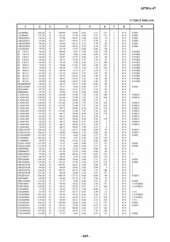
AP30A-47
17 528.12 MHz (15)
1 2 3 4 5 6 7 8 9
ALS00002 15 36.86 6.04 1.11 137 1 87.4 9/GR1ALS00003 15 37.50 5.60 0.75 132 1 87.4 9/GR2ARGINSU4 15 3.40 0.68 19 1 87.4 9/GR3ARGINSU5 15 3.77 0.70 13 1 87.4 9/GR4ARGSUR04 15 3.32 1.50 40 1 87.4 9/GR3ARGSUR05 15 2.54 2.38 152 1 87.4 9/GR4ATGSJN01 15 17.07 0.60 0.60 90 1 87.4B CE311 15 3.04 2.06 174 1 87.4 8 9/GR7B CE312 0 15 3.44 2.09 174 1 87.4 8 9/GR9B CE411 15 3.86 1.38 49 1 87.4 8 9/GR7B CE412 15 3.57 1.56 52 1 87.4 8 9/GR9B CE511 15 2.44 2.13 104 1 87.4 8 9/GR7B NO611 15 2.85 1.69 165 2 87.4 8 9/GR8B NO711 15 3.54 1.78 126 2 87.4 8 9/GR8B NO811 15 2.37 1.65 73 2 87.4 8 9/GR8B SU111 15 2.76 1.05 50 1 87.4 8 9/GR6B SU112 15 2.47 1.48 56 1 87.4 8 9/GR9B SU211 15 3.22 1.36 60 1 87.4 8 9/GR6B SU212 15 3.20 1.96 58 1 87.4 8 9/GR9BERBERMU 15 32.32 0.60 0.60 90 2 87.4BOLAND01 15 6.49 2.57 87 1 87.4 9/GR5BOL00001 15 2.52 2.19 85 1 87.4BRB00001 15 12.93 0.60 0.60 90 2 87.4CAN01101 15 51.08 7.28 1.10 160 1 87.4 9/GR10CAN01201 15 51.08 7.28 1.10 160 1 87.4 9/GR10CAN01202 15 50.02 7.96 2.55 5 1 87.4CAN01203 15 51.08 7.47 1.26 162 1 87.4 9/GR12CAN01303 15 51.08 7.47 1.26 162 1 87.4 9/GR12CAN01304 15 50.48 8.58 2.54 178 1 87.4 9/GR13CAN01403 15 51.08 7.47 1.26 162 1 87.4 9/GR12CAN01404 15 50.48 8.58 2.54 178 1 87.4 9/GR13CAN01405 15 50.20 8.31 2.58 1 1 87.4 9/GR14CAN01504 15 50.48 8.58 2.54 178 1 87.4 9/GR13CAN01505 15 50.20 8.31 2.58 1 1 87.4 9/GR14CAN01605 15 50.20 8.31 2.58 1 1 87.4 9/GR14CAN01606 15 50.03 7.88 2.53 6 1 87.4CHLCONT5 15 2.60 0.68 55 1 87.4 9/GR17CHLPAC02 15 1.36 0.68 69 1 87.4 9/GR17CLMAND01 15 6.49 2.57 87 1 87.4 9/GR5CLM00001 15 5.87 3.98 1.96 118 1 87.4CUB00001 15 21.62 2.24 0.68 168 1 87.4EQACAND1 15 6.49 2.57 87 1 87.4 9/GR5EQAGAND1 15 6.49 2.57 87 1 87.4 9/GR5GRD00002 15 12.29 0.60 0.60 90 1 87.4GRD00059 15 12.29 0.60 0.60 90 1 87.4GRLDNK01 15 66.56 2.70 0.82 173 1 87.4 2GUY00201 15 4.78 1.44 0.85 95 1 87.4HWA00002 66.20 15 36.86 6.04 1.11 137 1 87.4 9/GR1HWA00003 15 37.50 5.60 0.75 132 1 87.4 9/GR2MEX01NTE 15 26.01 2.89 2.08 155 1 87.4 1MEX01SUR 15 19.82 3.05 2.09 4 1 87.4 1MEX02NTE 15 26.31 3.84 1.55 148 1 87.4 1MEX02SUR 15 19.88 3.18 1.87 157 1 87.4 1PAQPAC01 15 0.60 0.60 90 1 87.4 9/GR17PRG00002 15 1.45 1.04 76 1 87.4PRUAND02 15 6.49 2.57 87 1 87.4 9/GR5PTRVIR01 15 36.32 8.24 3.56 171 1 87.4 1 6 9/GR20PTRVIR02 15 36.29 8.27 3.37 168 1 87.4 1 6 9/GR21URG00001 15 1.02 0.89 11 1 87.4USAEH001 15 36.17 6.42 3.49 12 1 87.4 1 5 6USAEH002 15 36.32 8.24 3.56 171 1 87.4 1 6 9/GR20USAEH003 15 36.29 8.27 3.37 168 1 87.4 1 6 9/GR21USAEH004 15 36.21 8.20 3.12 165 1 87.4 1 5 6USAPSA02 15 36.86 6.04 1.11 137 1 87.4 9/GR1USAPSA03 15 37.50 5.60 0.75 132 1 87.4 9/GR2USAWH101 15 40.68 4.36 2.15 162 1 87.4USAWH102 15 40.74 3.72 1.78 149 1 87.4VENAND03 15 6.49 2.57 87 1 87.4 9/GR5
- 665 -
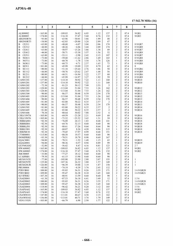
AP30A-48
17 542.70 MHz (16)
1 2 3 4 5 6 7 8 9
ALS00002 16 36.82 6.03 1.12 137 2 87.4 9/GR1ALS00003 16 37.47 5.60 0.76 132 2 87.4 9/GR2ARGNORT4 16 3.86 1.99 48 2 87.4ARGNORT5 16 3.24 2.89 47 2 87.4B CE311 16 3.04 2.06 174 2 87.4 8 9/GR7B CE312 16 3.44 2.09 174 2 87.4 8 9/GR9B CE411 16 3.86 1.38 49 2 87.4 8 9/GR7B CE412 16 3.57 1.56 52 2 87.4 8 9/GR9B CE511 16 53.11 2.42 2.15 107 2 87.4 8 9/GR7B NO611 16 2.86 1.69 165 1 87.4 8 9/GR8B NO711 16 3.54 1.78 126 1 87.4 8 9/GR8B NO811 16 2.37 1.65 73 1 87.4 8 9/GR8B SE911 16 9 2.22 0.79 62 2 87.4 8B SU111 16 2.76 1.06 50 2 87.4 8 9/GR6B SU112 16 2.47 1.48 56 2 87.4 8 9/GR9B SU211 16 3.22 1.37 60 2 87.4 8 9/GR6B SU212 16 3.27 1.92 59 2 87.4 8 9/GR9CAN01101 16 50.92 7.22 1.11 160 2 87.4 9/GR10CAN01201 16 50.92 7.22 1.11 160 2 87.4 9/GR10CAN01202 16 50.12 7.99 2.53 5 2 87.4CAN01203 16 51.04 7.53 1.26 162 2 87.4 9/GR12CAN01303 16 51.04 7.53 1.26 162 2 87.4 9/GR12CAN01304 16 50.48 8.59 2.54 178 2 87.4 9/GR13CAN01403 16 51.04 7.53 1.26 162 2 87.4 9/GR12CAN01404 16 50.48 8.59 2.54 178 2 87.4 9/GR13CAN01405 16 50.22 8.35 2.57 2 2 87.4 9/GR14CAN01504 16 50.48 8.59 2.54 178 2 87.4 9/GR13CAN01505 16 50.22 8.35 2.57 2 2 87.4 9/GR14CAN01605 16 50.22 8.35 2.57 2 2 87.4 9/GR14CAN01606 16 50.02 7.88 2.52 6 2 87.4CHLCONT4 16 2.21 0.69 68 2 87.4 9/GR16CHLCONT6 16 3.65 1.31 39 2 87.4 9/GR16CRBBAH01 16 24.13 1.83 0.68 141 1 87.4 9/GR18CRBBER01 16 32.13 0.60 0.60 90 1 87.4 9/GR18CRBBLZ01 16 17.26 0.64 0.64 90 1 87.4 9/GR18CRBEC001 16 8.26 4.20 0.86 115 1 87.4 9/GR18CRBJMC01 16 17.97 0.99 0.68 151 1 87.4 9/GR18CYM00001 16 19.57 0.60 0.60 90 2 87.4DOMIFRB2 16 18.79 0.98 0.69 167 2 87.4EQAC0001 16 1.48 1.15 65 1 87.4 9/GR19EQAG0001 16 0.94 0.89 99 1 87.4 9/GR19GUFMGG02 16 8.47 4.16 0.81 123 2 87.4 2 7HWA00002 16 36.82 6.03 1.12 137 2 87.4 9/GR1HWA00003 16 37.47 5.60 0.76 132 2 87.4 9/GR2JMC00005 16 18.12 0.60 0.60 90 2 87.4LCAIFRB1 16 13.90 0.60 0.60 90 2 87.4MEX01NTE 16 25.99 2.88 2.07 155 2 87.4 1MEX02NTE 16 26.32 3.80 1.57 149 2 87.4 1MEX02SUR 16 19.88 3.19 1.87 158 2 87.4 1PRU00004 16 3.74 2.45 112 2 87.4PTRVIR01 16 36.31 8.26 3.55 171 2 87.4 1 6 9/GR20PTRVIR02 16 36.38 8.10 3.45 168 2 87.4 1 6 9/GR21SLVIFRB2 16 13.59 0.60 0.60 90 1 87.4USAEH001 16 36.18 6.41 3.49 12 2 87.4 1 5 6USAEH002 16 36.31 8.26 3.55 171 2 87.4 1 6 9/GR20USAEH003 16 36.38 8.10 3.45 168 2 87.4 1 6 9/GR21USAEH004 16 36.21 8.20 3.12 165 2 87.4 1 5 6USAPSA02 16 36.82 6.03 1.12 137 2 87.4 9/GR1USAPSA03 16 37.47 5.60 0.76 132 2 87.4 9/GR2USAWH101 16 40.67 4.38 2.15 162 2 87.4USAWH102 16 40.71 3.74 1.79 149 2 87.4VEN11VEN 16 6.90 2.50 1.77 122 2 87.4
- 666 -
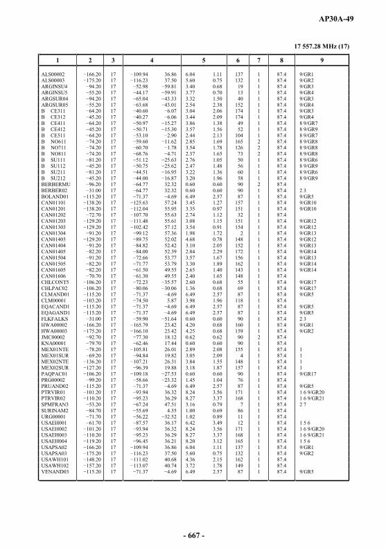
AP30A-49
17 557.28 MHz (17)
1 2 3 4 5 6 7 8 9
ALS00002 17 36.86 6.04 1.11 137 1 87.4 9/GR1ALS00003 0 17 37.50 5.60 0.75 132 1 87.4 9/GR2ARGINSU4 17 3.40 0.68 19 1 87.4 9/GR3ARGINSU5 17 3.77 0.70 13 1 87.4 9/GR4ARGSUR04 17 3.32 1.50 40 1 87.4 9/GR3ARGSUR05 17 .01 2.54 2.38 152 1 87.4 9/GR4B CE311 17 3.04 2.06 174 1 87.4 9/GR3B CE312 17 3.44 2.09 174 1 87.4 9/GR4B CE411 17 3.86 1.38 49 1 87.4 8 9/GR7B CE412 17 3.57 1.56 52 1 87.4 8 9/GR9B CE511 17 2.44 2.13 104 1 87.4 8 9/GR7B NO611 17 2.85 1.69 165 2 87.4 8 9/GR8B NO711 17 3.54 1.78 126 2 87.4 8 9/GR8B NO811 17 2.37 1.65 73 2 87.4 8 9/GR8B SU111 17 2.76 1.05 50 1 87.4 8 9/GR6B SU112 17 2.47 1.48 56 1 87.4 8 9/GR9B SU211 17 3.22 1.36 60 1 87.4 8 9/GR6B SU212 17 3.20 1.96 58 1 87.4 8 9/GR9BERBERMU 17 32.32 0.60 0.60 90 2 87.4BERBER02 17 32.32 0.60 0.60 90 1 87.4 2 3BOLAND01 17 6.49 2.57 87 1 87.4 9/GR5CAN01101 17 57.24 3.45 1.27 157 1 87.4 9/GR10CAN01201 17 55.95 3.35 0.97 151 1 87.4 9/GR10CAN01202 17 55.63 2.74 1.12 32 1 87.4CAN01203 17 55.61 3.08 1.15 151 1 87.4 9/GR12CAN01303 17 57.12 3.54 0.91 154 1 87.4 9/GR12CAN01304 17 57.36 1.98 1.72 2 1 87.4 9/GR13CAN01403 17 52.02 4.68 0.78 148 1 87.4 9/GR12CAN01404 17 52.42 3.10 2.05 152 1 87.4 9/GR13CAN01405 17 52.39 2.84 2.29 172 1 87.4 9/GR14CAN01504 17 53.77 3.57 1.67 156 1 87.4 9/GR13CAN01505 17 53.79 3.30 1.89 162 1 87.4 9/GR14CAN01605 17 49.55 2.65 1.40 143 1 87.4 9/GR14CAN01606 17 49.55 2.40 1.65 148 1 87.4CHLCONT5 17 2.60 0.68 55 1 87.4 9/GR17CHLPAC02 06.20 17 1.36 0.68 69 1 87.4 9/GR17CLMAND01 17 6.49 2.57 87 1 87.4 9/GR5CLM00001 17 5.87 3.98 1.96 118 1 87.4EQACAND1 17 6.49 2.57 87 1 87.4 9/GR5EQAGAND1 17 69 6.49 2.57 87 1 87.4 9/GR5FLKFALKS 17 0.60 0.60 90 1 87.4 2 3HWA00002 17 23.42 4.20 0.68 160 1 87.4 9/GR1HWA00003 17 23.42 4.25 0.68 159 1 87.4 9/GR2JMC00002 17 18.12 0.62 0.62 90 2 87.4KNA00001 17 17.44 0.60 0.60 90 1 87.4MEX01NTE 17 26.01 2.89 2.08 155 1 87.4 1MEX01SUR 17 19.82 3.05 2.09 4 1 87.4 1MEX02NTE 17 26.31 3.84 1.55 148 1 87.4 1MEX02SUR 17 .39 19.88 3.18 1.87 157 1 87.4 1PAQPAC01 17 0.60 0.60 90 1 87.4 9/GR17PRG00002 17 1.45 1.04 76 1 87.4PRUAND02 17 6.49 2.57 87 1 87.4 9/GR5PTRVIR01 17 36.32 8.24 3.56 171 1 87.4 1 6 9/GR20PTRVIR02 17 36.29 8.27 3.37 168 1 87.4 1 6 9/GR21SPMFRAN3 17 47.51 3.16 0.79 7 1 87.4 2 7SURINAM2 17 4.35 1.00 0.69 86 1 87.4URG00001 17 1.02 0.89 11 1 87.4USAEH001 17 36.17 6.42 3.49 12 1 87.4 1 5 6USAEH002 17 36.32 8.24 3.56 171 1 87.4 1 6 9/GR20USAEH003 17 36.29 8.27 3.37 168 1 87.4 1 6 9/GR21USAEH004 17 36.21 8.20 3.12 165 1 87.4 1 5 6USAPSA02 17 36.86 6.04 1.11 137 1 87.4 9/GR1USAPSA03 17 37.50 5.60 0.75 132 1 87.4 9/GR2USAWH101 17 40.68 4.36 2.15 162 1 87.4USAWH102 17 40.74 3.72 1.78 149 1 87.4VENAND03 17 6.49 2.57 87 1 87.4 9/GR5
- 667 -
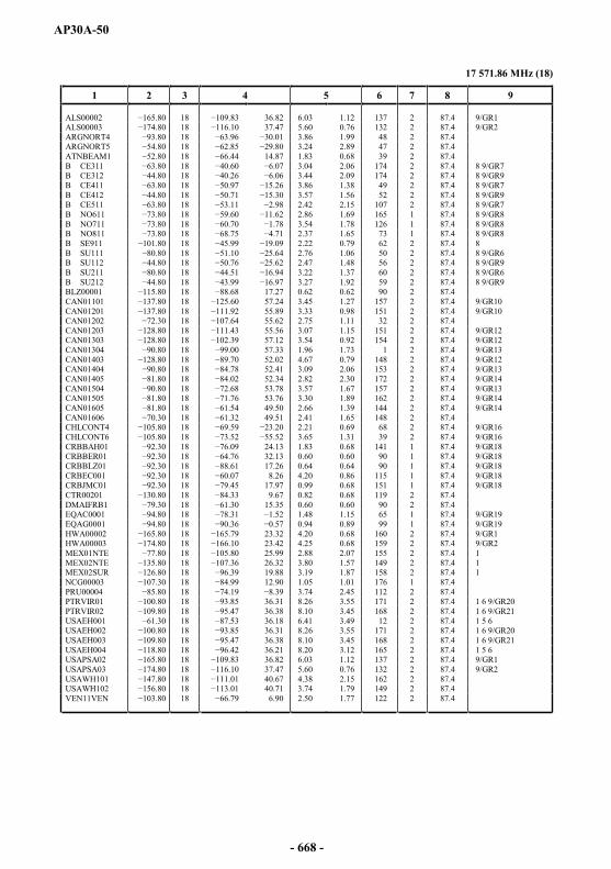
AP30A-50
17 571.86 MHz (18)
1 2 3 4 5 6 7 8 9
ALS00002 18 36.82 6.03 1.12 137 2 87.4 9/GR1ALS00003 18 37.47 5.60 0.76 132 2 87.4 9/GR2ARGNORT4 18 3.86 1.99 48 2 87.4ARGNORT5 18 3.24 2.89 47 2 87.4ATNBEAM1 18 14.87 1.83 0.68 39 2 87.4B CE311 18 3.04 2.06 174 2 87.4 8 9/GR7B CE312 18 3.44 2.09 174 2 87.4 8 9/GR9B CE411 18 5.26 3.86 1.38 49 2 87.4 8 9/GR7B CE412 18 3.57 1.56 52 2 87.4 8 9/GR9B CE511 18 2.42 2.15 107 2 87.4 8 9/GR7B NO611 18 2.86 1.69 165 1 87.4 8 9/GR8B NO711 18 3.54 1.78 126 1 87.4 8 9/GR8B NO811 18 2.37 1.65 73 1 87.4 8 9/GR8B SE911 18 2.22 0.79 62 2 87.4 8B SU111 18 2.76 1.06 50 2 87.4 8 9/GR6B SU112 18 2.47 1.48 56 2 87.4 8 9/GR9B SU211 18 3.22 1.37 60 2 87.4 8 9/GR6B SU212 18 3.27 1.92 59 2 87.4 8 9/GR9BLZ00001 18 17.27 0.62 0.62 90 2 87.4CAN01101 18 57.24 3.45 1.27 157 2 87.4 9/GR10CAN01201 37.80 18 55.89 3.33 0.98 151 2 87.4 9/GR10CAN01202 18 55.62 2.75 1.11 32 2 87.4CAN01203 18 55.56 3.07 1.15 151 2 87.4 9/GR12CAN01303 18 57.12 3.54 0.92 154 2 87.4 9/GR12CAN01304 18 00 57.33 1.96 1.73 1 2 87.4 9/GR13CAN01403 18 52.02 4.67 0.79 148 2 87.4 9/GR12CAN01404 18 52.41 3.09 2.06 153 2 87.4 9/GR13CAN01405 18 52.34 2.82 2.30 172 2 87.4 9/GR14CAN01504 18 53.78 3.57 1.67 157 2 87.4 9/GR13CAN01505 18 53.76 3.30 1.89 162 2 87.4 9/GR14CAN01605 18 49.50 2.66 1.39 144 2 87.4 9/GR14CAN01606 18 49.51 2.41 1.65 148 2 87.4CHLCONT4 18 2.21 0.69 68 2 87.4 9/GR16CHLCONT6 18 3.65 1.31 39 2 87.4 9/GR16CRBBAH01 18 24.13 1.83 0.68 141 1 87.4 9/GR18CRBBER01 18 32.13 0.60 0.60 90 1 87.4 9/GR18CRBBLZ01 18 17.26 0.64 0.64 90 1 87.4 9/GR18CRBEC001 18 8.26 4.20 0.86 115 1 87.4 9/GR18CRBJMC01 18 17.97 0.99 0.68 151 1 87.4 9/GR18CTR00201 18 9.67 0.82 0.68 119 2 87.4DMAIFRB1 18 15.35 0.60 0.60 90 2 87.4EQAC0001 18 1.48 1.15 65 1 87.4 9/GR19EQAG0001 18 0.94 0.89 99 1 87.4 9/GR19HWA00002 18 23.32 4.20 0.68 160 2 87.4 9/GR1HWA00003 18 23.42 4.25 0.68 159 2 87.4 9/GR2MEX01NTE 18 25.99 2.88 2.07 155 2 87.4 1MEX02NTE 18 26.32 3.80 1.57 149 2 87.4 1MEX02SUR 18 19.88 3.19 1.87 158 2 87.4 1NCG00003 18 12.90 1.05 1.01 176 1 87.4PRU00004 18 3.74 2.45 112 2 87.4PTRVIR01 18 36.31 8.26 3.55 171 2 87.4 1 6 9/GR20PTRVIR02 18 36.38 8.10 3.45 168 2 87.4 1 6 9/GR21USAEH001 18 36.18 6.41 3.49 12 2 87.4 1 5 6USAEH002 18 36.31 8.26 3.55 171 2 87.4 1 6 9/GR20USAEH003 0 18 36.38 8.10 3.45 168 2 87.4 1 6 9/GR21USAEH004 18 36.21 8.20 3.12 165 2 87.4 1 5 6USAPSA02 18 36.82 6.03 1.12 137 2 87.4 9/GR1USAPSA03 18 37.47 5.60 0.76 132 2 87.4 9/GR2USAWH101 18 40.67 4.38 2.15 162 2 87.4USAWH102 18 40.71 3.74 1.79 149 2 87.4VEN11VEN 18 6.90 2.50 1.77 122 2 87.4
- 668 -
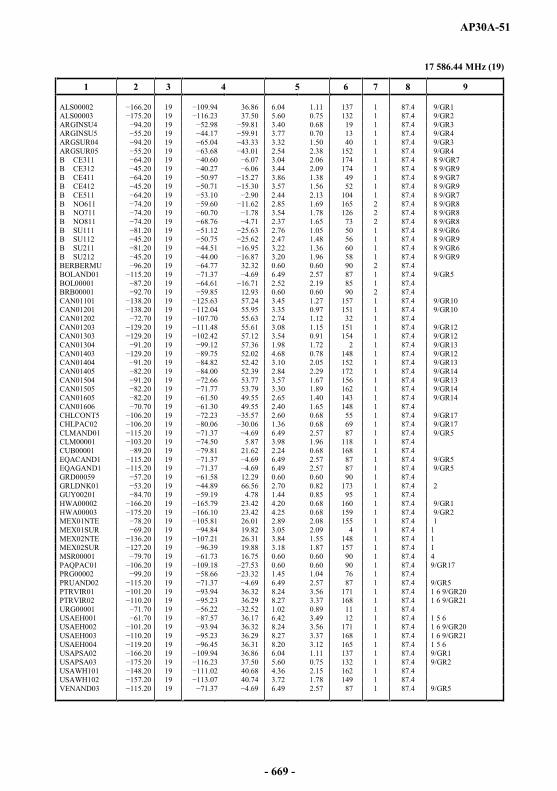
AP30A-51
17 586.44 MHz (19)
1 2 3 4 5 6 7 8 9
ALS00002 19 36.86 6.04 1.11 137 1 87.4 9/GR1ALS00003 19 37.50 5.60 0.75 132 1 87.4 9/GR2ARGINSU4 19 3.40 0.68 19 1 87.4 9/GR3ARGINSU5 19 3.77 0.70 13 1 87.4 9/GR4ARGSUR04 19 3.32 1.50 40 1 87.4 9/GR3ARGSUR05 19 2.54 2.38 152 1 87.4 9/GR4B CE311 19 3.04 2.06 174 1 87.4 8 9/GR7B CE312 19 3.44 2.09 174 1 87.4 8 9/GR9B CE411 19 3.86 1.38 49 1 87.4 8 9/GR7B CE412 19 0 3.57 1.56 52 1 87.4 8 9/GR9B CE511 19 2.44 2.13 104 1 87.4 8 9/GR7B NO611 19 2.85 1.69 165 2 87.4 8 9/GR8B NO711 19 3.54 1.78 126 2 87.4 8 9/GR8B NO811 19 2.37 1.65 73 2 87.4 8 9/GR8B SU111 19 2.76 1.05 50 1 87.4 8 9/GR6B SU112 19 2.47 1.48 56 1 87.4 8 9/GR9B SU211 19 3.22 1.36 60 1 87.4 8 9/GR6B SU212 19 3.20 1.96 58 1 87.4 8 9/GR9BERBERMU 19 32.32 0.60 0.60 90 2 87.4BOLAND01 19 6.49 2.57 87 1 87.4 9/GR5BOL00001 19 2.52 2.19 85 1 87.4BRB00001 19 12.93 0.60 0.60 90 2 87.4CAN01101 19 3 57.24 3.45 1.27 157 1 87.4 9/GR10CAN01201 19 55.95 3.35 0.97 151 1 87.4 9/GR10CAN01202 19 55.63 2.74 1.12 32 1 87.4CAN01203 19 55.61 3.08 1.15 151 1 87.4 9/GR12CAN01303 19 57.12 3.54 0.91 154 1 87.4 9/GR12CAN01304 19 57.36 1.98 1.72 2 1 87.4 9/GR13CAN01403 19 52.02 4.68 0.78 148 1 87.4 9/GR12CAN01404 19 52.42 3.10 2.05 152 1 87.4 9/GR13CAN01405 19 52.39 2.84 2.29 172 1 87.4 9/GR14CAN01504 19 53.77 3.57 1.67 156 1 87.4 9/GR13CAN01505 19 53.79 3.30 1.89 162 1 87.4 9/GR14CAN01605 19 49.55 2.65 1.40 143 1 87.4 9/GR14CAN01606 19 49.55 2.40 1.65 148 1 87.4CHLCONT5 19 2.60 0.68 55 1 87.4 9/GR17CHLPAC02 19 1.36 0.68 69 1 87.4 9/GR17CLMAND01 19 6.49 2.57 87 1 87.4 9/GR5CLM00001 19 5.87 3.98 1.96 118 1 87.4CUB00001 19 81 21.62 2.24 0.68 168 1 87.4EQACAND1 19 6.49 2.57 87 1 87.4 9/GR5EQAGAND1 19 6.49 2.57 87 1 87.4 9/GR5GRD00059 19 12.29 0.60 0.60 90 1 87.4GRLDNK01 19 66.56 2.70 0.82 173 1 87.4 2GUY00201 19 4.78 1.44 0.85 95 1 87.4HWA00002 19 23.42 4.20 0.68 160 1 87.4 9/GR1HWA00003 19 23.42 4.25 0.68 159 1 87.4 9/GR2MEX01NTE 19 26.01 2.89 2.08 155 1 87.4 1MEX01SUR 19 19.82 3.05 2.09 4 1 87.4 1MEX02NTE 19 26.31 3.84 1.55 148 1 87.4 1MEX02SUR 19 19.88 3.18 1.87 157 1 87.4 1MSR00001 19 16.75 0.60 0.60 90 1 87.4 4PAQPAC01 19 0.60 0.60 90 1 87.4 9/GR17PRG00002 19 1.45 1.04 76 1 87.4PRUAND02 19 6.49 2.57 87 1 87.4 9/GR5PTRVIR01 19 36.32 8.24 3.56 171 1 87.4 1 6 9/GR20PTRVIR02 19 36.29 8.27 3.37 168 1 87.4 1 6 9/GR21URG00001 19 1.02 0.89 11 1 87.4USAEH001 19 36.17 6.42 3.49 12 1 87.4 1 5 6USAEH002 19 36.32 8.24 3.56 171 1 87.4 1 6 9/GR20USAEH003 19 36.29 8.27 3.37 168 1 87.4 1 6 9/GR21USAEH004 19 36.31 8.20 3.12 165 1 87.4 1 5 6USAPSA02 19 36.86 6.04 1.11 137 1 87.4 9/GR1USAPSA03 19 37.50 5.60 0.75 132 1 87.4 9/GR2USAWH101 19 40.68 4.36 2.15 162 1 87.4USAWH102 19 40.74 3.72 1.78 149 1 87.4VENAND03 19 6.49 2.57 87 1 87.4 9/GR5
- 669 -
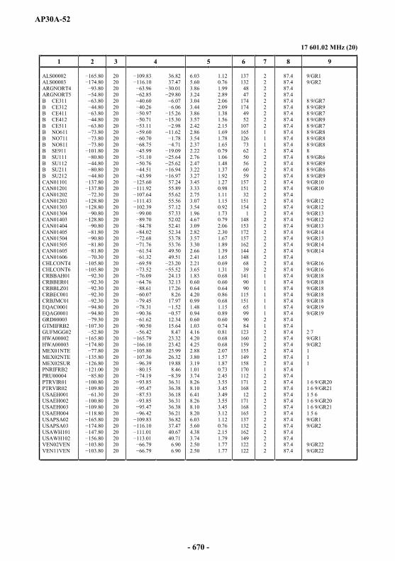
AP30A-52
17 601.02 MHz (20)
1 2 3 4 5 6 7 8 9
ALS00002 20 36.82 6.03 1.12 137 2 87.4 9/GR1ALS00003 20 37.47 5.60 0.76 132 2 87.4 9/GR2ARGNORT4 20 3.86 1.99 48 2 87.4ARGNORT5 20 3.24 2.89 47 2 87.4B CE311 20 3.04 2.06 174 2 87.4 8 9/GR7B CE312 20 3.44 2.09 174 2 87.4 8 9/GR9B CE411 20 3.86 1.38 49 2 87.4 8 9/GR7B CE412 20 3.57 1.56 52 2 87.4 8 9/GR9B CE511 20 2.42 2.15 107 2 87.4 8 9/GR7B NO611 20 2.86 1.69 165 1 87.4 8 9/GR8B NO711 20 .78 3.54 1.78 126 1 87.4 8 9/GR8B NO811 20 2.37 1.65 73 1 87.4 8 9/GR8B SE911 20 2.22 0.79 62 2 87.4 8B SU111 20 2.76 1.06 50 2 87.4 8 9/GR6B SU112 20 2.47 1.48 56 2 87.4 8 9/GR9B SU211 20 3.22 1.37 60 2 87.4 8 9/GR6B SU212 20 3.27 1.92 59 2 87.4 8 9/GR9CAN01101 20 57.24 3.45 1.27 157 2 87.4 9/GR10CAN01201 20 55.89 3.33 0.98 151 2 87.4 9/GR10CAN01202 20 55.62 2.75 1.11 32 2 87.4CAN01203 20 55.56 3.07 1.15 151 2 87.4 9/GR12CAN01303 20 57.12 3.54 0.92 154 2 87.4 9/GR12CAN01304 20 57.33 1.96 1.73 1 2 87.4 9/GR13CAN01403 20 52.02 4.67 0.79 148 2 87.4 9/GR12CAN01404 20 52.41 3.09 2.06 153 2 87.4 9/GR13CAN01405 20 52.34 2.82 2.30 172 2 87.4 9/GR14CAN01504 20 53.78 3.57 1.67 157 2 87.4 9/GR13CAN01505 20 53.76 3.30 1.89 162 2 87.4 9/GR14CAN01605 20 49.50 2.66 1.39 144 2 87.4 9/GR14CAN01606 20 49.51 2.41 1.65 148 2 87.4CHLCONT4 20 2.21 0.69 68 2 87.4 9/GR16CHLCONT6 20 3.65 1.31 39 2 87.4 9/GR16CRBBAH01 20 24.13 1.83 0.68 141 1 87.4 9/GR18CRBBER01 20 32.13 0.60 0.60 90 1 87.4 9/GR18CRBBLZ01 20 17.26 0.64 0.64 90 1 87.4 9/GR18CRBEC001 20 8.26 4.20 0.86 115 1 87.4 9/GR18CRBJMC01 20 17.97 0.99 0.68 151 1 87.4 9/GR18EQAC0001 20 1.48 1.15 65 1 87.4 9/GR19EQAG0001 20 0.94 0.89 99 1 87.4 9/GR19GRD00003 20 12.34 0.60 0.60 90 2 87.4GTMIFRB2 107.30 20 15.64 1.03 0.74 84 1 87.4GUFMGG02 20 8.47 4.16 0.81 123 2 87.4 2 7HWA00002 20 23.32 4.20 0.68 160 2 87.4 9/GR1HWA00003 20 23.42 4.25 0.68 159 2 87.4 9/GR2MEX01NTE 20 25.99 2.88 2.07 155 2 87.4 1MEX02NTE 20 26.32 3.80 1.57 149 2 87.4 1MEX02SUR 20 19.88 3.19 1.87 158 2 87.4 1PNRIFRB2 20 8.46 1.01 0.73 170 1 87.4PRU00004 20 3.74 2.45 112 2 87.4PTRVIR01 20 36.31 8.26 3.55 171 2 87.4 1 6 9/GR20PTRVIR02 20 36.38 8.10 3.45 168 2 87.4 1 6 9/GR21USAEH001 20 36.18 6.41 3.49 12 2 87.4 1 5 6USAEH002 20 36.31 8.26 3.55 171 2 87.4 1 6 9/GR20USAEH003 20 36.38 8.10 3.45 168 2 87.4 1 6 9/GR21USAEH004 20 36.21 8.20 3.12 165 2 87.4 1 5 6USAPSA02 20 36.82 6.03 1.12 137 2 87.4 9/GR1USAPSA03 20 37.47 5.60 0.76 132 2 87.4 9/GR2USAWH101 20 40.67 4.38 2.15 162 2 87.4USAWH102 20 40.71 3.74 1.79 149 2 87.4VEN02VEN 20 6.90 2.50 1.77 122 2 87.4 9/GR22VEN11VEN 20 6.90 2.50 1.77 122 2 87.4 9/GR22
- 670 -

AP30A-53
17 615.60 MHz (21)
1 2 3 4 5 6 7 8 9
ALS00002 21 36.86 6.04 1.11 137 1 87.4 9/GR1ALS00003 21 37.50 5.60 0.75 132 1 87.4 9/GR2ARGINSU4 21 3.40 0.68 19 1 87.4 9/GR3ARGINSU5 21 3.77 0.70 13 1 87.4 9/GR4ARGSUR04 21 3.32 1.50 40 1 87.4 9/GR3ARGSUR05 21 2.54 2.38 152 1 87.4 9/GR4B CE311 21 3.04 2.06 174 1 87.4 8 9/GR7B CE312 21 3.44 2.09 174 1 87.4 8 9/GR9B CE411 20 21 3.86 1.38 49 1 87.4 8 9/GR7B CE412 21 3.57 1.56 52 1 87.4 8 9/GR9B CE511 21 2.44 2.13 104 1 87.4 8 9/GR7B NO611 21 2.85 1.69 165 2 87.4 8 9/GR8B NO711 21 0 3.54 1.78 126 2 87.4 8 9/GR8B NO811 21 2.37 1.65 73 2 87.4 8 9/GR8B SU111 21 2.76 1.05 50 1 87.4 8 9/GR6B SU112 21 2.47 1.48 56 1 87.4 8 9/GR9B SU211 21 3.22 1.36 60 1 87.4 8 9/GR6B SU212 21 3.20 1.96 58 1 87.4 8 9/GR9BERBERMU 21 32.32 0.60 0.60 90 2 87.4BOLAND01 21 6.49 2.57 87 1 87.4 9/GR5CAN01101 21 57.24 3.45 1.27 157 1 87.4 9/GR10CAN01201 21 55.95 3.35 0.97 151 1 87.4 9/GR10CAN01202 21 55.63 2.74 1.12 32 1 87.4CAN01203 21 55.61 3.08 1.15 151 1 87.4 9/GR12CAN01303 21 57.12 3.54 0.91 154 1 87.4 9/GR12CAN01304 21 57.36 1.98 1.72 2 1 87.4 9/GR13CAN01403 21 52.02 4.68 0.78 148 1 87.4 9/GR12CAN01404 21 52.42 3.10 2.05 152 1 87.4 9/GR13CAN01405 21 52.39 2.84 2.29 172 1 87.4 9/GR14CAN01504 21 53.77 3.57 1.67 156 1 87.4 9/GR13CAN01505 21 53.79 3.30 1.89 162 1 87.4 9/GR14CAN01605 21 49.55 2.65 1.40 143 1 87.4 9/GR14CAN01606 21 49.55 2.40 1.65 148 1 87.4CHLCONT5 21 2.60 0.68 55 1 87.4 9/GR17CHLPAC02 21 1.36 0.68 69 1 87.4 9/GR17CLMAND01 21 6.49 2.57 87 1 87.4 9/GR5CLM00001 21 5.87 3.98 1.96 118 1 87.4EQACAND1 21 6.49 2.57 87 1 87.4 9/GR5EQAGAND1 21 6.49 2.57 87 1 87.4 9/GR5HWA00002 21 23.42 4.20 0.68 160 1 87.4 9/GR1HWA00003 21 23.42 4.25 0.68 159 1 87.4 9/GR2JMC00002 21 18.12 0.62 0.62 90 2 87.4KNA00001 9.70 21 17.44 0.60 0.60 90 1 87.4MEX01NTE 21 26.01 2.89 2.08 155 1 87.4 1MEX01SUR 21 19.82 3.05 2.09 4 1 87.4 1MEX02NTE 21 26.31 3.84 1.55 148 1 87.4 1MEX02SUR 21 19.88 3.18 1.87 157 1 87.4 1PAQPAC01 21 0.60 0.60 90 1 87.4 9/GR17PRG00002 21 1.45 1.04 76 1 87.4PRUAND02 21 6.49 2.57 87 1 87.4 9/GR5PTRVIR01 21 36.32 8.24 3.56 171 1 87.4 1 6 9/GR20PTRVIR02 21 36.29 8.27 3.37 168 1 87.4 1 6 9/GR21SPMFRAN3 21 47.51 3.16 0.79 7 1 87.4 2 7SURINAM2 21 4.35 1.00 0.69 86 1 87.4URG00001 21 1.02 0.89 11 1 87.4USAEH001 21 36.17 6.42 3.49 12 1 87.4 1 5 6USAEH002 21 36.32 8.24 3.56 171 1 87.4 1 6 9/GR20USAEH003 21 36.29 8.27 3.37 168 1 87.4 1 6 9/GR21USAEH004 21 36.21 8.20 3.12 165 1 87.4 1 5 6USAPSA02 21 36.86 6.04 1.11 137 1 87.4 9/GR1USAPSA03 21 37.50 5.60 0.75 132 1 87.4 9/GR2USAWH101 21 40.68 4.36 2.15 162 1 87.4USAWH102 21 40.74 3.72 1.78 149 1 87.4VENAND03 21 6.49 2.57 87 1 87.4 9/GR5
- 671 -
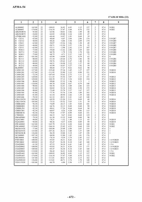
AP30A-54
17 630.18 MHz (22)
1 2 3 4 5 6 7 8 9
ALS00002 22 36.82 6.03 1.12 137 2 87.4 9/GR1ALS00003 22 37.47 5.60 0.76 132 2 87.4 9/GR2ARGNORT4 22 3.86 1.99 48 2 87.4ARGNORT5 22 85 3.24 2.89 47 2 87.4ATNBEAM1 22 14.87 1.83 0.68 39 2 87.4B CE311 22 3.04 2.06 174 2 87.4 8 9/GR7B CE312 22 3.44 2.09 174 2 87.4 8 9/GR9B CE411 22 3.86 1.38 49 2 87.4 8 9/GR7B CE412 22 3.57 1.56 52 2 87.4 8 9/GR9B CE511 22 2.42 2.15 107 2 87.4 8 9/GR7B NO611 22 2.86 1.69 165 1 87.4 8 9/GR8B NO711 22 3.54 1.78 126 1 87.4 8 9/GR8B NO811 22 2.37 1.65 73 1 87.4 8 9/GR8B SE911 22 2.22 0.79 62 2 87.4 8B SU111 22 2.76 1.06 50 2 87.4 8 9/GR6B SU112 22 2.47 1.48 56 2 87.4 8 9/GR9B SU211 22 3.22 1.37 60 2 87.4 8 9/GR6B SU212 22 3.27 1.92 59 2 87.4 8 9/GR9BLZ00001 22 17.27 0.62 0.62 90 2 87.4CAN01101 22 57.24 3.45 1.27 157 2 87.4 9/GR10CAN01201 22 55.89 3.33 0.98 151 2 87.4 9/GR10CAN01202 22 55.62 2.75 1.11 32 2 87.4CAN01203 22 55.56 3.07 1.15 151 2 87.4 9/GR12CAN01303 22 57.12 3.54 0.92 154 2 87.4 9/GR12CAN01304 22 57.33 1.96 1.73 1 2 87.4 9/GR13CAN01403 22 52.02 4.67 0.79 148 2 87.4 9/GR12CAN01404 22 52.41 3.09 2.06 153 2 87.4 9/GR13CAN01405 22 52.34 2.82 2.30 172 2 87.4 9/GR14CAN01504 22 53.78 3.57 1.67 157 2 87.4 9/GR13CAN01505 22 53.76 3.30 1.89 162 2 87.4 9/GR14CAN01605 22 49.50 2.66 1.39 144 2 87.4 9/GR14CAN01606 22 49.51 2.41 1.65 148 2 87.4CHLCONT4 22 2.21 0.69 68 2 87.4 9/GR16CHLCONT6 .80 22 3.65 1.31 39 2 87.4 9/GR16CRBBAH01 22 24.13 1.83 0.68 141 1 87.4 9/GR18CRBBER01 22 32.13 0.60 0.60 90 1 87.4 9/GR18CRBBLZ01 22 17.26 0.64 0.64 90 1 87.4 9/GR18CRBEC001 22 8.26 4.20 0.86 115 1 87.4 9/GR18CRBJMC01 22 17.97 0.99 0.68 151 1 87.4 9/GR18CTR00201 22 9.67 0.82 0.68 119 2 87.4DMAIFRB1 22 15.35 0.60 0.60 90 2 87.4EQAC0001 22 1.48 1.15 65 1 87.4 9/GR19EQAG0001 22 0.94 0.89 99 1 87.4 9/GR19HWA00002 22 23.32 4.20 0.68 160 2 87.4 9/GR1HWA00003 22 23.42 4.25 0.68 159 2 87.4 9/GR2MEX01NTE 22 25.99 2.88 2.07 155 2 87.4 1MEX02NTE 22 26.32 3.80 1.57 149 2 87.4 1MEX02SUR 22 19.88 3.19 1.87 158 2 87.4 1NCG00003 22 12.90 1.05 1.01 176 1 87.4PRU00004 22 3.74 2.45 112 2 87.4PTRVIR01 22 36.31 8.26 3.55 171 2 87.4 1 6 9/GR20PTRVIR02 22 36.38 8.10 3.45 168 2 87.4 1 6 9/GR21USAEH001 22 36.18 6.41 3.49 12 2 87.4 1 5 6USAEH002 22 36.31 8.26 3.55 171 2 87.4 1 6 9/GR20USAEH003 22 36.38 8.10 3.45 168 2 87.4 1 6 9/GR21USAEH004 22 36.21 8.20 3.12 165 2 87.4 1 5 6USAPSA02 22 36.82 6.03 1.12 137 2 87.4 9/GR1USAPSA03 22 37.47 5.60 0.76 132 2 87.4 9/GR2USAWH101 22 40.67 4.38 2.15 162 2 87.4USAWH102 22 40.71 3.74 1.79 149 2 87.4VEN11VEN 22 6.90 2.50 1.77 122 2 87.4
- 672 -

AP30A-55
17 644.76 MHz (23)
1 2 3 4 5 6 7 8 9
ALS00002 23 36.86 6.04 1.11 137 1 87.4 9/GR1ALS00003 23 23 37.50 5.60 0.75 132 1 87.4 9/GR2ARGINSU4 23 3.40 0.68 19 1 87.4 9/GR3ARGINSU5 23 3.77 0.70 13 1 87.4 9/GR4ARGSUR04 23 3.32 1.50 40 1 87.4 9/GR3ARGSUR05 23 2.54 2.38 152 1 87.4 9/GR4B CE311 23 3.04 2.06 174 1 87.4 8 9/GR7B CE312 23 3.44 2.09 174 1 87.4 8 9/GR9B CE411 23 3.86 1.38 49 1 87.4 8 9/GR7B CE412 23 3.57 1.56 52 1 87.4 8 9/GR9B CE511 23 2.44 2.13 104 1 87.4 8 9/GR7B NO611 23 2.85 1.69 165 2 87.4 8 9/GR8B NO711 23 3.54 1.78 126 2 87.4 8 9/GR8B NO811 23 2.37 1.65 73 2 87.4 8 9/GR8B SU111 23 2.76 1.05 50 1 87.4 8 9/GR6B SU112 23 2.47 1.48 56 1 87.4 8 9/GR9B SU211 23 3.22 1.36 60 1 87.4 8 9/GR6B SU212 23 3.20 1.96 58 1 87.4 8 9/GR9BERBERMU 0 23 32.32 0.60 0.60 90 2 87.4BOLAND01 23 6.49 2.57 87 1 87.4 9/GR5BOL00001 23 2.52 2.19 85 1 87.4BRB00001 23 12.93 0.60 0.60 90 2 87.4CAN01101 23 57.24 3.45 1.27 157 1 87.4 9/GR10CAN01201 23 55.95 3.35 0.97 151 1 87.4 9/GR10CAN01202 23 55.63 2.74 1.12 32 1 87.4CAN01203 23 55.61 3.08 1.15 151 1 87.4 9/GR12CAN01303 23 57.12 3.54 0.91 154 1 87.4 9/GR12CAN01304 23 57.36 1.98 1.72 2 1 87.4 9/GR13CAN01403 23 52.02 4.68 0.78 148 1 87.4 9/GR12CAN01404 23 52.42 3.10 2.05 152 1 87.4 9/GR13CAN01405 23 52.39 2.84 2.29 172 1 87.4 9/GR14CAN01504 23 53.77 3.57 1.67 156 1 87.4 9/GR13CAN01505 23 53.79 3.30 1.89 162 1 87.4 9/GR14CAN01605 23 49.55 2.65 1.40 143 1 87.4 9/GR14CAN01606 23 49.55 2.40 1.65 148 1 87.4CHLCONT5 23 2.60 0.68 55 1 87.4 9/GR17CHLPAC02 23 1.36 0.68 69 1 87.4 9/GR17CLMAND01 23 6.49 2.57 87 1 87.4 9/GR5CLM00001 23 5.87 3.98 1.96 118 1 87.4CUB00001 23 21.62 2.24 0.68 168 1 87.4EQACAND1 23 6.49 2.57 87 1 87.4 9/GR5EQAGAND1 23 6.49 2.57 87 1 87.4 9/GR5GRD00059 23 12.29 0.60 0.60 90 1 87.4GRLDNK01 23 66.56 2.70 0.82 173 1 87.4 2GUY00201 23 4.78 1.44 0.85 95 1 87.4HWA00002 23 23.42 4.20 0.68 160 1 87.4 9/GR1HWA00003 23 23.42 4.25 0.68 159 1 87.4 9/GR2MEX01NTE 23 26.01 2.89 2.08 155 1 87.4 1MEX01SUR 23 19.82 3.05 2.09 4 1 87.4 1MEX02NTE 23 26.31 3.84 1.55 148 1 87.4 1MEX02SUR 23 19.88 3.18 1.87 157 1 87.4 1MSR00001 23 16.75 0.60 0.60 90 1 87.4 4PAQPAC01 23 0.60 0.60 90 1 87.4 9/GR17PRG00002 23 1.45 1.04 76 1 87.4PRUAND02 23 6.49 2.57 87 1 87.4 9/GR5PTRVIR01 23 36.32 8.24 3.56 171 1 87.4 1 6 9/GR20PTRVIR02 23 36.29 8.27 3.37 168 1 87.4 1 6 9/GR21URG00001 23 1.02 0.89 11 1 87.4USAEH001 23 36.17 6.42 3.49 12 1 87.4 1 5 6USAEH002 23 36.32 8.24 3.56 171 1 87.4 1 6 9/GR20USAEH003 23 36.29 8.27 3.37 168 1 87.4 1 6 9/GR21USAEH004 23 5 36.21 8.20 3.12 165 1 87.4 1 5 6USAPSA02 23 36.86 6.04 1.11 137 1 87.4 9/GR1USAPSA03 23 37.50 5.60 0.75 132 1 87.4 9/GR2USAWH101 23 40.68 4.36 2.15 162 1 87.4USAWH102 23 40.74 3.72 1.78 149 1 87.4VENAND03 23 6.49 2.57 87 1 87.4 9/GR5
- 673 -

AP30A-56
17 659.34 MHz (24)
1 2 3 4 5 6 7 8 9
ALS00002 24 36.82 6.03 1.12 137 2 87.4 9/GR1ALS00003 24 37.47 5.60 0.76 132 2 87.4 9/GR2ARGNORT4 80 24 3.86 1.99 48 2 87.4ARGNORT5 24 3.24 2.89 47 2 87.4B CE311 24 3.04 2.06 174 2 87.4 8 9/GR7B CE312 24 3.44 2.09 174 2 87.4 8 9/GR9B CE411 24 3.86 1.38 49 2 87.4 8 9/GR7B CE412 24 3.57 1.56 52 2 87.4 8 9/GR9B CE511 24 2.42 2.15 107 2 87.4 8 9/GR7B NO611 24 2.86 1.69 165 1 87.4 8 9/GR8B NO711 24 3.54 1.78 126 1 87.4 8 9/GR8B NO811 24 2.37 1.65 73 1 87.4 8 9/GR8B SE911 24 2.22 0.79 62 2 87.4 8B SU111 24 2.76 1.06 50 2 87.4 8 9/GR6B SU112 24 2.47 1.48 56 2 87.4 8 9/GR9B SU211 24 3.22 1.37 60 2 87.4 8 9/GR6B SU212 24 3.27 1.92 59 2 87.4 8 9/GR9CAN01101 24 57.24 3.45 1.27 157 2 87.4 9/GR10CAN01201 24 55.89 3.33 0.98 151 2 87.4 9/GR10CAN01202 30 24 55.62 2.75 1.11 32 2 87.4CAN01203 24 55.56 3.07 1.15 151 2 87.4 9/GR12CAN01303 24 57.12 3.54 0.92 154 2 87.4 9/GR12CAN01304 24 57.33 1.96 1.73 1 2 87.4 9/GR13CAN01403 24 52.02 4.67 0.79 148 2 87.4 9/GR12CAN01404 24 52.41 3.09 2.06 153 2 87.4 9/GR13CAN01405 24 52.34 2.82 2.30 172 2 87.4 9/GR14CAN01504 24 53.78 3.57 1.67 157 2 87.4 9/GR13CAN01505 24 53.76 3.30 1.89 162 2 87.4 9/GR14CAN01605 24 49.50 2.66 1.39 144 2 87.4 9/GR14CAN01606 24 49.51 2.41 1.65 148 2 87.4CHLCONT4 24 2.21 0.69 68 2 87.4 9/GR16CHLCONT6 24 3.65 1.31 39 2 87.4 9/GR16CRBBAH01 24 24.13 1.83 0.68 141 1 87.4 9/GR18CRBBER01 24 32.13 0.60 0.60 90 1 87.4 9/GR18CRBBLZ01 24 17.26 0.64 0.64 90 1 87.4 9/GR18CRBEC001 24 8.26 4.20 0.86 115 1 87.4 9/GR18CRBJMC01 92.30 24 17.97 0.99 0.68 151 1 87.4 9/GR18EQAC0001 24 1.48 1.15 65 1 87.4 9/GR19EQAG0001 24 0.94 0.89 99 1 87.4 9/GR19GRD00003 24 12.34 0.60 0.60 90 2 87.4GTMIFRB2 24 15.64 1.03 0.74 84 1 87.4GUFMGG02 24 8.47 4.16 0.81 123 2 87.4 2 7HWA00002 24 23.32 4.20 0.68 160 2 87.4 9/GR1HWA00003 24 23.42 4.25 0.68 159 2 87.4 9/GR2MEX01NTE 24 25.99 2.88 2.07 155 2 87.4 1MEX02NTE 24 26.32 3.80 1.57 149 2 87.4 1MEX02SUR 24 19.88 3.19 1.87 158 2 87.4 1PNRIFRB2 24 8.46 1.01 0.73 170 1 87.4PRU00004 24 3.74 2.45 112 2 87.4PTRVIR01 24 5 36.31 8.26 3.55 171 2 87.4 1 6 9/GR20PTRVIR02 24 36.38 8.10 3.45 168 2 87.4 1 6 9/GR21USAEH001 24 36.18 6.41 3.49 12 2 87.4 1 5 6USAEH002 24 36.31 8.26 3.55 171 2 87.4 1 6 9/GR20USAEH003 24 47 36.38 8.10 3.45 168 2 87.4 1 6 9/GR21USAEH004 24 36.21 8.20 3.12 165 2 87.4 1 5 6USAPSA02 24 36.82 6.03 1.12 137 2 87.4 9/GR1USAPSA03 24 37.47 5.60 0.76 132 2 87.4 9/GR2USAWH101 24 40.67 4.38 2.15 162 2 87.4USAWH102 24 40.71 3.74 1.79 149 2 87.4VEN02VEN 24 6.90 2.50 1.77 122 2 87.4 9/GR22VEN11VEN 24 6.90 2.50 1.77 122 2 87.4 9/GR22
- 674 -

AP30A-57
17 673.92 MHz (25)
1 2 3 4 5 6 7 8 9
ALS00002 25 36.86 6.04 1.11 137 1 87.4 9/GR1ALS00003 25 37.50 5.60 0.75 132 1 87.4 9/GR2ARGINSU4 25 3.40 0.68 19 1 87.4 9/GR3ARGINSU5 25 3.77 0.70 13 1 87.4 9/GR4ARGSUR04 25 65.04 3.32 1.50 40 1 87.4 9/GR3ARGSUR05 25 2.54 2.38 152 1 87.4 9/GR4B CE311 25 3.04 2.06 174 1 87.4 8 9/GR7B CE312 25 3.44 2.09 174 1 87.4 8 9/GR9B CE411 25 3.86 1.38 49 1 87.4 8 9/GR7B CE412 25 3.57 1.56 52 1 87.4 8 9/GR9B CE511 25 2.44 2.13 104 1 87.4 8 9/GR7B NO611 25 2.85 1.69 165 2 87.4 8 9/GR8B NO711 25 3.54 1.78 126 2 87.4 8 9/GR8B NO811 25 2.37 1.65 73 2 87.4 8 9/GR8B SU111 25 2.76 1.05 50 1 87.4 8 9/GR6B SU112 25 2.47 1.48 56 1 87.4 8 9/GR9B SU211 25 3.22 1.36 60 1 87.4 8 9/GR6B SU212 25 3.20 1.96 58 1 87.4 8 9/GR9BERBERMU 25 32.32 0.60 0.60 90 2 87.4BOLAND01 25 6.49 2.57 87 1 87.4 9/GR5CAN01101 25 57.24 3.45 1.27 157 1 87.4 9/GR10CAN01201 20 25 55.95 3.35 0.97 151 1 87.4 9/GR10CAN01202 25 55.63 2.74 1.12 32 1 87.4CAN01203 25 55.61 3.08 1.15 151 1 87.4 9/GR12CAN01303 25 57.12 3.54 0.91 154 1 87.4 9/GR12CAN01304 25 57.36 1.98 1.72 2 1 87.4 9/GR13CAN01403 25 52.02 4.68 0.78 148 1 87.4 9/GR12CAN01404 25 52.42 3.10 2.05 152 1 87.4 9/GR13CAN01405 25 52.39 2.84 2.29 172 1 87.4 9/GR14CAN01504 25 53.77 3.57 1.67 156 1 87.4 9/GR13CAN01505 25 53.79 3.30 1.89 162 1 87.4 9/GR14CAN01605 25 49.55 2.65 1.40 143 1 87.4 9/GR14CAN01606 25 49.55 2.40 1.65 148 1 87.4CHLCONT5 25 2.60 0.68 55 1 87.4 9/GR17CHLPAC02 25 1.36 0.68 69 1 87.4 9/GR17CLMAND01 25 6.49 2.57 87 1 87.4 9/GR5CLM00001 25 5.87 3.98 1.96 118 1 87.4EQACAND1 25 6.49 2.57 87 1 87.4 9/GR5EQAGAND1 20 25 6.49 2.57 87 1 87.4 9/GR5HWA00002 25 23.42 4.20 0.68 160 1 87.4 9/GR1HWA00003 25 23.42 4.25 0.68 159 1 87.4 9/GR2JMC00002 25 18.12 0.62 0.62 90 2 87.4KNA00001 25 17.44 0.60 0.60 90 1 87.4MEX01NTE 25 26.01 2.89 2.08 155 1 87.4 1MEX01SUR 25 19.82 3.05 2.09 4 1 87.4 1MEX02NTE 25 26.31 3.84 1.55 148 1 87.4 1MEX02SUR 25 19.88 3.18 1.87 157 1 87.4 1PAQPAC01 25 0.60 0.60 90 1 87.4 9/GR17PRG00002 25 1.45 1.04 76 1 87.4PRUAND02 25 6.49 2.57 87 1 87.4 9/GR5PTRVIR01 25 36.32 8.24 3.56 171 1 87.4 1 6 9/GR20PTRVIR02 25 36.29 8.27 3.37 168 1 87.4 1 6 9/GR21SPMFRAN3 25 47.51 3.16 0.79 7 1 87.4 2 7SURINAM2 25 4.35 1.00 0.69 86 1 87.4URG00001 25 1.02 0.89 11 1 87.4USAEH001 25 36.17 6.42 3.49 12 1 87.4 1 5 6USAEH002 25 36.32 8.24 3.56 171 1 87.4 1 6 9/GR20USAEH003 25 36.29 8.27 3.37 168 1 87.4 1 6 9/GR21USAEH004 25 36.21 8.20 3.12 165 1 87.4 1 5 6USAPSA02 25 36.86 6.04 1.11 137 1 87.4 9/GR1USAPSA03 25 37.50 5.60 0.75 132 1 87.4 9/GR2USAWH101 25 40.68 4.36 2.15 162 1 87.4USAWH102 25 40.74 3.72 1.78 149 1 87.4VENAND03 25 6.49 2.57 87 1 87.4 9/GR5
- 675 -

AP30A-58
17 688.50 MHz (26)
1 2 3 4 5 6 7 8 9
ALS00002 26 36.82 6.03 1.12 137 2 87.4 9/GR1ALS00003 26 37.47 5.60 0.76 132 2 87.4 9/GR2ARGNORT4 26 3.86 1.99 48 2 87.4ARGNORT5 26 3.24 2.89 47 2 87.4ATNBEAM1 26 14.87 1.83 0.68 39 2 87.4B CE311 26 3.04 2.06 174 2 87.4 8 9/GR7B CE312 26 3.44 2.09 174 2 87.4 8 9/GR9B CE411 26 3.86 1.38 49 2 87.4 8 9/GR7B CE412 26 3.57 1.56 52 2 87.4 8 9/GR9B CE511 26 2.42 2.15 107 2 87.4 8 9/GR7B NO611 26 2.86 1.69 165 1 87.4 8 9/GR8B NO711 26 3.54 1.78 126 1 87.4 8 9/GR8B NO811 26 68.75 2.37 1.65 73 1 87.4 8 9/GR8B SE911 26 2.22 0.79 62 2 87.4 8B SU111 26 2.76 1.06 50 2 87.4 8 9/GR6B SU112 26 2.47 1.48 56 2 87.4 8 9/GR9B SU211 26 3.22 1.37 60 2 87.4 8 9/GR6B SU212 26 3.27 1.92 59 2 87.4 8 9/GR9BLZ00001 26 17.27 0.62 0.62 90 2 87.4CAN01101 26 57.24 3.45 1.27 157 2 87.4 9/GR10CAN01201 26 55.89 3.33 0.98 151 2 87.4 9/GR10CAN01202 26 55.62 2.75 1.11 32 2 87.4CAN01203 26 55.56 3.07 1.15 151 2 87.4 9/GR12CAN01303 26 57.12 3.54 0.92 154 2 87.4 9/GR12CAN01304 26 57.33 1.96 1.73 1 2 87.4 9/GR13CAN01403 26 52.02 4.67 0.79 148 2 87.4 9/GR12CAN01404 26 52.41 3.09 2.06 153 2 87.4 9/GR13CAN01405 26 52.34 2.82 2.30 172 2 87.4 9/GR14CAN01504 26 53.78 3.57 1.67 157 2 87.4 9/GR13CAN01505 26 53.76 3.30 1.89 162 2 87.4 9/GR14CAN01605 26 49.50 2.66 1.39 144 2 87.4 9/GR14CAN01606 26 49.51 2.41 1.65 148 2 87.4CHLCONT4 26 2.21 0.69 68 2 87.4 9/GR16CHLCONT6 26 3.65 1.31 39 2 87.4 9/GR16CRBBAH01 26 24.13 1.83 0.68 141 1 87.4 9/GR18CRBBER01 26 32.13 0.60 0.60 90 1 87.4 9/GR18CRBBLZ01 26 17.26 0.64 0.64 90 1 87.4 9/GR18CRBEC001 26 8.26 4.20 0.86 115 1 87.4 9/GR18CRBJMC01 26 17.97 0.99 0.68 151 1 87.4 9/GR18CTR00201 26 9.67 0.82 0.68 119 2 87.4DMAIFRB1 26 15.35 0.60 0.60 90 2 87.4EQAC0001 26 1.48 1.15 65 1 87.4 9/GR19EQAG0001 80 26 0.94 0.89 99 1 87.4 9/GR19HWA00002 26 23.32 4.20 0.68 160 2 87.4 9/GR1HWA00003 26 23.42 4.25 0.68 159 2 87.4 9/GR2MEX01NTE 26 25.99 2.88 2.07 155 2 87.4 1MEX02NTE 26 26.32 3.80 1.57 149 2 87.4 1MEX02SUR 26 19.88 3.19 1.87 158 2 87.4 1NCG00003 26 12.90 1.05 1.01 176 1 87.4PRU00004 26 3.74 2.45 112 2 87.4PTRVIR01 26 36.31 8.26 3.55 171 2 87.4 1 6 9/GR20PTRVIR02 26 36.38 8.10 3.45 168 2 87.4 1 6 9/GR21USAEH001 26 36.18 6.41 3.49 12 2 87.4 1 5 6USAEH002 26 36.31 8.26 3.55 171 2 87.4 1 6 9/GR20USAEH003 26 36.38 8.10 3.45 168 2 87.4 1 6 9/GR21USAEH004 26 36.21 8.20 3.12 165 2 87.4 1 5 6USAPSA02 26 36.82 6.03 1.12 137 2 87.4 9/GR1USAPSA03 26 37.47 5.60 0.76 132 2 87.4 9/GR2USAWH101 26 40.67 4.38 2.15 162 2 87.4USAWH102 26 40.71 3.74 1.79 149 2 87.4VEN11VEN 26 6.90 2.50 1.77 122 2 87.4
- 676 -
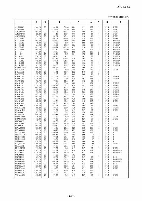
AP30A-59
17 703.08 MHz (27)
1 2 3 4 5 6 7 8 9
ALS00002 27 36.86 6.04 1.11 137 1 87.4 9/GR1ALS00003 27 37.50 5.60 0.75 132 1 87.4 9/GR2ARGINSU4 27 3.40 0.68 19 1 87.4 9/GR3ARGINSU5 27 3.77 0.70 13 1 87.4 9/GR4ARGSUR04 27 3.32 1.50 40 1 87.4 9/GR3ARGSUR05 27 2.54 2.38 152 1 87.4 9/GR4B CE311 27 3.04 2.06 174 1 87.4 8 9/GR7B CE312 27 3.44 2.09 174 1 87.4 8 9/GR9B CE411 27 3.86 1.38 49 1 87.4 8 9/GR7B CE412 27 3.57 1.56 52 1 87.4 8 9/GR9B CE511 .20 27 2.44 2.13 104 1 87.4 8 9/GR7B NO611 27 2.85 1.69 165 2 87.4 8 9/GR8B NO711 27 3.54 1.78 126 2 87.4 8 9/GR8B NO811 27 2.37 1.65 73 2 87.4 8 9/GR8B SU111 27 2 2.76 1.05 50 1 87.4 8 9/GR6B SU112 27 2.47 1.48 56 1 87.4 8 9/GR9B SU211 27 3.22 1.36 60 1 87.4 8 9/GR6B SU212 27 3.20 1.96 58 1 87.4 8 9/GR9BERBERMU 27 32.32 0.60 0.60 90 2 87.4BOLAND01 27 6.49 2.57 87 1 87.4 9/GR5BOL00001 27 2.52 2.19 85 1 87.4BRB00001 27 12.93 0.60 0.60 90 2 87.4CAN01101 27 57.24 3.45 1.27 157 1 87.4 9/GR10CAN01201 27 55..95 3.35 0.97 151 1 87.4 9/GR10CAN01202 27 55.63 2.74 1.12 32 1 87.4CAN01203 27 55.61 3.08 1.15 151 1 87.4 9/GR12CAN01303 27 57.12 3.54 0.91 154 1 87.4 9/GR12CAN01304 27 57.36 1.98 1.72 2 1 87.4 9/GR13CAN01403 27 52.02 4.68 0.78 148 1 87.4 9/GR12CAN01404 27 52.42 3.10 2.05 152 1 87.4 9/GR13CAN01405 27 52.39 2.84 2.29 172 1 87.4 9/GR14CAN01504 27 53.77 3.57 1.67 156 1 87.4 9/GR13CAN01505 27 53.79 3.30 1.89 162 1 87.4 9/GR14CAN01605 27 49.55 2.65 1.40 143 1 87.4 9/GR14CAN01606 27 49.55 2.40 1.65 148 1 87.4CHLCONT5 27 2.60 0.68 55 1 87.4 9/GR17CHLPAC02 27 1.36 0.68 69 1 87.4 9/GR17CLMAND01 27 6.49 2.57 87 1 87.4 9/GR5CLM00001 27 5.87 3.98 1.96 118 1 87.4CUB00001 27 21.62 2.24 0.68 168 1 87.4EQACAND1 27 6.49 2.57 87 1 87.4 9/GR5EQAGAND1 27 6.49 2.57 87 1 87.4 9/GR5GRD00059 27 12.29 0.60 0.60 90 1 87.4GRLDNK01 27 66.56 2.70 0.82 173 1 87.4 2GUY00201 27 4.78 1.44 0.85 95 1 87.4HWA00002 27 23.42 4.20 0.68 160 1 87.4 9/GR1HWA00003 27 23.42 4.25 0.68 159 1 87.4 9/GR2MEX01NTE 27 26.01 2.89 2.08 155 1 87.4 1MEX01SUR 27 19.82 3.05 2.09 4 1 87.4 1MEX02NTE 27 26.31 3.84 1.55 148 1 87.4 1MEX02SUR 27 19.88 3.18 1.87 157 1 87.4 1MSR00001 27 16.75 0.60 0.60 90 1 87.4 4PAQPAC01 27 0.60 0.60 90 1 87.4 9/GR17PRG00002 27 1.45 1.04 76 1 87.4PRUAND02 27 6.49 2.57 87 1 87.4 9/GR5PTRVIR01 27 36.32 8.24 3.56 171 1 87.4 1 6 9/GR20PTRVIR02 27 36.29 8.27 3.37 168 1 87.4 1 6 9/GR21URG00001 27 1.02 0.89 11 1 87.4USAEH001 27 36.17 6.42 3.49 12 1 87.4 1 5 6USAEH002 27 36.32 8.24 3.56 171 1 87.4 1 6 9/GR20USAEH003 27 36.29 8.27 3.37 168 1 87.4 1 6 9/GR21USAEH004 27 36.21 8.20 3.12 165 1 87.4 1 5 6USAPSA02 27 36.86 6.04 1.11 137 1 87.4 9/GR1USAPSA03 27 37.50 5.60 0.75 132 1 87.4 9/GR2USAWH101 27 40.68 4.36 2.15 162 1 87.4USAWH102 27 40.74 3.72 1.78 149 1 87.4VENAND03 27 6.49 2.57 87 1 87.4 9/GR5
- 677 -

AP30A-60
17 717.66 MHz (28)
1 2 3 4 5 6 7 8 9
ALS00002 28 36.82 6.03 1.12 137 2 87.4 9/GR1ALS00003 28 37.47 5.60 0.76 132 2 87.4 9/GR2ARGNORT4 28 3.86 1.99 48 2 87.4ARGNORT5 28 3.24 2.89 47 2 87.4B CE311 28 3.04 2.06 174 2 87.4 8 9/GR7B CE312 28 3.44 2.09 174 2 87.4 8 9/GR9B CE411 28 3.86 1.38 49 2 87.4 8 9/GR7B CE412 28 3.57 1.56 52 2 87.4 8 9/GR9B CE511 28 2.42 2.15 107 2 87.4 8 9/GR7B NO611 28 2.86 1.69 165 1 87.4 8 9/GR8B NO711 28 3.54 1.78 126 1 87.4 8 9/GR8B NO811 28 2.37 1.65 73 1 87.4 8 9/GR8B SE911 28 2.22 0.79 62 2 87.4 8B SU111 28 2.76 1.06 50 2 87.4 8 9/GR6B SU112 28 2.47 1.48 56 2 87.4 8 9/GR9B SU211 28 3.22 1.37 60 2 87.4 8 9/GR6B SU212 28 3.27 1.92 59 2 87.4 8 9/GR9CAN01101 28 57.24 3.45 1.27 157 2 87.4 9/GR10CAN01201 28 55.89 3.33 0.98 151 2 87.4 9/GR10CAN01202 28 55.62 2.75 1.11 32 2 87.4CAN01203 28 55.56 3.07 1.15 151 2 87.4 9/GR12CAN01303 28 57.12 3.54 0.92 154 2 87.4 9/GR12CAN01304 28 57.33 1.96 1.73 1 2 87.4 9/GR13CAN01403 28 52.02 4.67 0.79 148 2 87.4 9/GR12CAN01404 28 52.41 3.09 2.06 153 2 87.4 9/GR13CAN01405 28 52.34 2.82 2.30 172 2 87.4 9/GR14CAN01504 28 53.78 3.57 1.67 157 2 87.4 9/GR13CAN01505 28 53.76 3.30 1.89 162 2 87.4 9/GR14CAN01605 28 49.50 2.66 1.39 144 2 87.4 9/GR14CAN01606 28 49.51 2.41 1.65 148 2 87.4CHLCONT4 28 2.21 0.69 68 2 87.4 9/GR16CHLCONT6 28 3.65 1.31 39 2 87.4 9/GR16CRBBAH01 28 24.13 1.83 0.68 141 1 87.4 9/GR18CRBBER01 28 32.13 0.60 0.60 90 1 87.4 9/GR18CRBBLZ01 28 17.26 0.64 0.64 90 1 87.4 9/GR18CRBEC001 28 8.26 4.20 0.86 115 1 87.4 9/GR18CRBJMC01 28 17.97 0.99 0.68 151 1 87.4 9/GR18EQAC0001 28 1.48 1.15 65 1 87.4 9/GR19EQAG0001 28 0.94 0.89 99 1 87.4 9/GR19GRD00003 28 12.34 0.60 0.60 90 2 87.4GTMIFRB2 28 15.64 1.03 0.74 84 1 87.4GUFMGG02 28 8.47 4.16 0.81 123 2 87.4 2 7HWA00002 28 23.32 4.20 0.68 160 2 87.4 9/GR1HWA00003 28 23.42 4.25 0.68 159 2 87.4 9/GR2MEX01NTE 28 25.99 2.88 2.07 155 2 87.4 1MEX02NTE 80 28 26.32 3.80 1.57 149 2 87.4 1MEX02SUR 28 19.88 3.19 1.87 158 2 87.4 1PNRIFRB2 28 8.46 1.01 0.73 170 1 87.4PRU00004 28 3.74 2.45 112 2 87.4PTRVIR01 28 36.31 8.26 3.55 171 2 87.4 1 6 9/GR20PTRVIR02 28 36.38 8.10 3.45 168 2 87.4 1 6 9/GR21USAEH001 28 36.18 6.41 3.49 12 2 87.4 1 5 6USAEH002 28 36.31 8.26 3.55 171 2 87.4 1 6 9/GR20USAEH003 28 36.38 8.10 3.45 168 2 87.4 1 6 9/GR21USAEH004 28 36.21 8.20 3.12 165 2 87.4 1 5 6USAPSA02 28 36.82 6.03 1.12 137 2 87.4 9/GR1USAPSA03 28 37.47 5.60 0.76 132 2 87.4 9/GR2USAWH101 28 40.67 4.38 2.15 162 2 87.4USAWH102 28 40.71 3.74 1.79 149 2 87.4VEN02VEN 28 6.90 2.50 1.77 122 2 87.4 9/GR22VEN11VEN 28 6.90 2.50 1.77 122 2 87.4 9/GR22
- 678 -
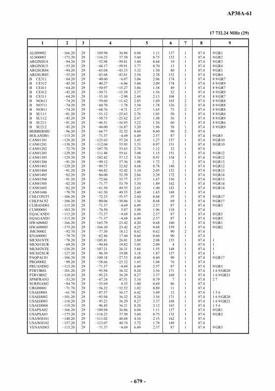
AP30A-61
17 732.24 MHz (29)
1 2 3 4 5 6 7 8 9
ALS00002 29 36.86 6.04 1.11 137 1 87.4 9/GR1ALS00003 29 37.50 5.60 0.75 132 1 87.4 9/GR2ARGINSU4 29 3.40 0.68 19 1 87.4 9/GR3ARGINSU5 29 3.77 0.70 13 1 87.4 9/GR4ARGSUR04 29 3.32 1.50 40 1 87.4 9/GR3ARGSUR05 29 2.54 2.38 152 1 87.4 9/GR4B CE311 29 3.04 2.06 174 1 87.4 8 9/GR7B CE312 29 3.44 2.09 174 1 87.4 8 9/GR9B CE411 29 3.86 1.38 49 1 87.4 8 9/GR7B CE412 29 3.57 1.56 52 1 87.4 8 9/GR9B CE511 29 2.44 2.13 104 1 87.4 8 9/GR7B NO611 29 2.85 1.69 165 2 87.4 8 9/GR8B NO711 29 3.54 1.78 126 2 87.4 8 9/GR8B NO811 29 2.37 1.65 73 2 87.4 8 9/GR8B SU111 29 2.76 1.05 50 1 87.4 8 9/GR6B SU112 29 2.47 1.48 56 1 87.4 8 9/GR9B SU211 29 3.22 1.36 60 1 87.4 8 9/GR6B SU212 29 3.20 1.96 58 1 87.4 8 9/GR9BERBERMU 29 32.32 0.60 0.60 90 2 87.4BOLAND01 29 6.49 2.57 87 1 87.4 9/GR5CAN01101 29 57.24 3.45 1.27 157 1 87.4 9/GR10CAN01201 29 55.95 3.35 0.97 151 1 87.4 9/GR10CAN01202 29 55.63 2.74 1.12 32 1 87.4CAN01203 29 55.61 3.08 1.15 151 1 87.4 9/GR12CAN01303 29 57.12 3.54 0.91 154 1 87.4 9/GR12CAN01304 29 57.36 1.98 1.72 2 1 87.4 9/GR13CAN01403 29 52.02 4.68 0.78 148 1 87.4 9/GR12CAN01404 29 52.42 3.10 2.05 152 1 87.4 9/GR13CAN01405 29 52.39 2.84 2.29 172 1 87.4 9/GR14CAN01504 29 53.77 3.57 1.67 156 1 87.4 9/GR13CAN01505 29 53.79 3.30 1.89 162 1 87.4 9/GR14CAN01605 29 49.55 2.65 1.40 143 1 87.4 9/GR14CAN01606 29 49.55 2.40 1.65 148 1 87.4CHLCONT5 29 2.60 0.68 55 1 87.4 9/GR17CHLPAC02 0 29 1.36 0.68 69 1 87.4 9/GR17CLMAND01 29 6.49 2.57 87 1 87.4 9/GR5CLM00001 29 5.87 3.98 1.96 118 1 87.4EQACAND1 29 6.49 2.57 87 1 87.4 9/GR5EQAGAND1 29 6.49 2.57 87 1 87.4 9/GR5HWA00002 29 23.42 4.20 0.68 160 1 87.4 9/GR1HWA00003 29 23.42 4.25 0.68 159 1 87.4 9/GR2JMC00002 29 18.12 0.62 0.62 90 2 87.4KNA00001 29 17.44 0.60 0.60 90 1 87.4MEX01NTE 29 26.01 2.89 2.08 155 1 87.4 1MEX01SUR 29 19.82 3.05 2.09 4 1 87.4 1MEX02NTE 29 26.31 3.84 1.55 148 1 87.4 1MEX02SUR 29 19.88 3.18 1.87 157 1 87.4 1PAQPAC01 29 0.60 0.60 90 1 87.4 9/GR17PRG00002 29 1.45 1.04 76 1 87.4PRUAND02 29 6.49 2.57 87 1 87.4 9/GR5PTRVIR01 29 36.32 8.24 3.56 171 1 87.4 1 6 9/GR20PTRVIR02 29 36.29 8.27 3.37 168 1 87.4 1 6 9/GR21SPMFRAN3 29 47.51 3.16 0.79 7 1 87.4 2 7SURINAM2 29 4.35 1.00 0.69 86 1 87.4URG00001 29 1.02 0.89 11 1 87.4USAEH001 29 36.17 6.42 3.49 12 1 87.4 1 5 6USAEH002 29 36.32 8.24 3.56 171 1 87.4 1 6 9/GR20USAEH003 29 36.29 8.27 3.37 168 1 87.4 1 6 9/GR21USAEH004 29 36.21 8.20 3.12 165 1 87.4 1 5 6USAPSA02 29 36.86 6.04 1.11 137 1 87.4 9/GR1USAPSA03 29 37.50 5.60 0.75 132 1 87.4 9/GR2USAWH101 29 40.68 4.36 2.15 162 1 87.4USAWH102 29 40.74 3.72 1.78 149 1 87.4VENAND03 29 6.49 2.57 87 1 87.4 9/GR5
- 679 -

AP30A-62
17 746.82 MHz (30)
1 2 3 4 5 6 7 8 9
ALS00002 30 36.82 6.03 1.12 137 2 87.4 9/GR1ALS00003 30 37.47 5.60 0.76 132 2 87.4 9/GR2ARGNORT4 30 3.86 1.99 48 2 87.4ARGNORT5 30 3.24 2.89 47 2 87.4ATNBEAM1 30 14.87 1.83 0.68 39 2 87.4B CE311 30 3.04 2.06 174 2 87.4 8 9/GR7B CE312 30 3.44 2.09 174 2 87.4 8 9/GR9B CE411 30 3.86 1.38 49 2 87.4 8 9/GR7B CE412 30 .30 3.57 1.56 52 2 87.4 8 9/GR9B CE511 30 2.42 2.15 107 2 87.4 8 9/GR7B NO611 30 2.86 1.69 165 1 87.4 8 9/GR8B NO711 30 3.54 1.78 126 1 87.4 8 9/GR8B NO811 30 2.37 1.65 73 1 87.4 8 9/GR8B SE911 30 2.22 0.79 62 2 87.4 8B SU111 30 2.76 1.06 50 2 87.4 8 9/GR6B SU112 30 2.47 1.48 56 2 87.4 8 9/GR9B SU211 30 3.22 1.37 60 2 87.4 8 9/GR6B SU212 30 3.27 1.92 59 2 87.4 8 9/GR9BLZ00001 30 17.27 0.62 0.62 90 2 87.4CAN01101 30 57.24 3.45 1.27 157 2 87.4 9/GR10CAN01201 30 55.89 3.33 0.98 151 2 87.4 9/GR10CAN01202 72.30 30 55.62 2.75 1.11 32 2 87.4CAN01203 30 55.56 3.07 1.15 151 2 87.4 9/GR12CAN01303 30 57.12 3.54 0.92 154 2 87.4 9/GR12CAN01304 30 57.33 1.96 1.73 1 2 87.4 9/GR13CAN01403 30 52.02 4.67 0.79 148 2 87.4 9/GR12CAN01404 30 52.41 3.09 2.06 153 2 87.4 9/GR13CAN01405 30 52.34 2.82 2.30 172 2 87.4 9/GR14CAN01504 30 53.78 3.57 1.67 157 2 87.4 9/GR13CAN01505 30 53.76 3.30 1.89 162 2 87.4 9/GR14CAN01605 30 49.50 2.66 1.39 144 2 87.4 9/GR14CAN01606 30 49.51 2.41 1.65 148 2 87.4CHLCONT4 30 2.21 0.69 68 2 87.4 9/GR16CHLCONT6 30 3.65 1.31 39 2 87.4 9/GR16CRBBAH01 30 24.13 1.83 0.68 141 1 87.4 9/GR18CRBBER01 30 32.13 0.60 0.60 90 1 87.4 9/GR18CRBBLZ01 30 17.26 0.64 0.64 90 1 87.4 9/GR18CRBEC001 30 8.26 4.20 0.86 115 1 87.4 9/GR18CRBJMC01 30 17.97 0.99 0.68 151 1 87.4 9/GR18CTR00201 30 9.67 0.82 0.68 119 2 87.4DMAIFRB1 30 15.35 0.60 0.60 90 2 87.4EQAC0001 30 1.48 1.15 65 1 87.4 9/GR19EQAG0001 30 0.94 0.89 99 1 87.4 9/GR19HWA00002 30 23.32 4.20 0.68 160 2 87.4 9/GR1HWA00003 30 23.42 4.25 0.68 159 2 87.4 9/GR2MEX01NTE 30 25.99 2.88 2.07 155 2 87.4 1MEX02NTE 30 26.32 3.80 1.57 149 2 87.4 1MEX02SUR 30 19.88 3.19 1.87 158 2 87.4 1NCG00003 30 12.90 1.05 1.01 176 1 87.4PRU00004 30 3.74 2.45 112 2 87.4PTRVIR01 30 36.31 8.26 3.55 171 2 87.4 1 6 9/GR20PTRVIR02 9.80 30 36.38 8.10 3.45 168 2 87.4 1 6 9/GR21USAEH001 30 36.18 6.41 3.49 12 2 87.4 1 5 6USAEH002 30 36.31 8.26 3.55 171 2 87.4 1 6 9/GR20USAEH003 30 36.38 8.10 3.45 168 2 87.4 1 6 9/GR21USAEH004 18.80 30 36.21 8.20 3.12 165 2 87.4 1 5 6USAPSA02 30 36.82 6.03 1.12 137 2 87.4 9/GR1USAPSA03 30 37.47 5.60 0.76 132 2 87.4 9/GR2USAWH101 30 40.67 4.38 2.15 162 2 87.4USAWH102 30 01 40.71 3.74 1.79 149 2 87.4VEN11VEN 30 6.90 2.50 1.77 122 2 87.4
- 680 -

AP30A-63
17 761.40 MHz (31)
1 2 3 4 5 6 7 8 9
ALS00002 31 36.86 6.04 1.11 137 1 87.4 9/GR1ALS00003 31 37.50 5.60 0.75 132 1 87.4 9/GR2ARGINSU4 31 3.40 0.68 19 1 87.4 9/GR3ARGINSU5 31 3.77 0.70 13 1 87.4 9/GR4ARGSUR04 31 3.32 1.50 40 1 87.4 9/GR3ARGSUR05 31 2.54 2.38 152 1 87.4 9/GR4B CE311 31 40.60 3.04 2.06 174 1 87.4 8 9/GR7B CE312 31 3.44 2.09 174 1 87.4 8 9/GR9B CE411 31 3.86 1.38 49 1 87.4 8 9/GR7B CE412 31 3.57 1.56 52 1 87.4 8 9/GR9B CE511 31 2.44 2.13 104 1 87.4 8 9/GR7B NO611 31 2.85 1.69 165 2 87.4 8 9/GR8B NO711 31 3.54 1.78 126 2 87.4 8 9/GR8B NO811 31 2.37 1.65 73 2 87.4 8 9/GR8B SU111 31 2.76 1.05 50 1 87.4 8 9/GR6B SU112 31 2.47 1.48 56 1 87.4 8 9/GR9B SU211 31 3.22 1.36 60 1 87.4 8 9/GR6B SU212 31 3.20 1.96 58 1 87.4 8 9/GR9BERBERMU 31 32.32 0.60 0.60 90 2 87.4BOLAND01 31 6.49 2.57 87 1 87.4 9/GR5BOL00001 31 2.52 2.19 85 1 87.4BRB00001 31 12.93 0.60 0.60 90 2 87.4CAN01101 31 57.24 3.45 1.27 157 1 87.4 9/GR10CAN01201 31 04 55.95 3.35 0.97 151 1 87.4 9/GR10CAN01202 31 55.63 2.74 1.12 32 1 87.4CAN01203 31 55.61 3.08 1.15 151 1 87.4 9/GR12CAN01303 31 57.12 3.54 0.91 154 1 87.4 9/GR12CAN01304 31 57.36 1.98 1.72 2 1 87.4 9/GR13CAN01403 31 52.02 4.68 0.78 148 1 87.4 9/GR12CAN01404 31 52.42 3.10 2.05 152 1 87.4 9/GR13CAN01405 31 52.39 2.84 2.29 172 1 87.4 9/GR14CAN01504 31 53.77 3.57 1.67 156 1 87.4 9/GR13CAN01505 31 53.79 3.30 1.89 162 1 87.4 9/GR14CAN01605 31 49.55 2.65 1.40 143 1 87.4 9/GR14CAN01606 31 49.55 2.40 1.65 148 1 87.4CHLCONT5 31 2.60 0.68 55 1 87.4 9/GR17CHLPAC02 31 1.36 0.68 69 1 87.4 9/GR17CLMAND01 31 6.49 2.57 87 1 87.4 9/GR5CLM00001 31 5.87 3.98 1.96 118 1 87.4CUB00001 31 21.62 2.24 0.68 168 1 87.4EQACAND1 31 69 6.49 2.57 87 1 87.4 9/GR5EQAGAND1 31 6.49 2.57 87 1 87.4 9/GR5GRD00059 31 12.29 0.60 0.60 90 1 87.4GRLDNK01 31 66.56 2.70 0.82 173 1 87.4 2GUY00201 31 4.78 1.44 0.85 95 1 87.4HWA00002 31 23.42 4.20 0.68 160 1 87.4 9/GR1HWA00003 31 23.42 4.25 0.68 159 1 87.4 9/GR2MEX01NTE 31 26.01 2.89 2.08 155 1 87.4 1MEX01SUR 31 19.82 3.05 2.09 4 1 87.4 1MEX02NTE 31 .21 26.31 3.84 1.55 148 1 87.4 1MEX02SUR 31 19.88 3.18 1.87 157 1 87.4 1MSR00001 31 16.75 0.60 0.60 90 1 87.4 4PAQPAC01 31 0.60 0.60 90 1 87.4 9/GR17PRG00002 31 1.45 1.04 76 1 87.4PRUAND02 31 6.49 2.57 87 1 87.4 9/GR5PTRVIR01 31 36.32 8.24 3.56 171 1 87.4 1 6 9/GR20PTRVIR02 31 36.29 8.27 3.37 168 1 87.4 1 6 9/GR21URG00001 31 1.02 0.89 11 1 87.4USAEH001 31 36.17 6.42 3.49 12 1 87.4 1 5 6USAEH002 31 36.32 8.24 3.56 171 1 87.4 1 6 9/GR20USAEH003 31 36.29 8.27 3.37 168 1 87.4 1 6 9/GR21USAEH004 31 36.21 8.20 3.12 165 1 87.4 1 5 6USAPSA02 31 36.86 6.04 1.11 137 1 87.4 9/GR1USAPSA03 31 37.50 5.60 0.75 132 1 87.4 9/GR2USAWH101 31 40.68 4.36 2.15 162 1 87.4USAWH102 31 40.74 3.72 1.78 149 1 87.4VENAND03 31 .37 6.49 2.57 87 1 87.4 9/GR5
- 681 -
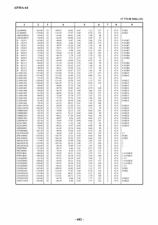
AP30A-64
17 775.98 MHz (32)
1 2 3 4 5 6 7 8 9
ALS00002 32 36.82 6.03 1.12 137 2 87.4 9/GR1ALS00003 32 37.47 5.60 0.76 132 2 87.4 9/GR2ARGNORT4 32 3.86 1.99 48 2 87.4ARGNORT5 32 3.24 2.89 47 2 87.4B CE311 32 3.04 2.06 174 2 87.4 8 9/GR7B CE312 32 3.44 2.09 174 2 87.4 8 9/GR9B CE411 32 3.86 1.38 49 2 87.4 8 9/GR7B CE412 32 3.57 1.56 52 2 87.4 8 9/GR9B CE511 32 2.42 2.15 107 2 87.4 8 9/GR7B NO611 32 2.86 1.69 165 1 87.4 8 9/GR8B NO711 32 3.54 1.78 126 1 87.4 8 9/GR8B NO811 32 71 2.37 1.65 73 1 87.4 8 9/GR8B SE911 32 2.22 0.79 62 2 87.4 8B SU111 32 2.76 1.06 50 2 87.4 8 9/GR6B SU112 32 2.47 1.48 56 2 87.4 8 9/GR9B SU211 32 3.22 1.37 60 2 87.4 8 9/GR6B SU212 32 3.27 1.92 59 2 87.4 8 9/GR9CAN01101 32 57.24 3.45 1.27 157 2 87.4 9/GR10CAN01201 32 55.89 3.33 0.98 151 2 87.4 9/GR10CAN01202 32 55.62 2.75 1.11 32 2 87.4CAN01203 32 55.56 3.07 1.15 151 2 87.4 9/GR12CAN01303 32 57.12 3.54 0.92 154 2 87.4 9/GR12CAN01304 32 57.33 1.96 1.73 1 2 87.4 9/GR13CAN01403 32 52.02 4.67 0.79 148 2 87.4 9/GR12CAN01404 32 52.41 3.09 2.06 153 2 87.4 9/GR13CAN01405 32 52.34 2.82 2.30 172 2 87.4 9/GR14CAN01504 32 53.78 3.57 1.67 157 2 87.4 9/GR13CAN01505 32 53.76 3.30 1.89 162 2 87.4 9/GR14CAN01605 32 61.54 49.50 2.66 1.39 144 2 87.4 9/GR14CAN01606 32 49.51 2.41 1.65 148 2 87.4CHLCONT4 32 2.21 0.69 68 2 87.4 9/GR16CHLCONT6 32 3.65 1.31 39 2 87.4 9/GR16CRBBAH01 32 24.13 1.83 0.68 141 1 87.4 9/GR18CRBBER01 32 32.13 0.60 0.60 90 1 87.4 9/GR18CRBBLZ01 32 17.26 0.64 0.64 90 1 87.4 9/GR18CRBEC001 32 8.26 4.20 0.86 115 1 87.4 9/GR18CRBJMC01 32 17.97 0.99 0.68 151 1 87.4 9/GR18EQAC0001 32 1.48 1.15 65 1 87.4 9/GR19EQAG0001 32 0.94 0.89 99 1 87.4 9/GR19GRD00003 32 12.34 0.60 0.60 90 2 87.4GTMIFRB2 32 15.64 1.03 0.74 84 1 87.4GUFMGG02 32 8.47 4.16 0.81 123 2 87.4 2 7HWA00002 32 23.32 4.20 0.68 160 2 87.4 9/GR1HWA00003 32 23.42 4.25 0.68 159 2 87.4 9/GR2MEX01NTE 32 25.99 2.88 2.07 155 2 87.4 1MEX02NTE 32 26.32 3.80 1.57 149 2 87.4 1MEX02SUR 32 19.88 3.19 1.87 158 2 87.4 1PNRIFRB2 32 8.46 1.01 0.73 170 1 87.4PRU00004 32 3.74 2.45 112 2 87.4PTRVIR01 32 36.31 8.26 3.55 171 2 87.4 1 6 9/GR20PTRVIR02 32 36.38 8.10 3.45 168 2 87.4 1 6 9/GR21USAEH001 32 36.18 6.41 3.49 12 2 87.4 1 5 6USAEH002 32 36.31 8.26 3.55 171 2 87.4 1 6 9/GR20USAEH003 32 36.38 8.10 3.45 168 2 87.4 1 6 9/GR21USAEH004 32 36.21 8.20 3.12 165 2 87.4 1 5 6USAPSA02 32 36.82 6.03 1.12 137 2 87.4 9/GR1USAPSA03 32 37.47 5.60 0.76 132 2 87.4 9/GR2USAWH101 32 40.67 4.38 2.15 162 2 87.4USAWH102 .80 32 40.71 3.74 1.79 149 2 87.4VEN02VEN 32 6.90 2.50 1.77 122 2 87.4 9/GR22VEN11VEN 32 6.90 2.50 1.77 122 2 87.4 9/GR22
- 682 -
AP30A-65
ARTICLE 9A (REV.WRC-15)
Plan for feeder links for the broadcasting-satellite service in the fixed-satellite service in the frequency bands
14.5-14.8 GHz and 17.3-18.1 GHz in Regions 1 and 3
9A.1 COLUMN HEADINGS OF THE PLAN
Col. 1 Notifying administration symbol.
Col. 2 Beam identification (Column 2, normally, contains the symbol designating the administration or the geographical area taken from Table B1 of the Preface to the International Frequency List, followed by the symbol designating the service area).
Col. 3 Nominal orbital position, in degrees and hundredths of a degree from the Greenwich meridian (negative values indicate longitudes which are west of the Greenwich meridian; positive values indicate longitudes which are east of the Greenwich meridian).
Col. 4 Nominal intersection of the beam axis with the Earth (boresight or aim point in the case of a non-elliptical beam), longitude and latitude, in degrees and hundredths of a degree.
Col. 5 Space station receiving antenna characteristics (elliptical beams). This Column contains three numerical values corresponding to the major axis, the minor axis and the major axis orientation respectively of the elliptical cross-section half-power beam, in degrees and hundredths of a degree. Orientation of the ellipse determined as follows: in a plane normal to the beam axis, the direction of a major axis of the ellipse is specified as the angle measured anticlockwise from a line parallel to the equatorial plane to the major axis of the ellipse, to the nearest degree.
Col. 6 Space station receiving antenna pattern code.
The codes used for the antenna pattern of the receiving space station (feeder link) antenna are defined as follows:
R13RSS Figure B (Curves A, B and C) and § 3.7.3 in Annex 3
R123FR Figure C and § 3.7.3 in Annex 3
MODRSS Figure B (Curves A , B and C) and § 3.7.3 in Annex 3(Recommendation ITU-R BO.1296)
necessary antenna pattern data are provided by shaped beam data submitted by the administration. These data are stored in Column 7. A particular shaped beam is identified by the combination of Column 1, Column 7 and Column 14. In such cases the maximum cross-polar gain is given in Column 8, Cross-polar gain field.
- 683 -

AP30A-66
ode
of two or more elliptical beams. Each composite beam is described in the special composite beam file having the same name plus a GXT extension (e.g. the description of the CB_COMP_BM1 composite beam is stored in the CB_COMP_BM1.GXT file).
Col. 7 Space station receiving antenna shaped (non-elliptical, non-composite) beam identification.
Col. 8 Maximum space station receiving antenna co-polar and cross-polar (in the case of shaped beam) isotropic gain (dBi).
Col. 9 Earth station transmitting antenna pattern code and maximum gain (dBi).
The codes used for transmitting earth station (feeder-link) antenna patterns are defined as follows:
R13TES Figure A (Curves A and B) and § 3.5.3 in Annex 3
MODTES Figure A (Curves A and B ) and § 3.5.3 in Annex 3(Recommendation ITU-R BO.1295)
Col. 10 Polarization (CL circular left, CR circular right, LE linear referenced to the equatorial plane) and polarization angle in degrees and hundredths of a degree (in the case of linear polarization only).
Col. 11 e.i.r.p. in the direction of maximum radiation (dBW).
Col. 12 Permitted increase in earth station e.i.r.p. (dB) for the purpose of power control (see § 3.11 of Annex 3).32 (WRC-15)
Col. 13 Designation of emission.
Col. 14 Identity of the space station.
Col. 15 Group code (an identification code which indicates that all assignments with the same group identification code will be treated as a group).
Group code: if an assignment is part of the group:
a) the equivalent protection margin to be used for the application of Article 4 shall be calculated on the following basis:
for the calculation of interference to assignments that are part of a group, only the interference contributions from assignments that are not part of the same group are to be included, and
_______________32 (SUP - WRC-15)
- 684 -
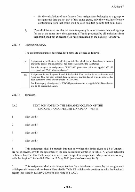
AP30A-67
for the calculation of interference from assignments belonging to a group to assignments that are not part of that same group, only the worst interference contribution from that group shall be used on a test point to test point basis.
b) If an administration notifies the same frequency in more than one beam of a group for use at the same time, the aggregate C/I ratio produced by all emissions from that group shall not exceed the C/I ratio calculated on the basis of § a) above.
Col. 16 Assignment status.
The assignment status codes used for beams are defined as follows:
P Assignment in the Regions 1 and 3 feeder-link Plan which has not been brought into use and/or the date of bringing into use has not been confirmed to the Bureau.For this category of assignments, WRC-2000 protection ratios are applied (27 dB co-channel and 22 dB adjacent channel).
PE Assignment in the Regions 1 and 3 feeder-link Plan, which is in conformity with Appendix 30A, has been notified, brought into use and the date of bringing into use has been confirmed to the Bureau before 12 May 2000. For this category of assignments, WRC-97 protection ratios are applied (30 dB co-channel and 22 dB adjacent channel).
Col. 17 Remarks.
9A.2 TEXT FOR NOTES IN THE REMARKS COLUMN OF THEREGIONS 1 AND 3 FEEDER-LINK PLAN (WRC-15)
1 (Not used.)
2 (Not used.)
3 (Not used.)
4 (Not used.)
5 This assignment shall be brought into use only when the limits given in § 5 of Annex 1are not exceeded, or with the agreement of the administrations identified in Table 1A, whose networks or beams listed in this Table may be affected with respect to assignments which are in conformity with the Region 2 feeder-link Plan on 12 May 2000 (see also Note to § 9A.2).
6 This assignment shall not claim protection from interference caused by the assignments which pertain to networks or beams identified in Table 1B which are in conformity with the Region 2 feeder-link Plan on 12 May 2000 (see also Note to § 9A.2).
- 685 -
AP30A-68
7 This assignment shall not claim protection from interference caused by the assignments which pertain to networks or beams identified in Table 1B which are recorded in the Master Register with a favourable finding prior to 12 May 2000 (see also Note to § 9A.2).
The methodology and criteria for this analysis shall be those contained in § 1 of Annex 4, modified to take into consideration the system noise temperature of the received space station to be 600 K and to apply a T/T criterion of 6%.
8 Provisional beam. These assignments have been included in the Regions 1 and 3 feeder-link Plan by WRC-97. These assignments are for exclusive use by Palestine, subject to the Israeli-Palestinian Interim Agreement of 28 September 1995, Resolution 741 of the Council notwithstanding and Resolution 99 (Minneapolis, 1998) of the Plenipotentiary Conference.
9 (Not used.)
10 (SUP - WRC-12)
NOTE In cases where assignments from the WRC-97 Plans without Remarks were included in the WRC-2000 Regions 1and 3 feeder-link Plan without change, or with conversion of modulation from analogue to digital, or a change from normal roll-off to fast roll-off antenna characteristics, the coordination status afforded by the WRC-97 Plans shall be preserved.
In cases where assignments from the WRC-97 Plans with Remarks were included in the WRC-2000 Regions 1 and 3feeder-link Plan without change, or with conversion of modulation from analogue to digital, or a change from normal roll-off to fast roll-off antenna pattern, the compatibility will be reassessed using the revised criteria and methodology of WRC-2000 and the Remarks of the WRC-97 Plans assignment will either be maintained or reduced on the basis of the results of this analysis.
In other cases, the methodology described in Notes 5 to 7 shall be applied.
- 686 -
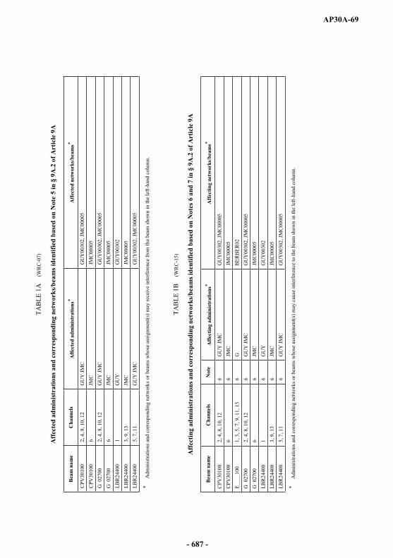
AP30A-69
TAB
LE 1
A(W
RC
-07)
Aff
ecte
d ad
min
istra
tions
and
cor
resp
ondi
ng n
etw
orks
/bea
ms i
dent
ified
bas
ed o
n N
ote
5 in
§ 9
A.2
of A
rtic
le 9
A
Bea
m n
ame
Cha
nnel
sA
ffec
ted
adm
inis
trat
ions
*A
ffec
ted
netw
orks
/bea
ms*
CPV
3010
02,
4, 8
, 10,
12
GU
Y JM
CG
UY
0030
2, JM
C00
005
CPV
3010
06
JMC
JMC
0000
5G
027
002,
4, 8
, 10,
12
GU
Y JM
CG
UY
0030
2, JM
C00
005
G 0
2700
6JM
CJM
C000
05LB
R24
400
1G
UY
GU
Y00
302
LBR
2440
03,
9, 1
3JM
CJM
C000
05LB
R24
400
5, 7
, 11
GU
Y JM
CG
UY
0030
2, JM
C00
005
*A
dmin
istra
tions
and
cor
resp
ondi
ng n
etw
orks
or b
eam
s who
se a
ssig
nmen
t(s) m
ay re
ceiv
e in
terfe
renc
e fro
m th
e be
am sh
own
in th
e le
ft-ha
nd c
olum
n.
TAB
LE 1
B
(W
RC
-15)
Aff
ectin
g ad
min
istr
atio
ns a
nd c
orre
spon
ding
net
wor
ks/b
eam
s ide
ntifi
ed b
ased
on
Not
es 6
and
7 in
§ 9
A.2
of A
rtic
le 9
A
Bea
m n
ame
Cha
nnel
sN
ote
Aff
ectin
g ad
min
istr
atio
ns*
Aff
ectin
g ne
twor
ks/b
eam
s*
CPV
3010
02,
4, 8
, 10,
12
6G
UY
JMC
GU
Y00
302,
JMC
0000
5C
PV30
100
66
JMC
JMC
0000
5E_
___1
001,
3, 5
, 7, 9
, 11,
13
6G
BER
BER
02G
027
002,
4, 8
, 10,
12
6G
UY
JMC
GU
Y00
302,
JMC
0000
5G
027
006
6JM
CJM
C00
005
LBR
2440
01
6G
UY
GU
Y00
302
LBR
2440
03,
9, 1
36
JMC
JMC
0000
5LB
R24
400
5, 7
, 11
6G
UY
JMC
GU
Y00
302,
JMC
0000
5
*A
dmin
istra
tions
and
corre
spon
ding
netw
orks
or b
eam
s who
se a
ssig
nmen
t(s) m
ay c
ause
inte
rfer
ence
to th
e be
am sh
own
in th
e le
ft-h
and
colu
mn.
- 687 -

AP30A-70
TABLE 2A
Table showing correspondence between channel numbers and assigned frequencies1
for the feeder links in the frequency band 14.5-14.8 GHz
Channel No. Assigned feeder-link frequency (MHz)
1 14 525.302 14 544.483 14 563.664 14 582.845 14 602.026 14 621.207 14 640.388 14 659.569 14 678.74
10 14 697.9211 14 717.1012 14 736.2813 14 755.4614 14 774.64
1 Assigned frequency = 14 506.12 + 19.18 n, where n is the channel number.
TABLE 2B
Table showing correspondence between channel numbers and assigned frequencies1
for the feeder links in the frequency band 17.3-18.1 GHz
Channel No.Assigned feeder-link
frequency (MHz)
Channel No.Assigned feeder-link
frequency(MHz)
1 17 327.48 21 17 711.082 17 346.66 22 17 730.263 17 365.84 23 17 749.444 17 385.02 24 17 768.625 17 404.20 25 17 787.806 17 423.38 26 17 806.987 17 442.56 27 17 826.168 17 461.74 28 17 845.349 17 480.92 29 17 864.52
10 17 500.10 30 17 883.7011 17 519.28 31 17 902.8812 17 538.46 32 17 922.0613 17 557.64 33 17 941.2414 17 576.82 34 17 960.4215 17 596.00 35 17 979.6016 17 615.18 36 17 998.7817 17 634.36 37 18 017.9618 17 653.54 38 18 037.1419 17 672.72 39 18 056.3220 17 691.90 40 18 075.50
1 Assigned frequency = 17 308.3 + 19.18 n, where n is the channel number.
- 688 -

AP30A-71
TAB
LE 3
A1
Bas
ic c
hara
cter
istic
s of t
he R
egio
ns 1
and
3 fe
eder
-link
Pla
n in
the
freq
uenc
y ba
nd 1
4.5-
14.8
GH
z (s
orte
d by
adm
inis
trat
ion)
12
34
56
78
910
1112
1314
1516
17
Adm
in.
sym
bol
Bea
m
iden
tific
atio
nO
rbita
l po
sitio
n
Bor
esig
htSp
ace
stat
ion
ante
nna
char
acte
rist
ics
Spac
e st
atio
n an
tenn
a co
deSh
aped
be
am
Spac
e st
atio
n an
tenn
aga
in
Ear
th
stat
ion
ante
nna
Pola
riza
tion
e.i.r
.p.
Pow
er
cont
rol
Des
igna
tion
of e
mis
sion
Iden
tity
of
the
spac
e st
atio
n
Gro
up
code
Stat
usR
emar
ks
Lon
g.L
at.
Maj
orax
isM
inor
axis
Ori
en-
tatio
nC
o-po
lar
Cro
ss-
pola
rC
ode
Gai
nT
ype
Ang
le
AFS
AFS0
2101
4.80
24.50
28.00
3.13
1.68
27.00
MODR
SS
37
.24MO
DTES
57
.00CL
82.0
27M0
G7W
4LP
AFS
AFS0
2102
4.80
24.50
28.00
3.13
1.68
27.00
MODR
SS
37
.24MO
DTES
57
.00CR
82.0
27M0
G7W
4LP
CHN
CHN1
9001
122.0
011
4.17
23.32
0.91
0.60
2.88
MODR
SS
47
.08MO
DTES
57
.00CL
84.0
27M0
G7W
4CP
CHN
CHN1
9002
122.0
011
4.17
23.32
0.91
0.60
2.88
MODR
SS
47
.08MO
DTES
57
.00CR
84.0
27M0
G7W
4CP
CME
CME3
0001
13.00
12.70
6.20
2.54
1.68
87.00
MODR
SS
38
.15MO
DTES
57
.00CL
84.0
27M0
G7W
4IP
CME
CME3
0002
13.00
12.70
6.20
2.54
1.68
87.00
MODR
SS
38
.15MO
DTES
57
.00CR
84.0
27M0
G7W
4IP
ETH
ETH0
9201
36.00
40.49
9.20
2.83
2.26
174.4
4MO
DRSS
36.40
MODT
ES
57.00
CL82
.027
M0G7
W
4P
P
ETH
ETH0
9202
36.00
40.49
9.20
2.83
2.26
174.4
4MO
DRSS
36.40
MODT
ES
57.00
CR82
.027
M0G7
W
4P
P
GHA
GHA1
0801
25.00
1.20
7.90
1.48
1.06
102.0
0MO
DRSS
42.49
MODT
ES
57.00
CR83
.027
M0G7
W
4F
P
GHA
GHA1
0802
25.00
1.20
7.90
1.48
1.06
102.0
0MO
DRSS
42.49
MODT
ES
57.00
CL83
.027
M0G7
W
4F
P
IND
INDA
_101
55.80
76.16
14.72
CB_R
SS_IN
DA
45.66
MODT
ES
57.00
CR82
.027
M0G7
W
4U
P
IND
INDA
_102
55.80
76.16
14.72
CB_R
SS_IN
DA
45.66
MODT
ES
57.00
CL82
.027
M0G7
W
4U
P
IRN
IRN1
0901
34.00
54.20
32.40
3.82
1.82
149.0
0MO
DRSS
36.03
MODT
ES
57.00
CR82
.027
M0G7
W
4S
P
IRN
IRN1
0902
34.00
54.20
32.40
3.82
1.82
149.0
0MO
DRSS
36.03
MODT
ES
57.00
CL82
.027
M0G7
W
4S
P
IRQ
IRQ2
5601
50.00
43.86
32.86
1.82
1.34
162.6
5MO
DRSS
40.58
MODT
ES
57.00
CL82
.027
M0G7
W
4M
P
IRQ
IRQ2
5602
50.00
43.86
32.86
1.82
1.34
162.6
5MO
DRSS
40.58
MODT
ES
57.00
CR82
.027
M0G7
W
4M
P
KOR
KO11
201D
116.0
012
7.50
36.00
1.24
1.02
168.0
0R1
3RSS
43.40
R13T
ES
57.30
CL82
.027
M0G7
W
KORE
ASAT
-1
03
PE
KOR
KOR1
1201
116.0
012
7.50
36.00
1.24
1.02
168.0
0R1
3RSS
43.40
R13T
ES
57.30
CL82
.027
M0F8
W
KORE
ASAT
-1
03
PE
MOZ
MOZ3
0701
1.00
34.00
18.00
3.57
1.38
55.00
MODR
SS
37
.52MO
DTES
57
.00CL
82.0
27M0
G7W
4KP
MOZ
MOZ3
0702
1.00
34.00
18.00
3.57
1.38
55.00
MODR
SS
37
.52MO
DTES
57
.00CR
82.0
27M0
G7W
4KP
NIG
NIG1
1901
19.20
7.80
9.40
2.16
2.02
45.00
MODR
SS
38
.05MO
DTES
57
.00CR
82.0
27M0
G7W
4GP
NIG
NIG1
1902
19.20
7.80
9.40
2.16
2.02
45.00
MODR
SS
38
.05MO
DTES
57
.00CL
82.0
27M0
G7W
4GP
NMB
NMB0
2501
18.80
17.50
21.60
2.66
1.90
48.00
MODR
SS
37
.41MO
DTES
57
.00CL
82.0
27M0
G7W
4HP
NMB
NMB0
2502
18.80
17.50
21.60
2.66
1.90
48.00
MODR
SS
37
.41MO
DTES
57
.00CR
82.0
27M0
G7W
4HP
NPL
NPL1
2201
50.00
83.70
28.30
1.72
0.60
163.0
0MO
DRSS
44.31
MODT
ES
57.00
CR82
.027
M0G7
W
4N
P
- 689 -
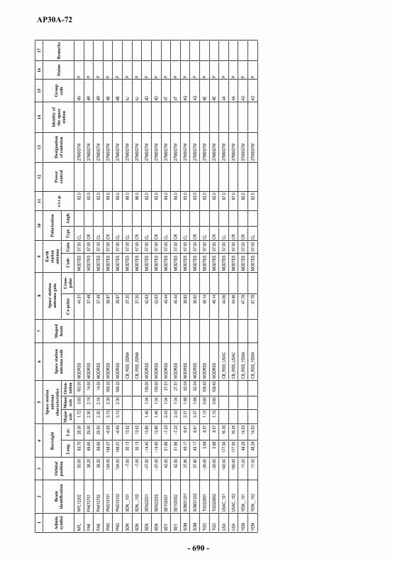
AP30A-72
12
34
56
78
910
1112
1314
1516
17
Adm
in.
sym
bol
Bea
m
iden
tific
atio
nO
rbita
l po
sitio
n
Bor
esig
htSp
ace
stat
ion
ante
nna
char
acte
rist
ics
Spac
e st
atio
n an
tenn
a co
deSh
aped
be
am
Spac
e st
atio
n an
tenn
aga
in
Ear
th
stat
ion
ante
nna
Pola
riza
tion
e.i.r
.p.
Pow
er
cont
rol
Des
igna
tion
of e
mis
sion
Iden
tity
of
the
spac
e st
atio
n
Gro
up
code
Stat
usR
emar
ks
Lon
g.L
at.
Maj
orax
isM
inor
axis
Ori
en-
tatio
nC
o-po
lar
Cro
ss-
pola
rC
ode
Gai
nT
ype
Ang
le
NPL
NPL1
2202
50.00
83.70
28.30
1.72
0.60
163.0
0MO
DRSS
44.31
MODT
ES
57.00
CL82
.027
M0G7
W
4N
P
PAK
PAK1
2701
38.20
69.60
29.50
2.30
2.16
14.00
MODR
SS
37
.49MO
DTES
57
.00CR
82.0
27M0
G7W
4RP
PAK
PAK1
2702
38.20
69.60
29.50
2.30
2.16
14.00
MODR
SS
37
.49MO
DTES
57
.00CL
82.0
27M0
G7W
4RP
PNG
PNG1
3101
134.0
014
8.07
6.65
3.13
2.30
168.3
2MO
DRSS
38.87
MODT
ES
57.00
CR89
.027
M0G7
W
4B
P
PNG
PNG1
3102
134.0
014
8.07
6.65
3.13
2.30
168.3
2MO
DRSS
38.87
MODT
ES
57.00
CL89
.027
M0G7
W
4B
P
SDN
SDN_
_101
7.00
30.13
13.52
CB_R
SS_S
DNA
37.20
MODT
ES
57.00
CL86
.027
M0G7
W
4J
P
SDN
SDN_
_102
7.00
30.13
13.52
CB_R
SS_S
DNA
37.20
MODT
ES
57.00
CR86
.027
M0G7
W
4J
P
SEN
SEN2
2201
37.00
14.40
13.80
1.46
1.04
139.0
0MO
DRSS
42.63
MODT
ES
57.00
CL82
.027
M0G7
W
4D
P
SEN
SEN2
2202
37.00
14.40
13.80
1.46
1.04
139.0
0MO
DRSS
42.63
MODT
ES
57.00
CR82
.027
M0G7
W
4D
P
SEY
SEY0
0001
42.50
51.86
7.23
2.43
1.04
27.51
MODR
SS
40
.44MO
DTES
57
.00CL
84.0
27M0
G7W
4TP
SEY
SEY0
0002
42.50
51.86
7.23
2.43
1.04
27.51
MODR
SS
40
.44MO
DTES
57
.00CR
84.0
27M0
G7W
4TP
SOM
SOM3
1201
37.80
45.17
6.61
3.37
1.68
62.04
MODR
SS
36
.92MO
DTES
57
.00CL
83.0
27M0
G7W
4QP
SOM
SOM3
1202
37.80
45.17
6.61
3.37
1.68
62.04
MODR
SS
36
.92MO
DTES
57
.00CR
83.0
27M0
G7W
4QP
TGO
TGO2
2601
30.00
0.68
8.57
1.13
0.60
108.4
3MO
DRSS
46.14
MODT
ES
57.00
CL82
.027
M0G7
W
4E
P
TGO
TGO2
2602
30.00
0.68
8.57
1.13
0.60
108.4
3MO
DRSS
46.14
MODT
ES
57.00
CR82
.027
M0G7
W
4E
P
USA
USAC
_101
140.0
017
7.50
16.35
CB_R
SS_U
SAC
44.06
MODT
ES
57.00
CL87
.027
M0G7
W
4A
P
USA
USAC
_102
140.0
017
7.50
16.35
CB_R
SS_U
SAC
44.06
MODT
ES
57.00
CR87
.027
M0G7
W
4A
P
YEM
YEM_
_101
11.00
48.29
14.53
CB_R
SS_Y
EMA
47.78
MODT
ES
57.00
CR82
.027
M0G7
W
4O
P
YEM
YEM_
_102
11.00
48.29
14.53
CB_R
SS_Y
EMA
47.78
MODT
ES
57.00
CL82
.027
M0G7
W
4O
P
- 690 -

AP30A-73
TAB
LE 3
A2
(WR
C-1
5)
Bas
ic c
hara
cter
istic
s of t
he R
egio
ns 1
and
3 fe
eder
-link
Pla
n in
the
freq
uenc
y ba
nd 1
7.3-
18.1
GH
z (s
orte
d by
adm
inis
trat
ion)
12
34
56
78
910
1112
1314
1516
17
Adm
in.
sym
bol
Bea
m
iden
tific
atio
nO
rbita
l po
sitio
n
Bor
esig
htSp
ace
stat
ion
ante
nna
char
acte
rist
ics
Spac
e st
atio
n an
tenn
a co
deSh
aped
be
am
Spac
e st
atio
n an
tenn
aga
inE
arth
stat
ion
ante
nna
Pola
riza
tion
e.i.r
.p.
Pow
er
cont
rol
Des
igna
tion
of
emis
sion
Iden
tity
of
the
spac
e st
atio
n
Gro
up
code
Stat
usR
emar
ks
Lon
g.L
at.
Maj
or
axis
Min
or
axis
Ori
en-
tatio
nC
o-po
lar
Cro
ss-
pola
rC
ode
Gai
nT
ype
Ang
le
AFG
AFG2
4501
50.00
67.00
34.30
1.89
1.19
18.00
MODR
SS
40.93
MODT
ES
57.00
CL84
.027
M0G7
W
7IP
AFG
AFG2
4502
50.00
67.00
34.30
1.89
1.19
18.00
MODR
SS
40.93
MODT
ES
57.00
CR84
.027
M0G7
W
7IP
AGL
AGL2
9500
16.43
2.66
1.75
77.43
MODR
SS
37.77
MODT
ES
57.00
CR84
.027
M0G7
W
PAL
BAL
B296
0062
.0019
.5041
.370.6
00.6
069
.35MO
DRSS
48
.88MO
DTES
57
.00CL
82.6
27M0
G7W
P
ALG
ALG2
5152
1.50
27.60
3.65
2.94
135.0
0MO
DRSS
34
.14MO
DTES
57
.00CL
84.0
27M0
G7W
P
AND
AND3
4100
1.60
42.50
0.60
0.60
0.00
MODR
SS
48.88
MODT
ES
57.00
CL83
.027
M0G7
W
PAR
MAR
M064
0022
.8044
.9939
.950.7
30.6
014
8.17
MODR
SS
48.02
MODT
ES
57.00
CR84
.027
M0G7
W
PAR
SAR
S003
7517
.0044
.6023
.404.2
12.4
814
5.00
MODR
SS
34.26
MODT
ES
57.00
CL84
.027
M0G7
W
54P
ARS
ARS3
4000
17.00
44.60
23.40
4.21
2.48
145.0
0MO
DRSS
34
.28MO
DTES
57
.00CL
84.0
27M0
G7W
54
PAU
SAU
S004
0015
2.00
135.0
07.1
95.2
014
0.00
MODR
SS
28.71
MODT
ES
57.00
CL87
.027
M0G7
W
30P
AUS
AUS0
0401
152.0
096
.830.6
00.6
00.0
0MO
DRSS
48
.88MO
DTES
57
.00CL
87.0
27M0
G7W
30
PAU
SAU
S004
0215
2.00
105.6
90.6
00.6
00.0
0MO
DRSS
48
.88MO
DTES
57
.00CL
87.0
27M0
G7W
30
PAU
SAU
S004
0315
2.00
110.5
20.6
00.6
00.0
0MO
DRSS
48
.88MO
DTES
57
.00CL
87.0
27M0
G7W
30
PAU
SAU
S004
0415
2.00
158.9
40.6
00.6
00.0
0MO
DRSS
48
.88MO
DTES
57
.00CL
87.0
27M0
G7W
30
PAU
SAU
S004
0515
2.00
159.0
60.6
00.6
00.0
0MO
DRSS
48
.88MO
DTES
57
.00CL
87.0
27M0
G7W
30
PAU
SAU
S004
0615
2.00
167.9
30.6
00.6
00.0
0MO
DRSS
48
.88MO
DTES
57
.00CL
87.0
27M0
G7W
30
PAU
SAU
S004
0A15
2.00
135.3
66.8
94.8
314
1.15
R123
FR
29.23
MODT
ES
57.00
CL87
.027
M0G7
W
30P
AUS
AUS0
0500
152.0
013
5.00
7.19
5.20
140.0
0MO
DRSS
28
.71MO
DTES
57
.00CR
87.0
27M0
G7W
41
PAU
SAU
S005
0115
2.00
96.83
0.60
0.60
0.00
MODR
SS
48.88
MODT
ES
57.00
CR87
.027
M0G7
W
41P
AUS
AUS0
0502
152.0
010
5.69
0.60
0.60
0.00
MODR
SS
48.88
MODT
ES
57.00
CR87
.027
M0G7
W
41P
AUS
AUS0
0503
152.0
011
0.52
0.60
0.60
0.00
MODR
SS
48.88
MODT
ES
57.00
CR87
.027
M0G7
W
41P
AUS
AUS0
0504
152.0
015
8.94
0.60
0.60
0.00
MODR
SS
48.88
MODT
ES
57.00
CR87
.027
M0G7
W
41P
AUS
AUS0
0505
152.0
015
9.06
0.60
0.60
0.00
MODR
SS
48.88
MODT
ES
57.00
CR87
.027
M0G7
W
41P
AUS
AUS0
0506
152.0
016
7.93
0.60
0.60
0.00
MODR
SS
48.88
MODT
ES
57.00
CR87
.027
M0G7
W
41P
AUS
AUS0
0600
152.0
013
5.50
7.19
5.20
140.0
0MO
DRSS
28
.71MO
DTES
57
.00CR
87.0
27M0
G7W
42
PAU
SAU
S006
0115
2.00
96.83
0.60
0.60
0.00
MODR
SS
48.88
MODT
ES
57.00
CR87
.027
M0G7
W
42P
AUS
AUS0
0602
152.0
010
5.69
0.60
0.60
0.00
MODR
SS
48.88
MODT
ES
57.00
CR87
.027
M0G7
W
42P
AUS
AUS0
0603
152.0
011
0.52
0.60
0.60
0.00
MODR
SS
48.88
MODT
ES
57.00
CR87
.027
M0G7
W
42P
AUS
AUS0
0604
152.0
015
8.94
0.60
0.60
0.00
MODR
SS
48.88
MODT
ES
57.00
CR87
.027
M0G7
W
42P
AUS
AUS0
0605
152.0
015
9.06
0.60
0.60
0.00
MODR
SS
48.88
MODT
ES
57.00
CR87
.027
M0G7
W
42P
AUS
AUS0
0606
152.0
016
7.93
0.60
0.60
0.00
MODR
SS
48.88
MODT
ES
57.00
CR87
.027
M0G7
W
42P
- 691 -

AP30A-74
12
34
56
78
910
1112
1314
1516
17
Adm
in.
sym
bol
Bea
m
iden
tific
atio
nO
rbita
l po
sitio
n
Bor
esig
htSp
ace
stat
ion
ante
nna
char
acte
rist
ics
Spac
e st
atio
n an
tenn
a co
deSh
aped
be
am
Spac
e st
atio
n an
tenn
aga
inE
arth
stat
ion
ante
nna
Pola
riza
tion
e.i.r
.p.
Pow
er
cont
rol
Des
igna
tion
of
emis
sion
Iden
tity
of
the
spac
e st
atio
n
Gro
up
code
Stat
usR
emar
ks
Lon
g.L
at.
Maj
or
axis
Min
or
axis
Ori
en-
tatio
nC
o-po
lar
Cro
ss-
pola
rC
ode
Gai
nT
ype
Ang
le
AUS
AUS0
0700
164.0
013
6.00
7.26
4.48
132.0
0MO
DRSS
29
.32MO
DTES
57
.00CR
87.0
27M0
G7W
31
PAU
SAU
S007
0116
4.00
96.83
0.60
0.60
0.00
MODR
SS
48.88
MODT
ES
57.00
CR87
.027
M0G7
W
31P
AUS
AUS0
0702
164.0
010
5.69
0.60
0.60
0.00
MODR
SS
48.88
MODT
ES
57.00
CR87
.027
M0G7
W
31P
AUS
AUS0
0703
164.0
011
0.52
0.60
0.60
0.00
MODR
SS
48.88
MODT
ES
57.00
CR87
.027
M0G7
W
31P
AUS
AUS0
0704
164.0
015
8.94
0.60
0.60
0.00
MODR
SS
48.88
MODT
ES
57.00
CR87
.027
M0G7
W
31P
AUS
AUS0
0705
164.0
015
9.06
0.60
0.60
0.00
MODR
SS
48.88
MODT
ES
57.00
CR87
.027
M0G7
W
31P
AUS
AUS0
0706
164.0
016
7.93
0.60
0.60
0.00
MODR
SS
48.88
MODT
ES
57.00
CR87
.027
M0G7
W
31P
AUS
AUS0
070A
164.0
013
6.62
6.82
4.20
134.1
9R1
23FR
29
.87MO
DTES
57
.00CR
87.0
27M0
G7W
31
PAU
SAU
S008
0016
4.00
136.0
07.2
64.4
813
2.00
MODR
SS
29.32
MODT
ES
57.00
CL87
.027
M0G7
W
44P
AUS
AUS0
0801
164.0
096
.830.6
00.6
00.0
0MO
DRSS
48
.88MO
DTES
57
.00CL
87.0
27M0
G7W
44
PAU
SAU
S008
0216
4.00
105.6
90.6
00.6
00.0
0MO
DRSS
48
.88MO
DTES
57
.00CL
87.0
27M0
G7W
44
PAU
SAU
S008
0316
4.00
110.5
20.6
00.6
00.0
0MO
DRSS
48
.88MO
DTES
57
.00CL
87.0
27M0
G7W
44
PAU
SAU
S008
0416
4.00
158.9
40.6
00.6
00.0
0MO
DRSS
48
.88MO
DTES
57
.00CL
87.0
27M0
G7W
44
PAU
SAU
S008
0516
4.00
159.0
60.6
00.6
00.0
0MO
DRSS
48
.88MO
DTES
57
.00CL
87.0
27M0
G7W
44
P
AUS
AUS0
0806
164.0
016
7.93
0.60
0.60
0.00
MODR
SS
48.88
MODT
ES
57.00
CL87
.027
M0G7
W
44P
AUS
AUS0
0900
164.0
013
6.00
7.26
4.48
132.0
0MO
DRSS
29
.32MO
DTES
57
.00CR
87.0
27M0
G7W
32
PAU
SAU
S009
0116
4.00
96.83
0.60
0.60
0.00
MODR
SS
48.88
MODT
ES
57.00
CR87
.027
M0G7
W
32P
AUS
AUS0
0902
164.0
010
5.69
0.60
0.60
0.00
MODR
SS
48.88
MODT
ES
57.00
CR87
.027
M0G7
W
32P
AUS
AUS0
0903
164.0
011
0.52
0.60
0.60
0.00
MODR
SS
48.88
MODT
ES
57.00
CR87
.027
M0G7
W
32P
AUS
AUS0
0904
164.0
015
8.94
0.60
0.60
0.00
MODR
SS
48.88
MODT
ES
57.00
CR87
.027
M0G7
W
32P
AUS
AUS0
0905
164.0
015
9.06
0.60
0.60
0.00
MODR
SS
48.88
MODT
ES
57.00
CR87
.027
M0G7
W
32P
AUS
AUS0
0906
164.0
016
7.93
0.60
0.60
0.00
MODR
SS
48.88
MODT
ES
57.00
CR87
.027
M0G7
W
32P
AUS
AUS0
090A
164.0
013
6.62
6.82
4.20
134.1
9R1
23FR
29
.87MO
DTES
57
.00CR
87.0
27M0
G7W
32
PAU
SAU
SA00
0015
2.00
135.3
66.8
94.8
314
1.15
R123
FR
29.23
MODT
ES
57.00
CL87
.027
M0G7
W
40P
AUS
AUSA
0001
152.0
096
.830.6
00.6
00.0
0MO
DRSS
48
.88MO
DTES
57
.00CL
87.0
27M0
G7W
40
PAU
SAU
SA00
0215
2.00
105.6
90.6
00.6
00.0
0MO
DRSS
48
.88MO
DTES
57
.00CL
87.0
27M0
G7W
40
PAU
SAU
SA00
0315
2.00
110.5
20.6
00.6
00.0
0MO
DRSS
48
.88MO
DTES
57
.00CL
87.0
27M0
G7W
40
PAU
SAU
SA00
0415
2.00
158.9
40.6
00.6
00.0
0MO
DRSS
48
.88MO
DTES
57
.00CL
87.0
27M0
G7W
40
PAU
SAU
SA00
0515
2.00
159.0
60.6
00.6
00.0
0MO
DRSS
48
.88MO
DTES
57
.00CL
87.0
27M0
G7W
40
PAU
SAU
SA00
0615
2.00
167.9
30.6
00.6
00.0
0MO
DRSS
48
.88MO
DTES
57
.00CL
87.0
27M0
G7W
40
PAU
SAU
SB00
0016
4.00
136.6
26.8
24.2
013
4.19
R123
FR
29.87
MODT
ES
57.00
CL87
.027
M0G7
W
43P
AUS
AUSB
0001
164.0
096
.830.6
00.6
00.0
0MO
DRSS
48
.88MO
DTES
57
.00CL
87.0
27M0
G7W
43
PAU
SAU
SB00
0216
4.00
105.6
90.6
00.6
00.0
0MO
DRSS
48
.88MO
DTES
57
.00CL
87.0
27M0
G7W
43
PAU
SAU
SB00
0316
4.00
110.5
20.6
00.6
00.0
0MO
DRSS
48
.88MO
DTES
57
.00CL
87.0
27M0
G7W
43
PAU
SAU
SB00
0416
4.00
158.9
40.6
00.6
00.0
0MO
DRSS
48
.88MO
DTES
57
.00CL
87.0
27M0
G7W
43
PAU
SAU
SB00
0516
4.00
159.0
60.6
00.6
00.0
0MO
DRSS
48
.88MO
DTES
57
.00CL
87.0
27M0
G7W
43
PAU
SAU
SB00
0616
4.00
167.9
30.6
00.6
00.0
0MO
DRSS
48
.88MO
DTES
57
.00CL
87.0
27M0
G7W
43
P
- 692 -

AP30A-75
12
34
56
78
910
1112
1314
1516
17
Adm
in.
sym
bol
Bea
m
iden
tific
atio
nO
rbita
l po
sitio
n
Bor
esig
htSp
ace
stat
ion
ante
nna
char
acte
rist
ics
Spac
e st
atio
n an
tenn
a co
deSh
aped
be
am
Spac
e st
atio
n an
tenn
aga
inE
arth
stat
ion
ante
nna
Pola
riza
tion
e.i.r
.p.
Pow
er
cont
rol
Des
igna
tion
of
emis
sion
Iden
tity
of
the
spac
e st
atio
n
Gro
up
code
Stat
usR
emar
ks
Lon
g.L
at.
Maj
or
axis
Min
or
axis
Ori
en-
tatio
nC
o-po
lar
Cro
ss-
pola
rC
ode
Gai
nT
ype
Ang
le
AUT
AUT0
1600
10.31
49.47
1.82
0.92
151.7
8MO
DRSS
42
.19MO
DTES
57
.00CR
84.0
27M0
G7W
P
AZE
AZE0
6400
23.20
47.47
40.14
0.93
0.60
158.1
4MO
DRSS
46
.98MO
DTES
57
.00CL
84.0
27M0
G7W
P
BDI
BDI27
000
11.00
29.90
0.71
0.60
80.00
MODR
SS
48.15
MODT
ES
57.00
CL81
.027
M0G7
W
PBE
LBE
L018
0038
.205.1
251
.961.0
01.0
00.0
0MO
DRSS
44
.44MO
DTES
57
.00CR
85.5
27M0
G7W
P
BEN
BEN2
3300
2.20
9.50
1.44
0.68
97.00
MODR
SS
44.54
MODT
ES
57.00
CL84
.027
M0G7
W
PBF
ABF
A107
0012
.201.4
51.1
429
.00MO
DRSS
42
.26MO
DTES
57
.00CL
84.0
27M0
G7W
P
BGD
BGD2
2000
74.00
90.30
23.60
1.46
0.84
135.0
0MO
DRSS
43
.56MO
DTES
57
.00CR
84.0
27M0
G7W
P
BHR
BHR2
5500
34.00
50.50
26.10
0.60
0.60
0.00
MODR
SS
48.88
MODT
ES
57.00
CR83
.027
M0G7
W
PBI
HBI
H148
0056
.0018
.2243
.970.6
00.6
090
.00MO
DRSS
48
.88MO
DTES
57
.00CR
84.0
27M0
G7W
P
BLR
BLR0
6200
37.80
28.04
53.18
1.17
0.60
9.68
MODR
SS
45.96
MODT
ES
57.00
CL84
.027
M0G7
W
PBO
TBO
T297
0023
.302.1
31.5
036
.00MO
DRSS
39
.40MO
DTES
57
.00CL
84.0
27M0
G7W
P
BRM
BRM2
9800
104.0
096
.9718
.683.3
31.6
691
.63MO
DRSS
37
.02MO
DTES
57
.00CR
84.0
27M0
G7W
P
BRU
BRU3
300A
74.00
114.7
04.4
00.6
00.6
00.0
0MO
DRSS
48
.88MO
DTES
57
.00CR
84.0
27M0
G7W
P
BTN
BTN0
3100
86.00
90.44
27.05
0.72
0.60
175.4
7MO
DRSS
48
.11MO
DTES
57
.00CR
84.0
27M0
G7W
P
BUL
BUL0
2000
25.00
43.00
1.04
0.60
165.0
0MO
DRSS
46
.50MO
DTES
57
.00CL
83.0
27M0
G7W
P
CAF
CAF2
5800
21.00
6.30
2.25
1.68
31.00
MODR
SS
38.67
MODT
ES
57.00
CR84
.027
M0G7
W
PCB
GCB
G299
0086
.0010
4.89
12.79
1.12
0.94
32.89
MODR
SS
44.22
MODT
ES
57.00
CR84
.027
M0G7
W
PCH
NCH
N154
0062
.0010
1.90
33.50
5.10
2.80
143.0
0MO
DRSS
32
.90MO
DTES
57
.00CR
84.0
27M0
G7W
45
PCH
NCH
N155
0062
.0010
1.90
33.50
5.10
2.80
143.0
0MO
DRSS
32
.90MO
DTES
57
.00CL
84.0
27M0
G7W
45
PCH
NCH
N158
0013
4.00
113.2
134
.276.4
03.1
610
.74MO
DRSS
31
.39MO
DTES
57
.00CL
84.0
27M0
G7W
46
PCH
NCH
N159
0013
4.00
113.2
134
.276.4
03.1
610
.74MO
DRSS
31
.39MO
DTES
57
.00CR
84.0
27M0
G7W
46
PCH
NCH
N160
0092
.2010
8.10
33.70
5.00
4.00
148.0
0MO
DRSS
31
.44MO
DTES
57
.00CR
84.0
27M0
G7W
47
PCH
NCH
N161
0092
.2010
8.10
33.70
5.00
4.00
148.0
0MO
DRSS
31
.44MO
DTES
57
.00CL
84.0
27M0
G7W
47
PCH
NCH
N200
0012
2.00
113.5
522
.200.6
00.6
00.0
0MO
DRSS
48
.88MO
DTES
57
.00CL
84.0
27M0
G7W
P
CLN
CLN2
1900
50.00
80.60
7.70
1.18
0.60
106.0
0MO
DRSS
45
.95MO
DTES
57
.00CL
84.0
27M0
G7W
P
COD
COD_
_100
21.85
CB_R
SS_C
ODA
38.36
MODT
ES
57.00
CL84
.027
M0G7
W
PCO
GCO
G235
0014
.602.0
21.1
859
.00MO
DRSS
40
.67MO
DTES
57
.00CR
84.0
27M0
G7W
P
COM
COM2
0700
29.00
44.10
0.76
0.60
149.0
0MO
DRSS
47
.86MO
DTES
57
.00CR
84.0
27M0
G7W
P
CPV
CPV3
0100
16.09
0.77
0.63
94.46
MODR
SS
47.56
MODT
ES
57.00
CL84
.027
M0G7
W
P5,
6CT
ICT
I2370
07.3
91.4
51.2
912
6.59
MODR
SS
41.73
MODT
ES
57.00
CR84
.027
M0G7
W
PCV
ACV
A083
0013
.0242
.090.7
50.6
620
.53MO
DRSS
47
.48MO
DTES
57
.00CR
84.0
27M0
G7W
P
CVA
CVA0
8500
13.02
42.09
0.75
0.66
20.53
MODR
SS
47.48
MODT
ES
57.00
CR84
.027
M0G7
W
PCY
PCY
P086
0033
.4535
.120.6
00.6
090
.00MO
DRSS
48
.88MO
DTES
57
.00CL
84.0
27M0
G7W
P
CZE
CZE1
4401
16.77
46.78
1.71
0.89
149.1
5MO
DRSS
42
.64MO
DTES
57
.00CR
84.0
27M0
G7W
P
CZE
CZE1
4402
16.77
46.78
1.71
0.89
149.1
5MO
DRSS
42
.64MO
DTES
57
.00CL
84.0
27M0
G7W
P
CZE
CZE1
4403
16.77
46.78
1.71
0.89
149.1
5MO
DRSS
42
.64MO
DTES
57
.00CL
84.0
27M0
G7W
37
PD
D
0870
010
.3149
.471.8
20.9
215
1.78
MODR
SS
42.19
MODT
ES
57.00
CR84
.027
M0G7
W
P
- 693 -
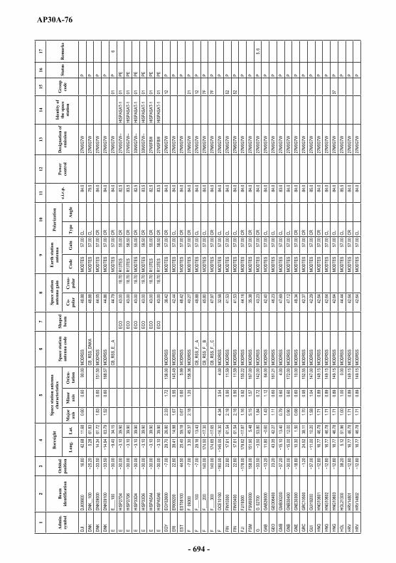
AP30A-76
12
34
56
78
910
1112
1314
1516
17
Adm
in.
sym
bol
Bea
m
iden
tific
atio
nO
rbita
l po
sitio
n
Bor
esig
htSp
ace
stat
ion
ante
nna
char
acte
rist
ics
Spac
e st
atio
n an
tenn
a co
deSh
aped
be
am
Spac
e st
atio
n an
tenn
aga
inE
arth
stat
ion
ante
nna
Pola
riza
tion
e.i.r
.p.
Pow
er
cont
rol
Des
igna
tion
of
emis
sion
Iden
tity
of
the
spac
e st
atio
n
Gro
up
code
Stat
usR
emar
ks
Lon
g.L
at.
Maj
or
axis
Min
or
axis
Ori
en-
tatio
nC
o-po
lar
Cro
ss-
pola
rC
ode
Gai
nT
ype
Ang
le
DJI
DJI09
900
16.80
42.68
11.68
0.60
0.60
90.00
MODR
SS
48.88
MODT
ES
57.00
CL84
.027
M0G7
W
PDN
KDN
K__1
005.2
861
.83CB
_RSS
_DNK
A 48
.88MO
DTES
57
.00CL
79.5
27M0
G7W
P
DNK
DNK0
9000
14.34
61.72
1.83
0.60
151.5
0MO
DRSS
44
.05MO
DTES
57
.00CR
84.0
27M0
G7W
P
DNK
DNK0
9100
63.79
1.52
0.60
168.5
7MO
DRSS
44
.86MO
DTES
57
.00CR
84.0
27M0
G7W
P
E
E___
_100
34.15
CB_R
SS_E
__A
44.79
MODT
ES
57.00
CR84
.027
M0G7
W
01P
6E
HI
SP27
D4.00
39.90
ECO
43.00
18.70
R13T
ES
55.00
CR82
.527
M0G7
W--
HISP
ASAT
-1
01PE
E
HISP
27D6
39.90
ECO
43.00
18.70
R13T
ES
58.50
CR83
.527
M0G7
W--
HISP
ASAT
-1
01PE
E
HISP
33D4
39.90
ECO
43.00
18.70
MODT
ES
55.00
CR82
.533
M0G7
W--
HISP
ASAT
-1
01PE
E
HISP
33D6
39.90
ECO
43.00
18.70
MODT
ES
58.50
CR83
.533
M0G7
W--
HISP
ASAT
-1
01PE
E
HISP
ASA4
39.90
ECO
43.00
18.70
R13T
ES
55.00
CR82
.527
M0F8
W
HISP
ASAT
-1
01PE
E
HISP
ASA6
39.90
ECO
43.00
18.70
R13T
ES
58.50
CR83
.527
M0F8
W
HISP
ASAT
-1
01PE
EGY
EGY0
2600
29.70
26.80
2.33
1.72
136.0
0MO
DRSS
38
.42MO
DTES
57
.00CR
84.0
27M0
G7W
12
PER
IER
I0920
022
.8039
.4114
.981.6
70.9
514
5.49
MODR
SS
42.44
MODT
ES
57.00
CL84
.027
M0G7
W
PES
TES
T061
0044
.5025
.4059
.180.6
70.6
05.9
9MO
DRSS
48
.42MO
DTES
57
.00CR
84.0
27M0
G7W
P
F
F 09
300
3.30
45.37
2.18
1.20
156.3
6MO
DRSS
40
.27MO
DTES
57
.00CR
84.0
27M0
G7W
21
PF
F_
___1
0029
.1613
.43CB
_RSS
_F__
A 48
.88MO
DTES
57
.00CL
84.0
27M0
G7W
12
PF
F_
___2
0014
0.00
174.5
0CB
_RSS
_F__
B 45
.80MO
DTES
57
.00CL
84.0
27M0
G7W
7F
PF
F_
___3
0014
0.00
174.6
5CB
_RSS
_F__
C 47
.97MO
DTES
57
.00CR
84.0
27M0
G7W
7F
PF
OC
E101
004.3
43.5
44.0
0MO
DRSS
32
.58MO
DTES
57
.00CL
84.0
27M0
G7W
P
FIN
FIN1
0300
22.80
17.61
61.54
2.18
0.90
11.59
MODR
SS
41.53
MODT
ES
57.00
CL84
.027
M0G7
W
52P
FIN
FIN1
0400
22.80
17.61
61.54
2.18
0.90
11.59
MODR
SS
41.53
MODT
ES
57.00
CL84
.027
M0G7
W
52P
FJI
FJI19
300
179.6
21.1
60.9
215
5.22
MODR
SS
44.16
MODT
ES
57.00
CR84
.027
M0G7
W
PFS
MFS
M000
0015
8.00
151.9
05.4
85.1
51.5
716
7.00
MODR
SS
35.38
MODT
ES
57.00
CR84
.027
M0G7
W
PG
G
0270
053
.801.8
40.7
214
2.00
MODR
SS
43.23
MODT
ES
57.00
CR84
.027
M0G7
W
P5,
6GA
BGA
B260
0011
.801.4
31.1
264
.00MO
DRSS
42
.40MO
DTES
57
.00CL
84.0
27M0
G7W
P
GEO
GEO0
6400
23.20
43.35
42.27
1.11
0.60
161.2
1MO
DRSS
46
.23MO
DTES
57
.00CL
84.0
27M0
G7W
P
GMB
GMB3
0200
13.40
0.79
0.60
4.00
MODR
SS
47.69
MODT
ES
57.00
CL83
.027
M0G7
W
PGN
BGN
B304
0012
.000.9
00.6
017
2.00
MODR
SS
47.12
MODT
ES
57.00
CL84
.027
M0G7
W
PGN
EGN
E303
0010
.301.5
00.6
80.6
010
.00MO
DRSS
48
.34MO
DTES
57
.00CR
84.0
27M0
G7W
P
GRC
GRC1
0500
.2024
.5238
.111.7
00.9
515
2.55
MODR
SS
42.37
MODT
ES
57.00
CR84
.027
M0G7
W
PGU
IGU
I1920
010
.201.5
81.0
414
7.00
MODR
SS
42.29
MODT
ES
57.00
CR85
.027
M0G7
W
PHN
GHN
G106
0116
.7746
.781.7
10.8
914
9.15
MODR
SS
42.64
MODT
ES
57.00
CR84
.027
M0G7
W
PHN
GHN
G106
0216
.7746
.781.7
10.8
914
9.15
MODR
SS
42.64
MODT
ES
57.00
CL84
.027
M0G7
W
PHN
GHN
G106
0316
.7746
.781.7
10.8
914
9.15
MODR
SS
42.64
MODT
ES
57.00
CL84
.027
M0G7
W
37P
HOL
HOL2
1300
38.20
5.12
51.96
1.00
1.00
0.00
MODR
SS
44.44
MODT
ES
57.00
CL85
.527
M0G7
W
PHR
VHR
V148
0116
.7746
.781.7
10.8
914
9.15
MODR
SS
42.64
MODT
ES
57.00
CR84
.027
M0G7
W
PHR
VHR
V148
0216
.7746
.781.7
10.8
914
9.15
MODR
SS
42.64
MODT
ES
57.00
CL84
.027
M0G7
W
P
- 694 -

AP30A-77
12
34
56
78
910
1112
1314
1516
17
Adm
in.
sym
bol
Bea
m
iden
tific
atio
nO
rbita
l po
sitio
n
Bor
esig
htSp
ace
stat
ion
ante
nna
char
acte
rist
ics
Spac
e st
atio
n an
tenn
a co
deSh
aped
be
am
Spac
e st
atio
n an
tenn
aga
inE
arth
stat
ion
ante
nna
Pola
riza
tion
e.i.r
.p.
Pow
er
cont
rol
Des
igna
tion
of
emis
sion
Iden
tity
of
the
spac
e st
atio
n
Gro
up
code
Stat
usR
emar
ks
Lon
g.L
at.
Maj
or
axis
Min
or
axis
Ori
en-
tatio
nC
o-po
lar
Cro
ss-
pola
rC
ode
Gai
nT
ype
Ang
le
HRV
HRV1
4803
16.77
46.78
1.71
0.89
149.1
5MO
DRSS
42
.64MO
DTES
57
.00CL
84.0
27M0
G7W
37
PI
I 082
009.0
012
.6740
.741.9
91.3
514
4.20
MODR
SS
40.14
MODT
ES
57.00
CR84
.027
M0G7
W
PIN
DIN
D037
0068
.0093
.0025
.501.4
61.1
340
.00MO
DRSS
42
.27MO
DTES
57
.00CL
84.0
27M0
G7W
P
IND
IND0
4701
68.00
93.30
11.10
1.92
0.60
96.00
MODR
SS
43.83
MODT
ES
57.00
CR84
.027
M0G7
W
7EP
IND
IND0
4702
68.00
93.30
11.10
1.92
0.60
96.00
MODR
SS
43.83
MODT
ES
57.00
CL84
.027
M0G7
W
7EP
IND
INDA
_101
55.80
76.16
14.72
CB_R
SS_IN
DA
45.66
MODT
ES
57.00
CR84
.027
M0G7
W
7GP
IND
INDA
_102
55.80
76.16
14.72
CB_R
SS_IN
DA
45.66
MODT
ES
57.00
CL84
.027
M0G7
W
7GP
IND
INDB
_101
55.80
83.67
23.73
CB_R
SS_IN
DB
43.13
MODT
ES
57.00
CR84
.027
M0G7
W
7HP
IND
INDB
_102
55.80
83.67
23.73
CB_R
SS_IN
DB
43.13
MODT
ES
57.00
CL84
.027
M0G7
W
7HP
IND
INDD
_100
68.00
74.37
29.16
CB_R
SS_IN
DD
41.79
MODT
ES
57.00
CR84
.027
M0G7
W
PIN
SIN
S028
0080
.2011
3.60
6.73
3.33
160.0
0MO
DRSS
30
.94MO
DTES
57
.00CR
84.0
27M0
G7W
P
INS
INS0
3501
104.0
011
5.20
9.14
3.43
170.0
0MO
DRSS
29
.48MO
DTES
57
.00CL
84.0
27M0
G7W
7D
PIN
SIN
S035
0210
4.00
115.2
09.1
43.4
317
0.00
MODR
SS
29.48
MODT
ES
57.00
CR84
.027
M0G7
W
7DP
IRL
IRL2
1100
53.22
0.72
0.60
157.5
6MO
DRSS
48
.08MO
DTES
57
.00CR
84.0
27M0
G7W
P
IRN
IRN1
0900
34.00
54.20
32.40
3.82
1.82
149.0
0MO
DRSS
36
.03MO
DTES
57
.00CL
83.0
27M0
G7W
P
ISL
ISL0
4900
64.90
1.00
0.60
177.0
0MO
DRSS
46
.67MO
DTES
57
.00CL
83.0
27M0
G7W
P
ISL
ISL0
5000
63.79
1.52
0.60
168.5
7MO
DRSS
44
.86MO
DTES
57
.00CR
84.0
27M0
G7W
P
ISR
ISR1
1000
34.95
31.32
0.73
0.60
110.0
2MO
DRSS
48
.03MO
DTES
57
.00CR
84.0
27M0
G7W
P
J 10
9.85
134.5
031
.503.5
23.3
068
.00MO
DRSS
33
.80MO
DTES
57
.00CR
87.0
27M0
F8W
BS
-3N
02
PEJ
J 10
985
109.8
513
4.50
31.50
3.52
3.30
68.00
MODR
SS
33.80
MODT
ES
57.00
CR87
.034
M5G7
W
02P
J J
1110
011
0.00
134.5
031
.503.5
23.3
068
.00MO
DRSS
33
.80MO
DTES
57
.00CR
87.0
34M5
G7W
02
PJ
J 11
10E
110.0
013
4.50
31.50
3.52
3.30
68.00
MODR
SS
33.80
MODT
ES
57.00
CR87
.027
M0F8
W
BS-3
M
02PE
JOR
JOR2
2400
11.00
37.55
34.02
1.47
0.91
73.16
MODR
SS
43.19
MODT
ES
57.00
CL85
.027
M0G7
W
PKA
ZKA
Z066
0056
.4065
.7346
.404.5
81.7
617
7.45
MODR
SS
35.38
MODT
ES
57.00
CL84
.027
M0G7
W
PKE
NKE
N249
0037
.990.8
82.0
61.3
099
.68MO
DRSS
40
.17MO
DTES
57
.00CR
84.0
27M0
G7W
P
KGZ
KGZ0
7000
50.00
73.91
41.32
1.47
0.64
5.05
MODR
SS
44.75
MODT
ES
57.00
CR84
.027
M0G7
W
PKI
RKI
R__1
0017
6.00
CB_R
SS_K
IRA
42.60
MODT
ES
57.00
CL84
.027
M0G7
W
PKO
RKO
R112
0111
6.00
127.5
036
.001.2
41.0
216
8.00
MODR
SS
43.43
MODT
ES
57.00
CL89
.027
M0G7
W
03P
KOR
KOR1
1202
116.0
012
7.50
36.00
1.24
1.02
168.0
0MO
DRSS
43
.43MO
DTES
57
.00CR
89.0
27M0
G7W
03
PKR
EKR
E286
0014
0.00
128.4
540
.321.6
30.6
818
.89MO
DRSS
44
.00MO
DTES
57
.00CL
87.0
27M0
G7W
P
KWT
KWT1
1300
11.00
47.48
29.12
0.60
0.60
90.00
MODR
SS
48.88
MODT
ES
57.00
CR83
.027
M0G7
W
PLA
OLA
O284
0012
2.20
103.7
118
.171.8
71.0
312
3.99
MODR
SS
42.18
MODT
ES
57.00
CR84
.033
M0G7
W
PLB
NLB
N279
0011
.0037
.5534
.021.4
70.9
173
.16MO
DRSS
43
.19MO
DTES
57
.00CR
84.0
27M0
G7W
P
LBR
LBR2
4400
6.60
1.22
0.70
133.0
0MO
DRSS
45
.13MO
DTES
57
.00CR
84.0
27M0
G7W
P
5, 6
LBY
LBY2
8021
17.50
26.30
3.68
1.84
130.0
0MO
DRSS
36
.14MO
DTES
57
.00CL
84.0
27M0
G7W
P
LIELIE
2530
010
.3149
.471.8
20.9
215
1.78
MODR
SS
42.19
MODT
ES
57.00
CL84
.027
M0G7
W
PLS
OLS
O305
004.8
027
.800.6
60.6
036
.00MO
DRSS
48
.47MO
DTES
57
.00CL
84.0
27M0
G7W
P
- 695 -

AP30A-78
12
34
56
78
910
1112
1314
1516
17
Adm
in.
sym
bol
Bea
m
iden
tific
atio
nO
rbita
l po
sitio
n
Bor
esig
htSp
ace
stat
ion
ante
nna
char
acte
rist
ics
Spac
e st
atio
n an
tenn
a co
deSh
aped
be
am
Spac
e st
atio
n an
tenn
aga
inE
arth
stat
ion
ante
nna
Pola
riza
tion
e.i.r
.p.
Pow
er
cont
rol
Des
igna
tion
of
emis
sion
Iden
tity
of
the
spac
e st
atio
n
Gro
up
code
Stat
usR
emar
ks
Lon
g.L
at.
Maj
or
axis
Min
or
axis
Ori
en-
tatio
nC
o-po
lar
Cro
ss-
pola
rC
ode
Gai
nT
ype
Ang
le
LTU
LTU0
6100
23.20
24.52
56.11
CB_R
SS_L
TUA
47.92
MODT
ES
57.00
CR84
.027
M0G7
W
PLU
XLU
X114
0028
.205.2
149
.200.6
00.6
090
.00MO
DRSS
48
.88MO
DTES
57
.00CL
84.0
27M0
G7W
09
PLV
ALV
A061
0023
.2024
.5256
.11CB
_RSS
_LVA
A 47
.92MO
DTES
57
.00CR
84.0
27M0
G7W
P
MAU
MAU_
_100
29.00
58.61
CB_R
SS_M
AUA
41.42
MODT
ES
57.00
CL84
.027
M0G7
W
P
MCO
MCO1
1600
34.20
7.40
43.70
0.60
0.60
0.00
MODR
SS
48.88
MODT
ES
57.00
CR81
.027
M0G7
W
PMD
AMD
A063
0050
.0028
.4546
.990.6
00.6
090
.00MO
DRSS
48
.88MO
DTES
57
.00CR
84.0
27M0
G7W
P
MDG
MDG2
3600
29.00
46.20
2.57
0.80
67.00
MODR
SS
41.32
MODT
ES
57.00
CL84
.027
M0G7
W
PMH
LMH
L000
0014
6.00
167.6
49.8
32.0
70.9
015
7.42
MODR
SS
41.75
MODT
ES
57.00
CR84
.027
M0G7
W
PMK
DMK
D148
0022
.8021
.5341
.500.6
00.6
090
.00MO
DRSS
48
.88MO
DTES
57
.00CL
84.0
27M0
G7W
P
MLA
MLA_
_100
91.50
108.0
73.9
2CB
_RSS
_MLA
A 41
.75MO
DTES
57
.00CR
84.0
27M0
G7W
P
MLD
MLD3
0600
50.00
73.10
6.00
0.60
0.60
0.00
MODR
SS
48.88
MODT
ES
57.00
CR84
.027
M0G7
W
PML
IML
I__10
016
.10CB
_RSS
_MLIA
41
.11MO
DTES
57
.00CR
87.0
27M0
G7W
P
MLT
MLT1
4700
22.80
14.40
35.90
0.60
0.60
0.00
MODR
SS
48.88
MODT
ES
57.00
CR84
.027
M0G7
W
PMN
GMN
G248
0074
.0010
1.95
46.79
3.32
1.04
169.2
7MO
DRSS
39
.07MO
DTES
59
.92CL
86.9
27M0
G7W
P
MRC
MRC2
0900
28.90
3.96
1.55
50.00
MODR
SS
36.57
MODT
ES
57.00
CR80
.027
M0G7
W
PMT
NMT
N__1
0020
.91CB
_RSS
_MTN
A 37
.55MO
DTES
57
.00CR
86.0
27M0
G7W
P
MWI
MWI30
800
4.80
33.79
1.56
0.70
92.69
MODR
SS
44.10
MODT
ES
57.00
CR84
.027
M0G7
W
PNG
RNG
R115
007.6
316
.972.2
01.8
010
0.58
MODR
SS
38.47
MODT
ES
57.00
CL84
.027
M0G7
W
PNO
RNO
R120
0016
.7061
.581.8
40.9
517
7.31
MODR
SS
42.02
MODT
ES
57.00
CR84
.027
M0G7
W
06P
NOR
NOR1
2100
16.70
61.58
1.84
0.95
177.3
1MO
DRSS
42
.02MO
DTES
57
.00CL
84.0
27M0
G7W
06
PNR
UNR
U309
0013
4.00
167.0
00.6
00.6
00.0
0MO
DRSS
48
.88MO
DTES
57
.00CL
84.0
27M0
G7W
P
NZL
NZL_
_100
158.0
0CB
_RSS
_NZL
A 48
.88MO
DTES
57
.00CL
84.0
27M0
G7W
P
OMA
OMA1
2300
17.20
55.60
21.00
1.88
1.02
100.0
0MO
DRSS
41
.62MO
DTES
57
.00CL
85.0
27M0
G7W
P
PHL
PHL2
8500
98.00
121.3
011
.103.4
61.7
699
.00MO
DRSS
36
.60MO
DTES
57
.00CL
84.0
27M0
G7W
P
PLW
PLW
0000
014
0.00
132.9
85.5
11.3
00.6
055
.41MO
DRSS
45
.53MO
DTES
57
.00CR
84.0
27M0
G7W
P
POL
POL1
3200
50.00
19.71
52.18
1.22
0.63
16.12
MODR
SS
45.59
MODT
ES
57.00
CR84
.027
M0G7
W
PPO
RPO
R__1
0037
.65CB
_RSS
_POR
A 47
.17MO
DTES
57
.00CR
84.0
27M0
G7W
P
PSE
YYY0
0001
34.99
31.86
0.60
0.60
90.00
MODR
SS
48.88
MODT
ES
57.00
CL80
.527
M0G7
W
P8
QAT
QAT2
4700
20.00
51.59
25.35
0.60
0.60
90.00
MODR
SS
48.88
MODT
ES
57.00
CL84
.027
M0G7
W
PRO
URO
U136
0050
.0025
.1245
.751.1
70.7
39.5
2MO
DRSS
45
.15MO
DTES
57
.00CL
84.0
27M0
G7W
P
RRW
RRW
3100
011
.0030
.000.6
60.6
042
.00MO
DRSS
48
.47MO
DTES
57
.00CR
81.0
27M0
G7W
P
RUS
RSTR
EA11
36.00
38.00
53.00
COP
38.40
8.40
MODT
ES
57.00
CR84
.027
M0F8
W
RST-
1
05PE
RUS
RSTR
EA12
36.00
38.00
53.00
COP
38.40
8.40
MODT
ES
57.00
CL84
.027
M0F8
W
RST-
1
05PE
RUS
RSTR
ED11
36.00
38.00
53.00
COP
38.40
8.40
MODT
ES
57.00
CR84
.027
M0G7
W
RST-
1
05PE
RUS
RSTR
ED12
36.00
38.00
53.00
COP
38.40
8.40
MODT
ES
57.00
CL84
.027
M0G7
W
RST-
1
05PE
RUS
RSTR
SD11
36.00
38.00
53.00
COP
38.40
8.40
MODT
ES
57.00
CR84
.027
M0G7
W
RST-
1
05P
RUS
RSTR
SD12
36.00
38.00
53.00
COP
38.40
8.40
MODT
ES
57.00
CL84
.027
M0G7
W
RST-
1
05P
- 696 -

AP30A-79
12
34
56
78
910
1112
1314
1516
17
Adm
in.
sym
bol
Bea
m
iden
tific
atio
nO
rbita
l po
sitio
n
Bor
esig
htSp
ace
stat
ion
ante
nna
char
acte
rist
ics
Spac
e st
atio
n an
tenn
a co
deSh
aped
be
am
Spac
e st
atio
n an
tenn
aga
inE
arth
stat
ion
ante
nna
Pola
riza
tion
e.i.r
.p.
Pow
er
cont
rol
Des
igna
tion
of
emis
sion
Iden
tity
of
the
spac
e st
atio
n
Gro
up
code
Stat
usR
emar
ks
Lon
g.L
at.
Maj
or
axis
Min
or
axis
Ori
en-
tatio
nC
o-po
lar
Cro
ss-
pola
rC
ode
Gai
nT
ype
Ang
le
RUS
RSTR
SD21
56.00
65.00
63.00
COP
38.40
8.40
MODT
ES
57.00
CR84
.027
M0G7
W
RST-
2
14P
RUS
RSTR
SD22
56.00
65.00
63.00
COP
38.40
8.40
MODT
ES
57.00
CL84
.027
M0G7
W
RST-
2
14P
RUS
RSTR
SD31
86.00
97.00
62.00
COP
38.40
8.40
MODT
ES
57.00
CR84
.027
M0G7
W
RST-
3
33P
RUS
RSTR
SD32
86.00
97.00
62.00
COP
38.40
8.40
MODT
ES
57.00
CL84
.027
M0G7
W
RST-
3
33P
RUS
RSTR
SD51
140.0
015
8.00
56.00
COP
38.40
8.40
MODT
ES
57.00
CR84
.027
M0G7
W
RST-
5
35P
RUS
RSTR
SD52
140.0
015
8.00
56.00
COP
38.40
8.40
MODT
ES
57.00
CL84
.027
M0G7
W
RST-
5
35P
RUS
RUS0
0401
110.0
011
8.22
51.52
COP
38.40
8.40
MODT
ES
57.00
CR84
.027
M0G7
W
RUS-
4
34P
RUS
RUS0
0402
110.0
011
8.22
51.52
COP
38.40
8.40
MODT
ES
57.00
CL84
.027
M0G7
W
RUS-
4
34P
S
S 13
800
5.00
17.00
61.50
2.00
1.00
10.00
MODR
SS
41.44
MODT
ES
57.00
CL84
.027
M0G7
W
04P
S
S 13
900
5.00
17.00
61.50
2.00
1.00
10.00
MODR
SS
41.44
MODT
ES
57.00
CL84
.027
M0G7
W
04P
SEY
SEY0
0000
42.50
51.86
2.43
1.04
27.51
MODR
SS
40.44
MODT
ES
57.00
CR84
.027
M0G7
W
PSL
MSL
M000
0012
8.00
159.2
71.3
51.0
811
8.59
MODR
SS
42.81
MODT
ES
57.00
CL84
.027
M0G7
W
PSM
OSM
O057
000.6
00.6
090
.00MO
DRSS
48
.88MO
DTES
57
.00CL
84.0
27M0
G7W
P
SMR
SMR3
1100
12.50
43.90
0.60
0.60
0.00
MODR
SS
48.88
MODT
ES
57.00
CL83
.027
M0G7
W
P
SNG
SNG1
5100
88.00
103.8
61.4
20.9
20.7
217
5.12
MODR
SS
46.25
MODT
ES
57.00
CL84
.027
M0G7
W
PSR
BSR
B148
0020
.5043
.980.9
10.6
014
5.16
MODR
SS
47.07
MODT
ES
57.00
CL84
.027
M0G7
W
PSR
LSR
L259
000
8.60
0.78
0.68
114.0
0MO
DRSS
47
.20MO
DTES
57
.00CR
84.0
27M0
G7W
P
STP
STP2
4100
7.00
0.80
0.60
0.60
0.00
MODR
SS
48.88
MODT
ES
57.00
CL84
.027
M0G7
W
PSU
ISU
I1400
010
.3149
.471.8
20.9
215
1.78
MODR
SS
42.19
MODT
ES
57.00
CL84
.027
M0G7
W
PSV
KSV
K144
0116
.7746
.781.7
10.8
914
9.15
MODR
SS
42.64
MODT
ES
57.00
CR84
.027
M0G7
W
PSV
KSV
K144
0216
.7746
.781.7
10.8
914
9.15
MODR
SS
42.64
MODT
ES
57.00
CL84
.027
M0G7
W
PSV
KSV
K144
0316
.7746
.781.7
10.8
914
9.15
MODR
SS
42.64
MODT
ES
57.00
CL84
.027
M0G7
W
37P
SVN
SVN1
4800
33.80
15.01
46.18
0.60
0.60
90.00
MODR
SS
48.88
MODT
ES
57.00
CR82
.027
M0G7
W
PSW
ZSW
Z313
004.8
031
.390.6
00.6
090
.00MO
DRSS
48
.88MO
DTES
57
.00CR
82.0
27M0
G7W
P
SYR
SYR2
2900
11.00
37.55
34.02
1.47
0.91
73.16
MODR
SS
43.19
MODT
ES
57.00
CL84
.027
M0G7
W
53P
SYR
SYR3
3900
11.00
37.60
34.20
1.32
0.88
74.00
MODR
SS
43.80
MODT
ES
57.00
CL84
.027
M0G7
W
53P
TCD
TCD1
4300
17.00
18.39
15.52
3.21
2.05
83.26
MODR
SS
36.26
MODT
ES
57.00
CR84
.027
M0G7
W
PTH
ATH
A142
0098
.0010
0.75
12.88
2.80
1.82
93.77
MODR
SS
37.38
MODT
ES
57.00
CR84
.027
M0G7
W
PTJ
KTJ
K069
0038
.0071
.1438
.411.2
10.7
315
5.31
MODR
SS
45.00
MODT
ES
57.00
CL82
.027
M0G7
W
PTK
MTK
M068
0050
.0059
.2438
.832.2
61.0
216
6.64
MODR
SS
40.81
MODT
ES
57.00
CL85
.727
M0G7
W
PTL
STL
S000
0012
8.00
126.0
30.6
60.6
013
.92MO
DRSS
48
.50MO
DTES
57
.00CR
84.0
27M0
G7W
P
TON
TON2
1500
170.7
51.5
90.6
071
.33MO
DRSS
44
.64MO
DTES
57
.00CR
84.0
27M0
G7W
P
TUN
TUN1
5000
9.50
33.50
1.88
0.72
135.0
0MO
DRSS
43
.13MO
DTES
57
.00CR
84.0
27M0
G7W
55
PTU
NTU
N272
002.5
032
.003.5
91.7
517
5.00
MODR
SS
36.47
MODT
ES
57.00
CR84
.027
M0G7
W
55P
TUR
TUR1
4500
42.00
35.14
38.99
3.19
1.10
0.03
MODR
SS
39.00
MODT
ES
57.00
CL84
.027
M0G7
W
36P
TUV
TUV0
0000
176.0
017
7.61
0.94
0.60
137.5
8MO
DRSS
46
.93MO
DTES
57
.00CR
84.0
27M0
G7W
P
TZA
TZA2
2500
11.00
34.60
2.41
1.72
129.0
0MO
DRSS
38
.27MO
DTES
57
.00CR
84.0
27M0
G7W
P
- 697 -
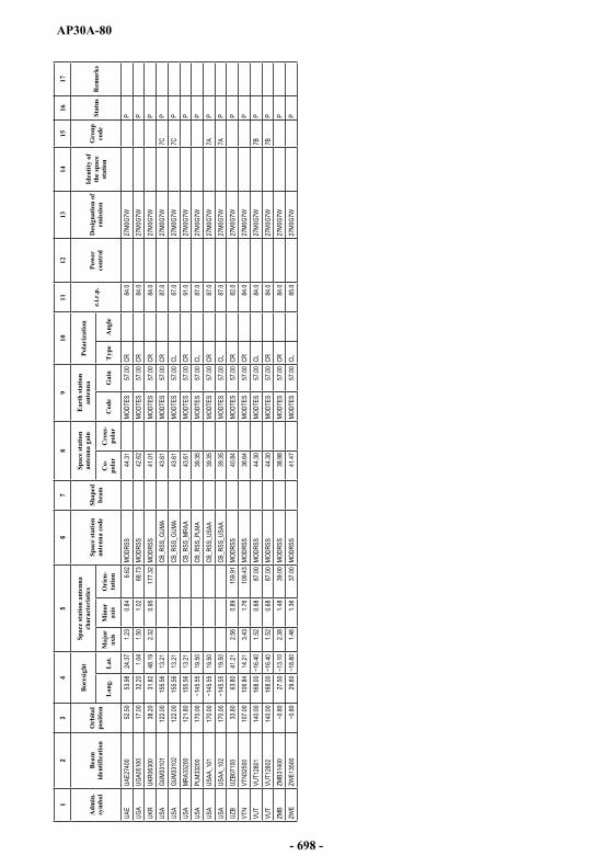
AP30A-80
12
34
56
78
910
1112
1314
1516
17
Adm
in.
sym
bol
Bea
m
iden
tific
atio
nO
rbita
l po
sitio
n
Bor
esig
htSp
ace
stat
ion
ante
nna
char
acte
rist
ics
Spac
e st
atio
n an
tenn
a co
deSh
aped
be
am
Spac
e st
atio
n an
tenn
aga
inE
arth
stat
ion
ante
nna
Pola
riza
tion
e.i.r
.p.
Pow
er
cont
rol
Des
igna
tion
of
emis
sion
Iden
tity
of
the
spac
e st
atio
n
Gro
up
code
Stat
usR
emar
ks
Lon
g.L
at.
Maj
or
axis
Min
or
axis
Ori
en-
tatio
nC
o-po
lar
Cro
ss-
pola
rC
ode
Gai
nT
ype
Ang
le
UAE
UAE2
7400
52.50
53.98
24.37
1.23
0.84
6.62
MODR
SS
44.31
MODT
ES
57.00
CR84
.027
M0G7
W
PUG
AUG
A051
0017
.0032
.201.0
41.5
01.0
268
.73MO
DRSS
42
.62MO
DTES
57
.00CR
84.0
27M0
G7W
P
UKR
UKR0
6300
38.20
31.82
48.19
2.32
0.95
177.3
2MO
DRSS
41
.01MO
DTES
57
.00CR
84.0
27M0
G7W
P
USA
GUM3
3101
122.0
015
5.56
13.21
CB_R
SS_G
UMA
43.61
MODT
ES
57.00
CR87
.027
M0G7
W
7CP
USA
GUM3
3102
122.0
015
5.56
13.21
CB_R
SS_G
UMA
43.61
MODT
ES
57.00
CL87
.027
M0G7
W
7CP
USA
MRA3
3200
121.8
015
5.56
13.21
CB_R
SS_M
RAA
43.61
MODT
ES
57.00
CR91
.027
M0G7
W
PUS
APL
M332
0017
0.00
19.50
CB_R
SS_P
LMA
39.35
MODT
ES
57.00
CL87
.027
M0G7
W
PUS
AUS
AA_1
0117
0.00
19.50
CB_R
SS_U
SAA
39.35
MODT
ES
57.00
CR87
.027
M0G7
W
7AP
USA
USAA
_102
170.0
019
.50CB
_RSS
_USA
A 39
.35MO
DTES
57
.00CL
87.0
27M0
G7W
7A
PUZ
BUZ
B071
0033
.8063
.8041
.212.5
60.8
915
9.91
MODR
SS
40.84
MODT
ES
57.00
CR82
.027
M0G7
W
PVT
NVT
N325
0010
7.00
106.8
414
.213.4
31.7
610
9.43
MODR
SS
36.64
MODT
ES
57.00
CR84
.027
M0G7
W
PVU
TVU
T128
0114
0.00
168.0
01.5
20.6
887
.00MO
DRSS
44
.30MO
DTES
57
.00CL
84.0
27M0
G7W
7B
PVU
TVU
T128
0214
0.00
168.0
01.5
20.6
887
.00MO
DRSS
44
.30MO
DTES
57
.00CR
84.0
27M0
G7W
7B
PZM
BZM
B314
0027
.502.3
81.4
839
.00MO
DRSS
38
.98MO
DTES
57
.00CR
84.0
27M0
G7W
P
ZWE
ZWE1
3500
29.60
1.46
1.36
37.00
MODR
SS
41.47
MODT
ES
57.00
CL85
.027
M0G7
W
P
- 698 -
AP30A-81
COLUMN HEADINGS OF TABLES 3B1 AND 3B2
Col. 1 Nominal orbital position, in degrees and hundredths of a degree from the Greenwich meridian (negative values indicate longitudes which are west of the Greenwich meridian; positive values indicate longitudes which are east of the Greenwich meridian).
Col. 2 Notifying administration symbol.
Col. 3 Beam identification (Column 2, normally, contains the symbol designating the administration or the geographical area taken from Table B1 of the Preface to the International Frequency List, followed by the symbol designating the service area).
Col. 4 Polarization (CL circular left, CR circular right).
Col. 5 Channel number/indication of minimum equivalent protection margin (EPM) for a given assignment derived from the set of values for all test points belonging to the given beam.
- 699 -
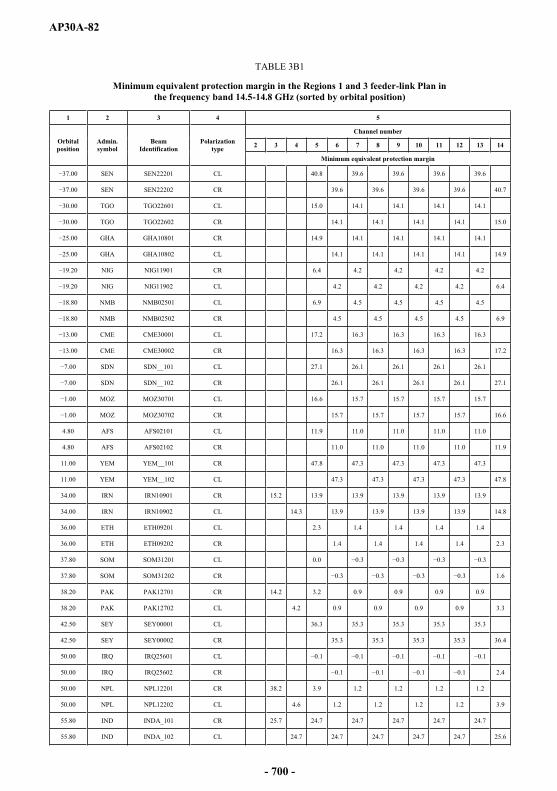
AP30A-82
TABLE 3B1
Minimum equivalent protection margin in the Regions 1 and 3 feeder-link Plan in the frequency band 14.5-14.8 GHz (sorted by orbital position)
1 2 3 4 5
Orbital position
Admin.symbol
BeamIdentification
Polarizationtype
Channel number
2 3 4 5 6 7 8 9 10 11 12 13 14
Minimum equivalent protection margin
SEN SEN22201 CL 40.8 39.6 39.6 39.6 39.6
SEN SEN22202 CR 39.6 39.6 39.6 39.6 40.7
TGO TGO22601 CL 15.0 14.1 14.1 14.1 14.1
TGO TGO22602 CR 14.1 14.1 14.1 14.1 15.0
GHA GHA10801 CR 14.9 14.1 14.1 14.1 14.1
GHA GHA10802 CL 14.1 14.1 14.1 14.1 14.9
NIG NIG11901 CR 6.4 4.2 4.2 4.2 4.2
NIG NIG11902 CL 4.2 4.2 4.2 4.2 6.4
NMB NMB02501 CL 6.9 4.5 4.5 4.5 4.5
NMB NMB02502 CR 4.5 4.5 4.5 4.5 6.9
CME CME30001 CL 17.2 16.3 16.3 16.3 16.3
CME CME30002 CR 16.3 16.3 16.3 16.3 17.2
SDN SDN__101 CL 27.1 26.1 26.1 26.1 26.1
0 SDN SDN__102 CR 26.1 26.1 26.1 26.1 27.1
MOZ MOZ30701 CL 16.6 15.7 15.7 15.7 15.7
MOZ MOZ30702 CR 15.7 15.7 15.7 15.7 16.6
4.80 AFS AFS02101 CL 11.9 11.0 11.0 11.0 11.0
4.80 AFS AFS02102 CR 11.0 11.0 11.0 11.0 11.9
11.00 YEM YEM__101 CR 47.8 47.3 47.3 47.3 47.3
11.00 YEM YEM__102 CL 47.3 47.3 47.3 47.3 47.8
34.00 IRN IRN10901 CR 15.2 13.9 13.9 13.9 13.9 13.9
34.00 IRN IRN10902 CL 14.3 13.9 13.9 13.9 13.9 14.8
36.00 ETH ETH09201 CL 2.3 1.4 1.4 1.4 1.4
36.00 ETH ETH09202 CR 1.4 1.4 1.4 1.4 2.3
37.80 SOM SOM31201 CL 0.0
37.80 SOM SOM31202 CR 1.6
38.20 PAK PAK12701 CR 14.2 3.2 0.9 0.9 0.9 0.9
38.20 PAK PAK12702 CL 4.2 0.9 0.9 0.9 0.9 3.3
42.50 SEY SEY00001 CL 36.3 35.3 35.3 35.3 35.3
42.50 SEY SEY00002 CR 35.3 35.3 35.3 35.3 36.4
50.00 IRQ IRQ25601 CL
50.00 IRQ IRQ25602 CR 2.4
50.00 NPL NPL12201 CR 38.2 3.9 1.2 1.2 1.2 1.2
50.00 NPL NPL12202 CL 4.6 1.2 1.2 1.2 1.2 3.9
55.80 IND INDA_101 CR 25.7 24.7 24.7 24.7 24.7 24.7
55.80 IND INDA_102 CL 24.7 24.7 24.7 24.7 24.7 25.6
- 700 -
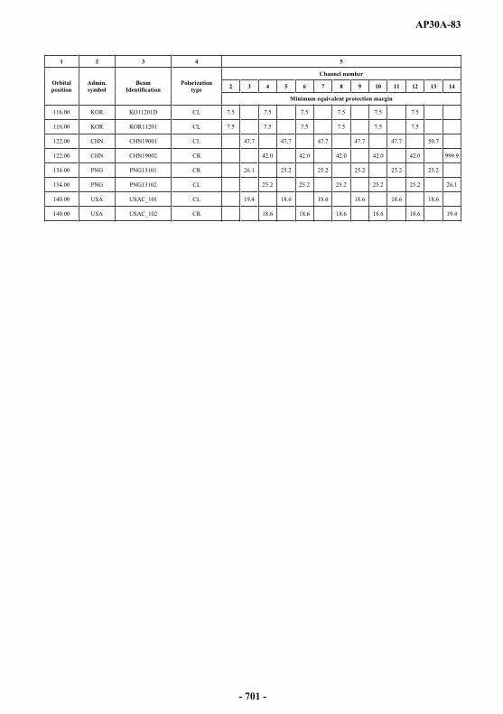
AP30A-83
1 2 3 4 5
Orbital position
Admin.symbol
BeamIdentification
Polarizationtype
Channel number
2 3 4 5 6 7 8 9 10 11 12 13 14
Minimum equivalent protection margin
116.00 KOR KO11201D CL 7.5 7.5 7.5 7.5 7.5 7.5
116.00 KOR KOR11201 CL 7.5 7.5 7.5 7.5 7.5 7.5
122.00 CHN CHN19001 CL 47.7 47.7 47.7 47.7 47.7 50.7
122.00 CHN CHN19002 CR 42.0 42.0 42.0 42.0 42.0 999.9
134.00 PNG PNG13101 CR 26.1 25.2 25.2 25.2 25.2 25.2
134.00 PNG PNG13102 CL 25.2 25.2 25.2 25.2 25.2 26.1
140.00 USA USAC_101 CL 19.4 18.6 18.6 18.6 18.6 18.6
140.00 USA USAC_102 CR 18.6 18.6 18.6 18.6 18.6 19.4
- 701 -
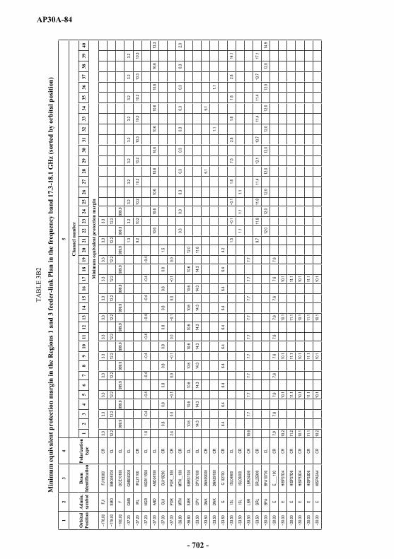
AP30A-84
TAB
LE 3
B2
Min
imum
equ
ival
ent p
rote
ctio
n m
argi
n in
the
Reg
ions
1 a
nd 3
feed
er-li
nk P
lan
in th
e fr
eque
ncy
band
17.
3-18
.1 G
Hz
(sor
ted
by o
rbita
l pos
ition
)
12
34
5
Orb
ital
Posi
tion
Adm
in.
sym
bol
Bea
m
Iden
tific
atio
nPo
lari
zatio
n ty
pe
Cha
nnel
num
ber
12
34
56
78
910
1112
1314
1516
1718
1920
2122
2324
2526
2728
2930
3132
3334
3536
3738
3940
Min
imum
equ
ival
ent p
rote
ctio
n m
argi
n
178.0
0FJ
IFJ
I1930
0CR
3.33.3
3.33.3
3.33.3
3.33.3
3.33.3
3.33.3
SMO
SMO0
5700
CL12
.212
.212
.212
.212
.212
.212
.212
.212
.212
.212
.212
.2
F
OCE1
0100
CL99
9.999
9.999
9.999
9.999
9.999
9.999
9.999
9.999
9.999
9.999
9.999
9.9
GMB
GMB3
0200
CL1.3
3.23.2
3.23.2
3.23.2
3.23.2
3.2
IRL
IRL2
1100
CR9.2
10.2
10.2
10.2
10.2
10.3
10.2
10.2
10.3
10.3
NGR
NGR1
1500
CL1.8
AND
AND3
4100
CL10
.610
.610
.610
.610
.610
.610
.610
.610
.613
.3
GUI
GUI19
200
CR0.8
0.80.8
0.80.8
0.80.8
0.80.8
1.5
POR
POR_
_100
CR2.4
0.00.0
0.00.0
0.0
MTN
MTN_
_100
CR0.3
0.30.3
0.30.3
0.30.3
0.30.3
2.0
SMR
SMR3
1100
CL10
.610
.610
.610
.610
.610
.610
.610
.610
.612
.0
CPV
CPV3
0100
CL14
.314
.314
.314
.314
.314
.314
.314
.314
.311
.6
DNK
DNK0
9000
CR5.1
5.1
DNK
DNK0
9100
CR1.1
1.1
G
G 02
700
CR6.4
6.46.4
6.46.4
6.46.4
6.46.4
4.2
ISL
ISL0
4900
CL1.5
1.87.5
2.81.8
1.82.8
14.1
ISL
ISL0
5000
CR1.1
1.11.1
LBR
LBR2
4400
CR10
.67.7
7.77.7
7.77.7
7.77.7
7.77.7
SRL
SRL2
5900
CR9.7
11.8
11.8
11.4
13.1
13.7
11.4
11.4
13.7
17.1
BFA
BFA1
0700
CL12
.012
.012
.012
.012
.012
.012
.012
.012
.014
.9
EE_
___1
00CR
7.97.6
7.67.6
7.67.6
7.67.6
7.67.6
EHI
SP27
D4CR
10.2
10.1
10.1
10.1
10.1
EHI
SP27
D6CR
11.2
11.1
11.1
11.1
11.1
EHI
SP33
D4CR
10.1
10.1
10.1
10.1
10.1
EHI
SP33
D6CR
11.1
11.1
11.1
11.1
11.1
EHI
SPAS
A4CR
10.2
10.1
10.1
10.1
10.1
- 702 -
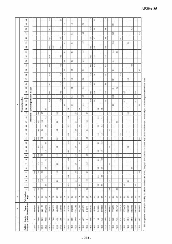
AP30A-85
12
34
5
Orb
ital
Posi
tion
Adm
in.
sym
bol
Bea
m
Iden
tific
atio
nPo
lari
zatio
n ty
pe
Cha
nnel
num
ber
12
34
56
78
910
1112
1314
1516
1718
1920
2122
2324
2526
2728
2930
3132
3334
3536
3738
3940
Min
imum
equ
ival
ent p
rote
ctio
n m
argi
n
EHI
SPAS
A6CR
11.2
11.1
11.1
11.1
11.1
GNB
GNB3
0400
CL15
.616
.915
.216
.915
.216
.915
.216
.915
.216
.9
DNK
DNK_
_100
CL1.2
MRC
MRC2
0900
CR1.1
1.11.1
1.11.1
1.11.1
1.11.1
TUN
TUN1
5000
CR
TUN
TUN2
7200
CR
AGL
AGL2
9500
CR9.2
6.86.8
6.86.8
6.86.8
6.86.8
6.8
ALG
ALG2
5152
CL0.0
CTI
CTI23
700
CR6.5
5.55.5
5.55.5
5.55.3
5.25.3
5.2
LBY
LBY2
8021
CL0.6
BEN
BEN2
3300
CL4.4
9.49.4
9.49.4
9.49.4
9.49.4
9.4
COD
COD_
_100
CL4.5
2.12.1
2.12.1
2.12.1
2.12.1
2.1
MLI
MLI__
100
CR4.2
4.24.2
4.24.2
4.24.2
4.24.2
2.4
AUT
AUT0
1600
CR
D
D 08
700
CR2.5
GNE
GNE3
0300
CR13
.013
.013
.013
.013
.013
.013
.013
.013
.014
.7
LIELIE
2530
0CL
0.00.0
0.00.0
0.00.0
0.00.0
0.02.5
SUI
SUI14
000
CL0.3
0.30.3
0.30.3
0.30.3
0.30.3
0.3
CAF
CAF2
5800
CR1.1
1.11.1
1.11.1
1.0
COG
COG2
3500
CR9.8
9.89.8
9.89.8
9.89.8
9.89.8
11.7
GAB
GAB2
6000
CL4.9
1.71.7
1.71.7
1.71.7
1.71.7
1.7
PSE
YYY0
0001
CL8.6
10.1
10.1
10.1
10.1
10.1
10.1
10.1
10.1
10.1
CZE
CZE1
4401
CR2.8
0.80.8
0.00.0
CZE
CZE1
4402
CL0.1
CZE
CZE1
4403
CL0.1
*
HNG
HNG1
0601
CR0.8
0.80.8
0.00.0
HNG
HNG1
0602
CL0.1
HNG
HNG1
0603
CL0.1
*
HRV
HRV1
4801
CR0.8
0.80.8
0.00.0
*Th
is as
sign
men
t sha
ll on
ly b
e us
ed b
y th
e ad
min
istra
tions
of C
roat
ia, H
unga
ry, S
lova
kia
and
the
Cze
ch R
ep. o
n th
e ba
sis o
f equ
al a
cces
s sub
ject
to m
utua
l agr
eem
ent b
etw
een
them
.
- 703 -
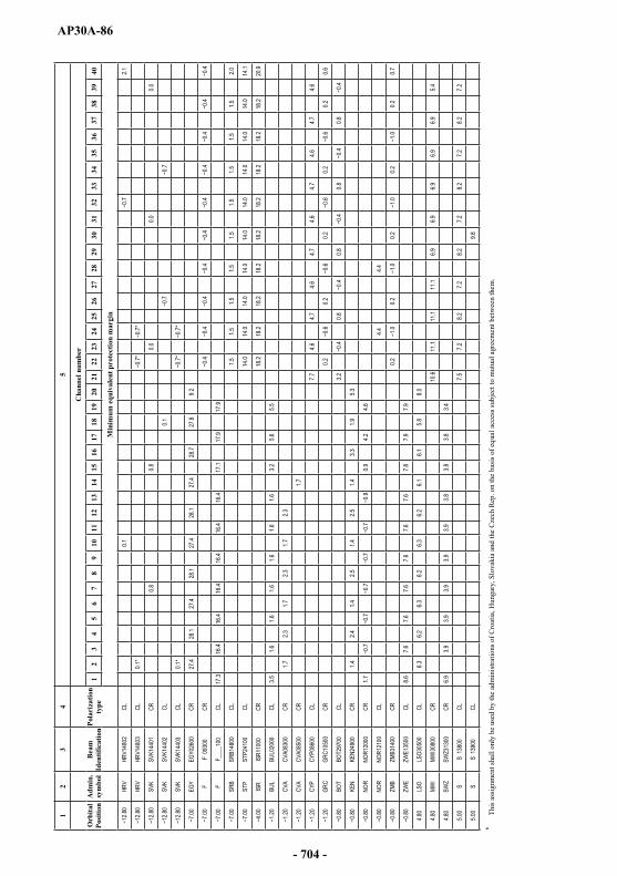
AP30A-86
12
34
5
Orb
ital
Posi
tion
Adm
in.
sym
bol
Bea
m
Iden
tific
atio
nPo
lari
zatio
n ty
pe
Cha
nnel
num
ber
12
34
56
78
910
1112
1314
1516
1718
1920
2122
2324
2526
2728
2930
3132
3334
3536
3738
3940
Min
imum
equ
ival
ent p
rote
ctio
n m
argi
n
HRV
HRV1
4802
CL0.1
2.1
0HR
VHR
V148
03CL
0.1*
SVK
SVK1
4401
CR0.8
0.80.0
0.00.0
SVK
SVK1
4402
CL0.1
SVK
SVK1
4403
CL0.1
*
EGY
EGY0
2600
CR27
.428
.127
.428
.127
.428
.127
.428
.727
.89.2
F
F 09
300
CR
.00F
F_
___1
00CL
17.3
16.4
16.4
16.4
16.4
16.4
16.4
17.1
17.9
17.9
SRB
SRB1
4800
CL1.5
1.51.5
1.51.5
1.51.5
1.51.5
2.0
STP
STP2
4100
CL14
.014
.014
.014
.014
.014
.014
.014
.014
.014
.1
ISR
ISR1
1000
CR18
.218
.218
.218
.218
.218
.218
.218
.218
.220
.9
BUL
BUL0
2000
CL3.5
1.61.6
1.61.6
1.61.6
3.25.6
5.5
CVA
CVA0
8300
CR1.7
2.31.7
2.31.7
2.3
CVA
CVA0
8500
CR1.7
CYP
CYP0
8600
CL7.7
4.64.7
4.64.7
4.64.7
4.64.7
4.6
GRC
GRC1
0500
CR0.2
0.20.2
0.20.2
0.6
BOT
BOT2
9700
CL3.2
0.80.8
0.80.8
KEN
KEN2
4900
CR1.4
2.41.4
2.51.4
2.51.4
3.31.9
5.3
80NO
RNO
R120
00CR
1.70.9
4.24.6
NOR
NOR1
2100
CL4.4
4.4
ZMB
ZMB3
1400
CR0.2
0.20.2
0.20.2
0.7
ZWE
ZWE1
3500
CL8.6
7.67.6
7.67.6
7.67.6
7.87.9
7.9
4.80
LSO
LSO3
0500
CL6.3
6.26.3
6.26.3
6.26.1
6.15.8
8.0
4.80
MWI
MWI30
800
CR10
.611
.111
.111
.16.9
6.96.9
6.96.9
5.4
4.80
SWZ
SWZ3
1300
CR6.9
3.93.9
3.93.9
3.93.8
3.83.8
3.4
5.00
SS
1380
0CL
7.57.2
8.27.2
8.27.2
8.27.2
8.27.2
5.00
SS
1390
0CL
9.8
*Th
is as
sign
men
t sha
ll on
ly b
e us
ed b
y th
e ad
min
istra
tions
of C
roat
ia, H
unga
ry, S
lova
kia
and
the
Cze
ch R
ep. o
n th
e ba
sis o
f equ
al a
cces
s sub
ject
to m
utua
l agr
eem
ent b
etw
een
them
.
- 704 -
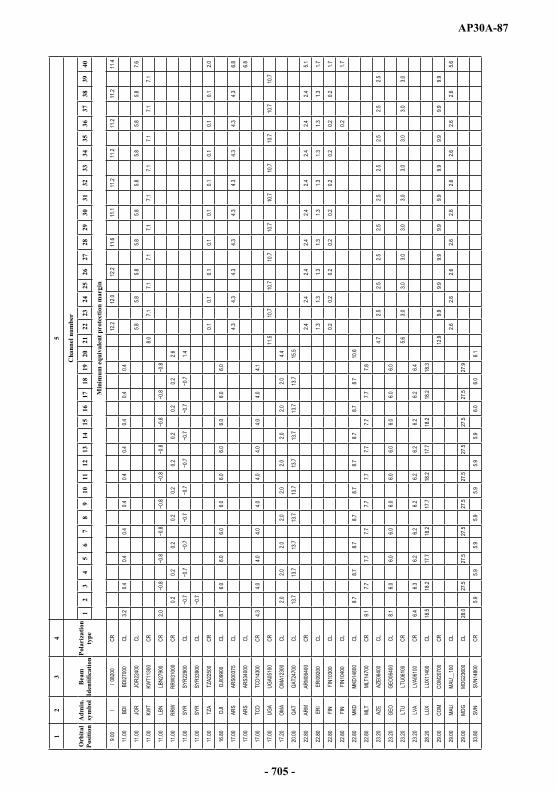
AP30A-87
12
34
5
Orb
ital
Posi
tion
Adm
in.
sym
bol
Bea
m
Iden
tific
atio
nPo
lari
zatio
n ty
pe
Cha
nnel
num
ber
12
34
56
78
910
1112
1314
1516
1718
1920
2122
2324
2526
2728
2930
3132
3334
3536
3738
3940
Min
imum
equ
ival
ent p
rote
ctio
n m
argi
n
9.00
II 0
8200
CR12
.212
.012
.211
.611
.111
.211
.211
.211
.211
.4
11.00
BDI
BDI27
000
CL3.2
0.40.4
0.40.4
0.40.4
0.40.4
0.4
11.00
JOR
JOR2
2400
CL5.8
5.85.8
5.85.8
5.85.8
5.85.8
7.6
11.00
KWT
KWT1
1300
CR8.0
7.17.1
7.17.1
7.17.1
7.17.1
7.1
11.00
LBN
LBN2
7900
CR2.0
11.00
RRW
RRW
3100
0CR
0.20.2
0.20.2
0.20.2
0.20.2
0.22.6
11.00
SYR
SYR2
2900
CL1.4
11.00
SYR
SYR3
3900
CL
11.00
TZA
TZA2
2500
CR0.1
0.10.1
0.10.1
0.10.1
0.10.1
2.0
16.80
DJI
DJI09
900
CL8.7
6.06.0
6.06.0
6.06.0
6.06.0
6.0
17.00
ARS
ARS0
0375
CL4.3
4.34.3
4.34.3
4.34.3
4.34.3
6.8
17.00
ARS
ARS3
4000
CL6.8
17.00
TCD
TCD1
4300
CR4.3
4.04.0
4.04.0
4.04.0
4.04.0
4.1
17.00
UGA
UGA0
5100
CR11
.510
.710
.710
.710
.710
.710
.710
.710
.710
.7
17.20
OMA
OMA1
2300
CL2.0
2.02.0
2.02.0
2.02.0
2.02.0
4.4
20.00
QAT
QAT2
4700
CL13
.713
.713
.713
.713
.713
.713
.713
.713
.715
.5
22.80
ARM
ARM0
6400
CR2.4
2.42.4
2.42.4
2.42.4
2.42.4
5.1
22.80
ERI
ERI09
200
CL1.3
1.31.3
1.31.3
1.31.3
1.31.3
1.7
22.80
FIN
FIN1
0300
CL0.2
0.20.2
0.20.2
0.20.2
0.20.2
1.7
22.80
FIN
FIN1
0400
CL0.2
1.7
22.80
MKD
MKD1
4800
CL8.7
8.78.7
8.78.7
8.78.7
8.78.7
10.6
22.80
MLT
MLT1
4700
CR9.1
7.77.7
7.77.7
7.77.7
7.77.7
7.8
23.20
AZE
AZE0
6400
CL4.7
2.52.5
2.52.5
2.52.5
2.52.5
2.5
23.20
GEO
GEO0
6400
CL8.1
6.06.0
6.06.0
6.06.0
6.06.0
6.0
23.20
LTU
LTU0
6100
CR5.6
3.03.0
3.03.0
3.03.0
3.03.0
3.0
23.20
LVA
LVA0
6100
CR6.4
6.36.2
6.26.2
6.26.2
6.26.2
6.4
28.20
LUX
LUX1
1400
CL18
.518
.217
.718
.217
.718
.217
.718
.218
.218
.3
29.00
COM
COM2
0700
CR12
.99.9
9.99.9
9.99.9
9.99.9
9.99.9
29.00
MAU
MAU_
_100
CL2.6
2.62.6
2.62.6
2.62.6
2.62.6
5.6
29.00
MDG
MDG2
3600
CL28
.027
.527
.527
.527
.527
.527
.527
.527
.527
.9
33.80
SVN
SVN1
4800
CR5.9
5.95.9
5.95.9
5.95.9
6.06.0
6.1
- 705 -
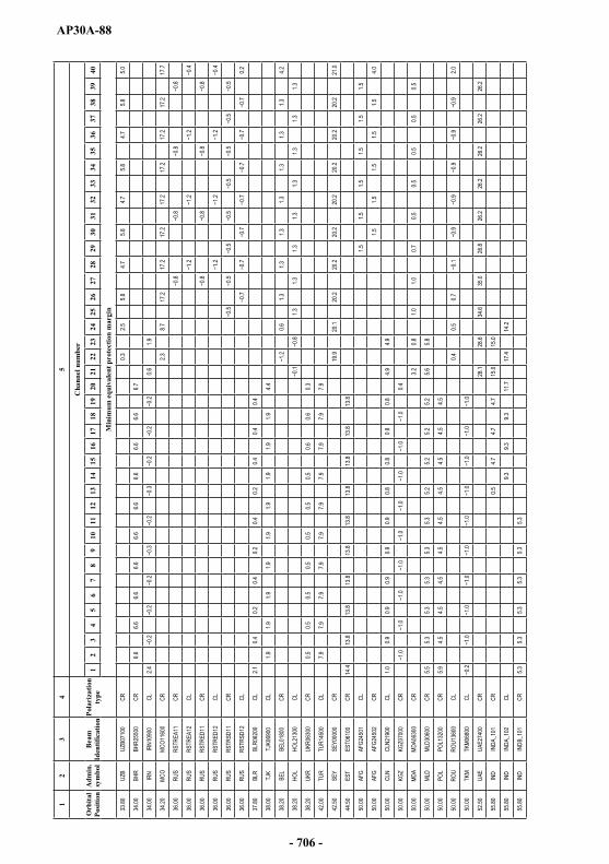
AP30A-88
12
34
5
Orb
ital
Posi
tion
Adm
in.
sym
bol
Bea
m
Iden
tific
atio
nPo
lari
zatio
n ty
pe
Cha
nnel
num
ber
12
34
56
78
910
1112
1314
1516
1718
1920
2122
2324
2526
2728
2930
3132
3334
3536
3738
3940
Min
imum
equ
ival
ent p
rote
ctio
n m
argi
n
33.80
UZB
UZB0
7100
CR0.3
2.55.8
4.75.8
4.75.8
4.75.8
5.0
34.00
BHR
BHR2
5500
CR6.6
6.66.6
6.66.6
6.66.6
6.66.6
6.7
34.00
IRN
IRN1
0900
CL2.4
0.61.9
34.20
MCO
MCO1
1600
CR2.3
8.717
.217
.217
.217
.217
.217
.217
.217
.7
36.00
RUS
RSTR
EA11
CR
36.00
RUS
RSTR
EA12
CL
36.00
RUS
RSTR
ED11
CR
36.00
RUS
RSTR
ED12
CL
36.00
RUS
RSTR
SD11
CR
36.00
RUS
RSTR
SD12
CL.7
0.2
37.80
BLR
BLR0
6200
CL2.1
0.40.2
0.40.2
0.40.2
0.40.4
0.4
38.00
TJK
TJK0
6900
CL1.9
1.91.9
1.91.9
1.91.9
1.91.9
4.4
38.20
BEL
BEL0
1800
CR0.6
1.31.3
1.31.3
1.31.3
1.34.2
38.20
HOL
HOL2
1300
CL1.3
1.31.3
1.31.3
1.31.3
1.3
38.20
UKR
UKR0
6300
CR0.5
0.50.5
0.50.5
0.50.5
0.60.6
0.3
42.00
TUR
TUR1
4500
CL7.9
7.97.9
7.97.9
7.97.9
7.97.9
7.9
42.50
SEY
SEY0
0000
CR19
.920
.120
.220
.220
.220
.220
.220
.220
.221
.0
44.50
EST
EST0
6100
CR14
.413
.813
.813
.813
.813
.813
.813
.813
.813
.8
50.00
AFG
AFG2
4501
CL1.5
1.51.5
1.51.5
1.5
50.00
AFG
AFG2
4502
CR1.5
1.51.5
1.51.5
4.0
50.00
CLN
CLN2
1900
CL1.0
0.90.9
0.90.9
0.90.8
0.80.8
0.84.9
4.9
50.00
KGZ
KGZ0
7000
CR0.4
50.00
MDA
MDA0
6300
CR3.2
0.81.0
1.00.7
0.50.5
0.50.5
0.5
50.00
MLD
MLD3
0600
CR5.5
5.35.3
5.35.3
5.35.2
5.25.2
5.25.6
5.8
50.00
POL
POL1
3200
CR5.9
4.54.5
4.54.5
4.54.5
4.54.5
4.5
50.00
ROU
ROU1
3600
CL0.4
0.50.7
2.0
50.00
TKM
TKM0
6800
CL
52.50
UAE
UAE2
7400
CR28
.128
.634
.635
.026
.826
.226
.226
.226
.226
.2
55.80
IND
INDA
_101
CR0.5
4.74.7
4.715
.015
.0
55.80
IND
INDA
_102
CL9.3
9.39.3
11.7
17.4
14.2
55.80
IND
INDB
_101
CR5.3
5.35.3
5.35.3
5.3
- 706 -
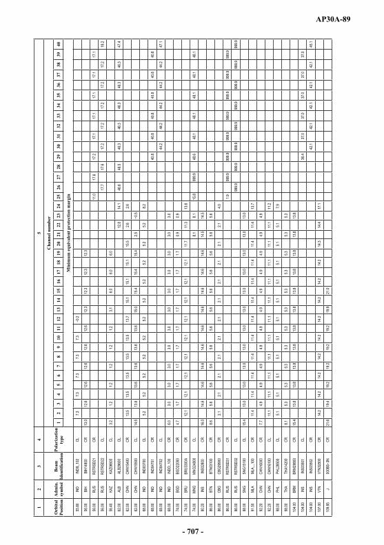
AP30A-89
12
34
5
Orb
ital
Posi
tion
Adm
in.
sym
bol
Bea
m
Iden
tific
atio
nPo
lari
zatio
n ty
pe
Cha
nnel
num
ber
12
34
56
78
910
1112
1314
1516
1718
1920
2122
2324
2526
2728
2930
3132
3334
3536
3738
3940
Min
imum
equ
ival
ent p
rote
ctio
n m
argi
n
55.80
IND
INDB
_102
CL7.3
7.37.3
7.37.3
56.00
BIH
BIH1
4800
CR13
.012
.612
.612
.612
.612
.612
.312
.312
.312
.3
56.00
RUS
RSTR
SD21
CR11
.017
.617
.217
.117
.117
.117
.117
.1
56.00
RUS
RSTR
SD22
CL17
.717
.617
.217
.217
.217
.217
.218
.2
56.40
KAZ
KAZ0
6600
CL3.2
1.21.2
1.21.2
1.23.1
6.06.0
6.0
62.00
ALB
ALB2
9600
CL12
.814
.146
.646
.546
.346
.346
.346
.346
.347
.4
62.00
CHN
CHN1
5400
CR13
.513
.513
.513
.513
.513
.715
.115
.115
.115
.52.6
2.6
62.00
CHN
CHN1
5500
CL14
.513
.613
.613
.613
.613
.615
.015
.415
.415
.42.5
68.00
IND
IND0
3700
CL5.2
5.25.2
5.25.2
5.25.2
5.25.2
5.25.2
8.2
68.00
IND
IND0
4701
CR40
.840
.840
.840
.840
.840
.8
68.00
IND
IND0
4702
CL44
.244
.244
.244
.244
.247
.1
68.00
IND
INDD
_100
CR6.0
3.03.0
3.03.0
3.03.0
3.03.0
3.03.0
3.0
74.00
BGD
BGD2
2000
CR4.7
1.71.7
1.71.7
1.71.7
1.71.7
1.70.9
0.9
74.00
BRU
BRU3
300A
CR12
.112
.112
.112
.112
.112
.112
.112
.112
.111
.711
.313
.6
74.00
MNG
MNG2
4800
CL8.1
8.115
.899
9.948
.648
.148
.148
.148
.148
.1
80.20
INS
INS0
2800
CR16
.014
.614
.614
.614
.614
.614
.614
.614
.614
.614
.514
.5
86.00
BTN
BTN0
3100
CR8.6
5.65.6
5.65.6
5.65.6
5.65.6
5.65.6
5.6
86.00
CBG
CBG2
9900
CR2.1
2.12.1
2.12.1
2.12.1
2.12.1
2.12.1
4.0
86.00
RUS
RSTR
SD31
CR1.9
999.9
999.9
999.9
999.9
999.9
999.9
999.9
86.00
RUS
RSTR
SD32
CL99
9.999
9.999
9.999
9.999
9.999
9.999
9.999
9.9
88.00
SNG
SNG1
5100
CL15
.413
.013
.013
.013
.013
.013
.013
.013
.013
.013
.013
.0
91.50
MLA
MLA_
_100
CR11
.411
.411
.411
.411
.411
.411
.411
.411
.411
.411
.413
.7
92.20
CHN
CHN1
6000
CR7.7
4.94.9
4.94.9
4.94.9
4.94.9
4.94.9
4.9
92.20
CHN
CHN1
6100
CL11
.111
.111
.111
.111
.111
.111
.111
.111
.111
.111
.111
.2
98.00
PHL
PHL2
8500
CL5.1
5.15.1
5.15.1
5.15.1
5.15.1
5.15.1
7.9
98.00
THA
THA1
4200
CR8.1
5.35.3
5.35.3
5.35.3
5.35.3
5.35.3
5.3
104.0
0BR
MBR
M298
00CR
15.4
13.8
13.8
13.8
13.8
13.8
13.8
13.8
13.8
13.8
13.8
13.8
104.0
0IN
SIN
S035
01CL
36.4
37.0
37.0
37.0
37.0
37.0
104.0
0IN
SIN
S035
02CR
42.1
42.1
42.1
42.1
42.1
45.1
107.0
0VT
NVT
N325
00CR
14.2
14.2
14.2
14.2
14.2
14.2
14.2
14.2
14.2
14.3
14.4
17.1
109.8
5J
CR21
.619
.419
.219
.219
.219
.219
.921
.0
- 707 -

AP30A-90
12
34
5
Orb
ital
Posi
tion
Adm
in.
sym
bol
Bea
m
Iden
tific
atio
nPo
lari
zatio
n ty
pe
Cha
nnel
num
ber
12
34
56
78
910
1112
1314
1516
1718
1920
2122
2324
2526
2728
2930
3132
3334
3536
3738
3940
Min
imum
equ
ival
ent p
rote
ctio
n m
argi
n
109.8
5J
J 10
985
CR23
.921
.621
.421
.421
.421
.422
.123
.121
.721
.421
.421
.4
110.0
0J
J 11
100
CR23
.721
.421
.221
.221
.221
.222
.023
.021
.621
.221
.321
.3
110.0
0J
J 11
10E
CR21
.419
.219
.019
.019
.019
.019
.820
.8
110.0
0RU
SRU
S004
01CR
29.2
999.9
14.1
13.2
13.2
13.2
13.2
13.2
110.0
0RU
SRU
S004
02CL
999.9
20.8
116.0
0KO
RKO
R112
01CL
28.2
29.2
29.2
29.2
29.2
29.2
116.0
0KO
RKO
R112
02CR
31.8
31.8
31.8
31.8
31.8
34.7
121.8
0US
AMR
A332
00CR
3.20.2
0.20.2
0.20.2
0.20.2
0.20.2
0.20.2
122.0
0CH
NCH
N200
00CL
13.8
13.8
13.8
13.8
13.8
13.8
13.9
13.9
13.8
13.8
13.8
15.9
122.0
0US
AGU
M331
01CR
29.3
28.6
28.6
28.6
28.6
28.6
122.0
0US
AGU
M331
02CL
28.6
28.6
28.6
28.6
28.6
29.3
122.2
0LA
OLA
O284
00CR
0.30.3
0.30.3
0.30.3
0.30.3
0.30.4
0.41.6
128.0
0SL
MSL
M000
00CL
16.4
13.4
13.4
13.4
13.4
13.4
13.4
13.4
13.4
13.4
13.4
13.4
128.0
0TL
STL
S000
00CR
19.6
19.6
19.6
19.6
19.6
19.6
19.6
19.6
19.6
19.6
19.6
22.6
134.0
0CH
NCH
N158
00CL
0.60.6
0.60.6
0.60.6
0.60.6
0.60.6
0.63.6
134.0
0CH
NCH
N159
00CR
2.02.0
2.02.0
2.02.0
2.02.0
2.02.0
2.02.0
134.0
0NR
UNR
U309
00CL
18.8
17.6
17.6
17.6
17.6
17.6
17.6
17.6
17.6
17.6
17.6
17.6
140.0
0F
F_
___2
00CL
10.2
10.2
10.2
10.2
10.2
10.2
10.2
10.2
10.2
10.2
10.2
11.2
140.0
0F
F_
___3
00CR
8.56.7
6.76.7
6.76.7
6.76.7
6.76.7
6.76.7
140.0
0KR
EKR
E286
00CL
13.6
12.2
12.2
12.2
12.2
12.2
12.2
12.2
12.2
12.2
12.2
12.2
140.0
0PL
WPL
W00
000
CR9.7
9.79.7
9.79.7
9.79.7
9.79.7
9.79.7
7.9
140.0
0RU
SRS
TRSD
51CR
0.199
9.93.0
1.61.6
1.61.6
1.6
140.0
0RU
SRS
TRSD
52CL
999.9
7.31.6
1.61.6
1.61.6
3.0
140.0
0VU
TVU
T128
01CL
8.98.9
8.98.9
8.98.9
140.0
0VU
TVU
T128
02CR
8.98.9
8.98.9
8.910
.4
146.0
0MH
LMH
L000
00CR
41.3
40.8
41.3
40.8
41.3
41.1
41.6
41.1
41.6
41.1
41.6
41.8
152.0
0AU
SAU
S004
00CL
152.0
0AU
SAU
S004
01CL
6.06.0
6.06.0
6.06.0
152.0
0AU
SAU
S004
02CL
6.06.0
6.06.0
6.06.0
152.0
0AU
SAU
S004
03CL
6.06.0
6.06.0
6.06.0
152.0
0AU
SAU
S004
04CL
6.06.0
6.06.0
6.06.0
- 708 -

AP30A-91
12
34
5
Orb
ital
Posi
tion
Adm
in.
sym
bol
Bea
m
Iden
tific
atio
nPo
lari
zatio
n ty
pe
Cha
nnel
num
ber
12
34
56
78
910
1112
1314
1516
1718
1920
2122
2324
2526
2728
2930
3132
3334
3536
3738
3940
Min
imum
equ
ival
ent p
rote
ctio
n m
argi
n
152.0
0AU
SAU
S004
05CL
6.06.0
6.06.0
6.06.0
152.0
0AU
SAU
S004
06CL
6.06.0
6.06.0
6.06.0
152.0
0AU
SAU
S004
0ACL
152.0
0AU
SAU
S005
00CR
152.0
0AU
SAU
S005
01CR
3.03.0
6.06.0
6.06.0
152.0
0AU
SAU
S005
02CR
3.03.0
6.06.0
6.06.0
152.0
0AU
SAU
S005
03CR
3.03.0
6.06.0
6.06.0
152.0
0AU
SAU
S005
04CR
3.03.0
6.06.0
6.06.0
152.0
0AU
SAU
S005
05CR
3.03.0
6.06.0
6.06.0
152.0
0AU
SAU
S005
06CR
3.03.0
6.06.0
6.06.0
152.0
0AU
SAU
S006
00CR
999.9
999.9
999.9
999.9
999.9
999.9
152.0
0AU
SAU
S006
01CR
999.9
999.9
999.9
999.9
999.9
999.9
152.0
0AU
SAU
S006
02CR
999.9
999.9
999.9
999.9
999.9
999.9
152.0
0AU
SAU
S006
03CR
999.9
999.9
999.9
999.9
999.9
999.9
152.0
0AU
SAU
S006
04CR
999.9
999.9
999.9
999.9
999.9
999.9
152.0
0AU
SAU
S006
05CR
999.9
999.9
999.9
999.9
999.9
999.9
152.0
0AU
SAU
S006
06CR
999.9
999.9
999.9
999.9
999.9
999.9
152.0
0AU
SAU
SA00
00CL
39.7
152.0
0AU
SAU
SA00
01CL
61.2
6.06.0
152.0
0AU
SAU
SA00
02CL
60.5
6.06.0
152.0
0AU
SAU
SA00
03CL
61.5
6.06.0
152.0
0AU
SAU
SA00
04CL
53.4
6.06.0
152.0
0AU
SAU
SA00
05CL
55.9
6.06.0
152.0
0AU
SAU
SA00
06CL
48.3
6.06.0
158.0
0FS
MFS
M000
00CR
8.85.7
5.75.7
5.75.7
5.75.7
5.75.7
5.75.7
158.0
0NZ
LNZ
L__1
00CL
8.58.4
8.58.4
8.58.4
8.68.6
8.68.6
8.611
.2
164.0
0AU
SAU
S007
00CR
0.10.1
0.1
164.0
0AU
SAU
S007
01CR
3.03.0
3.06.0
6.06.0
164.0
0AU
SAU
S007
02CR
3.03.0
3.06.0
6.06.0
164.0
0AU
SAU
S007
03CR
3.03.0
3.06.0
6.06.0
164.0
0AU
SAU
S007
04CR
3.03.0
3.06.0
6.06.0
- 709 -
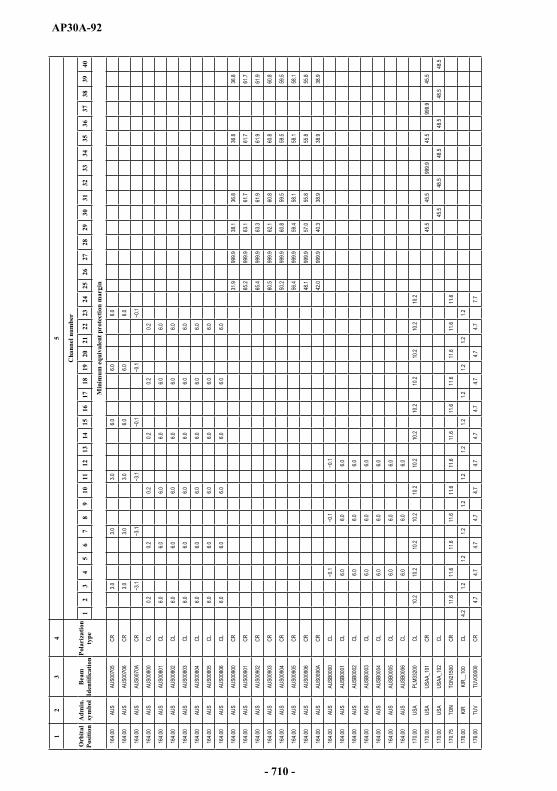
AP30A-92
12
34
5
Orb
ital
Posi
tion
Adm
in.
sym
bol
Bea
m
Iden
tific
atio
nPo
lari
zatio
n ty
pe
Cha
nnel
num
ber
12
34
56
78
910
1112
1314
1516
1718
1920
2122
2324
2526
2728
2930
3132
3334
3536
3738
3940
Min
imum
equ
ival
ent p
rote
ctio
n m
argi
n
164.0
0AU
SAU
S007
05CR
3.03.0
3.06.0
6.06.0
164.0
0AU
SAU
S007
06CR
3.03.0
3.06.0
6.06.0
164.0
0AU
SAU
S007
0ACR
164.0
0AU
SAU
S008
00CL
0.20.2
0.20.2
0.20.2
164.0
0AU
SAU
S008
01CL
6.06.0
6.06.0
6.06.0
164.0
0AU
SAU
S008
02CL
6.06.0
6.06.0
6.06.0
164.0
0AU
SAU
S008
03CL
6.06.0
6.06.0
6.06.0
164.0
0AU
SAU
S008
04CL
6.06.0
6.06.0
6.06.0
164.0
0AU
SAU
S008
05CL
6.06.0
6.06.0
6.06.0
164.0
0AU
SAU
S008
06CL
6.06.0
6.06.0
6.06.0
164.0
0AU
SAU
S009
00CR
31.9
999.9
38.1
36.8
36.8
36.8
164.0
0AU
SAU
S009
01CR
65.2
999.9
63.1
61.7
61.7
61.7
164.0
0AU
SAU
S009
02CR
65.4
999.9
63.3
61.9
61.9
61.9
164.0
0AU
SAU
S009
03CR
60.5
999.9
62.1
60.8
60.8
60.8
164.0
0AU
SAU
S009
04CR
50.2
999.9
60.8
59.5
59.5
59.5
164.0
0AU
SAU
S009
05CR
56.4
999.9
59.4
58.1
58.1
58.1
164.0
0AU
SAU
S009
06CR
48.1
999.9
57.0
55.8
55.8
55.8
164.0
0AU
SAU
S009
0ACR
42.0
999.9
40.3
38.9
38.9
38.9
164.0
0AU
SAU
SB00
00CL
164.0
0AU
SAU
SB00
01CL
6.06.0
6.0
164.0
0AU
SAU
SB00
02CL
6.06.0
6.0
164.0
0AU
SAU
SB00
03CL
6.06.0
6.0
164.0
0AU
SAU
SB00
04CL
6.06.0
6.0
164.0
0AU
SAU
SB00
05CL
6.06.0
6.0
164.0
0AU
SAU
SB00
06CL
6.06.0
6.0
170.0
0US
APL
M332
00CL
10.2
10.2
10.2
10.2
10.2
10.2
10.2
10.2
10.2
10.2
10.2
10.2
170.0
0US
AUS
AA_1
01CR
45.5
45.5
999.9
45.5
999.9
45.5
170.0
0US
AUS
AA_1
02CL
45.5
48.5
48.5
48.5
48.5
48.5
170.7
5TO
NTO
N215
00CR
11.6
11.6
11.6
11.6
11.6
11.6
11.6
11.6
11.6
11.6
11.6
11.6
176.0
0KI
RKI
R__1
00CL
4.21.2
1.21.2
1.21.2
1.21.2
1.21.2
1.21.2
176.0
0TU
VTU
V000
00CR
4.74.7
4.74.7
4.74.7
4.74.7
4.74.7
4.77.7
- 710 -
AP30A-93
ARTICLE 10
Interference
10.1 The Member States shall endeavour to agree on the action required to reduce harmful interference which might be caused by the application of these provisions and the associated Plans.
ARTICLE 11
Period of validity of the provisions and associated Plans
11.1 The provisions and associated Plans have been prepared in order to meet the requirements for feeder-links for the broadcasting-satellite service in the bands concerned for a period extending until at least 1 January 1994.
11.2 In any event, the provisions and associated Plans shall remain in force until their revision by a competent administrative radio conference convened in accordance with the relevant provisions of the Convention in force.
ANNEX 1
Limits for determining whether a service of an administration is considered to be affected by a proposed modification to the Region 2 feeder-link Plan
or by a proposed new or modified assignment in the Regions 1 and 3 feeder-link List or when it is necessary under this Appendix to seek
the agreement of any other administration (Rev.WRC-03)
1 (SUP - WRC-2000)
2 (SUP - WRC-2000)
3 Limits to the change in the overall equivalent protection margin with respect to frequency assignments in conformity with the Region 2feeder-link Plan33 (WRC-2000)
With respect to the modification to the Region 2 feeder-link Plan and when it is necessary under this Appendix to seek the agreement of any other administration of Region 2, except in cases covered by Resolution 42 (Rev.WRC-03)*, an administration is considered as being affected if the overall
_______________33 With respect to § 3 the limit specified relates to the overall equivalent protection margin calculated in accordance with § 1.12 of Annex 3.
* Note by the Secretariat: This Resolution was revised by WRC-12 and WRC-15.
- 711 -
AP30A-94
equivalent protection margin34 corresponding to a test point of its entry in that Plan, including the cumulative effect of any previous modification to that Plan or any previous agreement, falls more than 0.25 dB below 0 dB, or, if already negative, more than 0.25 dB below the value resulting from:
the feeder-link Plan as established by the 1983 Conference; or
a modification of the assignment in accordance with this Appendix; or
a new entry in the feeder-link Plan under Article 4; or
any agreement reached in accordance with this Appendix except for Resolution 42 (Rev.WRC-03)*. (WRC-03)
4 Limits to the interference into frequency assignments in conformity with the Regions 1 and 3 feeder-link Plan or with the Regions 1 and 3 feeder-link List or proposed new or modified assignments in the Regions 1and 3 feeder-link List (WRC-03)
Under assumed free-space propagation conditions, the power flux-density of a proposed new or modified assignment in the feeder-link List shall not exceed the value of 76 dB(W/(m2 · 27 MHz))at any point in the geostationary-satellite orbit, and the relative off-axis e.i.r.p. of the associated feeder-link antenna shall be in compliance with Fig. A (WRC-97 curves) of Annex 3. (WRC-03)
With respect to § 4.1.1 a) or b) of Article 4, an administration in Region 1 or 3 is considered by the Bureau as being affected if the minimum orbital spacing between the wanted and interfering space stations, under worst-case station-keeping conditions, is less than 9°. (WRC-03)
However, an administration is not considered as being affected if, under assumed free-space propagation conditions, the effect of the proposed new or modified assignments in the feeder-link List is that the feeder-link equivalent protection margin35 corresponding to a test point of its assignment in the feeder-link Plan or the feeder-link List or for which the procedure of Article 4 has been initiated, including the cumulative effect of any previous modification to the feeder-link List or any previous agreement, does not fall more than 0.45 dB below 0 dB, or, if already negative, more than 0.45 dB below the value resulting from:
the Regions 1 and 3 feeder-link Plan and List as established by WRC-2000; or
a proposed new or modified assignment to the feeder-link List in accordance with this Appendix; or
a new entry in the Regions 1 and 3 feeder-link List as a result of the successful application of Article 4 procedures. (WRC-03)
_______________34 For the definition of the overall equivalent protection margin, see § 1.11 of Annex 5 to Appendix 30.
* Note by the Secretariat: This Resolution was revised by WRC-12 and WRC-15.
35 For the definition of the equivalent protection margin, see § 1.7 of Annex 3.
- 712 -
AP30A-95
For a proposed new or modified assignment to the feeder-link List, in the interference analysis, for each test point, the antenna characteristics described in § 3.5 of Annex 3 shall apply. (WRC-03)
5 Limits applicable to protect a frequency assignment in the bands 17.3-18.1 GHz (Regions 1 and 3) and 17.3-17.8 GHz (Region 2) to a receiving space station in the fixed-satellite service (Earth-to-space)
An administration in Region 1 or 3 is considered as being affected by a proposed modification in Region 2, with respect to § 4.2.2 a) or 4.2.2 b) of Article 4, or an administration in Region 2 is considered as being affected by a proposed new or modified assignment in the Regions 1 and 3 feeder-link List, with respect to § 4.1.1 c) of Article 4, when the power flux-density arriving at the receiving space station of a broadcasting-satellite feeder-link would cause an increase in the noise temperature of the feeder-link space station which exceeds the threshold value of T /T corresponding to 6%, where T / T is calculated in accordance with the method given in Appendix 8, except that the maximum power densities per hertz averaged over the worst 1 MHz are replaced by power densities per hertz averaged over the necessary bandwidth of the feeder-link carriers. (WRC-03)
Interim systems of Region 2 in accordance with Resolution 42 (Rev.WRC-03)* shall not be taken into consideration when applying the above paragraph to proposed new or modified assignments in the Regions 1 and 3 feeder-link List. However, the above paragraph shall be applied to Region 2interim systems with respect to Regions 1 and 3 administrations, referred to in § 5.2 b) of Resolution 42 (Rev.WRC-03)*. (WRC-03)
6 Limits applicable to protect a frequency assignment in the band 17.8-18.1 GHz (Region 2) to a receiving feeder-link space station in the fixed-satellite service (Earth-to-space) or a frequency assignment in the frequency bands 14.5-14.75 GHz (in countries listed in Resolution 163 (WRC-15)) and 14.5-14.8 GHz (in countries listed in Resolution 164 (WRC-15)) to a receiving space station in the fixed-satellite service (Earth-to-space) not subject to a Plan (WRC-15)
With respect to § 4.1.1 d) of Article 4, an administration is considered affected by a proposed new or modified assignment in the Regions 1 and 3 feeder-link List when the power flux-density arriving at the receiving space station of a broadcasting-satellite feeder link in Region 2 or the receiving space station of the fixed-satellite service uplinks not subject to a Plan in all Regions of that administration would cause an increase in the noise temperature of the receiving uplink space station which exceeds
T/T T/T is calculated in accordance with the method given in Appendix 8, except that the maximum power densities per hertz averaged over the worst 1 MHz are replaced by power densities per hertz averaged over the necessary bandwidth of the feeder-link carriers. (WRC-15)
_______________* Note by the Secretariat: This Resolution was revised by WRC-12 and WRC-15.
- 713 -
AP30A-96
ANNEX 2 (REV.WRC-03)
Basic characteristics to be furnished in notices relating to feeder-link stations in the fixed-satellite service operating in the frequency
bands 14.5-14.8 GHz and 17.3-18.1 GHz
These data are listed in Appendix 4.
ANNEX 3
Technical data used in establishing the provisions and associated Plans and Regions 1 and 3 feeder-link List, which should
be used for their application36 (Rev.WRC-03)
1 Definitions
1.1 Feeder link
The term feeder link, as defined in No. 1.115, is further qualified to indicate a fixed-satellite service link in the frequency band 17.3-17.8 GHz in the Region 2 broadcasting-satellite service Plan and in the frequency bands 14.5-14.8 GHz for countries outside Europe, and 17.3-18.1 GHz in the Regions 1and 3 Plan, from any earth station within the feeder-link service area to the associated space station in the broadcasting-satellite service.
1.2 Feeder-link beam area
The area delineated by the intersection of the half-power beam of the satellite receiving antenna with the surface of the Earth.
1.3 Feeder-link service area
The area on the surface of the Earth within the feeder-link beam area within which the administration responsible for the service has the right to locate transmitting earth stations for the purpose of providing feeder-links to broadcasting-satellite space stations.
_______________36 In revising this Annex at WRC-97 and at WRC-2000, no changes were made to the technical data applicable to the Region 2 feeder-link Plan. However, for all three Regions it should be noted that some of the parameters of networks proposed as modifications to the Region 2 feeder-link Plan and the Regions 1 and 3 feeder-link Lists may differ from the technical data presented herein. (WRC-2000)
- 714 -
AP30A-97
1.4 Nominal orbital position
The longitude of a position in the geostationary-satellite orbit associated with a frequency assignment to a space station in a space radiocommunication service. The position is given in degrees from the Greenwich meridian.
1.5 Adjacent channel
The RF channel in the broadcasting-satellite service frequency Plan, or in the associated feeder-link frequency Plan, which is situated immediately higher or lower in frequency with respect to the reference channel.
1.6 Second adjacent channel
The RF channel in the broadcasting-satellite service frequency Plan, or in the associated feeder-link frequency Plan, which is situated immediately beyond either of the adjacent channels, with respect to the reference channel.
1.7 Feeder-link equivalent protection margin for Regions 1 and 337 (WRC-2000)
The feeder-link equivalent protection margin (Mu) is given by the formula:
101010 321 101010log10 MMMuM dB
where:
M1: is the value in dB of the protection margin for the same channel, i.e.:
ratioprotectionchannel-co
powersginterferinchannel-cotheofsum
powerwanted1M
_______________37 This quantity is used in the alternative formula for the overall equivalent protection margin given in § 1.12. However, in certain cases (e.g. when the channel spacing and/or bandwidth are different from the values given in § 3.5 and 3.8 of Annex 5 to Appendix 30) the Bureau will use the worst-case approach until a relevant ITU-R Recommendation is incorporated in this Annex by reference. (WRC-2000)
- 715 -
AP30A-98
M2 and M3: are the values in dB of the protection margin for the upper and lower adjacent channels, respectively, i.e.:
ratioprotectionchanneladjacent
powersginterferinchanneladjacentuppertheofsum
powerwanted2M
ratioprotectionchanneladjacent
powersginterferinchanneladjacentlowertheofsum
powerwanted3M
All powers are evaluated at the receiver input. All protection ratios are given in § 3.3.
1.8 Overall carrier-to-interference (C/I) ratio
The overall C/I ratio is the ratio of the wanted carrier power to the sum of all interfering RF powers in a given channel including both feeder-links and downlinks. The overall C/I ratio due to interference from the given channel is calculated as the reciprocal of the sum of the reciprocals of the feeder-link C/I ratio and the downlink C/I ratio referred to the satellite receiver input and earth station receiver input, respectively38.
1.9 Overall co-channel protection margin
The overall co-channel protection margin in a given channel is the difference (dB) between the overall co-channel C/I ratio and the co-channel protection ratio.
1.10 Overall adjacent channel protection margin
The overall adjacent channel protection margin is the difference (dB) between the overall adjacent channel C/I ratio and the adjacent channel protection ratio.
1.11 Overall second adjacent channel protection margin
The overall second adjacent channel protection margin is the difference (dB) between the overall second adjacent channel C/I ratio and the second adjacent channel protection ratio.
_______________38 In Region 2, there are a total of five overall C/I ratios used in the analysis of the Plan, namely, co-channel, upper and lower adjacent channels and upper and lower second adjacent channels. In Regions 1 and 3, three ratios are used, namely, co-channel and upper and lower adjacent channels.
- 716 -

AP30A-99
1.12 Overall equivalent protection margin
The overall equivalent protection margin M is given in dB by the expression39:
n
i
M iM1
1010log10
where:
n: is generally equal to 3 for Regions 1 and 3, n is equal to 5 for Region 2
M1: overall co-channel protection margin (dB) (as defined in § 1.9)
M2, M3: overall adjacent channel protection margins for the upper and lower adjacent channels, respectively (dB) (as defined in § 1.10)
M4, M5: overall second adjacent channel protection margins for the upper and lower second adjacent channels, respectively (dB) as defined in § 1.11).40
erference sources from the adjacent and second adjacent as well as co-channel interference sources have been included.
The following alternative formula for overall equivalent protection margin was used at the 1988 Conference (WARC Orb-88) in developing the original feeder-link Plan for Regions 1 and 3. It may be used as a tool to assess the relative contributions of the feeder link and downlink to the overall equivalent protection margin defined above.
coRMRM RM cddcuu 1010 1010log10
where:
Mu: equivalent protection margin for the feeder link (as defined in § 1.7)
Md: equivalent protection margin for the downlink (as defined in § 3.4, Annex 5 to Appendix 30
Rcu: co-channel feeder-link protection ratio
Rcd : co-channel downlink protection ratio
Rco: co-channel overall protection ratio.
The values of the protection ratios used for the 1988 feeder-link Plan were as follows:
Rcu = 40 dB
Rcd = 31 dB
Rco = 30 dB
_______________39 This formula is also used to calculate the overall equivalent protection margin of the assignments notified, which are in conformity with this Appendix, brought into use, and for which the date of bringing into use has been confirmed to the Bureau before 27 October 1997.
40 M4 and M5 are applicable only for Region 2. (WRC-2000)
- 717 -
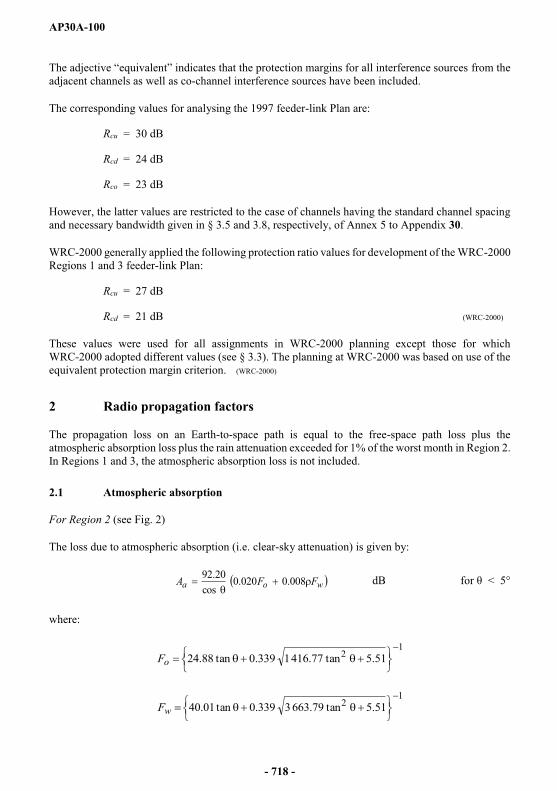
AP30A-100
from the adjacent channels as well as co-channel interference sources have been included.
The corresponding values for analysing the 1997 feeder-link Plan are:
Rcu = 30 dB
Rcd = 24 dB
Rco = 23 dB
However, the latter values are restricted to the case of channels having the standard channel spacing and necessary bandwidth given in § 3.5 and 3.8, respectively, of Annex 5 to Appendix 30.
WRC-2000 generally applied the following protection ratio values for development of the WRC-2000 Regions 1 and 3 feeder-link Plan:
Rcu = 27 dB
Rcd = 21 dB (WRC-2000)
These values were used for all assignments in WRC-2000 planning except those for which WRC-2000 adopted different values (see § 3.3). The planning at WRC-2000 was based on use of the equivalent protection margin criterion. (WRC-2000)
2 Radio propagation factors
The propagation loss on an Earth-to-space path is equal to the free-space path loss plus the atmospheric absorption loss plus the rain attenuation exceeded for 1% of the worst month in Region 2. In Regions 1 and 3, the atmospheric absorption loss is not included.
2.1 Atmospheric absorption
For Region 2 (see Fig. 2)
The loss due to atmospheric absorption (i.e. clear-sky attenuation) is given by:
woa FFA 008.0020.0cos
20.92 dB for < 5°
where:
1
2 51.5tan77.4161339.0tan88.24oF
1
2 51.5tan79.6633339.0tan01.40wF
- 718 -
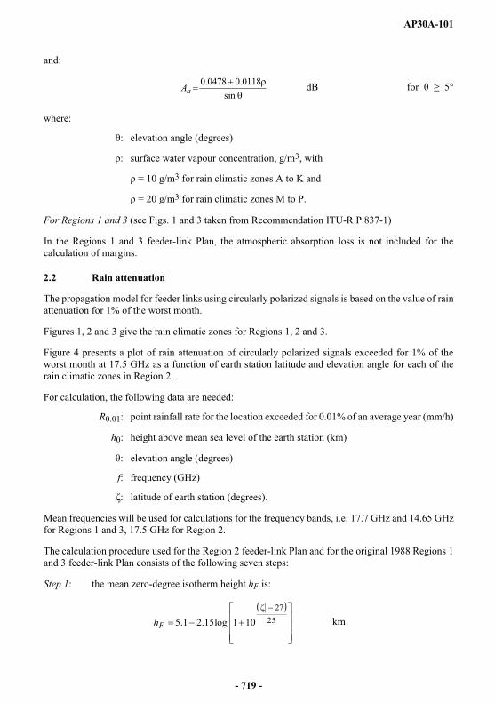
AP30A-101
and:
sin
0118.00478.0aA dB for 5°
where:
elevation angle (degrees)
surface water vapour concentration, g/m3, with
= 10 g/m3 for rain climatic zones A to K and
= 20 g/m3 for rain climatic zones M to P.
For Regions 1 and 3 (see Figs. 1 and 3 taken from Recommendation ITU-R P.837-1)
In the Regions 1 and 3 feeder-link Plan, the atmospheric absorption loss is not included for the calculation of margins.
2.2 Rain attenuation
The propagation model for feeder links using circularly polarized signals is based on the value of rain attenuation for 1% of the worst month.
Figures 1, 2 and 3 give the rain climatic zones for Regions 1, 2 and 3.
Figure 4 presents a plot of rain attenuation of circularly polarized signals exceeded for 1% of the worst month at 17.5 GHz as a function of earth station latitude and elevation angle for each of the rain climatic zones in Region 2.
For calculation, the following data are needed:
R0.01: point rainfall rate for the location exceeded for 0.01% of an average year (mm/h)
h0: height above mean sea level of the earth station (km)
elevation angle (degrees)
f: frequency (GHz)
latitude of earth station (degrees).
Mean frequencies will be used for calculations for the frequency bands, i.e. 17.7 GHz and 14.65 GHz for Regions 1 and 3, 17.5 GHz for Region 2.
The calculation procedure used for the Region 2 feeder-link Plan and for the original 1988 Regions 1and 3 feeder-link Plan consists of the following seven steps:
Step 1: the mean zero-degree isotherm height hF is:
2527
101log15.21.5Fh km
- 719 -
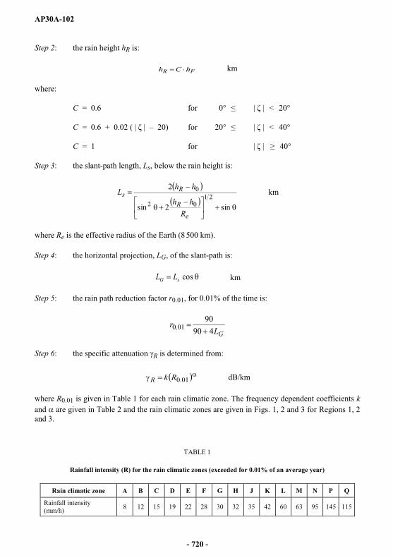
AP30A-102
Step 2: the rain height hR is:
FR hCh km
where:
C = 0.6 for 0° < 20°
C = 0.6 + 20) for 20° < 40°
C = 1 for 40°
Step 3: the slant-path length, Ls, below the rain height is:
sin2sin
221
02
0
e
R
Rs
Rhh
hhL km
where Re is the effective radius of the Earth (8 500 km).
Step 4: the horizontal projection, LG, of the slant-path is:
cossG LL km
Step 5: the rain path reduction factor r0.01, for 0.01% of the time is:
GL
r490
9001.0
Step 6: the specific attenuation R is determined from:
01.0RkR dB/km
where R0.01 is given in Table 1 for each rain climatic zone. The frequency dependent coefficients kand are given in Table 2 and the rain climatic zones are given in Figs. 1, 2 and 3 for Regions 1, 2 and 3.
TABLE 1
Rainfall intensity (R) for the rain climatic zones (exceeded for 0.01% of an average year)
Rain climatic zone A B C D E F G H J K L M N P Q
Rainfall intensity (mm/h) 8 12 15 19 22 28 30 32 35 42 60 63 95 145 115
- 720 -

AP30A-103
TABLE 2
Frequency dependent coefficients
Frequency(GHz) k
14.65 0.0327 1.149 For Regions 1 and 317.5 0.0521 1.114 For Region 217.7 0.0531 1.110 For Regions 1 and 3
Step 7: the attenuation exceeded for 1% of the worst month is:
A1% = R Ls r0.01 dB for Regions 1 and 3
A1% = R Ls r0.01 dB for Region 2.
For calculation of the permissible increase in e.i.r.p. to overcome rain fading (power control, see § 3.11.1) in the Regions 1 and 3 Plan revised by WRC-97, the same calculation procedure is used with the following changes to conform to Recommendation ITU-R P.618-5.
To calculate the rain height hR, Steps 1 and 2 are replaced by:
HemisphereSouthern71for0HemisphereSouthern2171for211.05HemisphereSouthern210for5HemisphereNorthern230for5HemisphereNorthern23for23075.05
Rh
Steps 3 and 4 remain the same. However, to calculate the rain path reduction factor r0.01, for 0.01% of the time, the equation of Step 5 is replaced by:
0
01.0 11
LLr
G
where:
L0 = R0.01)
and R0.01 is given in Table 1 for each rain climatic zone.
Step 6 remains the same except the frequency dependent coefficients k and shall be obtained from Recommendation ITU-R P.838-3. (WRC-07)
Step 7 should be replaced as follows:
)log043.0546.0(
01.012.0 pp p
AA
where:
p (%) = 0.30 pw (%)1.15 (Recommendation ITU-R P.841)
p is the average annual time percentage of excess corresponding to desired worst-month time percentage of excess pw.
- 721 -
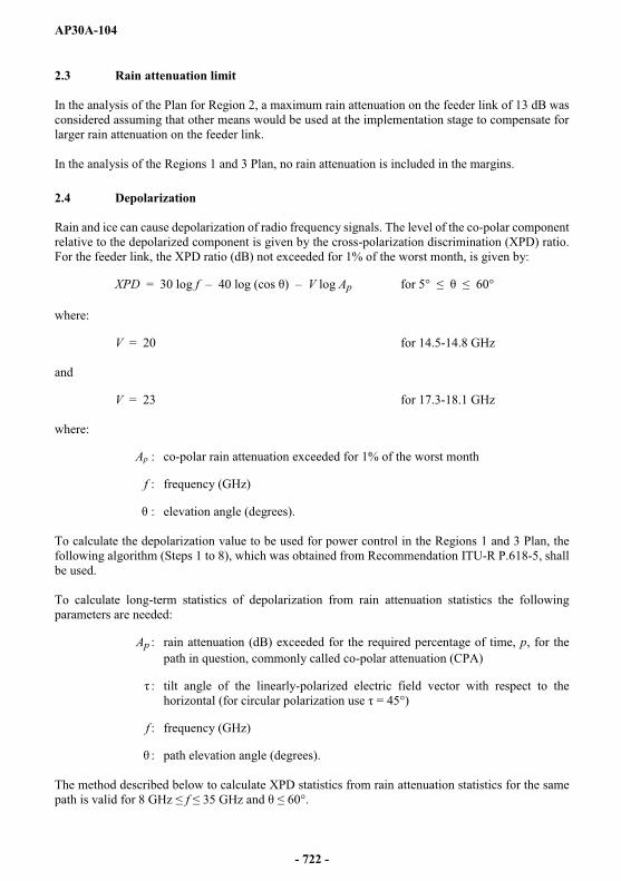
AP30A-104
2.3 Rain attenuation limit
In the analysis of the Plan for Region 2, a maximum rain attenuation on the feeder link of 13 dB was considered assuming that other means would be used at the implementation stage to compensate for larger rain attenuation on the feeder link.
In the analysis of the Regions 1 and 3 Plan, no rain attenuation is included in the margins.
2.4 Depolarization
Rain and ice can cause depolarization of radio frequency signals. The level of the co-polar component relative to the depolarized component is given by the cross-polarization discrimination (XPD) ratio. For the feeder link, the XPD ratio (dB) not exceeded for 1% of the worst month, is given by:
XPD = 30 log f 40 log (cos ) V log Ap for 5° 60°
where:
V = 20 for 14.5-14.8 GHz
and
V = 23 for 17.3-18.1 GHz
where:
Ap : co-polar rain attenuation exceeded for 1% of the worst month
f : frequency (GHz)
: elevation angle (degrees).
To calculate the depolarization value to be used for power control in the Regions 1 and 3 Plan, thefollowing algorithm (Steps 1 to 8), which was obtained from Recommendation ITU-R P.618-5, shall be used.
To calculate long-term statistics of depolarization from rain attenuation statistics the following parameters are needed:
Ap : rain attenuation (dB) exceeded for the required percentage of time, p, for the path in question, commonly called co-polar attenuation (CPA)
: tilt angle of the linearly-polarized electric field vector with respect to the horizontal (for circular polarization use = 45°)
f : frequency (GHz)
: path elevation angle (degrees).
The method described below to calculate XPD statistics from rain attenuation statistics for the same path is valid for 8 GHz f 35 60°.
- 722 -
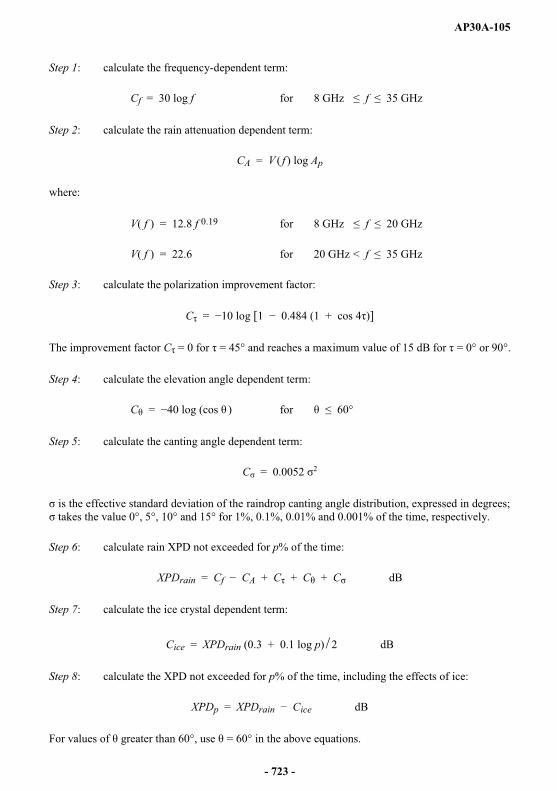
AP30A-105
Step 1: calculate the frequency-dependent term:
Cf = 30 log f for 8 GHz f 35 GHz
Step 2: calculate the rain attenuation dependent term:
CA = V ( f ) log Ap
where:
V( f ) = 12.8 f 0.19 for 8 GHz f 20 GHz
V( f ) = 22.6 for 20 GHz < f 35 GHz
Step 3: calculate the polarization improvement factor:
C = 10 log [1 0.484 (1 + cos 4 )]
The improvement factor C = 0 for = 45° and reaches a maximum value of 15 dB for = 0° or 90°.
Step 4: calculate the elevation angle dependent term:
C = 40 log (cos ) for 60°
Step 5: calculate the canting angle dependent term:
C = 0.0052 2
is the effective standard deviation of the raindrop canting angle distribution, expressed in degrees; °, 5°, 10° and 15° for 1%, 0.1%, 0.01% and 0.001% of the time, respectively.
Step 6: calculate rain XPD not exceeded for p% of the time:
XPDrain = Cf CA + C + C + C dB
Step 7: calculate the ice crystal dependent term:
Cice = XPDrain (0.3 + 0.1 log p) 2 dB
Step 8: calculate the XPD not exceeded for p% of the time, including the effects of ice:
XPDp = XPDrain Cice dB
= 60° in the above equations.
- 723 -
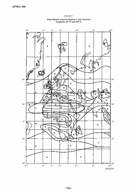
AP30A-106
AP30AA3-01
45° 15° 0° 15° 45° 75° 105°
30°
0°
30°
60°
60°45° 15° 0° 15° 45° 75° 105°
30°
0°
30°
60°
60°
FIGURE 1Rain-climatic zones for Regions 1 and 3 between
longitudes 45° W and 105° E
- 724 -

AP30A-107
AP30AA3-02
165° 135° 105° 75° 45° 15°
30°
0°
30°
60°
60°
30°
0°
30°
60°
60°165° 135° 105° 75° 45° 15°
FIGURE 2Rain-climatic zones (Region 2)
- 725 -

AP30A-108
AP30AA3-03
60° 90° 120° 150° 180° 150°
30°
0°
30°
60°
60°60° 90° 120° 150° 180° 150°
30°
0°
30°
60°
60°
FIGURE 3Rain-climatic zones for Regions 1 and 3 between
longitudes 60° E and 150° W
- 726 -
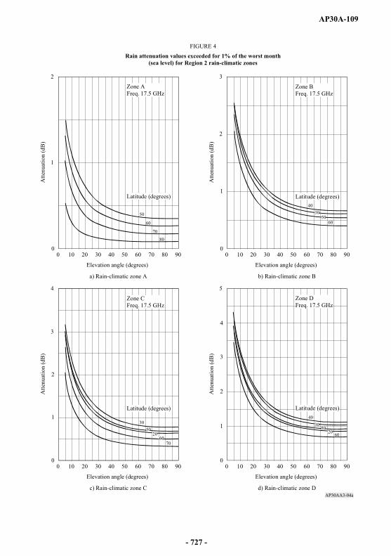
AP30A-109
AP30AA3-04a
0
2
1
80706050403020100 900
3
1
2
80706050403020100 90
0
4
2
1
3
80706050403020100 900
5
1
4
2
3
80706050403020100 90
4030
5020 60
3050
2060
70
3050
6060
70
50
80
40
FIGURE 4Rain attenuation values exceeded for 1% of the worst month
(sea level) for Region 2 rain-climatic zones
Elevation angle (degrees)
Atte
nuat
ion
(dB
)
Zone AFreq. 17.5 GHz
Latitude (degrees)
a) Rain-climatic zone A
Zone BFreq. 17.5 GHz
Latitude (degrees)
Atte
nuat
ion
(dB
)
b) Rain-climatic zone B
Elevation angle (degrees)
Elevation angle (degrees)
Atte
nuat
ion
(dB
)
Zone CFreq. 17.5 GHz
Latitude (degrees)
c) Rain-climatic zone C
Zone DFreq. 17.5 GHz
Latitude (degrees)
Atte
nuat
ion
(dB
)
d) Rain-climatic zone D
Elevation angle (degrees)
- 727 -
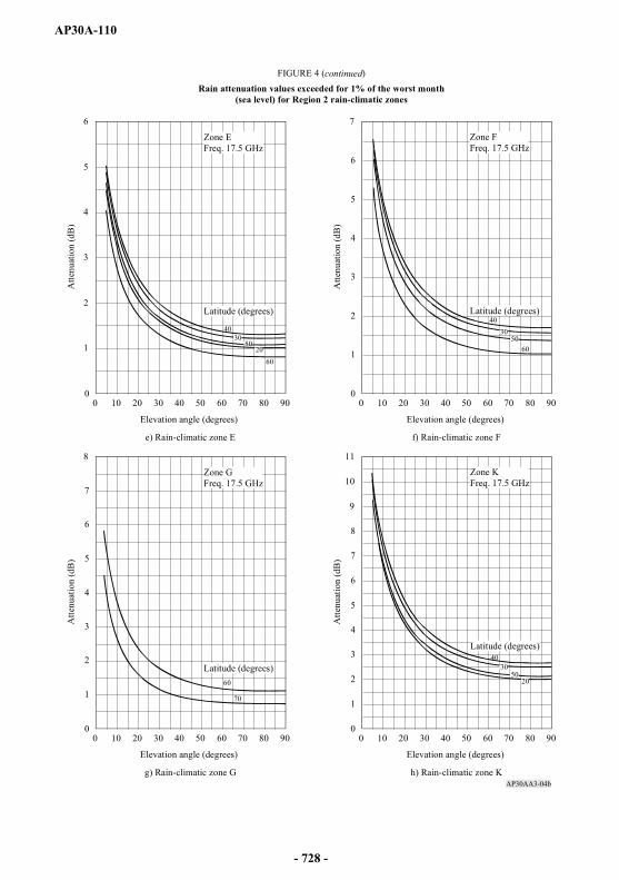
AP30A-110
AP30AA3-04b
0
6
4
2
1
3
5
80706050403020100 900
7
4
1
5
2
3
6
80706050403020100 90
0
8
2
4
6
1
3
5
7
80706050403020100 900
11
4
1
5
9
2
3
6
7
8
10
80706050403020100 90
3050
2060
70
3050
6030
40
60
50
40
20
40
FIGURE 4 (continued)Rain attenuation values exceeded for 1% of the worst month
(sea level) for Region 2 rain-climatic zones
Elevation angle (degrees)
Atte
nuat
ion
(dB
)
Zone EFreq. 17.5 GHz
Latitude (degrees)
e) Rain-climatic zone E
Zone FFreq. 17.5 GHz
Latitude (degrees)
Atte
nuat
ion
(dB
)
f) Rain-climatic zone F
Elevation angle (degrees)
Elevation angle (degrees)
Atte
nuat
ion
(dB
)
Zone GFreq. 17.5 GHz
Latitude (degrees)
g) Rain-climatic zone G
Zone KFreq. 17.5 GHz
Latitude (degrees)
Atte
nuat
ion
(dB
)
h) Rain-climatic zone K
Elevation angle (degrees)
- 728 -

AP30A-111
AP30AA3-04c
0
3
1
2
4
5
6
7
8
9
10
11
12
13
14
15
16
17
80706050403020100 900
26
14
20
2
4
6
8
10
12
16
18
22
24
80706050403020100 90
02468
1618
22
101214
20
242628303234363840
80706050403020100 90
30
20
300
20
30
40
0
40
20
0
FIGURE 4 (continued)Rain attenuation values exceeded for 1% of the worst month
(sea level) for Region 2 rain-climatic zones
Elevation angle (degrees)
Atte
nuat
ion
(dB
)
Zone MFreq. 17.5 GHz
Latitude (degrees)
i) Rain-climatic zone M
Zone NFreq. 17.5 GHz
Latitude (degrees)
Atte
nuat
ion
(dB
)
j) Rain-climatic zone N
Elevation angle (degrees)
Elevation angle (degrees)
Atte
nuat
ion
(dB
)
Zone PFreq. 17.5 GHz
Latitude (degrees)
k) Rain-climatic zone P
- 729 -

AP30A-112
2.5 Procedure for calculating the C/I ratio at a space station receiver input
In Region 2, the calculation of the feeder-link C/I ratio (exceeded for 99% of the worst month) at a space station receiver input used to obtain the overall equivalent protection margin at a test point assumes a rain attenuation value not exceeded for 99% of the worst month on the wanted feeder-link path. For the interfering feeder-link signal path, clear sky propagation (i.e., including atmospheric absorption only) is assumed.
In Regions 1 and 3, the calculation of the feeder-link C/I ratio at a space station receiver input used to obtain the feeder-link equivalent protection margin at a test point assumes free space conditions on the wanted feeder-link path and on the interfering feeder-link path.
3 Basic technical characteristics for Regions 1 and 3
3.1 Translation frequency and guardbands
a) 17 GHz feeder-links
The feeder-link Plan generally uses a frequency translation of 5.6 GHz between the 17 GHz feeder-link channels and the 12 GHz downlink channels. Other values of the translation frequency may be used, provided that the corresponding channels have been assigned to the space station of the administration concerned.
With the value of frequency translation between the feeder-link frequency band (17.3-18.1 GHz in Regions 1 and 3) and the downlink frequency band (11.7-12.5 GHz in Region 1 and 11.7-12.2 GHz in Region 3), the guardbands specified in § 3.9 of Annex 5 to Appendix 30 for the downlink Plan result in corresponding guardband bandwidths of 11 MHz at the upper and 14 MHz at the lower feeder-link band edges. These feeder-link guardbands may be used to provide space operation functions in accordance with No. 1.23 in support of the operation of geostationary-satellite networks in the broadcasting-satellite service. (WRC-03)
b) 14 GHz feeder-links
As the maximum available bandwidth for the feeder-link band 14.5-14.8 GHz is only 300 MHz divided into fourteen 27 MHz channels, against 800 MHz (40 channels) and 500 MHz (24 channels) in the downlink Plan for Regions 1 and 3, respectively, several translation frequencies must be considered to allow any channel in the Plan to be used. Consequently, a particular feeder-link channel has been assigned to several broadcasting-satellite service Plan channels simultaneously.
- 730 -
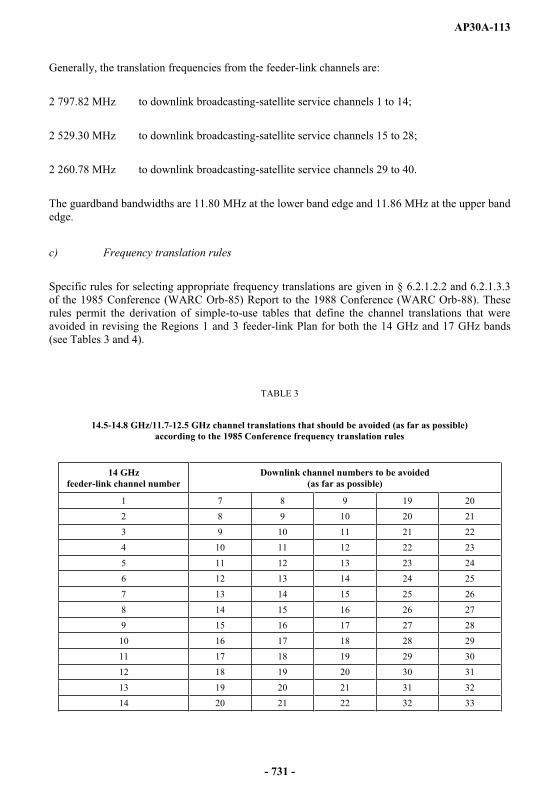
AP30A-113
Generally, the translation frequencies from the feeder-link channels are:
2 797.82 MHz to downlink broadcasting-satellite service channels 1 to 14;
2 529.30 MHz to downlink broadcasting-satellite service channels 15 to 28;
2 260.78 MHz to downlink broadcasting-satellite service channels 29 to 40.
The guardband bandwidths are 11.80 MHz at the lower band edge and 11.86 MHz at the upper band edge.
c) Frequency translation rules
Specific rules for selecting appropriate frequency translations are given in § 6.2.1.2.2 and 6.2.1.3.3 of the 1985 Conference (WARC Orb-85) Report to the 1988 Conference (WARC Orb-88). These rules permit the derivation of simple-to-use tables that define the channel translations that were avoided in revising the Regions 1 and 3 feeder-link Plan for both the 14 GHz and 17 GHz bands (see Tables 3 and 4).
TABLE 3
14.5-14.8 GHz/11.7-12.5 GHz channel translations that should be avoided (as far as possible) according to the 1985 Conference frequency translation rules
14 GHzfeeder-link channel number
Downlink channel numbers to be avoided (as far as possible)
1 7 8 9 19 202 8 9 10 20 213 9 10 11 21 224 10 11 12 22 235 11 12 13 23 246 12 13 14 24 257 13 14 15 25 268 14 15 16 26 279 15 16 17 27 2810 16 17 18 28 2911 17 18 19 29 3012 18 19 20 30 3113 19 20 21 31 3214 20 21 22 32 33
- 731 -

AP30A-114AP30A-114
TAB
LE 4
17.3
-18.
1 G
Hz/
11.7
-12.
5 G
Hz
chan
nel t
rans
latio
ns th
at sh
ould
be
avoi
ded
(as f
ar a
s pos
sibl
e) a
ccor
ding
to th
e 19
85 C
onfe
renc
e fr
eque
ncy
tran
slat
ion
rule
s
17G
Hz
feed
er-li
nk c
hann
el
num
ber
Dow
nlin
k ch
anne
l num
bers
to b
e av
oide
d(a
s far
as p
ossi
ble)
110
1112
1314
1516
1718
1920
2122
211
1213
1415
1617
1819
2021
2223
312
1314
1516
1718
1920
2122
2324
413
1415
1617
1819
2021
2223
2425
514
1516
1718
1920
2122
2324
2526
615
1617
1819
2021
2223
2425
2627
716
1718
1920
2122
2324
2526
2728
817
1819
2021
2223
2425
2627
2829
918
1920
2122
2324
2526
2728
2930
101
1920
2122
2324
2526
2728
2930
3111
12
2021
2223
2425
2627
2829
3031
3212
12
321
2223
2425
2627
2829
3031
3233
131
23
422
2324
2526
2728
2930
3132
3334
141
23
45
2324
2526
2728
2930
3132
3334
3515
12
34
56
2425
2627
2829
3031
3233
3435
3616
12
34
56
725
2627
2829
3031
3233
3435
3637
171
23
45
67
826
2728
2930
3132
3334
3536
3738
181
23
45
67
89
2728
2930
3132
3334
3536
3738
3919
12
34
56
78
910
2829
3031
3233
3435
3637
3839
4020
12
34
56
78
910
1129
3031
3233
3435
3637
3839
4021
12
34
56
78
910
1112
3031
3233
3435
3637
3839
4022
12
34
56
78
910
1112
1331
3233
3435
3637
3839
4023
12
34
56
78
910
1112
1314
3233
3435
3637
3839
4024
23
45
67
89
1011
1213
1415
3334
3536
3738
3940
253
45
67
89
1011
1213
1415
1634
3536
3738
3940
264
56
78
910
1112
1314
1516
1735
3637
3839
4027
56
78
910
1112
1314
1516
1718
3637
3839
4028
67
89
1011
1213
1415
1617
1819
3738
3940
297
89
1011
1213
1415
1617
1819
2038
3940
308
910
1112
1314
1516
1718
1920
2139
4031
910
1112
1314
1516
1718
1920
2122
4032
1011
1213
1415
1617
1819
2021
2223
3311
1213
1415
1617
1819
2021
2223
2434
1213
1415
1617
1819
2021
2223
2425
3513
1415
1617
1819
2021
2223
2425
2636
1415
1617
1819
2021
2223
2425
2627
3715
1617
1819
2021
2223
2425
2627
2838
1617
1819
2021
2223
2425
2627
2829
3917
1819
2021
2223
2425
2627
2829
3040
1819
2021
2223
2425
2627
2829
30 3
1
- 732 -
AP30A-115
3.2 Carrier-to-noise ratio
§ 3.3 of Annex 5 to Appendix 30 provides guidance for planning and the basis for the evaluation of the carrier-to-noise (C/N) ratios of the feeder-link and downlink Plans.
As guidance for planning, the reduction in quality in the downlink due to thermal noise in the feeder-link is taken as equivalent to a degradation in the downlink C/N ratio of approximately 0.5 dB not exceeded for 99% of the worst month.
For downlinks, as indicated in Appendix 30, the 1977 Conference (WARC SAT-77) adopted a C/Nvalue of 14.5 dB for 99% of the worst month at the edge of the service area. The required feeder-linkC/N is 24 dB for 99% of the worst month, at the edge of the service area, to produce an overall C/Nperformance of 14 dB.
3.3 Protection ratios
For planning in Regions 1 and 3 at the 1988 Conference (WARC Orb-88), the following protection ratios were applied for the purpose of calculating the feeder-link equivalent protection margins41:
co-channel protection ratio = 40 dB;
adjacent channel protection ratio = 21 dB.
The method for the calculation of the feeder-link equivalent protection margin is given in § 1.7.
For revising the Regions 1 and 3 feeder-link Plan at WRC-97, the corresponding values of aggregate protection ratio that were used to calculate the feeder-link equivalent protection margins which appear in the alternative formula for overall equivalent protection margin given in § 1.12 are specified in Recommendation ITU-R BO.1297, as follows42, 43:
co-channel protection ratio = 30 dB;
adjacent channel protection ratio = 22 dB. (WRC-2000)
_______________41 These protection ratio values were used for assignments notified, which are in conformity with this Appendix, brought into use, and for which the date of bringing into use has been confirmed to the Bureau before 27 October 1997.
42 These protection ratio values were used for assignments notified, which are in conformity with this Appendix, brought into use, and for which the date of bringing into use has been confirmed to the Bureau between 27 October 1997 and 12 May 2000. (WRC-2000)
43 These protection ratio values were used for protection of digital and analogue assignments from analogue emissions. (WRC-2000)
- 733 -
AP30A-116
However, it should be noted that the revision of the Regions 1 and 3 feeder-link Plan by WRC-97
equivalent protect 1.11 of Annex 5 to Appendix 30 and in § 1.12) using the following values of aggregate protection ratio:
co-channel = 23 dB;
adjacent channel = 15 dB. (WRC-03)
It was also specified that, for the revision of the Regions 1 and 3 feeder-link Plan, no overall co-channel single entry C/I ratio should be lower than 28 dB. (WRC-03)
Nevertheless, for assignments notified, which are in conformity with this Appendix, brought into use, and for which the date of bringing into use has been confirmed to the Bureau before 27 October 1997, the overall equivalent protection margins were calculated using a co-channel overall protection ratio of 30 dB and lower and upper overall adjacent channel protection ratios of 14 dB.
Revision of the Regions 1 and 3 feeder-link Plan at WRC-97 and planning at WRC-2000 were generally based on a set of reference parameters such as the average e.i.r.p., the reference earth station
dB contour, a bandwidth of 27 MHz and the predetermined value of C/N. The Regions 1 and 3 feeder-link Plan as established by WRC-2000 is generally based on the use of digital modulation. (WRC-2000)
WRC-2000 adopted for the protection of digital assignments from digital emissions the following protection ratio values to be applied for calculation of feeder-link equivalent protection margins of the WRC-2000 Regions 1 and 3 feeder-link Plan:
27 dB for co-channel signals;
22 dB for adjacent channel signals. (WRC-2000)
During planning at WRC-2000, these values were used for all assignments of the Regions 1 and 3feeder-link Plan and List, except those for which WRC-2000 adopted different values to be used in the planning process44. (WRC-03)
Protection masks and associated calculation methods for interference into broadcasting-satellite systems involving digital emissions shall be in accordance with Recommendation ITU-R BO.1293-2 (Annexes 1 and 245). (WRC-03)
_______________44 For analogue assignments, the protection ratios of WRC-97 (30 dB co-channel, 22 dB adjacent channel) were used. (WRC-2000)
45 Annex 3 of this Recommendation may be applied only in compatibility analysis for bilateral coordination between administrations. (WRC-03)
- 734 -
AP30A-117
3.4 Feeder-link e.i.r.p.
The level of e.i.r.p. of each feeder link is specified in Article 9A.
The level of e.i.r.p. specified in the Plan can only be exceeded under certain conditions explained in § 3.11 of this Annex (see also Article 5, § 5.1.1).
3.5 Transmitting antenna
3.5.1 Antenna diameter
The feeder-link Plan is based on an antenna diameter of 5 m for the band 17.3-18.1 GHz and 6 m for the band 14.5-14.8 GHz.
For all antenna diameters including antennas smaller than 5 m for the 17.3-18.1 GHz band and 6 mfor the 14.5-14.8 GHz band, the off-axis e.i.r.p. shall not exceed the limits indicated by Curve A in Fig. A of § 3.5.3 of this Annex for assignments notified, which are in conformity with this Appendix, brought into use, and for which the date of bringing into use has been confirmed to the Bureau before 27 October A for other assignments.
3.5.2 On-axis gain
The on-axis gain for the 5 m antenna at 17.3-18.1 GHz and for the 6 m antenna at 14.5-14.8 GHz is taken as 57 dBi.
3.5.3 Off-axis e.i.r.p. of transmitting antennas
The co-polar and cross-polar off-axis e.i.r.p. values used for the original 1988 feeder-link Plan in Regions 1 and 3 are shown by Curves A and B respectively in Fig. A46.
The corresponding off-axis e.i.r.p. values used for planning at WRC-97 are shown by Curves Aand B in Fig. A as specified in Recommendation ITU-R BO.1295.
3.5.4 Pointing accuracy
The Plan has been developed to accommodate a loss in gain of 1 dB due to earth station antenna mispointing.
The deviation of the antenna beam from its nominal pointing direction must not exceed a limit of 0.1° in any direction. Moreover, the angular rotation of the receiving beam about its axis must not exceed a limit of 1°; the limit on rotation is not necessary for beams of circular cross section using circular polarization.
_______________46 This antenna pattern is used in the revision of the Regions 1 and 3 Plan for assignments notified, which are in conformity with this Appendix, brought into use, and for which the date of bringing into use has been confirmed to the Bureau before 27 October 1997.
- 735 -
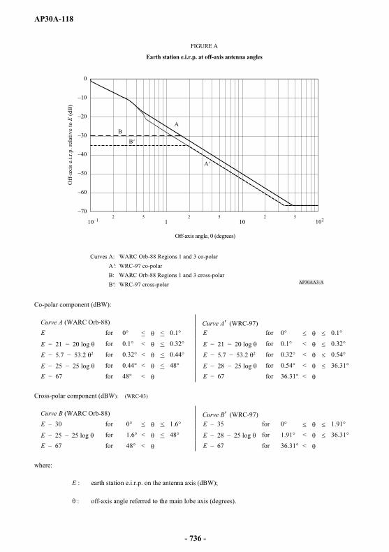
AP30A-118
Co-polar component (dBW):
Curve A (WARC Orb-88) Curve A (WRC-97)E for 0° < < 0.1° E for 0° 0.1°
E for 0.1° < < 0.32° E for 0.1° < 0.32°
E 2 for 0.32° < < 0.44° E 2 for 0.32° < 0.54°
E for 0.44° < < 48° E for 0.54° < 36.31°E for 48° < E for 36.31° <
Cross-polar component (dBW): (WRC-03)
Curve B (WARC Orb-88) Curve B (WRC-97)E 30 for 0° < < 1.6° E 35 for 0° 1.91°
E 25 25 log for 1.6° < < 48° E 28 25 log for 1.91° < 36.31°E 67 for 48° < E 67 for 36.31° <
where:
E : earth station e.i.r.p. on the antenna axis (dBW);
: off-axis angle referred to the main lobe axis (degrees).
AP30AA3-A
0
2 5 2 5 2 510 10210 1
A
B'
B
A'
FIGURE A
Earth station e.i.r.p. at off-axis antenna angles
Off
-axi
s e.i.
r.p. r
elat
ive
to E
(dB)
Off-axis angle, (degrees)
Curves A: WARC Orb-88 Regions 1 and 3 co-polar A': WRC-97 co-polar B: WARC Orb-88 Regions 1 and 3 cross-polar B': WRC-97 cross-polar
- 736 -
AP30A-119
3.6 Transmitter power
The maximum transmitter power delivered to the input of the antenna of the feeder-link earth station per 27 MHz television channel shall be such as to ensure that the e.i.r.p. envelope in § 3.5.3 is not exceeded except under certain conditions specified in § 3.11.
3.7 Satellite receiving antenna
3.7.1 Cross-section of receiving antenna beam
Planning has generally been based on beams of elliptical or circular cross-section. When the assignments are implemented, or when the Plan is modified, administrations may use non-elliptical (shaped) beams as described in Annex 2.
For planning purposes at WRC-97, an antenna diameter of 5 m for the band 17.3-18.1 GHz and 6 mfor the band 14.5-14.8 GHz were assumed.
The on-axis gain for the 5 m antenna at 17.3-18.1 GHz and for the 6 m antenna at 14.5-14.8 GHz is taken as 57 dBi.
If the cross-section of the receiving antenna beam is elliptical, the effective beamwidth 0 is a function of the angle of rotation q between the plane containing the satellite and the major axis of the beam cross-section and the plane in which the beamwidth is required.
The relationship between the maximum gain of an antenna and the half-power beamwidth can be derived from the expression:
Gm = 27 843/ab
where:
a and b are the angles (degrees) subtended at the satellite by the major and minor axes of the elliptical cross-section of the beam. An antenna efficiency of 55% is assumed.
3.7.2 Minimum beamwidth
A minimum value of 0.6° for the half-power beamwidth of the receiving antenna has been used for planning.
3.7.3 Reference patterns
The reference patterns for the co-polar and cross-polar components of the satellite receiving antenna used for planning at the 1988 Conference (WARC Orb-88) are given by Curves A and B respectively in Fig. B47.
_______________47 See footnote 46.
- 737 -
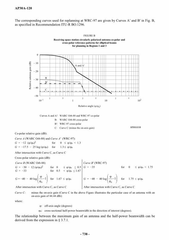
AP30A-120
The corresponding curves used for replanning at WRC-97 are given by Curves A and B in Fig. B, as specified in Recommendation ITU-R BO.1296.
Co-polar relative gain (dB):
Curve A (WARC Orb-88) and Curve A (WRC-97):G = / 0)2 for 0 / 0 < 1.3G = / 0) for 1.3 / 0
After intersection with Curve C, as Curve C
Cross-polar relative gain (dB):
Curve C: minus the on-axis gain (Curve C in the above Figure illustrates the particular case of an antenna with an on-axis gain of 44.44 dBi)
where: : off-axis angle (degrees)
0: cross-sectional half-power beamwidth in the direction of interest (degrees).
The relationship between the maximum gain of an antenna and the half-power beamwidth can be derived from the expression in § 3.7.1.
AP30AA3-B
0
BB'
C
10 1 10 1022 5 2 5 2 5
FIGURE BReceiving space station circularly polarized antenna co-polar and
cross-polar reference patterns for elliptical beamsfor planning in Regions 1 and 3
Rel
ativ
e an
tenn
a ga
in (d
B)
Relative angle ( / 0)
A and A'
Curves A and A': WARC Orb-88 and WRC-97 co-polarB: WARC Orb-88 cross-polar
B': WRC-97 cross-polarC: Curve C (minus the on-axis gain)
Curve B (WARC Orb-88) Curve B (WRC-97)G / 0)2 for 0 / 0 < 0.5G for 0.5 < / 0 < 1.67
G for 0 / 0 < 1.75
G 10
for 1.67 / 0 G 10
for 1.75 / 0
After intersection with Curve C, as Curve C After intersection with Curve C, as Curve C
- 738 -
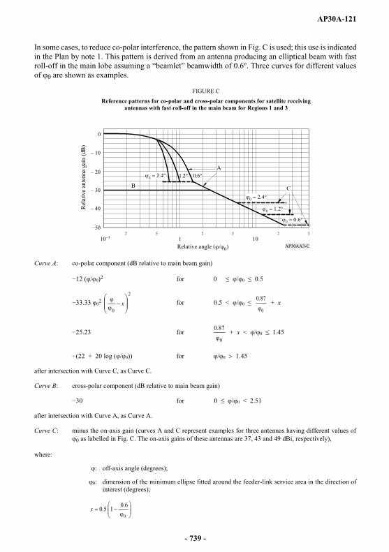
AP30A-121
In some cases, to reduce co-polar interference, the pattern shown in Fig. C is used; this use is indicated in the Plan by note 1. This pattern is derived from an antenna producing an elliptical beam with fast roll- idth of 0.6o. Three curves for different values of 0 are shown as examples.
Curve A: co-polar component (dB relative to main beam gain)
/ 0)2 for 0 / 0 0.5
022
0x for 0.5 < / 0
0
87.0 + x
for 0
87.0 + x < / 0 1.45
+ 20 log ( / 0)) for / 0 1.45
after intersection with Curve C, as Curve C.
Curve B: cross-polar component (dB relative to main beam gain)
30 for 0 / 0 < 2.51
after intersection with Curve A, as Curve A.
Curve C: minus the on-axis gain (curves A and C represent examples for three antennas having different values of 0 as labelled in Fig. C. The on-axis gains of these antennas are 37, 43 and 49 dBi, respectively),
where:
off-axis angle (degrees);
0: dimension of the minimum ellipse fitted around the feeder-link service area in the direction of interest (degrees);
0
6.015.0x
AP30AA3-C
A
CB
0
2 5 2 5 2 51 1010
FIGURE C
Reference patterns for co-polar and cross-polar components for satellite receivingantennas with fast roll-off in the main beam for Regions 1 and 3
Rela
tive
ante
nna
gain
(dB)
Relative angle ( 0)
- 739 -
AP30A-122
3.7.4 Pointing accuracy
The deviation of the receiving antenna beam from its nominal pointing direction must not exceed 0.1o
in any direction. Moreover, the angular rotation of the receiving beam about its axis must not exceed 1°; this limit is not necessary for beams of circular cross-section using circular polarization.
3.7.5 Composite beam (WRC-2000)
A composite beam represents a single beam (i.e. combining two or more elliptical beams at a given orbital position. In general, composite beams were used at WRC-2000 for administrations which had more than one beam at a given orbital position in the WRC-97 Regions 1 and 3 feeder-link Plan. (WRC-2000)
3.8 System noise temperature
The satellite system noise temperature values generally used in the Plan at the 1988 Conference (WARC Orb-88) are 1800 K for 17 GHz and 1500 K for 14 GHz48. For revising the Regions 1 and 3Plan at WRC-97 these values are 900 K for 17 GHz and 750 K for 14 GHz. A value of 600 K was used for the 17 GHz band in the revision of the Regions 1 and 3 Plan at WRC-2000. WRC-2000 did not change the value for the 14 GHz band. (WRC-03)
3.9 Polarization
In Regions 1 and 3, circular polarization was normally used for the purpose of planning the feeder-links.
3.2.3 of Annex 5 to Appendix 30.
For the planning of the broadcasting-satellite service, circular polarization is generally used. However, for implementation of assignments in the Regions 1 and 3 Plan, linear polarization may also be used subject to successful application of the modification procedure of Article 4. Linear polarization is defined in Recommendation ITU-R BO.1212. This Recommendation should be used when analysing linearly polarized signals.
_______________48 These system temperature values are still used for assignments notified, which are in conformity with this Appendix, brought into use, and for which the date of bringing into use has been confirmed to the Bureau before 27 October 1997.
- 740 -
AP30A-123
3.10 Automatic gain control
The downlink Plan was based on constant satellite output power. However, the feeder-link Plan does not take account of the effect of automatic gain control on board satellites. Up to 15 dB of automatic gain control is permitted, subject to no increase in interference to other satellite systems.
3.11 Power control
In Regions 1 and 3, a permitted increase which may be used to overcome rain fading for each assignment is included in the Plan.
In the calculation, in cases where satellites do not use common or adjacent channels cross-polarized to each other, the maximum permissible e.i.r.p. increase, which must not exceed 10 dB, corresponds to the amount of rain attenuation which occurs on the interfering feeder link.
3.11.1 Method for determination of the increase in e.i.r.p. during rain attenuation for an assignment over the Plan value
Condition to be observed
The increase in e.i.r.p. of the assignment studied must not entail an impairment of more than 0.5 dB of the feeder-link equivalent protection margin of any other assignment of any other administration.
Calculation method
Step 1: compile a list of all assignments of other administrations (A, B, C, . . .) in the same orbital position and positions within 6° (or further if no station is found within 6° arc) liable to suffer interference from the assignment studied.
Step 2: calculate the feeder-link equivalent protection margin of assignment A in free-space conditions, taking account of all interference sources affecting A at the worst test points, namely:
for assignment A: the point corresponding to the minimum C/N ratio;
for each interference source affecting A: the point corresponding to the maximum interference power affecting A.
- 741 -

AP30A-124
Step 3: introduce for the assignment studied the rain attenuation for 0.1% of the worst month and the corresponding rain depolarization value.
Step 4: recalculate the feeder-link equivalent protection margin of assignment A at the worst test points, namely:
for assignment A: the test point used in Step 2 above;
for the assignment studied: the test point corresponding to the maximum interference power affecting A.
At this stage, the e.i.r.p. of the assignment studied is that contained in the Plan.
Step 5: increase the e.i.r.p. of the assignment studied by 0.1 dB and recalculate the equivalent uplink margin of A as in Step 4 above.
Step 6: repeat the operation of Step 5 above until the equivalent uplink margin of assignment Ais impaired by more than 0.5 dB in relation to the value found under Step 2 above, or until the e.i.r.p. increase exceeds 10 dB or the rain attenuation (see Step 3). Adopt the e.i.r.p. increase in the preceding iteration step.
Step 7: repeat the operations in Step 2 to Step 6 above, considering the assignments B, C, . . .
Step 8: adopt the smallest of the increases in e.i.r.p. found under Step 6 above for the various assignments A, B, C, . . .
3.11.2 Propagation model
For the calculation of rain attenuation for 0.1% of the worst month, the model described in § 2.2 should be used. It shall be assumed that the 0.1% value is 3.3 times the 1% value (dB).
Rain depolarization shall be calculated on the basis of attenuation, using the method described in § 2.4.
- 742 -
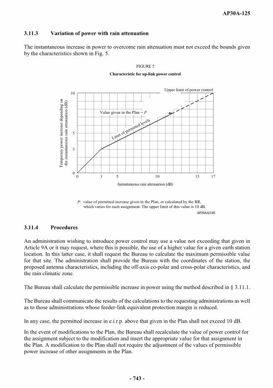
AP30A-125
3.11.3 Variation of power with rain attenuation
The instantaneous increase in power to overcome rain attenuation must not exceed the bounds given by the characteristics shown in Fig. 5.
3.11.4 Procedures
An administration wishing to introduce power control may use a value not exceeding that given in Article 9A or it may request, where this is possible, the use of a higher value for a given earth station location. In this latter case, it shall request the Bureau to calculate the maximum permissible value for that site. The administration shall provide the Bureau with the coordinates of the station, the proposed antenna characteristics, including the off-axis co-polar and cross-polar characteristics, and the rain climatic zone.
The Bureau shall calculate the permissible increase in power using the method described in § 3.11.1.
The Bureau shall communicate the results of the calculations to the requesting administrations as well as to those administrations whose feeder-link equivalent protection margin is reduced.
In any case, the permitted increase in e.i.r.p. above that given in the Plan shall not exceed 10 dB.
In the event of modifications to the Plan, the Bureau shall recalculate the value of power control for the assignment subject to the modification and insert the appropriate value for that assignment in the Plan. A modification to the Plan shall not require the adjustment of the values of permissible power increase of other assignments in the Plan.
AP30AA3-05
3 5 10 15 170
10
3
0
5
FIGURE 5
Characteristic for up-link power control
Tem
pora
ry p
ower
incr
ease
dep
endi
ng o
nth
e in
stan
tane
ous r
ain
atte
nuat
ion
(dB
)
Instantaneous rain attenuation (dB)
Limit of permitted levels
Upper limit of power control
P: value of permitted increase given in the Plan, or calculated by the BR, which varies for each assignment. The upper limit of this value is 10 dB.
Value given in the Plan = P
- 743 -
AP30A-126
3.12 (SUP - WRC-97)
3.13 Depolarization compensation
The Plan is developed without the use of depolarization compensation. Depolarization compensation is permitted only to the extent that interference to other satellites does not increase by more than 0.5 dB49 relative to that calculated in the feeder-link Plan.
3.14 Amplitude-modulation to phase-modulation conversion
The degradation caused by AM to PM conversion was taken into account when calculating the carrier-to-noise ratio of the feeder link. A value of 2.0 dB was allowed.
3.15 Orbit positions
The Plan is generally based on the use of a regular spacing of 6°. The orbital positions are those given in the Plan. (WRC-03)
3.16 Satellite station-keeping
Space stations in the broadcasting-satellite service must be maintained in position with an accuracy equal to or better than 0.1° in the E-W direction. For such space stations, the maintenance of the tolerance 0.1° in the N-S direction is recommended but is not a requirement.
3.17 Orbital separation limit for interference calculation (WRC-2000)
WRC-2000 has adopted the use of an orbital separation limit for interference calculation in Regions 1 and 3. Beyond this limit no interference was taken into account. (WRC-2000)
Initially, the values used for the orbital separation limit were 15° for co-polar and 9° for cross-polar emissions. At a later stage, the unique value of the orbital separation limit of 9° was adopted by WRC-2000. (WRC-2000)
_______________49 This margin has to be shared between power control effects and depolarization compensation effects when both are involved (see § 3.11).
- 744 -
AP30A-127
4 Basic technical characteristics for Region 2
4.1 Translation frequency and guard bands
The feeder-link Plan is based on the use of a single frequency translation of 5.1 GHz between the 17 GHz feeder-link channels and the 12 GHz downlink channels. Other values of the translation frequency may be used, provided that the corresponding channels have been assigned to the space station of the administration concerned.
With a single value frequency translation between the feeder-link frequency band (17.3-17.8 GHz) and the downlink frequency band (12.2-12.7 GHz), the guard bands present in the downlink Plan result in corresponding bandwidths of 12 MHz at the upper and lower feeder-link band edges. These feeder-link guard bands may be used to provide space operation functions in accordance with No. 1.23in support of the operation of geostationary-satellite networks in the broadcasting-satellite service. (WRC-03)
4.2 Carrier-to-noise ratio
Section 3.3 of Annex 5 to Appendix 30 provides guidance for planning and the basis for the evaluation of the carrier-to-noise ratios of the feeder-link and downlink Plans.
As a guidance for planning, the reduction in quality in the downlink due to thermal noise in the feeder link is taken as equivalent to a degradation in the downlink carrier-to-noise ratio of approximately 0.5 dB not exceeded for 99% of the worst month.
4.3 Carrier-to-noise ratio
Section 3.4 of Annex 5 to Appendix 30 provides guidance for planning for the contribution of the feeder-link co-channel interference to the overall co-channel carrier-to-interference ratio. However, the feeder-link and downlink Plans are evaluated on the overall equivalent protection margin which includes the combined downlink and feeder-link contributions. Definitions given in § 1.7, 1.8, 1.9, 1.10 and 1.11 of this Annex and the protection ratios given in Section 3.4 of Annex 5 to Appendix 30are used in the analysis of the Plans.
For the adjacent channels, the Plan is based on an orbital separation of 0.4° between nominally co-located satellites having cross-polarized adjacent channel assignments.
For the second adjacent channels, the Plan is based on a 10 dB improvement on the feeder-link carrier-to-interference ratio due to the satellite receive filtering.
- 745 -
AP30A-128
4.4 Transmitting antenna
4.4.1 Antenna diameter
The feeder-link Plan is based on an antenna diameter of 5 m.
The minimum antenna diameter permitted in the Plan is 2.5 m. However, the feeder-link carrier-to-noise ratio and carrier-to-interference ratio resulting from the use of antennas with diameters smaller than 5 m would generally be less than those calculated in the Plan.
The use of antennas larger than 5 m, with corresponding values of on-axis e.i.r.p. higher than the planned value (indicated in § 4.4.3) but without augmented off-axis e.i.r.p., is permitted if the orbital separation between the assigned orbital location of the administration and the assigned orbital location of any other administration is greater than 0.5°.
Antennas with diameters larger than 5 m can also be implemented if the above orbital separation is less than 0.5° and if the e.i.r.p. of the desired feeder-link earth station does not exceed the planned value of e.i.r.p.
If the above orbital separation is less than 0.5° and if the e.i.r.p. of the desired feeder-link earth station exceeds the planned value, agreement between administrations is required.
4.4.2 Transmitting antenna reference patterns (WRC-03)
The co-polar and cross-polar reference patterns of transmitting antennas used for planning in Region 2are given in Fig. 6.
4.4.3 Antenna efficiency
The Plan is based on an antenna efficiency of 65%. The corresponding on-axis gain for an antenna having a 5 m diameter is 57.4 dBi at 17.55 GHz, and the corresponding value of e.i.r.p. used for planning purposes is 87.4 dBW.
4.4.4 Pointing accuracy
The Plan has been developed to accommodate a loss in gain due to earth station antenna mis-pointing of 1 dB. Under no circumstances shall the Plan allow for a mis-pointing angle greater than 0.1°.
- 746 -
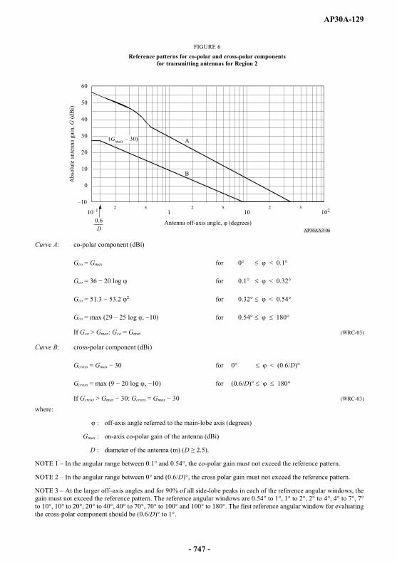
AP30A-129
Curve A: co-polar component (dBi)
Gco = Gmax for 0° < 0.1°
Gco = for 0.1° < 0.32°
Gco = for 0.32° < 0.54°
Gco = max (29 25 log ) for 0.54° 180°
If Gco > Gmax: Gco = Gmax (WRC-03)
Curve B: cross-polar component (dBi)
Gcross = Gmax 30 for 0° < (0.6/D)°
Gcross ) for (0.6/D)° 180°
If Gcross > Gmax : Gcross = Gmax (WRC-03)
where:
: off-axis angle referred to the main-lobe axis (degrees)
Gmax : on-axis co-polar gain of the antenna (dBi)
D : diameter of the antenna (m) (D
NOTE 1 In the angular range between 0.1° and 0.54°, the co-polar gain must not exceed the reference pattern.
NOTE 2 In the angular range between 0° and (0.6/D)°, the cross polar gain must not exceed the reference pattern.
NOTE 3 At the larger off axis angles and for 90% of all side-lobe peaks in each of the reference angular windows, the gain must not exceed the reference pattern. The reference angular windows are 0.54° to 1°, 1° to 2°, 2° to 4°, 4° to 7°, 7° to 10°, 10° to 20°, 20° to 40°, 40° to 70°, 70° to 100° and 100° to 180°. The first reference angular window for evaluating the cross-polar component should be (0.6/D)° to 1°.
AP30AA3-06
60
40
50
30
20
10
0
2 5 2 5 2 510 1 10 102
B
A
FIGURE 6Reference patterns for co-polar and cross-polar components
for transmitting antennas for Region 2
Antenna off-axis angle, (degrees)
Abs
olut
e an
tenn
a ga
in, G
(dB
i)
0.6D
(Gmax
- 747 -

AP30A-130
4.5 Transmit power
The maximum transmit power delivered to the input of the antenna of the feeder-link earth station is 1 000 W per 24 MHz television channel. This level of power can only be exceeded under certain conditions specified in § 4.10.
4.6 Receiving antenna
4.6.1 Cross-section of receiving antenna beam
Planning has been based on beams of elliptical or circular cross-section. When the assignments are implemented, or when the Plan is modified, administrations may use non-elliptical or shaped beams.
If the cross-section of the receiving antenna beam is elliptical, the effective beamwidth 0 is a function of the angle of rotation q between the plane containing the satellite and the major axis of the beam cross-section and the plane in which the beamwidth is required.
The relationship between the maximum gain of an antenna and the half-power beamwidth can be derived from the expression:
Gm = 27 843/ab
or
Gm (dB) = 44.44 10 log a 10 log b
where:
a and b are the angles (degrees) subtended at the satellite by the major and minor axes of the elliptical cross-section of the beam.
An antenna efficiency of 55% is assumed.
4.6.2 Minimum beamwidth
A minimum value of 0.6° for the half-power beamwidth of the receiving antenna has been agreed on for planning.
4.6.3 Receiving antenna reference patterns (WRC-03)
The reference patterns for the co-polar and cross-polar components of the satellite receiving antenna used in preparing the Plan are given in Fig. 7.
Where it was necessary to reduce interference, the pattern shown in Fig. 8 was used; this use will beindicated in the Plan by an appropriate symbol. This pattern is derived from an antenna producing an elliptical beam with fast roll-off in the main lobe. Three curves for different values of 0 are shown as examples.
- 748 -
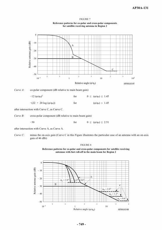
AP30A-131
Curve A: co-polar component (dB relative to main beam gain)
0)2 for 0 ( 0) 1.45
+ 20 log ( 0)) for ( 0) 1.45
after intersection with Curve C, as Curve C.
Curve B: cross-polar component (dB relative to main beam gain)
for 0 ( 0) 2.51
after intersection with Curve A, as Curve A.
Curve C: minus the on-axis gain (Curve C in this Figure illustrates the particular case of an antenna with an on-axis gain of 46 dBi)
AP30AA3-07
0
2 5 2 5 2 51 10 10210
B
C
A
Rela
tive
ante
nna
gain
(dB)
Relative angle ( 0)
FIGURE 7Reference patterns for co-polar and cross-polar components
for satellite receiving antenna in Region 2
AP30AA3-08
A
CB
0
2 5 2 5 2 51 1010
Rela
tive
ante
nna
gain
(dB)
Relative angle ( 0)
FIGURE 8
Reference patterns for co-polar and cross-polar components for satellite receivingantennas with fast roll-off in the main beam for Region 2
- 749 -
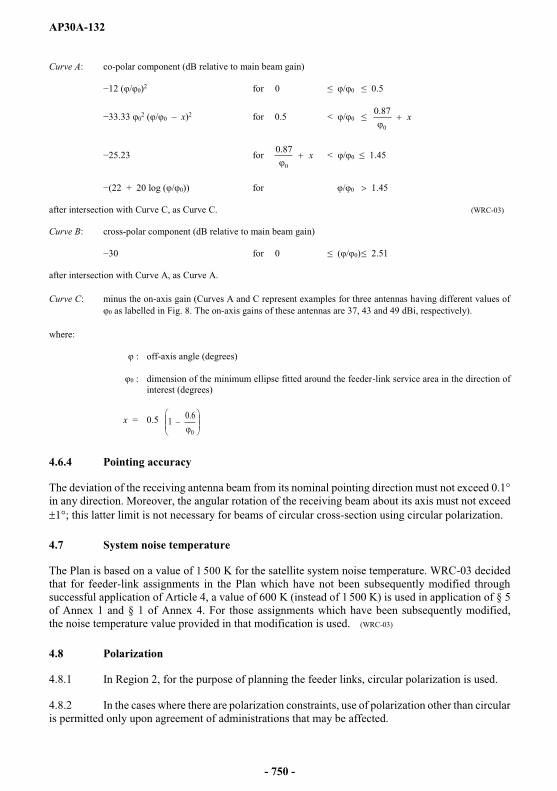
AP30A-132
Curve A: co-polar component (dB relative to main beam gain)
/ 0)2 for 0 / 0 0.5
02 ( / 0 x)2 for 0.5 < / 0 x
0
87.0
for x0
87.0 < / 0 1.45
+ 20 log ( / 0)) for / 0 1.45
after intersection with Curve C, as Curve C. (WRC-03)
Curve B: cross-polar component (dB relative to main beam gain)
for 0 ( / 0) 2.51
after intersection with Curve A, as Curve A.
Curve C: minus the on-axis gain (Curves A and C represent examples for three antennas having different values of as labelled in Fig. 8. The on-axis gains of these antennas are 37, 43 and 49 dBi, respectively).
where:
: off-axis angle (degrees)
: dimension of the minimum ellipse fitted around the feeder-link service area in the direction of interest (degrees)
x = 0.50
6.01
4.6.4 Pointing accuracy
The deviation of the receiving antenna beam from its nominal pointing direction must not exceed 0.1° in any direction. Moreover, the angular rotation of the receiving beam about its axis must not exceed
1°; this latter limit is not necessary for beams of circular cross-section using circular polarization.
4.7 System noise temperature
The Plan is based on a value of 1 500 K for the satellite system noise temperature. WRC-03 decided that for feeder-link assignments in the Plan which have not been subsequently modified through successful application of Article 4, a value of 600 K (instead of 1 500 K) is used in application of § 5 of Annex 1 and § 1 of Annex 4. For those assignments which have been subsequently modified, the noise temperature value provided in that modification is used. (WRC-03)
4.8 Polarization
4.8.1 In Region 2, for the purpose of planning the feeder links, circular polarization is used.
4.8.2 In the cases where there are polarization constraints, use of polarization other than circular is permitted only upon agreement of administrations that may be affected.
- 750 -
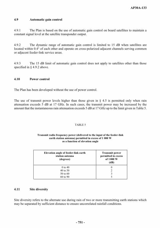
AP30A-133
4.9 Automatic gain control
4.9.1 The Plan is based on the use of automatic gain control on board satellites to maintain a constant signal level at the satellite transponder output.
4.9.2 The dynamic range of automatic gain control is limited to 15 dB when satellites are located within 0.4° of each other and operate on cross-polarized adjacent channels serving common or adjacent feeder-link service areas.
4.9.3 The 15 dB limit of automatic gain control does not apply to satellites other than those specified in § 4.9.2 above.
4.10 Power control
The Plan has been developed without the use of power control.
The use of transmit power levels higher than those given in § 4.5 is permitted only when rain attenuation exceeds 5 dB at 17 GHz. In such cases, the transmit power may be increased by the amount that the instantaneous rain attenuation exceeds 5 dB at 17 GHz up to the limit given in Table 5.
TABLE 5
Transmit radio frequency power (delivered to the input of the feeder-linkearth station antenna) permitted in excess of 1 000 W
as a function of elevation angle
Elevation angle of feeder-link earthstation antenna
(degrees)
Transmit power permitted in excess
of 1 000 W(dB)
0 to 4040 to 5050 to 6060 to 90
0235
4.11 Site diversity
Site diversity refers to the alternate use during rain of two or more transmitting earth stations which may be separated by sufficient distance to ensure uncorrelated rainfall conditions.
- 751 -

AP30A-134
The use of site diversity is permitted and is considered to be an effective technique for maintaining high carrier-to-noise ratio and carrier-to-interference ratio during periods of moderate to severe rain attenuation. However, the Plan is not based on the use of site diversity.
4.12 Depolarization compensation
The Plan is developed without the use of depolarization compensation. Depolarization compensation is permitted only to the extent that interference to other satellites does not increase by more than 0.5 dB relative to that calculated in the feeder-link Plan.
4.13 Minimum separation between satellites
Figure 9 illustrates two adjacent clusters of satellites separated by 0.9° between the centres of the clusters. A identifies a satellite of administration . A cluster is formed by two or more satellites separated by 0.4° and located at two nominal orbital positions as specified in the Plan; one position for right-hand polarized channels and the other position for left-hand polarized channels.
4.13.1 Satellites of the same cluster
The Plan is based on an orbital separation of 0.4° between satellites having cross-polarized adjacent channels (i.e. satellites located at +within a cluster may be located at any orbital position within the cluster, requiring only the agreement of the other administrations having satellites sharing the same cluster. Such orbital positioning of satellites within a cluster is illustrated in Fig. 9 by some of the satellites A5, A6 and A7.
The station-keeping tolerance of 0.1° indicated in § 3.11 of Annex 5 to Appendix 30 must be applied to satellites located at any position within the 0.4° wide cluster.
4.13.2 Satellites of different clusters
In the Plan, the orbital separation between the centres of adjacent clusters of satellites is at least 0.9°. The value of 0.9° is also the minimum orbital separation to provide flexibility in the implementation of feeder links indicated in § 4.4.1 without the need for an agreement (see § 4.13.1).
- 752 -
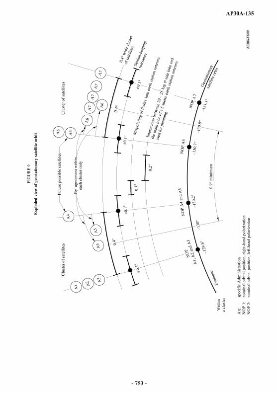
AP30A-135
AP3
0AA
3-09
A1 A
2 A3
A5
A5
A4
A6
A6
A6
A7
A7
A7
A7
A6
FIG
UR
E 9
Exp
lode
d vi
ew o
f geo
stat
iona
ry sa
telli
te o
rbit
Futu
re p
ossi
ble
sate
llite
s
each
clu
ster
onl
yB
y a
gree
men
t with
in
Clu
ster
of s
atel
lites
Clu
ster
of s
atel
lites
0.4°
±0.1
°
±0.1
°±0
.1°
±0.1
°0.
1°
0.2°
0.4°
wid
e clu
ster
of sa
telli
tes
Stat
ion-
keep
ing
tole
ranc
e
Misp
oint
ing
of fe
eder
-link
ear
th st
atio
n an
tenn
a
side
lobe
and
the
mai
n lo
be o
f a 5
-met
re e
arth
stat
ion
ante
nna
used
for p
lann
ing
Geo
statio
nary
sate
llite
orb
it0.
9° m
inim
um
NO
P
A1,
A2
and
A3
NO
P A
4 an
d A
5N
OP
A6
NO
P A
7
With
ina
clus
ter
Exam
ple:
A:
spec
ific
Adm
inis
tratio
nN
OP
1:
nom
inal
orb
ital p
ositi
on, r
ight
-han
d po
lariz
atio
nN
OP
2:
nom
inal
orb
ital p
ositi
on, l
eft-h
and
pola
rizat
ion
0.4°
- 753 -

AP30A-136
ANNEX 4 (REV.WRC-15)
Criteria for sharing between services
1 Threshold values for determining when coordination is required between, on one hand, transmitting space stations in the fixed-satellite service or the broadcasting-satellite service and, on the other hand, a receiving space station in the feeder-link Plan or List or a proposed new or modified receiving space station in the List, in the frequency bands 17.3-18.1 GHz (Regions 1 and 3) and in the feeder-link Plan or a proposed modification to the Plan in the frequency band 17.3-17.8 GHz (Region 2) (WRC-03)
With respect to § 7.1, Article 7, coordination of a transmitting space station in the fixed-satellite service or in the broadcasting-satellite service with a receiving space station in a broadcasting-satellite service feeder link in the Regions 1 and 3 feeder-link Plan or List, or a proposed new or modified receiving space station in the List, or in the Region 2 feeder-link Plan or proposed modification to the Plan is required when the power flux-density arriving at the receiving space station of a broadcasting-satellite service feeder link of another administration would cause an increase in the noise temperature of the feeder-link space station which exceeds a threshold value of Ts / Ts corresponding to 6%. Ts/Ts is calculated in accordance with Case II of the method given in Appendix 8. (WRC-03)
2 Threshold values for determining when coordination is required between transmitting feeder-link earth stations in the fixed-satellite service in Region 2 and a receiving space station in the Regions 1 and 3feeder-link Plan or List or a proposed new or modified receiving space station in the List, in the frequency band 17.8-18.1 GHz (WRC-03)
With respect to § 7.1, Article 7, coordination of a transmitting feeder-link earth station in the fixed-satellite service with a receiving space station in a broadcasting-satellite feeder link in the Regions 1 and 3 feeder-link Plan or List, or a proposed new or modified receiving space station in the List, is required when the power flux density arriving at the receiving space station of a broadcasting-satellite service feeder link of another administration would cause an increase in the noise temperature of the feeder-link space station which exceeds a threshold value of T/T corresponding to 6%, where T/Tis calculated in accordance with the method given in Appendix 8, except that the maximum power densities per hertz averaged over the worst 1 MHz are replaced by power densities per hertz averaged over the necessary bandwidth of the feeder-link carriers. (WRC-03)
- 754 -

AP30A-137
3 Threshold values for determining when coordination is required between transmitting earth stations in the fixed-satellite service in the frequency band 14.5-14.75 GHz (in countries listed in Resolution 163 (WRC-15)) and 14.5-14.8 GHz (in countries listed in Resolution 164(WRC-15)) not for feeder links for the broadcasting-satellite service and a receiving space station subject to a Plan in the frequency band 14.5-14.8 GHz (WRC-15)
With respect to § 7.1, Article 7, coordination of a transmitting earth station in the fixed-satellite service with a receiving space station in a broadcasting-satellite feeder link in the Regions 1 and 3feeder-link Plan or List, or a proposed new or modified receiving space station in the List, is required when the power flux-density arriving at the receiving space station of a broadcasting-satellite service feeder link of another administration exceeds the value of:
GRx dB(W/(m2 Hz)) with regard to the assignment in the Regions 1 and 3 feeder-link Plan or
GRx dB(W/(m2 Hz)), with regard to the assignment included in the feeder-link List or for which complete Appendix 4 information has been received by the Radiocommunication Bureau in accordance with the provisions of § 4.1.3,
where GRx is the relative receive antenna gain of the space station subject to a Plan at the location of the transmitting earth station in the fixed-satellite service not for feeder links for the broadcasting-satellite service. (WRC-15)
- 755 -