Embed Size (px)
Citation preview

International Journal of Robotics and Automation (IJRA)
Vol.9, No.3, September 2020, pp. 196~210
ISSN: 2089-4856, DOI: 10.11591/ijra.v9i3.pp196-210 196
Journal homepage: http://ijra.iaescore.com
Prototype development of tethered underwater robot
for underwater vessel anchor release
Ezeofor Chukwunazo Joseph1, Georgewill Oyengiye Moses
2
1Department of Electrical and Electronic Engineering, University of Port Harcourt, Nigeria 2Saro Wiwa Polytechnic Bori, Nigeria
Article Info ABSTRACT
Article history:
Received Mar 4, 2020
Revised Mar 31, 2020
Accepted Apr 29, 2020
Tethered underwater robot (TUR) for underwater vessel anchor release is
presented. In off-shore oil and gas enviromnment, there has been series of
reported cases on stuck vessel anchors after mooring operations and divers
are sent to release these anchors for the vessels to be in motion. The use of
divers to perform such function is very risky because of human limitation
and some divers have been reported dead on the process due to high pressure
underwater or being attacked by underwater wide animals. This has caused
very serious panic to the vessel owners and hence, this work is aimed to
develop TUR that would be used by the vessel operators instead of divers to
release the stuck anchor without loss. The underwater robot system
comprises of three basic sections namely graphical user control interface
(GUCI) that would be installed in the operator’s laptop, the WiFi LAN router
for network connection, and TUR system hardware and software. Each of
these sections was strictly designed. Various high-level programming
languages were employed to design the GUCI and code the interface buttons,
robot controller program codes etc. The implementation carried out and
the prototype system tested in the University of Port Harcourt’s swimming
pool of 6m depth for validation. The robot performed extremely good in
swimming and release of constructed anchor underwater.
Keywords:
Anchor
Divers
Off-shore environment
ROV
Sea vessel
This is an open access article under the CC BY-SA license.
Corresponding Author:
Ezeofor Chukwunazo Joseph,
Department of Electrical and Electronic Engineering,
University of Port Harcourt
Choba, Port Harcourt, Rivers State, Nigeria.
Email: [email protected]
1. INTRODUCTION
Undersea robotics has shown an increasing interest in the last 50 years for oceanic cartography, sea
exploration and underwater oil extraction that has led to the creation of an underwater vehicle to be
controlled from distance [1–4]. Recently, underwater robots have been used for various tasks such as
underwater data collection, underwater surveillance, underwater structure inspection, pipe handling in
drilling operations, pipe inspection, in-pipe inspection robots (lPIRs), ship hull inspection, ocean exploration,
maintenance of underwater equipment etc. [5–9]. Remotely operated underwater vehicles shortened as ROVs
are tethered and manned underwater vehicle used to perform some certain functions underwater. The main
benefits of using underwater robotic vehicles could be removing divers from the dangers of the undersea
space and reduction in cost of exploration of deep seas.
In oil and gas offshore and marine environments in Nigeria, vessels transporting crudes are always
anchored during crudes offloading period at the sea port. There has been series of reported cases of trapped
anchors used to tension vessels during loading/offloading or mooring operation in the sea. The vessel anchor
Int J Rob & Autom ISSN: 2089-4856
Prototype development of tethered underwater robot for underwater vessel... (Ezeofor Chukwunazo Joseph)
197
might get trapped after operation and, for as long as the anchor is hooked, the vessel cannot move. Personnel
on duty often find it difficult to remove the trapped anchor after mooring operation or after waiting for its
offloading turn. The sea divers would typically be sent to release the anchor, depending on the depth of
the water which sometimes may be very difficult to release. When the situation seems so difficult, the vessel
anchor would be cut-off which is a huge loss to the vessel owners. To prevent any further delay of
the trapped vessel or loss to its anchor as observed, a remotely operated underwater robot prototype that
would release the vessel anchor is developed.
The following researched works were reviewed as stated:
- In 2015, Vedachalam et al [10] developed a 500 m depth rated remotely operated vehicle (Prove 500) for
carrying out scientific research in shallow waters and in challenging polar regions. The vehicle with
dimensions of 0.96 m × 0.61 m × 0.63 m and weighing 175 kg in air is designed for a speed of 3 knots
at an electric power input of 5 kW. The vehicle which is powered by 300 V DC through the 500 m
length of a neutrally buoyant electro-optic umbilical communicates with the surface console through
the redundant fiber optic cores of the umbilical. The developed vehicle is tested for its hydrodynamic
stability, low temperature performance in the in-house test facilities and for navigation at the Idukki
Lake in Kerala, where the vehicle is navigated at a depth of 106 m at 2 knots speed with the navigation
system's position error of less than 5 % in the dead reckoning mode. The vehicle is being equipped with
accessories for carrying out research in polar regions.
- In [11], studies showed the development of an underwater ROV with fuzzy logic motion control for
a shallow water environment i.e. up to 10 m depth. The ROV was developed with the associated
electronics for motion and power control. The control electronics are mounted inside the ROV main body
and communicated with via a tethered cable running from the surface which also carries the required
power. The ROV also has a camera for obtaining video and a set of LED lights for illumination. The main
controlling unit of the electronics is a Raspberry pi microcomputer which also operates the video. Test
trials of the ROV underwater were conducted in a laboratory water tank to a depth of about 1.5 m. Very
satisfactory operation was achieved. Some drawbacks and possible improvements were identified during
these tests and addressed in the second phase with the introduction of fuzzy logic for motion control.
- According to [1], Ahmad et al developed remotely operated vehicle (D20-ROV) for anode ship hull
inspection in 2017. This D20-ROV has three thrusters to control the maneuvering forward, reverse, left,
right, raise and submerged. The vehicle with dimensions of 0.5 m × 0.46 m × 0.22 m and weighing 15 kg
in the air is design for a speed around 3knots and it is powered by 16VDC on-board battery.
The umbilical transmits and receives the data through the 20-meter length by universal serial bus (USB)
cable to communicate with the operator at the control room. A real-time streaming camera and command
from a surface room were able to do a visual inspection of the vessels.
- A full-fledged robot (HYDROBOT) for underwater surveillance and survey was developed in 2018 [12].
Underwater surveillance is a new emerging technology as a promising field of research in recent years.
The potential applications include marine investigation, ocean exploration etc. The tasks to be carried out
by the robot would be detecting and mapping submerged wrecks, rocks and obstructions that could hinder
the navigation systems such as in commercial and recreational vessels. HYDROBOT is made up of
polyvinyl chloride pipes and is balanced by the principle of center of gravity. This structure is capable of
rotating in 360 degrees as well as changing the depth according to the user. The underwater video footage
is taken by camera for the identification of underwater life. Sensors such as the accelerometer, hall effect
sensor, and temperature sensor were used to make it more efficient for research and surveillance.
2. RESEARCH METHOD
The research method adopted is top-down approach which splits the entire TUR system into
hardware, software and mechanical systems (Figure 1). The software system includes graphical user control
interface (GUCI) and robot control program codes which are written using various high-level programming
languages in order to achieve the desired result. Mechanical system is made up of PVC materials that are
used to form system casing.
2.1. Hardware system
The hardware system comprises of the tethered underwater robot (TUR) and WiFi LAN router.
2.1.1. TUR system
TUR system consists of several subsystems such as power, communication, sensor,
propulsion, control, buoyancy, frame and actuators. The block diagram of the TUR system showcasing all
the components and their interconnection is shown in Figure 2.

ISSN:2089-4856
Int J Rob & Autom, Vol. 9, No. 3, September 2020 : 196 – 210
198
Figure 1. Breakdown structure of ROV system
Figure 2. Block diagram of the TUR for underwater anchor release
ROV SYSTEM
TUR SYSTEM GUCI SYSTEM MECHANICAL
SYSTEM
Sensors
Video
Camera
Arduino
Controller 1
Raspberry Pi 3
Controller 2 Thrusters
Ethernet +
Router
Robotic
Gripper
Battery + Power
Distribution
GUCI
Design
Software
GUCI
Programming
Language
XAML
Language C#
Language
LED
Hardware Embedded
Software
C++ Language
BASH
Shell script
Python for
Linux Raspberry

Int J Rob & Autom ISSN: 2089-4856
Prototype development of tethered underwater robot for underwater vessel... (Ezeofor Chukwunazo Joseph)
199
- Power panel: This section composed of LiPo battery, power distribution board and battery charger as
shown in Figure 3. All are integrated to ensure effective distribution of power to every unit of the system.
Figure 3. TUR Power supply panel
- Communication panel: Ethernet cable and Linksys router (Figure 4) form the communication devices of
the system. Router distributes the network within the communicating devices and ethernet is used to
communicate data from the user to the robot underwater and vice versa.
(a) (b)
Figure 4. Communication devices of the system:
(a) cat 6 ethernet cable and (b) TP-link wireless router 2.4 GHz
- Sensors: this section consists of ultrasonic sensor, inertia measurement unit (IMU) , camera and float
switch (Figure 5) for different purposes. With these sensors, robot can video underwater environments,
see inside the water, sink and float.
(a) (b) (c)
Figure 5. TUR sensors: (a) waterproof ultrasonic sensor, (b) vertical float switches, and (c) camera
- Control system: This section comprises of Raspberry Pi and Arduino Mega (Figure 6). Both are used to
control the entire system. Raspberry pi does image and video processing and transmit the video footage to
the user via ethernet cable. The Arduino mega does process the sensors signal and actuate other devices to
perform their fucntions.
Lipo Battery
Power Distribution Board
Digital Balance Charger

ISSN:2089-4856
Int J Rob & Autom, Vol. 9, No. 3, September 2020 : 196 – 210
200
(a) (b)
Figure 6. Controllers for the control system: (a) Raspberry Pi 3 Model B+ and (b) Arduino Mega 1280
- Thruster and nozzle: These devices are responsible for the robot motion underwater. The BLHeli device
amplifies the current from the Arduino Mega to be adequate to power the thruster. The force that propels
the robot system is provided by the thruster as shown in Figure 7.
(a) (b) (c)
Figure 7. System thruster and nozzle: (a) BLHeli current amplifier,
(b) waterproof thruster, and (c) thruster nozzle
- TUR actuator & end-effector: The TUR servo motor is used to actuate the end-effector (gripper) to
release the trapped anchor underwater as shown in Figure 8.
(a) (b)
Figure 8. Actuators of the TUR system: (a) robot clamp gripper and (b) waterproof robot servo
- Indicator & light display: The indicator is used by the system to check the percentage use of
the battery and relate to the user. Also, the swimming pool light is used by the robot to see while
performing function underwater as shown in Figure 9.
(a) (b)
Figure 9. Battery indicator and swimming pool light:
(a) LiPo battery voltage indicator and (b) waterproof swimming pool light
Int J Rob & Autom ISSN: 2089-4856
Prototype development of tethered underwater robot for underwater vessel... (Ezeofor Chukwunazo Joseph)
201
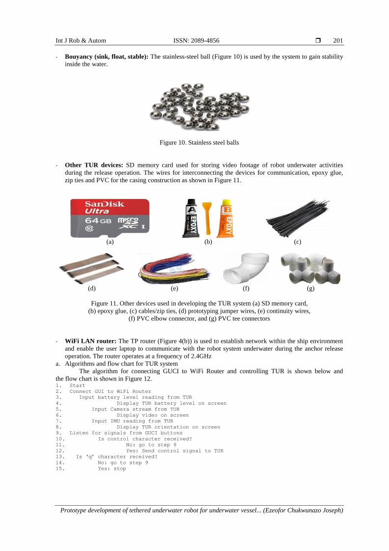
- Bouyancy (sink, float, stable): The stainless-steel ball (Figure 10) is used by the system to gain stability
inside the water.
Figure 10. Stainless steel balls
- Other TUR devices: SD memory card used for storing video footage of robot underwater activities
during the release operation. The wires for interconnecting the devices for communication, epoxy glue,
zip ties and PVC for the casing construction as shown in Figure 11.
(a) (b) (c)
(d) (e) (f) (g)
Figure 11. Other devices used in developing the TUR system (a) SD memory card,
(b) epoxy glue, (c) cables/zip ties, (d) prototyping jumper wires, (e) continuity wires,
(f) PVC elbow connector, and (g) PVC tee connectors
- WiFi LAN router: The TP router (Figure 4(b)) is used to establish network within the ship environment
and enable the user laptop to communicate with the robot system underwater during the anchor release
operation. The router operates at a frequency of 2.4GHz
a. Algorithms and flow chart for TUR system
The algorithm for connecting GUCI to WiFi Router and controlling TUR is shown below and
the flow chart is shown in Figure 12. 1. Start
2. Connect GUI to WiFi Router
3. Input battery level reading from TUR
4. Display TUR battery level on screen
5. Input Camera stream from TUR
6. Display video on screen
7. Input IMU reading from TUR
8. Display TUR orientation on screen
9. Listen for signals from GUCI buttons
10. Is control character received?
11. No: go to step 9
12. Yes: Send control signal to TUR
13. Is ‘q’ character received?
14. No: go to step 9
15. Yes: stop

ISSN:2089-4856
Int J Rob & Autom, Vol. 9, No. 3, September 2020 : 196 – 210
202
Figure 12. Flow chart of the graphical user control interface of the TUR system
2.1.2. TUR graphical user control interface (GUCI)
This GUCI interface is designed in Microsoft Visual Studio using Extensible Application Markup
Language (XAML) and programmed with C# which would run in the operator’s computer system. The GUCI
would be used by the operator to control and assist the TUR to swim to the target (trapped anchor location)
underwater and releases it. The operator’s computer system must have a Wi-Fi facility for easy connection to
the wireless access point (WAP) router linking the TUR. There are five sections in the GUCI that the
operator would use for TUR monitoring, controlling and assistance during its operation underwater. These
are TUR orientation, TUR status, TUR obstacle detection, display panel, and TUR locomotion control as
shown in Figure 13.
a. Algorithm for float mode
The algorithm that activates the float switch sensor is stated below and the flow chart to accomplish
it is as shown in Figure 14. 1. Activate float switch 2. Call Move up subroutine 3. Is float switch above water?
4. No: go to step 2
5. Yes: go to step 6
6. Return

Int J Rob & Autom ISSN: 2089-4856
Prototype development of tethered underwater robot for underwater vessel... (Ezeofor Chukwunazo Joseph)
203
Figure 13. GUCI for monitoring and controlling TUR system underwater
Figure 14. Flow chart for activating a float switch sensor

ISSN:2089-4856
Int J Rob & Autom, Vol. 9, No. 3, September 2020 : 196 – 210
204
b. Algorithm for manual mode
The algorithm that controls the TUR inside the water through the graphical user control interface
at the operator’s laptop, the flow chart to accomplish it is as shown in Figure 15.
Figure 15. Flow chart for TUR control interface from the operator

Int J Rob & Autom ISSN: 2089-4856
Prototype development of tethered underwater robot for underwater vessel... (Ezeofor Chukwunazo Joseph)
205
1. Activate obstacle sensors
2. Output battery level to GUCI
3. Output video stream to GUCI
4. Input control character from GUCI
5. Output IMU data to GUCI
6. Process input data
7. Is ‘↑’ character received?
8. Yes: call move up subroutine and turn ON light
9. No: is ‘↓’ character received?
10. Yes: call move down subroutine and turn ON light
11. No: is ‘f’ character received?
12. Yes: call float subroutine and turn ON light
13. No: go back to step 2
14. Is ‘→’ character received?
15. Yes: call move forward subroutine and turn ON light
16. No: is ‘←’ character received?
17. Yes: call move backward subroutine and turn ON light
18. No: is ‘t’ character received?
19. Yes: call turn subroutine and turn ON light
20. No: is ‘l’ character received?
21. No: go to step 2
22. Yes: is light ON?
23. Yes: Turn off light
24. No: Turn ON light
25. Is ‘e’ character received?
26. No: go back to step 2
27. Yes: call arm control subroutine
28. Is ‘q’ character received?
29. No: go back to step 2
30. Yes: go to step 31
31. Return
2.1.3. TUR equation of motion & influential forces
TUR influential forces are TUR hydrodynamics (kinematics & kinetics) and TUR hydrostatics
(gravitational & buoyancy). Other forces considered are drag force, propulsion force, added mass force,
environmental forces (wind, sea current, waves etc.) as stated in [13, 14].
a. Drag force
Drag force is the resistance force caused by the motion of a body through a fluid. The drag force
along x, y, z is shown in (1), (2) and (3).
(1)
(2)
(3)
where
,
,
(4)
depends on the shape of the TUR and the reynolds number.
b. Derivation of the equations of TUR motion
Since TUR moves underwater in six degree of freedom (6-DOF), then six independent coordinates
are necessary to determine the position and orientation. Translational motion and rotational motion
components shown in Table 1 are considered to derive the necessary equations of motion as listed in [15].
Table 1. Components of translational and rotational motions Motion Components Linear and angular velocities Forces and moments Position and Euler angles
(Surge) motions in the x-direction u X x
(Sway) motions in the y-direction v Y y
(Heave)motions in the z-direction w Z z
(Roll) rotation about the x axis p K ɸ
(Pitch) rotation about the y axis q M Ɵ
(Yaw) rotation about the z axis r N ψ

ISSN:2089-4856
Int J Rob & Autom, Vol. 9, No. 3, September 2020 : 196 – 210
206
- Linear momentum (translational motion)
The translational motions are derived using Euler-Newton’s first law (5).
(5)
The equation for the velocity (5) of a particle that is rigidly attached to the body is
(6)
Substituting (5) into (6) and rearranging gives (7) and (8):
∑
{ [ ] (7)
since
∑
(8)
{ [∑
]} (9)
Substituting (8) into (9) and rearranging gives (10):
( ) (10)
Applying time derivative on
and
x ) vectors of (10) gives (11) and (12):
(11)
( )
( ) (12)
Substituting (11) and (12) into (10) gives (13). Since in vector ( ) ( ) ,
{
( ) (13)
Resolve (13) into vectors by substituting
, , ( ) along x, y, z axes
give (14), (15), and (16). Surge motion-Force on x-axis:
∑ [
(
)
(
)]
(14)
Sway motion-Force on y-axis:
∑ [
(
)
(
)]
(15)

Int J Rob & Autom ISSN: 2089-4856
Prototype development of tethered underwater robot for underwater vessel... (Ezeofor Chukwunazo Joseph)
207
Heave motion-Force on z-axis:
∑ [
(
) (
)
]
(16)
- Angular momentum (rotational motion)
The rotational motions are derived using Euler-Newton’s second law by Fossen [16].
∑ ( ) (17)
Converting (17) from inertial reference frame to body frame gives (18)
∑ ( ) ( ) (18)
Since ( ) ( ) then ∑ is rearranged as
∑ ( ) (19)
where [
];
, , ( ) along x, y, z axes.
Therefore, substituting ,
, and in (19) and resolving into vector yields torques acting on
x, y and z axes as shown in (20), (21) and (22). Roll motion-Torque acting on x-axis:
(20)
Pitch motion-Torque acting on y-axis:
(21)
Yaw motion-Torque acting on z-axis:
( ) (22)
- TUR hydrostatics (gravitational + buoyancy forces)
Restoring forces due to Archimedes principles (gravitational and buoyancy) constitute
the fundamentals of hydrostatics:
(23)
The submerged weight (Newton) of the body and buoyancy force (Newton) written were picked from Fossen
[16] and stated as in (24) and (25). TUR weight acting on the center of the gravity is
(24)
The Buoyancy force opposing the weight of submerged TUR
(25)
Combining (24) and (25) gives (26)
[
(
)] (26)
= transpose of the rotation matrices about the x-axis expressed as

ISSN:2089-4856
Int J Rob & Autom, Vol. 9, No. 3, September 2020 : 196 – 210
208
[
] (27)
= transpose of the rotation matrices about the y-axis expressed as
[
] (28)
= transpose of the rotation matrices about the z-axis expressed as
[
] (29)
where
;
,
Expanding (26) by substituting (27), (28), and (29) gives (30)
[
] [ ]
[
] (30)
For translational motion about x, y, z axes; , and are shown in (31), (32), and (33).
The restoring force along x-axis:
(31)
The restoring force along y-axis:
(32)
The restoring force along z-axis:
(33)
For rotational motion about x, y, z axes, torque is given as:
(34)
where ( ) and
, ,
.
Resolving into vectors by substituting ,
,
into (34) gives (35)
[[
] [ ] [
] [ ]]
[
( ) ( )
( )
( )
] (35)
- Added mass

Int J Rob & Autom ISSN: 2089-4856
Prototype development of tethered underwater robot for underwater vessel... (Ezeofor Chukwunazo Joseph)
209
Added mass (36) is taken to be the pressure induced forces and moments due to fluid accelerating
with an accelerating body as stated in Severholt [17].
[
]
(36)
where is the added mass along x-axis due to an acceleration in x-direction, is the added mass along
x-axis due to an acceleration in y-direction and so forth as stated in [18].
- Propulsion forces (thrusters)
The thrusters’ forces can either be obtained from the manufacturer specifications or through
experiments. Tvert1, Tvert2, TRhorizon1 and TLhorizon2 are the forces of the respective thrusters. The moment is
simply the thrust force multiplied by the distance from the line of thrust to the vehicle reference origin [19].
There is also a need to account for the thruster torque reaction. For convenience, the propulsion forces in
the three TUR axes and the propulsion moments about the axes are written as XThru, YThru, ZThru, KThru, MThru,
and NThru.
- Environmental forces and moments
The environmental forces encountered by robots while performing duties underwater in ocean, sea,
rivers etc. are wind, waves and ocean currents. Since this work is strictly to be tested in swimming pool
which does not experience those forces mentioned, environmental forces are thereby neglected.
3. CONCLUSION
The prototype development of a TUR for vessel anchor release is designed, implemented and tested.
The designed system was tested in 6m depth shallow swimming pool water in University of Port Harcourt
and was successful. The system can be made to carry out work beyond 6m depth by replacing thrusters
and other components in the system with high values to withstand underwater pressure. This would enable
the system to release stuck anchor underwater beyond 6 m depth.
REFERENCES [1] C. Joochim, R. Phadungthin and S. Srikitsuwan, “Design and development of a Remotely Operated Underwater
Vehicle,” in 2015 16th International Conference on Research and Education in Mechatronics (REM), Bochum,
2015, pp. 148-153, doi: 10.1109/REM.2015.7380385.
[2] I. Anwar, et al., “Design and fabrication of an underwater remotely operated vehicle (Single thruster
configuration),” in 2016 13th International Bhurban Conference on Applied Sciences and Technology (IBCAST),
Islamabad, 2016, pp. 547-553, doi: 10.1109/IBCAST.2016.7429932.
[3] I. Patiris, “ROV, Remote Operated Vehicle,” Bachelor of Engineering thesis, Helsinki Metropolia University of
Applied Sciences, 2015.
[4] Z. M. Zain, et al., “Design and development of an X4-ROV,” in 2016 IEEE International Conference on
Underwater System Technology: Theory and Applications (USYS), Penang, 2016, pp. 207-211, doi:
10.1109/USYS.2016.7893910.
[5] A. F. Ali and M. R. Arshad, “Design and development remotely operated vehicle for anode ship hull inspection,” in
2017 IEEE 7th International Conference on Underwater System Technology: Theory and Applications (USYS),
Kuala Lumpur, 2017, pp. 1-5, doi: 10.1109/USYS.2017.8309454.
[6] B. M. M. Anwar, M. A. Ajim, and S. Alam, “Remotely operated underwater vehicle with surveillance system,” in
2015 International Conference on Advances in Electrical Engineering (ICAEE), Dhaka, 2015, pp. 255-258, doi:
10.1109/ICAEE.2015.7506844.
[7] J. Choi, et al., “Development of a ROV for visual inspection of harbor structures,” in 2017 IEEE Underwater
Technology (UT), Busan, 2017, pp. 1-4, doi: 10.1109/UT.2017.7890285.
[8] R. Miao and S. Pang, “Development of a low-cost remotely operated vehicle for ocean exploration,” in OCEANS
2015 - MTS/IEEE Washington, Washington, DC, 2015, pp. 1-7, doi: 10.23919/OCEANS.2015.7404468.
[9] Z. Guangyi, et al., “Research on underwater safety inspection and operational robot motion control,” 2018 33rd
Youth Academic Annual Conference of Chinese Association of Automation (YAC), Nanjing, 2018, pp. 322-327, doi:
10.1109/YAC.2018.8406393.
[10] N. Vedachalam et al., “Design and development of Remotely Operated Vehicle for shallow waters and polar
research,” in 2015 IEEE Underwater Technology (UT), Chennai, 2015, pp. 1-5, doi: 10.1109/UT.2015.7108319.
ISSN:2089-4856
Int J Rob & Autom, Vol. 9, No. 3, September 2020 : 196 – 210
210
[11] N. D. Jayasundere and S. H. K. K. Gunawickrama, “Underwater ROV with Fuzzy Logic Motion Control,” in 2016
IEEE International Conference on Information and Automation for Sustainability (ICIAfS), Galle, 2016, pp. 1-6,
doi: 10.1109/ICIAFS.2016.7946564.
[12] M. Sanap, et al., “HYDROBOT: An underwater surveillance swimming robot,” in 2018 International Conference
on Communication information and Computing Technology (ICCICT), Mumbai, 2018, pp. 1-7, doi:
10.1109/ICCICT.2018.8325872.
[13] H. K. Yoon, T. T. Nguyen, and M. Van Nguyen, “Establishment of equations of motion of a ROV using CFD
technique,” in OCEANS 2017 - Anchorage, Anchorage, AK, 2017, pp. 1-6.
[14] J. Severholt, “Generic 6-DOF Added Mass Formulation for Arbitrary Underwater Vehicles based on Existing
Semi-Empirical Method,” Master Degree Project, Royal Institue of Technology, Sweden, 2017.
[15] D. Mustafa, “Modeling & Simulation of Autonomous Underwater Vehicle Dynamics,” in Mobile Robots, vol. 1,
June 2018.
[16] T. I. Fossen, Handbook of Marine Craft Hydrodynamics and Motion Control, 1st Ed., John Wiley & Sons Ltd,
2011.
[17] J. Severholt, “Generic 6-DOF Added Mass Formulation for Arbitrary Underwater Vehicles based on Existing
Semi-Empirical Methods,” Master’s Degree Project, Royal Institue of Technology Sweden, pp. 13, 2017.
http://kth.diva-portal.org/smash/get/diva2:1127931/FULLTEXT01.pdf.
[18] Y.H. Eng, C.S. Chin, and M.W.S. Lau, “Added mass computation for control of an open-frame remotely-operated
vehicle: Application using WAMIT and MATLAB” Journal of Marine Science and Technology, vol. 22, no. 4,
pp.405-416, 2014, doi: 10.6119/JMST-013-0313-2.
[19] S.C. Tang, “Modeling and Simulation of the Autonomous Underwater Vehicle, Autolycus,” M.S Thesis,
Depart. of Ocean Eng., Massachusetts Institute of Technology, 1999. [Online]. Available:
https://dspace.mit.edu/bitstream/handle/1721.1/80002/42806612-MIT.pdf?sequence=2.
BIOGRAPHIES OF AUTHORS
Ezeofor Chukwunazo Joseph received his B.Eng. in Computer Engineering at Enugu State
University of Science and Technology (ESUT) and M. Eng in Communication Engineering at
Federal University of Technology Owerri (FUTO). Ezeofor is currently studying Ph.D. in
Computer and Control Systems Engineering at Nnamdi Azikiwe University (NAU) Awka
Nigeria. He has done over fifteen publications and supervised more than thirty students. He is
a member Nigerian Society of Engineering (NSE) and registered member of Council of
Regulation of Engineering in Nigeria (COREN). He lectures at University of Port Harcout and
his research interest is on real time embedded systems, automations, artifical intelligent/machine
learning and robotics. He is happily married with children.
Engr. Dr. Georgewill Onengiye Moses got his B.Sc. in Computer Science at University of
Nigeria, Nsukka and first M.Sc in Applied Geophysics at Rivers State University of Science &
Technology Port Harcourt (RSUST).He also received his second M.Eng in Computer
Engineering at the Federal University of Technology Owerri (FUTO). Georgewill further had
third Master of Science degree, M.Sc in Computer Science at University of Port Harcourt
(UNIPORT) and finally Ph.D in Computer Science in the same Institution. He is currently the
Rector, Ken Saro Wiwa Polytechnic Rivers State, Nigeria. Georgewill has done over thirty
publications. He is a member of Nigeria Computer Society (NCS), Association of Computer
Machinery (ACM), Institute of Electrical and Electronic Engineering (IEEE), Computer
Professionals (Registered Council) of Nigeria (CPN), International Research and Development
Institute (IRDI). His research interest is in artificial intelligent (fuzzy logic, neural network etc),
robotics, computer vision, etc. He is happily married with children.