Embed Size (px)
Citation preview
Protection Of Tuned Capacitor Banks
Felix NepveuxSenior Member, IEEEJacobs Engineering
P.O. Box 5456Greenville, SC 29607
USA
Abstract - The purpose of this paper is to describeseveral different methods of protection of tunedcapacitor banks, and how the relay protection settingsfor each are determined. Problems with the differentschemes are described, and a new protective schemeis proposed.
Index Terms - Capacitor, reactor, tuned bank
1. INTRODUCTION
The protection of a capacitor bank is a combination ofprotection of the bank from the power system, and theprotection of the power system from the bank. Both ofthese goals are accomplished by the detection of abnormaloperation of capacitor banks. Many schemes for thedetection of abnormal operation of banks are describedand discussed in ANSI/IEEE C37.99 [1]. The purpose ofthis paper is discuss and provide examples of several ofthese schemes using an industrial sized tuned capacitorbank.
The purpose of protection of the bank is to avoidconditions which can result in further damage to the bank.As example of this is individual capacitor cans voltage. Ascans fail, and are isolated by their individual fuses, thevoltage on remaining cans in the same phase may rise tolevels which can damage the remaining cans in the samephase.
Protection of the power system from abnormal operationof a capacitor bank has often only included protection fromfaults in banks or in the cables connecting the bank to thesystem. Protection from inappropriate connection of abank to a system, such as during periods of very low plantload, should also be considered. In the case of tunedbanks, protection from amplification of power systemharmonics as cans fail must be considered.
Abnormal operation is typically detected as imbalancesin current or voltage inside a bank, with higher levels onvoltage or current indicating more severe abnormalconditions. In some methods special connection schemesand equipment are required to allow detection of theunbalanced conditions. A new method of detectingabnormal operation is suggested in this paper based onunder-current in individual phases. The use of negativesequence current components for the evaluation ofunbalanced current is mentioned several times in C37.99,but is not clearly described. The use of negative sequencecomponents is described in this paper since this may be
the method of bank protection which requires the leastadditional equipment.
II. BANK PROTECTION
A. General Discussion
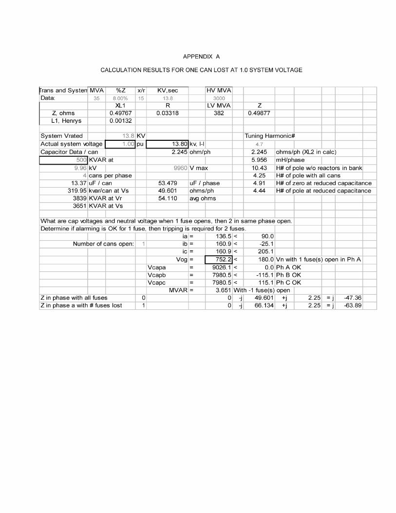
The bank used for examples and calculations in thispaper is a tuned bank made up of four cans per phaserated at 500 KVAR at 9960 volts. The reactors in eachphase are 5.956 mH. At typical line to neutral voltage in a13.8kV system the cans produce 319.95 KVAR each. Thetotal bank is 4022 KVAR. Note that this is more than 12 x319.95 due to the effect of the voltage rise in the reactors inthe bank. The bank is connected as an ungrounded wye.
The detection of abnormal conditions inside a bank isusually accomplished using data collected outside of abank. To do this the abnormal conditions must beidentified, and then the external currents and voltagesassociated with each condition must be calculated.Methods are described in C37.99 involving internalsensors, but this drives up the cost and complexity of thebank. Schemes with numerous internal sensors are nottypically usually used in small industrial banks.
One method for determining external voltages andcurrents for various failure conditions is to use charts inANSI C37.99. The C37.99 methods appear to providemagnitudes of currents and voltages, but not the angles.There is also no way to help you feel confident of themagnitude values derived from counting components andusing a formula for a particular connection. If you choosethe wrong formula, or count the wrong components, youmay get results that are wrong, and you have no way tocheck them. also do not know if the C37.99 methods canbe used at all to determine currents and voltages whencans are lost in different phases. Rather than taking timeto understand the C37.99 methods, found it to be fareasier to simply solve the currents and voltages as anunbalanced three phase system problem.
In the discussions of various protection schemes thatfollow, normal system voltage of 13,800 volts is assumed.The effects of abnormal system voltage from 95% to 110%of normal are discussed separately after the differentschemes are described.
The first step in the solution of the unbalanced threephase circuit problem is to define the current and voltagephase vectors. The vector quantities that represent the
1-4244-1 192-0/07/$25.00 C2007 IEEE.
bank, and a circuit diagram defining the circulatingcurrents, are as shown in Figure 1. Note that the circuitdiagram in Figure 1 is not a "vector" diagram, and thephases are not shown in a counter clockwise rotation. Thephases are shown as they are to make a neat presentationof Vab and Vbc. Also note that ii and i2 are defined in thecircuit diagram as currents circulating in the system. Theseare not positive and negative sequence components, justcurrents assigned to be flowing in the loops. This is part ofthe procedure for solving the unbalanced three phasesystem problem.
FIGURE 1PHASOR AND CIRCUIT DIAGRAMS
Vcg
Vca ia is at 90 degreesVectors rotate ib is at -30 degrees
Counter-ClockwiseVbc ia
\| Vagof~~~~~~~ g
Vab
Vbg
a ia -
Vab Za
1 4- Zb cb ib -*-/-
IcVbc ic -i2 4
The currents i1 and i2 can be determined usingsimultaneous equations. Then i1 and i2 can be used todetermine phase currents ia, ib, and ic. Phase and neutralvoltages, and negative sequence components can all becalculated using these phase currents. For the case of theloss of one can in phase A of the typical bank all of thephase currents and voltages, for normal system voltage,are listed in Appendix A. The voltages and currents forsystem voltages ranging from 90% to 105% voltage, fornormal operation and for operation with one or two canslost are shown in Appendix B.
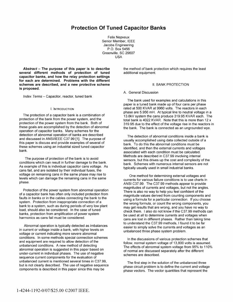
B. Protection Scheme 1, Split-Wye
is used in the link between the neutrals of the two sides ofthe bank. The CT must be rated or installed in a mannerthat provides protection from full system voltage. Wiring isrequired from the CT to a relay.
FIGURE 2SPLIT-WYE BANK
Al_C,A2 r-) A3CiA4 Ph,,, A
The current in the CT in the neutral jumper is used todetect the loss of a capacitor can. The currents in eachphase are first determined by the three phase solution forthe unbalanced condition being examined. These phasecurrents are then split between the cans in each phase todetermine the neutral jumper current. An example of this isshown in Appendix C. In the example for this paper thecurrent in the neutral jumper is 22.8 amps for one can lostin any phase, and 49.5 amps for two cans lost in the samephase on the same side of the bank.
The second can that fails will probably be in the samephase as the first can that failed since can voltage in thisphase rises from 8345 volts to 9026 volts. The canvoltages in the other two phases both drop to 7981 volts.But then there are three cans left in the phase with thefailed can, one on the same side as the first can that failed,and two on the other side. All three have an equal chanceof failure. It is more likely that the second can that fails willbe on the other side of the bank since there are two on thatside. In this case the neutral current between the sides ofthe bank returns to zero, and there is no trip because eventhe alarm condition is lost. If the split-wye scheme is usedalone the bank should be tripped on the loss of the firstcan.
Although unlikely, if the second can that fails is on thesame side of a bank, but in a different phase, the neutralcurrent stays approximately the same. The neutral currentis 22.8 amps for one failed can, and rises to only 25.1amps if a second can fails in a different phase on the sameside. Some relays have sufficient accuracy to discriminatebetween these two levels, but some may not. This isanother reason that the split-wye bank should be trippedupon the loss of the first can.
Probably the most popular scheme discussed in ANSIC37.99 involves splitting the bank in two sections andmonitoring current flow between the neutral points of eachside. This is typically called a split-wye bank. Each side ofa split-wye bank must have the same amount ofcapacitance in each phase. But note that the two sides donot have to be equal in capacitance. There can be twocans per phase on one side and three cans per phase inthe second side, as long as each side has an equal amountof capacitance in each phase. A current transformer, CT,
C. Protection Scheme 2, Neutral to Ground Voltage
If a bank is built as a single ungrounded wye unit, thevoltage from the neutral of the bank to ground can bemonitored to determine the loss of one or more capacitorcans. A potential transformer, PT, is required, typically14400/120V for a 13.8KV system, and it is connected fromthe neutral of the bank to ground. The PT primary must berated for full system voltage. Wiring from the PT to a relayis needed.
The same initial calculation is needed in this scheme asis needed for the split-wye scheme to determine all thephase currents. Then the phase currents and impedancesare used to calculate the voltage drop from each phase toneutral, then from neutral to ground. It is good if thecalculations for all three phases yield the same answer forneutral to ground voltage. The voltage from neutral toground is 752 volts for one can lost in any phase, and 1638for two cans lost in the same phase.
If a second can fails in a different phase the neutral toground voltage shifts from 752 volts to 831 volts. A settingbetween 752 and 831 volts should be able to detect asecond can failing, in the same or a different phase. Thereis about the same difference in voltage in this scheme asthere is difference in current in the split-wye neutral currentsensing method for the loss of a can in a different phase.
D. Protection Scheme 3, Negative Sequence Current
Another scheme that can be used to detect the loss of acan in a bank built as a single unit is to monitor negativesequence current, 12. No CTs or PTs are required in thebank. The phase CTs in the breaker protecting the bankagainst overcurrent provide the data required for measuring12. A protection relay that can monitor 12 is required. Theseare now common and are not expensive. No additionalcurrent circuit wiring is needed when a multifunction relay isused that incorporates negative sequence and overcurrent.
The same initial calculation is needed for this scheme asfor the split-wye bank and the VNG sensing scheme todetermine all the phase currents. An additional step is thenneeded to calculate the negative sequence component ofthe three unbalanced phase currents. This is done usingthe formulas for sequence components as shown inAppendix D. The calculated negative sequence current isthen used as the basis of the relay setting.
The 12 current for a single can failed is 15.9 amps. The 12current for two cans lost in the same phase is 34.6 amps.The 12 current for two cans lost, but in different phases, is13.0 amps. The 12 current scheme can not be used todetect a second can lost in a different phase. But thenagain, the most likely second can to fail will be in the samephase.
E. Loss of Cans in All Three Phases
One further situation to consider is the equal loss ofcapacitance in all three phases. This is an unlikelysituation, but a positive method of detection of this situationwould add to the security of the protection scheme. Asmentioned earlier this results in significant loss of VARsand a significant rise in the tuning frequency of the bank.The voltage and 12 schemes will not detect this at all. Thesplit-wye scheme will detect this situation only if the cansfail on different sides of the bank.
F. Protection Scheme 4, Bank Current
No matter how cans are lost bank current will bereduced. Protection based on bank current could be set upas an under-current tripping scheme. In some casesindividual phases would be monitored. In other casesaverage current can be monitored, but most of the olderdigital relays do not compute an average of phase currents.The current in a phase with an isolated can will drop from168.2 amps to 136.5 amps. The current in the other twophases will be 160.9 amps, so an under-current trip settingbetween 160.9 and 136.5 should indicate a lost can. Forthe loss of two cans in the same phase the current drops to99.1 amps, while the current in the other phases drop to153.9 amps. A current in one phase below 136.5 ampsindicates the loss of at least two cans in a single phase.For two cans lost in different phases the current drops to131.7 amps in those two phases. So, current between136.5 amps and 131.7 amps in two phases indicates thattwo cans are lost.
The reduction of current scheme of bank protection maybe the easiest and the most secure method of bankprotection, with the least additional equipment and wiringrequirements. It involves only the unbalanced systemcurrent calculations. It also works for both plain capacitorbanks and tuned banks. It will probably not work for largebanks with many series and parallel connected cans sincethe loss of a few cans will make little difference in totalbank current output. This scheme is not discussed in ANSIC37.99, but probably deserves consideration.
G. The System Voltage Problem
The difficulty with all of these schemes is that bankcurrents and voltages vary with system voltage. AppendixA shows bank currents and voltages for various conditionsat 0.9, 0.95, 1.0, and 1.05 system voltage. It can be seenthat settings for the various schemes that work at 1.05times normal system voltage may not work for 0.95 timessystem voltage. Trying to find just the right setting thatworks for a reasonable voltage range is possible, but then itmay trip improperly under extreme voltage conditions whenthe bank is really needed.
A means of solving this voltage problem is to have acurrent trip function that varies with voltage, such as the51V function. Even the latest versions of several digitalrelays now available do not appear to have trip functionsthat respond to variable set-points. This could possibly bedone with the logic capabilities of several new relays, but itwould be difficult. A definite time current trip function thatcan be controlled by system voltage could become thefunction of choice for capacitor bank protection. Thisfunction, with time delays, could easily accommodatesystem swings and transients. And then, for free, theadvantages of the data collection, communication, andalarm capabilities of the modern digital relays will also beavailable.
H. Other Bank Protection Schemes
There are additional differential current schemes in ANSIC37.99 that require multiple CTs, relays, and much wiring.These are not usually found in small industrial banks. Theyare normally used in large utility banks with many seriesand parallel cans in each phase.
I. Protection After System Shutdowns
There are many horror stories of over-voltage incidentsoccurring when power systems are re-energized after ashutdown with capacitor banks still connected [2]. Whenthe plant is energized there is no real or reactive load. Butthe capacitor bank which was left connected produces thefull rated VAR output. The VARs have to go somewhere.The VAR flow from the bank to the utility causes a voltagerise on the plant side of the utility tie transformer. Avaluable, and easy to implement, protective function issimply a trip of all capacitor banks if system voltage dropsto zero for a period of time. The time to trip may need to bebased on utility re-closing practices, or re-closing practicesmay need to be re-evaluated.
Re-closing of the capacitor bank breaker can also beblocked by various system voltage or utility load criteria. Apotential transformer is needed to sense system voltage forthis function, but it will probably already be available in anysystem. A voltage relay is also needed, but this functionwill probably also be available in any multifunction relaytypically used.
Ill. CONCLUSIONS
All of the protection schemes for capacitor banks requiresettings for protective devices. The calculations for all ofthe schemes usually start with the determination of phasecurrents in the bank a particular failure condition. Phasecurrents may then be used to calculate voltages andnegative sequence components as needed. Examples of
calculations of neutral jumper current and negativesequence current components are included in this paper.
The typical protection schemes can be blinded byabnormal "abnormal" conditions, such as the loss of cans indifferent phases or on opposite sides of banks. Severalschemes may need to be implemented so that each cancover blind spots of other schemes.
Current and voltage levels used in the different schemesvary with system voltage. Settings based on normalsystem voltage may not function properly over the fullrange of typical system voltages.
A new scheme is suggested in this paper for thedetection of abnormal operation of a bank based on under-current, with set-points that vary with system voltage.
It is also hoped that protective relay setup programscould include the calculations of setting levels for thedifferent schemes based on definition of the components ina bank.
IV. REFERENCES
[1] ANSI/IEEE C37.99-2000, IEEE Guide for theProtection OF Shunt Capacitor Banks, New York, NY:IEEE.
[2] Ronald M. Simpson, "Misapplication of PowerCapacitors in Distribution Systems With Non-LinearLoads - Three Case Histories", Conference Record of2004 Annual Pulp and Paper Industrial TechnicalConference, Victoria, British Columbia, Canada, June27 - July 1, 2004, pages 156 - 166
[3] W. D. Stevenson, Jr., Elements of Power SystemAnalysis, New York, N.Y.: McGraw-Hill BookCompany, Inc. 1962, pages 272-278
APPENDIX A
CALCULATION RESULTS FOR ONE CAN LOST AT 1.0 SYSTEM VOLTAGE
rrans and Systerr MVAData: 35
Z, ohmsLI, Henrys
%Z x/r KV,sec
XL10.497670.00132
R0.03318
System Vrated 13.8 KVActual system voltage I 1.00 p 13.801 kv, I-I
Capacitor Data / can 2.245 ohm/ph5001 KVAR at9.96kV 9960V max
4 cans per phase13.37 uF / can
319.95 kvar/can at Vs3839 KVAR at Vr3651 KVAR at Vs
53.47949.60154.110
Tuning Harmonic#
2.2455.95610.434.254.914.44
uF / phaseohms/phavg ohms
ohms/ph (XL2 in calc)mH/phaseH# of pole w/o reactors in bankH# of pole with all cans
H# of zero at reduced capacitanceH# of pole at reduced capacitance
What are cap voltages and neutral voltage when 1 fuse opens, then 2 in same phase open.
Determine if alarming is OK for 1 fuse, then tripping is required for 2 fuses.ia = 136.5 < 90.0
Number of cans open: 1 ib = 160.9 < -25.1ic = 160.9 < 205.1
Vog = 752.21 < 180.0 Vn with 1 fuse(s) open in Ph AVcapa - 9026.1 < 0.0 Ph A OKVcapb = 7980.5 < -115.1 Ph B OKVcapc = 7980.5< 115.1 PhCOK
MVAR - 3.651 With -1 fuse(s) open
Z in phase with all fuses 0 0 i 49.601 +j 2.25 = j -47.36Z in phase a with # fuses lost 1 0 i 66.134 +j 2.25 = j -63.89
HV MVA
LV MVA382
z0.49877
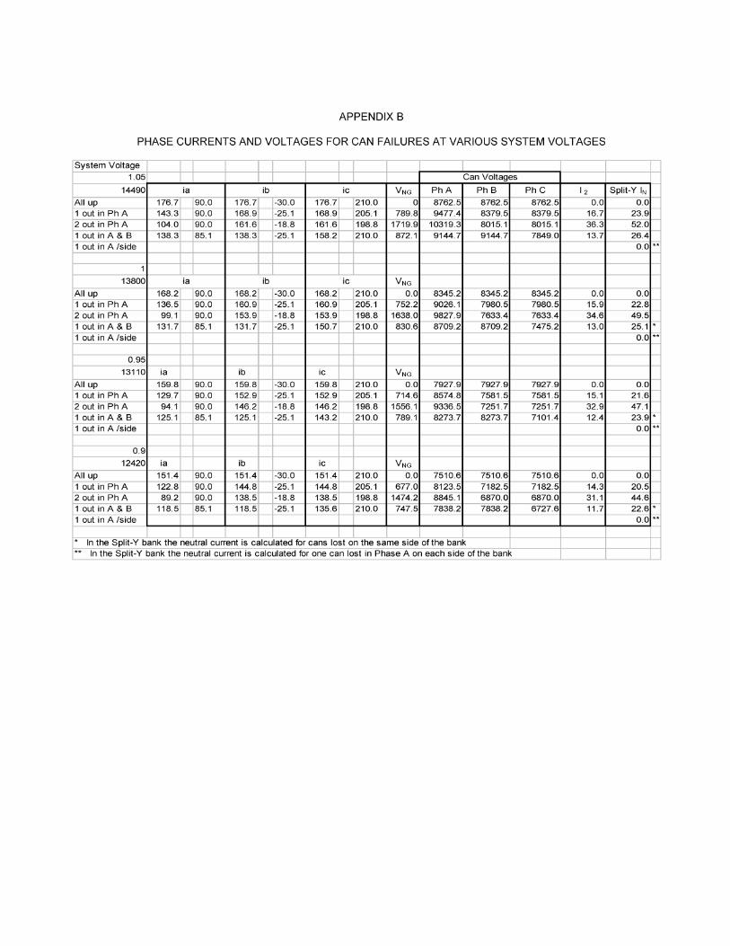
APPENDIX B
PHASE CURRENTS AND VOLTAGES FOR CAN FAILURES AT VARIOUS SYSTEM VOLTAGES
System Voltage1.05
14490All up1 out in Ph A2 out in Ph A1 out in A& B1 out in A /side
113800
All up1 out in Ph A2 out in Ph A1 out in A & B1 out in A /side
0.9513110
All up1 out in Ph A2 out in Ph A1 out in A& B1 out in A /side
0.912420
All up1 out in Ph A2 out in Ph A1 out in A& B1 out in A /side
ia176.7 90.0143.3 90.0104.0 90.0138.3 85.1
ia168.2136.599.1131.7
ia159.8129.794.1
125.1
ia151.4122.889.2
118.5
90.090.090.085.1
90.090.090.085.1
90.090.090.085.1
ib176.7 -30.0168.9 -25.1161.6 -18.8138.3 -25.1
ib168.2 -30.0160.9 -25.1153.9 -18.8131.7 -25.1
ib159.8152.9146.2125.1
ib151.4144.8138.5118.5
-30.0-25.1-18.8-25.1
-30.0-25.1-18.8-25.1
ic176.7 210.0168.9 205.1161.6 198.8158.2 210.0
ic168.2 210.0160.9 205.1153.9 198.8150.7 210.0
ic
159.8152.9146.2143.2
ic
151.4144.8138.5135.6
210.0205.1198.8210.0
210.0205.1198.8210.0
Can VoltagesI .II I II
VNGO
789.81719.9872.1
VNG0.0
752.21638.0830.6
VNG0.0
714.61556.1789.1
VNG0.0
677.01474.2747.5
Ph A8762.59477.410319.39144.7
8345.29026.19827.98709.2
7927.98574.89336.58273.7
7510.68123.58845.17838.2
Ph B8762.58379.58015.19144.7
8345.27980.57633.48709.2
7927.97581.57251.78273.7
7510.67182.56870.C7838.2
Ph C8762.58379.58015.17849.0
8345.27980.57633.47475.2
7927.97581.57251.77101.4
7510.67182.56870.06727.6
20.0
16.736.313.7
0.015.934.613.0
0.015.132.912.4
0.014.331.111.7
Split-Y IN0.0
23.952.026.40.0
0.022.849.525.10.0
0.021.647.123.90.0
0.020.544.622.60.0
* In the Split-Y bank the neutral current is calculated for cans lost on the same side of the bankIn the Split-Y bank the neutral current is calculated for one can lost in Phase A on each side of the bank
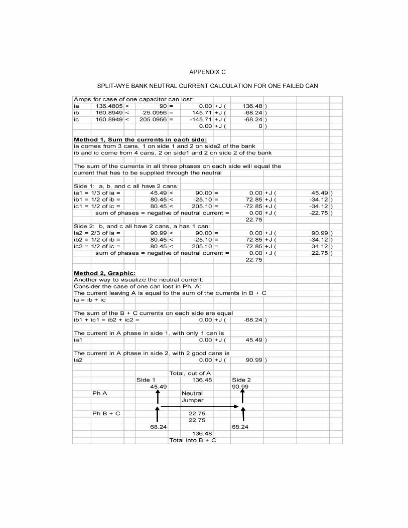
APPENDIX C
SPLIT-WYE BANK NEUTRAL CURRENT CALCULATION FOR ONE FAILED CAN
Amps for case of one capacitor can lost:ia 136.4805 < 90 = 0.00 +J ( 136.48)ib 160.8949 < -25.0956 = 145.71 +J ( -68.24)ic 160.8949 < 205.0956 = -145.71 +J ( -68.24)
0.00+J( 0)
Method 1, Sum the currents in each side:ia comes from 3 cans, 1 on side 1 and 2 on side2 of the bankib and ic come from 4 cans, 2 on sidel and 2 on side 2 of the bank
The sum of the currents in all three phases on each side will equal thecurrent that has to be supplied through the neutral
Side 1: a, b, and c all have 2 cans:ial = 1/3 of ia = 45.49 < 90.00 = 0.00 +J ( 45.49)ibl = 1/2 of ib= 80.45 < -25.10 = 72.85 J -34.12)icl = 1/2 of ic = 80.45 < 205.10 = -72.85 +J ( -34.12
sum of phases = negative of neutral current - 0.00 +J ( -22.7522.75
Side 2: b, and c all have 2 cans, a has 1 can:ia2 = 2/3 of ia = 90.99 < 90.00 = 0.00 +J( 90.99)ib2= 1/2 of ib= 80.45 < -25.10 = 72.85 J -34.12)ic2- 1/2 of ic 80.45 < 205.10 = -72.85 +J( -34.12)
sum of phases = negative of neutral current = 0.00 +J ( 22.75)22.75
Method 2. Graphic:Another way to visualize the neutral current:Consider the case of one can lost in Ph. A:The current leaving A is equal to the sum of the currents in B + Cia = ib + ic
The sum of the B + C currents on each side are equalibl + icl = ib2 + ic2 = 0.00 +J ( -68.24)
The current in A phase in side 1, with only 1 can isial 0.00 +J 45.49
The current in A phase in side 2, with 2 good cans isia2 0.00 +J ( 90.99)
Total, out of ASide 1 136.48 Side 2
45.49 90.99Ph A Neutral
Jumper
PhB+ C 2275 f22.75
68.24 68.24136.48
Total into B + C
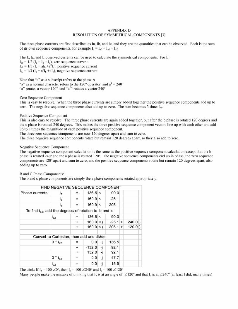
APPENDIX DRESOLUTION OF SYMMETRICAL COMPONENTS [3]
The three phase currents are first described as Ia, Ib, and Ic, and they are the quantities that can be observed. Each is the sumof its own sequence components, for example 'a = laO + 'al + Ia2
The 'a, lb, and I observed currents can be used to calculate the symmetrical components. For a:'aO = 1/3 (Ia + lb + I'), zero sequence current'al = 1/3 (Ia + alb +a2I1), positive sequence currentIa2= 1/3 (la + a2lb +alc), negative sequence current
Note that "a" as a subscript refers to the phase A"all as a normal character refers to the 1200 operator, and a2 2400"a" rotates a vector 1200, and "a2" rotates a vector 2400
Zero Sequence ComponentThis is easy to resolve. When the three phase currents are simply added together the positive sequence components add up tozero. The negative sequence components also add up to zero. The sum becomes 3 times 10.
Positive Sequence ComponentThis is also easy to resolve. The three phase currents are again added together, but after the b phase is rotated 120 degrees andthe c phase is rotated 240 degrees. This makes the three positive sequence component vectors line up with each other and addup to 3 times the magnitude of each positive sequence component.The three zero sequence components are now 120 degrees apart and sum to zero.The three negative sequence components rotate but remain 120 degrees apart, so they also add to zero.
Negative Sequence ComponentThe negative sequence component calculation is the same as the positive sequence component calculation except that the bphase is rotated 2400 and the a phase is rotated 1200. The negative sequence components end up in phase, the zero sequencecomponents are 1200 apart and sum to zero, and the positive sequence components rotate but remain 120 degrees apart, alsoadding up to zero.
B and C Phase Components:The b and c phase components are simply the a phase components rotated appropriately.
FIND NEGATIVE SEQUENCE COMPONENTPhase currents: la 136.5 < 90.0
ib = 160.9 < -25.1
ic = 160.9 < 205.1To find ia2, add the degrees of rotation to lb and Ic
la2 1 36.5 < 90.0+ 160.9 <( -25.1 + 240.0)+ 160.9 <( 205.1 + 120.0)
Convert to Cartesian, then add and di\nde:3 ia2 = 0.0 +j 136.5
+ -132.0 i 92.1+ 132.0 i 92.1
3 ia2 = 0.0 -j 47.7
la2 = 0.0 -j 15.9The trick: If 'a 100 /0z, then lb 100 /2400 and Ic 100 Z1200Many people make the mistake of thinking that lb is at an angle of Z1200 and that Ic is at Z2400 (at least I did, many times)