Embed Size (px)
Citation preview

Engineering and Scientific International Journal (ESIJ) ISSN 2394-187(Online)
Volume 2, Issue 2, April - June 2015 ISSN 2394-7179 (Print)
23
Medium Voltage Capacitor Banks Characterization and Transients
Generated S.G.Mohammad
#1, C.Gomes*
2, M.Z.A AbKadir*
3, Jasronita.Jasni*
4, M. Izadi*
5
Centre for Electromagnetic and Lightning Protection Research (CELP), Universiti Putra Malaysia, 43300 Serdang, Malaysia
Abstract— This review presents an analysis of the over
voltage electromagnetic transient’s phenomena during an
energizing and de-energizing of capacitor banks. The
investigation has been extended to non-linear loads and
distributed power systems in medium voltage electrical
system. In addition, sensitive analyses of characterization
impact factors have been discussed. Effects of switching
transients of the capacitor bank on the regression of power
quality in distribution systems have been analyzed and the
results are presented in detail. The outcome of this study
provides practically significant information for the power
engineers that design electrical networks for medium
voltage distribution systems.
Keywords— Capacitor banks, Transients’ overvoltage,
Electrical grid switching.
1. Introduction
Capacitor banks are by and large utilized as a part of
both distribution and lower sub-transmission levels, to
boost system capacity, decrease power losses, and enhance
voltage conditions and performance of transformers at
different parts in the grid. However, in spite of all
important features of connecting capacitors in the field,
they can also contribute to power quality problems. The
switching process to energize and de-energize these
capacitor banks happen often because of the system load
variation or voltage fluctuation. These switching operations
lead to transient overvoltage, which may damage the
switching appliance identified as striking or re-striking of
the switching device. The energizing of the capacitor bank
causes elevated inrush current and transient voltage
oscillation at the capacitor bank station [1]. Generally, the
declines in service power, cost and release of system
capacity are the major motivators, with loss reduction and
upgrading of voltage level stability being additional
benefits of lesser importance. with the trend towards a
higher cost of electric power bills increased cost, and
lowering of system capacity, it is expected that there will
be many more opportunities for capacitor applications at
the medium voltage level [2] in the future. in low voltage
lv systems, capacitor banks may reduce and totally prevent
power factor penalties [3]. Transients are microsecond to
lower order millisecond scale fluctuations, in the steady
condition voltage or current waveform. There is no obvious
similarity between transients and dip or swells, though, for
the plurality's fraction discussion, any occasion with a term
less than half a cycle is apparently a transient [4]. in this
paper, we present the issues brought out by capacitor banks
during the switching operations, and characterize the
transients generated.
2. Information Analysis
2.1 Capacitor units
2.1.1 Ceramic capacitors
Ceramic capacitors are obtainable in three modules
confer to a dielectric constant and temperature rendering
[5]. They are used in a peak frequency circuit, for example,
radio frequency RF, and selection for rising frequency
indemnification in an auditory circuit. Ceramic dielectric,
solid or multilayer’s, structure – lowest level inductance,
and low equivalent series resistance (ESR), height voltage
(10.0-kilo volt), doorknob capacitor, are available based on
dielectric constant, temperature stability. Arrangements of
class are as follows:
2.1.1.1 NPO/ COG
They are good in temperature stability [6],with positive
and negative temperature coefficients, widely available,
ultra steady having a low dielectric constant, costly and
large
2.1.1.2 X7R/Y5R
They are reasonable size, having nonlinear variation with
temperature, have 20 to 70 times as much capacitance per
case size; however, the capacitance typically
2.1.1.3 Z5u/Y5u
They exceed five times the capacitance of Class two and
have undomesticated swings of capacitance with voltage
and temperature. The temperature varies from –25 °C to
85 °C. and capacitance change between +20% and -65%
[5].
2.1.2 Film capacitors
Encompass polyester, polypropylene, polycarbonate and
others. Each has its own strengths and weakness. These are

Engineering and Scientific International Journal (ESIJ) ISSN 2394-187(Online)
Volume 2, Issue 2, April - June 2015 ISSN 2394-7179 (Print)
24
normally used filters; equalizers and power supply bypass
duty.
2.1.2.1 Films
Plastic film dielectric is often tubular construction and
high series inductance. Polypropylene: good overall
specifications, low upper temperature range of Range
available 0.5Pf – 0.1µF. Operating frequency ˂10 MHz
Rp˃ min (1000, 000 MΩµF, 1000, 000MΩ) [7]. The film
possessions are indicative of the way that material
developers are taking to create new production of plastic
film [8].
2.1.3 Electrolytic
Electrolytic capacitors apply aluminum foil[9]. Metal
oxide film on metal electrode and small-sized electrolyte
electrode, small size. Mostly polarized and non-polarized
version has half the capacitance poor temperature
coefficient, and low frequency. Aluminum electrolytic
capacitors used in the direct current (dc) link of
regenerative Induction Motors IM drives. The dc-link
capacitance was varied from 200 μF to 12000 μF and the
source inductance from 1 mH to 5 mH for ambient
temperatures of 25 °C, 40 °C and 85 °C the evaluation of
the results confirmed that the lifetime of the capacitor
considerably decreases while they work at elevated
ambient temperatures [10].
2.1.3.1. Aluminum
Is good overall specification, low upper temperature
range of higher ESR and leakage current than tantalum
range available 0.1 to 2μF. Operating frequency ˂ 10 MHz,
Rp ˃min 5MΩ[11].
2.1.3.2 Tantalum
It has better characteristics than electrolytic but still
small for high capacity values. Stable low upper
temperature range of high cost; tantalum is rare metal low
voltage application, low dielectric constant, large size, high
Q, low series resistance high resistance to corrosion, less
temperature sensitive than aluminum, more expensive than
aluminum, more reliable for time than aluminum.
2.1.3.3 Silver Mica Capacitors
Silver Mica Capacitors is one of the best types of
capacitors. Mica, a mineral, is one of the oldest dielectric
materials used in capacitor building. There are numerous
sorts of mica with differing properties, but mica is in
common extremely steady electrically, mechanically, and
chemically [8,12]. Mica capacitors, typically silver mica,
have been highly reliable since mica has higher quality
dielectric with excellent discharge resistance.
2.1.3.4 The super-capacitor (SC)
It is a very attractive storage device for working as a
supplementary source of FC power. It presents very fast
dynamics and can store more energy than conventional
capacitors[13].
2.2 Types of power capacitor banks
Capacitor's power banks are particularly capable
particular in four appearances, as follows: 1. Metal-
Enclosed, 2. Pad-Mounted, 3. Stack-Rack 4. Pole-Top all
of which are High-voltage shunt capacitor banks:
2.3. Request of power capacitors
A capacitor draws leading current. When linked to an
inductive circuit, it offsets its inductive (reactive)
component and develops the power factor of the circuit. It
can be applied and accordingly categorized in two ways as
follows:
The Shunt capacitor –associated across the inductive
circuit to develop its power factor.
The Series capacitor –linked in series at the remote end
to the length of transmission or all voltages of 2.4 kV. It
is also on top of a high-voltage system, to recompense
the reactive elements of the line impedance which
includes the voltage decline and enhance the receiving
end voltage.
2. 4. Ambient Temperature
For all time, capacitors are designed for switched or
continuous operation in outdoor locations, with unrestricted
ventilation and direct sun light. Under ambient
temperatures, they are designed for mounting arrangements
as shown in table (1). Capacitors are designed for
continuous operation at - 40°C, and operation of capacitor
banks within ambient temperature increases the life time
work of the capacitor bank in the field, in addition to
saving the continuity of power supply to the consumers.
Nevertheless, it spares the congruity of power supply to the
buyers [2]. Capacitors are appropriate for operation at their
particular rating. When the ambient temperature is
surrounded by limited rating, the height does not exceed
1800meters. Above sea level, the voltage applied between
terminals does not exceed the rating voltage by more than
the accepted rate, and the applied voltage does not contain
harmonics as well as rating frequency equal to the rating
source frequency [5]. If the capacitor is needed to operate
in harsh environment (such as dust, fumes or vapours,
under mechanical shock or vibration, high radiated
Engineering and Scientific International Journal (ESIJ) ISSN 2394-187(Online)
Volume 2, Issue 2, April - June 2015 ISSN 2394-7179 (Print)
25
temperature from surfaces, altitude higher than 1800 meter
above sea level ), the appliance request should be brought
to the awareness of the manufacturer [5]. If the capacitor is
essential to work on the earth, (for example, dust, exhaust
or vapors, under mechanical stun or vibration, high
emanated temperature from surfaces, height higher than
1800 meters below an ocean level ), the apparatus demands
ought to be carried to the consciousness of the producer. [6]
as displayed in table (1) below[2].
Table 1: Maximum ambient temperature,[2]
(i) Capacitor must be tolerant to, voltage and current rating
in over-load consistent with standard IEEE std.18 -2002,
IEEE std.1036-1992.It should also aid in the requisition of
shunt power capacitors [6]. IEEE Std. 18 -1980 give the
impediments of capacitor operation at or beneath, are
anticipated crises and not planned for ordinary operation.
(ii) 110% of rated rms voltage. (iii) 120% of rated crest
voltage, (iv) 135% of rated rms current (nominal current
dependent upon kvars and voltage), (iv) 135 % of rated
kvars. Capacitor might be too appropriate for steady
process at up to 135% of appraised reactive power as a
result of unified consequence of:
(a) Voltage in over loads of nameplate rating at essential
frequency, (b) Harmonic's voltages superimposed on the
basic recurrence, and(c) reactive power manufacturing
acceptance of up to 115%of appraised reactive power [7].
2. 5 Capacitor Banks
Most of the power system loads equipment are inductive
in nature and thus run at a lagging power factor. When
system in service at a lagging power factor the power
system need extra (var) flow, with reduced system capacity,
increased system losses and reduced system voltage,
implementation of shunt capacitor banks in the system
increase system capacity, reduce system losses,(vars)
support, voltage control and reduce billing charges.
Summary of benefits of applying shunt power capacitors
are divided in to two categories, namely: primary and
secondary compensation. Distribution and transmission
lines (examples: voltage controls, increase system capacity,
reduces system power losses, and reduce billing charges),
are generally considered primary benefits, while var
support was secondary. In transmission system var support
and voltage control are generally a primary benefits while
increasing of system capacity and system losses are
secondary benefits. The subsequent method can be used to
calculate approximately voltage rise that capacitor will
create [5]. The resulting strategy might be utilized to figure
roughly voltage climb that capacitor will make
[5]:
2
10
var
kv
XkV
L
rise
(1)
∆Vrise is the percentage voltage increase by the tip of the
capacitor fitting; kV is the scheme line –to line voltage
without capacitor in service. kvar is the three phase kilovar
rating of the bank. XL is the inductive reactance of the
system at the point of the capacitor installation in ohms.
The most favorable economic power factor for system,
with consideration, to released capacity only, can be
evaluated by using of the following rule[5]:
2
.1
i
i
opt
S
CPF
(2)
Where Ci is expense per kilovar of capacitor banks, Si is
the expense per kilovolt amperes of scheme tools; PFopt is
most favorable power factor.
2.6 Capacitor in Distribution Networks
Commonly, capacitors utilized in distribution systems are
situated on the distribution lines or in substations. This
article expounds on the way through which capacitors are
positioned on distribution lines, which may be in pole-
mounted racks, pad–mounted banks or submersible
installations. The distribution capacitor banks frequently
comprise of three to nine capacitor units. These units are
installed in three phases which are: grounded–wye,
ungrounded– wye, or delta arrangement. Seeing that they
are closer to the load, capacitors located on the distribution
lines stand for a further effectual resource for supplying the
reactive power necessities which simultaneously
minimizes system losses., distribution line capacitor banks
are either switched or fixed. Normally, in determining the
kinds of the bank necessary strategies such as fixed
capacitor banks are sized for minimum load conditions,
while switched capacitor banks are contagious for load
levels above the minimum condition. Up to crest load,
capacitors found in the distribution lines stand for further
effective assets for supplying the reactive power necessities
in the meantime as minimizing framework losses.
Distribution line capacitor banks are either exchange or
permanent. Typically, in figuring out the sorts of bank
Capacitors Ambient air temperature
c
Mounting arrangement 24h average Normal annual
Isolated capacitor 46 35
Single row of capacitors 46 35
Multiple rows and tiers of
capacitor 40 25
Metal–enclosed or housed
equipment 40 25

Engineering and Scientific International Journal (ESIJ) ISSN 2394-187(Online)
Volume 2, Issue 2, April - June 2015 ISSN 2394-7179 (Print)
26
essential for accompanying procedure, settled capacitor
banks are measured for least load conditions, while
switched capacitor banks are infectious for load levels
above the base condition up to peak load [2]. The curve
representing in Figure (1) summarized a characteristic’s
kilovar request over the 24-hour period. The fixed banks
fulfill the base load requests, and the exchanged banks
adjust for the inductive kilovar crest all around, the
intensive load duration figure (1) [2]
Fig.1: Switching Capacitors
2. 6.1 Sizing and location of capacitor banks
Different techniques have been planned to conclude the
relative location of switched capacitors. Capacitor banks
must be accurately sized to drive properly. If the capacitors
are energized, at all time or fixed, care must be taken not to
oversize it. If the reactive power is furnished by the
capacitor exceeds the reactive power demand of the load,
the power factor will be higher, which can cause poor
voltage regulation resulting in high voltage during the
period of light load. To avoid such leading power factors,
the capacitor should be sized such that power factor does
not exceed unity even when a programmed percentage of
the connected load is not energized. This percentage varies
with the expected diversity of the load. Therefore, a good
understanding of the load characteristics is necessary for
proper capacitor sizing[14]. If the purpose to reduce losses,
capacitors will be coordinated with and positioned
neighboring to sources of lagging vars [15]. In systematize,
quite a lot of pieces of information are required to compute
the necessary amount of capacitance and increase the
present system power factor with particular higher power
factor. In KVA or kW and power factor of the standing
load, the difficulty comes from the fact that we can
compute the power factor in dissimilar ways and these
diverse ways influence much capacitance required to apply
in a given location. A number of utilities calculate power
factor as an average of the duration of fifteen or thirty
minutes interval which is concurrent with the crest kW or
kva demand, depending on how the interest, bills for peak
demand. Other utilities accumulate kilowatt-hours and
kilovars hours over the course of the month. In the previous
container, one would use the power factor and the peak kW
or kva during the demand interval as the requisite of kvar
computation. In conclusion, one would use accumulated
kWh and kvar to first compute the necessary kvars of
correction needed over the month, and then divide out the
hours in the month to get the required capacitor size. The
objective of capacitor placement in the distribution system
is to minimize the annual cost of the system. To maintain a
strategic distance from extremely leading power calculates,
the capacitor ought to be sized, such that the power
component does not surpass unity actually when modified
rate of the joined load is not energized. This rate shifts with
the normal differences of the load. Hence a great
comprehension of the load attributes is important for
legitimate capacitor measuring[16]. When the reactive
interest of a transport differs uncommonly, the capacitor
must be switched. For the term of times of high reactive
interest, the capacitor might be energized, and when the
reactive interest reduces, the capacitor could be de-
energized. In systematize, a considerable amount of data
are needed to figure the important measure of capacitance
and build the current framework power variable with
specific higher power component. The KVA or kW and
power component of the standing load, the challenge hails
from the way that we can process the power figure in
unique ways and these different ways can impact what
amount of capacitance we require to apply in a given area.
Various utilities compute power can be calculated as
normal for the length of time of fifteen or thirty minutes
interim simultaneous with the peak kW or kVA interest,
contingent upon size. The target of capacitor situation in
the distribution framework is to minimize the twelve-
month expense of the grid [17], and to accomplish the most
good point of interest of shunt power capacitor requisition
on the spreading framework The capacitor banks ought to
be spotted where they make the greatest losses diminish,
supply the greatest voltage profits, and are as near the load
as could be expected under the circumstances. While this
is not functional, a few general guidelines have been used
for placing capacitors. These embody the accompanying:
(1) intended for consistently spread loads where the
capacitor ought to be sited 2/3 of the separation starting
from the substation. [18](2) For consistently diminishing
distributed loads, the capacitor ought to be positioned one
half of the separation from substation [18]. (3) Generally
the maximum extreme voltage climb where the capacitor
ought to be placed close to the end of the line[18]. Extra
particularly, capacitor banks are essential at position where
field estimations show a minimal voltage or lower power
element issue. This information could be gotten as
accompanies, by applying voltage estimations for the term
of full-load situation at distinctive focuses on top of the
feeder. The capacitor measuring mathematical statement
was recorded as follows

Engineering and Scientific International Journal (ESIJ) ISSN 2394-187(Online)
Volume 2, Issue 2, April - June 2015 ISSN 2394-7179 (Print)
27
d
AC
(3)
Where, C=capacitance in farads, ε= permittivity of
dielectric (absolute, not relative), A= area of plate
overlap in square meter, and d = distance between plates in
meters.
ε =ε=εοK
Where, εο= Permittivity of free space, εο =8.8562 10-12
F/m, K= dielectric constant of material between plates.
2.6.2 Selection of capacitor
There are many factors that influence the selection of the
capacitor banks in distribution system, these factors include:
precision, stability, percentage of leakage and breakdown
voltage which minimizes temperature with the rate of time.
2.7 Capacitor banks connection
There are five regular capacitor banks connections. The
favorable connection depends upon the most excellent
employment of the standard voltage rating additionally,
preventive relaying practically on each and every one
substation banks are linked in wye. Allocation capacitor
banks, may though be linked, wye or delta. The different
types of connections illustrated are in figure (2), its explain
the different ways of capacitor banks connection in the grid
[19].
Fig.2: Capacitor bank connections [20]
2.7.1 Delta connection banks
Delta joined banks are ordinarily utilized just at load power
system voltage and arranged by a single series assembly
of capacitors estimated between two-line voltage, since
they require two –bushing capacitors with a protected rack.
2.7.2 Grounded Y - connected banks
The Grounded Y capacitor banks are gathered or arranged
in sequences. Paralleled, joined capacitor units for every
stage give a low-impedance path to ground as figure (3)
shows the externally fused capacitor bank unit and ordinary
bank arrangement plans [19].
Element
case
Bushing
Internal discharge device
CAPACITOR UNIT
A B C
External fuse capacitor unit
Capacitor unit series group
Fig.3: Externally –fused capacitor units [20]
2.7.3 Ungrounded Wyes- connected Bank
Ungrounded wye banks do not permit zero sequence
currents, third harmonic currents, or large capacitor
discharge currents during system ground faults. (Phase-to-
phase faults may still occur and will result in large
discharge currents.) The neutral point of the bank, however,
should be insulated for full line voltage because it is
momentarily at phase potential when the bank is switched
or when one capacitor unit fails in a bank configured with a
single group of units or during close-in system ground fault
[7].
2.7.4. Ungrounded Split –Wye
This design is corresponding to ungrounded wye format.
The split–wye link method is widespread because it is
simple to reveal unbalanced at the neutral[20].
2.7.5 Grounded/Ungrounded Wye Merit
Majority of distribution and transmission-stage capacitor
banks are wye linked, whether grounded or ungrounded.
Characteristics of a grounded bank are as follows:
(a) It offers low impedance for lightning surge currents.
(b) It offers a degree of protection from surge voltages.
(c) It diminishes recovery voltages for switching
equipment (Roughly twice normal crest voltage)
(d) It gives a lowest level impedance to be ground for
triple and further harmonic currents.

Engineering and Scientific International Journal (ESIJ) ISSN 2394-187(Online)
Volume 2, Issue 2, April - June 2015 ISSN 2394-7179 (Print)
28
Characteristics of an ungrounded bank are as follows:
(a) It does not provide a path for zero-sequence currents,
triple, and other harmonic currents
(b) It does not provide a path for capacitor discharge
currents during system faults.
(c) It requires the neutral to be insulated to full-line
voltage [21].
(d) It unbalances assurance with a straightforward
uncompensated transfer since any system zero
sequences grouping part influences both wyes equity.
Yet a failed capacitor units show up as unequal in the
neutral.
2.8 Size and number of banks
Capacitor bank's necessities are conclusive by enhancing
the profits for a given position of system prerequisites.
Capacitor principles are frequently assumed as continuous
variables whose expenses are measured as proportional to
capacitor size by past researchers [22] [23]. However,
commercially obtainable capacitors are separate capacities
and tuned in individual steps[24]. Furthermore, the
expenditure of the capacitor is not linearly proportional to
the size. Therefore, if the incessant variable approach is
used to select essential capacitor size, the technique may
not result in best possible clarification and may still lead to
unwanted harmonic resonance state. Many works have
been studies by several researchers on the capacitor in a
balanced distribution system. Few studies has been done
on capacitor placement to the unbalance distribution
system [25, 26]. Distribution substation capacitors are
habitually measured to provide the var need of the load
supplied by the substation transformer bank. The point
when the capacitor bank is energized or de-energized, the
essential system voltage builds or reduces correspondingly,
to have a negligible impact upon purchaser loads. This
voltage change is frequently limited to value in the range of
2% to 3%. The voltage change ∆V in percent can be to
estimate by the following rule [5]:
%100var
%
MVA
MV
(4)
Where
Mvar = the Mara size of the capacitor bank.
MVAsc = the available three –phase short circuit MVA at
the capacitor location.
The base bank size is affected by the accompanying
elements, capacitor bank, unbalanced contemplations, and
fused coordination. The point where a capacitor works to
show a fizzled capacitor, an unbalance condition can
happen that subjects units in the same group to 60 Hz over
voltage. A regular criterion to the farthest point is over
110% voltage with one unit out. This obliges a base
number of units in parallel as is given in table (2). IEEE
Std 18 -1992 show that a capacitor might reasonably be
foreseeable to withstand throughout typical administration
life Table (3) indicates a joint sum of 300 provisions of
power frequency terminal. The terminal over voltage
without a superimposed transient or harmonic presents of
size and spans.[5].
Table 2. Minimum recommended number of units in parallel per
series group to limit on remaining units to 110% with one unit
out.[5]
Number of
series
groups
Grounded
Y. or
Ungrounde
d Y
Split
ungrounde
d
Y
1 - 4 2
2 6 8 7
3 8 9 8
4 9 10 9
5 9 10 10
6 10 10 10
7 10 10 10
8 10 11 10
9 10 11 10
10 10 11 11
11 10 11 11
12 11 11 11
Table 3. Maximum permissible capacitor voltage [5]
Duration Maximum permissible
voltage(multiplying factor to be
applied to rated voltage rms)
6 cycles 2.20
15 cycles 2.00
1 s 1.70
15 s 1.40
1 min 1.3
2.8.1. Bank Configurations
There are three capacitor bank setups which are
grounded wye, ungrounded wye and delta. Delta associated
capacitors are normally only utilized at low voltage 2.4kV
where standard capacitor rating is not reachable for wye
association. To a large extend, wye- joined capacitor
establishments are less perplexing to construct and more
practical. There are specific points of interest related with
grounded against ungrounded capacitor banks. The
favorable contrasting circumstances between grounded-
wye and ungrounded wyes are:
(a) First expense to the bank may be minor as the
unbiased does not need to be separated from ground
at full framework BIL.
Engineering and Scientific International Journal (ESIJ) ISSN 2394-187(Online)
Volume 2, Issue 2, April - June 2015 ISSN 2394-7179 (Print)
29
(b) Capacitor switch recovery voltages are decreased.
(c) Mechanical obligations, for instance, seismic may be
less brutal for the construction. [5]
2.8.2 Installation of shunt capacitor banks
Establishment of shunt capacitor banks might be made
without any purpose of the system, when estimations are
carried out and harmonic's mutilation is known. The
determination of the compensation techniques could be
made as individual compensation capacitor banks which
can be joined straightforwardly to the terminals of
customers. Group's compensation capacitor banks can be
joined to the distribution system that sustains a number of
singular burdens, and central recompense capacitor banks
in substantial establishments where numerous unique loads
work.
2.9 Capacitor banks protection
To ensure convenience of a capacitor bank,
administration requires dependable security which
guarantees least harm to the bank in the event of a
shortcoming. The banks ought to be segregated from the
system before it is sternly harmed or passed to a
shortcoming created within the framework. The outline of
the capacitor bank defensive framework might as well
recreate attention impact of seven crucial conditions:[19].
Over current due to capacitor banks bus faults.
- System surge voltages.
Over currents due to individual capacitor unit failure.
Continuous capacitor unit over voltages.
Discharge current from parallel capacitor units.
6 - Inrush current due to switching.
7- Arc-over within the capacitor rack.
2.9.1 Selection of the capacitor units fused
The essential purposes in selecting a capacitor fused are:
The fuse should be able to withstand steady state and
transient currents in order toavoid spurious fuse
operations.
The fuse must efficiently remove a failed or failing
capacitor unit from service without causing further
damage or disruption to the capacitor and the system.
[27].
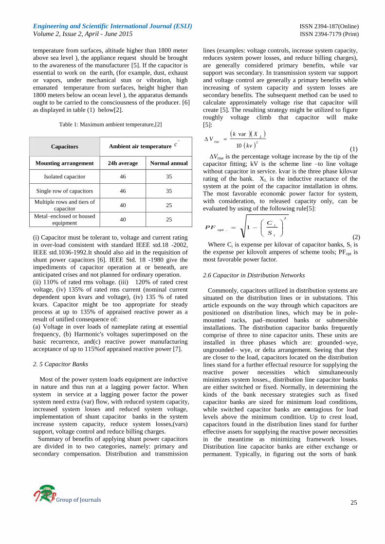
2.9.2 Group fusing
Group fuse can be explained as one fuse prevents more
than one capacitor from damage. As shown in figure below,
commonly employ in pole mounted distribution capacitor
racks.
Fig.4: Group fusing arrangement in wye connected ungrounded
capacitor bank with three capacitor unit per phase.
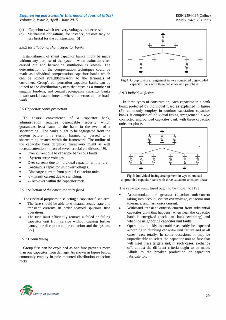
2.9.3 Individual fusing
In these types of construction, each capacitor in a bank
being protected by individual fused as explained in figure
(5), commonly employ in outdoor substation capacitor
banks. It comprise of individual fusing arrangement in wye
connected ungrounded capacitor bank with three capacitor
units per phase.
Fig.5: Individual fusing arrangement in wye connected
ungrounded capacitor bank with three capacitor units per phase.
The capacitor –unit fused ought to be chosen to [19]:
Accommodate the greatest capacitor unit-current
taking into account system overvoltage, capacitor unit
tolerance, and harmonics current.
Withstand transient outrush current from substantial
capacitor units that happens, when near the capacitor
bank is energized (back –to- back switching) and
when the neighboring capacitor unit faults.
Operate as quickly as could reasonably be expected
according to climbing capacitor unit failure and in all
cases react totally. In some occasions, it may be
unpredictable to select the capacitor unit to fuse that
will meet these targets and, in such cases, exchange
offs amidst the different criteria ought to be made.
Allude to the breaker production or capacitors
fabricate for.

Engineering and Scientific International Journal (ESIJ) ISSN 2394-187(Online)
Volume 2, Issue 2, April - June 2015 ISSN 2394-7179 (Print)
30
2.9.4 Capacitor specification items of standard
The following is a synopsis of items that should be
specified by purchase. If the bank is to have to provision
for increased ratings in the future, the purchaser
specification must also comprise meaning of items for
future circumstances in addition to the degree to which
these necessities are to meet in original design and
equipment of the bank. the continuity of capacitors banks
Service require the following conditions , ambient
temperature requirements for outdoor and indoor
equipment, power system frequency, maximum power
system operating voltage, (phase to the grounded insulation
requirements per IEEE or IEC standards, for example, BIL,
switching surge withstood, leakage distance). Rated
reactance of each segment or sub segment, (current rating
for the bank inserted mode, continuous current,
emergency over load current and durations, swing current
and duration) current ratings for the bank bypassed mode,
continuous current, emergency overload current and
durations, swing current and durations, fault current and
durations. Overvoltage protection, types of over voltage
protective device, protection and control and safety.
2.9.5 Bank over current protection
Protecting capacitor bank versus the major fault, such as
a line to line or line to ground fault, in general need a
number of forms of external protection such as power fuse
breakers or circuit switches linked relay circuits., Figure
(4), (a) and (b) show types of over current protection.
Capacitor bank can operate indefinitely at current levels in
excess of that based on rated kvar and voltage. The backup
protection should allow 125% or 135% of rated current to
be carried persistently. [19]. The bank fused design
protection is divided into three categories as follows:
fuseless, internal fused, and external fused., Externally
fused capacitor banks have higher failure voltage and
currents than fuseless or internally fused banks, because an
external fused blowing causes the loss of a whole units.
[19]. [28].
3. Types of Transients Generated by Capacitor
Banks
There are two major sources of transient’s overvoltage
on the utility system. Internally generated transients up to
80% of transients are generated from interior source such
as inductive load switching. Usual equipment operation
and capacitor switching as well as a numerous of other
switching phenomena are at receiving end of user services.
Some power electronic devices generate considerable
transients when they are switched. At least 20% of
transients are originated from external sources such as
lighting. It can be concluded that the transient's phenomena
are classified as medium frequency. Electromagnetic
transient's power system transients, founded on waveform
shapes, can be categories into oscillatory transient and
impulsive transients. The occurrence of surge or transients
is not intentional, unlike an impulse as will be noted later
and may appear as a result of system disturbance such as
during:
-A lightning strike.
-A switching operation and fast bus transfer (a direct on –
line switching is a single transient condition, whereas quick
bus transfer is off and on i.e. a double transient condition
hence more severe).
-Due to the surge transference from higher voltage to the
lower voltage side of power transformer.
-During faults such as ground fault in the resonant
grounded system or an isolated neutral grounded system.
The above mentioned was explained and numerate the
originated of transients in the whole power system
distribution and transmission. However, there are many
types of transients generated due to the capacitor banks
switching as denoted by the following:
- Switching of a shunt capacitor banks which may switch
during the faults conditions.
- Back to back switching, i.e. switching of a second
capacitor banks on the same bus in presence of an already
energized bank. It could be presumed that the transients'
phenomena are considered medium frequency
electromagnetic transients transients. [29] [30]. Figure (6),
[31] show comparison between exact expression (solid line)
and approximation (dashed) for transient amplitude due to
capacitor energizing.
-Tripping or de-energizing a bank under normal operation
and under fault operation conditions.
-Possible secondary resonance when the capacitors are
applied in multi-voltage level (i.e. at 13.8kv and 480 low
voltages) in the distribution power system. Restrike and
prestrike in the switching devices.
Fig.6: Transient amplitude. [32]
3.1 Normal switching transients
Normal switching transient can be modeled as opening
or closing of ideal switches in linear RLC circuits. The four
switching procedures of significance as follows: 1.
Capacitor energizing, 2. Capacitor de-energizing, 3.

Engineering and Scientific International Journal (ESIJ) ISSN 2394-187(Online)
Volume 2, Issue 2, April - June 2015 ISSN 2394-7179 (Print)
31
Inductor energizing, and 4. Inductor de-energizing. The
majority severe case from a power excellence viewpoint is
the energizing of the capacitor.
3.2 Capacitor –energizing transients
The link of the capacitor to supply leads to damped
oscillation superimposed on the new steady-state voltage.
An expression for this oscillation is obtained by using the
circuit as shown in figure (7).
Fig.7: Capacitor energizing circuit
The magnitude of transient is large for cost ψ =1.That is
when switching takes place near the maximum of the
system voltage. A small magnitude is obtained when the
switching takes place around voltage zero, where the latter
is called synchronized switching.
3.3 Capacitor switching
Capacitor switching is a standout amongst the well-
known switching events on the service systems. Capacitor
is utilized to give reactive power. Whilst the capacitor bank
is energized or de-energized, current and voltage transients
are processed that impact together the capacitor and the
connected system. To redress the power factor this
diminished losses and boosts the voltage of the system.
They are an exceptionally temperate and habitually
inconvenience-free method of fulfilling these objectives.
Alternative techniques, for example, the utilization of
rotating machines and electronics var compensators, are
substantially unreasonable or have high support cost.
Hence the utilization of capacitors on the systems is much
switched normal and will keep on being. One hindrance to
utilization of capacitors is that they yield oscillatory
transients when switched. A few capacitors are energized
constantly (fixed bank), while other are switched consistent
with the loads' levels. Figure 8 show the transients
overvoltage at the low voltage system LV. When switching
the capacitor banks at time 0.085 second using PSCAD
simulation software, the graph show the phase voltage in
low voltage system. Figure 9 show the line current.
Fig. 8: PSCAD simulation software for phase voltage in low
voltage system when capacitor bank switching at time 0.085
seconds, 480 volts
Fig.9: PSCAD software simulations when switching capacitor
banks switching in distribution system. Line current at time
0.085 second. source voltage (480 volts)
The capacitor bank switching at t= 0.085 second, and the
capacitor current rings resulting in a ripple in the load
voltage. The ripple in the load voltage due to the capacitor
Feeder impedance
Switched capacitor
Monitor location
Substation sourceLs
Fig.10: One line diagram of capacitor switching operation
c a p a c ito r
s o u rc e
V s
L o a d
c a p a c ito r
C 1 C 2
L s
s u b s ta t io n
L 1 L 2
S e rv ic e tra n s fo rm e r

Engineering and Scientific International Journal (ESIJ) ISSN 2394-187(Online)
Volume 2, Issue 2, April - June 2015 ISSN 2394-7179 (Print)
32
current that rings at the resonant frequency of LC circuit,
the line neutral voltage 277 volt. Figure 10, show an
isolated capacitor bank model One line diagram of
capacitor switching operation, figure 11 show the
capacitor banks switching circuit diagram control, in
addition figure 12, presented the PSCAD simulation for
energizing capacitor banks at line to line voltage graph ,
(MV)system 11kV circuit breaker switching at 0.085
second, in order to figure13, show Voltage magnification
at customer due to energizing capacitor at utility system
or energization of two capacitor banks back to back
switching figure13Illustrated the equivalent circuit.
Feeder impedance
capacitor
source
R1L1
Vs
Switch
control
Load
Fig.11: Capacitor banks switching circuit diagram
Fig.12: PSCAD simulation for energizing capacitor banks at
line to line voltage graph , (MV)system 11kV circuit
breaker switching at 0.085 second
Fig.13: Equivalent circuit of capacitor energized
The first-stage capacitor banks C1 is already energized
and linked to the system bus. The energization of the
second capacitor C2 with the same rated as back –to- back
switching into the bus during closing switch of C2, double
actions of transient phenomena happen, and can be
illustrated as follows:
(i) First transient phenomena action:
Whilst the switch is blocked to energize the second bank
C2, the charge stored in C1 is discharged to C2 and therefore,
the charge is shared between two capacitors. For the
duration of this very speedy occurrence, the current from
the power system is ignored. The equivalent circuit is
represented by the inductance of the loop between C1 and
C2 or L1 in series with capacitances C1 and C2 as shown in
Fig. (14).
Figure .14 Volage magnification at customer due to
energizing capacito at utility system
In this incident, the worst case happened after C1 is
completely charged to the crest system voltage or VP and
C2 is completely discharged. The surge impedance Z0 and
peak inrush current from C1 to C2 can be planned by using
equations (1) and (2) correspondingly.
[1]
21
21
1
0
CC
CC
LZ
, (5) the inrush current,
03
2
Z
kVI
inrush
(6)
the frequency of inrush current and oscillating overvoltage
is calculated by:
21
21
1
1
2
1
CC
CCL
fentInrushcurr
(7)
the voltage across the capacitor is calculated by using this
equation below :
VCCVCVC212211
)0()0( (8)
Where:
V1 (0) and V2 (0) are initial voltages stored in C1. C2 V (∞)
is the final voltages of both capacitors after charge sharing.
By neglecting the damping, voltage across C2 swings to 2
times of common voltage. Thus, from the above equations,
the inrush transient current can be reduced by increasing
the inductance or using pre-inserted resistor to damp the
oscillation.
(ii) Second transient phenomena action
Subsequent to distributing the charge, jointly capacitors
reach the general voltage and iterate to the supply potential.
Through the re-establishment, oscillations happen due to
the source inductance, LS and both capacitors in parallel.
The equivalent circuit of this incident is obtainable in Fig.
(12) The frequency of restoring oscillation and inrush
current of this event can be determined by
21
2
2
1
CCLf
S
, (9)
L 1
C 1 C 2

Engineering and Scientific International Journal (ESIJ) ISSN 2394-187(Online)
Volume 2, Issue 2, April - June 2015 ISSN 2394-7179 (Print)
33
tL
CCVVI
S
Pinrush 2
21sin
(10)
The crest oscillation voltage peakV
is greater than that of
the first incident, is obtained by
VVVV
Ppeak2
(11)
for the duration of these two transient incidents, the supply
voltage remains almost unaffected[1]. Figures (15) and (16)
show the simulation graph of Power System Computer
Aided Design PSCAD software simulation for inrush
current at medium voltage 11 .0 kV Transient voltages and
currents throughout energization and de-energization are
considerably dependent on the circuit breaker operation.
The inrush currents and overvoltage considerably reduces
without multiple re-ignition among circuit breaker contacts
during its closing operation[32]. Figure16, and 17
illustrated the line and the phase current during the
energization of back to back capacitor bank in the system,
using PSCAD software simulation when back to-back
capacitor bank energization inrush current.
LsL1
C1
BRK 1 BRK2
C2
V source
Fig.15: circuit of second transient action
Fig.16: PSCAD software simulation when back to-back
capacitor bank energizationn inrush current in LV-system
Fig.17: Simulation of back to back inrush current at MV system
3.4 harmonic effects
Harmonic harms may influence in failures of capacitor
units, blown fuses, and broken control of the transformer in
addition to misoperation relays. The use of shunt power
capacitors to develop the system in use efficiencies also has
a considerable influence on harmonic orders. Capacitors do
not create harmonics, but offer network loops for possible
local or general resonance forms. Capacitors influence the
magnitudes of harmonic's voltages and currents that occur
on the service system in addition to the consumer's loads.
Problems with harmonics often show up at capacitor banks.
The main reason for this is that capacitors form the
resonant circuit that magnifies harmonic current's levels
causing highest voltage distortion. The highest voltage
distortion in the resonant circuit occurs at the capacitor
bank. This cause of elevated capacitor currents at harmonic
frequencies and overheating due to extreme rms current is
one of general failure type. Fuse blowing can also occur
due to high harmonic current in the capacitor bank. The
rms current through a capacitor can be increased
substantially by harmonics even when little voltage
distortion exists from the low capacitor impedance at
harmonic's frequencies. [33] The main anxiety arising from
the use of capacitors in a power system is the possibility of
system resonance. This outcome imposes voltages and
currents that are significantly elevated than would be the
case without resonance. The reactance of capacitor bank
decline with frequency, and the bank, hence, acts as a sink
for higher harmonic currents. These belongings increase
the heating, and dielectric stresses. The effect of increased
heating and voltage stress shorten capacitor life span[34].
Critical methodology of reducing harmonics created by
capacitor banks, occur by utilizing arrangement series
inductance and resistance, pre-insertion impedance and
synchronous switching. The optimal worth of safety for
pre-insertion impedances could be resolved from this
mathematical statement:
C
LR
S
optimum
2
1
(12)
The inrush current
When the initial inrush current occurs, the peak magnitude
of the current calculated by using the formula:
T
nlPEAK
L
CEI
2
(13)
PEAKI
= maximum peak value inrush current, nlE
= line
to neutral RMS voltage. C = Equivalent capacitance, in
microfarad (µF). Ls = source inductance (μH) line to
neutral. TL
= total inductance (Ls + L bank)
Inrush frequency:

Engineering and Scientific International Journal (ESIJ) ISSN 2394-187(Online)
Volume 2, Issue 2, April - June 2015 ISSN 2394-7179 (Print)
34
CLf
T
r
2
106
(14)
The frequency and magnitude of inrush current resulting
from the energizing capacitor bank are dependent on: (i)
the point on the applied voltage wave when contact close.
(ii) Capacitance and inductance of the system. (iii) The
charge of the capacitor at closing time and (iv) damping
resistance. There are many techniques accessible to
mitigate transients, one of these synchronous of circuit
breaker during back -to -back capacitor switching. This
equipment had the advantages of closing each pole
independently near zero–crossing of the voltage wave form.
The second pre-insertion resistors and current limiting
reactors (CLR) reduce transients to levels that would not
influence the equipment[35]. Current limiting reactor are
positioned in series with capacitor banks to limit the rate of
rise of current to standards particular in circuit breaker
regularity [36].
3.5 Types of others problems due to capacitor bank
There are numerous sorts of others issues due to
capacitor banks. Establishment in the electrical system
prompts the accompanying impacts in the power
distribution network. Several problems can happen during
the substation throughout the energization of back-to-back
capacitor banks. Mainly those in the majority generally
applied grounded wye arrangement. In the common cases,
high neutral current flows are in charge of cause. Neutral
current flow takes place throughout switching because of
the unbalance produced by non-simultaneous pole
operation of the switching device [36]. A restrike of a
substation capacitor bank throughout opening of the
capacitor switch can cause higher transient voltages both at
the substation and at remote feeder capacitors. There are
five essential sorts of waveform contortion: 1-Dc –offset
2- harmonics 3-inernal harmonic 4- notching 5 – noise.
3.5.1 Impacts of capacitor banks switching in the systems
The methods utilized for lessening the impacts of
capacitor banks switching could be sorted into two primary
mixed bags. The primary group holds a system that is
utilized to moderate the impact of capacitor bank's
switching, and the second bunch holds gadgets utilized to
avert parameters that expand and break down these impacts.
Transient over voltages and over current concerning
capacitor exchanging are customarily arranged by crest
greatness, frequency and duration These parameters are
supportive for assessing conceivable effects of these
transients on power framework equipment[37] . Transient's
overvoltage secured from shunt capacitor exchanging
development may cause undesirable effects on client
supplies. Illustration of these effect's tripping of changeable
pace drives, methodology controls, and any heap which
cannot endure sub cycle transients.[38]. Association of
capacitor banks brought about electrical transients. Due to
the phenomena of electric charging; these reasons effects
impacted the accompanying. Severe harmonic's
deformation and resonance with load, created consonant,
and this influences the purchaser equipment. Increment of
the transient's inrush current of power transformers in the
framework creates overvoltage which leads to the network
unsettling influences, reduction power component and
further losses in appropriation feeders. Harmonic currents
prepared by nonlinear load were injected back into the
supply frameworks. These flows can cooperate unfavorably
with an extensive variety of power network supplies.
4. Discussion
In 1993, (McCoy & Floryancic, 1993) used analytical
information to derive actual measurements. In addition to
exploring complete information in breaker sizing, capacitor
bank's design and fault current for implementing trust
worth installations. Their work also provided prudence into
what happen when capacitors are switched on and off at a
medium bus. The transients switching on a medium voltage
bus did not cause any serious transient voltage condition.
This is only sure if the installation is designed correctly and
prepared with circuit breaker designed for capacitor
switching. However, several factors were not considered
throughout this work. These factors include the injection
traveling wave due to the capacitor transient switching,
dielectric stress, losses due to the placing of capacitors and
the influences on energy preservation and availability
resulting from the capacitor size, harmonic effect. There is,
therefore, the need to develop strategies and find a solution
to reactive power, and loss control resulting from the effect
of energy conservation, and availability resulting from the
size, location, and design of capacitor equipment.
The works of (Tusaliu, Teixeira, & Pinto, 2003), in 2003
used different line models, consider the Pi and frequency-
dependent models for the transmission lines using
software called EMTPDC/PSCAD. This investigation
should imply that transient’s recovery voltages are affected
by the power system equivalent parameters. The use of
different line modes gives different results. The connection
of neutral on earth has great influence in the maximum
transient’s recovery voltage when the neutral point is
solidly grounded and when the neutral point is grounded
through the capacitor. This investigation did not look into
factors that affect TRV waveforms at the switch during de-
energization across the circuit breaker. Besides, there is
that need to analyses the influences of DC Voltage mode
and the charges that stay within the lines, the voltage waves
at the open end of the line during de-energization and
switching anomalies. Information for proper operation of
breakers should also be developed. The result of using

Engineering and Scientific International Journal (ESIJ) ISSN 2394-187(Online)
Volume 2, Issue 2, April - June 2015 ISSN 2394-7179 (Print)
35
Electric Magnetic Transient Project (EMTP) simulation to
analyses and control switching transients was discussed by
(Das, 2005). Pre-insertion resistor and series inrush
limiting reactor can control the limiting and prediction of
transients. The simulated (EMTP) without lumping of
system elements, give a reliable outcome of surge
transference, propagation, decay, magnification, and
secondary resonance through the distribution system.
The simulation did not include transient frequency
waveforms, capacitor banks sizing. Transients delay time,
transient’s peak time setting time of transients, and the
influences of the lines' lengths. In this work, the
characterization of transients’ waveforms, transients’
magnitude and transients’ duration needs to be determined.
(Tan2009) used Tokic, and Uglesic, in 2010, used
MATLAB/ Simulink to perform sensitive analysis on the
system parameters. They disregarded the residual voltage
in the equivalent three-phase electrical simulation model
by reducing the system impedance, increasing the load,
increasing the capacity of the capacitor banks twice, and
moving the moment of the circuit breaker switching in
phase two for 0.1 ms. [35]. The study did not consider
transient energy and methods of limiting transient over
voltage waveforms (amplitude, duration and frequency).
The result obtained was classified as transient generated by
capacitor banks (as medium frequency electromagnetic
transients). As a future work, the study intended to look at
the location on the capacitor banks by increasing or
decreasing with the distance from the load or end user
substations. Consistent with a regular hypothesis of
capacitive is current switching the most intense obligation
for capacitors banks (CBs) results from energization of
capacitor banks. Power system transients get unmistakable
in differing waveform shapes and are by diverse crucial
explanations. Consecutively to better comprehend their
source, it is critical to investigate as per their underlying
reasons or event. The routines utilized for diminishing the
trapping effects of the capacitor bank switching: It might
be ordered into two significant aggregations, first strategy
used to mitigate the impact of capacitor switching. Also
other techniques are utilized to anticipate parameters that
fix and exacerbate an impact. Besides different issues that
impact on the power, transient was recognized
notwithstanding the optimal systems methods used to end
the transient. Switching near the peak amplifies transient’s
voltage and current. Indeed, as in the region of zero
intersections decreased them, they found measure
understood the inrush present of single isolated capacitor
banks and in addition the back-to back inrush current. It is
noteworthy for office planner or specialist to realize what
sorts of transients could be available in an electrical
network. Additionally, it is important to be conscious of
affectability of the installation equipment for such transient,
switching activities, either to join, isolated loads or to
switch off failure section before a short circuit, and
turbulence from outside. For example, a lightning strike on
or in the encompassing region of high-voltage transmission
lines. This case electrical transients and likewise, prompt
over voltage and high inrush current, arrangement and
shunt capacitor banks are connected to create the
dependability level of system and additionally to diminish
the surge impedance.
5. Conclusion
There are several considerations involved in the
characterization of transients generated by capacitor banks.
This paper investigates and discussed, transients and other
electrical abnormalities created by capacitor banks. In view
of the past studies on electromagnetic transient's
phenomena, a phrase should here is a processed transient in
voltage and current waveforms. This inconveniences
incited by switching a capacitor banks closed to another
formerly in administration are becoming high crest
transient voltage and inrush current.
Power system transients show in altered waveform
shapes and are caused by different implied reasons. In
order to better grasp their origins, it is significant to
characterize transients according to their underlying events.
An initial characterized has been given where oscillatory,
and multiple transients are further classified according to
their underlying causes. This study was concentrated on
characterizing and explicates oscillating transients
generated by capacitor bank switching in medium voltage
levels, based on such previous studies. We modeled the
oscillatory transients as the sum of damped sinusoids,
where the signal was treated. The decayed apparatus of
damped sinusoids can be used to extract information or to
understand the fundamental sources and, therefore, for
developing solutions of power system transients.
Acknowledgement
The authors express their appreciation and thanks for the
Centre for Electromagnet and Lightning Protection (CELP) of the
Department of Electrical and Electronics Engineering, Universiti
Putra Malaysia (UPM) for their invaluable support in making this
work a success.
References
[1] Suwanasri, T., S. Wattanawongpitak, and C. Suwanasri.
Multi-step back-to-back capacitor bank switching in a 115
kV substation. in Electrical Engineering/Electronics
Computer Telecommunications and Information
Technology (ECTI-CON), 2010 International Conference
on. 2010.
[2] Miller, D.F., Application guide for shunt capacitors on
industrial distribution systems at medium voltage levels.
Industry Applications, IEEE Transactions on, 1976(5): p.
444-459.
[3] Hur, K. and S. Santoso, On two fundamental signatures for
determining the relative location of switched capacitor

Engineering and Scientific International Journal (ESIJ) ISSN 2394-187(Online)
Volume 2, Issue 2, April - June 2015 ISSN 2394-7179 (Print)
36
banks. Power Delivery, IEEE Transactions on, 2008. 23(2):
p. 1105-1112.
[4] Dugan, R.C., M.F. McGranaghan, and H.W. Beaty,
Electrical power systems quality. New York, NY: McGraw-
Hill,| c1996, 1996. 1.
[5] Dubilier, C., Application guide, aluminum electrolytic
capacitors. www. cornell-dubilier. com, 2013.
[6] Symes Jr, W.J. and J.M. Wilson, NPO dielectric ceramic
compositions and capacitors made therefrom, 1997, Google
Patents.
[7] Umemura, T., K. Abe, K. Akiyama, and Y. Tanaka, All-
Film Power Capacitor with Folded Electrode Foil. Power
Delivery, IEEE Transactions on, 1987. 2(1): p. 182-188.
[8] Sarjeant, W.J., J. Zirnheld, and F.W. MacDougall,
Capacitors. Plasma Science, IEEE Transactions on, 1998.
26(5): p. 1368-1392.
[9] Kępka, J. and P.Z. Leonowicz, Reactive Power
Compensation. Draft.
[10] Maddula, S.K. and J.C. Balda. Lifetime of Electrolytic
Capacitors in Regenerative Induction Motor Drives. in
Power Electronics Specialists Conference, 2005. PESC '05.
IEEE 36th. 2005.
[11] Parler Jr, S.G. and C. Dubilier, Selecting and applying
aluminum electrolytic capacitors for inverter applications.
white paper, Cornell Dubilier.
[12] Yan, Q., Y. Zhang, H. Li, C. Wei, L. Niu, S. Guan, S. Li,
and L. Du, Identification of microsatellites in cattle
unigenes. Journal of Genetics and Genomics, 2008. 35(5): p.
261-266.
[13] Caballero, J.C.T., O. Gomis-Bellmunt, D. Montesinos-
Miracle, R. Posada-Gómez, E. Pouresmaeil, and J.A.
Aquino-Robles, Digital Control of a Power Conditioner for
Fuel Cell/Super-capacitor Hybrid System. Electric Power
Components and Systems, 2014. 42(2): p. 165-179.
[14] Mohamed, M.A. Identification of capacitor switching
relative location using the S-transform. in Power Systems
Conference and Exposition (PSCE), 2011 IEEE/PES. 2011.
IEEE.
[15] Harbaugh, J.R. and J.E. Harder, Important Considerations
for Capacitor Applications in the Petroleum and Chemical
Process Industries. Industry Applications, IEEE
Transactions on, 1982. IA-18(1): p. 31-40.
[16] Fehr, R.E., Industrial Power Distribution2002: Prentice Hall.
[17] Kartikeya Sarma, A. and K. Mahammad Rafi, Optimal
Selection of Capacitors for Radial Distribution Systems
Using Plant Growth Simulation Algorithm. International
Journal of Advanced Science & Technology, 2011. 30.
[18] Blooming, T.M. and D.J. Carnovale. Capacitor application
issues. in Pulp and Paper Industry Technical Conference,
2007. Conference Record of Annual. 2007. IEEE.
[19] IEEE Guide for the Protection of Shunt Capacitor Banks.
IEEE Std C37.99-2012 (Revision of IEEE Std C37.99-
2000), 2013: p. 1-151.
[20] Bishop, M., T. Day, and A. Chaudhary. A primer on
capacitor bank protection. in Petroleum and Chemical
Industry Conference, 2000. Record of Conference Papers.
Industry Applications Society 47th Annual. 2000.
[21] Amer, A.H.A. Transient over voltages in electric
distribution networks due to switching of capacitor banks
steps. in Electrical, Electronic and Computer Engineering,
2004. ICEEC '04. 2004 International Conference on. 2004.
[22] Baran, M.E. and F.F. Wu, Optimal capacitor placement on
radial distribution systems. Power Delivery, IEEE
Transactions on, 1989. 4(1): p. 725-734.
[23] Gallego, R.A., A.J. Monticelli, and R. Romero, Optimal
capacitor placement in radial distribution networks. Power
Systems, IEEE Transactions on, 2001. 16(4): p. 630-637.
[24] Sayed, A. and H. Youssef. Optimal sizing of fixed capacitor
banks placed on a distorted interconnected distribution
networks by genetic algorithms. in Computational
Technologies in Electrical and Electronics Engineering,
2008. SIBIRCON 2008. IEEE Region 8 International
Conference on. 2008. IEEE.
[25] Kim, K.-H. and S.-K. You. Voltage profile improvement by
capacitor placement and control in unbalanced distribution
systems using GA. in Power Engineering Society Summer
Meeting, 1999. IEEE. 1999. IEEE.
[26] Chiang, H.-D., J.-C. Wang, J. Tong, and G. Darling,
Optimal capacitor placement, replacement and control in
large-scale unbalanced distribution systems: system solution
algorithms and numerical studies. Power Systems, IEEE
Transactions on, 1995. 10(1): p. 363-369.
[27] Mendis, S.R., M.T. Bishop, J.C. McCall, and W.M. Hurst,
Overcurrent protection of capacitors applied on industrial
distribution systems. Industry Applications, IEEE
Transactions on, 1993. 29(3): p. 541-547.
[28] Moxley, R., J. Pope, and J. Allen. Capacitor bank protection
for simple and complex configurations. in Protective Relay
Engineers, 2012 65th Annual Conference for. 2012. IEEE.
[29] Bollen, M.H., E. Styvaktakis, and I.-H. Gu, Categorization
and analysis of power system transients. Power Delivery,
IEEE Transactions on, 2005. 20(3): p. 2298-2306.
[30] Michalczyk, P., C. Friel, C. Vincent, J. Marret, J. Mexmain,
D.R. de Cervens, and P. Pere. Failure mode analysis on
capacitor energy banks. in Pulsed Power Conference, 2003.
Digest of Technical Papers. PPC-2003. 14th IEEE
International. 2003. IEEE.
[31] Bollen, M.H. and I. Gu, Signal processing of power quality
disturbances. Vol. 30. 2006: John Wiley & Sons.
[32] Vukelja, P., J. Mrvic, M. Sencanic, D. Hrvic, and D.
Radulovic. Transient Phenomena at Energization and
Deenergization of Capacitor Banks. in International
Conference on Power Systems Transients. 1999.
[33] Grebe, T.E., Application of distribution system capacitor
banks and their impact on power quality. IEEE Transactions
on Industry applications, 1996. 32(3): p. 714-719.
[34] Blooming, T. Capacitor failure analysis: a troubleshooting
case study. in Cement Industry Technical Conference, 2005.
Conference Record. 2005. IEEE.
[35] Blooming, T.E., Capacitor failure analysis: a
troubleshooting case study. in cement industry technical
conference, 2005. Conference Record .2005.IEEE.
[36] Smith, L.M. A practical approach in substation capacitor
bank applications to calculating, limiting, and reducing the
effects of transient currents. in Rural Electric Power
Conference, 1994. Papers Presented at the 38th Annual
Conference. 1994. IEEE.

Engineering and Scientific International Journal (ESIJ) ISSN 2394-187(Online)
Volume 2, Issue 2, April - June 2015 ISSN 2394-7179 (Print)
37
[37] Sabin, D.D., T.E. Grebe, and A. Sundaram. Assessing
distribution system transient overvoltages due to capacitor
switching. in International Conference on Power Systems
Transients, Budapest. 1999.
[38] Perera, N. and A.D. Rajapakse. Power system transient
classification for protection relaying. in Harmonics and
Quality of Power, 2008. ICHQP 2008. 13th International
Conference on. 2008.
Salih Gwami is a Ph.D. student
Researcher Department of
electrical and electronic
engineering, Centre for
Electromagnetic and Lightning
Protection Research (CELP),
Universiti Putra Malaysia, 43300
Serdang, Malaysia. He holds a
Master Degree in electrical energy
supply and production, Sudan
Academy of science, canter of
engineering and industrial research.
Prof. Dr. Chandima Gomes, head
of Centre for Electromagnetic and
Lightning Protection
Research(CELP), Universiti Putra
Malaysia,43300 Serdang, Malaysia
B.Sc.(Colombo,SL), Ph.D.
(Colombo/Uppsala, Sweden),
CEng (UK), CPhys (UK),
MInstP(UK), MIET(UK), MIP(SL).
03-89466311 , Research Areas are
Lightning & Transient
Protection of LV, MV, HV &
Signal Systems,
Grounding Systems & Backfill
Materials, EMI/EMC of Civil and Defence System, and
Electrical Safety.
Professor Ir. Dr. Mohd Zainal
Abidin b. Ab. Kadir
B.Eng. (UPM), PhD
(Manchester), P.Eng, C.Eng
(UK), MIET, SMIEEE,
MIAENG 03-89464362 Bidang
penyelidikan: Lightning
Protection, High Voltage
Engineering and Insulation
Coordination
Dr. Jasronita bt. Jasni B.E.
(Hons) (UTM), M.E.(UTM),
Ph.D (UPM), MIEEE 03-
89466319 Bidang Penyelidikan:
Power System, Renewable Energy
and Lightning Protection
1st Author
4th Author
2nd Author
3nd Author