Embed Size (px)
Citation preview

EN
Prosthetics Manual.

2
Content.
The tioLogic® implant system
The tioLogic® implant typesExternal geometryInternal geometryS-M-L conceptIntroduction Prosthetics Manual
4568
10
Diagnosis and planning
IndicationsContraindications
1213
Working procedures
Temporary restoration Temporary denture Immediate restorationImplant exposureGingiva formingImpression-takingOpen impressionClosed impressionBite registrationClosed impression on bridge and AngleFix abutmentsCasting the model The open impression method The closed impression method Impression methods for bridge, bar and AngleFixWax-up/set-up - lingual overcast or palatal overcastAbutments - selection aids
14141415151617222324262628293131

3
Dental technical variants
Fixed restorations Single restorations Bridge restorations CAD/CAMOperator-removable restorations Single restorations Bridge restorations AngleFix restorationsRemovable restorations Telescopic restorations Bar restorations Ball abutment restorations LOCATOR® restorations
32324042444446485656607072
Technical information and accessories
Precision instruments/selection aidsData, abutmentsTorque ratchet and tightening torquesMaterial compositionSafety instructions
7880849092

4
The tioLogic® implant system.
The tioLogic® implant types.
Crestal fine thread
Progressive coarse thread
Thread pitch 1.7 mm
Optimal thread geometry
Rounded apex
CBS surface technology
Integrated platform-switching.
Sandblasted/etched implant surface
Thread pitch 1.3 mm
Cylindrical-conical design
The tioLogic® implant types.

5
FEM-optimized implant shape and thread geometry.1,2,3
External geometry.The shape of the tioLogic® implant type form and the thread geometry were calculated using FEM analyses1 and documented in scientifi c studies2. Tests show a uniform, gentle loading of the bone which prevents local overloading and stress peaks that could damage the bone.
The tioLogic® implants have a cylindrical-conical external geometry and a rounded apex. The polished cervical chamfer (integrated platform-switching) of the implant shoulder is 0.3 mm high and takes the biological width into account.
tioLogic® – in the crestal region, the implant has a fi ne thread that is adapted to the cortical bone density. The progressive coarse thread, which follows on seamlessly from the fi ne thread, is tai-lored to the density of the cancellous bone and
1 A. Rahimi, F. Heinemann, A. Jäger, C. Bourauel: Biomechanische Untersuchungen des Einfl usses von Geometrievarianten des tioLogic® Implantats (Biomechanical analyses of the infl uence of tioLogic®
implant geometry variations); University of Bonn 2006.2 Bibliography (Studies and Publications) Dentaurum
Implants, REF 989-767-10, 2011.3 I.Hasan, L. Keilig, H. Stark, C. Bourauel: Biomechanische
Analyse der tioLogic® ST Implantate (Biomechanical studies on the tioLogic® ST implant); University of Bonn, Germany 2012
45°
has three radial vertical grooves. The design of the thread fl anks and the contour of the thread depth and pitch of the implant have been developed to provide optimum load distribution in the bone. The endosseous region of the tioLogic® implant has a Ceramic Blasted Surface (CBS).
tioLogic® ST – the modifi ed thread geometry and reduced thread pitch of the tioLogic® STenable a quick and atraumatic implant insertion and a high level of primary stability. The endosseous region of the tioLogic® ST implant surface is blasted and etched. The tioLogic® ST7.0 mm implant also extends the indication range with reduced vertical bone availability.
6
The tioLogic® implant system.
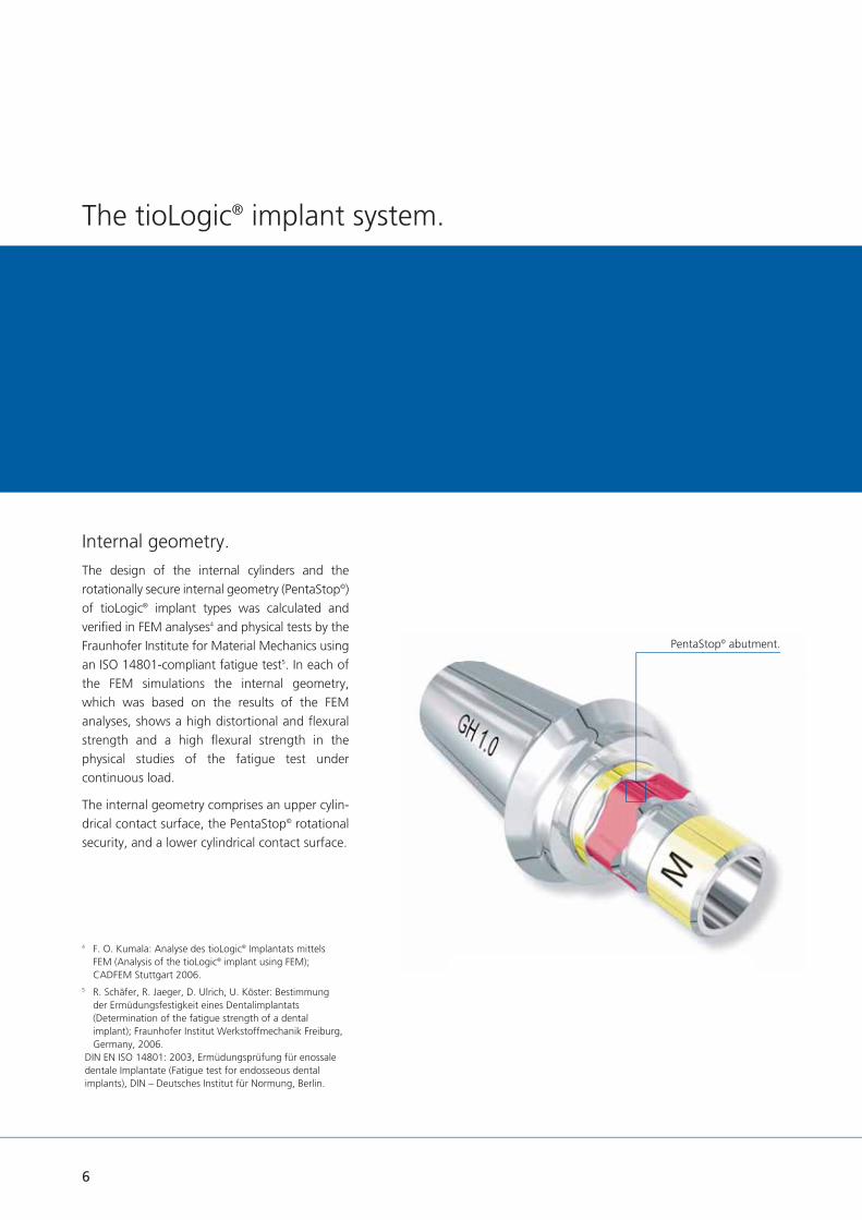
Internal geometry.The design of the internal cylinders and the rotationally secure internal geometry (PentaStop©) of tioLogic® implant types was calculated andverifi ed in FEM analyses4 and physical tests by the Fraunhofer Institute for Material Mechanics using an ISO 14801-compliant fatigue test5. In each of the FEM simulations the internal geometry, which was based on the results of the FEM analyses, shows a high distortional and fl exural strength and a high fl exural strength in the physical studies of the fatigue test under continuous load.
The internal geometry comprises an upper cylin-drical contact surface, the PentaStop© rotational security, and a lower cylindrical contact surface.
4 F. O. Kumala: Analyse des tioLogic® Implantats mittels FEM (Analysis of the tioLogic® implant using FEM); CADFEM Stuttgart 2006.
5 R. Schäfer, R. Jaeger, D. Ulrich, U. Köster: Bestimmung der Ermüdungsfestigkeit eines Dentalimplantats (Determination of the fatigue strength of a dental implant); Fraunhofer Institut Werkstoffmechanik Freiburg, Germany, 2006.
DIN EN ISO 14801: 2003, Ermüdungsprüfung für enossale dentale Implantate (Fatigue test for endosseous dental implants), DIN – Deutsches Institut für Normung, Berlin.
PentaStop© abutment.
7
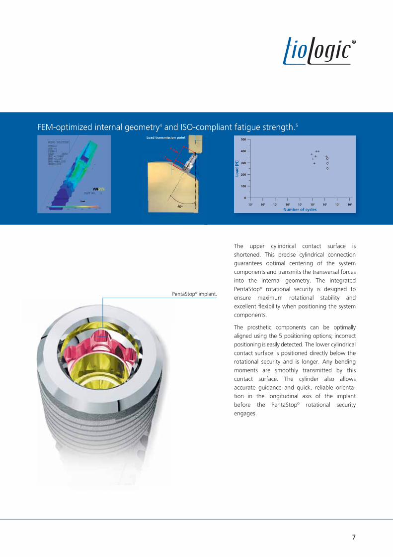
FEM-optimized internal geometry4 and ISO-compliant fatigue strength.5
Load
[N
]
Number of cycles
500
400
300
200
100
0
100 101 102 103 104 105 106 107 108
met yLoad transmission point
8 mm
3 mm
30°
The upper cylindrical contact surface is shortened. This precise cylindrical connection guarantees optimal centering of the system components and transmits the transversal forces into the internal geometry. The integrated PentaStop© rotational security is designed toensure maximum rotational stability and excellent fl exibility when positioning the system components.
The prosthetic components can be optimally aligned using the 5 positioning options; incorrect positioning is easily detected. The lower cylindrical contact surface is positioned directly below the rotational security and is longer. Any bending moments are smoothly transmitted by this contact surface. The cylinder also allows accurate guidance and quick, reliable orienta-tion in the longitudinal axis of the implant before the PentaStop© rotational security engages.
PentaStop© implant.

8
The tioLogic® implant system.
S-M-L concept.
Integrated platform-switching.The optimal grading of implant diameters and lengths ensures that the appropriate implant is used for the indication. Components of the 3 series of abutments are made of plastic (temporaries), titanium and precious metal and include CAD/CAM, bar, ball, bridge, AngleFix, and LOCATOR®
abutments The construction components S are used for the implant diameter 3.3 mm, the construction components M for the implant diameters 3.7 mm and 4.2 mm and the construction components L for the implant diameters 4.8 mm and 5.5 mm. For exact identifi cation all components are laser-marked with S, M or L.
5 implant diameters. 5 implant lengths. 3 series of abutments.
M L
L
LL
ø 4.8 ø 5.5
3 series of abutments.
5 implant diameters.
S
S
S
ø 3.3
M
MM
ø 3.7 ø 4.2

9
LLMMSS
Prosthetic screw
5 implant diameters.
3 series of abutments.
5 implant lengths.
All abutments and implants on a scale of 1:1.
ø 3.3 mm ø 3.7 mm ø 4.2 mm ø 4.8 mm ø 5.5 mm
ST ST ST ST ST
7.0 mm
9.0 mm
11.0 mm
13.0 mm
15.0 mm
tioLogic® tioLogic® tioLogic® tioLogic® tioLogic®

10
Introduction Prosthetics Manual
The prosthetic restoration represents an import-ant aspect if implantation is to be successful long-term. Close contact between the clinician and dental technician, careful pre-prosthetic planning and taking the patient’s wishes into account are all important for the implant-borne restoration to succeed.
The healing phase in the mandible usually takes between three and six months. This phase may be faster or slower depending on the bone quality, healing process and anatomy. Once the healing phase is over and gingiva forming completed, the prosthetic restoration can be commenced.
This laboratory manual uses actual cases to provide a general overview of various types of prosthetic restorations which represent state-of-the-art scientifi c knowledge at the time of going to press. The types of prosthetic restoration shown are subject to continual further development. For further information, please refer to current literature.
The Dentaurum Implants Hotline is manned by experienced implantologists and dental technicians who will be pleased to answer any questions you may have. It provides reassuring information on surgery, implantology and dental technology.
A convincing concept - state of the art.

11
Dental practice record card.To ensure optimal information flow between the operator and dental technician, all relevant data, e.g. the implant diameter, implant length and planned prosthetic restoration, is noted in a record card (REF 989-966-21).
The card is kept with the prosthetic restoration during the entire fabrication procedure. At the fitting stage it is given to the operator along with the finished prosthetic restoration. It contains all the important information for fitting the restoration.
ractice record card.
Turnstr. 31 I 75228 Ispringen I Germany I Phone + 49 72 31 / 803-0 I Fax + 49 72 31 / 803-295
www.dentaurum-implants.com I [email protected]
Date of issue: Patient:First name:Surname:Date of birth:
Practice:
Dental laboratory:
Technician:Date received:
Date sent:
Date sent:
Implant location:18 17 16 15 14 13 12 11
21 22 23 24 25 26 27 28
ø
L
ø
L
ø
L
ø
L
ø
L
ø
L
ø
L
ø
L
Implant dimensions1
(label)After implant placement the adhesive labels included in the implant packaging can be used for documentation.
ø
L
ø
L
ø
L
ø
L
ø
L
ø
L
ø
L
ø
L
Abutment(Refer to label for description)
Prosthetic restoration2
ø
L
ø
L
ø
L
ø
L
ø
L
ø
L
ø
L
ø
L
Implant dimensions1
(label)After implant placement the adhesive labels included in the implant packaging can be used for documentation.
ø
L
ø
L
ø
L
ø
L
ø
L
ø
L
ø
L
ø
L
Abutment(Refer to label for description)
Prosthetic restoration2
48 47 46 45 44 43 42 41
31 32 33 34 35 36 37 38
1 Implant dimensions / Series of abutments (S - M - L concept):
Implant length
7.0 / 9.0 / 11.0 / 13.0 / 15.0 mm
Implant diameter3.3 mm
3.7 mm4.2 mm
4.8 mm5.5 mm
Series of abutmentsS
M
L
All components are marked with the relevant series of abutment S, M or L. The 3.3 mm and 5.5 mm ø implants are not available in 7.0 mm length.
2 Prosthetic restoration:cement-retained / screw-retained
removable
Single restoration Bridgework Resilient bar / Bar attachment Milled barTelescope
Ball attachment LOCATOR®
EB
SG
TK
L
Material information:Alloy:❏
Adhesive: ❏
Ceramic: ❏
Solder:❏
Acrylic:❏
Tooth shade: ❏
Pra
ctice R
eco
rd C
ard
989-
966-
22
Prin
ted
by D
enta
urum
G
erm
any
08
/18/
C/R1
-4
Connector geometry*: ❏ Conical connector ❏ Platform connector
* For tioLogic® TWINFIT only.

12
Diagnosis and planning.
The tioLogic® implant types S ø 3.3 mm are available for patients with narrow alveolar ridges. Due to the smaller diameter and low load capacity (compared to the tioLogic® M ø 4.2 mm implants), these implants have a limited range of indications. In fully edentulous cases, four or more tioLogic® implants with a splinted bar restoration without extension must be inserted. In partially edentulous cases, implant supported restorations must be combined with tioLogic® ø 4.2 mm, ø 4.8 mm or ø 5.5 mm implants and a splinted fi xed prosthetic restoration.
In single restorations, tioLogic® ø 3.3 mm implants should only be used for the lower incisors or the upper lateral incisors and only with a minimum 11.0 mm implant length. Single restorations on tioLogic® ø 3.7 mm, ø 4.2 mm, ø 4.8 mm or ø 5.5 mm implant types require a minimum 9.0 mm implant length.
Care should be taken to avoid an excessive mechanical loading when using ball head abutments together with ø 3.3 mm implants.
Indications.tioLogic® implant types can be used both in the mandible and maxilla for surgical immediate implantation, delayed immediate implantation and delayed implantation using either the one-stage or two-stage technique. Indications for implant insertion are small- and large-bounded saddles (one-tooth restorations, increasing the number of abutments) in the maxilla and mandible, a shortened dentition or an edentulous jaw. The possible benefi ts and disadvantages as well as the risks involved in implant treatment and alternative treatments should be taken into account when considering whether implant treatment is indicated.
In any implantological case the implant diameter and length of the tioLogic® implant types should be in proportion to the prosthetic restoration.
Implants with a minimum diameter of 4.2 mm should always be used for restorations that subject the implant and superstructure to high mechanical loading, if this is practical within the particular oral situation.
This section provides a general overview of diagnosis and planning. For more detailed information on these aspects, please refer to current literature. Implantologists and dental technicians with many years of experience are available to answer any questions that you may have.
The integrated tioLogic® training program also ensures that all the dentists, dental technicians and dental assistants involved in the implant procedure are optimally prepared by experienced lecturers. Dentaurum Implants provides numerous training courses at different levels tailored to suit the target group, the level of knowledge and individual interests.

13
Contraindications.Implants with a diameter of 3.3 mm are not suitable for single-tooth restorations of the central incisor in the maxilla or the canines, premolars or molars in the maxilla or the mandi-ble. It is not permitted to use telescope crown constructions on these implants. The use of LOCATOR® abutments for non-parallel abutments of 10° or more per implant is contraindicative.
General contraindications for dental surgery procedures apply. These include:
reduced immunodefi ciency steroid treatment blood coagulation disorders uncontrolled endocrine diseases rheumatic disorders bone system diseases cirrhosis of the liver drug, alcohol or tobacco abuse depression, psychopathic disorders poor patient compliance chronic infl ammatory diseases
Local contraindications / personal contraindications
osteomyelitis radiotherapy in the head region recurring mucosal diseases temporomandibular joint dysfunctions parafunctions lack of vertical or horizontal bone availability, jaw defects, inadequate bone quality
poor oral hygiene
It should be taken into account that these contraindications may be long- or short-term depending on the extent, duration and individual conditions. The current position of scientifi c implantological associations relating to indica-tions and contraindications and current literature should be taken into consideration when planning implant treatment.
14
Temporary denture. (non-implant-borne)
A temporary prosthetic restoration should not be fi tted until at least 14 days after implant place-ment. Always ensure that there is no mechanical loading on the placed implant. The restoration should be relieved over the implants and fi tted with soft lining. If there are residual teeth, a temporary prosthetic restoration is generally fabricated on the abutment teeth prior to implant placement or an existing denture is converted.
Immediate restoration. (temporary abutment)
It is possible to fi t a long-term, non-functional immediate temporary restoration on implants if there is absolute primary stability and no recession of the implant site. In aesthetically relevant areas the peri-implant structures are retained with a temporary abutment. An optimal impression can then be taken.
Temporary abutments are available for the S, M and L series of abutments. They are supplied non-sterile and made from high-strength plastic (PEEK), which can be quickly and easily customized.
Working procedures.
The temporary abutment can be faced directly with composite or fi tted with a temporary crown or bridge. In both cases the abutment is secured intra-orally with the screw for the temporary abutment; the contours are marked and adjusted extra-orally. The operator can use the polishing aid and AnatomicHold for a better grip. The restoration can only be shortened as far as the upper edge of the screw for the temporary abutment.
With a direct build-up of the facing, the temporary abutment is faced with composite extra-orally and then secured to the implant using the correct torque. With a crown restoration, the temporary abutment is fi tted before sealing the screw aperture with wax and placing the temporary restoration. The crown should only be retained with temporary cement.
Tightening torque Temporary abutment intra-orally: 15 Ncm Temporary abutment on the model: manually
Temporary restoration.

15
Tightening torque Gingiva former: manually or 15 Ncm
Gingiva formers can also be used with open healing of the implant for specifi c indications and for preserving the soft tissue.Important: The gingiva formers and bridge, bar and AngleFix abutments should be sterilized before insertion in the implant.
If a temporary restoration is fi tted, the denture should be relieved during gingiva forming. The impression should not be taken until the tissue is completely free of infl ammation.
Tightening torque Gingiva former: manually or 15 Ncm Bar, bridge, AngleFix abutment: 35 Ncm Bar, bridge, AngleFix closure screw: 15 Ncm
Gingiva former M, conical Gingiva former M, cylindrical
1.5 / 3.0 / 4.5 / 6.0 mm
1.5 / 3.0 / 4.5 / 6.0 mm
5.0 mm 3.7 mm
Implant exposure.The implant is exposed after the healing stage. The patient should be prepared in the same way as for other surgical procedures. The patient is given a local anaesthetic.
For detailed information on implant insertion and implant exposure, pleasre refer to the Surgery Manual (989-959-20).
Gingiva forming.Gingiva formers, conical or cylindrical, or, bar, bridge, AngleFix abutments – particularly gentle on the tissue – are available for the operator to ensure optimal management of the gingiva. The conical gingiva formers are designed to form a wide gingival contour. Depending on the type of prosthetic restoration, this can make it easier for the operator to fi t the restoration. The gingiva formers are selected according to the series of abutments, gingival height and insertion depth of the implant. They are available for the series of abutments S, M or L and in different gingival heights (laser-printed on gingiva former).
Implant exposure.

16
Working procedures.
The impression can be taken using either the open or closed technique. Relevant components are available for both impression techniques.
In the case of removable restorations (resto-rations with bars, bridges, ball abutments, LOCATOR®, AngleFix) the impression can also be taken with other special impression compo-nents over the respective primary abutments.
Silicone or polyether impression materials are recommended for impression-taking due to their high precision and elastic recovery.
Dental practice record card.To ensure optimal information fl ow between the operator and dental technician, all relevant data, e.g. the implant diameter, implant length and planned prosthetic restoration, is noted in a practice record card (REF 989-966-22). The card is kept with prosthetic restoration during the entire fabrication procedure. At the fi tting stage it is given to the operator along with the fi nished prosthetic restoration. It contains all the important information for fi tting the restoration.
Impression-taking.
Impression post, open
Impression postbridge, open
Impression post, closed
Impression postbridge, closed
Impression postAngleFix, open
Impression postAngleFix, closed
Impression post bar, open
17
After the impression has been taken, an individual tray is fabricated. This is strengthened and perforated in the region of the implants.
The temporary restoration and gingiva formers should be removed prior to taking the impres-sion.
The screw is pushed down before fi tting the impression post. This provides additional guidance when fi tting the post. The inner connection is shorter with an open impression to ensure a compression-free impression even with divergent axes.
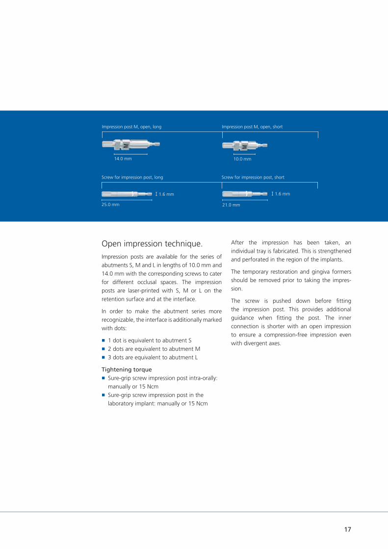
Open impression technique.Impression posts are available for the series of abutments S, M and L in lengths of 10.0 mm and 14.0 mm with the corresponding screws to cater for different occlusal spaces. The impression posts are laser-printed with S, M or L on the retention surface and at the interface.
In order to make the abutment series more recognizable, the interface is additionally marked with dots:
1 dot is equivalent to abutment S 2 dots are equivalent to abutment M 3 dots are equivalent to abutment L
Tightening torque Sure-grip screw impression post intra-orally: manually or 15 Ncm
Sure-grip screw impression post in the laboratory implant: manually or 15 Ncm
14.0 mm 10.0 mm
1.6 mm
Impression post M, open, long Impression post M, open, short
25.0 mm 21.0 mm
Screw for impression post, long Screw for impression post, short
1.6 mm

18
Working procedures.
The impression post corresponding to the series of abutments S, M or L (here M) is fi tted until the rotational security engages. A congruent fi t of the implant post on the implant shoulder is indicated when an optical mark on the screw is level with the upper edge of the impression post (screw should only be inserted and not tightened). If the rotational security is not en-gaged, the mark on the screw is not visible. The impression post should be realigned and checked to ensure that it fi ts correctly (x-ray check).
Impression post M in situ.
Groove sure-grip screw. Marking at interface M. When fi tting the custom tray, ensure that there is no contact between the impression posts or screws and the tray at the perforations.
Open impression post M with tray.
Impression-taking.

19
Impression post M in the open impression tray.Impression post M, open at impression-taking.
The tray with the screws is sent to the dental laboratory.
The dental technician obtains all the relevant information from the practice record card (REF 989-966-22).
The respective gingiva formers are refi tted after the impression has been taken.
The impression should be taken with a silicone or polyether material. The impression posts are secured in the impression material with the retention. Ensure that the peri-implant region is accurately reproduced in the impression.
The screws are loosened and retracted to remove the impression tray.
Loosening the sure-grip screw.Impression post M prior to impression-taking.
14.0 mm 10.0 mm
1.6 mm
Impression post M, open, long Impression post M, open, short
25.0 mm 21.0 mm
Screw for impression post, long Screw for impression post, short
1.6 mm

Turnstr. 31 I 75228 Ispringen I Germany I Phone + 49 72 31 / 803-0 I Fax + 49 72 31 / 803-295
www.dentaurum-implants.com I [email protected]
Date of issue: Patient:First name:Surname:Date of birth:
Practice:
Dental laboratory:
Technician:Date received:
Date sent:
Date sent:
Implant location:18 17 16 15 14 13 12 11
21 22 23 24 25 26 27 28
ø
L
ø
L
ø
L
ø
L
ø
L
ø
L
ø
L
ø
L
Implant dimensions1
(label)After implant placement the adhesive labels included in the implant packaging can be used for documentation.
ø
L
ø
L
ø
L
ø
L
ø
L
ø
L
ø
L
ø
L
Abutment(Refer to label for description)
Prosthetic restoration2
ø
L
ø
L
ø
L
ø
L
ø
L
ø
L
ø
L
ø
L
Implant dimensions1
(label)After implant placement the adhesive labels included in the implant packaging can be used for documentation.
ø
L
ø
L
ø
L
ø
L
ø
L
ø
L
ø
L
ø
L
Abutment(Refer to label for description)
Prosthetic restoration2
48 47 46 45 44 43 42 41
31 32 33 34 35 36 37 38
1 Implant dimensions / Series of abutments (S - M - L concept):
Implant length
7.0 / 9.0 / 11.0 / 13.0 / 15.0 mm
Implant diameter3.3 mm
3.7 mm4.2 mm
4.8 mm5.5 mm
Series of abutmentsS
M
L
All components are marked with the relevant series of abutment S, M or L. The 3.3 mm and 5.5 mm ø implants are not available in 7.0 mm length.
2 Prosthetic restoration:cement-retained / screw-retained
removable
Single restoration Bridgework Resilient bar / Bar attachment Milled barTelescope
Ball attachment LOCATOR®
EB
SG
TK
L
Material information:Alloy:❏
Adhesive: ❏
Ceramic: ❏
Solder:❏
Acrylic:❏
Tooth shade: ❏
Pra
ctice R
eco
rd C
ard
989-
966-
22
Prin
ted
by D
enta
urum
G
erm
any
08
/18/
C/R1
-4
Connector geometry*: ❏ Conical connector ❏ Platform connector
* For tioLogic® TWINFIT only.
Working procedures.
To achieve a stable apposition of the gingiva with bar, bridge and AngleFix abutments, you can either take an impression on implants according to conventional methods or take an impression on bar, bridge and AngleFix abutments that are fi tted in the mouth.
The impression can be taken using either the open or closed technique. The impression is taken with special impression components, which are identical for the series of abutmentsS, M and L, over the respective bar, bridge and AngleFix abutments.
Silicone or polyether impression materials are recommended for impression-taking due to their high precision and elastic recovery.
Dental practice record card.To ensure optimal information fl ow between the operator and dental technician, all relevant data, e.g. the implant diameter, implant length and planned prosthetic restoration, is noted in a practice record card (REF 989-966-22). The card is kept with prosthetic restoration during the entire fabrication procedure. At the fi tting stage it is given to the operator along with the fi nished prosthetic restoration. It contains all the import-ant information for fi tting the restoration.
Bar abutment Bridge abutment AngleFix abutment
Impression-taking.
20

Bar abutments in situ.
Open impression posts for bar abutments in situ.Taking an impression over bar, bridge and AngleFix abutments.To achieve a stable apposition of the gingiva with bar, bridge and AngleFix abutments, you can either take an impression on implants (as described on p. 17) or on bar, bridge and AngleFix abutments that are fi tted in the mouth.
To that end, the bar, bridge or AngleFix abutment is fi xed on the implant and the
Following this, the impression is taken with an open impression tray. Once the impression material has set, the sure-grip screws are loosened, pushed upwards and the impression tray is removed together with the impression posts. The abutments are then covered with the corresponding closure screws.
In the laboratory, the laboratory implant bar, bridge or AngleFix is fi xed on the impression post with the screw. The upper section of this laboratory implant is identical to that of the respective abutment.
Tightening torque Sure-grip screw impression post: 15 Ncm Closure screw on bar, bridge, AngleFix abutment intra-orally: 15 Ncm
10.0 mm 10.0 mm
10.0 mm 8.0 mm
13.0 mm
Impression post bar Impression post bridge
Groove sure-grip screw.
corresponding open impression post is placed. A congruent fi t of the impression post on the abutment is indicated when an optical mark on the screw is level with the upper edge of the impression post (screw is only pushed into place, not fi xed). If the impression post does not fi t fl ush, the marking on the screw will not be visi-ble. The impression post should be aligned again, checked for correct fi t and fi xed with the screw.
Impression post AngleFix
8.0 mm
21
22
Working procedures.
Impression post M, closed
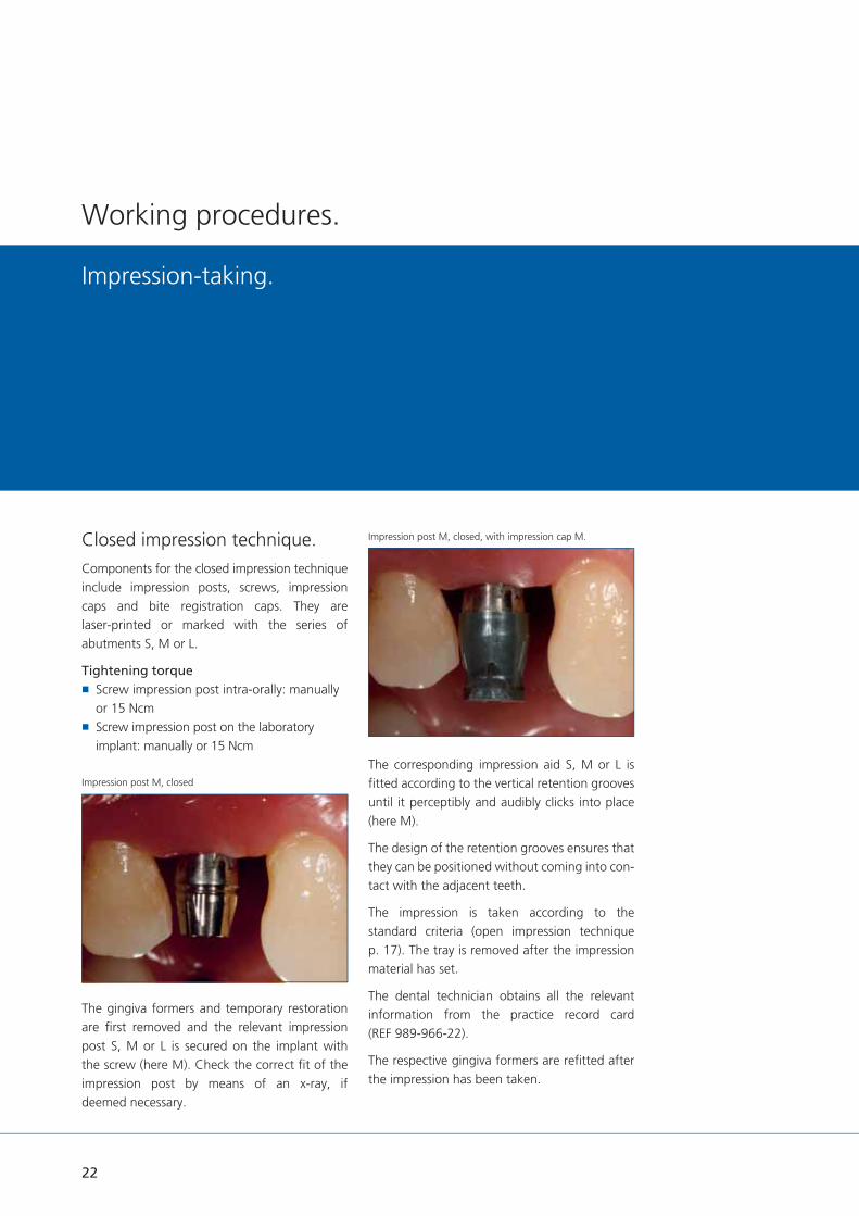
Closed impression technique.Components for the closed impression technique include impression posts, screws, impression caps and bite registration caps. They are laser-printed or marked with the series of abutments S, M or L.
Tightening torque Screw impression post intra-orally: manually or 15 Ncm
Screw impression post on the laboratory implant: manually or 15 Ncm
The gingiva formers and temporary restoration are fi rst removed and the relevant impression post S, M or L is secured on the implant with the screw (here M). Check the correct fi t of the impression post by means of an x-ray, if deemed necessary.
The corresponding impression aid S, M or L is fi tted according to the vertical retention grooves until it perceptibly and audibly clicks into place (here M).
The design of the retention grooves ensures that they can be positioned without coming into con-tact with the adjacent teeth.
The impression is taken according to the standard criteria (open impression technique p. 17). The tray is removed after the impression material has set.
The dental technician obtains all the relevant information from the practice record card (REF 989-966-22).
The respective gingiva formers are refi tted after the impression has been taken.
Impression post M, closed, with impression cap M.
Impression-taking.

23
7.0 mm
6.0 mm
6.0 mm
Impression post M, closed impression cap M bite registration cap. M
Impression tray with impression cap M
Bite registration.Bite registration caps are available for registering the bite before or after taking the impression. These caps, which are also laser-printed with the series of abutment S, M or L (here M). They click, both perceptibly and audibly, into place on the impression posts.
Impression caps and bite registration caps are single-use products. They are not suitable for sterilization. Multiple use results in transfer in-accuracies.
Tightening torque Sure-grip screw impression post intra-orally: manually or 15 Ncm
Sure-grip screw impression post in the laboratory implant: manually or 15 Ncm

Closed impression technique on bridge and AngleFix abutments.Impression posts including screws and impres-sion caps are available for taking the closed impression.
When taking the closed impression the AngleFix and bridge abutment is fi xed in position in the implant and the corresponding impression post for the closed impression is screw-retained on the abutment. The appropriate impression cap is fi tted taking into account the vertical retention grooves until it can be clearly felt and heard snapping into position. The retention grooves are designed so that it is possible to position a groove without touching adjacent teeth.
7.5 mm
7.5 mm
5.8 mm
5.8 mm
5.8 mm
5.8 mm
Impression post AngleFix, closed incl. impression cap and bite registration cap.
Impression post bridge, closed incl. impression cap and bite registration cap.
Working procedures.
The impression is taken according to the usual criteria (see section closed impression technique) p. 22. After the impression material has cured, the tray is removed. The impression posts with screws are delivered to the laboratory together with the impression.
Tightening torque Sure-grip screw impression post: 15 Ncm
Closure screw on AngleFix or bridge abutment intra-orally: 15 Ncm
24
25
Quality isyour demand andour expertise.
Dental technologysetting standards.The Dentaurum Group develops, produces and sells products for dentists and dental technicians worldwide. The variety of products for dental technology, orthodontics and implantology is unique in the dental world. Dentaurum Implants, a manufacturer of implants, is a subsidiary of Dentaurum.
Quality inspires confidence.As the oldest dental company in the world, we have worldwide experience with high-quality dental products. Our market success is based on consistent implementation of customer and market demands. This is why we are committed to the constant further development of the company and to continuous improvement of the quality of our processes and products.
Service as added value.There are many reasons for using Dentaurum Group products both in the dental practice and in the laboratory. Quality is the decisive factor. Our company philosophy is to offer not only high quality products, but to add to this by offe-ring additional services. We offer a wide-ranging training program for new and advanced users with an internationally experienced team of course instructors. Contact us for further infor-mation.

26
Casting the model.
Working procedures.
Open impression technique.In order to check the exact fi t of the impression post, the impression material is removed from the occlusal surface to the top edge of the impression post. Before the laboratory implant is inserted, it can be clearly read off the impression post interface whether an S, M or L abutment is required.
Before the laboratory implant is inserted, the screw is pushed downwards into the impression post. This guarantees additional guidance during insertion.
The laboratory implant corresponding to the abutment S, M or L is put into place (in this case M), until the rotational security engages. The impression post fi ts the laboratory implant
congruently when the visible marking on the screw is in line with the upper edge of the impression post (screw is only pushed into place, not fi xed). If the rotational security is not engaged, then the marking on the screw is not visible. The impression post should be adjusted again and re-checked for correct fi t.
Tightening torque Sure-grip screw impression post in the laboratory implant: manually or 15 Ncm
Fabricating the gingival mask.An elastic gingival mask is recommended for use on implant restorations. This provides the optimal reproduction of the crown contour and, when removed, it allows a full view of the implant cervical section. This allows the exact fi t of the abutment to be checked and monitored.
The elastic gingival mask is applied directly to the implant area within the impression.
Caution: The two types of silicone could bond inseparably, it is therefore essential to fi rst apply a separating agent.
In the case of removable restorations (resto-rations with bars, bridges, ball abutment, LOCATOR®, AngleFix) the impression and model casting can also be effected with other special impression components.
12.0 mm
Laboratory implant M.
Gingival mask in the impression.
Groove sure-grip screw. Marking at interface M.

27
Casting the plaster model.After the gingival mask material has set, the impression can be cast in plaster. The dental arch is cast in the usual manner and the base added. The laboratory implants must fi t precisely.
The screws must be removed before the impres-sion tray is lifted off.
Loosening the sure-grip screws. Model with gingival mask.
Model without gingival mask.

28
Closed impression technique.All laboratory implants, impression posts and impression caps are laser-printed or marked with the appropriate abutment series S, M or L.
The S, M or L laboratory implant is wound into the respective impression post. Next, the impression post is placed in the impression cap, taking the diameter S, M or L, and the vertical retention groove into consideration, until a click can be both heard and felt. The laboratory implant, screwed to the impression post, must be placed into the impression cap and this securely fi xed into the impression material.
Tightening torque AnoTite screw impression post in laboratory implant: Manually or 15 Ncm
The gingival mask and the plaster model are fabricated using the same method as described in the section Casting the model – the open impression technique. Loosening and removal of the sure-grip screw is not applicable to the closed impression method. The impression tray can be released directly from the model.
Impression caps and bite registration caps are disposable items. They are not suitable for sterilisation. Multiple use leads to transfer discrepancies.
Both components can be re-ordered separately.
In the case of removable restorations (restorations with bars, bridges, ball abutment, LOCATOR®, AngleFix) the impression and model casting can also be effected with other special impression components.
Impression tray with impression cap M
Working procedures.
Casting the model.
12.0 mm
Laboratory implant M

29
The open impression techniquebridge, bar and AngleFix.In order to check the exact fi t of the impression post, the impression material is removed from the occlusal surface to the top edge of the impression post. Before each laboratory implant is inserted, the screw is pushed downwards into the impression post. This guarantees additional guidance during insertion.
Tightening torque Sure-grip screw impression post:In laboratory implant manually or 15 Ncm
Fabricating the gingival mask.An elastic gingival mask is recommended for fabricating a gingival mask. This provides the optimal reproduction of the suprastructure and, when removed, it allows a full view of the implant cervical section. This allows the exact fi t of the abutment to be checked. The elastic gingival mask is applied directly to the implant area within the impression.Caution: The two types of silicone could bond inseparably, it is therefore essential to fi rst apply a separating agent.
Casting the plaster model.After the gingival mask material has set, the dental arch is cast in the usual manner and the base added. The laboratory implants must fi t precisely. The screws must be removed before the impression tray is lifted off.
The closed impression technique bridge and AngleFix. The laboratory implant is screwed into the respective impression post. Next, the impression post is placed in the impression cap, taking the vertical retention groove into consideration, until a click can be both heard and felt. The laboratory implant, screwed to the impression post, must be placed into the impression cap and this securely fi xed into the impression material.
Tightening torque AnoTite screw impression post in laboratory implant: Manually or 15 Ncm
Fabricating the gingival mask. The gingival mask and the plaster model arefabricated using the same method as described in the section Casting the model – the open impression technique. Loosening and removal of the sure-grip screw is not applicable to the closed impression method. The impression tray can be released directly from the model.
Impression caps and bite registration caps are single-use products. They are not suitable for sterilization. Multiple use results in transfer inaccuracies. Both components can be re-ordered separately.
10.0 mm 14.0 mm 16.0 mm
Laboratory implant bar Laboratory implant bridge Laboratory implant AngleFix

30
Selection aid S
Selection aid M
Selection aid L

31
Wax-up / set-up,lingual overcast or palatal overcast.An overcast can be adapted to the lingual or palatal aspects of the model, in order to deter-mine the amount of space available. For this, a silicone overcast is built over a wax-up / set-up of the planned prosthetic restoration. The overcast is cut in half along the occlusal medial lineproducing a lingual overcast and a palatal overcast. With this overcast it is possible to determine the amount of space available exactly.
Abutments – selection aidsAfter having completed the models with the overcasts, the abutment components may be selected. This selection depends upon the implant axis, gingival height, amount of space available to the antagonists and the material to be used for the abutment and planned restoration.
In order to simplify matters for the dental technician, there are various acrylic selection aids available for the abutment series S, M and L. These were designed specifi cally as selection aids for the laboratory and must not be used for the actual prosthetic restoration.

32
Every implant restoration requires exact pre-prosthetic planning. Apart from the anatomical aspects, the prosthetic components and processing (cementation / screw fi xation) are also determined.For every abutment series there are S, M or L components available in the materials ceramic (case 1), precious metal (case 2) and titanium (case 3) for individual, fi xed restorations on implants.
Single restorationsThe decisive factor for a single restoration is the optimal proportion – crown length to implant length. In order to achieve a long term, stable, single restoration, an optimal proportion between crown and inserted implant length must be ensured (see practice record card). If this value is exceeded, then it is preferable to fabricate a bridge restoration on two or more abutment teeth instead.
Case 1:Full ceramic anterior restoration, cemented. Titanium bases are used for the fabrication of customized hybrid abutments for adhesively bonding CAD/CAM zirconium oxide ceramic mesostructures. The geometry of the titanium bases was specially designed to ensure a reliable, aesthetic bond with the ceramic mesostructure.
Dental technical variants. ø
3.7
mm
ø 4
.2 m
m
ø 4
.8 m
m ø
5.5
mm
ø 3
.3 m
m
S M L
Fixed restorations.

33
Tightening torque Prosthetic screw scan abutment on model and intra-orally: manually
Prosthetic screw CAD/CAM titanium base on model: manually
AnoTite screw CAD/CAM titanium base intra-orally: 30 Ncm
CAD/CAM manufacturing.
The scan abutments are available in the S, M or L series of abutments. The scan abutment is placed on the implant or on the laboratory implant (pay attention to the rotational security) and fi xed with the prosthetic screw L 9.0 mm.
After selecting the indication (here: hybrid abutments) in the tioLogic® data set of the respec-tive software, the scan abutments can be scanned.
The matching process and design are carried out according to the instructions of the software manufacturer and dental rules.
The AnatomicHold (a universal holder) is available with two holders for the milled ceramic sleeve, in order to make processing easier for the technician.
One holder is available for the ceramic sleeve in the abutment series S and M and the second for the abutment series L. The holders are marked accordingly.
Ceramic abutment on holder.
Ceramic abutment, trimmed.
The relevant ceramic abutment holder is placed into the AnatomicHold and fi xed securely to prevent rotation with a grub screw (SW 0.9). Then the holder fi xation screw is slightly loosened and the ceramic sleeve is positioned. Ensure that the rotational stop integrated within the abutment and the holder are congruent.
CAD/CAM titanium base
Ceramic abutment holder M
Polishing aid M
12.0 mm
Scan abutment M

34
Dental technical variants.
The following parameter must be taken into consideration when designing the ceramic abutment:
The thickness of the ceramic abutment must be no less than 0.5 mm
Prepare a chamfer with angled inner edge and a minimum step of 0.5 mm
The height of the ceramic abutment must be no less than 7.0 mm in its entire length (not including the titanium base)
The ceramic sleeve is fi xed by tightening the fi xation screw (manually max. 15 Ncm).
Model with trimmed ceramic abutment, labial view.Ceramic abutment withCAD/CAM titanium base.
Ceramic abutment withCAD/CAM titanium base.
Fixed restorations.
AnatomicHold AnatomicTwist
35
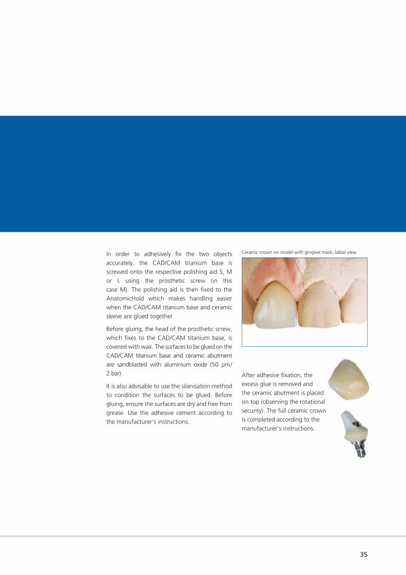
Ceramic crown on model with gingival mask, labial view.In order to adhesively fi x the two objects accurately, the CAD/CAM titanium base is screwed onto the respective polishing aid S, M or L using the prosthetic screw (in this case M). The polishing aid is then fi xed to the AnatomicHold which makes handling easier when the CAD/CAM titanium base and ceramic sleeve are glued together.
Before gluing, the head of the prosthetic screw, which fi xes to the CAD/CAM titanium base, is covered with wax. The surfaces to be glued on the CAD/CAM titanium base and ceramic abutment are sandblasted with aluminium oxide (50 μm / 2 bar).
It is also advisable to use the silanisation method to condition the surfaces to be glued. Before gluing, ensure the surfaces are dry and free from grease. Use the adhesive cement according to the manufacturer’s instructions.
After adhesive fi xation, the excess glue is removed and the ceramic abutment is placed on top (observing the rotational security). The full ceramic crown is completed according to the manufacturer’s instructions.

36
Dental technical variants.
Case 2:Bonded anterior restoration, cemented, precious metal abutment.Precious metal abutments are available for the abutment series S, M and L. The precious metal abutment consists of a cast-on base made from a precious metal alloy, an acrylic extension and an AnoTite screw. The abutment construction makes individualization easy and is extremely precise, due to the pre-fabricated inner joint.
Tightening torque AnoTite screw, precious metal abutmenton model: manually
AnoTite screw, precious metal abutmentintra-orally: 30 Ncm
The precious metal abutment is placed on the laboratory implant (pay attention to the rotational security) and fi xed with the prosthetic screw L 9.0 mm. The acrylic extension is shortened and trimmed according to the amount of space available occlusally and anatomically.The precious metal abutment is removed, then the mesio construction is waxed-up. A precious metal alloy must be used to cast-on to the precious metal base.
As for case 1 (ceramic abutment, p. 32), the model with the integrated laboratory implant and gingival mask is articulated. The occlusal space is checked.
3.0 mm
3.7 mm
0.6 mm
11.4 mm
Precious metal abutment M, straight
Precious metal abutment with gingival mask, labial view.
Precious metal abutment and gingival mask, articulated.
Model with shortened precious metal abutment, labial view.
Model with trimmed precious metal abutment, labial view.
Fixed restorations.
37
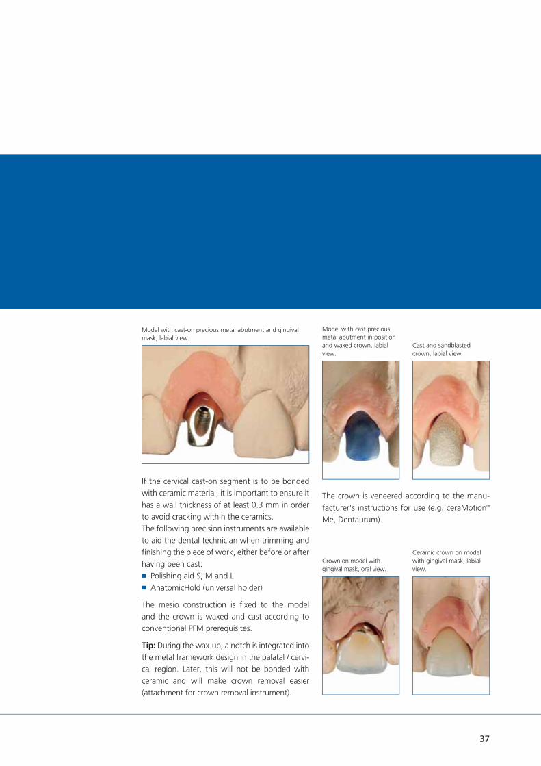
Model with cast-on precious metal abutment and gingival mask, labial view.
If the cervical cast-on segment is to be bonded with ceramic material, it is important to ensure it has a wall thickness of at least 0.3 mm in order to avoid cracking within the ceramics.The following precision instruments are available to aid the dental technician when trimming and fi nishing the piece of work, either before or after having been cast:
Polishing aid S, M and L AnatomicHold (universal holder)
The mesio construction is fi xed to the model and the crown is waxed and cast according to conventional PFM prerequisites.
Tip: During the wax-up, a notch is integrated into the metal framework design in the palatal / cervi-cal region. Later, this will not be bonded with ceramic and will make crown removal easier (attachment for crown removal instrument).
The crown is veneered according to the manu-facturer’s instructions for use (e.g. ceraMotion®
Me, Dentaurum).
Model with cast precious metal abutment in position and waxed crown, labial view.
Cast and sandblasted crown, labial view.
Crown on model with gingival mask, oral view.
Ceramic crown on model with gingival mask, labial view.

38
Dental technical variants.
Case 3:Bonded anterior restoration, cemented, titanium abutment 20°.Titanium abutments are available in the abut-ment series S, M and L, in straight, angled (S 15°, M 20° and L 20°) and universal form. The straight and angled titanium abutments can be slightly altered to adapt to the gingival line (straight 1.0 mm, 2.5 mm and 4.0 mm, angled 1.5 mm and 3.0 mm). These abutments have an exactly defi ned crown margin and an integrated rotational stop. The angled titanium abutments are also available in different gingival heights (labial / palatal). The universal titanium abut-ments are cylindrical and can be prepared as required.
Tightening torque Prosthetic screw, titanium abutment on model: manually
AnoTite screw, titanium abutment intra-orally: 30 Ncm
The angled titanium abutment M 20°, GH 1.5 mm is used in the case described below.When the abutment is inserted, the occlusal space and the axial direction must be checked. Both can be altered by marking where neces-sary. The titanium abutment is fi xed onto the model with the AnoTite screw.The following precision instruments are available for processing the titanium abutment:
Polishing aid S, M and L AnatomicHold (universal holder)
Angled titanium abutment and gingival mask, labial view.
Angled titanium abutment and gingival mask, oral view.
Model with shortened, angled titanium abutment, labial view.
Angled titanium abutment on polishing aid.
1.0 / 2.5 / 4.0 mm
4º
6.0 mm
1.5 / 3.0 mm
6.0 mm
Titanium abutment M
straight angled
2.5 / 4.0 mm
º4º 20º
Fixed restorations.
39
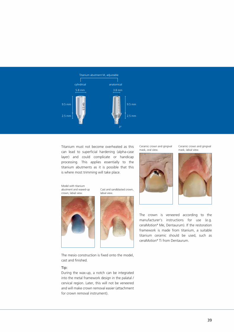
Model with titanium abutment and waxed-up crown, labial view.
Titanium must not become overheated as this can lead to superfi cial hardening (alpha-case layer) and could complicate or handicap processing. This applies essentially to the titanium abutments as it is possible that this is where most trimming will take place.
The crown is veneered according to the manufacturer’s instructions for use (e.g. ceraMotion® Me, Dentaurum). If the restoration framework is made from titanium, a suitable titanium ceramic should be used, such as ceraMotion® Ti from Dentaurum.
Ceramic crown and gingival mask, oral view.
Ceramic crown and gingival mask, labial view.
The mesio construction is fi xed onto the model, cast and fi nished.
Tip:During the wax-up, a notch can be integrated into the metal framework design in the palatal / cervical region. Later, this will not be veneered and will make crown removal easier (attachment for crown removal instrument).
Cast and sandblasted crown, labial view.
Titanium abutment M, adjustable
cylindrical anatomical
2.5 mm 2.5 mm
9.5 mm 9.5 mm
5.8 mm 3.8 mm
3º

40
Model with gingival mask and waxed-up acrylic cap, adhered, buccal view.
Model with marked abutment in position, buccal view.
Dental technical variants.
Bridge restoration.Free-end cemented, titanium abutment straight.The straight titanium abutments are selected according to the gingival conditions. There are three different gingival heights available in the abutment series S, M and L (1.0 mm, 2.5 mm and 4.0 mm). The titanium abutments can be customized according to the gingival line. The height of the coronal part of each abutment is 6.0 mm and can be shortened according to occlusal space requirements. The precision instruments (see p. 78 ff.) are suitable for trimming and fi nishing the piece of work. The titanium abutment is fi xed with the supplied AnoTite screw L 9.0 mm.
Tightening torque Prosthetic screw, titanium abutment on model: manually
AnoTite screw, titanium abutment intra-orally: 30 Ncm
The following case uses two straight titanium abutments M, GH 1.0 mm and one straight titanium abutment L, GH 1.0 mm.
Model with gingival mask and titanium abutment, buccal view.
Fixed restorations.
1.0 / 2.5 / 4.0 mm
4º
6.0 mm
1.5 / 3.0 mm
6.0 mm
Titanium abutment M
straight angled
2.5 / 4.0 mm
º4º 20º

41
Model with cast bridge framework and gingival mask, oral view.
Model with anatomical pattern, mesiobuccal view.
Important: It is essential that the framework has an absolutely passive fi t on the titanium abutments.
Tip: If the implant abutments have different implant diameters it is a good idea to mark each individual piece in order to avoid any mix-up during insertion or positioning.
The proximal areas should be designed so that the implant neck may be cleaned with an interdental brush.
The crown caps are fabricated and connected using the same fully burn-out resin, in order to achieve an accurate fi t of the bridge later.
Next the framework is designed according to dental technical prerequisites (reduced fi nal
anatomical shape). The waxes from Dentaurum which also burn without leaving a residue (StarWax range) are suitable.
The metal alloy is cast and processed according to the relevant manufacturer’s instructions.
Tip: During the wax-up, a notch can be integrat-ed into the metal framework design in the palatal / cervical region. Later, this will not be veneered which will make crown removal easier (attachment for crown removal instrument).
Model with bonded bridge in position, distobuccal view.
Titanium abutment M, adjustable
cylindrical anatomical
2.5 mm 2.5 mm
9.5 mm 9.5 mm
5.8 mm 3.8 mm
3º

42
Dental technical variants.
tioLogic® digital. from Dentaurum Implants provides a coordinated complete solution for CAD/CAM processes on tioLogic® implants.
At www.dentaurum-implants.com/cadcam
Dentaurum Implants provides a download service for tioLogic® CAD/CAM data records for 3shape, dental wings and exocad and integrates them into the respective software. The data records were created and verifi ed in collabora-tion with these manufacturers.
The download begins after selection of the relevant software provider. The download contains all data for every type of restoration as a complete package.
The scan abutments were specially designed for precise digital recording of the geometry directly on the implant shoulder.
Titanium bases are used for the fabrication of customized hybrid abutments for adhesively bonding CAD/CAM zirconium oxide ceramic mesostructures.
The geometry of the titanium bases was specially designed to ensure a reliable, aesthetic bond with the ceramic mesostructure.
Original tioLogic® CAD/CAM titanium blocks are available during fabrication of customized one-piece abutments.
CAD/CAM manufacturing.The scan abutments are available in the S, M or L series of abutments. The scan abutment is placed on the implant or on the laboratory im-plant (pay attention to the rotational security) and fi xed with the prosthetic screw L 9.0 mm.
After selecting the indication (here: one piece abutments or hybrid abutments) in the tioLogic®
data set of the respective software, the scan abutments can be scanned.
The matching process and design are carried out according to the instructions of the software manufacturer and dental rules.
Scan abutment M CAD/CAM titanium block M, PreForm
CAD/CAM.
CAD/CAM titanium base M

43
4. Wax-up.1. Data matching
5. Finished wax up without model.2. Insertion direction
6. Completely designed one piece abutment.3. Wax-up with opposing teeth.

44
Dental technical variants.
Apart from the anatomical aspects, the prosthetic components and their processing techniques (cementation / screw fi xation) are also determined during the planning phase.
When constructing an operator-removable prosthetic restoration, it is essential to use only the precious metal abutments, which are available in the abutment series S, M and L.
Tightening torque Prosthetic screw, precious metal abutment on model: manually
AnoTite screw, precious metal abutment intra-orally: 30 Ncm
Single restorationsCase: premolar, occlusal screw fi xation, precious metal abutment.
The prosthetic restoration in the case described below uses the precious metal abutment L.
The precious metal base consists of a cast-on precious metal alloy.
The precious metal abutment is placed on the laboratory implant (pay attention to the rotational security) and fi xed with the prosthetic screw L 9.0 mm.
The wax-up is prepared according to the conventional PFM prerequisites and is then fabricated directly from the gingival margin.
The acrylic extension is shortened and trimmed according to the amount of space available occlusally and anatomically.
3.0 mm
3.7 mm
0.6 mm
11.4 mm
Precious metal abutment M, straight
Model with gingival mask and precious metal abutment, buccal view.
Model with gingival mask and shortened precious metal abutment, buccal view.
Operator-removable restorations

45
Precious metal abutment with waxed pattern in situ, buccal view.
Model with gingival mask and bonded crown in situ, buccal view.
Using a permanent marker, the gingival line is marked on the abutment.
A precious metal alloy (e.g. DentAurum Bio or DentAurum LFC, from Dentaurum) is used to cast-on to the precious metal base. If the collar of the precious metal base is to be bonded with ceramic material, it is important to ensure it has a wall thickness of at least 0.3 mm in order to avoid cracking within the ceramics.
The following precision instruments are available to aid the dental technician when trimming and fi nishing the piece of work, either before or after having been cast:
Polishing aid S, M and L AnatomicHold (universal holder)
Trimming and veneering are carried out according to the manufacturer's instructions.The following procedure warrants an individual marginal design.
Cast and sandblasted crown in situ, buccal view.
Bonded crown with sealed screw aperture, buccal view.

Dental technical variants.
Operator-removable restorations
Bridge restoration.Bridge abutments are available for the S, M and L series of abutments. The gingival heights are 1.0 mm, 2.5 mm and 4.0 mm. The seating surface of the bridge abutments should be approx. 0.5 mm above the gingiva.
The bridge abutments can compensate for implants which diverge / converge by up to 40°.
Passive fi t (“Sheffi eld Test“).After lasering or casting, every bridge restoration must be checked for passive fi t on the model and prior to placing it intra-orally. This involves placing the bridge restoration on the bridge abutments and fi xing it to the bridge abutment with only one prosthetic screw (torque 25 Ncm). If this raises the bar to create a gap between the bridge and abutment, stresses are present and must be eliminated.
For restorations with temporary (case 1) or individually cast (case 2) milled (case 3) bridges, the appropriate caps are secured on the bridge abutments:
GH 1.0 mm GH 2.5 mmGH 4.0 mm
4.1 mm 4.1 mm 4.1 mm
Bridge abutment M
Case 2: Plastic cap
Case 1: Titanium cap
The seating surface and cone (20 °) for the caps on the bridge abutments is identical (ø 4.1 mm) for the S, M and L series of abutments. The same AnoTite screw, bridge abutment (L 6.0 mm) is used for all caps. The bridge abutment is placed with the bar, bridge, AngleFix abutment insertion key (secure the counter screw!).
Tightening torque Bridge abutments on model: manually Bridge abutments intra-orally: 35 Ncm Cap on bridge abutment on the model: manually
Cap on bridge abutment intra-orally: 25 Ncm Sure-grip screw impression post on bridge abutment intra-orally: 15 Ncm
Closure screw in bridge abutment intra-orally: 15 Ncm
Case 3: Scan cap bridge abutment
The bar, bridge and AngleFix abutments can be combined and used for bar and bridge constructions depending on the clinical situation.
46

3.2 mm
Case 1: Temporary restoration.The bridge titanium caps are secured in position on the bridge abutments using the AnoTite screw L 6.0 mm for fabricating a temporary restoration.
The available space is checked using the lingual and palatal overcasts. If there is insuffi cient space available, the bridge titanium caps can be lightly and easily trimmed.
Titanium must not become overheated as this can lead to superfi cial hardening (alpha-case layer) and could complicate or handicap processing.
A wax set-up is then fabricated, which can be checked using the lingual and palatal overcasts.
Before waxing up the temporary restoration, ensure that there is an adequate, uniform cement gap between the bridge titanium caps and the temporary restoration by blocking out using preparation and casting wax (e.g.: Dentaurum REF 120-025-00). This guarantees a stress-free fi xation.
Finishing, trimming and polishing should be completed according to the instructions of the acrylic manufacturer.
PTFE cylinder pins are available for restorations which are bonded in the laboratory. The pins do not bond with the adhesive and prevent it getting into the screw aperture.
3.3 mm
Case 2: Bridge long-term restoration.The bridge plastic caps are secured in position on the bridge abutments using the AnoTite screw L 6.0 mm.
The available space is checked using the lingual and palatal overcasts. If there is insuffi cient space available, the bridge plastic caps can be lightly and easily trimmed.
A base structure is then fabricated as a strengthener for a long-term restoration. The wax-up is fabricated taking into consideration the lingual and palatal overcasts. The waxes from Dentaurum which burn without leaving a residue (StarWax range) are suitable. This procedure guarantees that there is still suffi cient space for subsequent working stages and the pre-prosthetic planning can be maintained.
Case 3: CAD/CAM manufacturingThe scan caps bridge abutments are fi xed with the prosthetic screw L 6.0 mm on the bridge abutments.
After selecting the indication (here: bridge abutments) in the tioLogic® data set of the respective software, the scan caps bridge abutments can be scanned.
The matching process and design are carried out according to the instructions of the software manufacturer and dental rules.
4.4 mm
10.8 mm
Titanium cap bridge
4.1 mm
10.8 mm
Scan cap bridge abutment
4.1 mm
Plastic cap bridge
10.0 mm
47

Dental technical variants.
AngleFix restoration.Due to the steep inclination of the implants a splinted denture is absolutely essential.
Fitting the AngleFix abutments.When fi tting the angulated AngleFix abutments ensure that the abutments have a larger diameter than the implants. As part of the abutments may be below the bone line, the bone may have to be removed in this region, if required, so that the abutment sits fl ush on the implant. A prerequisite for successful use of the AngleFix system is the best possible accurate angular position of the implant. The more accu-rate this angle can be maintained, the easier the prosthetic treatment, as the abutments are then positioned parallel to one another.
To ensure that the implants are reliably placed in this angle we recommend the use of navigated implant placement with the tioLogic® pOsition system (see Surgery Manual pOsition for tioLogic® REF 989-999-20).
Alternatively or as a control instrument there are angle aids available with 18° and 32°, which are used as orientation for implants in situ.
5.3 mm 5.3 mm 5.3 mm
1.0 mm
2.5 mm
4.0 mm 4.0 mm
2.5 mm
4.0 mm
24º 24º 24º
00ºº 1818ºº 3232ºº
AngleFix abutments 0°, 18° and 32°.
Implant position in the mouth
The AngleFix abutments are provided in 3 angulations: 0°, 18° and 32°. The cone of the AngleFix abutments is always identical (24°), so that only one size of impression posts, closure caps etc. is required. For biomechanical reasons we recommend that the following angulations are not exceeded:
Autments with 0°: 0° – 12°
Abutments with 18°: 6° – 30°
Abutments with 32°: 20 – 44°
Operator-removable restorations
48
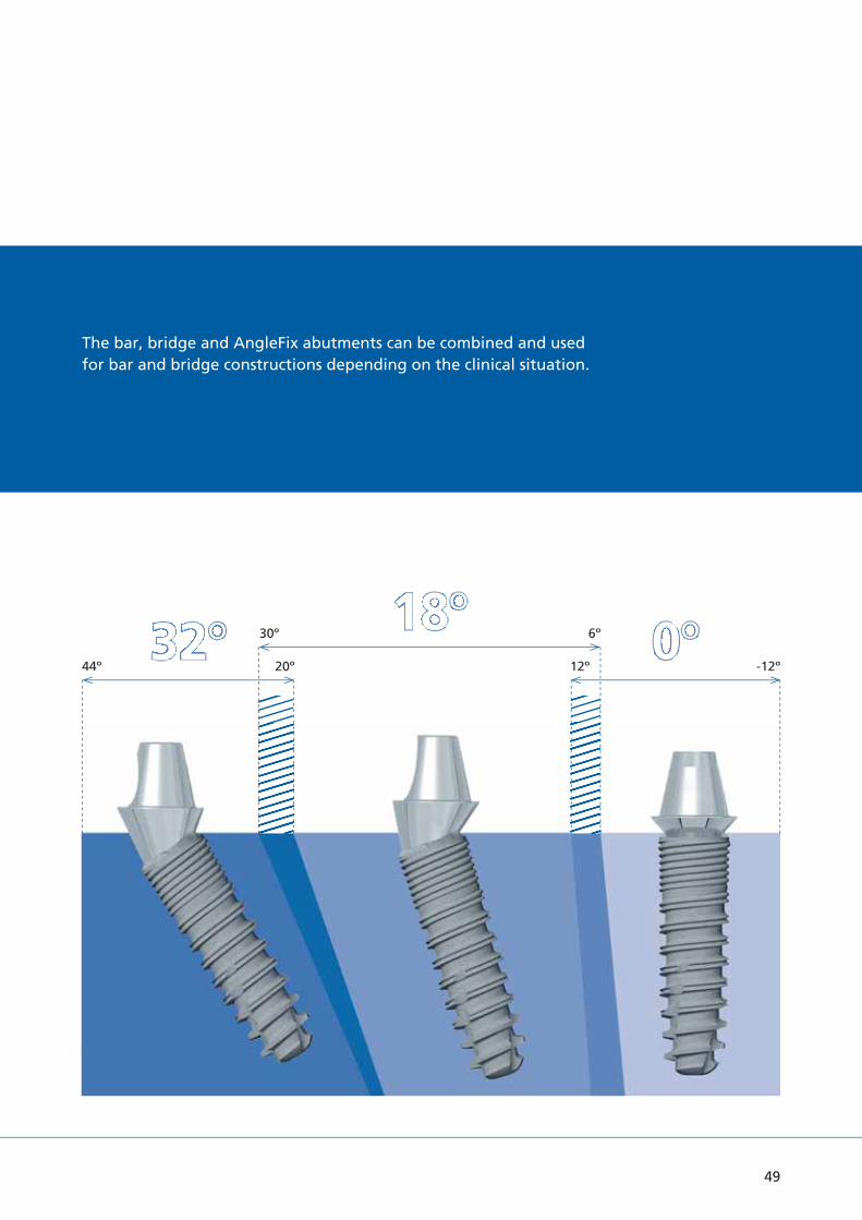
00ºº1818ºº3232ºº44º 20º 12º -12º
30º 6º
The bar, bridge and AngleFix abutments can be combined and used for bar and bridge constructions depending on the clinical situation.
49

Implant position.Before beginning treatment adequate vertical and horizontal bone, both in terms of quantity and quality, must be exposed, while paying particular attention to the position of the inferior alveolar canal and the mental foramen in the mandible and the maxillary sinus in the maxilla. A minimum clearance of 3.0 mm should be maintained to these critical anatomical structures.
To ensure adequate stability only tioLogic® implant types with the following dimensions should be used for the AngleFix system:
Dental technical variants.
Operator-removable restorations.
The tioLogic® implant types S ø 3.3 mm are available for patients with narrow alveolar ridges. Due to the small diameter and low load capacity (compared to the tioLogic® M ø 4.2 mm implants), these implants have a limited range of indications. In fully edentulous cases, four or more S ø 3.3 mm implants must be inserted with a splinted bar restoration without extension.
AngleFix restorations on tioLogic® implants require a minimum 11.0 mm implant length.
50

Implant aligned distally in the posterior region.
In order to achieve an accurate alignment of the angulated cone of the angled abutments the implants should be aligned so that when viewed distally the marking can be seen symmetrically on the placement aid or insertion aid.
First, the two anterior implants are inserted, whereby the paralleling posts can be used to aid parallel alignment.
When handling the AngleFix abutments, ensure that the occlusal screw is not damaged by tweezers etc.
The angulated AngleFix abutments have a larger
diameter than the implants. As part of the abutments may be below the bone line, the bone must be removed in this region, if required, so that the abutment sits correctly on the implant.
After fi xing the AngleFix abutments in position on the anterior implants, the corresponding angle gauge 18° or 32° is secured on the abutments according to the angular position given from the planning. The pin on the angle gauge functions as a parallel guidance aid for the pilot drill.
distal
AngleFix angle aid for 18° and 32°.
51

Fabricating the restoration.The AngleFix abutments are available for the series of abutments S, M and L in the straight and angulated (18° and 32°) versions. They are available for the straight abutments in a gingival height of 1.0 mm and in a gingival height of 2.5 mm for the angulated abutments.
The anterior implants are fi tted with straight abutments and the posterior region with Angle-Fix abutments in an angulation of 18° or 32° according to the implant positioning.
Titanium caps or plastic caps can be used forfabricating a restoration on AngleFix abutments. The AngleFix caps fi t on all three AngleFix series of abutments (S - M - L), as the fi tting surface of all AngleFix abutments and the cone (24°) are identical (ø 5.3 mm). They are secured in position on the AngleFix abutments using the AnoTite screw L 6.0 mm supplied.
Tightening torque AnoTite screw AngleFix abutment on the model: manually
AnoTite screw AngleFix abutment intra-orally: 30 Ncm
In the cases described the straight AngleFix abutment M 0° in the anterior and the angulat-ed AngleFix abutments with 32° angulation are used.
5.3 mm 5.3 mm 5.3 mm
1.0 mm
2.5 mm
4.0 mm 4.0 mm
2.5 mm
4.0 mm
24º 24º 24º
00ºº 1818ºº 3232ºº
AngleFix abutment M 0° GH 1.0 mm
AngleFix abutment M 18° GH 2.5 mm
AngleFix abutment M 32° GH 2.5 mm
Tightening torque Cap on AngleFix abutment on the model: manually
Cap on AngleFix abutment intra-orally: 25 Ncm
Working procedures.
Case 2: Plastic cap
Precious metal cap
Titanium cap
Case 1: Titanium cap
Plastic cap
Precious metal cap
Case 3: Scan cap AngleFix abutment
For restorations with temporary (case 1) or individually cast (case 2) or milled (case 3) AngleFix, the appropriate caps are secured on the AngleFix abutments:
The seating surface and cone (24°) for the caps on the AngleFix abutments is identical (ø 5.3 mm) for the S, M and L series of abutments. The same AnoTite screw, bridge abutment (L 6.0 mm) is used for all caps. The AngleFix abutment is placed with the bar, bridge, AngleFix abutment insertion key (secure the counter screw!).
Operator-removable restorations.
52

Lingual view of the model with shortened titanium caps on AngleFix abutments.Case 1: Temporary restoration.
The AngleFix titanium caps are secured in position on the AngleFix abutments using the AnoTite screw L 6.0 mm for fabricating a tempo-rary restoration.
The available space is checked using the lingual and palatal overcasts. If there is insuffi cient space available, the AngleFix titanium caps can be lightly and easily trimmed.
Titanium must not become overheated as this can lead to superfi cial hardening (alpha-case layer) and could complicate or handicap processing.
A wax set-up is then fabricated, which can be checked using the lingual and palatal overcasts.
Before waxing up the temporary restoration, ensure that there is an adequate, uniform cement gap between the AngleFix titanium caps and the temporary restoration by blocking out using preparation and casting wax (e.g.: Dentaurum REF 120-025-00). This guarantees a stress-free fi xation.
Finishing, trimming and polishing should be completed according to the instructions of the acrylic manufacturer.
PTFE cylinder pins are available for restorations which are bonded in the laboratory. The pins do not bond with the adhesive and prevent it getting into the screw aperture.
Model with blocked out titanium caps.
Poured temporary restoration with overcast.
5.6 mm
13.5 mm
AngleFix Titanium cap
3.2 mm
53

Working procedures.
Case 2: AngleFix long-term restoration.The AngleFix plastic caps are secured in position on the AngleFix abutments using the AnoTite screw L 6.0 mm.
The available space is checked using buccal and lingual overcasts. If there is insuffi cient space available, the AngleFix plastic caps can be lightly and easily trimmed.
A base structure is then fabricated as a strengthener for a long-term restoration. The wax-up is fabricated taking into consideration the lingual and palatal overcasts. This procedure guarantees that there is still suffi cient space for subsequent working stages and the pre-prosthetic planning can be maintained.
5.3 mm
12.0 mm
3.0 mm
AngleFix plastic cap
5.3 mm
CAD/CAM scan cap AngleFix
10.0 mm
Case 3: CAD/CAM manufacturingThe scan caps AngleFix are fi xed with the prosthetic screw L 6.0 mm on the AngleFix abutments.
After selecting the indication (here: AngleFix abutments) in the tioLogic® data set of the respective software, the scan caps AngleFix can be scanned.
The matching process and design are carried out according to the instructions of the software manufacturer and dental rules.
Operator-removable restorations.
54

Labial view of model with fi nished ceramic crowns.Firing the gingiva section in ceramic.
Milled zirconia framework.Framework design in CAD/CAM-Software.
Finished ceramic restoration on the AngleFix abutments.Bonding of the zirconium framework on the AngleFix caps.
55

56
Dental technical variants.
Telescopic restoration.Case: Precious metal abutments.Precious metal abutments are used for telescopic restorations. They are available for the S, M and L series of abutments and comprise a cast-on precious metal base, a plastic extension and an AnoTite screw. The precious metal abutments with their prefabricated precious metal bases guarantee high precision of fi t on the implant. The plastic extension allows the individual telescopes to be custom-designed.
Tightening torque Prosthetic screw, precious metal abutment on model: manually
AnoTite screw, precious metal abutment intra-orally: 30 Ncm
Precious metal abutments are positioned onto the laboratory implants and fi xed with the pros-thetic screws L 9.0 mm (observing the rotational stop). The space available is checked using the lingual overcast and palatal overcast and the acrylic extension is adapted accordingly.
Telescopic restoration
Ball abutment restoration
LOCATOR® restoration
Removable restorations.
Various types of removable prosthetic restoration are feasible:
Model with precious metal abutment in situ with overcast, oral view.
3.0 mm
3.7 mm
0.6 mm
11.4 mm
Precious metal abutment M, straight

57
The primary crowns are fabricated according to the space available within the overcasts. This procedure ensures that enough space is available for all further working steps, such as the fabrication of secondary crowns and the dimensions of the metal strengthener, as determined in the pre-prosthetic plan.
The waxed-up primary crowns are milled (e.g. using the milling machine Paramil 3, from Dentaurum). The crowns are placed onto the model, checked and then the sprues are applied. Before the objects to be cast are invested, the sub-gingival region is waxed in a conical shape. A precious metal alloy must be used to cast-on to the precious metal base.
Tip:The casting sprues are marked on the model according to their position.
Model with shortened precious metal abutment in situ and overcast model, labial view.
Model with parallel waxed precious metal abutment and overcast, oral view.
Model with sprued precious metal abutments.

58
Dental technical variants.
Removable restorations.
After having been cast, the primary telescope crowns are replaced onto the model and checked, fi nished and polished.
Model with cast precious metal abutment, without gingival mask, labial view.
Cast, trimmed precious metal abutment with overcast, labial view.
Cast precious metal abutment with gingival mask and secondary telescope crowns (electroformed caps), oral view.

59
In order to produce a long term, durable restoration, a metal strengthening structure is constructed to which each individual, electroformed secondary telescope is cemented.
Model with completely waxed strengthener, oral view.
Each primary telescope is marked for identifi ca-tion and to show its correct position on the implant, so that no mistakes are made during insertion
Model with precious metal abutment and metal strengthe-ner, labial view.
Model with marked precious metal abutment and metalstrengthener, labial view.
60
Dental technical variants.
Removable restorations.
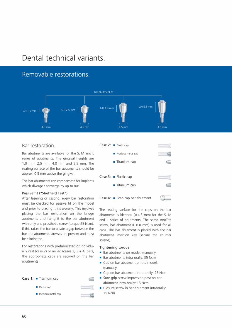
Bar restoration.Bar abutments are available for the S, M and L series of abutments. The gingival heights are 1.0 mm, 2.5 mm, 4.0 mm and 5.5 mm. The seating surface of the bar abutments should be approx. 0.5 mm above the gingiva.
The bar abutments can compensate for implants which diverge / converge by up to 80°.
Passive fi t (“Sheffi eld Test“).After lasering or casting, every bar restoration must be checked for passive fi t on the model and prior to placing it intra-orally. This involves placing the bar restoration on the bridge abutments and fi xing it to the bar abutment with only one prosthetic screw (torque 25 Ncm). If this raises the bar to create a gap between the bar and abutment, stresses are present and must be eliminated.
For restorations with prefabricated or individu-ally cast (case 2) or milled (cases 2, 3 + 4) bars, the appropriate caps are secured on the bar abutments.
GH 1.0 mm GH 2.5 mmGH 4.0 mm GH 5.5 mm
4.5 mm 4.5 mm 4.5 mm 4.5 mm
Bar abutment M
Case 2: Plastic cap
Precious metal cap
Titanium cap
Case 1: Titanium cap
Plastic cap
Precious metal cap
The seating surface for the caps on the bar abutments is identical (ø 4.5 mm) for the S, M and L series of abutments. The same AnoTite screw, bar abutment (L 6.0 mm) is used for all caps. The bar abutment is placed with the bar abutment insertion key (secure the counter screw!).
Tightening torque Bar abutments on model: manually Bar abutments intra-orally: 35 Ncm Cap on bar abutment on the model: manually
Cap on bar abutment intra-orally: 25 Ncm Sure-grip screw impression post on bar abutment intra-orally: 15 Ncm
Closure screw in bar abutment intraorally: 15 Ncm
Case 3: Plastic cap
Titanium cap
Case 4: Scan cap bar abutment

Case 1: Prefabricated bar(lasered or cast)Criteria for positioning a bar(bar attachment):
Horizontal bar positioning.To ensure that the masticatory forces are directed correctly, the bar must be positioned horizontally to the ideal occlusal plane. Tilting the bar would load the implants incorrectly and cause excessive pressure to be exerted on the mucous membranes.
Bar abutments on model with gingival mask, labial view.
Titanium caps on bar abutments on model, oral view.
Vertical bar positioning.With fi xed/free dentures, the bar attachment acts as an axis of rotation. To ensure that the alveolar ridges are loaded uniformly, the bar must be aligned at an angle of 90° to the bisection angle of the teeth.
Laser techniques, titanium caps.Depending on the impression technique, the prefabricated conical titanium caps should be secured on the bar abutments or bar laboratory implants with the enclosed AnoTite L 6.0 mm screw. They fi t all three bar abutments (S - M - L). The seating surface of all bar abutments is identical (ø 4.5 mm).
Horizontal bar positioning.
Vertical bar positioning.
Tita
nium
cap
, bar
4.5 mm
5.0 mm
3.0 mm
61

62
Dental technical variants.
Removable restorations.
The prefabricated titanium bars are shortened and fi xed in the correct horizontal axis for laser-welding with a parallelometer / fi xator (e.g. Paralas, Dentaurum).
The bar components and titanium caps are then lasered together. The only fi ller material which can be used is pure titanium wire (e.g. Dentaurum). Should further questions arise on lasering and processing titanium, please call the Dentaurum Hotline at: + 49 72 31 / 803 -410.
Shortened titanium bar with Paralas on the model.
Titanium bar with rider and retainer, occlusal view.
Trimmed titanium bar.
After laser-welding, the titanium bar should be trimmed and polished (e.g. with a Dentaurum rematitan® trimming set).
The titanium bar rider is then lasered to the titanium retainer and polymerized into the denture.

63
Casting, plastic caps.Depending on the impression technique, plastic caps or cast-on precious metal caps can be fi xed to the bar abutments or laboratory implant. They fi t all three bar abutments (S - M - L). The seating surface of all bar abutments is identical (ø 4.5 mm). Precious metal caps are processed in virtually the same manner as plastic caps – just the differences relevant to casting-on have to be taken into account (refer to section Dental tech-nical variants – Telescopic restorations). In this case, plastic caps were used.
Model with screw-retained plastic caps, labial view.
Model with shortened plastic caps, labial view.
Where space is at a premium, the plastic caps can be easily trimmed.
Model with plastic bar fixed in place, occlusal view.
A prefabricated plastic bar is waxed to the plastic caps.
Casting, trimming and polishing should be car-ried out according to the alloy manufacturer’s instructions. For the post-processing of the screw aperture respectively the screw seating, a countersink or cutter are available.
Model with fi nished precious metal bar, labial view.
4.5 mm
12.0 mm
3.0 mm
Plas
tic c
ap, b
ar

64
Case 2:Milled bar, plastic caps.Adhesive plastic caps, precious metal caps or titanium caps can be used on bar abutments for fabricating a milled bar. They fi t all three bar abutments (S - M - L). The seating surface of all bar abutments is identical (ø 4.5 mm). They are secured on the bar abutments with the enclosed prosthetic screw L 6.0 mm.
Model with shortened plastic caps on bar abutments, oral view.
Model with plastic bar secured in position and palatal overcast, labial view.
Palatal view of model with plastic caps on bar abutments and overcast, oral view.
Dental technical variants.
Removable restorations.
In this case, plastic caps were used. Precious metal caps are processed in virtually the same manner as plastic caps – just the differences relevant to casting-on have to be taken intoaccount (refer to section Dental technical variants – Telescopic restorations). The process-ing of titanium caps for bonding is explained on p. 67.
If there is insuffi cient space available, the plastic caps can be lightly and easily trimmed.
The plastic caps are bonded to the acrylic.

65
Model with milled bar pattern, labial view.
Following this, the pattern for the individual bar is fabricated and paralleled with a milling machine.
Model with milled bar pattern and overcast, oral view. Model with cast and fi ne-milled bar, labial view.
Model with cast bar, labial view.
4.5 mm
0.6 mm
11.4 mm
Prec
ious
met
al c
ap, b
ar
3.0 mm
4.5 mm
12.0 mm
3.0 mm
Plas
tic c
ap, b
ar

66
For enhanced retention, horizontal and vertical attachments are integrated.
Trimmed bar with attachment parts, labial view.
Trimmed bar with overcast and attachment parts, oral view.
Casting, trimming and polishing must be carried out according to the manufacturer’s in-structions. After casting, the reamer is used for fi nishing the screw aperture, the countersink is used for the screw seat and the cutter for the seating surface of the plastic cap.
The attachments are then placed in position.
In this case the restoration is fabricated with an electroplated mesostructure. For static reasons, this is provided with a chrome cobalt strength-ener (e.g. Dentaurum, remanium® GM 800+).
Dental technical variants.
Removable restorations.
Mesostructure, basal view.
Finished case without denture, labial view.

67
Case 3:Milled bar, titanium caps for adhesive technique.Adhesive titanium caps are available for adhering cast bars intra-orally. They fi t all three bar abutments (S - M - L). The seating surface of all bar abutments is identical (ø 4.5 mm). Adhering the titanium caps can compensate for imprecise casting and possible differences during impression-taking or model casting.
3 adhesive titanium caps and a plastic cap with overcast, oral view.
3 adhesive titanium caps on bar abutment on model, labial view.
With restorations supported on four implants, adhesive titanium caps are secured on three bar abutments with an AnoTite L 6.0 mm screw. These three act as adhesive bases.
Either a plastic cap or a precious metal cap is fi xed to the fourth bar abutment. In this case a plastic cap was selected.
Tita
nium
cap
, bar
4.5 mm
5.0 mm
3.0 mm
4.5 mm
12.0 mm
3.0 mm
Plas
tic c
ap, b
ar
Model with plastic bar fi xed in place, oral view.

68
conditioned according to the adhesive manu-facturer’s instructions. The inner hex of the AnoTite screw must be sealed with wax.
Model with adhered / screw-retained bar, labial view.
Prior to bonding, the contact surfaces of the titanium caps and the inner aspects of the bar must be provided with additional retention and
Cast bar and titanium caps for adhering to bar abutments, labial view.
Dental technical variants.
Removable restorations.
The titanium caps and plastic caps are bonded together with acrylic. The screw in the plastic cap must be loosened before raising the pattern. This screw keeps the cast bar in place during bonding. The following steps for cast bars are the same as described for case 2 (milled bar).
Milled plastic bar, basal view.
Once the adhesive has been mixed, it is applied to both contact surfaces of the three connectors, the cast bar placed intra-orally and the cast plastic cap fi xed over the guide screw.
To ensure that the prosthetic screws can be loosened easily, any excess adhesive above them must be removed before it hardens. Once the adhesive has hardened, all prosthetic screws should be loosened and all other excess adhesive removed. The cast bar is then replaced on the model before processing the restoration further.

69
Case 4: CAD/CAM manufacturingThe scan caps bar are fi xed with the prosthetic screw L 6.0 mm on the bar abutments.
After selecting the indication (here: bar abutments) in the tioLogic® data set of the re-spective software, the scan caps bar can be scanned.
The matching process and design are carried out according to the instructions of the software manufacturer and dental rules.
4.5 mm
CAD/CAM scan cap bar
10.0 mm

70
Ball abutment restoration.Ball-anchored dentures are implant-borne, mucosa-supported. When using ball abutments existing coverdentures can be used as temporary dentures or modifi ed with a chrome cobalt framework – alternatively a new coverdenture can be fabricated. Ball anchors function in such a manner that it is advisable to support the denture on two implant abutments. The implants must not diverge / converge by more than 20°. Ball head with Matrix, Dalbo®-Plus.
Ball head in situ.
Dental technical variants.
Removable restorations.
Care should be taken to avoid an excessive mechanical loading when using ball head abutments together with ø 3.3 mm implants.
The ball abutment is available in gingival heights of 1.5 mm, 3.0 mm and 4.5 mm for S, M and L abutments. The gingival height is the distance between the uppermost edge of the implant and the lowermost edge of the hex of the ball abutments.
This lower edge should be placed approx. 1.0 mm above the gingival line. To achieve optimum re-tention, all ball abutments should be positioned at the same level. The ball is 2.25 mm in diame-ter. The components of the ball abutment may not be modifi ed. Only the matrix withdrawal force can be adjusted by activating the inner matrix. The ball abutment is placed with the ball abutment insertion key.
Matrices.The withdrawal force of the matrix Dalbo®-PLUS can be adjusted to suit the individual patient. Through rotational movements by means of a screwdriver for the matrix Dalbo®-PLUS, the lamellae are activated or deactivated. If neces-sary, the inner matrix can be replaced as well with the screwdriver.
Tightening torque Ball abutment on a model: manually Ball abutment intra-orally: 35 Ncm
10.0 mm
2.25 mm
Ball head laboratory implant
3.5 mm
3.0 mm
10.0 mm
2.25 mm
Ball abutment
1.5 / 3.0 / 4.5 mm
3.6 mm
Dalbo®-Plus Matrix
3.1 mm

71
Working procedures (direct / indirect).The direct technique involves processing the matrix into an existing denture directly in the patient’s mouth without fabricating a model (case 1). Neither an impression post nor a laboratory implant are required.
The indirect technique requires an impression and a model. The matrix is processed into the denture in the laboratory (case 2).
Case 1 direct version.The ball abutments are attached to the implants intra-orally. During the clinical procedures, the undercuts should be protected with a rubber dam. It is formed over the matrix to prevent cold-curing resin fi lling the undercuts in the mouth which would prevent the denture being removed after the resin has cured. Please adhere strictly to the resin manufacturer’s instructions.
Case 2 indirect version.Impression.With the indirect version, the impression can not only be taken using the closed technique described in the section Impression – Closed impression technique (page 28), but also directly over the ball abutments fi xed in the mouth. The correct ball abutments for the gingival height and S, M or L abutment should be selected, the closure screws or gingiva formers removed and the ball abutments secured in the implants. Impression material is applied around all ball abutments, the closed impression tray loaded with impression material and the impression taken. As soon as the impression material has set, the tray can be removed. Ensure that the impression has captured the ball abutments exactly.
The ball laboratory implant is then repositioned in the impression in the laboratory. The fl at surfaces beneath the ball ensure that the implant axes are transferred precisely. The model is then fabricated as described in the section Casting the model – Closed impression technique. A ball laboratory implant is available for all series of abutments as all balls have a diameter of 2.25 mm.
In this case a closed putty / wash impression was taken over the ball abutments.

72
Laboratory.In the laboratory the ball laboratory implants are repositioned in the impression and the model fabricated.
The matrices are placed over them and their angle of insertion aligned parallel and axially to one another.
Dental technical variants.
Removable restorations.
Ball abutment screwed in.
Ball abutment with matrix Dalbo®-Plus.
Blocking out the undercuts prior to polymerizing.
In order to protect the balls against acrylic seeping in and ensure that the matrices areparallel with the angle of insertion, the undercuts must be blocked out with wax.
Opening in the denture for fi nishing.
The denture must be relieved adequately above the ball abutments to allow suffi cient clearance for the matrices. To permit the matrices to be checked for exact fi t, an opening should be drilled in the lingual or palatal aspect of the denture.

73
The matrix polymerized into the denture: basal view.
Cold-curing resin is applied through the opening to secure the matrices in the denture. The instruc-tions for the resin should be adhered to strictly. Once the resin has cured, the denture is removed from the model. The excess resin on the lower margins of the matrices must be removed before smoothing and polishing the denture.
Finished case with ball abutments.
The balls should be checked for correct function-ing on the working model.
A new full denture is fabricated using exactly the same procedures except that the matrices are processed into the denture base.
Recall appointment.Dentures and their retention units must be examined at six-monthly intervals. The following points, inter alia, must be taken into account:
Eliminate unfavorable movements of the denture (reline the denture to optimize it, activate or replace the matrices)
Check the fi t of the ball abutments on the implant (tighten if necessary)
Oral hygiene (remove plaque and calculus and, if necessary, re-instruct the patient on cleaning implants)

74
LOCATOR® restoration.The LOCATOR® technique is for fabricating im-plant-borne, membrane-supported restorations with a very low overall height. Existing coverdentures can be modifi ed or remade. The LOCATOR® can be used for membrane-supported coverdentures with two to four implant abutments. The intermaxillary space should be at least 4.0 mm. Special retainers (green and red) compensate for diverging / converging implants of up to 40° (not applicable to tioLogic® implants S ø 3.3 mm). LOCATOR®
components must not be modifi ed. Only the withdrawal forces of the LOCATOR® matrices can be adjusted as required using the exchangeable retention inserts.
LOCATOR® abutment.LOCATOR® abutments are available for S, M and L abutments in gingival heights of 1.0 mm, 2.0 mm, 3.0 mm; 4.0 mm and 5.0 mm. The gingival height refers to the cylindrical section of the LOCATOR® abutment. Its upper edge should be placed approx. 1.0 mm above the gingival line. The head with retainer is identical for all LOCATOR® abutments. The LOCATOR®
abutment is inserted with the LOCATOR®
insertion key.
LOCATOR® matrices.The LOCATOR® matrix comprises a metal base with inner retention insert. It is for polymerizing into an existing or new coverdenture.
The withdrawal force of the LOCATOR® matrix is regulated with an exchangeable retention insert which is available in the following versions:
transparent (medium) pink (low) blue (very low) green (increased extension) – not for use with tioLogic® implants S ø 3.3 mm
red (increased angulation) – not for use with tioLogic® implants S ø 3.3 mm
The LOCATOR® matrix is supplied with a black retention ring inserted (polymerizing in), a white spacer ring (blocking out undercuts) and the de-fi nitive retention rings in transparent, pink and blue.
The retention inserts of LOCATOR® matrices can be exchanged with the LOCATOR® retentionkey. To do so, the pointed section of the LOCA-TOR® retention key is pressed into the lower side corner of the retention insert which is then pulled downwards and out.
Dental technical variants.
Removable restorations.
5.5 mm
LOCATOR® matrix
2.25 mm
LOCATOR® abutment M
1.0 / 2.0 / 3.0 / 4.0 / 5.0 mm

75
The new retention insert is inserted into the empty metal housing by exerting fi rm pressure with the pressing tool on the LOCATOR® reten-tion key. The retention insert must be felt to click in and come to rest fl ush with the lower edge of the metal housing.
The LOCATOR® angle measuring post and the LOCATOR® angle measuring device are used for determining the divergence to the pillars / posts.
Tightening torque LOCATOR® abutment on the model: manually LOCATOR® abutment intra-orally: 30 Ncm
Working procedures (direct / indirect).The direct technique involves processing the LOCATOR® matrix into an existing denture directly in the patient’s mouth without fabricat-ing a model (case 1). Neither an impression post nor a laboratory implant are required.
The indirect technique requires an impression and a model. The LOCATOR® matrix is processed into the denture in the laboratory (case 2).
Case 1: direct version.The appropriate LOCATOR® abutments (S, M or L) are secured on the appropriate implants intra-oral-ly. The LOCATOR® matrices are processed into the coverdenture with cold-curing resin in the mouth. The instructions for the resin should be adhered to strictly.
Case 2: indirect version.Inserting LOCATOR® abutments.The matching LOCATOR® abutment for the gingival height and S, M or L abutment series should be selected. The closure screws or gingiva formers are removed and the LOCATOR®
abutment secured on the appropriate implant.
Taking an impression over LOCATOR®
abutments.Apart from the open impression technique on implants described on p. 74, the impression can also be taken over LOCATOR® abutments fi tted in the mouth.
This involves plugging a LOCATOR® impression cap (black inner retention insert) onto every LOCATOR® abutment. This must be felt to click into place.
Impression material is then applied around all LOCATOR® abutments and the closed impression tray loaded with impression material which is allowed to set before removing the impression. Ensure that the LOCATOR®
impression cap isseated precisely.
5.2 mm
LOCATOR®
laboratory implant
10.0 mm
LOCATOR® impression cap
4.4 mm

76
Laboratory.In this case, the impression was taken over the LOCATOR® abutments with the LOCATOR®
impression caps and an existing denture modifi ed.
In the laboratory the LOCATOR® laboratory im-plant is inserted into the LOCATOR® impression cap and checked for precise fi t. The model is fabricated as described in the section Casting the Model – Closed impression technique, page 28. One single LOCATOR® laboratory implant is available for S, M and L series abutments as the head and retainer of all LOCATOR® abutments are identical.
Dental technical variants.
Removable restorations.
On the model a white spacer ring is placed on every LOCATOR® abutment. This prevents resin fl owing beneath the matrices while polymerizing the LOCATOR® matrices into the denture. TheLOCATOR® matrices (black inner retention inserts) are then plugged onto the LOCATOR®abutments. These must be felt to click into place.
The denture must be relieved above the LOCATOR® abutments to provide adequate clearance for the LOCATOR® matrices. To permit the LOCATOR® matrices to be checked for exact fi t, an opening should be drilled in the lingual or palatal aspect of the denture.
Cold-curing resin is applied through the opening to secure the LOCATOR® matrices in the denture. The instructions for the resin should be adhered to strictly.
Once the resin has cured, the denture is removed from the model. The excess resin on the lower margins of the LOCATOR® matrices must be re-moved before smoothing and polishing the den-ture.
Model with LOCATOR® laboratory implants and gingival masks, labial view.
LOCATOR® matrices on implants with LOCATOR® spacer ring, labial view.
Denture on model with openings above the LOCATOR®
matrices, oral view.
5.2 mm
LOCATOR® angled measuring post
8.0 mm
LOCATOR® measurement guide
15.3 mm
50.8 mm

77
The black retention inserts are removed using the LOCATOR® retention key and the desired transparent, pink, blue, green or red retention insert slipped in (green and red are not for use with S ø 3.3 mm implants).
The LOCATOR® matrices must be checked for correct functioning on the working model.
Placement.The LOCATOR® matrices must be checked for correct functioning in the patient’s mouth.If a new full denture is being fabricated, the procedure is virtually identical – except that the matrices are processed into the acrylic denture base.
Temporary restoration.If a new denture is being fabricated, the existing denture should be relieved around the LOCATOR® abutments and soft-lined.
Recall appointment.Dentures and their retention units must be ex-amined at six-monthly intervals. The following points, inter alia, must be taken into account:
Eliminate unfavorable movements of the denture (reline the denture to optimize it, activate or replace the retention elements)
Check the fi t of the LOCATOR® abutments on the implant (tighten if necessary)
Oral hygiene (remove plaque and calculus and re-instruct the patient on cleaning implants)
LOCATOR® matrices polymerized into the denture, basal view.
Finished denture with model.

78
The tioLogic® range of products includes precision instrumentsand selection aids for dental technicians. This simplifies prosthetic procedures even more.
Handhold AnatomicHold For gripping the polishing aids and holders.
Polishing aidS, M and L
For gripping denture sections during trimming and polishing; made of titanium to withstand long periods of use under the infl uence of rotary instruments.
Ceramic abutment holderS, M and L
For gripping ceramic abutments during processing, rotationally stable.
Handhold AnatomicTwist For gripping and controlled rotation of theinstrument sets.
Milling cutter,diamond-coated (bar abutment)
Reworking the basal surfaces ofcast plastic bar caps.
Countersink – Screw seat Tungsten carbide for trimming the screw seat precisely.
Precision instruments / Selection aids.
Technical information.

79
Drill for guide sleeve Pre-drill for pre-drilling in the surgical stent.
Dalbo®-Plus torque key For adjusting the withdrawal force of the Dalbo®-Plus matrix.
LOCATOR® retention key Pointed tool for replacing the retention insert in LOCATOR® matrices. Pressing tool for inserting a new retention insert into an empty LOCATOR®
metal housing.
Selection aid set S, M and L Set containing plastic reproductions of the most important abutments such as titanium and bar abutments. For evaluating the gingival height and total height prior to ordering the abutments.
S - M - L test sleeves for checking the abutment line of a tioLogic® abutment (begin with test sleeve S).

80
Technical information.Data, abutments.
For example, the M series of abutments
Guide sleeve, titaniumL 6.0 mm
6.0 mm
2.1 mm5.0 mm
Guide sleeve, titaniumL 10.0 mm
10.0 mm
2.1 mm5.0 mm
X-ray reference sphere
5.0 mm
Gingiva former M,conical
1.5 / 3.0 / 4.5 / 6.0 mm
5.0 mm
Gingiva former M,cylindrcal
1.5 / 3.0 / 4.5 / 6.0 mm
3.7 mm
Temporary abutment M
13.5 mm
3.0 mm
5.0 mm4.0 mm
Screw fortemporary abutment
13.5 mm
2.7 mm
Impression post M,open, incl. screw
14.0 mm
Screw,for impression post,open
25.0 mm
Impression post M,open, incl. screw
10.0 mm
Screw,for impression post,open
20.0 mm
Impression post M,closed
7.0 mm
Impression cap M
6.0 mm
Bite registration cap M
6.0 mm
Laboratory implant M
12.0 mm

81
For example, the M series of abutments
Scan abutment M
12.0 mm
CAD/CAM titanium bloc M, PreForm
19.9 mm19.9 mm
1.5 mm
CAD/CAM titanuimbase M
0.6 mm
3.5 mm
Precious metalabutment M,cast on
11.4 mm
3.0 mm
0.6 mm
3.7 mm
Titanium abutment M,straight
6.0 mm
4°
1.0 / 2.5 / 4.0 mm
2.8 mm
Titanium abutment M,angled
6.0 mm
1.5 / 3.0 mm
20°
Titanium abutment M,adjustable,anatomical
9.5 mm
2.5 mm
3.8 mm3°
Titanium abutment M,adjustable,cylindrical
9.5 mm 2.5 mm
5.8 mm
Bar abutment M
1.0 / 2.5 / 4.0 / 5.5 mm
4.5 mm
Impression post, barincl. screw
10.0 mm
Screwimpression post, bar
16.0 mm
Laboratory implant, bar
10.0 mm
Titanium cap, bar
5.0 mm
4.5 mm3.0 mm
Titanium cap, bar,adhesive technique
5.0 mm
4.5 mm3.0 mm
Precious metalabutment, bar
11.4 mm
4.5 mm3.0 mm
0.6 mm
Plastic cap, bar
12.0 mm
4.5 mm3.0 mm
Scan cap, bar
10.0 mm
4.5 mm
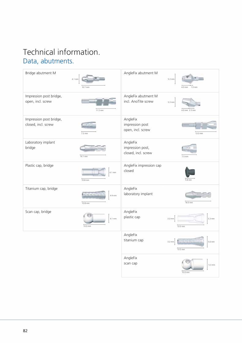
82
Technical information.Data, abutments.
AngleFix abutment M
1.0 mm
5.3 mm
4.0 mm
AngleFix abutment Mincl. AnoTite screw
2.5 mm
5.3 mm
4.0 mm
AngleFiximpression postopen, incl. screw
13.0 mm
AngleFiximpression post,closed, incl. screw
7.5 mm
AngleFix impression capclosed
5.8 mm
AngleFixlaboratory implant
16.0 mm
AngleFixplastic cap
13.5 mm
5.3 mm3.3 mm
AngleFixtitanium cap
13.5 mm
5.6 mm3.2 mm
AngleFixscan cap
10.0 mm
5.3 mm
Bridge abutment M
4.1 mm
10.7 mm
Impression post bridge,open, incl. screw
11.5 mm
Impression post bridge,closed, incl. screw
7.5 mm
Laboratory implantbridge
14.1 mm
Plastic cap, bridge
10.8 mm
4.1 mm
Titanium cap, bridge
10.8 mm
4.4 mm
Scan cap, bridge
10.0 mm
4.1 mm

83
For example, the M series of abutments
AnoTite screwL 9.0 mm
m
M 1.6
AnoTite screw,bar, AngleFix,L 6.0 mm
6.0 mm
M 1.62.2 mm
For example, the M series of abutments
Ball abutment M
1.5 / 3.0 / 4.5 mm
2.25 mm
Matrix Dalbo®-PLUS
3.6 mm
3.1 mm
Ball laboratory implant
10.0 mm
2.5 mm
2.25 mm
LOCATOR® abutment M
1.0 / 2.0 / 3.0 / 4.0 / 5.0 mm
LOCATOR® matrix
2.25 mm
5.5 mm
LOCATOR®
impression cap
4.4 mm
5.3 mm
LOCATOR®
Laboratory implant
10.0 mm
5.2 mm

84
Description.The torque ratchet is a precision instrument that can be disassembled. To ensure that it always functions perfectly, the torque ratchet should be disassembled, cleaned, disinfected and lubricated and then sterilized after reassembly in accordance with the instructions for use (p. 89 torque ratchet) before using for the fi rst time and immediately after each use.
It is important to read the instructions for use carefully and check the function of the torque ratchet before each use to ensure the precision of the torque. The torque ratchet should make a uniform sound when functioning properly; the ratchet head should not be blocked. After use, the tension of the torque ratchet spring should be released by loosening the adjusting screw. The torque ratchet should be recalibrated annually.
Accuracy of the torque ratchet according to manufacturer + / - 10 %.
Torque ratchet.

85
Use.The torque ratchet can be used for the surgical procedure, implant insertion, securing the closure screws, gingiva formers and impression posts and for temporary and permanent prosthetic restorations. Different inserts are available depending on the application (p. 86).
The ratchet is set to the required torque using the adjusting screw. To set the correct torque, the adjusting screw is turned clockwise to the required torque line.
The torque ratchet is additionally provided with a block function. To set the block function, turn the adjustment screw to the ‘∞’ symbol. Do not turn too tightly! For storage, turn the torque adjustment screw back until the spring is as relaxed as possible!
The pressure point for exact torque release is on the head of the torque adjustment screw. When the adjusted torque has been reached, the scale sleeve will bend around the axis in the ratchet head. The release is audible and perceptible. After the torque release, do not apply more pressure; this could damage the ratchet. When you let go of the torque adjustment screw, the ratchet returns to its initial position.
Exceeding the torque specifi ed by Dentaurum Implants can cause mechanical damage to com-ponents, the implants, and destruction of bony structures.
The block function mode should be used with ext-reme caution. After use the value must be reset to standard torque to prevent mistakes next time it is used.
The word ‘IN’ on the ratchet head shows that the ratchet is in the correct tightening position. The word ‘OUT’ stands for loosening the torque.
When fi tting the permanent prosthetic restorati-on, all prosthetic screws should be tightened with the torque ratchet set at the relevant torque (p. 87 table for torque ratchet settings) and then re-tightened after approx. 5 minutes using the same torque. It is important that the insertion key fi ts fl ush in the prosthetic screw. We recommend using a new AnoTite prosthetic screw for the fi -nal fi tting.
∞

86
Torque ratchet.
Overview – Inserts for the torque ratchet.Depending on the application there are different inserts available.
Hex key SW 1.3– ratchet, L 26.0 mm.
Hex key SW 1.3– ratchet, L 16.0 mm.
Hex key SW 2.5– ratchet, L 23.0 mm.
Hex key SW 2.5– ratchet, L 13.0 mm.
Hex key SW 2.5– ratchet, L 8.0 mm.
Insertion keyball abutment ratchet,L 15.0 mm.
Insertion keyLOCATOR® abutment,L 15.0 mm.
Insertion key bar/bridge/AngleFix abutment ratchet,L 16.0 mm.
Adapter – ISO shankhexagon / ratchet.

87
Table – Tightening torques for implants and prosthetic components.*The torque ratchet is only intended for clinical use. Prosthetic screws should be tightened manually in the laboratory.
Implant (depending on the bonedensity) max. 40 Ncm
Closure screwsImplant
15 Ncm or manually
Closure screwsbar abutment
15 Ncm or manually
Closure screwsbridge abutment
15 Ncm or manually
Closure screwsAngleFix abutment
15 Ncm or manually
Gingiva former 15 Ncm or manually
Screw forimpression post
15 Ncm or manually
Screw fortemporary abutment
15 Ncm or manually
AnoTite screw9.0 mm
30 Ncm
Bar abutment 35 Ncm
Bridge abutment 35 Ncm
AngleFix abutment 0ºGH 1.0 mm
35 Ncm
Bar, bridge, AngleFixAnoTite screwL 6.0 mm
25 Ncm
Ball abutment 35 Ncm
LOCATOR® abutment 30 Ncm
* primary stable and osseointegrated

88
Torque ratchet.
Torque ratchet.Disassembling.Completely loosen torque adjustment screw ➄and remove the spring ➃. Pull ratchet head ➁
with the threaded rod from the scale sleeve ➂.
Removing ratchet wheel
Pull back the pin ➅ in the direction of the arrow using your thumb and index finger and remove the ratchet wheel ➀.
Ratchet head, assembled. Ratchet head, disassembled. Never loosen these screws as the ratchet will lose its torque function.
Blocking function – „∞“ mark.
∞

89
Sterilization.The instrument must be sterilized with steam at 134 °C / 273 °F for 18 min.
Apply the regulations in force in the country where the torque wrench is used.
Before sterilization, the torque ratchet must be completely assembled and set to the lowest torque.
Sterilize the key according to cycles of sterili-zation recommended by the manufacturer of the autoclave. We recommend the use of devices equipped with a vacuum pump (type B) to decrease the risk of formation of air pockets.
We advise against the use of a hot air sterilizer because it can lead to ageing of the spring and subsequently bring about a change of the torque value. Find more information on the preparation of medical devices at www.rki.de or www.a-k-i.org.
Assembling.To assemble the torque ratchet correctly, connect the components in the following order: first remove the pin ➅ as described above and insert the ratchet wheel ➀.
Note: To avoid mistakes, the ratchet wheel ➀can only be inserted on one side.
Lubricating points ( )
Lubricate the areas marked with the drop symbol with care oil for handpieces. Then assemble the ratchet components as described below and perform a function test.
Slide the spring ➃ over the torque adjust-ment screw ➄. Pass the ratchet head ➁ with the threaded rod through the scale sleeve ➂
and screw to torque adjustment screw ➄.
After assembly and before each use, check the correct function of the torque ratchet. If there is an audible regular ratchet noise and the mechanism of the torque limit functions, the instrument is functioning correctly.
➀ Ratchet wheel
➂Scale sleeve
➆Scale
➇Washer
➃ Spring
➄Torque adjustment screw
Ratchet latch Threaded rod Joint
➁ Ratchet head
➅ Pin

90
Pure titanium DIN EN ISO 5832-2
Chemical composition (% by mass) O 0.4 % max.
Fe 0.5 % max.
C 0.1 % max.
N 0.05 % max.
H 0.012 % max.
Ti Residue
Physical and mechanical properties 0.2 % yield strength 520 MPa min
Tensile strength 680 MPa min
Elongation at rupture 10 % min.
Titanium alloy DIN EN ISO 5832-3
Chemical composition (% by mass) AI 5.5 % – 6.75 %
V 3.5 % – 4.5 %
Fe 0.3 % max.
C 0.08 % max.
N 0.05 % max.
H 0.015 % max.
O 0.2 % max.
Ti Residue
Physical and mechanical properties 0.2 % yield strength 780 MPa min.
Tensile strength 860 MPa min.
Elongation at rupture 10 % min.
Technical information.Material composition.

91
Precious metal alloy
Chemical composition (% by mass) Au 60 %
Pt 19 %
Pd 20 %
Ir 1 %
Physical and mechanical properties Density 17.5 g / cm3
Melting range 1400 °C – 1490 °C
Tensile strength > 750 MPa
Hardness > 215 HV5
0.2 % yield strength > 650 MPa
Modulus of elasticity 136 GPa
Elongation at rupture > 2%
CTE 25 – 500°C 11.9 x 10⁻⁶ K-1
CTE 25 – 600°C 12.2 x 10⁻⁶ K-1
Condition 15 – 75 % KV
Precious metal abutment S approx. 0.307 g
Precious metal abutment M approx. 0.359 g
Precious metal abutment L approx. 0.482 g
Precious metal cap, bar approx. 0.260 g
PEEK
Chemical composition (% by mass) Thermoplastic high-perfor-mance polymer
Physical and mechanical properties Yield strength 95 MPa
Elongation > 25 %
Modulus of elasticity 4.2 GPa
Operating temperature 260 °C / 300 °C (continuous / temporary)

92
Safety instructions.
ManufacturerDentaurum Implants GmbH I Turnstr. 31 75228 Ispringen I Germany
restoration should take into account the particular oral situation to avoid overloading the components.Using tioLogic® implant system components in combination contrary to the instructions for use / manuals and which are not described as being specifi cally combinable, can also cause mechanical failure, damage to the tissue or unsatisfactory aesthetic results.tioLogic® implant types are not known to have any side effects or produce any interaction at the time of going to press. It cannot, however, be ruled out that in rare cases reactions to components used in the materials of the tioLogic® implant system may occur or that there may be electrochemically-induced discomfort.
Application, availability, precautions, documentation.The tioLogic® product range is supplied exclusively to doctors, dentists and dental technicians. It should only be used by doctors, dentists or dental technicians who are familiar with dental implantological procedures, including diagnosis, preoperative planning, surgical technique and prosthetic treatment.
Before use, operators should ensure that they have carefully read and understood the full tioLogic® instructions for use / manuals.
Brief description.tioLogic® implants are designed for insertion in the endosteal region of the maxilla or mandible. Depending on the indication, corresponding transgingival abutments are secured on the im-plants and fi tted with a prosthetic superstruc-ture. The tioLogic® implant system contains specially coordinated instruments, abutments and accessories for placement of the implants and fabrication of the prosthetic restoration. Only original components of the tioLogic® implant system should be combined in accordance with the instructions for use / user manuals.
Further informationThough placement of dental implants has a high rate of success and implants have a high survival rate, successful treatment cannot be guaranteed. The operator should note and document any problem cases and inform the manufacturer Dentaurum Implants. An inadequate number of implants, implants with insuffi cient length or diameter, unfavorable positioning of the implants or a statically poor prosthetic restoration can cause premature implant loss and fatigue fractures in implants, abutments and prosthetic screws under biomechanical loading. Placement of the implants and fabrication of the prosthetic

93
SA
FET
Y
As the instructions and manuals cannot provide all information for immediate use, we strongly recommend that, before using the system, operators attend a tioLogic® system training course offered by Dentaurum Implants to learn the correct techniques.
Refer to the Product Catalog and the Surgery Manual for information on precautions and the selection of components for the surgical procedure.
Refer to the Product Catalog and the Prosthetic Manual for information on precautions and the selection of components for the prosthetic procedure.
Before using this product, the operator must give the patient a thorough examination and a detailed explanation of the product. Dentaurum Implants recommends full clinical, radiological, photographic and statistical documentation.
The tioLogic® implant system components can be documented, e. g. in the patient fi le or PatientPass, (REF 989-961-10) using the additional labels.
The operator should ensure the products cannot be aspirated during intra-oral use.Not all components are available in every country.
Quality, warranty and liability.Development, clinical testing, production and quality control of the tioLogic® product range are completed in accordance with the Medical Device Directive 93/42/EEC.Sections 9 and 10 of our General Terms of Delivery and Payment apply with regard to warranty or liability – unless stated otherwise in the Instructions for Use / Manual.Warranty and liability are rendered void in particular if the products are not used by the operator or a third party in accordance with the instructions for use; this also applies if the tioLogic® product range is used in combination with products from other manufacturers, which have not been specifi cally recommended for use by Dentaurum Implants. Dentaurum Implants has no control over processing and application of the product. These are the sole responsibility of the user.

989-
960-
20
Prin
ted
by D
enta
urum
G
erm
any
06
/19/
C/R
1-7
Turnstr. 31 I 75228 Ispringen I Germany I Phone + 49 72 31 / 803 - 0 I Fax + 49 72 31 / 803 - 295www.dentaurum-implants.com I [email protected]
DENTAURUMQUALITYWORLDWIDEUNIQUE
Dentaurum GroupGermany I Benelux I España I France I Italia I Switzerland I Australia I Canada I USA and in more than 130 countries worldwide.
For more information on our products and services, please visit www.dentaurum.de
Date of information: 06/19
Subject to modifi cations
Like us on Facebook! Visit us on YouTube! Follow us on Pinterest!
www.dentaurum.com