Embed Size (px)
Citation preview
BA00292F/00/EN/13.12
71164419
Valid as of software version
V02.01.00
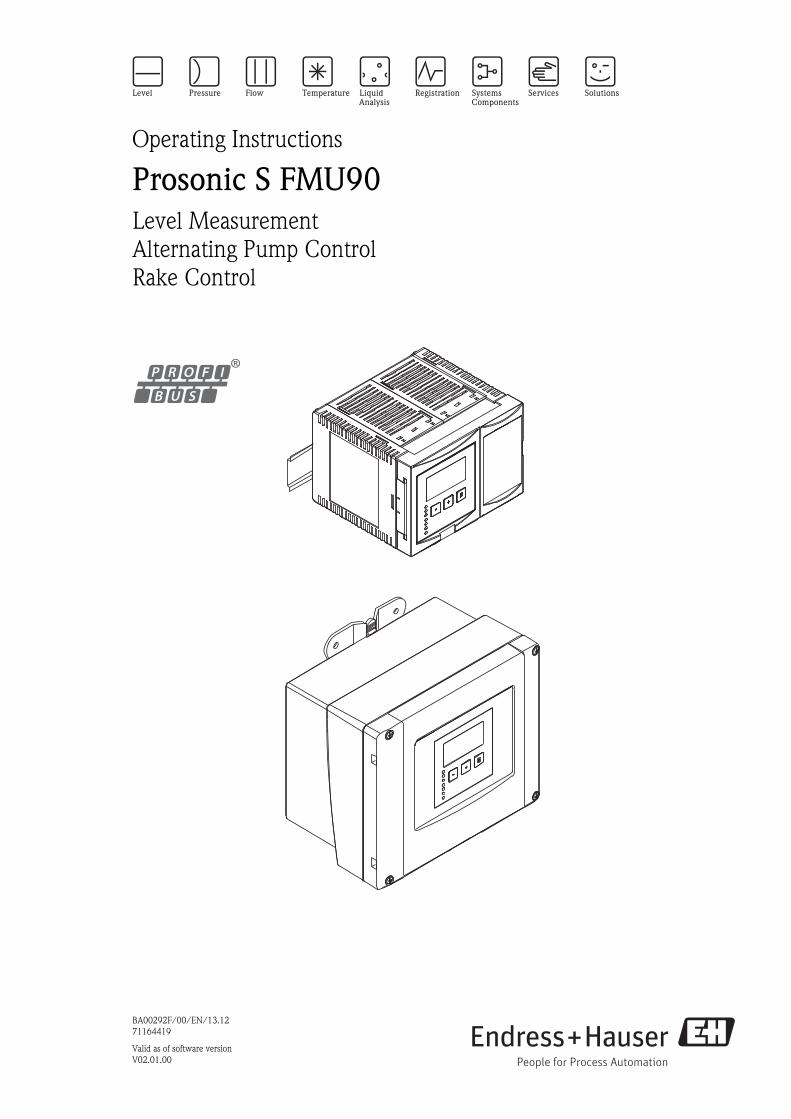
Operating Instructions
Prosonic S FMU90Level Measurement
Alternating Pump Control
Rake Control

Prosonic S FMU90 - level measurement - PROFIBUS DP Table of Contents
Endress+Hauser 3
Table of Contents
1 Safety Instructions . . . . . . . . . . . . . . . . 4
1.1 Designated use . . . . . . . . . . . . . . . . . . . . . . . . . . . . 4
1.2 Installation, commissioning, operation . . . . . . . . . . . 4
1.3 Operational safety and process safety . . . . . . . . . . . . 4
1.4 Notes on safety conventions and symbols . . . . . . . . . 5
2 Identification . . . . . . . . . . . . . . . . . . . . 6
2.1 Parts of the Prosonic S FMU90 . . . . . . . . . . . . . . . . 6
2.2 Nameplate (Example) . . . . . . . . . . . . . . . . . . . . . . . 7
2.3 Product structure . . . . . . . . . . . . . . . . . . . . . . . . . . 8
2.4 Scope of delivery . . . . . . . . . . . . . . . . . . . . . . . . . . . 9
2.5 Certificates and approvals . . . . . . . . . . . . . . . . . . . . 9
2.6 Registered trademarks . . . . . . . . . . . . . . . . . . . . . . . 9
3 Installation . . . . . . . . . . . . . . . . . . . . . 10
3.1 Incoming acceptance, transport, storage . . . . . . . . . 10
3.2 Mounting the field housing . . . . . . . . . . . . . . . . . . 10
3.3 Mounting the DIN-rail housing . . . . . . . . . . . . . . . 12
3.4 Mounting the remote display and operating module 15
3.5 Mounting of the sensors . . . . . . . . . . . . . . . . . . . . 16
3.6 Installation check . . . . . . . . . . . . . . . . . . . . . . . . . 16
4 Wiring . . . . . . . . . . . . . . . . . . . . . . . . 17
4.1 Terminal compartment . . . . . . . . . . . . . . . . . . . . . 17
4.2 Terminal assignment . . . . . . . . . . . . . . . . . . . . . . . 19
4.3 Connection to a PROFIBIS DP network . . . . . . . . . 22
4.4 Sensor connection . . . . . . . . . . . . . . . . . . . . . . . . . 23
4.5 Connection of the sensor heater
(for FDU90/FDU91) . . . . . . . . . . . . . . . . . . . . . . . 25
4.6 Connection of external switches
(for FMU90-********B***) . . . . . . . . . . . . . . . . 27
4.7 Connection of a temperature sensor . . . . . . . . . . . . 27
4.8 Shortening the sensor cable . . . . . . . . . . . . . . . . . . 29
4.9 Synchronization line. . . . . . . . . . . . . . . . . . . . . . . 30
4.10 Connection of the separate display and operating
module . . . . . . . . . . . . . . . . . . . . . . . . . . . . . . . . . 31
4.11 Potential equalization . . . . . . . . . . . . . . . . . . . . . . 32
4.12 Post-connection check . . . . . . . . . . . . . . . . . . . . . . 33
5 Operation . . . . . . . . . . . . . . . . . . . . . . 34
5.1 Operating options . . . . . . . . . . . . . . . . . . . . . . . . . 34
5.2 Operation via the display and operating module . . . 36
5.3 Operation via Endress+Hauser operating tool
"FieldCare" . . . . . . . . . . . . . . . . . . . . . . . . . . . . . . 48
6 Commissioning. . . . . . . . . . . . . . . . . . 49
6.1 Preparatory steps . . . . . . . . . . . . . . . . . . . . . . . . . . 49
6.2 Configuration of the measurement . . . . . . . . . . . . . 54
6.3 Configuration of a limit relay . . . . . . . . . . . . . . . . . 72
6.4 Configuration of an alarm or diagnostic relay . . . . . 77
6.5 Configuration of a pump control - standard . . . . . . 79
6.6 Configuration of a pump control - enhanced . . . . . 93
6.7 Configuration of a rake control . . . . . . . . . . . . . . . 116
6.8 Configuration of a Fieldbus Relay . . . . . . . . . . . . . 121
6.9 Parametrization of the Analog Input (AI) and
Digital Input (DI) blocks . . . . . . . . . . . . . . . . . . . . 122
6.10 Parametrization of the cyclic data telegram . . . . . . 124
6.11 Parametrization of the on-site display . . . . . . . . . . 126
7 Troubleshooting . . . . . . . . . . . . . . . . 129
7.1 System error messages . . . . . . . . . . . . . . . . . . . . . 129
7.2 Possible calibration errors . . . . . . . . . . . . . . . . . . . 136
7.3 Envelope curve display . . . . . . . . . . . . . . . . . . . . . 137
7.4 Software history . . . . . . . . . . . . . . . . . . . . . . . . . . 140
8 Maintenance . . . . . . . . . . . . . . . . . . . 141
8.1 Exterior cleaning . . . . . . . . . . . . . . . . . . . . . . . . . 141
8.2 Repairs . . . . . . . . . . . . . . . . . . . . . . . . . . . . . . . . 141
8.3 Repairs to Ex-approved devices . . . . . . . . . . . . . . 141
8.4 Replacement . . . . . . . . . . . . . . . . . . . . . . . . . . . . 141
8.5 Replacing a sensor . . . . . . . . . . . . . . . . . . . . . . . . 141
8.6 Spare Parts . . . . . . . . . . . . . . . . . . . . . . . . . . . . . 142
8.7 Return . . . . . . . . . . . . . . . . . . . . . . . . . . . . . . . . . 143
8.8 Disposal . . . . . . . . . . . . . . . . . . . . . . . . . . . . . . . . 143
8.9 Contact addresses of Endress+Hauser . . . . . . . . . . 143
9 Accessories . . . . . . . . . . . . . . . . . . . . 144
9.1 Commubox FXA291 . . . . . . . . . . . . . . . . . . . . . . 144
9.2 Protection cover for the field housing . . . . . . . . . . 144
9.3 Mounting plate for the field housing . . . . . . . . . . . 144
9.4 Mounting bracket . . . . . . . . . . . . . . . . . . . . . . . . 145
9.5 Adaption plate for remote display . . . . . . . . . . . . . 146
9.6 Overvoltage protection (in IP66 housing) . . . . . . . 146
9.7 Overvoltage protection HAW562 . . . . . . . . . . . . . 147
9.8 Extension cable for sensors . . . . . . . . . . . . . . . . . 148
9.9 Temperature sensor FMT131 . . . . . . . . . . . . . . . . 149
10 Technical Data. . . . . . . . . . . . . . . . . . 150
10.1 Technical data at a glance . . . . . . . . . . . . . . . . . . 150
11 Operating menu. . . . . . . . . . . . . . . . . 156
11.1 "Level" . . . . . . . . . . . . . . . . . . . . . . . . . . . . . . . . . 156
11.2 "Safety settings" . . . . . . . . . . . . . . . . . . . . . . . . . . 158
11.3 "Relay/Controls" . . . . . . . . . . . . . . . . . . . . . . . . . 160
11.4 "Output/calculations" . . . . . . . . . . . . . . . . . . . . . 168
11.5 "Device properties" . . . . . . . . . . . . . . . . . . . . . . . 169
11.6 "System information" . . . . . . . . . . . . . . . . . . . . . . 170
11.7 "Display" . . . . . . . . . . . . . . . . . . . . . . . . . . . . . . . 172
11.8 "Sensor management" . . . . . . . . . . . . . . . . . . . . . 172
12 Appendix. . . . . . . . . . . . . . . . . . . . . . 173
12.1 Default block configuration . . . . . . . . . . . . . . . . . 173
Index . . . . . . . . . . . . . . . . . . . . . . . . . . . . . 177
Safety Instructions Prosonic S FMU90 - level measurement - PROFIBUS DP
4 Endress+Hauser
1 Safety Instructions
1.1 Designated use
The Prosonic S FMU90 is a transmitter for the ultrasonic sensors FDU90, FDU91, FDU91F, FDU92,
FDU93, FDU95 and FDU96. The sensors of the class FDU8x can be connected as well.
The transmitter version for level measurements ( ä 8, "Product structure":
FMU90 - *1**********) can be applied for different measuring tasks, e.g.:
• level measurement in tanks and silos
• conveyor belt measurement
• level limit detection
• (alternating) pump control, screen and rake control
The version for level and flow measurements ( ä 8, "Product structure":
FMU90 - *2**********) is usable for further measuring tasks, e.g.:
• flow measurement at open flumes and weirs
• (non-resettable) totalizers and (resettable) counters
• control of samplers by time or counting pulses
• backwater and dirt detection in flumes
• simultaneous measurement of level and flow in a stormwater overflow basin with only one sensor
1.2 Installation, commissioning, operation
The Prosonic S FMU90 is fail-safe and constructed to the state-of-the-art. It meets the appropriate
standards and EC directives. However, if you use it improperly or other than for its designated use,
it may pose application-specific hazards, e.g. product overflow due to incorrect installation or
configuration. Installation, electrical connection, start-up, operation and maintenance of the
measuring device must therefore be carried out exclusively by trained specialists authorised by the
system operator. Technical personnel must have read and understood these operating instructions
and must adhere to them. You may only undertake modifications or repair work to the device when
it is expressly permitted by the operating instructions.
1.3 Operational safety and process safety
Alternative monitoring measures must be taken to ensure operational safety and process safety
during configuration, testing and maintenance work on the device.
Hazardous areas
Measuring systems for use in hazardous environments are accompanied by separate "Ex
documentation", which is an integral part of this Operating Manual. Strict compliance with the
installation instructions and ratings as stated in this Additional documentation is mandatory.
• Ensure that all personnel are suitably qualified.
• Observe the specifications in the certificate as well as national and local regulations.
The transmitter may only be installed in suitable areas.
Sensors with a certificate for hazardous areas may be connected to a transmitter without a
certificate.
# Warning!
The sensors FDU83, FDU84, FDU85 and FDU86 with an ATEX, FM or CSA certificate are not
certified for connection to the FMU90 transmitter.
For installations in the USA:
Installation should be in accordance with the National Electrical Code NFPA 70 (NEC)
For installations in Canada:
Installation should be in accordance with the Canadian Electrical Code (CEC)
Prosonic S FMU90 - level measurement - PROFIBUS DP Safety Instructions
Endress+Hauser 5
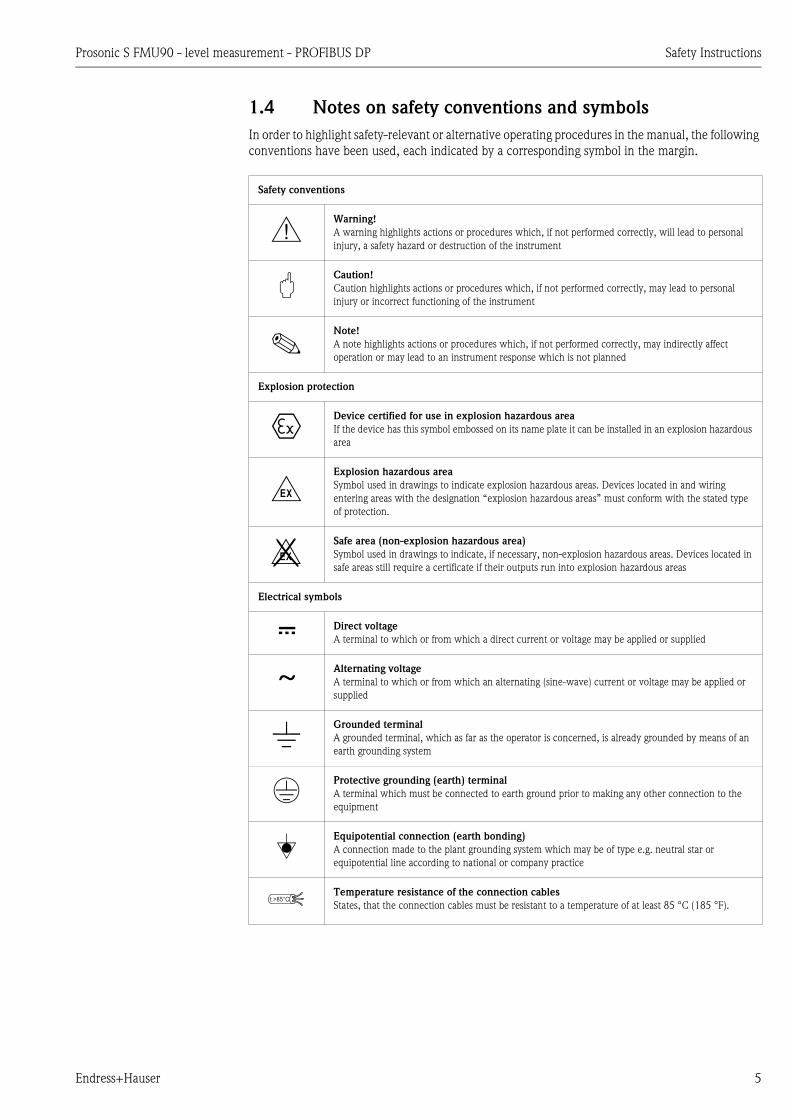
1.4 Notes on safety conventions and symbols
In order to highlight safety-relevant or alternative operating procedures in the manual, the following
conventions have been used, each indicated by a corresponding symbol in the margin.
Safety conventions
#Warning!
A warning highlights actions or procedures which, if not performed correctly, will lead to personal
injury, a safety hazard or destruction of the instrument
"Caution!
Caution highlights actions or procedures which, if not performed correctly, may lead to personal
injury or incorrect functioning of the instrument
!Note!
A note highlights actions or procedures which, if not performed correctly, may indirectly affect
operation or may lead to an instrument response which is not planned
Explosion protection
0Device certified for use in explosion hazardous area
If the device has this symbol embossed on its name plate it can be installed in an explosion hazardous
area
-Explosion hazardous area
Symbol used in drawings to indicate explosion hazardous areas. Devices located in and wiring
entering areas with the designation “explosion hazardous areas” must conform with the stated type
of protection.
.Safe area (non-explosion hazardous area)
Symbol used in drawings to indicate, if necessary, non-explosion hazardous areas. Devices located in
safe areas still require a certificate if their outputs run into explosion hazardous areas
Electrical symbols
% Direct voltage
A terminal to which or from which a direct current or voltage may be applied or supplied
&Alternating voltage
A terminal to which or from which an alternating (sine-wave) current or voltage may be applied or
supplied
)Grounded terminal
A grounded terminal, which as far as the operator is concerned, is already grounded by means of an
earth grounding system
*Protective grounding (earth) terminal
A terminal which must be connected to earth ground prior to making any other connection to the
equipment
+Equipotential connection (earth bonding)
A connection made to the plant grounding system which may be of type e.g. neutral star or
equipotential line according to national or company practice
Temperature resistance of the connection cables
States, that the connection cables must be resistant to a temperature of at least 85 °C (185 °F).t >85°C
Identification Prosonic S FMU90 - level measurement - PROFIBUS DP
6 Endress+Hauser
2 Identification
2.1 Parts of the Prosonic S FMU90
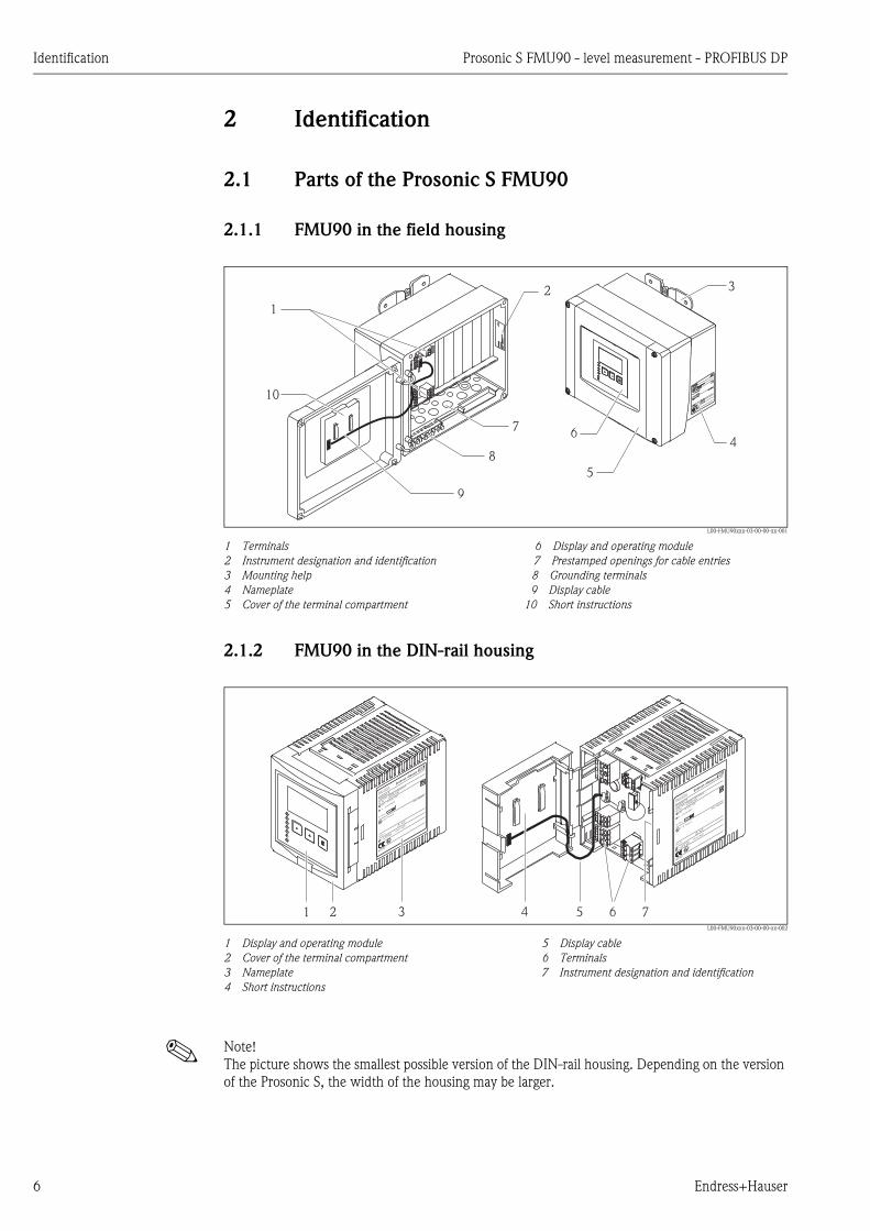
2.1.1 FMU90 in the field housing
L00-FMU90xxx-03-00-00-xx-001
1 Terminals 6 Display and operating module
2 Instrument designation and identification 7 Prestamped openings for cable entries
3 Mounting help 8 Grounding terminals
4 Nameplate 9 Display cable
5 Cover of the terminal compartment 10 Short instructions
2.1.2 FMU90 in the DIN-rail housing
L00-FMU90xxx-03-00-00-xx-002
1 Display and operating module 5 Display cable
2 Cover of the terminal compartment 6 Terminals
3 Nameplate 7 Instrument designation and identification
4 Short instructions
! Note!
The picture shows the smallest possible version of the DIN-rail housing. Depending on the version
of the Prosonic S, the width of the housing may be larger.
Madein
Germany
D-79689
Maulburg
Madein
Germany
D-79689
Maulburg
Prosonic
S
Prosonic
S
Ta > 60°C:
Ta > 60°C:
II 3 DT=xxx°C
II 3 DT=xxx°C
IP66 / NEMA4X
IP66 / NEMA4X
XAxxxF-A
XAxxxF-A
Dat./Insp.:
Dat./Insp.:
if modificatio
n
see sep. label
if modificatio
n
see sep. label
X=
X=
10,5…
32 VDC
10W
10,5…
32 VDC
10W
4 …20 mA
HART
4 …20 mA
HARTOrder Code:
Ser.-No.:
5A01090109A
FMU90-J11AB111AA1A
Order Code:
Ser.-No.:
5A01090109A
FMU90-J11AB111AA1A
Made
inG
erm
any
D-7
9689
Maulb
urg
Made
inG
erm
any
D-7
9689
Maulb
urg
Pro
sonic
SP
rosonic
SO
rder
Code:
Ser.
-No.:
5A
01090109A
FM
U90-J
11A
B111A
A1A
Ord
er
Code:
Ser.
-No.:
5A
010901
09A
FM
U90-J
11A
B111A
A1A
4
3
9
2
5
10
8
1
76
Madein
Germany
D-79689
Maulburg
Prosonic
S
Ta > 60°C:
II 3 DT=xxx°C
IP66 / NEMA4X
XAxxxF-A
Dat./Insp.:
if modificatio
n
see sep. label
X=
10,5…
32 VDC
10W
4 …20 mA
HARTOrder Code:
Ser.-No.:
5A01090109A
FMU90-J11AB111AA1AMade
inGerm
any
D-79689
Maulburg
Prosonic
S
Ta > 60°C:
II 3 DT=xxx°C
IP66 / NEMA4X
XAxxxF-A
Dat./Insp.:
if modificatio
n
see sep. label
X=
10,5…
32 VDC
10W
4 …20 mA
HARTOrder Code:
Ser.-No.:
5A01090109A
FMU90-J11AB11
1AA1A
1 2 3 74 5 6

Prosonic S FMU90 - level measurement - PROFIBUS DP Identification
Endress+Hauser 7
2.1.3 FMU90 with remote display and operating module for cabinet
door and switchboard mounting (96 x 96 mm (3.78 x 3.78 in))
L00-FMU90xxx-03-00-00-xx-040
1 DIN-rail housing without display
2 Remote display and operating module for cabinet mounting
3 The cable (3 m (9.8 ft)) is supplied
! Note!
The picture shows the smallest possible version of the DIN-rail housing. Depending on the version
of the Prosonic S, the width of the housing may be larger.
2.2 Nameplate (Example)
L00-FMU90xxx-18-00-00-xx-002
1 Specification of the electrical protection class (protective insulation)
2 Ingress protection
3 Barcode
4 Marked if a modification nameplate is present
5 Reference to additional safety-relevant documentation
6 Certificate-related data
7 Specification of required temperature resistance of the connection cables
8 Output signal
9 Power supply
10 Serial number
11 Order code (as defined by the product structure)
Madein
Germany
D-79689
Maulburg
Prosonic
S
Ta > 60°C:
II 3 DT=xxx°C
IP66 / NEMA4X
XAxxxF-A
Dat./Insp.:
if modificatio
n
see sep. label
X=
10,5…
32 VDC
10W
4 …20 mA
HARTOrder Code:
Ser.-No.:
5A01090109A
FMU90-J11AB11
1AA1A
1 2
3
Made in GermanyD-79689 Maulburg
Prosonic S
10,5 … 32 V DC 14W
Profibus DP
Order Code:Ser.-No.: 5A01090109A
FMU90-J11CB113AA1A
IP66 / NEMA4X
XAxxxF-A
if modificationsee sep. labelX =
Ta > 60°C :
II 3 D Ex tD A22 T=90°C X
Do not open when energized
11
9
8
7
6
5
4
1
2
3
10

Identification Prosonic S FMU90 - level measurement - PROFIBUS DP
8 Endress+Hauser
2.3 Product structure
(*): meaning of the language code:
cs: Czech; de: German; en: English; es: Spanish; fr: French; id: Bahasa (Indonesia, Malaysia); it:
Italian; ja: Japanese; ko: korean; nl: Dutch; pl: Polish; pt: Portuguese; ru: Russian; th: Thai; zh:
Chinese
010 Approval
R Non-hazarous area
J ATEX II 3D
N CSA General Purpose
020 Application
1 Level + pump control, alternating
2 Flow + totalizer + level + sample control + preprogrammed OCM flow curves
3 Level + additional pump control
4 Universal instrument (Level + Flow + Additional pump control)
030 Housing, material
1 Field mounting PC, IP66 NEMA 4x
2 DIN rail mounting PBT, IP20
040 Operation
C Illuminated display + keypad
E Illuminated display + keypad, 96x96, panel mounting, front IP65
K w/o display, via communication
050 Power supply
A 90-253 VAC
B 10.5-32 VDC
060 Level input
1 1x sensor FDU9x/8x
2 2x sensor FDU9x/8x
070 Switch output
1 1x relay, SPDT
3 3x relay, SPDT
6 6x relay, SPDT
080 Output
1 1x 0/4-20mA HART
2 2x 0/4-20mA HART
3 PROFIBUS DP
090 Additional input
A w/o additional input
B 4x limit switch + 1x temperature PT100/FMT131
100 Datalog function
A Basic version
110 Languages
1 de, en, nl, fr, es, it, pt
2 de, en, ru, pl, cs
3 en, zh, ja, ko, th, id
120 Additional option
A Basic version
L 5-point linearity protocol only to order with FDU9x sensor
+ 5-point linearity protocol
995 Marking
1 Tagging (TAG)
2 Bus address
FMU90 - complete product designation
Prosonic S FMU90 - level measurement - PROFIBUS DP Identification
Endress+Hauser 9
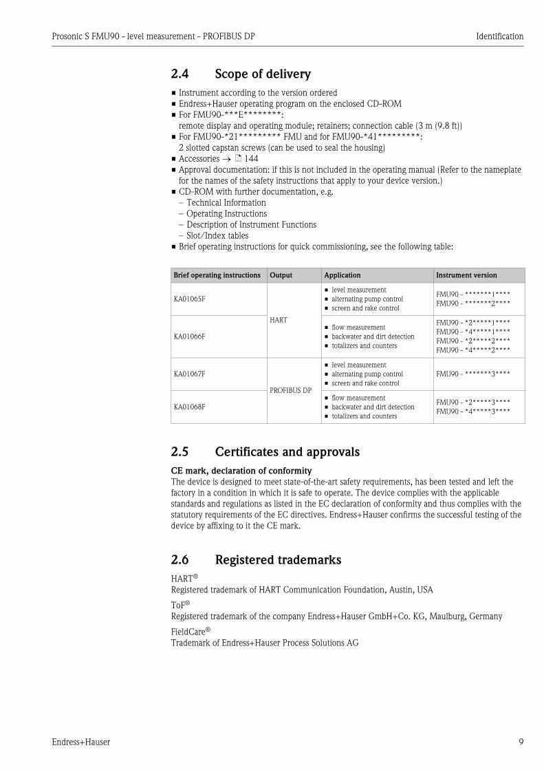
2.4 Scope of delivery
• Instrument according to the version ordered
• Endress+Hauser operating program on the enclosed CD-ROM
• For FMU90-***E********:
remote display and operating module; retainers; connection cable (3 m (9.8 ft))
• For FMU90-*21********* FMU and for FMU90-*41*********:
2 slotted capstan screws (can be used to seal the housing)
• Accessories ä 144
• Approval documentation: if this is not included in the operating manual (Refer to the nameplate
for the names of the safety instructions that apply to your device version.)
• CD-ROM with further documentation, e.g.
– Technical Information
– Operating Instructions
– Description of Instrument Functions
– Slot/Index tables
• Brief operating instructions for quick commissioning, see the following table:
2.5 Certificates and approvals
CE mark, declaration of conformity
The device is designed to meet state-of-the-art safety requirements, has been tested and left the
factory in a condition in which it is safe to operate. The device complies with the applicable
standards and regulations as listed in the EC declaration of conformity and thus complies with the
statutory requirements of the EC directives. Endress+Hauser confirms the successful testing of the
device by affixing to it the CE mark.
2.6 Registered trademarks
HART®
Registered trademark of HART Communication Foundation, Austin, USA
ToF®
Registered trademark of the company Endress+Hauser GmbH+Co. KG, Maulburg, Germany
FieldCare®
Trademark of Endress+Hauser Process Solutions AG
Brief operating instructions Output Application Instrument version
KA01065F
HART
• level measurement
• alternating pump control
• screen and rake control
FMU90 - *******1****
FMU90 - *******2****
KA01066F
• flow measurement
• backwater and dirt detection
• totalizers and counters
FMU90 - *2*****1****
FMU90 - *4*****1****
FMU90 - *2*****2****
FMU90 - *4*****2****
KA01067F
PROFIBUS DP
• level measurement
• alternating pump control
• screen and rake control
FMU90 - *******3****
KA01068F
• flow measurement
• backwater and dirt detection
• totalizers and counters
FMU90 - *2*****3****
FMU90 - *4*****3****
Installation Prosonic S FMU90 - level measurement - PROFIBUS DP
10 Endress+Hauser
3 Installation
3.1 Incoming acceptance, transport, storage
3.1.1 Incoming acceptance
Check the packing and contents for any signs of damage.
Check the shipment, make sure nothing is missing and that the scope of supply matches your order.
3.1.2 Transport, storage
Pack the measuring instrument so that it is protected against impacts for storage and transport. The
original packing material provides the optimum protection for this.
Permissible storage temperature: -40 to +60 °C (-40 to +140 °F)
3.2 Mounting the field housing
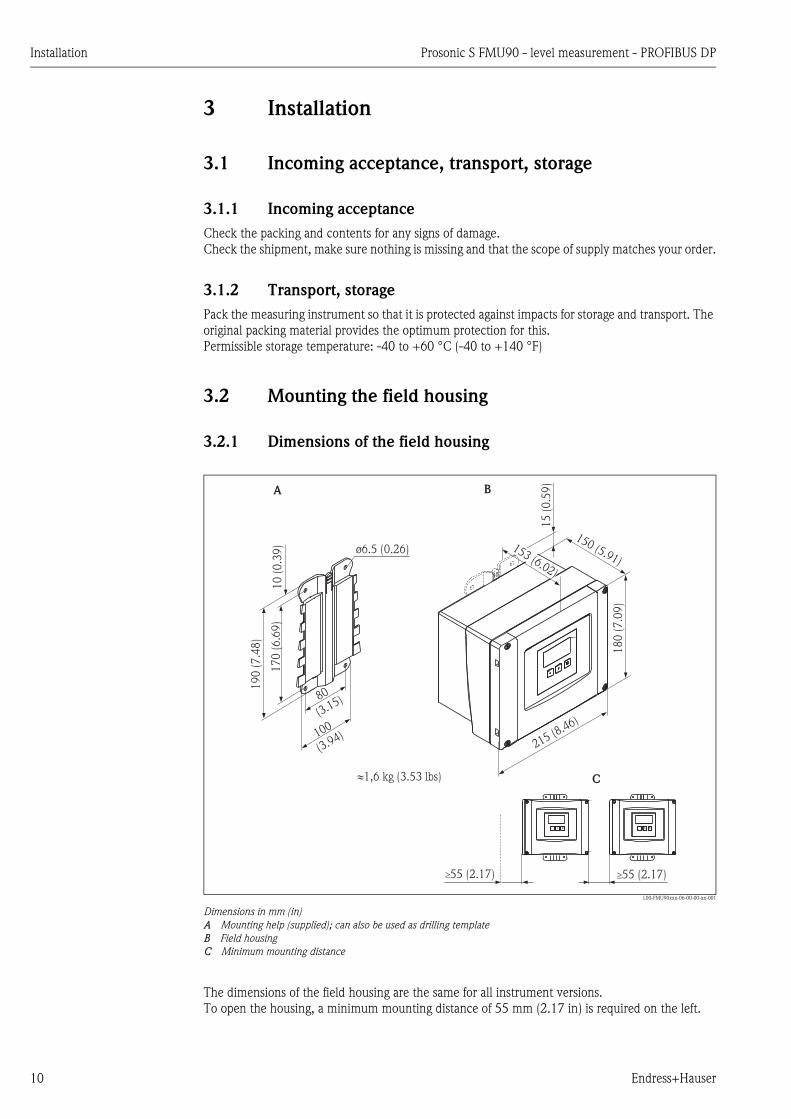
3.2.1 Dimensions of the field housing
L00-FMU90xxx-06-00-00-xx-001
Dimensions in mm (in)
A Mounting help (supplied); can also be used as drilling template
B Field housing
C Minimum mounting distance
The dimensions of the field housing are the same for all instrument versions.
To open the housing, a minimum mounting distance of 55 mm (2.17 in) is required on the left.
215 (8.46)
18
0(7
.09
)
150 (5.91)
15
(0.5
9)
17
0(6
.69
)
19
0(7
.48
)
80
(3.15)
100
(3.94)
ø6.5 (0.26)
10
(0.3
9)
A B
�1,6 kg (3.53 lbs)
153 (6.02)
C
�55 (2.17)�55 (2.17)
Prosonic S FMU90 - level measurement - PROFIBUS DP Installation
Endress+Hauser 11
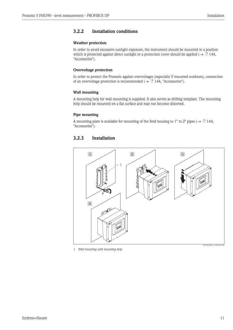
3.2.2 Installation conditions
Weather protection
In order to avoid excessive sunlight exposure, the instrument should be mounted in a position
which is protected against direct sunlight or a protection cover should be applied ( ä 144,
"Accessories").
Overvoltage protection
In order to protect the Prosonic against overvoltages (especially if mounted outdoors), connection
of an overvoltage protection is recommended ( ä 144, "Accessories").
Wall mounting
A mounting help for wall mounting is supplied. It also serves as drilling template. The mounting
help should be mounted on a flat surface and may not become distorted.
Pipe mounting
A mounting plate is available for mounting of the field housing to 1" to 2" pipes ( ä 144,
"Accessories").
3.2.3 Installation
L00-FMU90xxx-17-00-00-xx-003
1 Wall mounting with mounting help
1. 2. 3.
4.
1

Installation Prosonic S FMU90 - level measurement - PROFIBUS DP
12 Endress+Hauser
3.3 Mounting the DIN-rail housing
3.3.1 Dimensions of the DIN-rail housing
The dimensions of the DIN-rail housing depend on the instrument version. The version determines,
which terminal areas the Prosonic S contains. The dimensions are influenced by the following
features of the product structure ( ä 8):
• 60: Level Input
• 70: Switch Output
• 80: Output
In order to determine the dimensions of a specific version, perform the following steps (see the
example ä 13):
1. Using the product structure, determine the options of the features 60, 70 and 80 of the
instrument version in question.
2. Using the following table, determine how many optional terminal areas this instrument version
contains.
3. The appropriate dimensions are given in the following diagram:
10 20 30 40 50 60 70 80 90 100 110 120
FMU90 -
Feature and option of
the product structure
corresponds to the following
terminal area
present?
yes = 1
no = 0
feature 60; option 2
and/or
feature 80, option 2
2 sensor inputs
and/or
2 analogue outputs
feature 70, option 3 or 6 3 o 6 relays
feature 80, option 3 PROFIBUS DP interface
feature 90, option Binputs for external switches and
external temperature sensor
Sum =
Sum = 0
(only basic terminal area)
L00-FMU90xxx-06-00-00-xx-002
Dimensions in mm (in)
Sum = 1, 2 or 3
(1-3 optional terminal areas)
L00-FMU90xxx-06-00-00-xx-005
Dimensions in mm (in)
92 (3.62)
10
4(4
.09
)
140 (5.51)
43
(1.6
9)
EN 60715TH 35x7.5/15(1.4x0.3/0.6)
35
(1.3
8)
0,5 kg (1.10 lbs)�
150 (5.91)
10
4(4
.09
)
140 (5.51)EN 60715TH 35x7.5/15(1.4x0.3/0.6)
35
(1.3
8)
�0,7 kg (1.54 lbs)
42
(1.6
5)
Prosonic S FMU90 - level measurement - PROFIBUS DP Installation
Endress+Hauser 13
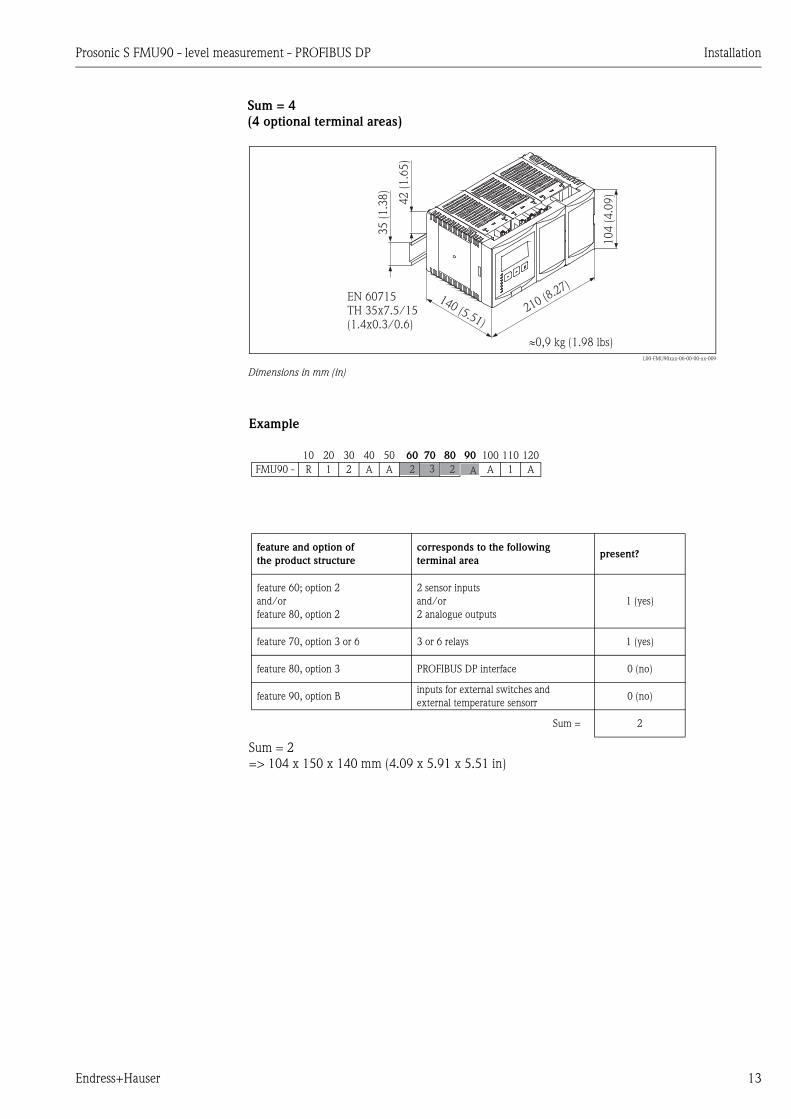
Example
Sum = 2
=> 104 x 150 x 140 mm (4.09 x 5.91 x 5.51 in)
Sum = 4
(4 optional terminal areas)
L00-FMU90xxx-06-00-00-xx-009
Dimensions in mm (in)
210 (8.27)140 (5.51)
EN 60715TH 35x7.5/15(1.4x0.3/0.6)
35
(1.3
8)
�0,9 kg (1.98 lbs)
42
(1.6
5)
10
4(4
.09
)
10 20 30 40 50 60 70 80 90 100 110 120
FMU90 - R 1 2 A A A 1 A
feature and option of
the product structure
corresponds to the following
terminal areapresent?
feature 60; option 2
and/or
feature 80, option 2
2 sensor inputs
and/or
2 analogue outputs
1 (yes)
feature 70, option 3 or 6 3 or 6 relays 1 (yes)
feature 80, option 3 PROFIBUS DP interface 0 (no)
feature 90, option Binputs for external switches and
external temperature sensorr0 (no)
Sum = 2
2 3 2 A
Installation Prosonic S FMU90 - level measurement - PROFIBUS DP
14 Endress+Hauser
3.3.2 Installation conditions
• The DIN-rail housing must be mounted outside hazardous areas in a cabinet.
• The housing is mounted on a DIN rail EN 60715 TH 35x7,5 or TH 37x15.
• Do not install the instrument in the vicinity of high-voltage lines, motor lines, contactors or
frequency converters. The installation regulations for high-voltage lines, motor lines, contactors
or frequency converters must be observed.
• To ensure easy mounting and opening of the housing, a distance of approx. 10 mm (0.39 in)
should be kept between the instruments.
• In order to avoid interference signals, the sensor cables must not be laid parallel to high voltage
or electric power lines.
• The cables may not be laid in the proximity to frequnecy converters.
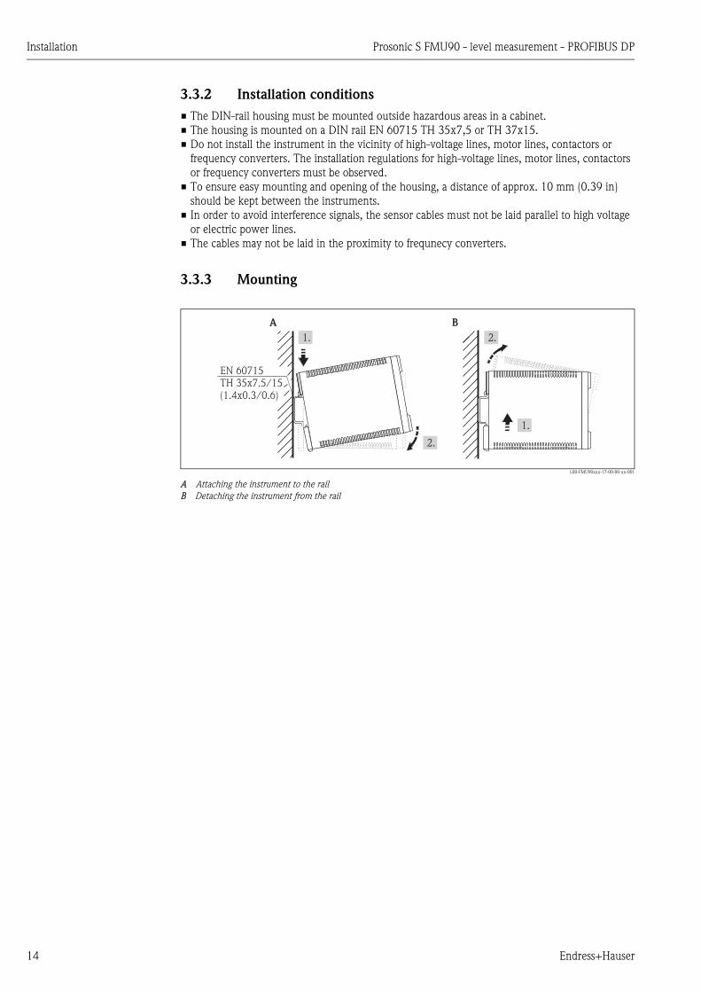
3.3.3 Mounting
L00-FMU90xxx-17-00-00-xx-001
A Attaching the instrument to the rail
B Detaching the instrument from the rail
A B
1.
2.
1.
2.
EN 60715TH 35x7.5/15(1.4x0.3/0.6)

Prosonic S FMU90 - level measurement - PROFIBUS DP Installation
Endress+Hauser 15
3.4 Mounting the remote display and operating module
3.4.1 Scope of delivery
If the Prosonic S is ordered with the display for cabinet door mounting, the following is contained
in the scope of delivery:
• Display and operating module, 96 x 96 mm (3.78 x 3.78 in)
• 4 retainers (with nuts and screws)
• Connection cable (3 m (9.8 ft)) for connection to the transmitter
(preassembled with suitable plugs).
3.4.2 Dimensions of the separate display and operating module
L00-FMU90xxx-06-00-00-xx-004
3.4.3 Mounting
1. Cut an opening of 92 x 92 mm (3.62 x 3.62 in) into the intended mounting position (e.g.
cabinet door).
2. Insert the remote display module into the opening and fix the retainers as shown in the
following figure:
L00-FMU90xxx-17-00-00-xx-002
96
55
max. 6
92 min. 11
~0,5 kg (1.10 lbs)
(0.43)(3.62)
(0.24)(3.78)
(2.17)
mm (in)
1.
3. 4.
2.
Installation Prosonic S FMU90 - level measurement - PROFIBUS DP
16 Endress+Hauser
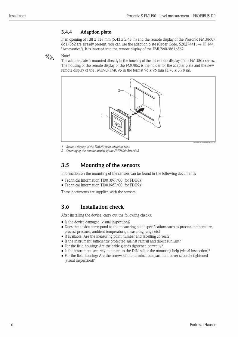
3.4.4 Adaption plate
If an opening of 138 x 138 mm (5.43 x 5.43 in) and the remote display of the Prosonic FMU860/
861/862 are already present, you can use the adaption plate (Order Code: 52027441, ä 144,
"Accessories"). It is inserted into the remote display of the FMU860/861/862.
! Note!
The adapter plate is mounted directly in the housing of the old remote display of the FMU86x series.
The housing of the remote display of the FMU86x is the holder for the adapter plate and the new
remote display of the FMU90/FMU95 in the format 96 x 96 mm (3.78 x 3.78 in).
L00-FMU90xxx-06-00-00-xx-006
1 Remote display of the FMU90 with adaption plate
2 Opening of the remote display of the FMU860/861/862
3.5 Mounting of the sensors
Information on the mounting of the sensors can be found in the following documents:
• Technical Information TI00189F/00 (for FDU8x)
• Technical Information TI00396F/00 (for FDU9x)
These documents are supplied with the sensors.
3.6 Installation check
After installing the device, carry out the following checks:
• Is the device damaged (visual inspection)?
• Does the device correspond to the meausring point specifications such as process temperature,
process pressure, ambient temperature, measuring range etc?
• If available: Are the measuring point number and labelling correct?
• Is the instrument sufficiently protected against rainfall and direct sunlight?
• For the field housing: Are the cable glands tightened correctly?
• Is the instrument securely mounted to the DIN rail or the mounting help (visual inspection)?
• For the field housing: Are the screws of the terminal compartment cover securely tightened
(visual inspection)?
1
2

Prosonic S FMU90 - level measurement - PROFIBUS DP Wiring
Endress+Hauser 17
4 Wiring
# Warning!
The instrument may only be installed if the supply voltage is switched off.
4.1 Terminal compartment
4.1.1 Terminal compartment of the field housing
The field housing has a separate terminal compartment. It can be opened after loosening the four
screws of the lid.
L00-FMU90xxx-04-00-00-xx-002
For easier wiring, the lid can be completely removed by unplugging the display plug and loosening
the hinges:
L00-FMU90KAx-04-00-00-xx-009
4.1.2 Cable entries of the field housing
The following openings for cable entries are prestamped on the bottom of the housing :
• M20x1.5 (10 openings)
• M16x1.5 (5 openings)
• M25x1.5 (1 opening)
The required number and types of cable entries depend on the application at hand.
The prestamped openings can be removed by a suitable tool (e.g. knife or boring bit) or by punching
them out cautiously.
1.
2.
3.
1.
2.

Wiring Prosonic S FMU90 - level measurement - PROFIBUS DP
18 Endress+Hauser
4.1.3 Terminal compartment of the DIN-rail housing
Single instrument
L00-FMU90xxx-04-00-00-xx-003
The catch can be unlocked by slightly pressing onto the clip. Then, the cover of the terminal
compartment can be opened.
Several instruments mounted side by side
L00-FMU90xxx-04-00-00-xx-012
Open the catch of the cover (e.g. by a screwdriver).
Pull the cover out by approx. 20 mm (0.79 in) .
The cover can now be opened.
! Note!
• The cables can be inserted into the housing from above or from below.
• The pictures show the smallest housing version but are valid for the larger versions as well.
• If the instruments are mounted next to each other and if the sensor cables run in parallel, the
synchronization terminals (39 and 40) must be interconnected ( ä 19 "Terminal assignment"
and ä 30 "Synchronization line").
1. 2.
1.
2.
3.
1.
2.
3.
Prosonic S FMU90 - level measurement - PROFIBUS DP Wiring
Endress+Hauser 19
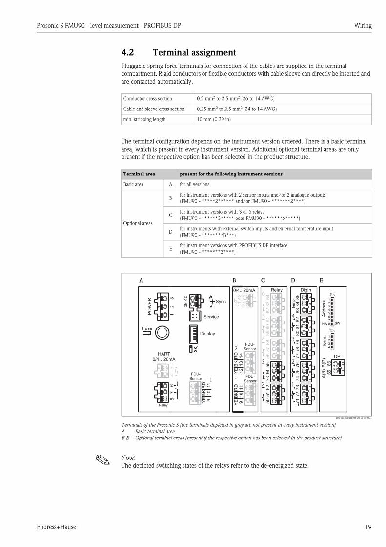
4.2 Terminal assignment
Pluggable spring-force terminals for connection of the cables are supplied in the terminal
compartment. Rigid conductors or flexible conductors with cable sleeve can directly be inserted and
are contacted automatically.
The terminal configuration depends on the instrument version ordered. There is a basic terminal
area, which is present in every instrument version. Additonal optional terminal areas are only
present if the respective option has been selected in the product structure.
L00-FMU90xxx-04-00-00-xx-001
Terminals of the Prosonic S (the terminals depicted in grey are not present in every instrument version)
A Basic terminal area
B-E Optional terminal areas (present if the respective option has been selected in the product structure)
! Note!
The depicted switching states of the relays refer to the de-energized state.
Conductor cross section 0.2 mm2 to 2.5 mm2 (26 to 14 AWG)
Cable and sleeve cross section 0.25 mm2 to 2.5 mm2 (24 to 14 AWG)
min. stripping length 10 mm (0.39 in)
Terminal area present for the following instrument versions
Basic area A for all versions
Optional areas
Bfor instrument versions with 2 sensor inputs and/or 2 analogue outputs
(FMU90 - *****2****** and/or FMU90 - *******2****)
Cfor instrument versions with 3 or 6 relays
(FMU90 - ******3***** oder FMU90 - ******6*****)
Dfor instruments with external switch inputs and external temperature input
(FMU90 - ********B***)
Efor instrument versions with PROFIBUS DP interface
(FMU90 - *******3****)
FDU-Sensor
0/4...20mA
1
42
41
Relay
55
52
54
51
53
50
3
Addre
ss
Term
.
DP
off
on
off
on
SWHW
12345678
1234
A(N
)
66
B(P
)
65
Display
PO
WE
R
HART0/4…20mA
Sync
Fuse
I1FDU-
Sensor
RD
11
BK
10
YE 9
40
39
54
67
8
11
Service
Relay
32
1
A B C E
2
58
57
56
4
61
60
59
5
64
63
62
6
RD
11
BK
10
YE 9
2
RD
14
BK
13
YE
12
I2
FDU-Sensor
DigIn
76
73
75
72
74
71
2
D
1
79
78
77
3
82
81
80
4
85
84
83T
em
p.

Wiring Prosonic S FMU90 - level measurement - PROFIBUS DP
20 Endress+Hauser
Terminals Meaning Terminal area Remarks
Auxiliary energy
1, 2• L (für AC version)
• L+ (for DC version)A depending on instrument version:
• 90 to 253 VAC
• 10,5 to 32 VDC2 • N (for AC version)
• L- (for DC version)
A
3 Potential equalization A
Fuse A depending on instrument version:
• 400 mA T (for AC)
• 2 A T (for DC)
Analog outputs (not available for PROFIBUS DP instruments)
4, 5
Analog output 1;
4 to 20 mA with HART/
0 to 20 mA w/o HART
A not present for the PROFIBUS DP version
41, 42
Analog output 2 (optional);
4 to 20 mA/
0 to 20 mA
Bonly for the version with two analog outputs;
no HART signal at this output
Relay outputs
6, 7, 8 Relay 1 A
50, 51, 52 Relay 2 (optional) C only for the versions with 3 or 6 relays
53, 54, 55 Relay 3 (optional) C only for the versions with 3 or 6 relays
56, 57, 58 Relay 4 (optional) C only for the version with 6 relays
59, 60, 61 Relay 5 (optional) C only for the version with 6 relays
62, 63, 64 Relay 6 (optional) C only for the version with 6 relays
Bus communication (only available for PROFIBUS DP instruments)
65 PROFIBUS A (RxT/TxD - N) Donly for the PROFIBUS DP version
66 PROFIBUS B (RxT/TxD - P) D
Synchronization
39, 40 Synchronization A ä 30 "Synchronization line"
Level inputs
9 (YE),
10 (BK),
11 (RD)
Sensor 1 (FDU8x/9x)
YE: yellow strand
BK: black strand
RD: red strand
• A: for versions with 1 sensor input
• B: for versions with 2 sensor inputs1)
12 (YE),
13 (BK),
14 (RD)
Sensor 2 (FDU8x/9x) (optional)
YE: yellow strand
BK: black strand
RD: red strand
B only for the version with 2 sensor inputs
external switch inputs
71, 72, 73 external switch input 1 D 0: < 8 V or 72 and 73 interconnected
1: > 16 V or 72 and 73 not interconnected
74, 75, 76 external switch input 2 D 0: < 8 V or 75 and 76 interconnected
1: > 16 V or 75 and 76 not interconnected
77, 78, 79 external switch input 3 D 0: < 8 V or 78 and 79 interconnected
1: > 16 V or 78 and 79 not interconnected
80, 81, 82 external switch input 4 D 0: < 8 V or 81 and 82 interconnected
1: > 16 V or 81 and 82 not interconnected
temperature input
83, 84, 85 temperature input:
• PT100
• FMT131 (Endress+Hauser)
D ä 27 "Connection of a temperature sensor"
Prosonic S FMU90 - level measurement - PROFIBUS DP Wiring
Endress+Hauser 21
# Warning!
When using the public supply mains, an easily accesible power switch must be installed in the
proximity of the device. The power switch must be marked as a disconnector for the device (IEC/
EN 61010)
! Note!
• In order to avoid interference signals, the sensor cables should not be laid parallel to high voltage
or electric power lines.
• The cables may not be laid in the proximity to frequnecy converters.
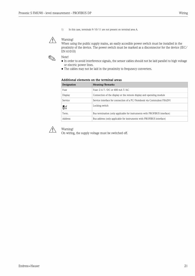
Additional elements on the terminal areas
# Warning!
On wiring, the supply voltage must be switched off.
1) In this case, terminals 9/10/11 are not present on terminal area A.
Designation Meaning/Remarks
Fuse Fuse: 2 A T /DC or 400 mA T/AC
Display Connection of the display or the remote display and operating module
Service Service interface for connection of a PC/Notebook via Commubox FXA291
Locking switch
Term. Bus termination (only applicable for instruments with PROFIBUS interface)
Address Bus address (only applicable for instruments with PROFIBUS interface)
Wiring Prosonic S FMU90 - level measurement - PROFIBUS DP
22 Endress+Hauser
4.3 Connection to a PROFIBIS DP network
! Note!
Information on the structure of a PROFIBUS DP network can be found in the Operating Instructions
BA 034S ("PROFIBUS PA/DP - Guidelines for planning and commissioning".
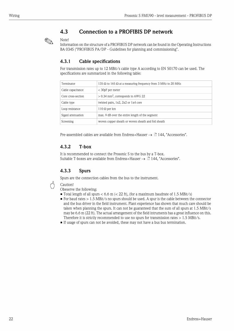
4.3.1 Cable specifications
For transmission rates up to 12 MBit/s cable type A according to EN 50170 can be used. The
specifications are summarized in the following table:
Pre-assembled cables are available from Endress+Hauser ä 144, "Accessories".
4.3.2 T-box
It is recommended to connect the Prosonic S to the bus by a T-box.
Suitable T-boxes are available from Endress+Hauser ä 144, "Accessories".
4.3.3 Spurs
Spurs are the connection cables from the bus to the instrument.
" Caution!
Obeserve the following:
• Total length of all spurs < 6.6 m (< 22 ft), (for a maximum baudrate of 1.5 MBit/s)
• For baud rates > 1.5 MBit/s no spurs should be used. A spur is the cable between the connector
and the bus driver in the field instrument. Plant experience has shown that much care should be
taken when planning the spurs. It can not be guaranteed that the sum of all spurs at 1.5 MBit/s
may be 6.6 m (22 ft). The actual arrangement of the field intruments has a great influence on this.
Therefore it is strictly recommended to use no spurs for transmission rates > 1.5 MBit/s.
• If usage of spurs can not be avoided, these may not have a bus bus termination.
Terminator 135 to 165 at a measuring frequency from 3 MHz to 20 MHz
Cable capacitance < 30pF per meter
Core cross-section > 0.34 mm2, corresponds to AWG 22
Cable type twisted pairs, 1x2, 2x2 or 1x4 core
Loop resistance 110 per km
Siganl attenuation max. 9 dB over the entire length of the segment
Screening woven copper sheath or woven sheath and foil sheath

Prosonic S FMU90 - level measurement - PROFIBUS DP Wiring
Endress+Hauser 23
4.4 Sensor connection
4.4.1 Connection diagram
L00-FDU9xxxx-04-00-00-xx-002
A Without sensor heater
B With sensor heater
C Grounding at the terminal box
D Grounding at the transmitter FMU90
1 Screen of the sensor cable
2 Terminal box
3 Screen of the extension cable
Colours of the strands: YE = yellow; BK = black; RD = red; BU = blue; BN = brown; GNYE = green-yellow
YE9
(12)
BK10
(13)
RD11
(14)
FDU90/91/92(FDU80/80F/81/81F/82)
BKYE RD
1
YE9
(12)
BK10
(13)
RD11
(14)
FDU91F/93/95/96(FDU83/84/85/86)
BKYE RD GNYE
2
3
FMU90
2
3
FMU90
YE9
(12)
BK10
(13)
RD11
(14)
FDU90/91(FDU80/81)
BKYE RD
FMU90
BN BU
24 VDC
+ -
A B
C
YE9
(12)
BK10
(13)
RD11
(14)
FDU91F/93/95/96(FDU83/84/85/86)
BKYE RD GNYE
FMU90
D
FDU90/91/92(FDU80/80F/81/81F/82)
FDU91F/93/95/96(FDU83/84/85/86)
300 m(984 ft)≤
≤30 m(98 ft)
1
300 m(984 ft)≤
≤30 m(98 ft)

Wiring Prosonic S FMU90 - level measurement - PROFIBUS DP
24 Endress+Hauser
4.4.2 Connection hints
" Caution!
• In order to avoid interference signals, the sensor cables should not be laid parallel to high voltage
electric power lines. The cables may not be laid in the proximity to frequency converters.
• The cable screen serves as a return cable and must be connected to the transmitter without any
electrical break. With the pre-assembled cables, the screen ends in a black strand (BK). With the
extension cable, the screen must be twisted together and connected to the "BK" terminal.
# Warning!
• The sensors FDU83, FDU84, FDU85 and FDU86 with an ATEX, FM or CSA certificate are not
certified for connection to the FMU90 transmitter.
• For the sensors FDU91F/93/95/96 and FDU83/84/85/86:
The ground lead (GNYE) must be connected to the local potential equalization after a maximum
distance of 30 m (98 ft). This can be done
– either at the terminal box
– or at the transmitter FMU90 or in the cabinet (if the distance to the sensor does not exceed
30 m (98 ft)).
! Note!
For easier mounting it is advisable to use the sensors FDU90/91/92 and FDU80/80F/81/81F/82
with a maximum cable length of 30 m (98 ft) as well. For longer distances an extension cable with
a terminal box should be used.
4.4.3 Extenxion cables for the sensors
For distances up to 30 m (98 ft) the sensor can be directly connected by the sensor cable. For longer
distances, it is recommended to use an extension cable. The extension cable is connected via a
terminal box. The total length (sensor cable + extension cable) may be up to 300 m (984 ft).
" Caution!
If the terminal box is installed in explosion hazardous areas, all applicable national guidelines must
be observed.
Suitable extension cables can be obtained from Endress+Hauser ( ä 144, "Accessories")
Alternatively, cables with the following properties can be used:
• Number of cores according to the connection diagram (see above)
• braided wire screen for the yellow (YE) and red (RD) core (no foil screen)
• Length: up to 300 m (984 ft) (sensor cable + extension cable)
• Cross section: 0,75 mm2 to 2,5 mm2 (18 to 14 AWG)
• up to 8 per core
• max. 60 nF (between core and screen)
• for FDU91F/93/95/96 and FDU 83/84/85/86:
The earth lead must not be within the screening.
Prosonic S FMU90 - level measurement - PROFIBUS DP Wiring
Endress+Hauser 25
4.5 Connection of the sensor heater (for FDU90/FDU91)
The FDU90 and FDU91 sensors are available in a version with heater. The power for this heater
must be provided by an external power supply unit. The supply voltage is connected to the brown
(BN) and blue (BU) strands of the sensor cable.
Technical Data
• 24 VDC ± 10%; residual ripple < 100 mV
• 250 mA per sensor
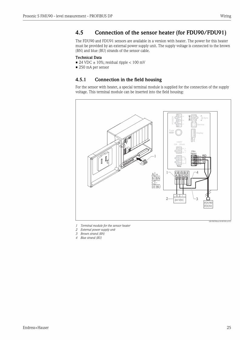
4.5.1 Connection in the field housing
For the sensor with heater, a special terminal module is supplied for the connection of the supply
voltage. This terminal module can be inserted into the field housing:
L00-FMU90xxx-04-00-00-xx-013
1 Terminal module for the sensor heater
2 External power supply unit
3 Brown strand (BN)
4 Blue strand (BU)
Display
PO
WE
R
HART0/4…20mA
Sync
Fuse
I1 FDU-Sensor
RD
11
BK
10
YE 9
40
39
54
67
8
Service
Relay
32
1
4
FDU90FDU91
1
1
324 VDC
+ -
2
RDBK
YE
A B C DA +B BNC -D BU

Wiring Prosonic S FMU90 - level measurement - PROFIBUS DP
26 Endress+Hauser
4.5.2 Connection in the DIN-rail housing
The supply voltage must be provided in the cabinet, e.g. by a terminal on the DIN-rail:
L00-FMU90xxx-04-00-00-xx-014
! Note!
The terminal module supplied with the sensor can also be used for connection of the supply voltage.
For the terminal assignment on this module ä 18.
Display
HART0/4…20mA
Sync
Fuse
I1 FDU-Sensor
RD
11
BK
10
YE 9
40
39
54
67
8
Service
Relay
FMU90
L N
24 VDC
PO
WE
R 32
1
FDU90FDU91
+ -
BN BU
RDBKYE
Prosonic S FMU90 - level measurement - PROFIBUS DP Wiring
Endress+Hauser 27
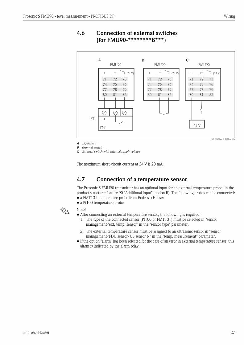
4.6 Connection of external switches
(for FMU90-********B***)
L00-FMU90xxx-04-00-00-xx-021a
A Liquiphant
B External switch
C External switch with external supply voltage
The maximum short-circuit current at 24 V is 20 mA.
4.7 Connection of a temperature sensor
The Prosonic S FMU90 transmitter has an optional input for an external temperature probe (in the
product structure: feature 90 "Additional input", option B). The following probes can be connected:
• a FMT131 temperature probe from Endress+Hauser
• a Pt100 temperature probe
! Note!
• After connecting an external temperature sensor, the following is required:
1. The type of the connected sensor (Pt100 or FMT131) must be selected in "sensor
management/ext. temp. sensor" in the "sensor type" parameter.
2. The external temperature sensor must be assigned to an ultrasonic sensor in "sensor
management/FDU sensor/US sensor N" in the "temp. measurement" parameter.
• If the option "alarm" has been selected for the case of an error in external temperature sensor, this
alarm is indicated by the alarm relay.
PNP
FMU90 FMU90
FTL
A B
FMU90
C
24 V
(24 V)
71 72 73
74 75 76
77 78 79
80 81 82
(24 V)
71 72 73
74 75 76
77 78 79
80 81 82
(24 V)
71 72 73
74 75 76
77 78 79
80 81 82

Wiring Prosonic S FMU90 - level measurement - PROFIBUS DP
28 Endress+Hauser
4.7.1 FMT131 (Endress+Hauser)
(connectable to FMU90-********B***)
L00-FMU90xxx-04-00-00-xx-019
A Non-Ex area (FMT131-R) BK black
B Ex area (FMT131-J) with grounding in the FMU90 YE yellow
C Ex area (FMT131-J) with grounding at a terminal box YEGN yellow-green
! Note!
For details refer to the Operating Instructions KA00019F.
4.7.2 Pt100
(connectable to FMU90-********B***)
L00-FMU90xxx-04-00-00-xx-020
A Pt100 with 3-wire connection
B Pt100 with 4-wire connection (one connector remains unused)
! Note!
A Pt100 with 2-wire connection may not be used due to its insufficient measuring accuracy.
# Warning!
A Pt100 may not be connected in explosion hazardous areas. A FMT131 must be used instead.
83 84
BK YE
FMU9085
YEGN
EX
EX
FMT131-J
EX
EX83 84
BK
BK
YE
YE
YEGN
FMT131-J
FMU90
85
EX
EX
83 84
BK
BK
YE
YE
YEGN
FMT131-R
FMU9085
A CB
83 84 85A
Pt100
83 84
FMU90
85
Pt100
B

Prosonic S FMU90 - level measurement - PROFIBUS DP Wiring
Endress+Hauser 29
4.8 Shortening the sensor cable
If required, the sensor cable can be shortened. Please note:
• Do not damage the cores when removing the insulation.
• The cable is shielded by a metallic braiding. This shielding serves as a return cable and
corresponds to the black (BK) strand of the unshortened cable. After shortening the cable, loosen
the metallic braiding, twist it together securely and connect it to the "BK" terminal.
" Caution!
The protective earth conductor (GNYE), which is present in some of the sensor cables, may not be
electrically connected to the cable shield.
L00-FMU90xxx-04-00-00-xx-015
Colours of the strands: YE = yellow; BK = black; RD = red; BU = blue; BN = brown; GNYE = green-yellow
! Note!
The blue (BU) and brown (BN) strands are only present for sensors with heater.
FDU90/91/92(FDU80/80F/81/81F/82)
FDU91F/93/95/96(FDU83/84/85/86)
RD
BK
YE
RD
BK
YE
24
VD
CBN (+)
BU (-)
GNYE
BN
BU RD
YE
GNYE
RD
YE

Wiring Prosonic S FMU90 - level measurement - PROFIBUS DP
30 Endress+Hauser
4.9 Synchronization line
• If wiring several Prosonic S (FMU90/FMU95)
which are mounted in a common cabinet and
if the sensor cables run in parallel, the
synchronization terminals (39 and 40) must
be interconnected.
• Up to 20 instruments can be synchronized in
this way.
• The synchronization causes the evaluation
units FMU9x to send the pulses
simultaneously. Only after all sensors have
received their signal, new simultaneous pulses
are sent. This prevents pulses in the sensor
cable of one sensor from influencing the
received signal on the cable of a different
sensor.
• If there are more than 20 instruments, groups
must be formed, each containing a maximum
of 20 instruments. For the instruments within
each group, the sensor cables may run in
parallel. The sensor cables of different groups
must be seperated from each other.
• Usual commercial screened cable can be used
for synchronization
– max. length: 10 m (33 ft)between the
individual instruments
– cross section: 2 x (0.75 to 2.5 mm2
(18 to 14 AWG))
– for lengths up to 1 m (3.3 ft), an unscreened
cable can be used; for lenghts exceeding
1 m (3.3 ft), screening is required. The
screen must be connected to ground
• Instruments of the Prosonic FMU86x family
can be connected to the synchronization line
as well. In this case a maximum of 10
instruments can be connected to each
synchronisation line.
L00-FMU90xxx-04-00-00-xx-004
L00-FMU90xxx-04-00-00-xx-017
Prosonic SFMU90/95
39 40
1 2 3 20……
FMU90 FMU90 FMU90
Prosonic SFMU90/95
39 40
Prosonic SFMU90/95
39 40
Prosonic SFMU90/95
39 40
ProsonicFMU860/861/862
63 64
1 2 10……
FMU90
V H
Prosonic S FMU90 - level measurement - PROFIBUS DP Wiring
Endress+Hauser 31
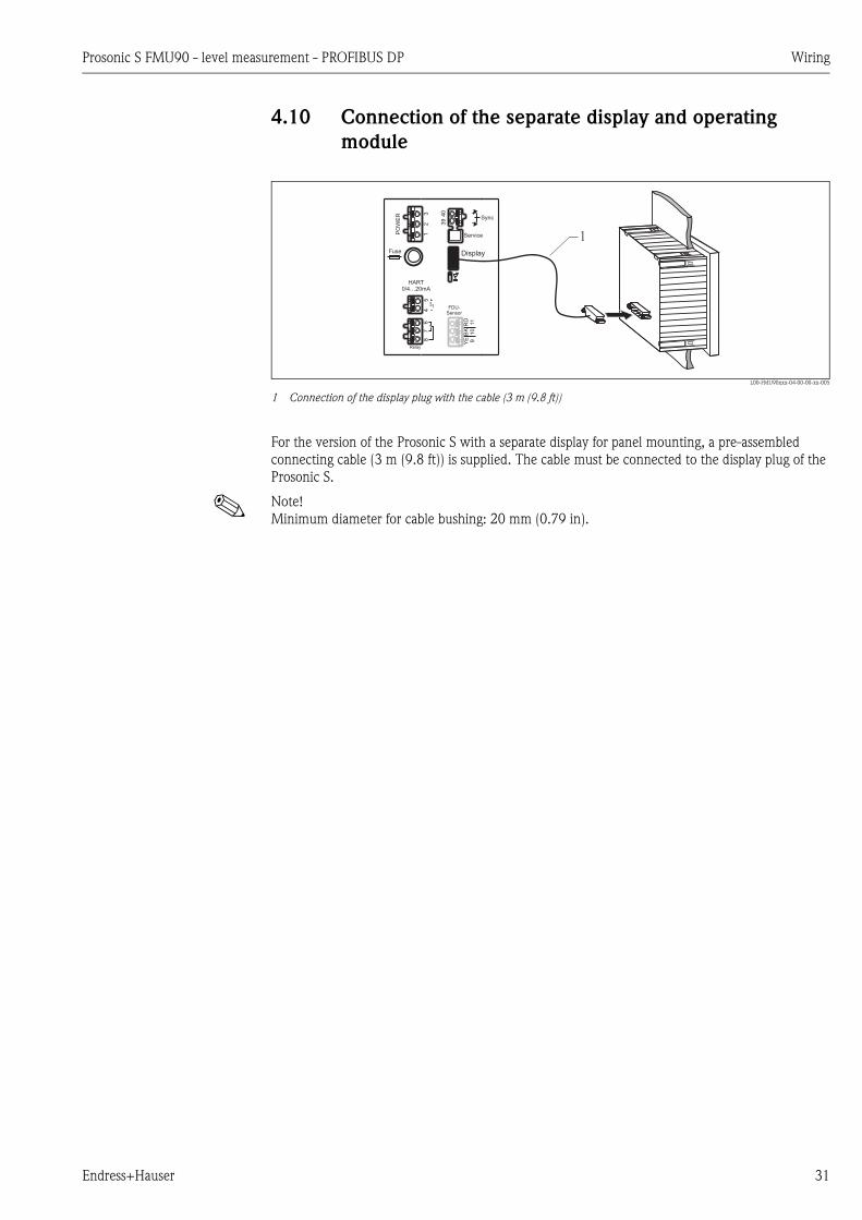
4.10 Connection of the separate display and operating
module
L00-FMU90xxx-04-00-00-xx-005
1 Connection of the display plug with the cable (3 m (9.8 ft))
For the version of the Prosonic S with a separate display for panel mounting, a pre-assembled
connecting cable (3 m (9.8 ft)) is supplied. The cable must be connected to the display plug of the
Prosonic S.
! Note!
Minimum diameter for cable bushing: 20 mm (0.79 in).
Display
PO
WE
R
HART0/4…20mA
Sync
Fuse
I1 FDU-Sensor
RD
11
BK
10
YE 9
40
39
54
67
8
Service
Relay
32
1 1
Wiring Prosonic S FMU90 - level measurement - PROFIBUS DP
32 Endress+Hauser
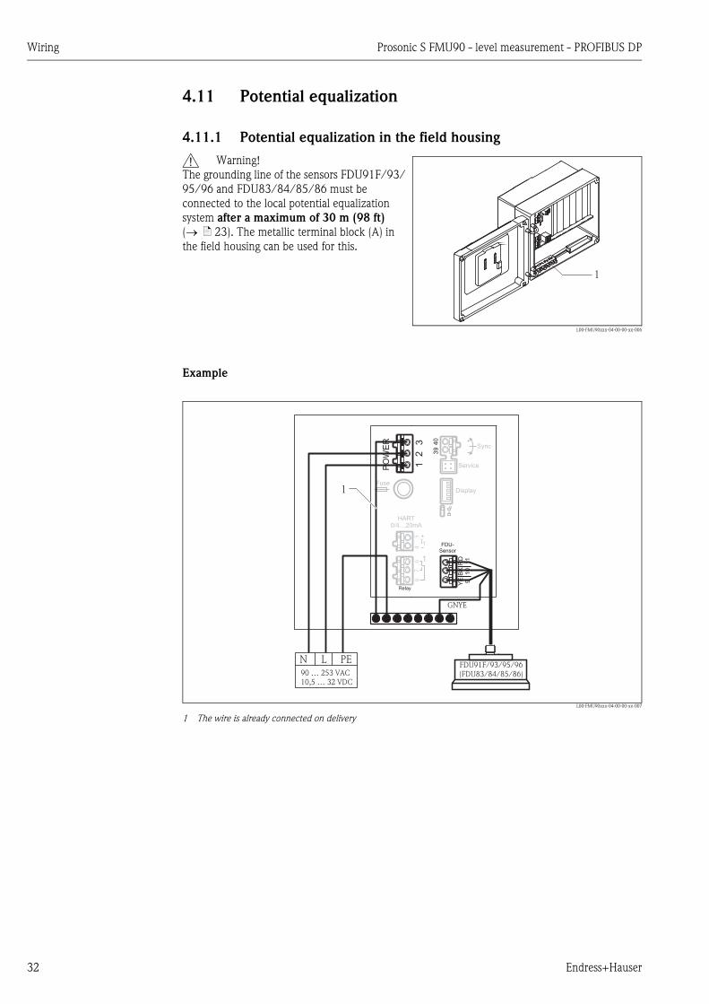
4.11 Potential equalization
4.11.1 Potential equalization in the field housing
Example
L00-FMU90xxx-04-00-00-xx-007
1 The wire is already connected on delivery
# Warning!
The grounding line of the sensors FDU91F/93/
95/96 and FDU83/84/85/86 must be
connected to the local potential equalization
system after a maximum of 30 m (98 ft)
( ä 23). The metallic terminal block (A) in
the field housing can be used for this.
L00-FMU90xxx-04-00-00-xx-006
1
Display
PO
WE
R
HART0/4…20mA
Sync
Fuse
I1 FDU-Sensor
RD
11
BK
10
YE 9
40
39
54
67
8
1
Service
Relay
32
1
90 … 253 VAC10,5 … 32 VDC
N L PE
GNYE
FDU91F/93/95/96(FDU83/84/85/86)
1
Prosonic S FMU90 - level measurement - PROFIBUS DP Wiring
Endress+Hauser 33
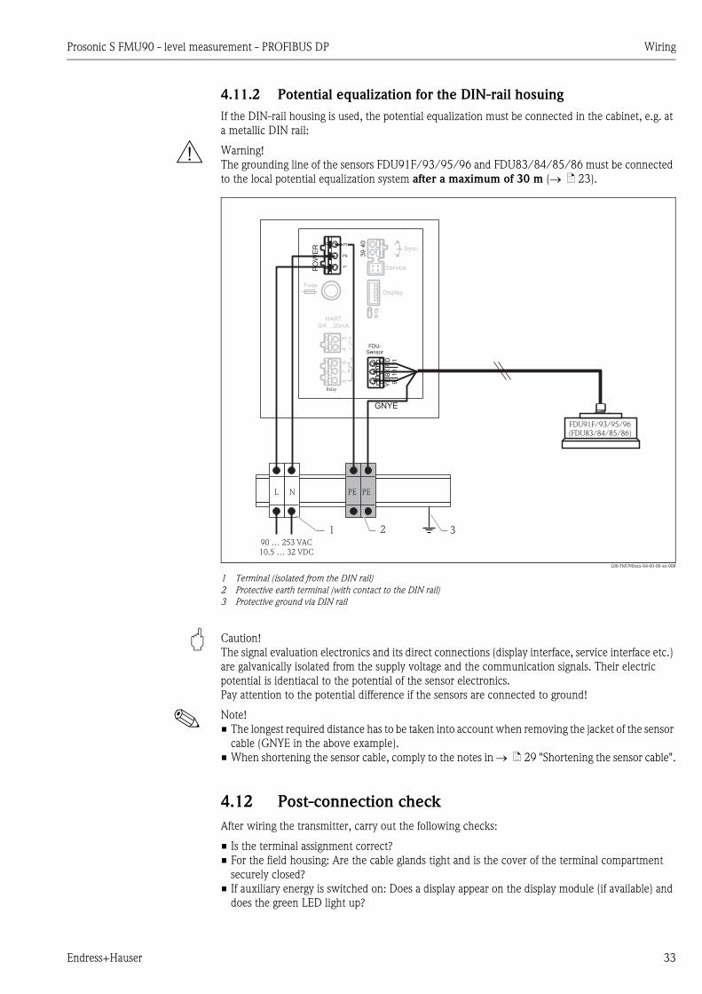
4.11.2 Potential equalization for the DIN-rail hosuing
If the DIN-rail housing is used, the potential equalization must be connected in the cabinet, e.g. at
a metallic DIN rail:
# Warning!
The grounding line of the sensors FDU91F/93/95/96 and FDU83/84/85/86 must be connected
to the local potential equalization system after a maximum of 30 m ( ä 23).
L00-FMU90xxx-04-00-00-xx-008
1 Terminal (isolated from the DIN rail)
2 Protective earth terminal (with contact to the DIN rail)
3 Protective ground via DIN rail
" Caution!
The signal evaluation electronics and its direct connections (display interface, service interface etc.)
are galvanically isolated from the supply voltage and the communication signals. Their electric
potential is identiacal to the potential of the sensor electronics.
Pay attention to the potential difference if the sensors are connected to ground!
! Note!
• The longest required distance has to be taken into account when removing the jacket of the sensor
cable (GNYE in the above example).
• When shortening the sensor cable, comply to the notes in ä 29 "Shortening the sensor cable".
4.12 Post-connection check
After wiring the transmitter, carry out the following checks:
• Is the terminal assignment correct?
• For the field housing: Are the cable glands tight and is the cover of the terminal compartment
securely closed?
• If auxiliary energy is switched on: Does a display appear on the display module (if available) and
does the green LED light up?
Display
PO
WE
RHART
0/4…20mA
Sync
Fuse
I1 FDU-Sensor
RD
11
BK
10
YE 9
40
39
54
67
8
1
Service
Relay
21
GNYE
FDU91F/93/95/96(FDU83/84/85/86)
1
L N PE PE
290 … 253 VAC10.5 … 32 VDC
3
3
Operation Prosonic S FMU90 - level measurement - PROFIBUS DP
34 Endress+Hauser
5 Operation
This chapter gives an overview of the operating options for the intrument. It describes the different
methods of parameter access and states the pre-conditions for each case.
The measning of the individual parameters is not part of this chapter but can be found in:
• Chapter 6: "Commissioning"
• Operating Intructions BA00290F/00: "Prosonic S FMU90 - Description of Instrument Functions"
This chapter contains the following sections:
• 5.1 Operating options
• 5.2 Operation via the display and operating module
• 5.3 Operation via Endress+Hauser operating tool "FieldCare"
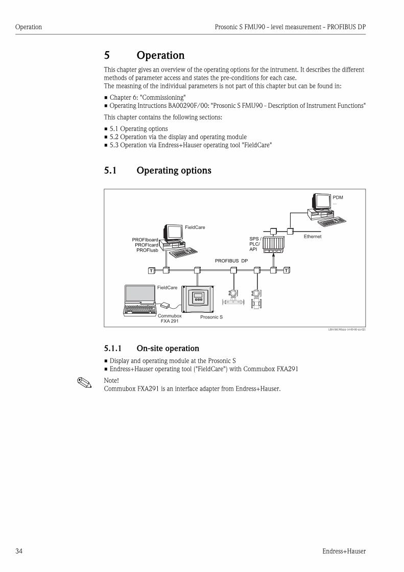
5.1 Operating options
L00-FMU90xxx-14-00-00-xx-021
5.1.1 On-site operation
• Display and operating module at the Prosonic S
• Endress+Hauser operating tool ("FieldCare") with Commubox FXA291
! Note!
Commubox FXA291 is an interface adapter from Endress+Hauser.
PROFIBUS DP
SPS /PLC/API
Ethernet
PDM...
Prosonic S
PROFIboardPROFIcardPROFIusb
CommuboxFXA 291
FieldCare
TT
FieldCare
Prosonic S FMU90 - level measurement - PROFIBUS DP Operation
Endress+Hauser 35
5.1.2 Remote operation
Endress+Hauser operating tool ("FieldCare") with PROFIcard, PROFIboard or PROFIusb
! Note!
PROFIboard, PROFIcard and PROFIusb are interface adapters from Endress+Hauser.
Acyclic data exchange
Remote operation makes use of the acyclic data exchange, which allows device parameters to be
changed independently of the communication between the device and a PLC.
Acyclic data exchange is used
• to transmit device parameters during commissioning and maintenance;
• to display measured values that are not acquired in cyclic traffic.
The Prosonic S supports class 2 masters:
Acyclic communication with a Class 2 master (MS2AC)
In the case of MS2AC, a Class 2 master opens a communication channel via a so-called service
access point (SAP) in order to access the device. Class 2 masters are for example: FieldCare
Before data can be exchanged via PROFIBUS, however, the Class 2 master must be made aware of
the parameters contained within the field device. This can be done by:
• a device description (DD)
• a device type manager (DTM)
• a software component within the master, which accesses the parameters via slot and index
addresses.
! Note!
• The DD or DTM is supplied by the device manufacturer.
• The Prosonic S has one Service Access Point. Therefore, it can be accessed by one Class 2 master.
• The use of a Class 2 master increases the cycle time of the bus system. This must be taken into
consideration when the control system or PLC is programmed.
Slot-Index tables
The Slot-Index tables for the general acyclic data exchange are summarized in the document
BA00333F/00 (can be downloaded from www.endress.com).

Operation Prosonic S FMU90 - level measurement - PROFIBUS DP
36 Endress+Hauser
5.2 Operation via the display and operating module
5.2.1 Display and operating elements
L00-FMU90xxx-07-00-00-xx-002
1 Softkey symbol
2 Key
3 LEDs indicating the switching states of the relays
4 LED indicating the operating state
5 Display symbols
6 Value of the parameter, including unit
7 Name of the parameter
Display symbols
1
2
3
4
5
6
FMU90
4
3
1
2
7
6
5
Symbol Meaning
Operating mode of the instrument
User
User parameters can be edited. Service parameters are locked.
Diagnosis
The service interface is connected.
Service
User and service parameters can be edited.
Locked
All parameters are locked.
Locking state of the currently displayed parameter
Display parameter
The parameter can not be edited in the current operating mode of the instrument.
Editable parameter
The parameter can be edited.
Scroll symbols
Scroll list available
Indicates that the list contains more parameters than can be represented on the display. By pressing
V or W repeatedly, all parameters of the list can be accessed.
Navigation in the envelope curve display
Move left
Move right
Zoom in
Zoom out
Prosonic S FMU90 - level measurement - PROFIBUS DP Operation
Endress+Hauser 37
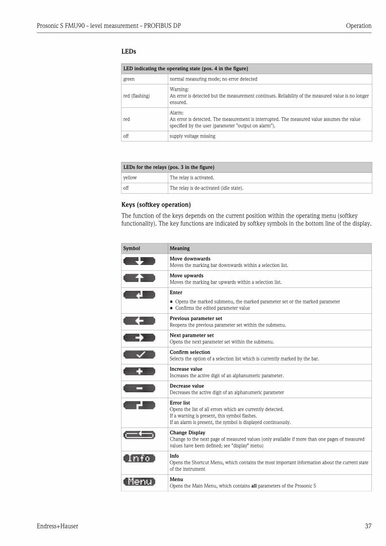
LEDs
Keys (softkey operation)
The function of the keys depends on the current position within the operating menu (softkey
functionality). The key functions are indicated by softkey symbols in the bottom line of the display.
LED indicating the operating state (pos. 4 in the figure)
green normal measuring mode; no error detected
red (flashing)
Warning:
An error is detected but the measurement continues. Reliability of the measured value is no longer
ensured.
red
Alarm:
An error is detected. The measurement is interrupted. The measured value assumes the value
specified by the user (parameter "output on alarm").
off supply voltage missing
LEDs for the relays (pos. 3 in the figure)
yellow The relay is activated.
off The relay is de-activated (idle state).
Symbol Meaning
Move downwards
Moves the marking bar downwards within a selection list.
Move upwards
Moves the marking bar upwards within a selection list.
Enter
• Opens the marked submenu, the marked parameter set or the marked parameter
• Confirms the edited parameter value
Previous parameter set
Reopens the previous parameter set within the submenu.
Next parameter set
Opens the next parameter set within the submenu.
Confirm selection
Selects the option of a selection list which is currently marked by the bar.
Increase value
Increases the active digit of an alphanumeric parameter.
Decrease value
Decreases the active digit of an alphanumeric parameter
Error list
Opens the list of all errors which are currently detected.
If a warning is present, this symbol flashes.
If an alarm is present, the symbol is displayed continuously.
Change Display
Change to the next page of measured values (only available if more than one pages of measured
values have been defined; see "display" menu)
Info
Opens the Shortcut Menu, which contains the most important information about the current state
of the instrument
Menu
Opens the Main Menu, which contains all parameters of the Prosonic S
Operation Prosonic S FMU90 - level measurement - PROFIBUS DP
38 Endress+Hauser
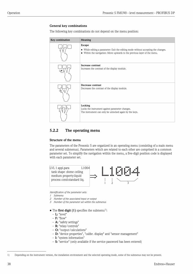
General key combinations
The following key combinations do not depend on the menu position:
5.2.2 The operating menu
Structure of the menu
The parameters of the Prosonic S are organized in an operating menu (consisting of a main menu
and several submenus). Parameters which are related to each other are comprised in a common
parameter set. To simplify the navigation within the menu, a five-digit position code is displayed
with each parameter set.
• The first digit (1) specifies the submenu1):
– L: "level"
– F: "flow"
– A: "safety settings"
– R: "relay/controls"
– O: "output/calculations"
– D: "device properties", "calibr. display" and "sensor management"
– I: "system information"
– S: "service" (only available if the service password has been entered)
Key combination Meaning
Escape
• While editing a parameter: Exit the editing mode without accepting the changes.
• Within the navigation: Move upwards to the previous layer of the menu.
Increase contrast
Increases the contrast of the display module.
Decrease contrast
Decreases the contrast of the display module.
Locking
Locks the instrument against parameter changes.
The instrument can only be unlocked again by the keys.
LVL 1 appl.para L1004
tank shape :dome ceiling
medium property:liquid
process cond:standard liq.
Identification of the parameter sets:
1 Submenu
2 Number of the associated input or output
3 Number of the parameter set within the submenus
1) Depending on the instrument version, the installation environment and the selected operating mode, some of the submenus may not be present.
321
Prosonic S FMU90 - level measurement - PROFIBUS DP Operation
Endress+Hauser 39
Diagrams of the submenus can be found in the chapter "Operating menu".
• The second digit (2) is used if the parameter set occurs several times within the Prosonic S (e.g.
for different inputs or outputs).
Example:
– O1201: "allocation current" for output 1
– O2201: "allocation current" for output 2
If the parameter set occurs only once wihtin the Prosonic S, "X" is indicated at this position.
• The last three digits (3) specify the individual parameter sets within the submenu.
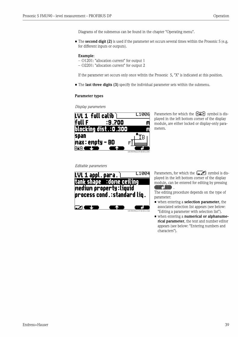
Parameter types
Display parameters
Editable parameters
L00-FMU90xxx-07-00-00-en-041
Parameters for which the symbol is dis-
played in the left bottom corner of the display
module, are either locked or display-only para-
meters.
L00-FMU90xxx-07-00-00-en-044
Parameters, for which the symbol is dis-
played in the left bottom corner of the display
module, can be entered for editing by pressing
.
The editing procedure depends on the type of
parameter:
• when entering a selection parameter, the
associated selection list appears (see below:
"Editing a parameter with selection list").
• when entering a numerical or alphanume-
rical parameter, the text and number editor
appears (see below: "Entering numbers and
characters").
Operation Prosonic S FMU90 - level measurement - PROFIBUS DP
40 Endress+Hauser
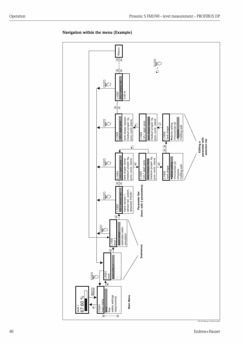
Navigation within the menu (Example)
L00-FMU90xxx-19-00-00-en-050
CX
001
mai
n m
enu
leve
lflo
wsa
fety
set
tings
rala
y/co
ntro
ls…
LX00
1le
vel
L100
2le
vel 1
Ret
urn
inpu
t:se
nsor
1se
nsor
sel
.:au
tom
.de
tect
ed:F
DU
91
tank
sha
pe:d
ome
med
ium
pro
per:
liq.
proc
.con
d.:s
tand
.
5.00
m
leve
l (LV
L) 1
... ...ba
sic
setu
pex
tend
ed c
alib
r.si
mul
atio
n
L100
4LV
L1 a
ppl.
para
tank
sha
pe:d
ome
med
ium
pro
per:
liq.
proc
.con
d.:s
tand
.
L100
Ata
nk s
hape
dom
e ce
iling
horiz
onta
l cyl
.by
pass
still
ing
wel
l
L100
4LV
L1 a
ppl.
para
L100
Ata
nk s
hape
dom
e ce
iling
horiz
onta
l cyl
.by
pass
still
ing
wel
l
L100
4LV
L1 a
ppl.
para
tank
sha
pe:b
ypas
sm
ediu
m p
rope
r:liq
.pr
oc.c
ond.
:sta
nd.
L100
4LV
L1 a
ppl.
para
tank
sha
pe:b
ypas
sm
ediu
m p
rope
r:liq
.pr
oc.c
ond.
:sta
nd.
L100
5LV
L1 e
mpt
y ca
l.
leve
l 1
67.6
0 %
=
L100
3LV
L1 s
enso
r se
l.
Men
u
Mai
n M
enu
Su
bm
enu
sP
aram
eter
Set
(her
e:w
ith
3 p
aram
eter
s)
Ed
itin
g a
par
amet
er w
ith
sele
ctio
n li
st
Prosonic S FMU90 - level measurement - PROFIBUS DP Operation
Endress+Hauser 41
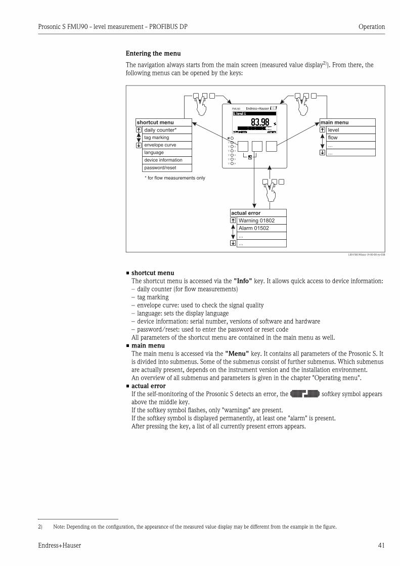
Entering the menu
The navigation always starts from the main screen (measured value display2)). From there, the
following menus can be opened by the keys:
L00-FMU90xxx-19-00-00-yy-038
• shortcut menu
The shortcut menu is accessed via the "Info" key. It allows quick access to device information:
– daily counter (for flow measurements)
– tag marking
– envelope curve: used to check the signal quality
– language: sets the display language
– device information: serial number, versions of software and hardware
– password/reset: used to enter the password or reset code
All parameters of the shortcut menu are contained in the main menu as well.
• main menu
The main menu is accessed via the "Menu" key. It contains all parameters of the Prosonic S. It
is divided into submenus. Some of the submenus consist of further submenus. Which submenus
are actually present, depends on the instrument version and the installation environment.
An overview of all submenus and parameters is given in the chapter "Operating menu".
• actual error
If the self-monitoring of the Prosonic S detects an error, the softkey symbol appears
above the middle key.
If the softkey symbol flashes, only "warnings" are present.
If the softkey symbol is displayed permanently, at least one "alarm" is present.
After pressing the key, a list of all currently present errors appears.
2) Note: Depending on the configuration, the appearance of the measured value display may be differemt from the example in the figure.
shortcut menu main menu
actual error
daily counter* level
Warning 01802
flow
Alarm 01502
tag marking
envelope curve
language
device information
password/reset
* for flow measurements only
...
...
...
...
1
2
3
4
5
6
FMU90
Operation Prosonic S FMU90 - level measurement - PROFIBUS DP
42 Endress+Hauser
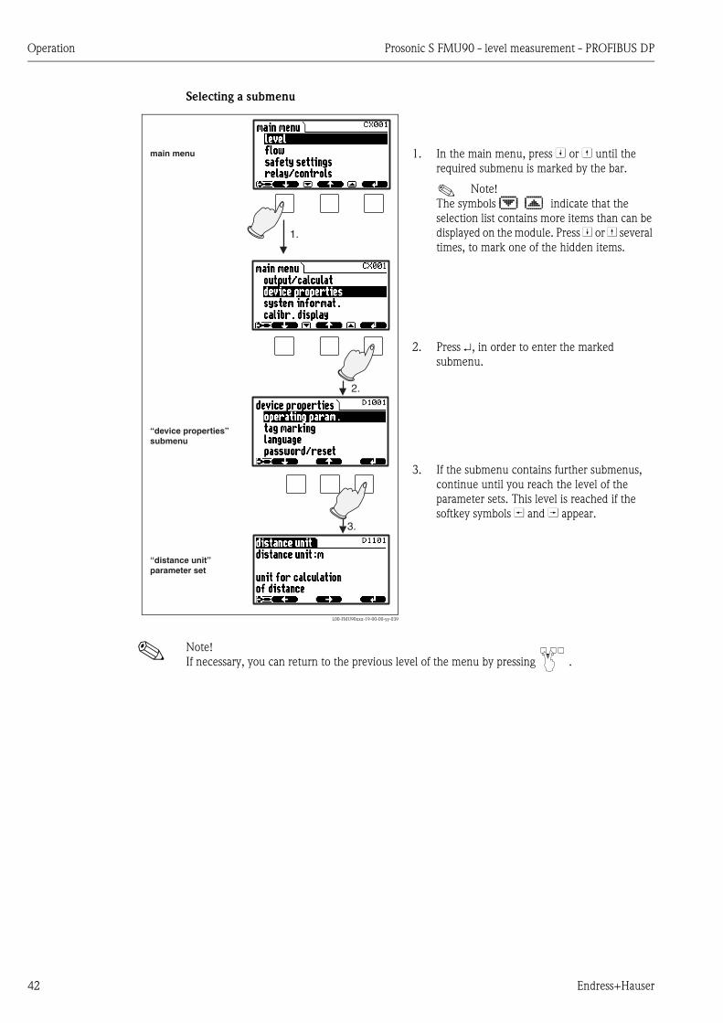
Selecting a submenu
! Note!
If necessary, you can return to the previous level of the menu by pressing .
L00-FMU90xxx-19-00-00-yy-039
1. In the main menu, press W or V until the
required submenu is marked by the bar.
! Note!
The symbols indicate that the
selection list contains more items than can be
displayed on the module. Press W or V several
times, to mark one of the hidden items.
2. Press , in order to enter the marked
submenu.
3. If the submenu contains further submenus,
continue until you reach the level of the
parameter sets. This level is reached if the
softkey symbols U and T appear.
1.
2.
3.
main menu
“device properties”submenu
“distance unit”parameter set

Prosonic S FMU90 - level measurement - PROFIBUS DP Operation
Endress+Hauser 43
Selecting a parameter
By pressing U or T you can switch between the parameter sets of the current submenu. For each
parameter set the values of all its parameters are displayed. In order to change one of the values,
proceed as follows:
! Note!
If necessary, you can exit the parameter and parameter set by pressing .
L00-FMU90xxx-19-00-00-en-040
1. Press U or T, until you have reached the
required parameter set.
2. Press , in order to enter the parameter set.
3. Select the required parameter by pressing
W or V.
(This step is not required if the set contains
only one parameter.)
4. Press , in order to enter the editing mode
of the parameter.
The editing method depends on the type of
parameter (selection list, numeric or
alphanumeric parameter). For details refer
to the following sections.
1. 1.
3.
2.
4.

Operation Prosonic S FMU90 - level measurement - PROFIBUS DP
44 Endress+Hauser
Editing a parameter with selection list
! Note!
By pressing before ✓ you can quit the parameter without accepting your changes.
L00-FMU90xxx-19-00-00-en-041
1. Press W or V, until the required option is
marked by the bar (in the example: "turb.
surface").
! Note!
The symbols indicate that the
selection list contains more items than can
be displayed on the module. Press W or V
several times, to mark one of the hidden
items.
2. Press ✓, in order to select the marked
option. It is then stored in the instrument.
3. Press the left and middle keys
simultaneously in order to quit the
parameter.
The software key symbols U and T
reappear and you can switch to the next
parameter set.
1.
2.
3.

Prosonic S FMU90 - level measurement - PROFIBUS DP Operation
Endress+Hauser 45
Entering numbers and characters
L00-FMU90xxx-19-00-00-yy-042
When you select a numeric parameter ("empty
calibration", "full calibration" etc.) or an alpha-
numeric parameter ("device marking" etc.), the
editor for numbers and text strings appears.
Enter the desired value in the following way:
1. The cursor is at the first digit. Press S or O
until this digit has the required value.
2. Press in order to confirm the value and to
jump to the next digit.
3. Repeat the procedure for all relevant digits.
4. If all relevant digits have been entered:
Press S or O, until appears at the cursor.
5. Press to store the complete value in the
device.
6. Press the left and middle keys simultane-
ously in order to quit the parameter.
1.
2.
3.
4.
5.
6.

Operation Prosonic S FMU90 - level measurement - PROFIBUS DP
46 Endress+Hauser
Special editing functions
Within the editor for alphanumeric characters, pressing S or O does not only lead to numbers and
characters but also to the following symbols for special editing functions. They simplify the editing
procedure.
L00-FMU90xxx-19-00-00-yy-043
Enter: The number left of the cursor is transferred to the instrument.
L00-FMU90xxx-19-00-00-yy-044
Escape: The editor is closed. The parameter maintains its former value. The same behavior can be achieved by pressing
the left and the middle key simultaneously ( ).
L00-FMU90xxx-19-00-00-yy-045
Next digit: The cursor moves on to the next digit.
L00-FMU90xxx-19-00-00-yy-046
Previous digit: The cursor moves back to the previous digit.
Prosonic S FMU90 - level measurement - PROFIBUS DP Operation
Endress+Hauser 47
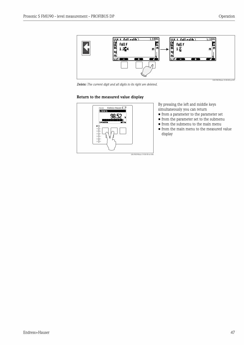
L00-FMU90xxx-19-00-00-yy-047
Delete: The current digit and all digits to its right are deleted.
Return to the measured value display
L00-FMU90xxx-19-00-00-en-048
By pressing the left and middle keys
simultaneously you can return
• from a parameter to the parameter set
• from the parameter set to the submenu
• from the submenu to the main menu
• from the main menu to the measured value
display
1
2
3
4
5
6
FMU90

Operation Prosonic S FMU90 - level measurement - PROFIBUS DP
48 Endress+Hauser
5.3 Operation via Endress+Hauser operating tool
"FieldCare"
L00-FMU90xxx-19-00-00-en-087
Operation via the FieldCare is similar to the operation via the display module.
• The operating menu can be found in the navigation bar (1).
• Input fields for the parameters can be found in the parameter editor (2).
• When you click on a parameter name, the help pages appear. They contain a detailed description
of the respective parameter.
1
2
Prosonic S FMU90 - level measurement - PROFIBUS DP Commissioning
Endress+Hauser 49
6 Commissioning
# Warning!
For the version with field housing: The instrument may only be operated if the field housing is
closed.
This chapter describes the steps of the commissioning procedure:
• 6.1 Preparatory steps
– 6.1.1 Setting the device address
– 6.1.2 Bus termination
– 6.1.3 Loading the devic database files (GSD files)
– 6.1.4 Unlock configuration
– 6.1.5 Reset to the default configuration
• 6.2 Configuration of the measurement
– 6.2.1 First setup
– 6.2.2 Preparing the basic setup
– 6.2.3 Basic setup
– 6.2.4 Checking the measuring signal (envelope curve display)
• 6.3 Configuration of a limit relay
• 6.4 Configuration of an alarm or diagnostic relay
• 6.5 Configuration of a pump control - standard
• 6.6 Configuration of a pump control - enhanced
• 6.7 Configuration of a rake control
• 6.8 Configuration of a Fieldbus relay
• 6.9 Parametrization of the Analog Input (AI) and Digital Input (DI) Blocks
• 6.10 Parametrization fo the cyclic data telegram
• 6.11 Parametrization of the on-site display
6.1 Preparatory steps
6.1.1 Setting the device address
Selecting the device address
• Every PROFIBUS device must be given an address. If the address is not set correctly, the device
will not be recognised by the process control system.
• A device address may appear only once within a particular PROFIBUS network.
• Valid device addresses are in the range between 1 and 126. All devices are delivered from the
factory with the address 126, which is set by software.
• The default address can be used to check the function of the device and connect it to an operating
PROFIBUS system. Afterwards the address must be changed to allow other devices to be
connected to the network.
Software addressing
Software addressing comes into operation, when DIP-switch 8 on the PROFIBUS DP terminal area
is in the position "ON".
In this case, the address can be set by an operating tool ("FieldCare").
The address is displayed in the function "Output-calculations/PROFIBUS DP/instrument address".
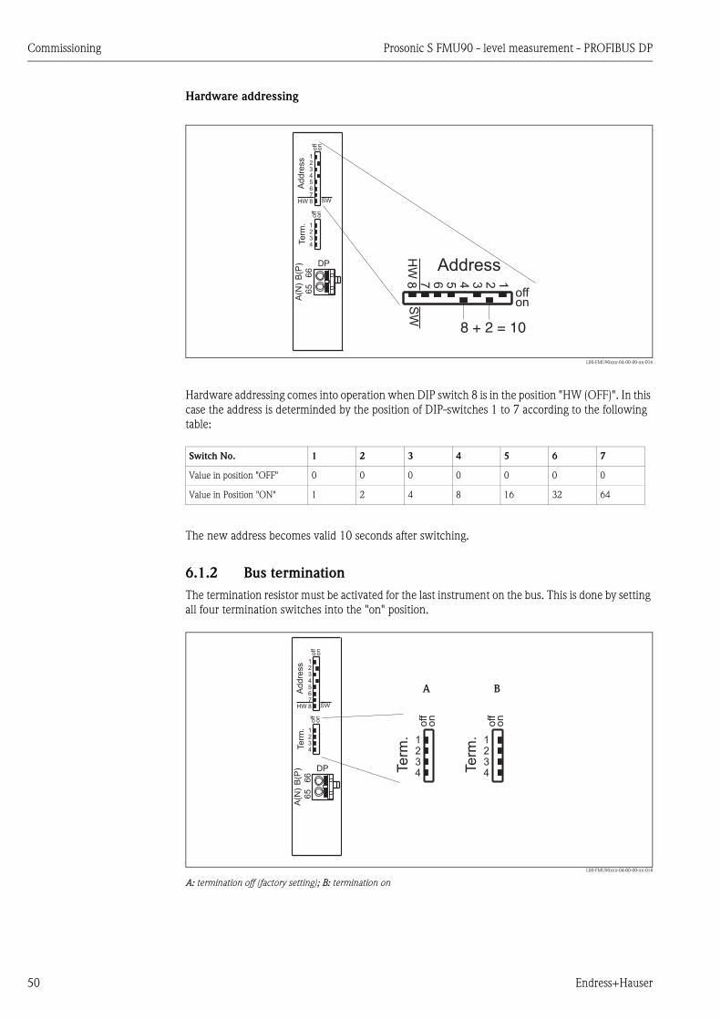
Commissioning Prosonic S FMU90 - level measurement - PROFIBUS DP
50 Endress+Hauser
Hardware addressing
L00-FMU90xxx-04-00-00-xx-016
Hardware addressing comes into operation when DIP switch 8 is in the position "HW (OFF)". In this
case the address is determinded by the position of DIP-switches 1 to 7 according to the following
table:
The new address becomes valid 10 seconds after switching.
6.1.2 Bus termination
The termination resistor must be activated for the last instrument on the bus. This is done by setting
all four termination switches into the "on" position.
L00-FMU90xxx-04-00-00-xx-018
A: termination off (factory setting); B: termination on
Ad
dre
ss
Te
rm.
DP
off
on
off
on
SWHW
12345678
1234
Address
offonS
WH
W
12345678
8 + 2 = 10
A(N
)
66
B(P
)
65
Switch No. 1 2 3 4 5 6 7
Value in position "OFF" 0 0 0 0 0 0 0
Value in Position "ON" 1 2 4 8 16 32 64
Ad
dre
ss
Te
rm.
DP
off
on
off
on
SWHW
12345678
1234
A(N
)
66
B(P
)
65
Term
.
off
on
1234 T
erm
.
off
on
1234
A B

Prosonic S FMU90 - level measurement - PROFIBUS DP Commissioning
Endress+Hauser 51
6.1.3 Loading the device database and type files (GSD)
Meaning of the GSD files
A device database file (GSD) contains a description of the properties of the PROFIBUS device, e.g.
the supported transmission rates and the type and format of the digital information output to the
PLC. Additional bitmap files are required in order to represent the device by an icon in the network
design software. The device database and bitmap files are needed for the commissioning of a
PROFIBUS DP network.
Name of the GSD file
Every device is allocated an identity code by the PROFIBUS User Organisation (PNO). This appears
in the device data base file name (.gsd).
The FMU90 has the ID number 1540(hex) = 5440 (dec).
Therefore, the name of the GSD file is: EH3x1540.gsd
Sources of supply
• www.endress.com
click on "Download" and enter "GSD" into the "Text search" field. The "Software" link opens a list
containing the links to all available GSD files.
• CD-ROM with GSD files for all Endress+Hauser devices. Order-Code: 50097200
• GSD library of the PROFIBUS User Organisation (PNO):http://www.PROFIBUS.com
Directory structure
The files are organized in the following structure:
L00-FMU90xxx-02-00-00-xx-001
Universal Database File
As an alternative to the device specific GSD file, the PNO provides an universal database file without
instrument specific features.
When the universal database file is used, the option "profile" must be selected in the "Output-
calculation/PROFIBUS DP/ident number" parameter.
Usage of the GSD files
The GSD files must be loaded to a specific subdirectory of the PROFIBUS DP configuration software.
Depending on the software, the GSD files must be copied into the directory or an import
functionality of the software may be used.
Detailed information about the appropriate file location can be obtained from the manual of the
respective configuration software.
Prosonic_S/DP/Profile3/Revision1.0/
BMP/
Eh1540_d.bmpEh1540_n.bmpEh1540_s.bmp
DIB/
Eh1540_d.dibEh1540_n.dibEh1540_s.dib
GSD/
Extended/Eh3x1540.gsd
Info/
Liesmich.pdfReadme.pdf
Commissioning Prosonic S FMU90 - level measurement - PROFIBUS DP
52 Endress+Hauser
6.1.4 Unlock configuration
If appears on the display, the instrument is locked against parameter changes. Before
commissioning the instrument must be unlocked.
For the Prosonic S there are three types of locking:
• Software locking
• Locking by key combination
• Hardware locking
Indication of the locking state
The current locking state of the instrument is displayed in the parameter "device properties/
password-reset/status". The following states may occur:
• unlocked
All parameters (except of service parameters) can be changed.
• code locked
The instrument has been locked via the operating menu. It can be unlocked by entering the
unlocking code into the "code" parameter.
• key locked
The key has been locked by a key combination. It can only be unlocked by pressing all three keys
simultaneously.
• switch locked
The instrument has been locked by the switch in the terminal compartment. It can only be
unlocked by this switch.
Software locking
Locking
Go to the parameter "device properties/passoword-reset/code" and enter a value 2457. The
instrument is locked against parameter changes.
The symbol appears on the display.
Unlocking
If you try to change a parameter, the "password-reset" parameter set appears. Select the "code"
parameter and enter "2457". Parameters can be changed again.
Locking by key combination
Locking
Press all three keys simultaneously. The instrument is locked against parameter changes.
The symbol appears on the display.
Unlocking
If you try to change a parameter, the "password/reset" parameter set appears. "key locked" is
displayed in the "status" parameter. Press all three keys simultaneously. Parameters can be changed
again.
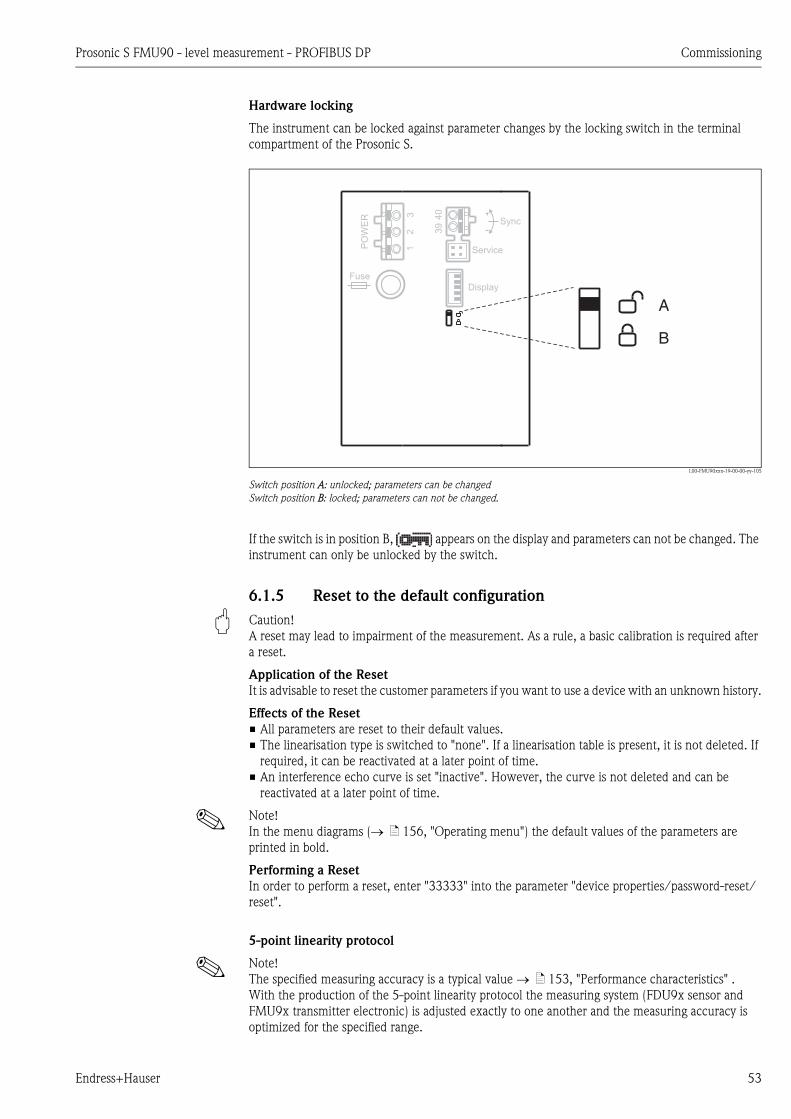
Prosonic S FMU90 - level measurement - PROFIBUS DP Commissioning
Endress+Hauser 53
Hardware locking
The instrument can be locked against parameter changes by the locking switch in the terminal
compartment of the Prosonic S.
L00-FMU90xxx-19-00-00-yy-105
Switch position A: unlocked; parameters can be changed
Switch position B: locked; parameters can not be changed.
If the switch is in position B, appears on the display and parameters can not be changed. The
instrument can only be unlocked by the switch.
6.1.5 Reset to the default configuration
" Caution!
A reset may lead to impairment of the measurement. As a rule, a basic calibration is required after
a reset.
Application of the Reset
It is advisable to reset the customer parameters if you want to use a device with an unknown history.
Effects of the Reset
• All parameters are reset to their default values.
• The linearisation type is switched to "none". If a linearisation table is present, it is not deleted. If
required, it can be reactivated at a later point of time.
• An interference echo curve is set "inactive". However, the curve is not deleted and can be
reactivated at a later point of time.
! Note!
In the menu diagrams ( ä 156, "Operating menu") the default values of the parameters are
printed in bold.
Performing a Reset
In order to perform a reset, enter "33333" into the parameter "device properties/password-reset/
reset".
5-point linearity protocol
! Note!
The specified measuring accuracy is a typical value ä 153, "Performance characteristics" .
With the production of the 5-point linearity protocol the measuring system (FDU9x sensor and
FMU9x transmitter electronic) is adjusted exactly to one another and the measuring accuracy is
optimized for the specified range.
Display
PO
WE
R Sync
Fuse
40
39
Service
32
1
A
B

Commissioning Prosonic S FMU90 - level measurement - PROFIBUS DP
54 Endress+Hauser
To realize this, the parameter "zero distance" is fine adjusted. After a reset the value for the zero
distance has to be re-parameterized in the service menu according to the data on the associated 5-
point linearity protocol for the FDU9x sensor. Please contact the Endress+Hauser service.
6.2 Configuration of the measurement
6.2.1 First setup
! Note!
This chapter describes the commissioning of the Prosonic S via the display and operating module.
Commissioning via FieldCare or the Field Xpert SFX100 is similar. For further instructions refer to
the FieldCare Online Help or the Operating Instructions supplied with the Field Xpert SFX100.
After switching on the power supply for the first time, the instrument asks for a number of operating
parameters:
1. Select the display language.
a. Press or to move the marking bar to the
desired language.
b. Press to confirm your selection.
L00-FMU90xxx-07-00-00-yy-027
2. Select the unit for distance measurements.
L00-FMU90xxx-07-00-00-en-028
3. Select the temperature unit.
L00-FMU90xxx-07-00-00-en-029
4. Select the operating mode.
! Note!
The available options depend on the instrument
version and the installation environment.
L00-FMU90xxx-07-00-00-en-030
5. For level measurements:
Select the control functions, which you are going
to use.
L00-FMU90xxx-07-00-00-en-031
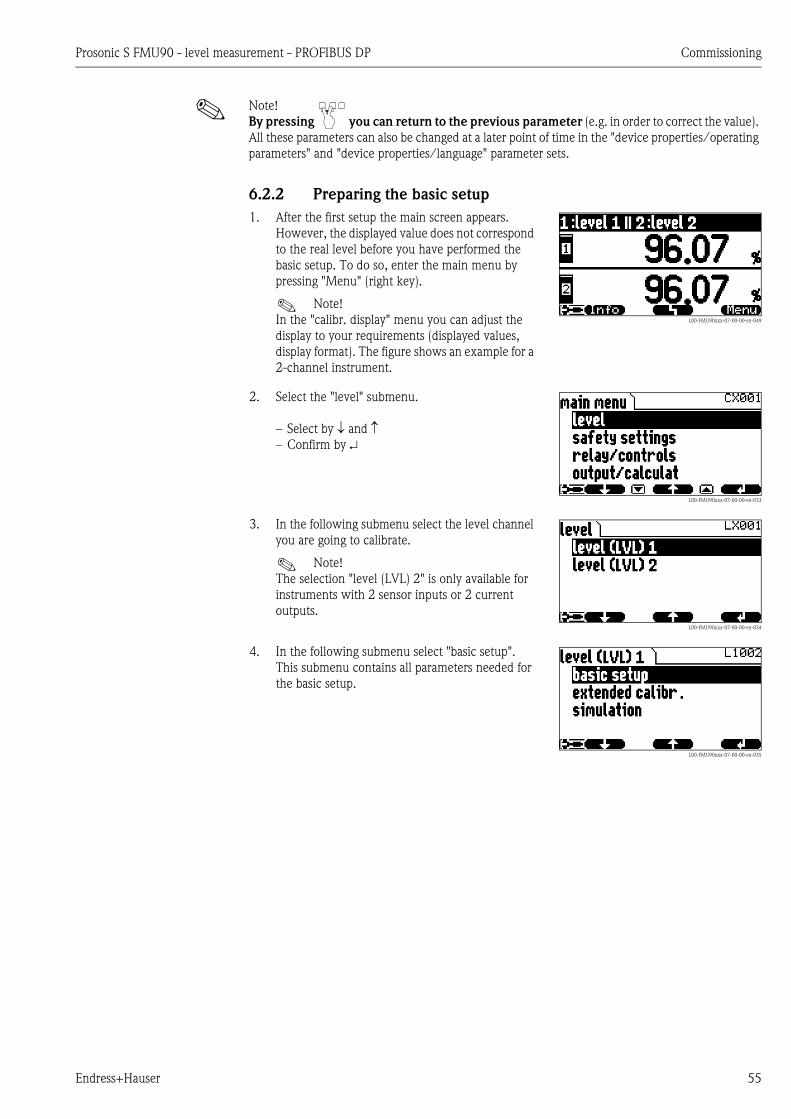
Prosonic S FMU90 - level measurement - PROFIBUS DP Commissioning
Endress+Hauser 55
! Note!
By pressing you can return to the previous parameter (e.g. in order to correct the value).
All these parameters can also be changed at a later point of time in the "device properties/operating
parameters" and "device properties/language" parameter sets.
6.2.2 Preparing the basic setup
1. After the first setup the main screen appears.
However, the displayed value does not correspond
to the real level before you have performed the
basic setup. To do so, enter the main menu by
pressing "Menu" (right key).
! Note!
In the "calibr. display" menu you can adjust the
display to your requirements (displayed values,
display format). The figure shows an example for a
2-channel instrument.
L00-FMU90xxx-07-00-00-en-049
2. Select the "level" submenu.
– Select by and – Confirm by
L00-FMU90xxx-07-00-00-en-033
3. In the following submenu select the level channel
you are going to calibrate.
! Note!
The selection "level (LVL) 2" is only available for
instruments with 2 sensor inputs or 2 current
outputs.L00-FMU90xxx-07-00-00-en-034
4. In the following submenu select "basic setup".
This submenu contains all parameters needed for
the basic setup.
L00-FMU90xxx-07-00-00-en-035
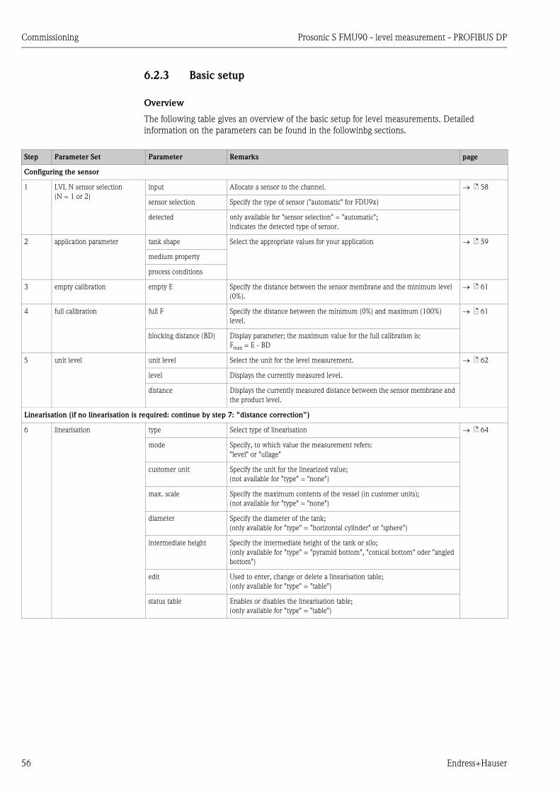
Commissioning Prosonic S FMU90 - level measurement - PROFIBUS DP
56 Endress+Hauser
6.2.3 Basic setup
Overview
The following table gives an overview of the basic setup for level measurements. Detailed
information on the parameters can be found in the followinbg sections.
Step Parameter Set Parameter Remarks page
Configuring the sensor
1 LVL N sensor selection
(N = 1 or 2)
input Allocate a sensor to the channel. ä 58
sensor selection Specify the type of sensor ("automatic" for FDU9x)
detected only available for "sensor selection" = "automatic";
indicates the detected type of sensor.
2 application parameter tank shape Select the appropriate values for your application ä 59
medium property
process conditions
3 empty calibration empty E Specify the distance between the sensor membrane and the minimum level
(0%).
ä 61
4 full calibration full F Specify the distance between the minimum (0%) and maximum (100%)
level.
ä 61
blocking distance (BD) Display parameter; the maximum value for the full calibration is:
Fmax = E - BD
5 unit level unit level Select the unit for the level measurement. ä 62
level Displays the currently measured level.
distance Displays the currently measured distance between the sensor membrane and
the product level.
Linearisation (if no linearisation is required: continue by step 7: "distance correction")
6 linearisation type Select type of linearisation ä 64
mode Specify, to which value the measurement refers:
"level" or "ullage"
customer unit Specify the unit for the linearized value;
(not available for "type" = "none")
max. scale Specify the maximum contents of the vessel (in customer units);
(not available for "type" = "none")
diameter Specify the diameter of the tank;
(only available for "type" = "horizontal cylinder" or "sphere")
intermediate height Specify the intermediate height of the tank or silo;
(only available for "type" = "pyramid bottom", "conical bottom" oder "angled
bottom")
edit Used to enter, change or delete a linearisation table;
(only available for "type" = "table")
status table Enables or disables the linearisation table;
(only available for "type" = "table")
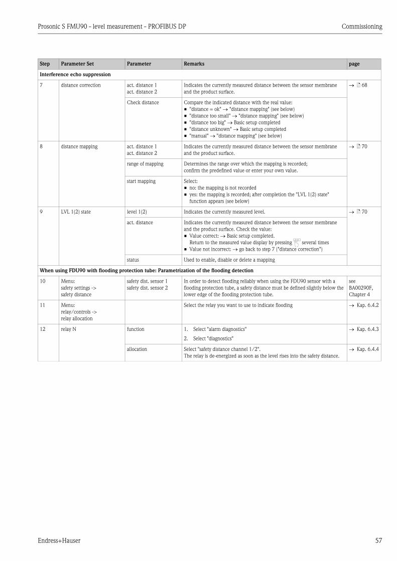
Prosonic S FMU90 - level measurement - PROFIBUS DP Commissioning
Endress+Hauser 57
Step Parameter Set Parameter Remarks page
Interference echo suppression
7 distance correction act. distance 1
act. distance 2
Indicates the currently measured distance between the sensor membrane
and the product surface.
ä 68
Check distance Compare the indicated distance with the real value:
• "distance = ok" "distance mapping" (see below)
• "distance too small" "distance mapping" (see below)
• "distance too big" Basic setup completed
• "distance unknown" Basic setup completed
• "manual" "distance mapping" (see below)
8 distance mapping act. distance 1
act. distance 2
Indicates the currently measured distance between the sensor membrane
and the product surface.
ä 70
range of mapping Determines the range over which the mapping is recorded;
confirm the predefined value or enter your own value.
start mapping Select:
• no: the mapping is not recorded
• yes: the mapping is recorded; after completion the "LVL 1(2) state"
function appears (see below)
9 LVL 1(2) state level 1(2) Indicates the currently measured level. ä 70
act. distance Indicates the currently measured distance between the sensor membrane
and the product surface. Check the value:
• Value correct: Basic setup completed.
Return to the measured value display by pressing several times
• Value not incorrect: go back to step 7 ("distance correction")
status Used to enable, disable or delete a mapping
When using FDU90 with flooding protection tube: Parametrization of the flooding detection
10 Menu:
safety settings ->
safety distance
safety dist. sensor 1
safety dist. sensor 2
In order to detect flooding reliably when using the FDU90 sensor with a
flooding protection tube, a safety distance must be defined slightly below the
lower edge of the flooding protection tube.
see
BA00290F,
Chapter 4
11 Menu:
relay/controls ->
relay allocation
Select the relay you want to use to indicate flooding Kap. 6.4.2
12 relay N function 1. Select "alarm diagnostics"
2. Select "diagnostics"
Kap. 6.4.3
allocation Select "safety distance channel 1/2".
The relay is de-energized as soon as the level rises into the safety distance.
Kap. 6.4.4

Commissioning Prosonic S FMU90 - level measurement - PROFIBUS DP
58 Endress+Hauser
"LVL N sensor selection" (N = 1 or 2)
"input"
Use this parameter to assign a sensor to the channel.
Selection:
• no sensor
• sensor 1
• sensor 2 (only for 2-channel instruments)
"sensor selection"
Use this parameter to specify the type of the connected ultrasonic sensor.
! Note!
• For the sensors FDU9x the option "automatic" is recommended (default setting). With this setting
the Prosonic S recognizes the type of sensor automatically.
• For the sensors FDU8x the type has to be assigned explicitly. The automatic sensor recognition
does not work for these sensors.
" Caution!
After exchanging a sensor, observe the following:
The automatic sensor recognition is also active after a sensor has been exchanged3). The Prosonic S
recognizes the type of the new sensor automatically and changes the "detected" parameter if
required. The measurement continues without a break.
Nevertheless, in order to ensure perfect measurement, the following checks are required:
• Check the "empty calibration" and "full calibration" parameters. Adjust these values if
required. Take into account the blocking distance of the new sensor.
• Go to the "distance correction" parameter set and check the displayed distance. If required,
perform a new interference echo suppression.
"detected" (only available for "sensor selection" = "automatic")
Indicates the type of the automatically detected sensor.
LVL1 sensor sel. L1003
input:
sensor selection:
detected:
3) if the new sensor is of the type FDU9x
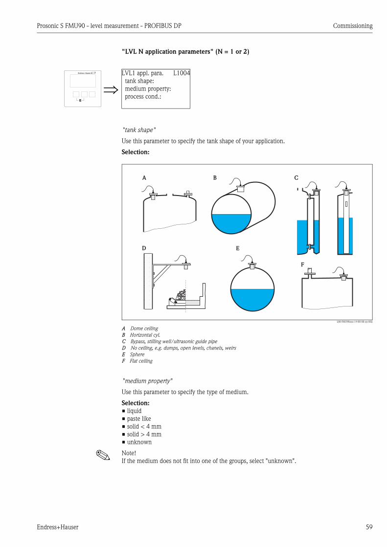
Prosonic S FMU90 - level measurement - PROFIBUS DP Commissioning
Endress+Hauser 59
"LVL N application parameters" (N = 1 or 2)
"tank shape"
Use this parameter to specify the tank shape of your application.
Selection:
L00-FMU90xxx-14-00-00-xx-002
A Dome ceiling
B Horizontal cyl.
C Bypass, stilling well/ultrasonic guide pipe
D No ceiling, e.g. dumps, open levels, chanels, weirs
E Sphere
F Flat ceiling
"medium property"
Use this parameter to specify the type of medium.
Selection:
• liquid
• paste like
• solid < 4 mm
• solid > 4 mm
• unknown
! Note!
If the medium does not fit into one of the groups, select "unknown".
LVL1 appl. para. L1004
tank shape:
medium property:
process cond.:
A B C
D E
F
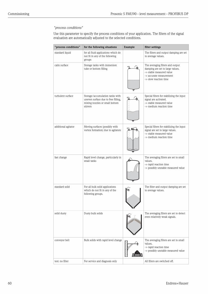
Commissioning Prosonic S FMU90 - level measurement - PROFIBUS DP
60 Endress+Hauser
"process conditions"
Use this parameter to specify the process conditions of your application. The filters of the signal
evaluation are automatically adjusted to the selected conditions.
"process conditions" for the following situations Example filter settings
standard liquid for all fluid applications which do
not fit in any of the following
groups
The filters and output damping are set
to average values.
calm surface Storage tanks with immersion
tube or bottom filling
The averaging filters and output
damping are set to large values.
-> stable measured value
-> accurate measurement
-> slow reaction time
turbulent surface Storage/accumulation tanks with
uneven surface due to free filling,
mixing nozzles or small bottom
stirrers
Special filters for stabilizing the input
signal are activated.
-> stable measured value
-> medium reaction time
additional agitator Moving surfaces (possibly with
vortex formation) due to agitators
Special filters for stabilizing the input
signal are set to large values.
-> stable measured value
-> medium reaction time
fast change Rapid level change, particularly in
small tanks
The averaging filters are set to small
values.
-> rapid reaction time
-> possibly unstable measured value
standard solid For all bulk solid applications
which do not fit in any of the
following groups.
The filter and output damping are set
to average values.
solid dusty Dusty bulk solids The averaging filters are set to detect
even relatively weak signals.
conveyor belt Bulk solids with rapid level change The averaging filters are set to small
values.
-> rapid reaction time
-> possibly unstable measured value
test: no filter For service and diagnosis only All filters are switched off.

Prosonic S FMU90 - level measurement - PROFIBUS DP Commissioning
Endress+Hauser 61
"LVL N empty calibration" (N = 1 or 2)
"empty E"
"LVL N full calibration" (N = 1 or 2)
"full F"
LVL1 empty cal. L1005
empty E: 0,00 m
L00-FMU90xxx-19-00-00-yy-007
Use this parameter to specify the empty distance E, i.e. the
distance between the sensor membrane (reference point of the
measurement) and the minimum level (zero point).
– Default: max. measuring range of the respective sensor
– Range of values: depending on sensor type
" Caution!
The zero point should not be deeper than the point at which the
ultrasonic wave impinges on the tank bottom
0/4mA0%
E
LVL1 full calib. L1006
full F: 0,00 m
block.dist. BD:
L00-FMU90xxx-19-00-00-yy-008
Use this parameter to specify the span F, i.e. the distance from the
minimum level to the maximum level.
– Default setting: depending on sensor type
– Range of values: depending on sensor type
– blocking distance BD: depending on sensor type (see table)
" Caution!
The maximum level may not project into the blocking distance:
Fmax = E - BD
20mA100%
0/4mA0%
BD
FE
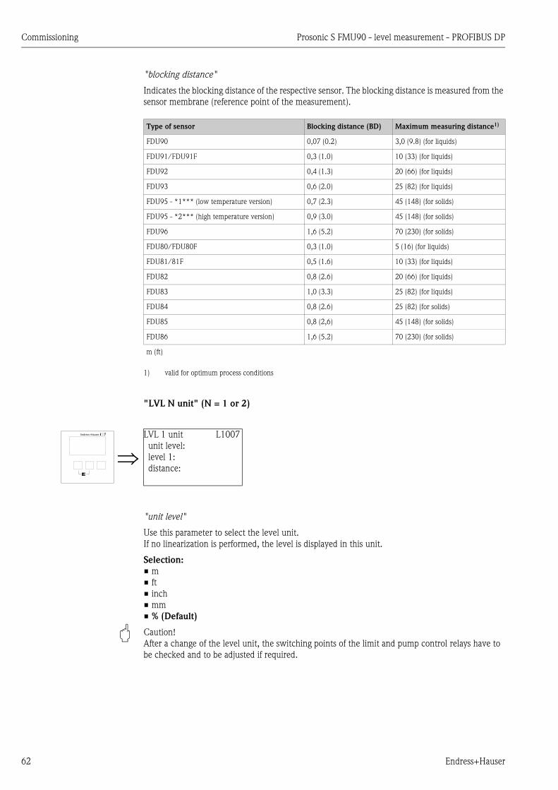
Commissioning Prosonic S FMU90 - level measurement - PROFIBUS DP
62 Endress+Hauser
"blocking distance"
Indicates the blocking distance of the respective sensor. The blocking distance is measured from the
sensor membrane (reference point of the measurement).
"LVL N unit" (N = 1 or 2)
"unit level"
Use this parameter to select the level unit.
If no linearization is performed, the level is displayed in this unit.
Selection:
• m
• ft
• inch
• mm
• % (Default)
" Caution!
After a change of the level unit, the switching points of the limit and pump control relays have to
be checked and to be adjusted if required.
Type of sensor Blocking distance (BD) Maximum measuring distance1)
1) valid for optimum process conditions
FDU90 0,07 (0.2) 3,0 (9.8) (for liquids)
FDU91/FDU91F 0,3 (1.0) 10 (33) (for liquids)
FDU92 0,4 (1.3) 20 (66) (for liquids)
FDU93 0,6 (2.0) 25 (82) (for liquids)
FDU95 - *1*** (low temperature version) 0,7 (2.3) 45 (148) (for solids)
FDU95 - *2*** (high temperature version) 0,9 (3.0) 45 (148) (for solids)
FDU96 1,6 (5.2) 70 (230) (for solids)
FDU80/FDU80F 0,3 (1.0) 5 (16) (for liquids)
FDU81/81F 0,5 (1.6) 10 (33) (for liquids)
FDU82 0,8 (2.6) 20 (66) (for liquids)
FDU83 1,0 (3.3) 25 (82) (for liquids)
FDU84 0,8 (2.6) 25 (82) (for solids)
FDU85 0,8 (2,6) 45 (148) (for solids)
FDU86 1,6 (5.2) 70 (230) (for solids)
m (ft)
LVL 1 unit L1007
unit level:
level 1:
distance:
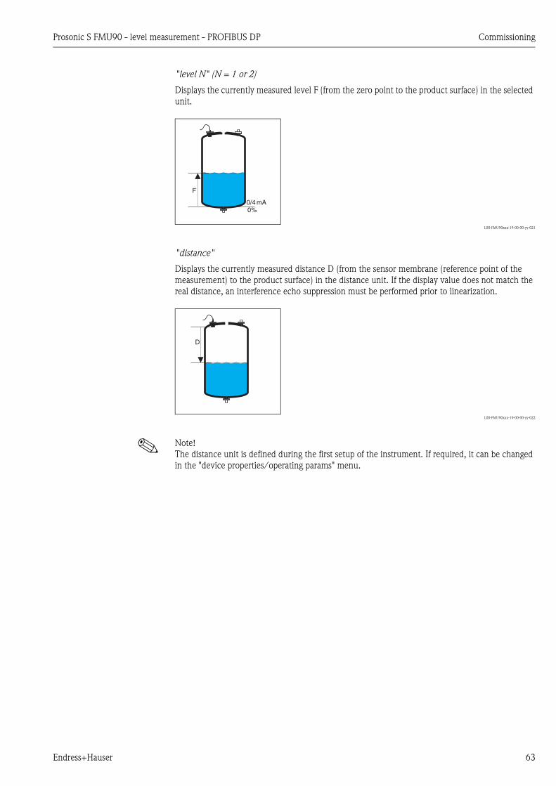
Prosonic S FMU90 - level measurement - PROFIBUS DP Commissioning
Endress+Hauser 63
"level N" (N = 1 or 2)
Displays the currently measured level F (from the zero point to the product surface) in the selected
unit.
L00-FMU90xxx-19-00-00-yy-021
"distance"
Displays the currently measured distance D (from the sensor membrane (reference point of the
measurement) to the product surface) in the distance unit. If the display value does not match the
real distance, an interference echo suppression must be performed prior to linearization.
L00-FMU90xxx-19-00-00-yy-022
! Note!
The distance unit is defined during the first setup of the instrument. If required, it can be changed
in the "device properties/operating params" menu.
0/4mA0%
F
D
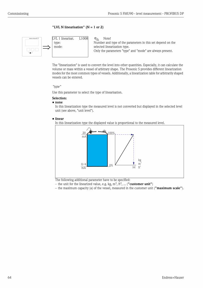
Commissioning Prosonic S FMU90 - level measurement - PROFIBUS DP
64 Endress+Hauser
"LVL N linearisation" (N = 1 or 2)
The "linearization" is used to convert the level into other quantities. Especially, it can calculate the
volume or mass within a vessel of arbitrary shape. The Prosonic S provides different linearization
modes for the most common types of vessels. Additionally, a linearization table for arbitrarily shaped
vessels can be entered.
"type"
Use this parameter to select the type of linearisation.
Selection:
• none
In this linearization type the measured level is not converted but displayed in the selected level
unit (see above, "unit level").
• linear
In this linearization type the displayed value is proportional to the measured level.
The following additional parameter have to be specified:
– the unit for the linearized value, e.g. kg, m3, ft3, ... ("customer unit")
– the maximum capacity (a) of the vessel, measured in the customer unit ("maximum scale").
LVL 1 linearisat. L1008
type:
mode:
! Note!
Number and type of the parameters in this set depend on the
selected linearization type.
Only the parameters "type" and "mode" are always present.
100%20mA
0%0/4mA (a)
kg
m
ft
3
3

Prosonic S FMU90 - level measurement - PROFIBUS DP Commissioning
Endress+Hauser 65
• horizontal cylinder4)
• sphere
In these linearization types the measured level is convertet to the volume in a horizontal cylinder
or a spherical tank.
The following additional parameters have to be specified:
– the unit of the linearized value, e.g. kg, m3, ft3, ... ("customer unit")
– the diameter (D) of the tank ("diameter")
– the maximum capacity (a) of the tank, measured in the customer unit ("maximum scale").
• angled bottom (A)
• pyramid bottom (B)
• conical bottom (B)
In these linearisation modes the measured level is converted to the volume in the respective type
of vessel.
The following additional parameters have to be specified:
– the unit for the linearized value, e.g. kg, m3, ft3, ... ("customer unit")
– the intermediate height H according to the diagram ("intermediate height")
– the maximum capacity (a) of the tank, measured in the customer unit ("maximum scale").
4) This option is only valid for horizontal cylinders without dome ceiling. For tanks with dome ceiling FieldCare can be used to calculate a linearisation table and
to upload it into the instrument.
100%20mA
0%0/4mA
(D)Ø
(a)
kg
m
ft
3
3
100%20mA
0%0/4mA
= kg,m3, ft3, ...
H
(a)
A B
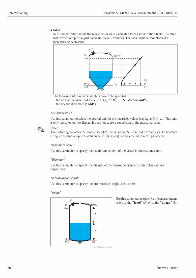
Commissioning Prosonic S FMU90 - level measurement - PROFIBUS DP
66 Endress+Hauser
• table
In this linearization mode the measured value is calculated from a linearization table. The table
may consist of up to 32 pairs of values (level - volume). The table must be monotonically
increasing or decreasing.
The following additional parameters have to be specified:
– the unit of the linearized value, e.g. kg, m3, ft3, ... ("customer unit")
– the linearization table ("edit")
"customer unit"
Use this parameter to select the desired unit for the linearized values (e.g. kg, m3, ft3, ...). This unit
is only indicated on the display. It does not cause a conversion of the measured value.
! Note!
After selecting the option "customer specific", the parameter "customized text" appears. An arbitrary
string (consisting of up to 5 alphanumeric characters) can be entered into this parameter.
"maximum scale"
Use this parameter to specify the maximum content of the vessel in the customer unit.
"diameter"
Use this parameter to specify the diamter of the horizontal cylinder or the spherical tank
respectively.
"intermediate height"
Use this parameter to specify the intermediate height of the vessel.
"mode"
100%20mA
0%0/4mA
kg
m
ft
3
3
L00-FMU90xxx-19-00-00-yy-015
Use this parameter to specify if the measurement
refers to the "level" (A) or to the "ullage" (B).100%20
mA
0%0/4mA
A
B
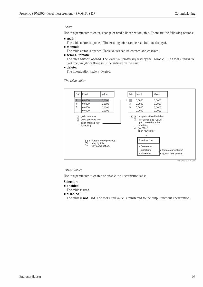
Prosonic S FMU90 - level measurement - PROFIBUS DP Commissioning
Endress+Hauser 67
"edit"
Use this parameter to enter, change or read a linearization table. There are the following options:
• read:
The table editor is opened. The existing table can be read but not changed.
• manual:
The table editor is opened. Table values can be entered and changed.
• semi-automatic:
The table editor is opened. The level is automatically read by the Prosonic S. The measured value
(volume, weight or flow) must be entered by the user.
• delete:
The linearization table is deleted.
The table editor
L00-FMU90xxx-19-00-00-de-006
"status table"
Use this parameter to enable or disable the linearization table.
Selection:
• enabled
The table is used.
• disabled
The table is not used. The measured value is transferred to the output without linearization.
No. Level Value
1 0,0000 0,0000
2 0,0000 0,0000
3 0,0000 0,0000
… 0,0000 0,0000
: go to next row
: go to previous row
: open marked rowfor editing
No. Level Value
1 0,0000 0,0000
2 0,0000 0,0000
3 0,0000 0,0000
… 0,0000 0,0000
: navigate within the table
: (for "Level" und "Value”)open marked numberfor editing
: (for "No.")open row editor
Row function
(before current row)
Query: new position
Return to the previousstep by thiskey combination. - Delete row
- Insert row
- Move row

Commissioning Prosonic S FMU90 - level measurement - PROFIBUS DP
68 Endress+Hauser
Interference echo suppression: Basic principles
The "check value" and "distance mapping" parameters are used to configure the interference
echo suppression of the Prosonic S.
The following picture shows the operating principle of the interference echo suppression:
L00-FMU90xxx-19-00-00-yy-017
A: The envelope curve (a) contains the level echo and an interference echo. Without interference echo suppression, the
interference echo is evaluated.
B: The interference echo suppression generates the mapping curve (b). This curve suppresses all echos within the range
of mapping (c).
C: From now on, only those echos are evaluated, which are higher than the mapping curve. The interference echo is below
the mapping curve and is therefore ignored.
! Note!
In order to include all interference echos, the interference echo suppression should be performed
with the level as low as possible. If during commissioning the vessel can not be sufficiently emptied,
it is advisable to repeat the interference echo suppression at a later point of time (as soon as the level
reaches nearly 0%).
A B
(a) (a) (b)
(c)
C
(a) (b)
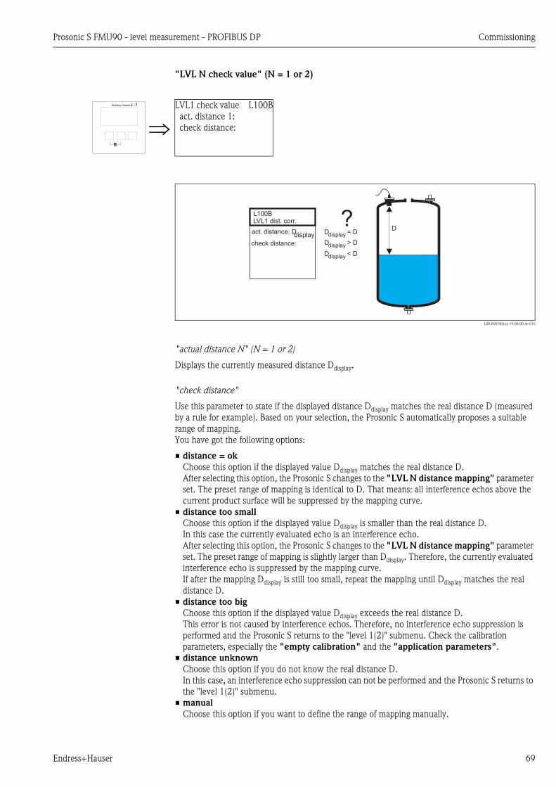
Prosonic S FMU90 - level measurement - PROFIBUS DP Commissioning
Endress+Hauser 69
"LVL N check value" (N = 1 or 2)
L00-FMU90xxx-19-00-00-de-016
"actual distance N" (N = 1 or 2)
Displays the currently measured distance Ddisplay.
"check distance"
Use this parameter to state if the displayed distance Ddisplay matches the real distance D (measured
by a rule for example). Based on your selection, the Prosonic S automatically proposes a suitable
range of mapping.
You have got the following options:
• distance = ok
Choose this option if the displayed value Ddisplay matches the real distance D.
After selecting this option, the Prosonic S changes to the "LVL N distance mapping" parameter
set. The preset range of mapping is identical to D. That means: all interference echos above the
current product surface will be suppressed by the mapping curve.
• distance too small
Choose this option if the displayed value Ddisplay is smaller than the real distance D.
In this case the currently evaluated echo is an interference echo.
After selecting this option, the Prosonic S changes to the "LVL N distance mapping" parameter
set. The preset range of mapping is slightly larger than Ddisplay. Therefore, the currently evaluated
interference echo is suppressed by the mapping curve.
If after the mapping Ddisplay is still too small, repeat the mapping until Ddisplay matches the real
distance D.
• distance too big
Choose this option if the displayed value Ddisplay exceeds the real distance D.
This error is not caused by interference echos. Therefore, no interference echo suppression is
performed and the Prosonic S returns to the "level 1(2)" submenu. Check the calibration
parameters, especially the "empty calibration" and the "application parameters".
• distance unknown
Choose this option if you do not know the real distance D.
In this case, an interference echo suppression can not be performed and the Prosonic S returns to
the "level 1(2)" submenu.
• manual
Choose this option if you want to define the range of mapping manually.
LVL1 check value L100B
act. distance 1:
check distance:
L100BLVL1 dist. corr.
act. distance: DD
display Ddisplay = D
Ddisplay > D
Ddisplay < D
?check distance:
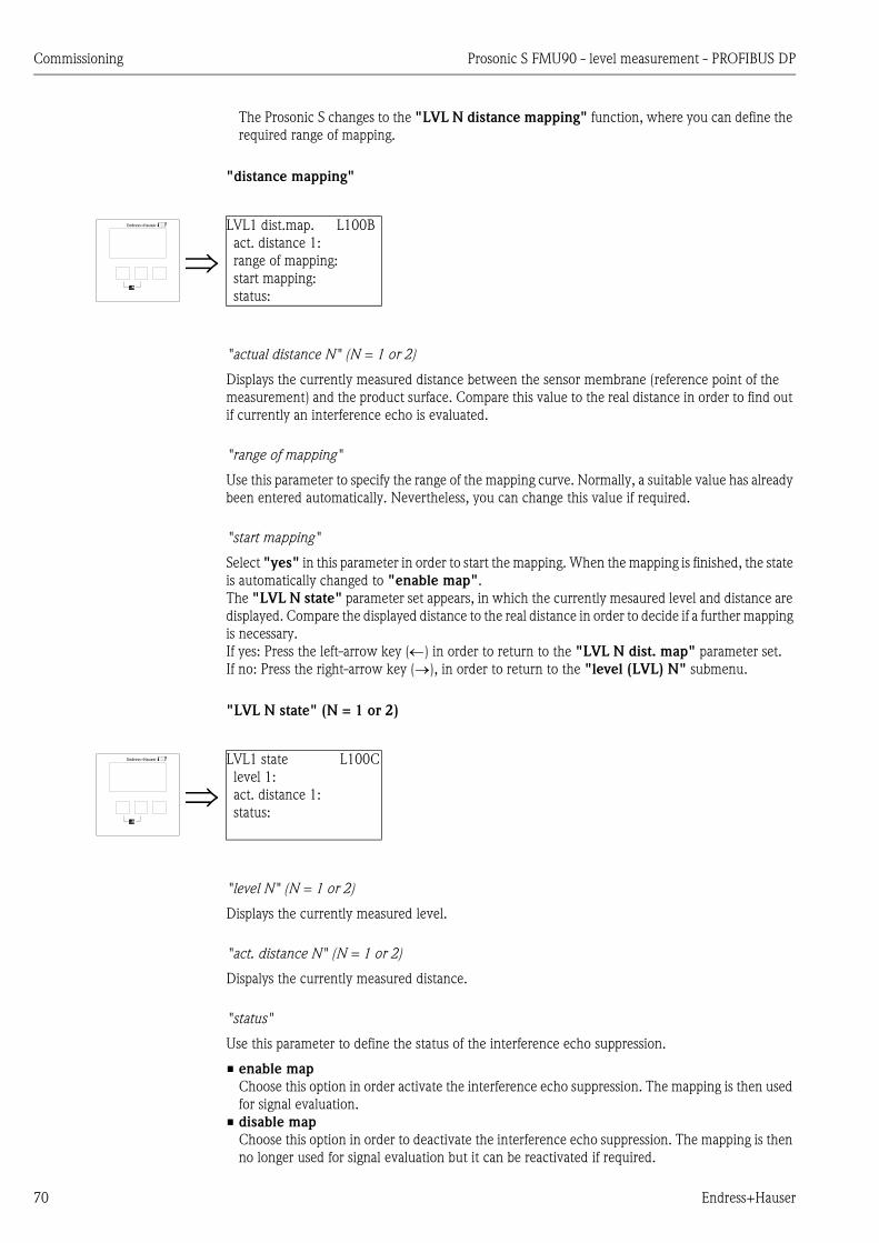
Commissioning Prosonic S FMU90 - level measurement - PROFIBUS DP
70 Endress+Hauser
The Prosonic S changes to the "LVL N distance mapping" function, where you can define the
required range of mapping.
"distance mapping"
"actual distance N" (N = 1 or 2)
Displays the currently measured distance between the sensor membrane (reference point of the
measurement) and the product surface. Compare this value to the real distance in order to find out
if currently an interference echo is evaluated.
"range of mapping"
Use this parameter to specify the range of the mapping curve. Normally, a suitable value has already
been entered automatically. Nevertheless, you can change this value if required.
"start mapping"
Select "yes" in this parameter in order to start the mapping. When the mapping is finished, the state
is automatically changed to "enable map".
The "LVL N state" parameter set appears, in which the currently mesaured level and distance are
displayed. Compare the displayed distance to the real distance in order to decide if a further mapping
is necessary.
If yes: Press the left-arrow key () in order to return to the "LVL N dist. map" parameter set.
If no: Press the right-arrow key (), in order to return to the "level (LVL) N" submenu.
"LVL N state" (N = 1 or 2)
"level N" (N = 1 or 2)
Displays the currently measured level.
"act. distance N" (N = 1 or 2)
Dispalys the currently measured distance.
"status"
Use this parameter to define the status of the interference echo suppression.
• enable map
Choose this option in order activate the interference echo suppression. The mapping is then used
for signal evaluation.
• disable map
Choose this option in order to deactivate the interference echo suppression. The mapping is then
no longer used for signal evaluation but it can be reactivated if required.
LVL1 dist.map. L100B
act. distance 1:
range of mapping:
start mapping:
status:
LVL1 state L100C
level 1:
act. distance 1:
status:

Prosonic S FMU90 - level measurement - PROFIBUS DP Commissioning
Endress+Hauser 71
• delete map
Choose this option in order to delete the mapping. It can not be reactivated again and the
instrument uses the preprogrammed default mapping.
6.2.4 Envelope curve display
After the basic setup an evaluation of the measurement with the aid of the envelope curve is
recommended, ä 129, "Troubleshooting".

Commissioning Prosonic S FMU90 - level measurement - PROFIBUS DP
72 Endress+Hauser
6.3 Configuration of a limit relay
6.3.1 Overview
6.3.2 "relay allocation"
Use this parameter to select the relay you are going to configure.
Selection:
• All relays of the instrument version at hand
! Note!
If a function has already been allocated to one of the relays, the name of this function is displayed
next to the relay number.
Step Parameter set or submenu Parameter Remarks Chapter
1 "relay/controls" menu Select "relay configuration".
2 relay allocation Select a relay. Chap. 6.3.2
3 relay N (N= 1 -6) function 1. Select "limit"
2. Select the measured or calculated value to which the limit refers.
Chap. 6.3.3
4 relay N (N = 1 - 6) limit type Select a limit type. Chap. 6.3.4
switch on point Define the switch on point.
(only available for "limit type" = "standard" or "tendency/speed")
switch off point Define the switch off point.
(only available for "limit type" = "standard" or "tendency/speed")
upper switch point Define the upper switch point.
(only available for "limit type" = "inband" or "out of band")
lower switch point Define the lower switch point.
(only available for "limit type" = "inband" or "out of band")
hysteresis Define the hysteresis.
(only available for "limit type" = "inband" or "out of band")
5 relay N (N = 1 - 6) switch delay Define the switch delay (Default: 0s). Chap. 6.3.5
invert Select if the relay signal is to be inverted (default: no)
error handling Define the reaction of the relay in the case of an error.
relay allocation RX101
relay 1
relay 2
relay 3
relay 4
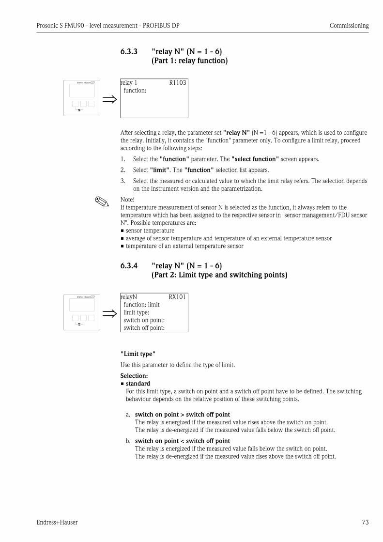
Prosonic S FMU90 - level measurement - PROFIBUS DP Commissioning
Endress+Hauser 73
6.3.3 "relay N" (N = 1 - 6)
(Part 1: relay function)
After selecting a relay, the parameter set "relay N" (N =1 - 6) appears, which is used to configure
the relay. Initially, it contains the "function" parameter only. To configure a limit relay, proceed
according to the following steps:
1. Select the "function" parameter. The "select function" screen appears.
2. Select "limit". The "function" selection list appears.
3. Select the measured or calculated value to which the limit relay refers. The selection depends
on the instrument version and the parametrization.
! Note!
If temperature measurement of sensor N is selected as the function, it always refers to the
temperature which has been assigned to the respective sensor in "sensor management/FDU sensor
N". Possible temperatures are:
• sensor temperature
• average of sensor temperature and temperature of an external temperature sensor
• temperature of an external temperature sensor
6.3.4 "relay N" (N = 1 - 6)
(Part 2: Limit type and switching points)
"Limit type"
Use this parameter to define the type of limit.
Selection:
• standard
For this limit type, a switch on point and a switch off point have to be defined. The switching
behaviour depends on the relative position of these switching points.
a. switch on point > switch off point
The relay is energized if the measured value rises above the switch on point.
The relay is de-energized if the measured value falls below the switch off point.
b. switch on point < switch off point
The relay is energized if the measured value falls below the switch on point.
The relay is de-energized if the measured value rises above the switch off point.
relay 1 R1103
function:
relayN RX101
function: limit
limit type:
switch on point:
switch off point:
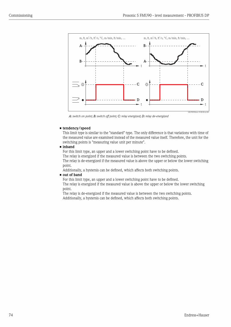
Commissioning Prosonic S FMU90 - level measurement - PROFIBUS DP
74 Endress+Hauser
L00-FMU90xxx-19-00-00-yy-061
A: switch on point; B: switch off point; C: relay energized; D: relay de-energized
• tendency/speed
This limit type is similar to the "standard" type. The only difference is that variations with time of
the measured value are examined instead of the measured value itself. Therefore, the unit for the
switching points is "measuring value unit per minute".
• inband
For this limit type, an upper and a lower switching point have to be defined.
The relay is energized if the measured value is between the two switching points.
The relay is de-energized if the measured value is above the upper or below the lower switching
point.
Additionally, a hystersis can be defined, which affects both switching points.
• out of band
For this limit type, an upper and a lower switching point have to be defined.
The relay is energized if the measured value is above the upper or below the lower switching
point.
The relay is de-energized if the measured value is between the two switching points.
Additionally, a hystersis can be defined, which affects both switching points.
m, ft, m /h, ft /s, °C, m/min, ft/min, …3 3
t
t
A
B
C
D
t
t
B
A
C
D
m, ft, m /h, ft /s, °C, m/min, ft/min, …3 3
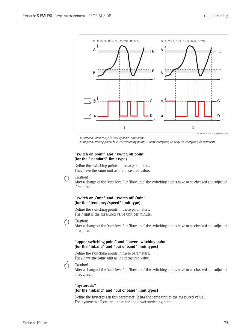
Prosonic S FMU90 - level measurement - PROFIBUS DP Commissioning
Endress+Hauser 75
L00-FMU90xxx-19-00-hfsdjhfjkdfkfhkf00-yy-062
1: "inband" limit relay; 2: "out of band" limit relay
A: upper switching point; B: lower switching point; C: relay energized; D: relay de-energized; E: hysteresis
"switch on point" and "switch off point"
(for the "standard" limit type)
Define the switching points in these parameters.
They have the same unit as the measured value.
" Caution!
After a change of the "unit level" or "flow unit" the switching points have to be checked and adjusted
if required.
"switch on /min" and "switch off /min"
(for the "tendency/speed" limit type)
Define the switching points in these parameters.
Their unit is the measured value unit per minute.
" Caution!
After a change of the "unit level" or "flow unit" the switching points have to be checked and adjusted
if required.
"upper switching point" and "lower switching point"
(for the "inband" and "out of band" limit types)
Define the switching points in these parameters.
They have the same unit as the measured value.
" Caution!
After a change of the "unit level" or "flow unit" the switching points have to be checked and adjusted
if required.
"hysteresis"
(for the "inband" and "out of band" limit types)
Define the hysteresis in this parameter. It has the same unit as the measured value.
The hysteresis affects the upper and the lower swtiching point.
m, ft, m /h, ft /s, °C, m/min, ft/min, …3 3
t
t
A
B
C
D
E
E
m, ft, m /h, ft /s, °C, m/min, ft/min, …3 3
t
t
A
B
C
D
E
E
1 2

Commissioning Prosonic S FMU90 - level measurement - PROFIBUS DP
76 Endress+Hauser
6.3.5 "relay N (N = 1 - 6)"
(Part 3: Relay behavior)
"switch delay"
Use this parameter to specify the switch delay (in seconds).
The relay does not switch immediately after the switch on point has been exceeded but only after
the specified delay.
The measured value must exceed the switch-on point during the entire delay time.
"invert"
Use this parameter to specify if the switching direction of the relay is to be inverted.
Selection:
• no (default)
The switching direction of the relay is not inverted. The relay switches as described in the above
sections.
• yes
The switching direction of the relay is inverted. The states "energized" and "de-energized" are
interchanged as compared to the above description.
"error handling"
Use this parameter to specify the reaction of the relay in the case of an error.
Selection:
• actual value
The relay switches according the the currently measured value (although its reliability is not
ensured).
• hold (default)
The current switching state of the relay is maintained.
• switch on
The relay is energized.
• switch off
The relay is de-energized.
relay X RX104
switch delay:
invert:
error handling:

Prosonic S FMU90 - level measurement - PROFIBUS DP Commissioning
Endress+Hauser 77
6.4 Configuration of an alarm or diagnostic relay
6.4.1 Overview
6.4.2 "relay allocation"
Use this parameter to select the relay you are going to configure.
Selection:
• All relays of the instrument version at hand
! Note!
If a function has already been allocated to one of the relays, the name of this function is displayed
next to the relay number.
Step Parameter set or submenu Parameter Remark Chapter
1 "relay controls" menu Select "relay configuration"
2 relay allocation Select a relay Chap. 6.4.2
3 relay N (N= 1 -6) function 1. Select "alarm/diagnostics"
2. Select
– "alarm relay", if the relay is to indicate an alarm state of the
Prosonic S.1)
– "diagnostics", if the relay is to indicate one or two user selectable
states of the instrument.
Chap. 6.4.3
4 relay N (N = 1 - 6) allocation 1 Select the first instrument state which is to be indicated by the relay.
(only available if "diagnostics" has been selected in the previous function)
Chap. 6.4.4
allocation 2 Select the seccond instrument state which is to be indicated by the relay.
(only available if "diagnsotics" has been selected in the previous function)
5 relay N (N = 1 - 6) invert Select if the relay signal is to be inverted (default: no) Chap. 6.4.5
1) This is the default setting for relay 1.
relay allocation RX101
relay 1
relay 2
relay 3
relay 4

Commissioning Prosonic S FMU90 - level measurement - PROFIBUS DP
78 Endress+Hauser
6.4.3 "relay N" (N = 1 - 6)
(Part 1: relay function)
After selecting a relay, the parameter set "relay N" (N =1 - 6) appears, which is used to configure
the relay. Initially, it contains only the "function" parameter. To configure an alarm relay or
diagnostic relay, proceed according to the following steps:
1. Select the "function" parameter. The "select function" screen appears.
2. Select "alarm/diagnostics". The "function" selection list appears.
3. Select
– "alarm relay", if the relay is to indicate an alarm state of the Prosonic S5).
– "diagnostics" if the relay is to indicate one or two user selectable states of the instrument.
6.4.4 "relay N" (N = 1 - 6)
(Part 2: Allocation of the switching condition)
"allocation 1/2"
A specific instrument state or event can be allocated to each of these parameters. The relay is de-
energized as soon as one of these states or events occurs.
Selection:
• echoloss sensor 1/2/1+2
• defective temperature sensor1/2
• defective external temperature sensor
• Accumulated alarm: defective temperature sensor
• overtemp. sensor 1/2
• Accumulated Alarm: overtemp.
• safety distance channel 1/2
• Accumulated Alarm: safety distance
• pump alarm
• pump operation
relay 1 R1103
function:
5) This is the default setting for relay 1.
relay N RN103
function: diagnostics
allocation 1:
allocation 2:

Prosonic S FMU90 - level measurement - PROFIBUS DP Commissioning
Endress+Hauser 79
6.4.5 "relay N" (N = 1 - 6)
(Part 3: Relay behavior)
"invert" subfunction
Use this parameter to specify if the switching direction of the relay is to be inverted.
Selection:
• no (default)
The switching direction of the relay is not inverted. The relay switches as described in the above
sections.
• yes
The switching direction of the relay is inverted. The states "energized" and "de-energized" are
interchanged as compared to the above description.
6.5 Configuration of a pump control - standard
! Note!
Depending on the order code of the instrument, different functionalities can be configured for the
pump control. The order code of the instrument can be found on the nameplate and in the operating
menu at "system information/device information".
This chapter is only valid for instruments with standard pump control
(FMU90-*1********** and FMU90-*2**********).
For the enhanced pump control see chapter 6.6
(FMU90-*3********** and FMU90-*4**********).
! Note!
The "pump control N" submenus are only present if "pump control" has been selected in "device
properties/operating parameters/controls".
6.5.1 Basic principles
Switch points
The pump control is used to start or stop pumps depending on the measured level. To do this, a
switch-on point and a switch-off point is defined for each pump. Additionally, a relay is assigned to
the pump and the switching is performed by this relay.
Two cases can be distinguished for the swichting behaviour of this relay:
a. Switch-on point > Switch-off point
The pump is switched on if the level rises above the switch-on point (A). It is switched off if
the level drops below the switch-off point (B).
Example: Emptying of a flood control reservoir.
relay N RN104
invert:

Commissioning Prosonic S FMU90 - level measurement - PROFIBUS DP
80 Endress+Hauser
L00-FMU90xxx-19-00-00-yy-051
A: switch-on point; B: switch-off point; C: pump on; D: pump off
b. Switch-on point < Switch-off point
The pump is switched on if the level drops below the switch-on point (A). It is switched off if
the level rises above the switch-off point (B).
Example: Filling of a storage vessel
L00-FMU90xxx-19-00-00-yy-052
A: switch-on point; B: switch-off point; C: pump on; D: pump off
Operating mode
The Prosonic S can control several pumps simultaneously - depending on the number of relays (s.
feature 70 of the product structure). If two or more pumps are applied for one level channel, you
can choose between two different operating modes:
a. Non-alternating pump control
In this mode, each pump is switched according to the switching points allocated to it.
b. Alternating pump control
In this mode, the switching points are not allocated to the individual pumps. Instead, the relays
are switched in a way that ensures uniform usage of all pumps. This is achieved by the
following rules:
1. If the level rises above one of the switch-on points, that relay switches on, which at that
moment has been switched off the longest time. This is not necessarily the relay to which
the switch-on point belongs.
2. If the level drops below one of the switch-off points, that relay switches off, which at that
moment has been switched on the longest time. This is not necessarily the relay to which
the switch-off point belongs.
L
A
B
t
t
C
D
L
A
B
t
t
C
D

Prosonic S FMU90 - level measurement - PROFIBUS DP Commissioning
Endress+Hauser 81
However, there are two restrictions to these rules:
3. Rising of the level above a switch-on point effects switching on of a relay only if the
corresponding switch-off point has been reached before.
4. Dropping of the level below a switch-off points effects switching-off of a relay only if the
corresponding switch-on point has been reached before.
! Note!
If two pumps in the same range are to operate alternately, their switch-on and switch-off points
are identical. This switching response can be achieved by assigning switch points to the second
relay which can never be reached.
Example
In the switching range between 60% and 40%, two pumps should be operated alternately, i.e.
when pump 1 in running, pump 2 is switched off and vice versa. These relays are programmed
as follows:
– Relay 1: switch-on point: 60%; switch-off point: 40%
– Relay 2: switch-on point: e.g. 160%; switch-off point: e.g. 120%.
L00-FMU90xxx-19-00-00-yy-053
1: Alternating pump control; that pump is switched on (switched off), which has been switched off (switched on) the
longest time.
2: Non-alternating pump control; each switching point is allocated to a different pump.
A: switch-on point of the pump; B: switch-off point of the pump; C: pump on; D: pump off;
P1
P1
P1
P2
P2
P3
P3
P2 P3
t
L
P1 P2 P3A
A B
A B
B
C
C
C
C
C
C
D
D
D
D
D
1
2
D
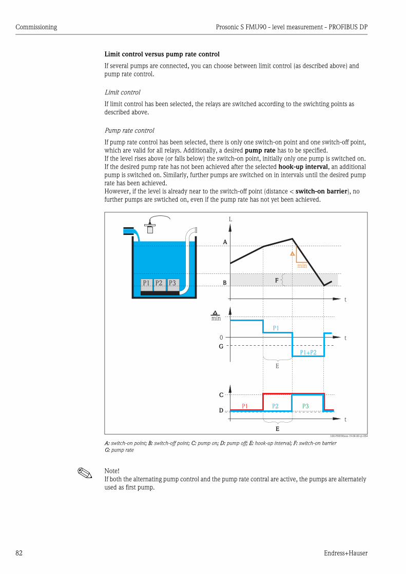
Commissioning Prosonic S FMU90 - level measurement - PROFIBUS DP
82 Endress+Hauser
Limit control versus pump rate control
If several pumps are connected, you can choose between limit control (as described above) and
pump rate control.
Limit control
If limit control has been selected, the relays are switched according to the swichting points as
described above.
Pump rate control
If pump rate control has been selected, there is only one switch-on point and one switch-off point,
which are valid for all relays. Additionally, a desired pump rate has to be specified.
If the level rises above (or falls below) the switch-on point, initially only one pump is switched on.
If the desired pump rate has not been achieved after the selected hook-up interval, an additional
pump is switched on. Similarly, further pumps are switched on in intervals until the desired pump
rate has been achieved.
However, if the level is already near to the switch-off point (distance < switch-on barrier), no
further pumps are swtiched on, even if the pump rate has not yet been achieved.
L00-FMU90xxx-19-00-00-yy-054
A: switch-on point; B: switch-off point; C: pump on; D: pump off; E: hook-up interval; F: switch-on barrier
G: pump rate
! Note!
If both the alternating pump control and the pump rate contral are active, the pumps are alternately
used as first pump.
P1
P1+P2
P1 P2 P3
P1
P2 P3
0
t
t
t
min
min
L
A
B
C
D
E
E
F
G
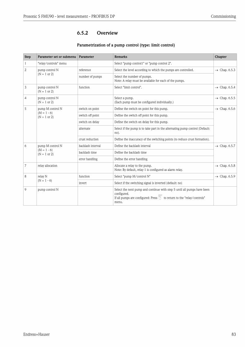
Prosonic S FMU90 - level measurement - PROFIBUS DP Commissioning
Endress+Hauser 83
6.5.2 Overview
Parametrization of a pump control (type: limit control)
Step Parameter set or submenu Parameter Remarks Chapter
1 "relay/controls" menu Select "pump control1" or "pump control 2".
2 pump control N
(N = 1 or 2)
reference Select the level according to which the pumps are controlled. Chap. 6.5.3
number of pumps Select the number of pumps.
Note: A relay must be available for each of the pumps.
3 pump control N
(N = 1 or 2)
function Select "limit control". Chap. 6.5.4
4 pump control N
(N = 1 or 2)
Select a pump.
(Each pump must be configured individually.)
Chap. 6.5.5
5 pump M control N
(M = 1 - 6)
(N = 1 or 2)
switch on point Define the switch on point for this pump. Chap. 6.5.6
switch off point Define the switch off point for this pump.
switch on delay Define the switch on delay for this pump.
alternate Select if the pump is to take part in the alternating pump control (Default:
no).
crust reduction Define the inaccuracy of the switching points (to reduce crust formation).
6 pump M control N
(M = 1 - 6)
(N = 1 or 2)
backlash interval Define the backlash interval Chap. 6.5.7
backlash time Define the backlash time
error handling Define the error handling
7 relay allocation Allocate a relay to the pump.
Note: By default, relay 1 is configured as alarm relay.
Chap. 6.5.8
8 relay N
(N = 1 - 6)
function Select "pump M/control N" Chap. 6.5.9
invert Select if the switching signal is inverted (default: no)
9 pump control N Select the next pump and continue with step 5 until all pumps have been
configured.
If all pumps are configured: Press to return to the "relay/controls"
menu.

Commissioning Prosonic S FMU90 - level measurement - PROFIBUS DP
84 Endress+Hauser
Parametrization of a pump control (type: pump rate control)
Step Parameter set or submenu Parameter Remarks Chapter
1 "relay/controls" submenu Select "pump control 1" or "pump control 2".
2 pump control N
(N = 1 or 2)
refernece Select the level according to which the pumps are controlled. Chap. 6.5.3
number of pumps Select the number of pumps.
Note: A relay must be available for each of the pumps.
3 pump control N
(N = 1 or 2)
function Select "rate control" Chap. 6.5.4
4 pump control N
(N = 1 or 2)
switch on point Define the switch on point. Chap. 6.5.10
switch off point Define the switch off point.
min. pumprate/min Dfine the minimum pump rate.
crust reduction Define the inaccuracy for the switching points (to reduce crust formation).
switch on border Define the switch on border.
hook up interval Define the hook-up interval.
alternate Select if an alternating pump control is to be performed.
5 pump control N
(N = 1 or 2)
Select a pump.
(The following parameters must be configured for each pump individually.)
Chap. 6.5.5
6 pumpe M control N
(M = 1 - 6)
(N = 1 or 2)
switch on delay Define the switch on delay. Chap. 6.5.11
backlash interval Define the backlash interval.
backlash time Define the backlash time.
error handling Define the error handling.
7 relay allocation Allocate a relay to the pump.
Note: By default, relay 1 is configured as alarm relay.
Chap. 6.5.8
8 relay N
(N = 1 - 6)
function Select "pump M/control N". Chap. 6.5.9
invert Select if the switching signal is inverted (default: no).
9 pump control N Select the next pump and continue with step 6 until all pumps have been
configured.
If all pumps are configured: Press to return to the "relay/controls"
menu.

Prosonic S FMU90 - level measurement - PROFIBUS DP Commissioning
Endress+Hauser 85
6.5.3 "pump control N" (N = 1 or 2)
"reference"
Defines the level channel to which the pump control refers.
Selection:
• none (default)
• level 1
• level 2 (for instrument versions with 2 level inputs)
"number of pumps"
Defines the number of pumps participating in the pump control. At the end of the configuration
procedure a relay must be allocated to each of the pumps ("relay allocation" parameter set).
• Range of values : 1 ... 6 (depending on the number of relays)
• Default: 1
6.5.4 "pump control N" (N = 1 or 2)
"function"
Determines the type of pump control.
Selection:
• limit control (Default)
Each pump has its own switch-on point and switch-off point
• rate control
There is only one switch-on point and one switch-off point for all pumps. If the switch-on point
has been exceeded, several pumps are switched on in intervals until the defined pumprate is
obtained. For details refer to the chapter "Limit control and rate control".
pump control R1300
reference:
number of pumps:
pump control R1301
function:
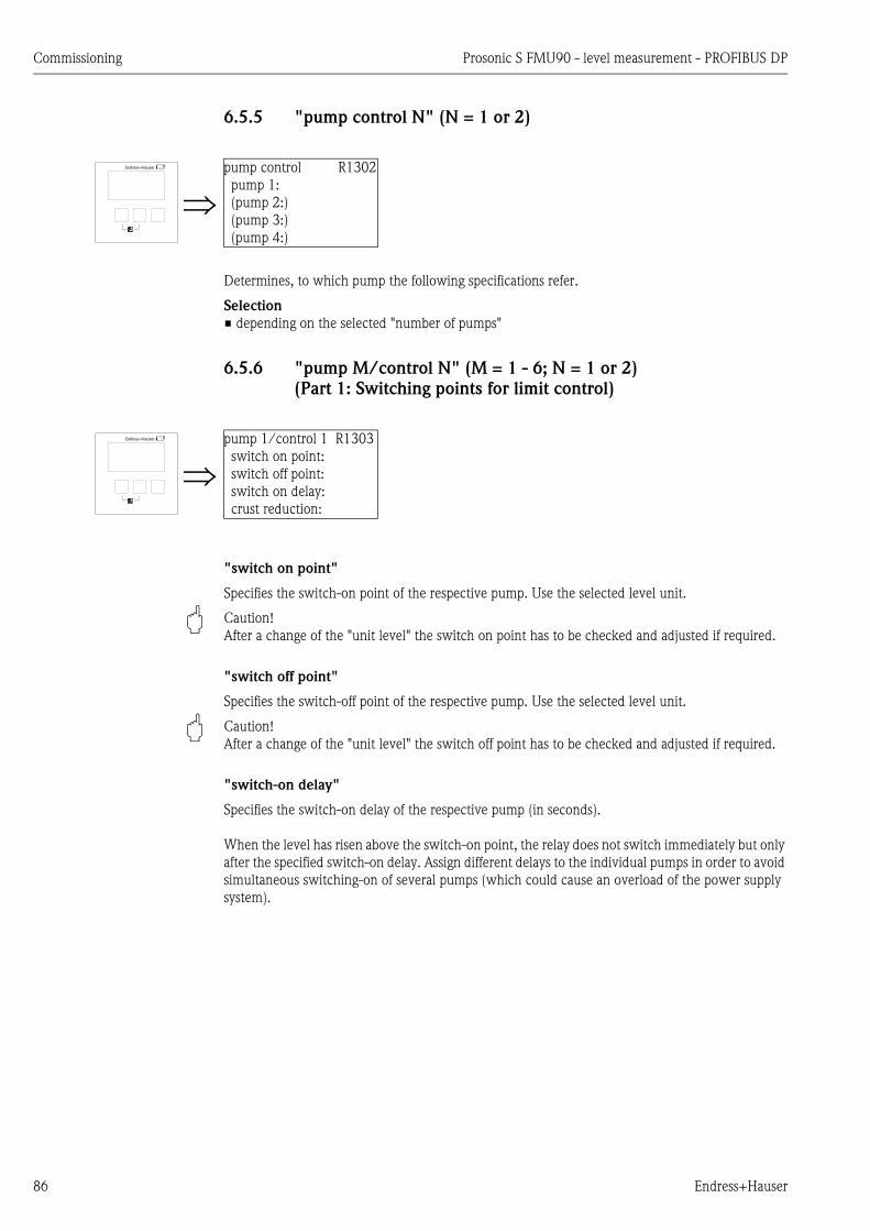
Commissioning Prosonic S FMU90 - level measurement - PROFIBUS DP
86 Endress+Hauser
6.5.5 "pump control N" (N = 1 or 2)
Determines, to which pump the following specifications refer.
Selection
• depending on the selected "number of pumps"
6.5.6 "pump M/control N" (M = 1 - 6; N = 1 or 2)
(Part 1: Switching points for limit control)
"switch on point"
Specifies the switch-on point of the respective pump. Use the selected level unit.
" Caution!
After a change of the "unit level" the switch on point has to be checked and adjusted if required.
"switch off point"
Specifies the switch-off point of the respective pump. Use the selected level unit.
" Caution!
After a change of the "unit level" the switch off point has to be checked and adjusted if required.
"switch-on delay"
Specifies the switch-on delay of the respective pump (in seconds).
When the level has risen above the switch-on point, the relay does not switch immediately but only
after the specified switch-on delay. Assign different delays to the individual pumps in order to avoid
simultaneous switching-on of several pumps (which could cause an overload of the power supply
system).
pump control R1302
pump 1:
(pump 2:)
(pump 3:)
(pump 4:)
pump 1/control 1 R1303
switch on point:
switch off point:
switch on delay:
crust reduction:
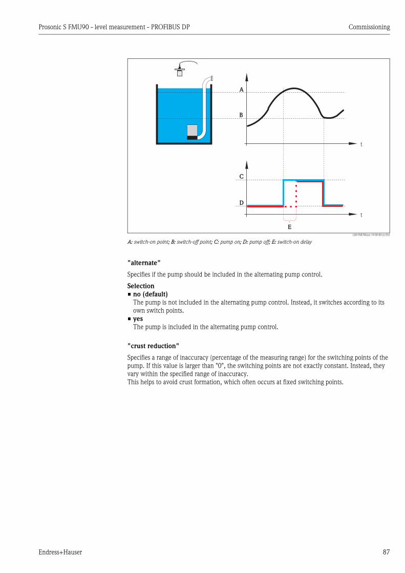
Prosonic S FMU90 - level measurement - PROFIBUS DP Commissioning
Endress+Hauser 87
L00-FMU90xxx-19-00-00-yy-055
A: switch-on point; B: switch-off point; C: pump on; D: pump off; E: switch-on delay
"alternate"
Specifies if the pump should be included in the alternating pump control.
Selection
• no (default)
The pump is not included in the alternating pump control. Instead, it switches according to its
own switch points.
• yes
The pump is included in the alternating pump control.
"crust reduction"
Specifies a range of inaccuracy (percentage of the measuring range) for the switching points of the
pump. If this value is larger than "0", the switching points are not exactly constant. Instead, they
vary within the specified range of inaccuracy.
This helps to avoid crust formation, which often occurs at fixed switching points.
t
t
A
B
C
D
E

Commissioning Prosonic S FMU90 - level measurement - PROFIBUS DP
88 Endress+Hauser
L00-FMU90xxx-19-00-00-yy-056
A: switch-on point; B: switch-off point; C: pump on; D: pump off; E: inaccuracy ("crust reduction")
6.5.7 "pump M/control N" (M = 1 - 6, N = 1 or 2)
(Part 2: Switching behavior for limit control)
"backlash interval" and "backlash time"
Use these parameters if, you want to empty a vessel beyond the switch-off point in regular intervals.
The "backlash interval" determines after which time this extended pumping will occur.
The "backlash time" determines how long this additional pumping lasts.
L
t
t
A
B
C
D
E
E
pumpM/controlN RN304
backl. interval:
backlash time:
error handling:
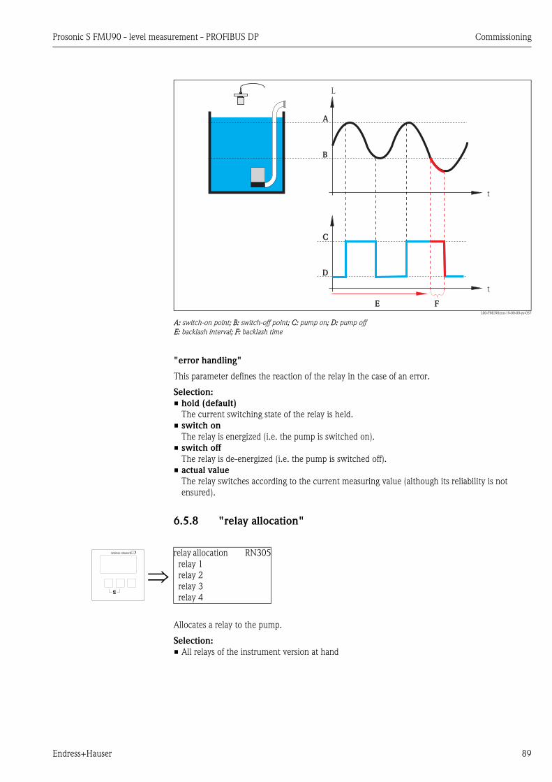
Prosonic S FMU90 - level measurement - PROFIBUS DP Commissioning
Endress+Hauser 89
L00-FMU90xxx-19-00-00-yy-057
A: switch-on point; B: switch-off point; C: pump on; D: pump off
E: backlash interval; F: backlash time
"error handling"
This parameter defines the reaction of the relay in the case of an error.
Selection:
• hold (default)
The current switching state of the relay is held.
• switch on
The relay is energized (i.e. the pump is switched on).
• switch off
The relay is de-energized (i.e. the pump is switched off).
• actual value
The relay switches according to the current measuring value (although its reliability is not
ensured).
6.5.8 "relay allocation"
Allocates a relay to the pump.
Selection:
• All relays of the instrument version at hand
t
t
L
A
B
C
D
E F
relay allocation RN305
relay 1
relay 2
relay 3
relay 4
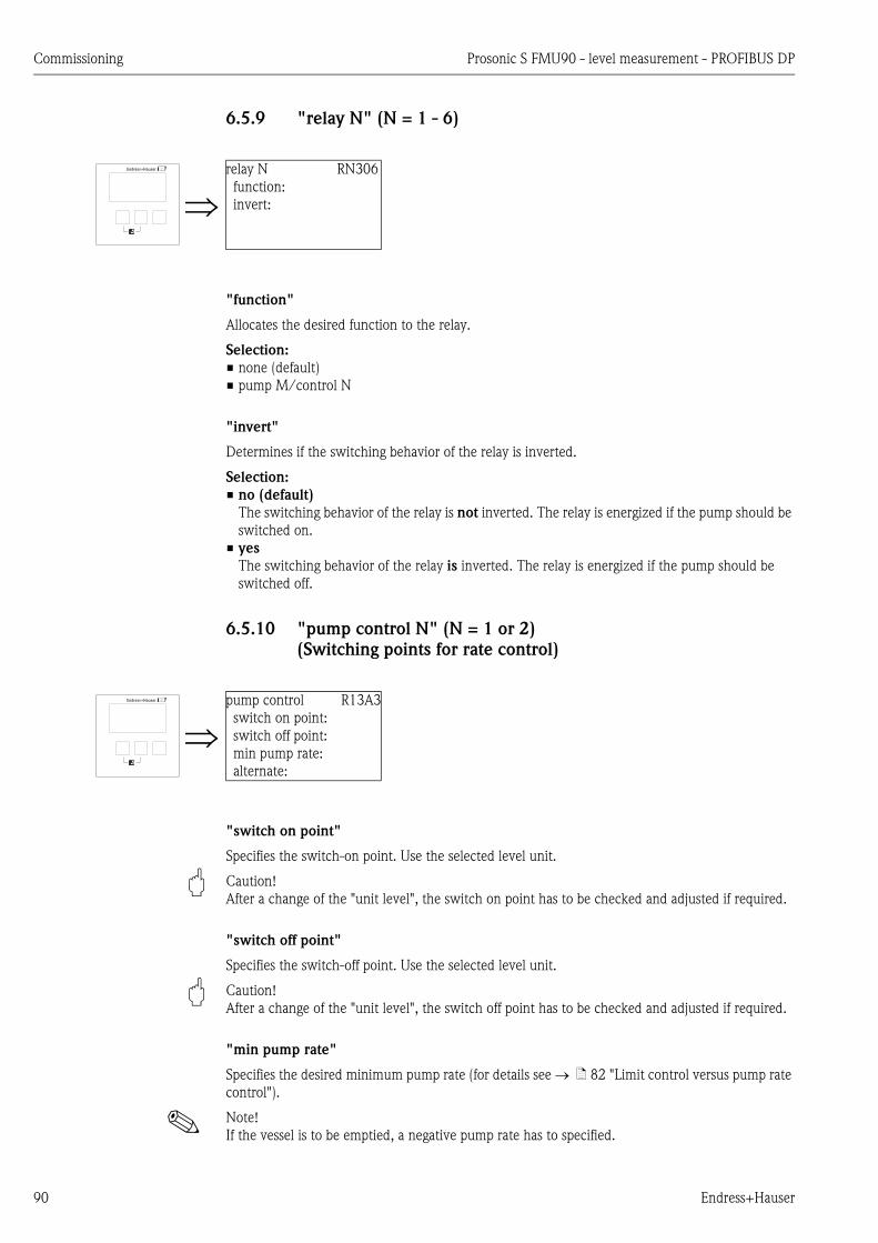
Commissioning Prosonic S FMU90 - level measurement - PROFIBUS DP
90 Endress+Hauser
6.5.9 "relay N" (N = 1 - 6)
"function"
Allocates the desired function to the relay.
Selection:
• none (default)
• pump M/control N
"invert"
Determines if the switching behavior of the relay is inverted.
Selection:
• no (default)
The switching behavior of the relay is not inverted. The relay is energized if the pump should be
switched on.
• yes
The switching behavior of the relay is inverted. The relay is energized if the pump should be
switched off.
6.5.10 "pump control N" (N = 1 or 2)
(Switching points for rate control)
"switch on point"
Specifies the switch-on point. Use the selected level unit.
" Caution!
After a change of the "unit level", the switch on point has to be checked and adjusted if required.
"switch off point"
Specifies the switch-off point. Use the selected level unit.
" Caution!
After a change of the "unit level", the switch off point has to be checked and adjusted if required.
"min pump rate"
Specifies the desired minimum pump rate (for details see ä 82 "Limit control versus pump rate
control").
! Note!
If the vessel is to be emptied, a negative pump rate has to specified.
relay N RN306
function:
invert:
pump control R13A3
switch on point:
switch off point:
min pump rate:
alternate:

Prosonic S FMU90 - level measurement - PROFIBUS DP Commissioning
Endress+Hauser 91
"crust reduction" subfunction
Specifies a range of inaccuracy (percentage of the measuring range) for the switching points. If this
value is larger then "0", the switching points are not exactly constant. Instead, they vary within the
specified range of inaccuracy.
This helps to avoid crust formation, which often occurs at fixed switching points.
L00-FMU90xxx-19-00-00-yy-056
A: switch-on point; B: switch-off point; C: pump onD: pump off; E: inaccuracy ("crust reduction")
"switch on border"
Specifies the switch-on border for the rate control (for details ä 82 "Limit control versus pump
rate control").
"hook up interval"
Specifies the time interval between the switching-on of the different pumps (for details ä 82
"Limit control versus pump rate control").
"alternate"
Determines if an alternating pump control is to be performed.
L
t
t
A
B
C
D
E
E

Commissioning Prosonic S FMU90 - level measurement - PROFIBUS DP
92 Endress+Hauser
6.5.11 "pump M/control N" (M = 1 - 6, N = 1 or 2)
(Switching behavior for rate control)
"switch-on delay"
see ä 86
"backlash interval" and "backlash time"
see ä 88
"error handling"
see ä 89
pump control RN304
switch-on delay:
backlash interval:
backlash time:
error handling:

Prosonic S FMU90 - level measurement - PROFIBUS DP Commissioning
Endress+Hauser 93
6.6 Configuration of a pump control - enhanced
! Note!
Depending on the order code of the instrument, different functionalities can be configured for the
pump control. The order code of the instrument can be found on the nameplate and in the operating
menu at "system information/device information".
This chapter is only valid for instruments with enhanced pump control
(FMU90-*3********** and FMU90-*4**********).
For the standard pump control see chapter 6.5
(FMU90-*1********** and FMU90-*2**********).
! Note!
The "pump control N" submenus are only present if "pump control" has been selected in "device
properties/operating parameters/controls".
6.6.1 Basic principles
The pump control is used to start or stop pumps depending on the measured level. Up to two pump
controls can be defined. One or more pumps can be allocated to each pump control. The pumps are
switched on and off by the relays of the Prosonic S.
The switching behavior depends on:
• the selected "function"
• the selected type of "load control" (only relevant for alternating pump control)
Functions "limit simple" and "limit parallel"
For these functions, a switch-on point and a switch-off point is defined for each pump. The
switching behaviour depends on the relative position of these two switching points:
a. Switch-on point > Switch-off point ("Emptying")
The pump is switched on if the level rises above the switch-on point (A). It is switched off if
the level drops below the switch-off point (B).
b. Switch-on point < Switch-off point ("Filling")
The pump is switched on if the level drops below the switch-on point (A). It is switched off if
the level rises above the switch-off point (B).
L00-FMU90xxx-19-00-00-yy-052
1: "Emptying" (switch-on point > switch-off point); 2: "Filling" (switch-on point < switch-off point)
A: switch-on point; B: switch-off point; C: pump on; D: pump off
L
A
B
t
t
C
D
L
A
B
t
t
C
D
1 2

Commissioning Prosonic S FMU90 - level measurement - PROFIBUS DP
94 Endress+Hauser
! Note!
If several pumps are allocated to a pump control, the switching direction of all these pumps must
be the same. Mixing of "filling" and "emptying" is not allowed.
The difference between "limit simple" and "limit parallel" relates to the control of more than one
pump:
• limit simple (A)
With this function, only one pump can be running at a time. Before a pump is switched on, the
previously running pumpt is switched off automatically. Details depend on the relative position of
the switching points, especially on the fact if the switching ranges of different pumps are
overlapping. (Refer to the example in the diagram below).
• limit parallel (B)
With this function, several pumps can be switched on at the same time.
Example ("Emptying" with three pumps)
L00-FMU90xxx-19-00-00-yy-107
A: "limit simple"; B: "limit parallel"
1: Separated switching ranges; 2: Overlapping switching ranges;
P1on, P2on, P3on: switch-off points for the pumps P1, P2 and P3
P1off, P2off, P3off: switch-off points for the pumps P1, P2 and P3
P2
t
t
L
P3off
P3on
P2off
P2on
P1off
P1on
P1
t
P3
t
t
t
t
on
on
on
off
off
off
P2
t
t
L
P3off,P2 P1off, off
P3on
P2on
P1on
P1
t
P3
t
t
t
t
on
on
on
off
off
off
A
B P2
P1
P3
on
on
on
off
off
off
P2
P1
P3
on
on
on
1 2

Prosonic S FMU90 - level measurement - PROFIBUS DP Commissioning
Endress+Hauser 95
Function "pump rate control"
If pump rate control has been selected, there is only one switch-on point and one switch-off point,
which are valid for all relays. Additionally, a desired pump rate has to be specified.
If the level rises above (or falls below) the switch-on point, initially only one pump is switched on.
If the desired pump rate has not been achieved after the selected hook-up interval, an additional
pump is switched on. Similarly, further pumps are switched on in intervals until the desired pump
rate has been achieved.
However, if the level is already near to the switch-off point (distance < switch-on barrier), no
further pumps are swtiched on, even if the pump rate has not yet been achieved.
L00-FMU90xxx-19-00-00-yy-054
A: switch-on point; B: switch-off point; C: pump on; D: pump off; E: hook-up interval; F: switch-on barrier
G: pump rate
Alternating pump control
Optionally, a number of pumps can be allocated to the alternating pump control. In this mode, the
switching points are no longer allocated to the individual pumps. Instead, a desired degree of use
must be defined for each pump (e.g. equal usage of all pumps).
If the level rises above (or falls below) the switch-on point and a pump has to be switched on, the
Prosonic S selects the pump according to an algorithm which ensures that in the course of time the
desired degrees of use are obtained for all pumps.
The same is valid for the switching-off of pumps.
! Note!
For the limit control (simple or parallel) it can be defined for each pump individually if it is to take
part in the alternating pump control.
For pump rate control, it is only possible to allocate all pumps or no pump to the alternating pump
control.
P1
P1+P2
P1 P2 P3
P1
P2 P3
0
t
t
t
min
min
L
A
B
C
D
E
E
F
G

Commissioning Prosonic S FMU90 - level measurement - PROFIBUS DP
96 Endress+Hauser
6.6.2 Basic setup
Overview: Parametrization of a limit control (simple/parallel)
Step Parameter set or submenu Parameter Remarks page
1 "relay/controls" menu 1. Select "pump control1" or "pump control 2".
2. Select "basic setup".
2 pump control N
(N = 1 or 2)
reference Select the level according to which the pumps are controlled. 98
number of pumps Select the number of pumps.
Note: A relay must be available for each pump.
98
standby pump1) Define, if one of the pumps is to be a standby pump. 98
reset Restarts an existing pump control; is not used during the parametrization. 98
3 pump control N
(N = 1 or 2)
function Select "rate control". 99
load control Select the type of load control (only relevant for alternating pump control) 99
4 pump control N
(N = 1 or 2)
Select a pump.
(Each pump must be configured individually.)
5 pump M control N
(M = 1 - 6)
(N = 1 or 2)
switch on point Define the switch on point for this pump. 100
switch off point Define the switch off point for this pump. 100
switch on delay Define the switch on delay for this pump. 100
alternate Select if the pump is to take part in the alternating pump control (Default:
no).
101
degree of use Define the desired degree of use (percentage) for this pump;
(only relevant for alternating pump control)
101
max. use time Define the maximum use time for this pump
(only relevant for alternating pump control with "load control" =
"starts+time")
101
crust reduction Define the inaccuracy of the switching points (to reduce crust formation). 101
6 pump M control N
(M = 1 - 6)
(N = 1 or 2)
backlash interval Define the backlash interval. 102
backlash time Define the backlash time. 102
error handling Define the error handling. 102
7 pump M control N
(M = 1 - 6)
(N = 1 or 2)
pump feedback Select the digital input used for pump feedback. 103
feedback delay Define the time interval in which a feedback is required. 103
feedback meaning Define the meaning of the pump feedback. 103
8 relay allocation Allocate a relay to the pump.
Note: By default, relay 1 is configured as alarm relay.
9 relay N
(N = 1 - 6)
function Select "pump M/control N" 104
invert Select if the switching signal is inverted (default: no) 104
10 pump control N Select the next pump and continue with step 5 until all pumps have been
configured.
If all pumps are configured: Press to return to the "relay/controls" menu.
1) only for instruments with external limit switches; the stand-by pump always is the last of the M pumps.
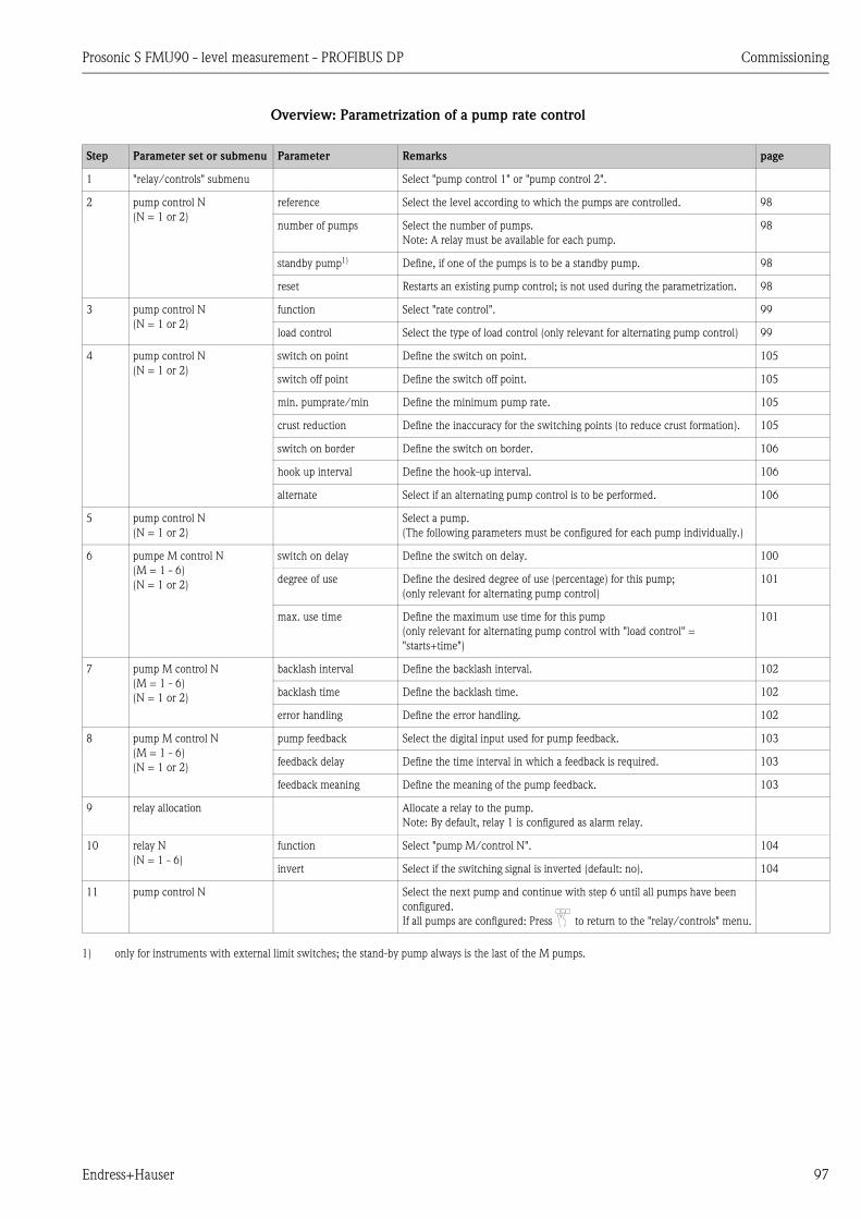
Prosonic S FMU90 - level measurement - PROFIBUS DP Commissioning
Endress+Hauser 97
Overview: Parametrization of a pump rate control
Step Parameter set or submenu Parameter Remarks page
1 "relay/controls" submenu Select "pump control 1" or "pump control 2".
2 pump control N
(N = 1 or 2)
reference Select the level according to which the pumps are controlled. 98
number of pumps Select the number of pumps.
Note: A relay must be available for each pump.
98
standby pump1) Define, if one of the pumps is to be a standby pump. 98
reset Restarts an existing pump control; is not used during the parametrization. 98
3 pump control N
(N = 1 or 2)
function Select "rate control". 99
load control Select the type of load control (only relevant for alternating pump control) 99
4 pump control N
(N = 1 or 2)
switch on point Define the switch on point. 105
switch off point Define the switch off point. 105
min. pumprate/min Define the minimum pump rate. 105
crust reduction Define the inaccuracy for the switching points (to reduce crust formation). 105
switch on border Define the switch on border. 106
hook up interval Define the hook-up interval. 106
alternate Select if an alternating pump control is to be performed. 106
5 pump control N
(N = 1 or 2)
Select a pump.
(The following parameters must be configured for each pump individually.)
6 pumpe M control N
(M = 1 - 6)
(N = 1 or 2)
switch on delay Define the switch on delay. 100
degree of use Define the desired degree of use (percentage) for this pump;
(only relevant for alternating pump control)
101
max. use time Define the maximum use time for this pump
(only relevant for alternating pump control with "load control" =
"starts+time")
101
7 pump M control N
(M = 1 - 6)
(N = 1 or 2)
backlash interval Define the backlash interval. 102
backlash time Define the backlash time. 102
error handling Define the error handling. 102
8 pump M control N
(M = 1 - 6)
(N = 1 or 2)
pump feedback Select the digital input used for pump feedback. 103
feedback delay Define the time interval in which a feedback is required. 103
feedback meaning Define the meaning of the pump feedback. 103
9 relay allocation Allocate a relay to the pump.
Note: By default, relay 1 is configured as alarm relay.
10 relay N
(N = 1 - 6)
function Select "pump M/control N". 104
invert Select if the switching signal is inverted (default: no). 104
11 pump control N Select the next pump and continue with step 6 until all pumps have been
configured.
If all pumps are configured: Press to return to the "relay/controls" menu.
1) only for instruments with external limit switches; the stand-by pump always is the last of the M pumps.
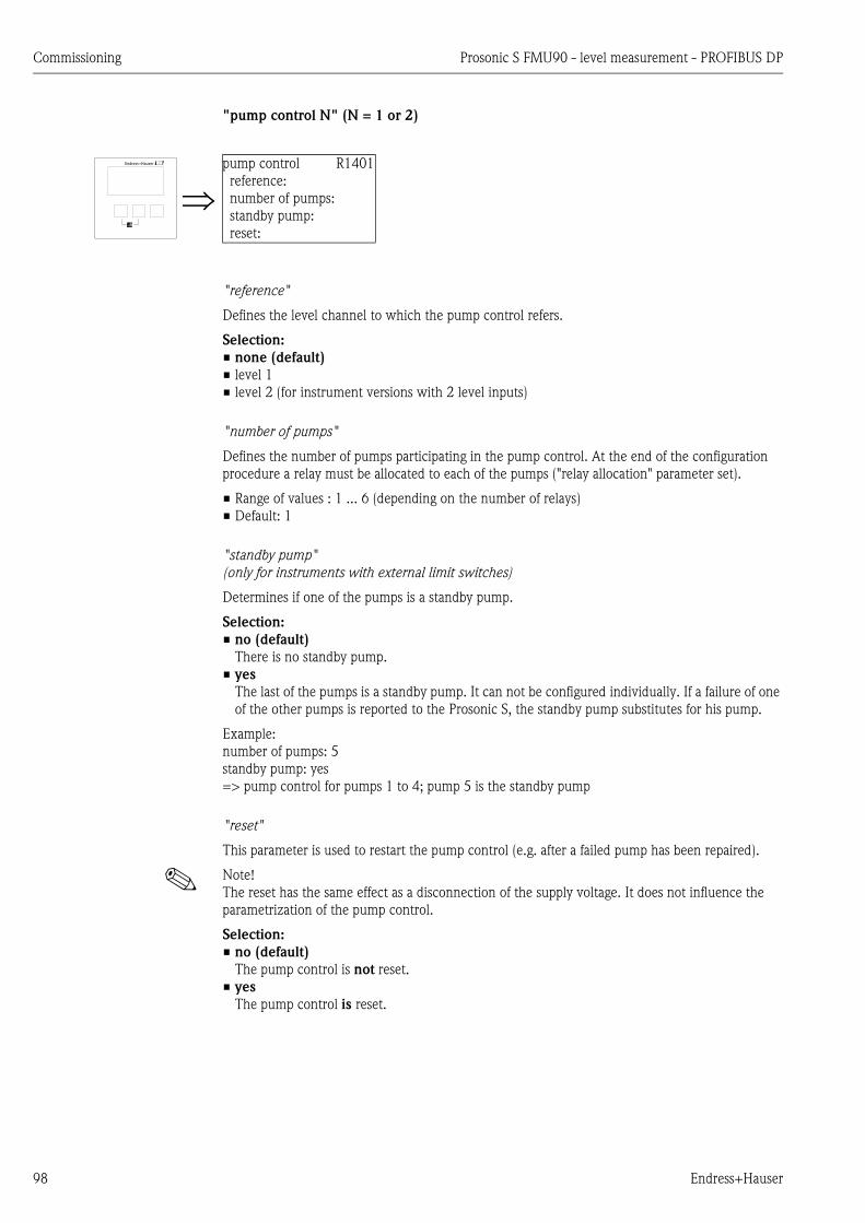
Commissioning Prosonic S FMU90 - level measurement - PROFIBUS DP
98 Endress+Hauser
"pump control N" (N = 1 or 2)
"reference"
Defines the level channel to which the pump control refers.
Selection:
• none (default)
• level 1
• level 2 (for instrument versions with 2 level inputs)
"number of pumps"
Defines the number of pumps participating in the pump control. At the end of the configuration
procedure a relay must be allocated to each of the pumps ("relay allocation" parameter set).
• Range of values : 1 ... 6 (depending on the number of relays)
• Default: 1
"standby pump"
(only for instruments with external limit switches)
Determines if one of the pumps is a standby pump.
Selection:
• no (default)
There is no standby pump.
• yes
The last of the pumps is a standby pump. It can not be configured individually. If a failure of one
of the other pumps is reported to the Prosonic S, the standby pump substitutes for his pump.
Example:
number of pumps: 5
standby pump: yes
=> pump control for pumps 1 to 4; pump 5 is the standby pump
"reset"
This parameter is used to restart the pump control (e.g. after a failed pump has been repaired).
! Note!
The reset has the same effect as a disconnection of the supply voltage. It does not influence the
parametrization of the pump control.
Selection:
• no (default)
The pump control is not reset.
• yes
The pump control is reset.
pump control R1401
reference:
number of pumps:
standby pump:
reset:

Prosonic S FMU90 - level measurement - PROFIBUS DP Commissioning
Endress+Hauser 99
"pump control N" (N = 1 or 2)
"function"
Determines the type of pump control.
Selection:
• limit parallel (Default)
Each pump has its own switch-on point and switch-off point. Several pumps can be running at
the same time.
• limit simple
Each pump has its own switch-on point and switch-off point. Only one pump can be running at
a time.
• rate control
There is only one switch-on point and one switch-off point for all pumps. If the switch-on point
has been exceeded, several pumps are switched on in intervals until the defined pumprate is
obtained. For details refer to the chapter "Limit control and rate control".
"load control"
Determines, how the load of the pumps is measured for the alternating pump control.
Selection:
• in order
– If a pump is to be switched on, the Prosonic S selects the pump which currently has been idle
longer than any other pump.
– If a pump is to be switched off, the Prosonic S selects the pump which currently has been
running longer than any other pump.
• time of use
The total running time is considered for each pump.
• starts (default)
The number of starts is considered for each pump, irrespective of the time the pump has been
running after each start.
• starts+time
Identical to the option "starts".
Additionally, a maximum use time is defined for each pump. After it has been running for this
time, a pump is automatically replaced by another pump.
"pump control N" (N = 1 or 2)
Determines, to which pump the following specifications refer.
Selection
• depending on the selected "number of pumps"
pump control R1402
function:
load control:
pump control R1302
pump 1:
(pump 2:)
(pump 3:)
(pump 4:)
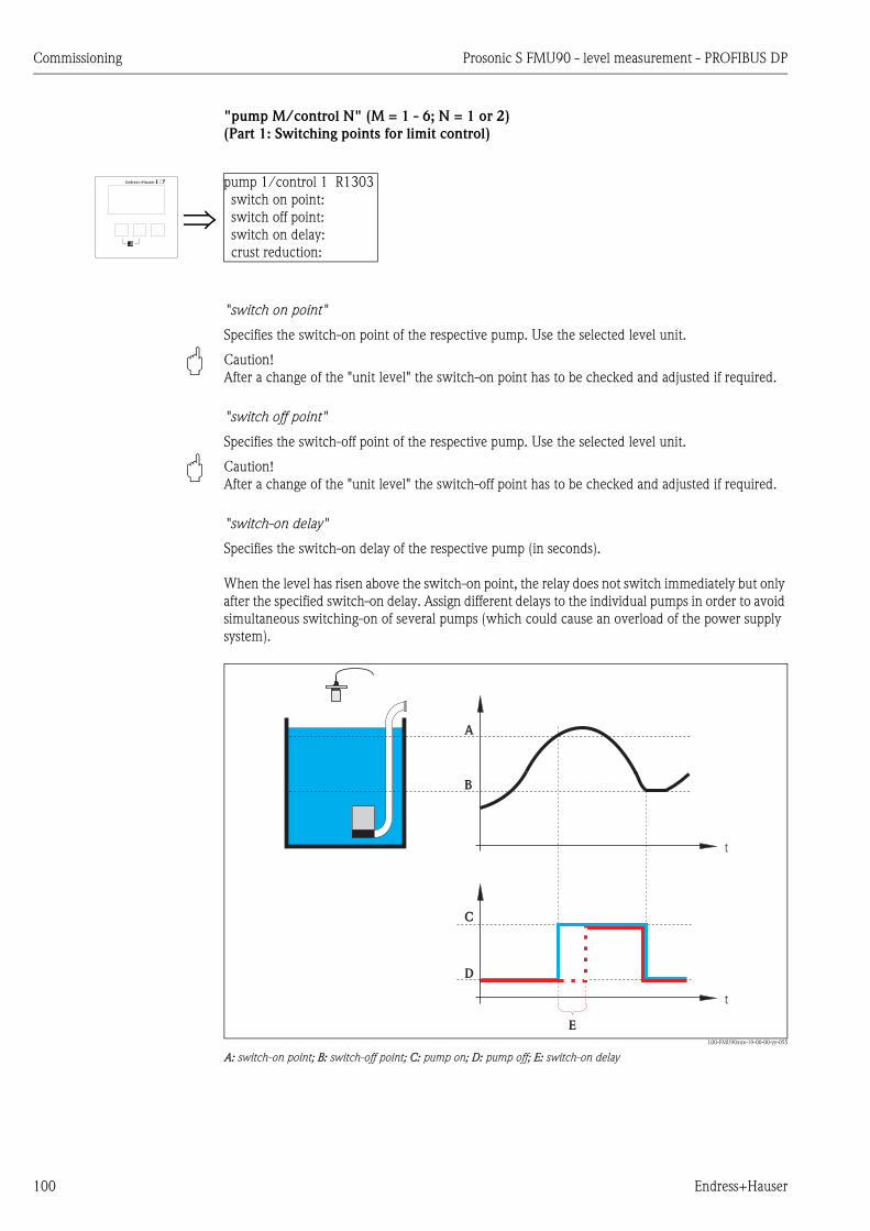
Commissioning Prosonic S FMU90 - level measurement - PROFIBUS DP
100 Endress+Hauser
"pump M/control N" (M = 1 - 6; N = 1 or 2)
(Part 1: Switching points for limit control)
"switch on point"
Specifies the switch-on point of the respective pump. Use the selected level unit.
" Caution!
After a change of the "unit level" the switch-on point has to be checked and adjusted if required.
"switch off point"
Specifies the switch-off point of the respective pump. Use the selected level unit.
" Caution!
After a change of the "unit level" the switch-off point has to be checked and adjusted if required.
"switch-on delay"
Specifies the switch-on delay of the respective pump (in seconds).
When the level has risen above the switch-on point, the relay does not switch immediately but only
after the specified switch-on delay. Assign different delays to the individual pumps in order to avoid
simultaneous switching-on of several pumps (which could cause an overload of the power supply
system).
L00-FMU90xxx-19-00-00-yy-055
A: switch-on point; B: switch-off point; C: pump on; D: pump off; E: switch-on delay
pump 1/control 1 R1303
switch on point:
switch off point:
switch on delay:
crust reduction:
t
t
A
B
C
D
E
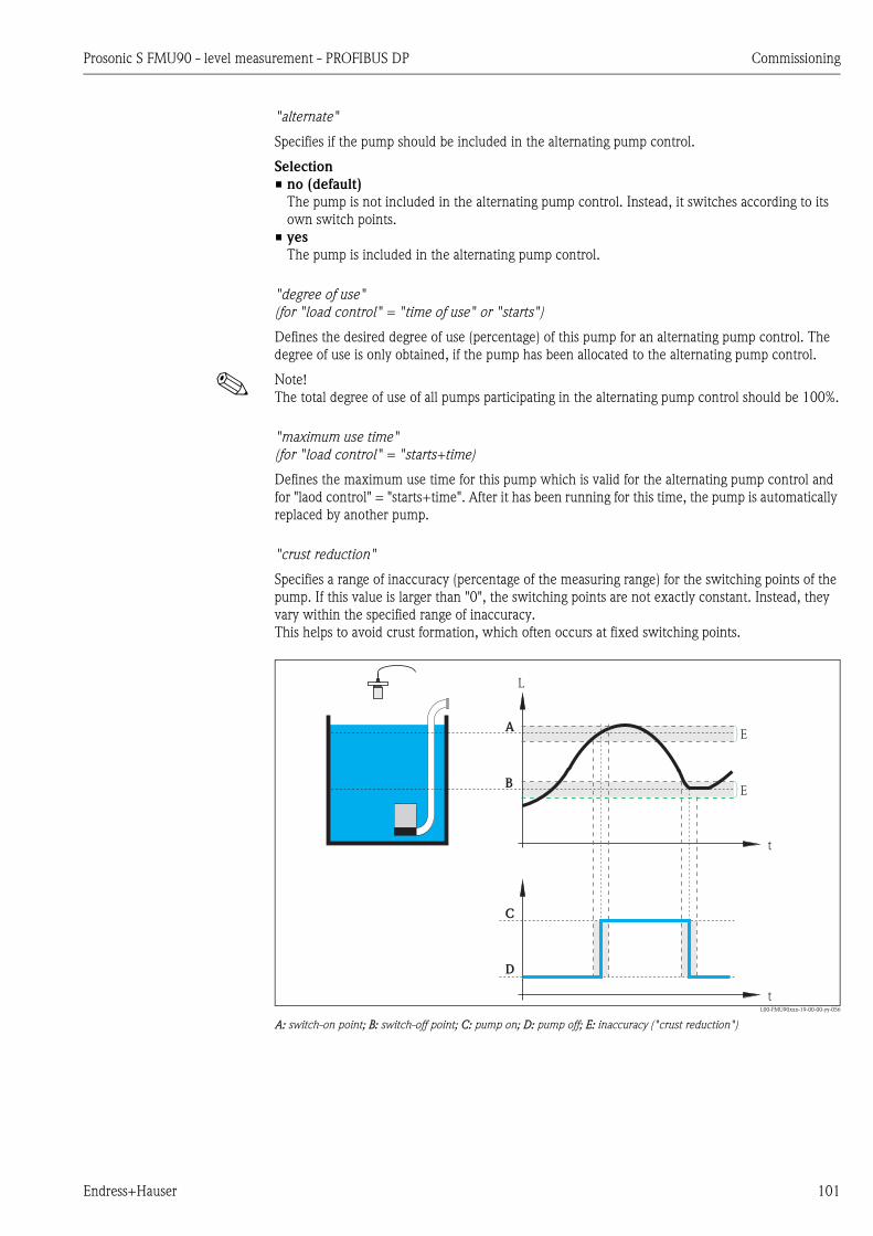
Prosonic S FMU90 - level measurement - PROFIBUS DP Commissioning
Endress+Hauser 101
"alternate"
Specifies if the pump should be included in the alternating pump control.
Selection
• no (default)
The pump is not included in the alternating pump control. Instead, it switches according to its
own switch points.
• yes
The pump is included in the alternating pump control.
"degree of use"
(for "load control" = "time of use" or "starts")
Defines the desired degree of use (percentage) of this pump for an alternating pump control. The
degree of use is only obtained, if the pump has been allocated to the alternating pump control.
! Note!
The total degree of use of all pumps participating in the alternating pump control should be 100%.
"maximum use time"
(for "load control" = "starts+time)
Defines the maximum use time for this pump which is valid for the alternating pump control and
for "laod control" = "starts+time". After it has been running for this time, the pump is automatically
replaced by another pump.
"crust reduction"
Specifies a range of inaccuracy (percentage of the measuring range) for the switching points of the
pump. If this value is larger than "0", the switching points are not exactly constant. Instead, they
vary within the specified range of inaccuracy.
This helps to avoid crust formation, which often occurs at fixed switching points.
L00-FMU90xxx-19-00-00-yy-056
A: switch-on point; B: switch-off point; C: pump on; D: pump off; E: inaccuracy ("crust reduction")
L
t
t
A
B
C
D
E
E

Commissioning Prosonic S FMU90 - level measurement - PROFIBUS DP
102 Endress+Hauser
"pump M/control N" (M = 1 - 6, N = 1 or 2)
(Part 2: Switching behavior for limit control)
"backlash interval" and "backlash time"
Use these parameters if you want to empty a vessel beyond the switch-off point in regular intervals.
The "backlash interval" determines after which time this extended pumping will occur.
The "backlash time" determines how long this additional pumping lasts.
L00-FMU90xxx-19-00-00-yy-057
A: switch-on point; B: switch-off point; C: pump on; D: pump off
E: backlash interval; F: backlash time
"error handling"
This parameter defines the reaction of the relay in the case of an error.
Selection:
• hold (default)
The current switching state of the relay is held.
• switch on
The relay is energized (i.e. the pump is switched on).
• switch off
The relay is de-energized (i.e. the pump is switched off).
• actual value
The relay switches according to the current measuring value (although its reliability is not
ensured).
pumpM/controlN RN304
backl. interval:
backlash time:
error handling:
t
t
L
A
B
C
D
E F
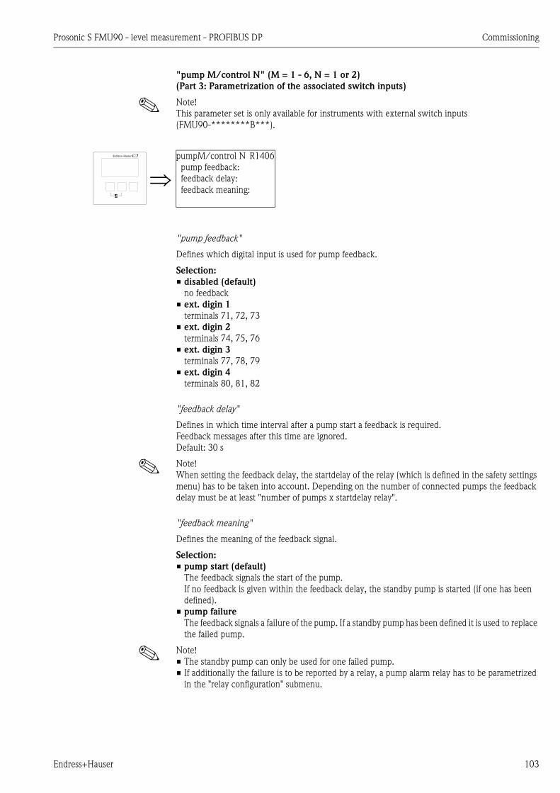
Prosonic S FMU90 - level measurement - PROFIBUS DP Commissioning
Endress+Hauser 103
"pump M/control N" (M = 1 - 6, N = 1 or 2)
(Part 3: Parametrization of the associated switch inputs)
! Note!
This parameter set is only available for instruments with external switch inputs
(FMU90-********B***).
"pump feedback"
Defines which digital input is used for pump feedback.
Selection:
• disabled (default)
no feedback
• ext. digin 1
terminals 71, 72, 73
• ext. digin 2
terminals 74, 75, 76
• ext. digin 3
terminals 77, 78, 79
• ext. digin 4
terminals 80, 81, 82
"feedback delay"
Defines in which time interval after a pump start a feedback is required.
Feedback messages after this time are ignored.
Default: 30 s
! Note!
When setting the feedback delay, the startdelay of the relay (which is defined in the safety settings
menu) has to be taken into account. Depending on the number of connected pumps the feedback
delay must be at least "number of pumps x startdelay relay".
"feedback meaning"
Defines the meaning of the feedback signal.
Selection:
• pump start (default)
The feedback signals the start of the pump.
If no feedback is given within the feedback delay, the standby pump is started (if one has been
defined).
• pump failure
The feedback signals a failure of the pump. If a standby pump has been defined it is used to replace
the failed pump.
! Note!
• The standby pump can only be used for one failed pump.
• If additionally the failure is to be reported by a relay, a pump alarm relay has to be parametrized
in the "relay configuration" submenu.
pumpM/control N R1406
pump feedback:
feedback delay:
feedback meaning:

Commissioning Prosonic S FMU90 - level measurement - PROFIBUS DP
104 Endress+Hauser
! Note!
Behaviour of the Prosonic S if a pump failure is reported bia the external switch inputs:
• If a pump failure is reported of a start report is missing during the operation of the pump, a pump
failure is indicated on the display and via an error code.
• The relay of the respective pump remains energized in order to report the pump failure. A reset
is only possible via "relay/controls/pump control N/basic setup/reset".
" Caution!
If the connected pumps are shut down as a consequence of an error message, it is advisable for
security reasons to switch off the control unit Prosonic S as well.
"relay allocation"
Allocates a relay to the pump.
Selection:
• All relays of the instrument version at hand
"relay N" (N = 1 - 6)
"function"
Allocates the desired function to the relay.
Selection:
• none (default)
• pump M/control N
! Note!
If a standby pump has been parametrized: The standby pump is always the last of the pumps.
Therefore, during the relay allocation the last pump must be selected in the "function" parameter.
Example:
number of pumps: 5
stand by pump: yes
=> for the standby pump: "function" = pump 5/control N
"invert"
Determines if the switching behavior of the relay is inverted.
Selection:
• no (default)
The switching behavior of the relay is not inverted. The relay is energized if the pump should be
switched on.
• yes
The switching behavior of the relay is inverted. The relay is energized if the pump should be
switched off.
relay allocation RN305
relay 1
relay 2
relay 3
relay 4
relay N RN306
function:
invert:

Prosonic S FMU90 - level measurement - PROFIBUS DP Commissioning
Endress+Hauser 105
"pump control N" (N = 1 or 2)
(Switching points for rate control)
"switch on point"
Specifies the switch-on point. Use the selected level unit.
" Caution!
After a change of the "unit level", the switch on point has to be checked and adjusted if required.
"switch off point"
Specifies the switch-off point. Use the selected level unit.
" Caution!
After a change of the "unit level", the switch off point has to be checked and adjusted if required.
"min pump rate"
Specifies the desired minimum pump rate (for details see section "limit control and rate control").
! Note!
If the vessel is to be emptied, a negative pump rate has to specified.
"crust reduction" subfunction
Specifies a range of inaccuracy (percentage of the measuring range) for the switching points. If this
value is larger then "0", the switching points are not exactly constant. Instead, they vary within the
specified range of inaccuracy.
This helps to avoid crust formation, which often occurs at fixed switching points.
L00-FMU90xxx-19-00-00-yy-056
A: switch-on point; B: switch-off point; C: pump onD: pump off; E: inaccuracy ("crust reduction")
pump control R13A3
switch on point:
switch off point:
min pump rate:
alternate:
L
t
t
A
B
C
D
E
E

Commissioning Prosonic S FMU90 - level measurement - PROFIBUS DP
106 Endress+Hauser
"switch on border"
Specifies the switch-on border for the rate control (for details see ä 82 "Limit control versus
pump rate control").
"hook up interval"
Specifies the time interval between the switching-on of the different pumps (for details see section
"limit control and rate control").
"alternate"
Determines if an alternating pump control is to be performed.
6.6.3 The "storm function" submenu
The storm function is used to avoid unnecessary running of the pump if the plant is flooded for a
short time (e.g. in the case of strong rainfall).
"storm function N" ( N = 1 or 2)
"storm function"
Use this parameter to switch the storm function on and off.
Selection:
• off (default)
• on
"switch on point"
Defines the switch on point for the storm function. If the level rises above this value, the storm
function becomes active, i.e. all pumps are switched off.
Default: 95%
! Note!
Storm detection is not indicated by an alarm.
"switch off point"
Defines the switch off point for the storm function. If the level falls below this value, the storm
function is deactivated, i.e. the normal pump control becomes valid again.
Default: 90%
! Note!
The switch off point must always be lower than the switch on point. It must be ensured that the
switch off point is reached without the pumps (e.g. by an outlet).
"storm time"
Defines the maximum duration of a storm.
If the storm function has been active for this time, it is automatically deactivated, even if the level
has not fallen below the switch off point or has risen above the switch on point a second time.
Default: 60 min
storm function 1 R13A3
storm function:
switch on point:
switch off point:
storm time:
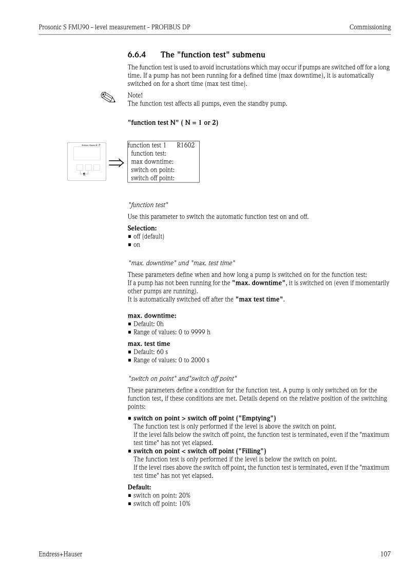
Prosonic S FMU90 - level measurement - PROFIBUS DP Commissioning
Endress+Hauser 107
6.6.4 The "function test" submenu
The function test is used to avoid incrustations which may occur if pumps are switched off for a long
time. If a pump has not been running for a defined time (max downtime), it is automatically
switched on for a short time (max test time).
! Note!
The function test affects all pumps, even the standby pump.
"function test N" ( N = 1 or 2)
"function test"
Use this parameter to switch the automatic function test on and off.
Selection:
• off (default)
• on
"max. downtime" und "max. test time"
These parameters define when and how long a pump is switched on for the function test:
If a pump has not been running for the "max. downtime", it is switched on (even if momentarily
other pumps are running).
It is automatically switched off after the "max test time".
max. downtime:
• Default: 0h
• Range of values: 0 to 9999 h
max. test time
• Default: 60 s
• Range of values: 0 to 2000 s
"switch on point" and"switch off point"
These parameters define a condition for the function test. A pump is only switched on for the
function test, if these conditions are met. Details depend on the relative position of the switching
points:
• switch on point > switch off point ("Emptying")
The function test is only performed if the level is above the switch on point.
If the level falls below the switch off point, the function test is terminated, even if the "maximum
test time" has not yet elapsed.
• switch on point < switch off point ("Filling")
The function test is only performed if the level is below the switch on point.
If the level rises above the switch off point, the function test is terminated, even if the "maximum
test time" has not yet elapsed.
Default:
• switch on point: 20%
• switch off point: 10%
function test 1 R1602
function test:
max downtime:
switch on point:
switch off point:

Commissioning Prosonic S FMU90 - level measurement - PROFIBUS DP
108 Endress+Hauser
6.6.5 The "flush control" submenu
The flush control is used to switch a pump on for a number of cycles (flush cycles) for a defined time
(flush time). This switching-on takes place within the defined number of pump cycles. The figure
below shows an example with 5 pump cycles and 2 flush cycles. The last two of the five pump cycles
are used for flushing.
A pump cycle always starts with the first pump being switched on and ends if all pumps are switched
off again.
L00-FMU90xxx-19-00-00-yy-109
A: 5 pump cycles; B: 2 flush cycles; C: flush delay; D: flush time
"flush control N" ( N = 1 or 2)
"flush control"
Use this parameter to switch the flush control on and off.
Selection:
• off (default)
• on
"pump cycles"
Defines the number of pump cycles after which the flush cycles are started.
Default: 0
"flush cycles"
Defines the number of flush cycles within the number of pump cycles.
Default: 0
! Note!
The number of flush cycles must be eqal or less than the number of pump cycles.
"flush time"
Defines, how long the flush relay is switched on.
Default: 0 s
Range of values: 0 to 255 s
"flush delay"
Defines the interval between the start of the pump cycle and the start of the flush relay.
Default: 0 s
Range of values: 0 to 255 s
t
1 32 4 5 1
C D
1 2
A
B
flush control 1 R1603
flush control:
pump cycles:
flush cycles:
flush time:

Prosonic S FMU90 - level measurement - PROFIBUS DP Commissioning
Endress+Hauser 109
"relay allocation"
Defines which relay is the flush relay.
Selection:
• All relays of the instrument version at hand.
"relay N" (N = 1 - 6)
"function"
Allocates the desired function to the relay.
Selection:
• none (default)
• flush control N
"invert"
Determines if the switching behavior of the relay is inverted.
Selection:
• no (default)
The switching behavior of the relay is not inverted. The relay is energized in the flush cycles.
• yes
The switching behavior of the relay is inverted. The relay is de-energized in the flush cycles.
relay allocation RX604
relay 1
relay 2
relay 3
relay 4
relay N RN605
function:
invert:
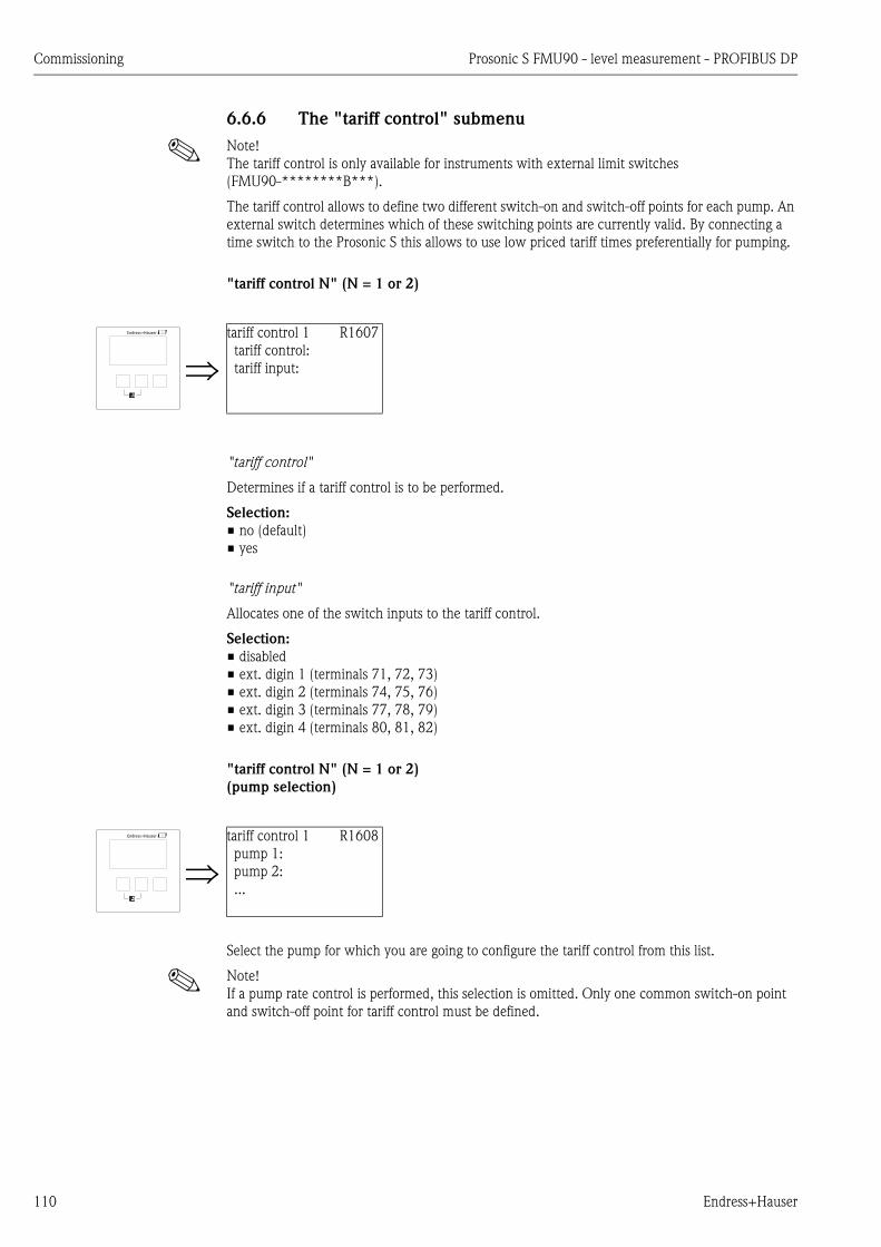
Commissioning Prosonic S FMU90 - level measurement - PROFIBUS DP
110 Endress+Hauser
6.6.6 The "tariff control" submenu
! Note!
The tariff control is only available for instruments with external limit switches
(FMU90-********B***).
The tariff control allows to define two different switch-on and switch-off points for each pump. An
external switch determines which of these switching points are currently valid. By connecting a
time switch to the Prosonic S this allows to use low priced tariff times preferentially for pumping.
"tariff control N" (N = 1 or 2)
"tariff control"
Determines if a tariff control is to be performed.
Selection:
• no (default)
• yes
"tariff input"
Allocates one of the switch inputs to the tariff control.
Selection:
• disabled
• ext. digin 1 (terminals 71, 72, 73)
• ext. digin 2 (terminals 74, 75, 76)
• ext. digin 3 (terminals 77, 78, 79)
• ext. digin 4 (terminals 80, 81, 82)
"tariff control N" (N = 1 or 2)
(pump selection)
Select the pump for which you are going to configure the tariff control from this list.
! Note!
If a pump rate control is performed, this selection is omitted. Only one common switch-on point
and switch-off point for tariff control must be defined.
tariff control 1 R1607
tariff control:
tariff input:
tariff control 1 R1608
pump 1:
pump 2:
...

Prosonic S FMU90 - level measurement - PROFIBUS DP Commissioning
Endress+Hauser 111
"tariff ctrl N pump M" (N = 1 or 2, M = 1 - 6)
"switch on point"
Displays the switch on point which is valid as long as no signal is present at the tariff switch input.
(Is equal to the switch-on point defined in the basic setup.)
"switch on point tariff"
Defines the switch of point which is valid if a signal is present at the tariff switch input.
"switch off point"
Displays the switch off point which is valid as long as no signal is present at the tariff switch input.
(Is equal to the switch-off point defined in the basic setup.)
"switch off point tariff
Defines the switch off point which is valid if a signal is present at the tariff switch input.
! Note!
By selecting appropriate tariff switch points preferential pumping during the low-price tariff times
can be achieved.
Example for emptying:
The switch points for tariff control are considerably below those of the basic setup. This results in a
preferred pumping and emptying of the vessel during the low-price tariff time. During the high price
tariff time on the other hand, as much water as possible is buffered in the vessel.
tariff ctr. 1 p1 R1608
switch on point:
switch on point:
switch off point:
switch off point:
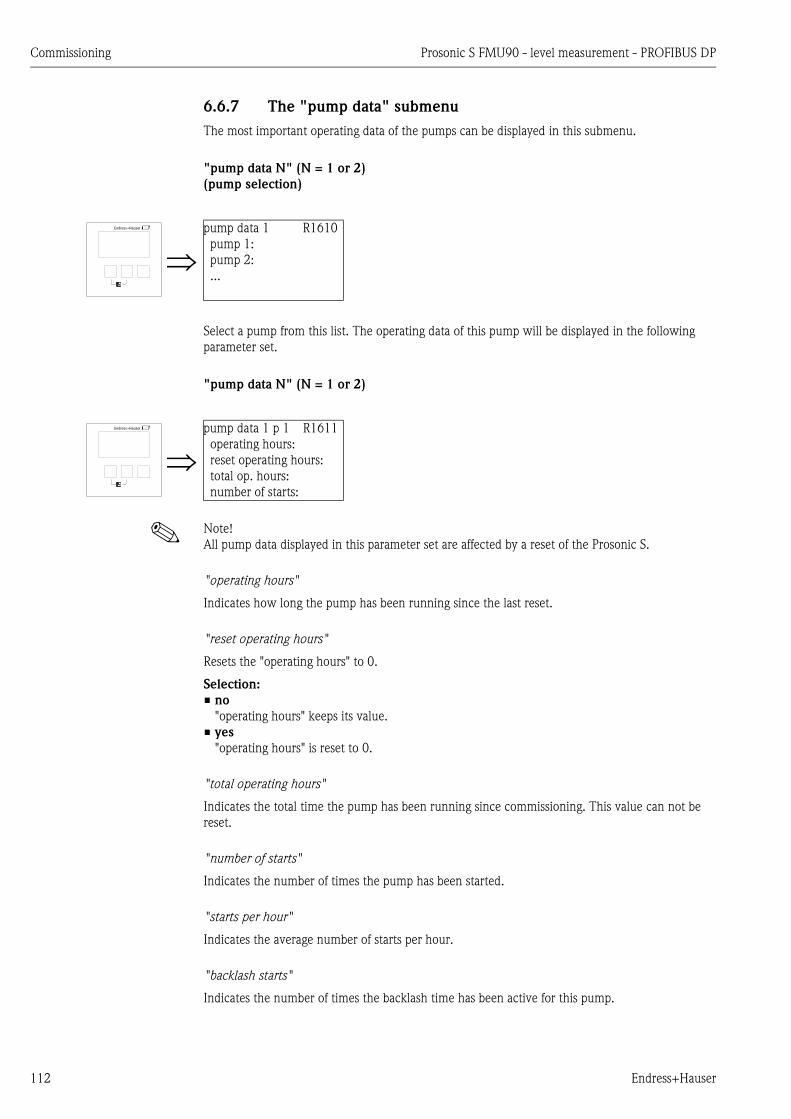
Commissioning Prosonic S FMU90 - level measurement - PROFIBUS DP
112 Endress+Hauser
6.6.7 The "pump data" submenu
The most important operating data of the pumps can be displayed in this submenu.
"pump data N" (N = 1 or 2)
(pump selection)
Select a pump from this list. The operating data of this pump will be displayed in the following
parameter set.
"pump data N" (N = 1 or 2)
! Note!
All pump data displayed in this parameter set are affected by a reset of the Prosonic S.
"operating hours"
Indicates how long the pump has been running since the last reset.
"reset operating hours"
Resets the "operating hours" to 0.
Selection:
• no
"operating hours" keeps its value.
• yes
"operating hours" is reset to 0.
"total operating hours"
Indicates the total time the pump has been running since commissioning. This value can not be
reset.
"number of starts"
Indicates the number of times the pump has been started.
"starts per hour"
Indicates the average number of starts per hour.
"backlash starts"
Indicates the number of times the backlash time has been active for this pump.
pump data 1 R1610
pump 1:
pump 2:
...
pump data 1 p 1 R1611
operating hours:
reset operating hours:
total op. hours:
number of starts:

Prosonic S FMU90 - level measurement - PROFIBUS DP Commissioning
Endress+Hauser 113
reset backlash starts
Resets the number of backlash starts to 0.
Selection:
• no
"backlash starts" keeps its value.
• yes
"backlash starts" is reset to 0.
last run time
Indicates how long the pump has been running since the last switch-on.
6.6.8 The "operating hours alarm" submenu
A maximum run time can be defined for each pump. The operating hours alarm becomes active as
soon as this run time is exceeded.
"operating hours alarm N" (N = 1 or 2)
"operating hours alarm"
Use this parameter to switch the operating hours control on and off.
Selection:
• off (default)
• on
"alarm delay"
Defines the delay for the operating hours alarm. This delay is the same for all pumps.
Default: 0s.
"operating hours alarm N" (N = 1 or 2)
(pump selection)
Select the pump for which you are going to configure the operating hours alarm.
op.hours alarm1 R1612
op.hours alarm:
alarm delay:
op.hours alarm 1 R1613
pump 1:
pump 2:
...
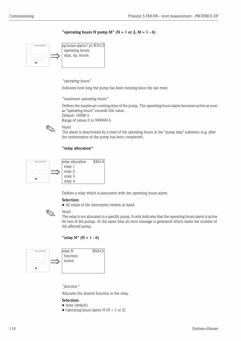
Commissioning Prosonic S FMU90 - level measurement - PROFIBUS DP
114 Endress+Hauser
"operating hours N pump M" (N = 1 or 2, M = 1 - 6)
"operating hours"
Indicates how long the pump has been running since the last reset.
"maximum operating hours"
Defines the maximum running time of the pump. The operating hours alarm becomes active as soon
as "operating hours" exceeds this value.
Default: 10000 h
Range of values 0 to 999999 h
! Note!
The alarm is deactivated by a reset of the operating hours in the "pump data" submenu (e.g. after
the maintenance of the pump has been completed).
"relay allocation"
Defines a relay which is associated with the operating hours alarm.
Selection:
• All relays of the instrument version at hand.
! Note!
The relay is not allocated to a specific pump. It only indicates that the operating hours alarm is active
for one of the pumps. At the same time an error message is generated which states the number of
the affected pump.
"relay N" (N = 1 - 6)
"function"
Allocates the desired function to the relay.
Selection:
• none (default)
• Operating hours alarm N (N = 1 or 2)
op.hours alarm1 p1 R1613
operating hours:
max. op. hours:
relay allocation RX614
relay 1
relay 2
relay 3
relay 4
relay N RN615
function:
invert:
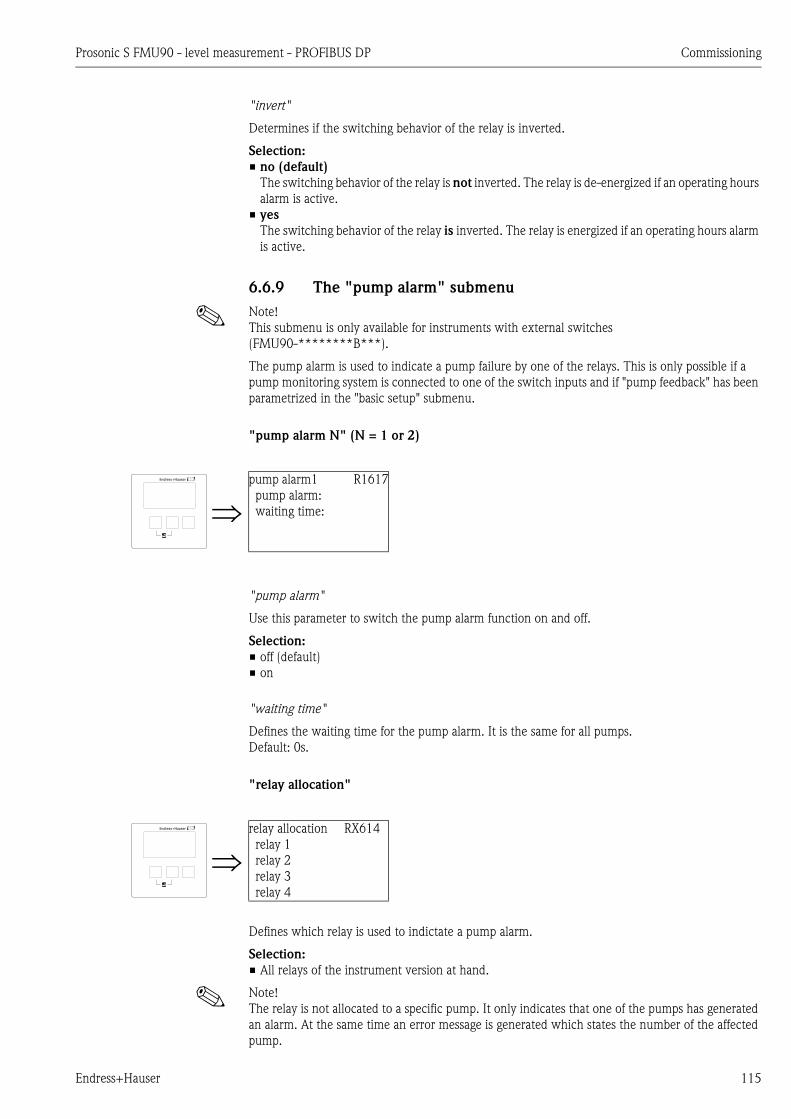
Prosonic S FMU90 - level measurement - PROFIBUS DP Commissioning
Endress+Hauser 115
"invert"
Determines if the switching behavior of the relay is inverted.
Selection:
• no (default)
The switching behavior of the relay is not inverted. The relay is de-energized if an operating hours
alarm is active.
• yes
The switching behavior of the relay is inverted. The relay is energized if an operating hours alarm
is active.
6.6.9 The "pump alarm" submenu
! Note!
This submenu is only available for instruments with external switches
(FMU90-********B***).
The pump alarm is used to indicate a pump failure by one of the relays. This is only possible if a
pump monitoring system is connected to one of the switch inputs and if "pump feedback" has been
parametrized in the "basic setup" submenu.
"pump alarm N" (N = 1 or 2)
"pump alarm"
Use this parameter to switch the pump alarm function on and off.
Selection:
• off (default)
• on
"waiting time"
Defines the waiting time for the pump alarm. It is the same for all pumps.
Default: 0s.
"relay allocation"
Defines which relay is used to indictate a pump alarm.
Selection:
• All relays of the instrument version at hand.
! Note!
The relay is not allocated to a specific pump. It only indicates that one of the pumps has generated
an alarm. At the same time an error message is generated which states the number of the affected
pump.
pump alarm1 R1617
pump alarm:
waiting time:
relay allocation RX614
relay 1
relay 2
relay 3
relay 4
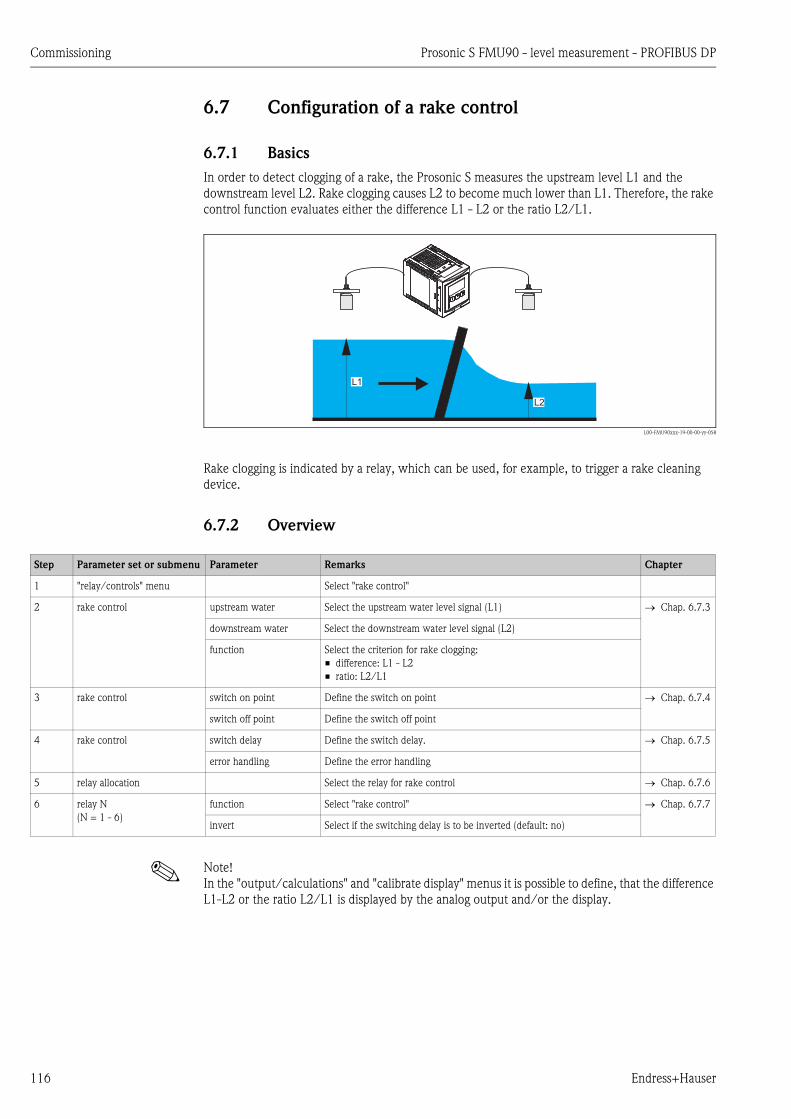
Commissioning Prosonic S FMU90 - level measurement - PROFIBUS DP
116 Endress+Hauser
6.7 Configuration of a rake control
6.7.1 Basics
In order to detect clogging of a rake, the Prosonic S measures the upstream level L1 and the
downstream level L2. Rake clogging causes L2 to become much lower than L1. Therefore, the rake
control function evaluates either the difference L1 - L2 or the ratio L2/L1.
L00-FMU90xxx-19-00-00-yy-058
Rake clogging is indicated by a relay, which can be used, for example, to trigger a rake cleaning
device.
6.7.2 Overview
! Note!
In the "output/calculations" and "calibrate display" menus it is possible to define, that the difference
L1-L2 or the ratio L2/L1 is displayed by the analog output and/or the display.
L1
L2
Step Parameter set or submenu Parameter Remarks Chapter
1 "relay/controls" menu Select "rake control"
2 rake control upstream water Select the upstream water level signal (L1) Chap. 6.7.3
downstream water Select the downstream water level signal (L2)
function Select the criterion for rake clogging:
• difference: L1 - L2
• ratio: L2/L1
3 rake control switch on point Define the switch on point Chap. 6.7.4
switch off point Define the switch off point
4 rake control switch delay Define the switch delay. Chap. 6.7.5
error handling Define the error handling
5 relay allocation Select the relay for rake control Chap. 6.7.6
6 relay N
(N = 1 - 6)
function Select "rake control" Chap. 6.7.7
invert Select if the switching delay is to be inverted (default: no)
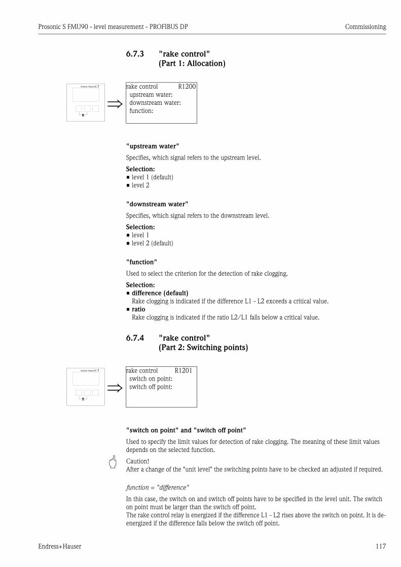
Prosonic S FMU90 - level measurement - PROFIBUS DP Commissioning
Endress+Hauser 117
6.7.3 "rake control"
(Part 1: Allocation)
"upstream water"
Specifies, which signal refers to the upstream level.
Selection:
• level 1 (default)
• level 2
"downstream water"
Specifies, which signal refers to the downstream level.
Selection:
• level 1
• level 2 (default)
"function"
Used to select the criterion for the detection of rake clogging.
Selection:
• difference (default)
Rake clogging is indicated if the difference L1 - L2 exceeds a critical value.
• ratio
Rake clogging is indicated if the ratio L2/L1 falls below a critical value.
6.7.4 "rake control"
(Part 2: Switching points)
"switch on point" and "switch off point"
Used to specify the limit values for detection of rake clogging. The meaning of these limit values
depends on the selected function.
" Caution!
After a change of the "unit level" the switching points have to be checked an adjusted if required.
function = "difference"
In this case, the switch on and switch off points have to be specified in the level unit. The switch
on point must be larger than the switch off point.
The rake control relay is energized if the difference L1 - L2 rises above the switch on point. It is de-
energized if the difference falls below the switch off point.
rake control R1200
upstream water:
downstream water:
function:
rake control R1201
switch on point:
switch off point:

Commissioning Prosonic S FMU90 - level measurement - PROFIBUS DP
118 Endress+Hauser
L00-FMU90xxx-19-00-00-yy-059
A: switch on point; B: switch off point;
C: relay energized (i.e. rake cleaning on); D: relay de-energized (i.e. rake cleaning off)
C
D
t
t
L1
L2
L1 - L2
A
B

Prosonic S FMU90 - level measurement - PROFIBUS DP Commissioning
Endress+Hauser 119
function = "ratio"
In this case, the switch on and switch off points are numbers between 0 and 1. The switch on point
must be smaller than the switch off point.
The rake control relay is energized if the ratio L2/L1 falls below the switch on point. It is de-
energized if the ratio rises above the switch off point.
L00-FMU90xxx-19-00-00-yy-060
A: switch on point; B: switch off point;
C: relay energized (i.e. rake cleaning on); D: relay de-energized (i.e. rake cleaning off)
6.7.5 "rake control"
(Part 3: Switching parameters)
"switch delay"
Specifies the switch delay for the rake control.
The relay does not switch immediately after the switch on point has been exceeded but only after
the specified switch delay. This is to prevent that random fluctuations of L1 or L2 activate the rake
cleaning unnecessarily.
"error handling"
Specifies the behavior of the rake control relay in case of an error.
t
t
L2/L1
L1
L2
A
B
C
D
rake control R1202
switch delay:
error handling:
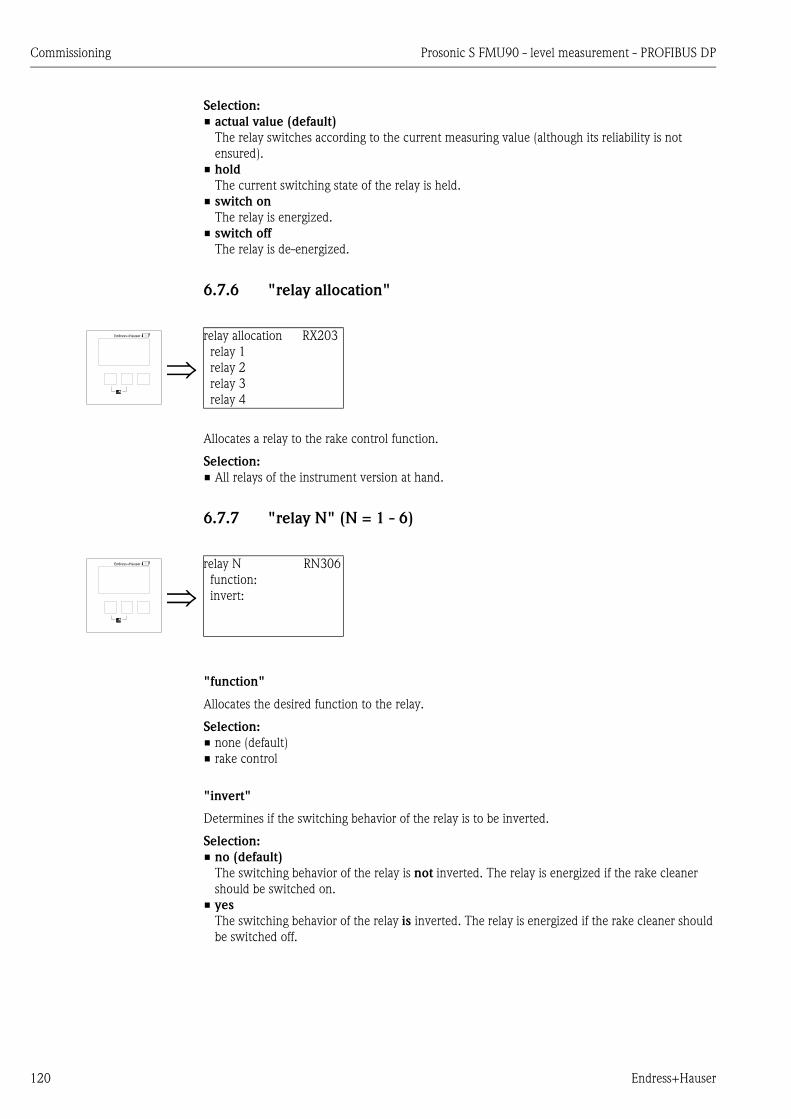
Commissioning Prosonic S FMU90 - level measurement - PROFIBUS DP
120 Endress+Hauser
Selection:
• actual value (default)
The relay switches according to the current measuring value (although its reliability is not
ensured).
• hold
The current switching state of the relay is held.
• switch on
The relay is energized.
• switch off
The relay is de-energized.
6.7.6 "relay allocation"
Allocates a relay to the rake control function.
Selection:
• All relays of the instrument version at hand.
6.7.7 "relay N" (N = 1 - 6)
"function"
Allocates the desired function to the relay.
Selection:
• none (default)
• rake control
"invert"
Determines if the switching behavior of the relay is to be inverted.
Selection:
• no (default)
The switching behavior of the relay is not inverted. The relay is energized if the rake cleaner
should be switched on.
• yes
The switching behavior of the relay is inverted. The relay is energized if the rake cleaner should
be switched off.
relay allocation RX203
relay 1
relay 2
relay 3
relay 4
relay N RN306
function:
invert:
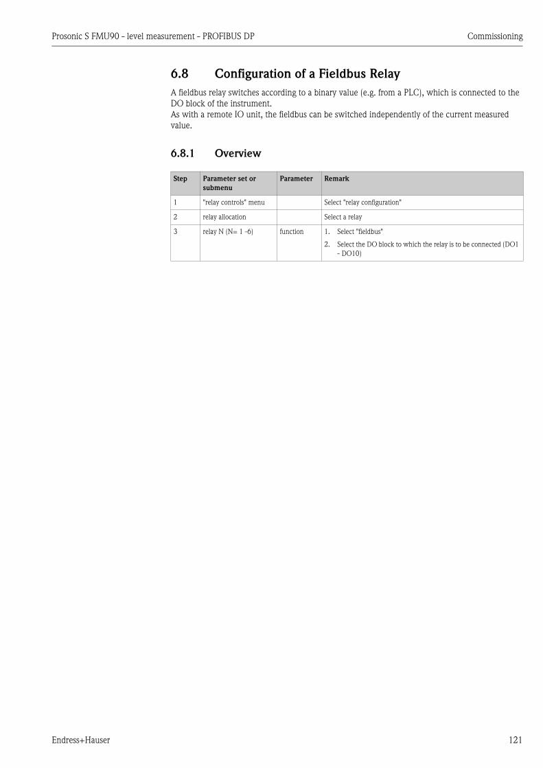
Prosonic S FMU90 - level measurement - PROFIBUS DP Commissioning
Endress+Hauser 121
6.8 Configuration of a Fieldbus Relay
A fieldbus relay switches according to a binary value (e.g. from a PLC), which is connected to the
DO block of the instrument.
As with a remote IO unit, the fieldbus can be switched independently of the current measured
value.
6.8.1 Overview
Step Parameter set or
submenu
Parameter Remark
1 "relay controls" menu Select "relay configuration"
2 relay allocation Select a relay
3 relay N (N= 1 -6) function 1. Select "fieldbus"
2. Select the DO block to which the relay is to be connected (DO1
- DO10)
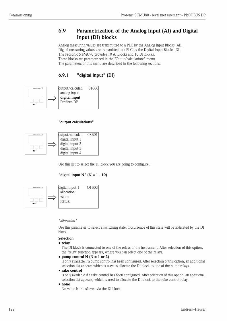
Commissioning Prosonic S FMU90 - level measurement - PROFIBUS DP
122 Endress+Hauser
6.9 Parametrization of the Analog Input (AI) and Digital
Input (DI) blocks
Analog measuring values are transmitted to a PLC by the Analog Input Blocks (AI).
Digital measuring values are transmitted to a PLC by the Digital Input Blocks (DI).
The Prosonic S FMU90 provides 10 AI Blocks and 10 DI Blocks.
These blocks are parametrized in the "Outut/calculations" menu.
The parameters of this menu are described in the following sections.
6.9.1 "digital input" (DI)
"output calculations"
Use this list to select the DI block you are going to configure.
"digital input N" (N = 1 - 10)
"allocation"
Use this parameter to select a switching state. Occurrence of this state will be indicated by the DI
block.
Selection
• relay
The DI block is connected to one of the relays of the instrument. After selection of this option,
the "relay" function appears, where you can select one of the relays.
• pump control N (N = 1 or 2)
is only available if a pump control has been configured. After selection of this option, an additional
selection list appears which is used to allocate the DI block to one of the pump relays.
• rake control
is only available if a rake control has been configured. After selection of this option, an additional
selection list appears, which is used to allocate the DI block to the rake control relay.
• none
No value is transferred via the DI block.
output/calculat. 01000
analog input
digital input
Profibus DP
output/calculat. 0XB01
digital input 1
digital input 2
digital input 3
digital input 4
digital input 1 O1B03
allocation:
value:
status:
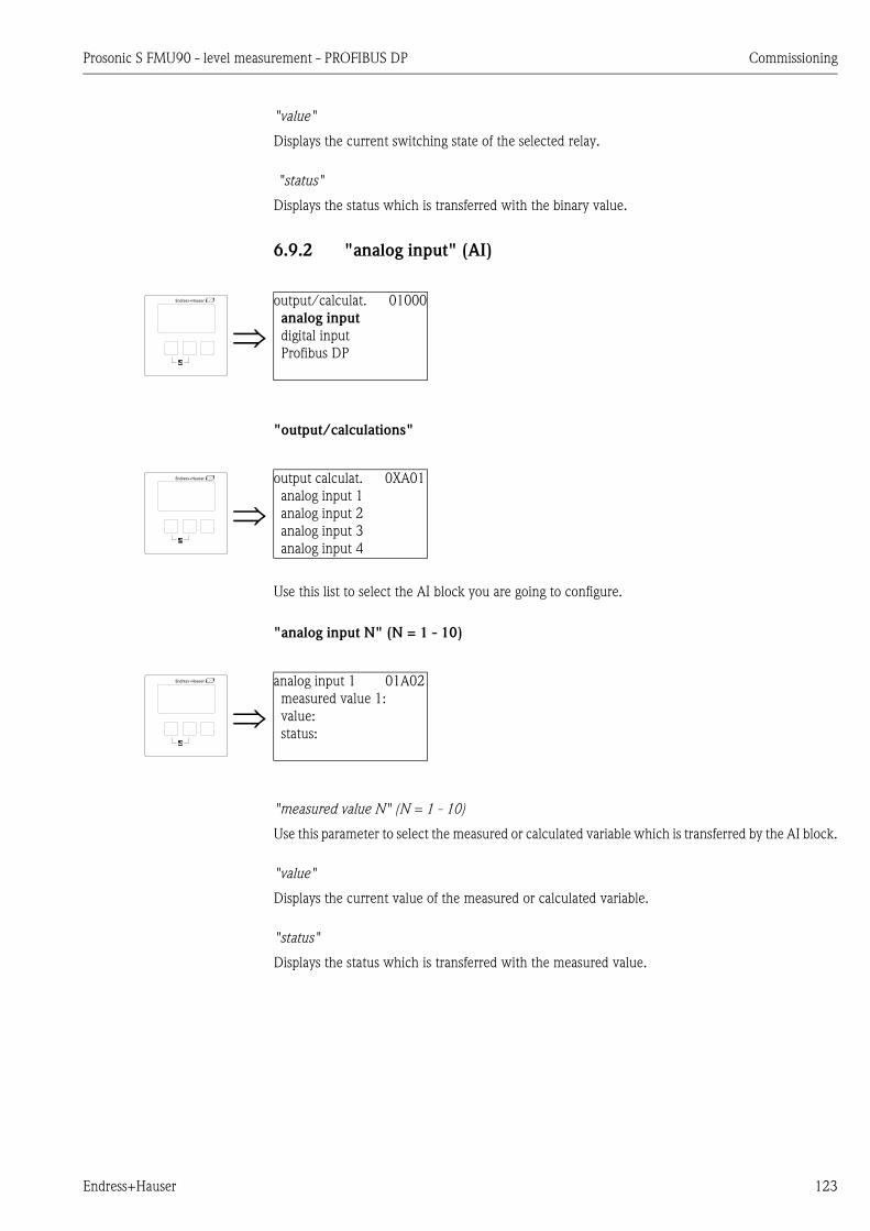
Prosonic S FMU90 - level measurement - PROFIBUS DP Commissioning
Endress+Hauser 123
"value"
Displays the current switching state of the selected relay.
"status"
Displays the status which is transferred with the binary value.
6.9.2 "analog input" (AI)
"output/calculations"
Use this list to select the AI block you are going to configure.
"analog input N" (N = 1 - 10)
"measured value N" (N = 1 - 10)
Use this parameter to select the measured or calculated variable which is transferred by the AI block.
"value"
Displays the current value of the measured or calculated variable.
"status"
Displays the status which is transferred with the measured value.
output/calculat. 01000
analog input
digital input
Profibus DP
output calculat. 0XA01
analog input 1
analog input 2
analog input 3
analog input 4
analog input 1 01A02
measured value 1:
value:
status:

Commissioning Prosonic S FMU90 - level measurement - PROFIBUS DP
124 Endress+Hauser
6.10 Parametrization of the cyclic data telegram
! Note!
• Basic information on the cyclic data exchange between the measuring instrument and an
automation system (e.g. PLC) are described in Operating Instructions BA00034S, "PROFIBUS
DP/PA - Guidelines for planning and commissioning"
• Cyclic data exchange is only possible if the appropriate device database files (GSD) have been
uploaded to the automation system. For details refer to Chap. 6.1.3.
6.10.1 Data format
Analog values
With PROFIBUS DP the cyclic data transfer of analog values to the PLC uses data blocks (modules)
of 5 bytes each. The measured value is reperesented in the first four bytes as a floating point number
according to the IEEE standard. The fifth byte contains a standardized information about the
instrument status. For details refer to BA00034S.
Digital values
With PROFIBUS DP the cyclic data transfer of digital values uses blocks (modules) of 2 bytes each.
The first byte contains the digital value. The second byte contains the associated status information.
For details refer to BA00034S.
6.10.2 Modules for the cyclic data telegram
Analog values (AI)
Every AI block of the Prosonic S FMU90 provides a five byte module for the cyclic data telegram
(from the instrument to the PLC). According to the PROFIBUS specifications "Profile for Process
Control Devices" there are two options for each of these modules:
• AI (OUT): The module in transmitted in the cyclic data telegram.
• Free Place: The module is not part of the cyclic data telegram.
The option is selected in the configuration tool of the respective PLC. For details refer to the
Operating Instructions of the manufacturer-specific configuration tool.
Digital values (DI)
Every DI block of the Prosonic S FMU90 provides a two byte module for the cyclic data telegram
(from the instrument to the PLC). According to the PROFIBUS specifications "Profile for Process
Control Devices" there are two options for each of these modules:
• AI(OUT): The module in transmitted in the cyclic data telegram.
• Free Place: The module is not part of the cyclic data telegram.
The option is selected in the configuration tool of the respective PLC. For details refer to the
Operating Instructions of the manufacturer-specific configuration tool.
Digital values (DO)
Every DO block of the Prosonic S provides a two byte module for the cyclic data telegram (from the
PLC to the instrument). According to the PROFIBUS specifications "Profile for Process Control
Devices" there are the following options for each of these modules:
• DO (SP_D)
• DO (SP_D/CB_D)
• DO (RCAS_IN_D/RCAS_OUT_D)
• DO (RCAS_IN-D/RCAS_OUT_D/CB_D)
• Free Place

Prosonic S FMU90 - level measurement - PROFIBUS DP Commissioning
Endress+Hauser 125
The option is selected in the configuration tool of the respective PLC. For details refer to the
Operating Instructions of the manufacturer-specific configuration tool.
6.10.3 Default configuration of the cyclic data telegram
1 channel version (FMU90 - *****1***)
For the one channel version, the AI blocks 1 to 3 are contained in the data telegram and transfer
level, distance and temperature. All other AI blocks (AI4 to AI10) are not used by default.
! Note!
By default no digital values (DI/DO) are contained in the cyclic data telegram.
2 cahnnel version (FMU90 - *****2***)
AI blocks 1 to 6 are contained in the cyclic data telegram and transfer level, distance and
temperature of the two sensors. All other AI blocks (AI7 to AI10) are not used by default.
! Note!
By default no digital values (DI/DO) are contained in the cyclic data telegram.
Byte Block Access type Format Measured value1)
1) This measured value allocation can be changed in "outout/calculations/analog input/analog input N/measured
value N" (N = 1 to 20).
Unit2)
2) The unit can be changed in
"level/level N/basic setup/unit level"
"device properties/operating parameters/distance unit"
"device properties/operating parameters/temperature unit"
0, 1, 2, 3 AI 1 read IEEE754 level 1 m
4 Status byte Status level 1 -
5, 6, 7, 8 AI 2 read IEEE754 distance 1 m
9 Status byte Status distance 1 -
10, 11, 12, 13 AI 3 read IEEE754 temperature 1 °C
14 Status byte Status temperature 1 -
Byte Block Access type Format Measured value1)
1) This measured value allocation can be changed in "outout/calculations/analog input/analog input N/measured
value N" (N = 1 to 20).
Unit2)
2) The unit can be changed in "level/level N/basic setup/unit level".
0, 1, 2, 3 AI 1 read IEEE754 level 1 m
4 Status byte Status level 1 -
5, 6, 7, 8 AI 2 read IEEE754 level 2 m
9 Status byte Status level 2 -
10, 11, 12, 13 AI 3 read IEEE754 distance 1 m
14 Status byte Status distance 1 -
15, 16, 17, 18 AI 4 read IEEE754 distance 2 m
19 Status byte Status distance 2 -
20, 21, 22, 23 AI 5 read IEEE754 temperature 1 m
24 Status byte Status temperature 1 -
25, 26, 27, 28 AI 6 read IEEE754 temperature 2 m
29 Status byte Status temperature 2 -
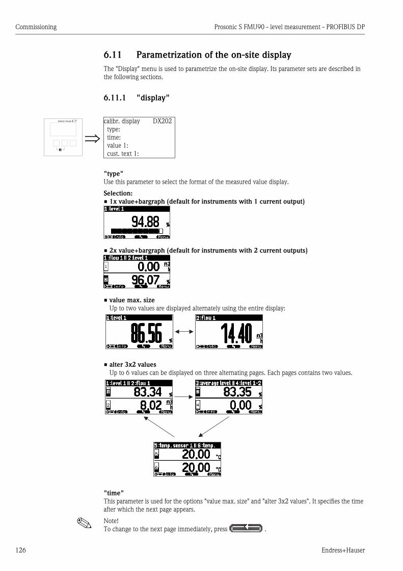
Commissioning Prosonic S FMU90 - level measurement - PROFIBUS DP
126 Endress+Hauser
6.11 Parametrization of the on-site display
The "Display" menu is used to parametrize the on-site display. Its parameter sets are described in
the following sections.
6.11.1 "display"
"type"
Use this parameter to select the format of the measured value display.
Selection:
• 1x value+bargraph (default for instruments with 1 current output)
• 2x value+bargraph (default for instruments with 2 current outputs)
• value max. size
Up to two values are displayed alternately using the entire display:
• alter 3x2 values
Up to 6 values can be displayed on three alternating pages. Each pages contains two values.
"time"
This parameter is used for the options "value max. size" and "alter 3x2 values". It specifies the time
after which the next page appears.
! Note!
To change to the next page immediately, press .
calibr. display DX202
type:
time:
value 1:
cust. text 1:
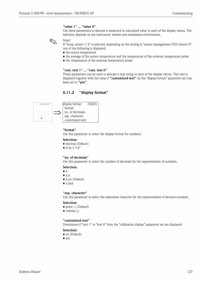
Prosonic S FMU90 - level measurement - PROFIBUS DP Commissioning
Endress+Hauser 127
"value 1" ... "value 6"
Use these parameters to allocate a measured or calculated value to each of the display values. The
selection depends on the instrument version and installation environment.
! Note!
If "temp. sensor 1/2" is selected, depending on the setting in "sensor management/FDU sensor N"
one of the following is displayed:
• the sensor temperature
• the average of the sensor temperature and the temperature of the external temperature probe
• the temperature of the external temperature probe
"cust. text 1" ... "cust. text 6"
These parameters can be used to allocate a text string to each of the display values. This text is
displayed together with the value if "customized text" (in the "display format" parameter set) has
been set to "yes".
6.11.2 "display format"
"format"
Use this parameter to select the display format for numbers.
Selection:
• decimal (Default)
• ft-in-1/16"
"no. of decimals"
Use this parameter to select the number of decimals for the representation of numbers.
Selection:
• x
• x.x
• x.xx (Default)
• x.xxx
"sep. character"
Use this parameter to select the separation character for the representation of decimal numbers.
Selection:
• point (.) (Default)
• comma (,)
"customized text"
Determines if "text 1" to "text 6" from the "calibration display" parameter set are displayed.
Selection:
• no (Default)
• yes
display format DX201
format:
no. of decimals:
sep. character:
customized text:
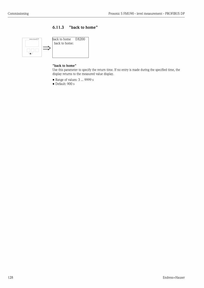
Commissioning Prosonic S FMU90 - level measurement - PROFIBUS DP
128 Endress+Hauser
6.11.3 "back to home"
"back to home"
Use this parameter to specify the return time. If no entry is made during the specified time, the
display returns to the measured value display.
• Range of values: 3 ... 9999 s
• Default: 900 s
back to home DX200
back to home:

Prosonic S FMU90 - level measurement - PROFIBUS DP Troubleshooting
Endress+Hauser 129
7 Troubleshooting
7.1 System error messages
7.1.1 Error signal
Errors occurring during commissioning or operation are signalled in the following way:
• Error symbol, error code and error description on the display and operating module
• Status of the output values in the cyclic data telegram
• In the menu: "system information/error list/actual error"
7.1.2 Last error
To access a list of the last errors which have been cleared, go to "system information/error list/last
error".
7.1.3 Types of errors
Type of error Display symbol Meaning
Alarm (A)
continuous
The output signal assumes a value which can be defi-
ned by the "output on alarm" function:
• MAX: 110%, 22 mA
• MIN: -10%, 3,6 mA
• Hold: last value is held
• user-specific value
An error message appears on the display.
The operating state LED lights red
The status of the output signal of the affected blocks is
BAD.
Warning (W)
flashing
The instrument continues to measure.
An error message appears on the display.
The operating state LED flashes red.
The status of the output signal of the affected blocks is
UNCERTAIN.
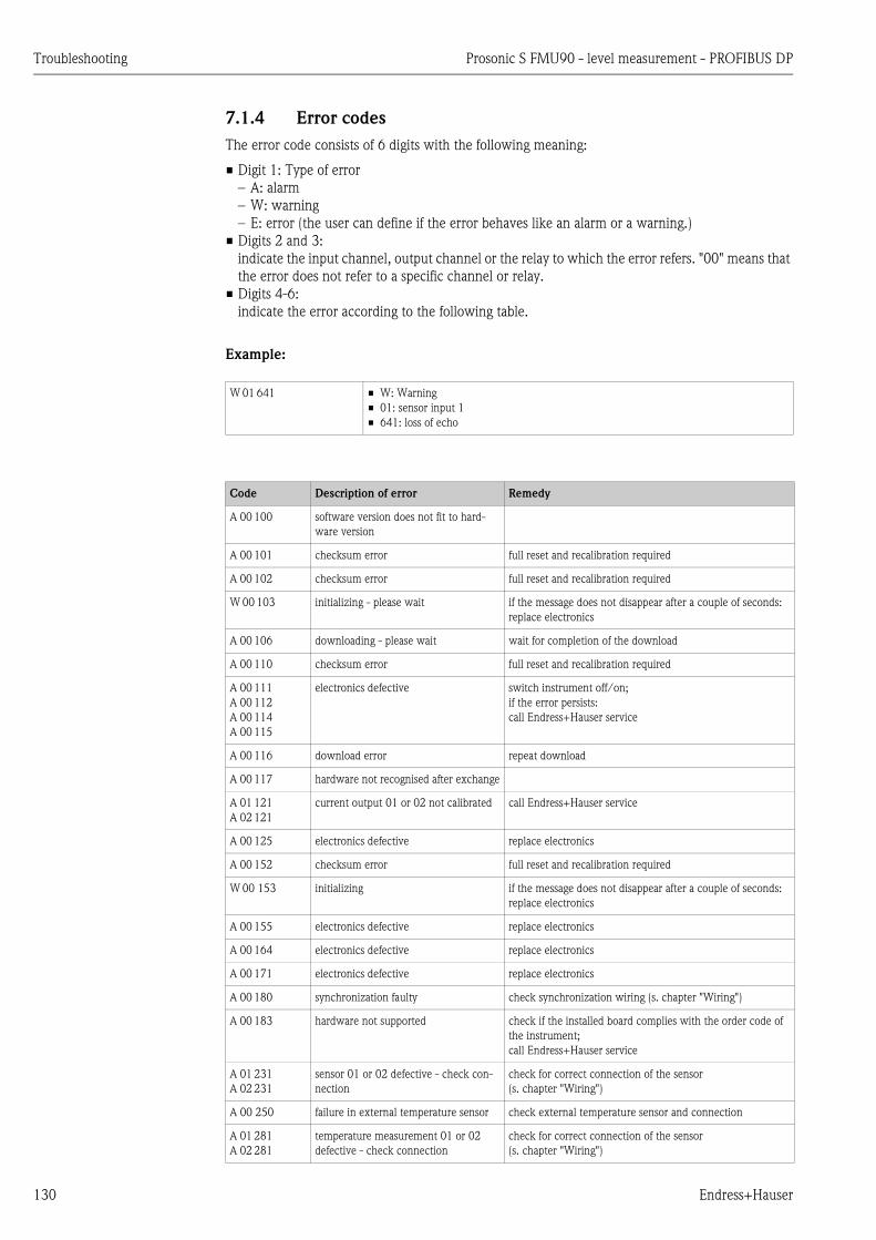
Troubleshooting Prosonic S FMU90 - level measurement - PROFIBUS DP
130 Endress+Hauser
7.1.4 Error codes
The error code consists of 6 digits with the following meaning:
• Digit 1: Type of error
– A: alarm
– W: warning
– E: error (the user can define if the error behaves like an alarm or a warning.)
• Digits 2 and 3:
indicate the input channel, output channel or the relay to which the error refers. "00" means that
the error does not refer to a specific channel or relay.
• Digits 4-6:
indicate the error according to the following table.
Example:
W 01 641 • W: Warning
• 01: sensor input 1
• 641: loss of echo
Code Description of error Remedy
A 00 100 software version does not fit to hard-
ware version
A 00 101 checksum error full reset and recalibration required
A 00 102 checksum error full reset and recalibration required
W 00 103 initializing - please wait if the message does not disappear after a couple of seconds:
replace electronics
A 00 106 downloading - please wait wait for completion of the download
A 00 110 checksum error full reset and recalibration required
A 00 111
A 00 112
A 00 114
A 00 115
electronics defective switch instrument off/on;
if the error persists:
call Endress+Hauser service
A 00 116 download error repeat download
A 00 117 hardware not recognised after exchange
A 01 121
A 02 121
current output 01 or 02 not calibrated call Endress+Hauser service
A 00 125 electronics defective replace electronics
A 00 152 checksum error full reset and recalibration required
W 00 153 initializing if the message does not disappear after a couple of seconds:
replace electronics
A 00 155 electronics defective replace electronics
A 00 164 electronics defective replace electronics
A 00 171 electronics defective replace electronics
A 00 180 synchronization faulty check synchronization wiring (s. chapter "Wiring")
A 00 183 hardware not supported check if the installed board complies with the order code of
the instrument;
call Endress+Hauser service
A 01 231
A 02 231
sensor 01 or 02 defective - check con-
nection
check for correct connection of the sensor
(s. chapter "Wiring")
A 00 250 failure in external temperature sensor check external temperature sensor and connection
A 01 281
A 02 281
temperature measurement 01 or 02
defective - check connection
check for correct connection of the sensor
(s. chapter "Wiring")
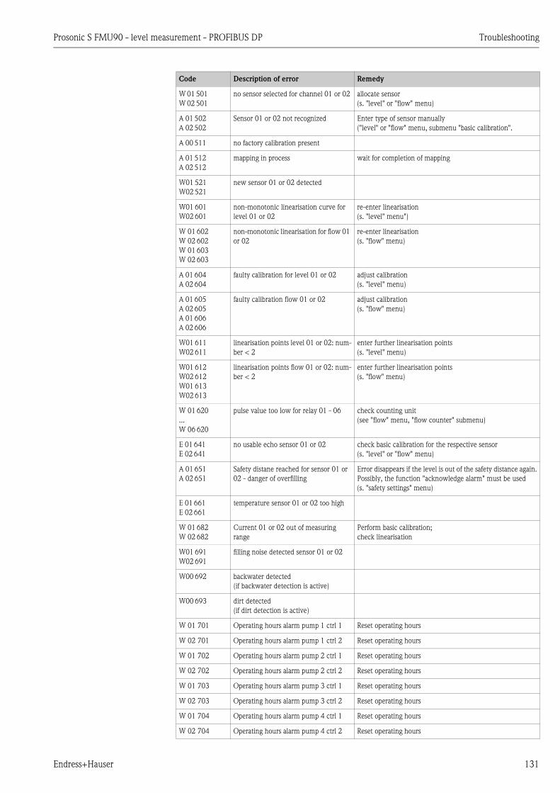
Prosonic S FMU90 - level measurement - PROFIBUS DP Troubleshooting
Endress+Hauser 131
W 01 501
W 02 501
no sensor selected for channel 01 or 02 allocate sensor
(s. "level" or "flow" menu)
A 01 502
A 02 502
Sensor 01 or 02 not recognized Enter type of sensor manually
("level" or "flow" menu, submenu "basic calibration".
A 00 511 no factory calibration present
A 01 512
A 02 512
mapping in process wait for completion of mapping
W01 521
W02 521
new sensor 01 or 02 detected
W01 601
W02 601
non-monotonic linearisation curve for
level 01 or 02
re-enter linearisation
(s. "level" menu")
W 01 602
W 02 602
W 01 603
W 02 603
non-monotonic linearisation for flow 01
or 02
re-enter linearisation
(s. "flow" menu)
A 01 604
A 02 604
faulty calibration for level 01 or 02 adjust calibration
(s. "level" menu)
A 01 605
A 02 605
A 01 606
A 02 606
faulty calibration flow 01 or 02 adjust calibration
(s. "flow" menu)
W01 611
W02 611
linearisation points level 01 or 02: num-
ber < 2
enter further linearisation points
(s. "level" menu)
W01 612
W02 612
W01 613
W02 613
linearisation points flow 01 or 02: num-
ber < 2
enter further linearisation points
(s. "flow" menu)
W 01 620
...
W 06 620
pulse value too low for relay 01 - 06 check counting unit
(see "flow" menu, "flow counter" submenu)
E 01 641
E 02 641
no usable echo sensor 01 or 02 check basic calibration for the respective sensor
(s. "level" or "flow" menu)
A 01 651
A 02 651
Safety distane reached for sensor 01 or
02 - danger of overfilling
Error disappears if the level is out of the safety distance again.
Possibly, the function "acknowledge alarm" must be used
(s. "safety settings" menu)
E 01 661
E 02 661
temperature sensor 01 or 02 too high
W 01 682
W 02 682
Current 01 or 02 out of measuring
range
Perform basic calibration;
check linearisation
W01 691
W02 691
filling noise detected sensor 01 or 02
W00 692 backwater detected
(if backwater detection is active)
W00 693 dirt detected
(if dirt detection is active)
W 01 701 Operating hours alarm pump 1 ctrl 1 Reset operating hours
W 02 701 Operating hours alarm pump 1 ctrl 2 Reset operating hours
W 01 702 Operating hours alarm pump 2 ctrl 1 Reset operating hours
W 02 702 Operating hours alarm pump 2 ctrl 2 Reset operating hours
W 01 703 Operating hours alarm pump 3 ctrl 1 Reset operating hours
W 02 703 Operating hours alarm pump 3 ctrl 2 Reset operating hours
W 01 704 Operating hours alarm pump 4 ctrl 1 Reset operating hours
W 02 704 Operating hours alarm pump 4 ctrl 2 Reset operating hours
Code Description of error Remedy

Troubleshooting Prosonic S FMU90 - level measurement - PROFIBUS DP
132 Endress+Hauser
W 01 705 Operating hours alarm pump 5 ctrl 1 Reset operating hours
W 02 705 Operating hours alarm pump 5 ctrl 2 Reset operating hours
W 01 706 Operating hours alarm pump 6 ctrl 1 Reset operating hours
W 02 706 Operating hours alarm pump 6 ctrl 2 Reset operating hours
W 01 711 Failure of pump 1 ctrl 1 check pump1)
W 02 711 Failure of pump 1 ctrl 2 check pump
W 01 712 Failure of pump 2 ctrl 1 check pump
W 02 712 Failure of pump 2 ctrl 2 check pump
W 01 713 Failure of pump 3 ctrl 1 check pump
W 02 713 Failure of pump 3 ctrl 2 check pump
W 01 714 Failure of pump 4 ctrl 1 check pump
W 02 714 Failure of pump 4 ctrl 2 check pump
W 01 715 Failure of pump 5 ctrl 1 check pump
W 02 715 Failure of pump 5 ctrl 2 check pump
W 01 716 Failure of pump 6 ctrl 1 check pump
W 02 716 Failure of pump 6 ctrl 2 check pump
W00 801 simulation level swichted on switch off level simulation
(s. "level" menu)
W01 802
W02 802
simulation sensor 01 or 02 switched on switch off simulation
W01 803
W02 803
W01 804
W02 804
simulation flow switched on switch off simulation
(see "flow" menu)
W01 805 simulation current 01 switched on switch off simulation
(s. "output/calculations" menu)
W02 806 simulation current 02 switched on switch off simulation
(see "output/calculations" menu)
W01 807
...
W06 807
simulation relay 01 - 06 switched on switch off simulation
W01 808
W02 808
sensor 01 or 02 switched off switch on sensor
(see "device properties/sensor management" menu)
W01 809
W02 809
current calibration D/A active
A 00 820
...
A 00 832
Different units for calculation of average
value, sum, difference or rake control
Check the units of the respective basic calibrations
(s. "level" or "flow" menu)
1) After a repair of the pump the pump control must be reset ( Chap. 6.2.3) or the FMU90 must be switched off and
on.
Code Description of error Remedy

Prosonic S FMU90 - level measurement - PROFIBUS DP Troubleshooting
Endress+Hauser 133
7.1.5 Influence of the errors on the status byte of the output signal
The following table specifies the status, which the block output values assume if an error is present.
There are three possible status values: GOOD, UNCERTAIN and BAD.
The status is transmitted to the next block. If different status values occur in one chain, the weaker
status is overwritten by the stronger one according to the following priority:
• BAD overwrites UNCERTAIN and GOOD.
• UNCERTAIN overwrites GOOD.
• GOOD overwrites no other status.
Therefore, the strongest status of the chain remains at the output of the AI Block. This status is
transferred to the PLC together with the measured value.
Examples
! Note!
Errors may occur at different places within the instrument. Each error is allocated to one of the
following areas:
• sensor error => sensor block (US 1 - US 10)
• level error => level block (LE 1 - LE 10)
• calculation error => sum block/averaging block (SL 1 - SL 10; AL 1 - AL 10)
• output error => AI Block (AI 1 - AI 20)
Each sensor block (US1 to US10) has two outputs. The first transmits for the measured distance D,
the second transmits the sensor temperature T.
L00-FMU95xxx-19-00-00-yy-006
A: UNCERTAIN from the sensor block (US1) overwrites GOOD from the level block (LE1);
B: BAD from the level block (LE1) overwrites UNCERTAIN from the sensor block (US1);
C: BAD from the second level block (LE2) overwrites GOOD from the first level block (LE1). Therefore, the status at the
output of the averaging block AL1 is BAD.
US1 LE1 AI1
W 01 661
GOOD
UNCERTAIN UNCERTAIN UNCERTAIN
FDU9x
LE1 AI1
W 01 661
W 01 601BAD
UNCERTAIN BAD BAD
LE1
GOOD
GOOD
GOOD GOOD
LE2
W 01 601BAD
GOOD BAD
AL1BAD
AI1BAD
A
B
C
FDU9xFDU9x
US1LE1 AI1D
T
AI1UNCERTAIN
AI2
GOOD
US1US1
D
T
US1US1
D
T
FDU9x
FDU9x
GOOD
US1US1
D
T
PR
OF
IBU
SD
P
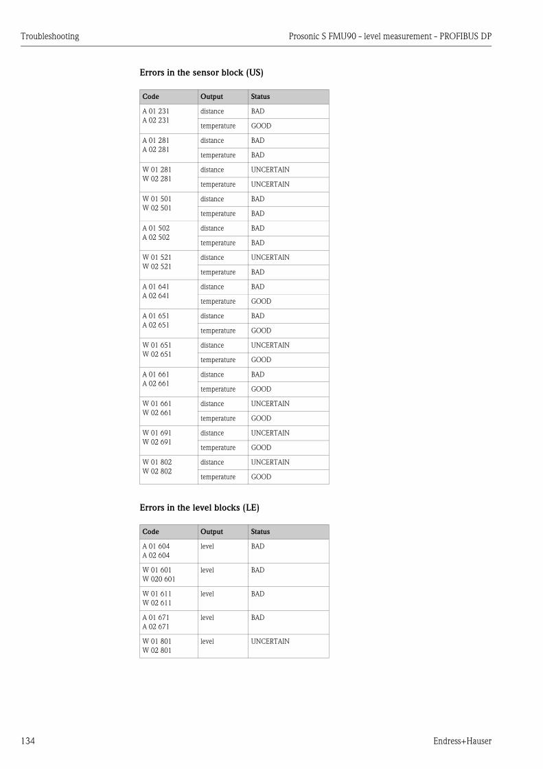
Troubleshooting Prosonic S FMU90 - level measurement - PROFIBUS DP
134 Endress+Hauser
Errors in the sensor block (US)
Errors in the level blocks (LE)
Code Output Status
A 01 231
A 02 231
distance BAD
temperature GOOD
A 01 281
A 02 281
distance BAD
temperature BAD
W 01 281
W 02 281
distance UNCERTAIN
temperature UNCERTAIN
W 01 501
W 02 501
distance BAD
temperature BAD
A 01 502
A 02 502
distance BAD
temperature BAD
W 01 521
W 02 521
distance UNCERTAIN
temperature BAD
A 01 641
A 02 641
distance BAD
temperature GOOD
A 01 651
A 02 651
distance BAD
temperature GOOD
W 01 651
W 02 651
distance UNCERTAIN
temperature GOOD
A 01 661
A 02 661
distance BAD
temperature GOOD
W 01 661
W 02 661
distance UNCERTAIN
temperature GOOD
W 01 691
W 02 691
distance UNCERTAIN
temperature GOOD
W 01 802
W 02 802
distance UNCERTAIN
temperature GOOD
Code Output Status
A 01 604
A 02 604
level BAD
W 01 601
W 020 601
level BAD
W 01 611
W 02 611
level BAD
A 01 671
A 02 671
level BAD
W 01 801
W 02 801
level UNCERTAIN
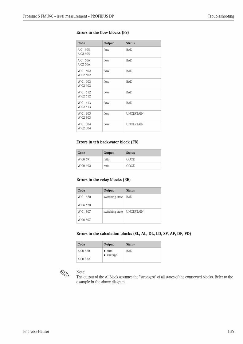
Prosonic S FMU90 - level measurement - PROFIBUS DP Troubleshooting
Endress+Hauser 135
Errors in the flow blocks (FS)
Errors in teh backwater block (FB)
Errors in the relay blocks (RE)
Errors in the calculation blocks (SL, AL, DL, LD, SF, AF, DF, FD)
! Note!
The output of the AI Block assumes the "strongest" of all states of the connected blocks. Refer to the
example in the above diagram.
Code Output Status
A 01 605
A 02 605
flow BAD
A 01 606
A 02 606
flow BAD
W 01 602
W 02 602
flow BAD
W 01 603
W 02 603
flow BAD
W 01 612
W 02 612
flow BAD
W 01 613
W 02 613
flow BAD
W 01 803
W 02 803
flow UNCERTAIN
W 01 804
W 02 804
flow UNCERTAIN
Code Output Status
W 00 691 ratio GOOD
W 00 692 ratio GOOD
Code Output Status
W 01 620
...
W 06 620
switching state BAD
W 01 807
...
W 06 807
switching state UNCERTAIN
Code Output Status
A 00 820
...
A 00 832
• sum
• average
BAD

Troubleshooting Prosonic S FMU90 - level measurement - PROFIBUS DP
136 Endress+Hauser
7.2 Possible calibration errors
Error Remedy
Incorrect measured value Check "actual distance"
a. "Actual distance" is incorrect
– For measurements in bypasses or ultrasound guide pipes:
Select the appropriate option in the "application parameters" parameter set.
– Perform tank map ("distance mapping")
b. "Actual distance" is correct
– Check "empty calibration" and "full calibration"
– Check the linearization
Measured value does not
change when filling or
emptying a vessel
a. Perform tank map (interference echo suppression)
b. clean sensor if necessary
c. choose better mounting position of the sensor (to avoid interference echos)
With an uneven surface the
measured value jumps
sporadically to higher levels
a. Perform tank map (interference echo suppression)
b. Select "turbulent surface" or "additional agitator" in the "process conditions"
parameter
c. Increase "output damping"
d. if possible: choose better mounting position and/or larger sensor
When filling the vessel, the
measured value sporadically
drops to lower levels
a. Change the "tank geometry" to "dome ceiling" or "horizontal cylinder"
("application parameters" parameter set)
b. If possible: avoid central mounting position of the sensor.
c. if possible: install sensor in bypass or ultrasound guide pipe.
Echo loss (Error E@@641) a. Check all settings in the "application parameters" parameter set.
b. if possible: choose better mounting position and/or larger sensor.
c. Align the sensor membrane parallely to the product surface (especially for solid
applications).
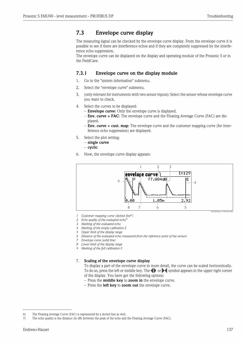
Prosonic S FMU90 - level measurement - PROFIBUS DP Troubleshooting
Endress+Hauser 137
7.3 Envelope curve display
The measuring signal can be checked by the envelope curve display. From the envelope curve it is
possible to see if there are interference echos and if they are completely suppressed by the interfe-
rence echo suppression.
The envelope curve can be displayed on the display and operating module of the Prosonic S or in
the FieldCare.
7.3.1 Envelope curve on the display module
1. Go to the "system information" submenu.
2. Select the "envelope curve" submenu.
3. (only relevant for instruments with two sensor inputs): Select the sensor whose envelope curve
you want to check.
4. Select the curves to be displayed:
– Envelope curve: Only the envelope curve is displayed.
– Env. curve + FAC: The envelope curve and the Floating Average Curve (FAC) are dis-
played.
– Env. curve + cust. map: The envelope curve and the customer mapping curve (for inter-
ference echo suppression) are displayed.
5. Select the plot setting:
– single curve
– cyclic
6. Now, the envelope curve display appears:
L00-FMU90xxx-19-00-00-en-083
1 Customer mapping curve (dotted line6))
2 Echo quality of the evaluated echo7)
3 Marking of the evaluated echo
4 Marking of the empty calibration E
5 Upper limit of the display range
6 Distance of the evaluated echo (measured from the reference point of the sensor)
7 Envelope curve (solid line)
8 Lower limit of the display range
9 Marking of the full calibration F
7. Scaling of the envelope curve display
To display a part of the envelope curve in more detail, the curve can be scaled horizontically.
To do so, press the left or middle key. The or symbol appears in the upper right corner
of the display. You have got the following options:
– Press the middle key to zoom in the envelope curve.
– Press the left key to zoom out the envelope curve.
8 6 5
9 4
1 2
7
3
6) The Floating Average Curve (FAC) is represented by a dotted line as well.
7) The echo quality is the distance (in dB) between the peak of the echo and the Floating Average Curve (FAC).

Troubleshooting Prosonic S FMU90 - level measurement - PROFIBUS DP
138 Endress+Hauser
L00-FMU90xxx-19-00-00-en-084
8. Moving the envelope curve display
To move the envelope curve display, press the right key a second time. The or symbol
appears in the upper right corner of the display. You have got the following options:
– Press the middle key to move the envelope curve to the right.
– Press the left key to move the envelope curve to the left.
L00-FMU90xxx-19-00-00-en-085
9. Quitting the envelope curve display
Press to quit the envelope curve display.
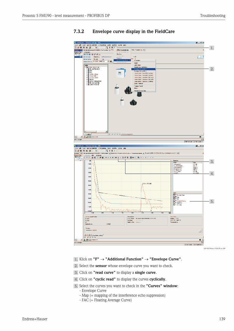
Prosonic S FMU90 - level measurement - PROFIBUS DP Troubleshooting
Endress+Hauser 139
7.3.2 Envelope curve display in the FieldCare
L00-FMU90xxx-19-00-00-xx-208
Klick on "F" "Additional Function" "Envelope Curve".
Select the sensor whose envelope curve you want to check.
Click on "read curve" to display a single curve.
Click on "cyclic read" to display the curves cyclically.
Select the curves you want to check in the "Curves" window:
- Envelope Curve
- Map (= mapping of the interference echo suppression)
- FAC (= Floating Average Curve)
1.
2.
3.
4.
5.
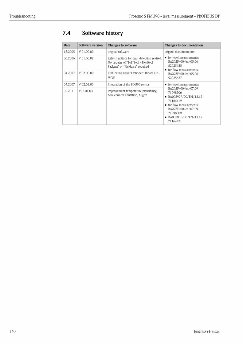
Troubleshooting Prosonic S FMU90 - level measurement - PROFIBUS DP
140 Endress+Hauser
7.4 Software history
Date Software version Changes to software Changes to documentation
12.2005 V 01.00.00 original software original documentation:
• for level measurements:
BA292F/00/en/05.06
52025635
• for flow measurements:
BA293F/00/en/05.06
52025637
06.2006 V 01.00.02 Relay functions for limit detection revised.
No updates of "ToF Tool - Fieldtool
Package" or "Fieldcare" required
04.2007 V 02.00.00 Einführung neuer Optionen: Binäre Ein-
gänge
04.2007 V 02.01.00 Integration of the FDU90 sensor • for level measurements:
BA292F/00/en/07.09
71098306
• BA00292F/00/EN/13.12
71164419
• for flow measurements:
BA293F/00/en/07.09
71098309
• BA00293F/00/EN/13.12
71164421
05.2011 V02.01.03 Improvement temperature plausibility;
flow counter limitation; bugfix

Prosonic S FMU90 - level measurement - PROFIBUS DP Maintenance
Endress+Hauser 141
8 Maintenance
8.1 Exterior cleaning
When cleaning the exterior, always use cleaning agents that do not attack the surface of the housing
and the seals.
8.2 Repairs
The Endress+Hauser repair concept assumes that the measuring devices have a modular design and
that customers are able to undertake repairs themselves ä 142, "Spare Parts". For more
information on service and spare parts, please contact your Endress+Hauser sales representative.
8.3 Repairs to Ex-approved devices
When carrying out repairs to Ex-approved devices, please note the following:
• Repairs to Ex-approved devices may only be carried out by trained personnel or by the
Endress+Hauser Service.
• Comply with the prevailing standards, national Ex-area regulations, safety instructions (XA) and
certificates.
• Only use original spare parts from Endress+Hauser.
• When ordering a spare part, please note the device designation on the nameplate. Only replace
parts with identical parts.
• Carry out repairs according to the instructions. On completion of repairs, carry our the specified
routine test on the device.
• Only Endress+Hauser Service may convert a certified device into a different certified variant.
• Document all repair work and conversions.
8.4 Replacement
After a complete instrument or electronic module has been replaced, the parameters can be
downloaded into the instrument again via the communication interface. Prerequisite to this is that
the data were uploaded to the PC beforehand using FieldCare. Measurement can continue without
having to carry out a new setup. Only a linearisation and a tank map (interference echo suppression)
have to be recorded again.
8.5 Replacing a sensor
Sensors can be replaced if required.
After replacing a sensor, the following parameters of the "basic setup" submenu must be checked:
• for sensors FDU8x: sensor type
(sensors of the type FDU9x are automatically detected by the Prosonic S)
• the empty calibration
• for level measurements: the full calibration
• the interference echo suppression
After that, the measurement can be continued without further restrictions.
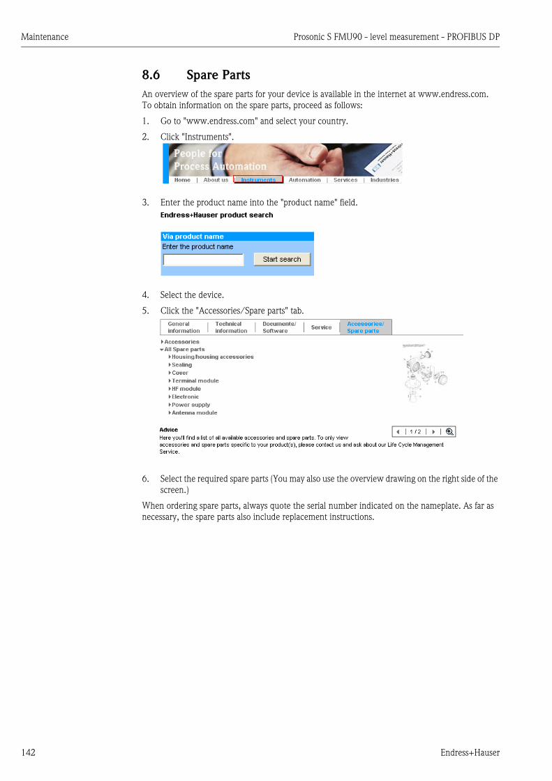
Maintenance Prosonic S FMU90 - level measurement - PROFIBUS DP
142 Endress+Hauser
8.6 Spare Parts
An overview of the spare parts for your device is available in the internet at www.endress.com.
To obtain information on the spare parts, proceed as follows:
1. Go to "www.endress.com" and select your country.
2. Click "Instruments".
3. Enter the product name into the "product name" field.
4. Select the device.
5. Click the "Accessories/Spare parts" tab.
6. Select the required spare parts (You may also use the overview drawing on the right side of the
screen.)
When ordering spare parts, always quote the serial number indicated on the nameplate. As far as
necessary, the spare parts also include replacement instructions.

Prosonic S FMU90 - level measurement - PROFIBUS DP Maintenance
Endress+Hauser 143
8.7 Return
Returning devices
The measuring device must be returned if repairs or a factory calibration are required, or if the
wrong measuring device has been ordered or delivered. According to legal regulations, End-
ress+Hauser, as an ISO-certified company, is required to follow certain procedures when handling
returned products that are in contact with medium.
To ensure swift, safe and professional device returns, please read the return procedures and condi-
tions on the Endress+Hauser website at www.services.endress.com/return-material
8.8 Disposal
In case of disposal please seperate the different components according to their material consistence.
8.9 Contact addresses of Endress+Hauser
Contact addresses can be found on our homepage: www.endress.com/worldwide. If you have any
questions, please contact your Endress+Hauser sales representative.
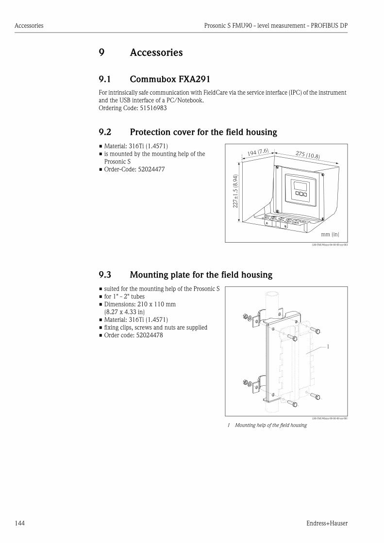
Accessories Prosonic S FMU90 - level measurement - PROFIBUS DP
144 Endress+Hauser
9 Accessories
9.1 Commubox FXA291
For intrinsically safe communication with FieldCare via the service interface (IPC) of the instrument
and the USB interface of a PC/Notebook.
Ordering Code: 51516983
9.2 Protection cover for the field housing
9.3 Mounting plate for the field housing
• Material: 316Ti (1.4571)
• is mounted by the mounting help of the
Prosonic S
• Order-Code: 52024477
L00-FMU90xxx-06-00-00-xx-003
275 (10.8)
22
7±
1.5
(8.9
4)
194 (7.6)
mm (in)
• suited for the mounting help of the Prosonic S
• for 1" - 2" tubes
• Dimensions: 210 x 110 mm
(8.27 x 4.33 in)
• Material: 316Ti (1.4571)
• fixing clips, screws and nuts are supplied
• Order code: 52024478
L00-FMU90xxx-00-00-00-xx-001
1 Mounting help of the field housing
1
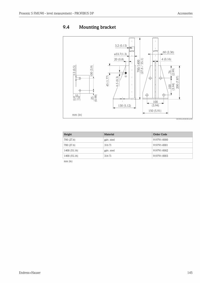
Prosonic S FMU90 - level measurement - PROFIBUS DP Accessories
Endress+Hauser 145
9.4 Mounting bracket
L00-FMUxx-00-00-00-xx-005
3.2 (0.13)
20 (0.8)
55(2.17)
10
0(3
.9)
25
(0.9
8)
70
0/1
40
0(2
7.6
/5
5.1
)
45
(1.7
7)
76
(2.9
9)
10
0(3
.94
)
20
0(7
.87
)
13
(0.5
)
ø33.7(1.3)
130 (5.12)
150 (5.91)
100(3.94)
60 (2.36)
4 (0.16)
6.5
(0.3
)mm (in)
Height Material Order Code
700 (27.6) galv. steel 919791-0000
700 (27.6) 316 Ti 919791-0001
1400 (55.16) galv. steel 919791-0002
1400 (55.16) 316 Ti 919791-0003
mm (in)

Accessories Prosonic S FMU90 - level measurement - PROFIBUS DP
146 Endress+Hauser
9.5 Adaption plate for remote display
Option:
Adaption plate 160x160 mm, thickness 3mm, aluminum, opening 92 x 92 mm (3.62 x 3.62 in) for
remote display of the FMU90 (size of the display: 96 x 96 mm (3.78 x 3.78 in)).
Can be used to replace the FMU86x remote display or DMU2160/2260.
Order Code: TSPFU 0390
Please contact your Endress+Hauser sales representative.
9.6 Overvoltage protection (in IP66 housing)
• Overvoltage protection for the mains voltage and up to 3 signal outputs
• Dimensions of housing: 292 x 253 x 106 mm (11.5 x 9.96 x 4.17 in)
• Order Code: 215095-0001
Used to mount the remote display into the
opening (138 x 138 mm (5.43 x 5.43 in)) of the
remote display module of the Prosonic
FMU860/861/862 (Display size:
144 x 144 mm (5.67 x 5.67 in)).
Order-Code: 52027441
! Note!
The adapter plate will be mounted directly in
the old remote display of the FMU86x series.
The housing of the remote display of FMU860/
861/862 is the holder for the adapter plate and
the new remote display of the FMU90/95 in the
format 96 x 96 mm (3.78 x 3.78 in).
L00-FMU90xxx-00-00-00-xx-001
1 Remote display of the Prosonic S with adaption plate
2 Opening of the remote display FMU860/861/862
1
2
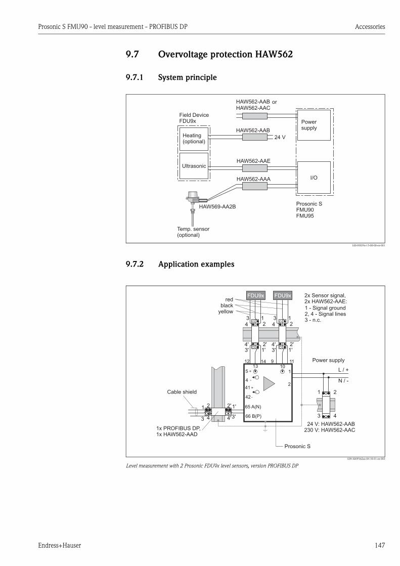
Prosonic S FMU90 - level measurement - PROFIBUS DP Accessories
Endress+Hauser 147
9.7 Overvoltage protection HAW562
9.7.1 System principle
L00-FMU9x-15-00-00-en-001
9.7.2 Application examples
G09-HAW562xx-04-10-01-en-003
Level measurement with 2 Prosonic FDU9x level sensors, version PROFIBUS DP
Prosonic SFMU90FMU95
or
12 14 9 11
1
2
42
41
4
513 10
L / +
N / -
24 V: HAW562-AAB230 V: HAW562-AAC
12
34
1'2'
3'4'
12
34
1'2'
3'4'
1 2
3 466 B(P)
65 A(N)1'2'
3'4'
1 2
3 4
1x PROFIBUS DP,1x HAW562-AAD
FDU9xFDU9x
Prosonic S
2x Sensor signal,2x HAW562-AAE:red
blackyellow
1 - Signal ground2, 4 - Signal lines3 - n.c.
Cable shield
Power supply
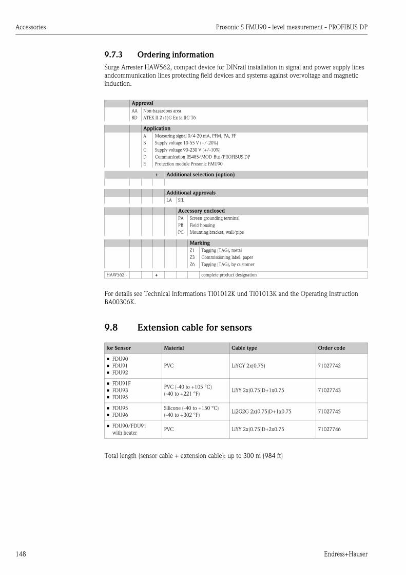
Accessories Prosonic S FMU90 - level measurement - PROFIBUS DP
148 Endress+Hauser
9.7.3 Ordering information
Surge Arrester HAW562, compact device for DINrail installation in signal and power supply lines
andcommunication lines protecting field devices and systems against overvoltage and magnetic
induction.
For details see Technical Informations TI01012K und TI01013K and the Operating Instruction
BA00306K.
9.8 Extension cable for sensors
Total length (sensor cable + extension cable): up to 300 m (984 ft)
Approval
AA Non-hazardous area
8D ATEX II 2 (1)G Ex ia IIC T6
Application
A Measuring signal 0/4-20 mA, PFM, PA, FF
B Supply voltage 10-55 V (+/-20%)
C Supply voltage 90-230 V (+/-10%)
D Communication RS485/MOD-Bus/PROFIBUS DP
E Protection module Prosonic FMU90
+ Additional selection (option)
Additional approvals
LA SIL
Accessory enclosed
PA Screen grounding terminal
PB Field housing
PC Mounting bracket, wall/pipe
Marking
Z1 Tagging (TAG), metal
Z3 Commissioning label, paper
Z6 Tagging (TAG), by customer
HAW562 - + complete product designation
for Sensor Material Cable type Order code
• FDU90
• FDU91
• FDU92
PVC LiYCY 2x(0.75) 71027742
• FDU91F
• FDU93
• FDU95
PVC (-40 to +105 °C)
(-40 to +221 °F)LiYY 2x(0.75)D+1x0.75 71027743
• FDU95
• FDU96
Silicone (-40 to +150 °C)
(-40 to +302 °F)Li2G2G 2x(0.75)D+1x0.75 71027745
• FDU90/FDU91
with heaterPVC LiYY 2x(0.75)D+2x0.75 71027746

Prosonic S FMU90 - level measurement - PROFIBUS DP Accessories
Endress+Hauser 149
9.9 Temperature sensor FMT131
L00-FMU90xxx-00-00-00-xx-002a
A Temperature sensor FMT131
B Weather protector
Product structure
Weather protection cover for FMT131
Order code: 942046-0000
67 (2.64)
Pg16
11
0(4
.33
)1
20
(4.7
3)
ø10 (0.4)
G1/2 AISO 228
25
(1.0
)
G1/2
12
(0.5
)1
10
(4.3
3)
A
B
25 x 1.5(1 x 0.09 )
010 Approval
R Non-hazardous area
J ATEX II 2G EEx m II T6/T5
Q FM Cl.I Div. 1 Gr. A-D, zone 1, 2
U CSA General Purpose (in preperation)
S CSA Class I Div. 1
020 Cable length
1 5 m/16 ft
2 10 m/ 32 ft
3 15 m/49 ft
4 20 m/65 ft
5 25 m/82 ft
6 30 m/98 ft
7 w/o cable, gland Pg16, IP66
8 ... m
A ... ft
995 Marking
1 Tagging (TAG)
FMT131 - complete product designation
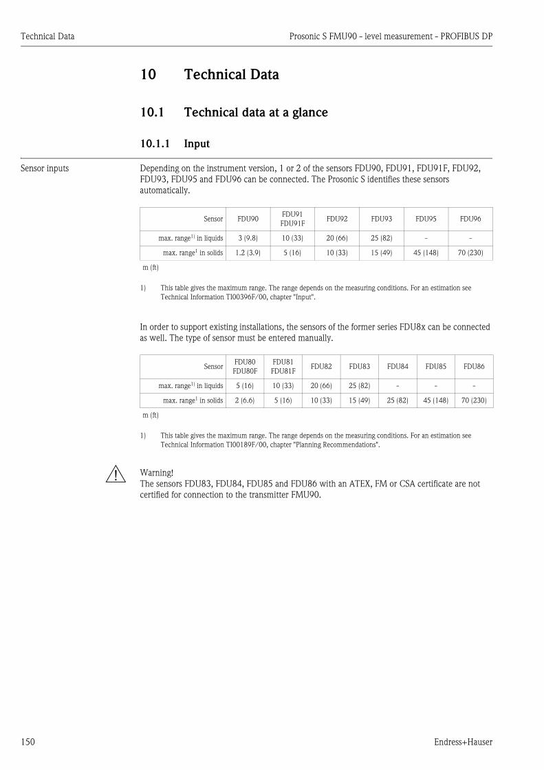
Technical Data Prosonic S FMU90 - level measurement - PROFIBUS DP
150 Endress+Hauser
10 Technical Data
10.1 Technical data at a glance
10.1.1 Input
Sensor inputs Depending on the instrument version, 1 or 2 of the sensors FDU90, FDU91, FDU91F, FDU92,
FDU93, FDU95 and FDU96 can be connected. The Prosonic S identifies these sensors
automatically.
In order to support existing installations, the sensors of the former series FDU8x can be connected
as well. The type of sensor must be entered manually.
# Warning!
The sensors FDU83, FDU84, FDU85 and FDU86 with an ATEX, FM or CSA certificate are not
certified for connection to the transmitter FMU90.
Sensor FDU90FDU91
FDU91FFDU92 FDU93 FDU95 FDU96
max. range1) in liquids
1) This table gives the maximum range. The range depends on the measuring conditions. For an estimation see
Technical Information TI00396F/00, chapter "Input".
3 (9.8) 10 (33) 20 (66) 25 (82) - -
max. range1 in solids 1.2 (3.9) 5 (16) 10 (33) 15 (49) 45 (148) 70 (230)
m (ft)
SensorFDU80
FDU80F
FDU81
FDU81FFDU82 FDU83 FDU84 FDU85 FDU86
max. range1) in liquids
1) This table gives the maximum range. The range depends on the measuring conditions. For an estimation see
Technical Information TI00189F/00, chapter "Planning Recommendations".
5 (16) 10 (33) 20 (66) 25 (82) - - -
max. range1 in solids 2 (6.6) 5 (16) 10 (33) 15 (49) 25 (82) 45 (148) 70 (230)
m (ft)
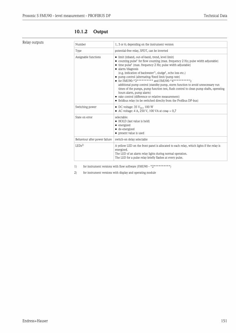
Prosonic S FMU90 - level measurement - PROFIBUS DP Technical Data
Endress+Hauser 151
10.1.2 Output
Relay outputsNumber 1, 3 or 6; depending on the instrument version
Type potential-free relay, SPDT, can be inverted
Assignable functions • limit (inband, out-of-band, trend, level limit)
• counting pulse for flow counting (max. frequency 2 Hz; pulse width adjustable)
• time pulse (max. frequency 2 Hz; pulse width adjustable)
• alarm/diagnosis
(e.g. indication of backwater1), sludge, echo loss etc.)
• pump control (alternating/fixed limit/pump rate)
• for FMU90-*3********** and FMU90-*4**********):
additional pump control (standby pump, storm function to avoid unnecessary run
times of the pumps, pump function test, flush control to clean pump shafts, operating
hours alarm, pump alarm)
• rake control (difference or relative measurement)
• fieldbus relay (to be switched direclty from the Profibus DP-bus)
1) for instrument versions with flow software (FMU90 - *2**********)
Switching power • DC voltage: 35 VDC, 100 W
• AC voltage: 4 A, 250 V, 100 VA at cos = 0,7
State on error selectable:
• HOLD (last value is held)
• energized
• de-energized
• present value is used
Behaviour after power failure switch-on delay selectable
LEDs2)
2) for instrument versions with display and operating module
A yellow LED on the front panel is allocated to each relay, which lights if the relay is
energized.
The LED of an alarm relay lights during normal operation.
The LED for a pulse relay briefly flashes at every pulse.

Technical Data Prosonic S FMU90 - level measurement - PROFIBUS DP
152 Endress+Hauser
PROFIBUS DP interfaceProfile 3.0
Transmittable values • main value (level or flow, depending on the instrument version)
• distances
• counters
• temperatures
• average/difference/sum
• relay states
• rake control
• pump control
Function blocks • 10 Analog Input Blocks (AI)
• 10 Digital Input Blocks (DI)
• 10 Digital Output Blocks (DO)
Supported baud rates • 9.6 kbaud
• 19.2 kbaud
• 45,45 kbuad
• 93.75 kbaud
• 187.5 kbaud
• 500 kbaud
• 1.5 Mbaud
• 3 Mbaud
• 6 Mbaud
• 12 Mbaud
Service Access Points (SAPs) 1
ID number 1540 (hex) 1540 (hex) = 5440 (dec)
GSD file EH3x1540.gsd
Addressing via dip switches at the instrument or via software (e.g. FieldCare)
Default address: 126 per software
Termination can be activated/deactivated in the instrument
Locking The device can be locked by hardware or software.

Prosonic S FMU90 - level measurement - PROFIBUS DP Technical Data
Endress+Hauser 153
10.1.3 Power supply
Supply voltage/
Power consumption/
Current consumption
Galvanic isolation The following terminals are galvanically isolated from each other:
• auxiliary energy
• sensor inputs
• analogue output 1
• analogue output 2
• relay outputs
• bus connection (PROFIBUS DP)
Fuse • 2 A T /DC
• 400 mA T /AC
accesible in the terminal compartment
10.1.4 Performance characteristics
Reference operating
conditions
• Temperature = 24±5 °C (75±9 °F)
• Pressure = 960±100 mbar (14±1.45 psi)
• Relative humidity = 60±15 %
• Ideally reflecting surface, sensor vertically aligned
(e.g. calm, plane liquid surface of 1 m2 (10.76 ft2))
• No interference echoes within the signal beam
• Settings of the application parameters:
– tank shape = flat ceiling
– medium property = liquid
– process condition = calm surface
Measuring uncertainty8) ±0,2 % of the maximum span of the sensor
Typical accuracy9) ±2 mm (0.08 in) + 0.17 % of the measured distance
Measured value resolution 1 mm (0.04 in) with FDU90/FDU91
Measuring frequency max. 3 Hz
The exact value depends on the settings of the application parameters and the instrument version.
! Note!
The maximum measuring frequency is obtained for "empty E" 2 m (6.6 ft) and "process
condition" = "test: no filter".
Instrument version Supply voltage Power consumption Current consumption
AC voltage
(FMU90 - ****A****)90 to 253 VAC (50/60 Hz) max. 23 VA max. 100 mA at 230 VAC
DC voltage
(FMU90 - ****B****)10,5 to 32 VDC max. 14 W (typically 8 W) max. 580 mA at 24 VDC
8) according to NAMUR EN 61298-2
9) after calibration

Technical Data Prosonic S FMU90 - level measurement - PROFIBUS DP
154 Endress+Hauser
Influence of the vapor pressure The vapor pressure at 20 °C (68 °F) gives a hint on the accuracy of the ultrasonic level
measurement. If the vapor pressure at 20 °C (68 °F) is below 50 mbar (1 psi), ultrasonic level
measurement is possible with a very high accuracy. This is valid for water, aqueous solutions, water-
solid-solutions, dilute acids (hydrochloric acid, sulfuric acid, ...), dilute bases (caustic soda, ...), oils,
greases, slurries, pastes, ...
High vapor pressures or outgassing media (ethanol, acetone, ammonia, ...) can influence the
accuracy. If conditions like these are present, please contact the Endress+Hauser support.
10.1.5 Environment
Ambient temperature -40 to 60 °C (-40 to 140 °F)
The functionality of the LC display becomes restricted at TU < -20 °C ( TU < -4 °F).
If the device is operated outdoors in strong sunlight, a protective cover should be used ( ä 144,
"Accessories").
Storage temperature -40 to 60 °C (-40 to 140 °F)
Climate class • Field housing: according to DIN EN 60721-3 4K2/4K5/4K6/4Z2/4Z5/4C3/4S4/4M2
(DIN 60721-3 4K2 corresponds to DIN 60654-1 D1)
• Housing for DIN rail mounting: according to
DIN EN 60721-3 3K3/3Z2/3Z5/3B1/3C2/3S3/3M1
(DIN 60721-3 3K3 corresponds to DIN 60654-1 B2)
Vibration resistance • Housing for DIN rail: DIN EN 60068-2-64 / IEC 68-2-64; 20 to 2000 Hz; 0,5 (m/s2)2/Hz
• Field housing: DIN EN 60068-2-64 / IEC 68-2-64; 20 to 2000 Hz; 1,0 (m/s2)2/Hz
Ingress protection • Field housing: IP66 / NEMA 4x
• Housing for DIN rail: IP20
• separate display:
– IP65 / NEMA 4 (front panel , if mounted in cabinet door)
– IP20 (rear panel, if mounted in cabinet door)
Electromagnetic compatibility
(EMC)
• Electromagnetic compatibility according to all relevant requirements of the EN 61326- series and
NAMUR recommendation EMC (NE21). For details see declaration of conformity.
• With respect to interference emission the devices meet the requirements of class A and are only
provided for use in an "industrial environment"!

Prosonic S FMU90 - level measurement - PROFIBUS DP Technical Data
Endress+Hauser 155
10.1.6 Mechanical construction
Dimensions ä 10, "Installation"
Weight
Materials
Housing version Weight
Field housing approx. 1.6 to 1.8 kg (3.53 to 3.97 lbs); depending on instrument version
Housing for DIN rail approx. 0.5 to 0.7 kg (1.10 to 1.54 lbs); depending on instrument version
( ä 12 "Dimensions of the DIN-rail housing")
separate display and operating
moduleapprox. 0.5 kg (1.10 lbs)
Part Material
Housing bracket PC-FR
Field housing PC-FR
Housing for DIN rail PBT-GF
For details see Technical Information TI00397F/0.
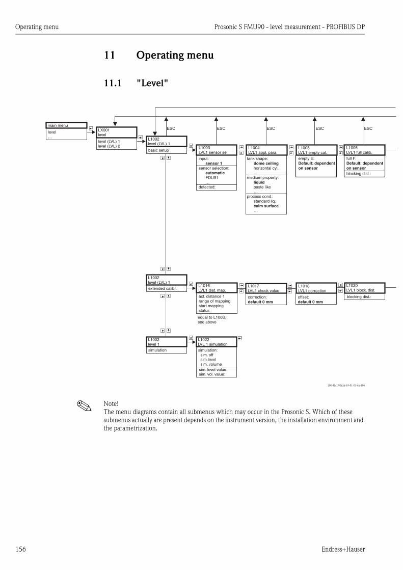
Operating menu Prosonic S FMU90 - level measurement - PROFIBUS DP
156 Endress+Hauser
11 Operating menu
11.1 "Level"
L00-FMU90xxx-19-01-01-en-106
! Note!
The menu diagrams contain all submenus which may occur in the Prosonic S. Which of these
submenus actually are present depends on the instrument version, the installation environment and
the parametrization.
full F:Default: dependenton sensor
main menu
level…
LX001level
level (LVL) 1level (LVL) 2
L1002level (LVL) 1
basic setupL1003LVL1 sensor sel.
L1004LVL1 appl. para.
L1005LVL1 empty cal.
L1006LVL1 full calib.
L1002level (LVL) 1
extended calibr.L1017LVL1 check value
L1018LVL1 correction
L1002level 1simulation
input:
sensor selection:
FDU91…
detected:
sensor 1
automatic
tank shape:
horizontal cyl....
medium property:
paste like…
process cond.:standard liq.
…
dome ceiling
liquid
calm surface
L1016LVL1 dist. map.
act. distance 1range of mappingstart mappingstatus
L1022LVL 1 simulationsimulation:
sim. offsim.levelsim. volume
empty E:Default: dependenton sensor
correction:default 0 mm
offset:default 0 mm
ESC ESC ESC ESC ESC
blocking dist.:
L1020LVL1 block. dist.
blocking dist.:
sim. level value:sim. vol. value:
equal to L100B,see above

Prosonic S FMU90 - level measurement - PROFIBUS DP Operating menu
Endress+Hauser 157
L00-FMU90xxx-19-01-02-en-106
*only for device version with additional switch inputs (FMU90-********B***)
limitation:off
high limitlow/high limit
upper limit:lower limit:
low limit
L1007LVL1 unit
L1008LVL1 linearisat.
L100Dedit
L100BLVL1 dist. map.
type:
L100CLVL1 state
customer unitdiametermax. scalemodecustomer unitintermed. heightmax. scalemode
customer uniteditstatus tablemode
none
linear
horizontal cyl.sphere
pyramid bottomconical bottomangled bottom
table
unit level:
m…
level 1:distance:
% (default)
customer unitmax. scalemode
customer unit:
l…
mode:
ullage
%
level
table editor
act. distance 1:range of mapping:start mapping:status: yes
level 1:act. distance:status:
L1019LVL1 limitation
ESC ESC ESC ESC ESC
L100BLVL 1 check value
act. distance 1:check distance:- dist. too big- dist. unknown- distance = ok- dist. too small- manual
- read- manual- semi-automatic- delete
input 1:
ext. digin 1...ext. digin 4
function:offMin (0%)Max (100%)holdcustomer spec.
(value:)
disabled
fieldbus DO1...fieldbus DO10
L1020LVL1 ext. input 1
input 2:
ext. digin 1...ext. digin 4
function:offMin (0%)Max (100%)holdcustomer spec.
(value:)
disabled
fieldbus DO1...fieldbus DO10
L1021LVL1 ext. input 2
*
**
*
**
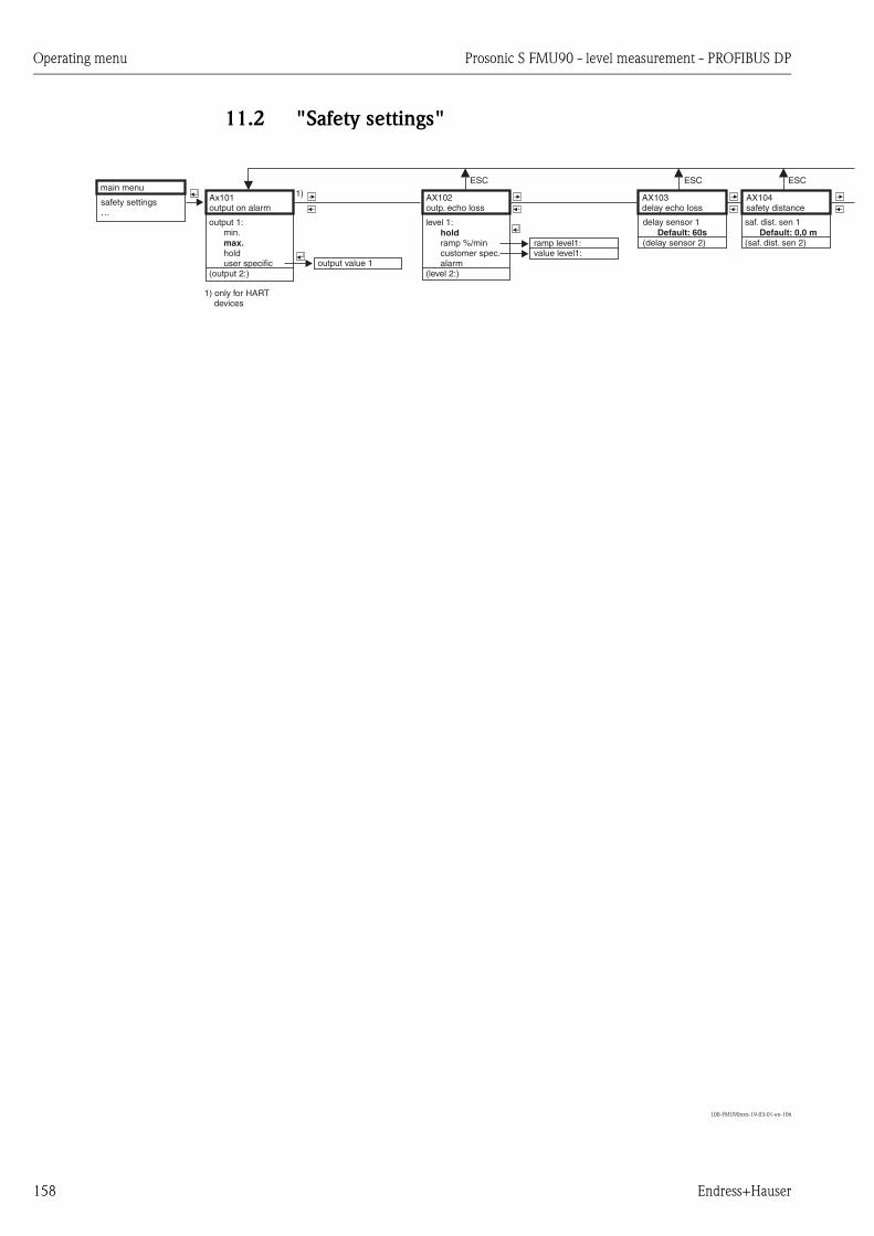
Operating menu Prosonic S FMU90 - level measurement - PROFIBUS DP
158 Endress+Hauser
11.2 "Safety settings"
L00-FMU90xxx-19-03-01-en-106
saf. dist. sen 1
(saf. dist. sen 2)Default: 0,0 m
main menu
safety settings…
Ax101output on alarm
output 1:min.
holduser specific
(output 2:)
max.
output value 1
AX102outp. echo loss
level 1:
ramp %/mincustomer spec.alarm
(level 2:)
hold
AX103delay echo loss
AX104safety distance
delay sensor 1
(delay sensor 2)Default: 60s
ESC ESC ESC
value level1:ramp level1:
1)
1) only for HARTdevices
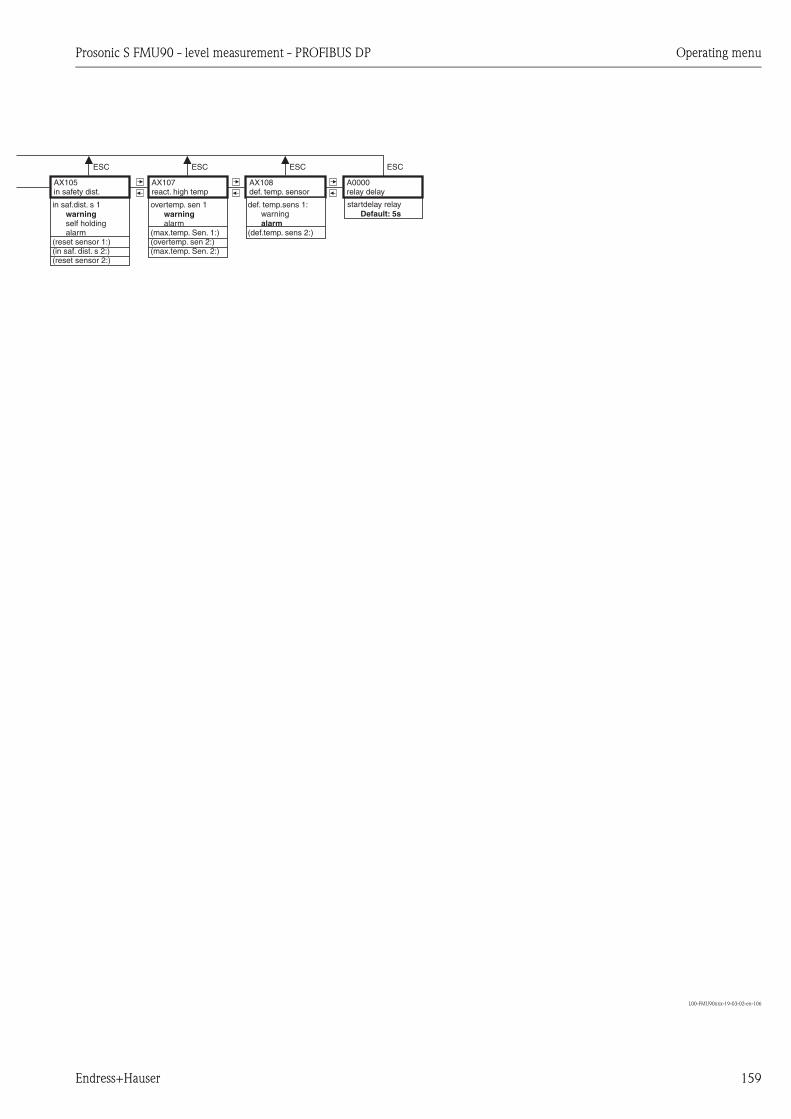
Prosonic S FMU90 - level measurement - PROFIBUS DP Operating menu
Endress+Hauser 159
L00-FMU90xxx-19-03-02-en-106
in saf.dist. s 1
self holdingalarm
(reset sensor 1:)(in saf. dist. s 2:)(reset sensor 2:)
warning
AX107react. high temp
A0000relay delay
AX108def. temp. sensor
AX105in safety dist.
overtemp. sen 1
alarm(max.temp. Sen. 1:)(overtemp. sen 2:)(max.temp. Sen. 2:)
warningdef. temp.sens 1:
warning
(def.temp. sens 2:)alarm
startdelay relayDefault: 5s
ESC ESCESC ESC
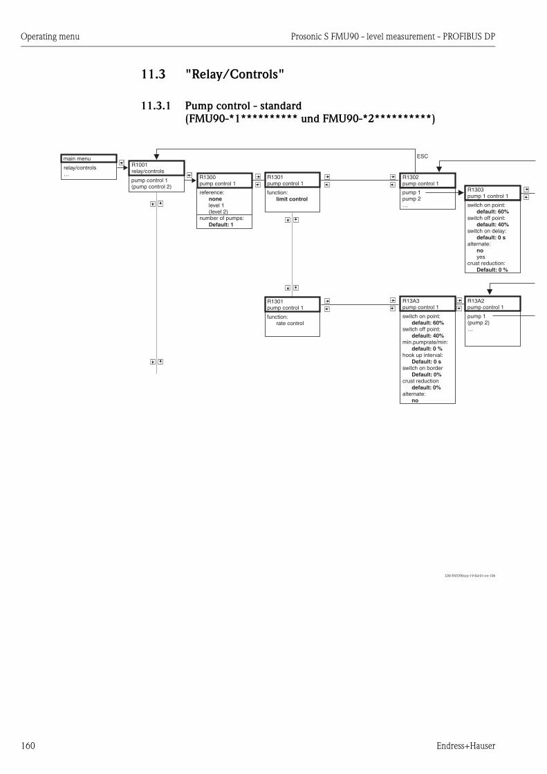
Operating menu Prosonic S FMU90 - level measurement - PROFIBUS DP
160 Endress+Hauser
11.3 "Relay/Controls"
11.3.1 Pump control - standard
(FMU90-*1********** und FMU90-*2**********)
L00-FMU90xxx-19-04-01-en-106
main menu
relay/controls…
R1001relay/controls
pump control 1(pump control 2)
R1300pump control 1
R1301pump control 1
function:limit control
reference:
level 1(level 2)
number of pumps:
none
Default: 1
R1302pump control 1
pump 12
…pump
R1303pump 1 control 1
switch on point:
switch off point:
switch on delay:
alternate:
yescrust reduction:
default: 60%
default: 40%
default: 0 s
no
Default: 0 %
ESC
R13A3pump control 1
switch on point:
switch off point:
min.pumprate/min:
hook up interval:
switch on border
crust reduction
alternate:
default: 60%
default: 40%
default: 0 %
Default: 0 s
Default: 0%
default: 0%
no
R13A2pump control 1
pump 1(pump 2)…
R1301pump control 1
function:rate control

Prosonic S FMU90 - level measurement - PROFIBUS DP Operating menu
Endress+Hauser 161
L00-FMU90xxx-19-04-02-en-106
function:
pump 1 control 1…
invert
yes
none
no
R1306relay 2
RX305relay allocation
relay 1:relay 2:…
ESC
R13A3pump1 control1
switch on delay:backl. interval:backlash time:error handling:
holdswitch onswitch off
0s0h0s
actual value
relay 1relay 2...
RX3A5relay allocation
ESCR1304pump 1 control 1
backl. interval:
backlash time:
error handling:
switch onswitch offactual value
default: 0 h
default: 0 s
hold
ESC
function:
invert:none
no
R23A6relay 2
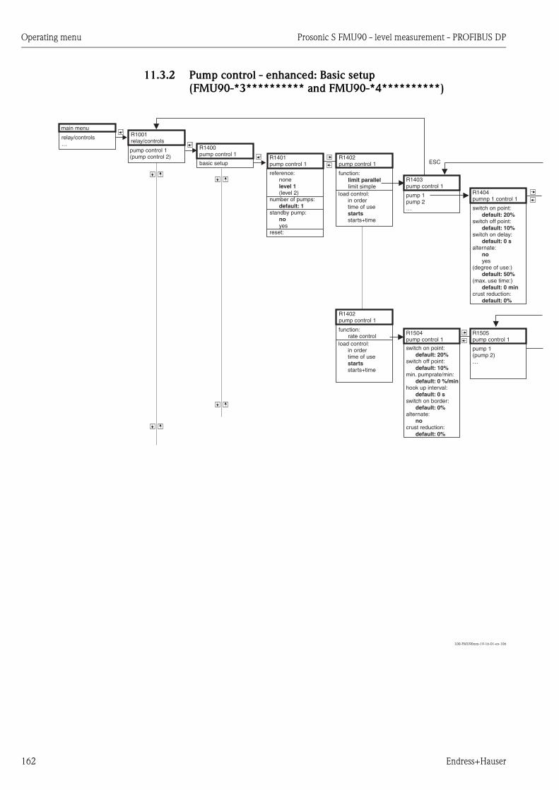
Operating menu Prosonic S FMU90 - level measurement - PROFIBUS DP
162 Endress+Hauser
11.3.2 Pump control - enhanced: Basic setup
(FMU90-*3********** and FMU90-*4**********)
L00-FMU90xxx-19-16-01-en-106
main menu
relay/controls…
R1001relay/controls
pump control 1(pump control 2) R1401
pump control 1R1402pump control 1
function:
limit simplelimit parallel
reference:none
(level 2)number of pumps:
standby pump:
yesreset:
level 1
default: 1
no
R1403pump control 1
pump 1pump 2…
R1404pumnp 1 control 1
switch on point:
switch off point:
switch on delay:
alternate:
yes(degree of use:)
(max. use time:)
crust reduction:
default: 20%
default: 10%
default: 0 s
no
default: 50%
default: 0 min
default: 0%
ESC
R1504pump control 1
switch on point:
switch off point:
min. pumprate/min:
default: 20%
default: 10%
default: 0 %/minhook up interval:
switch on border:
alternate:
crust reduction:
default: 0 s
default: 0%
no
default: 0%
R1505pump control 1
pump 1(pump 2)…
R1400pump control 1
basic setup
load control:in ordertime of use
starts+timestarts
R1402pump control 1
function:rate control
load control:in ordertime of use
starts+timestarts
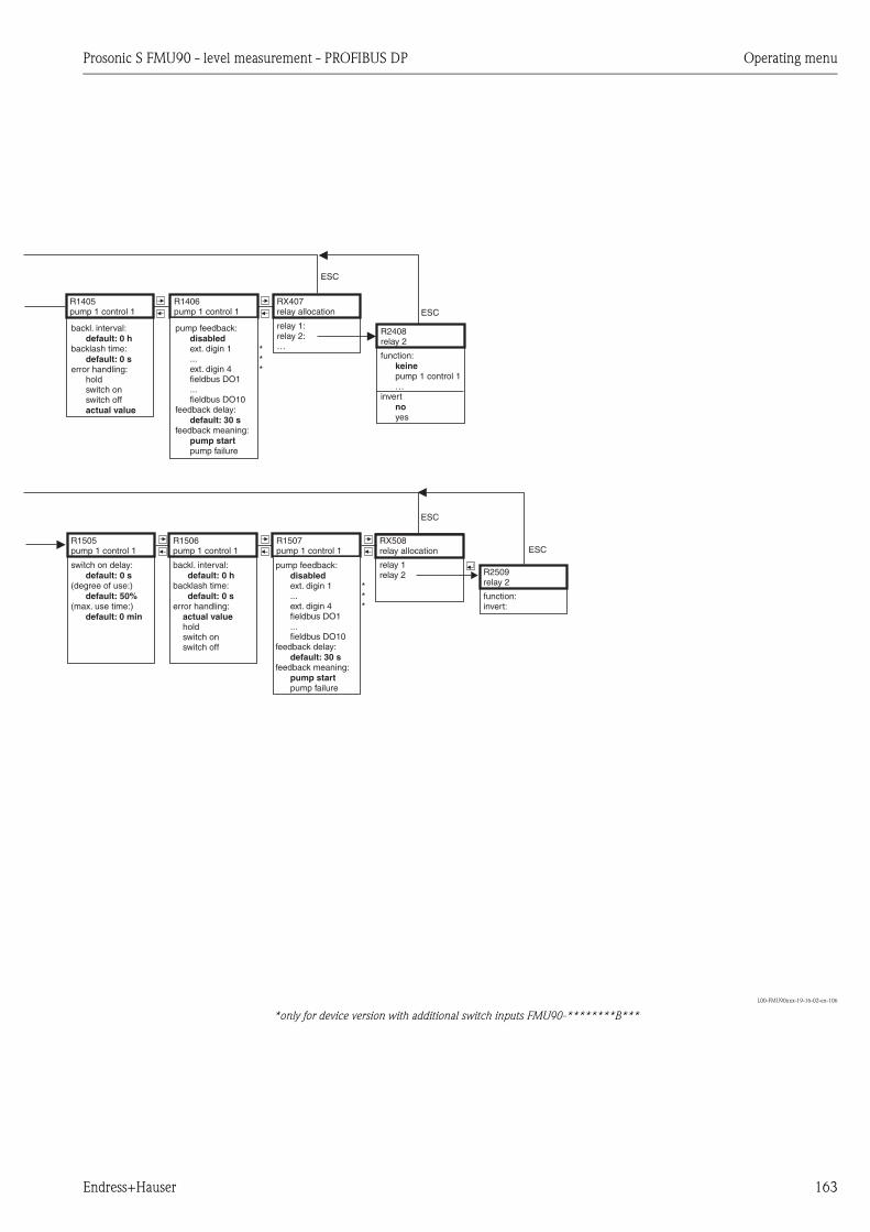
Prosonic S FMU90 - level measurement - PROFIBUS DP Operating menu
Endress+Hauser 163
L00-FMU90xxx-19-16-02-en-106
*only for device version with additional switch inputs FMU90-********B***
function:
pump 1 control 1…
invert
yes
keine
no
R2408relay 2
RX407relay allocation
relay 1:relay 2:…
ESC
relay 1relay 2
RX508relay allocation
R1505pump 1 control 1
switch on delay:
(degree of use:)
(max. use time:)
default: 0 s
default: 50%
default: 0 min
function:invert:
R2509relay 2
ESCR1405pump 1 control 1
backl. interval:
backlash time:
error handling:holdswitch onswitch off
default: 0 h
default: 0 s
actual value
ESC
ESC
R1406pump 1 control 1
pump feedback:
feedback delay:
feedback meaning:
pump failure
disabled
default: 30 s
pump start
ext. digin 1...ext. digin 4fieldbus DO1...fieldbus DO10
R1506pump 1 control 1
backl. interval:
backlash time:
error handling:
holdswitch onswitch off
default: 0 h
default: 0 s
actual value
R1507pump 1 control 1
pump feedback:
feedback delay:
feedback meaning:
pump failure
disabled
default: 30 s
pump start
ext. digin 1...ext. digin 4fieldbus DO1...fieldbus DO10
*
**
*
**

Operating menu Prosonic S FMU90 - level measurement - PROFIBUS DP
164 Endress+Hauser
11.3.3 Pump control - enhanced: additional functions
(FMU90*3********** and FMU90-*4**********)
L00-FMU90xxx-19-17-01-en-106
*only for device version with additional switch inputs (FMU90-********B***)
R1400pump control 1
storm functionR1601storm function 1
storm function:
onswitch on point:switch off point:storm time:
off
95%90%
60 min
R1400pump control 1
function testR1602function test 1
function test:
onmax downtime:max. test time:swtich on point:switch off point:
off
0 h60 s20%10%
R1400pump control 1
flush controlR1603flush control 1
flush control:
onpump cycles:flush cycles:flush time:flush delay:
off
00
0 s0 s
R1400pump control 1
tariff controlR1607tariff control 1
tariff control:
yestariff input:
disabled
no
ext. digin 1...ext. digin 4fieldbus DO1...fieldbus DO10
R1608tariff control 1
pump 1pump 2...
RX604relay allocation
relay 1relay 2...
R2605relay 2
function:invert:...
R2605function
- none- flush ctrl 1
R1619tariff ctrl 1 p1
switch on point:switch on point:switch off point:switch off point:
20%20%10%10%
R1400pump control 1
pump dataR1610pump data 1
pump 1pump 2...
R1611pump data 1 p1
operating hours:reset op. hours:total op. hours:number of starts:starts per hour:backlash starts:reset backlstart:lasat run time:
R1400pump control 1 1
R1612op. hours alarm 1
op. hours alarm
onalarm delay:
off
0 s
R1613op. hours alarm 1
pump 1pump 2...
R1613op. hours alarm1 p1
operating hours:max. op. hours
default: 10000 h
RX614relay allocation
relay 1relay 2...
R2615relay 2
function:invert:...
R2615function
- none- op. hour alarm 1
R1400pump control 1
pump alarmR1617pump alarm 1
pump alarm
onwaiting time:
off
0 s
RX618relay allocation
relays 1relay 2...
R2619relay 2
function:invert:...
R2619function
- none- pump alarm 2
op. hours alarm
***
*

Prosonic S FMU90 - level measurement - PROFIBUS DP Operating menu
Endress+Hauser 165

Operating menu Prosonic S FMU90 - level measurement - PROFIBUS DP
166 Endress+Hauser
11.3.4 Rake control/Relay configuration/Simulation
L00-FMU90xxx-19-11-01-en-106
R0000relay/controls
relay configurat. RX101relay allocation
R2103relay 2
function:+ additional params,depend. on function
R2107select function
relay 1:relay 2:…
limitR2018function
limit level 1limit level 2limit lvl. 1+2…
R2103relay 2
function:limit type:
inbandout of bandtendeny/speed
+ additional params,depending onlimit type
standard A
time pulse
BCD
E
counting pulse R201Bfunction
pulse flow 1pulse flow 2…
F
alarm/diagnost. R201Dfunction
nonealarm relaydiagnosticsbackwat. alarmdirt alarm
GHIJ
R1001relay/controls
relay simulation RX120relay simulation
R2106relay 2
simulation:
onsimulation value:
switch on
off
switch off
relay 1:relay 2:…
field bus R201Efunction
noneDO1...DO10
switch delay:
error handling:
holdswitch onswitch off
default: 0 s
actual value
R1001relay/controls
rake control R1200rake control
R1201rake control
upstream water:
level 1level 2
downstream water:
level 1level 2
function:
ratio
none
none
difference
switch on point:
switch off point:default: 20% / 0.8
default: 10% / 0.9
R1202rake control
relay 1:relay 2:…
RX203relay allocation
function:
rake control…
invert
yes
none
no
R2204relay allocation
ESC
1)
1) only for PROFIBUS DPinstruments

Prosonic S FMU90 - level measurement - PROFIBUS DP Operating menu
Endress+Hauser 167
L00-FMU90xxx-19-08-02-en-106
R2103relay 2
function:limit xxxx
limit type:standard
switch on point:
switch off point:default: 60%
default: 40%
R2104relay 2
switch delay:
invert.
yeserror handling:
holdswitch onswitch off
default: 0 s
no
actual value
AR2103relay 2
limit:limit xxxx
limit type:inband/out of bd.
upper switchpt.:
low switch point:
hysteresis
default: 60%
default: 40%
default: 1%
R2104relay 2
switch delay:
invert:
yeserror handling:
holdswitch onswitch off
default: 0 s
no
actual value
B/C
R2103relay 2
function:limit xxxx
limit type:tendency/speed
switch on /min:
switch off /min:default: 60%
default: 40%
R2104relay 2
switch delay:
invert:
yeserror handling:
holdswitch onswitch off
default: 0 s
no
actual value
R2103relay 2
function:time pulse
pulse width:default: 200 ms
pulse time:default: 1 min
R2104relay 2
invert
yeserror handling:
stop
no
actual value
E
R2103relay 2
function:pulse flow 1
counter unit:
l…
pulse value:
pulse width:
m3
default: 1.000 m3
default: 200 ms
R2105relay 2
pulse counter:overflow x 10^7:reset counter
yesstart counter:
stop counter:
no
default: 0%
default: 100%
R2104relay 2
invert:
yeserror handling:
holdstop
no
actual value
R2104relay 2
invert:
yesno
G
R2103relay 2
function:diagnostics
allocation 1:
echoloss sen 1…
allocation 2:
echoloss sen 2…
none
none
R2104relay 2
invert:
yesno
R2104relay 2
invert:
yesno
IR2104relay 2
invert:
yesno
J
D
F
H

Operating menu Prosonic S FMU90 - level measurement - PROFIBUS DP
168 Endress+Hauser
11.4 "Output/calculations"
L00-FMU90xxx-19-12-01-en-106
measured value 1:value:status:
main menu
output calculat.…
O1000output/calculat
analog input OXA01output/calculat.
O1A02analog input 1analog input 1
...analog input 10
OXB01output/calculat
O1B03digital input 1
allocation 1:value:status:
digital input 1...digital input 10
O1C01Profibus DP
O1C11ident number
profile version:instrument addr.:ident number:
profilemanufacturer
O1A02output
nonelevel 1...flow 1...average level...
digital input
Profibus DP
O1B02Digital Eingang 1
Pumpensteuerung 1Pumpensteuerung 2
O1B02Pumpensteuerung 1
keine FunktionPumpe 1 PST 1...Pumpe N PST 1
O1B02additional inputs
noneext. digin 1...ext. digin 4
additional inputs
O1B02relay
nonerelay 1...relay 6
relay
O1B02reset
noyes
reset
rake control O1B02rake control
nonerake control

Prosonic S FMU90 - level measurement - PROFIBUS DP Operating menu
Endress+Hauser 169
11.5 "Device properties"
L00-FMU90xxx-19-06-01-en-106
controls:
pump controlrake controle
nooperating mode:
level+flowflowflow+backwater
leveltemperature unit:
°F°C
main menu
device properties…
D1001device properties
operating param. D1101distance unit
D110Btemperature unit
D110Coperating mode
D110Dcontrols
distance unit:
ftmminch
m
tag marking D1102tag marking
output 1:output 2:device marking:
D1103language
language:English…
language
password/reset D1104password/reset
reset:(s. manual)
code:(s. manual)
status:
1)1)
2)
2) only for operating modes
"level" and "level +flow"
1) only for HART instruments
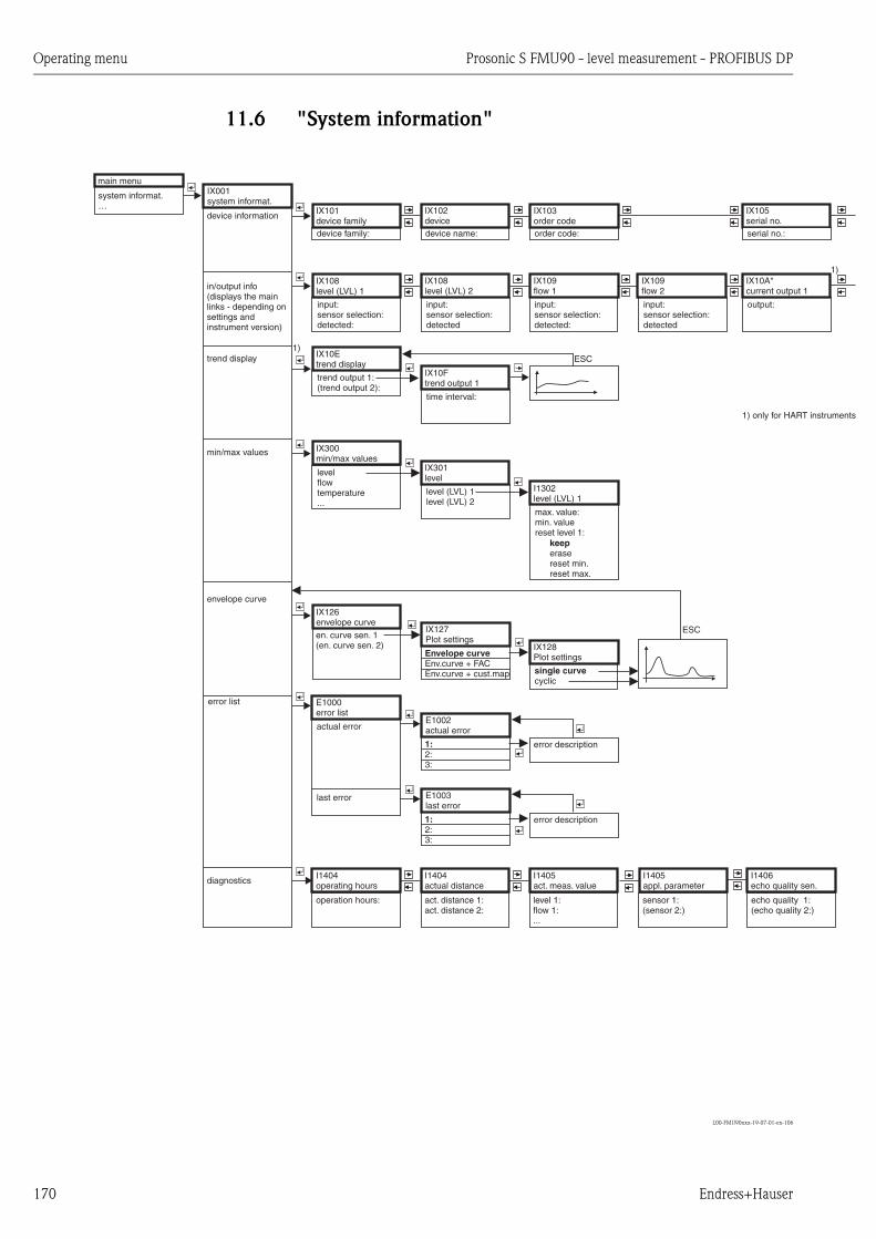
Operating menu Prosonic S FMU90 - level measurement - PROFIBUS DP
170 Endress+Hauser
11.6 "System information"
L00-FMU90xxx-19-07-01-en-106
actual error
max. value:min. valuereset level 1:
erasereset min.reset max.
keep
levelflowtemperature...
output:input:sensor selection:detected
input:sensor selection:detected
input:sensor selection:detected:
main menu
system informat.…
IX001system informat.
device information
E1000error list
error description
I1404operating hours
I1405act. meas. value
en. curve sen. 1(en. curve sen. 2)
IX108level (LVL) 1
IX108level (LVL) 2
IX105serial no.
IX109flow 1
IX109flow 2
IX10A*current output 1
I1405appl. parameter
I1406echo quality sen.
IX126envelope curve
IX127Plot settings
in/output info(displays the mainlinks - depending onsettings andinstrument version)
input:sensor selection:detected:
trend output 1:(trend output 2):
IX10Etrend display
trend display
time interval:
IX10Ftrend output 1
IX300min/max values
I1302level (LVL) 1
min/max values
Envelope curveEnv.curve + FACEnv.curve + cust.map single curve
cyclic
IX128Plot settings
envelope curve
diagnostics
operation hours: level 1:flow 1:...
sensor 1:(sensor 2:)
echo quality 1:(echo quality 2:)
error list
E1002actual error
1:2:3:
error description
E1003last error
1:2:3:
last error
level (LVL) 1level (LVL) 2
IX301level
device family: device name: order code:
IX103order code
IX102device
IX101device family
serial no.:
ESC
ESC
I1404actual distance
act. distance 1:act. distance 2:
1)
1)
1) only for HART instruments
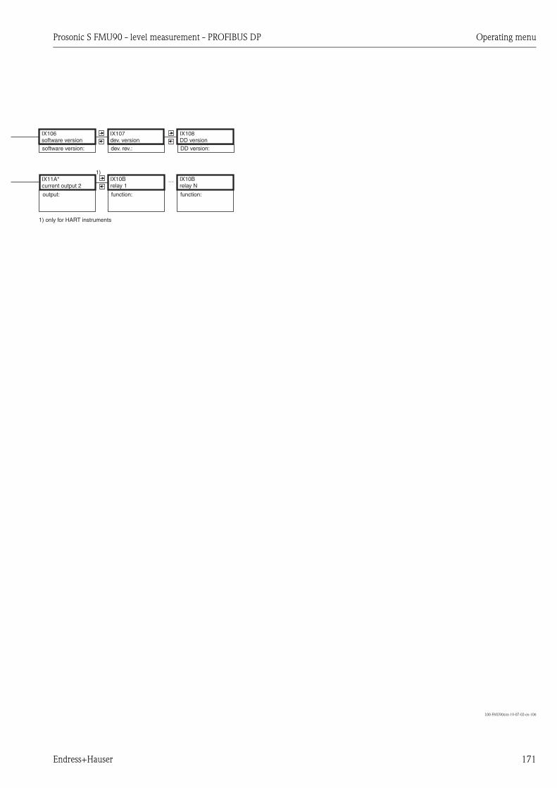
Prosonic S FMU90 - level measurement - PROFIBUS DP Operating menu
Endress+Hauser 171
L00-FMU90xxx-19-07-02-en-106
function:function:output:
IX106software version
IX107dev. version
IX11A*current output 2
IX10Brelay 1
IX10Brelay N
…
software version: dev. rev.:
IX108DD versionDD version:
1)
1) only for HART instruments

Operating menu Prosonic S FMU90 - level measurement - PROFIBUS DP
172 Endress+Hauser
11.7 "Display"
L00-FMU90xxx-19-09-01-en-106
11.8 "Sensor management"
L00-FMU90xxx-19-10-01-en-106
*only for device version with additional switch inputs and connected external temperature sensor
FMU90-********B***)
main menu
display…
DX200back to home
back to home:default: 900 s
DX201display format
format:
ft-in-1/16"no. of decimals:
sep. character:
commacustomized text:
decimal
default: x.xx
point
DX202display
type:
…(value 1:)(cust. text 1:)…
1xvalue + bargr.
1)1)
1) depending on type
main menu
sensor management…
D1106US sensor 1
sensor operation:
holdoff
sensor priority:detected:sensor selection:detection window:
on
DX019input
FDU sensor 1(FDU sensor 2)
D1107US sensor 1
temp. measurement:
extern. temp.avg.USsens/ext
ext. send ctrl.:offholdvalue
input:disabled
(distance:)
US sensor
ext. digin 1...ext. digin 4fieldbus DO1...fieldbus DO10
D1021ext. temp. sensor
max. value:min. value:actual value:reset:
erasereset min.reset max.
keep
D1020ext. temp. sensor
sensor type:no sensorFMT131PT100
temperature unit:
D1018FDU sensor
ext. temp. sensor D1022ext. temp. sensor
error handling:
warningvalue at warning:
alarm
default: 20 °C
D1025external digin
invert:
yesno
DX024external digin
external diginexternal digin 2external digin 3external digin 4
1
D1018FDU sensor
external digin
D1018FDU sensor
sensor management
*
*
*

Prosonic S FMU90 - level measurement - PROFIBUS DP Appendix
Endress+Hauser 173
12 Appendix
12.1 Default block configuration
The Prosonic S contains various function blocks. During the commissioning procedure the blocks
are linked to each other in order to perform the desired measuring task. Depending on the instru-
ment version and installation environment, the following function blocks may occur:
Signal input
• Ultrasonic Sensor Block (US)
• Digitial Output Block (DO)
Measured value calculation
• Level Block (LE)
• Flow Block (FS)
• Flow Block with Backwater Detection (FB)
• Flow Block with Averaged Level (FA)
Siganl output
• Analog Input Block (AI)
• Digital Input Block (DI)
Calculations
• Sum Block Level (SL)
• Average Block Level (AL)
• Difference Block Level 1 - 2 (DL)
• Difference Block Level 2 - 1 (LD)
• Sum Block Flow (SF)
• Average Block Flow (AF)
• Difference Block Flow 1 - 2 (DF)
• Difference Block Flow 2 - 1 (FD)
Counters
• Totalizator Block (TO)
• Daily Counter Block (DC)
• Impulse Counter (IC)
Limits
• Limit Block (LS)

Appendix Prosonic S FMU90 - level measurement - PROFIBUS DP
174 Endress+Hauser
12.1.1 Operating Mode = " Level"
1 sensor input
L00-FMU90xxx-19-00-00-en-097
2 sensor inputs
L00-FMU90xxx-19-00-00-en-100
FDU9x
US1 LE1 AI1
AI2
AI3temperature
distancebus
FDU9x
FDU9x
US1
US2
LE1
LE2
AI1
AI2
temperature
temperature
distance
distance
AI3
AI4
AI5
AI6
LS1
LS2
LS3
LS4
LS5
LS6
SL
AL
DL
AI7
AI8
AI9

Prosonic S FMU90 - level measurement - PROFIBUS DP
Endress+Hauser 175

Prosonic S FMU90 - level measurement - PROFIBUS DP
176 Endress+Hauser

Prosonic S FMU90 - level measurement - PROFIBUS DP Index
Endress+Hauser 177
Index
Symbols"analog input N" (N = 1 - 10) . . . . . . . . . . . . . . . . . . . . . 123
"back to home" . . . . . . . . . . . . . . . . . . . . . . . . . . . . . . . . 128
"digital input N" (N = 1 - 10). . . . . . . . . . . . . . . . . . . . . . 122
"display format" . . . . . . . . . . . . . . . . . . . . . . . . . . . . . . . . 127
"display" . . . . . . . . . . . . . . . . . . . . . . . . . . . . . . . . . . . . . 126
"LVL N application parameters" (N = 1 or 2) . . . . . . . . . . . 59
"LVL N check value" (N = 1 or 2) . . . . . . . . . . . . . . . . . . . 69
"LVL N distance mapping" (N = 1 or 2) . . . . . . . . . . . . . . . 70
"LVL N empty calibration" (N = 1 or 2) . . . . . . . . . . . . . . . 61
"LVL N full calibration" (N = 1 or 2) . . . . . . . . . . . . . . . . . 61
"LVL N linearisation" (N = 1 or 2) . . . . . . . . . . . . . . . . . . . 64
"LVL N sensor selection" (N = 1 or 2) . . . . . . . . . . . . . . . . 58
"LVL N state" (N = 1 or 2) . . . . . . . . . . . . . . . . . . . . . . . . . 70
"pump control N" (N = 1 or 2). . . . . . 85–86, 90, 98–99, 105
"pump M/control N" (M = 1 - 6, N = 1 or 2) . . 86, 88, 100,
102–103
"Pumpensteuerung N" (N = 1 oder 2) . . . 106–108, 110–115
"rake control" . . . . . . . . . . . . . . . . . . . . . . . . . . . . . 117, 119
"Relais N" (N = 1 - 6) (Pumpensteuerung) . . . . . . . . 109, 114
"Relaiszuordnung" (Pumpensteuerung) . . . . . . 109, 114–115
"relay allocation" . . . . . . . . . . . . . . . . . . . . . . . . . . . . . 72, 77
"relay allocation" (rake control) . . . . . . . . . . . . . . . . . . . . 120
"relay N" (N = 1 - 6) (alarm/diagnostics) . . . . . . . . . . . 78–79
"relay N" (N = 1 - 6) (limit) . . . . . . . . . . . . . . . . . . . . . 73, 76
"relay N" (N = 1 - 6) (rake control) . . . . . . . . . . . . . . . . . 120
"unit level" . . . . . . . . . . . . . . . . . . . . . . . . . . . . . . . . . . . . 62
AAcyclic data exchange . . . . . . . . . . . . . . . . . . . . . . . . . . . . 35
Adaption plate for remote display. . . . . . . . . . . . . . . . . . . 146
Adaption plate for remote display module . . . . . . . . . . . . . 16
Ambient conditions . . . . . . . . . . . . . . . . . . . . . . . . . . . . . 154
Auxiliary energy . . . . . . . . . . . . . . . . . . . . . . . . . . . . . . . 153
BBasic setup . . . . . . . . . . . . . . . . . . . . . . . . . . . . . . . . . . . . 56
Block configuration (Default) . . . . . . . . . . . . . . . . . . . . . . 173
CCable entries . . . . . . . . . . . . . . . . . . . . . . . . . . . . . . . . . . . 17
Calibration errors . . . . . . . . . . . . . . . . . . . . . . . . . . . . . . 136
CE mark . . . . . . . . . . . . . . . . . . . . . . . . . . . . . . . . . . . . . . . 9
cleaning . . . . . . . . . . . . . . . . . . . . . . . . . . . . . . . . . . . . . 141
Commubox FXA291 . . . . . . . . . . . . . . . . . . . . . . . . . . . . 144
Ddeclaration of conformity. . . . . . . . . . . . . . . . . . . . . . . . . . . 9
Device address . . . . . . . . . . . . . . . . . . . . . . . . . . . . . . . . . 49
DIN-rail housing . . . . . . . . . . . . . . . . . . . . . . . . . . . . . . 6, 12
Display and operating module . . . . . . . . . . . . . . . . . . . . . . 36
EEnvelope curve . . . . . . . . . . . . . . . . . . . . . . . . . . . . . . . . 137
Error codes . . . . . . . . . . . . . . . . . . . . . . . . . . . . . . . . . . . 130
Error signal . . . . . . . . . . . . . . . . . . . . . . . . . . . . . . . . . . . 129
Extension cable for sensors . . . . . . . . . . . . . . . . . . . . . . . 148
Ffield housing . . . . . . . . . . . . . . . . . . . . . . . . . . . . . . . . . 6, 10
FieldCare. . . . . . . . . . . . . . . . . . . . . . . . . . . . . . . . . . . . . . 48
First setup . . . . . . . . . . . . . . . . . . . . . . . . . . . . . . . . . . . . . 54
FXA291. . . . . . . . . . . . . . . . . . . . . . . . . . . . . . . . . . . . . . 144
GGSD files . . . . . . . . . . . . . . . . . . . . . . . . . . . . . . . . . . . . . . 51
IIncoming acceptance . . . . . . . . . . . . . . . . . . . . . . . . . . . . . 10
Input . . . . . . . . . . . . . . . . . . . . . . . . . . . . . . . . . . . . . . . . 150
Interference echo suppression . . . . . . . . . . . . . . . . . . . . . . 68
LLinearisation . . . . . . . . . . . . . . . . . . . . . . . . . . . . . . . . . . . 64
Locking . . . . . . . . . . . . . . . . . . . . . . . . . . . . . . . . . . . . . . . 52
MMechanical construction . . . . . . . . . . . . . . . . . . . . . . . . . 155
Mounting bracket . . . . . . . . . . . . . . . . . . . . . . . . . . . . . . 145
Mounting plate for the field housing. . . . . . . . . . . . . . . . . 144
NNameplate. . . . . . . . . . . . . . . . . . . . . . . . . . . . . . . . . . . . . . 7
OOperating menu (navigation) . . . . . . . . . . . . . . . . . . . . . . . 40
Operational safety . . . . . . . . . . . . . . . . . . . . . . . . . . . . . . . . 4
Output . . . . . . . . . . . . . . . . . . . . . . . . . . . . . . . . . . . . . . 151
Overvoltage protection . . . . . . . . . . . . . . . . . . . . . . . . . . 146
PPerformance characteristics . . . . . . . . . . . . . . . . . . . . . . . 153
Potential equalization . . . . . . . . . . . . . . . . . . . . . . . . . . . . 32
process safety . . . . . . . . . . . . . . . . . . . . . . . . . . . . . . . . . . . 4
Product structure. . . . . . . . . . . . . . . . . . . . . . . . . . . . . . . . . 8
Produktstruktur . . . . . . . . . . . . . . . . . . . . . . . . . . . . . . . . 148
Protection cover for field housing. . . . . . . . . . . . . . . . . . . 144
RRake control . . . . . . . . . . . . . . . . . . . . . . . . . . . . . . . . . . 116
range of mapping (parameter) . . . . . . . . . . . . . . . . . . . . . . 70
Relay (alarm/diagnostic) . . . . . . . . . . . . . . . . . . . . . . . . . . 77
Relay (fieldbus) . . . . . . . . . . . . . . . . . . . . . . . . . . . . . . . . 121
Relay (limit). . . . . . . . . . . . . . . . . . . . . . . . . . . . . . . . . . . . 72
remote display and operating module . . . . . . . . . . . . . . . 7, 15
repairs to Ex-approved devices. . . . . . . . . . . . . . . . . . . . . 141
Reset to default configuration. . . . . . . . . . . . . . . . . . . . . . . 53
SSafety conventions and symbols . . . . . . . . . . . . . . . . . . . . . . 5
Safety Instructions . . . . . . . . . . . . . . . . . . . . . . . . . . . . . . . . 4
Scope of delivery . . . . . . . . . . . . . . . . . . . . . . . . . . . . . . . . . 9
Sensor cable extension. . . . . . . . . . . . . . . . . . . . . . . . . . . . 24
Sensor cable shortening . . . . . . . . . . . . . . . . . . . . . . . . . . . 29
Sensor connection . . . . . . . . . . . . . . . . . . . . . . . . . . . . . . . 23

Prosonic S FMU90 - level measurement - PROFIBUS DP Index
178 Endress+Hauser
Sensor heater . . . . . . . . . . . . . . . . . . . . . . . . . . . . . . . . . . 25
Sensor mounting . . . . . . . . . . . . . . . . . . . . . . . . . . . . . . . . 16
separate display and operating module . . . . . . . . . . . . . . . . 31
Software history . . . . . . . . . . . . . . . . . . . . . . . . . . . . . . . 140
Spare Parts . . . . . . . . . . . . . . . . . . . . . . . . . . . . . . . . . . . 142
start mapping (parameter) . . . . . . . . . . . . . . . . . . . . . . . . . 70
Storage . . . . . . . . . . . . . . . . . . . . . . . . . . . . . . . . . . . . . . . 10
Synchronization line . . . . . . . . . . . . . . . . . . . . . . . . . . . . . 30
TTerminal assignment . . . . . . . . . . . . . . . . . . . . . . . . . . . . . 19
Trademarks . . . . . . . . . . . . . . . . . . . . . . . . . . . . . . . . . . . . . 9
Transport . . . . . . . . . . . . . . . . . . . . . . . . . . . . . . . . . . . . . 10
WWiring. . . . . . . . . . . . . . . . . . . . . . . . . . . . . . . . . . . . . . . . 17

Prosonic S FMU90 - level measurement - PROFIBUS DP Index
Endress+Hauser 179

www.endress.com/worldwide
BA00292F/00/EN/13.12
71164419
FM+SGML 9.0 71164419