Embed Size (px)
Citation preview
proSeal roof system specifications manual proSeal garden roof system
Issued 11/10/10 1
proSeal Roof SystemsTM ……ROOFTOP GARDEN SPECIFICATION
GUIDE SPECIFICATION FOR THE INSTALLATION OF AN INSULATED PROTECTED proSeal C3WATERPROOFING MEMBRANE IN A ROOFTOP GARDEN SYSTEM
1.0 GENERAL CONDITIONS
1.01 Description
A. Scope: To install a Loose Laid proSeal C3 Single-Ply Membrane with prefabricatedflashings and other items to comprise a waterproofing system.
B. Related Work: The work includes, but is not necessarily limited to the installation of:
1. Substrate preparation
2. Water Stop (where specified)
3. Leak Detection Drains (where specified)
4. Separation Sheet (where specified)
5. Waterproofing Membrane
6. Protection Layer
7. Insulation (Extruded Polystyrene)
8. Drainage Layer
9. Precast Concrete Pavers and Pedestals or Ballast
10. Prefabricated Flashings for Protrusions of Pipes
11. Fasteners
12. Clad Metal/Edge Metal & Detail Metal
13. Sealants and Adhesives
C. Related Work by others: The work includes, but is not necessarily limited to theinstallation of:
1. Soil
2. Retention grids (where specified)
3. Plants, trees, grasses etc.
4. Irrigation system (where specified)
5. Leak detection system (where specified)

proSeal roof system specifications manual proSeal garden roof system
Issued 11/10/10 2
D. Upon successful completion of the work, and depending on the chosen thickness ofproSeal C3 Single-Ply Membrane 60, or 80 mil, the following warranties may beobtained:
1. Commercial Limited Material Warranty (15 or 20 years)
2. Commercial Limited Labor and Material Warranty* (15 or 20 years)
*Labor Warranty by Installer (2 Years)
1.02 Quality Assurance
A. This roofing system shall be applied only by a contractor authorized by proSeal RoofSystemsTM prior to bid.
B. The roofing membrane used in proSeal Single-Ply waterproofing system shall be aproduct of a membrane manufacturer having over 20 years of waterproofing experience.
C. The installation of the waterproofing system, from the water stop to the installation of thedrainage layer shall be the responsibility of the waterproofing contractor.
D. Pre-construction meeting is to be held between the owner and/or the owner’srepresentative and/or the design professional, waterproofing contractor, generalcontractor and proSeal Roof SystemsTM
E. If a Manufacturer’s Labor and Material Warranty is requested, an inspection shall bemade by a representative of proSeal Roof SystemsTM, to observe the installation of thewaterproofing system. The representative will check and test all welded seams prior tothe installation of the separation layer, protection layers, insulation layers and drainagelayer. If any items are found to be deficient and cannot be corrected at the time ofinspection a punch list will be made and sent to the waterproofing contractor forcorrection. The waterproofing contractor will not proceed with the installation of theseparation layer, protection layers, insulation layers and drainage layer until thecompletion of any deficiencies in the waterproofing membrane. Upon completion of thepunch list items, the waterproofing contractor will inform proSeal Roof SystemsTM inwriting.
F. There shall be no deviation made from the contract specification or the approved shopdrawings without prior written approval from the owner and/or the owner’s representativeand/or the design professional and proSeal Roof SystemsTM.
G. The waterproofing contractor will conduct a 24 hour water test on the completedwaterproofing membrane prior to the installation of the separation layer, protection layers,insulation layers and drainage layer. The water test shall be witnessed and confirmed bythe owner and/or the owner’s representative and/or the design professional, thewaterproofing contractor, the general contractor and proSeal Roof SystemsTM.
H. Upon completion of the waterproofing project, the waterproofing contractor shall submit,to proSeal Roof SystemsTM, a Request for Inspection Form or Notice of CompletionForm, certifying that all work has been done in accordance with the contract specificationand proSeal Roof SystemsTM requirements.
1.04 Submittals
A. The waterproofing contractor shall submit to the owner's representative and/or the designprofessional the following:
1. Copies of specifications.

proSeal roof system specifications manual proSeal garden roof system
Issued 11/10/10 3
2. Written approval by the insulation manufacturer (as applicable) for use andperformance of the product in the proposed system.
3. Written approval by the drainage board manufacturer for use and performance ofthe product in the proposed system.
4. Specimen copy of proSeal Roof SystemsTM warranty.
5. Dimensioned shop drawings, which should include:
a. Outline of roof/s, dimensions & height of each building.
b. Special details not in the proSeal Roof SystemsTM Specification Manuel,summit for approval (use the System/Detail Deviation Request Form).
c. Technical acceptance from RPW Associates,Inc.
B. The roofing contractor shall submit to RPW Associates Technical Department.
1. For an L&M Warranty a completed Notice of Award, Roof Plan and non proSealRoof SystemsTM details prior to starting the project for technical approval.
2. For a Material Warranty, the commercial Material Request form is the only formrequired to summit to proSeal Roof SystemsTM.
1.05 Product Delivery, Storage, and Handling
A. All products delivered to the job site shall be in the original unopened containers orwrappings.
B. Handle all materials to prevent damage. Place all materials on pallets and fully protectfrom moisture. (Do not lay the materials directly on existing roofing)
C. Membrane rolls shall be stored lying down on pallets and fully protected from moisture.
D. Bonding adhesives shall be stored at temperatures above 40 F.
E. All flammable materials shall be stored in a cool, dry area away from sparks and openflames. Follow precautions outlined on container or supplied by RPW Associates.
F. Materials that are damaged are to be removed from the job site and are to be replaced atthe waterproofing contractor’s expense.
1.06 Job Conditions
A. Commence waterproofing only after the substrate preparation is complete and acceptedby the owner and/or the owner’s representative and/or design professional and RPWAssociates
B. The waterproofing contractor must obtain in writing from the owner, the owner’srepresentative, and the design professional that the structure can withstand theanticipated loads.
C. Only install as much new waterproofing and flashings as can be made watertight eachday.
D. All waterproofing shall be completed without exposing the building interior, its contents oremployees to inclement weather. Relative to the waterproofing project the contractorassumes all responsibility for maintaining the building in a dry condition during the project

proSeal roof system specifications manual proSeal garden roof system
Issued 11/10/10 4
E. All surfaces to receive new insulation, membrane, or flashings shall be thoroughly dry.Should surface moisture occur, the waterproofing contractor shall provide the necessaryequipment to dry the surface prior to installation.
F. Temporary water stops shall be installed at the end of each work day, and shall beremoved before proceeding with the next day's work.
G. Arrange work sequence to avoid use of newly constructed waterproofing for storage,walking surface, and equipment movement. Where such access is absolutely required,the waterproofing contractor shall provide all necessary protection and barriers tosegregate the work area and to prevent damage to adjacent areas.
H. Prior to and during application, all dirt, debris, and dust shall be removed from surfacesby vacuuming, sweeping, blowing with compressed air, and/or similar methods.
I. All new and existing roofing, insulation, flashings, adhesive cans, metal work, andgeneral construction debris shall be properly disposed of following all applicable local,state, and federal regulations.
J. The waterproofing contractor shall follow all safety regulations as recommended byOSHA.
K. The waterproofing contractor should take care during application and storage thatoverloading of the deck and structure does not occur.
L. Liquid materials such as solvents and adhesives shall be stored and used away fromopen flames, sparks, and excessive heat.
M. The waterproofing contractor shall verify that all drain lines are unblocked before startingwork. Report any such blockages to the owner's representative and proSeal RoofSystemsTM in writing.
N. If any unusual or concealed condition is discovered, stop work and notify the owner andRPW Associates immediately in writing.
O. All areas affected by construction activities shall be cleaned.
P. The waterproofing contractor should take necessary precautions when using proSealadhesives around air intakes. The smell of the adhesive could be a disturbance to thebuilding occupants. It is the roofing contractor's responsibility to coordinate equipment tobe turned off and on, with the owner, if necessary.
1.07 Bidding Requirements
Bidders need to visit the site and carefully examine any areas in question as to conditions thatcould possibly affect proper execution of the work. All dimensions and quantities shall bedetermined or verified by the contractor.

proSeal roof system specifications manual proSeal garden roof system
Issued 11/10/10 5
1.08 Warranties
A. Commercial Limited Material Warranty: 15 or 20 year warranties are available at nocharge to the owner.
B. Commercial Limited Labor and Material Warranty*: The manufacturer will warranty theproSeal Roof SystemsTM material, plus the labor for the reinstallation of new materials ifthe material becomes defective and leaks. These warranties may be issued on a feebasis for a period of 15 or 20 years. The cost of removal and replacement of overburdento expose the waterproofing membrane for inspection and repair is at the sole expense ofthe owner.
*The Roof Contractor will be responsible for (workmanship) labor for the first two yearsafter roof completion.
2.00 PRODUCTS
2.01 General
A. The proSeal roofing / waterproofing membranes and its related components confirmhaving over 25 years experience in producing PVC Single-Ply Membrane.
B. Any components other than those supplied or manufactured by proSeal Roof SystemsTM
may be submitted for review and acceptance.
2.02 Approved Membrane
A. proSeal C3 Single-Ply 60, or 80 mil nominal thickness, polyester-reinforced membrane.
B. Even thickness Top and Bottom film.
C. Acrylic Top Finish.
D. proSeal C3 Single-Ply Membrane shall conform to ASTM D4434 - 96 Standard forpolyvinyl chloride sheet roofing. Classification: Type 3.
E. Sheet size:60 mil 78” X 90’ (585 square feet)80 mil 78” X 75’ (487.5 square feet)
E. As manufactured, the membrane shall conform to the physical properties.

proSeal roof system specifications manual proSeal garden roof system
Issued 11/10/10 6
proSeal C3 Roofing Membranes: Typical Properties
Property Method Requirement 60 mil 80 milThickness [in]
ASTM D751 0.045 0.06 (+/-10%)
0.080 (+/-10%)
Breaking Strength [lbf/in.]MD
XMDASTM D751
A-Grab Method200200
465400
540480
Elongation @ Break [%]MD
XMDASTM D751
A-Grab Method15A
15A4038
4038
Retention of Propertiesafter Heat Ageing:
Breaking Strength [%]Elongation @ Break [%]
Tearing Strength [%]
ASTM D304580C for 56 days
90%Original
PassPassPass
PassPassPass
Tearing Strength [lbf]MD
XMD
ASTM D751B-Tongue Tear
Method4545
7360
7470
Low TemperatureBend [C]
ASTM D2136-40C Pass Pass Pass
Accelerated WeatheringCracking (7x Magnification)Crazing (7x Magnification)
Discoloration (Visual)
ASTM G535,000 h min
NoneNone
Negligible
NoneNone
Negligible
NoneNone
Negligible
Linear DimensionalChange [%] MD
XMD
ASTM D120480C for 56 days
for 6 hours0.50.5
-0.40.0
-0.40.0
Change in Weight AfterImmersion in Water [%]
ASTM D57070C for 168
hours3 1.2 1.2
Static PunctureResistance
ASTM D560233 lbf @ 23C Pass Pass Pass
Dynamic PunctureResistance
ASTM 563520J @ 23C Pass Pass Pass
Seam StrengthD751 75% 100% 100%
Warranty (years non-prorated) 15 Material 20 Material
A For reinforcing fabric only; elongation of PVC material shall be 250% MD and 220% XMD
The table presents typical properties of proSeal C3 roofing membranes. Requirements are taken from ASTMD4434-96.
Note: As well as ASTM D4434-96, proSealC3 roofing membranes meet the following standards:
1. Factory Mutual 4470
2. UL/ULC Class A
3. CAN/CGSB 37.54-95
proSeal roof system specifications manual proSeal garden roof system
Issued 11/10/10 7
2.03 Approved Membrane Accessories
A. Sealants and Pitch Pocket Fillers
1. The following caulking/sealants, as supplied by RPW Associates, are acceptableto use with the proSealC3 Single-Ply Membrane:
a. proSeal Polyurethane Caulking
b. proSeal Water Stop tape
c. proSeal Pitch Pan Filler
B. Adhesives
1. proSeal 1700 Adhesive
C. Drains
1. proSeal / Thaler Drain
D. Fasteners, Plates & Termination Bars
1. Corrosion-resistant screws, membrane plates, and termination bars as suppliedby RPW Associates.
E. Flashings
1. proSeal C3 Single-Ply polyester-reinforced membrane, as supplied by RPWAssociates.
F. Prefabricated Flashings
1. Inside/outside corners, cone flashings, as supplied by RPW Associates, Inc.G. PVC Coated Metal Flashings
1. .025 inch thick PVC membrane laminated to 24 ga. galvalume metal, as suppliedby RPW Associates, Inc.
2. Prefabricated Flashings
2.04 Separation, Protection and Drainage Layers
A. Drainage/Separation Sheet
1. proSeal Separation Sheet 4 oz polyester, as supplied by RPW Associates.
2. Roll Size: 15’” x 360’
3. Roll Weight: 220 lbs
4. As manufactured, drainage separation sheet shall conform to the followingphysical properties:
proSeal roof system specifications manual proSeal garden roof system
Issued 11/10/10 8
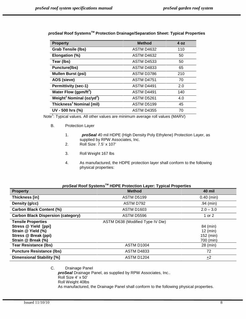
proSeal Roof SystemsTM Protection Drainage/Separation Sheet: Typical Properties
Property Method 4 ozGrab Tensile (lbs) ASTM D4632 110Elongation (%) ASTM D4632 50Tear (lbs) ASTM D4533 50Puncture(lbs) ASTM D4833 65Mullen Burst (psi) ASTM D3786 210AOS (sieve) ASTM D4751 70Permittivity (sec-1) ASTM D4491 2.0Water Flow (gpm/ft2) ASTM D4491 140Weight1 Nominal (oz/yd2) ASTM D5261 4.0Thickness1 Nominal [mil) ASTM D5199 45UV - 500 hrs (%) ASTM D4355 70
Note1: Typical values. All other values are minimum average roll values (MARV)
B. Protection Layer
1. proSeal 40 mil HDPE (High Density Poly Ethylene) Protection Layer, assupplied by RPW Associates, Inc.
2. Roll Size: 7.5’ x 107’
3. Roll Weight 167 lbs
4. As manufactured, the HDPE protection layer shall conform to the followingphysical properties:
proSeal Roof SystemsTM HDPE Protection Layer: Typical PropertiesProperty Method 40 milThickness [in] ASTM D5199 0.40 (min)Density (g/cc) ASTM D792 .94 (min)Carbon Black Content (%) ASTM D1603 2.0 – 3.0Carbon Black Dispersion (category) ASTM D5596 1 or 2Tensile PropertiesStress @ Yield [ppi]Strain @ Yield (%)Stress @ Break (ppi)Strain @ Break (%)
ASTM D638 (Modified Type IV Die)84 (min)12 (min)
152 (min)700 (min)
Tear Resistance (lbs) ASTM D1004 28 (min)Puncture Resistance (lbs) ASTM D4833 72Dimensional Stability [%] ASTM D1204 +2
C. Drainage PanelproSeal Drainage Panel, as supplied by RPW Associates, Inc..Roll Size 4’ x 50’Roll Weight 40lbsAs manufactured, the Drainage Panel shall conform to the following physical properties.
proSeal roof system specifications manual proSeal garden roof system
Issued 11/10/10 9
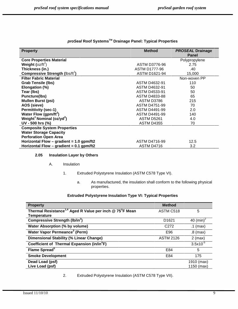
proSeal Roof SystemsTM Drainage Panel: Typical Properties
Property Method PROSEAL DrainagePanel
Core Properties MaterialWeight (oz/ft2)Thickness (in.)Compressive Strength (lbs/ft2)
ASTM D3776-96ASTM D1777-96
ASTM D1621-94
Polypropylene2.75.40
15,000Filter Fabric MaterialGrab Tensile (lbs)Elongation (%)Tear (lbs)Puncture(lbs)Mullen Burst (psi)AOS (sieve)Permittivity (sec-1)Water Flow (gpm/ft2)Weight1 Nominal (oz/yd2)UV - 500 hrs (%)
ASTM D4632-91ASTM D4632-91ASTM D4533-91ASTM D4833-88
ASTM D3786ASTM D4751-99ASTM D4491-99ASTM D4491-99
ASTM D5261ASTM D4355
Non-woven PP110505065
215702.01404.070
Composite System PropertiesWater Storage CapacityPerforation Open AreaHorizontal Flow – gradient = 1.0 gpm/ft2Horizontal Flow – gradient = 0.1 gpm/ft2
ASTM D4716-99ASTM D4716
12.53.2
2.05 Insulation Layer by Others
A. Insulation
1. Extruded Polystyrene Insulation (ASTM C578 Type VI).
a. As manufactured, the insulation shall conform to the following physicalproperties.
Extruded Polystyrene Insulation Type VI: Typical Properties
Property MethodThermal Resistance1,4 Aged R Value per inch @ 75oF MeanTemperature
ASTM C518 5
Compressive Strength (lb/in2) D1621 40 (min)2
Water Absorption (% by volume) C272 .1 (max)Water Vapor Permeance3 (Perm) E96 .8 (max)Dimensional Stability (% Linear Change) ASTM 2126 2 (max)Coefficient of Thermal Expansion (in/inoF) 3.5x10⁻⁵
Flame Spread5 E84 5Smoke Development E84 175Dead Load (psf)Live Load (psf)
1910 (max)1150 (max)
2. Extruded Polystyrene Insulation (ASTM C578 Type VII).

proSeal roof system specifications manual proSeal garden roof system
Issued 11/10/10 10
a. As manufactured, the insulation shall conform to the following physicalproperties.
Extruded Polystyrene Insulation Type VII: Typical Properties
Property MethodThermal Resistance1,4 Aged R Value per inch @ 75oF MeanTemperature
ASTM C518 5
Compressive Strength (lb/in2) D1621 60 (min)2
Water Absorption (% by volume) C272 .1 (max)Water Vapor Permeance3 (Perm) E96 .8 (max)Dimensional Stability (% Linear Change) ASTM 2126 2 (max)Coefficient of Thermal Expansion (in/inoF) 3.5x10⁻⁵
Flame Spread5 E84 5Smoke Development E84 175Dead Load (psf)Live Load (psf)
2880 (max)1720 (max)
3. Extruded Polystyrene Insulation (ASTM C578 Type V).As manufactured, the insulation shall conform to the following physical properties.
Extruded Polystyrene Insulation Type V: Typical Properties
Property MethodThermal Resistance1,4 Aged R Value per inch @ 75oF MeanTemperature
ASTM C518 5
Compressive Strength (lb/in2) D1621 60 (min)2
Water Absorption (% by volume) C272 .1 (max)Water Vapor Permeance3 (Perm) E96 .65 -.8 (max)Dimensional Stability (% Linear Change) ASTM 2126 2 (max)Coefficient of Thermal Expansion (in/inoF) 3.5x10⁻⁵
Flame Spread5 E84 5Smoke Development E84 165Dead Load (psf)Live Load (psf)
4800 (max)2880 (max)
NOTES:1. Values are consistent with the criteria of ASTM C578 and the requirements of the
FTC R-value rule (16 CFR Part 460).
2. Vertical compressive strength is measured at 5% deformation or at yield,whichever occurs first. Since the extruded insulations are viscoelastic materials,adequate design safety factors should be used to prevent long term creep. Forstatic loads, 3-1 is suggested.For dynamic loads, 5-1 is suggested.
3. Water vapor permeance varies with product type and thickness. Values arebased on the desiccant method and they apply to insulation 1 in. or greater inthickness.
4. R means resistance to heat flow. R-values are expressed in °F•ft2•h/BTU.

proSeal roof system specifications manual proSeal garden roof system
Issued 11/10/10 11
5. This numerical flame spread rating is not intended to reflect hazards presentedby this or any material under actual fire conditions.
2.06 Related Materials by Others
A. Pavers & Pedestals
1. 2” precast concrete pavers specifically designed and manufactured for roofingapplications to withstand freeze/thaw cycles and wind uplift. Minimum weight of 25lb/ft.2. Compressive strength 8,500 psi. Density 155 lb/ft.3.
B. Ballast
1. Nominal 2½” (62 mm) in size, smooth, washed, clean, well rounded gravel, toASTM D448 #2, #1.
C. Miscellaneous Fasteners & Anchors
1. All fasteners shall be the same type as the metal being secured. In general, allfasteners, anchors, nails, and straps shall be of zinc or cadmium plated steel, orstainless steel. All fasteners and anchors shall have a minimum embedment of 1”and shall be approved for such use by the fastener manufacturer. Fasteners forattachment of metal to wood blocking should be angular ring shank nails with 1”minimum penetration. Fasteners for attachment of metal to masonry should beexpansion type fasteners. All fasteners shall meet Factory Mutual Standard 4470 forcorrosion resistance.
D. Divider
1. Precast concrete divider/curb specifically designed and manufactured for roofingapplications to withstand freeze/thaw cycles and wind uplift. Minimum height of 6”.Compressive strength 8,500 psi. Density 155 lb/ft.3.
2. Wood divider/curb should be treated for fire and rot resistance (wolmanized orosmose treated), #2 or better lumber. Minimum size 6” x 6”. All wood shall have amaximum moisture content of 19% by weight on a dry weight basis.
E. Wood Nailers
1. Wood nailers should be treated for fire and rot resistance (wolmanized or osmosetreated), #2 or better lumber. Creosote or asphaltic-treated lumber is not acceptable.
2. All wood shall have a maximum moisture content of 19% by weight on a dry weightbasis.
3.00 EXECUTION
3.01 General
A. The waterproofing contractor has inspected and found the substrate suitable for theinstallation of the proSeal C3 membrane system.
B. The waterproofing contactor should coordinate the installation so that each area is madewatertight at the end of the day.

proSeal roof system specifications manual proSeal garden roof system
Issued 11/10/10 12
3.02 Deck Preparation: The structural deck shall be structurally sound to provide support for the newwaterproof system.
A. New Construction
1. The Poured Structural, Lightweight Structural, or Precast, Pre-stressed ConcreteDeck shall be cured and dry to industry standards, and the surface shall besmooth, level, and free from moisture or frost. Sharp ridges or other projectionsabove the surface shall be removed before roofing. On precast, pre-stressedconcrete decks all joints shall be grouted. Applying a lightweight fill over theentire deck or a grout applied over the joints and feathering out to create asmooth transition must correct differentials in deck elevation of more than ¼”.
B. Re-roofing With Removal of Existing Roofing
1. General Criteria: All existing overburden, waterproofing, flashings, deterioratedwood blocking, and metal flashings shall be removed. Remove only that amountof waterproofing and flashing that can be made watertight with new materialsduring a one-day period or onset of inclement weather.
2. The deck surface shall be smooth, level, and free from moisture or frost. Sharpridges or other projections above the surface shall be removed beforewaterproofing. On precast, pre-stressed concrete decks all joints shall begrouted. Applying a lightweight fill over the entire deck or a grout applied over thejoints and feathering out to create a smooth transition must correct differentials indeck elevation of more than ¼”.
3.03 Substrate Preparation
A. A proper substrate shall be provided to receive the Loose Laid proSeal C3 Single-PlyMembrane with prefabricated flashings and other items to comprise a waterproofingsystem.
B. The waterproofing contractor shall inspect the substrate for defects, such as, excessivesurface roughness, contaminated surfaces, structurally unsound substrates, and anythingthat will adversely affect the quality of work.
C. The substrate shall be clean, smooth, dry, and free from flaws, sharp edges, loose andforeign material, oil, and grease. Waterproofing shall not start until all defects have beencorrected.
D. All surfaces to be waterproofed shall be free from water, ice, or snow.
3.04 Wood Nailers
A. Install continuous treated wood nailers at the perimeter of the entire waterproof area andaround projections and penetrations as specified on project drawings.
B. Nailers shall be anchored to resist a minimum force of 175 pounds per lineal foot in anydirection. Fastener spacing shall be a maximum of 3’ o.c. Fasteners shall be installedwithin 6” of each end. Spacing and fastener embedment shall conform to Factory MutualLoss Prevention Data Sheet 1-49.
proSeal roof system specifications manual proSeal garden roof system
Issued 11/10/10 13
C. Thickness shall be as required to match substrate or insulation height.
D. Any existing woodwork that is to be reused shall be firmly anchored in place (it shallresist a minimum force of 175 pounds per lineal foot in any direction) and free from rot.Only woodwork designated to be reused in detail drawings shall be left in place, all otherwoodwork shall be removed.
3.05 Water Stop Installation
A. proBond water stop is to be installed on structural decks (refer to Section 3.03).
B. Install water stop in accordance with the layout shown on the design drawings/approvedshop drawings. The water stop is to be installed in intervals across the length and widthof the deck surface (recommended maximum area is 3,000 sf) as well as at all transitionsto the perimeter, wall, curb, drain, stack or other protrusions.
3.06 Deck Separation Sheet Installation
A. The proSeal Separation Sheet, if required, shall be applied over the insulation substrate.Overlap separation sheets a minimum of 6”.
B. The separation sheet shall be protected from damage. If punctured or damaged anadditional piece shall be installed overlapping the underlying layer a minimum of 6” andsealed with proSeal Polyurethane Caulking.
C. The installation of a separation sheet is to be followed immediately by the installation ofproSeal membrane.
D. Install only as much separation sheet as can be covered by the proSeal membrane inone day.
3.07 Waterproofing Membrane Installation
A. The surface of the leveling layer shall be inspected prior to installation of the proSealmembrane. Repair and/or replace the leveling layer as required to ensure completecoverage of the deck between water stop.
B. proSeal membrane is to be installed according to proSeal Roof SystemsTM
specifications and details.
C. Over the properly prepared leveling layer unroll the proSeal membrane and draw tightwithout folds or wrinkles. Adjacent sheets shall be overlapped 3”. All sheets shall beapplied in the same manner lapping all sheets as specified.
D. Roll out the membrane in a direction determined by deck configuration and workingconditions. If shop drawings have been prepared for specific projects, install membranein accordance with drawings. Install membrane in a parallel course to the substrate(where applicable) and position the membrane (where possible) to minimize the flow ofwater against the seam.
3.08 Hot-air Welding Seams & Overlaps
A. General.
1. All surfaces areas to be welded are to be dry, clean and free of dirt, debris andadhesives according to proSeal Roof SystemsTM recommendations.

proSeal roof system specifications manual proSeal garden roof system
Issued 11/10/10 14
2. Adjacent sheets shall be welded in accordance with the manufacturer’s writteninstructions. All side and end laps shall be hot-air welded.
Note: Overlap is to be 5½” when the plates are installed in the overlap.
3. Welding equipment shall be provided by or approved by proSeal RoofSystemsTM.
4. Prior to commencement of welding process, determine correct temperaturesetting and welding speed of equipment using test samples.
B. Hand Welding: Perform hand welding in the following stages.
Note: proSeal Roof SystemsTM requires 220V automatic welders be used as much aspossible. We encourage hand welding kept to detail work and smaller seams.
1. Warm up hot-air welding equipment as recommended by the equipmentmanufacturer.
2. All mechanics that intend to use the equipment shall have successfullycompleted a course of instruction provided by RPW Associates prior to welding.
3. Position the membrane in place with specified seam joint overlaps.
4. Pre-weld back edge, with narrow continuous weld, approximately ½” wide toprevent heat loss during the final welding stage. The pre-weld shall bepositioned, from the outside edge, the distance of the width of the nozzle used forthe welding application.
5. Finally, weld outside edge with a continuous seam of approximately 1” width.Insert the nozzle into the seam at a 45-degree angle. When the membranebegins to flow and the proper welding temperature is reached, position the handroller perpendicular to the nozzle and press adequately to achieve a continuoushomogeneous weld. Move the hot-air welder and roller in smooth continuousmotion along the seam. Welding seam ranges from 1’ to 2’ per minute. Forstraight laps use a 1½” wide nozzle. For corners and compound connections usea ¾” wide nozzle. Remove residue collected at nozzle with steel wire brush priorto start of new seam.
C. Automatic (Machine) Welding: Perform hand welding in the following stages.
Note: proSeal Roof SystemsTM automatic welding equipment will help to insure thatproper field seams are made.
1. Warm up hot-air welding equipment as recommended by the equipmentmanufacturer.
2. All mechanics that intend to use the equipment shall have successfullycompleted a course of instruction provided by RPW Associates prior to welding.
3. Position the membrane in place with specified seam joint overlaps.
4. Perform machine welding as per welding machine instructions. Continuouslyguide and supervise welding machine during entire welding process. Removemembrane residue collected at nozzle with steel wire brush at least every 100’and prior to start of a new seam. Welding speed ranges from 8’ to 10’ perminute. Local codes for electrical supply, grounding, over-current protection andother related items are to be observed. Typically automatic welding machinesrequire 218 to 230 volts at 30 to 40 amps.

proSeal roof system specifications manual proSeal garden roof system
Issued 11/10/10 15
The use of a portable generator (minimum output of 6500W) or direct wiring are therecommended power supplies.
D. Quality control of seams.
1. Visual evidence of proper welding is minor smoke development during thewelding process, shiny membrane surface and an uninterrupted bead ofthermally fused material from the underside of the top membrane.
2. The waterproofing contractor shall physically check all completed hot-air weldedseams after cooling for continuity of weld by using a seam probe. Any voids ordeficiencies in the membrane seaming are to be repaired by the end of the workperiod. Apply an additional layer of membrane extending 3”, in all directions,beyond the area to be repaired and hot-air weld using the hand weldingprocedures.
3. On-site physical evaluation of hot-air welded seams shall be made daily by thewaterproofing contractor at various seam locations or as directed by the ownerand/or the owner’s representative and/or the design professional and by RPWAssociates. 2” wide cross-sectional samples shall be taken three times a day(minimum) through completed seams. Correct welds that display failure fromshearing of the membrane prior to separation of the weld. The contractor, at noextra charge to the owner, shall patch each test cut. All field hot-air weldedseams shall be left exposed until reviewed and accepted by RPW Associates.Any voids or deficiencies in the membrane seaming are to be repaired by the endof the work period. Apply an additional layer of membrane extending 3”, in alldirections, beyond the area to be repaired and hot-air weld using the appropriate(hand or automatic) welding procedures.
4. A final probing of all seams and details shall be made at the conclusion of theproject. When automatic welding equipment is first started or any time that theequipment is cooled and restarted a minimum of two seam test cuts is required.These test cuts shall be dated, marked for location, and kept by the contractor incase future evaluation is needed.
3.10 Mechanical Fixation
A. Install proSeal Plate and Fastener at all transitional changes between the field(horizontal) and flashing (vertical) surfaces (e.g. parapets, walls, curbs, etc.).
B. Mechanically fasten the proSeal Plates 12” o.c., with proSeal Fasteners, penetrating intothe structural deck/substrate the appropriate depth.
C. Install proSeal Plate and Fastener at all penetrations (e.g. drains, vents pipes, stacks,etc.) on the waterproof surface spaced a maximum of 6” with a minimum of 4 fastenersper penetration.
D. Position the proSeal Plate approximately 1” from the edge of the flange (if applicable),penetrating the horizontal (field) membrane.Note:
1. Fasteners shall penetrate the underside of a steel deck a minimum of ¾” .
2. Fasteners shall penetrate the underside of a plywood deck a minimum of ¾”
3. Fasteners shall penetrate wood deck a minimum of ¾”

proSeal roof system specifications manual proSeal garden roof system
Issued 11/10/10 16
4. Fasteners shall penetrate poured structural, precast and pre-stressed concretedecks a minimum of 1”.
5. Consult RPW Associates for fastener penetration depths on all other structuraldecks.
3.11 Membrane Flashing
A. proSeal C3 flashing shall be installed concurrently with the proSeal C3 membrane asthe job progresses. No temporary flashing shall be allowed without the prior writtenapproval of the owner and/or the owner’s representative and/or the design professionaland proSeal Roof SystemsTM. Approval shall only be for specific locations on specificdates. All areas where water enters the new waterproof system shall be inspected andthe affected area shall be removed and replaced at no expense to the owner. proSeal C3membrane flashing shall be fully adhered to compatible, dry, smooth, and solventresistant surfaces.
B. 1700 Contact Adhesive for Flashing
1. Over the properly installed and prepared substrate surface, 1700 Adhesive shallbe applied using approved solvent resistant paint rollers. The adhesive shall beapplied to an approved substrate at a rate of approximately 120 sf per gallon.The adhesive shall be applied in smooth, even coatings with no voids, globs,puddles, or similar irregularities. Only an area that can be covered completely inthe same day's operations shall be coated with adhesive. The surface withadhesive coating shall be allowed to dry completely prior to installing themembrane.
a. Drying time increases with cooler temperatures and high humidityconditions. The contractor shall check with the proSeal Roof SystemsTM
technical representative prior to waterproof operations on such days.
b. The contractor shall count the amount of adhesive used per square, andthe number of buckets of adhesive used per area per day to verify thathe is conforming to the specified adhesive rate.
2. When the surface is dry, the proSeal C3 flashing membrane is cut to a workablelength and the underside shall be coated evenly with 1700 Adhesive at a rate of120 sf per gallon. NO BONDING ADHESIVE SHALL BE APPLIED IN LAPAREAS. While the adhesive is active (produces strings when touched with a dryfinger), the coated membrane shall be rolled carefully onto the previously coatedsubstrate to avoid wrinkles. Do not allow adhesive on the underside of theproSeal C3 membrane to dry completely. The amount of membrane that can becoated with adhesive before applying to substrate will be determined by ambienttemperature, humidity, and manpower. Adjacent sheets shall be overlapped aminimum of 4”. proSeal C3 flashings shall extend 5” onto the roofing membrane.The bonded sheet shall be pressed firmly into place with a hand roller.
3. No bonding adhesive shall be applied in lap areas that are to be welded toflashings or adjacent sheets. All sheets shall be applied in the same manner,lapping all sheets as required by welding techniques.
C. All flashings shall extend a minimum of 8” above roofing level unless previously acceptedby the owner and/or the owner’s representative and/or the design professional andproSeal Roof SystemsTM.
D. All flashing membranes shall be fully adhered to solvent-resistant substrates. All interiorand exterior corners and miters shall be cut and hot-air welded into place.

proSeal roof system specifications manual proSeal garden roof system
Issued 11/10/10 17
E. All flashings shall be hot-air welded at their joints and at their connections with thewaterproof membrane.
F. All flashing membranes shall be terminated according to Roof SystemsTM recommendeddetails. All mechanical fixations require fastening spaced 12” o.c. max. Grommettedmasonry fastener set in predrilled holes shall be used to secure flashings to masonry andconcrete surfaces.
3.12 Clad Metal Edge (24 GA. White Only)
Notes: All clad metal shall be proClad Metal.
All flashings shall be installed concurrently with the waterproof membrane as the jobprogresses.
A. proClad Metal Flashings shall be formed and installed per detail drawings and shallconform to the applicable requirements of the following:
1. Sheet Metal and Air Conditioning National Association Inc. (SMACNA – latestedition).
2. Factory Mutual Loss Prevention Data Sheet 1-49 (or latest edition).
3. National Roofing Contractors Association (NRCA – latest edition).
B. The fastening flange of the proClad Metal shall be a minimum of 2½” in width.Note: Hold back fasteners 1” from the outside edge of the proClad Metal so themembrane and/or flashing can be welded to the clad metal, completely covering allfasteners by 1” minimum.
C. proClad Metal Flashing shall be mechanically anchored into the approved substrate withapproved fasteners. Two rows of fasteners shall be installed 4” o.c. and staggered.
D. Metal shall be installed to provide adequate resistance to bending and allow for normalthermal expansion/contraction.
E. proClad Metal shall be spaced ¼”-½” apart. A 5” wide strip of flashing membrane shall behot-air welded over the center of the joint.
F. A 24-gauge (minimum) continuous metal cleat is required if proClad Metal fascia exceeds4” in width. The metal cleat is to be fastened 12” o.c. into the wood nailer or the masonrywall.
G. proClad Metal may be painted with exterior latex paint after roofing project is completed.Caution should be taken to prevent over spray of paint on roofing or building surfaces.
3.13 Waterproofing/Protection Layer Separation Sheet Installation
A. The proSeal Separation Sheet, if required, shall be applied over proSeal C3 membrane.Overlap separation sheets a minimum of 6”.
B. The separation sheet shall be protected from damage. If punctured or damaged anadditional piece shall be installed overlapping the underlying layer a minimum of 6” andsealed with proSeal Polyurethane Caulking.
C. The installation of a separation sheet is to be followed immediately by the installation ofproSeal HDPE Protection Layer.

proSeal roof system specifications manual proSeal garden roof system
Issued 11/10/10 18
D. Install only as much separation sheet as can be covered by the proSeal HDPEProtection Layer in one day.
3.14 Protection Layer Installation
A. Over the proper separation sheet and/or the waterproofing membrane unroll theproSeal HDPE Protection Sheet and draw tight without folds or wrinkles.
B. Adjacent sheets shall be overlapped 3” and hot-air welded. Overlaps shall be made withthe flow of water where possible. All sheets shall be applied in the same manner lappingall sheets as specified.
C. Install the HDPE Protection Layer on vertical surfaces 2” above the height of theoverburden as a minimum.
D. Intermittently secure the proSeal HDPE Protection Layer to the proSeal C3 membraneon all vertical surfaces with proSeal Foil Tape as per proSeal Roof SystemsTM
recommended details.
3.15 Insulation Installation
A. Extruded Polystyrene Insulation shall be installed according to the insulation manufacturer'scurrent published specifications for use with a Rooftop Garden System
B. Install Extruded Polystyrene Insulation directly over the protection layer. Install insulationin parallel courses, butted together in moderate contact without gaps, and staggered endjoints. Provide full support at ends. When multiple layers of insulation are specified thesubsequent layers shall be installed with joints offset from the underlying layer.
C. Extruded Polystyrene Insulation shall be neatly cut to fit around penetrations and projectionswithout gaps.
D. Install Tapered Extruded Polystyrene Insulation in accordance with the insulationmanufacturer's shop drawings.
E. Install Tapered Extruded Polystyrene Insulation around drains to create a drain sump.
F. Do not install more Extruded Polystyrene Insulation than can be covered with proSealSeparation Sheet, proSeal Drainage Panel and overburden by the end of the day.
3.16 Insulation/Drainage Separation Layer Installation
A. The proSeal Separation Sheet shall be applied over Extruded Polystyrene Insulation.Overlap separation sheets a minimum of 6”.
B. The separation sheet shall be protected from damage. If punctured or damaged anadditional piece shall be installed overlapping the underlying layer a minimum of 6” andsealed with proSeal Polyurethane Caulking
C. The installation of a separation sheet is to be followed immediately by the installation ofthe proSeal Drainage Panel.
D. Install only as much separation sheet as can be covered by the proSeal Drainage Paneland overburden in one day.

proSeal roof system specifications manual proSeal garden roof system
Issued 11/10/10 19
3.17 Drainage Panel Installation
Note: A 2% slope in the substrate is required. Contact RPW Associates, Inc. if the slope is lessthan 2%.
A. Install the proSeal Drainage Panel at the lowest point to create a shingling effect toensure sound drainage. The drainage panels must be shingled in the direction of thewater flow.
B. Install the drainage panel filter side up. The drainage panel may be adhered at 10’ intervalsusing two sided masking tape.
C. Overlap the flat tab.
D. Overlap the fabric onto the preceding panel and adhere the overlapped fabric with duct tapeto prevent overburden from entering the drainage panel during installation.
E. Inspect the fabric and repair any holes or tears with new filter fabric lapping the repair area by6” in all directions and seal with duct tape.
F. Around all protrusions cover all cut areas with extra piece of filter fabric lapping the cut areaby 6” in all directions and seal with duct tape.
G. Ensure any exposed core is covered with filter fabric.
H. Do not leave the drainage panel exposed to direct sunlight for prolonged periods. Theinstallation of the overburden should occur on the same day as the installation of the drainagepanel.
3.18 Precast Paver Installation
A. Prior to the installation of the pavers install a divider (as detailed) between the area toreceive the overburden and the pavers. The divider may be pressure treated wood(minimum 6” x 6”) or concrete divider (minimum 4” x 4”).
B. Install the divider on a 1” Extruded Polystyrene insulation spaced intermittently to allowfor the flow of water.
C. Install proSeal Separator Sheet 6” onto the drainage panel and up the vertical surface ofthe divider to retain the overburden.
D. Install proSeal Separator Sheet 6” onto the drainage panel and up the vertical surfacecovering the proSeal HDPE Protection Sheet.
E. Install pavers a minimum of 24” from all vertical surfaces (e.g. perimeter, walls, dividersetc.) and all penetrations (e.g. drains, vent pipes etc.).
F. Install pavers in parallel rows. Cut and fit all pavers neatly at all vertical surfaces andpenetrations.
G. Pavers are to be installed on pedestals and fully supported at all edges. Shim and adjustall pavers/pedestals as required to provide a level surface.

proSeal roof system specifications manual proSeal garden roof system
Issued 11/10/10 20
3.19 Ballast Installation
A. Prior to the installation of the ballast install a divider (as detailed) between the area toreceive the overburden and the ballast. The divider may be pressure treated wood(minimum 6” x 6”) or concrete divider (minimum 4” x 4”).
B. Install the divider on a 1” Extruded Polystyrene insulation spaced intermittently to allowfor the flow of water.
C. Install proSeal Separator Sheet 6” onto the drainage panel and up the vertical surface ofthe divider to retain the overburden.
D. Install proSeal Separator Sheet 6” onto the drainage panel and up the vertical surfacecovering the proSeal HDPE Protection Sheet.
E. Install ballast a minimum of 24” from all vertical surfaces (e.g. perimeter, walls, dividersetc.) and all penetrations (e.g. drains, vent pipes etc.) at a rate of 60 lb/sf.
3.20 Miscellaneous Metal Flashings
A. Metal, other than that supplied by RPW Associates, is not covered under the proSealRoof SystemsTM warranty.
B. Metal shall be installed to provide adequate resistance to bending and allow for normalthermal expansion/contraction.
C. All fabrication practices and installation procedures shall conform to the applicablerequirements of the following, unless otherwise specified and/or detailed:
1. Sheet Metal and Air Conditioning National Association Inc. (SMACNA – latestedition).
2. Factory Mutual Loss Prevention Data Sheet 1-49 (or latest edition).
3. National Roofing Contractors Association (NRCA – latest edition).
3.21 Temporary Cutoff
A. All flashings shall be installed concurrently with the waterproof membrane in order tomaintain a watertight condition as the work progresses. When a break in the day'swork occurs in the central area of a waterproof, a temporary water stop shall beconstructed to provide a 100% watertight seal. When work on the new system issuspended, the stagger of the insulation joints shall be maintained by installing partialfillers. The new membrane shall be carried into the water stop. The water stop shall besealed to the deck and/or substrate so that water will not be allowed to travel under thenew or existing waterproofing. The outside edge of the membrane shall be sealed in acontinuous heavy bead of mastic Water Stop. When work resumes, the contaminatedmembrane shall be cut out. All water stop, contaminated membrane, insulation fillers,etc. shall be removed from the work area and disposed of off-site. None of thesematerials shall be used in the new work.
B. If inclement weather occurs while a temporary water stop is in place, the contractor shallprovide the necessary labor to monitor the situation and maintain a watertight condition.
C. If any water is allowed to enter under the newly completed waterproofing, the affectedarea shall be removed and replaced at the contractor's expense.
proSeal roof system specifications manual proSeal garden roof system
Issued 11/10/10 21
3.22 Completion
A. Prior to leaving the site, the owner/project manager and contractor shall review the work.All defects noted, non-compliances with the specifications, and the recommendations ofproSeal Roof SystemsTM shall be itemized in a punch list. The Contractor mustimmediately correct these items to meet the satisfaction of the owner/project manager.
B. All warranties, as required in section 1.00 of this specification, shall be submitted to RPWAssociates, Inc. for approval. All materials purchased from RPW Associates, Inc. for theproSeal Roof SystemsTM shall be paid in full prior to the issuance of any warranty.
DISCLAIMER
RPW Associates, Inc. has attempted to obtain information from the manufacturers of other products often used inconjunction with proSeal Roof SystemsTM products with respect to the characteristics of such products, as well astheir compatibility with those of proSeal Roof SystemsTM. In as much as these other products, as supplied in thefield, are subject to possible variation in their production, and in as much as their specifications and performancecharacteristics are subject to change without notification by the manufacturers, RPW Associates, Inc. expresslyexcludes from its warranty any responsibility for the performance or quality of the products of others used inconjunction with proSeal Roof SystemsTM products.