Embed Size (px)
Citation preview

Dr. David V. JamesP802.17 Working Group Member 13
Proposals forResilient Ring Protocols
1. Overview
This is a very rough draft proposal for a Resilient Packet Ring Access Protocol (RRP). This documentrepresents a consensus position of multiple participants, but has not yet been reviewed by a wide audience.Therefore, this document does not necessarily represent the consensus of the P802.17 Working Group.
1.1 Document scope and purpose
The following scope and purpose statements, as stated in the project PAR, apply to this standards activity.
Scope: Define a Resilient Packet Ring Access Protocol for use in Local, Metropolitan, and WideArea Networks, along with appropriate Physical Layer specifications for transfer of data packetsat rates scalable to multiple gigabits per second.
Purpose: The standard will define a very high-speed network protocol that is optimized forpacket transmission in resilient ring topologies. Current standards are either optimized for TDMtransport, or optimized for mesh topologies. There is no high-speed (greater than 1 billion bitsper second) networking standard in existence, which is optimized for packet transmission in ringtopologies.

DVJ Proposal March 5, 2001P802.17 PROPOSED CONTRIBUTION TO
Dr. David V. James14 P802.17 Working Group Member
1.2 Objectives
1.2.1 Objectives summary
The primary objective of RRP is to provide enhanced services for the transmission of Ethernet packets overa ring-based interconnect topology. Secondary objectives include the following:
1) Flexible. Flexibility features, which increases the usefulness of the standard, includes the following:.a) Partitions. RRP is easily partitioned to support distinct service level agreements (SLAs).b) Synchronized. Nodes can be accurately synchronized to standard global timers.c) Classified. Multiple classes of transport services are provided, including:
i) Synchronous (low latency, voice and video)ii) Asynchronous (high-bandwidth, cost-effective)
d) Ordered. Ordered delivery is maintained within each packet flow.e) Extensible: The protocols can be readily extended, in standard or vendor-dependent ways:
i) Standard headers. Efficient standardized extended header are provided.ii) Dependent headers. Self-administered vendor-dependent extended headers are provided.iii) Payload. Larger (but less than 18k-byte) packets are allowed.
2) Subclasses. Multiple asynchronous subclasses are available:a) Unfair. Latency insensitive high priority traffic, such as prioritized HTTP traffic.b) Fair. Latency insensitive lower priority traffic, such as management messages
i) Fairness with one source/classii) Fairness measured in bytes, over congested segment
c) Bulk. Latency insensitive opportunistic traffic, such as file transfers.3) Robust: The interconnect operates well in the presence of transient transmission errors:
a) Errors: The interconnect operates well in the presence of transient transmission errors:i) Checked. Error-checked header and extended headersii) Covered. Encapsulated Ethernet packet (including FCS)
b) Faults: The interconnect operates well in the presence of persistent of cable failures:i) Recovery. Fast topology-change recovery (under 50ms)ii) Resilient. Ring survives in presence of single-fiber failure
c) Plug-and-play: The interconnect operates well in the presence of cable topology changes:i) Changes. Nondisruptive insertion and deletion reduces the impact of on-line upgrades.ii) Topology. An arbitrary physical-cable topology is allowed
(only a ring subset of the physical topology is actively enabled).4) Scalable: The protocols should be scalable in multiple ways:
a) Distance: RRP is applicable between within-the-home and within-the-planet distances.b) Bandwidth: RRP is applicable to low-rate as well as multiple gigabit/second rate media.

March 5, 2001 DVJ ProposalRESILIENT RING PROTOCOL (RRP) P802.17
Dr. David V. JamesP802.17 Working Group Member 15
1.2.2 Objectives, requirements, and strategies
1.2.2.1 Compatible
Objective: Ethernet, ATM, and other protocol packets should be sent in an unmodified fashion.Requirement: Shall be capable of encapsulating Ethernet packets.Strategy: The 48-bit MAC addresses are encapsulated within 64-bit MAC addresses.
Standard and vendor-dependent headers enable identification of encapsulated formats.
Objective: Should be physical layer independent, allowing use any byte transfer media.Requirement: Shall be capable of using any byte and control transfer media.Strategy: Idle symbols are identified by a distinctive control symbol.
The previous and following idle symbols function as data-packet delimiters.
1.2.2.2 Quality of service
Objective: Should support eight or more quality-of-service levels.Requirement: Shall support guaranteed bandwidth&latency traffic, for telephone and video.Strategy: Separate bypass FIFOs for synchronous and asynchronous traffic.
Allow synchronous mid-packet preemption of asynchronous traffic.
Objective: Should support SLA (service level agreements) of bandwidth and quality of service.Requirement: Shall support SLA (service level agreements) of guaranteed bandwidth and latency.Strategies: Provide bandwidth guarantees for asynchronous and isochronous traffic.
Provide 1 ms latency guarantees for isochronous traffic.
Objective: Non-negotiated asynchronous bandwidth should be fairly allocated.Requirement: Non-negotiable asynchronous traffic shall have bounded delivery delays.Strategies: Round-robin processing of asynchronous traffic, with queue-size bounds.
Objective: Within each flow, all packets are transmitted and received in the same order.Requirement: On each ringlet, packets within each flow are transmitted and received in the same order.Strategies: On the same ringlet:
All synchronous packets are transmitted and received in the same order.All asynchronous packets are transmitted and received in the same order.
1.2.2.3 Wallclock synchronization
Objective: The clock-slave node timers can be accurately synchronized to the clock-master node.Requirement: The clock-slave node timers do not drift from the timer in the clock-master node.Strategies: Periodic time-reference packets are sent over duplex links, allowing attached nodes moni-
tor the arrival and departure times of these packets. The clock-slave nodes compensatetheir frequencies based on the differences between expected and observed times.
1.2.2.4 Scalable
Objective: The link should be applicable to within-the-home through within-the-planet applications.Requirement: The link shall be applicable to within-the-city through within-the-nation applications.Strategies: All timeouts are based on self-calibrating ring-circulation timers, so the protocols readily
adapt to changed in ring diameters. Synchronous traffic preempts asynchronous traffic, sothe length of asynchronous packets doesn’t effect synchronous packet latencies.

DVJ Proposal March 5, 2001P802.17 PROPOSED CONTRIBUTION TO
Dr. David V. James16 P802.17 Working Group Member
1.2.2.5 Resilient
Objective: The link should recover from topology changes within 50 ms.Requirement: The link shall recover from topology changes within several ringlet-circulation latencies.Strategies: Link changes involve a topology rediscovery, to handle all join/sever combinations.
Merging and dividing of two segments are optimized special cases.Miss-addressed packets are stripped within several ringlet-circulation times.
Objective: The link should operate over arbitrary cable topologies.Requirement: The link shall operate over daisy-chain or loop cable topologies.Strategies: A cable topology invokes topology exploration.
That exploration attempts to form a spanning tree by selectively disabling paths.The spanning-tree protocols detect and enables (rather than disables) a loop topology.
Objective: The location of failed or marginal links should be easily identifiable.Requirement: The location of failed links should be easily identifiable.Strategies: Data CRC checks are performed on a hop-by-hop basis.
Bad-CRC packets are distinctively marked, to avoid incrementing spurious error counts.Miss-addressed packets are aged and quickly discarded on their second ringlet circulation.
1.2.2.6 Efficient
Objective: The unicast destination or final multicast destination strips the returning packet.Requirement: The unicast destination or the multicast destination strips the returning packet.Strategies: The unicast packets are stripped based when they reach their destination.
The multicast packets are stripped based when they return to their source.
Objective: Packets should be transmitted in the most-optimal direction.Requirement: Packets shall be allowed to be sent on the more optimal counter-rotating ringlet.Strategies: Allow a time-stamped acknowledge indications to be returned.
The transmitter has the option of changing ringlets, based on acknowledge information.
1.3 RRP topologies
1.3.1 Ring topologies
RRP is targeted for cable-ring topologies and maximizes bandwidth capabilities through the use of full-duplex cabling, as illustrated in figure 1. The full-duplex cable infrastructure normally allows concurrenttransmissions on the clockwise and counter-clockwise rings, as illustrated in the left of figure 1. After asingle link failure, communication continues (but at a reduced rate) over the remaining ring, as illustrated inthe center figure 1. After a duplex cable failure, communication continues (but at a further reduced rate)over the daisy-chained connection, as illustrated in the right of figure 1.
Higher performance nodes are expected to have two attachments (an attachment is a location where packetscan be inserted or extracted). This allows packets to be sent in their preferred direction, or interleaved andsent over both rings. On the average, assuming randomly-distributed traffic and preferred direction
Figure 1—Ring topologies
damaged loopclosed loop severed loop

March 5, 2001 DVJ ProposalRESILIENT RING PROTOCOL (RRP) P802.17
Dr. David V. JamesP802.17 Working Group Member 17
prediction, the average path lengths can be reduced by nearly a factor of four (when compared to an open-loop topology). Bandwidth improvements of 2.5 are more typical, due to lowed efficiencies of synchronoustraffic, which circumscribes the ring and can therefore not benefit from traveling in the shortest direction.
Similar performance enhancing techniques have also been used on serial-copper SSA, serial-fiber FDDI1
(Fiber Distributed Data Interface”), and parallel-copper SCX interconnects2.
1.3.2 Hub topologies
An RRP topology can include larger multiported nodes, called hubs, as illustrated in figure 1. An N-portedhub can be used to expand the number of lower-cost single-ported nodes, as illustrated in the left of figure 1.Alternatively, hubs can support redundant fault tolerant connections, as illustrated in the right of figure 1.
1.3.3 Root nodes
Each ringlet has a distinctive node, called the root, as illustrated by the black-shaded nodes of figure 1. Theroot node is selected when the ring is initialized and has several responsibilities, listed below:
1) Timing. The root provides information to synchronize wallclock timers on other attached nodes.2) Packet aging. The root decrements nonzero time-to-live identifiers in passing through packets.3) Arbitration grants. The root processes arbitration requests to provide arbitration grants, where these
request and grant indications are transported within idle symbols.
The root node selection is constrained as listed below. The intent is to simplify 2-ported nodes by assigningthe root node (which is most effected by multiported initialization protocols) to a larger multiported node.
1) Primary. The root is selected from the set of n-ported nodes, where n is larger than 2.2) Secondary. In the absence of n-ported nodes, the root is selected from the set of 2-ported nodes.3) Incapable. The root is never selected from the set of 1-ported nodes.
1A set of communication protocols and a physical-layer interface developed with the intent of exceeding Ethernet data-transmissionbandwidths2The SCX Channel: A New, Supercomputer-Class System Interconnect, Steven Scott (Cray Research Inc.), Presented at the HotInterconnects III (IEEE Computer Society), August 10-12, 1995
Figure 2—Ring topologies
expansion connections redundant connections

DVJ Proposal March 5, 2001P802.17 PROPOSED CONTRIBUTION TO
Dr. David V. James18 P802.17 Working Group Member
1.4 Node data paths
1.4.1 Adaptable link routing
Within a simple 2-ported node, the data-paths are expected to flow through four multiplexers, whosecontrols are set during each bus reset. These multiplexers allow the node to utilize both ports (the normalcondition), or to bypass a defective/redundant left or right port, as illustrated in figure 3
This concept of an electronically-switched router is not new; a similar capability is provided by nodesattached to Serial Bus. Although Serial Bus supports N-port attachments, a 2-port design is sufficient tosupport the common topologies and simplifies the hardware design.
1.4.2 Simplified attach-point routing
A node’s attach point has multiple queues in each attach component, as described in 5.1. To simplify thisoverview discussion, only a few of these queues and their simplified behaviors is described. Each attachpoint has a receive interface, a transmit interface, and a bypass buffer for resolving concurrentreception/transmission conflicts, as illustrated in frame-1 of figure 4.
The simplified packet-transmission protocols are described below:
1) Setup. An outbound packet is readied for transmission. A send buffer (not illustrated) may benecessary for the packet to be transmitted at the (possibly faster) speed of the link.
2) Transmit. The send packet is transmitted, as illustrated in frame-2 of figure 4.During the transmission interval, incoming traffic is saved in the bypass buffer.
3) Receive. Packet are stripped based on their destinationMacAddress or sourceMacAddress, asfollows:
4) Recover. Incoming idle symbols are discarded, allowing the bypass-buffer symbols to be emptied.
Figure 3—Selectable data paths
Figure 4—Attach point routing
attachment0
attachment1
(1)application logic
bypass
receive transmit
(2) application logic
bypass
receive transmit
(3)application logic
bypass
receive transmit
(4) application logic
bypass
receive transmit

March 5, 2001 DVJ ProposalRESILIENT RING PROTOCOL (RRP) P802.17
Dr. David V. JamesP802.17 Working Group Member 19
1.5 Arbitration protocols
On traditional backplane buses, arbitration protocols are used to resolve conflicts and schedule packettransmissions. To avoid transmission conflicts, arbitration protocols are invoked before every packettransmission. The arbitration protocols may invoke prioritized and/or fair arbitration protocols to determinewhich packets can be sent.
In the networking environment, the overhead of invoking arbitration protocols before each packettransmission is no longer acceptable. Transmission conflicts are more efficiently resolved by transmittingduring inter-packet gaps, buffering conflicting arrivals in bypass FIFO storage, and repeating the bufferedpacket when packet transmissions cease. Arbitration protocols are still needed to allocate bandwidth, so thatthe node’s service level agreements (SLA) can be met, but are only invoked when heavy congestionconditions necessitate their use. A more efficient opportunistic transmission protocol is used under lightloading conditions, to maximize bandwidth utilization under typical usage conditions.
1.5.1 Traffic classes
RRP supports three types of delivery services, as illustrated in figure 5 and listed below. Each node isrequired to police its stream and unfair traffic to avoid exceeding its prenegotiated limits.
1) Stream (negotiated synchronous): Prenegotiated low-latency bandwidth.This service is expected to be used for transmission of streaming audio and/or video traffic.
2) Unfair (negotiated asynchronous): Prenegotiated higher-latency bandwidth.This service is expected to be used for transmission of contracted nonstreaming traffic.
3) Fair (fair asynchronous): Fairly assigned residual asynchronous bandwidth.This service is expected to be used for transmission of noncontracted traffic.
Figure 5—Attach point routing
stream
unfairh
igh
er
fair
DVJ Proposal March 5, 2001P802.17 PROPOSED CONTRIBUTION TO
Dr. David V. James20 P802.17 Working Group Member
1.5.2 Arbitration signals
The key element in the design of the arbitration protocols is the low-latency transmission of arbitration-related information within idle symbols, including the following:
1) Priority. For congested prioritized traffic, unfair arbitration involves the following:
a) Stream. Assertion of request-4/grant-4 values inhibits unfair & fair transmissions.
b) Unfair. Assertion of request-3/grant-3 values inhibits fair transmissions.
2) Fairness. For congested non-prioritized traffic, fair arbitration involves the following:
a) Requests. Assertion of request-1/request-2 indications activates round-robin transmissions.
b) Grants. Observance of grant-A/grant-B indications enables selective fair transmissions.
The arbitration indications flow in the reverse direction, with respect to the data-packet flows, starting fromnodes currently requesting their share of the bus bandwidth. The reverse-flow direction allows inactivenodes to delay forwarding of arbitration indications while filling of their bypass FIFO generates idles; nodeswhich cannot generate idles quickly forward arbitration indications to throttle upstream nodes.
The arbitration indications are level-sensitive signals, rather than tokens or edge-sensitive values, makingthe protocols robust. Most importantly, from a simplicity perspective, these idle-transported values can befreely inserted and deleted (without effect) when passing through elasticity buffers.
1.5.3 Arbitration signal flow
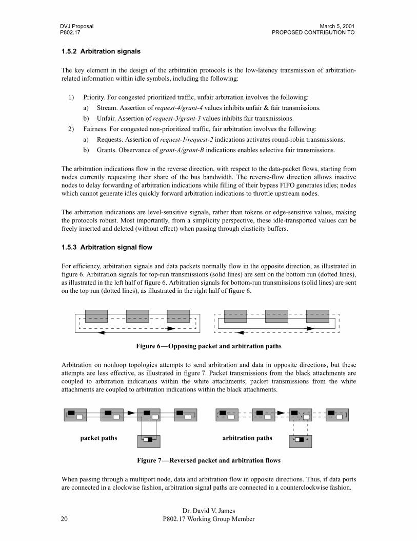
For efficiency, arbitration signals and data packets normally flow in the opposite direction, as illustrated infigure 6. Arbitration signals for top-run transmissions (solid lines) are sent on the bottom run (dotted lines),as illustrated in the left half of figure 6. Arbitration signals for bottom-run transmissions (solid lines) are senton the top run (dotted lines), as illustrated in the right half of figure 6.
Arbitration on nonloop topologies attempts to send arbitration and data in opposite directions, but theseattempts are less effective, as illustrated in figure 7. Packet transmissions from the black attachments arecoupled to arbitration indications within the white attachments; packet transmissions from the whiteattachments are coupled to arbitration indications within the black attachments.
When passing through a multiport node, data and arbitration flow in opposite directions. Thus, if data portsare connected in a clockwise fashion, arbitration signal paths are connected in a counterclockwise fashion.
Figure 6—Opposing packet and arbitration paths
Figure 7—Reversed packet and arbitration flows
packet paths arbitration paths

March 5, 2001 DVJ ProposalRESILIENT RING PROTOCOL (RRP) P802.17
Dr. David V. JamesP802.17 Working Group Member 21
1.5.4 Arbitration concepts
For simplicity, ringlet arbitration is introduced in the context of a damaged ringlet (see 1.3), where only oneof the ringlets is logically enabled, as illustrated in frame-1 of figure 8. Within this frame, the enabled anddisabled ringlets are drawn with solid and dotted lines respectively. Since arbitration protocols are uninflu-enced by the disabled ringlet, the dotted disabled ringlet is removed from the illustrations, as illustrated inframe-2 of figure 8.
Arbitration signaling involves encoding state indications within the arbs field inside idle symbols. Thecoding of the arbs field supports the sampling of request indications on pass-1 and the distribution of grantindications on pass-2. Separate lines are used to illustrate the flow of logically distinct pass-1 and pass-2information, as illustrated in frame-3 of figure 8, even though this information flows over only one link.
Wide shaded-gray lines illustrate the flow of asserted pass-1 request and pass-2 grant information. One node(called the root) has enabled arbitration-processing components, shaded white and black. The pass-1 rootprocessing initializes the pass-1 indication to a deasserted value. An intervening node can assert a pass-1request-0 indication, as illustrated in frame-4 of figure 8, which eventually flows to the root.
That root node is responsible for converting the arbitration request into an arbitration-grant indication, asillustrated in frame-5 of figure 8. An asserted grant indication has the effect of inhibiting packet-sendoperations on less congested nodes.
In this and the following discussions, arbitration is described in an unusual worst-case condition, for thepurpose of simplifying the illustrations and affiliated discussions. In reality, arbitration is typically a moretransient event; the request indications are often deasserted before grant indications are returned, asillustrated in frame-6 of figure 8.
Figure 8—Arbitration illustrations
(1) (2)
(3) (4)request1
node-W node-X node-Y node-Z
(5)request0
grant-A
node-W node-X node-Y node-Z
(6)
grant-A
node-W node-X node-Y node-Z

DVJ Proposal March 5, 2001P802.17 PROPOSED CONTRIBUTION TO
Dr. David V. James22 P802.17 Working Group Member
1.5.5 Prioritized arbitration
Prioritized arbitration involves the assertion of priority-4 or priority-3 requests, for stream and unfair trafficrespectively. The arbitrating node-Y asserts a request-4/grant-4 indication, inhibiting transmissions fromadjacent nodes, as illustrated in frame-1 of figure 9. At the root, the incoming request-4 is converted to agrant-4 and the incoming grant-4 is ignored, as illustrated in frame-2 of figure 9. The grant-4 indicationeventually propagates through the ringlet, as illustrated in frame-3 of figure 9.
Another node-X attachment may assert a request-3 indiction, which propagates to the request-4 generatingnode, as illustrated in frame-4 of figure 9. When node-Y is satisfied, it propagates the incoming request-3,rather than asserting the request-4 indication, as illustrated in frame-5 of figure 9. The closer-to-the-rootnode-W and node-X attachments are the first to observe the lowered priority level, as illustrated in frame-6of figure 9. The lowered priority indication circulates quickly to the remaining nodes, as illustrated inframe-7 of figure 9.
Deassertion of request-3 indication has no effect on other nodes while the deassertion propagates to the root,as illustrated in frame-8 of figure 9. The root then deasserts its grant-3 indication, as illustrated in frame-9 offigure 9. That deassertion quickly propagates around the ringlet, allowing nodes to arbitrate in anopportunistic fashion, as illustrated in frame-10 of figure 9.
Figure 9—Prioritized arbitration
(1)request-4
node-W node-X node-Y node-Z
grant-4
(2)request-4
grant-4
node-W node-X node-Y node-Z
grant-4
(3)request-4
grant-4
node-W node-X node-Y node-Z
(4)request-4
grant-4
node-W node-X node-Y node-Z
request-3
(5)
grant-4
node-W node-X node-Y node-Z
request-3(6)
grant-4
node-W node-X node-Y node-Z
grant-3
request-3
(7)
grant-3
node-W node-X node-Y node-Z
request-3(8)
node-W node-X node-Y node-Z
grant-3
request-3
(9)
grant-3
node-W node-X node-Y node-Z
(10)
node-W node-X node-Y node-Z
March 5, 2001 DVJ ProposalRESILIENT RING PROTOCOL (RRP) P802.17
Dr. David V. JamesP802.17 Working Group Member 23
1.5.6 Fairness arbitration
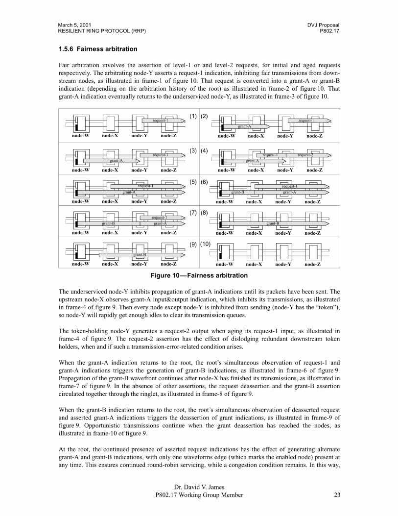
Fair arbitration involves the assertion of level-1 or and level-2 requests, for initial and aged requestsrespectively. The arbitrating node-Y asserts a request-1 indication, inhibiting fair transmissions from down-stream nodes, as illustrated in frame-1 of figure 10. That request is converted into a grant-A or grant-Bindication (depending on the arbitration history of the root) as illustrated in frame-2 of figure 10. Thatgrant-A indication eventually returns to the underserviced node-Y, as illustrated in frame-3 of figure 10.
The underserviced node-Y inhibits propagation of grant-A indications until its packets have been sent. Theupstream node-X observes grant-A input&output indication, which inhibits its transmissions, as illustratedin frame-4 of figure 9. Then every node except node-Y is inhibited from sending (node-Y has the “token”),so node-Y will rapidly get enough idles to clear its transmission queues.
The token-holding node-Y generates a request-2 output when aging its request-1 input, as illustrated inframe-4 of figure 9. The request-2 assertion has the effect of dislodging redundant downstream tokenholders, when and if such a transmission-error-related condition arises.
When the grant-A indication returns to the root, the root’s simultaneous observation of request-1 andgrant-A indications triggers the generation of grant-B indications, as illustrated in frame-6 of figure 9.Propagation of the grant-B wavefront continues after node-X has finished its transmissions, as illustrated inframe-7 of figure 9. In the absence of other assertions, the request deassertion and the grant-B assertioncirculated together through the ringlet, as illustrated in frame-8 of figure 9.
When the grant-B indication returns to the root, the root’s simultaneous observation of deasserted requestand asserted grant-A indications triggers the deassertion of grant indications, as illustrated in frame-9 offigure 9. Opportunistic transmissions continue when the grant deassertion has reached the nodes, asillustrated in frame-10 of figure 9.
At the root, the continued presence of asserted request indications has the effect of generating alternategrant-A and grant-B indications, with only one waveforms edge (which marks the enabled node) present atany time. This ensures continued round-robin servicing, while a congestion condition remains. In this way,
Figure 10—Fairness arbitration
(1)request-1
node-W node-X node-Y node-Z
(2)request-1
grant-A
node-W node-X node-Y node-Z
(3)request-1
grant-A
node-W node-X node-Y node-Z
(4)request-2
grant-A
node-W node-X node-Y node-Z
request-1
(5)
grant-A
node-W node-X node-Y node-Z
request-1(6)
grant-A
node-W node-X node-Y node-Z
grant-B
request-1
(7)
grant-B
node-W node-X node-Y node-Z
request-1
grant-A
(8)
node-W node-X node-Y node-Z
grant-B
(9)
grant-B
node-W node-X node-Y node-Z
(10)
node-W node-X node-Y node-Z

DVJ Proposal March 5, 2001P802.17 PROPOSED CONTRIBUTION TO
Dr. David V. James24 P802.17 Working Group Member
the transmission token (the grant-assertion waveforms) rotates continuously around the bus, with the stableperformance under high load characteristic of token-ring systems.

March 5, 2001 DVJ ProposalRESILIENT RING PROTOCOL (RRP) P802.17
Dr. David V. JamesP802.17 Working Group Member 25
2. References
The following documents are referenced by this standard:
ANSI X3.159–1989, Programming Language—C.3
ANSI/IEEE Std 1596-1992, Scalable Coherent Interface (SCI) (or IEC/ISO DIS 13961).4
3ANSI publications are available from the American National Standards Institute, Sales Department, 11 West 42nd St., 13th Floor, NewYork, NY 10036, 212-642-4900.4ANSI/IEEE publications are available from the Institute of Electrical and Electronics Engineers, Service Center, 445 Hoes Lane, P.O.Box 1331, Piscataway, NJ 08855-1331, USA.

DVJ Proposal March 5, 2001P802.17 PROPOSED CONTRIBUTION TO
Dr. David V. James26 P802.17 Working Group Member
3. Glossary and notation
3.1 Definitions
3.1.1 Conformance levels
Several keywords are used to differentiate between different levels of requirements and optionality, asfollows:
3.1.1.1 expected: A keyword used to describe the behavior of the hardware or software in the designmodels assumed by this S2I standard. Other hardware and software design models may also be implemented.
3.1.1.2 may: A keyword that indicates flexibility of choice with no implied preference.
3.1.1.3 shall: A keyword indicating a mandatory requirement. Designers are required to implement all suchmandatory requirements to ensure interoperability with other S2I standard conformant products.
3.1.1.4 should: A keyword indicating flexibility of choice with a strongly preferred alternative. Equivalentto the phrase “it is recommended.”
3.1.2 Definitions of RRP related terms
A large number of network and interconnect-related technical terms are used in this document. These termsare defined below:
3.1.2.1 aligned: A term which refers to the constraints placed on the address of the data; the address isconstrained to be a multiple of the data format size.
3.1.2.2 asynchronous packet: A component of asynchronous traffic.
3.1.2.3 asynchronous traffic: A collection of data packets with no prenegotiated transmission bandwidth,whose transmission can be preempted by higher priority asynchronous traffic.
3.1.2.4 big endian: A term used to describe the physical location of data-byte addresses within a multibyteregister. Within a big-endian register or register set, the data byte with the largest address is the least signifi-cant.
3.1.2.5 byte: An 8-bit entity. Within other standards, this is also called an octet.
3.1.2.6 doublet: A data format or data type that is 2 bytes in size.
3.1.2.7 hexlet: A data format or data type that is 16 bytes in size.
3.1.2.8 ignored; ign: A term used to describe the fields within unit-specific CSRs or command/statusentries whose zero or last-written values shall be ignored.
3.1.2.9 node: The entity associated with a particular set of (typically bus-dependent) control registeraddresses (including identification ROM and reset command registers). These registers are typically used toidentify the node and to initialize the state of unit-dependent registers. In normal operation each node can beaccessed independently (a control register update on one node has no effect on the control registers ofanother node).
March 5, 2001 DVJ ProposalRESILIENT RING PROTOCOL (RRP) P802.17
Dr. David V. JamesP802.17 Working Group Member 27
3.1.2.10 octlet: A data format or data type that is 8 bytes in size. Not to be confused with an octet, whichhas been commonly used to describe 8 bits of data. In this document, the term byte, rather than octet, is usedto describe 8 bits of data.
3.1.2.11 DRAM: An acronym for dynamic random-access memory.
3.1.2.12 quadlet: A data format or data type that is 4 bytes in size.
3.1.2.13 reserved; res or r: A term used to describe the fields within unit-specific CSRs. On a write, thereserved-field value shall be ignored. On a read, the reserved field value shall be zero.
3.1.2.14 ringlet: A term used to describe a enabled looping data path over which packets can be transferred.Within a given cable topology, there may be one circumscribing ringlet or two counter-rotating ringletsenabled.
3.1.2.15 SCI: See: Scalable Coherent Interface standard.
3.1.2.16 Scalable Coherent Interface (SCI) standard: Refers to IEEE Std 1596-1992 Scalable CoherentInterface [see clause 2], which provides computer-bus-like services using a collection of point-to-pointunidirectional links.
3.1.2.17 synchronous packet: A component of synchronous traffic.
3.1.2.18 synchronous traffic: Data traffic for which the transmission bandwidth is prenegotiated and thetransmission priority exceeds that of asynchronous traffic.
3.2 Acronyms
A large number of network and interconnect-related acronyms are used in this document; these are definedbelow:
RRP Resilient Packet Ring Access ProtocolSLA Service level agreement.
3.3 Field names
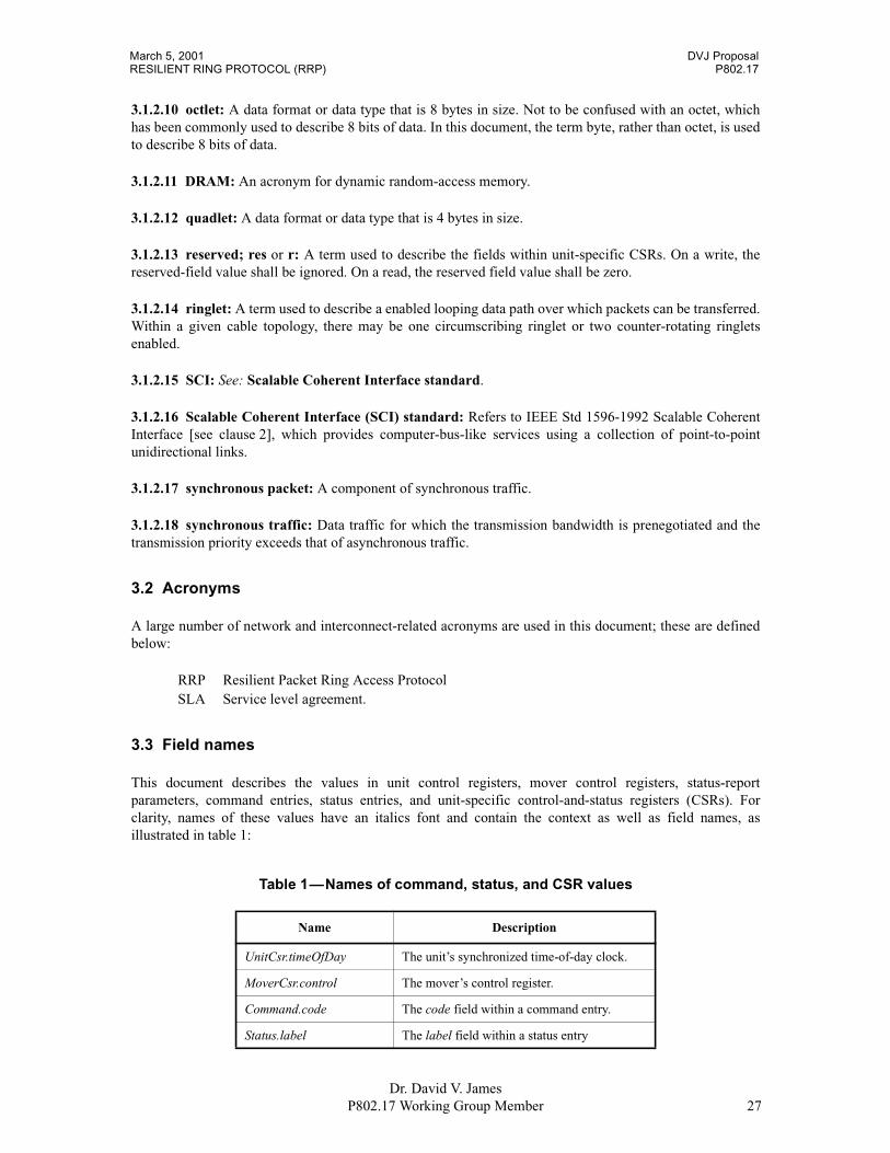
This document describes the values in unit control registers, mover control registers, status-reportparameters, command entries, status entries, and unit-specific control-and-status registers (CSRs). Forclarity, names of these values have an italics font and contain the context as well as field names, asillustrated in table 1:
Table 1—Names of command, status, and CSR values
Name Description
UnitCsr.timeOfDay The unit’s synchronized time-of-day clock.
MoverCsr.control The mover’s control register.
Command.code The code field within a command entry.
Status.label The label field within a status entry
DVJ Proposal March 5, 2001P802.17 PROPOSED CONTRIBUTION TO
Dr. David V. James28 P802.17 Working Group Member
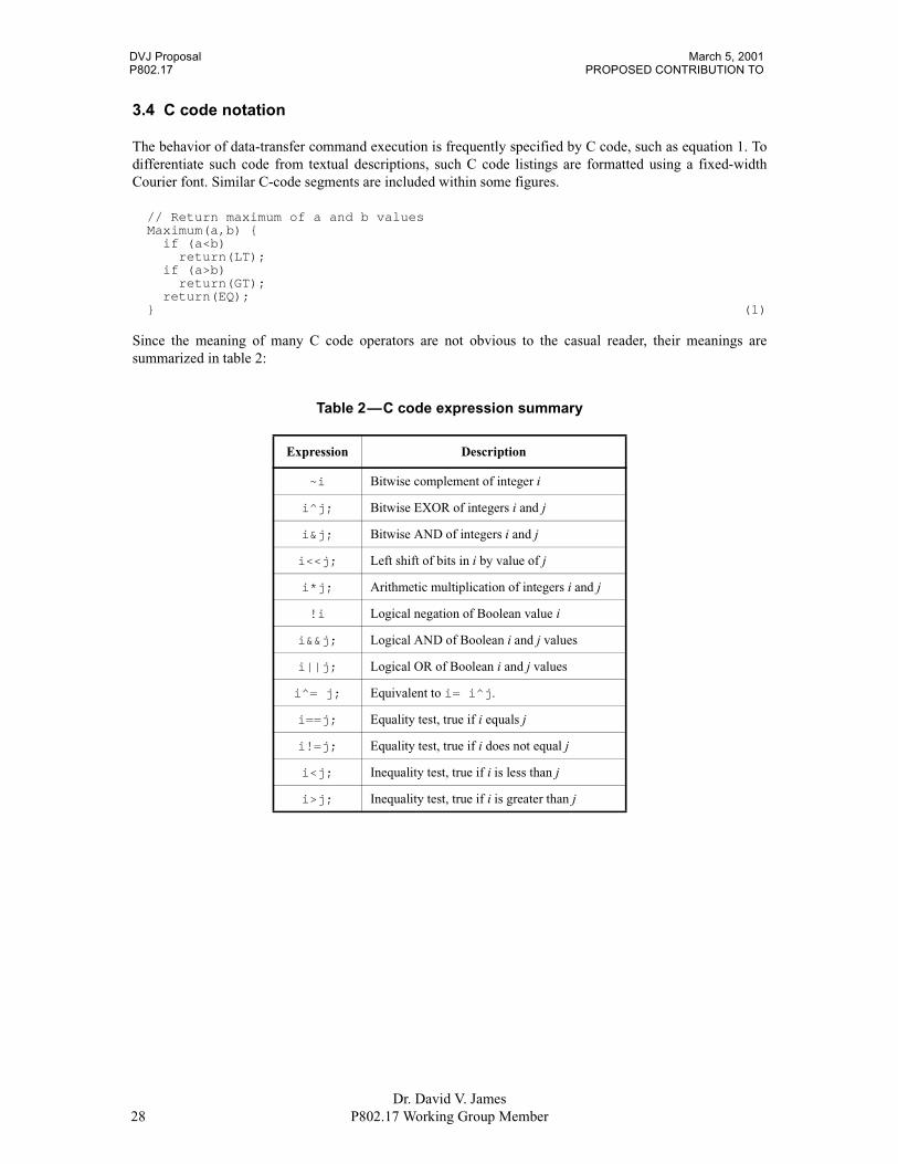
3.4 C code notation
The behavior of data-transfer command execution is frequently specified by C code, such as equation 1. Todifferentiate such code from textual descriptions, such C code listings are formatted using a fixed-widthCourier font. Similar C-code segments are included within some figures.
// Return maximum of a and b valuesMaximum(a,b) {
if (a<b)return(LT);
if (a>b)return(GT);
return(EQ);} (1)
Since the meaning of many C code operators are not obvious to the casual reader, their meanings aresummarized in table 2:
Table 2—C code expression summary
Expression Description
~i Bitwise complement of integer i
i^j; Bitwise EXOR of integers i and j
i&j; Bitwise AND of integers i and j
i<<j; Left shift of bits in i by value of j
i*j; Arithmetic multiplication of integers i and j
!i Logical negation of Boolean value i
i&&j; Logical AND of Boolean i and j values
i||j; Logical OR of Boolean i and j values
i^= j; Equivalent to i= i^j.
i==j; Equality test, true if i equals j
i!=j; Equality test, true if i does not equal j
i<j; Inequality test, true if i is less than j
i>j; Inequality test, true if i is greater than j
March 5, 2001 DVJ ProposalRESILIENT RING PROTOCOL (RRP) P802.17
Dr. David V. JamesP802.17 Working Group Member 29
3.5 Data formats
3.5.1 Numerical values
Decimal, hexadecimal, and binary numbers are used within this document. For clarity, decimal numbers aregenerally used to represent counts, hexadecimal numbers are used to represent addresses, and binarynumbers are used to describe bit patterns within binary fields.
Decimal numbers are represented in their usual 0, 1, 2, ... format. Hexadecimal numbers are represented by astring of one or more hexadecimal (0-9,A-F) digits followed by the subscript 16, except in C-code contexts,where they are written as 0x123EF2 etc. Binary numbers are represented by a string of one or more binary(0,1) digits, followed by the subscript 2. Thus the decimal number “26” may also be represented as “1A16”or “110102”.
3.5.2 Reserved registers and fields
The portions of the command-entry fields, status-entry fields, and unit-specific CSRs that are notimplemented have defined reserved values. This includes optional registers (when the option is not imple-mented) and reserved registers (which are required to be unimplemented), or unused portions of com-mand/status entries. The capabilities of reserved fields are exactly defined, to minimize conflicts betweencurrent implementations and future definitions.
For command-entry and status-entry fields, which are located in system-memory or transfer-buffer spaces,the reserved fields and bits shall be zero when the command is written.
Unused fields within register locations may be either reserved or ignored. The reserved option allows thesefield locations to be hardwired-to-zero, so that physical memory elements are not required. Alternatively, anignored field (a read of an ignored field returns the last-written value) allows registers to be specialaddresses within a general-purpose memory array.
DVJ Proposal March 5, 2001P802.17 PROPOSED CONTRIBUTION TO
Dr. David V. James30 P802.17 Working Group Member
3.6 Duplex ring reset
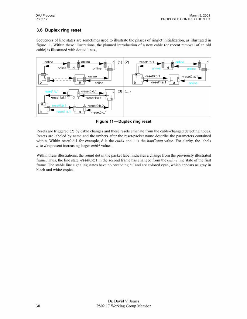
Sequences of line states are sometimes used to illustrate the phases of ringlet initialization, as illustrated infigure 11. Within these illustrations, the planned introduction of a new cable (or recent removal of an oldcable) is illustrated with dotted lines.,
Resets are triggered (2) by cable changes and these resets emanate from the cable-changed detecting nodes.Resets are labeled by name and the umbers after the reset-packet name describe the parameters containedwithin. Within reset0:d,1 for example, d is the eui64 and 1 is the hopCount value. For clarity, the labelsa-to-d represent increasing larger eui64 values.
Within these illustrations, the round dot in the packet label indicates a change from the previously illustratedframe. Thus, the line state •reset0:d,1 in the second frame has changed from the online line state of the firstframe. The stable line signaling states have no preceding ‘•’ and are colored cyan, which appears as gray inblack and white copies.
Figure 11—Duplex ring reset
(1)
online
online
online
online
online
b a
d online
c (2)
online
•reset0:a,1
•reset1:b,1
online
online
b a
d online
•reset0:b,1
•reset1:a,1
c
(3)
•reset0:c,1
•reset0:b,2
reset1:b,1
•reset1:d,1
•reset0:d,1
b a
d •reset1:c,1
c
reset0:b,1
reset1:a,1
(…)

March 5, 2001 DVJ ProposalRESILIENT RING PROTOCOL (RRP) P802.17
Dr. David V. JamesP802.17 Working Group Member 31
4. Packet and idle formats
4.1 Packet formats
4.1.1 Aligned payload formats
A packet consists of a basic header, zero or more optional extended header, and payload components. Thebasic header starts with 64-bit destinationMacAddress and sourceMacAddress components, as illustrated infigure 12.
The 64-bit destinationMacAddress field specifies the address of the destination node. The 64-bitsourceMacAddress field specifies the address of the source node. The 64-bit virtualLanId field specifies thelogical LAN over which the packet is to be transferred.
The 16-bit type1 field specifies the type of this extended header; the 8-bit size1 field specifies the length (inbytes) of the first extended header.
Within the next extended header, the 16-bit type2 field specifies the type of this extended header; the 8-bitsize2 field specifies the length (in bytes) of the second extended header. In a similar fashion, the 16-bit typeN
Figure 12—Packet format
ress izeP =0
loca
lm
ult
loca
lm
ult
des tinationM acA ddress
sourceM acA ddress
virtualLan ID
res crc32
crc32
size1
app lica tionD ependent
crc32
res
depends
basic header
extended header #1
payload
ttl
headerB ytes[s ize1 ]
type1
crc32
extended header #N
headerB ytes[s ize1 ]
typeP
(...other extended headers...)
s ize2type2

DVJ Proposal March 5, 2001P802.17 PROPOSED CONTRIBUTION TO
Dr. David V. James32 P802.17 Working Group Member
and 8-bit sizeN fields within the N’th extended header specified the type and size of the following extendedheader.
Within the final extended header, the 16-bit typeP field specifies the type packet payload that follows; the8-bit sizeP field shall be zero.
When the application data consists of an encapsulated Ethernet packet, the Ethernet-defined CRC-32 shallalso be included within the transported packet. The intent is to ensure end-to-end error-checking coverage.
4.1.2 Vendor-dependent extended headers
The format of packets and between packet idle symbols are based on a 64-bit word size, as illustrated infigure 13.
The 64-bit headerTypeID is an EUI-64 value that distinctively identifies the type of vendor-dependentheader.
The meaning of the following headerBytes[] are headerTypeID dependent.
The 16-bit typeM and 8-bit sizeM fields specify the type and size of the following extended header. The 32-bit crc32 field covers the preceding data bytes within the extended header.
4.1.3 Unaligned payload formats
To simplify high-speed processing, all data payloads shall be padded (as necessary) to the next 8-bytesboundary, as illustrated in figure 14.
Possible physical-layer-dependent identification of pad bytes include the following:
1) Code. A distinct control code (distinct from the 256 data codes) identifies a pad byte.2) Count. Information within the following idle symbol specifies the number of pad bytes.
Figure 13—Vendor-dependent extended header
Figure 14—Padded payloads
headerTypeID
crc32res
headerBytes[s izeN -4 ]
s izeMtypeM
data[8*n+1]
crc32
payload
FC S pad[0 ] pad[1 ] pad[2 ]
pad[3 ] pad[4 ] pad[5 ] pad[6 ]

March 5, 2001 DVJ ProposalRESILIENT RING PROTOCOL (RRP) P802.17
Dr. David V. JamesP802.17 Working Group Member 33
4.2 Idle symbols
4.2.1 Idle symbol format
The between packet 32-bit idle symbols provide packet framing and control information, as illustrated infigure 15.
The dependentA and dependentB fields are physical layer dependent (an example can be found in D.1.1).Although the size and format of these fields is physical-layer dependent, the following features are expectedto be supported:
1) Label. The inclusion of a leading control facilitates the following:a) Idle marker. The idle symbol can be distinguished from packetized data symbols.b) Frame marker. The starting character of the multicharacter symbol is easily identified.
2) Synchronize. The idle information is sufficient to synchronize scramble circuits.3) Protected. Common errors within the idle symbol are easily detected.
The 2-bit type field value distinctively identifies different types of signaling idles, as specified in table 3.
The c0 and cc bits are used to assert circulation control indications, as described in 6.1.
The 4-bit arbs field communicates asserted and returned ringlet priorities, as specified in 4.2.5.
The 8-bit checkSum field is the binary exclusive-OR of the previous two data bytes.
Figure 15—Idle format
Table 3—Idle symbol types
Value Name Description
0 IDLE_LO Asynchronous packet or idle follows
1 IDLE_LC Asynchronous fragment follows
2 IDLE_HI Synchronous packet or idle follows
3 — Reserved
type arbs dependentBc1c0dependentA

DVJ Proposal March 5, 2001P802.17 PROPOSED CONTRIBUTION TO
Dr. David V. James34 P802.17 Working Group Member
4.2.2 Idle symbol framing
Rather than providing an explicit start-of-frame indication, the start of a packet in cycle N is implied by thepresence of an idle in cycle N-1 and the presence of a data symbol in cycle N, as illustrated in figure 16.Similarly, the end of a packet in cycle M is indicated by the presence of a data symbol in cycle M and an idlesymbol in cycle M.
Idles can be inserted and deleted, for idle elasticity (see 6.5) and packet insertion/removal purposes. Idleinsertion and deletion protocols are restricted by the following simple rules:
1) Deletion. All but the first idle of a same-type idle-symbol sequence can be deleted.2) Insertion. Any idle symbol can be replicated any number of times.
4.2.3 Idle framed classification
The two basic idle symbol types, IDLE_LO and IDLE_HI, are used to identify following packetized data asasynchronous or synchronous in nature, as illustrated in figure 17. The packet classification determineswhether the packet is destined for the next node’s low-priority asyncFifo or high-priority syncFifo queuesrespectively.
Figure 16—Idle symbol framing
Figure 17—Idle-framed classification
id le packet id le packetid le id lepacket
increas ing tim e
id le
sta rt o f packe t
end o f packe t
de letab le id le start/end o f packet
LO packetA LO packetCLO X XpacketB
increas ing tim e
H I
asynchronous synchronous asynchronous

March 5, 2001 DVJ ProposalRESILIENT RING PROTOCOL (RRP) P802.17
Dr. David V. JamesP802.17 Working Group Member 35
4.2.4 Idle frame preemption
An asynchronous data stream followed a IDLE_LO symbol is used to preempt the asynchronous packet fora synchronous packet transmission, as illustrated in figure 18. The asynchronous transmission continuesafter the following IDLE_LC symbols.
4.2.5 Arbitration (arbs) field values
The 4-bit arbs field communicates sampled and asserted ringlet priorities, as specified in table 7. Within thistable, the next value is generated by scrubbing of the arbs input (see 6.1) and the level value is the priorityassociated with an outgoing arbs value (see 5.3). Within this context, level values of 0 through 4 representlowest through highest priorities respectively.
Figure 18—Idle frame preemption
Table 4—arbs values definitions
level Value Name request response Description
0 0 ARB_00 -none- -none- Deasserted arbitration
2 1 ARB_0A -none- grant-A Assertive fair-A grant
2 ARB_1A request-1 grant-A Utilized fair-A grant
3 ARB_2A request-2 grant-A Captured grant-A grant
4 ARB_0B -none- grant-B Assertive fair-B grant
5 ARB_1B request-1 grant-B Utilized fair-B grant
6 ARB_2B request-2 grant-B Captured fair-B grant
3 7 ARB_03 -none- grant-3 Unfair grant
8 ARB_13 request-1 " Fair assertion, unfair grant
9 ARB_23 request-2 " "
10 ARB_33 request-3 " Unfair assertion, unfair grant
4 11 ARB_04 -none- grant-4 Synchronous grant
12 ARB_14 request-1 " Fair assertion, stream grant
13 ARB_24 request-2 " "
14 ARB_34 request-3 " Unfair assertion, stream grant
15 ARB_44 request-4 " Upstream stream assertion
LO packetA Part0 packetA Part1LC id lepacketB
increas ing tim e
H I
asynchronous, synchronouspart 0
asynchronous,part 1

DVJ Proposal March 5, 2001P802.17 PROPOSED CONTRIBUTION TO
Dr. David V. James36 P802.17 Working Group Member
5. Arbitration protocols
Arbitration protocols are based on the policing of offered traffic, based on the class of the traffic and theprenegotiated bandwidths. Higher level protocols are expected to further partition bandwidth restrictions offlows from within a node, based on per-flow service level agreements (Slays) maintained within that node.However, the use of within-the-node per-flow restrictions is beyond the scope of this standard.
5.1 Attach point queues
A typical attach point has synchronous and asynchronous components, as illustrated in the top and bottomhalves of figure 19 respectively. If the synchronous application bandwidths match that of the interconnectand data transfers can be properly staged, synchronous transmit and receive buffers are unnecessary (andtherefore have not been illustrated).
5.1.1 Bypass Fifes
The purpose of the syncFifo buffer is to hold portions of synchronous packets that are received duringsynchronous packet transmissions. An additional synchronous packet cannot be sent until the syncFifo hasbeen half emptied. Therefore, a sufficiently sized syncFifo buffer holds twice the maximum synchronouspacket transmitted by this node.
The purpose of the asyncFifo buffer is to hold portions of asynchronous packets that are received duringsynchronous or asynchronous packet transmissions. Multiple asynchronous packet can be sent before theasyncFifo has been emptied. Therefore, an optimally sized asyncFifo buffer depends on the arbitrationparameters and ringlet circulation times, possibly larger than the maximum asynchronous packet transmittedby this node.
NOTE—When used within large metropolitan or small-state environments, the asyncFifo will be multiple megabytes(not kilobytes) in size. Such buffers are expected to be implemented in high-density high-bandwidth DRAMtechnologies, not on-chip SRAM technologies.
Figure 19—Attach point routing
synchronous application logic
syncFifo
sink send
transmitreceive
asyncSend
application
policeAsyncSend
policeSynchSend
asyncFifo policeAsyncFifo
March 5, 2001 DVJ ProposalRESILIENT RING PROTOCOL (RRP) P802.17
Dr. David V. JamesP802.17 Working Group Member 37
5.1.2 Rate matching Fifes
The send buffer holds an asynchronous packet, so that the transmission of that asynchronous packet can besafely paced in the presence or absence of higher priority synchronous packets. A sufficient send buffer sizeequals the size of the maximum asynchronous packet transmitted by this node, but larger sizes may beappropriate to sustain link-bandwidth transmission rates.
Similarly, the purpose of the sink buffer is to hold an asynchronous packet, so that the reception of thatasynchronous packet can be safely paced in the presence or absence of higher priority synchronous packets.A sufficient sink buffer size equals the size of the maximum asynchronous packet received by this node, butlarger sizes may be appropriate to sustain link-bandwidth transmission rates.
5.1.3 Policing
The policeSynchSend gating limits the incoming synchronous traffic to its prenegotiated limits. A shortaveraging period is applied is the absence of load, to reduce the detrimental effect of concurrent trafficbursts. A long averaging period is applied under load, to ensure availability of prenegotiated synchronousbandwidths. Absolute policing is applied when the syncFifo is half full, to avoid unintended syncFifooverflows.
The policeAsyncThru gating limits the passing through asynchronous traffic, with the intent of half fillingthe asyncFifos under blocked synchronous traffic conditions. The intended benefits are as follows:
1) Assistance. Consumable idles become available to synchronous-starved nodes, rapidly eliminatingtheir throttled transmission characteristic.
2) Efficiency. Accumulated packets will be available for filling of transmission gaps expected duringthe synchronous-priority deassertion.
The policeAsyncSend circuit limits the asynchronous transmissions to their semi-stable prenegotiated unfairbandwidth, congested fair bandwidth, or uncongested opportunistic bandwidth. The intent is to inhibitasynchronous transmissions in the presence of congested higher-priority traffic.
To avoid ambiguous interpretations, the policing protocol behaviors are formally defined by the C codelocated in Annex G.
5.1.4 Selection precedence
The precedence order for transmit packet selection is listed below. This precedence order can be dynamic,because arbitration observations may enable or disable selection mechanisms on a per-cycle basis. Also,policing dynamics allows transmissions decisions to depend on which queues or policed pseudo queues arecongested, where congestion is indicated by an over-half-full queue condition. See Annex G for detailedpolice algorithm specifications.
synchSend, the source of prenegotiated synchronous traffic.synchFifo, the source of passing through synchronous traffic.asyncFifo, the source of passing-through asynchronous traffic.asyncSend, the source of asynchronous traffic.
DVJ Proposal March 5, 2001P802.17 PROPOSED CONTRIBUTION TO
Dr. David V. James38 P802.17 Working Group Member
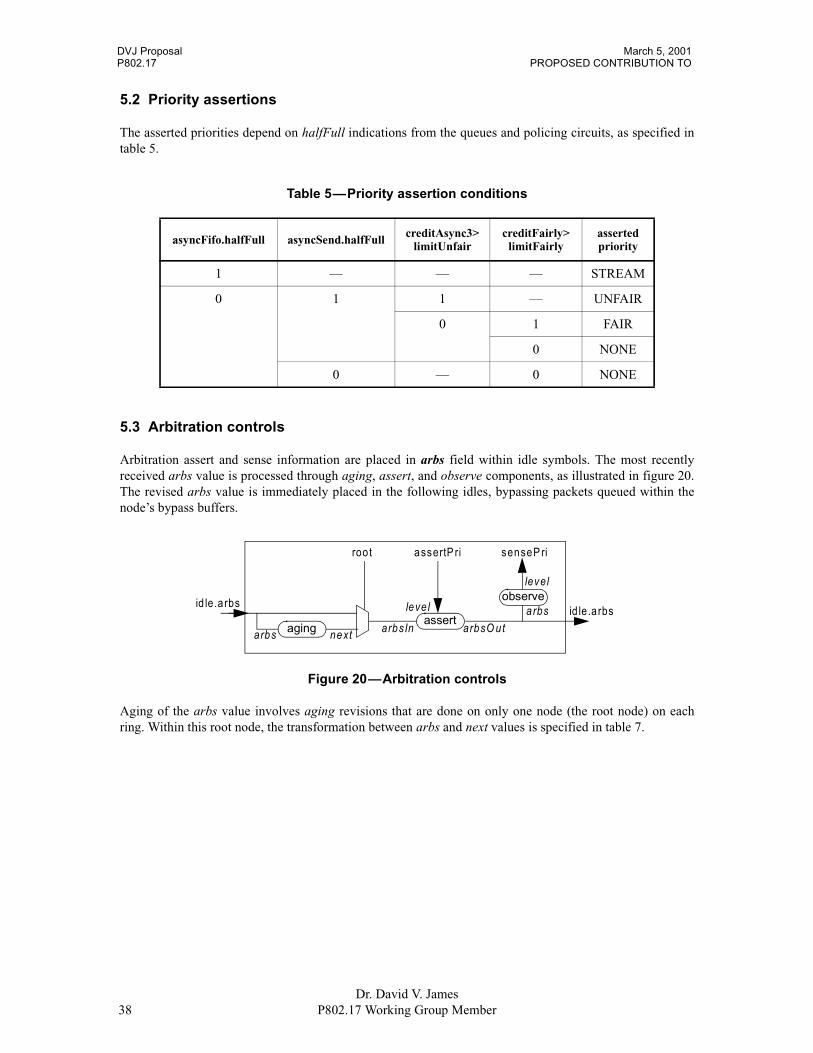
5.2 Priority assertions
The asserted priorities depend on halfFull indications from the queues and policing circuits, as specified intable 5.
5.3 Arbitration controls
Arbitration assert and sense information are placed in arbs field within idle symbols. The most recentlyreceived arbs value is processed through aging, assert, and observe components, as illustrated in figure 20.The revised arbs value is immediately placed in the following idles, bypassing packets queued within thenode’s bypass buffers.
Aging of the arbs value involves aging revisions that are done on only one node (the root node) on eachring. Within this root node, the transformation between arbs and next values is specified in table 7.
Table 5—Priority assertion conditions
asyncFifo.halfFull asyncSend.halfFull creditAsync3>limitUnfair
creditFairly>limitFairly
assertedpriority
1 — — — STREAM
0 1 1 — UNFAIR
0 1 FAIR
0 NONE
0 — 0 NONE
Figure 20—Arbitration controls
id le.a rbs
roo t assertP ri
assert
senseP ri
id le.a rbsaging nextarbs
observelevel
arbsIn arbsO ut
leve l a rbs

March 5, 2001 DVJ ProposalRESILIENT RING PROTOCOL (RRP) P802.17
Dr. David V. JamesP802.17 Working Group Member 39
Priority assertions involves transformations of the arbs indication, based on the nodes asserted priority level,as specified in table 6. Priority sensing involves classification of the outgoing arbs value to determine its pri-ority level, as specified in table 7.
Table 6—Arbitration assertion processing
inputs
Row
output
leve
l
arbs
stat
e
arbs
stat
e
go
NO
NE ARB_00, ARB_0A, ARB_1A, ARB_2A,
ARB_0B, ARB_1B, ARB_2B,ARB_03, ARB_13,ARB_23, ARB_33,ARB_04, ARB_14, ARB_24, ARB_34, ARB_44
— 1 -same- — 0
FAIR
ARB_00 — 2 ARB_10 — 1
ARB_0A, ARB_1A A 3 ARB_1A — 0
B 4 ARB_1B — 1
C 5 ARB_10 — 1
ARB_2A A 6 ARB_2A A 0
B 7
C 8
ARB_0B, ARB_1B A 9 ARB_1A — 1
B 10 ARB_1B — 0
C 11 ARB_10 — 1
ARB_2B A 12 ARB_2B B 0
B 13
C 14
ARB_03 — 15 ARB_13 — 0
ARB_04 — 16 ARB_14
ARB_13, ARB_23, ARB_33,ARB_14, ARB_24, ARB_34, ARB_44
— 17 -same-
UN
FAIR
ARB_00, ARB_0A, ARB_1A, ARB_2A,ARB_0B, ARB_1B,ARB_2B,ARB_03, ARB_13, ARB_23, ARB_33
— 18 ARB_33 —
ARB_04, ARB_14, ARB_24, ARB_34 — 19 ARB_34
ARB_44 — 20 ARB_44
STR
EA
M — — 21 ARB_44

DVJ Proposal March 5, 2001P802.17 PROPOSED CONTRIBUTION TO
Dr. David V. James40 P802.17 Working Group Member
For clarity, the rows within table 6 are further described below.
Row 1: A deasserted priority allows the arbs value to pass through unchanged.
Row 2: A FAIR asserted priority is asserted, with the intent of inhibiting other opportunistic transmissions.
Row 3: A FAIR priority is asserted, with the intent of receiving a future grant-B indication.
Row 4: The FAIR priority remains asserted, while blocking the current grant-A/grant-B wavefront.
Row 5: The FAIR priority remains asserted, while blocking the current grant-A/nogrant wavefront.
Row 6: Row 7: Row 8: The FAIR priority remains asserted, while waiting for grant-B/grant-A wavefront.
Row 9: The FAIR priority remains asserted, while blocking the current grant-A/grant-A wavefront.
Row 10: A FAIR priority is asserted, with the intent of receiving a future grant-B indication.
Row 11: The FAIR priority remains asserted, while blocking the current grant-B/nogrant wavefront.
Row 12: Row 13: Row 14: The FAIR priority remains asserted, before the grant-A/grant-B wavefront.
Row 15: The FAIR priority remains asserted, while waiting for the upstream level-3 arbitration to decrease.
Row 16: The FAIR priority remains asserted, while waiting for the upstream level-4 arbitration to decrease.
Row 17: A lower asserted priority allows the higher upstream arbs value to remain unchanged.
Row 18: A comparable UNFAIR priority overrides the upstream arbs value.
Row 19: A comparable UNFAIR request overrides the upstream arbs-resident request.
Row 20: The lower UNFAIR assertion leaves the arbs-resident assertions unchanged.
Row 21: The comparable STREAM assertion overrides the (equal or less) arbs-resident assertions.

March 5, 2001 DVJ ProposalRESILIENT RING PROTOCOL (RRP) P802.17
Dr. David V. JamesP802.17 Working Group Member 41
6. Maintenance activities
6.1 Loop counters
Loop counts are maintained by a distinctive node on the ring, called the root. This allows counts to beupdated flexibly, quickly, accurately, and with minimal additional implied ring-propagation latencies. Also,the simplified ttl (time to live) adjustments allows CRCs to be simply compensated, rather than recomputedfrom temporarily unprotected values.
The root is responsible for maintaining loop circulation counts for the benefit of other nodes. These countvalues are self-calibrating, so that systems continue to work correctly when the cable delays increase ordecrease from their previously established values. Three types of counters are maintained in a similarfashion, as illustrated in figure 21.
Equality comparisons between the root’s internal c0/c1 values and the observed like-named idle valuesdetermine when these idle-resident counts have successfully circulated and the c0/c1 values can be safelyupdated. The edgeDelay circuit inserts an additional latency L before the c0/c1 values are updated; the valueof L equals S*N, where S is the maximum packet size and N is the number of nodes on the ring. The intentis to inhibit the onset of restrictive arbitration protocols by artificially increasing the period between c0/c1value updates.
TBD - Verify that this actually has a period of 2**32-1, or pick another generator algorithm that does.With the limited 1-bit c0-field size, it is theoretically possible to have cyclical sequences of outstanding idlesymbols, whereupon idle[n].c0=0, idle[n+1].c0=1, idle[n+2].c0=0 and idle[n+4].c1=1 are concurrentlycirculating through the ring. To eventually eliminate such cycles, another pseudo-random c1 value isincluded in the idle symbols. The c1 value is generated by a pseudo random number generator generated bya 32-bit cCount register that is forced to a nonzero value.
The update rate of the c0 bit is based on the asynchronous-packet pass-through delays of these values in theattached nodes.
Figure 21—Loop count components
c00c01c02c03c04c05c06c07c08c09c10c11c12c13c14
pseudo-random number generator (forced to nonzero value)
c1
1:idle.c0
c15c16c17c18c19c20c21c22c23c24c25c26c27c28c29c30c31
1:idle.c1
c= (a==b) ca1:idle.c02:idle.c1
bc0
x
y
idle.arbs1:idle.arbs
edgeDelay y= !x
arbsAging
DVJ Proposal March 5, 2001P802.17 PROPOSED CONTRIBUTION TO
Dr. David V. James42 P802.17 Working Group Member
6.2 Packet aging
Multicast and unicast packets are normally scrubbed at their producing and consuming nodes respectively,based on their packet header components. However, packet headers can be occasionally corrupted bytransmission errors, which could generate invalid packet-header values.
The packet’s ttl (time-to-live) field is used to ensure timely scrubbing of such corrupted packet headers, asfollows:
1) Transmission, When transmitted, the packet’s header.ttl value is set to 3.2) Adjustments. When passing through the root node, nonzero header.ttl values shall be decremented.3) Discarding. When reaching the root node, packets with a zero-valued header.ttl shall be discarded.
6.3 CRC aging
Each packet’s CRC value is aged when passing through nodes. Aging involves logging the transmissionerror, then changing the bad CRC value to a distinctive stomp CRC value, to inhibit further error logging indownstream nodes. The stomp CRC value is defined to be the exclusive-OR of the valid CRC value an adefined STOMP value.
The STOMP value definition is (TBD).
March 5, 2001 DVJ ProposalRESILIENT RING PROTOCOL (RRP) P802.17
Dr. David V. JamesP802.17 Working Group Member 43
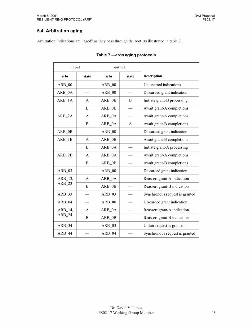
6.4 Arbitration aging
Arbitration indications are “aged” as they pass through the root, as illustrated in table 7.
Table 7—arbs aging protocols
input output
Descriptionarbs state arbs state
ARB_00 — ARB_00 — Unasserted indications
ARB_0A — ARB_00 — Discarded grant indication
ARB_1A A ARB_0B B Initiate grant-B processing
B ARB_0B — Await grant-A completions
ARB_2A A ARB_0A — Await grant-A completions
B ARB_0A A Await grant-B completions
ARB_0B — ARB_00 — Discarded grant indication
ARB_1B A ARB_0B — Await grant-B completions
B ARB_0A — Initiate grant-A processing
ARB_2B A ARB_0A — Await grant-A completions
B ARB_0B — Await grant-B completions
ARB_03 — ARB_00 — Discarded grant indication
ARB_13,ARB_23
A ARB_0A — Reassert grant-A indication
B ARB_0B — Reassert grant-B indication
ARB_33 — ARB_03 — Synchronous request is granted
ARB_04 — ARB_00 — Discarded grant indication
ARB_14,ARB_24
A ARB_0A — Reassert grant-A indication
B ARB_0B — Reassert grant-B indication
ARB_34 — ARB_03 — Unfair request is granted
ARB_44 — ARB_04 — Synchronous request is granted

DVJ Proposal March 5, 2001P802.17 PROPOSED CONTRIBUTION TO
Dr. David V. James44 P802.17 Working Group Member
6.5 Idle symbol pools
Each node has elasticity buffers that may insert or delete passing through idle symbols, based on thedifferences between their clock frequencies and the clock frequencies of their transmitting neighbors. Toensure successful operation of these elasticity buffers, idle symbol are managed in several ways, listedbelow:
1) Sending. When transmitting packets, a replicated idle (in addition to the packet’s EOF idle) isperiodically sent (this effectively extends the length of some packet by an additional idle symbol).
2) Recovering. While emptying the bypass FIFO, a periodic stream of deletable idles passes through.3) Adjustments. Elasticity buffers attempt to insert or delete idles, to maintain an approximately
constant distance between deletable idles.
The default distances between idles can increase if elasticity buffers in multiple nodes concurrently deletepassing-through idles. This has the temporary undesirable effect of temporarily starving other elasticitybuffer from desired deletable idles, and could (if allowed) cause elasticity buffer failures.
To minimize the worst-case idle-packet starvation conditions, the dynamics of the elasticity buffer areconstrained, as illustrated in figure 22. Desired deletions are normally deferred until consecutive deletableidles are encountered, or after a significant increase from the nominal elasticity depth. Similarly, desiredinsertions are normally deferred until an isolated nondeletable idle is encountered, or after a significantdecrease from the nominal elasticity depth.
The elasticity buffer behaves as a variable-delay storage element. Its idle-insertion and idle-deletiondecisions are based on the current elastic-buffer delay, as follows:
1) NeedMore. When the delays are short (beyond one below nominal), idles are inserted at the nextopportunity. The intent is to quickly restore the nominal elasticity delay.
2) WantMore. When the delays are shorter (within one below nominal), idle insertions are performed ifIDLE_SPACING symbols have been received since the last passed-through deletable idle. Theintent is to create an evenly-spaced set of deletable idles.
3) WantLess. When delays are longer (within one above nominal), idle deletions are performed ifIDLE_SPACING symbols have been received since the last passing-through deletable idle. Theintent is to maintain an evenly-spaced set of deletable idles.
4) NeedLess. When the delays are long (beyond one above nominal), the next deletable idle is deleted.The intent is to quickly restore the nominal elasticity delay.
The IDLE_SPACING constant value is physical-layer dependent and beyond the scope of this standard.
Figure 22—Elasticity delay-adjustment ranges
current delay0
n-1
n+1
2n
NeedMore
WantLess
NeedLess
WantMore
n

March 5, 2001 DVJ ProposalRESILIENT RING PROTOCOL (RRP) P802.17
Dr. David V. JamesP802.17 Working Group Member 45
6.6 Wallclock synchronization
6.6.1 Wallclock calibration
With bidirectional cables, the clockSync transmissions can account for the constant cable-induced delays, bymeasuring round-trip cable delays. Using such techniques, the accuracy of these wallclock synchronizationprotocols is dependent on the delay differences between incoming and outgoing links, not the overall delayof either. Implementation of these wallclock synchronization protocols involves monitoring the arrival anddeparture time of synchronous packets, called clockSync packets, as described in this subclause.
The root node is responsible for generation of clockSync packets. All nodes (root as well as nonroot) areresponsible for measuring the clockSync propagation time through themselves. Clock deviations aresampled in cycle N and calibrations are performed in cycle N+1. Clock sampling involves through-nodedelays measurements and sampling of the nodes clockTime value at its transmitter, as illustrated in figure 23.
The behaviors on transmissions to the right is as follows:
1) Root. The root forwards its right-side and left-side averaged transmit/receive time estimates:a) Right. The root sends the average of the observed right-side times, as follows:
timeSendright= sampled+(delayC−delayB)/2b) Left. The root sends the average of the observed left-side times, as follows:
timeSendleft= sampled+(delayA+delayB)/22) Core. The core computes its clock deviations and forwards an adjusted time estimate:
a) Deviation. The node computes its clock deviation, as follows:timeSink= sampled+(delayC−delayA)/2;timeDiff= timeSend−timeSink;
b) Core. The core sends the average of the observed right-side times, as follows:timeSendright= timeSendleft−(delayA+delayB)/2
3) Warp. The node computes its clock deviation, as follows:timeSink= sampled+(delayC−delayA)/2;timeDiff= timeSend−timeSink;
Figure 23—Clock and delay measurements
root core wrap
sampledclockTime
delayA
delayC
delayB
sampledclockTime
delayA
delayC
delayB
sampledclockTime
delayA
delayC
delayB
DVJ Proposal March 5, 2001P802.17 PROPOSED CONTRIBUTION TO
Dr. David V. James46 P802.17 Working Group Member
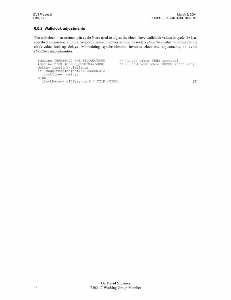
6.6.2 Wallclock adjustments
The wallclock measurements in cycle N are used to adjust the clock-slave wallclock values in cycle N+1, asspecified in equation 2. Initial synchronization involves setting the node’s clockTime value, to minimize theclock-value lock-up delays. Maintaining synchronization involves clock-rate adjustments, to avoidclockTime discontinuities.
#define THRESHOLD ONE_SECOND/8000 // Adjust after 8KHz interval#define TICK (CLOCK_NOMINAL/5000) // 200PPM overcomes 100PPM inaccuracydelta= timeSink-timeSend;if (Magnitude(delta)>(THRESHOLD/2))
clockTime+= delta;else
clockRate+= difference>0 ? TICK:-TICK; (2)

March 5, 2001 DVJ ProposalRESILIENT RING PROTOCOL (RRP) P802.17
Dr. David V. JamesP802.17 Working Group Member 47
7. Ring initialization
NOTE—The following initialization protocols are preliminary in nature. Detailed state machines, indication types, andindication codings are TBD.
In the absence of a configurable ringlet, ring initialization degrades to an spanning tree algorithm: spanningtree is formed and the ring is constructed by circumscribing this tree. These protocols support nearly arbi-trary cable topologies; extra cables may be inserted for redundancy or performance reasons, or may beinstalled by an uninformed user.
In the presence of a ring topology, ring initialization deviates from the 802-defined spanning tree algorithm,in its support of ringlet connections, as follows:
1) Dual ringlets. A ring is normally closed, enabling efficient use of counter-rotating ringlets.
2) Single ringlet. An defective ring can be closed, enabling efficient use of a single ringlet.
Dual ringlets deliver more than twice the performance, because packets can travel on either cable an in apreferential direction. Thus, ring cable topologies are not only possible, they are highly desirable from afault-tolerance perspective.
7.1 Bus reset functionality
Resets begin with the detection of a reset condition (typically the addition or removal of a cable or device),which forces one or more of the nodes into a “contending root” condition. A contending root is responsiblefor distributing its EUI-64 (an extended unique identifier) to its adjacent neighbors, by including this EUI-64in reset packets sent to its neighbors. The contending root is also responsible for exploring the interconnect,and changes to a branch or leaf when a larger EUI-64 is observed.
The contending root waits for its reset packets to return. If its reset returns on the outgoing-reset port, thereset is sent out the next (previously inactive) port. Alternatively, if the reset returns on a different port, thatport is set to a loop-back mode. Using this algorithm, the resets propagate through the interconnect,establishing its active topology, as illustrated in the left half of figure 24.
A reset initializes the bus and bypasses ports that are identified as unusable or redundant. Port are bypassinvolves electronically-switched circuits within the node; no relays or termination-plug components arerequired.
A bus reset can be initiated by any node, but is completed by the node that was selected to become the root.The root node is selected from among the root-capable nodes, based on the node’s root-selection bits (whichcan be set by software) and its eui64 identifier (which is fixed when the node is manufactured).
Figure 24—Bus reset sequences
1 2 3 4 5
678
91011
13 1214

DVJ Proposal March 5, 2001P802.17 PROPOSED CONTRIBUTION TO
Dr. David V. James48 P802.17 Working Group Member
Resets have the following properties:
1) Autonomous. The system is self configuring, yielding one of the following two configurations:a) Efficient. When a daisy-chained loop is reset, an active counter-rotating ringlet is formed.b) Sufficient. When other arbitrary topologies are reset, a (less efficient) active ringlet is formed.
2) Simple. Reset protocols are design to be easily implemented, in the following ways:a) Two-port optimized. The reset protocols are optimized for simple 1-port and 2-port nodes.b) Simple compares. A node only compares incoming reset-packet identifiers to its own.c) Self timed. The protocols are speed insensitive, so low-speed compare logic can be used.
However, processing delays are constrained to reduce the worst-case bus reset latencies.3) Repeatable. A reset consistently yields the same root and active-cable topology, unless the physical
cabling topology has actually changed.
7.2 Reset packets
7.2.1 Reset identifiers
Each node is assumed to be manufactured with a 64-bit unique identifier (EUI-64). The resetId is formed byconcatenating a software precedence field to this EUI-64 value, forming a 72-bit identifier. The node withthe largest resetId is selected to become the root; each child can identify its parent by the port on which thelargest resetId value was last observed. By convention, the lowest resetId (corresponding to all zeros) isasserted by non-root capable nodes, or by root-capable nodes that are currently resetting other links.
Although each node is mandated to have a globally unique EUI-64 identifier (see xx), only the root-capablenodes need to manage these values during bus reset sequences. Dual ported nodes that are not root capablehave to forward observed resets through them, but have no need to compare passing through resetIds to theirown.
7.2.2 Reset packet types
Several forms of reset packets are distributed during a bus reset, as listed below:
TBDs
When reset and flush packets are being sent, they are sent with only a few interspersed idles. A smallnumber of idles are necessary to provide idle-deletion opportunities. Too many idles would make it difficultto detect absence-of-reset conditions, due to dead or disconnected nodes.

March 5, 2001 DVJ ProposalRESILIENT RING PROTOCOL (RRP) P802.17
Dr. David V. JamesP802.17 Working Group Member 49
7.3 Ringlet initialization effects
7.3.1 Duplex ring initialization
As example, a duplex ringlet is configures after a cable is plugged into two previously unconnected ports,forming a ring, as illustrated in figure 25. The connection of a cable allows each of the attached ports toobserve each others heartbeats, quickly responding to the newly attached cable. The cable connected state isquickly reported by the ports on nodes b and d, which initiates their reset activities. The aftermath of thereset-invoked initialization changes the configured node topology, by forming more efficient dual ringletconnections.
7.3.2 Daisy chain initialization
As another example, a cable is removed from two of the previously connected ports, severing a ring, asillustrated in figure 26. The cable deletion initiates a bus reset; the aftermath of the bus resets changes theconfigured node topology, forming less efficient single ringlet connections.
7.3.3 Primary link fault-induced reset
As another example, the secondary link within the duplex cable may fail, as illustrated in figure 27. The linkfailure initiates a bus reset; the aftermath of the bus resets changes the configured node topology, formingless efficient single ringlet connections.
Figure 25—Duplex ring reset
Figure 26—Daisy chain formed
Figure 27—Primary link fault-induced reset
b
d
(1)c
a
(2)
b a
d
c
(1)
b a
d
c (2)
b a
c
d
(1)
b a
d
c (2)
b a
d
c

March 5, 2001 DVJ ProposalRESILIENT RING PROTOCOL (RRP) P802.17
Dr. David V. JamesP802.17 Working Group Member 50
7.3.4 Secondary link fault-induced reset
As another example, the secondary link within the duplex cable may fail, as illustrated in figure 27. The linkfailure initiates a bus reset; the aftermath of the bus resets changes the configured node topology, formingless efficient single ringlet connections.
7.3.5 Forced tree reset
As another example, the side node may be attached to an existing ring, as illustrated in figure 29. The cableattachment initiates a bus reset; the aftermath of the bus resets changes the configured node topology, form-ing less efficient circumscribing ringlet connections.
7.3.6 Redundant ring recovery
As another example, an active/redundant cable may be severed or removed, as illustrated in figure 30. Thecable detachment initiates a bus reset; the aftermath of the bus resets changes the configured node topology,forming an alternative (but equally efficient) dual-ringlet connections.
Figure 28—Secondary link fault induced reset
Figure 29—Forced tree reset
Figure 30—Redundant ring recovery
(1)
b a
d
c (2)
b a
d
c
(1)
b
c
d
a
(2)
c
d
a
b
(1)
b
d
c
(2)
d
cb

DVJ Proposal P802.17 PROPOSED CONTRIBUTION TO RESILIENT RING PROTOCOL (RRP) 1March 5, 2001
Dr. David V. JamesP802.17 Working Group Member
Annex G
(normative)
Code listing

DVJ Proposal P802.17 PROPOSED CONTRIBUTION TO RESILIENT RING PROTOCOL (RRP) 2March 5, 2001
Dr. David V. JamesP802.17 Working Group Member
March 5, 2001DVJ Proposal P802.17 PROPOSED CONTRIBUTION TO RESILIENT RING PROTOCOL (RRP) C Code–1
1 1 1 11 2 3 4 5 6 7 8 9 0 1 2 3
0123456789012345678901234567890123456789012345678901234567890123456789012345678901234567890123456789012345678901234567890123456789012
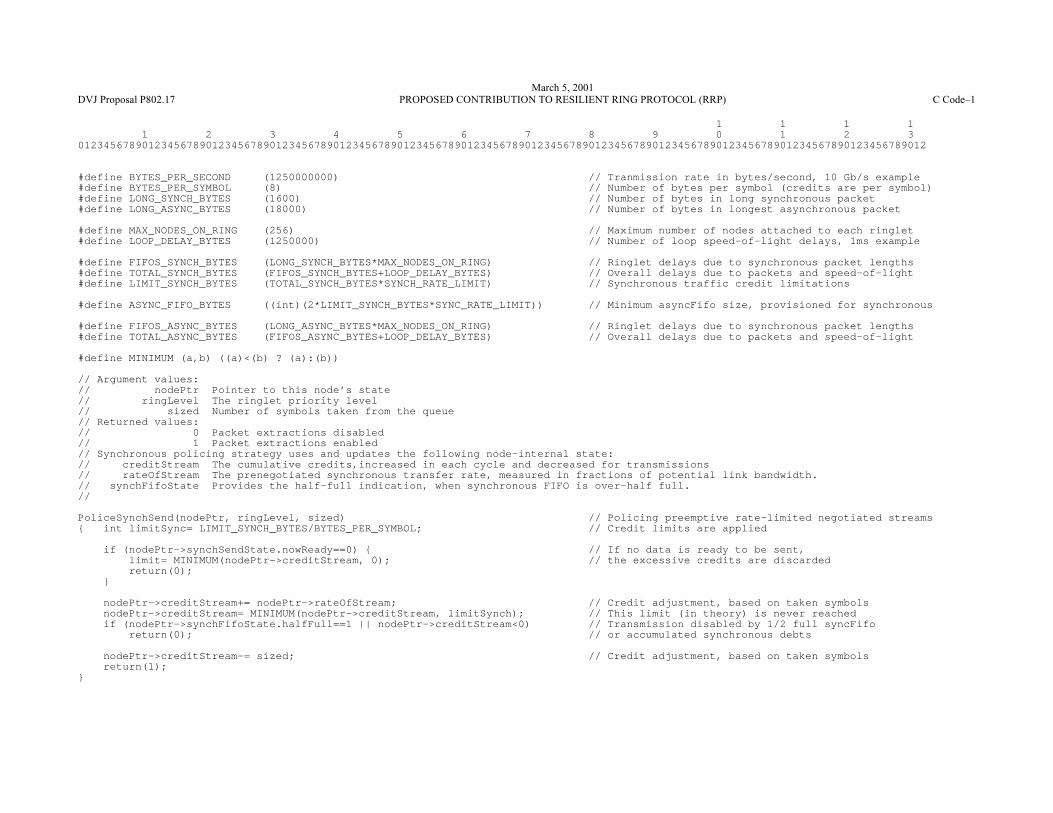
#define BYTES_PER_SECOND (1250000000) // Tranmission rate in bytes/second, 10 Gb/s example#define BYTES_PER_SYMBOL (8) // Number of bytes per symbol (credits are per symbol)#define LONG_SYNCH_BYTES (1600) // Number of bytes in long synchronous packet#define LONG_ASYNC_BYTES (18000) // Number of bytes in longest asynchronous packet
#define MAX_NODES_ON_RING (256) // Maximum number of nodes attached to each ringlet#define LOOP_DELAY_BYTES (1250000) // Number of loop speed-of-light delays, 1ms example
#define FIFOS_SYNCH_BYTES (LONG_SYNCH_BYTES*MAX_NODES_ON_RING) // Ringlet delays due to synchronous packet lengths#define TOTAL_SYNCH_BYTES (FIFOS_SYNCH_BYTES+LOOP_DELAY_BYTES) // Overall delays due to packets and speed-of-light#define LIMIT_SYNCH_BYTES (TOTAL_SYNCH_BYTES*SYNCH_RATE_LIMIT) // Synchronous traffic credit limitations
#define ASYNC_FIFO_BYTES ((int)(2*LIMIT_SYNCH_BYTES*SYNC_RATE_LIMIT)) // Minimum asyncFifo size, provisioned for synchronous
#define FIFOS_ASYNC_BYTES (LONG_ASYNC_BYTES*MAX_NODES_ON_RING) // Ringlet delays due to synchronous packet lengths#define TOTAL_ASYNC_BYTES (FIFOS_ASYNC_BYTES+LOOP_DELAY_BYTES) // Overall delays due to packets and speed-of-light
#define MINIMUM (a,b) ((a)<(b) ? (a):(b))
// Argument values:// nodePtr Pointer to this node’s state// ringLevel The ringlet priority level// sized Number of symbols taken from the queue// Returned values:// 0 Packet extractions disabled// 1 Packet extractions enabled// Synchronous policing strategy uses and updates the following node-internal state:// creditStream The cumulative credits,increased in each cycle and decreased for transmissions// rateOfStream The prenegotiated synchronous transfer rate, measured in fractions of potential link bandwidth.// synchFifoState Provides the half-full indication, when synchronous FIFO is over-half full.//
PoliceSynchSend(nodePtr, ringLevel, sized) // Policing preemptive rate-limited negotiated streams{ int limitSync= LIMIT_SYNCH_BYTES/BYTES_PER_SYMBOL; // Credit limits are applied
if (nodePtr->synchSendState.nowReady==0) { // If no data is ready to be sent,limit= MINIMUM(nodePtr->creditStream, 0); // the excessive credits are discardedreturn(0);
}
nodePtr->creditStream+= nodePtr->rateOfStream; // Credit adjustment, based on taken symbolsnodePtr->creditStream= MINIMUM(nodePtr->creditStream, limitSynch); // This limit (in theory) is never reachedif (nodePtr->synchFifoState.halfFull==1 || nodePtr->creditStream<0) // Transmission disabled by 1/2 full syncFifo
return(0); // or accumulated synchronous debts
nodePtr->creditStream-= sized; // Credit adjustment, based on taken symbolsreturn(1);
}
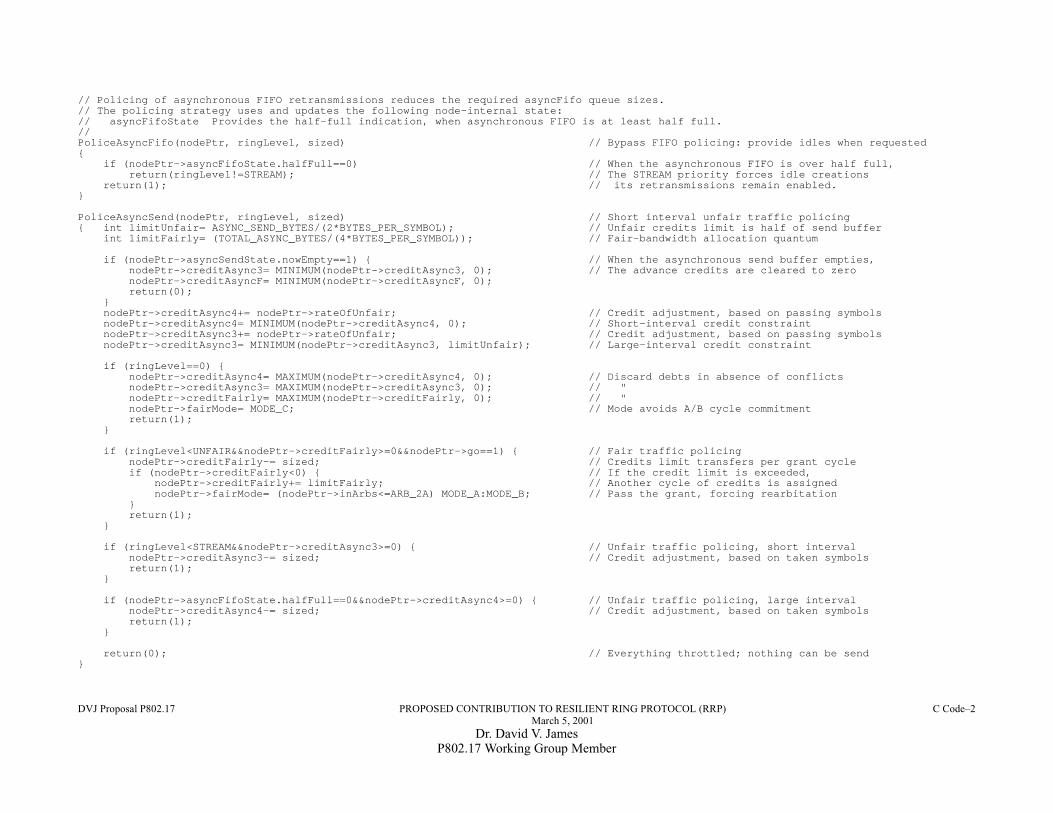
DVJ Proposal P802.17 PROPOSED CONTRIBUTION TO RESILIENT RING PROTOCOL (RRP) C Code–2March 5, 2001
Dr. David V. JamesP802.17 Working Group Member
// Policing of asynchronous FIFO retransmissions reduces the required asyncFifo queue sizes.// The policing strategy uses and updates the following node-internal state:// asyncFifoState Provides the half-full indication, when asynchronous FIFO is at least half full.//PoliceAsyncFifo(nodePtr, ringLevel, sized) // Bypass FIFO policing: provide idles when requested{
if (nodePtr->asyncFifoState.halfFull==0) // When the asynchronous FIFO is over half full,return(ringLevel!=STREAM); // The STREAM priority forces idle creations
return(1); // its retransmissions remain enabled.}
PoliceAsyncSend(nodePtr, ringLevel, sized) // Short interval unfair traffic policing{ int limitUnfair= ASYNC_SEND_BYTES/(2*BYTES_PER_SYMBOL); // Unfair credits limit is half of send buffer
int limitFairly= (TOTAL_ASYNC_BYTES/(4*BYTES_PER_SYMBOL)); // Fair-bandwidth allocation quantum
if (nodePtr->asyncSendState.nowEmpty==1) { // When the asynchronous send buffer empties,nodePtr->creditAsync3= MINIMUM(nodePtr->creditAsync3, 0); // The advance credits are cleared to zeronodePtr->creditAsyncF= MINIMUM(nodePtr->creditAsyncF, 0);return(0);
}nodePtr->creditAsync4+= nodePtr->rateOfUnfair; // Credit adjustment, based on passing symbolsnodePtr->creditAsync4= MINIMUM(nodePtr->creditAsync4, 0); // Short-interval credit constraintnodePtr->creditAsync3+= nodePtr->rateOfUnfair; // Credit adjustment, based on passing symbolsnodePtr->creditAsync3= MINIMUM(nodePtr->creditAsync3, limitUnfair); // Large-interval credit constraint
if (ringLevel==0) {nodePtr->creditAsync4= MAXIMUM(nodePtr->creditAsync4, 0); // Discard debts in absence of conflictsnodePtr->creditAsync3= MAXIMUM(nodePtr->creditAsync3, 0); // "nodePtr->creditFairly= MAXIMUM(nodePtr->creditFairly, 0); // "nodePtr->fairMode= MODE_C; // Mode avoids A/B cycle commitmentreturn(1);
}
if (ringLevel<UNFAIR&&nodePtr->creditFairly>=0&&nodePtr->go==1) { // Fair traffic policingnodePtr->creditFairly-= sized; // Credits limit transfers per grant cycleif (nodePtr->creditFairly<0) { // If the credit limit is exceeded,
nodePtr->creditFairly+= limitFairly; // Another cycle of credits is assignednodePtr->fairMode= (nodePtr->inArbs<=ARB_2A) MODE_A:MODE_B; // Pass the grant, forcing rearbitation
}return(1);
}
if (ringLevel<STREAM&&nodePtr->creditAsync3>=0) { // Unfair traffic policing, short intervalnodePtr->creditAsync3-= sized; // Credit adjustment, based on taken symbolsreturn(1);
}
if (nodePtr->asyncFifoState.halfFull==0&&nodePtr->creditAsync4>=0) { // Unfair traffic policing, large intervalnodePtr->creditAsync4-= sized; // Credit adjustment, based on taken symbolsreturn(1);
}
return(0); // Everything throttled; nothing can be send}

March 5, 2001DVJ Proposal P802.17 PROPOSED CONTRIBUTION TO RESILIENT RING PROTOCOL (RRP) C Code–3