Embed Size (px)
Citation preview

PROPOSAL TITLE
Investigating Implementation Potentials of Turbo Roundabouts in Nevada
PRINCIPAL INVESTIGATORS
Kakan C Dey, PhD, PE (Principal Investigator)
Assistant Professor
Department of Civil and Environmental Engineering
West Virginia University
ESB 647, 1374 Evansdale Drive
Morgantown, West Virginia, 26506-6070
Phone: 304-293-9952, Email: [email protected]
Bhaven Naik, PhD, PE, PTOE, RSP (Co-Principal Investigator)
Associate Professor
Department of Civil Engineering
Ohio University
226 Stocker Center, Athens, Ohio. 45701
Phone: 740 593 4151, Email: [email protected]

i
TABLE OF CONTENTS
1. PROBLEM DESCRIPTION ................................................................................................... 1
2. BACKGROUND SUMMARY ............................................................................................... 1
3. PROPOSED RESEARCH ...................................................................................................... 3
Task 1. Hold project start-up meeting ........................................................................................ 4
Task 2. Review pertinent existing literature and best practices ................................................. 4
Task 3. Perform micro-simulation assessment .......................................................................... 4
Task 3.1: Site selection ........................................................................................................... 5
Task 3.2: Data collection at selected sites .............................................................................. 5
Task 3.3: Development of the calibrated models .................................................................... 5
Task 3.4: Simulation scenario development ........................................................................... 5
Task 3.5: Simulation and estimation of performance measures ............................................. 5
Task 4. Perform human factors (or driver experience) assessment ........................................... 6
Task 4.1. Submission of Institutional Review Board (IRB) approval .................................... 6
Task 4.2. Develop simulator scenarios ................................................................................... 7
Task 4.3. Participant recruitment ............................................................................................ 7
Task 4.4. Run test and experiment drives ............................................................................... 7
Task 5. Develop a selection procedure for turbo roundabouts ................................................. 7
Task 6. Develop educational resources and conduct effectiveness analysis ............................. 7
Task 7. Develop an implementation plan .................................................................................. 8
Task 8. Develop recommendations and final project report ...................................................... 8
Task 9. Conduct project management tasks ............................................................................... 8
4. URGENCY AND ANTICIPATED BENEFITS .................................................................... 8
5. IMPLEMENTATION PLAN ................................................................................................. 9
6. PROJECT SCHEDULE .......................................................................................................... 9
7. FACILITIES AND EXPERTISE ........................................................................................... 9
8. PROJECT CHAMPION, COORDINATION, AND INVOLVEMENT ............................. 10
9. BUDGET .............................................................................................................................. 11
10. APPENDIX A: EXTENDED LITERATURE REVIEW .................................................. 13
11. REFERENCES .................................................................................................................. 24
12. APPENDIX B: CVs ........................................................................................................... 27
Kakan Chandra Dey, PhD, PE .................................................................................................. 27
Bhaven Naik, PhD, PE, PTOE, RSP. ........................................................................................ 31
1
1. PROBLEM DESCRIPTION
Multi-lane roundabouts have been used as a proven safety strategy for improving intersection safety by
eliminating or altering conflict types and reducing crash severity. Despite these advantages, multi-lane
roundabouts have several operational challenges such as driver confusion on proper lane choice decisions, striping
and signing issues, and concerns with the frequency of crashes (1). A relatively new form of roundabout referred
to as “turbo roundabout” has the potential to reduce the limitations encountered by multi-lane roundabouts. A
turbo roundabout's configuration can effectively guide drivers to reduce lane-change conflicts common in multi-
lane roundabouts (2). A turbo roundabout has ten conflict points compared to sixteen conflict points in a
traditional two-lane roundabout. In addition to safety benefits, a turbo roundabout could provide higher capacity
due to reduced conflict points (3). Moreover, a turbo roundabout can potentially be installed at locations where a
single-lane roundabout does not provide enough capacity, and a two-lane roundabout increases conflict. A turbo
roundabout was first designed and implemented in the Netherlands (4), where a before and after safety analysis
showed a 53% reduction in injury crashes (5). While several features of a turbo roundabout have been adopted in
few “turbo-like” roundabouts (e.g., Main Street in Mesa, Arizona; Utah Valley University, Orem, UT), there are
no standard/typical turbo roundabout installed yet in the U.S. (6).
While there are design standards/guidelines for turbo roundabouts in the context of transportation systems and
roadway users’ characteristics in several European countries, these standards cannot be readily transferable to the
U.S. The European design vehicle (e.g., tractor-trailer) is shorter than the U.S. standard tractor-trailer. Wider
circulating lanes or longer outer truck aprons are required to accommodate longer tractor-trailer(s) in the U.S. For
example, a wider opening width is required to accommodate the swept path of the U.S. tractor-trailer, according
to an analysis by Transoft Solution (6). Besides, driver behavior and familiarity towards roundabouts (in general)
and turbo roundabouts (in particular) are different (e.g., U.S. drivers are less familiar with roundabouts). The
Nevada DOT has been adopting roundabouts to improve safety and operations at intersections on their state
highways and is currently considering installing turbo roundabouts. Therefore, a detailed investigation using
microsimulation and driving simulator tools considering diverse roadway users (e.g., passenger cars, trucks,
pedestrians, bikes) and traffic volume composition (e.g., truck percentages and truck configurations) are critical
before any installation of turbo roundabouts in Nevada. An analysis of this kind (details presented in Research
Plan Section) will allow the development of design guidelines, installation criteria (e.g., warrants), and operational
recommendations that are specific to local (in this case, Nevada) roadway, traffic, and driver/user characteristics.
This project’s overall goal is to develop guidelines for the Nevada DOT on the installation and performance of
turbo roundabouts. As there are no known installations of turbo roundabout in the U.S., any kind of guidance that
can assist with decision making is not available for transportation engineers, professionals, and consultants.
Therefore, there is a need to synthesize and summarize current research, and more importantly, develop a
mechanism that guides practitioners on how to decide on the installation of a turbo roundabout, such as installation
criteria, design guidelines, safety and operational performance. To accomplish the project goal, the West Virginia
University (WVU) and Ohio University (OHIO) team aims to accomplish the following specific objectives:
[1] Conduct an extensive review and synthesis of current published research and pilot projects that compile the
design, installation, operation, maintenance, safety, and operational performance of turbo roundabouts;
[2] Conduct an extensive traffic microsimulation-based investigation that will provide insights on different design
factors in developing design guidelines, ensuring safety, and enabling effective operations and maintenance
of turbo roundabouts;
[3] Conduct a driving simulator-based investigation to understand navigability differences between traditional
and turbo roundabout designs and subsequently lead to identifying improvements or precautions (if any) that
would be needed in developing design guidelines and educational resources; and
[4] Develop a procedure (e.g., warrant analysis) and evaluation tool to assist transportation
engineers/professionals (Nevada specific) with further evaluation of turbo roundabout installation.
2. BACKGROUND SUMMARY
As intersection related traffic crashes represent approximately 50% of total traffic crashes (7), conversion of
traditional intersections (i.e., two- and all-way stop-controlled and signalized) to roundabouts has been a growing
practice in many countries around the world, including the U.S. The significant benefits of roundabouts include

2
reducing crash frequency and severity, capacity improvement, and operational improvement. A study by the
Federal Highway Administration (FHWA) reported that a roundabout reduces intersection fatality by 90%, injury
by 76%, and crash frequency by 35% compared to a traditional intersection (8). The acceptance of roundabout
increases substantially after the installation as drivers become knowledgeable on navigating roundabouts (9).
According to Kittleson & Associates database, as of 2020, there are 4,963 single-lane and 1,826 multi-lane
roundabouts in the U.S. (10). However, multi-lane roundabouts have several operational challenges, such as
driver’s improper lane choice decisions due to driver confusion and traffic safety concerns due to traffic crashes
from weaving movements within roundabout (11). Emerging “turbo roundabout” can reduce several limitations
of multi-lane roundabouts. Turbo roundabout can effectively guide drivers within the roundabout by limiting
lane-changing and reducing associated lane-change related conflicts/crashes common in multi-lane roundabouts
(12). The turbo roundabout (illustrated in Figure A.1, Appendix A) was first designed and implemented in the
Netherlands (13). Turbo roundabout has the same general operating characteristics as modern roundabouts but
utilizes different geometrics and traffic control devices (12).
The key features of turbo roundabouts are explained and illustrated in Figure A.2 (Appendix A). Lane
separator/barrier between circular lanes in turbo roundabout keeps vehicles in the same lane, and prevents
weaving maneuvers. A study on seven intersections converted into turbo roundabouts in the Netherlands observed
an 82% reduction in the accident rate (13). Different turbo roundabouts can be identified based on the variable
number of lanes on the access and exit legs. A four-legged turbo roundabout may have five variations (a) basic,
(b) egg, (c) knee, (d) spiral, and (e) rotor. A description of each type of turbo roundabout can be found in the
extended literature review (Figure A.3, Appendix A).
User considerations in turbo roundabout design: Turbo roundabouts guide the motorists before entering the
intersection to choose the assigned lane for right-turn, through movement, left-turn, and U-turn by entry geometry,
enhanced delineation of lanes, and proper road marking and signage (12, 14). The navigation of pedestrians and
bicyclists through a turbo roundabout is like single-lane and multilane roundabouts. The guidelines for pedestrian
includes keeping sidewalks along the perimeter of the roundabout; crosswalks provided for pedestrian
convenience and safety; adding a splitter island sufficiently wide to accommodate pedestrian crossing that is also
accessible to pedestrians with disabilities as well as wide enough for comfortable queueing (12, 14, 15). The
decision of whether to add separated bicycle facilities at turbo roundabouts depends on factors such as bicycle
volume, the presence of existing bicycle facilities, traffic volume, the complexity of the roundabout, adjacent
infrastructure, land use, and right-of-way availability (12, 14). Motorcycle safety at roundabouts can be influenced
by raised lane dividers and curbing, surface friction, pavement markings, drainage, sight distance, radius, the
roadside environment, and surface conditions. Specific concerns for motorcyclists in turbo roundabouts are the
raised truck apron and lane divider. Sloped curbing with minimal vertical reveal can be provided for a safer
environment for motorcycles than vertical or rolled curbing. Additional signage alerting motorcyclists to these
elements of turbo roundabouts can also be provided (14).
As vehicles aren’t allowed to change lanes within a turbo roundabout, it is critical to provide sufficient space for
large trucks to complete the movements/turning. In European design guidelines for turbo roundabouts, the
dimension of the design vehicle is considered so that design vehicles do not track into adjacent lanes (16).
However, trucks are larger in the U.S. compared to Europe. When a raised lane divider option is used, a traversable
and demarcating feature can be provided at the origin of the raised divider to ease the entrance of larger vehicles
(12). A central truck apron can be provided in turbo roundabouts to help larger vehicles to navigate the
intersection. Aprons can also be provided on the turbo roundabout's perimeter to provide more turning space for
large trucks (12). Accommodation of different user groups (i.e., motorists, pedestrians, bicyclists, motorcyclists,
and freight/large vehicles) at turbo roundabouts can be found in the extended literature review (Appendix A).
Location considerations: Site characteristics that can influence the feasibility of a turbo roundabout include right-
of-way limitations, intersection skewness, winter maintenance needs, and downstream bottlenecks. Turbo
roundabouts may be considered at an intersection where traffic demand indicates the need for a multilane
roundabout (12).
Design considerations: The geometric design of a turbo roundabout depends on the desired capacity and the
desired characteristics of a design vehicle’s horizontal swept path. The projected demand and the approach
roadway cross-sections determine the number of lanes/lane arrangement, which dictate the type of turbo

3
roundabout to be built. After selecting the type, a horizontal swept path analysis of the design vehicle is done to
choose lane width and other lane width-related considerations (e.g., right-of-way, considerations for all vehicle
types and users) (12). Current guidelines in terms of horizontal design components of turbo roundabout (i.e.,
Turbo Block, Lane and Roadway Width, Central Island, Lane Divider, Approach Geometry) are discussed in the
extended literature review (Appendix A).
Adequate stopping and decision sight distance should be provided for all users at all approaches of a turbo
roundabout. NCHRP Report 672 provides guidelines for evaluating sight distance and visibility at roundabouts
(14). Signage and pavement markings on the approaches, especially for lane selection, are critical for motorists
to identify and select their desired lane before entering the turbo roundabout. Lane control signage can be
supplemented using pavement marking arrows (12). Supplemental delineation can be achieved using reflectors
or light-emitting diodes (LEDs) to illuminate the edges of the apron and lane dividers (12, 17). Consideration of
pedestrian, bicycle, vertical alignment, lighting, landscaping, and other design aspects are presented in the
extended literature review (Appendix A).
Safety performance of turbo roundabout: As turbo roundabouts are still an emerging concept, international safety
studies based on an analysis of crash data are limited and not yet available based on any U.S. installation. In the
Netherlands, seven intersections were converted to a turbo roundabout and reported an 82% percent reduction in
the number of injury crashes (4). A study in Poland found that turbo roundabouts with a raised lane divider
experience a lower crash frequency than those with paint stripes only, and the researchers observed lower severity
crash outcomes in both cases (18). Surrogate safety measures based on microscopic traffic simulations have also
indicated that turbo roundabouts are likely to experience less frequent and less severe crashes than multilane
roundabouts (19, 20, 21, 22, 23).
Operational performance of turbo roundabout: Another advantage of the turbo roundabout is that the traffic flow
on lanes can be much more balanced (13). Similar to traditional roundabouts, the capacity of turbo roundabout is
measured at the approach level. International studies suggest that basic turbo roundabouts have a similar capacity
as multilane roundabouts with two entry and two circulating lanes. One study in the Netherlands estimated a
capacity for a basic turbo roundabout design of approximately 3,500 pc/h for all entries combined, assuming
conflicting traffic volumes between 1,900 and 2,100 pc/h (24). For estimating turbo roundabout capacity, gap-
acceptance models that consider critical headway, critical follow-up time, and conflicting traffic appear to be
adequate. A study in Poland found that the Highway Capacity Manual (HCM) capacity models for roundabouts
estimated the capacity of Polish turbo roundabouts with reasonable accuracy (25).
Costs: As turbo roundabouts are similar to multilane roundabouts, they are expected to have similar costs as multi-
lane roundabouts. Turbo roundabouts may vary slightly from multilane roundabouts in terms of right-of-way
requirements. A radial entry with no flare and smaller entrance radius requires a larger swept path for large
vehicles, which will lead to a wider circular roadway than for a comparable multilane roundabout. However, there
may not be significant changes to the alignment of the approach roadway given the entry geometry of the turbo
roundabout (12).
As there are no turbo roundabout design guidelines in the U.S. considering operational and safety performance of
different design features, a detailed investigation using microsimulation and driving simulator tools considering
diverse roadway users and traffic composition is timely to promote turbo roundabout in Nevada. The following
section summarized the research plan to be applied to facilitate the development of design guidelines and
installation criteria (e.g., warrants) specific to local (in this case, Nevada) roadway, traffic, and driver
characteristics.
3. PROPOSED RESEARCH
The work plan that has been developed is based on the scope of work defined within the RFP solicitation. The
WVU and OHIO research team has planned nine tasks to be completed in an orderly and timely manner to
accomplish the research objectives. These specific tasks include Task 1. Hold project start-up meeting; Task 2.
Review pertinent existing literature and best practices; Task 3. Perform microsimulation-based assessment; Task
4. Perform human factors (or driver experience) assessment; Task 5. Develop a selection procedure for turbo
roundabouts as intersection control option; Task 6: Develop educational materials and conduct effectiveness
analysis; Task 7: Develop implementation plan; Task 8. Develop recommendations and final project report; and

4
Task 9. Conduct project management tasks. The proposed research is expected to be completed in 24 months.
The project schedule section shows a detailed tentative timeline needed to complete tasks 1 to 8. This timeline
includes 23 months to complete project Tasks 1-8 and compile a draft report, and one month for review and
publication of the final project report. Details regarding each task and subtasks are presented below.
Task 1. Hold project start-up meeting
In the first month of the project contract award, the WVU and OHIO research team will schedule a virtual meeting
(e.g., ZOOM platform) with Nevada DOT’s project technical panel assigned to this project to present, discuss,
and finalize the following: detailed work plans, the scope of work, research methodology and tasks, project
duration/timeline, and deliverables.
Task 2. Review pertinent existing literature and best practices
For this task, extensive literature searches will be conducted through web-based queries as well as queries through
specific agency search engines (such as the Transportation Research International Database, NCHRP Projects,
Google Scholar, ScienceDirect, JSTOR, BIOSYS, and ResearchGate). Overall, and to the best knowledge of the
authors, there have been no adoptions/pilot projects of turbo roundabouts in the U.S. Though, there has been some
traction at FHWA, various state agencies, and consultant level to discuss possible implementation of this
alternative roundabout design. As turbo roundabouts have been adopted in Europe in the last few decades, this
literature search intends to summarize the design standards and safety and mobility benefits experiences. A library
search through the West Virginia University, OHIO Link, and OHIO library systems will be undertaken.
All available documentation (e.g., papers, synthesis reports, brochures) will be critically reviewed and targeted at
providing comprehensive and detailed insights on turbo roundabouts, including (but not limited to) the following:
[1] What design criterion (e.g., radii, entry point features, markings, signage) are standard, and adopted by
European countries for turbo roundabouts? This may entail direct communication with responsible parties in
European countries. [2] What considerations need to be made in terms of placement? That is, what
traffic/truck/pedestrian/bike volumes, roadway elements, environmental, safety, locale requirements need to be
evaluated to maximize benefit? [3] What are the operational, safety, and environmental improvements attained
from turbo roundabouts? [4] Any intersection performance advantages (e.g., capacity) of adopting turbo
roundabouts? [5] Any specific guidance – “best” practices, maintenance procedures, right-of-way requirements
in the use of turbo roundabouts?
Additionally, via email correspondence and/or phone interviews, the research team will reach out to the authors
of research articles related to turbo roundabouts. This personal communication will allow the research team to
get additional insights beyond that detailed in any existing literature. A comprehensive state-of-the-art literature
review will be prepared to contain the summaries and critiques from different perspectives, including; geometric
design, construction and maintenance, operations, safety, and driver experience. A report will be prepared as
the deliverable of this task and will be submitted to Nevada DOT. Appendix A summarizes an extended
literature review.
Task 3. Perform micro-simulation assessment
The research team adopts a micro-simulation approach to investigate the safety, and operational impacts of
different turbo roundabout design features considering diverse roadway users (e.g., passenger vehicle, truck,
pedestrian, bicyclist) in the U.S. Micro-simulation models “mimic closely the stochastic and dynamic nature of
both the vehicle-to-vehicle and vehicle-to-traffic interactions that occur within the transportation system” (26).
Additionally, variations in traffic volumes and their compositions (e.g., truck percentage and design vehicle
size/dimensions) will be incorporated to investigate the suitability of intersection traffic volume and composition
in determining the design features of a turbo roundabout. Operational measures such as delay, capacity, and LOS
will be reported to determine appropriate roundabout features. It is anticipated that findings of this task will (i)
provide insight into selecting relevant design features and dimensions for specific locations and traffic conditions,
and (ii) guide decisions regarding the installation of turbo roundabout. Simulation models developed using
VISSIM provide simulated vehicle tracking data (trajectories) that will be analyzed using the Surrogate Safety
Assessment Model (SSAM) developed by the FHWA (27) to perform conflict analysis to estimate safety
performance. The integration of microsimulation and surrogate safety performance measures allows for the
assessment of safety and operational benefits.

5
The WVU/OHIO research team will use a combination of micro-simulation tools, VISSIM, SAAM, and
specialized roundabout design and analysis tool (e.g., TORUS) in accomplishing this research task. It should be
noted that SIDRA is a popularly tool for roundabout analysis. However, at present, the functionality offered by
SIDRA does not allow analysis involving turbo roundabouts (Personal communication, December 2020).
Task 3.1: Site selection
In this subtask, the research team will work with Nevada DOT to identify several intersections that are likely to
be considered candidates for future turbo roundabout installation. Based on a prior discussion between the
research team and the project champion and co-champion, several two-lane roundabouts in Washoe County and
Southern Nevada might become the first few locations to be considered for conversion to turbo roundabout. The
research team plan to consult with the Nevada DOT project technical panel to determine few potential
intersections for detailed data collection (e.g., traffic/pedestrian/bike data, right-of-way, operational data) be used
in the development of a calibrated model of existing conditions.
Task 3.2: Data collection at selected sites
Traffic (e.g., vehicular count and classification, pedestrian and bike volume) and geometric feature data (e.g.,
number of lanes, lane width, grade) will be collected at selected intersection locations. Traffic flow, turning
movement counts, speed, and directional distribution data for each approach will be collected, including available
right-of-way measurements to investigate the availability of right-of-way for modifications needed in turbo
roundabout. A typical weekday peak morning and evening peak hours traffic volume data will be collected for
the simulation scenario development purpose. The research team will work with the local transportation officials
for this data collection.
Task 3.3: Development of the calibrated models
VISSIM models will be developed and calibrated to replicate the selected intersections. The objective of
calibration is to create a simulation model that represent field conditions with reasonable accuracy. The calibration
process can be done by comparing simulation model outputs with field measurements (e.g., average speed, queue
length, travel time, delay).
Task 3.4: Simulation scenario development
Scenarios for microsimulation of turbo roundabout will be developed mainly based on turbo roundabout
geometric features (e.g., turbo block, radius, lane width, central island, lane divider, approach geometry),
passenger vehicle/truck/pedestrian/bike volume, design vehicles, directional splits. Turbo roundabouts usually
have diameters (D) in the range of 131 to 164 feet (28). A basic turbo roundabout with four legs and two lanes in
each approach will be considered for simulation. Inner circular roadway and outer circular roadway widths and
other design parameters will be varied in the development of simulation scenarios (2). Heavy vehicles percent
might have a significant effect on operational performance in a turbo roundabout, as heavy vehicles require more
space for safe turning and movement while entering and navigating through the roundabout. In this research,
TORUS, a turbo roundabout design software, will be used to determine the key geometric features (e.g., circular
lane width, minimum radius for each design vehicle, swept path) of a turbo roundabout. We plan to consider
multiple design vehicles and will be finalized by seeking feedback from the Nevada DOT project technical panel.
In addition, heavy vehicle percent will be varied, and different directional splits (e.g., 60-20-20 right turning-
through-left turning movements) will be considered. We will work with the Nevada DOT project technical panel
in finalizing the simulation scenarios.
Task 3.5: Simulation and estimation of performance measures
Various operational performance measures (e.g., average control delay, average geometric delay, effective
intersection capacity, queue length, average travel speed) data will be collected as output using the VISSIM
simulation platform. These data will be analyzed for evaluation of the operational performance of each scenario
compared to base condition (e.g., two-lane roundabout, all-way/two-way stop-controlled). Vehicle trajectory file,
which includes vehicle speed, acceleration, location, will be generated in VISSIM for each scenario to conduct
safety assessment by estimating conflicts. For safety analysis, SSAM software developed by FHWA will be used
to estimate the total number of conflicts, including conflict types and locations. This safety analysis will be used
to determine which design alternatives of turbo roundabout will be the safest. A report will be prepared as the
deliverable of this task and will be submitted to Nevada DOT. Both PIs in this proposal have been doing a

6
similar type of microsimulation-based study to assist transportation engineers in Ohio with developing guidelines
for designing mini-roundabouts using SIDRA, VISSIM, and SSAM.
Task 4. Perform human factors (or driver experience) assessment
From a design perspective, turbo roundabout offers promising means to reduce intersection crashes. However,
from a human factors’ perspective, what is the best design alternative considering the complex driving behavior
(that differs within any driver population based on factors such as age, gender, and years of driving experience,
among others) were often overlooked, which limits the achieved benefits and effectiveness of safety
improvements.
Specific to roundabout designs, one of the factors that negatively affect the adoption of roundabouts is public
attitudes (29). McKnight et al. hypothesized that confusion in navigating a roundabout would depend on the
amount of knowledge of the driver (30). Drivers who oppose roundabouts and those who are not confident in
navigating the intersection were also found to have less knowledge of proper navigation. Fear of roundabouts has
been found in different studies and thought to be a product of driver confusion, vulnerability, and lack of
navigational understanding (31, 32). Therefore, in developing design guidelines for any roadway facility and/or
element – in this case, turbo-roundabouts – it is important to incorporate the drivers’ experience, especially that
any advantages (or disadvantages) attributed to the facility depend upon drivers understanding and behavior. In
transportation engineering, driving simulators (i.e., human-in-the-loop simulations) have been used to study
different roadway geometric designs and their alternatives, study signal controls, study signs and pavement
markings, collision studies, distracted driving, or only for visualization and training purposes (34, 35, 36, 37, 39,
40, 41). OHIO’s driving simulator (Figure 1) has been used for numerous driver behavior research projects. The
simulator can produce realistic driving environments with specifically designed scenarios and can measure a
subject’s speed, acceleration, deceleration, lane position, reaction time, and other performance metrics. In
addition, to understand responses to various driver workloads, driver physiological data (e.g., heart rate, heart rate
variability, EEG, and ECG) are also collected using non-invasive monitoring devices.
Figure 1: Ohio’s driving simulator
This task will aim to explicitly investigate the experience(s) of the driver with respect to navigating a turbo-
roundabout. The goal is to gain insight – from a human factors’ perspective – into any differences that may exist
between driver performances with the navigation of turbo versus two-lane and/or single-lane roundabout designs.
It is anticipated that the performance will be measured in terms of gap acceptance, approach versus circulating
speed, and lane selection to identify the reason(s) for driver confusion during roundabout navigation. Detailed
below are sub-tasks that will be adopted to complete this driving simulator-based human factors assessment task.
Task 4.1. Submission of Institutional Review Board (IRB) approval
The research team is committed to full compliance with all applicable laws and regulations governing human
subjects research. Therefore, before starting the experiments, the research team will submit all necessary
documentation to the Ohio University IRB for review and approval.

7
Task 4.2. Develop simulator scenarios
Given that turbo roundabouts are not a typical intersection control type, specific simulation tiles will need to be
created. Once created, these turbo roundabout tiles will be incorporated into simulation scenarios (i.e., a realistic
network consisting of a road network with different roadway elements). The driving scenarios will be designed
in a manner such that drivers would be exposed to various roundabout designs (e.g., turbo, single and multi-lane)
and to signalized and stop-controlled intersections. The scenarios will include day versus night driving and driving
under different weather conditions. A driving scenario of approximately 15-20 miles consists of turbo/single- and
multi-lane, signalized, and the stop-controlled intersection will be used in this research.
Task 4.3. Participant recruitment
Participants (i.e., volunteer drivers) from different age groups will be recruited and asked to drive through the
simulated scenarios. Each participant will be recruited following the approved IRB protocol and on a purely
voluntary basis and will not receive any compensation. An effort will be made to recruit participants that would
be representative of the existing Nevada driver population-based upon gender and age distributions. It is
anticipated that age groupings will be established based on previous studies (42, 43, 44, 45). An overall
recruitment goal range of 32 to 54 drivers will be set to conduct statistical analyses with a sufficient sample size.
Task 4.4. Run test and experiment drives
A participant will arrive at the Safety and Human Factors Laboratory, will be informed of the consent policy
(including privacy requirements and potential risks associated), and drive the developed simulation scenarios.
Researchers will record the driving behavior and performance to quantify driving experiences in navigating a
turbo roundabout. A pre-and post-driving questionnaire will be administered before and after he/she is exposed
to the driving simulator scenarios. The objective is to gain a broader understanding of driver’s
reactions/challenges to turbo roundabouts and the degree to which factors such as age, gender, driving frequency
impact the responses.
Task 4.5. Statistical analysis and reporting – Data obtained from the simulator experiments will be analyzed by
employing various statistical techniques depending upon the type of data to be analyzed and the desired outcomes
of the analysis. Findings from the data analysis will be documented as a deliverable to Nevada DOT. A report
will be prepared as the deliverable of this task and will be submitted to Nevada DOT.
Task 5. Develop a selection procedure for turbo roundabouts as an intersection control option
Based on the findings from Tasks 2, 3, and 4, it is anticipated that this task will establish criteria (i.e., warrants)
and evaluation toll that should assist transportation professionals with the evaluation of turbo roundabout
installation. Note, while these criteria will be specific to local (Nevada) conditions, they will address a variety of
intersection conditions such as vehicular volume, turning movements, pedestrian and bike volume, design vehicle,
the potential safety and operational benefits over the existing condition. A Turbo Roundabout Evaluation (TRE)
tool will be developed to conduct the warrant analysis and performance comparison of an existing intersection in
terms of converting to a turbo roundabout. A report and TRE tool will be prepared as the deliverable of this
task and will be submitted to Nevada DOT.
Task 6. Develop educational resources and conduct effectiveness analysis
Educational materials (e.g., short reports, recorded presentation, flyers) in terms of design and operational aspects
of turbo roundabout based on the research findings will be developed to assist transportation engineers, planners,
and consultants in Nevada. We will work with the Nevada DOT project technical panel to identify a number of
transportation engineers, planners, and consultants to review the educational materials and gather their feedback.
The educational materials will be revised based on their feedback for broader dissemination. To minimize public
resistance to new forms of intersection controls (e.g., mini roundabout, turbo roundabout), transportation agencies
conduct public outreach activities before installing new solutions. Generally, a multi-prong approach to reach out
a maximum number of citizens is recommended as there are differences in how people receive news (e.g., radio,
tv, print media). In this project, we will focus on developing flyers that could be used by Nevada DMV to
distribute to registered drivers in Nevada. An upgraded version of the flyer will be developed for potential
inclusion in Nevada Motorist’s handbook. Several agencies have developed videos available via YouTube.
Nevada DOT could promote and distribute these readily available videos to all relevant public and private
agencies and encourage them to be included in the driver training programs. We will identify such resources and

8
shared them with Nevada DOT. Additional strategies such as engaging locals in the design process, advertisement
in the local newspaper, public engagement events, setting up walkable mock turbo roundabout will also be
explored, and recommendations will be developed for Nevada DOT and local transportation agencies on public
outreach best practices. Products developed in this task will be submitted to Nevada DOT as deliverables.
Task 7. Develop an implementation plan
This project aims to investigate the potential of implementing turbo roundabouts in Nevada. As such, the final
deliverables will be from Tasks 5 and 6 – selection procedure for turbo roundabouts and TRE tool and educational
resources, respectively. In this task, the research team will develop an implementation plan that will allow the
Nevada DOT to adopt and use the developed design guidelines for considering turbo roundabouts. The research
team will work with the technical panel, project champions, and other Nevada DOT personnel to formulate and
develop an implementation plan. Additional explanations of the implementation plan are discussed in the
“Implementation Plan” section. A report will be submitted to Nevada DOT as a deliverable.
Task 8. Develop recommendations and final project report
In this task, the WVU/OHIO research team will prepare a draft interim report documenting all the activities,
analyses, findings, and results. Additionally, a fact sheet summarizing the work performed, key findings, and
conclusions will also be prepared. All documents will be presented in a format required (and acceptable) to
Nevada DOT procedures. The research team will submit electronic copies of the draft interim report and all other
supporting documents no later than one month prior to the project completion date. Based on the comments
received from the Nevada DOT project technical panel, the research team will revise the draft interim report and
supporting documents. WVU will then submit electronic copies of the approved interim report and all
supporting documents by the project completion date.
Task 9. Conduct project management tasks
The project management task will encompass activities associated with the reporting requirements and meetings
related to the project. During the 24-month timeframe for this project, eight quarterly progress reports will be
developed by the research team and submitted to Nevada DOT detailing the progress of the research study. A
virtual project start-up meeting will be scheduled during the first month of the project. Additionally, the research
team will provide additional status updates to the technical panel as needed.
4. URGENCY AND ANTICIPATED BENEFITS
Urgency: Due to the significant safety benefits, more than 370 intersections in the Netherlands have been
converted to turbo roundabout. Adopting turbo roundabout has great potential to reduce intersection related
crashes in Nevada and contribute to the “ZERO FATALITIES” target. As there are no design guidelines for the
installation of turbo roundabouts in the U.S., and Nevada DOT has been promoting different forms of roundabouts
to improve traffic safety, this research project can accelerate the adoption of turbo roundabout and could save
lives by assisting traffic engineers, planners, and consultant with turbo roundabout design guidelines based on
safety and operational performance of design alternatives. This project will accelerate the deployment of turbo
roundabouts in Nevada.
Anticipated benefits: According to the “Nevada Strategic Highway Safety Plan (SHSP),” 286 people died, and
2,070 people sustained serious injury from intersection related traffic crashes between 2013-2017 which had
substantial economic/societal cost. Geometric improvement of intersection based on engineering analysis has
been considered as one of the three action steps in reducing intersection related fatalities and serious injuries in
Nevada. Turbo roundabout has been implemented in many European countries and has demonstrated a significant
reduction in traffic crashes. Assuming similar benefits (i.e., 82% reduction in intersection injury crashes in the
Netherlands), installation of turbo roundabouts could reduce intersection related crashes substantially and help
Nevada DOT make significant progress toward the “ZERO FATALITIES” target. However, it is important to
conduct studies to adopt turbo roundabout considering unique transportation system characteristics (e.g., large
trucks in the U.S., pedestrian/bike) which are different from Europe. This project will develop turbo roundabout
design and installation guidelines for Nevada DOT considering the traffic, design vehicle, and user characteristics.

9
5. IMPLEMENTATION PLAN
Considering the project's scope, the research team identify this project as “Laboratory Prototype Stage.” The
research team plan to conduct microsimulation and driving simulator-based experiments to develop guidelines on
the implementation of turbo roundabout considering various design aspects and user experiences. The primary
target audience for this research results is the Nevada DOT intersection improvement planning personnel and
consultants. Impediments to the successful adoption of research products may occur due to the unavailability of
resources to adopt turbo roundabout, which is expected to be resolved in this project by developing installation
guidelines. We will work closely with the project technical panel to identify any additional research needs that
could be easily be explored in this project. We strive to produce research findings, reports, educational materials,
and the TRE tool suitable for smooth and immediate (or near-term) implementation. Additional future activities
may be necessary for successful implementation, such as preparing well-designed training sessions for
practitioners and field evaluation of pilot turbo roundabout. Special attention will be to identify implementation
costs to facilitate the adoption of research products. Practitioners can readily adopt all research products of this
project. We expect that Nevada DOT will do a pilot deployment of turbo roundabout, which will cost
substantially. We also recommend conducting a before and after study at pilot turbo roundabout installations. The
research team will maintain continuous communication with Nevada DOT to provide all necessary assistance in
planning and conducting implementation-related activities.
6. PROJECT SCHEDULE
The experienced research team comprises researchers from WVU and OHIO, who will work collaboratively to
complete the tasks outlined within the proposed research. The following table shows the project schedule by tasks
with a start date of May 1, 2021.
7. FACILITIES AND EXPERTISE
Facilities: The completion of this research project will rely on technical resources available at WVU and OHIO.
Both institutions maintain the organizational capacity and available resources required to complete the proposed
research tasks. In general, the facilities within the departments of Civil Engineering (at WVU+ OHIO) include
graduate student offices for research equipped with state‐of‐the‐art computers having all necessary software
packages for this project including; VISSIM, TORUS, Microsoft Office software suite; and Statistical and
Econometric modeling software (LIMDEP, NLOGIT, JMP, SPSS, and R); and programming software (Python,
JavaScript). At WVU, Dr. Dey has access to VISSIM and SSAM to be used in this project. In addition, WVU
will purchase specialized software TORUS. At OHIO, the Safety and Human Factors Facility is home to a Drive
Safety Research Simulator – a high-fidelity driving simulator that is fully integrated with a full-width Ford Focus
automobile driver and passenger compartment. The simulator includes a Q-Motion platform that provides inertial
cues representing acceleration and deceleration with longitudinal travel up to five inches and a pitch range of 2.5
1 2 3 4 5 6 7 8 9 10
11
12
13
14
15
16
17
18
19
20
21
22
23
24
1 Hold project start-up meeting
2 Review pertinent existing literature and best practices
3 Perform microsimulation assessment
4 Perform human factors (or driver experience) assessment
5Develop a selection procedure for turbo roundabouts as
intersection control option
6Develop educational resources and conduct effectiveness
analysis
7 Develop implementation plan
8 Develop recommendations and final project report
9 Conduct project management tasks
Quarterly Reports
Deliverables
Year 1 Year 2
Ta
sk#
Task Title Months

10
degrees. The simulator includes several standard data collection measurements and allows for up to 25 additional
user-defined measurements. In addition, an eye-tracking system is available, which monitors gaze direction, eye
closure, facial gestures, and head position. The eye tracker automatically correlates eye fixation data from the eye
and face to the dynamic simulator data. Other Standard office and communication equipment available in the
main offices of WVU and OHIO include color and black/white high-speed copiers, photocopiers, scanners, video
conference systems, and fax machines that will be used during the execution of this project.
Expertise: Drs Kakan Dey (WVU) and Dr. Bhaven Naik (OHIO) are the PIs of a research project on the
development of design guidelines for mini roundabout funded by Ohio Department of Transportation.
Dr. Kakan Dey, PE is an Assistant Professor in the Department of Civil and Environmental Engineering at West
Virginia University. Dr. Dey conducted several projects on traffic-micro-simulation for Ohio DOT, South
Carolina DOT, and Morgantown Monongalia MPO. He is the Co-PI in an on-going Ohio DOT funded project
on mini roundabout design guideline development. He published three peer-reviewed journal and conference
articles using VISSIM and SSAM. He received his Ph.D. in Civil Engineering with Transportation Systems in
2014 from Clemson University in South Carolina. He was the recipient of the Clemson University 2016
Distinguished Postdoc Award. Dr. Dey’s primary research interests include Traffic Operations, Traffic Safety,
Intelligent Transportation Systems (ITS), Connected and Autonomous Vehicle Technology, Data Analytics, and
Artificial Intelligence Applications. He published more than 40 peer-reviewed research papers on different
transportation engineering topics. Dr. Dey is a Standing Committee Member of the Transportation Research
Board (TRB) the TRB Artificial Intelligence and Advanced Computing Applications (ABJ70), and Truck Size
and Weight Committee (AT055). He is also a member of the ASCE Freight and Logistics Committee.
AASHTO’s Research Advisory Committee recognized two of Dr. Dey’s research projects as “High Value
Research Project” in 2014 and 2012 (Listed in the CV, Appendix B).
Dr. Bhaven Naik, PE, PTOE is an Associate Professor with Ohio University’s Dept. of Civil Engineering since
August 2014. Prior to his current appointment, he worked with the Mid-America Transportation Center and the
Nebraska Transportation Center at the University of Nebraska. Over the last 18 years, Dr. Naik has been involved
in high impact transportation research projects in the areas of highway safety & human factors, microsimulation
modeling, geometric design, traffic operations & signal timing optimization, ITS, and CV/AV technologies. Dr.
Naik also has expertise in statistical methods and has been involved with projects requiring rigorous statistical
analysis. Specific to this project, Dr. Naik has experience with providing technical guidance to state agencies and
graduate student research thesis’ and dissertations related to work involving roundabouts, HRGCs, geometric
design elements, etc. Of particular interest is his current research with Ohio DOT entitled “Intersection
Modifications using Mini-/Modular-Roundabout Methods” and the 2016 master’s thesis work for Erica Toussant
entitled “Analyzing the Impacts of Driver Familiarity/Unfamiliarity at Roundabouts.”. His dedication to research
is demonstrated by peer-reviewed publications he has authored/co-authored, such as “Safety Effect of Dilemma-
Zone Protection Using Actuated Advance Warning Systems,” “Safety Effectiveness of Offsetting Opposing Left
Turn Lanes.” Dr. Naik has been effective in communicating of research procedures, results and applications to
State DOTs, the Transportation Research Board, and the general public. Dr. Naik’s past relevant projects and
experience are listed in the CV (Appendix B).
8. PROJECT CHAMPION, COORDINATION, AND INVOLVEMENT (OTHER DIVISIONS)
Both PIs (Drs. Dey and Naik) had a conference call using the ZOOM platform with the Champion and Co-
champion to understand the RFP background. In addition to their expectations of this project, we learned that
there are few two-lane roundabout sites in Washoe county and Southern Nevada which are most likely to be
considered for installing turbo roundabout. We envision to conduct all research activities considering these
potential sites as base conditions. The assistance required by the WVU/OHIO research team from Nevada DOT
during this project will be as follows: (i) Assist with scheduling project meetings and attending project meetings;
(ii) Assist research team with technical direction, clarifications, comments, and information as necessary; (iii)
Assist with identification of potential locations for turbo roundabout implementation, traffic data for these
potential locations, and contact information for local engineers; and (iv) Review and provide comments on the
deliverables, the draft final report, and draft executive summary.

11
9. BUDGET
Total Budget- West Virginia University
12
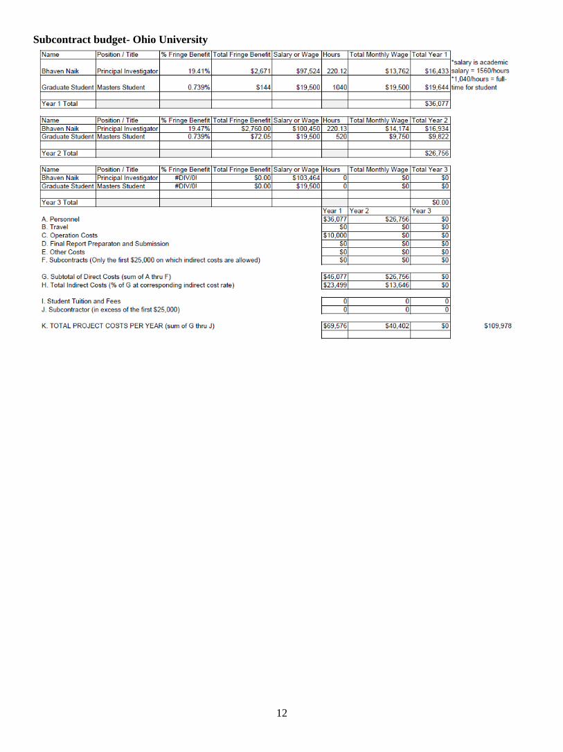
Subcontract budget- Ohio University

13
10. APPENDIX A: EXTENDED LITERATURE REVIEW
As intersection related traffic crashes represent approximately 50% of total traffic crashes, geometric
modifications to existing intersections are explored over the years by traffic engineers and researchers.
Conversion of traditional intersections (i.e., two- and all-way stop control and signalized) to roundabouts has been
a growing practice in many countries around the world, including the U.S. – largely due to the benefits in terms
of reduction in crash frequency and severity, and capacity and operational improvement. A study by the Federal
Highway Administration (FHWA) reported that a roundabout reduces intersection fatality by 90%, injury by 76%,
and crash frequency by 35% in comparison to a traditional intersection (8). While most people are opposed to
roundabouts before implementation, the acceptance increases substantially after installation over time as drivers
become knowledgeable on navigating roundabouts (9). The use of roundabouts is a proven safety strategy for
improving intersection safety by eliminating or altering conflict types, reducing crash severity, and causing
drivers to reduce speeds as they proceed into and through intersections (14). Converting a traditional at-grade
signalized intersection to a modern roundabout is expected to reduce the number of injury crashes by 78 percent,
and converting a traditional two-way stop control intersection to a modern roundabout is expected to reduce the
number of injury crashes by 82 percent (46). According to Kittleson & Associates database, as of 2020, there are
4,963 (71%) single-lane and 1,826 (26%) multi-lane roundabouts in the US (10). Though the number of multi-
lane roundabouts in the US is currently less than half of single-lane roundabouts, multi-lane roundabouts have a
huge potential for the future due to high traffic flow capacity. The FHWA Roundabout Guide (NCHRP 672) has
estimated that a multi-lane roundabout can operate up to 45,000 entering vehicles per day (14), and reduces
congestion and delay (11). However, multi-lane roundabouts have several operational challenges: driver
perceptions about the roundabout, proper lane choice decisions due to driver confusion, striping and signing
issues, bicycle and pedestrian concerns, and ADA (Americans with Disabilities Act) compliance, and traffic
safety due to frequency of traffic crashes (11). In a multi-lane roundabout, drivers are often confused about lane
choice to correctly navigate the roundabout, which leads to two major crash types associated with yielding to the
traffic within the roundabout, and changing lanes within the multi-lane (i.e., making a right turn from the left lane
or making a left turn or U-turn from the right lane) (11).
The emerging turbo roundabouts concept has the potential to reduce the limitations of multi-lane roundabouts.
Turbo roundabout can effectively guide driver behavior within roundabout by limiting lane-changing and
reducing associated lane-change related conflicts, which are common in multi-lane roundabouts (2). Turbo
roundabout was first designed and implemented in the Netherlands in the 1990s (4). Figure A.1 shows a turbo
roundabout from Delft, Netherland (47). It has the same general operating characteristics as modern roundabouts
but utilizes different geometrics and applications of traffic control devices (2). This literature review describes
the characteristics of turbo roundabouts, highlights the design and traffic control features, operational capabilities,
and potential safety benefits of these roundabout alternatives.
Figure A.1: A turbo roundabout in Delft, Netherland (image from Google Maps) (47)

14
Turbo Roundabout Characteristics
Turbo roundabouts possess distinct characteristics compared to modern multi-lane roundabouts. According to
Fortuijn (the inventor of turbo roundabout), the key features of turbo roundabouts are explained and illustrated in
Figure A.2 (13):
Figure A.2: Turbo roundabout key features based on Fortuijn, 2009 (2)
Different Types of Turbo Roundabout
Different types of turbo roundabout can be identified based on a variable number of lanes on the access and exit
legs. A four-legged turbo roundabout may have five variations (illustrated in Figure A.3)- (a) basic, (b) egg, (c)
knee, (d) spiral, and (e) rotor. “Egg” turbo roundabout is similar to “basic” turbo roundabout, except the minor
approaches consist of only one lane. An inside lane is only added on one approach in a “knee” turbo roundabout.
“Spiral” turbo roundabout has three circulatory lanes with inside lane only added on two approaches. Two
approaches consist of three lanes, and two approaches consist of two lanes in a “spiral” turbo roundabout. “Rotor”
type also has three circulatory lanes with an inside lane added on each approach. All approaches consist of three
lanes for “spiral” turbo roundabout (2).
(a) (b)

15
(c) (d)
(e)
Figure A.3: Different types of turbo roundabouts with capacity (2)
Advantages of Turbo Roundabout
The main advantage of turbo roundabouts is safety improvement due to a decrease in conflict points in turbo
roundabouts compared to traditional roundabouts. Figure A.4 illustrates conflict points for two-lane traditional
roundabout and turbo roundabout. Lane barrier between circular lanes in turbo roundabout keeps vehicles in the
same lane (to be selected by drivers before entering the roundabout). It prevents weaving maneuvers (lane-
changing within turbo roundabout) causes sideswipe collisions in a traditional roundabout. A study on 7
intersections (including intersections with yield control, intersections with traffic lights, and an old-style rotary)
that were converted into turbo roundabouts in the period 2000–2002 in the Netherlands observed an 82%
reduction in the accident rate (4). Another advantage of the turbo roundabout is that the traffic flow on lanes can
be much more balanced within the turbo roundabout (4).
(a) (b)
Figure A.4: Conflict points for a two-lane modern roundabout and a turbo roundabout (2)

16
User Considerations in Turbo Roundabout Design
The accommodation of different user groups (i.e., motorists, pedestrians, bicyclists, motorcyclists, and
freight/large vehicles) at turbo roundabouts are discussed in this section.
Motorists
Turbo roundabouts guide the motorists in advance before entering the intersection to choose the assigned lane for
a right turn, through movement, left turn, and U-turn by entry geometry, enhanced delineation of lanes, and proper
road marking and signage. Drivers are required to identify acceptable gaps in no more than two conflicting lanes
at the entrance to a turbo roundabout. A roundabout directional arrow sign is placed directly in the drivers’ field
of view, which directs drivers to enter the circulatory roadway in the appropriate direction (2). These signs
increase the conspicuity of the central island and communicate to drivers about the need to slow down to go
through the roundabout (4). The Roundabouts Informational Guide (NCHRP 672) also recommends using
landscaping to increase central island conspicuity (14). One difference between modern roundabouts and turbo
roundabouts is that vehicles can make U-turn from all approaches in a modern roundabout, but not in a turbo
roundabout. The approaches and lanes from which vehicles can or cannot perform U-turns vary based on the turbo
roundabout types. In Figure 3a, vehicles entering from the inside lane of the east and west approaches (i.e., major
road approaches) can complete a U-turn, while vehicles approaching from the north and south approaches (i.e.,
minor road approaches) cannot complete a U-turn. Thus, it is important to consider the frequency of U-turn
maneuvers at an intersection when evaluating turbo roundabouts as a potential alternative (2).
Pedestrians
The navigation of pedestrians through a turbo roundabout is similar to single-lane and multilane roundabouts.
The guidelines from NCHRP Report 834 can be followed in this regard, which are summarized below (2, 14, 15):
1. Keep sidewalks along the perimeter of the roundabout, separated from the edge of the circulatory roadway
with a landscaped strip or buffer.
2. Where crosswalks are provided, locate them for pedestrian convenience and safety, where drivers can be
expected to yield the right-of-way, and where the crossing will be less likely to be blocked by queued
vehicles.
3. Provide a splitter island sufficiently wide to accommodate a pedestrian crossing that is accessible to
pedestrians with disabilities as well as wide enough for comfortable queueing.
Bicyclists
Bicycle features at turbo roundabouts are not different from traditional roundabouts. The decision of whether to
add separated bicycle facilities at turbo roundabouts depends on factors such as bicycle volume, the presence of
existing bicycle facilities, traffic volume, the complexity of the roundabout, adjacent infrastructure, land use, and
right-of-way availability. The following factors can be considered to accommodate bicyclists at a turbo
roundabout (2, 14):
1. Keeping turbo roundabout radius small to reduce vehicle speeds, which can make bicyclists more
comfortable.
2. Terminating bicycle lanes before the edge of the circular way and crosswalks with enough length
remaining for bicyclists to merge into traffic.
3. Introducing bicycle lanes on exit legs downstream of crosswalks.
4. If bicyclists share the sidewalk, designing sidewalks to meet shared use path width requirements.
5. If the intent is for bicyclists to cross at-grade on approaches, whether on a designated crossing or on a
pedestrian crosswalk, a pavement-level cut-through of the splitter island can be provided. The cut-through
can be designed to include a chicane to encourage a two-stage crossing for bicyclists and provide more
time for approaching drivers to identify crossing bicyclists. This is a commonly used treatment in
Netherlands.
Motorcyclists
Between 2005 and 2013, a total of 46 fatal crashes were known to have occurred at roundabouts in the U.S. and
among those 21 involved a motorcycle (49). Motorcycle safety at roundabouts can be impacted by the presence

17
of raised lane dividers and curbing, surface friction, pavement markings, drainage, sight distance (especially rider
conspicuity), radius, the roadside environment, and surface conditions. Specific concerns for motorcyclists in
turbo roundabouts are the raised truck apron and lane divider. Sloped curbing with minimal vertical reveal can be
provided for a safer environment for motorcycles compared to vertical or rolled curbing. Supplemental signage
alerting motorcyclists to these elements of turbo roundabouts can also be provided (2).
Freight/Large Trucks
As vehicles aren’t allowed to change lanes within a turbo roundabout, it is critical to provide sufficient space for
large vehicles to complete the movements/turning. In European design guidelines for turbo roundabouts, the
dimension of the design vehicle is considered so that the design vehicle does not track into adjacent lanes (16),
which are not sufficient in the U.S. as trucks are larger in the U.S. compared to Europe. Various design guidelines
for multilane roundabouts in the U.S., such as NCHRP 672 (14), Washington State Department of Transportation
Design Manual (50), and South Carolina Department of Transportation (51), allows large trucks to use the whole
width of the circulatory roadway to negotiate the roundabout. A raised lane divider is not a practical option due
to repeated strikes by the larger vehicles. Agencies can allow design vehicles to track across multiple lanes within
turbo roundabouts to avoid this problem. Large trucks entering the inside lane of turbo roundabout from an
approach need a wider opening to accommodate their larger swept paths. When a raised lane divider option is
used, a traversable, demarcating feature can be provided at the origin of the raised divider to ease the entrance of
larger vehicles (2). A central truck apron is provided in turbo roundabouts to help larger vehicles to navigate the
intersection. Aprons can also be provided on the perimeter of the turbo roundabout to provide more turning space
for large vehicles (2).
Location Considerations
Site characteristics that can influence the feasibility of a turbo roundabout alternative include right-of-way
limitations, intersection skewness, winter maintenance needs, adjacent traffic generators or sites that require pre-
emption, and downstream bottlenecks. Additional detail on this matter can be found in the NCHRP Report 672
(14). Turbo roundabouts may be considered at an intersection where traffic demand indicates the need for a
multilane roundabout (2).
Design Considerations
The geometric design of a turbo roundabout depends on the desired capacity and the desired characteristics of a
design vehicle’s horizontal swept path. The projected demand and the approach roadway cross-sections determine
the number of lanes/lane arrangement, which dictate the type of turbo roundabout to be built. After selecting the
type, a horizontal swept path analysis of the design vehicle is done to decide on lane width and other lane width-
related considerations (e.g., right-of-way, considerations for all vehicle types and users). The turbo roundabout
type and lane widths are combined to construct the turbo block, which guides the geometric design of the
circulatory roadway (2).
Horizontal Design
Turbo Block: The spiral alignment of a turbo roundabout is generated from the “turbo block,” which is a series
of circular arcs with centers located at various points along a reference line known as a “translation axis.” The
turbo block consists of arcs, which represent the inner and outer edges of each lane. The inner radius of the turbo
block represents the radius of the central island, and it is selected based on the anticipated size of the turbo
roundabout. The shift along the translation axis from the center is the width of the lane represented by the arc.
The turbo block and angle of the translation axis differ for each turbo roundabout type. Figure A.5 is a sample
turbo block for a basic turbo roundabout with the major roadway oriented in the East-West direction.

18
Figure A.5: Sample turbo block for a basic turbo roundabout (2)
The turbo block is defined by the characteristics shown in Figure A.5. The center point (CG) is the intersection
of the approach centerlines. The orientation of the translation axis is defined in relation to the major road
approaches. Assuming the major road is oriented in East-West direction (i.e., x-axis) in Figure A.5, the right side
of the translation axis is rotated 57.5 degrees around the center below the x-axis for a four-leg intersection, and
the left side of the translation axis is rotated 65 degrees around the center below the x-axis for a three-leg
intersection (2, 4, 24). The angle of rotation for the translation axis can be adjusted to provide smooth, spiraled
vehicle paths for all vehicle movements. TR1, TR2, TR3, and TR4 are the radius of the circles. TR1 is the radius
of the inside edge of the inside roadway. TR2 is the outside edge of the inside roadway; with the difference
between TR2 and TR1 equal to the width of the inside travel lane plus additional width for the edge lines
delineating the raised lane divider. TR3 is the inside edge of the outside roadway. The difference between TR2
and TR3 is the width of the lane divider. TR4 is the outer edge of the outside roadway.
Another important key set of dimensions defining the turbo block is the distances between the center points of
the arcs. The circles corresponding to the four radiuses are split along the translation axis, and the resulting arcs
are slide along the translation axis in opposing directions by half the distance defined as the shift. The shift is the
distance between the centers of the arcs. The shift can differ for the TR1 centers and the TR2, TR3, and TR4
centers if the inside roadway width is different than the outside roadway width. The shift for the TR1 centers (Δʋ
in Figure A.5) is equal to the difference between the inside edge of the inside roadway and the inside edge of the
outside roadway (also the difference between the values used for TR3 and TR1). The shift for the TR1 centers is
achieved by sliding the two arcs defined by TR1 in opposing directions away from CG, each by Δʋ/2. Based on
the international practice, Δʋ/2 ranges from between 8.5 and 9.5 feet (for total shifts ranging between 17 and 19
feet), as shown in Figure A.5. The shift for the TR2, TR3, and TR4 centers (Δu in Figure A.5) is the distance
between the outside edge of the inside roadway and the outside edge of the outside roadway (also the difference
between the values used for TR4 and TR2). The shift for the TR2, TR3, and TR4 centers is achieved by sliding
the arcs defined by TR2, TR3, and TR4 in opposing directions away from CG by Δu/2, as shown in Figure A.5.
This value (Δu/2) typically ranges from between 7.5 and 8.5 feet (for a total shift of 15 to 17 feet). If the inside
and outside roadways have the same width, the shift value for all radii are the same (i.e., Δʋ = Δu). Internationally,

19
the radius (TR1, TR2, TR3, and TR4) for basic turbo roundabouts have ranged as follows:34 to 66 feet for TR1;
52 to 82 feet for TR2; 53 to 83 feet for TR3; and 70 to 100 feet for TR4. The nominal diameter of the turbo
roundabout is twice the value TR4 plus the width of the TR2/3/4 shift, Δu. Assuming a shift of 15 feet, the
inscribed circle for basic turbo roundabouts ranges from 155 feet to 215 feet.
Lane and Roadway Width: The width of each lane of a turbo roundabout is determined by a horizontal swept path
analysis of the design vehicle. The inside lane is often wider than the outside lane to compensate for the design
vehicle maneuvering a smaller radius. Inside lane width ranges from between 14 and 16 feet, while outside lane
width ranges from between 13 and 14.5 feet. The inner roadway width (TR2-TR1), including the inside and
outside edge line pavement markings, ranges from between 16 and 18 feet. The outer roadway width (TR4 -TR3),
including the inside and outside edge line pavement markings, ranges from between 15 and 16.5 feet (2, 4, 24).
Central Island: The central island is the innermost radius of the turbo block (TR1) and consists of a traversable
portion (i.e., mountable apron) and a non-traversable portion. The non-traversable portion is typically used for
signage. Cutouts are provided in the central island to introduce the inside lane of the turbo roundabout on the
applicable approaches. These cutouts can be curved or flat. Objects placed on the central island should not restrict
sight distance along the circulatory roadway (2).
Lane Divider: Lane divider between each circulating lane is an important feature of the turbo roundabout. It can
be of two types- raised and not raised. A raised lane divider is often introduced with a traversable, demarcating
feature to allow turning by large trucks. Turbo roundabouts without raised lane dividers are implemented to
facilitate motorcyclists and snow plowing operations (4). Alternatives to the raised lane divider include striping
and colorized or textured pavement, milled rumble strips or rumble stripes, a double solid white lane (17).
Approach Geometry: Turbo roundabouts are constructed with radial approaches, which reduces the changes to
the alignment along the approach roadway and maintaining exit curvature that encourages drivers to maintain
slower speeds through the exit of the roundabout. Turbo roundabouts are built with little or no flare or deflection
and smaller entry radius. Therefore, the angle between entering traffic and circulating traffic is larger (closer to a
perpendicular entry) for a turbo roundabout than for other multilane roundabouts. This approach geometry is
based on the premise that it will be clear to drivers that they are approaching an intersection that should be
negotiated at lower speeds (4). Potential disadvantages include drivers errantly hitting the central island, making
wrong-way left turn maneuvers to enter the roundabout, and making wrong-way exit maneuvers into entrance
approach lanes (14). Published literature emphasizes the importance of a roundabout directional arrow sign,
placed in the central island in the line of sight of approaching drivers, that directs drivers to turn right and increases
the conspicuity of the central island and the need for a forgiving design of the central island and sign in the case
that either is struck (2). Turbo roundabout entry radius ranges from 39 to 50 feet (16, 24) while the multilane
roundabouts in the US are designed with entry radius exceeding 65 feet, and even single-lane roundabouts have
entry radii ranging from 50 to 100 feet (14).
Sight Distance and Visibility
Adequate stopping and decision sight distance should be provided for all users at all approaches of the turbo
roundabout. NCHRP Report 672 provides guidelines for evaluating sight distance and visibility at roundabouts
(14).
Signage and Pavement Markings
Signage and pavement markings on the approaches, especially for lane selection, are critical for motorists to
identify and select their desired lane before entering the turbo roundabout. MUTCD and NCHRP Report 672,
describe applications of lane control signage for roundabout approaches (14, 17). Lane control signage can be
supplemented using pavement marking arrows (2). Signage can also direct pedestrians and bicyclists to designated
facilities, drivers to their desired lanes, and communicate the presence of raised curbing, such as a raised lane
divider (if one is used). If the lane divider includes grooved, textured, or brick pavements, consideration can be
given to including sign W8-15 to warn road users of its presence. Pavement markings shall be used to delineate
the edges of the approach and circulatory lanes. Additionally, supplemental delineation can be achieved using
reflectors or light-emitting diodes (LEDs) to illuminate the edges of the apron and lane dividers (2, 17).
Pedestrian Design Treatments
Pedestrian accommodations in turbo roundabouts are similar to modern roundabouts. Crossings should be kept at
the perimeter of the intersection, with crosswalks and splitter islands on the approaches to facilitate two-stage

20
crossings. All sidewalks, crosswalks, and curb ramps should be accessible to and usable by pedestrians with
disabilities for ADA compliance. The crosswalk should be placed far enough (minimum of 20 feet, or one vehicle-
length) from the circulatory roadway so that a motorist can exit the roundabout and then stop before reaching any
potential pedestrians in the crosswalk (2, 14).
Bicycle Design Treatments
Bicycle guidance for turbo roundabouts is also the same as for modern roundabouts. A bicyclist can either mix
with motor vehicle traffic or, when available, utilize separated facilities based on the bicyclist volume, traffic
volume, complexity of the roundabout, adjacent infrastructure, land use, and available right-of-way. In the
Netherlands, separate bicycle paths outside of the roundabout are recommended for turbo roundabouts where
possible (2, 24).
Vertical Design
Vertical alignment considerations in turbo roundabouts are the same as modern roundabouts. The geometry
should not restrict sight distance throughout the intersection area, including decision sight distance on the
approaches when selecting lanes, stopping sight distance on the approach and on the circulatory roadway, and
intersection sight distance at the entrances to the circulatory roadway (2).
Lighting
The proper lighting should be done to improve the visibility of the middle island and raised lane divider (24).
Lighting should also be provided to give adequate visibility for pedestrian and bicycle facilities, especially
crossings, and negative contrast lighting and shadowing should be avoided (2,15).
Landscaping
Landscaping should be limited to the non-traversable portion of the central island and not blocking the stopping
sight distance around the circulatory roadway. If sprinklers are used to maintain landscaping, designers should
consider the impacts of irrigation runoff onto the circular roadway, as unexpected wet pavement can introduce
another potential safety risk to users of the intersection (2, 52).
Other Design Considerations
Additional design considerations, such as bypass lanes, access management, at-grade rail crossings, evacuation
routes, and bus stops, should be addressed the same as they are for modern roundabouts. Specific guidelines for
these issues can be found in NCHRP Report 672 (2, 14).
Comparison to United States Roundabout Design Principles
NCHRP Report 672 describes six overarching principles that inform the design of roundabouts (14). Table A.1
describes the principles and the manners in which they are addressed in turbo roundabouts (2).
Table A.1: Roundabout design principles compared with turbo roundabout (2)
Design Principles from NCHRP Report
672 (14)
Addressed in Turbo Roundabouts
“Provide slow entry speeds and consistent
speeds through the roundabout by using
deflection.”
International practices of a perpendicular entry and smaller
radii of the right turns on entry are intended for slow vehicle
entry speeds.
“Provide the appropriate number of lanes
and lane assignment to achieve adequate
capacity, lane volume balance, and lane
continuity.”
Turbo roundabout variants are available for a range of
traffic demand. International research suggests basic turbo
roundabouts have similar capacities as multilane
roundabouts with two entry and two circulating lanes.
“Provide smooth channelization that is
intuitive to drivers and results in vehicles
naturally using the intended lanes.”
The spiral lane markings and lane dividers provide intuitive
messaging to drivers on lane selection, lane-keeping, and
the appropriate maneuvers from each lane.
“Provide adequate accommodation for
design vehicles.”
As with modern multilane roundabouts, lane width
decisions for turbo roundabouts are informed by a
horizontal swept path analysis of the design vehicle along
with other lane width-related considerations (e.g., right-of-
way, performance for all vehicle types and users).

21
Additionally, aprons are provided on the central island and,
as necessary, on the perimeter of the roundabout to provide
additional space.
“Design to meet the needs of pedestrians
and cyclists.”
Pedestrian and bicycle accommodations for turbo
roundabouts do not differ from modern multilane
roundabouts.
“Provide appropriate sight distance and
visibility for driver recognition of the
intersection and conflicting users.”
Signage is placed far enough in advance of the roundabout,
so road users are aware of the approaching intersection and
the need to select their appropriate lane before entering the
roundabout. The roundabout directional arrow sign on the
central island increases driver recognition of the
roundabout.
Safety Performance of Turbo Roundabout
As turbo roundabouts are still an emerging concept, international safety studies based on an analysis of crash data
are limited and not yet available based on any installation in the US. Seven intersections, including signalized,
yield-control, and old-style rotary types, were converted to a turbo roundabout in the Netherlands and found an
82% percent reduction in the number of injury crashes (4). A Polish research found that turbo roundabouts with
a raised lane divider experience a lower crash frequency than those with paint stripes only, and in both cases the
researchers observed lower severity crash outcomes (18). Surrogate safety measures based on microscopic traffic
simulations (e.g., time-to-collision, vehicle speeds, vehicle conflicts, incorrect movements, and incorrect paths)
have also indicated that turbo roundabouts are likely to experience less frequent and less severe crashes than
multilane roundabouts due to the fewer conflict points within the roundabout and the lower speeds required to
navigate the smaller radius (19, 20, 21, 22, 23).
Table A.2. The conclusions from international scientific researches on road safety on turbo roundabouts
(18).
Country Findings
Holland The risk of injury following a road traffic accident or collision on turbo roundabouts
is 80% lower than in other types of multi-lane roundabouts. A slightly lower reduction
of the injury risk on turbo roundabout (by 70%) is expected compared to single-lane
roundabouts.
Turbo roundabouts are 70% safer than intersections without traffic signals, 50% safer
than intersections with traffic signals.
Italy A degree of improvement in road safety on the turbo roundabouts depends on the
traffic organization, intensity, and directional structure of traffic and ranges from 40 to
50% reduction in traffic accidents.
After the reconstruction of three intersections into turbo roundabouts, road safety
conditions improved while driving speed reduced considerably.
Slovenia No traffic accidents with serious consequences were recorded (analysis was carried out
in one location).
Slovakia Turbo roundabouts are characterized as a solution with a very high level of safety
improvement.
Colombia Turbo roundabouts exhibit improvement in road safety by 22%.
Poland
After the reconstruction of the roundabout into a turbo roundabout (with lane dividers
in the form of a single continuous line), the number of collisions was declined by 80%.

22
• In general, high level of road safety was recorded at intersections. No fatalities were
reported during the period of the analysis. Property damage only (PDO) was
predominant (95.98%) among the recorded traffic accidents.
• The most frequent traffic accidents were rear-end collisions, driving into an
obstacle, side-impacts, and overturning.
• The most frequent causes of the traffic events were not-giving way, the excessive
speed with respect to the conditions on the road, lack of safe distance from the
preceding vehicle, illegally changed lanes, and illegal overtaking.
In Portugal, the first turbo roundabout was built in Coimbra (Choupal Rbt), replacing an existing single-lane
roundabout (19). Before implementation, a study was conducted to evaluate the safety and operational
performance of the prospective turbo roundabout to be constructed. For comparison, three layouts of similar
implantation areas were modeled in Aimsun – the existing single-lane solution, a two-lane alternative, and a turbo-
roundabout. All three models were simulated with the current traffic demand (23816 veh/d). The safety analysis
was done by SSAM, and the results presented in Table A.3, and the layouts of the three models with SSAM results
are shown in Figure A.6. The two-lane roundabout showed the worst performance both in the number and severity
of conflicts, mostly due to the weaving maneuvers. The turbo-roundabout, compared with the single-lane solution,
had fewer conflicts, but these are more severe due to the increased angle between entry and circulating trajectories.
Turbo roundabout performed better than tow-lane roundabout in terms of safety performance.
Figure A.6. SSAM results for the Choupal Rbt: graphical display of conflicts, colored by relative speed as
the proxy for the accident severity (19).
Table A.3. SSAM results for the Choupal Rbt, Coimbra, Portugal (19) Roundabout type (conflicts/day) Relative speed (m/s)
< 5 5 - 10 > 10
Single-lane roundabout 420 46% 44% 10%
Two-lane roundabout 539 49% 37% 14%
Turbo roundabout 301 51% 36% 13%

23
Another study on turbo roundabout safety analysis was performed using the VISSIM microsimulation model of
a two-lane roundabout in Bogota (20). With the known traffic demand, a basic turbo roundabout was designed,
simulated, and calibrated. Vehicular trajectory files were obtained from calibrated simulation models, which were
analyzed by SSAM to estimate traffic conflicts. The number of conflicts in the two-lane roundabout and the turbo-
roundabout are summarized in Table A.4. The total number of conflicts in the turbo-roundabout was 72% lower
than in the two-lane roundabout.
Table A.4 - Comparison between intersections based on the number of conflicts (20)
Parameter Total Rear-end conflicts Crossing conflicts
Angle Threshold - 0° - 45° 45° - 135°
Two-lane roundabout 338 209 129
Turbo-roundabout 96 44 52
Difference 242 165 77
Change -72% -79% -60%
Operational Performance of Turbo Roundabout
Like modern roundabouts, turbo roundabout capacity is measured at the approach level. International studies
suggest that basic turbo roundabouts have similar capacities as multilane roundabouts with two entry and two
circulating lanes. One study in the Netherlands estimated a capacity for a basic turbo roundabout design of
approximately 3,500 pc/h for all entries combined, assuming conflicting traffic volumes between 1,900 and 2,100
pc/h (24). Turbo roundabout exhibits lower speeds than a two-lane roundabout and lower speed than a single lane
roundabout with an inner radius less than 15 meters (Figure A.7).
Figure A.7: Speed comparison between types of the roundabout with a splitter island width of 7 m (24)
For estimating turbo roundabout capacity, gap-acceptance models that consider critical headway, critical follow-
up time, and conflicting traffic appear to be adequate. A study in Poland found the Highway Capacity Manual
(HCM) capacity models for roundabouts produced capacity estimates for Polish turbo roundabouts with
reasonable accuracy (25). Therefore, the roundabout capacity models of the HCM are likely to represent
reasonable capacity estimates for turbo roundabout approaches with up to two lanes (2).
Costs
As of today, no turbo roundabouts have been constructed in the US. As turbo roundabouts are similar to multilane
roundabouts, they are expected to have similar types of costs. Turbo roundabouts may vary slightly from multilane
roundabouts in the required right-of-way. A radial entry with no flare and smaller entrance radius requires a larger
swept path for large vehicles, which will lead to a wider circular roadway than for a comparable multilane
roundabout. However, there may not be significant changes to the alignment of the approach roadway given the
entry geometry of the turbo roundabout (2).

24
11. REFERENCES
1. Leuer, D. (2016). Examining Multilane Roundabouts in Minnesota. Minnesota Department of
Transportation. St. Paul, Minnesota.
2. Federal Highway Administration. (2019). Turbo Roundabouts: Informational Primer. Federal Highway
Administration, Report No. FHWA-SA-20-019, Washington, D.C.
https://safety.fhwa.dot.gov/intersection/innovative/roundabouts/docs/fhwasa20019.pdf
3. Engelsman, J. C., & Uken, M. (2007). Turbo roundabouts as an alternative to two lane roundabouts. SATC
2007.
4. Fortuijn, L. G. (2009). Turbo roundabouts: Design principles and safety performance. Transportation
Research Record, 2096(1), 16-24.
5. DeBaan, Dirk, March 2017, (SWOV: R-2014-21) Safety Presentation to the Author - Turbo roundabouts’
safety impacts compared to multi-lane roundabouts, Rotterdam, The Netherlands.
6. Turbo Roundabout Design Guidelines Translated to the USA Bill Baranowski, President of Roundabouts
USA, Salt Lake City, UT. Email: [email protected].
7. Choi, E. (2010). Crash Factors in Intersection-Related Crashes: An On-Scene Perspective. National
Highway Traffic Safety Administration, Report No. DOT HS 811 366, Washington, D.C.
https://crashstats.nhtsa.dot.gov/Api/Public/ViewPublication/811366
8. Persaud, B. N., Retting, R. A., Garder, P. E., & Lord, D. (2001). Safety Effect of Roundabout Conversions
in the United States: Empirical Bayes Observational Before-After Study. Transportation Research Record,
1751(1), 1–8. https://doi.org/10.3141/1751-01
9. Hu, W., McCartt, A. T., Jermakian, J. S., & Mandavilli, S. (2014). Public opinion, traffic performance,
the environment, and safety after construction of double-lane roundabouts. Transportation research record,
2402(1), 47-55.
10. Kittleson & Associates,. Inc. https://roundabouts.kittelson.com/Home/PBIReports
11. Leuer, D. (2016). Examining Multilane Roundabouts in Minnesota. Minnesota Department of
Transportation. St. Paul, Minnesota.
12. Federal Highway Administration. (2019). Turbo Roundabouts: Informational Primer. Federal Highway
Administration, Report No. FHWA-SA-20-019, Washington, D.C.
https://safety.fhwa.dot.gov/intersection/innovative/roundabouts/docs/fhwasa20019.pdf
13. Fortuijn, L. G. (2009). Turbo roundabouts: Design principles and safety performance. Transportation
Research Record, 2096(1), 16-24.
14. Rodegerdts, L., Bansen, J., Tiesler, C., Knudsen, J., Myers, E., Johnson, M., & O’Brien, A. (2010).
Roundabouts: An Informational Guide. NCHRP Report 672. Transportation Research Board-National
Research Council, Washington, DC, USA.
15. Schroeder, B., Rodegerdts, L., Jenior, P., Myers, E., Cunningham, C., Salamati, K., ... & Bentzen, B. L.
B. (2016). Crossing Solutions at Roundabouts and Channelized Turn Lanes for Pedestrians with Vision
Disabilities: A Guidebook (No. Project 03-78B).
16. Džambas, T., Ahac, S., & Dragčević, V. (2017). Geometric design of turbo roundabouts. Tehnički vjesnik,
24(1), 309-318.
17. Federal Highway Administration. (2012). Manual on Uniform Traffic Control Devices for Streets and
Highways, 2009 Edition Including Revision 1 and Revision 2, dated May 2012. Federal Highway
Administration, Washington, D.C. https://mutcd.fhwa.dot.gov/pdfs/2009r1r2/mutcd2009r1r2edition.pdf ,
Accessed December 14, 2020.
18. Macioszek, E. (2015). The road safety at turbo roundabouts in Poland. Archives of Transport, 33.
19. Vasconcelos, L., Silva, A. B., & Seco, A. (2013, May). Safety analysis of turbo-roundabouts using the
SSAM technique. In CITTA 6th Annual Conference on Planning Research (pp. 1-15).
20. Bulla-Cruz, L. and Barrera, L. (2016). Road safety assessment of a two-lane roundabout and a basic turbo-
roundabout using microsimulation of traffic conflicts and analysis of surrogate measures by clusters and

25
principal components*. XIX Congreso Panamericano de Ingeniería de Tránsito, Transporte y Logística -
PANAM 2016, At Ciudad de México.
21. Mauro, R., Cattani, M., & Guerrieri, M. (2015). Evaluation of the Safety Performance of Turbo
Roundabouts by Means of a Potential Accident Rate Mode. The Baltic Journal of Road and Bridge
Engineering, 10(1), 28-38.
22. Chodur, J., & Bąk, R. (2016). Study of driver behaviour at turbo-roundabouts. Archives of transport,
38(2), 17-28.
23. Kieć, M., Ambros, J., Bąk, R., & Gogolín, O. (2019). Evaluation of safety effect of turbo-roundabout lane
dividers using floating car data and video observation. Accident Analysis & Prevention, 125, 302-310.
24. Overkamp, D. P., & van der Wijk, W. (2009). Roundabouts-Application and design, A practical manual,
Royal Haskoning DHV. Ministry of Transport. Public Works and Water management, Partners for Roads.
25. Macioszek, E. (2016). The application of HCM 2010 in the determination of capacity of traffic lanes at
turbo roundabout entries. Transport Problems, 11.
26. Appiah, J., et al., (2011) Development of a State of the Art Traffic Microsimulation Model for Nebraska.
27. Gettman, D., Pu, L., Sayed, T., Shelby, S., & Siemens, I. T. S. (2008). Surrogate safety assessment model
and validation (No. FHWA-HRT-08-051). United States. Federal Highway Administration. Office of
Safety Research and Development.
28. National Highway Traffic Safety Administration. (2019). Welcome to the new NHTSA Query tool.
Washington, D.C. https://cdan.nhtsa.gov/query. Last accessed on December 14, 2020.
29. FHWA (2018) Roundabout Research, FHWA‐HRT‐17‐040, Federal Highway Administration.
Washington, D.C.
30. McKnight, G.A., Khattak, A.J. & Bishu, R. (2008) Driver Characteristics with Knowledge of Correct
Roundabout Negotiation. TRR 2078. pp. 96-99.
31. Shrestha, S. K. (2002) Benefits of Urban Roundabouts in the State of Maryland. In Compendium: Papers
on Advanced Surface Transportation Systems. (No. SWUTC/02/473700-00003-4).
32. Savolainen, P.T., et al. (2012) A Review of Roundabout Public Information and Educational programs
and Materials. In Proceedings of the TRB 91st Annual Meeting, Washington, D.C.
33. Toussant, E.A. (2016) Analyzing the Impacts of Driver Familiarity/Unfamiliarity at Roundabouts.
Master’s Thesis, Department of Civil Engineering, Ohio University.
34. Fisher, D.L., et al. (2011) Handbook of Driving Simulation for Engineering, Medicine, and Psychology.
s.l. : CRC Press.
35. Allen, R.W., Rosenthal, T.J., and Cook, M.L. (2011) A Short History of Driving Simulation.
36. Sahami, S., & Sayed, T. (2013). How Drivers Adapt to Drive in Driving Simulator and What is the Impact
of Practice Scenario on the Research? Transportation Research Part F, pp.41-52.
37. Underwood, G., Crundall, D., and Chapman, P. (2011) Driving Simulator Validation with Hazard
Perception. Transportation Research Part F - Traffic Psychological Behavior, 14(6), pp.435-446.
38. Bobermin, M.P., Silva, M.M., and Ferreira, S. (2021) Driving Simulators to Evaluate Road Geometric
Design Effects on Driver Behaviour: A Systematic Review. Accident Analysis & Prevention, Vol. 150.
39. Calvi, A., and Amico, F.D. (2006) Quality Control of Road Project: Identification and Validation of a
Safety Indicator. International Journal of Advanced Transportation Studies, 9, pp.47-66.
40. Calvi, A. (2015) Does Roadside Vegetation Affect Driving Performance? Driving Simulator Study on the
Effects of Trees on Drivers’ Speed and Lateral Position. TRR 2518, pp.1—8.
41. A. Calvi, F. Bella, F. D’Amico (2018) Evaluating the effects of the number of exit lanes on the diverging
driver performance J. Transp. Saf. Secur., 10 (1–2), pp. 105-123
42. El-Dabaja, S. (2019). Drivers of “Driverless” Vehicles: A Human Factors Study of Connected and
Automated Vehicle Technologies. PhD Dissertation. Ohio University, Athens, Ohio.
43. Campbell, J. (2020). Human Factors Study of Wrong-Way Driving Events. Master’s Thesis. Ohio
University, Athens, Ohio.

26
44. Korber, M. et al. (2016). The Influence of Age on the Take-Over of Vehicle Control in Highly Automated
Driving. Transportation Research Part F: Traffic Psychology and Behavior, pp.19-32.
45. Salvia, E. et al. (2016). Effects of Age and Task Load on Drivers' Response Accuracy and Reaction Time
when Responding to Traffic Lights. Frontiers in Aging Neuroscience.
46. Rodegerdts, L. (2007). Roundabouts in the United States (Vol. 572). Transportation Research Board.
47. “A turbo roundabout in Delft, Netherland” Photograph. Google Maps. Accessed December 16, 2020.
https://www.google.com/maps/@51.9661947,4.4582251,222m/data=!3m1!1e3.
48. Vasconcelos, L., Silva, A. B., Seco, Á. M., Fernandes, P., & Coelho, M. C. (2014). Turboroundabouts:
multicriterion assessment of intersection capacity, safety, and emissions. Transportation research record,
2402(1), 28-37.
49. Federal Highway Administration. (2015). A Review of Fatal and Severe Injury Crashes at Roundabouts.
Federal Highway Administration, Publication No. FHWA-SA-15-072, Washington, D.C.
50. Washington State Department of Transportation. (2019) Design Manual, M 22-01.17, September 2019.
Washington State Department of Transportation, Olympia, Washington. Retrieved from:
https://www.wsdot.wa.gov/publications/manuals/fulltext/M22-01/design.pdf.
51. South Carolina Department of Transportation. (2017). South Carolina Roadway Design Manual, March
2017. South Carolina Department of Transportation, Columbia, South Carolina. Retrieved from:
https://www.scdot.org/business/pdf/roadway/2017_SCDOT_Roadway_Design_Manual.pdf.
52. Milling, D., Affum, J., Chong, L., & Taylor, S. (2016). Infrastructure improvements to reduce motorcycle
casualties (No. AP-R515-16).

27
12. APPENDIX B: CVs
Kakan Chandra Dey, PhD, PE
Assistant Professor
Department of Civil and Environmental Engineering
West Virginia University, Morgantown, WV 26506
Tel: 304-293-9952, Email: [email protected]
EDUCATION
▪ Doctor of Philosophy in Civil Engineering, May 2014
Clemson University, South Carolina; Emphasis: Transportation Systems
▪ Master of Science in Civil Engineering, May 2010
Wayne State University (WSU), Michigan; Emphasis: Transportation
Engineering
▪ Bachelor of Science in Civil Engineering, June 2005
Bangladesh University of Engineering & Technology (BUET), Bangladesh
PROFESSIONAL LICENSE
Professional Engineer, 2018-
West Virginia State Board of Registration for Professional Engineers
APPOINTMENTS
▪ Assistant Professor (August 2016- Present)
Department of Civil and Environmental Engineering
West Virginia University, WV
▪ Project Manager, NSF US Ignite Project (January 2016 – August 2016)
Clemson University, Clemson, SC
▪ Postdoctoral Fellow (May 2014 – August 2016)
Connected and Automated Vehicle Technology Group
Glenn Department of Civil Engineering, Clemson University
MAJOR ACHIEVEMENTS
▪ George N. Saridis Best Transactions Paper Award 2017, IEEE Transactions
on Intelligent Transportation Systems
▪ ASCE ExCEEd Teaching Workshop Fellowship 2017
▪ Distinguished Postdoctoral Fellowship award, Clemson University 2016
▪ Two research projects I worked were selected as High Value Research
Project by the AASHTO Research Advisory Committee in 2014 and 2012
RESEARCH INTERESTS
▪ Intelligent Transportation Systems (ITS)
▪ Connected and Autonomous Vehicle Technology
▪ Data Analytics for Connected Transportation Systems
▪ Artificial Intelligence for Connected Vehicle Applications
▪ Cyber-Physical Systems
▪ Sustainability and Resiliency in Transportation

28
▪ Traffic Safety, Traffic Simulation
SELECTED PEER-REVIEWED JOURNAL PUBLICATIONS (Total 903 citations as of
December 29, 2020 Source: Google Scholar) * my graduate students, ** corresponding author
[1] *Ahmed, S., Dey, K.** (2020) Resilience modeling concepts in
transportation systems: a comprehensive review based on mode, and
modeling techniques. Journal of Infrastructure Preservation and
Resilience 1, 8 https://doi.org/10.1186/s43065-020-00008-9
[2] He, Y., *Rahman, M. T., Akin, M., Wang, Y., **Dey, K., and **Shi, X.
(2020). Connected Vehicle Technology for Improved Multimodal Winter
Travel: Agency Perspective and a Conceptual Exploration. Sustainability,
12(12), 5071.
[3] Das, S., Dutta, A., Dey, K., Jalayer, M., and Mudgal, A. (2020) “Vehicle
involvements in hydroplaning crashes: applying interpretable machine
learning,” Transportation research interdisciplinary perspectives, 6,
100176.
[4] *Ahmed, S., Dey, K., and Fries, R., (2019) “Evaluation of Transportation
System Resilience in the Presence of Connected and Automated Vehicles,”
Transportation Research Record, 2673(9), 562-574, 0361198119848702.
[5] Khan, Z., Khan, S. M., Dey, K., and Chowdhury, M. (2019) “Development
and Evaluation of Recurrent Neural Network-Based Models for Hourly
Traffic Volume and Annual Average Daily Traffic
Predictions,” Transportation Research Record, 2673(7), 489-503,
0361198119849059.
[6] Khan, S. M., Mitchell, J., Chowdhury, M., Dey, K., and Huynh, N. (2018)
“Operational analysis of a connected vehicle-supported access control on
urban arterials,” IET Intelligent Transport Systems, 12(2), 134-142.
[7] Rahman, M., Chowdhury, M., Dey, K., Islam, M. R., and Khan, T. (2017),
“Evaluation of Driver Car-Following Behavior Models for Cooperative
Adaptive Cruise Control Systems,” Transportation Research Record:
Journal of the Transportation Research Board, Vol. 2622, 84-95.
[8] Bhavsar, P., Das, P., Paugh, M., Dey, K., and Chowdhury, M. (2017),
“Risk Analysis of Autonomous Vehicles in Mixed Traffic Streams,”
Transportation Research Record: Journal of the Transportation Research
Board, Vol. 2625, 51-61.
[9] Khan, S. M., Dey, K., and Chowdhury, M. (2017), “Real-Time Traffic
State Estimation with Connected Vehicles,” IEEE Transactions on
Intelligent Transportation Systems. Vol 18, Issue 7, 1687 - 1699
[10] Dey, K., Rayamajhi, A., Chowdhury, M., Bhavsar, P., (2016)
“Vehicle-to-Vehicle (V2V) and Vehicle-to-Infrastructure (V2I)
Communication in Heterogeneous Wireless Network - Performance
Evaluation,” Transportation Research Part C: Emerging Technologies,
Vol. 68, 168-184.
[11] Li, Z., Dey, K., Chowdhury, M., and Bhavsar, P., (2016) “Connected
Vehicle Technology Application for Dynamic Routing of Electric Vehicles
in an Inductively Coupled Power Transfer Environment,” IET Intelligent
Transport Systems Journal, DOI# 10.1049/iet-its.2015.0154
[12] Dunning, A., Dey, K., and Chowdhury, M., (2015) “Review of
Transportation Infrastructure Deterioration and Recovery Policies due to
Overweight Truck and a Case Study on Stakeholders’ Perspectives,”
ASCE Journal of Infrastructure Systems. DOI: 10.1061/(ASCE)IS.1943-
555X.000029

29
[13] Dey, K., Yan, L., Wang, X., Wang, Y., Shen, H., Chowdhury, M., Yu,
L., Qiu, C., and Soundararaj, V., (2015) “A Review of Communication,
Driver Characteristics and Controls Aspects of Cooperative Adaptive
Cruise Control (CACC),” IEEE Transactions on Intelligent Transportation
Systems, Published online, DOI: 10.1109/TITS.2015.2483063. Recipient of
the George N. Saridis Best Transactions Paper Award 2020
[14] Dey, K., Chowdhury, M., Wiecek, M., and Dunning, A., (2014)
“Tradeoff Analysis for Offsetting Overweight Truck Damage Costs to
transportation Infrastructure,” ASCE Journal of Transportation
Engineering, Vol. 141(7), 04015008
[15] Dey, K., Chowdhury, M., Pang, W., Putman, B., and Chen, L., (2014)
“Estimation of Pavement and Bridge Damage Costs Due to Overweight
Trucks,” Transportation Research Record, Vol. 2411, pp. 62-71
[16] Davis-McDaniel, C., Chowdhury, M., and Pang, W., and Dey, K.,
(2013) “Fault-tree model for identification of causal factors and risk
assessment of bridge failure,” ASCE Journal of Infrastructure Systems,
Vol. 19(3), pp. 326–334
Under
Review
[1] Rahman, M.T., Dey, K., Martinelli, D.R., and Mishra, S., “Modeling and
Evaluation of a Ridesharing Matching System from Multi-Stakeholders’
Perspective”
[2] Dey, K., Rahman, M.T., Martinelli, D.R., Das, S., and Williams, A.M.,
“Left Turn Phasing Selection Considering Vehicle to Vehicle and Vehicle
to Pedestrian Conflicts”
[3] Rahman, M.T., Dey, K., Das, S, Sherfinski, M., “Sharing the Road with
Autonomous Vehicles: A Qualitative Analysis of the Perceptions of
Pedestrians and Bicyclists”
BOOKS
Chowdhury, M., Apon, A., Dey, K. [Editors], Data Analytics for Intelligent
Transportation Systems, Elsevier, 2017, eBook ISBN: 9780128098516,
Paperback ISBN: 9780128097151
BOOK CHAPTERS
[1] Dey, K., Fries, R., and Ahmed, S. (2018). Future of Transportation Cyber-
Physical Systems–Smart Cities/Regions. In Transportation Cyber-
Physical Systems (pp. 267-307). Elsevier.
[2] Khan, S. M., Ngo, L. B., Morris, E. A., Dey, K., and Zhou, Y. (2017).
Social Media Data in Transportation. In Data Analytics for Intelligent
Transportation Systems (pp. 263-281).
PROJECT REPORTS
[1] Bhavsar, P., Dey, K., Chowdhury, M., and Das, P. (2017) “Risk analysis of
autonomous vehicles in mixed traffic streams,” Final Report University
Transportation Research Center-Region 2, UTRC/RF Grant No: 49198-28-
27
[2] Chowdhury, M., Putman, B., Pang, W., Dunning, A., Dey, K., and Chen,
L., (2013) “Study of rate of deterioration of bridges and pavements as
affected by trucks,” South Carolina Department of Transportation, Final
Report FHWA-SC-13-05. AASHTO Research Advisory Committee
selected “High Value Research Project” in year 2014.

30
[3] Chowdhury, M., Ogle, J., Gowan, B., Tupper, L., Familian, S., and Dey, K.,
(2011) “The Relationship of South Carolina Damage Claims to Roadway
Engineering Safety Issues,” South Carolina Department of Transportation,
Final Report FHWA-SC-11-01. AASHTO Research Advisory Committee
selected “High Value Research Project” in year 2012.
[4] Savolainen, P., Dey, K., Ghosh, I., Karra, T., Lamb, A, (2009)
“Investigation of Emergency Vehicle Crashes in the State of Michigan,”
No. NEXTRANS Project No. 015WY01.
FUNDED PROJECTS (MOST RECENT)
[1] Center for Advanced Multimodal Mobility Solutions and Education
(CAMMSE), “Multimodal Connected Vehicle Pilot for Winter Travel,” in
collaboration with Washington State University, 2020-2021, My role: PI
at WVU
[2] Tennessee Department of Transportation, “Towards Sustainable Tourism
Transportation Systems and Services in Tennessee,” in collaboration with
University of Memphis, 2020-2022, My role: PI at WVU
[3] National Science Foundation, “Research Initiative: A Holistic Cross-
Disciplinary Project Experience as a Platform to Advance the Professional
Formation of Engineers,” 2019-2021, My role: PI
[4] South Dakota Department of Transportation, “Winter Maintenance Levels
of Service and Performance Measures,” 2019-202, My role: PI
[5] Ohio Department of Transportation, “Intersection Modifications Using
Modular Mini-Roundabout Methods,” in collaboration with Ohio
University, 2019-2020, My role: PI at WVU
[6] Tennessee Department of Transportation, “Investigation On Wrong-Way
Prevention Technologies And Systems,” in collaboration with University
of Memphis, 2019-2020, My role: PI at WVU
SELECTED SYNERGISTIC ACTIVITIES
▪ Project Panel member, Behavioral Traffic Safety Cooperative Research
Program, Transportation Research Board (TRB)- National Research
Council, 2019-2022
▪ Advisory Board Member, Center for Multimodal Mobility, USDOT Tier-1
UTC, 2017-2022
▪ Session Chair, “Lest in Truck Size and Weight Research,” In TRB 99th
Annual Meeting, to be held January 14, 2020, Washington, D.C.
▪ Session Chair, “Artificial Intelligence and Machine Learning Methods for
Transportation Applications, Part 1,” In TRB 98th Annual Meeting, to be
held January 14, 2019, Washington, D.C

31
Bhaven Naik, PhD, PE, PTOE, RSP.
Associate Professor
Department of Civil Engineering
Stocker Center 226
1 Ohio University, Athens OH 45701
Phone: +1 (740) 593-4151
Email: [email protected].
PROFESSIONAL PREPARATION
2010 Doctorate. (Civil Eng. – Transportation major + Statistics minor); Univ. of Nebraska,
Lincoln, NE.
2004 Masters. (Civil Eng. – Transportation major); Univ. of Nebraska, Lincoln, NE.
2003 Bachelors. (Civil Eng.); Univ. of Nebraska, Lincoln, NE.
1997 Diploma (Civil Eng.); Copperbelt University, Kitwe, Zambia.
PROFESSIONAL REGISTRATION
Registered Professional Engineer – Nebraska (#E-15635) and Ohio (#PE.81951).
Registered Professional Traffic Operations Engineer (#4065).
Registered Road Safety Professional (#305).
APPOINTMENTS
Ohio University
Associate Professor – Department of Civil Engineering August, 2020 – Present
Assistant Professor – Department of Civil Engineering August, 2014 – August, 2020
University of Nebraska-Lincoln
Lecturer – Department of Civil Engineering January, 2013 – August, 2014
Post-Doctoral Research Associate, Mid-America Transportation Center January, 2011 – August, 2014
PUBLICATIONS AND PRESENTATIONS
Peer Reviewed Journal Papers (2014 to present)
2020
Walubita, L.F., Fuentes, L., Lee, S.I., Guerrero, O., Mahmoud, E., Naik, B., & Simate, G.S. Correlations and
Preliminary Validation of the Laboratory Monotonic Overlay Test Data to Reflective Cracking Performance of
In-Service Field Highway Sections. Journal of Construction and Building Materials, (In Press).
Barbieri, D.M. et al. Survey Data Regarding Perceived Air Quality in Australia, Brazil, China, Ghana, India,
Iran, Italy, Norway, South Africa, United States Before-and-After COVID-19 Restrictions. Data in Brief
Journal, (Accepted for publication, Aug 6, 2020).
El-Dabaja, S., McAvoy, D., & Naik, B. Alert! Automated Vehicle (AV) System Failure – Drivers’ Reactions to
a Sudden, Total Automation Disengagement. In: Stanton, N. (eds) Advances in Human Aspects of
Transportation. AHFE 2020, Advances in Intelligent Systems and Computing, 1212, pp.49-55.
Walubita, L.F., Fuentes, L., Faruk, A.N.M., Komba, J., Prakoso, A., & Naik, B. Mechanistic-Empirical
Compatible Traffic Data Generation: Portable WIM versus Cluster Analysis. Journal of Testing and
Evaluation, 48 (3), pp.2377-2392.
2019

32
Walubita, L.F., Fuentes, L., Prakoso, A., Rico Pianeta, L.M., Komba, J.J., & Naik, B. Correlating the HWTT
Laboratory Test Data to Field Rutting Performance of In-Service Highway Sections. Journal of
Construction and Building Materials, 236, pp.1-12.
Fuentes, L., Camargo, R., Martinez-Arguelles, G., Komba, J.J., Naik, B., & Walubita, L.F. Pavement
Serviceability Evaluation using Whole Body Vibration Techniques: A Case Study for Urban Roads.
International Journal of Pavement Engineering, 20, pp. 1-12.
Naik, B., Appiah, J., & Rilett, L.R. Are Dilemma Zone Protection Systems Useful on High Speed Arterials
with Signal Coordination? A Case Study. International Journal of Intelligent Transportation Systems
Research, pp.1-11.
Walubita, L.F., Faruk, A.N.M., Fuentes, L., Prakoso, A., Dessouky, S., Naik, B., & Nyamuhokya, T.P. Using
the Simple Punching Shear Test (SPST) for Evaluating the HMA Shear Properties and Predicting Field
Rutting Performance. Journal of Construction and Building Materials, 224, pp.920-929.
2018
Naik, B., Rilett, L.R. Appiah, J., & Walubita, L.F. Resampling Methods for Estimating Travel Time
Uncertainty: Application of the Gap Bootstrap. TRR 2672 (42), pp.137-147.
Walubita, L.F., Nyamuhokya, T.P., Komba, J.J., Tanvir, H.A., Souliman, M.I., & Naik, B. Comparative
Assessment of the Interlayer Shear-Bond Strength of Geogrid Reinforcements in Hot-Mix Asphalt.
Journal of Construction and Building Materials, 191, pp.726-735.
Walubita, L.F., Nyamuhokya, T.P., Naik, B., Holleren, I., & Dessouky, S. Sensitivity Analysis and Validation
of the Simple Punching Shear Test (SPST) for Screening HMA Mixes. Journal of Construction and
Building Materials, 169, pp.205-214.
Sperry, B.R., Mahmood, S., & Naik, B. Investigating Land Development and Traffic Composition at Rural
Interstate Highway Interchanges in Ohio. Journal of Transportation Engineering, Part A: Systems, 144(7).
2017
Sperry, B.R., Naik, B., & Warner, J.E. Current Issues in Highway-Railroad Grade Crossing Hazard Ranking
and Project Development. TRR 2608, pp. 19-26.
2016
Naik, B., Tung, L.W, Zhao, S., & Khattak, A.J. Weather Impacts on Single-Vehicle Truck Crash Injury
Severity. Journal of Safety Research, 58, pp.57-65.
Faruk, A.N., Liu, W., Lee, S.I., Naik, B., Chen, D.H., & Walubita, L.F. Traffic Volume and Load Data
Measurement Using a Portable Weigh-In Motion System: A Case Study. International Journal of
Pavement Research and Technology, 9(3), pp.202-213.
Appiah, J., Naik, B., Rilett, L.R., & Sorensen, S. Calibrating Truck Characteristics into Traffic
Microsimulation. Institute of Civil Engineers – Transport Journal, 169(4), pp.187-194.
2015
Faruk, A.N., Lee, S.I., Zhang, J., Naik, B., & Walubita, L.F. Measurement of HMA Shear Resistance Potential
in the Lab: The Simple Punching Shear Test. Journal of Construction and Building Materials, 99, pp.62-
72.
Eisele, W.L., Naik, B., & Rilett, L.R. Estimating Route Travel Time Reliability from Simultaneously Collected
Link and Route Vehicle Probe Data and Roadway Sensor Data. International Journal of Urban Sciences,
19(3), pp.286-304.
2014
Li, J., Oh, J., Naik, B., Simate, G., & Walubita, L.F. Laboratory Characterization of Cracking-Resistance
Potential of Asphalt Mixes Using Overlay Tester. Journal of Construction and Building Materials, 70,
pp.130-140.
Peer Reviewed Journal Papers (prior to 2014)
33
Appiah, J., Rilett, L.R., Naik, B., & Wojtal, R. (2013) Driver Response to an Actuated Advance Warning
System. ASCE Journal of Transportation Engineering, 139(5), pp.433-440.
Appiah, J., Rilett, L.R., Naik, B., & Sorensen, S. (2013) Calibration of Microsimulation Models for Advance
Warning Systems. Journal of Modern Traffic and Transportation Engineering Research 2(1), pp.41-47.
Appiah, J., Naik, B., Wojtal, R. & Rilett, L.R. (2011) Safety Effect of Dilemma-Zone Protection Using
Actuated Advance Warning Systems. TRR 2250, pp.19-24.
Naik, B., Appiah, J., Khattak, A.J., & Rilett, L.R. (2009) Safety Effectiveness of Offsetting Opposing Left
Turn Lanes: A Case Study. Journal of the Transportation Research Forum, 48(2), pp.71-82.
Peer Reviewed Conference Proceedings (2014 to present)
Hussein, F.F, Suer, G.A., & Naik, B. (2020) Travel Time Modeling Using Non-Linear Multi-Objective Fuzzy
Optimization Approach. In Proceedings of the International Conference on Transportation and
Development 2020: Planning and Development, Seattle, WA.
Hussein, F.F, Suer, G.A., & Naik, B. (2020) Development of Hybrid Hard Shoulder Running Operation
System for Active Traffic Management. In Proceedings of the International Conference on Transportation
and Development 2020: Traffic and Bike/Pedestrian Operations, Seattle, WA.
Albuquerque, F.D, Mohamed, H., Naik, B., Memon, A.A., & Basheerudeen, B. (2018) Development of
Methodology for Traffic Calming Measure Allocation. In Proceedings of the 6th Annual International
Conference on Architecture and Civil Engineering, Singapore.
Sperry, B.R, Naik, B., & Warner, J. (2017) Evaluation of Grade Crossing Hazard Ranking Models. In
Proceedings of the 2017 ASME/IEEE Joint Rail Conference, Philadelphia, PA.
Published Research Reports (all)
Naik, B., Matlack, G., Khoury, I., Sinha, G., McAvoy, D.S., Horn, A., & Gassaway, O. (2020) Effects of Tree
Canopy on Rural Highway Pavement Condition, Safety, and Maintenance: Phase II. Report No. FHWA/OH-
2020/17. Final Report to the Ohio Department of Transportation.
Naik, B., Matlack, G., Khoury, I., Sinha, G., & McAvoy, D.S. (2017) Effects of Tree Canopy on Rural Highway
Pavement Condition, Safety, and Maintenance: Phase I. Report No. FHWA/OH-2017/18. Final Report to
the Ohio Department of Transportation.
Naik, B., Che, D., Campbell, J., Zelinsky, R., Neef, S., Forcum, C., Cotter, M., & Hollis, J. (2017) Grounds
Improvement Initiative: General Mills Plant, Wellston Ohio. Final Report to General Mills Inc.
Sperry, B.R, Naik, B., & Warner, J. (2016). Evaluation of Grade Crossing Hazard Ranking Models. Report
No. FHWA/OH-2016/10. Final Report to the Ohio Department of Transportation.
Stolle, C.S., Rilett, L.R., Faller, R.K., Reid, J.D., Jones, E.G., Holloway, J.C., & Naik, B. (2014) Evaluation of
Speed Table Test No. ST-1 and CARSIM Model Validation. Report No. TRP-03-307-14. Final Report to
the Air Force Civil Engineer Center (AFCEC) and Surface Deployment and Distribution Command
Transportation Engineering Agency (SDDCTEA).
Stolle, C.S., Rilett, L.R., Faller, R.K., Reid, J.D., Jones, E.G., Holloway, J.C., & Naik, B. (2014) Passive Safety
Measures: Speed Hump and Speed Table Optimization Using CARSIM. Report No. TRP-03-305-14.
Confidential Draft Report to the Air Force Civil Engineering Center (AFCEC) and Surface Deployment and
Distribution Command Traffic Engineering Agency (SDDCTEA).
Naik, B., & Appiah, J. (2014). Dilemma Zone Protection on High-Speed Arterials. Report No. MATC-UNL
055.
Appiah, J., Naik, B., & Sorensen, S. (2012). Calibration of Micro-simulation Models for Multimodal Freight
Networks. Report No. MATC-UNL 429.
Appiah, J., Naik, B., Rilett, L.R., Chen, Y., & Kim, S. (2011). Development of a State-of-the-Art Traffic
Micro-simulation Model for Nebraska. Report No. SPR-1(06)P584.
Khattak, A.J., & Naik, B. (2006). The Use of Raised Pavement Markings in Work Zone Applications: A
Synthesis of Practice. Final report to the Midwest Smart Work Zone Deployment Initiative, Kansas
Department of Transportation.

34
Khattak, A. J., Naik, B., and Kannan, V. (2004) Safety Evaluation of Left-Turn Lane Line Width at
Intersections with Opposing Left Turn Lanes. Report No. SPR-P1(03)P554.
FUNDED RESEARCH AND GRANTS
Principal Investigator
Intersection Modifications Using Modular Mini-Roundabout Methods. For the Ohio’s Research Initiative for
Locals/Ohio Department of Transportation, 2019/20 – $93,179.07. Status: On-going.
Effects of Tree Canopy on Pavement Condition, Safety, and Maintenance – Phase II. For the Ohio Department
of Transportation, 2017/19 – $348,946.36. Status: On-going.
Proposed Grounds Improvement Initiative for the General Mills Wellston, Ohio Plant. For General Mills Inc.,
2017/18 – $29,421.00. Status: Completed.
Effects of Tree Canopy on Pavement Condition, Safety, and Maintenance – Phase I. For the Ohio Department of
Transportation, 2016/17 – $72,683.67. Status: Completed.
Co-Principal Investigator
Enhance ODOT’s Highway Friction Management Program. Engineering Research Services – Task 6 for the
Ohio Department of Transportation, 2020 – $34,786.84. Status: On-going.
Target Gaps in the Automated Driving Systems’ Dataset: Rural Environments, Understudied Applications,
Transparent Methods. For the Ohio Department of Transportation/US Department of Transportation, 2020/22 –
$162,349.00. Status: On-going.
Design Review of Kabul-Logar Road in Afghanistan. For the Ministry of Public Works, Islamic Republic of
Afghanistan, 2019/20 – $169,767.69. Status: On-going.
A Novel Smart Fluid Filled Barrier for Crash Cushion and Attenuators. For the Ohio Development Services
Agency, 2019/20 – $100,000.00. Status: On-going.
Afghan National Laboratories. For the Ministry of Public Works, Islamic Republic of Afghanistan, 2017/18 –
$3,029,001.89. Status: On-going.
Evaluation of Grade Crossing Hazard Ranking Models. For the Ohio Department of Transportation, 2015/16 –
$80, 068.15. Status: Completed.
PROFESSIONAL ACTIVITIES
▪ Committee Member, Transportation Research Board Standing Committee on: Roadside Maintenance
Operations (AKR20).
▪ Member, American Society for Civil Engineers (ASCE).
▪ Member, Institute for Transportation Engineers (ITE).
▪ Member, Transportation and Development Institute (T&DI).
▪ Member, American Society of Engineering Education (ASEE).
▪ Member, Technical Committee for the International Conference on Building Materials & Engineering.