Embed Size (px)
Citation preview
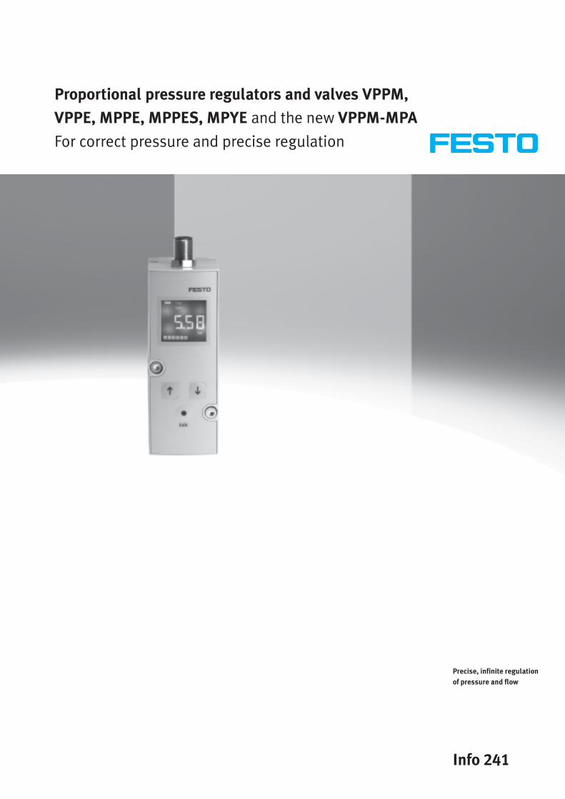
Proportional pressure regulators and valves VPPM,
VPPE, MPPE, MPPES, MPYE and the new VPPM-MPA
For correct pressure and precise regulation
Info 241
Precise, infinite regulation
of pressure and flow

Info 241 – Subject to change – 2008/072 Internet: www.festo.com/catalogue/...
Reliable pressure and flow control
Applying pressure correctly – plus easy installation and precise regulation
Fast dynamic response, high repetition accuracy, short switching times, linear
characteristics and stable regulation – these features can significantly improve
product quality by precise adjustment and control of the process variables. These
proportional pressure regulators provide infinite adjustment of pressure and
thereby the force or flow, enabling the user to preset pressures, piston speeds
and rotational speeds electrically.
Regulation at the press of a button … sturdy – with 3 presets … variable – via fieldbus
VPPM – the new dimension …
… in proportional pressure regulators.
The right parameters for each applica-
tion – simply choose the correct regu-
lator characteristic from 3 presets at
the press of a button. Specialists are
no longer required. Reliable regula-
tion due to two-stage control circuit
with multi-sensor control.
Pure individuality
Our modules for the VPPM are pre-
cisely adjusted to your requirements –
for electronic, pneumatic and
mechanical systems with maximum
versatility.
Versatility
Inline or flanged version, current con-
trolled, voltage controlled, connection
to fieldbus/Ethernet via CPX terminal.
From basic performance to high-tech
product – something completely new.
Multi-sensor control
Integrated sensors for optimum
regulation results and behaviour.
Temperature-compensated, which
means no pressure drifting during
temperature changes.
Diagnostics
The VPPM reports the pressure
reached as an electrical signal. It can
also diagnose a specified value that
cannot be reached. Almost all values
can be remotely controlled and moni-
tored via CPX.

LED or LCD versions of proportional
pressure regulators
1 Connector plug
M12, 8-pin
2 Status LEDs
Power/Error
3 3 preset LEDs
fast/universal/precise
4 3 pushbuttons for simple
operation (choice of presets)
5 Display of current pressure
6 Presets can be selected via
buttons or digital inputs
7 Adjustable pressure range
8 Different switch modes for switch
output (diagnostics function)
9 Choice of units (bar, kPa or psi)
aJ Bar display for identifying
dynamic processes
2008/07 – Subject to change – Info 241 3 Internet: www.festo.com/catalogue/...
Main application
Can be put to universal use. Whether
Advantages for commissioning and
maintenance
Only from Festo – reliable regulation
with multi-sensor controlp
it is accuracy or speed that is required
at the press of a button, or processes
where force and pressure must be
regulated precisely and flexibly,
reliable regulation behaviour
guarantees optimum results.
• Festo plug & work®: no adjustment
of the control circuit required
• No need to store special
attachments
• Immediate commissioning
• Shorter retooling times
• Remote control regulation
behaviour (presets – rapid,
universal and precise)
• Can be adjusted to the application
individually via presets
• Choice of several pressure ranges
• Process-optimised cylinder speed
• Flexible, adjustable flow rates
• Special adaptation possible
fast
universal
precise
• Special adaptation possible
Without multi-sensor control
generally causes overshooting.

Handheld device
I/O modules
digital/analogue
End plate
Fieldbus node
Technology module
Front End Control
Compact vision system
SBOx
Info 241 – Subject to change – 2008/074 Internet: www.festo.com/catalogue/...
VPPM-MPA on CPX/MPA –
proportional technology in threefold linking
Versatile – integration into
automation systems
The MPA valve terminal with fieldbus
connection communicates in many
different languages and is able to
communicate with the fieldbus
systems and automation systems of
leading manufacturers.
Faster configuration using CPX macro
Systematically more reliable and
quicker planning and configuration
with CPX modules – the CPX macro
library for the electrical CAE software
Eplan.
High flexibility due to individual
pressure zones
New technologies and innovative
products enable many possibilities.
The pressure control valve integrated
in a valve terminal offers remote con-
trolled pressure zone regulation and
therefore more flexibility in many pro-y y p
cesses. For example, a proportional
control valve enables several static
pressures to be set with low air
consumption and by multiplexing.
Simple – service and commissioning
The small, convenient handheld CPX-
MMI facilitates data requisitions,
configuration and diagnostic
functions for CPX/MPA on-site – in
plain text, without programming.

Pneumatic interface
Manifold
block
Identification plate
Push-in fitting
Separating
seal
MPA1: Manifold block
fitted with 4 valves
Integrated VPPM proportional
pressure regulator
Supply plate with flat plate
silencer
MPA2: manifold block
fitted with 2 valves
Integrated
pressure sensor
End plate
Electric
module
Manual pressure regulator
with manometer
Sub-base valve
Manual override
Better performance
thanks to technology modules
CPX-FEC provides a programmable
valve terminal – remote controller on
the fieldbus or Ethernet as a pre-
processing unit for decentralised,
autonomous subsystems. The CPX-CPI
interface permits centralised and
decentralised pneumatic/electrical
systems side-by-side – leading to
shorter cycle times and lower wiring
costs.
Easy integration of the latest SBOx
vision system in IP65 on CPX/MPA –
simpler I/O operation, on CPI interface
or via Ethernet.
For flexible and innovative quality
assurance.
4xM12
metal
8xM12
metal
M12
5-pin
M8
3-pin
Sub-D
Harax® M12
8-pin
Cage
Clamp®M8
4-pin
M12
5-pin
metal
thread
Innovation thanks to function
integration
The serial linking within the MPA
makes this possible:
VPPM-MPA pressure control valve
• Pressure ranges 0.02 … 2 bar/
0.06 … 6 bar/0.1 … 10 bar
• flow up to 1400 l/min
• 3 presets can be accessed
• programmable switching points
• pressure range can be set
• temperature compensation
• highly accurate cascade regulation
thanks to multi-sensor technology
Extremely adaptable connection
technology
2008/07 – Subject to change – Info 241 5 Internet: www.festo.com/catalogue/...

Info 241 – Subject to change – 2008/076 Internet: www.festo.com/catalogue/...
Proportional pressure regulators VPPMGeneral information
VPPM
Assembly
repositionable by 180°
In-line valve H-rail mounting
LED indicators Display
Sub-base valve
Manifold block
Compressed air supply at both endsWorking lines
Venting at both endsPlug socket with cableControl elements
Innovative Versatile Reliable Easy to mount
• Multi-sensor control
(cascade control)
• Diagnostics
• Choice of regulation characteristics
• Temperature compensated
• High dynamic response
• High repetition accuracy
• Modular product system
• Individual valves (in-line valve)
• Manifold valves (sub-base/flange
valve)
• Various user interfaces
– LED indicators
– LCD display
– Adjustment/selection buttons
• A choice of valves with different
pressure ranges
• Pressure range can be modified on
the valve
• Choice of different setpoint
specifications
– Current input
– Voltage input
• Integrated pressure sensor
– with independent output
• Open circuit monitoring
• Pressure is maintained if the
controller fails
• Manifold block
• H-rail mounting
• Individually via mounting bracket
• QS fittings
-V- New

2008/07 – Subject to change – Info 241 7 Internet: www.festo.com/catalogue/...
Proportional pressure regulators VPPMGeneral information
VPPM on the valve terminal MPA
24V
Serial data
Innovative Versatile Reliable Easy to mount
• Multi-sensor control
• Diagnostics via bus
• Choice of regulation characteristics
• High dynamic response
• 2 accuracy levels
• Pressure zone regulation
• Multiplexing
• For all common protocols
• As an individual pressure regulator
• As a pressure zone regulator
• Choice of 3 valves with different
pressure ranges
• 3 pressure ranges (presets) can be
set via the bus
• Internal or external compressed air
supply possible
• Long service life
• LED display for the operating status
• Pressure is maintained if the supply
voltage fails
• Fast troubleshooting thanks to LEDs
on the valves and diagnostics via
fieldbus
• Ease of servicing through
replaceable valves
• Simple replacement of the valves
• Tested units
• Easy extension of the valve terminal
-V- New

Info 241 – Subject to change – 2008/078 Internet: www.festo.com/catalogue/...
Proportional pressure regulators VPPMGeneral information
Layout of a control circuit
Closed-loop
control element
Final control
element
Controlled
system
Measuring
device
Closed-loop controller (integrated electronics)
Comparator
(Valve piston)
(Valve output and all
downstream components)
Disturbance z
(e.g. leakage)
Controlled variable
x (pressure)Reference
variable w
(setpoint
value)
Feedback signal r
System deviation e
Layout Method of operation
The figure shows a closed-loop control
circuit. The reference variable w
(setpoint value, e.g. 5 volts or 8 mA)
initially acts on a comparator. The
measuring device sends the controlled
variable x value (actual value,
e.g. 3 bar) to the comparator as a
feedback signal r. The closed-loop
control element detects the system
deviation e and actuates the final
control element. The output of the
final control element acts on the con-
trolled system. The closed-loop control
element thus attempts to compensate
for the difference between the refer-
ence variable w and the controlled
variable x by using the final control
element.
This process runs continuously so
changes in the reference variable are
always detected. However, a system
deviation will also appear if the
reference variable is constant but the
controlled variable changes. This
happens when the flow through the
valve changes in response to a
switching action, a cylinder movement
or a change in load. The disturbance
variable z will also cause a system
deviation. An example of this is when
the pressure drops in the air supply.
The disturbance variable z acts on the
controlled variable x unintentionally.
In all cases, the regulator attempts to
readjust the controlled variable x to
the reference variable w.
Multi-sensor control (cascade control) of the VPPM
Diaphragm
pressure
regulator
Pilot control
stageMain stage
Working
pressure
regulator
Working
volume
Pilot solenoid
coilsSetpoint
value
Actual
value
Sensor 1
Sensor 2
Cascade control Control precision
Unlike conventional direct-acting
regulators, with multi-sensor control
several control circuits are nested in-
side each other. The overall controlled
system is divided into smaller sub-
controlled circuits that are easier to
control for the specific task.
Multi-sensor control significantly im-
proves control precision and dynamic
response in comparison with single-
acting regulators.
-V- New

2008/07 – Subject to change – Info 241 9 Internet: www.festo.com/catalogue/...
Proportional pressure regulators VPPMGeneral information
Terms related to the proportional pressure regulator
Hysteresis Linearity error
There is always a linear relationship
within a certain tolerance between the
setpoint value entered and the pres-
sure output. Nevertheless it makes a
difference whether the setpoint value
is entered as rising or falling. The
difference between the maximum
deviations is referred to as hysteresis.
A perfectly linear progression of the
control characteristic of the output
pressure is theoretical. The maximum
percentage deviation from this theor-
etical control characteristic is referred
to as the linearity error. The percen-
tage value refers to the maximum
output pressure (full scale).
Response sensitivity Repetition accuracy (reproducibility)
3.61 bar
3.60 bar
The response sensitivity of the device
determines how sensitively one can
change, i.e. adjust, a pressure.
The smallest setpoint value difference
that results in a change in the output
pressure is referred to as the response
sensitivity. In this case, 0.01 bar.
The repetition accuracy is the margin
within which the fluid output vari-
ables are scattered when the same
electrical input signal coming from
the same direction is repeatedly
adjusted. The repetition accuracy is
expressed as a percentage of the
maximum fluid output signal.
Zero offset Pressure range adaptation
1 3 4 5 6 7 8 9 1 020
1
2
3
4
5
6
7
8
9
1 0
If, for example, a VPPM cannot be
vented for safety reasons, the mini-
mum pressure can be increased from
the zero point. The smallest setpoint
value is then assigned an output
pressure of 5 bar, for example, and
the largest setpoint value an output
pressure of 10 bar. Zero suppression
is automatically switched off if zero
offsetting is used.
In the delivery condition, 100% set-
point value equals 100% fluid output
signal. Pressure range adaptation or
adjustment enables the fluid output
variable to be matched to the setpoint
value.
Zero point suppression
0.1 V3.6-4.12 mA
x mbar
In practice there exists the possibility
of residual voltage or residual current
at the setpoint input of the VPPM via
the setpoint generator.
Zero point suppression is used so that
the valve is reliably vented at a
setpoint value of zero.
-V- New
Info 241 – Subject to change – 2008/0710 Internet: www.festo.com/catalogue/...
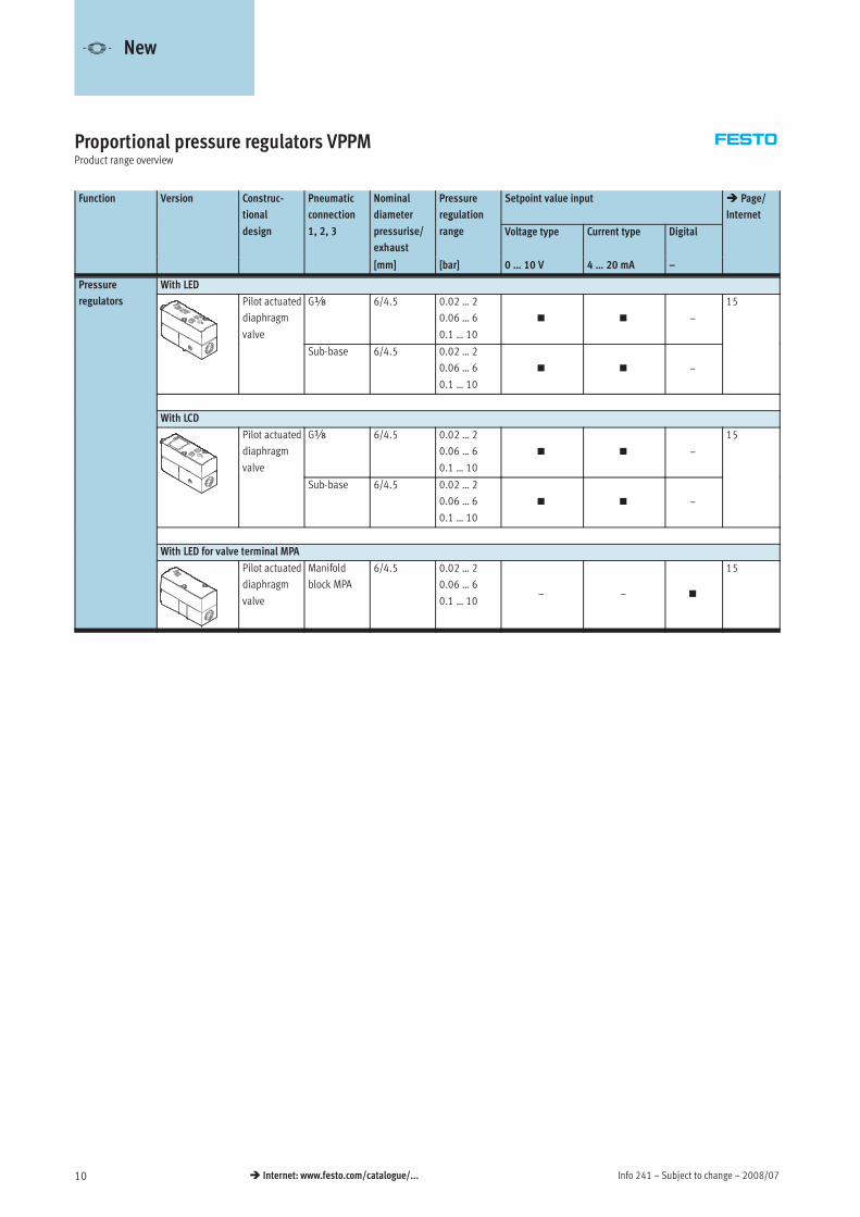
Proportional pressure regulators VPPMProduct range overview
Function Version Construc-
tional
Pneumatic
connection
Nominal
diameter
Pressure
regulation
Setpoint value input Page/
Internet
design 1, 2, 3 pressurise/
exhaust
g
range Voltage type Current type Digital
[mm] [bar] 0 … 10 V 4 … 20 mA –
Pressure With LED
regulators Pilot actuated
diaphragm
valve
Gx 6/4.5 0.02 … 2
0.06 … 6
0.1 … 10
–
15
Sub-base 6/4.5 0.02 … 2
0.06 … 6
0.1 … 10
–
With LCD
Pilot actuated
diaphragm
valve
Gx 6/4.5 0.02 … 2
0.06 … 6
0.1 … 10
–
15
Sub-base 6/4.5 0.02 … 2
0.06 … 6
0.1 … 10
–
With LED for valve terminal MPA
Pilot actuated
diaphragm
valve
Manifold
block MPA
6/4.5 0.02 … 2
0.06 … 6
0.1 … 10– –
15
-V- New
2008/07 – Subject to change – Info 241 11 Internet: www.festo.com/catalogue/...
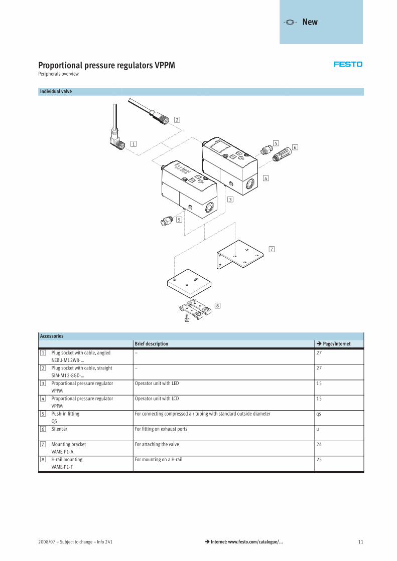
Proportional pressure regulators VPPMPeripherals overview
Individual valve
1
2
3
4
56
7
5
8
Accessories
Brief description Page/Internet
1 Plug socket with cable, angled
NEBU-M12W8-…
– 27
2 Plug socket with cable, straight
SIM-M12-8GD-…
– 27
3 Proportional pressure regulator
VPPM
Operator unit with LED 15
4 Proportional pressure regulator
VPPM
Operator unit with LCD 15
5 Push-in fitting
QS
For connecting compressed air tubing with standard outside diameter qs
6 Silencer For fitting on exhaust ports u
7 Mounting bracket
VAME-P1-A
For attaching the valve 24
8 H-rail mounting
VAME-P1-T
For mounting on a H-rail 25
-V- New

Info 241 – Subject to change – 2008/0712 Internet: www.festo.com/catalogue/...
Proportional pressure regulators VPPMPeripherals overview
Valve manifold
1
2
4
5
6
7
3
5
6
6
3
5
5
9
8
8
Accessories
Brief description Page/Internet
1 Plug socket with cable, angled
NEBU-M12W8-…
– 27
2 Plug socket with cable, straight
SIM-M12-8GD-…
– 27
3 Proportional pressure regulator
VPPM
Operator unit with LED 15
4 Proportional pressure regulator
VPPM
Operator unit with LCD 15
5 Blanking plug
B
– b
6 Push-in fitting
QS
For connecting compressed air tubing with standard outside diameter qs
7 Manifold block
VABM
– 22
8 Silencer For fitting on exhaust ports u
9 Blanking plate
VABB-P1
For vacant position; seal and countersunk screws included in the scope of delivery 23
-V- New

2008/07 – Subject to change – Info 241 13 Internet: www.festo.com/catalogue/...
Proportional pressure regulators VPPMSystem overview
VPPM for valve terminal MPA
1
2
4
5
36
Accessories
Brief description Page/Internet
1 Valve terminal MPA With fieldbus connection and VPPM mpa
2 Proportional pressure regulator VPPM For valve terminal MPA mpa
3 Electrical manifold module
VMPA1-FB-EV-AB
For sub-base of the proportional pressure regulator mpa
4 Sub-base VMPA-FB-AP-P1 Without electrical manifold module and electrical module mpa
5 Push-in fitting QS – qs
6 Attachment VMPA-BG – mpa
-V- New

Info 241 – Subject to change – 2008/0714 Internet: www.festo.com/catalogue/...
Proportional pressure regulators VPPMType codes
VPPM — 6 L — L — 1 — G18 — 0L 6H — V1 N — S1 —
Type
VPPM Modular proportional pressure regulator
Nominal diameter
6 6 mm
Design
L In-line valve
F Flanged valve
Mounting method
Freely mountable
Dynamic response class
L Low
Valve function
1 3/2-way valve, normally closed
Pneumatic connection
G18 Thread Gx
F Flange/sub-base
Lower pressure value of regulation range
0L 0 bar
Upper pressure value of regulation range
2H 2 bar
6H 6 bar
10H 10 bar
Setpoint specification for individual valve
V1 0 … 10 V
A4 4 … 20 mA
Switching output
N Negative switching
P Positive switching
Accuracy
2% (standard)
S1 1%
Operator unit
LED (standard)
C1 With LCD, pressure unit variable
-V- New

2008/07 – Subject to change – Info 241 15 Internet: www.festo.com/catalogue/...
Proportional pressure regulators VPPMTechnical data
-M- Flow rate
380 … 1,400 l/min
-P- Voltage
21.6 … 26.4 V DC
-L- Pressure regulation range
0.02 … 10 bar
Variants
• Setpoint input as analogue voltage
signal 0 … 10 V
• Setpoint input as analogue current
signal 4 … 20 mA
• LED version
• With LCD display
• NPN or PNP switching output
• Integration in valve terminal via
fieldbus
General technical data
Gx Sub-base Valve terminal MPA
Constructional design Pilot actuated diaphragm regulator
Sealing principle Soft
Actuation type Electric
Type of control Pilot actuated via 2/2-way valves
Type of mounting Via through-hole, via accessories
Mounting position Any
Nominal diameter Pressurisation [mm] 6
Exhaust [mm] 4.5
Standard nominal flow rate [l/min] Graphs
Product weight [g] 400
Electrical data
Gx Sub-base Valve terminal MPA
Electrical connection Plug, round design, 8-pin, M12 Terminal linking
Operating voltage range [V DC] 24 ± 10% = 21.6 … 26.4
Residual ripple 10%
Max. electrical power consumption [W] 7
Signal setpoint input Voltage [V DC] 0 … 10 Digitally via fieldbusg p p
Current [mA] 4 … 20
g y
Protection against short circuit For all electrical connections
Protection against polarity reversal For all electrical connections
Protection class IP65
CE mark EU conformity in accordance with the directive 89/336/EEC (EMC)
-V- New
-H- Note
If the power supply cable is
interrupted, output pressure is
maintained unregulated.

Info 241 – Subject to change – 2008/0716 Internet: www.festo.com/catalogue/...
Proportional pressure regulators VPPMTechnical data
Flow rate qn from 1 as a function of output pressure p2
VPPM-6L-…-0L2H-… (2 bar) VPPM-6L-…-0L6H-… (6 bar)
VPPM-6L-…-0L10H-… (10 bar)
Flow rate qn from 2 3 as a function of output pressure p2
VPPM-6L-…-0L2H-… (2 bar) VPPM-6L-…-0L6H-… (6 bar)
VPPM-6L-…-0L10H-… (10 bar)
-V- New
2008/07 – Subject to change – Info 241 17 Internet: www.festo.com/catalogue/...
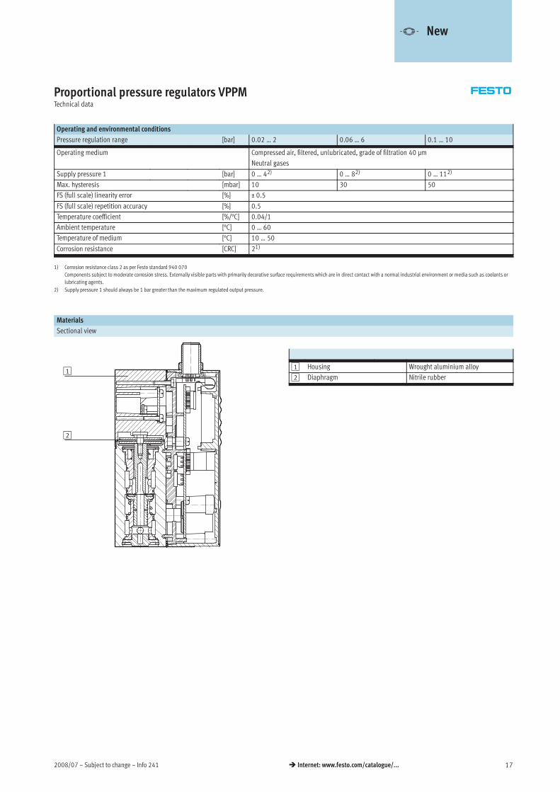
Proportional pressure regulators VPPMTechnical data
Operating and environmental conditions
Pressure regulation range [bar] 0.02 … 2 0.06 … 6 0.1 … 10
Operating medium Compressed air, filtered, unlubricated, grade of filtration 40 μm
Neutral gases
Supply pressure 1 [bar] 0 … 42) 0 … 82) 0 … 112)
Max. hysteresis [mbar] 10 30 50
FS (full scale) linearity error [%] ± 0.5
FS (full scale) repetition accuracy [%] 0.5
Temperature coefficient [%/°C] 0.04/1
Ambient temperature [°C] 0 … 60
Temperature of medium [°C] 10 … 50
Corrosion resistance [CRC] 21)
*
1) Corrosion resistance class 2 as per Festo standard 940 070
Components subject to moderate corrosion stress. Externally visible parts with primarily decorative surface requirements which are in direct contact with a normal industrial environment or media such as coolants or
lubricating agents.
2) Supply pressure 1 should always be 1 bar greater than the maximum regulated output pressure.
Materials
Sectional view
1 Housing Wrought aluminium alloy
2 Diaphragm Nitrile rubber
-V- New
1
2

Info 241 – Subject to change – 2008/0718 Internet: www.festo.com/catalogue/...
Proportional pressure regulators VPPMTechnical data
Dimensions Download CAD data www.festo.com
VPPM-6F With LCD
1 Socket head screw M5x65
VPPM-6L With LCD
D1 = Gx
M12 – Pin allocation
1 Digital input D1
2 DC +24 V supply voltage
3 Analogue input W–
4 Analogue input W+
5 Digital input D2
6 Analogue output X
7 DC 0 V or GND
8 Digital output D3
-V- New

2008/07 – Subject to change – Info 241 19 Internet: www.festo.com/catalogue/...
Proportional pressure regulators VPPMTechnical data
Ordering data
Pneumatic connection Pressure
regulation range
Voltage type 0 … 10 V Current type 4 … 20 mA
[bar] Part No. Type Part No. Type
Overall accuracy 2%
Gx 0.02 … 2 542 233 VPPM-6L-L-1-G18-0L2H-V1N 542 236 VPPM-6L-L-1-G18-0L2H-A4Nx
0.06 … 6 542 234 VPPM-6L-L-1-G18-0L6H-V1N 542 237 VPPM-6L-L-1-G18-0L6H-A4N
554 043 VPPM-6L-L-1-G18-0L6H-V1P 554 045 VPPM-6L-L-1-G18-0L6H-A4P
558 337 VPPM-6L-L-1-G18-0L6H-V1P-C1 558 338 VPPM-6L-L-1-G18-0L6H-A4P-C1
0.1 … 10 542 235 VPPM-6L-L-1-G18-0L10H-V1N 542 238 VPPM-6L-L-1-G18-0L10H-A4N
554 044 VPPM-6L-L-1-G18-0L10H-V1P 554 046 VPPM-6L-L-1-G18-0L10H-A4P
Sub-base 0.02 … 2 542 245 VPPM-6F-L-1-F-0L2H-V1N 542 248 VPPM-6F-L-1-F-0L2H-A4N
0.06 … 6 542 246 VPPM-6F-L-1-F-0L6H-V1N 542 249 VPPM-6F-L-1-F-0L6H-A4N
558 339 VPPM-6F-L-1-F-0L6H-V1P-C1 558 340 VPPM-6F-L-1-F-0L6H-A4P-C1
558 347 VPPM-6F-L-1-F-0L6H-V1N-C1
0.1 … 10 542 247 VPPM-6F-L-1-F-0L10H-V1N 542 250 VPPM-6F-L-1-F-0L10H-A4N
Overall accuracy 1%
Gx 0.02 … 2 542 227 VPPM-6L-L-1-G18-0L2H-V1N-S1 542 230 VPPM-6L-L-1-G18-0L2H-A4N-S1x
0.06 … 6 542 228 VPPM-6L-L-1-G18-0L6H-V1N-S1 542 231 VPPM-6L-L-1-G18-0L6H-A4N-S1
554 039 VPPM-6L-L-1-G18-0L6H-V1P-S1 554 041 VPPM-6L-L-1-G18-0L6H-A4P-S1
0.1 … 10 542 229 VPPM-6L-L-1-G18-0L10H-V1N-S1 542 232 VPPM-6L-L-1-G18-0L10H-A4N-S1
554 040 VPPM-6L-L-1-G18-0L10H-V1P-S1 554 042 VPPM-6L-L-1-G18-0L10H-A4P-S1
558 335 VPPM-6L-L-1-G18-0L10H-V1P-S1-C1 558 336 VPPM-6L-L-1-G18-0L10H-A4P-S1-C1
Sub-base 0.02 … 2 542 239 VPPM-6F-L-1-F-0L2H-V1N-S1 542 242 VPPM-6F-L-1-F-0L2H-A4N-S1
0.06 … 6 542 240 VPPM-6F-L-1-F-0L6H-V1N-S1 542 243 VPPM-6F-L-1-F-0L6H-A4N-S1
0.1 … 10 542 241 VPPM-6F-L-1-F-0L10H-V1N-S1 542 244 VPPM-6F-L-1-F-0L10H-A4N-S1
-H- Note
Further variants can be ordered using
the modular system.
20
VPPM for MPA fieldbus variant in-
cluding accessories must be ordered
together with the valve terminal.
internet: mpa
Dimensions Download CAD data www.festo.com
VPPM for valve terminal MPA
1 Socket head screw M4x55
-V- New

Info 241 – Subject to change – 2008/0720 Internet: www.festo.com/catalogue/...
Proportional pressure regulators VPPMOrdering data – Modular products
Mandatory data0M
Module No. Design Nominal diameter Valve type Dynamic response Valve mode Type of connection
543 432 VPPM 6 L
F
L 1 G18
F
Order
example
543 432 VPPM – 6 F – L – 1 – F
Ordering table
Size 6 Condi-
tions
Code Enter
code
0M Module No. 543 432
Design Modular pressure regulator VPPM VPPM
Nominal diameter 6 -6 -6
Valve type In-line 1 Lyp
Flanged valve 2 F
Dynamic response Low dynamic response (pilot-actuated, soft-sealing) -L -L
Valve mode 3/2-way valve, normally closed -1 -1
Type of connection Gx thread -G18
yp
Flange/sub-base -F
1 L Only with connection type G18 (Gx thread) 2 F Only with connection type F (flange/sub-base)
Transfer order code
543 432 VPPM – 6 – L – 1 –
-V- New

2008/07 – Subject to change – Info 241 21 Internet: www.festo.com/catalogue/...
Proportional pressure regulators VPPMOrdering data – Modular products
Mandatory data0M Options0O
Pressure
regulation range
Alternative lower
pressure
regulation range
Alternative upper
pressure
regulation range
Setpoint
specification
Switching output Overall accuracy Operator unit
0L2H
0L6H
0L10H
0.1 … 10L 0.1 … 10H V1
A4
P
N
S1 C1
– 6.5L 7.1H – A4 P – S1 C1
Ordering table
Size 6 Condi-
tions
Code Enter
code
Pressure regulation range 0 … 2 bar -0L2H
0M
g g
0 … 6 bar -0L6H
0 … 10 bar -0L10H
Alternative lower pressure
regulation range
0.1 … 10 bar 3 -…L
Alternative upper pressure
regulation range
0.1 … 10 bar 4 …H
Setpoint specification Voltage (standard 0 … 10 V) -V1p p
Current (standard 4 … 20 mA) -A4
Switching output Positive switching Pg p
Negative switching N
0O Overall accuracy 1% -S1
Operator unit With LCD, pressure unit variable C1
3 …L Not with pressure regulation range (0L2H, 0L6H, 0L10H).
Must always be less than alternative upper pressure regulation range H
4 …H Not with pressure regulation range (0L2H, 0L6H, 0L10H).
Must always be greater than alternative lower pressure regulation range L
Transfer order code
– – –
-V- New

Info 241 – Subject to change – 2008/0722 Internet: www.festo.com/catalogue/...
Proportional pressure regulators VPPMAccessories
Sub-base VABM-P1
Material:
Wrought aluminium alloy
Dimensions Download CAD data www.festo.com
1 Proportional pressure regulator
VPPM
Dimensions and ordering data
Valve positions L1 L2 L3 Weight CRC1) Part No. Typep 3
[g]
yp
2 113 96 42 900 2 542 252 VABM-P1-SF-G18-2-P3
3 155 138 84 1,230 2 542 253 VABM-P1-SF-G18-3-P3
4 197 180 126 1,565 2 542 254 VABM-P1-SF-G18-4-P3
1) Corrosion resistance class 2 as per Festo standard 940 070
Components subject to moderate corrosion stress. Externally visible parts with primarily decorative surface requirements which are in direct contact with a normal industrial environment or media such as coolants or
lubricating agents.
-V- New

2008/07 – Subject to change – Info 241 23 Internet: www.festo.com/catalogue/...
Proportional pressure regulators VPPMAccessories
Blanking plate VABB-P1
Material:
Wrought aluminium alloy, NBR, steel
Dimensions Download CAD data www.festo.com
1 Countersunk screw M4x10 2 Seal VMPA- …
Ordering data
Weight CRC Part No. Type
[g]
yp
35 11) 558 350 VABB-P1
1) Corrosion resistance class 1 as per Festo standard 940 070
Components requiring low corrosion resistance. Transport and storage protection. Parts that do not have primarily decorative surface requirements, e.g. in internal areas that are not visible or behind covers.
-V- New

Info 241 – Subject to change – 2008/0724 Internet: www.festo.com/catalogue/...
Proportional pressure regulators VPPMAccessories
Mounting bracket VAME-P1-A
Material:
Wrought aluminium alloy, steel
Dimensions Download CAD data www.festo.com
1 Socket head screw M4 2 Proportional pressure regulator
VPPM
3 Mounting bracket can be
reversed if required
Ordering data
Weight CRC Part No. Type
[g]
yp
71 11) 542 251 VAME-P1-A
1) Corrosion resistance class 1 as per Festo standard 940 070
Components requiring low corrosion resistance. Transport and storage protection. Parts that do not have primarily decorative surface requirements, e.g. in internal areas that are not visible or behind covers.
-V- New
2008/07 – Subject to change – Info 241 25 Internet: www.festo.com/catalogue/...
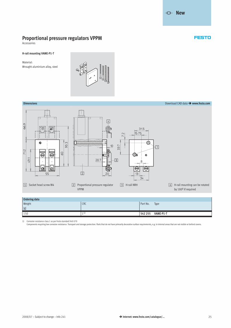
Proportional pressure regulators VPPMAccessories
H-rail mounting VAME-P1-T
Material:
Wrought aluminium alloy, steel
Dimensions Download CAD data www.festo.com
1 Socket head screw M4 2 Proportional pressure regulator
VPPM
3 H-rail NRH 4 H-rail mounting can be rotated
by 180º if required
Ordering data
Weight CRC Part No. Type
[g]
yp
150 11) 542 255 VAME-P1-T
1) Corrosion resistance class 1 as per Festo standard 940 070
Components requiring low corrosion resistance. Transport and storage protection. Parts that do not have primarily decorative surface requirements, e.g. in internal areas that are not visible or behind covers.
-V- New

Info 241 – Subject to change – 2008/0726 Internet: www.festo.com/catalogue/...
Proportional pressure regulators VPPMAccessories
Plug socket with cable
NEBV-M12G8-KD-3-M12G4
For connecting the VPPM with the
analogue input and output modules
of the controller CPX.
Dimensions and pin allocation Download CAD data www.festo.com
A (AI module) B (AO module)
C
1 Straight socket, 8-pin, to VPPM 2 Straight plug, 4-pin, to CPX
modules
-V- New

2008/07 – Subject to change – Info 241 27 Internet: www.festo.com/catalogue/...
Proportional pressure regulators VPPMAccessories
Plug socket with cable
NEBV-M12G8-K-2-M12G4
NEBV-M12G8-K-5-M12G4
For connecting the VPPM with the ana-
logue output modules of the controller
CPX.
Dimensions and pin allocation Download CAD data www.festo.com
A (AO module)
B
Type 2 1 L1
NEBV-M12G8-K-2-M12G4 Straight socket, M12, Straight plug, M12, 2 m
NEBV-M12G8-K-5-M12G4
g , ,
8-pin to VPPM
g p g, ,
4-pin to CPX module 5 m
Ordering data
Description Cable length Part No. Typep
[m]
yp
Plug socket with cable Technical data Internet: plug socket with cable
Straight socket, 8-pin, M12 2 525 616 SIM-M12-8GD-2-PU
5 525 618 SIM-M12-8GD-5-PU
Angled socket, 8-pin, M12 2 542 256 NEBU-M12W8-2-N-LE8
5 542 257 NEBU-M12W8-5-N-LE8
One straight socket, 8-pin, and one straight plug, 4-pin 2 553 575 NEBV-M12G8-K-2-M12G4
5 553 576 NEBV-M12G8-K-5-M12G4
One straight socket, 8-pin, and two straight plugs, 4-pin – 547 888 NEBV-M12G8-KD-3-M12G4
-V- New

Info 241 – Subject to change – 2008/0728 Internet: www.festo.com/catalogue/...
Proportional pressure regulators MPPE/VPPE/MPPESProduct range overview
Function Version Type Constructional
design
Pneumatic
connection 1
Nominal size
pressurising/
exhaust
Pressure
regulation
range1)
Setpoint value input Page/Internet
Voltage type Current type
[mm] [bar] 0 … 10 V 4 … 20 mA
Pressure with pilot control via 2/2-way valves (switching valves)
regulators MPPE Pilot-actuated
poppet valve
Gx 5/5 0 … 1
0 2 5 34
poppet valveG¼ 7/7
0 … 2.5
0 … 6
G½ 11/12 0 … 10
VPPE Pilot-actuated
t l
Gx 5/2.5 0.15 … 6 30
poppet valve –
with proportional solenoid
MPPES Directly-
actuated valve
Gx 3/2 0 … 2
0 … 6
40
Pilot-actuated G¼ 7/7 0 … 10
valve G½ 11/12
1) Pressure regulation range also by customer request

2008/07 – Subject to change – Info 241 29 Internet: www.festo.com/catalogue/...
Proportional pressure regulators MPPE/VPPE/MPPESPeripherals overview
1
3
4
6
8
2 7
1
5
1
1
9
aA
aJ
5
Accessories
Brief description Page/Internet
1 Push-in fitting QS For connecting compressed air tubing with standard O.D. quick star
2 Silencer For fitting in exhaust ports u
3 Setpoint value module MPZ For generating 6+1 analogue voltage signals 54
4 Angled plug socket MPPE-3-B – 46
5 Plug socket with cable KMPE-B – 46
6 Connecting cable KVIA-MPPE – 46
7 Proportional pressure regulator
MPPE
– 35
8 Digital input/output For controlling the setpoint module –
9 Proportional pressure regulator
VPPE
– 31
aJ Plug socket, angled
SIE-WD-TR
– sie-wd
– Plug socket, straight SIE-GD – sie-gd
aA Plug socket with cable, angled
SIM-M12-4WD-5PU
– 46
– Plug socket with cable, straight
SIM-M12-4GD-5PU
– 46

Info 241 – Subject to change – 2008/0730 Internet: www.festo.com/catalogue/...
Proportional pressure regulators VPPEType codes
VPPE — 3 — x — 6 — 010
Type
VPPE Proportional pressure regulator with
switching valve head
Valve function
3 3-way pressure regulator
Pneumatic connection
x Female thread Gx
Pressure regulation range
6 0.15 … 6 bar
Analogue setpoint value input
010 0 … 10 V

2008/07 – Subject to change – Info 241 31 Internet: www.festo.com/catalogue/...
Proportional pressure regulators VPPETechnical data
-M- Flow rate
600 l/min
-P- Voltage
21.6 … 26.4 V DC
-L- Pressure regulation range
0.15 … 6 bar
Variants
• Setpoint value input as analogue
voltage signal 0 … 10 V
VPPE-3-…
General technical data
Pneumatic connection 1 and 2 Gx
Constructional design Pilot-actuated piston regulator
Sealing principle Soft
Actuation mode Electrical
Pilot control mode Pilot actuated via 2/2-way valves
Type of mounting Via through-holes
Assembly position Any
Nominal size Ventilation [mm] 5
Exhaust [mm] 2.5
Standard nominal flow rate [l/min] Graphs
Product weight [g] 420
Flow rate qn as a function of the output pressure p2
qn [l/min]
p2[bar]
Electrical data
Electrical connection Plug, round design, 4-pin, M12x1
Operating voltage range [V DC] 21.6 … 26.4
Residual ripple 10 %
Max. electrical power consumption [W] 2.5
Signal setpoint value input [V DC] 0 … 10
Protection against short circuit For all electrical connections
Protection against polarity reversal For all electrical connections
Protection class IP65
CE symbol EU conformity in accordance with the directive 89/336/EEC (EMC)

Info 241 – Subject to change – 2008/0732 Internet: www.festo.com/catalogue/...
Proportional pressure regulators VPPETechnical data
Operating and environmental conditions
Operating medium Filtered compressed air, grade of filtration 40μm
Neutral gases
Input pressure 1 [bar] 7 … 8
Pressure regulation range [bar] 0.15 … 6
Max. hysteresis [bar] 0.15
Ambient temperature [°C] 10 … 50
Temperature of medium [°C] 10 … 50
Corrosion resistance class CRC1) 2*
1) Corrosion resistance class 2 according to Festo standard 940 070
Components requiring moderate corrosion resistance. Externally visible parts with primarily decorative surface requirements which are in direct contact with a normal industrial environment or media such as coolants
or lubricating agents.
Materials
Sectional view
1 Housing Wrought aluminium alloy
2 Diaphragm Nitrile rubber
-H- Safety advice
If the power supply cable is
interrupted, output pressure is
maintained unregulated.
1
2

2008/07 – Subject to change – Info 241 33 Internet: www.festo.com/catalogue/...
Proportional pressure regulators VPPETechnical data
Dimensions Download CAD data www.festo.com
1 Earth connection
M12x1 – Terminal allocation
1 Power supply
21.6 … 26.4 V DC
2 Nominal value (–)
3 GND (–)
4 Nominal value (+) 0 … 10 V DC
Ordering data
Pneumatic connection Pressure regulation range
[bar] Part No. Type
Gx 0 6 539 639 VPPE 3 x 6 010Gx 0 … 6 539 639 VPPE-3-x-6-010Gx 0 … 6 539 639 VPPE-3-x-6-010

Info 241 – Subject to change – 2008/0734 Internet: www.festo.com/catalogue/...
Proportional pressure regulators MPPEType codes
Basic version
MPPE — 3 — x — 1 — 010 — B
Type
MPPE Proportional pressure regulator with
switching valve
Valve function
3 3-way pressure regulator
Pneumatic connection
x Gx
¼ G¼
½ G½
Pressure regulation range
1 0 … 1 bar
2.5 0 … 2.5 bar
6 0 … 6 bar
10 0 … 10 bar
Setpoint value input
010 Analogue voltage signal
420 Analogue current signal
Generation
B B series
Special pressure regulation range by customer request
MPPE — 3 — x — 1 — 6 — 010 — B
Type
MPPE Proportional pressure regulator with
switching valve
Valve function
3 3-way pressure regulator
Pneumatic connection
x Gx
¼ G¼
½ G½
Required pressure at 0 V or 4 mA [bar]
Required pressure at 10 V or 20 mA [bar]
Setpoint value input
010 Analogue voltage signal
420 Analogue current signal
Generation
B B series

2008/07 – Subject to change – Info 241 35 Internet: www.festo.com/catalogue/...
Proportional pressure regulators MPPETechnical data
-M- Flow rate
350 … 5,500 l/min
-P- Voltage
18 … 30 V DC
-L- Pressure regulation ranges
0 … 1 bar
0 … 2.5 bar
0 … 6 bar
0 … 10 bar
Variants
• Setpoint value input as analogue
voltage signal 0 … 10 V
• Setpoint value input as analogue
current signal 4 … 20 mA
MPPE-3-…-B
General technical data
Pneumatic connection Gx G¼ G½
Constructional design Pilot actuated piston regulator
Sealing principle Soft
Actuation type Electrical
Type of pilot control Pilot actuated using 2/2-way valves
Type of mounting Via through-holes
Mounting position Any
Nominal size Ventilation [mm] 5 7 11
Exhaust [mm] 5 7 12
Standard nominal flow rate [l/min] Diagrams
Product weight [g] 710 920 2,400
Flow rate qn as a function of the output pressure p2
Pneumatic connection Gx
Pressure regulation range 0 … 1 bar Pressure regulation range 0 … 2.5 bar
qn [l/min]
p2[bar]
qn [l/min]
p2[bar]
Pressure regulation range 0 … 6 bar Pressure regulation range 0 … 10 bar
qn [l/min]
p2[bar]
qn [l/min]
p2[bar]

Info 241 – Subject to change – 2008/0736 Internet: www.festo.com/catalogue/...
Proportional pressure regulators MPPETechnical data
Flow rate qn as a function of the output pressure p2
Pneumatic connection G¼
Pressure regulation range 0 … 1 bar Pressure regulation range 0 … 2.5 bar
qn [l/min]
p2[bar]
qn [l/min]
p2[bar]
Pressure regulation range 0 … 6 bar Pressure regulation range 0 … 10 bar
qn [l/min]
p2[bar]
qn [l/min]
p2[bar]
Pneumatic connection G½
Pressure regulation range 0 … 1 bar Pressure regulation range 0 … 2.5 bar
qn [l/min]
p2[bar]
qn [l/min]
p2[bar]
Pressure regulation range 0 … 6 bar Pressure regulation range 0 … 10 bar
qn [l/min]
p2[bar]
qn [l/min]
p2[bar]

2008/07 – Subject to change – Info 241 37 Internet: www.festo.com/catalogue/...
Proportional pressure regulators MPPETechnical data
Operating and environmental conditions
Pressure regulation range [bar] 0 … 1 0 … 2.5 0 … 6 0 … 10
Operating medium Filtered compressed air, lubricated or unlubricated
Neutral gases
Input pressure 1 [bar] 1.5 … 2 3.5 … 4.5 7 … 8 11 … 12
Max. hysteresis [mbar] 30 40 40 50
Ambient temperature [°C] 0 … 50
Temperature of medium [°C] 0 … 60
Corrosion resistance class CRC1) 2 2 2 2*
1) Corrosion resistance class 2 according to Festo standard 940 070
Components requiring moderate corrosion resistance. Externally visible parts with primarily decorative surface requirements which are in direct contact with a surrounding industrial atmosphere or media such as
cooling or lubricating agents.
Response times/step responses to output 2 at p1max [s]
Pressure regulation range
[bar]
0 … 1 0 … 2.5 0 … 6 0 … 10
Volume to output 2 On1) Off2) On1) Off2) On1) Off2) On1) Off2)
0 l Gx 0.095 0.165 0.100 0.180 0.100 0.190 0.125 0.220
G¼ 0.140 0.225 0.150 0.260 0.150 0.260 0.160 0.280
G½ 0.170 0.500 0.170 0.500 0.170 0.510 0.140 0.535
0.7 l Gx 0.140 0.250 0.180 0.310 0.220 0.340 0.250 0.3807
G¼ 0.150 0.280 0.170 0.320 0.180 0.360 0.200 0.390
G½ 0.120 0.510 0.130 0.520 0.160 0.560 0.180 0.600
2 l Gx 0.340 0.730 0.380 0.990 0.430 1.250 0.600 1.160
G¼ 0.360 0.620 0.400 0.700 0.540 0.930 0.540 1.050
G½ 0.330 0.600 0.410 0.720 0.570 1.000 0.540 1.000
1) On = 0 … 90% p2max.2) Off = 100 … 10% p2max.
Electrical data
Pressure regulation range [bar] 0 … 1 0 … 2.5 0 … 6 0 … 10
Electrical connection Plug, round design to DIN 45 326, M16 x 0.75, 8-pin
Operating voltage range UB [V DC] 18 … 30
Residual ripple 10%
Power consumption Pmax. [W] 3.6 (at 30 V DC and 100% duty cycle)
Signal setpoint value input Voltage Uw [V DC] 0 … 10g p p
Current Iw [mA] 4 … 20
Signal actual value output Voltage Ux [V DC] 0 … 10g p
Current Ix [mA] 4 … 20
Signal actual value input Voltage Ux,ext. [V DC] 0 … 10g p
external Current Ix,ext. [mA] 4 … 20
Protection class to DIN 60 529 IP65 (with connection socket)
Safety note If the power supply cable is interrupted, output pressure is maintained unregulated
Protection against polarity
reversal
Setpoint value input
Voltage signal 0 … 10 V
For all electrical connections
Setpoint value input
Current signal 4 … 20 mA
For operating voltage
Protection against short circuit No

Info 241 – Subject to change – 2008/0738 Internet: www.festo.com/catalogue/...
Proportional pressure regulators MPPETechnical data
Materials
Sectional view
1 Housing Wrought aluminium alloy
2 Diaphragm Nitrile rubber
Dimensions Download CAD data www.festo.com
Pneumatic connection
D1
B B1 D
∅
H H1 H2 H3 H4 H5 H6 L L1
Gx 38 – 4.5 129.1 119.1 60.2 18.8 26.8 9.3 4 62 34
G¼ 48 38 4.5 140.7 130.7 63.6 25.3 34.8 13.8 5 62 30
G½ 76 38 7 194.6 184.6 117.5 53 74 32 18 86 50
1
2
2008/07 – Subject to change – Info 241 39 Internet: www.festo.com/catalogue/...
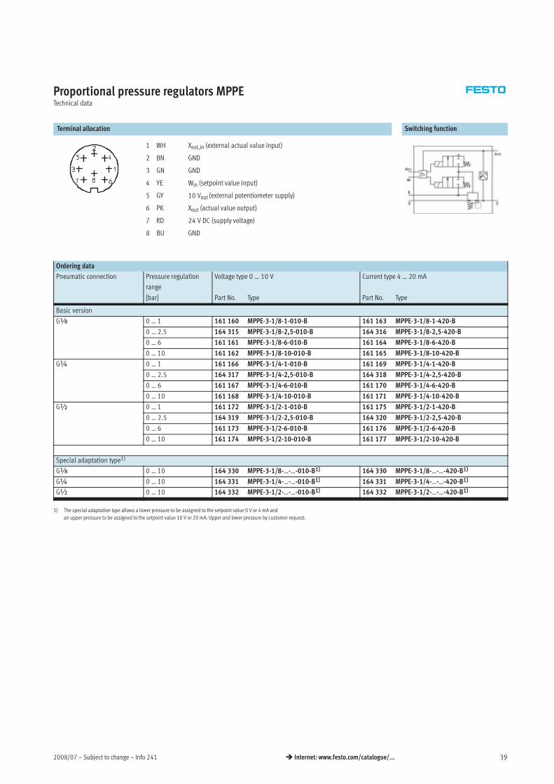
Proportional pressure regulators MPPETechnical data
Terminal allocation Switching function
1 WH Xext,in (external actual value input)
2 BN GND
3 GN GND
4 YE Win (setpoint value input)
5 GY 10 Vout (external potentiometer supply)
6 PK Xout (actual value output)
7 RD 24 V DC (supply voltage)
8 BU GND
Ordering data
Pneumatic connection Pressure regulation
range
Voltage type 0 … 10 V Current type 4 … 20 mA
[bar] Part No. Type Part No. Type
Basic version
Gx 0 … 1 161 160 MPPE-3-1/8-1-010-B 161 163 MPPE-3-1/8-1-420-Bx
0 … 2.5 164 315 MPPE-3-1/8-2,5-010-B 164 316 MPPE-3-1/8-2,5-420-B
0 … 6 161 161 MPPE-3-1/8-6-010-B 161 164 MPPE-3-1/8-6-420-B
0 … 10 161 162 MPPE-3-1/8-10-010-B 161 165 MPPE-3-1/8-10-420-B
G¼ 0 … 1 161 166 MPPE-3-1/4-1-010-B 161 169 MPPE-3-1/4-1-420-B¼
0 … 2.5 164 317 MPPE-3-1/4-2,5-010-B 164 318 MPPE-3-1/4-2,5-420-B
0 … 6 161 167 MPPE-3-1/4-6-010-B 161 170 MPPE-3-1/4-6-420-B
0 … 10 161 168 MPPE-3-1/4-10-010-B 161 171 MPPE-3-1/4-10-420-B
G½ 0 … 1 161 172 MPPE-3-1/2-1-010-B 161 175 MPPE-3-1/2-1-420-B½
0 … 2.5 164 319 MPPE-3-1/2-2,5-010-B 164 320 MPPE-3-1/2-2,5-420-B
0 … 6 161 173 MPPE-3-1/2-6-010-B 161 176 MPPE-3-1/2-6-420-B
0 … 10 161 174 MPPE-3-1/2-10-010-B 161 177 MPPE-3-1/2-10-420-B
Special adaptation type1)
Gx 0 … 10 164 330 MPPE-3-1/8-…-…-010-B1) 164 330 MPPE-3-1/8-…-…-420-B1)
G¼ 0 … 10 164 331 MPPE-3-1/4-…-…-010-B1) 164 331 MPPE-3-1/4-…-…-420-B1)
G½ 0 … 10 164 332 MPPE-3-1/2-…-…-010-B1) 164 332 MPPE-3-1/2-…-…-420-B1)
1) The special adaptation type allows a lower pressure to be assigned to the setpoint value 0 V or 4 mA and
an upper pressure to be assigned to the setpoint value 10 V or 20 mA. Upper and lower pressure by customer request.

Info 241 – Subject to change – 2008/0740 Internet: www.festo.com/catalogue/...
Proportional pressure regulators MPPESType codes
Basic version
MPPES — 3 — x — 1 — 010
Type
MPPES Proportional pressure regulator with
proportional solenoid
Valve function
3 3-way pressure regulator
Pneumatic connection
x Gx
¼ G¼
½ G½
Pressure regulation range
2 0 … 2 bar
6 0 … 6 bar
10 0 … 10 bar
Setpoint value input
010 Analogue voltage signal
420 Analogue current signal
Special pressure regulation range by customer request
MPPES — 3 — x — 1 — 6 — 010
Type
MPPES Proportional pressure regulator with
proportional solenoid
Valve function
3 3-way pressure regulator
Pneumatic connection
x Gx
¼ G¼
½ G½
Required pressure at 0 V or 4 mA [bar]
Required pressure at 10 V or 20 mA [bar]
Setpoint value input
010 Analogue voltage signal
420 Analogue current signal
2008/07 – Subject to change – Info 241 41 Internet: www.festo.com/catalogue/...
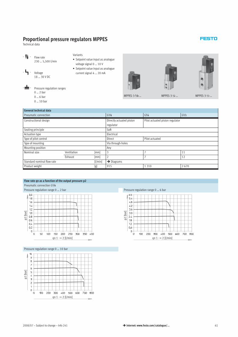
Proportional pressure regulators MPPESTechnical data
-M- Flow rate
230 … 5,500 l/min
-P- Voltage
18 … 30 V DC
-L- Pressure regulation ranges
0 … 2 bar
0 … 6 bar
0 … 10 bar
Variants
• Setpoint value input as analogue
voltage signal 0 … 10 V
• Setpoint value input as analogue
current signal 4 … 20 mA
MPPES-3-x-… MPPES-3-¼-… MPPES-3-½-…
General technical data
Pneumatic connection Gx G¼ G½
Constructional design Directly actuated piston
regulator
Pilot actuated piston regulator
Sealing principle Soft
Actuation type Electrical
Type of pilot control Direct Pilot actuated
Type of mounting Via through-holes
Mounting position Any
Nominal size Ventilation [mm] 3 7 11
Exhaust [mm] 2 7 12
Standard nominal flow rate [l/min] Diagrams
Product weight [g] 915 1 310 2 670
Flow rate qn as a function of the output pressure p2
Pneumatic connection Gx
Pressure regulation range 0 … 2 bar Pressure regulation range 0 … 6 bar
qn 1→ 2 [l/min]
p2[bar]
qn 1→ 2 [l/min]
p2[bar]
Pressure regulation range 0 … 10 bar
qn 1→ 2 [l/min]
p2[bar]

Info 241 – Subject to change – 2008/0742 Internet: www.festo.com/catalogue/...
Proportional pressure regulators MPPESTechnical data
Flow rate qn as a function of the output pressure p2
Pneumatic connection G¼
Pressure regulation range 0 … 2 bar Pressure regulation range 0 … 6 bar
qn 1→ 2 [l/min]
p2[bar]
qn 1→ 2 [l/min]
p2[bar]
Pressure regulation range 0 … 10 bar
qn 1→ 2 [l/min]
p2[bar]
Pneumatic connection G½
Pressure regulation range 0 … 2 bar Pressure regulation range 0 … 6 bar
qn 1→ 2 [l/min]
p2[bar]
qn 1→ 2 [l/min]
p2[bar]
Pressure regulation range 0 … 10 bar
qn 1→ 2 [l/min]
p2[bar]

2008/07 – Subject to change – Info 241 43 Internet: www.festo.com/catalogue/...
Proportional pressure regulators MPPESTechnical data
Operating and environmental conditions
Pressure regulation range [bar] 0 … 2 0 … 6 0 … 10
Operating medium Filtered compressed air, lubricated or unlubricated
Neutral gases
Input pressure 1 [bar] 3 … 4 7 … 8 11 … 12
Max. hysteresis [mbar] 10 50 50
Ambient temperature [°C] 0 … 50
Temperature of medium [°C] 0 … 60
Corrosion resistance class CRC1) 2 2 2*
1) Corrosion resistance class 2 according to Festo standard 940 070
Components requiring moderate corrosion resistance. Externally visible parts with primarily decorative surface requirements which are in direct contact with a surrounding industrial atmosphere or media such as
cooling or lubricating agents.
Response times/step responses to output 2 at p1max [s]
Pressure regulation range
[bar]
0 … 2 0 … 6 0 … 10
Volume to output 2 On1) Off2) On1) Off2) On1) Off2)
0 l Gx 0.220 0.410 0.210 0.280 0.200 0.290
G¼ 0.200 0.890 0.200 0.640 0.200 0.360
G½ 0.220 1.000 0.230 0.660 0.230 0.450
2 l Gx 0.660 2.530 1.200 5.760 1.370 6.300
G¼ 0.200 1.000 0.450 0.760 0.460 0.900
G½ 0.320 1.000 0.340 0.570 0.350 0.630
10 l Gx 2.700 2.800 5.150 24.000 5.800 27.000
G¼ 0.900 2.700 1.500 3.000 1.900 3.400
G½ 0.800 1.400 1.100 1.500 1.300 1.800
1) On = 0 … 90% p2max.2) Off = 100 … 10% p2max.
Electrical data
Pressure regulation range [bar] 0 … 2 0 … 6 0 … 10
Electrical connection Plug, round design to DIN 45 326, M16 x 0.75, 8-pin
Operating voltage range UB [V DC] 18 … 30
Residual ripple 10%
Power consumption Pmax. [W] 20 (at 30 V DC)
Signal setpoint value input Voltage Uw [V DC] 0 … 10g p p
Current Iw [mA] 4 … 20
Signal actual value input Voltage Ux [V DC] 0 … 10g p
Current Ix [mA] 4 … 20
Signal actual value input Voltage Ux,ext. [V DC] 0 … 10g p
external Current Ix,ext. [mA] 4 … 20
Protection class to DIN 60 529 IP65 (with connection socket)
Safety note If the power supply cable is interrupted, output pressure is maintained unregulated.
Protection against polarity
reversal
Setpoint value input
Voltage signal 0 … 10 V
For all electrical connections
Setpoint value input
Current signal 4 … 20 mA
For operating voltage
Protection against short circuit No

Info 241 – Subject to change – 2008/0744 Internet: www.festo.com/catalogue/...
Proportional pressure regulators MPPESTechnical data
Materials
Sectional view
1 Housing Wrought aluminium alloy
2 Diaphragm Nitrile rubber
Dimensions Download CAD data www.festo.com
MPPES-3-x-… MPPES-3-¼-…
MPPES-3-½-…
MPPES-3-¼-…
MPPES-3-½-…
MPPES-3-x-…
Pneumatic connection
D1
B B1 D
∅
H H1 H2 H3 H4 H5 H6 L L1
Gx 77.1 67.1 4.4 116.5 100 55 34 45 23 4 62 34
G¼ 82.1 72.1 4.5 170.2 153.7 63.7 25.3 34.8 13.8 5 62 30
G½ 96.1 86.1 7 227.1 210.6 120.6 53 74 32 18 86 50
1
2
-H- Note
If the power supply cable is
interrupted, output pressure is
maintained unregulated.

2008/07 – Subject to change – Info 241 45 Internet: www.festo.com/catalogue/...
Proportional pressure regulators MPPESTechnical data
Connections Switching function
Terminal allocation MPPES-3-x-… MPPES-3-¼-…/MPPES-3-½-…
1 WH n. c.
2 BN GND
3 GN GND
4 YE Win (setpoint value input)
5 GY n. c.
6 PK Xout (actual value output)
7 RD 24 V DC (supply voltage)
8 BU GND
Ordering data
Pneumatic connection Pressure regulation
range
Voltage type 0 … 10 V Current type 4 … 20 mA
[bar] Part No. Type Part No. Type
Basic version
Gx 0 … 2 187 350 MPPES-3-x-2-010 187 351 MPPES-3-x-2-420x
0 … 6 187 352 MPPES-3-x-6-010 187 353 MPPES-3-x-6-420
0 … 10 187 348 MPPES-3-x-10-010 187 349 MPPES-3-x-10-420
G¼ 0 … 2 187 335 MPPES-3-¼-2-010 187 336 MPPES-3-¼-2-420¼
0 … 6 187 337 MPPES-3-¼-6-010 187 338 MPPES-3-¼-6-420
0 … 10 187 333 MPPES-3-¼-10-010 187 334 MPPES-3-¼-10-420
G½ 0 … 2 187 328 MPPES-3-½-2-010 187 329 MPPES-3-½-2-420½
0 … 6 187 330 MPPES-3-½-6-010 187 331 MPPES-3-½-6-420
0 … 10 187 326 MPPES-3-½-10-010 187 327 MPPES-3-½-10-420
Special adaptation type1)
Gx 0 … 10 187 347 MPPES-3-x-PU-PO-010 187 762 MPPES-3-x-PU-PO-420
G¼ 0 … 10 187 339 MPPES-3-¼-PU-PO-010 187 744 MPPES-3-¼-PU-PO-420
G½ 0 … 10 187 332 MPPES-3-½-PU-PO-010 187 735 MPPES-3-½-PU-PO-420
1) The special adaptation type allows a lower pressure PU to be assigned to the setpoint value 0 V or 4 mA and
an upper pressure PO to be assigned to the setpoint value 10 V or 20 mA. PU and PO by customer request.

Info 241 – Subject to change – 2008/0746 Internet: www.festo.com/catalogue/...
Proportional pressure regulators MPPE/VPPE/MPPESAccessories
Ordering data
Description Cable length Part No. Type
[m]
Connecting cable Technical data Internet: kvia
Connecting cable to the analogue module of valve terminal 5 163 882 KVIA-MPPE-5g g
type 03/04 10 163 883 KVIA-MPPE-10yp /
Plug socket with cable Technical data Internet: sim-m12
Straight, 4-pin, M12x1 5 164 259 SIM-M12-4GD-5-PUg , p ,
Plug socket with cable Technical data Internet: sim-m12
Angled, 4-pin, M12x1 5 164 258 SIM-M12-4WD-5-PUg , p ,
Plug socket with cable Technical data Internet: kmppe
Angled, 8-pin, M16x0.75 2.5 161 879 KMPPE-B-2,5g , p , 75
5 161 878 KMPPE-B-5
Sensor socket Technical data Internet: sie-gd
Straight, 4-pin, M12x1 – 18 494 SIE-GDg , p ,
Sensor socket Technical data Internet: sie-wd
Angled, 4-pin, M12x1 – 12 956 SIE-WD-TR
Angled plug socket Technical data Internet: mppe
Angled, 8-pin, M16x0.75 – 161 839 MPPE-3-B
Push-in fitting Technical data Internet: quick star
For connecting compressed air tubing with standard externalg p g
diameters
Silencer Technical data Internet: u
For fitting in exhaust portsg p
Reducing nipple
–
1) Max. 10 m

2008/07 – Subject to change – Info 241 47 Internet: www.festo.com/catalogue/...
Proportional directional control valves MPYEKey features
General information
• The directly actuated proportional
directional control valve has a
position-controlled spool. This
transforms an analogue input
signal into a corresponding
opening cross-section at the valve
outputs.
• In combination with an external
position controller and displace-
ment encoder, a precise pneumatic
positioning system can be created.
• Flow control function for varying
cylinder speed
• 5/3-way function for varying the
direction of movement
Wide choice of variants
• Setpoint value input
– Analogue voltage signal
– Analogue current signal
• Flow rates from
100 … 2 000 l/min

Info 241 – Subject to change – 2008/0748 Internet: www.festo.com/catalogue/...
Proportional directional control valves MPYEKey features and type codes
Short machine cycle times – fast switching of programmed flow rates
• Reduce machine cycle times by
optimising cylinder speeds
– Assembly technology
– Handling technology
– Furniture industry
A: Proportional valves allow
different speed levels and speed
ramps to be set.
B: Speed regulation with directional
control valves is more difficult
and is performed by means of
exhaust air flow control.
Cylinderspeed
Cylinder stroke
Medium speed
Rapid speed
Creep speed
Flexible cylinder speeds – Achieving variable flow rates
• Flexibly adapting cylinder speeds
to the process. Traversing
individual acceleration ramps
(gentle approach with delicate
goods)
– Automobile suppliers
– Production technology
– Conveyor technology
– Test engineering
Cylinderspeed
Cylinder stroke
Proportional directional control valve as final control element – Dynamic and fast changing of flow rates
• Fatigue tests
• Pneumatic positioning with
SPC200
• SoftStop with end-position
controller SPC11
Cylinderspeed
Time
Type codes
MPYE — 5 — x LF — 010 — B
Type
MPYE Proportional directional control valve
Valve function
5 5/3-way valve
Pneumatic connection
M5 M5
x LF Gx Low Flow
x HF Gx High Flow
¼ G¼
y Gy
Setpoint value input
010 Analogue voltage signal
420 Analogue current signal
Generation
B B series

2008/07 – Subject to change – Info 241 49 Internet: www.festo.com/catalogue/...
Proportional directional control valves MPYEPeripherals overview
1
3
4
6
8
2
7
1
5
2
1
9
Accessories
Brief description Page/Internet
1 Push-in fitting
QS
For connecting compressed air tubing with standard external diameters quick star
2 Silencer For fitting in exhaust ports u
3 Setpoint module
MPZ
For generating 6+1 analogue voltage signals mpz
4 Sensor socket
SIE-WD-TR
Angled, 4-pin, M12x1 53
5 Sensor socket
SIE-GD
Straight, 4-pin, M12x1 53
6 Connecting cable
KMPYE
– 53
7 Connecting cable
KVIA-MPYE
Connecting cable to the analogue module of valve terminal type 03 53
8 Proportional directional control valve
MPYE
– 50
9 Digital input/output For controlling the setpoint module –

Info 241 – Subject to change – 2008/0750 Internet: www.festo.com/catalogue/...
Proportional directional control valves MPYETechnical data
Function
-P- Voltage
17 … 30 V DC
-M- Flow rate
100 … 2 000 l/min
-L- Pressure
0 … 10 bar
Variants
• Setpoint value input as analogue
voltage signal 0 … 10 V
• Setpoint value input as analogue
current signal 4 … 20 mA
General technical data
Pneumatic connection M5 Gx G¼ Gy
Low flow High flow
Valve function 5/3-way, normally closed
Constructional design Piston spool, directly actuated, controlled piston spool position
Sealing principle Hard
Actuation type Electrical
Type of reset Mechanical spring
Type of pilot control Direct
Direction of flow Non-reversible
Type of mounting Via through-holes
Mounting position1) Any
Operating medium Compressed air, filtered (to 5 μm), unlubricated
Nominal size [mm] 2 4 6 8 10
Standard nominal flow rate [l/min] 100 350 700 1 400 2 000
Product weight [g] 290 330 330 530 740
1) If the proportional directional control valve is in motion during operation, it must be mounted at right angles to the direction of movement.
Flow rate q at 6> 5 bar as a function of the setpoint voltage U
Voltage type MPYE-5-…-010-B Current type MPYE-5-…-420-B
q[%]
Uw [V]
q[%]
Iw [mA]

2008/07 – Subject to change – Info 241 51 Internet: www.festo.com/catalogue/...
Proportional directional control valves MPYETechnical data
Electrical data
Pneumatic connection M5 Gx G¼ Gy
Low flow High flow
Power supply [V DC] 17 … 30
Max. current consumption in mid-position [mA] 100p
at full stroke [mA] 1 100
Setpoint value Voltage type [V DC] 0 … 10p
Current type [mA] 4 … 20
Max. hysteresis1) [%] 0.4
Valve mid-position Voltage type [V DC] 5 (±0.1)p
Current type [mA] 12 (±0.16)
Duty cycle2) [%] 100
Critical frequency3) [Hz] 125 100 100 90 65
Safety setting Active mid-position in the event of setpoint value cable break
Protection against polarity Voltage type For all electrical connectionsg p y
reversal Current type For setpoint value
Protection class IP65
Electrical connection 4-pin plug socket, round design, M12x1
1) Referred to the maximum stroke of the piston spool.
2) The proportional direction control valve automatically switches off if it overheats (goes to mid-position) and switches back on once it cools down.
3) Corresponds to the 3dB frequency at the maximum movement stroke of the piston spool.
Operating and environmental conditions
Operating pressure [bar] 0 … 10
Ambient temperature [°C] 0 … 50
Vibration resistance1) To DIN/IEC 68 Parts 2 -6, severity level 2
Continuous shock resistance1) To DIN/IEC 68 Parts 2 -27, severity level 2
CE symbol To 89/336/EEC (EMC regulation)
Temperature of medium [°C] 5 … 40, condensation not permitted*
1) If the proportional directional control valve is in motion during operation, it must be mounted at right angles to the direction of movement.
Materials
Sectional view
1 2 3
1 Housing Anodised aluminium
2 Valve spool Tempered aluminium
3 Housing for electronics Galvanised acrylic butadiene styrene
– Seals Nitrile rubber
Info 241 – Subject to change – 2008/0752 Internet: www.festo.com/catalogue/...
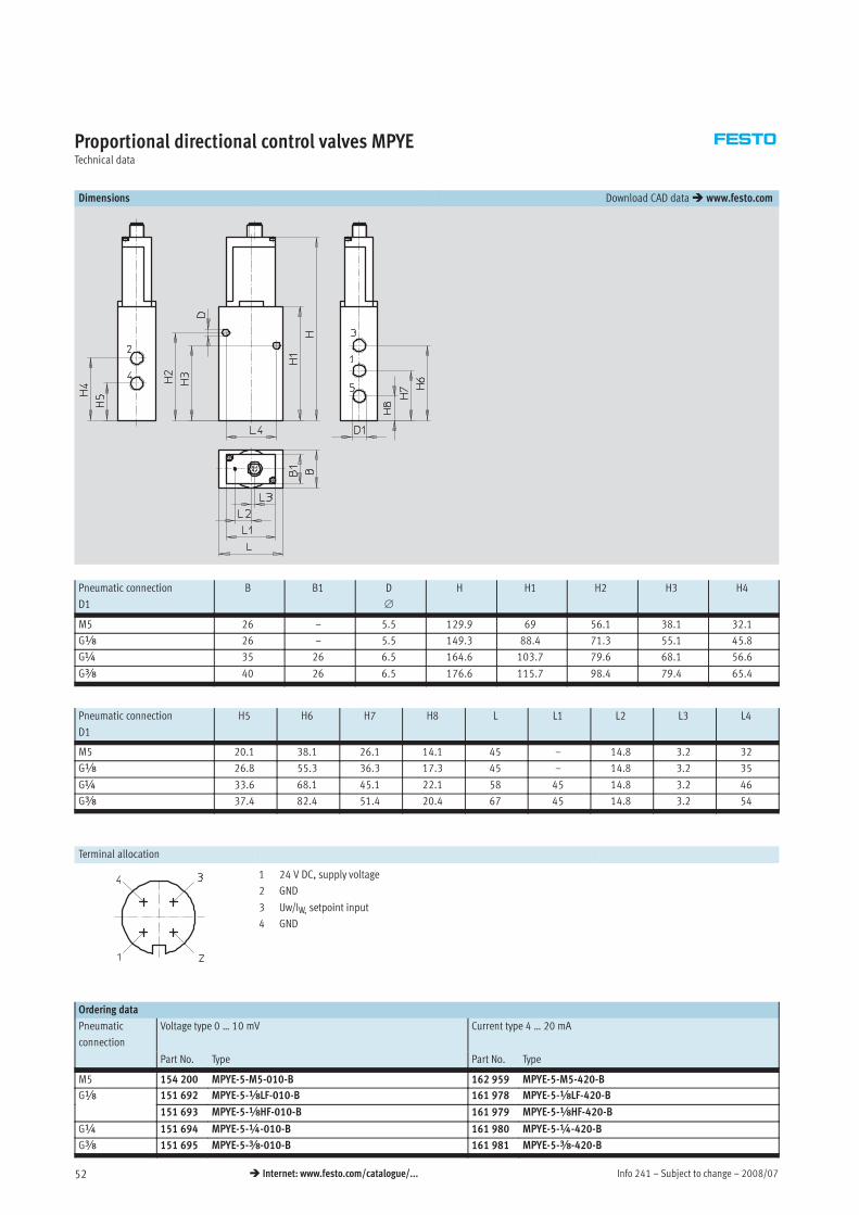
Proportional directional control valves MPYETechnical data
Dimensions Download CAD data www.festo.com
Pneumatic connection
D1
B B1 D
∅
H H1 H2 H3 H4
M5 26 – 5.5 129.9 69 56.1 38.1 32.1
Gx 26 – 5.5 149.3 88.4 71.3 55.1 45.8
G¼ 35 26 6.5 164.6 103.7 79.6 68.1 56.6
Gy 40 26 6.5 176.6 115.7 98.4 79.4 65.4
Pneumatic connection
D1
H5 H6 H7 H8 L L1 L2 L3 L4
M5 20.1 38.1 26.1 14.1 45 – 14.8 3.2 32
Gx 26.8 55.3 36.3 17.3 45 – 14.8 3.2 35
G¼ 33.6 68.1 45.1 22.1 58 45 14.8 3.2 46
Gy 37.4 82.4 51.4 20.4 67 45 14.8 3.2 54
Terminal allocation
1 24 V DC, supply voltage
2 GND
3 Uw/IW, setpoint input
4 GND
Ordering data
Pneumatic
connection
Voltage type 0 … 10 mV Current type 4 … 20 mA
Part No. Type Part No. Type
M5 154 200 MPYE-5-M5-010-B 162 959 MPYE-5-M5-420-B
Gx 151 692 MPYE-5-xLF-010-B 161 978 MPYE-5-xLF-420-Bx
151 693 MPYE-5-xHF-010-B 161 979 MPYE-5-xHF-420-B
G¼ 151 694 MPYE-5-¼-010-B 161 980 MPYE-5-¼-420-B
Gy 151 695 MPYE-5-y-010-B 161 981 MPYE-5-y-420-B

2008/07 – Subject to change – Info 241 53 Internet: www.festo.com/catalogue/...
Proportional directional control valves MPYEAccessories
Ordering data
Description Cable length Part No. Type
[m]
Connecting cable Technical data Internet: kmpye, kvia
Screened 5 151 909 KMPYE-5
X length1) 151 910 KMPYE-…
Connecting cable to the analogue module of valve terminal
type 03
5 161 984 KVIA-MPYE-5
yp
10 161 985 KVIA-MPYE-10
Connecting cable to the axis interface of the axis controller
SPC200
0.3 170 239 KMPYE-AIF-1-GS-GD-0,3
2 170 238 KMPYE-AIF-1-GS-GD-2
Sensor socket Technical data Internet: sie-gd
Straight, 4-pin, M12x1 – 18 494 SIE-GDg , p ,
Sensor socket Technical data Internet: sie-wd
Angled, 4-pin, M12x1 – 12 956 SIE-WD-TR
Push-in fitting Technical data Internet: quick star
For connecting compressed air tubing with standard externalg p g
diameters
Silencer Technical data Internet: u
For fitting in exhaust portsg p
Reducing nipple
–
1) Max. 10 m
Info 241 – Subject to change – 2008/0754 Internet: www.festo.com/catalogue/...
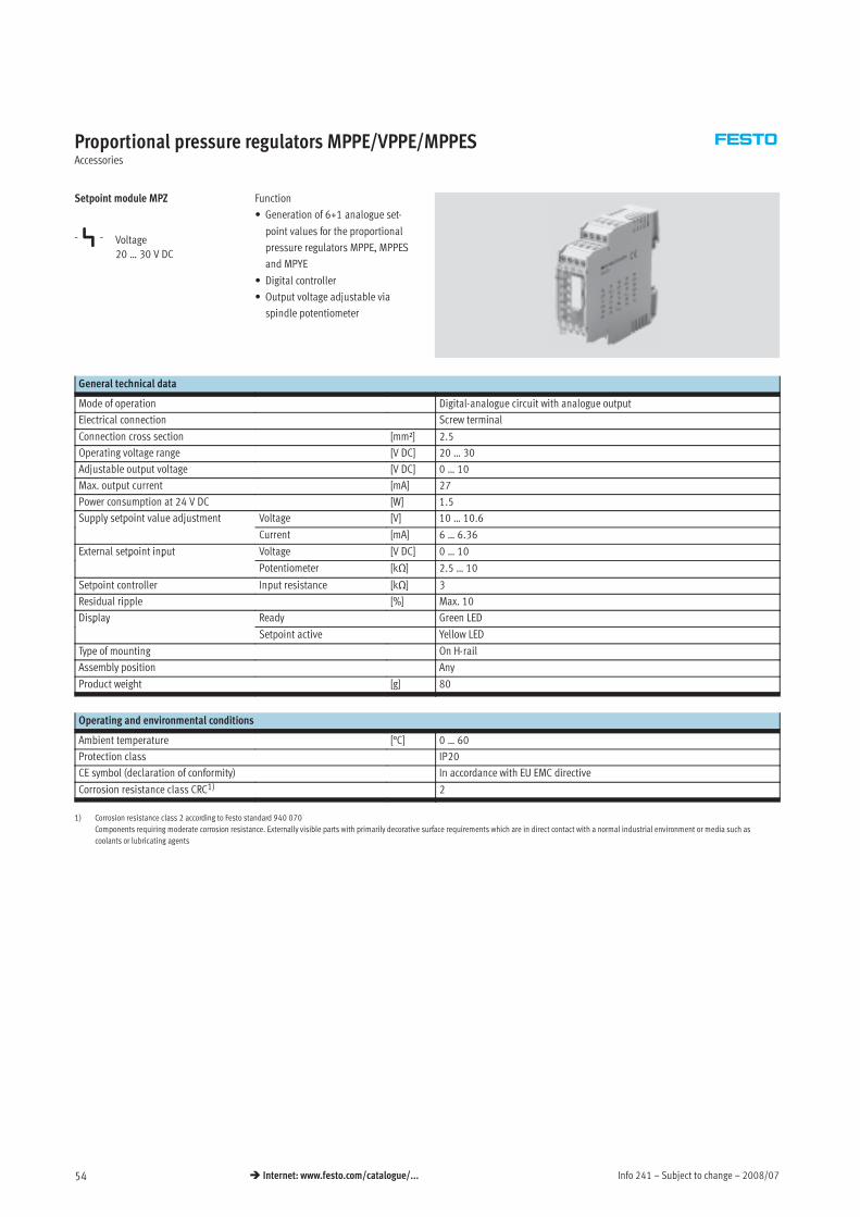
Proportional pressure regulators MPPE/VPPE/MPPESAccessories
Setpoint module MPZ
-P- Voltage
20 … 30 V DC
Function
• Generation of 6+1 analogue set-
point values for the proportional
pressure regulators MPPE, MPPES
and MPYE
• Digital controller
• Output voltage adjustable via
spindle potentiometer
General technical data
Mode of operation Digital-analogue circuit with analogue output
Electrical connection Screw terminal
Connection cross section [mm²] 2.5
Operating voltage range [V DC] 20 … 30
Adjustable output voltage [V DC] 0 … 10
Max. output current [mA] 27
Power consumption at 24 V DC [W] 1.5
Supply setpoint value adjustment Voltage [V] 10 … 10.6pp y p j
Current [mA] 6 … 6.36
External setpoint input Voltage [V DC] 0 … 10p p
Potentiometer [kΩ] 2.5 … 10
Setpoint controller Input resistance [kΩ] 3
Residual ripple [%] Max. 10
Display Ready Green LEDp y
Setpoint active Yellow LED
Type of mounting On H-rail
Assembly position Any
Product weight [g] 80
Operating and environmental conditions
Ambient temperature [°C] 0 … 60
Protection class IP20
CE symbol (declaration of conformity) In accordance with EU EMC directive
Corrosion resistance class CRC1) 2
1) Corrosion resistance class 2 according to Festo standard 940 070
Components requiring moderate corrosion resistance. Externally visible parts with primarily decorative surface requirements which are in direct contact with a normal industrial environment or media such as
coolants or lubricating agents

2008/07 – Subject to change – Info 241 55 Internet: www.festo.com/catalogue/...
Proportional pressure regulators MPPE/VPPE/MPPESAccessories
Connections and control elements
Connections Priority 1 Operational status display,1 p p y,
31 Activate setpoint 1 SP1 1 (highest) green LED
232 Activate setpoint 2 SP2 2 2 Setpoint display active
( )33 Activate setpoint 3 SP3 3 (SP1 … SP6), yellow LED
3 S i i34 Activate setpoint 4 SP4 4 3 Setpoint potentiometer
S S35 Activate setpoint 5 SP5 5 SP1 … SP6
4 I i i l b l11 Activate setpoint 6 SP6 6 4 Inscription label
13 Control line 0 V –
21 Control line 0 V –
22 External setpoint input Uw, in= 0 … 10 V DC 7 (lowest)
23 Control line 10 V DC –
24 Screening PE –
41 Control line 0 V DC –
42 Setpoint output Uw, out –
43 Power supply – –
45 Power supply + –
Dimensions Download CAD data www.festo.com
1 H-rail to DIN EN 60715
Ordering data
Description Part No. Type
Setpoint module for generating 6 + 1 analogue voltage signals 546 224 MPZ-1-24DC-SGH-6-SW
Info 241 – Subject to change – 2008/0756 Internet: www.festo.com/catalogue/...
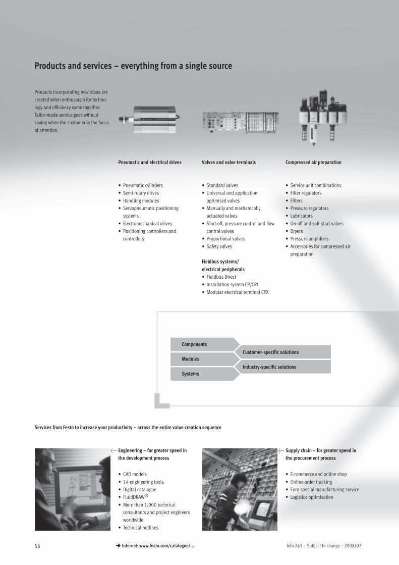
Products and services – everything from a single source
Products incorporating new ideas are
created when enthusiasm for techno-
logy and efficiency come together.
Tailor-made service goes without
saying when the customer is the focus
of attention.
Pneumatic and electrical drives Valves and valve terminals Compressed air preparation
• Pneumatic cylinders
• Semi-rotary drives
• Handling modules
• Servopneumatic positioning
systems
• Electromechanical drives
• Positioning controllers and
controllers
• Standard valves
• Universal and application-
optimised valves
• Manually and mechanically
actuated valves
• Shut-off, pressure control and flow
control valves
• Proportional valves
• Safety valves
Fieldbus systems/
electrical peripherals
• Fieldbus Direct
• Installation system CP/CPI
• Modular electrical terminal CPX
• Service unit combinations
• Filter regulators
• Filters
• Pressure regulators
• Lubricators
• On-off and soft-start valves
• Dryers
• Pressure amplifiers
• Accessories for compressed air
preparation
Components
Modules
Systems
Customer-specific solutions
Industry-specific solutions
Services from Festo to increase your productivity – across the entire value creation sequence
< Engineering – for greater speed in
the development process
< Supply chain – for greater speed in
the procurement process
• CAD models
• 14 engineering tools
• Digital catalogue
• FluidDRAW®
• More than 1,000 technical
consultants and project engineers
worldwide
• Technical hotlines
• E-commerce and online shop
• Online order tracking
• Euro special manufacturing service
• Logistics optimisation

2008/07 – Subject to change – Info 241 57 Internet: www.festo.com/catalogue/...
Gripping and vacuum technology Sensors and monitoring units Controllers/bus systems Accessories
• Vacuum generators
• Vacuum grippers
• Vacuum security valves
• Vacuum accessories
• Standard grippers
• Micro grippers
• Precision grippers
• Heavy-duty grippers
• Proximity sensors
• Pressure and flow sensors
• Display and operating units
• Inductive and optical proximity
sensors
• Displacement encoders for
positioning cylinders
• Optical orientation detection and
quality inspection
• Pneumatic and electropneumatic
controllers
• Programmable logic controllers
• Fieldbus systems and accessories
• Timers/counters
• Software for visualisation and data
acquisition
• Display and operating units
• Pipes
• Tubing
• Pipe connectors and fittings
• Electrical connection technology
• Silencers
• Reservoirs
• Air guns
All in all, 100% product and service quality
A customer-oriented range with unlimited flexibility:
Components combine to produce ready-to-install modules and
systems. Included in this are special designs – since at Festo, most
industry-specific products and customer-specific solutions are based
on the 23,000 plus catalogue products. Combined with the services
for the entire value creation sequence, the end result is unbeatable
economy.
< Assembly – for greater speed in the
assembly/commissioning process
< Operation – for greater speed in the
operational process
• Prepack
• Preassembly
• Turnkey pneumatics
• Handling solutions
• Spare parts service
• Energy saving service
• Compressed air consumption
analysis
• Compressed air quality analysis
• Customer service

Info 241 – Subject to change – 2008/0758 Internet: www.festo.com/catalogue/...
What must be observed when using Festo components?
Specified limit values for technical
data and any specific instructions
must be adhered to by the user in
order to ensure recommended operat-
ing conditions.
When pneumatic components are
used, the user shall ensure that they
are operated using correctly prepared
compressed air without aggressive
media.
When Festo components are used in
safety-oriented applications, the user
shall ensure that all applicable
national and local safety laws and
regulations, for example the machine
directive, together with the relevant
references to standards are observed.
Unauthorised conversions or modifi-
cations to products and systems from
Festo involve a safety risk and are
thus not permissible.
Festo does not accept any liability for
resulting damages.
You should contact Festo’s advisors if
one of the following apply to your
application:
• The ambient conditions and condi-
tions of use or the operating me-
dium differ from the specified
technical data.
• The product is to perform a safety
function.
• A risk or safety analysis is required.
• You are unsure about the product’s
suitability for use in the planned
application.
• You are unsure about the product’s
suitability for use in safety-oriented
applications.
All technical data applies at the time
of going to print.
All texts, representations, illustrations
and drawings included in this cata-
logue are the intellectual property of
Festo AG & Co. KG, and are protected
by copyright law.
All rights reserved, including transla-
tion rights. No part of this publication
may be reproduced or transmitted in
any form or by any means, electronic,
mechanical, photocopying or other-
wise, without the prior written per-
mission of Festo AG & Co. KG. All
technical data subject to change
according to technical update.