Embed Size (px)
Citation preview

Proper Belt Tensioning
Tensioning MechanismThe tensioning mechanism on the Thingomatic is the motor mount. Instead of holes, there areslots where the motor is mounted. This allows the motor to move in a direction parallel to theaxis. To loosen or tighten the belt, loosen the bolts on the motor and slide it towards or awayfrom the stage. When you are satisfied, tighten the motor bolts back down.
This may be a bit tricky on the X motor, and you will need to take the top plate off the Y carriagein order to get access to the bolts.
Tensioning beltsIn general, belts should be tight enough to minimize slack, but not so tight that they start placinga lot of stress on the motor shaft or pulleys. Once a belt is on, turn the motor pulley with yourfingers to gauge if there's too much resistance. If the belt makes an audible noise when you'pluck' it with your fingers, it is too tight. The Thingomatic operation should be nearly silent. Ifyour motor makes a humming or buzzing noise, your belts may be too tight.
To test if your belt is too loose, rotate the motor pulley back and forth by hand. If the stagemoves back and forth in sync, then you are okay. If it lags behind, the belt is too loose. A moreconclusive test is to print a cylinder from Thingiverse on your Thingomatic. If any of the sidesare flattened, then the belt on the corresponding axis is too loose.

Testing Your Bot
Connect to your bot
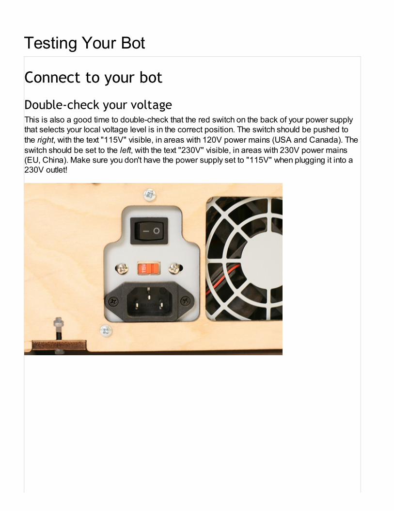
Double-check your voltageThis is also a good time to double-check that the red switch on the back of your power supplythat selects your local voltage level is in the correct position. The switch should be pushed to
the right, with the text "115V" visible, in areas with 120V power mains (USA and Canada). The
switch should be set to the left, with the text "230V" visible, in areas with 230V power mains(EU, China). Make sure you don't have the power supply set to "115V" when plugging it into a230V outlet!

Plug in the power and turn it onFind the black power cord provided in the kit. Plug one end into the power supply on the leftside of your machine and the other end into a wall socket. Flip the switch on the power supplyto ON. The fan on the power supply should start up.
Plug In USB and ConnectTake the included USB A to B cable and plug one end into the Arduino MEGA on the right side

of your bot. Plug the other end into your computer. Next, open up the ReplicatorG program thatyou installed in the very first step.
First, select the appropriate Machine -> Driver -> Thingomatic driver for your build platform. Ifyou've just built a MK6-equipped bot, make sure that you select on of the options with "MK6" inthe title — otherwise your stepper motor won't move correctly.
Now, you'll need to find the correct serial port that your machine has registered as. You can seea list of connected serial ports in the Machine -> Serial Port submenu. If your computer doesn'thave a built-in serial port, you may only see one entry; if you're using a desktop with built-inserial ports, you'll probably see several entries. The way a Thing-O-Matic appears in this menudepends on the platform you're running on. On Windows machines, it may appear as "COM3:".On Linux machines it often appears as "/dev/ttyUSB0". Macs will see multiple entries for eachserial port, with a unique ID associated with each physical connection. The entry you'll want tochoose on a Mac is one of the form "/dev/tty.usbserial-XXX", where XXX is a unique identifier.
After you select a serial port, ReplicatorG will try to connect. (If you've got the "Automaticallyconnect on startup" option unchecked in the preferences panel, you'll may need to press the

'Connect' icon on the right side of the button bar to tell ReplicatorG to connect.) The status barshould turn green, as shown. The console window below should list both a Motherboard
and Firmware version.
If the console window reports that the motherboard can not connect to the toolhead, make sureyour patch cable is connected between the motherboard and extruder controller, that theextruder controller is plugged into the power supply, and that the power on the Thing-O-Matic isswitched on.
Step 3: Open your Control PanelOpen the control panel by selecting the Machine -> Control Panel.

You should be presented with this window.
Testing Your AxesThe first step to testing your bot is to verify that all of your stepper motors are working. Theseare the motors that move your bot around, and if they don't move, then you don't print. First,

there is some information you need to know about your XYZ axes configuration.
Get to know your axes
The Thing-O-Matic moves along three axes: the X axis, the Y axis, and the Z axis. The X axis isthe one that runs from left to right; the Y axis is the one that runs towards and away from you.(Think of these as being like the X and Y axis of a graph, seen from above.) The Z axis goes upand down.
Spend a moment to familiarize yourself with the directions of the axes. It will save you a lot offrustration later!
XY Axes and Relative MotionLook closely at the picture above. On first glance, the X and Y axes may look backwards toyou. Moving the X axis in the negative direction means moving it to the right. The reason for thisis what we call Relative Motion. To be specific, we're talking about the motion of the extruder
nozzle relative to the build surface.
Imagine for a second you are a tiny little person that is standing on the build surface. You arefacing the back of the machine. Suddenly the build surface you are on moves in the X–direction (to your right). You look up at the extruder nozzle and see that it is (from yourperspective) moving to the left. The relative motion of the nozzle to the build surface that hasbeen achieved is a movement in the negative direction.

When you look at the control panel in ReplicatorG, you'll see the "X+" button is on the right.
When you click it to move the platform, though, you'll see the platform move to the left. This is
expected! The controls in ReplicatorG indicate the relative motion of the extruder, not the
motion of the platform.
First Axis MovementWARNING: MAKE SURE YOUR PLATFORM IS CENTERED IN THE MACHINE BEFORE
YOU BEGIN. You don't want to jam your axes into the sides on your first run! The XY axes can
be moved by hand, and the Z axis can be raised/lowered by rotating the drive screw.
Do not force the axis movement! If you clicked one of the buttons, the stepper driver for thataxis remains active in 'holding mode'. This means it will fight you to keep the axis in the place itcurrently is. To turn the motor off, click the 'Disable Steppers' button.
Now it's time for your bot to take its first baby steps. On the left side of the control panel, thereare buttons labeled X+, X–, Y+, Y–. These buttons when pressed will tell your Thing-O-Matic tomove the extruder head in these directions. Remember: this movement is movement of theextruder head relative to the build surface!
Test that your MakerBot moves each axis in both directions. The table below tells you whatdirection each button should move each axis:
Button Movement Seen From Front
X+ platform moves to your LEFT
X– platform moves to your RIGHT
Y+ platform moves TOWARDS you
Y– platform moves AWAY from you
Z+ nozzle moves UP
Z– nozzle moves DOWN
If an axis is moving the wrong way there are two ways to fix this:
1. Shut down ReplicatorG. Turn off the machine, unplug it from both the wall and the USBconnection, open the electronics bay, and rotate the stepper connector 180 degrees.This will invert it.
2. Or, you can invert it in software by going to Machine -> Onboard Preferences and clickingthe appropriate button to invert that axis.
Secondly, you are looking to make sure that each axis moves nice and smoothly. It shouldmake a humming noise, but any grinding noise or a lack of movement means something iswrong.
If you're having trouble with your stepper motion, take a look at the Thing-O-Matictroubleshooting page.

Crank up the speedThere are sliders underneath the movement buttons labeled XY Feedrate and Z feedrate.These set the speed of the axis movements. You can either gradually increase these or dragthem all the way over. Once you do, repeat the back and forth movements from before. Theaxis should continue to move nicely, except this time at maximum speed.
If you're having trouble with your stepper motion, take a look at the Thing-O-Matictroubleshooting page.
Test Your EndstopsThere are 3 endstops provided in your Thing-O-Matic kit. They are used to detect when yourThingomatic has reached a certain point, which allows your machine to automaticallydetermine where it is from any position and automatically start printing in the same spot, even ifsomething went wrong.
Step 1: Trigger Each Endstop By HandThe endstop is a simple mechanical switch. Press it down and you'll hear a nice, satisfyingclick. If everything works right, you'll also see the little LED on the endstop turn on as well.
If the LED does not turn on, you probably have a wiring problem. Check the electronicsinstallation page and make sure you hooked it up right.
Step 2: Trigger Each Endstop By Machine - ManuallyClick the 'Disable Steppers' button in the control panel. We'll be moving the axes by hand firstto make sure they all can actually reach their endstops.

One by one, move each axis to its appropriate endstop. Do not touch the endstop itself, butrather move the axis so that it triggers the endstop. The endstop should light up like it didabove.
If any axis is unable to trigger its endstop, make sure there are no obstacles and try it again. Ifthere are obstacles, make sure they are permanently out of the way, otherwise it could causeproblems during printing.
Step 3: Test Each Endstop For Correct WiringMove each axis to the opposite side of its movement from the endstop. Next, turn the speed foreach axis down to about 500 for XY and 100 for Z. You will be moving each axes towards itsendstops, and triggering the endstops with your finger (or some other object).
Test each axis in sequence by holding down the appropriate endstop and pressing thecorresponding button for that axis (X–, Y–, and Z+). The axis should not move while the endstopis triggered.
If this does not work, you most likely have the endstops plugged into the wrong headers on themotherboard. This is a simple mistake to fix, so open up the electronics bay and make surethey are plugged into the right headers.
Step 4: Home Each AxisThis is the final test: can the machine automatically move itself to the home position for eachaxis? At the top of the Control Panel, there is a 'Homing' menu. Under this menu there are avariety of options that will automatically 'Home' your axes. Homing is the process of movingtowards an axis until it hits the switch.
Select the menu option to home each axis in turn: X–, Y–, and Z+. At the end, each axis shouldbe in its appropriate spot, and the machine should be stopped and silent. If it is grinding oneaxis into a wall, then you need to power off your machine, and start from the beginning of theendstop instructions.
Don't forget to disable your stepper motors: when they get energized they will generate heatand make your motors hot. Turn them off by clicking the 'Disable Steppers' button.
Test Your ExtruderNow your steppers are working, it's time to test your extruder. The extruder testing is prettysimple: you need to make sure everything reports the right temperature, that everything heatsup, and that all the motors move in the right direction. Follow the step by step directions andyou'll be extruding in no time flat.
All of these instructions will focus on the right half of the control panel which deals with theextruder.
Temperature Measurement CheckFirst things first: check the temperature readings. These will be in the greyed out 'Current
Temperature' boxes. If you are using the automated build platform, you'll need to check that too.The temperature readings are in Celsius. Since the extruder is off and cold, it should bereading room temperature. Depending on your location and season, that should be somethingaround 21°C.
If your temperature is wildly different from that, then you probably hooked up the wires in thewrong direction. Re-read the Electronics Installation page and double check your wireorientation.
Turn Up The HeatYou should only do this step once your temperature sensors are working! Otherwise BADTHINGS may happen.
To repeat, NEVER OPERATE THE HEATER if the reported temperature is anything other
than room temperature, usually around 20°C.
First, start off with a low temperature of 50°C. This will allow us to make sure the temperaturesensors are truly working. Enter the value into the 'Target Temperature' field. You must tab outor click out of the field for the change to be sent to the machine.
Now, peek into your Thing-O-Matic. There are tiny little LEDs next to each MOSFET. It's a bittricky to see, but the one near the heater wires should have turned on.
The real test is to wait 10–15 seconds for the temperature to start rising. It should start aconsistent up-slope towards 50°C.
Note: If the temperature starts steadily decreasing, quickly set the target temperature to 0. It
means that you've hooked up your thermocouple backwards! You definitely don't want that. Ifyou see a temperature reversal, you need to shut down the machine, open up the case, andreverse the thermocouple wires.
If you have an automated build platform, test it separately. It should heat up much more quicklyas it has a lower thermal mass.
Turn it All the Way UpNow that your temperature is reporting properly, turn each one up to operating temperature.That is 220°C for the extruder, and 120°C for the heated build surface.
It will take about 5–10 minutes for them to fully heat up and equalize. During that time, theextruder may give off a wee bit of smoke. That is completely normal and is the result of the oilsfrom the anti-sieze burning off. It's a good idea to open a window to let it dissipate.
Control Your Motor SpeedIn the meantime, it's time to test your motor! The speed should be set to the default, 1.98.Leave the duration at 10 seconds for the tests (unless you're feeling particularly impatient ormeticulous.)

If you're running a MK5 extruder, enter a value of 255 (maximum speed) into the Motor Speed(PWM) field. Tab away from it, and ReplicatorG will now tell your motor what speed it shouldrun at when you turn it on.
Move Your Motor Back and ForthNext, press the 'Forward' button next to 'Motor Control'. You should hear your motor turn on, andif you visually inspect it from the front, you should see the motor shaft rotating clockwise. Clickthe reverse button and it should move in the other direction.
If your motor is rotating counter-clockwise in Forward, first double check that you have pressedthe 'Forward' button. :) If the Forward button is pressed, that means the motor wires arereversed. Now you need to turn off your machine, open up the electronics bay, and switch themotor wires. This fix works for both DC and stepper motors.
Test Your Conveyor Belt MotorNote: On Mk6/Mk7 extruders, this will turn the extruder fan on and off. The conveyor motor iscontrolled by the extruder board on newer ABP.
If you are using the Automated Build Platform, you'll want to test the motor that drives theconveyor belt. Click the 'Build platform belt' checkbox at the very bottom of the ControlPanel.
The motor should whir into life, and your conveyor belt should move with it. The direction of thebelt should be towards the front (and the ramp at the front).
If it is not moving at all, or moving in the wrong direction, go back to the electronics wiring stepand double check everything. You'll have to turn off the machine and open up the electronicsbay for this.
First ExtrusionIf everything went according to plan, you should now have your speed set to 1.98 rpm (or aPWM setting of 255 for MK5 users), and your extruder temperature hovering around 220°C. If ithas not hit 220°C yet, give it some time. If it has been hovering just below 220°C, bump up thetemperature to 225°C for now and you'll need to adjust the PID settings to get it just right.
Make sure your plunger is loosened all the way so you can push the filament in yourself. Takesome 3mm filament, and insert it into the extruder, and push it all the way down. If you keeppressing it, you should be able to manually extrude some plastic. Awesome!
Now is time to tighten down the filament plunger. Make it finger tight so the filament is pressedup against the drive gear. Make sure you're at 220°C, and turn your motor on Forward. Thefilament should begin to be pulled into the extruder, and it should also start extruding.
Plastic is cheap, so let it extrude for at least a couple minutes to 'break in'. Don't get tooexcited and jump the gun just yet. Make sure it all works properly before going to the next step.

Turn off the HeatThe next step requires a bit of calibration and will take at least 5–10 minutes. It's not a goodidea to have your extruder on and hot, so turn it off for now. You can do this by setting thetemperature to 0, and clicking the stop motor button.
Thingomatic - How To Print
Level Your Build PlatformIn order for your prints to be successful, you need a build surface that is level relative to extrudernozzle. The vast majority of the time, this will just happen as a result of building your machine.Occasionally, you will need to adjust it to make it nice. The flatness of your build surface reallyonly needs to be about +/- 0.5mm due to the 'raft' that will be printed as the first layer. This raftwill make up for many irregularities in your build surface.
The basic process is pretty simple:
1. Manually lower your extruder so that it is roughly 1mm above the middle of the platform.2. Move the build platform so that each corner is under the extruder nozzle in sequence.
Note the relative gap height between each corner and the middle.3. Adjust the height of each corner to compensate for the non-levelness.
Acrylic Build Platform or Heated Build platformLeveling the acrylic build platform is very simple. You can loosen the top nuts and adjust themiddle nut to move each corner up or down. When you're done, lock the bottom and middlenuts against each other to keep it in place. Do this for all 4 corners and you're done.
Automated Build PlatformThe automated build platform does not have a leveling procedure. It your ABP is not quite level,use some 'shims' such as pieces of paper or washers to adjust the height of the ABP platform.
In this picture a plastic washer is used to raise one corner the platform.

Automatically set your Z-heightCheck out this video of the process!
The process for setting your Thing-O-Matic's Z-height has been streamlined with the release ofReplicatorG 25. You no longer need to use a text editor to make changes to the Gcode

profiles.
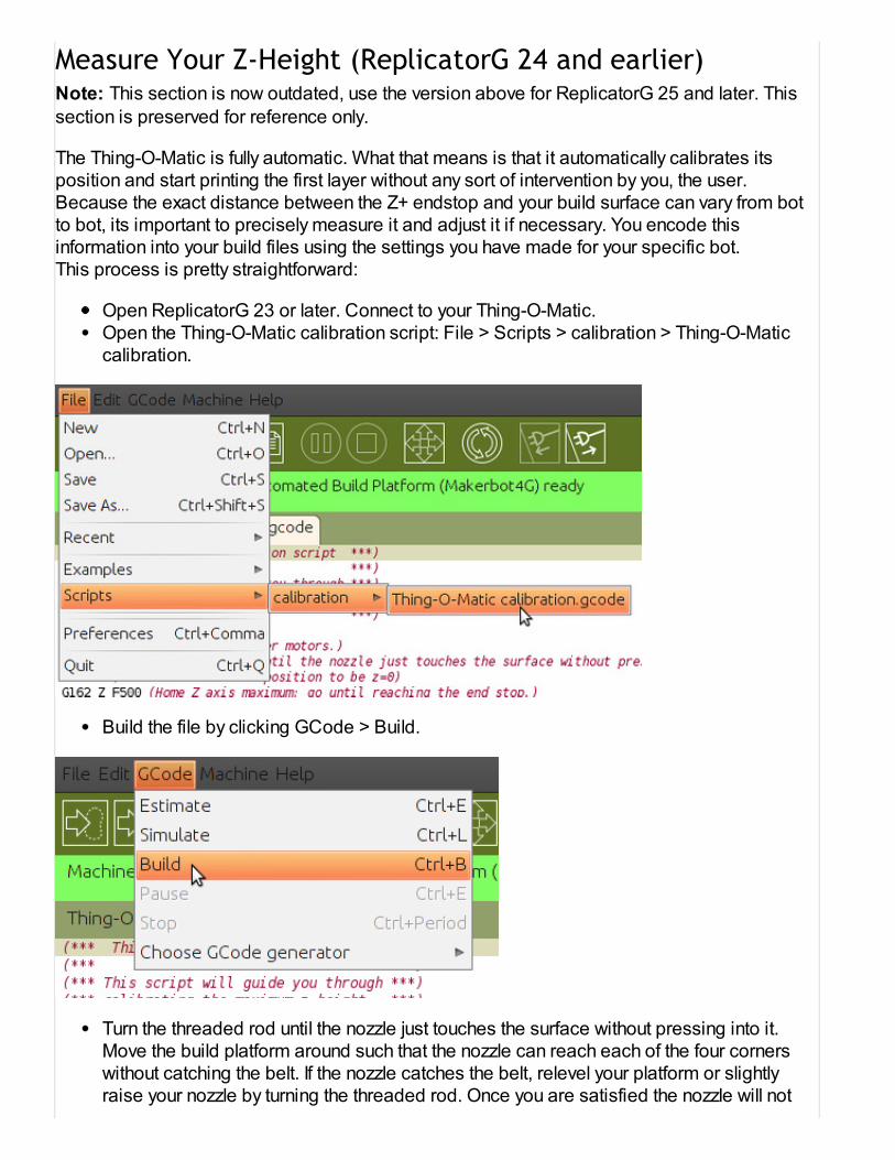
Open the Thing-O-Matic calibration script: File > Scripts > calibration > Thing-O-Maticcalibration.
Build the file by clicking GCode > Build.
Turn the threaded rod until the nozzle just touches the surface without pressing into it.Move the build platform around such that the nozzle can reach each of the four cornerswithout catching the belt. If the nozzle catches the belt, relevel your platform or slightlyraise your nozzle by turning the threaded rod. Once you are satisfied the nozzle will notcatch on the belt, click Okay.
Your machine will now save your Z-height to the motherboard's onboard memory, and you canuse the profiles included with ReplicatorG 25 or the new Print-O-Matic method.
You can now go ahead to the section titled "Get a 3d Model."
Measure Your Z-Height (ReplicatorG 24 and earlier)Note: This section is now outdated, use the version above for ReplicatorG 25 and later. This
section is preserved for reference only.
The Thing-O-Matic is fully automatic. What that means is that it automatically calibrates itsposition and start printing the first layer without any sort of intervention by you, the user.Because the exact distance between the Z+ endstop and your build surface can vary from botto bot, its important to precisely measure it and adjust it if necessary. You encode thisinformation into your build files using the settings you have made for your specific bot.This process is pretty straightforward:
Open ReplicatorG 23 or later. Connect to your Thing-O-Matic.Open the Thing-O-Matic calibration script: File > Scripts > calibration > Thing-O-Maticcalibration.
Build the file by clicking GCode > Build.
Turn the threaded rod until the nozzle just touches the surface without pressing into it.Move the build platform around such that the nozzle can reach each of the four cornerswithout catching the belt. If the nozzle catches the belt, relevel your platform or slightlyraise your nozzle by turning the threaded rod. Once you are satisfied the nozzle will not

catch on the belt, click Okay.
When the Z platform stops moving click Okay.
Open the control panel and find "Z Position". This is the "Z axis maximum". This shouldhave a value of approximately 107, each maching being slightly different. Record thisvalue for the next step.
Select GCode GeneratorWe highly recommend using Skeinforge 35.
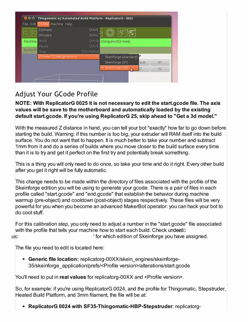
Adjust Your GCode ProfileNOTE: With ReplicatorG 0025 it is not necessary to edit the start.gcode file. The axis
values will be save to the motherboard and automatically loaded by the existing
default start.gcode. If you're using ReplicatorG 25, skip ahead to "Get a 3d model."
With the measured Z distance in hand, you can tell your bot *exactly* how far to go down beforestarting the build. Warning: if this number is too big, your extruder will RAM itself into the buildsurface. You do not want that to happen. It is much better to take your number and subtract1mm from it and do a series of builds where you move closer to the build surface every timethan it is to try and get it perfect on the first try and potentially break something.
This is a thing you will only need to do once, so take your time and do it right. Every other buildafter you get it right will be fully automatic.
This change needs to be made within the directory of files associated with the profile of theSkeinforge edition you will be using to generate your gcode. There is a pair of files in eachprofile called "start.gcode" and "end.gcode" that establish the behavior during machinewarmup (pre-object) and cooldown (post-object) stages respectively. These files will be verypowerful for you when you become an advanced MakerBot operator: you can hack your bot todo cool stuff.
For this calibration step, you only need to adjust a number in the "start.gcode" file associatedwith the profile that tells your machine how to start each build. Check under 'GCode >Choose GCode generator …' for which edition of Skeinforge you have assigned.
The file you need to edit is located here:
Generic file location: replicatorg-00XX/skein_engines/skeinforge-
35/skeinforge_application/prefs/<Profile version>/alterations/start.gcode
You'll need to put in real values for replicatorg-00XX and <Profile version>.
So, for example: if you're using ReplicatorG 0024, and the profile for Thingomatic, Stepstruder,Heated Build Platform, and 3mm filament, the file will be at:
ReplicatorG 0024 with SF35-Thingomatic-HBP-Stepstruder: replicatorg-

0024/skein_engines/skeinforge-35/skeinforge_application/prefs/SF35-Thingomatic-HBP-Stepstruder/alterations/start.gcode
If you're using the profile for the Stepstruder with Automated Build Platform and 1.75mmfilament, it will be:
ReplicatorG 0024 with SF35-Thingomatic-ABP-Stepstruder-1.75mm: replicatorg-
0024/skein_engines/skeinforge-35/skeinforge_application/prefs/SF35-Thingomatic-ABP-Stepstruder-1.75mm/alterations/start.gcode
If you're doing advanced, custom stuff like using skeinforge 39, then you'll need to alter the filein the skeinforge-39 folder, but if that's the case, you're probably on top of this already.
Now, open that file with a plain text editor. On Windows, Notepad++ is a nice one. On Mac
or Linux, you can use Bluefish or TextWrangler. In that file, you will see a line that looks like this:
G92 Z80 ( ---=== Set Z axis maximum ===--- )
Change this line so that the Z80 number is your measured Z height number. For example, if thenumber you recorded was 107.2, you will want to modify the line to look like this:
G92 Z107.2 ( ---=== Set Z axis maximum ===--- )
Every time you make a change to this file, you will need to re-slice your model for the changesto take effect.
Be careful, measure it twice and test it carefully.That way you won't end up with bad prints or a damaged belt like this.

Get a 3D ModelYou can either download, design, or 3D scan something to get a 3D model. Downloading isthe easiest, and we have created Thingiverse.com as a place for people to share theirdesigns.
We highly recommend starting off with a known good 3D model for your first print. The 20mmcalibration cube is a great place to start. Download it to your computer, then open it withReplicatorG.
Slice Your 3D ModelSlicing your model is also known as 'generating the toolpath'. What we are doing here istransforming the 3D model into the exact instructions required to build it. These instructions arein the form of GCODE which is an ancient control language for CNC machines. It is very basic,and tells the robot to go from point to point, when to turn the extruder on or off, and many otherthings. ReplicatorG then takes these instructions and then tells them to your Thingomatic whichfollows them and builds you your object.
To slice your object, open it with ReplicatorG, and press the 'Generate GCode' button. Selectthe 'thingomatic-mk5-automated-abs' profile, click the 'Use Raft' checkbox, and then click 'Ok'.
ReplicatorG will now think for a while. Depending on how complex an object is, and how fast

your computer is, this may take a while. This model is fairly simple, so you can expect it to takeanywhere from 1 minute on a fast computer to 5 minutes on a slow computer. Patience is thekey here.
Once it completes the toolpath, you're ready to print.
Print Your 3D ModelWith the Thing-O-Matic, the printing process is totally automated. Click the Build button, orselect 'GCode -> Build' from the main menu. Your MakerBot will go through a warmup routineand then begin building your object. The basic process is this:
Start warming up the heaterHome the X, Y, and Z axesMove to waiting position to finish warming up (may take up to 10 minutes)Extrude for a couple seconds to 'prime the pump'Wipe any 'boogers' that will inevitably have formedStart printing your object.
For the first few prints, it's very important to keep an eye on your printer. It may do somethingweird, or it may have been miscalibrated. Keep one hand on the power switch, and if yousense any sort of danger, flip the switch.
A nice, good looking raft

A raft that is too smooshedIf your raft looks like this, or your nozzle hits the build surface, then your Z height is too large.Decrease the Z-height by an appropriate amount (0.2mm is usually good)
Don't forget to re-slice your object after making this change, otherwise nothing will change. Ifyou do not re-slice, the GCODE that actually makes the printer run will not change, regardlessof the start.txt edit.
A raft that is too high

If your raft looks like this or if it is too far off the build surface and is not sticking, your Z height istoo small. Increase the Z height by an appropriate amount (0.2mm is good here as well.)
Don't forget to re-slice your object after making this change, otherwise nothing will change. Ifyou do not re-slice, the GCODE that actually makes the printer run will not change, regardlessof the start.txt edit.
After the PrintIf you are using the Automated Build Platform, it will wait for 90 seconds to let the part cooldown, and then it will run the conveyor belt to eject the part. Do not remove the part from theconveyor belt by hand. It will do it for you.
When it is done, it will wipe its nozzle and return to 0,0,0 and be ready for another print.
If you are using the Acrylic Build Platform, you will need some sort of scraper to scrape theobject off the surface with. As many CupCake CNC owners can tell you, a sharpened paintscraper works really well! You do not need to wait for the object to cool down, and once itsdone building your object, your machine will shut down.
If you are using the Heated Build Platform, wait at least 90 seconds for your object to cool downand it should very simple to pull off the build surface.

Maintenance and Upkeep
Keep your Bot RunningThe Thing-O-Matic does not require much maintenance. Once you have it built and running, itwill provide you with many hours of hands-off printing. However, some of the Thing-O-Matic'smechanical parts, especially the ones in constant movement, are subject to wear and shouldbe tuned from time to time. The following list are things you should be mindful of while usingyour machine.
Belt TensionIf the belts curve down and the sides flatten, they are likely too loose.
Symptoms of loose belts may include skipped steps, 'backlash' (see below), or infill thatdoesn't reach a printed object's inner shell surface.
When the motor switches directions, there is a certain amount of movement it must do in orderto pick up the slack on the other side before it can actually move the axis. This 'backlash'causes the constructed part to be inaccurate.
For more information on tightening belts, see the proper belt tensioning page.
Keep X,Y, and Z Rods LubricatedIf your machine is very loud and seems to vibrate a lot when moving, you probably need tolubricate the rods.
All three Thing-O-Matic axes rely on 3/8" diameter precision rods to ensure smooth linear travelwithout any wobbling. Adding lubrication will clean the rods, reduce friction and minimize long-term wear on the bushings as they slide along these rods.
Grab a clean rag, apply some lubricant to the rag, and run the rag up and down each rod.

Tighten Your BoltsThe bolts on your machine can vibrate loose over time. This is particularly true on the X, Y, andZ axes. Loose bolts can lead to failures or extra noise. If this happens, take your hex key outand tighten any bolts that feel loose.
Upgrade Your BotOne of the great things about a 3D printer is that it can print its own upgrades, and theMakerbot community is constantly producing designs to improve your bot. You will find a big listof ToM upgrades at http://www.thingiverse.com/thing:6443

Thing-O-Matic Calibration
I need more power, Scotty!Your Thing-O-Matic is already up and running, but you want to bring the print quality to the next level.Follow these tips, and you will be there in no time.
Strong Stepper Motor TorqueIf you've skipped adjusting the pots on your Thing-O-Matic's stepper motor drivers, now is the time tocorrect that. This can cause a really bad issue: losing steps, even when the bot is otherwise correctlyset up.
Losing steps will cause the prints to be oddly shaped and of very poor quality. The obnoxious,grinding noise the stepper motor makes when it can't move is also a telling sign; if this is you,complete the following instructions right now.
Adjusting Stepper Driver PotentiometersThe Generation 4 stepper drivers have four adjustable potentiometers labeled PFD, RC1, REF, andRC2. This allows modularity in the electronics so that stepper motors of all different specs and sizescan be controlled with the same driver. A brief description of what each potentiometer controls can befound on the page about the Stepper Driver v3.3
The pot labeled REF controls current supplied to the motor. This is the most commonly adjusted pot.Do not adjust the others unless you know what you are doing. Conveniently, each pot has a test pointfor measuring with a multimeter. Put the positive probe on the test point, and the negative probe toground.
Note that these values are with the steppers DISABLED, not enabled. 'DISABLED' meansthat you have not activated your stepper motors in ReplicatorG

If you do not have a multimeter, counter clockwise rotation will decrease the value, and clockwise willincrease for REF and PFD — but it's the opposite for RC1 and RC2. There are small indications ofthe total range for each potentiometer engraved in its case. Suggested values for the stock Thing-O-Matic steppers are:
Stepper Motor REF Voltage (V) Rotation between Max and Min
X & Y 0.600 Between 1/8 - 1/4
Z 0.617 Between 1/8 - 1/4
Note: If you set the current too high, the motor will be eventually get too hot to touch.
If your Z axis stepper motor is making high pitched noises while set to the above REF value, then youwill need to change the other potentiometers as well.
Since the motor suppliers have changed over the course of the Thing-O-Matic's lifetime, you first needto identify which motors you have from the image below, and then adjust their respectivepotentiometers accordingly.
The suggested pot values for the Z-axis stepper motors ONLY:
Stepper Motor PFD (V) RC1 (V) REF (V) RC2 (V)
Makerbot Leadscrew Nema17 2.311 0.952 0.617 0.963
Moons Leadscrew Nema17 2.311 0.952 0.617 0.963
The suggested pot values for the X&Y-axis stepper motors ONLY:
Stepper Motor PFD (V) RC1 (V) REF (V) RC2 (V)

Makerbot Nema17 1.952 0.953 0.600 0.955
Moons Nema17 1.952 0.953 1.68 0.955
The suggested pot values for the Stepstruder MK7 stepper motor ONLY:
Stepper Motor PFD (V) RC1 (V) REF (V) RC2 (V)
Stepstruder MK7 1.952 0.953 1.68 0.955
The suggested pot values for the Stepstruder MK6 stepper motor ONLY:
Stepper Motor PFD (V) RC1 (V) REF (V) RC2 (V)
Stepstruder MK6 2.31 0.94 1.56 0.94
For those of you who want to go a little deeper, here's a table that explains a little bit more about theproperties of these motors.
Extruder TemperatureIdeally, the goal is to use the lowest temperature which produces the desired results.
If the temperature is too high, this can lead to drips and sagging lines. These are especiallynoticeable on overhangs. If the temperature is too low, it can lead to poor adhesion, delamination, andedge curling.
By default ReplicatorG 0025 sets the MK6+ Extruder temperature to 225C. However, this willoccasionally need to be adjusted for optimum results. Often, when using a new batch of filament, thetemperature will need to be adjusted. This can be due to variations in the filament diameter, absorbedmoisture levels, and even color used.
3mm ABS Filament by Color Extruder Temp
Natural 225C
Black 230C
Nuclear Green 235C

Note: These are starting points for reference only. Each Thing-O-Matic build and each batch offilament may have individual variations.
Establish Ideal PID SettingsIf the extruder seems to have trouble reaching or maintaining its target extrusion temperature, you mayneed to adjust the heater's control system parameters.
The Thing-O-Matic maintains its operating temperature with a feedback loop, and the PID settings willmathematically control how the system reacts to that feedback. A very detailed explanation of thetheory behind how this works can be found on Wikipedia's article about PID Controllers
Default PID Settings For Plastruder MK5To edit the PID settings, you need to have your machine connected to a computer with ReplicatorGrunning. Under the Machine file menu, select Toolhead Onboard Preferences.
The recommended defaults are listed below:
P : 6.25I : 0.4140625D : 100.0
While the default settings will work well for the vast majority of users, it is still recommended that youverify they are working well. ReplicatorG has made this very easy to do with its built-in TemperatureChart in the control panel.
While in the control panel:
1. Set the Target Temperature (C) field value to 2202. Pressing Enter on the keyboard.
The chart will then display a blue line indicating the target temperature, and for the next couple ofminutes you can watch the red line to see how the extruder heats up. The Temperature chart belowdemonstrates what you want to see:
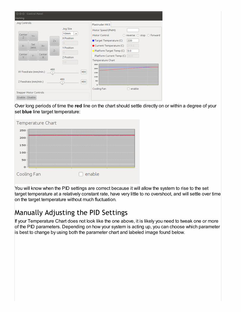
Over long periods of time the red line on the chart should settle directly on or within a degree of yourset blue line target temperature:
You will know when the PID settings are correct because it will allow the system to rise to the settarget temperature at a relatively constant rate, have very little to no overshoot, and will settle over timeon the target temperature without much fluctuation.
Manually Adjusting the PID SettingsIf your Temperature Chart does not look like the one above, it is likely you need to tweak one or moreof the PID parameters. Depending on how your system is acting up, you can choose which parameteris best to change by using both the parameter chart and labeled image found below.

Image via University of Notre Dame Aerospace and Mechanical Engineering
Chart via Wikipedia
The parameter chart describes how each visual characteristic on your Temperature Chart will beeffected by an INCREASE in the P, I, or D parameter.(Labeled Kp,Ki,Kd)
The image labels how these characteristics would be apparent in your Temperature Chart.
For example, if you are not able to reach your set target temperature, the image shows you'll want todecrease the steady-state error, and the parameter chart shows this can be done by either increasingP, or increasing I by a very small amount.
As another example, if you are seeing temperature oscillations by more than a couple degrees aboveand below your target temperature, you'll want to improve stability, and the parameter chart shows usthat this can be resolved in most cases by increasing D.

It is important to understand that this is very much a guess-and-check process, yet you shouldn'tneed to tweak your settings very far away from the defaults. After making a parameter change, it isalways required that the Extruder Board is reset for the changes to take effect.
Improving the Default Skeinforge Model Slicing
ProfileThe default Thing-O-Matic Skeinforge profile that is packaged with ReplicatorG should produce somenice looking parts out of the box, but you want to be certain that your settings are optimized for yourThing-O-Matic.
Basic Tuning ProcessPlease note: this refers to an outdated script. We're working on documenting our new Print-O-Maticfeature in ReplicatorG 25 and beyond! This is here for reference purposes only.
The basic procedure for tuning your skeinforge profile is to change one setting at a time, do a testprint, examine the output, and repeat. There are some quirks to the process, but that is about it.Before you get started, we highly recommend you read this awesome guide by MakerBot OperatorDave Durant. It will help you tremendously.
Paraminator.py - Automated Testing of ParametersThe process above is a fairly intensive process. For every single change, you have to re-slice yourobject, print it, mark it, and then do it all over again. This can be pretty laborious, not to mention theprocess can take many hours.
With the advent of the automated build platform, we can now automate a portion of that process.We've written a script called paraminator.py which allows you to pick one parameter in skeinforge,choose a minimum and maximum value, and it will generate a single gcode file that contains a seriesof prints that each have been sliced with a different value for the chosen parameter.

In order to help you identify the objects after they have printed, the objects to be printed are sequentialblock letters with the embossed letter on top. The idea is that the user looks at the printed letters, anddecides which iteration has the best visual results. Looking back at the gcode, it is specified whichletter block corresponds to each value, and the best performing value can be input into skeinforge.Using this process with any skeinforge parameters in question will allow you to tune you machine tothe max!
How to Use Paraminator.pyCurrently, the paraminator script is only functional via the command line. First verify that"paraminator.py" and the "test-objects" folder are both living in theReplicatorG/skein_engines/skeinforge-35/skeinforge_application directory. The test-objectsfolder should contain 26 letter block stls.
You will also need python to be in your path: this means that if typing "python" doesn't start a pythonprompt (which, btw, can be exited by typing in the command "quit()" if yours works) it will have to beadded. Linux and OS X are probably OK, but windows users will likely need to edit their "EnvironmentVariables" in the "Advanced" section of "System Properties," which can usually be accessed by right-clicking "Computer" or "My Computer" and choosing "Properties." Add the name of the folder wherepython is installed, often C:\Python27 or something similar.
Now decide which setting in skeinforge you would like to explore, and take note of exactly how itappears in skeinforge, and which plug-in it belongs to. For instance, if you want to change the layerthickness, it appears in skeinforge as "Layer Thickness (mm)" (capitalization matters) and it is part ofthe Carve plug-in.
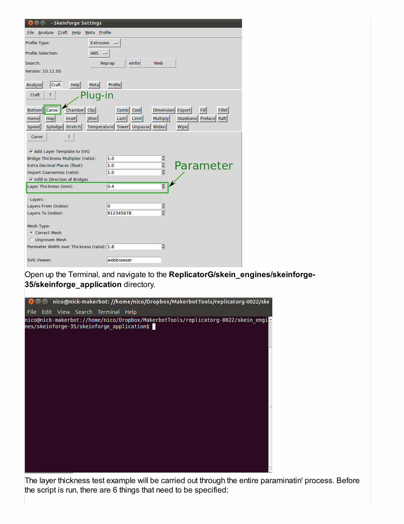
Open up the Terminal, and navigate to the ReplicatorG/skein_engines/skeinforge-35/skeinforge_application directory.
The layer thickness test example will be carried out through the entire paraminatin' process. Beforethe script is run, there are 6 things that need to be specified:

file - this is where you locate the plug-in file. For the example above, the carve.csv file wouldneed to be specified. In skeinforge 35, the csv files are located deeper within theskeinforge_application directory at: prefs/SF35-Thingomatic-ABP/profiles/extrusion/ABS/carve.csv
parameter - this is the parameter that is going to be changed, and it needs to be written withquotations exactly how it appears in skeinforge: "Layer Thickness (mm)"
start - this is the starting value for the parameter you want to explore. It's a good idea to have astarting value below your expected ideal value, so that it will be clear when you reach the idealvalue. For the layer height test, we will choose: 0.32
end - this is the ending value for your parameter. It should be higher than expected. For the layerheight test, we will choose: 0.40
increment - this dictates how many objects will be printed in your test. For the layer height test,if an increment of 0.04 is chosen, it would create 3 objects: 0.32, 0.36, and 0.40. If we were tochoose an increment of 0.02, it would create 5 objects: 0.32, 0.34, 0.36, 0.38, and 0.40. To bethorough, lets choose an increment of 0.01.
output - this is where you specify the file name you want for the test. The output will be a singlegcode file that queues up all the incremental parts into a single print session on the ABP. Theoutput gcode file can also be found in the skeinforge_application directory. For the layer heighttest, we will choose our output name as: ABS-layerheight-test.gcode
Now go back to the terminal, and get ready to execute the paraminator script. The six specificationsabove will all be typed into the command line to execute the script:
python paraminator.py --file=prefs/SF35-Thingomatic-ABP/profiles/extrusion/ABS/carve.csv --parameter="Layer Thickness (mm)" --start=0.32 --end=0.4 --increment=0.01 --output=ABS-layerheight-test.gcode
Note: the "--" above is actually two hyphens
The script will start generating your objects.

The script is finished and you can now open the gcode in ReplicatorG, and start testing! In thebeginning of the gcode, there is a commented out reference table for determining which valuecorresponds with each letter block.

Good luck, and happy paraminating!

How to Print Raftless
OverviewRaftless printing is an advanced technique you can use to reduce waste, improve the quality ofyour parts, and generally improve your MakerBot experience. It can be a bit tricky to setup, butonce you have it working it is simple to use.
The basic strategy of raftless printing is to print the first outline of the first layer at a much slowerspeed than normal. This allows even the most difficult outlines to stick to the build surface.Once the first outline is drawn, the rest of the object is built. Getting the first outline to stick100% is the most critical part of the build and if that fails, then the entire print will fail. It's literallyall or nothing.
Step 1: Create a new ProfileYou will want to be using the latest version of ReplicatorG, and the latest Skeinforge included inReplicatorG. As of this writing, that is ReplicatorG 0023 and Skeinforge 35.
This guide assumes you have a properly calibrated and functioning Skeinforge 35 profile. If youdo not have your printer working nicely with a raft, then you need to do that first. Only attemptthis once you are printing nice models with a raft.
Create a new profile by opening ReplicatorG, opening a 3D model if you need to, and thenclicking the 'Generate GCode' button.
This pulls up the 'Choose a skeinforge profile' window. Select the profile you currently use forslicing, and then click 'Create…'. Give your profile a descriptive name and click 'OK'. TheSkeinforge configuration screen will then pop up to allow you to modify your profile.
Step 2: Enable OutlineSince raftless printing requires a perfect first outline, we've included the Outline plugin inSkeinforge which draws a box around your object for the first layer. This box 'primes the pump'and gets your extruder in the perfect state for printing the first layer.
Click on the Outline button and make sure the 'Activate Outline' box is checked.
You may experience that you obtain best results by disabling the 'Wipe' checkbox in the 'Wipe'panel.
Step 3: Update your Raft settingsRaftless printing is made possible by adjusting the settings in the Raft plugin. We will still beusing the plugin itself, just not to generate a Raft.
1. Set the "Base Layers (integer)" option to 0 (zero).

2. Set the "Interface Layers (integer)" option to 0 (zero).3. Set the "Object First Layer Feed Rate Infill Multiplier (ratio)" to 1.25.4. Set the "Object First Layer Feed Rate Perimeter Multiplier (ratio)" to 0.5.
Step 4: Test Print!Printing with a Raft is simple, and the raft itself will self correct for Z height irregularities. This iswhy it is the option we recommend to new operators. Typically, the starting Z height for a raftbuild is higher than the starting Z height for a raftless build.
Now that you have enabled raftless, its time for a test print. Raftless printing requires you tohave your Z height calibrated exactly. The easiest way to do this is to simply print test objectsuntil you have it working.
Coming from a raft based print, your initial Z height will be too high. This is okay, because youneed a baseline to work from. Your first test object is pretty much guaranteed to fail, so don'tworry. This first print is to gather data so you know how to tweak your build.
In order to fully test your raftless setup, I highly recommend printing an object that has acomplex outline geometry. I highly recommend that you use a gear as a test print object. Theteeth means your extruder will constantly be changing direction and if the first layer is going torip up, it will rip up with the gear.
Once you can print a gear flawlessly with Raftless, you'll be able to print anything with raftless.
Step 5: Adjust your Z heightAfter you have printed the first test object, you may need to adjust your Z height. If you have yourZ height set too high on a raftless build, the print will simply not stick and you'll need to try again.
If your Z height is too low, it is very dangerous. You can easily run the nozzle into the buildsurface and damage it. Be very careful and slowly work your way towards the ideal Z height. Itis very important that you be careful.
For testing purposes, it's very easy to adjust your Z height: find the line in your GCode file thatlooks something like this:
G92 X-57.5 Y-60 Z108.2 (set zero)
This line is what tells ReplicatorG what the current position of the extruder nozzle is after it hasmoved to each endstop. Changing the Z number will make ReplicatorG start the print at adifferent height. This parameter is very dangerous. A typo can easily slam the extruder into thebuild surface.
Also, this parameter is not quite intuitive. Because the numbers tell ReplicatorG what its currentposition is, changing the numbers has a non-intuitive effect. To be more specific, here is theeffect of changing the numbers:
INCREASING the Z, will set the starting layer height LOWER because ReplicatorG thinks itsstarting from a higher distance.

DECREASING the Z will set the starting layer height HIGHER because ReplicatorG thinks itsstarting from a lower distance.
Therefore, when you adjust your starting distance DOWN to get your layers to stick, you willneed to slightly INCREASE the Z number. I prefer to adjust that number in increments of0.2mm.
Step 6: Test and RepeatYou can manually adjust the G92 line in your GCode file and then print the file. This will allowyou to adjust the Z height without re-slicing the file. Make small adjustments, print the file, andthen try again. Once you have the correct G92 settings, open your start.gcode file which islocated at: replicatorg-0023/skein_engines/skeinforge-35/skeinforge_application/prefs/YOUR-PROFILE-NAME/alterations/start.gcode
Remember: once you change the start.gcode, you will need to regenerate any GCode formodels that you want to print using the Raftless technique.
Step 7: Print and TrimOne of the only downsides to Raftless printing is that the first few layers bulge out slightly. Thisis because the first layer is slowed down, and Skeinforge has no support for automaticallymoving the first layer in to compensate. Hopefully it will be fixed in some future version, but fornow it is very simple to trim the first layer with an exacto knife to get the proper size.

10/26/12 9:18 AM
Thingomatic Firmware Installation
Save yourself some time
Before the electronics are installed inside the base of the Thingomatic, first upload the latest version of the firmware toyour boards. This step will also serve as an electronics power-on test.
Get the ReplicatorG Software
You'll be using the built-in firmware uploader in ReplicatorG to update the firmware on the boards. Once you haveReplicatorG installed, can upgrade to the latest version.
New! Install drivers for Arduino Mega 2560
If you're received a new Arduino Mega2560, the drivers unfortunately do not install automatically the way they usuallydid for the Arduino Mega 1280.
Take a quick look at your board — it will say "2560" on both sides, and the back has some cool-looking whitedecoration on it. If that's what you've got, don't fear — you've already downloaded the drivers with ReplicatorG. They'refound in the "drivers" folder within the distribution.
Install these like any other driver. On Windows, you can follow the prompts the first time you plug in the Arduino board,or go to your device manager and find the Arduino there (look for a big yellow exclamation point.) Installation will be abit different on Mac, but you should still have the drivers waiting for you in your ReplicatorG download. We trust youLinux types to figure this out on your own.
Install the Firmware on the MakerBot Motherboard
Prepare the MakerBot Motherboard
Disconnect any other USB serial devices your computer's USB ports. Next, attach the Thingomatic Arduino MEGA toyour computer with the USB cable. If you have already created the MakerBot Motherboard v2.4 Stack which locks theArduino MEGA to the bottom of the MakerBot Motherboard PCB, then you will use the MakerBot Motherboard v2.4reset button instead of the one on the Arduino MEGA when the directions call for this action. Otherwise the directionsfor both route are identical.
Installing the firmware
Start ReplicatorG and Select "Machines > Update Firmware…" from the menu.
MakerBot Industries Thing-O-Matic 3D Printer » Thing-O-Matic Assembly Instructions / User Manual » Thingomatic Firmware Installation

10/26/12 9:18 AM
Page 2 of 5
Select the board and version you're updating.
Please note: that there is a new, separate set of firmware for the Gen4 Motherboard with Arduino 2560.
Select the version of the firmware you'd like to upload.
This should ordinarily be the one with the highest number, which is the latest version.
Select the serial port that represents your Motherboard.
Your Motherboard will appear as a serial port on your computer. Usually this will be the last one listed. The names willvary from platform to platform.
Upload The Firmware
This is the tricky step. Try to press the reset button at the same time as you click the upload button.
Be patient; it may take a minute or two to upload the firmware. If the upload succeeded, you should see a messageindicating success. If you see a message indicating failure, try again! Getting the timing of the reset is important; it maytake a few tries to get right.

Install the Firmware on the Extruder Controller
Prepare the Extruder Board
Disconnect your MakerBot Motherboard from your computer's USB port. Now, attach the Extruder Controller v3.6 toyour computer with the USB cable. You're ready to go!
Installing the firmware
Start ReplicatorG. and Select "Machines > Update Firmware…" from the menu.
Select the board and version you're updating.

10/26/12 9:18 AM
Select the version of the firmware you'd like to upload.
This should ordinarily be the one with the highest number, which is the latest version.
Select the serial port that represents your Extruder Controller.
Your Extruder Controller will appear as a serial port on your computer. Usually this will be the last one listed. Thenames will vary from platform to platform.
Click on the upload button.
You should not have to manually press the reset button on the Extruder Controller.
Be patient; it may take a minute or two to upload the firmware. When you're done, you should see a messageindicating success.