Embed Size (px)
Citation preview

Projections
Projections
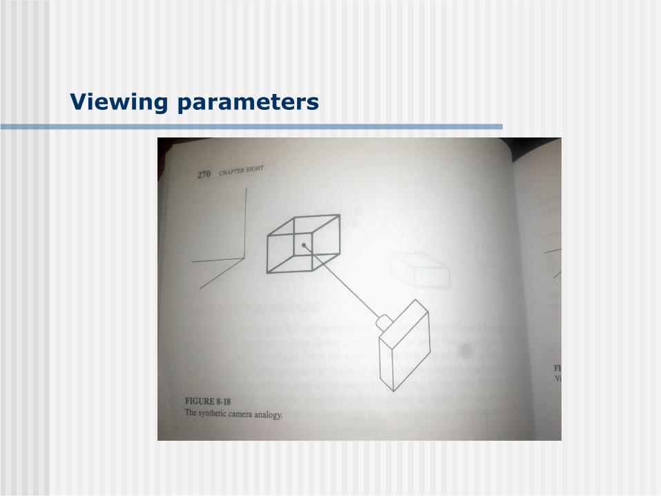
Conceptual Model of the 3D viewing process
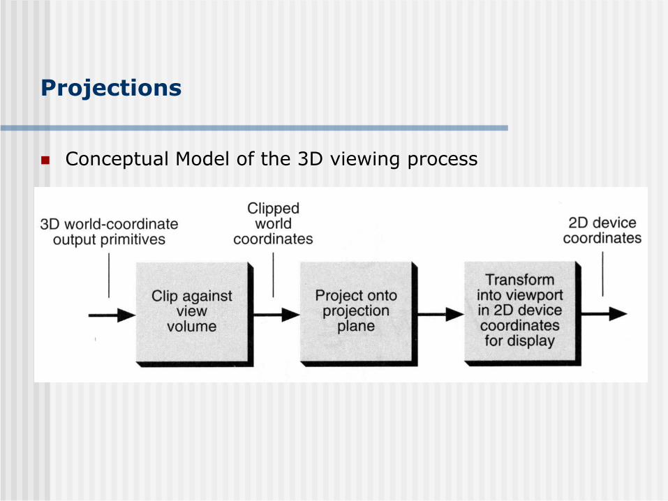
3D Projections
Perspective Parallel
Orthographic Oblique
Elevations Axonometric
Isometric
Cavalier Cabinet
(Rays parallel to view plane) (Rays converge on eye position)
Parallel projection
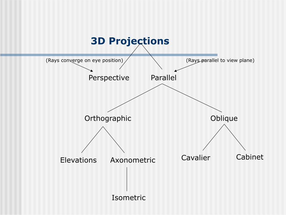
Parallel projection
All projection lines are parallel to each other ;
preserve relative proportions
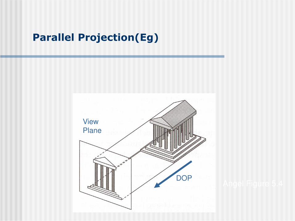
Parallel Projection(Eg)
Angel Figure 5.4
DOP
View
Plane
Parallel Projections
2 principle types:
orthographic and oblique.
Orthographic :
direction of projection = normal (means perpendicular) to the projection plane.
Oblique :
direction of projection != normal to the projection plane. (means not perpendicular)
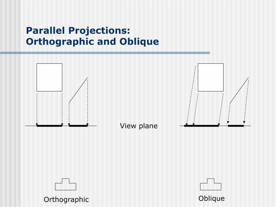
Parallel Projections: Orthographic and Oblique
View plane
Orthographic Oblique
Parallel Projections
Orthographic (or orthogonal) projections:
front elevation, top-elevation and side-elevation.
Useful because angle and distance measurements can be made...
However, As only one face of an object is shown, it can be hard to create a mental image of the object, even when several view are available.

Parallel Projections
Orthogonal projections:
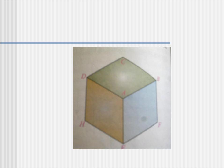
Isometric Projection
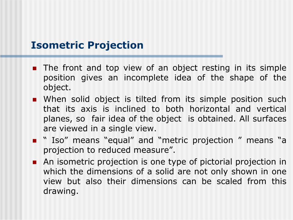
The front and top view of an object resting in its simple position gives an incomplete idea of the shape of the object.
When solid object is tilted from its simple position such that its axis is inclined to both horizontal and vertical planes, so fair idea of the object is obtained. All surfaces are viewed in a single view.
“ Iso” means “equal” and “metric projection ” means “a projection to reduced measure”.
An isometric projection is one type of pictorial projection in which the dimensions of a solid are not only shown in one view but also their dimensions can be scaled from this drawing.
Oblique projections
It is parallel projection.
The isometric projection of any object is pictorial view in distorted shapes with equal shortened dimensions. This means that the square ,rectangle and circular faces are seen as a rhombus, parallelogram and ellipse respectively.
An oblique projection is formed by parallel projections from a center of projection at infinity that intersects the plane of projection at an oblique angle, providing the general 3D shape of the object.
Oblique means slanting.
Oblique projections
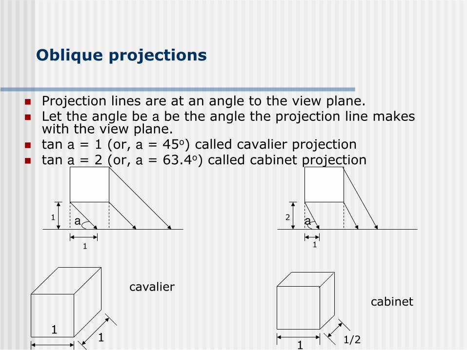
Projection lines are at an angle to the view plane. Let the angle be a be the angle the projection line makes
with the view plane. tan a = 1 (or, a = 45o) called cavalier projection tan a = 2 (or, a = 63.4o) called cabinet projection
cavalier
cabinet
a
1 1
1
1
a
1 1/2
2
1
Some points @
In cavalier projection , the projection of a line perpendicular to the view plane has the same length as the line itself.
In cabinet projection, the projection of a line perpendicular to the view plane has one half length as the line itself.

Perspective projection
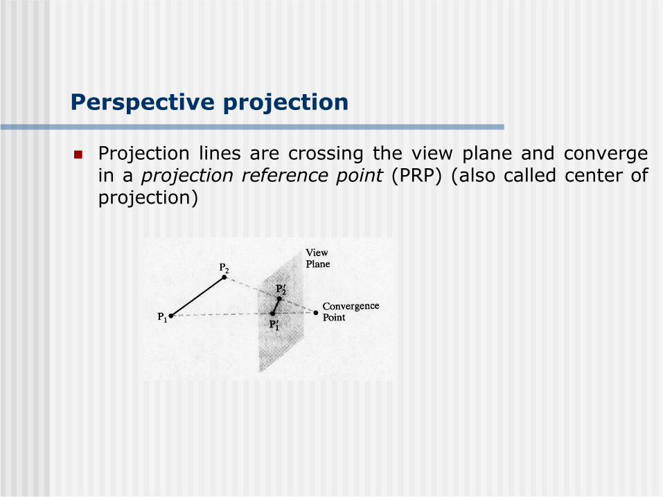
Projection lines are crossing the view plane and converge in a projection reference point (PRP) (also called center of projection)

Perspective vs. Parallel
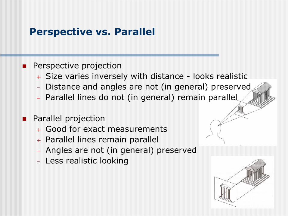
Perspective projection
+ Size varies inversely with distance - looks realistic
– Distance and angles are not (in general) preserved
– Parallel lines do not (in general) remain parallel
Parallel projection
+ Good for exact measurements
+ Parallel lines remain parallel
– Angles are not (in general) preserved
– Less realistic looking
Again perspective projection
Vanishing Point : the perspective projection of any set of parallel lines that are not parallel to the projection plane converge to a vanishing point.
Category of perspective projection
1. 1 point perspective projection
2. 2 point perspective projection
3. 3 point perspective projection
Viewing parameters
Viewing parameters
We can view the object from the top, or the side or from the behind. Therefore , it is necessary to choose a particular view for a picture by defining view plane.
View plane : it is film in the camera ..on which we want to take photograph.
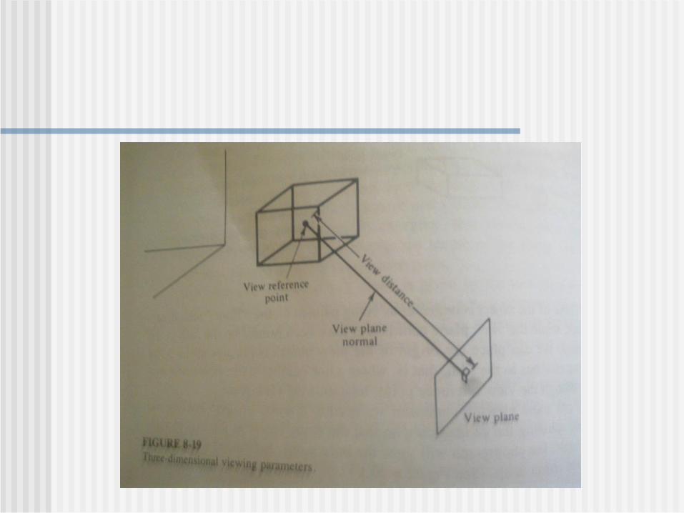
View reference point: this point is the center of our viewing coordinate system.
View plane normal vector: this normal vector is the direction perpendicular to the view plane.
View distance: distance between the view plane and the view reference point.
It is possible to obtain the different views by rotating the camera about the view plane normal vector and keeping view reference point and direction of N vector fixed.
view-up vector V :Rotation of camera or view plane is specified by view-up vector V
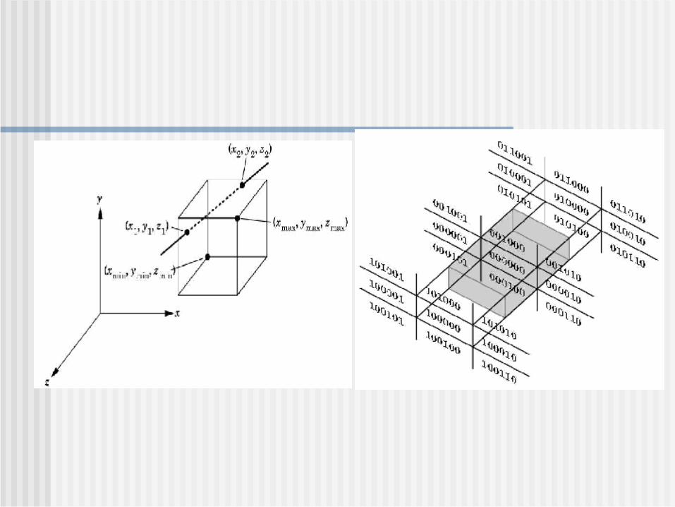
3D Clipping ( clipping against volume) Cube
• Both the Cohen-Sutherland and Cyrus-Beck clipping algorithm readily extend to 3D.
• For Cohen-Sutherland algorithm use two extra-bit in outcode for incorporating z < zmin and z > zmax regions
• We have to use 6bit outcode instead of 4-bit.
• Bit1 =1 if end point is to the left of the volume.
• Bit2 =1 if end point is to the right of the volume.
• Bit3 =1 if end point is to the bellow of the volume.
• Bit4 =1 if end point is to the above of the volume.
• Bit5 =1 if end point is to the front of the volume.
• Bit6 =1 if end point is to the back of the volume.
• Otherwise bit is set to zero.