Embed Size (px)
Citation preview

Progress on Levitation in the
Levitated Dipole Experiment
D.T. Garnier, M.E. Mauel, T. Sunn Pedersen – Columbia University
A. Boxer, J. Ellsworth, I. Karim, J. Kesner, P. Michael, E. Ortiz, A. Radovinsky, – MIT PSFC
2006 Innovative Confinement Concepts WorkshopAustin, Texas
February 13-16, 2006
Columbia University
Synopsis
Levitation will likely greatly change operation of LDX‣Dominant loss channel removed -> better confinement
‣Higher background density with high beta -> more stable to HEI
‣Radial transport dominated (broader) profile -> more stable
Levitation system nearly complete‣Coil and control systems installation complete
‣Calibration and control algorithm development underway
‣ Laser detection system prototype complete
‣Catcher system under construction
Levitation system testing in progress‣ 3 major tests planned to give confidence in successful levitation

Bulk plasma must satisfy MHD adiabaticity condition
Fast electron stability enhanced due to coupling of fast electrons to background ions
Hot Electron Interchange Stability
Krall (1966), Berk (1976)...
Rosenbluth and Longmire, (1957)
!!
pb V ""
= 0
!
d ln pb
d ln V< !!1
V =!
d !
Bwhere
or
!d ln n̄ h
d ln V< 1+
m 2
"
24
!d h
!c i
n̄ i
n̄ h
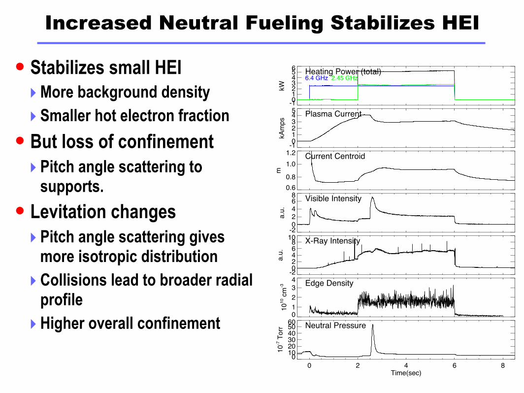
Increased Neutral Fueling Stabilizes HEI
Stabilizes small HEI‣More background density
‣Smaller hot electron fraction
But loss of confinement‣Pitch angle scattering to
supports.
Levitation changes‣Pitch angle scattering gives
more isotropic distribution
‣Collisions lead to broader radial profile
‣Higher overall confinement
-10123456
kW
Heating Power (total)6.4 GHz 2.45 GHz
-1012345
kA
mp
s
Plasma Current
0.6
0.8
1.0
1.2
m
Current Centroid
-202468
a.u
.
Visible Intensity
-202468
10
a.u
.
X-Ray Intensity
01
2
34
10
10 c
m-3 Edge Density
0 2 4 6 8Time(sec)
0102030405060
10
-7 T
orr Neutral Pressure

LDX Levitation Basics
2 m
Levitation by upper lift magnet‣ Unstable only to vertical motion
‣ Mostly undamped stable secondary modes
HTS lift magnet‣ First in US Fusion program
‣ Much reduced power and cooling requirements
‣ AC heating introduces unique requirements for control system
Large 5 m diameter vacuum vessel‣ Eddy current times << levitation times
Laser position detection‣ Many secondary diagnostics
Digital feedback system
L-coil
F-coil
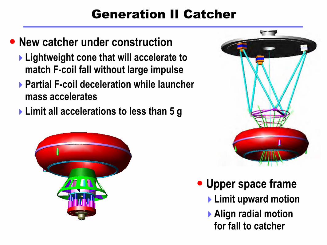
Generation II Catcher
New catcher under construction‣ Lightweight cone that will accelerate to
match F-coil fall without large impulse
‣Partial F-coil deceleration while launcher mass accelerates
‣ Limit all accelerations to less than 5 g
Upper space frame‣ Limit upward motion
‣Align radial motion for fall to catcher

L-Coil Design
High Temperature Superconductor.
‣ Negligibly power consumption compared to resistive equivalent.
‣ Nominal 105 A current, with ± 1 A, 1 Hz position control ripple.
‣ Easier to manage position control ac loss than for LTS.
‣ Funded by SBIR, first HTS coil in US fusion energy program.
Optimized, disk-shape geometry for F-coil levitation.
‣ Double pancake winding.
‣ Center support and cooling plate.
Conduction cooled coil.
‣ Low maintenance, moderate cost,
high conductor performance.
‣ Estimated 12 W hysteresis loss.
‣ One-stage cryocooler for coil. 20W @ 20K
‣ Liquid nitrogen reservoir
for radiation shield.

Levitation Control System

LDX Control System Description
150A, +/- 100V Power Supply‣ Integrated dump resistor for rapid discharge
Realtime digital control computer‣ Matlab/Simulink Opal-RT development environment
‣ 5 kHz feedback loop
Failsafe backup for upper fault
Programmable Logic Controller‣ Slow fault conditions
‣ Vacuum & Cryogenic monitoring
‣ PS user interface
Optical link to control room
User interface
LDX data system

Levitation Control System Schematic
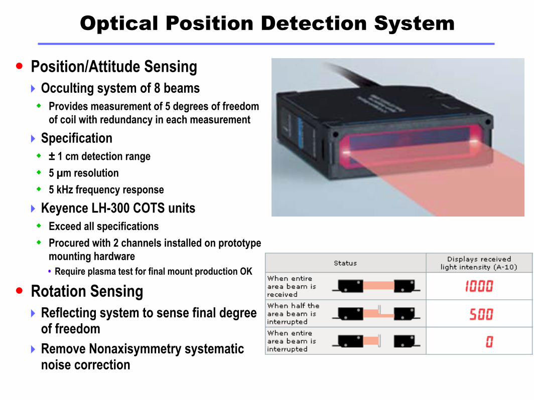
Optical Position Detection System
Position/Attitude Sensing‣ Occulting system of 8 beams Provides measurement of 5 degrees of freedom
of coil with redundancy in each measurement
‣ Specification ± 1 cm detection range
5 µm resolution
5 kHz frequency response
‣ Keyence LH-300 COTS units Exceed all specifications
Procured with 2 channels installed on prototype mounting hardware• Require plasma test for final mount production OK
Rotation Sensing‣ Reflecting system to sense final degree
of freedom
‣ Remove Nonaxisymmetry systematic noise correction
Levitation Physics
x
y
z
L-coil
F-coil
Fgrav
Fmag
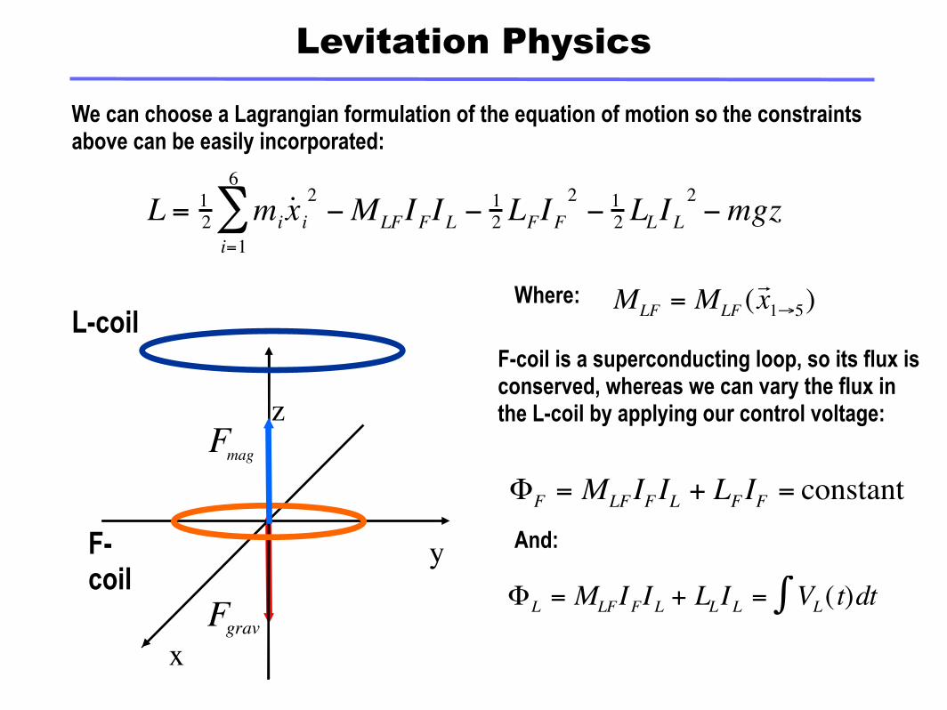
We can choose a Lagrangian formulation of the equation of motion so the constraints above can be easily incorporated:
€
L = 12 mi ˙ x i
2
i=1
6
∑ −MLFIFIL −12 LFIF
2− 1
2 LLIL2−mgz
F-coil is a superconducting loop, so its flux is conserved, whereas we can vary the flux in the L-coil by applying our control voltage:
€
ΦF = MLFIFIL + LFIF = constant
€
ΦL = MLFIFIL + LLIL = VL( t)dt∫
€
MLF = MLF (r x 1→5)Where:
And:

Feedback stabilization
IL (t )= I0 − a0 ε (t)dt − a1ε (t)− a2ε'∫ (t)
Automatic correction to I0 Damping term, acts like friction
The upward force on the F-coil is proportional to the radial magnetic field at
its position, generated by the L-coil.
Hence, it is proportional to the current in the L-coil.
Without feedback, the vertical position is unstable because dBR/dz>0, so if the F-coil moves up, the upward electromagnetic force will increase, and the
coil will move even further up.
If we detect a small increase in vertical position, and decrease the L-coil current appropriately, we can bring the coil back to its original position.
Simple Approach: Use proportional-integral-derivative (PID) feedback:
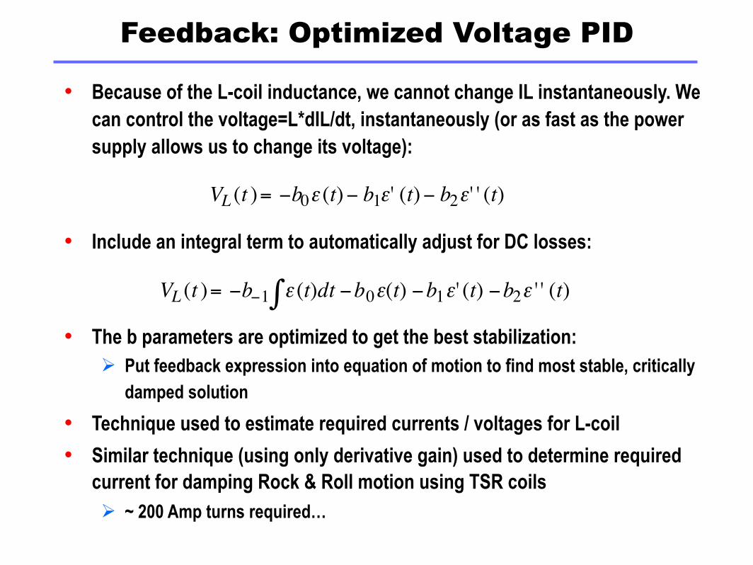
Because of the L-coil inductance, we cannot change IL instantaneously. We can control the voltage=L*dIL/dt, instantaneously (or as fast as the power supply allows us to change its voltage):
Include an integral term to automatically adjust for DC losses:
The b parameters are optimized to get the best stabilization: Put feedback expression into equation of motion to find most stable, critically
damped solution
Technique used to estimate required currents / voltages for L-coil
Similar technique (using only derivative gain) used to determine required current for damping Rock & Roll motion using TSR coils ~ 200 Amp turns required…
Feedback: Optimized Voltage PID
VL (t )= −b0ε (t)− b1ε' (t)− b2ε' ' (t)
VL (t )= −b−1 ε (t)dt∫ −b0ε(t) −b1ε' (t) −b2ε ' ' (t)

Basic Simulink Levitation Model
This basic model simulates 6 degrees of freedom of F-coil with L-coil levitation using voltage feedback control.
1s
velocity
1s
position
MATLABFunction
gravity
VectorSelector
Selector3
VectorSelector
Selector1
VectorSelector
Selector
Scope
Product
PID
PID Controller
f(u)
Mlf(u)
MATLABFunction
Mlf'(u)
-C-
Mass vector
Mlf
Mlf'
Ll
Lf
FluxL
FluxF
Magnetic Forces
Magnetic Force
2
Ll
.6
Lf
1s
L-coil flux
.6*2070
F-coil Flux
du/dt
Derivative
em66
Accel
6
6
6
6
6
66
6
6
66
6
6
6
6
6
6
V
A
3
ZX
AX

Levitation Physics - Simulink Model
… solving for the magnetic force on the F-coil due to the L-coil in terms of the flux gives:
This equation translated to a Simulink model might look like:
€
Fmagnetic =r ∇ MLF
(MLFΦF − LFΦL )(MLFΦL − LLΦF )(LLLF − MLF
2)2

Basic Levitation Model Results
Control parameters as calculated from analytic optimization for voltage PID loop‣ Simulations stay within L-coil supply
specifications
Simulink works!‣ Results match previous numerical
simulations
‣ Analytic analysis eigenmodes are 1.0 and 0.4 Hz
On to implementation!
0
0.2
0.4
0.6
0.8
1x 10
-3 F-coil Z PositionF-coil Z Position
-1
-0.5
0
0.5
1x 10
-3 F-coil X PostionF-coil X Postion
-2
-1
0
1
2x 10
-3 F-coil Tilt about Y-axisF-coil Tilt about Y-axis
-20
-10
0
10
20
30
40F-coil Vertical AccelerationF-coil Vertical Acceleration
0 1 2 3 4 5 6 7 8 9 10-20
-15
-10
-5
0
5
10L-coil Control VoltageL-coil Control Voltage

LDX Control System State Machine
Design of simple levitation controllers requires linear approximation of dynamics near operational point
But magnetic forces are go like L3
Use a state machine to ensure safe operation of system while not near flight status
‣Simulink Stateflow handles state machine in LDX control design

c_pos
current_level
l_pos
reset
voltage_switch
l_posd
l_speed
eloce
enable
stateflow_block
l_pos
current
F_mag
F_launch
Z
scopes_block
l_speed
l_posdl_pos
launcher_block
Z_velocity
reset
P_gain
I_gain
D_gain
V_demand
feed_back_block
-5000
P_gain
l_pos
L_coil_volt
F_mag
F_launch
Z
Z_velocity
coil_pos
Motion_block
eloce
voltage_switch
Rtn
V-demand
enable
V+
Lcoil_supply_block
V+
Lcoil_volt
current_level
Rtn
Lcoil_block
-5000
I_gain
-200
D_gain
66
66
System Simulink/Stateflow Model
Feedback block
L-coil supply block(Simulated or idealized)
Stateflow model

L-coil Power Supply Simulation
Model of 12 pulse switch regulated power supply for L-coil‣ Uses Simulink Power System Blockset
Internal voltage control feedback loop
1
V+ +- v
Vc
VbVa
A
B
C
pulses
+
-
Universal Bridge1
A
B
C
pulses
+
-
Universal Bridge
+- v
Uc
+- v
Ub
+- v
Ua
acos
TrigonometricFunction1
A
B
C
a2
b2
c2
a3
b3
c3
Three-PhaseTransformer
(Three Windings)
T connector
Saturation4
Saturation
L connector
1s
Integrator
[0]
IC
Ground (input)
.8
Gain7
-K-Gain6
200
Gain4
-K-
Gain3
.0146
Gain2
-K-Gain
butter
AnalogFilter Design
1
alpha_deg
A
B
C
Block
PY
PD
Synchronized12-Pulse Generator
1
3 stop
2
Rtn
1
V demand

State System Simulation
Complete functional model Includes human check wait
statesAutomatic failure modes
tested
Z Position Graph Shows launcher in actionCurrent ramp of L-coil Pre-flight check (Premature) launch Free flight

More Full Simulation Results
Vibrating launcher spring L-coil supply voltage ripple
~ 40 volt ripple
Current ripple is < 50mA
No filtering required
Some state machine bugs…

LCX II: Digitally Controlled Levitation
Levitated Cheerio Experiment II Uses LDX digital control system
LCX I was analog demonstration
Modified PID feedback system Low pass filter added for high
frequency roll-off of derivative gain
Integral reset feature for launch transition
Dynamic model block replaced by I/O and estimators
Real-time graph shows position and control voltage Wiggles indicate non-linearly
stable rolling mode…

Noise reduction necessary
Noise reduction necessary for derivative gains
Multipole filter noise reduction limited due to added phase delay
2 4 6 8 10
-0.04
-0.02
0.02
0.04z!t" with Single!Pole Filters
2 4 6 8 10
103
104
105
I!t"
The DFT power spectrum from a simulation of the l-coil current fluctuations
including the effects from plate eddy currents, the l-coil short, and vacuum
vessel eddy currents. The current fluctuations increased significantly
(from Fig. 1) to ±91 mA.

Kalman Filter Simulation
Kalman filter can be used to reduce noise with minimal latency ‣ Uses a physics based predictor that tracks the real motion and is
updated with every time step
2 4 6 8 10
-0.1
0.1
0.2
0.3
0.4
Actual F!Coil z!t"
2 4 6 8 10
-0.1
0.1
0.2
0.3
0.4
Meas & State F!Coil z
2 4 6 8 10
-15
-10
-5
Volt!t"
2 4 6 8 10
103.2
103.4
103.6
103.8
L!Coil Current
Figure 3. Simulation of F-coil position control using a digital controller and
a Kalman filter. (“Wow!”)

Kalman Filter Reduces L-coil AC Losses
Kalman filter results‣ Improved filter greatly reduces
noise in system
‣Reduced noise leads to reduced AC heating of L-coil
Kalman filter with simple feedback sufficient‣Simulations show this method
should meet our requirements for stable levitation
2 4 6 8 10Hz
0.01
0.02
0.03
0.04
0.05!I"2L!Coil Current Power Spectrum
Figure 4.
The DFT of the l-coil current fluctuations from a simulation of the digital
control of f-coil using a Kalman filter with R = I! 1.
2 4 6 8 10Hz
0.25
0.5
0.75
1
1.25
1.5
1.75
2!I"2L!Coil Current Power Spectrum
Figure 2.
The DFT power spectrum from a simulation of the l-coil current fluctuations
including the effects from plate eddy currents, the l-coil short, and vacuum
vessel eddy currents. The current fluctuations increased significantly
(from Fig. 1) to ±91 mA.
Single Pole Filter
Kalman Filter

Control System Development
Integrated test results‣ System identification to ensure observed behavior
matches system model
‣ Identification of model parameters
Formal check of observability and controllability
Optimal Control Theory‣ MIMO System Simulation
‣ Optimal control with balance of minimization of noise and L-coil heating explicitly
‣ Ensure control system won’t add noise to stable modes
Further state machine testing
Output PointInput Point
In1 Out1
Floating Coil Dynamics
F-coil state measurementcoil voltage output
Feedback System

Levitation Test Program
✓ System integration test‣ Test inter-operation of cryogenic and two control systems
L-coil Integrated Performance Test‣ Test L-coil cryogenic performance under worst-case operation point
Gather data to determine HTS coil quench detection algorithm
‣ Calibrate “transfer function” of L-coil System Check state space model for unknown system variables
Integrated System Plasma Test‣ Characterize noise on levitation diagnostics in plasma environment
‣ Operate L-coil systems at 1/2 current with plasma present Calibrate system using measured lift forces
Levitation Test‣ First levitation with nearby supports and safety lines
Levitated Plasma Operations begin