Embed Size (px)
Citation preview
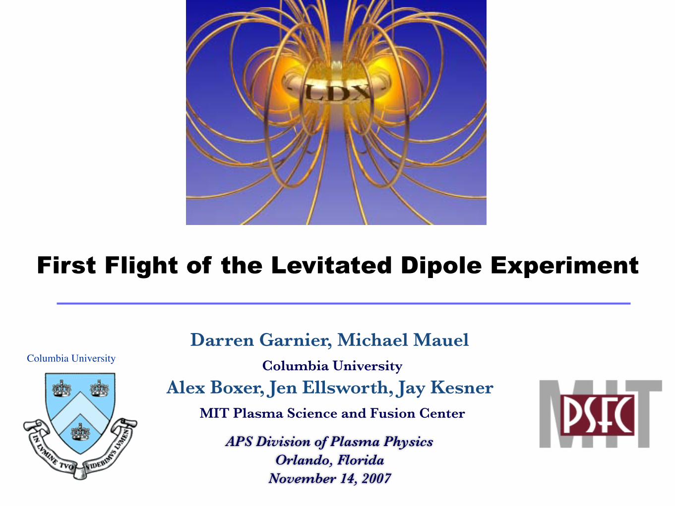
First Flight of the Levitated Dipole Experiment
Darren Garnier, Michael Mauel Columbia University
Alex Boxer, Jen Ellsworth, Jay Kesner MIT Plasma Science and Fusion Center
APS Division of Plasma PhysicsOrlando, Florida
November 14, 2007
Columbia University
Abstract
In the past year, the first levitated experiments have been conducted in the Levitated Dipole Experiment (LDX). LDX, which consists of a 560 kg superconducting coil floating within a 5m diameter vacuum chamber, is designed to study fusion relevant plasmas confined in a dipole magnetic field.
In previous plasma run campaigns, conducted with the dipole coil held by thin supports, stable high beta plasma operations were demonstrated where the plasma kinetic energy is contained in population of energetic particles.
It was expected that levitated experiments would improve confinement by removing the primary loss of energy and particles along field lines. This in turn would lead to higher plasma density and broader radial profiles which should increase the stable operational space.
In February, the first flight of the floating dipole coil was achieved with 40 minutes of continuous levitation and three demonstration plasma shots. This first flight experiment demonstrated the operation of the digital feedback system that provides for stable levitation of the coil.
Further flights were undertaken this fall, leading to the first plasma experiments with the launcher fully removed from the plasma. Initial results confirm many of the expected behaviors.

Levitated Dipole Experiment
1.1 MA Floating dipole coil
‣ Nb3Sn superconductor
‣ Inductively charged by 10 MJ charging coil
‣ Up to 1 hour levitation using active feedback on upper levitation coil
Plasma
‣ Two component plasma created by multi-frequency ECRH
Diagnostics
‣ Magnetics - flux loops, Bp coils, Hall effect sensors
‣ Fast electrons - 4 Channel x-ray PHA, x-ray detector, Hard X-ray camera
‣ Bulk plasma - edge probes, interferometer, visible cameras, visible diode and array
‣ Fluctuations- Edge Isat and Vf probes, Mirnov coils, visible diode array, interferometer
LDX Phase IILevitation
LDX Phase I
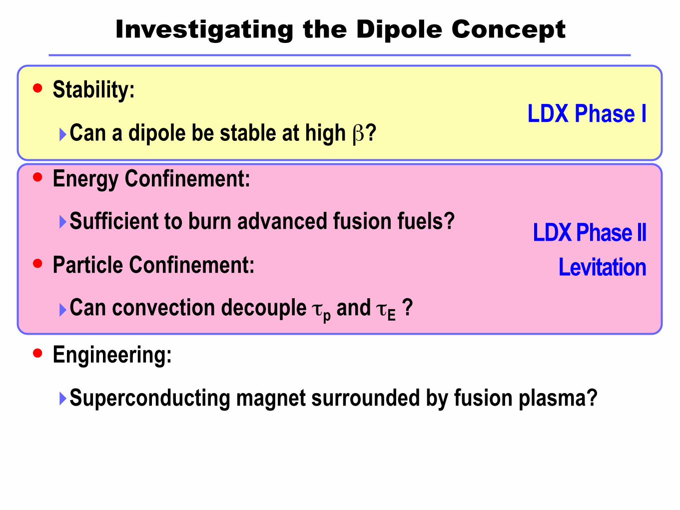
Investigating the Dipole Concept
Stability:
‣Can a dipole be stable at high β?
Energy Confinement:
‣Sufficient to burn advanced fusion fuels?
Particle Confinement:
‣Can convection decouple τp and τE ?
Engineering:
‣Superconducting magnet surrounded by fusion plasma?
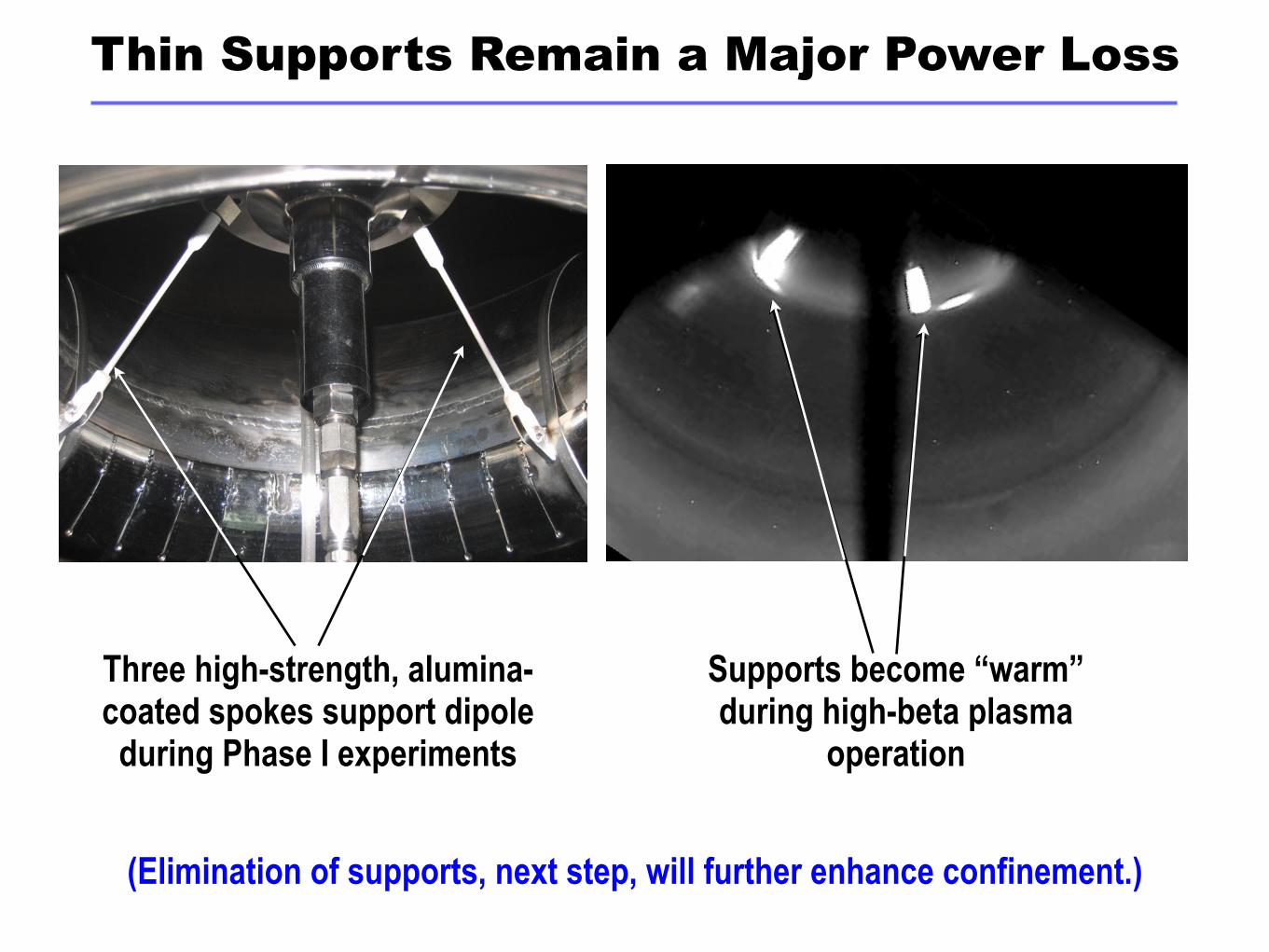
Thin Supports Remain a Major Power Loss
Three high-strength, alumina-coated spokes support dipole during Phase I experiments
Supports become “warm” during high-beta plasma
operation
(Elimination of supports, next step, will further enhance confinement.)
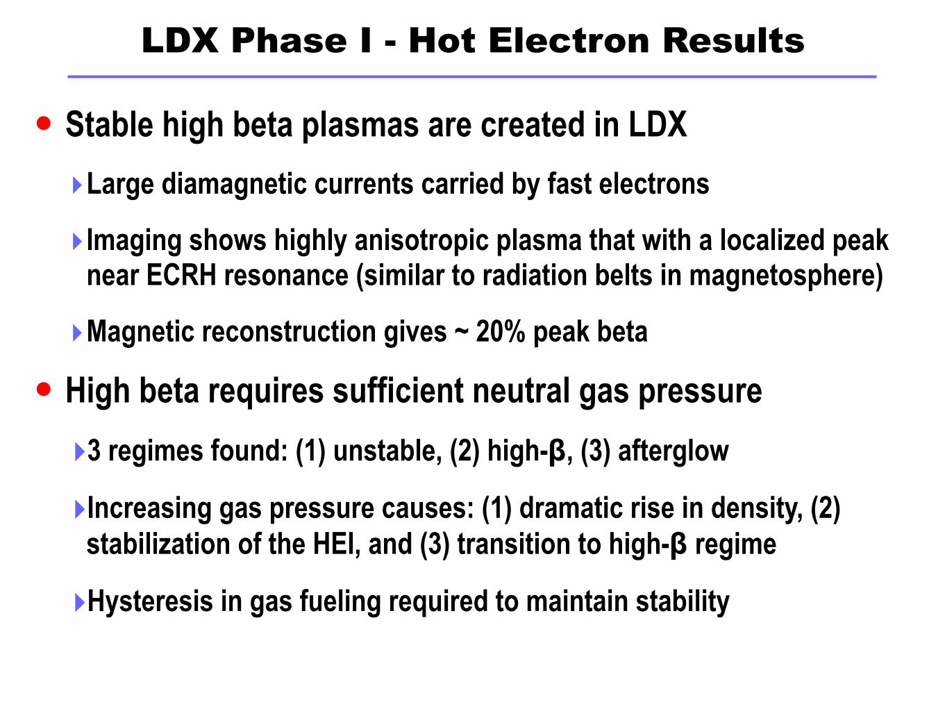
LDX Phase I - Hot Electron Results
Stable high beta plasmas are created in LDX
‣Large diamagnetic currents carried by fast electrons
‣Imaging shows highly anisotropic plasma that with a localized peak near ECRH resonance (similar to radiation belts in magnetosphere)
‣Magnetic reconstruction gives ~ 20% peak beta
High beta requires sufficient neutral gas pressure
‣3 regimes found: (1) unstable, (2) high-β, (3) afterglow
‣Increasing gas pressure causes: (1) dramatic rise in density, (2) stabilization of the HEI, and (3) transition to high-β regime
‣Hysteresis in gas fueling required to maintain stability
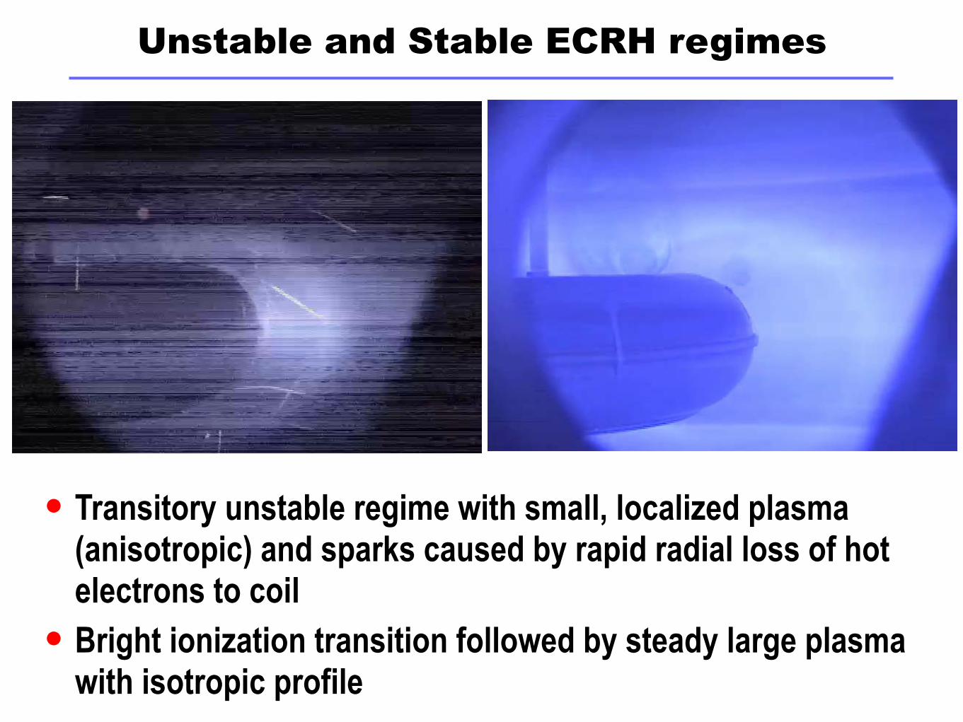
Unstable and Stable ECRH regimes
Transitory unstable regime with small, localized plasma (anisotropic) and sparks caused by rapid radial loss of hot electrons to coil
Bright ionization transition followed by steady large plasma with isotropic profile
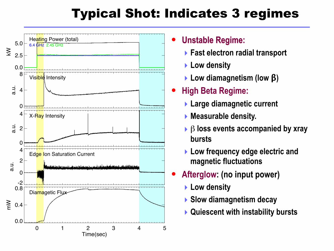
Typical Shot: Indicates 3 regimes
Unstable Regime: ‣ Fast electron radial transport
‣ Low density
‣ Low diamagnetism (low β)
High Beta Regime:
‣ Large diamagnetic current
‣ Measurable density.
‣ β loss events accompanied by xray bursts
‣ Low frequency edge electric and magnetic fluctuations
Afterglow: (no input power)‣ Low density
‣ Slow diamagnetism decay
‣ Quiescent with instability bursts
0.0
2.5
5.0
kW
Heating Power (total)6.4 GHz 2.45 GHz
0
4
8
a.u.
Visible Intensity
0
2
4
a.u.
X-Ray Intensity
-20
2
4
a.u.
Edge Ion Saturation Current
0 1 2 3 4 5Time(sec)
0.0
0.4
0.8
mW
Diamagetic Flux

0.0
2.5
5.0
kW
Total Heating Power
01234
10-6 T
orr Neutral Pressure
0
20
40
a.u.
Visible Intensity
0.0
0.5
1.0a.
u.X-Ray Intensity
0 2 4 6Time(sec)
0.0
0.2
0.4
mW
Diamagetic Flux
Controlling the High-β with Gas Puffing
With sufficient neutral gas pressure, plasma enters high-β regime
With insufficient neutral gas pressure, the plasma will become unstable (sometimes violently)
A hysteresis is the observed thresholds implies the bifurcation of the low density unstable and stable high-β regimes
Qualitatively consistent with theory of the Hot Electron Interchange Mode stability
LDX Phase I - Bulk Plasma Results
Quasi-coherent background instability observed
‣Global scale, bulk density and pressure fluctuations
‣Several candidates for mode
★Entropy mode
★Interchange driven convective cells
★Centrifugal driven mode
Background fluctuations dependent on density profile
‣Frequency of mode dependent on fueling rate/density profile steepness
‣Fluctuation amplitude reduced with flatter density profile
• Ongoing investigation
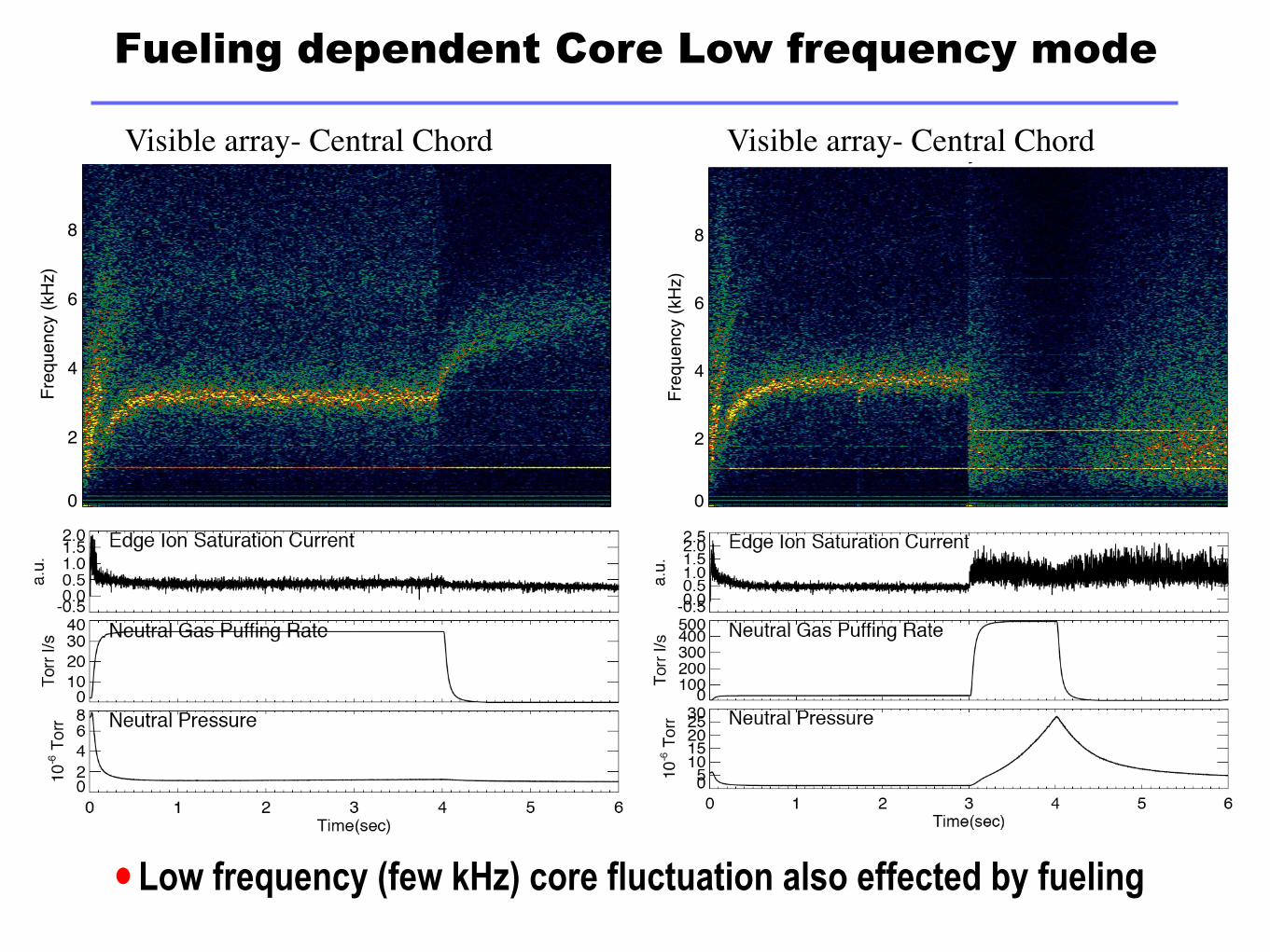
Fueling dependent Core Low frequency mode
1 2 3 4 5Time (sec)
0
2
4
6
8
Freq
uenc
y (k
Hz)
Visible Array, Chord 06
Shot 50513037
1 2 3 4 5Time (sec)
0
2
4
6
8
Freq
uenc
y (k
Hz)
Visible Array, Chord 06
Shot 50513031
Visible array- Central Chord Visible array- Central Chord
• Low frequency (few kHz) core fluctuation also effected by fueling
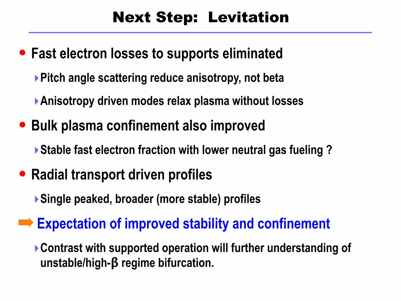
Next Step: Levitation
Fast electron losses to supports eliminated
‣Pitch angle scattering reduce anisotropy, not beta
‣Anisotropy driven modes relax plasma without losses
Bulk plasma confinement also improved
‣Stable fast electron fraction with lower neutral gas fueling ?
Radial transport driven profiles
‣Single peaked, broader (more stable) profiles
➡ Expectation of improved stability and confinement
‣Contrast with supported operation will further understanding of unstable/high-β regime bifurcation.
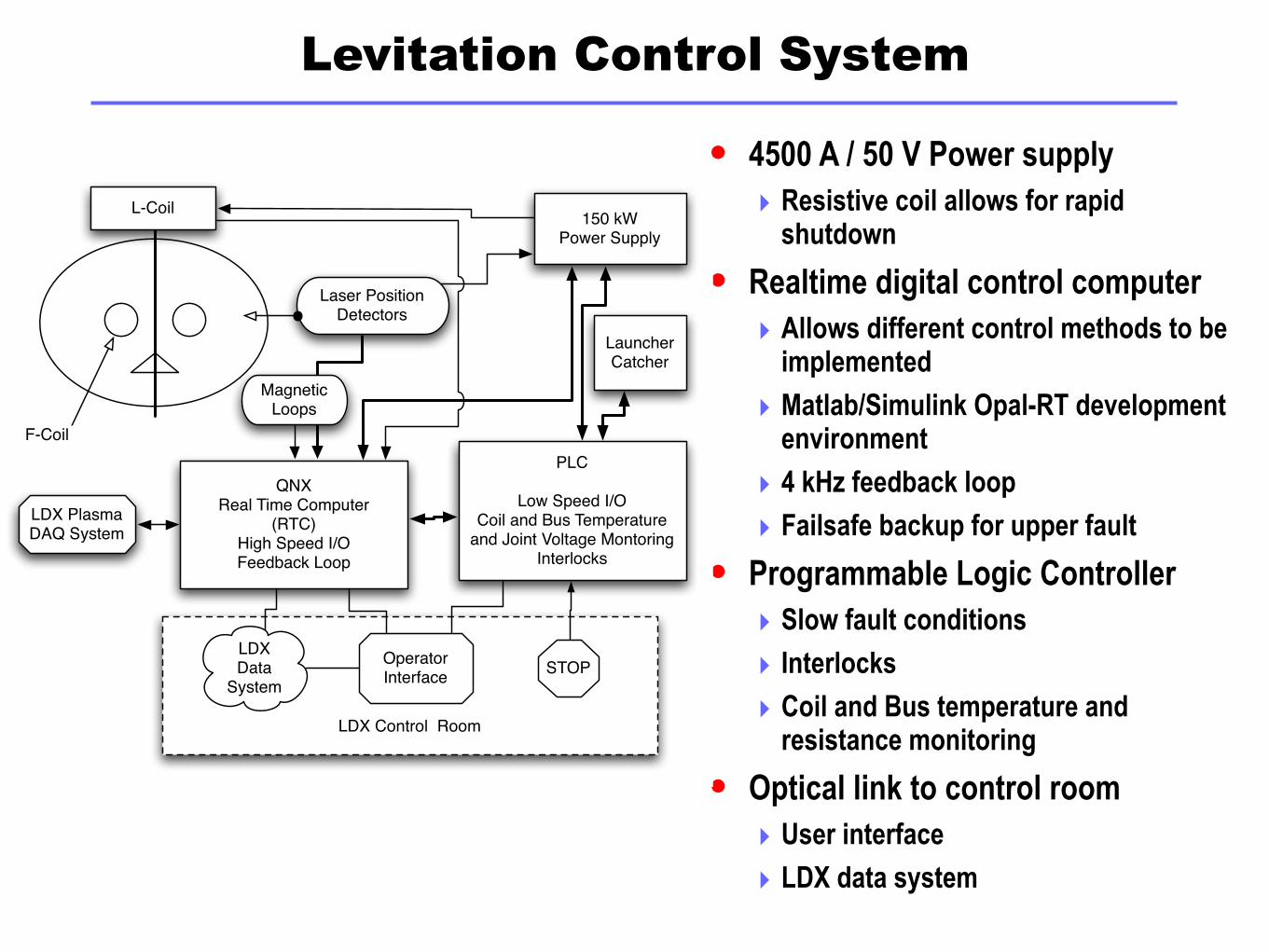
Levitation Control System
4500 A / 50 V Power supply‣ Resistive coil allows for rapid
shutdown
Realtime digital control computer‣ Allows different control methods to be
implemented
‣ Matlab/Simulink Opal-RT development environment
‣ 4 kHz feedback loop
‣ Failsafe backup for upper fault
Programmable Logic Controller‣ Slow fault conditions
‣ Interlocks
‣ Coil and Bus temperature and resistance monitoring
Optical link to control room ‣ User interface
‣ LDX data system
LDX Control Room
Laser Position Detectors
QNXReal Time Computer
(RTC)High Speed I/OFeedback Loop
150 kW Power Supply
Operator Interface
LDX Data
System
PLC
Low Speed I/OCoil and Bus Temperature
and Joint Voltage MontoringInterlocks
STOP
LauncherCatcher
Magnetic Loops
L-Coil
F-Coil
LDX Plasma DAQ System
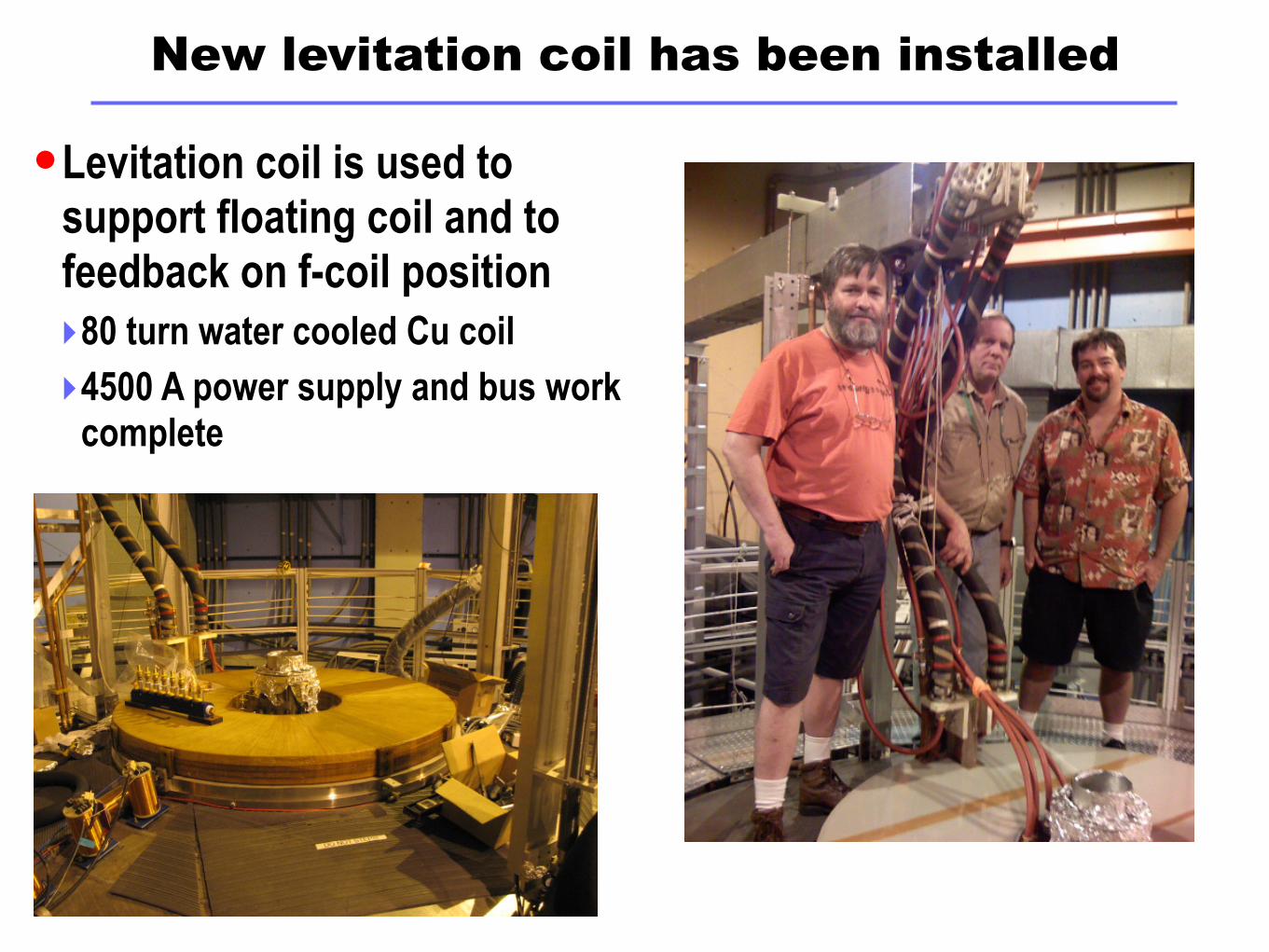
New levitation coil has been installed
Levitation coil is used to support floating coil and to feedback on f-coil position‣80 turn water cooled Cu coil
‣4500 A power supply and bus work complete
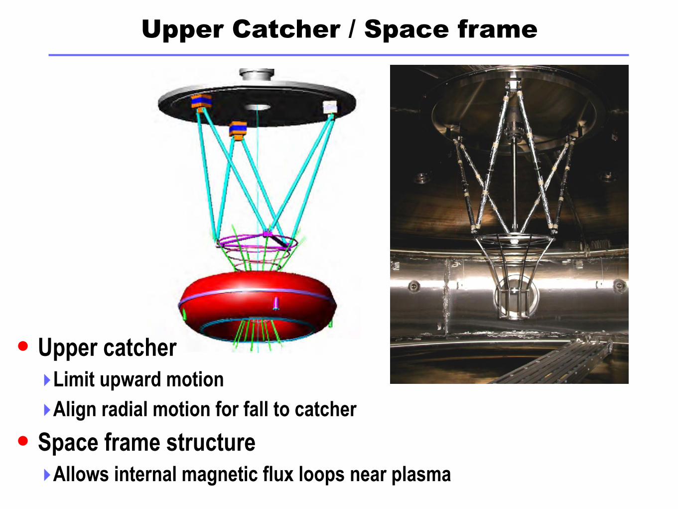
Upper Catcher / Space frame
Upper catcher‣Limit upward motion
‣Align radial motion for fall to catcher
Space frame structure ‣Allows internal magnetic flux loops near plasma
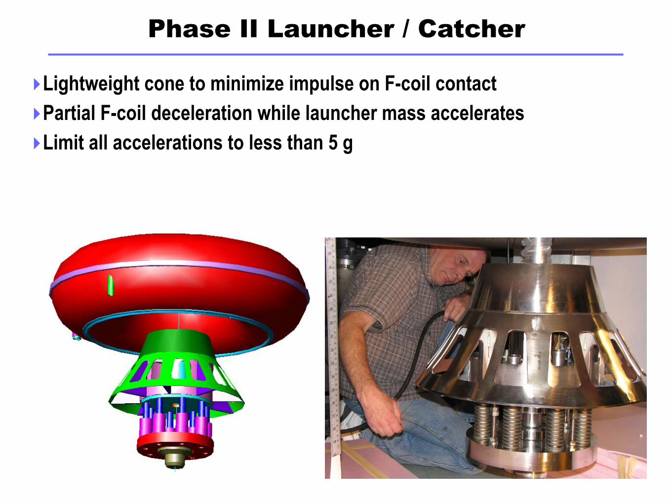
Phase II Launcher / Catcher
‣Lightweight cone to minimize impulse on F-coil contact
‣Partial F-coil deceleration while launcher mass accelerates
‣Limit all accelerations to less than 5 g
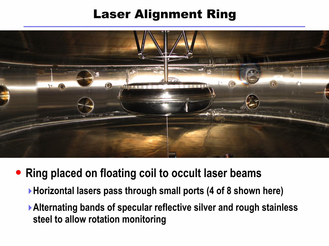
Laser Alignment Ring
Ring placed on floating coil to occult laser beams
‣Horizontal lasers pass through small ports (4 of 8 shown here)
‣Alternating bands of specular reflective silver and rough stainless steel to allow rotation monitoring
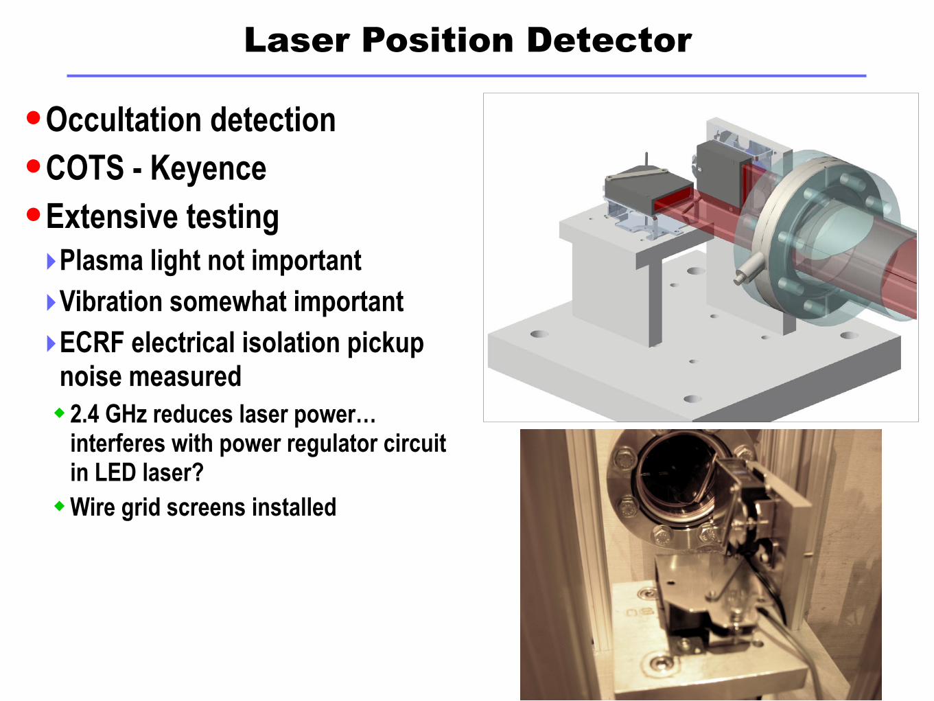
Laser Position Detector
Occultation detection
COTS - Keyence
Extensive testing‣Plasma light not important
‣Vibration somewhat important
‣ECRF electrical isolation pickup noise measured2.4 GHz reduces laser power…
interferes with power regulator circuit in LED laser?
Wire grid screens installed
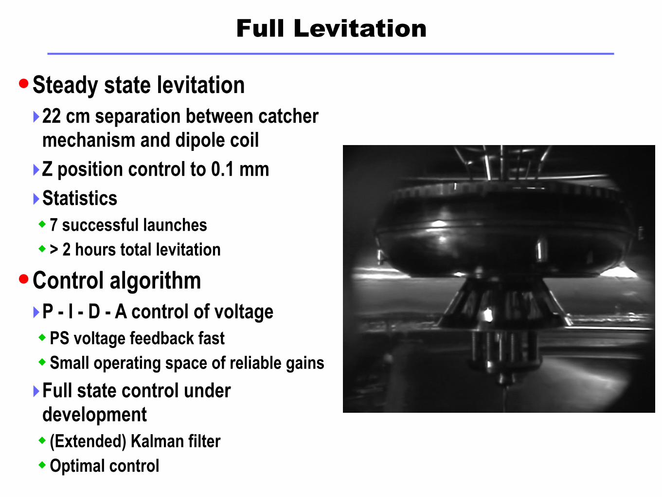
Full Levitation
Steady state levitation‣22 cm separation between catcher
mechanism and dipole coil
‣Z position control to 0.1 mm
‣Statistics7 successful launches> 2 hours total levitation
Control algorithm‣P - I - D - A control of voltagePS voltage feedback fastSmall operating space of reliable gains
‣Full state control under development (Extended) Kalman filterOptimal control
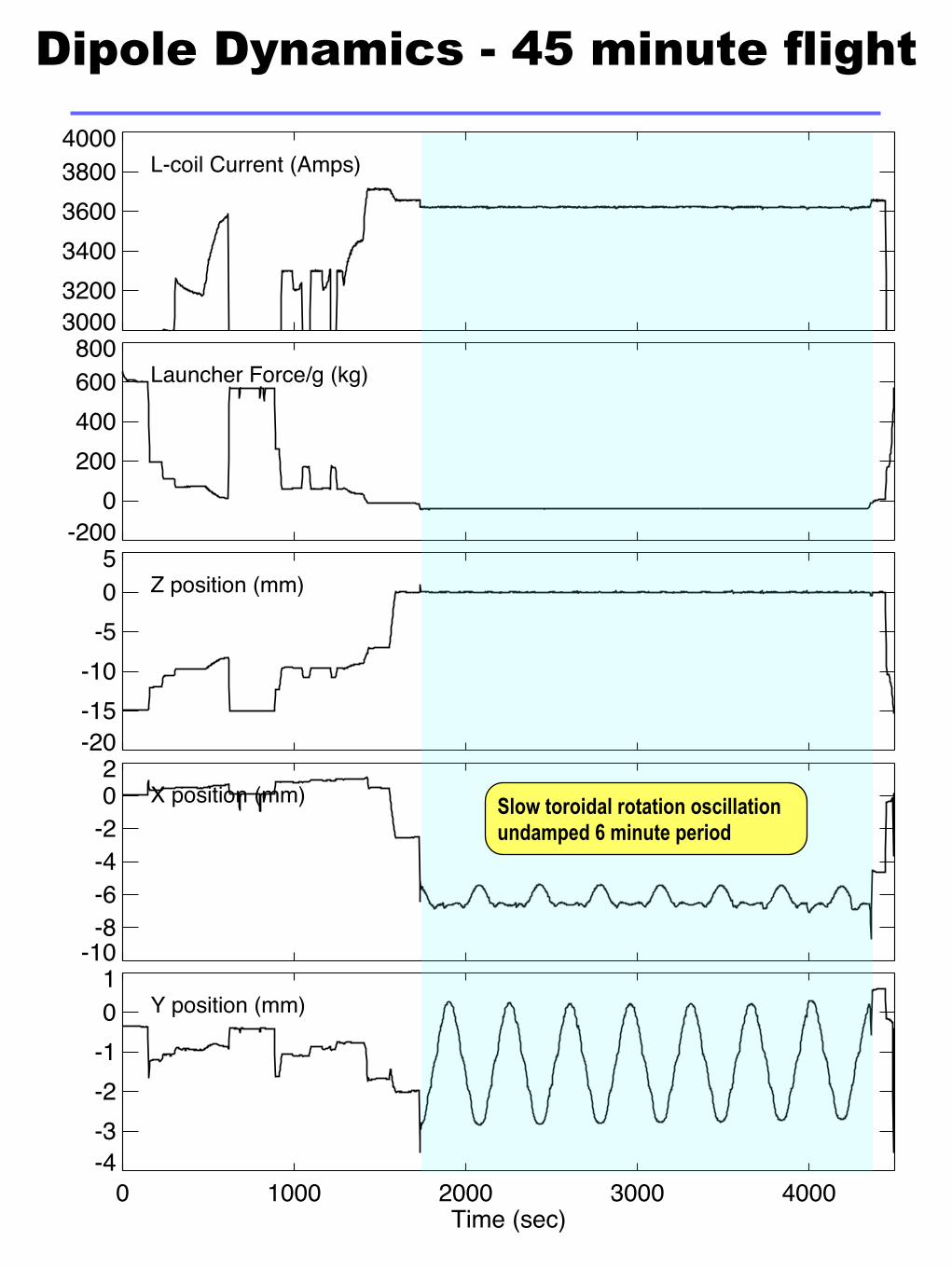
300032003400360038004000
L-coil Current (Amps)
-200
0200400600800
Launcher Force/g (kg)
-20-15-10
-505
Z position (mm)
-10
-8-6-4-202
X position (mm)
0 1000 2000 3000 4000Time (sec)
-4-3-2-101
Y position (mm)
Dipole Dynamics - 45 minute flight
Slow toroidal rotation oscillation undamped 6 minute period
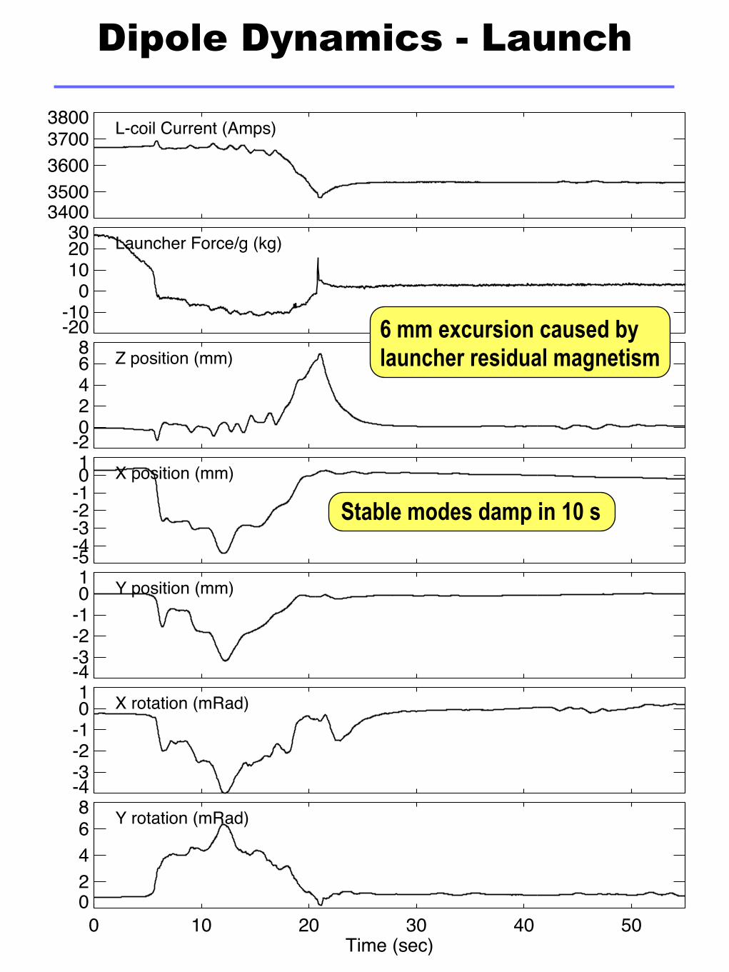
34003500360037003800 L-coil Current (Amps)
-20-10
0102030 Launcher Force/g (kg)
-202468 Z position (mm)
-5-4-3-2-101 X position (mm)
-4-3-2-101 Y position (mm)
-4-3-2-101 X rotation (mRad)
0 10 20 30 40 50Time (sec)
02468 Y rotation (mRad)
Dipole Dynamics - Launch
6 mm excursion caused by launcher residual magnetism
Stable modes damp in 10 s
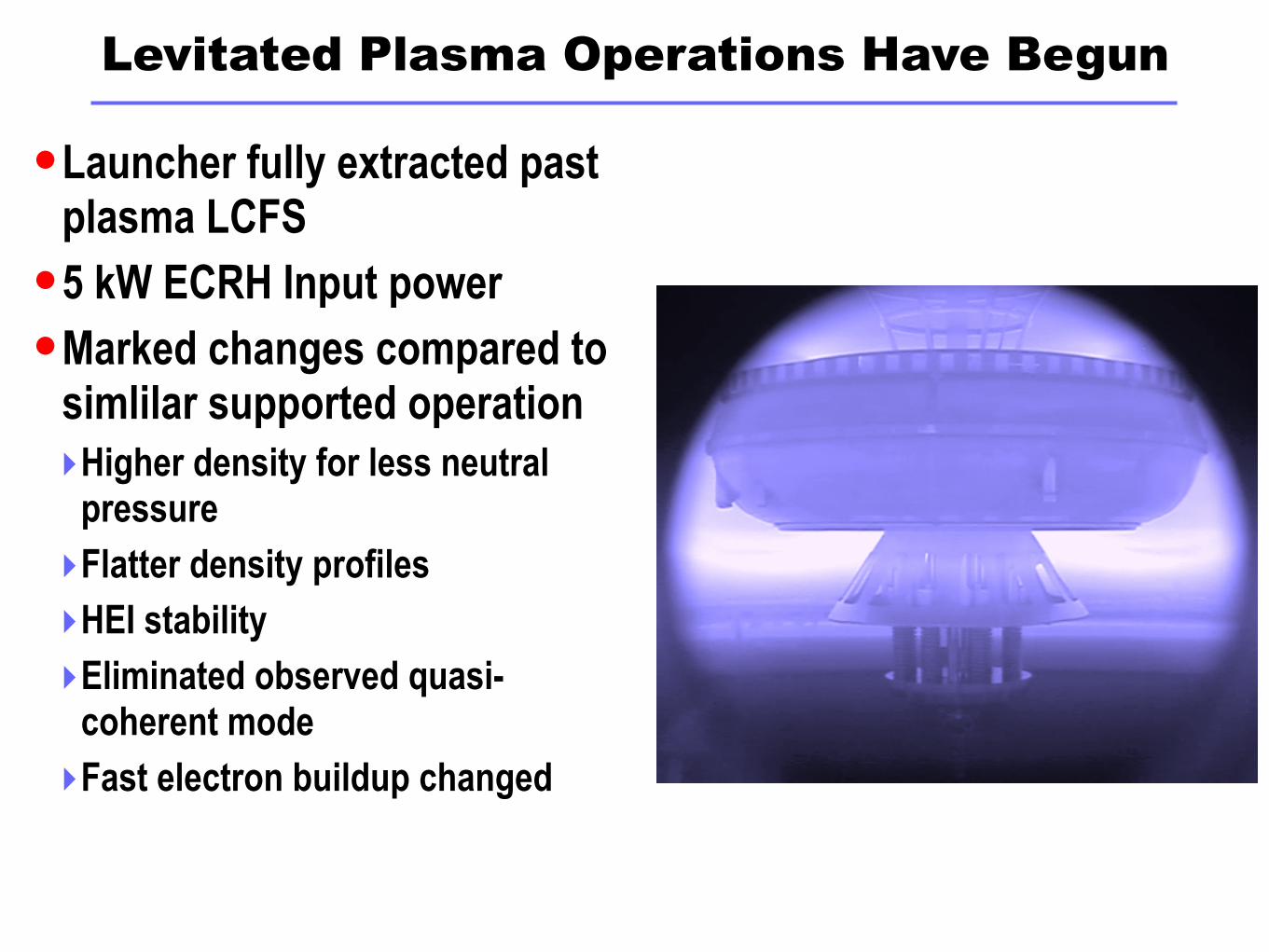
Levitated Plasma Operations Have Begun
Launcher fully extracted past plasma LCFS
5 kW ECRH Input power
Marked changes compared to simlilar supported operation‣Higher density for less neutral
pressure
‣Flatter density profiles
‣HEI stability
‣Eliminated observed quasi-coherent mode
‣Fast electron buildup changed

0.0
2.5
5.0
kW
Total Heating Power
0
1
2
3
4
10-6 T
orr
Neutral Pressure
0
1020304050
a.u.
Visible Intensity
0 2 4 6 8 10Time (sec)
0.00.20.40.60.81.01.21.4
mW
b
Diamagetic Flux
HEI relaxation - Supported
Energy lost to (non-disruptive) HEI relaxation events

0.0
2.5
5.0
kW
Total Heating Power
0
1
2
3
4
10-6 T
orr
Neutral Pressure
-202468
a.u.
Visible Intensity
0 2 4 6 8 10Time (sec)
0.0
0.2
0.4
0.6
mW
b
Diamagetic Flux
No HEI observed when Levitated
Much lower operating neutral pressure allowable
Much different beta buildup(Heating accessiblity?)
02
46
kW
Total Heating Power
0.00.3
0.6
mW
b
Diamagetic Flux
0
20
40
Torr
l/s
Gas fueling rate
02
46
< 10
16 m
-3 > Chord average density
0.00.10.20.30.40.50.6
a.u.
Density Fluctuation Level
0 2 4 6 8 10Time (sec)
0
2
4
6
kHz
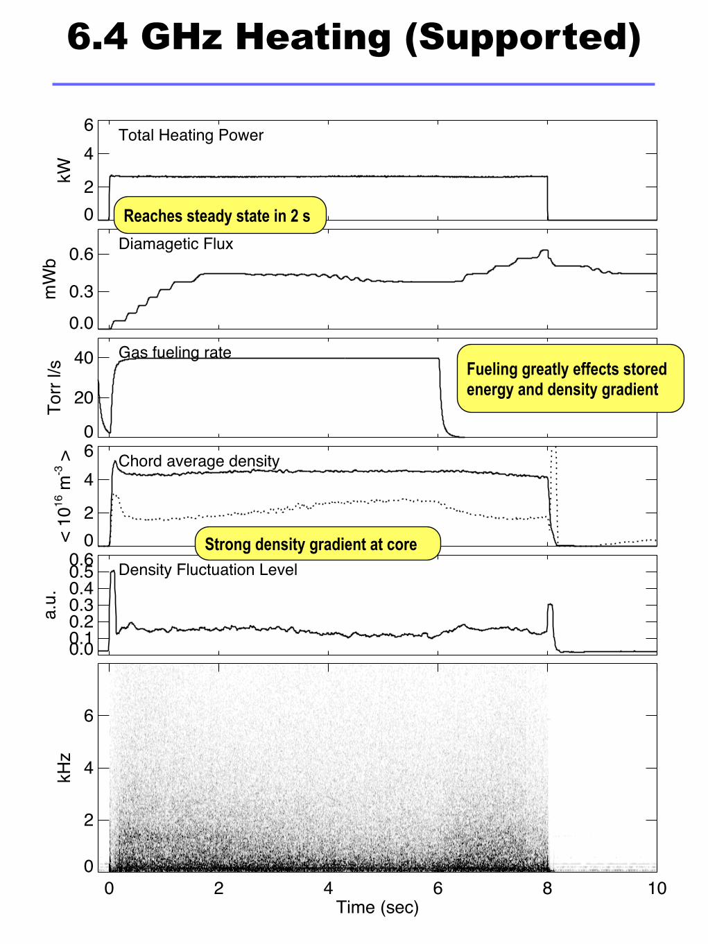
6.4 GHz Heating (Supported)
Strong density gradient at core
Reaches steady state in 2 s
Fueling greatly effects stored energy and density gradient

02
46
kW
Total Heating Power
0.00.3
0.6
mW
b
Diamagetic Flux
0
20
40
Torr
l/s
Gas fueling rate
0246
< 10
16 m
-3 > Chord average density
0.00.20.40.60.81.0
a.u.
Density Fluctuation Level
0 2 4 6 8 10 12 14Time (sec)
0
2
4
6
kHz
6.4 GHz Heating (Levitated)
Flat core density (ECRH cutoff?)
Reaches steady state in ~ 10s
Fueling has minimal effect on density and beta
Broadband density fluctuations unaffected by levitation
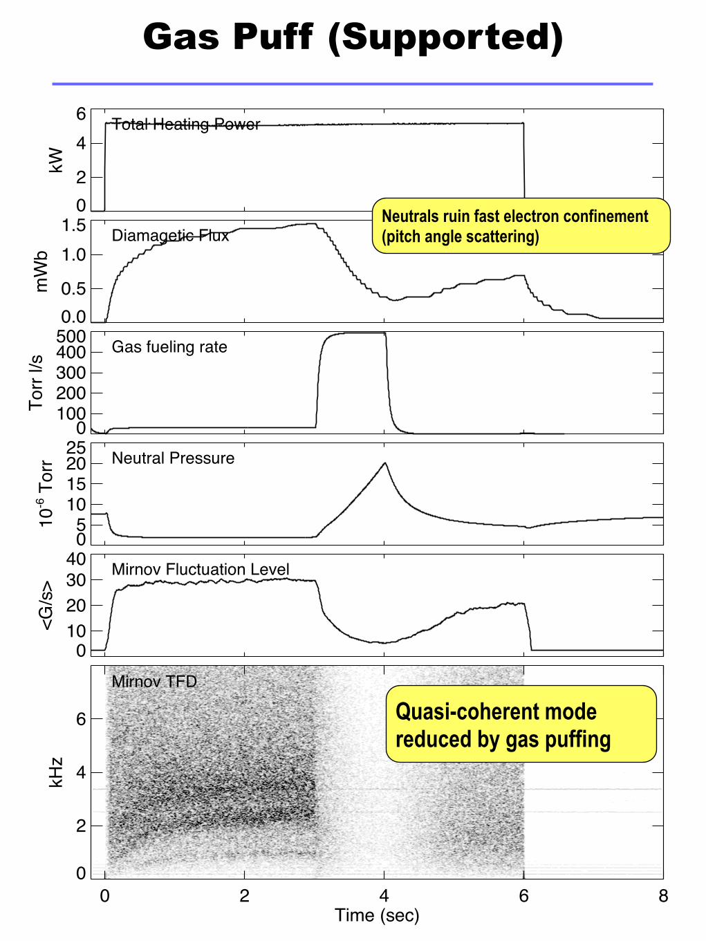
02
46
kW
Total Heating Power
0.00.5
1.01.5
mW
b
Diamagetic Flux
0
100200300400500
Torr
l/s
Gas fueling rate
05
10152025
10-6 T
orr Neutral Pressure
0
10203040
<G/s
>
Mirnov Fluctuation Level
0 2 4 6 8Time (sec)
0
2
4
6
kHz
Mirnov TFD
Gas Puff (Supported)
Quasi-coherent mode reduced by gas puffing
Neutrals ruin fast electron confinement (pitch angle scattering)

02
46
kW
Total Heating Power
0.00.51.01.52.0
mW
b
Diamagetic Flux
0
100
200300
Torr
l/s
Gas fueling rate
02468
10-6 T
orr Neutral Pressure
05
1015202530
<G/s
>
Mirnov Fluctuation Level
0 2 4 6 8 10Time (sec)
0
2
4
6
kHz
Mirnov TFD
Gas Puff (Levitated)
Reduced effect of pitch angle scattering
No evidence of quasi-coherent mode
Synopsis
Full levitation achieved‣Several hours of levitation with new Cu upper levitation coil
‣Levitation control system well developed
‣One run (11/8/2007) with launcher removed past plasma LCFS
Embarking on experimental phase of project‣Levitation allows access to higher density, high beta plasmas
‣Focus on stability, control and confinement of bulk plasma
‣Initial plasma run gives evidence of several expectationsElimination of parallel loss channel for background and fast electronsFlatter radial profilesBetter stability to hot electron interchange mode