Embed Size (px)
Citation preview

Progress in 1m-class, lightweight, CFRP composite mirrors for the ULTRA telescope
Robert C. Romeo∗, Robert N. Martin
Composite Mirror Applications, Inc. , CMA, Tucson, AZ 85710
ABSTRACT Presented are results of continuing optical mirror development program for the NSF ULTRA Telescope. Development of a 16-inch f/4.0 parabolic mirror has been undertaken to adequately define scale-up fabrication procedures for 1m and 1.4m mirrors. 16-inch mirrors have been produced to λ/15 rms (λ=633nm) in the wavefront. These mirrors have been used to produce astronomical images in a Newtonian telescope and yielded quality optical images. Presented will be results of the fabrication of the 1m, f/3 parabolic primary mirror mandrel for the 1m ULTRA Telescope. Also presented will be lab test data and astronomical mages produced under the 16-inch program as well as test data from the replications from the f/3 1m parabola. Keywords: Lightweight mirrors, composite mirrors ULTRA Telescope, replicated optics
1. INTRODUCTION The ULTRA Telescope is a Major Research Instrumentation, MRI, grant funded by the NSF. It is a 3-year program to demonstrate the use of continuous fiber reinforced plastic, CFRP, composite materials for optical telescope mirrors and telescope structures. Bearing in mind that ULTRA is a demonstration program, the primary objective under the MRI is to demonstrate that CFRP mirrors can be used in ground-based optical telescopes, capable of good performance under typical ground-based telescope environments. In the case of ULTRA, the environment is the Mount Laguna Observatory, east of San Diego, CA. Lightweight composite mirrors have not, until recently, been produced to such high accuracy so as to be used in optical imaging applications. Several difficulties arise from the fabrication of CFRP mirrors which, if not carefully considered, can render the mirror useless at wavelengths of 10µm and shorter. Print-through, PT, effects from both fibers and core material will adversely affect the wavefront quality and lower image contrast. This paper will present results of mirror development under the MRI program and the current status of the technology. Optical test results using several test methods will be presented. We present quantitative optical results using a Shack-Hartman wave-front sensor, surface profilometry as well as more classical and qualitative Ronchi testing. Several CFRP mirror designs have been investigated during the course of the ULTRA program with some yielding image quality due to substantial reduction in fiber print-through and complete elimination of core print-through. It must be said, at this point, that although small 150mm mirrors have been produced to diffraction-limited accuracy in the visible band, the effort for ULTRA has been restricted to mirror sizes of 400mm and larger. The emphasis of the ULTRA effort is on producing 1m-class optics and larger for ground-based astronomy. Many of the challenges faced during the ULTRA effort are simply not at issue when producing CFRP mirrors smaller than 400mm. This, however, is not the case for scale-up from 400mm to 1m diameter mirrors. Few assumptions were made during the course of this program as past experience was relied upon for the foundation of the development of CFRP mirrors for ground-based optical telescope applications. Presented here is wave-front data relating to what is referred to as the 3rd generation rigid mirror. CFRP mirrors have evolved under this effort from the 1st generation standard non-core reinforced mirrors, or plate-type mirrors.
∗ [email protected]; Phone 1 520 733-9302 Ext. 106; Fax 1 520 733-9306; compositemirrors.com

2. CFRP MIRROR BASICS For the past 15 years, CMA has been producing mirrors, experimenting with various materials to choose the best materials for meeting such a demanding requirement. Typical mirror requirements are seemingly out of place for the materials and fabrication methods, which have been employed over the years to make mirrors. The nature of CFRP materials is anisotropic, or highly directionally dependant thermal and mechanical properties. This is completely unlike metal, glass or ceramic mirrors, which are all considered isotropic, making them more amenable to classical design configurations and requiring typical fabrication techniques to polish and figure to optical tolerances. We must now look at the basic concepts of CFRP mirrors as they apply to the ULTRA mirror development effort, the material and fabrication methods
2.1. CFRP Materials Carbon fibers are the fundamental material used to produce optical composite mirrors. Carbon fibers come in many different types, with various thermal/mechanical properties such as Young’s Modulus, tensile strength, coefficient of thermal expansion, thermal conductivity, all of which are extremely important when attempting to produce mirrors of high stiffness thermally stable and dimensionally stable. In the raw material form, carbon fibers are delivered as unidirectional, uniformly spread fibers in widths ranging from 6 inches to 52 inches. The material comes in a tape form, on a roll, as carbon fibers pre-impregnated with an uncured, epoxy-type polymer material, known as the matrix. The tape is referred to a prepreg. Fiber and matrix volume fractions are specified by the customer to meet the demands of their particular application. In our case, we specified 65% fiber content by volume. This is typical. The carbon fiber used for the mirrors in this program are Toray M46J, pan-based carbon fibers. The matrix is an elevated cure epoxy-type polymer, the exact formulation of which is proprietary to the supplier. The tape requires heat and pressure to complete the cure cycle. Typical cure temperatures and pressures are 121oC and 1 to 2 atmospheres respectively.
2.1.1. Material Properties As mentioned previously, thermal/mechanical properties are extremely important considerations for optical mirrors. Glass, silicon carbide, beryllium, and aluminum materials, which are typical optical mirror substrates, all must meet minimum standards and requirements in order for them to be eligible candidates for optical mirrors. Essentially, potential mirror substrate materials must exhibit the properties as defined by Yoder1. They must be environmentally stable and machinable or formable to the optical tolerances required of optical telescope mirrors.
2.2. CFRP Mirror Fabrication Technique In generic terms, CFRP mirrors are fabricated via a process called replication or optical surface transfer, OST. In this process, an optical forming mold or mandrel is optically polished to the required optical prescription of the mirror, only in the negative curve, i.e. a convex mandrel is required if a concave CFRP mirror is desired. CFRP prepreg material is then laid-up over a mandrel in a quasi-isotropic orientation, in order to yield a mirror which has uniform in-plane mechanical properties. The material is then cured on the mandrel under vacuum pressure at a temperature of 121oC. The rest of the mirror structure such as core reinforcing material is then attached to the back of the mirror face sheet. After cure, the entire mirror is released from the glass mandrel and ready for optical coating. There is no requirement after the mirror replication for additional polishing or figuring. Fabrication sequence is shown in figure 1. Figure 1 . CFRP fabrication sequence from left to right, processing the glass mandrel, CFRP prepreg material, lay-up
of prepreg over the glass mandrel, processing and release CFRP mirror from the mandrel, ready for coating.

2.3. The Mandrel As previously mentioned, the mandrels used in OST are typically glass and for the purposes of the ULTRA optics development, three mandrels were used. 1. 150mm diameter convex spherical mandrel, 1.9m radius of curvature, ROC, Material: Zerodur 2. 408mm diameter convex parabolic mandrel, 1,6m ROC, material: ZKN7 material 3. 1m diameter convex parabolic mandrel, 6m ROC, Material: cast Pyrex The 150mm mandrel was produced by Pegasus Optics and has a surface accuracy of λ/8 p-v at λ = 633nm. The mandrel is useful for producing CFRP mirrors for surface smoothening techniques. For ULTRA the 150 mm mandrel was a cost effective way of developing optical performance improvements, an example being surface roughness as it is not surface area dependant. The 408mm mandrel was produced by Robert F. Royce at Royce Optical in the most widely used mandrel under this program. Due to its optical characteristics, it was ideal for producing image quality optics. The 1m mandrel, which was cast by Hextek Corporation, Tucson, AZ, is a 5 inch thick plano-convex parabola. It is used to produce the 1m parabolic primary mirror for the ULTRA telescope. The 40 cm and 100 cm mandrels are shown below in figure 2..
Figure 2. LEFT Convex 40cm, parabolic, f/4 ZKN-7 mandrel and RIGHT Convex 1-meter, parabolic, Pyrex mandrel,
both used for ULTRA. Both Produced by R.F. Royce of Royce Optical.
2.4. Optical Testing Methods Optical testing has been performed throughout this program at CMA. Several test methods were employed to determine quantitatively any aberration which may occur on the surface of the CFRP mirrors. The tests methods were designed to quantify aberrations over a large range of size scales. For small scale surface roughness, we used a Wyko Topo 3-D optical surface profiler. Extensive surface roughness measurements have been made on CFRP mirrors and values of between 0.6 nm and 1.5 nm rms on CFRP mirrors replicated from precision glass mandrels intended for visible optics. Because such an extensive amount of data has already been gathered for micro roughness, it was not emphasized for this effort.
2.4.1. Shack-Hartman Wavefront Sensor, WFS For quantifying the wave front quality of the CFRP mirrors, we used a HASO-32 Shack-Hartman wave front sensor. The instrument has a large dynamic range and is relatively insensitive to atmospheric disturbances. The number 32 corresponds to the 32 X 32 micro-lenslet array used as the Shack-Hartman array. The HASO 32 WFS can quantify the wave front in rms and p-v terms, yield Zernike terms out to 64 terms and provide point spread function, PSF information. It is particularly important to be able to measure the spherical aberration term; to know the magnitude of the deviation of a parabola from its best fitting sphere. Further explanation can be found in Malacara2 Of course, the 1st –8th Zernike terms are of most importance when analyzing CFRP mirrors for replication accuracy compared to the mandrel over which it was replicated. The HASO 32 will be used to determine the magnitude of the spherical aberration term for establishing the spherical correction for the CFRP mirror. By establishing the true values of the first 32 Zernike terms, one can discover the influence of such aberrations as core print-through, which can be seen in the higher order terms like trefoil or pentafoil-type aberrations, depending on the actual internal structure of the mirror. For instance, producing a mirror with a [0o/90o] egg-crate core structure, may, if adequate steps are not taken to minimize the effects, result in increased 4th or 5th term values. Whereas a mirror produced with a [0o/60o/-60o] iso-grid may exhibit a trefoil-type Zernike term, which can be measured precisely with the HASO 32. More details on the results of various aberrations on the PSF can be found in Mahajan3 The HASO 32 can clearly define the PSF of the CFRP mirrors, showing the affects of various mirror structure configuration on the FWHM quality of the mirror.
2.4.2. Ronchi Tests A variation on the Foucault or “knife Edge” test, Ronchi is the standard used by amateur telescope makers to test the optical quality of their mirrors. But professional optical shop practitioners also employ Ronchi as a tool to determine figure accuracy and surface roughness. Interferometric testing or wave front testing is usually employed if quantifiable data on the wave front or surface quality of a mirror is required. Although Ronchi is mostly used as a qualitative test for determining the figure of optical mirrors, there is enormous value in using the test to examine the CFRP mirror surface for medium and high spatial frequency structure on the surface such as core and fiber print-through. Three grating sizes were employed in the tester; 50, 100 and 200 lines per inch. The 50 line grating is most useful for visually detecting fiber print-through and the higher line density gratings are helpful for understanding the size of the structure. At 200 lines per inch grating, fiber effects will manifest themselves in the quality of the fringes, while inside or outside the marginal focus of the system. Fringes on a mirror with fiber print-through will appear to be fuzzy or wavy. Generally, a mirror with smooth fringes at 200 lines per inch will be smooth enough for optical astronomical telescope mirrors. Mirror wave front shape can be defined by the Ronchi patterns obtained while either inside or outside the marginal focus of a mirror as defined in Malacara2. Ronchi test forms the basis for qualifying a CFRP mirror and interpretation of Ronchi fringes for the criteria to subjecting the mirror to a more critical and quantifiable test such as the HASO 32.
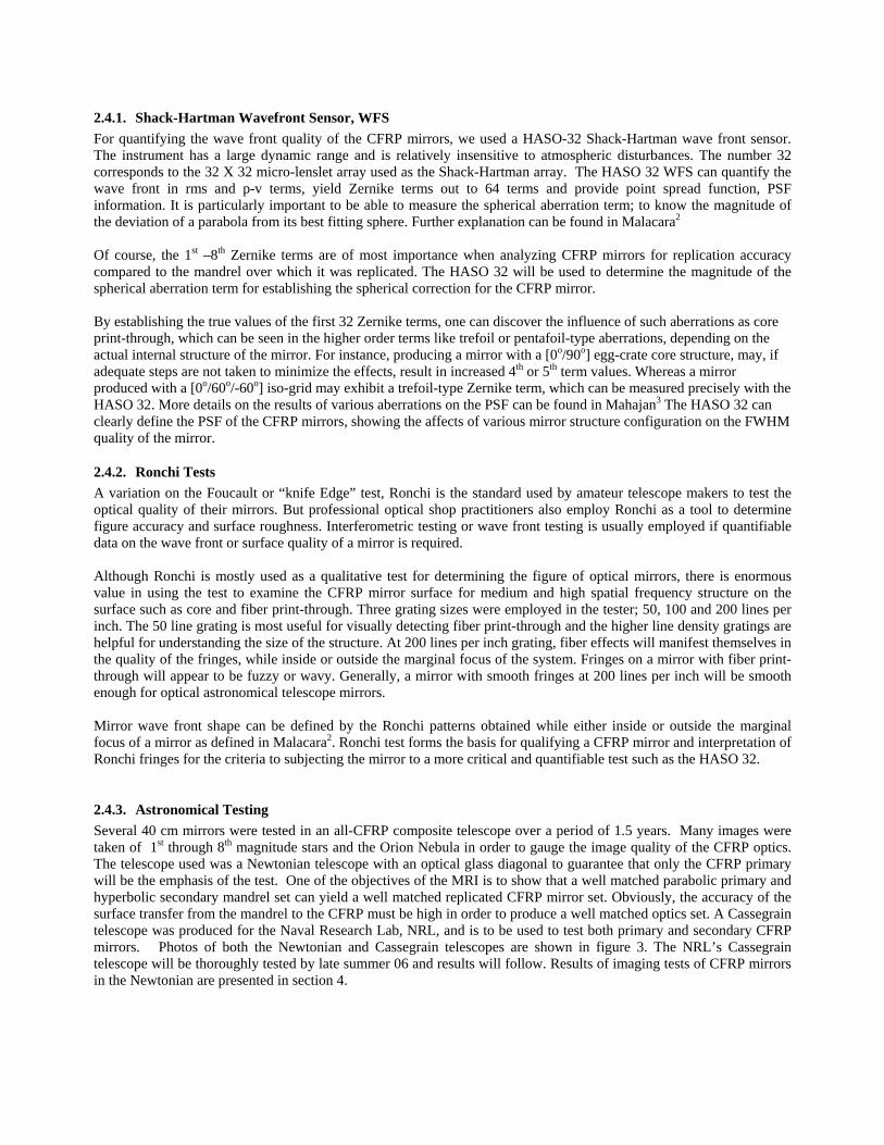
2.4.3. Astronomical Testing Several 40 cm mirrors were tested in an all-CFRP composite telescope over a period of 1.5 years. Many images were taken of 1st through 8th magnitude stars and the Orion Nebula in order to gauge the image quality of the CFRP optics. The telescope used was a Newtonian telescope with an optical glass diagonal to guarantee that only the CFRP primary will be the emphasis of the test. One of the objectives of the MRI is to show that a well matched parabolic primary and hyperbolic secondary mandrel set can yield a well matched replicated CFRP mirror set. Obviously, the accuracy of the surface transfer from the mandrel to the CFRP must be high in order to produce a well matched optics set. A Cassegrain telescope was produced for the Naval Research Lab, NRL, and is to be used to test both primary and secondary CFRP mirrors. Photos of both the Newtonian and Cassegrain telescopes are shown in figure 3. The NRL’s Cassegrain telescope will be thoroughly tested by late summer 06 and results will follow. Results of imaging tests of CFRP mirrors in the Newtonian are presented in section 4.

Figure 3 . LEFT, NRL’s Cassegrain 40cm, All-CFRP composite telescope, weighs 10 kg complete with optics, RIGHT Newtonian 40cm all-CFRP composite telescope for astronomical image testing, weighs 8 kg complete with optics.
3. 40CM CFRP MIRRORS Over the past 2 years, CMA has produced over 30 mirrors, employing several material, process, structural configuration variations. Several plate-type mirrors were produced in order to qualify CFRP mirror substrates, this was largely an exercise in fiber and matrix selection and down selection for the ideal mirror substrate material. Because plate mirrors have shown extreme sensitivity across relatively small temperature bands they are not ideally suited for telescope applications without some tunability of the surface to counteract the thermal deformations. However, they are suitable for active/adaptive primary and secondary mirrors, which CMA is currently investigating for other programs. The goal of ULTRA is to demonstrate a rigid, passive CFRP mirror for both primary and secondary mirrors in a Cassegrain telescope. This being the goal, we extensively investigated rigid, core reinforced sandwich structures for the mirror design. Several criteria were used in the study.
1. Fiber stiffness or Young’s modulus, E: It is assumed that this value must be high in order for the mirror substrate to maintain the highly accurate figure of the mirror.
2. Matrix stability, stability should be moisture resistant and thermally stable. 3. Substrate should have low internal stress in order not to warp when removed from the mandrel 4. Mechanical properties must remain constant for extended periods in a given telescope environment. 5. The matrix must exhibit adequate flow characteristics so that the optical surface has no voids at the
surface after removal from the mandrel.
3.1. Mirror Core The core cell reinforcement configurations studied under this effort were narrowed down to 2 types, 1. “egg-crate”, which is an X-Y square grid shape and 2. isogrid, which is an equilateral triangular configuration. Both are easily manufactured but produce different results in terms of low-order, out-of-plane deflections such as astigmatism. The preferred core reinforcement for maintaining figure over various elevation angles is the isogrid core. Several 40cm

mirrors were produced using isogrid core, all of which maintained excellent figure control. Both core configurations are shown in figure 4 below.
Figure 4. LEFT “egg-crate” CFRP 40cm core and RIGHT Isogrid CFRP 40cm core.
3.2. The Complete 40cm Mirror The typical 40cm CFRP mirror has 2 face sheets of carbon fiber laminates and an isogrid core reinforcement for stiffening. Back face sheet and core are attached after the fabrication of the front mirror faceplate is complete. Several mirror configurations were produced, some with central holes for Cassegrain telescope use and others with no central holes for use in a Newtonian telescope configuration. The two CFRP mirror configurations are shown below in figure 5. Figure 5 . LEFT, Newtonian CFRP 40cm parabolic primary mirror with aluminum + SiO overcoating, RIGHT,
A CFRP Cassegrain 40 cm primary mirror with central hole.

4. 40CM OPTICAL TEST RESULTS The following are results from the 40cm mirror optical tests. The 40cm mirror development is the precursor for the 1m ULTRA telescope and optics. Much progress was made on the 40cm mirrors, nearly all of which was directly scalable to 1m. Scaling from 40cm to 1m is challenging for some fabrication issues and straightforward for other issues.
4.1. Technical Scale-Up Challenges Producing smooth optical surfaces at 150mm is process oriented and that process scales directly to any size. Small scale surface roughness on a CFRP mirror, due to fiber print-through for example, occurs to the same magnitude on a 150mm CFRP mirror as it does on 1m CFRP mirrors. Therefore, the process to eliminate fiber print-through is directly scalable from small to large mirrors. The process of minimizing fiber print-through is as easily implemented at 150mm diameter as it is at 1m. Mandrel Preparation of the 1m glass mandrel for surface transfer is more difficult in terms of processing the release system in a uniform fashion. Inspecting large 1m surface area for cleanliness and release uniformity is a challenge. However, special lighting techniques help to visualize the mold released surface and an additional cleaning step of the surface just prior to lay-up, has helped to minimize surface contamination, resulting in a clean optical surface transfer of the CFRP mirror. CFRP Lay-up Laying up the CFRP material on the glass mandrel in a uniform fashion and maintaining the proper angular orientation of the prepreg tape is essential for quasi-isotropic mechanical/thermal behavior of the CFRP mirror. It is important to minimize the error (within 0.5 degrees) in the ply-orientation angle. More on ply misalignment errors can be found in Hinckley4 This has been achieved on the 1m ULTRA prototype mirror by way of an accurately ruled rotary table. The 0.5 degree requirement is easily maintained by performing the lay-up operation on this table. Removal of CFRP Mirror from Mandrel Releasing the mirror from the mandrel presents challenges in terms of initiating separation between the mirror and mandrel. Special care must be taken in order to reduce fracture and chipping risks on the glass due to the release stress. We have taken several precautions to apply a small stress at one edge of the mirror to allow slow propagation of the release front between the CFRP mirror and the mandrel.
4.2. 40cm Test Results 40cm parabolic CFRP mirrors were produced for optical telescope applications for ULTRA. The results of the 40cm testing paved the way for processing optical mirrors at 1m diameter for the final telescope. Again, the primary objective under the MRI is to demonstrate that CFRP mirrors can be used in ground-based optical telescopes, exhibiting fractional wave performance and capable of performing well under typical ground-based telescope environments. The 40cm results indicate that it is entirely feasible to use CFRP mirrors for this application. The following are test results of 40cm mirrors.
4.2.1. Ronchi Tests Figure X shows a Newtonian mirror under Ronchi test (left) and its theoretical, ideal Ronchigram. The left-hand images in figure 6 was taken with a 50 lines per inch gratings on the 40cm f/4 parabolic CFRP mirrors. They indicate clearly show the patterns of a parabolic surface. These Ronchigrams were compared to theoretical Ronchigrams obtained from a program called Ronchi for Windows, V2.0, John D. Upton, Copyright 1999-2000. Figure 7 is a 50 line per inch Ronchigram of the NRL’s 40cm Cassegrain Telescope.

Figure 6 . LEFT Actual Ronchi images of a 40cm CFRP parabolic mirror (K=-1) taken with 50 lines per inch
grating. Note smooth, converging fringe pattern, characteristic of a well figured parabola. RIGHT image shows the theoretical 50 lines per inch Ronchigram generated as the ideal K=-1 parabola. Aside from contrast differences and a slight turn down edge on the CFRP image, the 2 images look similar, indicating a parabolic figure for the CFRP parabola. The edge of the CFRP mirror can be masked for the astronomical testing.
Figure 7 . Image shows a 50 lines per inch Ronchigram of a CFRP Cassegrain mirror, exhibiting the same paraboloidal shape as in the figure above. This mirror was produced for the NRL’s 40cm Adaptive Optics telescope and will be ready for delivery by May 2006.
4.2.2. HASO 32 Wave Front Sensor Testing The HASO 32 was used to test the 40cm mirrors for the ULTRA mirror development. The data shows that the typical wavefront accuracy of a 40cm CFRP composite mirror is on the order of λ/7 to λ/8 rms ( λ/14 to λ/16 surface) accuracy at λ = 633nm. We know that with a Ross nuller, the 8th Zernike term (3rd order spherical aberration) is removed yielding a spherical wavefront. The HASO correlates the 16 waves of spherical aberration expected in the parabolas shown in figures 6 and 7. This verifies the mirror correction yields a conic constant of –1.0, a parabola adequate for an optical telescope mirror. Figure 8 below shows the typical data produced by the HASO 32 for the mirror in figure 7.

Figure 8. TOP LEFT, camera image of the Shack-Hartman array, each dot represents the location of a calculated slope in the wavefront. TOP RIGHT, “Mixed” mode in the analysis which is a circular area of the lower right corner of the mirror. Synthetic fringes indicate a smooth figure. CENTER, The zonal mode of the HASO 32 which accounts for the mirror surface shown and subtracting only tip, tilt and piston terms. BOTTOM, Modal mode of the HASO 32 showing the rms and p-v value for the mirror accounting for terms higher than the 8th Zernike term, 1st through 8th Zernikes were removed because of the aspheric in the mirror and coma from misalignment, as well as some contribution of misalignment to the astigmatism terms.
It must be noted that the HASO WFS is sensitive to central obscurations and the numerical results of the wave front analysis may be misleading. However, the instrument is useful for quantifying the spherical aberration terms leading to accurate measure of the conic constant, a vital step for qualifying the primary mirror of ULTRA.

4.2.3. 40cm Astronomical imaging tests Attempt were made to qualify the 40cm Newtonian mirrors for astronomical observing and photography. The Newtonian telescope shown in figure 3, with the left hand CFRP mirror in figure 5 was mounted onto a Celestron CGE mount and outfitted with an SBIG 2000 XM camera. The capture program was CCDOPS, which was supplied by SBIG. The telescope was set up at the authors residence in north central Tucson Arizona. Several images were taken over a time period from December 2004 to April 2006. Figure 9 and 10 images were taken early April 2006.
Figure 9 . Image of the Orion Nebula, 2 sec exposure with no filter, on April 2006, Orion is low in the S.W. sky, the small points above the stars indicate a bit of misalignment at the low elevation angle required for the exposure, The star spikes are a combination of spider vane diffraction spikes and minor residual surface texture due to the linear fibers in the CFRP mirror.
Figure 10. Image of Polaris, April 2006, 0.05 sec exposure, no filter. The image subtend an angle of roughly 3 to 4 arcseconds. The smaller stars subtend as low as 2 arcseconds. The seeing was not likely to be better than 2 arcseconds, implying that the images were mostly seeing limited or limited by tracking errors relating to the mount.
Further testing is planned throughout the year as improvements in the telescope stability and optical quality are realized. Testing of the Cassegrain telescope will follow in order to establish a two-CFRP mirror system viability.

5. 1m ULTRA Optics The ULTRA 1m optics development has been based on the progress with the 40cm mirrors. A final 1m CFRP mirror design has been completed at CMA for ULTRA and is currently being fabricated. A prototype mirror has been produced to help define the optical characteristics of the 1m glass mandrel as shown in figure 2. The mirror is a simple plate-type mirror with no core reinforcement. The images of the mirror are shown in figure 11.
Figure 11. LEFT, image shows the 1m parabolic mirror in the test stand and RIGHT, 50 lines per in Ronchigrams of the 1m before final figuring of the 1m mandrel. Fringes are smooth despite astigmatism in the mirror from its being supported on the bottom edge without core reinforcement. Mirror weighs 18 kg.
Figure 12 shows the 1m CFRP ULTRA telescope and polar mount. The CFRP telescope was designed and fabricated by CMA. The mount is being fabricated under this program by Astronomical Consultants and Equipment, ACE, Tucson, AZ. Figure 12. LEFT, image shows the All CFRP 1m ULTRA telescope, weighs 61 kg without optics. The secondary
mirror is controlled in 6 axis by a piezo driven hexapod actuation system. The head ring, struts upper “U”-joints and secondary mirror have a combined mass of 11.5kg. RIGHT ACE’s polar mount for ULTRA.

6. CONCLUSIONS The ULTRA program, an NSF MRI program, has led to further improvements on CFRP optical mirrors. The mirrors have proven to be image quality based on standard optical shop testing techniques performed at CMA. The mirrors exhibit fractional wave performance across the visible band and indications are that scale up from 16cm to 1m is achievable. This is based on the fabrication of a prototype 1m CFRP parabolic mirror and the preliminary optical test results. Continued astronomical testing is planned on the 40cm mirrors. By Fall 2006, astronomical testing on the 1m ULTRA telescope will begin at Mount Laguna Observatory, with the help of the astronomers at KU and MLO.
ACKNOWLEDGEMENTS The authors gratefully acknowledge funding by NSF through an MRI Grant, number 0320784. The authors also wish to thank Dr. Sergio Restaino and Dr. Ty Martinez, both from the NRL in Albuquerque, for their support and technical advice regarding optics and optical testing throughout this entire program. We also wish to thank Mr. Robert Royce for his support in the fabrication of the precision mandrels and general optical metrology advice.
REFERENCES 1. P. R. Yoder, “Opto-Mechanical Systems Design”, Third Edition, SPIE Press, 2005. 2. D. J. Malacara, “Optical Shop Testing”, Second Edition, Wiley-Interscience, 1992. 3. V. N. Mahajan, “Aberration Theory Made Simple”, SPIE Publication, 1991. 4. M. C. Hinckley, “A Statistical Evaluation of the Variation in Laminated Composite Properties Resulting From Ply
Misalignment (U)”, Sandia Report, SAND90-8205, 1990