Embed Size (px)
Citation preview

FS-Tools Help File
ES-200X ES-200XC
Programming Guide


i
Table of Contents
Welcome to FS-Tools .............................................................................................................. 1
FS-Tools Features ................................................................................................................ 1
Software Downloads ........................................................................................................... 1
Installing FS-Tools ................................................................................................................... 2
Complete Setup versus Custom Setup .................................................................... 2
Installation .............................................................................................................................. 2
System Requirements ........................................................................................................ 9
Uninstalling FS-Tools ......................................................................................................... 10
Getting Started ....................................................................................................................... 11
Logging On ........................................................................................................................ 11
Exiting ................................................................................................................................. 11
Customer Screen ................................................................................................................ 12
Adding a New Customer .................................................................................................. 13
Duplicating a Customer Record ................................................................................ 14
Finding a Customer ........................................................................................................... 15
Editing Customer Details ................................................................................................. 15
Configuring a Fire Panel for a Customer ................................................................... 15
Deleting a Customer Record .......................................................................................... 16
Configuring the Fire Panel .................................................................................................. 17
Selecting Configuration Type ......................................................................................... 17
Configuring System Info.................................................................................................. 18

Table of Contents
ii
Communicator Settings ................................................................................................... 19
Central Station ............................................................................................................... 19
Gains Settings ..................................................................................................... 20
Test Times ............................................................................................................. 20
Central Station Event Codes ........................................................................... 21
Primary/Secondary Central Station ........................................................................ 22
Central Station Settings ................................................................................... 23
Input/Output ........................................................................................................................ 24
Relays/Zones ................................................................................................................... 24
Relays ...................................................................................................................... 25
Zones ....................................................................................................................... 25
Special Zones ........................................................................................................ 26
NACs .................................................................................................................................... 27
NAC Features ........................................................................................................ 28
NAC Synchronization Types ............................................................................ 28
NAC Zone Mapping ............................................................................................. 28
General System Settings ................................................................................................. 29
Timers ................................................................................................................................ 30
Daylight Savings Time................................................................................................. 31
Clock Format .................................................................................................................... 31
Loop Style ......................................................................................................................... 31
Protocol Type ................................................................................................................... 31

FS-Tools Programming Guide for the 200 Point Addressable Panel
iii
Language Support .......................................................................................................... 32
Aux Settings ..................................................................................................................... 32
Banner Display ................................................................................................................ 32
ANN-Bus Settings ............................................................................................................... 32
Global Options ................................................................................................................. 32
ANN-BUS Guidelines ................................................................................................. 34
Primary/Secondary ANN Bus ................................................................................. 34
ANN-S/PG Options ..................................................................................................... 35
ANN-LED Options ....................................................................................................... 35
ANN-80 Options .......................................................................................................... 36
Primary/Secondary ANN-Bus ..................................................................................... 37
ANN-I/O.......................................................................................................................... 38
ANN-I/O Point Option ......................................................................................... 38
ANN-I/O Zone Option ......................................................................................... 40
ANN-(R)LED ................................................................................................................. 41
Alarm Only (for use with ANN-RLED module) .................................... 42
Alarm, Trouble and Supervisory ............................................................... 43
ANN-LED Zone Option ....................................................................................... 44
Alarm Only (for use with ANN-RLED module) .................................... 44
Alarm, Trouble and Supervisory ............................................................... 45
ANN-LED Point Option ....................................................................................... 42
ANN-RLY......................................................................................................................... 46

Table of Contents
iv
Function Keys ...................................................................................................................... 47
Function Key Zone Select ........................................................................................... 48
Function Key NAC Select ............................................................................................. 49
SLC Loop Set-up ................................................................................................................. 49
SLC Loop ............................................................................................................................ 49
Loop Style ..................................................................................................................... 49
Detectors ........................................................................................................................... 49
Adding Devices ............................................................................................................ 50
Viewing Devices .......................................................................................................... 51
Editing Devices ............................................................................................................ 52
Deleting Devices ......................................................................................................... 53
Finding Devices ........................................................................................................... 54
Device Address ..................................................................................................... 54
Detector Device Type ........................................................................................ 55
Detector Device Options ................................................................................... 56
Sounder Base Options ....................................................................................... 57
Wireless Option .................................................................................................... 57
Modules .............................................................................................................................. 58
Adding Devices ............................................................................................................ 59
Viewing Devices .......................................................................................................... 60
Editing Devices ............................................................................................................ 61
Deleting Devices ......................................................................................................... 62
Finding Devices ........................................................................................................... 63

FS-Tools Programming Guide for the 200 Point Addressable Panel
v
Device Address ..................................................................................................... 63
Module Device Type ........................................................................................... 64
Monitor Module Types ....................................................................................... 64
Control Module Types ........................................................................................ 66
Module Device Options ...................................................................................... 66
Wireless Option .................................................................................................... 67
Verify Setup ............................................................................................................................. 67
Simulation ................................................................................................................................ 69
Tabular View......................................................................................................................... 69
Graphical View ..................................................................................................................... 71
Upload Information ............................................................................................................... 72
Walktest Data ..................................................................................................................... 73
History Data ........................................................................................................................ 74
System Status Data ......................................................................................................... 75
File Menu ................................................................................................................................... 76
Changing Download Password ...................................................................................... 76
Template Menu ........................................................................................................................ 77
Delete a Template .............................................................................................................. 77
Tools Menu ................................................................................................................................ 78
Compare Configuration .................................................................................................... 79
Database Backup ................................................................................................................ 79
Restore Backup ................................................................................................................... 80

Table of Contents
vi
Export a Configuration ..................................................................................................... 81
Export to Excel ................................................................................................................ 81
Export to Disk .................................................................................................................. 82
Import a Configuration..................................................................................................... 83
Import All Configurations ................................................................................................ 84
Get Write Access ................................................................................................................ 85
Modifying Customer Details ....................................................................................... 85
Run from Database ............................................................................................................ 86
To Connect to the Server Database ........................................................................ 86
To Connect to the Client Database ......................................................................... 87
Last Configuration Date ................................................................................................... 87
Upload/Download Menu ....................................................................................................... 88
Upload/Download Configuration Data ........................................................................ 88
Upload/Download ........................................................................................................... 88
Download Configuration Data to the FACP ...................................................... 88
Upload Configuration Data from the FACP ...................................................... 94
Connection Settings ...................................................................................................... 96
USB Connection Settings ....................................................................................... 96
Thumb Drive Upload/Download ................................................................................ 97
Transfer Database To Flash Drive ..................................................................... 97
Transfer Database From Flash Drive ................................................................ 99

FS-Tools Programming Guide for the 200 Point Addressable Panel
vii
Configuring NFPA Reports ............................................................................................. 100
Record of Completion ..................................................................................................... 101
Protected Site Information ....................................................................................... 102
Fire Alarm System Information .............................................................................. 103
Type of Fire Alarm System or Service ................................................................. 105
System Software .......................................................................................................... 106
Signaling Line Circuit .................................................................................................. 107
Manual and Automatic Initiating Devices and Circuits .............................. 107
Supervisory Signal ................................................................................................... 109
Annunciators .................................................................................................................. 111
Alarm Notification Devices and Circuits .............................................................. 112
System Power Supply ................................................................................................. 114
Record of System Installation and System Operation ................................... 115
Certifications and Approvals .................................................................................... 116
Configuring Inspection and Testing ........................................................................... 117
General Information .................................................................................................... 118
Type Transmission ....................................................................................................... 120
Signaling Line Circuit .................................................................................................. 121
Alarm Initiating Devices and Circuit Information ........................................ 121
Alarm Notification Appliances .............................................................................. 123
Supervisory Signal - Initiating Devices and Circuit Information ........... 124
Configuring Reports .............................................................................................................. 100

Table of Contents
viii
System Power Supplies.............................................................................................. 126
Notifications Prior to Testing ................................................................................... 128
System Tests and Inspections ................................................................................ 129
Secondary Power .......................................................................................................... 130
Combination Systems ................................................................................................. 131
Emergency Communication Equipment............................................................... 132
Supervising Station Monitoring ............................................................................... 133
Notifications and Approvals ...................................................................................... 134
Upload Information .......................................................................................................... 136
Device Maintenance Information ........................................................................... 136
Reports Menu ......................................................................................................................... 139
Configuration Data Report ............................................................................................ 139
Central Station Report ................................................................................................... 140
Generate as PDF ........................................................................................................... 140
Generate as Excel File ................................................................................................ 141
NFPA Report ....................................................................................................................... 142
Record of Completion Report .................................................................................. 142
Generate as PDF ....................................................................................................... 142
Generate as Excel File ............................................................................................ 143
Generate as Word Document .............................................................................. 144
Inspection and Testing Report ................................................................................ 145
Generate as PDF ....................................................................................................... 145

FS-Tools Programming Guide for the 200 Point Addressable Panel
ix
Generate as Excel File ............................................................................................ 146
Generate as Word Document .............................................................................. 147
Troubleshooting .................................................................................................................... 148
Panel Connection Lost .................................................................................................... 148
FS-Tools Failed to Download Data to Panel ........................................................... 149
FS-Tools Failed to Upload Data from Panel ........................................................... 150
Verify Secret Code Request Denied .......................................................................... 151
Other Events ...................................................................................................................... 152
Contact Us ............................................................................................................................... 153
Documentation Feedback .............................................................................................. 153
Index ......................................................................................................................................... 154


1
Welcome to FS-Tools FS-Tools lets you create and edit databases used to program fire panels and related fire system equipment. With the integrated Upload/Download facility, you can use it to configure fire panel settings and download it to the panel. Various information can also be uploaded from the panel to FS-Tools.
FS-Tools Features • Maintains details of the fire panel customers
• Configures fire panel settings for a customer
• Verify Setup feature verifies configuration settings before downloading to panel
• Download Utility to download the configuration information to the fire panel
• Upload Utility to upload event logs, history data, and troubleshoot data from the fire panel
• File Comparison Utility allows location by location comparison of separate upload and download files
• Export Configuration feature to export the saved configuration to a file
• Graphical representation of installed detectors and modules
• Simulation feature displays the correlation of the input and output devices
• Fire panel troubles and events troubleshooting
Software Downloads In order to supply the latest features and functionality in fire alarm and life safety technology to our customers, we make frequent upgrades to the embedded software in our products. To ensure that you are installing and programming the latest features, we strongly recommend that you download the most current version of software for each product prior to commissioning any system. Contact Technical Support with any questions about software and the appropriate version for a specific application.
2
Installing FS-Tools Complete Setup versus Custom Setup FS-Tools setup offers two installation options.
• Complete Setup (default) installs both the FS-Tools Client and Server. The Complete setup isused in stand-alone applications. In a stand-alone application, the FS-Tools Client and Server areinstalled on the same computer.
• Custom Setup can be used for installing either the FS-Tools Client or the FS-Tools Server.The Custom setup is typically used in network applications. In a network application, the FS-Tools Server (database) is installed at a central location. Multiple users (FS-Tools Client) canaccess customer records from the FS-Tools Server.
Installation To install FS-Tools:
1. Run FS-Tools Setup.exe. The FS-Tools - InstallShield Wizard screen appears.
2. Click Next. The Destination Folder screen appears. By default, the destination folder isC:\Program Files\Honeywell\FS-Tools.

FS-Tools Programming Guide for the 200 Point Addressable Panel
3
3. If desired, click Change to change the destination folder. Locate the folder where you wantto install FS-Tools, and Click OK.
4. Click Next to continue with the installation.
5. If a database of a previously installed FS-Tools exists, a message indicating the folder path ofthe database appears. Click OK to continue.
6. The Create new download password screen appears. Type the download password inPassword and then retype the password in the Confirm Password box. The password must beat least 6 characters long.

Installing FS-Tools
4
7. Click Next. The Setup Type screen appears. Review Setup Types.
(Skip to Network Setup)
For Standalone Setup:
8. Select Standalone to install both the FS-Tools Client and Server. Click Next. The Ready toInstall screen appears.

FS-Tools Programming Guide for the 200 Point Addressable Panel
5
9. Click Finish after the installation is complete to close the FS-Tools - Installation Wizard.
For Network Setup:
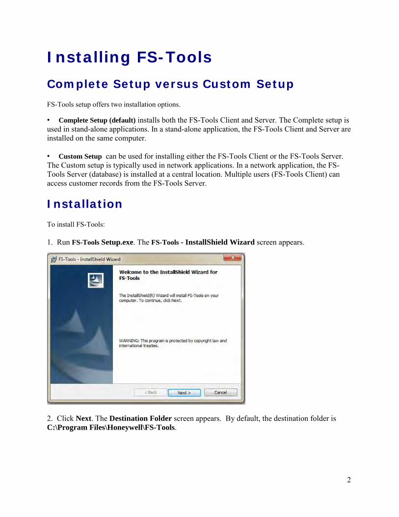
9. In the Setup Type screen, select Network setup to install only the FS-Tools Client. ClickNext. The Custom Setup screen appears.
Installing FS-Tools
6
10. In the Custom Setup screen, select the option in the Server list to disable the FS-ToolsServer, to install only the FS-Tools Client. Click Next.
11. The Database Server Information screen appears.

FS-Tools Programming Guide for the 200 Point Addressable Panel
7
12. Select/type the IP address of the FS-Tools Server from the Database Server drop-downlist. Click Next.
13. The Ready to Install screen appears. Click Install.
14. A screen indicating the installation progress appears.

Installing FS-Tools
8
15. Click Finish after the installation is complete to close the FS-Tools - Installation Wizard.
Windows Vista Users If you want to install or upgrade FS-Tools in a Windows Vista operating system, the User Account Control (UAC) feature needs to be turned off. To turn off the UAC:
1. Click Start > Control Panel. The Control Panel window appears.
2. In the Control Panel window, click User Accounts.
3. In the User Accounts window, click User Accounts.
4. On the right page of the User Accounts window, click Turn User Account Control on or off.
5. If the UAC is currently configured in Admin Approval Mode, the User Account Control message box appears. Click Continue. The Turn User Account Control on or off window appears.
6. Clear the Use User Account Control (UAC) to help protect your computer check box and then click OK. A message box appears.
7. Click Restart Now to apply the change immediately or click Restart Later, and then close the User Accounts tasks window.
8. Install FS-Tools.
9. Turn the UAC back on by reversing the steps above.

FS-Tools Programming Guide for the 200 Point Addressable Panel
9
System Requirements Before you begin the setup process, ensure that your laptop or computer has the minimum hardware, software, and support components.
Component Requirement
Operating System
Windows XP, Windows Vista, Windows7, Windows 8, Windows 8.1, Windows 10 with Microsoft® Excel software
Processor 16 GHz P4 Processor
RAM Minimum 256MB
Cache 512K
Hard Disk Drive 20GB with a minimum of 1GB available
Graphics Card and Monitor 1024 x 768 pixel resolution or higher
Color Palette 256 colors, True Color, Font size: small or large
Communication USB Drive
Printer HP LaserJet

Installing FS-Tools
10
Note: Uninstalling FS-Tools removes the FS-Tools software but not the database. You must delete the database manually by navigating to the installed location and deleting the database folder. FS-Tools software will not work correctly if you install a later version of FS-Tools software without deleting the previous version database.
Uninstalling FS-Tools FS-Tools can be uninstalled using the Control Panel.
1. Click Start, and then choose Control Panel. The Control Panel window appears.
2. Double-click Programs and Features.
3. From the list of installed programs, select FS-Tools.
4. Click Uninstall. A message asking for your confirmation appears.
5. Click Yes. The FS-Tools application is uninstalled.

11
Getting Started Logging On To log on to FS-Tools:
Click Start, and then choose Programs > FSTools > FS-Tools.
Or
Double click the icon on the desktop.
The initial customer details window appears.
On this screen, you can add a customer, select their panel type, and then begin to configure the fire system.
Exiting
To exit the FS-Tools application, click on the upper-right corner of the window
Or
Click Exit from the File menu.
Getting Started
12
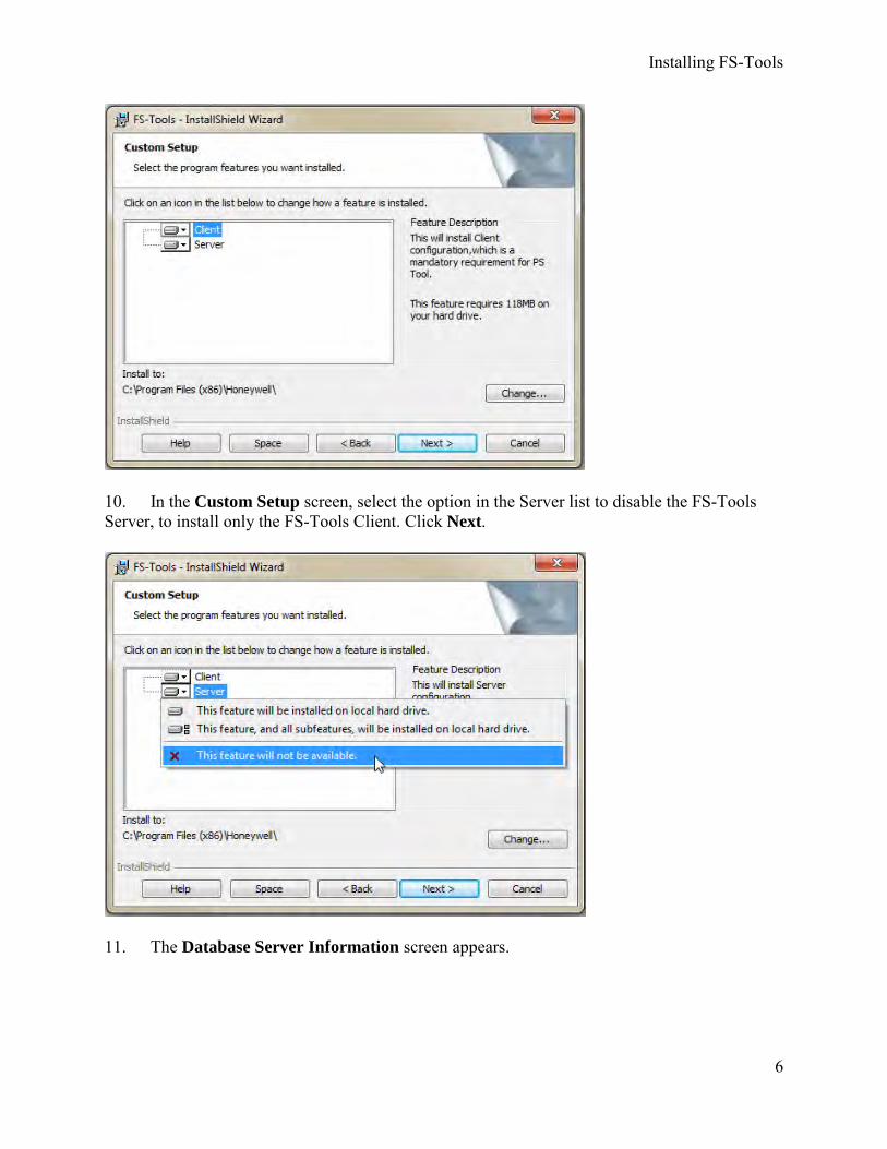
Customer Screen Using FS-Tools, you can configure the settings of the 198 Point Addressable Fire Alarm Control Panel (FACP) and in addition, maintain the details of the fire panel customers.
Before you can configure the fire panel settings, you need to add the customer information to the FS-Tools database. Customer details such as First Name, Last Name, Address, Contact Number, and Panel Type (panel version) must be added.
When you log on to FS-Tools, the customer screen appears. This screen consists of the Customer List and the Customer Details sections. The Customer List section displays the list of existing customers for the fire panel and the Customer Details section displays the details for a selected customer. Upon first login of the application, the Customer List section will be empty. The Customer Details section will display New Customer, prompting an entry into the database.
The initial customer screen in FS-Tools allows you to:
• Add a new customer.
• Find an existing customer.
• Select and configure a fire panel for a customer.
• Edit customer details.
• Delete a customer record.

FS-Tools Programming Guide for the 200 Point Addressable Panel
13
Adding a New Customer A new customer can be the protection services staff for campuses such as museums, universities, or schools, where the 198 Point Addressable Fire Alarm system is installed. Details such as First Name, Last Name, Address, etc. can be added for each customer.
To enter new customer details:
1. Click New Customer.
2. Fill out the First Name, Last Name, Address 1, Address 2, City, State, Zip Code, and ContactNumber fields for the customer. Fields marked with * are mandatory.
3. Select the appropriate fire panel type from the drop-down box.
4. Click Save. A confirmation message appears.
5. Click Yes. The details for the new customer are added in the FS-Tools database.
Getting Started
14
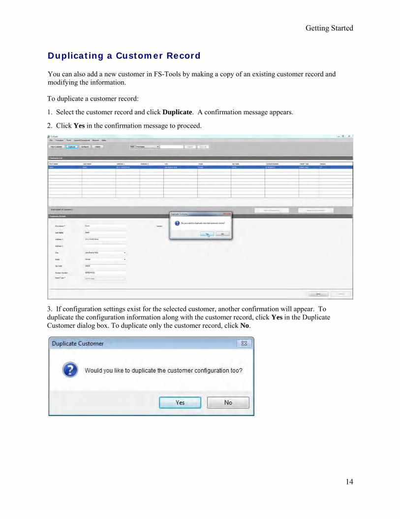
To duplicate a customer record:
1. Select the customer record and click Duplicate. A confirmation message appears.
2. Click Yes in the confirmation message to proceed.
3. If configuration settings exist for the selected customer, another confirmation will appear. Toduplicate the configuration information along with the customer record, click Yes in the DuplicateCustomer dialog box. To duplicate only the customer record, click No.
Duplicating a Customer Record
You can also add a new customer in FS-Tools by making a copy of an existing customer record and modifying the information.

FS-Tools Programming Guide for the 200 Point Addressable Panel
15
2. In the text box provided, type the keyword for the search.
3. Click Search. The search results are displayed in the Customer List.
To retrieve all customer records, click Show All. All the customer records are retrieved in the Customer List.
Editing Customer Details You can update all the customer details using the Edit option.
To edit the customer details:
1. Select the customer record you want to edit. You many want to use the Find option.
2. Update the customer data in the Customer Details section.
3. Click Save. If you select another customer record without saving, you are prompted to savethe updated record.
4. Click Yes to update the customer details in FS-Tools.
Configuring a Fire Panel for a Customer Using the Configure option, you can configure all the fire alarm system settings. Before you configure the fire panel, new customer details must be added to the FS-Tools database.
To configure the fire panel for a customer:
1. Using the Find option, select the customer record.
2. Click Configure.For more information about configuring the fire panels, click here.
Finding a Customer Using the Find option you can find the details for a customer when there are multiple customer records. You can search by the First Name, Last Name, Address 1, Address 2, City, State, Zip Code, or the Contact Number. The Search results are displayed in the Customer List section.
To find a customer:
1. In the Find list, select the field for the search. Options include First Name, Last Name,Address 1, Address 2, City, State, Zip Code, Contact Number, Panel Type, or Version,

Getting Started
16
To delete a customer record:
1. Select the customer record you want to delete. You may want to use the Find option.
2. Click Delete. A message asking for confirmation appears.
3. Click Yes to delete the customer record. If configuration settings exist for the customerrecord, a message asking for confirmation to delete the configuration information is displayed.The following screen appears:
Deleting a Customer Record
When a customer account is considered inactive, you can delete the customer record. The saved configuration information for the fire panel also gets deleted when you delete a customer record.
4. To delete the customer record along with the configuration information, click Yes.

17
Configuring the Fire Panel Using FS-Tools, you can configure fire panel settings. This involves:
• configuring the settings for input and output modules.
• configuring the fire panel settings such as date and time, banner display, fire panelpasswords, etc.
• configuring the SLC loop setup for the detectors and modules.
• verifying the SLC loop setup.
• simulating the setup to evaluate SLC loop.
• modifying the customer details in the server.
After you configure the fire panel settings, you must connect the computer to the fire panel and download the configuration settings. In addition, you can upload the configuration information from the fire panel, and view the fire alarm system settings in FS-Tools.
Selecting Configuration Type 1. Using the Find option from the initial screen, if necessary, select a customer record. For moreinformation, see Finding a Customer.
2. Click Configure to program the fire panel settings. The Configuration Type dialog boxappears.
3. In the Select Configuration list select the default option Factory Default, if you areconfiguring for the first time or select a previously saved configuration which appears in the list.
4. Click OK. The System Info programming page appears.

Configuring the Fire Panel
18
Configuring System Info In FS-Tools, configuring the system information involves the following steps:
1. Configuring the communicator settings:
a. Central Station
b. Primary Central Station
c. Secondary Central Station
2. Configuring the input/output modules:
a. Relays
b. Zones
c. Special Zones
d. NACs
3. Configuring the general system settings which include the timers, clock format, troublereminder, and other settings
4. Configuring the ANN-Bus, Primary and Secondary
5. Editing the Function Keys' actions.
6. Configuring the SLC Loop Setup:
a. Detectors
b. Modules

19
FS-Tools Programming Guide for the 200 Point Addressable Panel
Communicator Settings
Central Station
The optional IP/POTS Communicator card transmits system status (alarms, troubles, AC loss, etc.) to a Central Station via the public switched telephone network and via an ethernet connection.
In FS-Tools, you must enable reporting from the communicator to report the fire alarm system status, alarm, and trouble conditions to the central station. The System Info -> Communicator Settings -> Central Station pane appears after you select the configuration type.
Note: All programming features may not be applicable to the your panel's version of software. See the following pages to learn more.
Click Save to Database to save the configuration to the FS-Tools database.
Click Save as Template to use these settings as a template for future panel's settings.
Click Next or click Primary Central Station in the left pane, to view the Primary Central Station configuration pane.

20
Click IPOTS-COM Installed if the IPOTS-COM telephone and IP communicator card is installed on the PCB. The communicator comes pre-installed on some models.
Trouble Call Limit: This field option limits the number of communicator trouble calls to the Central Station, to a programmed amount between 0 and 99, for each unique trouble within a 24 hour period. Separate limit counters keep track of each unique type of trouble. Note that the number of phone line (communication) faults called to the Central Station are not limited by this feature.
Reporting Style: Setting the Report Style to Point will program the IPOTS-COM to report individual point status to the Central Station. The control panel is capable of monitoring a total of 198 addressable devices. Setting the Report Style to Zone will program the communicator to report zone status to the Central Station. The control panel is capable of monitoring a total of 99 individual zones.
Central Station
If telephone lines are connected to the IPOTS-COM board at J4 (Line 1) and/or J5 (Line 2), ensure that the Enabled checkbox is selected.
The Supervised Phone Line feature allows the user to disable the supervision of Phone Lines when using an alternate means of secondary transmission path. The factory default setting is Phone Line supervised.
Type: Select whether each phone line connected to the communicator uses Touch Tone format or one of two different types of the Rotary format.
Gains Settings
The Gains value is the telephone’s transmitting “volume control”. The Gains value can be adjusted for when the telephones lines are in use for Dialing and Reporting.
Select Low, Normal, or High from the drop-down boxes.
Test Times
Select the desired Test Time Interval (6, 8, 12, or 24 hours) to send the test report to the primary central station.
Enter the Test Start Time to program the time at which the communicator will transmit the 24 Hour Test to the Central Station. Enter a four digit number using military time (0000 refers to 12:00AM and 2359 refers to 11:59PM).

Supervision Settings: Choose one of the following from the drop-down menu where the Supervision Interval is the time from the “ping” at AlarmNet to the FACP, and the Fault Time is the duration of the communication loss between the FACP and the cell/ethernet infrastructure (eg. cell tower).
• 2010 IP+CELL: Supervision Interval: 24 Hours, IP Fault Time: 1 Hour, GSM Fault Time: 1Hour
• 2010 IP: Supervision Interval: 5 min, IP Fault Time: 5 min
• 2013 IP+CELL: Supervision Interval: 6 Hours, IP Fault Time: 1 Hour, GSM Fault Time: 1Hour
• 2013 IP: Supervision Interval: 1 Hour, IP Fault Time: 1 Hour
If the internet router used by the IPOTS-COM is configured for DHCP (Dynamic Host Configuration Protocol) where addresses are automatically assigned by the router, click the
FS-Tools Programming Guide for the 200 Point Addressable Panel
21
DHCP Enabled checkbox. Note that this field is automatically selected when the IPOTS-COM Installed checkbox is selected as most routers are configured for DHCP protocol.
Static Settings: These addresses must be set manually if the internet router is not configured for DHCP. Deselect DHCP Enabled to activate these fields for editing.
Supervision: Select the desired supervision type from the drop-down box.
Setting: Supervision Interval: IP Fault Time: GSM Fault Time:
2010 IP 5 minutes 5 minutes N/A
2010 IP + CELL 24 hours 1 hour 1 hour
2013 IP 1 hour 1 hour N/A
2013 IP + CELL 6 hours 1 hour 1 hour
Central Station Event Codes
Here you can customize the event codes. Event codes are the Communicator's way of telling the central station what type of event is taking place. These codes vary based on the selected communication format. When the communication format is selected, the default event code values are shown. They may be changed in this section. Enter zero(es) to disable the reporting of a specific event.

Primary/Secondary Central Station
The FACP reports the fire alarm system status, alarms, and trouble events to the central station. The primary and secondary central station screen are almost identical and allow you to configure the Communication Path, Communication Format, Central Station Account Information, and Event Codes.
See the following pages to learn more.
Primary/Secondary Central Station
22
Click Save to Database to save the configuration.
Click Next or click Secondary Central Station in the left pane to configure the secondary central station.
Click Prev to go back to the central station settings.
Central Station Settings
Communication Path: Select the communication method for contacting the central station. POTS (Plain Old Telephone Service), Ethernet, or Cellular are available from the drop-down menu.
Note: Use of the CELL-CAB or CELL-MOD GSM Communicator Card is required for Cellular reporting to central station.
When POTS is selected:
Enter the Phone Number of the primary/secondary central station that the communicator will be contacting. You can enter a maximum of 20 characters with valid entries being 0 to 9 and A - C where A = *, B = # and C = 2 second pause.
Select the Communication Format of the reports sent to the primary control station. The primary event codes are displayed based on the communication format used. The Communication Format is determined by the type of receiver that the communicator is transmitting to. Consult your Central Station for proper selection or consult our factory representatives. For any format chosen, the control panel automatically programs all of the event codes. This field is only selectable when POTS is chosen as the communication path.
FS-Tools Programming Guide for the 200 Point Addressable Panel
23
Type the Account Code for the panel assigned by the central station. Each panel has a unique account code depending on the primary central station and the communication format being used.
Type the City ID for the panel assigned by the central station.
Type the Central Station ID for the panel assigned by the central station.

Input/Output
Relays/Zones
From the Input/Output pane, you can configure the FACP's relays, zones, special zones and NACs.
Input/Output
24
Click Save to Database to save the configuration.
Click Next or click NAC 1 in the left pane to start configuring the NAC circuits.
Click Prev to go back to the secondary central station settings.

The FACP offers one fixed and two fully programmable Form-C dry contact relays. Relay 1 is factory default programmed as Alarm and programmable Relay 3 is factory default programmed as Supervisory. The relay labeled Relay 2 is fixed as a Trouble relay and cannot be changed. It is a fail-safe relay which will transfer on any trouble or total power failure. Select the desired option for Relays 1 and 3 from the drop-down box.
Possible options are: Alarm, Supervisory, Supervisory AR, Trouble, Communication Fail, Process Monitoring, Process Monitoring AR, AC Loss, Hazard, Medical, and Silenceable Alarm.
Notes:
1. AR (AutoResettable) in SUPERVISORY AR and PROCESS MONITORING AR means thata relay with the Supervisory and/or Process Monitor type code, when activated, willautomatically reset when the corresponding condition is cleared.
2. A relay programmed with the Silenceable Alarm type will activate upon any alarm anddeactivate when the FACP Alarm Silenced LED is illuminated.
Zones
Zone Types: must be programmed only if a Communicator, programmed for zone reporting, is installed on the control panel. From the drop-down box, select the type of zone desired for each installed zone. Zone Types are only relevant for Central Station reporting. Changing a zone type will only change how it is reported to the Central Station. If a tornado zone is required, choose Zone Type “Hazard”. Important! Selecting WATERFLOW will assign a Waterflow silenceable zone type to the selected zone. Any signaling devices programmed to the same zone can be silenced by pressing the Alarm Silence key or by using the auto-silence feature.
Enabled/Disabled: select Enable to enable the selected zone. If you select Disable, the zone is disabled by the fire panel, preventing the zone circuit from reporting alarms and troubles to the panel. Disabling a zone disables all the functionalities associated with that zone.
Zone Audio Message: select the desired message, if any, to play when a selected zone activates. 14 messages are available if the mass notification audio system is installed. 5 messages are available if the legacy voice evacuation panel is installed.
FS-Tools Programming Guide for the 200 Point Addressable Panel
Relays
25

Zones 96, 97, 98, and 99 can be programmed for normal zone operation or for special purpose applications.
Zone 96: When Zone 96 is programmed On, a Local Alarm activation of any smoke detector will cause Zone 96 to activate. By assigning Zone 96 to a control module in the Programming Zone Assignment Screen, an output device connected to the control module can be used to indicate a local alarm condition in the control panel. Local Alarm Zone alarms are not reported to the Central Station.
Zone 97: When Zone 97 is selected as a special zone, a PAS (Positive Alarm Sequence) activation of any smoke detector will cause Zone 97 to activate. By assigning Zone 97 to a control module in the Zone Mapping section, an output device connected to the control module can be used to indicate a PAS condition in the control panel. Do not assign Zone 97 to a Notification Appliance Circuit when using this zone to indicate a PAS condition.
Zone 98: When Zone 98 is selected as a special zone, a Pre-signal activation of any device will cause Zone 98 to activate. By assigning Zone 98 to a control module in the Zone Mapping Section, an output device connected to the control module can be used to indicate a Pre-signal condition in the control panel. Do not assign Zone 98 to a Notification Appliance Circuit when using this zone to indicate a Pre-signal condition.
Zone 99: When Zone 99 is selected as a special zone, any time a NAC programmed for two-stage operation moves into the 2nd stage, Z99 will activate. Any control modules assigned to Special Zone 99 will also activate.
Special Zones
Relays/Zones
26
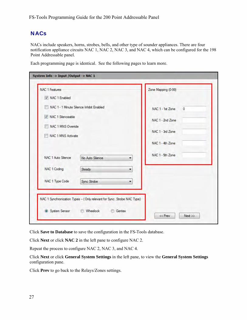
NACs
NACs include speakers, horns, strobes, bells, and other type of sounder appliances. There are four notification appliance circuits NAC 1, NAC 2, NAC 3, and NAC 4, which can be configured for the 198 Point Addressable panel.
Each programming page is identical. See the following pages to learn more.
FS-Tools Programming Guide for the 200 Point Addressable Panel
27
Click Save to Database to save the configuration in the FS-Tools database.
Click Next or click NAC 2 in the left pane to configure NAC 2.
Repeat the process to configure NAC 2, NAC 3, and NAC 4.
Click Next or click General System Settings in the left pane, to view the General System Settings configuration pane.
Click Prev to go back to the Relays/Zones settings.

NAC Features
To enable each NAC, click the NAC X Enabled checkbox. If you do not select the Enable checkbox, the NAC is disabled and the fire panel prevents the selected NAC from activating its devices.
NACs
28
Click Minute Silence Inhibit Enabled to enable the silencing of the audible devices in NAC X, only after 60 seconds. If this option is enabled, the audible devices can be silenced by pressing the Alarm Silence key, only after 60 seconds.
Click Silenceable to indicate whether the NAC can be silenced by pressing the Alarm Silence key. If the Silenceable option is not enabled, the selected NACs cannot be silenced by pressing the Alarm Silence key or by the Auto Silence feature.
Select the delay time for Auto Silence from the list to automatically silence the main circuit board silenceable NACs after a programmed length of time. This option is disabled if the option is not selected.
Click MNS Override to allow the Mass Notification System to override the FACP and turn off an active NAC OR prevent the NAC from activating during a mass notification event. Click MNS Activate to activate NACs on the FACP when an MNS Event occurs on the Mass Notification System. This allows you to use the NACs on the FACP for MNS events as well as fire events. By enabling this setting on the NAC, the NAC will activate when an MNS event occurs.
The MNS Activate and MNS Override settings cannot be enabled at the same time.
Select the Coding option to specify the type of output the main circuit board notification appliances generates when activated. Click here for more information about each coding selection. Select the NAC device type from the list in the Type Code drop-down box. Type code options are: Bell, Horn, Strobe, Synced Strobe (Synchronized to manufacturer), Strobe Sil Sync (same as Synced Strobe but Silence turns off audible & visual devices), or Blank.
NAC Synchronization Types
Select the Synchronization Type which can be System Sensor, Wheelock, or Gentex. Synchronization is a panel feature that controls the activation of notification appliances in such a way that devices turn on and off at exactly the same time. For more information about synchronization, see Synchronized NAC Operation. NAC Synchronization Type can be selected only for the Sync Strobe or Strobe Sil Sync NAC Type Code.
NAC Zone Mapping
Under Zone Mapping, enter the three digit number corresponding to the zone assigned to NAC X. A maximum of five zones can be configured for each main circuit board NAC. The factorydefault for an unprogrammed device is Z000 for general/local alarm zone.

General System Settings In this screen, you can configure the FACP's general system settings. See the following page to learn more.
Click Save to Database to save the configuration in the FS-Tools database.
Click Next or click Global Options in the left pane to configure the global ANN-BUS settings.
Click Prev to go back to the NAC settings.
FS-Tools Programming Guide for the 200 Point Addressable Panel
29

PAS (Positive Alarm Sequence) delay can be programmed for a delay of 0-180 seconds. This option is unavailable if the Canadian Option if selected.
Pre-Signal delay can be programmed for a delay of 0-180 seconds. This option is unavailable if the Canadian Option if selected.
Waterflow Retard delay can be programmed for a delay of 0-90 seconds.
AC Loss delay can be programmed for a delay of 0-23 hours. The factory default setting is 2 hours.
Control Module Delay can be programmed for a delay of 0-180 seconds.
The Trouble Reminder feature provides an audible reminder that an alarm or trouble still exists on the FACP after the control panel has been silenced. The control panel piezo sounder will pulse once every 15 seconds during an alarm and every two minutes during a trouble condition, after the Alarm Silence or Acknowledge key is pressed. The piezo will continue to sound at these rates until the alarm or trouble condition is cleared. If the trouble condition is not cleared within the selected 4 or 24 hours, the panel will reactivate the trouble sounder and retransmit the trouble condition to the central station if connected.
The Waterflow Devices Silenceable option provides the ability to silence any output circuit activated by a monitor module programmed as a waterflow type.
The Canadian Option feature, when enabled, configures the FACP with the following as required by Canada:
• The following monitor module type codes are not available: monitor, non-latchingsupervisory, non-latching drill, non-latching process monitor, hazard, tornado, medical alert
• Addressable ionization smoke detector sensitivity is automatically monitored using Canadianspecifications.
• The Positive Alarm Sequence, the Pre-Signal option, the Auto-Silence option, and theSilence Inhibit Timer are not available for Canadian applications.
• The Auto-silence timer is fixed at 20 minutes and cannot be changed.
• The F1 function key is automatically configured to perform a manual alarm signal activationwhen pressed.
• The F2 function key is automatically configured to perform a two-stage bypass when pressed.
For Canadian applications, remote annunciation must be done using the secondary ANN-BUS.
The Timers option allows you to set the times for a:
Timers
General System Settings
30

The MNS Override option allows the Mass Notification System to override the FACP’s specified NACs and control modules. When the Canadian Option is enabled, the MNS Override feature will become unavailable.
Some mass notification installations may require that the activation of the audio system results in an override of an active fire notification at the FACP. This is determined by a risk assessment in accordance with the local AHJ. The FACP provides the flexibility to accommodate override or non-override operation. For override operation, FACP NACs and/or other SLC control modules may be deactivated while the mass notification event is active. No other FACP operation is overridden or interrupted. If override operation has been selected, notification for a fire event will resume upon termination of the mass notification event at the audio system.
The 4XTM Supervision Enable checkbox must be selected if a 4XTM(F) module is installed on the FACP.
The Battery Charger Enable option allows you to disable the onboard battery charger in the event an external battery charger is being used.
The Remote Sync Enable option allows you to sync NAC devices connected to an external power supply. The devices will sync will NAC1 on the FACP. Remote Sync requires wiring from the Remote Sync output terminal block to the Remote sync input on the FCPS power supply.
Daylight Savings Time
If selected, the control panel will automatically update the time for daylight savings time.
Use the drop-down boxes to select the week and month for daylight savings start and end times.
Clock Format
The Clock Format feature allows you to set the time display format (24 hour or 12 hour) in the FACP memory.
Loop Style
Loop Style option allows you to select the loop style for the panel's SLC (Signaling Line Circuit). The panel may be wired in Class B (Style 4), a two-wire circuit starting at the panel and ending at the last device, or Class A (Styles 6 or 7), a four-wire circuit starting at the panel going out to all the devices, and ending back at the panel. Style 7 wiring uses isolator modules, one on each side of the loop.
31
FS-Tools Programming Guide for the 200 Point Addressable Panel

Protocol Type
Protocol Type: The FACP operates in two SLC polling styles, LiteSpeed or CLIP (Classic Loop Interface Protocol). LiteSpeed is a communication protocol that greatly enhances the speed of communication between analog intelligent devices. This is the default mode of operation for this FACP. CLIP mode polls devices in sequential order. All addressable FACPs can operate in CLIP mode.
Note that the legacy devices can operate only in CLIP mode while the newer devices are compatible with CLIP and LiteSpeed modes of operation. If any legacy, CLIP mode device is installed on the system, the Protocol type must then be set to CLIP.
Language Support
Language Support: The FACP is capable of displaying panel display text in either English or French. Select the desired language from the drop-down menu.
Aux Settings
The FACP provides two 24VDC outputs for powering auxiliary devices.
The Aux power is configured for Non-Resettable power (suitable for powering annunciators). If Resettable Power is desired instead (suitable for powering smoke detectors), ensure that the Resettable checkbox is selected.
Banner Display
The Banner Display option allows you to choose from either a factory default or custom banner for the top two lines of the LCD display on the fire panel. You can change the factory default to a custom defined readout when the fire panel is in normal condition. A maximum of 20 characters, including spaces, can be entered for each line on the display.
Configuring the Fire Panel
32

ANN-Bus Settings
Global Options
The ANN-Bus is a communication circuit on the fire panel over which different ANN devices can be installed to communicate with the FACP. You can configure the ANN-Bus when any ANN devices are installed. See the following pages to learn more.
Refer to the ANN-BUS Guidelines for more information when using both the primary ANN-BUS and the secondary ANN-BUS.
33
FS-Tools Programming Guide for the 200 Point Addressable Panel
Click Save to Database to save the configuration in the FS-Tools database. Click Next or click Primary ANN Bus in the left pane configure the Primary ANN-Bus Settings.Click Prev to go back to the General System Settings pane.

ANN-BUS Guidelines
• A variety of optional annunciation devices can be connected to an ANN-BUScommunication circuit. ANN Series devices can be connected to the primary communicationcircuit (EIA-485) terminals on TB9. A secondary communication circuit for these devices isavailable at TB10. Each ANN-BUS communication circuit supports up to eight (8) annunciators.
ANN-Bus Settings
34
• When operating two ANN-BUS circuits, only one ANN-S/PG Printer module can be used inthe system.
• The panel is capable of operating a primary ANN-BUS (TB9) and a secondary ANN-BUS(TB8) simultaneously.
• Only one audio system (ECC-50/100 or ACC-25/50) may be connected to the ANN-BUS.
Primary/Secondary ANN Bus
Click Yes to enable the Primary and/or Secondary ANN-Bus. You must enable the ANN-Bus if any modules are connected to the Primary ANN-Bus terminal at TB9 or to the Secondary ANN-Bus terminal at TB10 on the main circuit board.
The primary ANN-Bus is capable of operating in Class A configuration. Select the checkbox if the primary Ann-Bus is wired for Class A operation.
The following are the compatible devices that may be available for connection to the ANN-Bus communication circuit.
• ANN-80 LCD Annunciator
• ANN-100 (for FM and Canadian applications)
• ANN-S/PG Serial/Parallel Printer Interface Module
• ANN-I/O LED Driver Module
• ANN-(R)LED LED Annunciator Module (alarm, trouble, supervisory LEDs)
• ANN-RLY Relay Module
• ANN-ACC Voice Evacuation Panel
• ANN-ECC Mass Notification Panel

FS-Tools Programming Guide for the 200 Point Addressable Panel
35
ANN-S/PG Options
The ANN-S/PG options allows you to the connect a remote serial or parallel printer to the FACP. This helps you to log system events, detector status reports and event history. If Parallel port is selected, you can supervise and set the offline timer for the printer. If Serial port is selected, you can set the Baud Rate, Parity, Data Bits, and Stop Bits.
Under ANN S/PG options, select the type of Port for the printer connection, either Serial or Parallel.
• If you select Parallel port, the following fields are activated:
• In the Printer Supervision list, select to enable or false to disable printer supervision.
• In the Offline Timer box, enter offline for delay, between 0 and 255 seconds, before loss ofprinter supervision is reported as a trouble.
• If you select Serial port, the following fields are activated:
• In Baud Rate list, select a baud rate in the range 2400, 9600, or 19200.
• In Parity list, select Even, Odd, or None.
• In Data Bits list, select 7 or 8 bits.
• In Stop Bits list, select 0.5, 1, or 2.
ANN-LED Options
The Piezo Enable option allows you to select whether the piezo sounder on any installed ANN-LED module will ever sound. Select yes to enable or no to disable.
The Lamp Test Enable option allows you to select whether the Lamp Test button on any installed ANN-LED annunciator will function normally or always be ignored. Select yes to enable or no to disable.
The Silence Button Enable option allows you to select whether the Silence button on any installed ANN-LED annunciator will function normally or always be ignored. Select yes to enable or no to disable.

ANN-Bus Settings
36
ANN-80 Options
The Lock Enable option allows you to select whether or not any installed ANN-80 annunciator must be unlocked by its key before any annunciator key presses will function. Select yes to enable (annunciator must be unlocked for keys to function) or no to disable (lock position is ignored).
The Acknowledge/Step Enable option allows you to select whether the Ack/Step button on any installed ANN-80 annunciator will function normally or always be ignored. Select yes to enable (Ack/Step button functions normally) or no to disable (Ack/Step button never functions).
The Silence Enable option allows you to select whether the Silence button on any installed ANN-80 annunciator will function normally or always be ignored. Select yes to enable (Silence button functions normally) or no to disable (Silence button never functions).
The Piezo Enable option allows you to select whether the piezo sounder on any installed ANN-80 module will ever sound. Select yes to enable or no to disable.
The Reset/Lamp Enable option allows you to select whether the Reset button on any installed ANN-80 annunciator will function normally or always be ignored. Select yes to enable (Reset button functions normally) or no to disable (Reset button never functions).
The Drill/Sounder Enable option allows you to select whether the Drill button on any installed ANN-80 annunciator will function normally or always be ignored. Select yes to enable (Drill button functions normally) or no to disable (Drill button never functions).

37
FS-Tools Programming Guide for the 200 Point Addressable Panel
Primary/Secondary ANN-Bus
For each enabled ANN-Bus address, select the module type from the drop-down box. The Primary and Secondary ANN-Bus screens are identical.
Available ANN-Bus modules may include the:
• ANN-80 LCD Annunciator
• ANN-100 LCD Annunciator
• ANN-I/O LED Driver Module
• ANN-S/PG Serial/Parallel Printer Interface Module
• ANN-LED Annunciator Module
• ANN-RLED Annunciator Module
• ANN-RLY Relay Module
• ANN-ACC Voice Evacuation Panel
• ANN-ECC Mass Notification Panel
The ANN-I/O, ANN-(R)LED, and ANN-RLY require input in the status field. After selecting one of these devices from the drop-down menu, double-click in the "Status" field to finish device setup.

Primary/Secondary ANN-Bus
38
ANN-I/O
Select whether the ANN-I/O will annunciate either Point (addressable device address) information or Zone information and select the Point range or Zone range to be annunciated. If a point range is desired, select either addressable detectors or addressable modules to be annunciated.
ANN-I/O Point Option
If Point is selected as the module option, the first ten LEDs on the first ANN-I/O module will display the system status information. The remaining 30 LEDs on the first module and 40 LEDs on each additional module will display the active/alarm status of each point in the Point Range programmed for that particular module. The points that will be annunciated on a particular ANN-I/O module depend on the programming options selected as far as the device type (detector or module) to be annunciated. The LED assignments for each ANN-I/O module will be as follows.
Module LED Point Range 031-070 Point Range 071-0991 AC Fault Point 031 Point 071 2 Fire Alarm Point 032 Point 072 3 Supervisory Point 033 Point 073 4 Trouble Point 034 Point 074 5 Alarm Silenced Point 035 Point 075 6 Earth Fault Point 036 Point 076 7 Battery Fault Point 037 Point 077 8 Charger Fault Point 038 Point 078
Point Range 001-030
9 NAC Fault Point 039 Point 079 10 Disabled Point 040 Point 080

14 Point 004 Point 044 Point 084 15 Point 005 Point 045 Point 085 16 Point 006 Point 046 Point 086 17 Point 007 Point 047 Point 087 18 Point 008 Point 048 Point 088 19 Point 009 Point 049 Point 089 20 Point 010 Point 050 Point 090 21 Point 011 Point 051 Point 091 22 Point 012 Point 052 Point 092 23 Point 013 Point 053 Point 093 24 Point 014 Point 054 Point 094 25 Point 015 Point 055 Point 095 26 Point 016 Point 056 Point 096 27 Point 017 Point 057 Point 097 28 Point 018 Point 058 Point 098 29 Point 019 Point 059 Point 099 30 Point 020 Point 060 Not Used 31 Point 021 Point 061 Not Used 32 Point 022 Point 062 Not Used 33 Point 023 Point 063 Not Used 34 Point 024 Point 064 Not Used
FS-Tools Programming Guide for the 200 Point Addressable Panel
39
11 Point 001 Point 041 Point 081 12 Point 002 Point 042 Point 082 13 Point 003 Point 043 Point 083
35 Point 025 Point 065 Not Used 36 Point 026 Point 066 Not Used 37 Point 027 Point 067 Not Used 38 Point 028 Point 068 Not Used 39 Point 029 Point 069 Not Used 40 Point 030 Point 070 Not Used

Primary/Secondary ANN-Bus
40
ANN-I/O Zone Option If Zone is selected as the module option, the first ten LEDs on the first ANN-I/O module will display the system status information. The remaining 30 LEDs on the first module and 40 LEDs on the remaining modules will display the active/alarm status of each zone in the Zone Range programmed for that particular module. The LED assignments for each ANN-I/O module will be as follows. Module LED 1 AC Fault Zone 030 Zone 070 2 Fire Alarm Zone 031 Zone 071 3 Supervisory Zone 032 Zone 072 4 Trouble Zone 033 Zone 073 5 Alarm Silenced Zone 034 Zone 074 6 Earth Fault Zone 035 Zone 075 7 Battery Fault Zone 036 Zone 076 8 Charger Fault Zone 037 Zone 077 9 NAC Fault Zone 038 Zone 078 10 Disabled Zone 039 Zone 079 11 Zone 000 Zone 040 Zone 080 12 Zone 001 Zone 041 Zone 081 13 Zone 002 Zone 042 Zone 082 14 Zone 003 Zone 043 Zone 083 15 Zone 004 Zone 044 Zone 084 16 Zone 005 Zone 045 Zone 085 17 Zone 006 Zone 046 Zone 085 18 Zone 007 Zone 047 Zone 086 19 Zone 008 Zone 048 Zone 087
Zone Range 000-029 Zone Range 030-069 Zone Range 070-099
20 Zone 009 Zone 049 Zone 088 21 Zone 010 Zone 050 Zone 090 22 Zone 011 Zone 051 Zone 091 23 Zone 012 Zone 052 Zone 092 24 Zone 013 Zone 053 Zone 093 25 Zone 014 Zone 054 Zone 094 26 Zone 015 Zone 055 Zone 095 27 Zone 016 Zone 056 Zone 096 28 Zone 017 Zone 057 Zone 097 29 Zone 018 Zone 058 Zone 098 30 Zone 019 Zone 059 Zone 099 31 Zone 020 Zone 060 Not Used 32 Zone 021 Zone 061 Not Used 33 Zone 022 Zone 062 Not Used 34 Zone 023 Zone 063 Not Used

Select whether the ANN-LED will annunciate either Point information (addressable device address) or Zone information and select whether the ANN-LED will annunciate alarms only or alarms, troubles, and supervisories. If a point range is desired, select either addressable detectors or addressable modules to be annunciated.
ANN-(R)LED
35 Zone 024 Zone 064 Not Used 36 Zone 025 Zone 065 Not Used 37 Zone 026 Zone 066 Not Used 38 Zone 027 Zone 067 Not Used 39 Zone 028 Zone 068 Not Used 40 Zone 029 Zone 069 Not Used
FS-Tools Programming Guide for the 200 Point Addressable Panel
41

Primary/Secondary ANN-Bus
42
ANN-LED Point Option
Alarm Only (for use with ANN-RLED module)
If Point is selected as the module option and the module is programmed to annunciate alarms only, the first ten LEDs on the first ANN-LED module will display the system status information. The remaining 30 LEDs on the first module and the last 30 LEDs on each additional module will display the active/alarm status of each point in the Point Range programmed for that particular module. The points that will be annunciated on a particular ANN-LED module depend on the programming options selected and the device type (detector or module) to be annunciated. The LED assignments for each ANN-LED module will be as follows.
Alarm Silenced NAC 1 Fault NAC 2 Fault NAC 3 Fault Earth Fault Battery Fault Charger Fault Disabled Point 001
Active/Alarm Point 002
Active/Alarm Point 003
Active/Alarm Point 004
Active/Alarm Point 005
Active/AlarmPoint 006
Active/Alarm Point 007
Active/Alarm Point 008
Active/Alarm Point 009
Active/Alarm Point 010
Active/Alarm Point 011
Active/Alarm Point 012
Active/Alarm Point 013
Active/Alarm Point 014
Active/Alarm Point 015
Active/AlarmPoint 016
Active/Alarm Point 017
Active/Alarm Point 018
Active/Alarm Point 019
Active Alarm Point 020
Active/AlarmPoint 021
Active/Alarm Point 022
Active/Alarm Point 023
Active/Alarm Point 024
Active/Alarm Point 025
Active/AlarmPoint 026
Active/Alarm Point 027
Active/Alarm Point 028
Active/Alarm Point 029
Active/Alarm Point 030
Active/AlarmANN-RLED Module #1 (Point Range 001-030)
NAC 4 Fault Maintenance
Not Used Not Used Not Used Not Used Not UsedNot Used Not Used Not Used Not Used Not UsedPoint 031
Active/Alarm Point 032
Active/Alarm Point 033
Active/Alarm Point 034
Active/Alarm Point 035
Active/AlarmPoint 036 Point 037
Active/Alarm Point 041
Active/Alarm Point 042
Active/Alarm Point 043
Active/Alarm Point 044
Active/Alarm Point 045
Active/AlarmPoint 047
Active/Alarm Point 051
Active/Alarm Point 052
Active/Alarm Point 053
Active/Alarm Point 054
Active/Alarm Point 055
Active/Alarm Point 057
Active/Alarm
Active/Alarm
Point 046Active/Alarm
Point 056Active/Alarm
Point 038Active/Alarm
Point 048Active/Alarm
Point 058Active/Alarm
Point 039Active/Alarm
Point 049Active/Alarm
Point 059Active/Alarm
Point 040Active/Alarm
Point 050Active/Alarm
Point 060Active/Alarm
ANN-RLED Module #2 (Point Range 031-060)
The LED assignments for the modules annunciating Point Ranges 061 - 090 and 091 - 099, will follow the same pattern as the second ANN-RLED module.

FS-Tools Programming Guide for the 200 Point Addressable Panel
43
Alarm, Trouble and Supervisory
If Point is selected as the module option, and the module is programmed to annunciate alarms, troubles and supervisories, the first ten LEDs on the first ANN-LED module will display the system status information. The remaining 30 LEDs on the first module and the last 30 LEDs on the remaining modules will display the alarm, trouble and supervisory status for each of the ten zones in the Point Range programmed for that particular module. The LED assignments for each ANN-LED module will be as follows.
Active/Alar4
Alarm Silenced NAC 1 Fault NAC 2 Fault NAC 3 Fault Earth Fault Battery Fault Charger Fault Disabled Point 001
Active/Alarm Point 002
Active/Alarm Point 003
Active/Alarm Point 004
Active/Alarm Point 005
Active/AlarmPoint 001 Trouble
Point 002 Trouble
Point 003 Trouble
Point 004 Trouble
Point 005 Trouble
Point 001 Supervisory
Point 002 Supervisory
Point 003 Supervisory
Point 004 Supervisory
Point 005 Supervisory
Point 006 Active/Alarm
Point 007 Active/Alarm
Point 008 Active/Alarm
Point 009 Active Alarm
Point 010 Active/Alarm
Point 006 Trouble
Point 007 Trouble
Point 008Trouble
Point 009 Trouble
Point 010 Trouble
Point 006 Supervisory
Point 007 Supervisory
Point 008 Supervisory
Point 009 Supervisory
Point 010 Supervisory
ANN-RLED Module #1 (Point Range 001-010)
NAC 4 Fault Maintenance
Not Used Not Used Not Used Not Used Not UsedNot Used Not Used Not Used Not Used Not UsedPoint 011
Active/Alarm Point 012
Active/Alarm Point 013
Active/Alarm Point 014
Active/Alarm Point 015
Active/AlarmPoint 011 Point 012
Trouble Point 011 Supervisory
Point 012 Supervisory
Point 013 Supervisory
Point 014 Supervisory
Point 015 Supervisory
Point 017Active/Alarm
Point 016Trouble
Point 017Trouble
Point 018 Trouble
Point 019Trouble
Point 020 Trouble
Point 017Supervisory
Trouble
Point 016Active/Alarm
Point 016Supervisory
Point 013Trouble
Point 018Active/Alarm
Point 017Supervisory
Point 014Trouble
Point 019Active/Alarm
Point 017Supervisory
Point 015Trouble
Point 020Active/Alarm
Point 017Supervisory
ANN-RLED Module #2 (Point Range 011-020)
The LED assignments for the modules annunciating Point Ranges 021-030, 031-040 and 041-050, 051-060, 061-070, 071-080, 081-090 and 091-099, will follow the same pattern asthe second ANN-LED Module.

ANN-LED Zone Option
Alarm Only (for use with ANN-RLED module)
If Zone is selected as the module option, and the module is programmed to annunciate alarms only, the first ten LEDs on the first ANN-LED module will display the system status information. The remaining 30 LEDs on the first module and the last 30 LEDs on the remaining modules will display the active/alarm status of each zone in the Zone Range programmed for that particular module. The LED assignments for each ANN-LED module will be as follows.
Alarm Silenced NAC 1 Fault NAC 2 Fault Not Used Not Used
Earth Fault Battery Fault Charger Fault Disabled MaintenanceZone 000
Active/Alarm Zone 001
Active/Alarm Zone 002
Active/Alarm Zone 003
Active/Alarm Zone 004
Active/AlarmZone 005
Active/Alarm Zone 006
Active/Alarm Zone 007
Active/Alarm Zone0 08
Active/Alarm Zone 009
Active/Alarm Zone 010
Active/Alarm Zone 011
Active/Alarm Zone 012
Active/Alarm Zone 013
Active/Alarm Zone 014
Active/AlarmZone 015
Active/Alarm Zone 016
Active/Alarm Zone 017
Active/Alarm Zone 018
Active Alarm Zone 019
Active/AlarmZone 020
Active/Alarm Zone 021
Active/Alarm Zone 022
Active/Alarm Zone 023
Active/Alarm Zone 024
Active/AlarmZone 025
Active/Alarm Zone 026
Active/Alarm Zone 027
Active/Alarm Zone 028
Active/Alarm Zone 029
Active/Alarm
ANN-RLED Module #1 Not Used Not Used Not Used Not Used Not UsedNot Used Not Used Not Used Not Used Not UsedZone 030
Active/Alarm Zone 031
Active/Alarm Zone 032
Active/Alarm Zone 033
Active/Alarm Zone 034
Active/AlarZone 035
Active/Alarm Zone 036
Active/Alarm Zone 037
Active/Alarm Zone 038
Active/Alarm Zone 039
Active/Alarm Zone 040
Active/Alarm Zone 041
Active/Alarm Zone 042
Active/Alarm Zone 043
Active/Alarm Zone 044
Active/AlarZone 045
Active/Alarm Zone 046
Active/Alarm Zone 047
Active/Alarm Zone 048
Active Alarm Zone 049
Active/Alarm
ANN-RLED Module #2
Zone 050 Active/Alarm
Zone 051 Active/Alarm
Zone 052 Active/Alarm
Zone 053 Active Alarm
Zone 054Active/Alarm
Zone 055 Active/Alarm
Zone 056 Active/Alarm
Zone 057 Active/Alarm
Zone 058 Active Alarm
Zone 059Active/Alarm
The LED assignments for the modules annunciating Zone Ranges 060-089 and 090-099, will follow the same pattern as the second ANN-RLED module.
Primary/Secondary ANN-Bus
44

45
FS-Tools Programming Guide for the 200 Point Addressable Panel
ANN-LED Zone Option - Alarm, Trouble and Supervisory If Zone is selected as the module option, and the module is programmed to annunciate alarms, troubles, and supervisories, the first ten LEDs on the first ANN-LED module will display the system status information. The remaining 30 LEDs on the first module and the last 30 LEDs on the remaining modules will display the alarm, trouble and supervisory status for each of the ten zones in the Zone Range programmed for that particular module. The LED assignments for each ANN-LED module will be as follows.
Alarm Silenced NAC 1 Fault NAC 2 Fault NAC 3 Fault NAC 4 Fault
Earth Fault Battery Fault Charger Fault Disabled Maintenance
Zone 000 Active/Alarm
Zone 001 Active/Alarm
Zone 002 Active/Alarm
Zone 003 Active/Alarm
Zone 004 Active/Alarm
Zone 000 Trouble
Zone 001 Trouble
Zone 002 Trouble
Zone 003 Trouble
Zone 004 Trouble
Zone 000 Supervisory
Zone 001 Supervisory
Zone 002 Supervisory
Zone 003 Supervisory
Zone 004Supervisory
Zone 005 Active/Alarm
Zone 006 Active/Alarm
Zone 007 Active/Alarm
Zone 008 Active Alarm
Zone 009
Zone 005 Trouble
Zone 006 Trouble
Zone 007 Trouble
Zone 008 Trouble
Active/Alarm Zone 009Trouble
Zone 005 Supervisory
Zone 006 Supervisory
Zone 007 Supervisory
Zone 008 Supervisory
Zone 009 Supervisory
ANN-LED Module #1
Not Used Not Used Not Used Not Used Not UsedNot Used Not Used Not Used Not Used Not UsedZone 010
Active/Alarm Zone 011
Active/Alarm Zone 012
Active/Alarm Zone 013
Active/Alarm Zone 014
Active/AlarmZone 010 Trouble
Zone 011 Trouble
Zone 012 Trouble
Zone 013 Trouble
Zone 014 Trouble
Zone 010 Supervisory
Zone 011 Supervisory
Zone 012 Supervisory
Zone 013 Supervisory
Zone 014Supervisory
Zone 015 Active/Alarm
Zone 016 Active/Alarm
Zone 017 Active/Alarm
Zone 018 Active Alarm
Zone 019Active/Alarm
Zone 015 Trouble
Zone 016 Trouble
Zone 017 Trouble
Zone 018 Trouble
Zone 019Trouble
Zone 015 Supervisory
Zone 016 Supervisory
Zone 017 Supervisory
Zone 018 Supervisory
Zone 019 Supervisory
ANN-LED Module #2 The LED assignments for the modules annunciating Zone Ranges 020-029, 030-039, 040-049,050-059, 060-069, 070-079, 080-089, and 090-099 will follow the same pattern as the secondANN-LED module.

The ANN-RLY module provides ten Form-C relays which can be programmed for various functions. Select the desired relay function from the drop-down menu. Following is a list of the available programming options for each relay:
• Alarm• Supervisory• Supervisory AR• Trouble• Comm Fail• Process Mon• Process Mon AR• AC Loss• Hazard• Medical• Silenceable Alarm• Carbon Monoxide• Zone Active XXX (where XXX = programmed zone 000 to 099)
ANN-RLY
Primary/Secondary ANN-BUS
46
Click Save to Database to save the configuration in the FS-Tools database.
Click Next or click Function Keys in the left pane configure the four programmable keypad Function Keys.
Click Prev to go back to the Global Options pane.

Function Keys The FACP keypad has 4 programmable function keys. These keys can be programmed to allow rapid disable/enable of various fire panel inputs and outputs during scheduled maintenance.
Click Save to Database to save the configuration in the FS-Tools database.
Click Next or click SLC Loop Setup>Detectors in the left pane to configure Input devices.
Click Prev to go back to the Secondary ANN-Bus setup.
FS-Tools Programming Guide for the 200 Point Addressable Panel
47

Function Key NAC Select
Select which NAC that the Function Key will control.
Function Keys
48
Function Key Zone Select Select which Zones (0-99) that the Function Key will control.

and ending at the last device, or Class A (Styles 6 or 7), a four-wire circuit starting at the panel going out to all the devices, and ending back at the panel. Style 7 wiring uses isolator modules, one on each side of the loop.
Detectors
From the detectors screen, you can:
• Add a new addressable detector to the SLC loop.
• View the added detector in a tabular or graphical form
• Edit the programming for an existing detector.
• Delete an existing detector from the loop.
• Search for detectors in a zone.
SLC Loop Set-up
SLC Loop
SLC loops provide communication to addressable detectors, monitor modules (initiating devices), and control modules (output devices). One SLC loop is available for use on the FACP. The device capacity is 99 detectors and 99 control/monitor modules.
You can configure the SLC Loop for NFPA Class B (Style 4) or Class A (Styles 6 or 7). Wiring styles 4 or 6 are most common. Style 7 wiring is the same as Style 6 with the added requirement that each addressable device on the loop must have a pair of isolator modules, one on each side. To program a system for Style 7, you must select the loop setup for Style 6. Refer to your SLC Wiring Manual for more information.
Loop Style
Loop Style option allows you to select the loop style for the panel's SLC (Signaling Line Circuit). The panel may be wired in Class B (Style 4), a two-wire circuit starting at the panel
49
FS-Tools Programming Guide for the 200 Point Addressable Panel

Adding Devices
From the bottom of the detector screen, select the Add Device(s) button. The following screen appears. See the following pages to learn more.
Detectors
50
Click OK when finished and the device(s) will appear on the detector screen.

51
FS-Tools Programming Guide for the 200 Point Addressable Panel
Viewing Devices
There are two ways the devices can be viewed. There is a tabular view which outlines the device information in a table view.
The graphical view offers a pictorial view of the devices on the loop.

Detectors
52
Editing Devices
Using the Edit Devices option, you can edit the device type, device options, and change the zone mapping.
Select the check box corresponding to the device you want to edit in the Detectors screen. You can select only one device at a time.
Click Edit Device(s) to edit the device information. The Edit dialog box appears.
Update the device information such as Device Type, Device Label, Device Options, Zone assignments, Sound Base Options, and Wireless Options.
Click OK. The device information is updated in SLC loop setup.
Note: You cannot modify the device address using the Edit Device option.
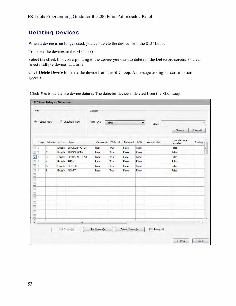
FS-Tools Programming Guide for the 200 Point Addressable Panel
53
Deleting Devices
When a device is no longer used, you can delete the device from the SLC Loop.
To delete the devices in the SLC loop
Select the check box corresponding to the device you want to delete in the Detectors screen. You can select multiple devices at a time.
Click Delete Device to delete the device from the SLC loop. A message asking for confirmation appears.
Click Yes to delete the device details. The detector device is deleted from the SLC Loop.

Detectors
54
Finding Devices
Using the Search option, you can find a device when there are multiple devices in the SLC loop. The Search option is available only with the Tabular View.
To find devices, select an option in Field Type. The available options are Custom Label, Status, Address, Type, Verification, Walktest, Presignal, PAS, Sounder Base Installed, Coding, Sounder Base Volume, Wireless, or Sounder Base Silenceable.
Select a Value from the drop-down list which corresponds to the selected Field Type.
Click Search. The search results are displayed in the Tabular View.
Click Show All to retrieve all the device records.
Click Save to Database to save the configuration in the FS-Tools database.
Click Next or click Modules in SLC Loop Setup in the left pane, to view the SLC Loop Setup -> Modules pane.
Click Prev to go back to the Secondary ANN-Bus configuration pane.
Device Address
In Device Address, specify the device address between 1 to 99.
To add only one device, click Single Device.
To add more than one device, click Multiple Devices and specify the number of devices you want to add in No. of devices. The device address will be the address for the first device. The next devices will have consecutive addresses.
You will get an error message if you select an invalid address.

FS-Tools Programming Guide for the 200 Point Addressable Panel
55
Detector Device Type
Select the Device Type from the drop-down box. Available types are:
Detector Type Action When Activated
Smoke Photo
User-Defined-1
Smoke Ion
User-Defined-2
Heat Detect
User-Defined-3
Smoke Duct-P
User-Defined-4
Photo w/Heat
User-Defined-5
Duct Superv
User-Defined-7
Photo-Super AR
User-Defined-8
ADAPT
User-Defined-10
Beam
User-Defined-11
Fire/CO
User-Defined-12
Fire Alarm
same as previous (Smoke Photo)
Fire Alarm
same as previous (Smoke Ion)
Fire Alarm
same as previous (Heat Detect)
Fire Alarm
same as previous (Smoke Duct-P)
Fire Alarm
same as previous (Photo w/Heat)
Supervisory, latching
same as previous (Duct Superv)
Supervisory, nonlatching (works only in LiteSpeed)
same as previous (Photo-Super AR)
Fire Alarm
same as previous (ADAPT)
Fire Alarm
same as previous (Beam)
response is programmable (Alarm, Supv, or None)
same as previous (Fire/CO)
To add a user defined device type, select USER-DEF-1 from the list, and click Edit Custom Type. Enter the new type label in the displayed window and click OK.
In Device Label, select the Adjective and the Noun which specify the device location. The adjective and noun are specific descriptors to identify the device location. To add a custom adjective/noun, select the Add New option from the adjective/noun list and specify the custom adjective/noun in the displayed window. Custom Label displays the selected Adjective and Noun.

Detectors
56
Detector Device Options
In Device Options, the Device Enabled option is selected by default (when you click Add Device). If this option is not selected, the detector is not polled by the control panel, which prevents the detector from reporting alarms and troubles to the panel. The control panel displays the device type and address of the disabled device and activates the Trouble and Disable LEDs.
To enable the Pre-Signal option for the device, click Pre-Signal Enabled. This option programs the detector to delay panel activation for a pre-programmed time delay of up to three minutes, while allowing for visual verification. The alarm relay and communicator respond to the initial alarm immediately. In addition, Zone 98 activates immediately and can be programmed to a control module, to activate a sounder or indicator designated for Pre-signal indication (do not use a Notification Appliance Circuit for this purpose).
To enable the PAS option for the device, click PAS Enabled. The PAS option programs the detector to delay panel activation (including alarm relay and communicator) for a period of fifteen seconds plus a programmable time of up to three minutes. Zone 97, however, activates immediately and can be used to connect a signaling device to indicate PAS activation (do not use a Notification Appliance Circuit for this purpose).
Note: For a device, you can enable the PAS option or the Pre-Signal option. You cannot enable both options together.
The Device Walktestable option is selected by default. The Walktest feature allows you to test the system devices without manually resetting the control panel after each device activation.
To enable the Alarm Verification option for the device, click Alarm Verification Enabled. Alarm verification is used to confirm that a smoke detector activation is a true alarm condition and not a false alarm.
You can map each device to five Zones. Enter the three digit number corresponding to the zone assigned to the device for Zone 1 to Zone 5. The factory default for an unprogrammed device is Z000 for a general alarm zone.
Enter the Additional Information about the detector being programmed. This information is displayed as part of the device label on the panel display.
Note: The Device Silenceable option is disabled for the detectors.

FS-Tools Programming Guide for the 200 Point Addressable Panel
57
Sounder Base Options
If the selected detector is installed in a Sounder Base, ensure that the Sounder Base Installed option checkbox is selected.
To enable the sounder base at this address, select the Sounder Base Enabled checkbox.
Coding: from the drop-down box, select the output type desired from the sounder base. The following options are available:
• Steady - a continuous output with no coding
• Temporal 3 - ½ Second On, ½ Second Off, ½ Second On, ½ Second Off, ½ Second On, 1½Seconds Off
• Temporal 4 - ½ Second On, ½ Second Off, ½ Second On, ½ Second Off, ½ Second On, ½Second Off, ½ Second On, 1½ Seconds Off
• March Time - 120 ppm (pulse-per-minute) output
Volume: from the drop-down box, select the sounder base output volume. Available settings are Low, Medium, and High.
Zones: You can map each Sounder Base to five Zones. Enter the three digit number corresponding to the zone assigned to the device for Zone 1 to Zone 5. The factory default for an unprogrammed device is Z000 for a general alarm zone.
Wireless Option
If the selected device is a wireless device, part of the SWIFT® Wireless System, select the Wireless checkbox.
For more information on the SWIFT Wireless system, refer to Document number #LS10036-000FL-E on www.firelite.com.

Modules
58
Modules
From the detectors screen, you can:
• Add a new addressable module to the SLC loop.
• View the added modules in a tabular or graphical form
• Edit the programming for an existing module.
• Delete an existing module from the loop.
• Search for modules in a zone.

FS-Tools Programming Guide for the 200 Point Addressable Panel
59
Adding Devices
From the bottom of the detector screen, select the Add Device(s) button. The following screen appears. See the following pages to learn more.
Click OK when finished and the device(s) will appear on the module screen.

Modules
60
Viewing Devices
There are two ways the devices can be viewed. There is a tabular view which outlines the device information in a table view.
The graphical view offers a pictorial view of the devices on the loop.

FS-Tools Programming Guide for the 200 Point Addressable Panel
61
Editing Devices
Using the Edit Devices option, you can edit the device type, device options, and change the zone mapping.
Select the check box corresponding to the device you want to edit in the Modules screen. You can select only one device at a time.
Click Edit Device(s) to edit the device information. The Edit dialog box appears.
Update the device information such as Device Type, Device Label, Device Options, Zone assignments, and Wireless participation.
Click OK. The device information is updated in SLC loop setup.
Note: You cannot modify the device address using the Edit Device option.

Modules
62
Deleting Devices
When a device is no longer used, you can delete the device from the SLC Loop.
To delete the devices in the SLC loop
Select the check box corresponding to the device you want to delete in the Modules screen. You can select multiple devices at a time.
Click Delete Device to delete the device from the SLC loop. A message asking for confirmation appears.
Click Yes to delete the device details. The module device is deleted from the SLC Loop.

FS-Tools Programming Guide for the 200 Point Addressable Panel
63
Finding Devices
Using the Search option, you can find a device when there are multiple devices in the SLC loop. The Search option is available only with the Tabular View.
To find devices, select an option in Field Type. The available options are Custom Label, Status, Address, Type, Silenceable, Walktest, Presignal, PAS, Wireless, Control Module Delay Timer Enabled, and MNS Override.
Select a Value from the drop-down list which corresponds to the selected Field Type.
Click Search. The search results are displayed in the Tabular View.
Click Show All to retrieve all the device records.
Click Save to Database to save the configuration in the FS-Tools database.
Click Save as Template to save the configuration as a template. The saved template can be used for configuring other fire panels using the same computer or laptop. Type the new Template Name in the save as dialog box, then click Save, to save the fire panel configuration as a template.
Click Next or click Verify Setup in the left pane, to check input/output mapping.
Click Prev to go back to the Detectors pane.
Device Address
In Device Address, specify the device address between 1 to 99.
To add only one device, click Single Device.
To add more than one device, click Multiple Devices and specify the number of devices you want to add in No. of devices. The device address will be the address for the first device. The next devices will have consecutive addresses.
You will get an error message if you select an invalid address.

Modules
64
Module Device Type
Device types tell the panel what function each module will perform. Separate type codes are available for Monitor Modules and Control Modules.
Monitor Module Types
Select the Monitor Device Type from the drop-down box. Available types are:
Monitor Type Action When Activated Pull Station
User-Defined-1
Waterflow
User-Defined-2
Monitor
User-Defined-3
Future
Future
Smoke-Conventional
User-Defined-5
Heat-Conventional
User-Defined-6
Medic-Alert
User-Defined-7
Hazard-Alert
User-Defined-8
Tornado-Alert
User-Defined-9
Phone
User-Defined-10
Tamper
User-Defined-11
Supervisory
Fire Alarm
same as previous (Pull Station)
Fire Alarm Delayed
same as previous (Waterflow)
Fire Alarm
same as previous (Monitor)
not used
not used
Fire Alarm
same as previous (Smoke-Conventional)
Fire Alarm
same as previous (Heat-Conventional)
General Purpose Signaling, latching
same as previous (Medic-Alert)
General Purpose Signaling, latching
same as previous (Hazard-Alert)
General Purpose Signaling, latching
same as previous (Tornado-Alert)
Active Phone (LCD display only)
same as previous (Phone)
Supervisory, nonlatching (tracking)
same as previous (Tamper)
Supervisory, latching

FS-Tools Programming Guide for the 200 Point Addressable Panel
65
User-Defined-12
Supervisory-AR
User-Defined-13
HVAC OVRRIDE
Power-Monitor
User-Defined-14
Trouble-Monitor
User-Defined-15
Process-Monitor
User-Defined 16
Process-Monitor-AR
User-Defined 17
MNS Event
User-Defined 18
Ack-Switch
Sil Switch
Reset Switch
Drill Switch
PAS Bypass HVAC
RESTART Drill
Switch AR
Wireless Gateway
same as previous (Supervisory)
Supervisory, nonlatching (tracking)
same as previous (Supervisory-AR)
Switch Supervisory, nonlatching (tracking)
Power Fault
same as previous (Power Monitor)
Trouble
same as previous (Trouble Monitor)
General Purpose Signaling, latching
same as previous (Process-Monitor)
General Purpose Signaling, nonlatching (tracking)
same as previous (Process-Monitor-AR)
Allows the Mass Notification System to override FACP programming and turn off designated active outputs
same as previous (MNS Event)
Acts like panel Acknowledge Key
Acts like panel Silence Key
Acts like panel Reset Key
Acts like panel Drill Key
PAS Disable
Switch
Acts like panel Drill Key, nonlatching (tracking)
Reports wireless gateway troubles to the FACP (Using this type code replaces the need for a remote annunciator/display driver on the SWIFT network.)
To add a user defined device type, select USER-DEF-1 from the list, and click Edit Custom Type. Enter the new type label in the displayed window and click OK.
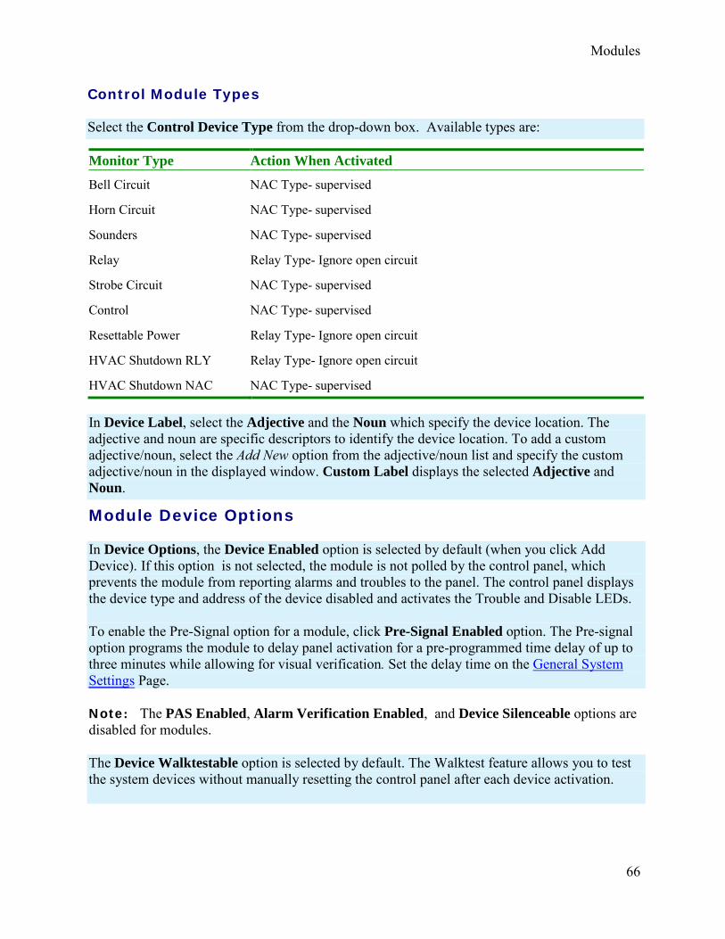
Modules
66
Control Module Types
Select the Control Device Type from the drop-down box. Available types are:
Monitor Type Action When Activated
NAC Type- supervised
NAC Type- supervised
NAC Type- supervised
Relay Type- Ignore open circuit
NAC Type- supervised
NAC Type- supervised
Bell Circuit
Horn Circuit
Sounders
Relay
Strobe Circuit
Control
Resettable Power
HVAC Shutdown RLY
HVAC Shutdown NAC
Relay Type- Ignore open circuit
Relay Type- Ignore open circuit
NAC Type- supervised
In Device Label, select the Adjective and the Noun which specify the device location. The adjective and noun are specific descriptors to identify the device location. To add a custom adjective/noun, select the Add New option from the adjective/noun list and specify the custom adjective/noun in the displayed window. Custom Label displays the selected Adjective and Noun.
Module Device Options
In Device Options, the Device Enabled option is selected by default (when you click Add Device). If this option is not selected, the module is not polled by the control panel, which prevents the module from reporting alarms and troubles to the panel. The control panel displays the device type and address of the device disabled and activates the Trouble and Disable LEDs.
To enable the Pre-Signal option for a module, click Pre-Signal Enabled option. The Pre-signal option programs the module to delay panel activation for a pre-programmed time delay of up to three minutes while allowing for visual verification. Set the delay time on the General System Settings Page.
Note: The PAS Enabled, Alarm Verification Enabled, and Device Silenceable options are disabled for modules.
The Device Walktestable option is selected by default. The Walktest feature allows you to test the system devices without manually resetting the control panel after each device activation.

FS-Tools Programming Guide for the 200 Point Addressable Panel
67
The Delay Timer Enabled feature is only applicable to Control Modules. When enabled, this timer delays activation of the selected control module after being triggered by an alarm condition. Delay time varies from 0-180 seconds. Set the delay time on the General System Settings Page.
You can map each device to five Zones. Enter the three digit number corresponding to the zone assigned to the device for Zone 1 to Zone 5. The factory default for an unprogrammed device is Z000 for a general alarm zone.
Enter the Additional Information about the detector being programmed. This information is displayed as part of the device label on the panel display.
Wireless Option
If the selected device is a wireless device, part of the SWIFT® Wireless System, select the Wireless checkbox.
For more information on the SWIFT Wireless system, refer to Document number #LS10036-000FL-E on www.firelite.com.
Verify Setup The Verify Setup feature checks to see whether each input device is programmed to at least one output device and vice versa. This feature verifies the loop configuration and displays a warning message if there is a mismatch.
Click Verify Setup to check the mapping of the input and output devices.
If there is a proper mapping between each input device and output device, a message appears to indicate there are no warnings in verification.
A warning is displayed listing if all the detector devices and monitor modules are not connected to an output/input device.

Verify Setup
68
Click Print if you want to create a PDF file of the verification errors.
Click Next or click Simulation -> Tabular View in the left pane, to view the Simulation screen. Click
Prev to go back to the SLC Loop Setup -> Modules pane

FS-Tools Programming Guide for the 200 Point Addressable Panel
Simulation The Simulation feature allows you to view the zone correlations for the installed devices to confirm the programming. Using this feature, you can find any mismatch in the zone correlations not detected through the Verify Setup option. This feature is available with both the tabular and graphical views.
Tabular View To perform a simulation in a tabular view:
Click Start Simulation.
Click the address of an input device to view the output correlations or click the address of an output device to view the input correlations.
69
The Input devices are denoted by << in the displayed Results.

Simulation
70
The Output devices are denoted by >> in the displayed Results.
Click Refresh to refresh the displayed results when you select another detector.
Click Stop Simulation to stop the simulation.
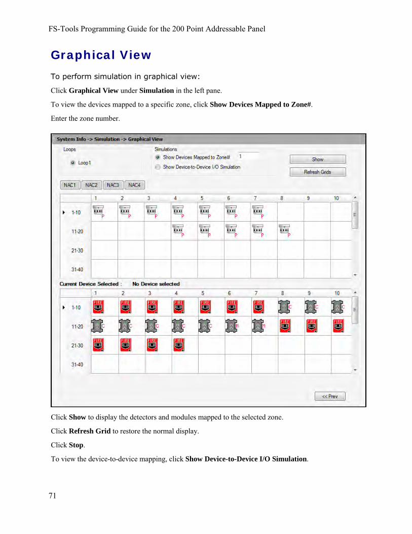
FS-Tools Programming Guide for the 200 Point Addressable Panel
71
Graphical View To perform simulation in graphical view:
Click Graphical View under Simulation in the left pane.
To view the devices mapped to a specific zone, click Show Devices Mapped to Zone#.
Enter the zone number.
Click Show to display the detectors and modules mapped to the selected zone.
Click Refresh Grid to restore the normal display.
Click Stop.
To view the device-to-device mapping, click Show Device-to-Device I/O Simulation.

Configuring the Fire Panel
72
Click Show to display the output devices mapped to a selected input device.
Upload Information The uploaded information displays all the configuration information retrieved from the fire panel to the computer, using FS-Tools. In addition to the configuration information, the following data can be uploaded from the fire panel.
Walktest Data
History Data
System Status Data
The uploaded information from the fire panel helps to monitor troubles, alarms, and other fire panel events.
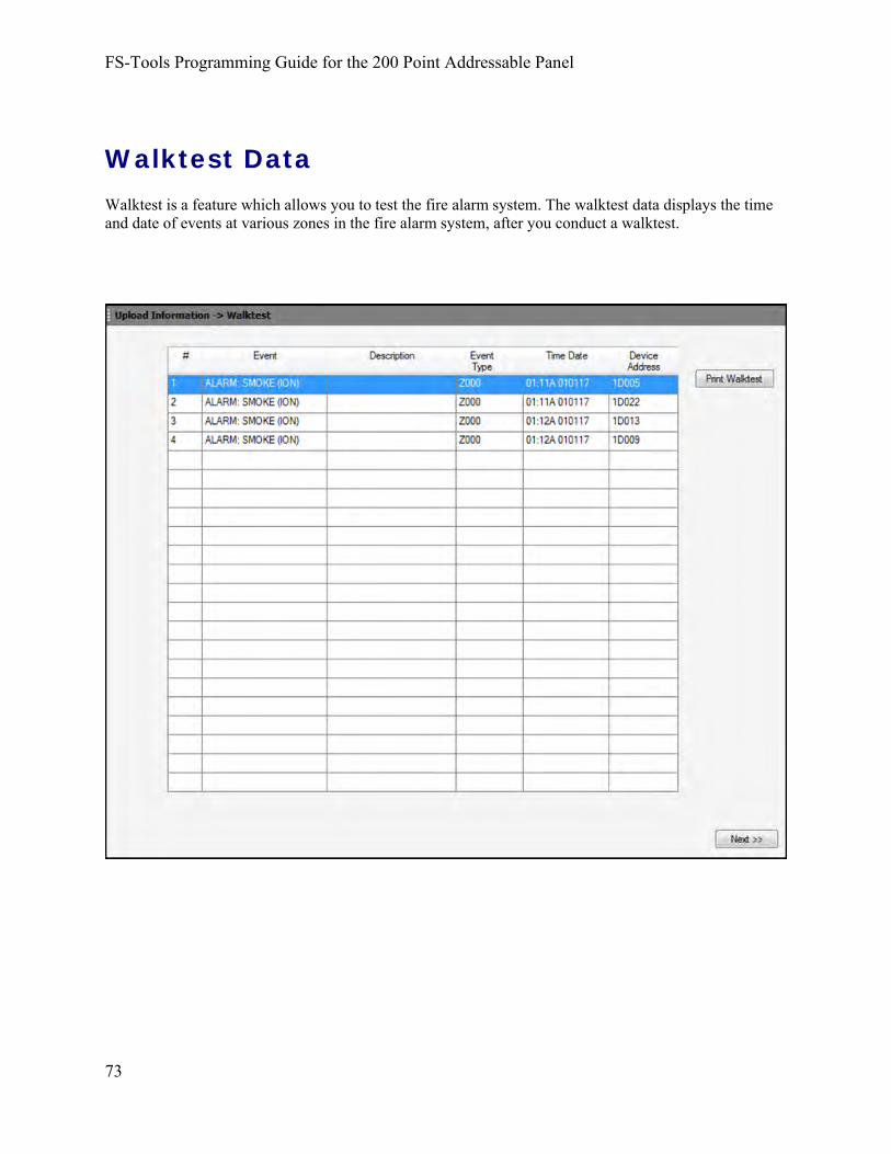
FS-Tools Programming Guide for the 200 Point Addressable Panel
73
Walktest Data Walktest is a feature which allows you to test the fire alarm system. The walktest data displays the time and date of events at various zones in the fire alarm system, after you conduct a walktest.

Configuring the Fire Panel
74
History Data The history data lists all the events and event types such as alarms, troubles, activations, and other information with the date and time of occurrence.

FS-Tools Programming Guide for the 200 Point Addressable Panel
75
System Status Data The system status data displays the detector sensitivity data and LED and piezo status of the panel.

76
File Menu Changing Download Password To download the configuration data to the fire panel, you must connect the computer to the fire panel. In FS-Tools, you can change the download password for downloading the configuration data to the fire panel, only if you have administrator rights.
Note: You must add at least one customer record before changing the download password.
In the File menu in the initial customer screen, click Change Download Password. The Change Password window appears.
Type the Old Password.
Type the New Password, and then retype the password in Confirm Password.
Click OK. The download password is changed.

77
Template Menu Delete a Template A configuration template can be deleted when it is no longer needed.
To delete a template, choose Template > Delete Template in the initial customer screen in FS-Tools. The Delete Template dialog box appears.
Select the template from the list displayed in Existing Templates.
Click Delete Template. This deletes the configuration template.
Note: The factory default template cannot be deleted.

78
Tools Menu Compare Configuration The Compare Configuration option shows the differences in fire panel configurations for two different customers or two different configurations for the same customer.
To compare two configurations, click Tools > Compare Configuration in the initial customer screen in FS-Tools. The Compare Configuration dialog box appears.
Select Customer1 and Customer2.
Select the Configuration for Customer1 and Customer2.
Click Compare. The Compare Results dialog box displays the compared System Configuration data for the two customers.
Using the Compare Results dialog box, you can also perform the following.
• Click Expand All for an expanded view of all the configuration data in SystemConfiguration tab.
• Click Collapse All for an collapsed view of all the configuration data in SystemConfiguration tab.
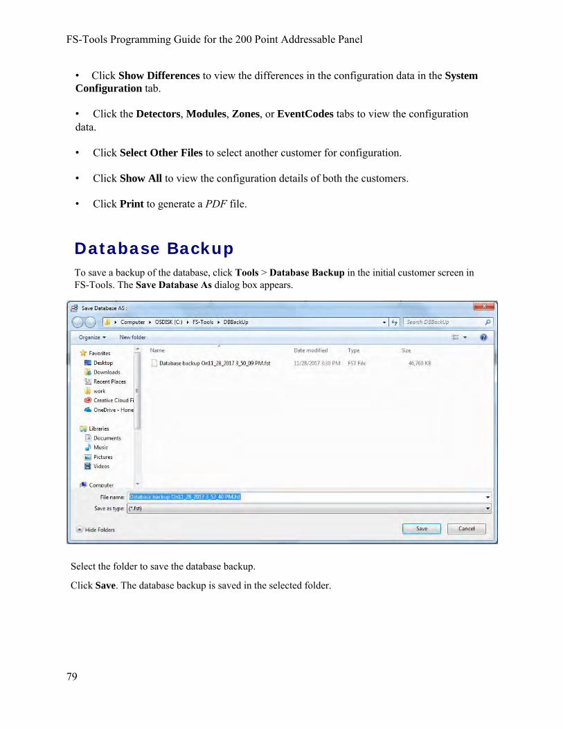
• Click Show Differences to view the differences in the configuration data in the System Configuration tab.
• Click the Detectors, Modules, Zones, or EventCodes tabs to view the configuration data.
• Click Select Other Files to select another customer for configuration.
• Click Show All to view the configuration details of both the customers.
• Click Print to generate a PDF file.
Database Backup To save a backup of the database, click Tools > Database Backup in the initial customer screen in FS-Tools. The Save Database As dialog box appears.
FS-Tools Programming Guide for the 200 Point Addressable Panel
79
Select the folder to save the database backup.
Click Save. The database backup is saved in the selected folder.

Tools Menu
80
Restore Backup There can be situations where the current working database encounters problems. In such cases you can restore a backup of the working database. You can restore the database that was last backed up to ensure minimum data loss.
To restore the database, click Tools > Restore Backup in the initial customer screen in FS-Tools. The File Type dialog box appears.
Select the database file to restore and click Open.
A message informing you about the application being closed is displayed.
Click OK. FS-Tools will automatically close and need to be restarted.

FS-Tools Programming Guide for the 200 Point Addressable Panel
81
Export a Configuration The export configuration option is used when the same configuration needs to be used for configuring a fire panel, in another location with a different computer. The exported configuration can be saved onto a floppy disk or a CD-ROM and reused.
You can export the configuration in two ways:
• Export To Excel
• Export To Disk
Export to Excel To export the configuration to an excel sheet, choose Tools > Export > Export To Excel in the initial customer screen in FS-Tools. The Export Selected Configuration As dialog box appears.
Select the folder in which the exported configuration will be saved.
Click Save. A message indicating that the details are successful exported is displayed.
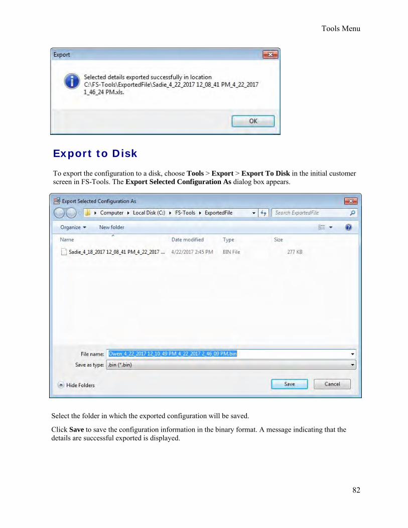
Tools Menu
82
Export to Disk
To export the configuration to a disk, choose Tools > Export > Export To Disk in the initial customer screen in FS-Tools. The Export Selected Configuration As dialog box appears.
Select the folder in which the exported configuration will be saved.
Click Save to save the configuration information in the binary format. A message indicating that the details are successful exported is displayed.

83
FS-Tools Programming Guide for the 200 Point Addressable Panel
Import a Configuration You can import configuration details from the panel to FS-Tools.
To import a configuration, choose Tools > Import in the initial customer screen in FS-Tools. The Import Configuration From dialog box appears.
Select a configuration file and then click Open. The configuration details are imported in the binary format. A message, prompting you to save the configuration details to the database is displayed.
Click Yes to save the details to the database.

Tools Menu
84
Import All Configurations Using FS-Tools, You can import and update all the configuration details from to the FS-Tools database without modifying the existing information.
To import all the configurations, choose Tools > Import All from the initial customer details window in FS-Tools. The Import Database from dialog box appears.
Select the configuration files, and then click Open. The configuration details are updated. After updating the configuration details, a message appears, prompting you to restart the application, to view the changes.
Click OK.

FS-Tools Programming Guide for the 200 Point Addressable Panel
85
Get Write Access
Modifying Customer Details
You can modify or view the customer details from the database server. To modify, you need to obtain write permission. To view, a read-only permission is sufficient.
To obtain write permission:
Select a Customer.
Choose Tools > Get Write Access in the initial customer screen in FS-Tools. A message, indicating the status for obtaining the write permission, appears. If the customer details are currently modified by another user, you might get only a read-only access. Try again after some time to obtain the write access.
After obtaining the write permission, click Configure in the initial customer screen in FS-Tools, to modify the configuration settings.
Note: If you click Tools->Get Write Access on a computer running Windows ®7/ Windows ® Vista/Windows ® XP SP2, the networked computer does not display any message. This is applicable only to Custom Setup.
To view the configuration details:
Select and double-click a Customer. A message asking for confirmation appears.
Click OK to view the customer details in read only mode.

Tools Menu
86
Run from Database Using FS-Tools, you can connect to the database installed on your computer (client database or to the database installed on a remote computer (server database.
Note: If you have installed the client and the server on the same computer, then your computer acts as both client and server.
To Connect to the Server Database
Choose Tools > Run from Database > Server Machine from the initial customer details window in FS-Tools. The Server Machine dialog box appears.
In the Enter the IP Address or Machine Name of the Server text box, type the IP address or the machine name of the computer on which you have installed the database.
Click OK. A message informing you about the application being restarted, is displayed.
Click OK. The details of the server database are listed in the initial customer window in FS-Tools.

87
FS-Tools Programming Guide for the 200 Point Addressable Panel
To Connect to the Client Database
Choose Tools > Run from Database > Client Machine from the initial customer details window in FS-Tools. A message appears, informing you about the path where you have installed the client database.
Click OK to restore the client database.
Last Configuration Date Using FS-Tools, you can view the details of a particular customer such as configuration date, when there are multiple customers with the same name, panel type, etc.
To view the configuration date, select the Customer.
Click Tools > Last Configuration Date from the initial customer details window in FS-Tools. The Last Configuration Date dialog box appears, displaying the details of the particular customer.
Click OK.

Tools Menu
88
Upload/Download Menu Upload/Download Configuration Data The configuration process is completed only when you download the saved configuration to the fire panel. Using the Upload/Download option in FS-Tools, you can:
• Download saved configuration and other panel settings to the fire panel.
• Upload Configuration Data, History Data, Walktest Data, Troubleshoot Data, System Status,and Point Status information from the fire panel to the computer.
• View all the uploaded data from the fire panel to monitor the fire alarm system and identifytroubles, alarms, and other events.
Ensure the fire panel remains in the ‘System Normal’ state when you download or upload data to and from the fire panel. You can connect the computer to the fire panel using a USB port, or ethernet connection.
Upload/Download
Download Configuration Data to the FACP
Using the Download to Panel option, you can download the Point Programming, Communicator, Event Codes, Zones, General System Settings, ANN-Bus, Date and Time configuration data to the fire panel. When you download data for the first time, ensure that all the configuration data are downloaded to the fire panel.
To download the configuration information to the fire panel, click Upload/Download > Upload/Download from the initial customer details window in FS-Tools. The upload/download window opens.
Ensure that the FACP is available to accept downloads by pressing Menu on the FACP keypad. Then select option 3=FSTOOL UP/DOWNLOAD. Otherwise, configuration download requests will be denied at the panel.

89
1. Select the Communication Mode from the drop-down menu. FS-Tools can connect directlywith the FACP using a USB cable or remotely with an Ethernet connection to the IPOTS-COMcommunicator.
2. In the Download to Panel section of the window, you can select individual options todownload (Point Programming, DACT, Event Codes, Zones, System Programming, Options,ANN-Bus, and Date and Time configuration data) or select all configuration data to send allinformation to download to the fire panel.
3. Click Download to panel.

Upload/Download Menu
90
4. Click Clear Display to clear the display of the status information in PC Panel Communication Status.
When the download is complete, the status that the configuration data is saved in the database is displayed in PC Panel Communication Status.
5. Click Close to close the Upload/Download dialog box after the upload/download process is completed.
If after clicking Download to Panel, the panel version does not match the FS-Tools version on the computer, a message asking you to view the difference in features appears.
Click Yes. The Difference in Upload/Download window appears.

91
FS-Tools Programming Guide for the 200 Point Addressable Panel
In the System Configuration tab, you can view the information such as name of the feature, the value assigned to the feature in FS-Tools, and the values downloaded to the panel. Click Print to generate a PDF file.
Note: If the feature configured in FS-Tools is not present in the panel, a message is displayed corresponding to the value in FS-Tools.

Upload/Download Menu
92
In the Device Types tab, you can view the information such as loop, address, name of the device, the value assigned to the feature in FS-Tools, and values downloaded to the panel. Click Print to generate a PDF file.

FS-Tools Programming Guide for the 200 Point Addressable Panel
93
In the Event Codes tab, you can view the information such as values configured to upload or download, details on central station, event codes description, active value, and restoral. Click Print to generate a PDF file.

Upload/Download Menu
94
Upload Configuration Data from the FACP
Using the Upload from Panel option, you can view the System Status data, History data, Walktest data, Date and Time data from the fire panel. The uploaded information is useful for monitoring the fire alarm system status and identifying troubles, alarms, and other events. When you upload information for the first time, ensure that all the information is uploaded from the fire panel.
To upload information from the fire panel, click Upload/Download > Upload/Download from the initial customer details window in FS-Tools. The upload/download window opens.

FS-Tools Programming Guide for the 200 Point Addressable Panel
95
1. Select the Communication Mode from the drop-down menu. FS-Tools can connect directlywith the FACP using a USB cable or remotely with an Ethernet connection to the IPOTS-COMcommunicator.
2. In the Upload from Panel section of the window, you can select individual options to upload(System Status, History, Walktest, or Date and Time) or select all Configuration Data to uploadall information from the fire panel.
3. Click Upload from Panel.
4. A message appears to indicate the configuration data is saved in FS-Tools. Click OK.
5. Click View Upload Files to view all the uploaded information from the fire panel such ashistory data, system status data, and walktest data saved in the FS-Tools database. All theuploaded information is displayed in the PC Panel Communication Status window.
6. Click Close to close the Upload/Download dialog box after the upload/download process iscompleted.

Upload/Download Menu
96
Connection Settings
The connection settings option displays the details of the USB device, Modem or Serial port attached to the computer for communication with the fire panel. The modem can be a USB modem or a serial modem. For a USB modem, the modem vendor provides the driver that must be installed before launching FS-Tools.
USB Connection Settings
To view the USB device settings:
1. Select the customer for whom the connection settings needs to be viewed.
2. Click Upload/Download > Connection Settings in the initial customer screen in FS-Tools.The Connection Settings dialog box appears.
3. In Communication Mode list, select the USB option. The information to view/modify theUSB settings appears in the Connection Settings dialog box
4. Click Auto Detect to detect any USB device attached to the system. The details of theattached USB Device (if any) are displayed in USB Device Attached to System.

FS-Tools Programming Guide for the 200 Point Addressable Panel
97
5. Click Clear to clear the displayed data if there are multiple lines of data to scroll through inUSB Device Attached to System.
6. Click Close to close the dialog box after you verify the connection settings between thecomputer and the fire panel.
Thumb Drive Upload/Download
Transfer Database To Flash Drive
To transfer the panel database to a Flash Drive:
1. Insert a Flash Drive into the USB port of your PC.
2. Select the customer for whom the panel settings are to be downloaded to a USB flash drive.
3. Click Upload/Download > Thumb Drive Upload/Download > Transfer Configuration toThumb/USB/Flash Drive in the initial customer screen in FS-Tools.
4. Select the USB port with the Flash Drive from the selection box and click Save.

Upload/Download Menu
98
If a Flash Drive is not detected by FS-Tools, you will get a warning message.
FS-Tools will save the program database on the Flash Drive as "FS_200.cfg".
Note: Before loading the new database into the fire panel, the existing database will be saved as file, "FS_200_bak.cfg" on the USB flash drive. Only one new and one saved database can reside on the USB flash drive at a given time.
A confirmation dialog box displays when the database is successfully transferred to the USB drive.

FS-Tools Programming Guide for the 200 Point Addressable Panel
99
Transfer Database From Flash Drive
To transfer the panel database from a flash drive to FS-Tools,
1. Insert a Flash Drive into the USB port of your PC.
2. Select the customer from the main screen to where you want to save
3. Click Upload/Download > Thumb Drive Upload/Download > Transfer ConfigurationDatabase From Thumb/USB/Flash Drive in the initial customer screen in FS-Tools. The USBSelection screen displays.
4. Select the drive with the desired USB stick and click Read.
5. Navigate to the configuration file saved to the USB drive from the FACP. The file will have a.bak extension.
6. Select file and click Open.
7. The confirmation dialog box displays and the panel configuration is saved to the database.
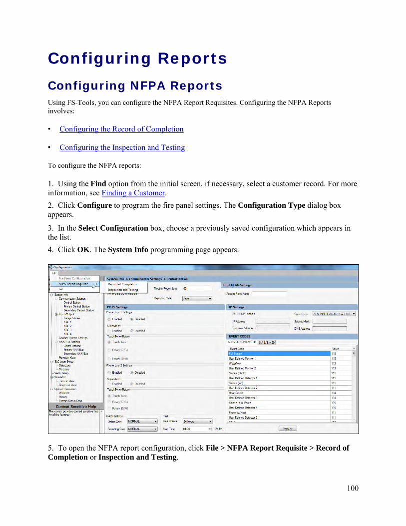
100
Configuring Reports Configuring NFPA Reports Using FS-Tools, you can configure the NFPA Report Requisites. Configuring the NFPA Reports involves:
• Configuring the Record of Completion
• Configuring the Inspection and Testing
To configure the NFPA reports:
1. Using the Find option from the initial screen, if necessary, select a customer record. For more information, see Finding a Customer.2. Click Configure to program the fire panel settings. The Configuration Type dialog box appears.
3. In the Select Configuration box, choose a previously saved configuration which appears in the list.4. Click OK. The System Info programming page appears.
5. To open the NFPA report configuration, click File > NFPA Report Requisite > Record of Completion or Inspection and Testing.

101
FS-Tools Programming Guide for the 200 Point Addressable Panel
Record of Completion In FS-Tools, configuring the Record of Completion involves the following steps.
1. Configure the Protected Site Information
2. Configure the Fire Alarm System Information
3. Configure the Type of Fire Alarm System
4. Configure the System Software
5. Configure the Signaling Line Circuits
a. Manual and Automatic Initiating Device
b. Supervisory Signal- Initiating Devices and Circuits
6. Configure the Annunciators
7. Configure the Alarm Notification Devices and Circuits
8. Configure the System Power Supply
9. Configure the Record of system installation and System Operation
10. Obtain the Certifications and Approvals

Configuring Reports
102
Protected Site Information
To configure the Protected Site Information:
1. Under Site Information, type the Site Name, Address, Description of Property andOccupancy Type of the site.
2. Under Property Representative, type the Name of the Property Representative, Address,Phone, FAX and E-mail of the site representative.
3. Under Authority having jurisdiction over this property, type the Name, Address, Phone, FAX and E-mail of the AHJ.
Click Save to Database to save the Record of Completion report requisites to database. Click Next or click Fire Alarm System Information in the left pane, to view the Fire Alarm System Information configuration pane.
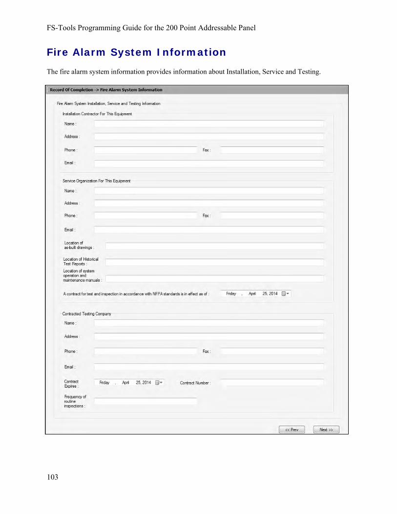
FS-Tools Programming Guide for the 200 Point Addressable Panel
103
Fire Alarm System Information
The fire alarm system information provides information about Installation, Service and Testing.

Configuring Reports
104
To configure the Fire Alarm System Information:
1. Type the Name, Address, Phone, FAX and E-mail of the contractor under InstallationContractor For This Equipment.
2. Type the Name, Address, Phone, FAX, E-mail, Location of as-built drawings, Locationof Historical Test Reports and Location of system operation and maintenance manuals ofthe service organization, under Service Organization of this equipment.
3. Select the effective date for a contract of test and inspection in accordance with NFPAstandards from the drop-down box.
4. Type the Name, Address, Phone, FAX, E-mail, Contact Number and Frequency ofroutine inspections of the testing company under Contracted Testing Company.
5. Select the Contract Expires date from the drop-down box.
Click Next or click Type of Fire Alarm System in the left pane, to configure the type of fire alarm system.
Click Prev to go back to the Protected Site Information.
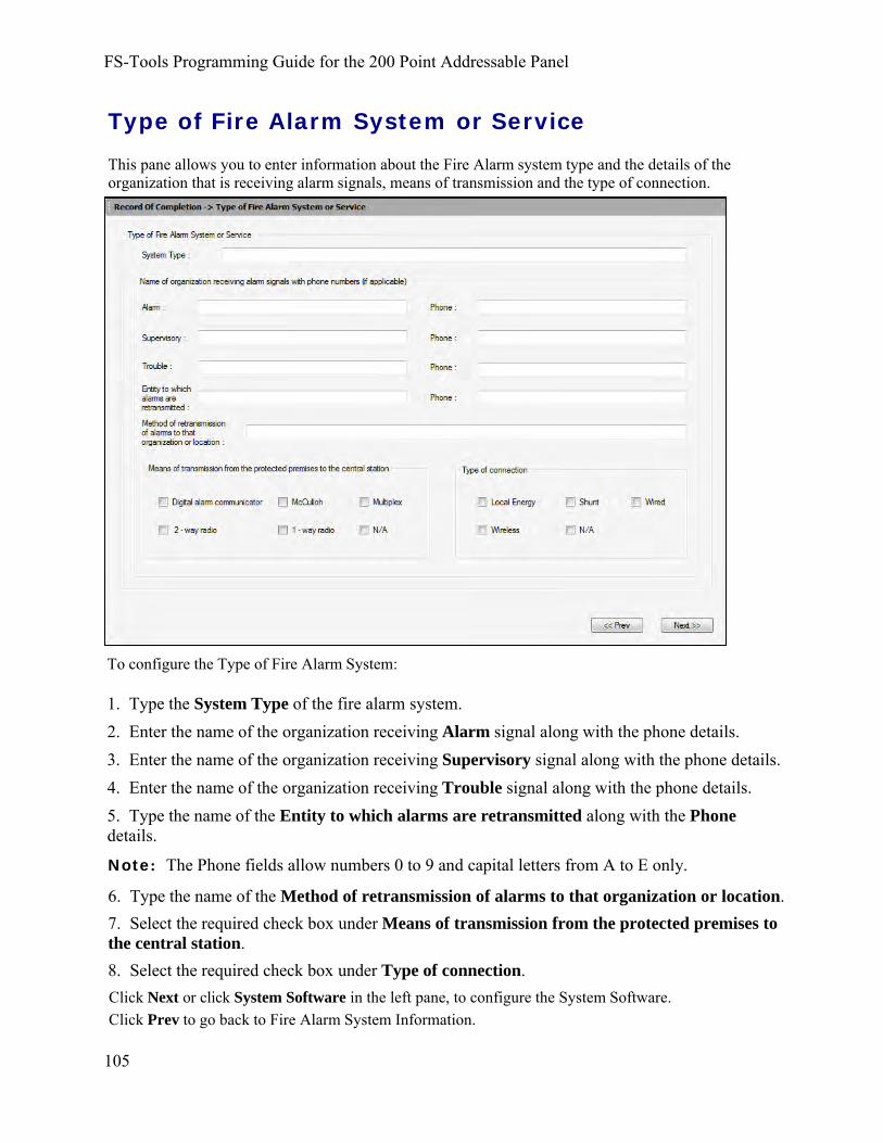
FS-Tools Programming Guide for the 200 Point Addressable Panel
105
Type of Fire Alarm System or Service
This pane allows you to enter information about the Fire Alarm system type and the details of the organization that is receiving alarm signals, means of transmission and the type of connection.
To configure the Type of Fire Alarm System:
1. Type the System Type of the fire alarm system.2. Enter the name of the organization receiving Alarm signal along with the phone details.3. Enter the name of the organization receiving Supervisory signal along with the phone details.4. Enter the name of the organization receiving Trouble signal along with the phone details.5. Type the name of the Entity to which alarms are retransmitted along with the Phone details.
Note: The Phone fields allow numbers 0 to 9 and capital letters from A to E only.
6. Type the name of the Method of retransmission of alarms to that organization or location.7. Select the required check box under Means of transmission from the protected premises to the central station.8. Select the required check box under Type of connection. Click Next or click System Software in the left pane, to configure the System Software. Click Prev to go back to Fire Alarm System Information.

Configuring Reports
106
System Software
This pane allows you to configure the Operating system revision level and date.
1. Type the Operating System (executive) software revision level of the alarm software.
2. Select the Site-specific software revision date.
3. Type the name of the person in Revision completed by.
Click Next or click Signaling Line Circuits in the left pane, to configure the Signaling Line Circuit.
Click Prev to go back to Type of Fire Alarm System.

107
FS-Tools Programming Guide for the 200 Point Addressable Panel
Signaling Line Circuit
Manual and Automatic Initiating Devices and Circuits
In this pane you can configure the Alarm Initiating Devices and Circuits, Manual Initiating Devices and Automatic Initiating Devices. It also allows you to configure the Supervisory Signal –Initiating Devices and Circuits.

Configuring Reports
108
To configure the Signaling Line Circuits:
1. Enter the total number of devices installed on the SLC in the Quantity box.
2. Select the wiring Style from the drop-down box.
3. Enter the wiring Class (Class A or Class B).
4. In Alarm Initiating devices and circuits, repeat the steps 1 through 3 of Signaling Line Circuits to fill the data.
Note: The number of detectors and input modules here depends on the number of devices mapped in the FACP. The maximum number of devices is 198, 99 detectors and 99 modules.
5. Under Manual Initiating Devices –Manual Pull Stations, type the Number of manual pull stations added to the FACP configuration and click the required Type of devices check box.
6. Under Automatic Initiating Devices – Duct Smoke Detectors, type the Number of Duct Smoke Detectors added in FACP configuration and Type of Coverage.
7. Select the required Type of devices and Type of smoke detector sensing technology check boxes.
8. Under Automatic Initiating Devices – Heat Detectors, type the Number of Heat Detectors added in FACP configuration and select the required checkboxes for Type of Coverage and Type of Devices.
9. Under Automatic Initiating Devices – Sprinkler Waterflow Detectors, type the Number of Waterflow Detectors added in FACP configuration and click the required checkboxes for Type of devices.
10.Under Automatic Initiating Devices – Area Smoke Detectors, type the Number of area Smoke Detectors added in FACP configuration and click the required checkboxes for Type of Coverage, Type of Devices and Type of smoke detector sensing technology.
11.Under Automatic Initiating Devices – Alarm Verification, type the Number of devices subject to alarm verification.
12.Click Enabled if alarm verification on this system is enabled and type the number of seconds in the Set for.
Note: This radio button is enabled if all the detectors on this system are in alarm verification otherwise it is disabled.
Click Next or click Supervisory Signal in the left pane to configure the Supervisory Signal- Initiating Devices and Circuits.
Click Prev to go back to System Software.

109
FS-Tools Programming Guide for the 200 Point Addressable Panel
Signaling Line Circuit
Supervisory Signal
The Supervisory Signal pane allows you to configure the Initiating Devices and Circuits namely Fire pump, Sprinkler System, and Engine Driven Generators.

Configuring Reports
110
To configure the Supervisory Signal:
1. Under Supervisory Signal – Initiating Devices and Circuits – Fire Pump, select therequired check box for Type of fire pump.
2. Click the required check box for Type of fire pump supervisory devices.
3. Click the required check box for Fire Pump Functions Supervised.
4. Type the Other supervisory signals information in the box provided.
5. Under Supervisory Signal – Initiating Devices and Circuits – Sprinkler System, type theNumber of valve supervisory switches.
6. Click the required check box for Type of devices.
7. Under Supervisory Signal – Initiating Devices and Circuits – Engine-Driven Generator,click the required check boxes for Type of generator supervisory devices.
8. Type the Other supervisory signals information in the box provided.
Click Next or click Annunciators in the left pane to configure the annunciators.
Click Prev to go back to Signaling Line Circuit.

Annunciators
The Annunciators pane allows you to configure the Local/Remote, Type and Location for the Annunciators.
FS-Tools Programming Guide for the 200 Point Addressable Panel
111
To configure the Annunciators:
1. Under Local/Remote select local or remote for each Annunciator address.
2. Select the required type (Addressable, Directory, Graphic, N/A, Not Installed, ANN-80, ANN-I/O, ANN-S/PG, ANN-(R)LED, ANN-RLY, ANN-ACC, ANN-ECC or ANN-100 ) for eachAnnunciator address.
3. Type the Location of each annunciator.
Click Next or click Alarm Notification Devices in the left pane, to configure the alarm notification devices and circuits.
Click Prev to go back to Supervisory Signal.

Configuring Reports
112
Alarm Notification Devices and Circuits
The Alarm Notification devices and circuits pane allows you to configure the parameters namely Emergency Voice Alarm Service, Telephone jacks, Types and Quantities of Non-voice Notification Appliances Installed and Non-voice Audible System.

FS-Tools Programming Guide for the 200 Point Addressable Panel
113
To configure the Alarm Notification Devices and Circuits:
1. Under Emergency Voice Alarm Service, enter the Number of single and multiple voicealarm channels.
2. Enter the Number of Speakers and Number of Speaker Zones.
3. Under Telephone jacks, enter the Number of telephone jacks installed.
4. Enter the Number of telephone handsets store on site.
5. Click the required check box in Type of telephone system installed.
6. Under the Non-Voice Audible System option, enter the Quantity for the SLC Loop 1 andNAC.
7. Select the required Style for the NAC .
8. Type the Class for NAC .
9. Enter the number of Bells required under NAC, With visual devices in the boxes provided.
Note: Under Types and Quantities of Non-voice Notification Appliances Installed, the number of Bell devices displayed is based on the number of Bell devices added in Output modules of the fire panel configuration.
10. Enter the number of Horns required under NAC, With visual devices in the boxesprovided
Note: The number of Horn devices displayed is based on the number of Horn devices added in Output modules of the fire panel configuration.
11. Enter the number of Chimes required under NAC, With visual devices in the boxesprovided.
12. Enter the number of Visual devices without audible devices under NAC, in the boxesprovided.
13. Under the Emergency Control Functions Activated option, select the required optionsby clicking the checkboxes.
Click Next or click System Power Supply in the left pane, to configure the alarm notification devices and circuits.
click Prev to go back to Annunciators.

Configuring Reports
114
System Power Supply
The system power supply pane allows you to configure the primary and the secondary power supply for the system.
To configure the system power supply:
1. Enter the Nominal voltage value and Amps under primary power.2. Enter the Overcurrent protection Type and Amps.3. Enter the Location of primary supply panel board for primary power.4. Enter the Disconnecting means location of primary power.5. Under Secondary power, Enter the Location and Type of power supply.6. Enter the Nominal voltage value and Current rating for the secondary power.7. Enter the Number of standby batteries and Amp hour rating.8. Enter the location of emergency generator and location of fuel storage for secondary power.9. Under Calculated capacity of secondary power to drive the system, Enter the calculated capacity of secondary power in standby mode and in alarm mode.
Click Next or click Record of System Installation and System Operation in the left pane to configure the alarm notification devices and circuits.
click Prev to go back to Alarm Notification Devices and Circuits.

FS-Tools Programming Guide for the 200 Point Addressable Panel
115
Record of System Installation and System Operation This pane allows you to fill the attributes to ensure that the system installation and system operation is in accordance with the NFPA standards.
To configure the Record of system installation and system operation:
1. Under Record of System Installation, select the required checkboxes to ensure that the system is installed in accordance with the standards and enter the corresponding NFPA Edition.2. Enter the System deviations from referenced NFPA standards.3. Enter the Printed name, Organization, Title, Date and Phone details of the person verifying the system installation. 4. Under Record of System Operation, select the required checkboxes to ensure that the system operation is in accordance with the standards and enter the corresponding NFPA Edition.5. Enter the Printed name, Organization, Title, Date and Phone details of the person monitoring the system operation. Click Next or click Certifications and Approvals in the left pane to certify and approve the Record of completion.
Click Prev to go back to System Power Supply.
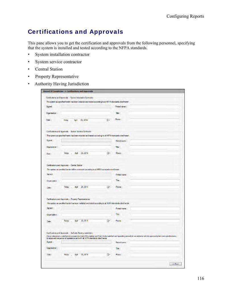
Configuring Reports
116
Certifications and Approvals
This pane allows you to get the certification and approvals from the following personnel, specifying that the system is installed and tested according to the NFPA standards. • System installation contractor• System service contractor• Central Station• Property Representative• Authority Having Jurisdiction

FS-Tools Programming Guide for the 200 Point Addressable Panel
117
To obtain the Certification and Approvals:
1. Type the Printed name, Organization, Title, Date and Phone details from the SystemInstallation Contractor.
2. Similarly fill in the details for System Service Contractor, Central Station, Property Representative and Authority Having Jurisdiction.
Click Prev to go back to Record of System Installation and System Operation. To configure the Inspection and Testing click File > NFPA Report Requisite > Inspection and Testing.
Inspection and Testing In FS-Tools, configuring the Inspection and Testing involves the following steps.
1. Configuring General Information
2. Configuring Type Transmission
3. Configuring the Signaling Line Circuits
a. Alarm Initiating Devices
b. Alarm Notification Appliances
c. Supervisory Signal-Initiating Devices
4. Configuring System Power supplies
5. Configuring Notifications Prior to Testing
6. Configuring System Tests and Inspections
7. Configuring Secondary Power
8. Configuring Combination Systems
9. Configuring Emergency Communication Equipment
10. Configuring Supervising Station Monitoring
11. Obtaining Notifications and Approvals
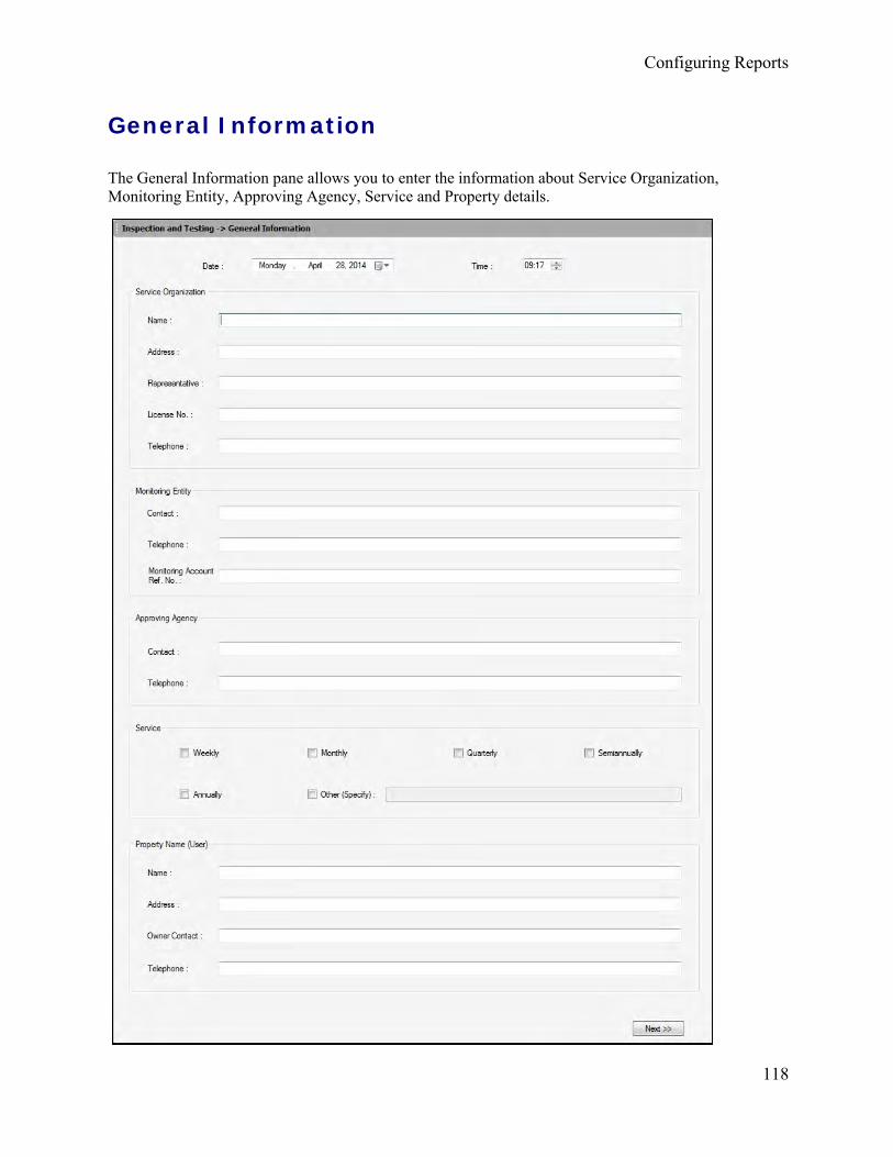
Configuring Reports
118
General Information
The General Information pane allows you to enter the information about Service Organization, Monitoring Entity, Approving Agency, Service and Property details.

119
FS-Tools Programming Guide for the 200 Point Addressable Panel
To configure the General Information:
Select the Date and Time for general information from the drop-down menus.
1. Enter the Name, Address, Representative, License Number and Telephone Number of theService Organization.
2. Enter the Contact, Telephone, and Monitoring Account Ref Number of the MonitoringEntity.
3. Enter the Contact and Telephone Number of the Approving Agency.
4. Select the required maintenance schedule from the Service checkbox.
5. Enter the Name, Address, Owner Contact, and Telephone number of the Property Name(User).
Click Next or click Type Transmission node in the left pane to configure the transmission type.

Configuring Reports
120
Type Transmission
The Type Transmission pane allows you to enter the details about the type of transmission, control unit, Model Number, Software revisions, date of service and configuration revision.
To configure the Type Transmission:
1. Select the required check box for Transmission Type.
2. Enter the Control Unit of the Manufacturer, Model No, Circuit Style, Number ofCircuits and Software Rev of the transmission.
3. Select the date of Last Date of System service and Last date of Software or Configurationrevision from the drop-down menus.
Click Next or click Signaling Line Circuits in the left pane to configure the signaling line circuits.
Click Prev to go back to General Information.

121
FS-Tools Programming Guide for the 200 Point Addressable Panel
Signaling Line Circuit
Alarm Initiating Devices and Circuit Information
The Alarm Initiating Devices and Circuits pane allows you to enter the information about the quantity of devices installed, Circuit style and Quantity of devices tested.

Configuring Reports
122
To configure the Alarm-Initiating Devices and Circuit Information:
1. Under Signaling Line circuits, enter the number of devices configured in fire panelconfiguration in Quantity for Loop1.
2. Select the Style configured in FACP programming for Loop1.
3. Under Alarm Initiating Devices and Circuit Information, enter the Quantity of DevicesInstalled in panel configuration for each of the following:
• Manual Fire Alarm boxes
• Ion Detectors
• Photo Detectors
• Duct Detectors
• Heat Detectors
• Water flow switches
• Supervisory switches
• Other (Specify)
4. Select the corresponding Circuit Style for the devices installed
5. Enter the corresponding Quantity of Devices Tested from the devices installed.
6. Click Enable to enable the Alarm Verification feature.
Note: When all the detectors are in alarm verification state, the radio button is enabled. By default, the button is disabled.
Click Next or click Alarm Notification Appliances in the left pane to configure the alarm notification appliances and circuit information.
Click Prev to go back to Type Transmission.

FS-Tools Programming Guide for the 200 Point Addressable Panel
Alarm Notification Appliances
The alarm notification appliances pane allows you to configure the quantity of appliances installed, tested, and circuit style.
To configure the Alarm Notification Appliances and circuit information:
1. Under Alarm Notification Appliances and Circuit Information, enter the Quantity ofAppliances Installed (configured in FACP programming under SLC and NAC for thefollowing:
• Bells• Homs• Chimes• Strobes• Speakers• Other (Specify)
2. Select the corresponding Circuit Style for the Appliances installed.3. Enter the corresponding Quantity of Appliances Tested from the Appliances installed.4. Click Yes to confirm the circuits monitored for integrity.Click Next or click Supervisory Signal - Initiating Devices in the left pane, to configure the Supervisory Signal - Initiating Devices and Circuit Information.
Click Prev to go back to Signaling Line Circuits -Alarm Initiating Devices and Circuits.
123

Configuring Reports
124
Supervisory Signal - Initiating Devices and Circuit Information
The Supervisory Signal - Initiating Devices pane allows you to enter the information about the quantity of devices installed, Circuit style and Quantity of devices tested.

125
FS-Tools Programming Guide for the 200 Point Addressable Panel
To configure the Supervisory Signal - Initiating Devices and Circuit Information:
1. Under Supervisory Signal - Initiating Devices and Circuit Information, enter the Quantity of Devices Installed for the following:
• Building Temp
• Site Water Temp
• Site Water Level
• Fire Pump Power
• Fire Pump Running
• Fire Pump Auto Position
• Fire Pump or Pump Controller Trouble
• Generator in Auto Position
• Generator or Controller Trouble
• Switch Transfer
• Generator Engine Running
• Other (Specify)
2. Select the corresponding Circuit Style for the devices installed.
3. Enter the corresponding Quantity of Devices Tested from the devices installed.
Click Next or click System Power Supplies in the left pane to configure the System Power Supply.
Click Prev to go back to Alarm Notification Appliances.

Configuring Reports
126
System Power Supplies
The system power supplies pane allows you to configure the primary power, secondary power, and the standby System.

FS-Tools Programming Guide for the 200 Point Addressable Panel
127
To configure the system power supply:
1. Enter the Nominal voltage value and Amps for the primary power source.
2. Enter the Overcurrent protection Type and Amps for the primary power source.
3. Enter the Location of primary supply panel board for the primary power source.
4. Enter the Disconnecting means location for the primary power source.
5. Under Secondary power, enter the name of the Storage Battery and its Amp Hr Rating forthe secondary power source.
6. Enter the Calculated capacity and Amp Hrs needed to operate the system for the secondarypower source.
7. Enter the name of the Engine driven generator dedicated to fire alarm system and its Amphour rating.
8. Enter the Location of fuel storage.
9. Under Emergency or Standby System, enter the name of the legally required standbysystem described in NFPA 70, Article 701.
10. Enter the Optional standby system described in NFPA 70, Article 702.
11. Enter the name of the Emergency system described in NFPA 70, Article 700.
12. Select the required check box under Battery type.
Click Next or click Notifications Prior to any Testing in the left pane to configure the Notifications.
Click Prev to go back to Supervisory Signal - Initiating Devices and Circuit Information.

Configuring Reports
128
Notifications Prior to Testing
The Notifications Prior to any testing pane allows you to set the notifications and time on monitoring entities, building occupants, and building Management.
To configure the Notifications:
1. Click the specific option to confirm the Notifications are made by monitoring Entity.
2. In the Who text box type the name of the person through whom the notifications are made.
3. Select the Time at which the notifications are made.
4. Repeat steps 1 through 3 for Building Occupants, Building Management, Others and AHJNotified of Any Impairments.
Click Next or click System Tests and Inspections in the left pane to configure the system tests and inspections.
Click Prev to go back to System Power Supplies.

FS-Tools Programming Guide for the 200 Point Addressable Panel
129
System Tests and Inspections
The system tests and inspection pane allows you to configure the test and inspections type for control units, interface equipment, lamps/LEDs, fuses, power supply, trouble signals, disconnect switches, and ground fault monitoring.
To configure the System Tests and Inspections:
Select the Visual or Functional checkbox for the following, and type any suitable comments:
• Control Unit• Interface Equipment• Lamps/LEDs• Fuses• Primary Power Supply• Trouble Signals• Disconnect Switches• Ground Fault Monitoring
Click Next or click Secondary Power in the left pane to configure the secondary power type.
Click Prev to go back to Notifications Prior to any Testing.

Configuring Reports
130
Secondary Power
The secondary power pane allows you configure the type of secondary power and notification appliances for panels.
To configure the Secondary power:
1. Under Type, select the Visual checkbox and type any comments for Battery Condition.2. Select the Functional checkbox and type any comment for Load Voltage, Discharge Test,Charger Test, and Specific Gravity.3. Select the Visual checkbox and type any comment for Transient Suppressors.4. Select the required checkbox for Remote Annunciators and type any comment.5. Under Notification Appliances, select the required checkbox and type any comments for theAudible, Visible and Speakers appliances.6. Select the Functional checkbox and type any comment for Voice Clarity.
Click Next or click Combination Systems in the left pane, to configure the combination systems.
Click Prev to go back to System Tests and Inspections.

131
FS-Tools Programming Guide for the 200 Point Addressable Panel
Combination Systems
The Combination Systems pane allows you to enter the information about different Devices/System and equipment.
To configure the Combination Systems:
1. Select the required checkboxes for Fire Extinguisher Device/System and Carbon MonoxideDetector/System.2. Specify other Device/System and select the appropriate checkboxes.3. Under Interface Equipment, specify/type the equipment and click the required checkboxes.4. Under Special Hazard Systems, specify/type the Systems and click the required checkboxes.5. Enter the description of the Special Procedure.Click Next or click Emergency Communication Equipment in the left pane to configure the Emergency Communication Equipment.
Click Prev to go back to Secondary Power.

Configuring Reports
132
Emergency Communication Equipment
The Emergency Communication Equipment pane allows you to configure the communication equipment.
To configure the Emergency Communication Equipment:
1. Under Emergency Communication Equipment select the appropriate checkbox and typethe comments for the following:
• Phone Set
• Phone Jacks
• Off Hook Indicator
• Amplifiers
• Tone Generators
• Call-in signal
• System Performance
Click Next or click Supervising Station Monitoring in the left pane to set the Notification and get the approvals.
Click Prev to go back to Combination Systems.

133
FS-Tools Programming Guide for the 200 Point Addressable Panel
Supervising Station Monitoring
The Supervising Station Monitoring pane allows you to configure the Station Monitoring devices.
To configure the Supervising Station Monitoring:
1. Under Supervising Station Monitoring,
a. Click the required Yes/No options.
b. Type or select the required time in the Time box.
c. Type any comments in the Comments text box for the following:
• Alarm Signal
• Alarm Restoration
• Trouble Signal
• Trouble Signal Restoration
• Supervisory Signal
• Supervisory Restoration
Click Next or click Notification and Approvals in the left pane to set the Notification and get the approvals.
Click Prev to go back to Emergency Communication Equipment.

Configuring Reports
134
Notifications and Approvals
The Notification and Approvals pane allows you to set testing and functional notifications and to get approval in accordance with the applicable NFPA standards.

135
FS-Tools Programming Guide for the 200 Point Addressable Panel
To set the Notifications and get the approval:
1. Under Notification that testing is complete,
a. Confirm whether or not Notifications are made.
b. Enter the name of the person through whom the notification and testing is completed in theWho text box.
c. Select the Time when the notifications are set for the following:
• Building Management
• Monitoring Agency
• Building Occupants
• Others
2. Under Not functioning correctly, enter the name of devices and system which are notfunctioning correctly and also enter the name of the system restored to normal operation.
3. Select the Date and Time to specify when the above testing is done.
4. Under Approvals, enter the Name of the Inspector who performed the testing in accordancewith NFPA standards.
5. Select the Date and Time and get the Signature.
6. Enter the Name of the Owner or Representative.
7. Select the Date and Time and get the Signature.
Click Next or click Upload Information in the left pane to upload the Device Maintenance Information in FS-Tools.
Click Prev to go back to Emergency Communication Equipment.

Configuring Reports
136
Upload Information
Device Maintenance Information
To upload the information, click File > NFPA Report Requisite > Inspection and Testing > Upload Information > Device Maintenance Information. The Device Maintenance Information pane appears.
To upload Device Maintenance information from the fire panel:
1. In the Device Maintenance Information window, click the Upload Data button. The UploadNFPA Requisites dialog box appears.

FS-Tools Programming Guide for the 200 Point Addressable Panel
137
2. Click the Connection Settings button. The Connection Settings dialog appears.
3. Select the required Communication Mode from the list. Settings for the selectedcommunication mode are displayed.
4. Enter the required information in the fields and click the Save and Exit button. The selectedCommunication Mode is displayed in the corresponding field.
5. Click the Connect button. The PC Panel Communication Status displays the progress andcommunication status.
Note: If the connection to PC Panel is successful, the Upload NFPA Requiste and View Upload Files buttons are enabled under Upload NFPA Requisite.

Configuring Reports
138
6. Click OK in the confirmation message.
7. Click Upload NFPA Requisite button under Upload NFPA Requisite. The device maintenance information is uploaded from the fire panel and the Device Maintenance Information table displays the uploaded data as shown below.
Note: If the Device Maintenance Information is not uploaded, you cannot view the Uploaded Files.
8. Click the Close button to close the Upload NFPA Requisites dialog box.
9. Click the Save to Database button. The Save confirmation box appears.
10. Click OK to confirm.
Click the Return to Main Screen button to view the main screen.
Click Prev to go back to the Notification and Approvals dialog box.

139
Reports Menu Configuration Data Report Using the Reports option in FS-Tools, you can generate the configuration data report, which gives the configuration information of the input, output, and optional modules, and the fire alarm system settings. This report is generated as a PDF file. You can store the reports to maintain the configuration information of the fire panel at different times and dates. A printout of the configuration data report helps in manual verification of the fire alarm system settings.
To generate the report:
1. Select a customer record from the initial customer screen, using the Find option if necessary.
2. Choose Reports > Configuration Data in the initial customer screen in FS-Tools.
Note: You can generate the configuration report only for the configuration saved in the FS-Tools database. You cannot generate the report for Factory Default configuration.
By default, the configuration data report is stored in the C:\FS-Tools\Reports folder.

Configuring Reports
140
Central Station Report Using the Reports option in FS-Tools, you can generate the central station report which prints the details of devices and their associated event codes. This report is displayed in a tabular format listing the Point troubles and their corresponding event codes. The report also displays the configured system event codes. This report can be generated as a PDF file and an Excel file.
Generate as PDF 1. Select a customer record from the initial customer screen. Use the Find option, if necessary.
2. Choose Reports > Central Station Report > Export To PDF in the initial customer screenin FS-Tools. The Central Station report for the selected customer is generated as a PDF file.
Note: You can generate the central station report only for the configuration saved in the FS-Tools database. You cannot generate the report for Factory Default configuration.
By default, the central station report is stored in the C:\FS-Tools\ReportsAddressable\PDFs.

141
FS-Tools Programming Guide for the 200 Point Addressable Panel
Generate as Excel File
1. Select a customer record from the initial customer screen. Use the Find option, if necessary.
2. hoose Reports > Central Station Report > Export To Excel in the initial customer screen in FS-Tools.
3. A central Station report for the selected customer is generated as a Excel file. By default, theconfiguration data report is stored in the C:\FS-Tools\ReportsAddressable\Excel Folder. Save the filewhere desired.
Note: You can generate the configuration report only for the configuration saved in the FS-Tools database. You cannot generate the report for a Factory Default configuration.

Reports Menu
142
NFPA Report
Record of Completion Report
Generate as PDF
1. Select a customer record from the initial customer screen, using the Find option if necessary.
2. Choose Reports > NFPA Report > Record of Completion > Export to PDF in the initialcustomer screen in FS-Tools.
The Record of Completion Report for the selected customer is generated as a PDF file.
By default, the Record of Completion Report data is saved to the C:\FS-Tools\ReportsAddressable\PDF folder.
Note: You can generate the configuration report only for the configuration saved in the FS-Tools database. You cannot generate the report for a Factory Default configuration.

FS-Tools Programming Guide for the 200 Point Addressable Panel
143
Generate as Excel File
1. Select a customer record from the initial customer screen, using the Find option if necessary.
2. Choose Reports > NFPA Report > Record of Completion > Export to Excel in the initial customerscreen in FS-Tools.
The Record of Completion Report for the selected customer is generated as an Excel file.
By default, the Record of Completion Report data is saved to the C:\FS-Tools\ReportsAddressable\Excel folder.
Note: You can generate the Record of Completion report only for the configuration saved in the FS-Tools database. You cannot generate the report for Factory Default configuration.

Reports Menu
144
Generate as Word Document
1. Select a customer record from the initial customer screen, using the Find option if necessary.
2. Choose Reports > NFPA Report > Record of Completion > Export to Word in the initial customerscreen in FS-Tools.
The Record of Completion Report for the selected customer is generated as a Word document.
By default, the Record of Completion Report data is stored in the C:\FS-Tools\ReportsAddressable\Word folder.
Note: You can generate the Record of Completion report only for the configuration saved in the FS-Tools database. You cannot generate the report for Factory Default configuration.

FS-Tools Programming Guide for the 200 Point Addressable Panel
145
Inspection and Testing Report
Generate as PDF
1. Select a customer record from the initial customer screen, using the Find option if necessary.
2. Choose Reports > NFPA Report > Inspection and Testing> Export to PDF in the initialcustomer screen in FS-Tools.
The Inspection and Testing Report for the selected customer is generated as a PDF file.
Note: You can generate the Inspection and Testing report only for the configuration saved in the FS-Tools database. You cannot generate the report for Factory Default configuration.
By default, the Inspection and Testing Report data is stored in the C:\FS-Tools\ReportsAddressable\PDF folder.

Reports Menu
146
Generate as Excel File
1. Select a customer record from the initial customer screen, using the Find option if necessary.
2. Choose Reports > NFPA Report > Inspection and Testing> Export to Excel in the initial customerscreen in FS-Tools.
The Inspection and Testing Report for the selected customer is generated as an Excel file.
Note: You can generate the Inspection and Testing report only for the configuration saved in the FS-Tools database. You cannot generate the report for Factory Default configuration.
By default, the Inspection and Testing Report data is stored in the C:\FS-Tools\ReportsAddressable\Excel folder.

FS-Tools Programming Guide for the 200 Point Addressable Panel
147
Generate as Word Document
1. Select a customer record from the initial customer screen, using the Find option if necessary.
2. Choose Reports > NFPA Report > Inspection and Testing> Export to Word in the initial customerscreen in FS-Tools.
The Inspection and Testing Report for the selected customer is generated as a Word document.
Note: You can generate the Inspection and Testing report only for the configuration saved in the FS-Tools database. You cannot generate the report for Factory Default configuration.
By default, the Inspection and Testing Report data is stored in the C:\FS-Tools\ReportsAddressable\Word folder.

148
Troubleshooting Panel Connection Lost Trouble: The following message is displayed when the connection is lost between the computer and fire panel.
Resolution: Check the serial port connection between the computer and the fire panel.

FS-Tools Programming Guide for the 200 Point Addressable Panel
149
FS-Tools Failed to Download Data to Panel
Problem: The following message is displayed in FS-Tools cannot download data to fire panel.
Resolution: Check the power connection for the fire panel which might be turned off.

150
Troubleshooting
FS-Tools Failed to Upload Data from Panel Problem: The following message is displayed when FS-Tools cannot upload data from fire panel.
Resolution: Check the power connection for the fire panel which might be turned off.

151
FS-Tools Programming Guide for the 200 Point Addressable Panel
Verify Secret Code Request Denied Trouble: The following message is displayed when the secret code verification fails and when the connection between the computer and fire panel fails.
Resolution: In the Upload/Download screen, use the Set Secret Code at Panel option to verify and if required, change the panel secret code.

Troubleshooting
152
Resolution: Supervise the field wiring for each zone for open circuits, shorts, and ground faults. All the faults are visually and audibly annunciated.
Other EventsProblem: The troubleshoot data, uploaded from the fire panel into FS-Tools, displays the detector sensitivity data, and LED and piezo status.

153
Contact Us Documentation Feedback Your feedback helps us keep our documentation up-to-date and accurate. If you have any comments or suggestions about our online Help or printed manuals, you can email us.
Please include the following information:
• Product name and version number (if applicable)
• Printed manual or online Help
• Topic Title (for online Help)
• Page number (for printed manual)
• Brief description of content you think should be improved or corrected
• Your suggestion for how to correct/improve documentation
Send email messages to:
Please note this email address is for documentation feedback only. If you have any technical issues, please contact Technical Services.
Technical SupportFor technical assistance, please contact the Fire•Lite Technical Services department at 1-800-627-3473.

154
Index A
ANN-80 35
ANN-ACC 32, 35
ANN-Bus Address 35
ANN-ECC 32, 35
ANN-I/O 39, 41
ANN-LED 34, 42, 45
ANN-S/PG 34
Annunciators 32
B
Banner 31
C
Central Station 18, 21
Central Station Report 144
Clock 30
Combination Systems 134
Comm Panel ID 18
Communicator 18, 19
Compare Configuration 79
Configuration 18
Central Station 18
Communicator 18, 21
Configuration Type 17
Input/Output 23, 25
NACs 25, 26, 27
Configuration Data 143
Connect/Disconnect to Panel 96
Contact 157
Customer 12, 13, 14, 15
D
Database Backup 80
Daylight Savings Time 30
Delete Template 78
Detectors 50
Download 89
Download Password 77
E
Export 82
F
Function Keys 48
I
Import 84, 85
Installing/Uninstalling 2, 9

FS-Tools Programming Guide for the 200 Point Addressable Panel
155
L
Last Configuration Date 88
M
Modules 58
N
NACs 25
NFPA Report 145, 148
R
Relays 23
Reports 101
Inspection and Testing 120, 123, 124, 125, 127, 128, 130, 131, 132, 134, 135, 136, 137
Record of Completion 103, 104, 106, 107, 108, 111, 112, 113, 115, 117, 118
Upload Information 138
Restore Backup 81
Run 87
S
Simulation 69
SLC Loop 49
Detectors 50, 55, 56, 64
Modules 58, 64, 67
System Requirements 9
System Settings 28
T
Troubleshooting 152, 153, 154, 155
U
Upload Information 73, 94
History Data 74
System Status Data 75
Walktest Data 74
V
Verify Setup 68
W
Write Access 86
Z
Zones 23

One Fire-Lite Place, Northford, CT 06472-1601 USAUSA - Phone: (203) 484-7161Canada - Phone: (905) 856-8733www.firelite.com


![Setup Change Doc - Fin[1]](https://img.dokumen.tips/doc/110x75/577d2a051a28ab4e1ea87f5d/setup-change-doc-fin1.jpg)