Embed Size (px)
Citation preview

1
Programmable
Interval Timer - 8254
CEN433
King Saud University
Dr. Mohammed Amer Arafah
Mohammed Amer Arafah2CEN433 - King Saud University
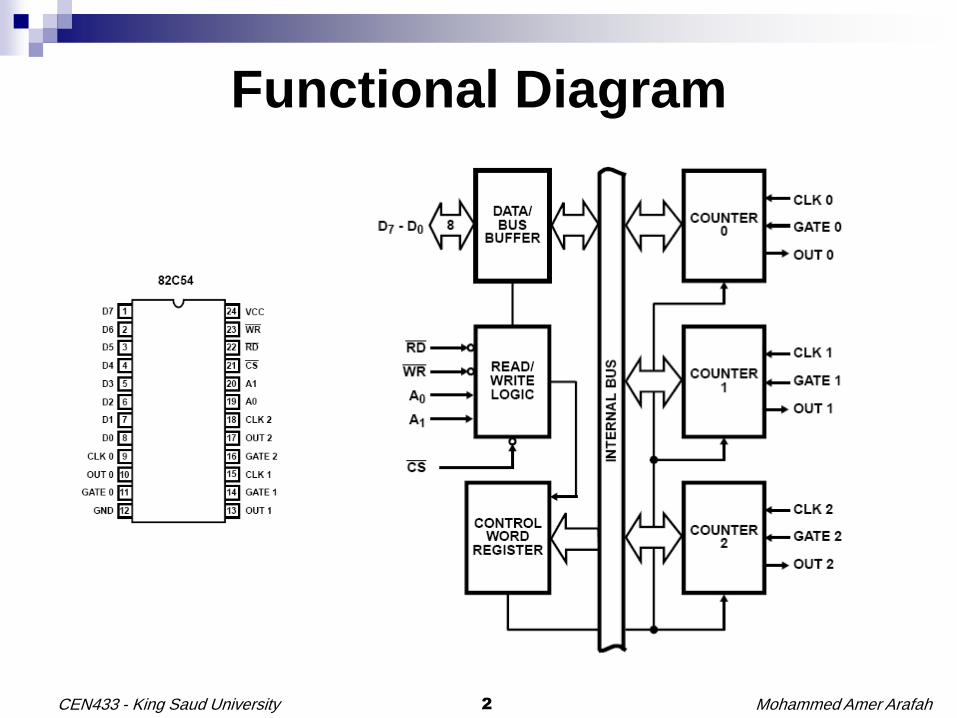
Functional Diagram

Mohammed Amer Arafah3CEN433 - King Saud University
8254: Pin Description

Mohammed Amer Arafah4CEN433 - King Saud University
8254: Read/Write Operations Summary

Mohammed Amer Arafah5CEN433 - King Saud University
8254 System Interface

Mohammed Amer Arafah6CEN433 - King Saud University
Control Word Format

Mohammed Amer Arafah7CEN433 - King Saud University
Possible Programming Sequence

Mohammed Amer Arafah8CEN433 - King Saud University
Write Operations
The programming procedure for the 82C54 is very flexible.
Only two conventions need to be remembered:
1. For Each Counter, the Control Word must be written
before the initial count is written.
2. The initial count must follow the count format specified
in the Control Word (least significant byte only, most
significant byte only, or least significant byte and then
most significant byte).

Mohammed Amer Arafah9CEN433 - King Saud University
Programming the 8254MOV DX, TCWMOV AL, 00110110B ; Control Word of Counter0: LSB then MSB, Mode 3, BinaryOUT DX, ALMOV DX, TCWMOV AL, 01110110B ; Control Word of Counter1: LSB then MSB, Mode 3, BinaryOUT DX, ALMOV DX, TCWMOV AL, 10110110B ; Control Word of Counter2: LSB then MSB, Mode 3, BinaryOUT DX, AL
; Initialize value of Counter 0MOV DX, COUNTER0MOV AL, Counter0_LSB ;LSB of Counter 0OUT DX, ALMOV AL, Counter0_MSB ;MSB of Counter 0OUT DX, AL
; Initialize value of Counter 1MOV DX, COUNTER1MOV AL, Counter1_LSB ;LSB of Counter 1OUT DX, ALMOV AL, Counter1_MSB ;MSB of Counter 1OUT DX, AL
; Initialize value of Counter 2MOV DX, COUNTER2MOV AL, Counter2_LSB ;LSB of Counter 2OUT DX, ALMOV AL, Counter2_MSB ;MSB of Counter 2OUT DX, AL

Mohammed Amer Arafah10CEN433 - King Saud University
Counter Internal Block Diagram

Mohammed Amer Arafah11CEN433 - King Saud University
8254: Read Operation
There are three possible methods for reading a counter:
A Simple Read Operation.
The Counter Latch Command.
The Read-Back Command.

Mohammed Amer Arafah12CEN433 - King Saud University
8254: Counter Latch Command
This Counter Latch Command is written to the Control Word
Register, which is selected when A1 A0 = 11.
The SC1 and SC0 bits select one of the three counters.
D5 D4 = 00 designates Counter Latch Command.
The selected counter's output latch (OL) latches the count at the
time Counter Latch Command is received.
The count is held in the OL until it is read by the CPU (or until the
counter is reprogrammed).
The count is then unlatched automatically and the OL returns to
"following" the counting element (CE).
If the counter is latched, and then latched again before the count is
read, the second Counter Latch Command is ignored.

Mohammed Amer Arafah13CEN433 - King Saud University
8254: Counter Latch Command

Mohammed Amer Arafah14CEN433 - King Saud University
8254: Counter Latch Command
; Latching Counter 0
MOV DX, TIMER_PORT3
MOV AL, 00000000B ; Count Latched for Counter 0
OUT DX, AL
; Reading Counter 0
MOV DX, TIMER_PORT0
IN AL, DX

Mohammed Amer Arafah15CEN433 - King Saud University
8254: Read-Back Command The Read-Back Command allows the user to check the count
value, programmed mode, and current states of the OUT pin and
NULL Count flag of the selected counter(s).
The Read-Back Command is written into the Control Word
Register.
The Read-Back Command may be used to latch multiple counter
output latches(s) by setting COUNT/ bit D5 = 0 and selecting the
desired counters.
A single Read-Back Command is equivalent to several Count
Latch Commands.
Each Counter's latched count is held in the OL until it is read by
CPU (or the counter is reprogrammed).
The counter is automatically unlatched when read, but other
counters remain latched until they are read.

Mohammed Amer Arafah16CEN433 - King Saud University
8254: Read-Back Command
If multiple Read-Back Command are issued to the same counter
without reading the count, all but the first are ignored; i.e., the count
which will be read is the count at the time the first Read-Back
Command was issued.
The Read-Back Command may also be used to latch status
information of selected counter(s) by setting STATUS/ bit D4 = 0.
Status must be latched to be read; status of a counter is accessed
by a read from that counter.
If multiple status latch operations of the counter(s) are performed
without reading the status, all but the first are ignored.
If both count and status of a counter are latched, the first read
operation of that counter will return latched status. The next one or
two reads return latched count.

Mohammed Amer Arafah17CEN433 - King Saud University
8254: Read-Back Command
Read-Back Command Example:

Mohammed Amer Arafah18CEN433 - King Saud University
8254: Read-Back Command
; Count and Status Latched for Counter 0
MOV DX, TIMER_PORT3
MOV AL, 11000010B ; Count Latched for Counter 0
OUT DX, AL
; Reading the Latched Status for Counter 0
MOV DX, TIMER_PORT0
IN AL, DX ; Reading Status
MOV AH, AL
; Reading the Latched Count for Counter 0
IN AL, DX ; Reading LSB of Counter 0
MOV BL, AL
IN AL, DX ; Reading MSB of Counter 0
MOV BH, AL

Mohammed Amer Arafah19CEN433 - King Saud University
8254: Status Byte

Mohammed Amer Arafah20CEN433 - King Saud University
Modes of Operation
Mode 0: Interrupt on Terminal Count
Mode 1: Hardware Retriggerable One-Shot
Mode 2: Rate Generator
Mode 3: Square Wave Mode
Mode 4: Software Triggered Mode
Mode 5: Hardware Triggered Mode

Mohammed Amer Arafah21CEN433 - King Saud University
Mode 0: Interrupt on Terminal Count
Freeze
• At the rising edge of WR/ (Control Word), OUT = low.
• At the first falling edge of CLK after the rising edge
of WR/ (LSB), CRCE.
• GATE is level sensitive.
• GATE is sampled at the rising edge of CLK.
• Decrement the counter at the falling edge, if the
sample of GATE is high. Otherwise, freeze.

Mohammed Amer Arafah22CEN433 - King Saud University
Mode 1: Hardware Retriggerable One-Shot
• At the rising edge of WR/ (Control Word), OUT = high.
• At the first falling edge of CLK after the rising edge of
GATE, CRCE.
• At the first falling edge of CLK after the rising edge of
GATE, reinitialize CE with the last value written to CR.

Mohammed Amer Arafah23CEN433 - King Saud University
Mode 2: Rate Generator
Freeze
• At the rising edge of WR/ (Control Word), OUT = high.
• At the first falling edge of CLK after the rising edge of
WR/ (LSB), CRCE.
• When counter reaches to value 1, it is reloaded with
the value of CR at the next falling edge of CLK.
• GATE is sampled at the rising edge of CLK.
• Decrement the counter at the falling edge, if the
sample of GATE is high. Otherwise, freeze.
• At the first falling edge of CLK after the rising edge of
the GATE, reinitialize CE.

Mohammed Amer Arafah24CEN433 - King Saud University
Mode 3: Square Wave Mode
Freeze
• At the rising edge of WR/ (Control Word), OUT = high.
• At the first falling edge of CLK after the rising edge of
WR/ (LSB), CRCE.
• GATE is sampled at the rising edge of CLK.
• At the first falling edge of CLK after the rising edge of
the GATE, reinitialize CE.

Mohammed Amer Arafah25CEN433 - King Saud University
Mode 4: Software Triggered Mode
• At the rising edge of WR/ (Control Word), OUT = high.
• At the first falling edge of CLK after the rising edge of
WR/ (LSB), CRCE.
• GATE is level sensitive.
• GATE is sampled at the rising edge of CLK.
• Decrement the counter at the falling edge, if the
sample of GATE is high. Otherwise, freeze.
• When counter reaches to zero, it wraps around to the
highest value.
Freeze

Mohammed Amer Arafah26CEN433 - King Saud University
Mode 5: Hardware Triggered Mode
• At the rising edge of WR/ (Control Word), OUT = high.
• At the first falling edge of CLK after the rising edge of
GATE, CRCE.
• At the first falling edge of CLK after the rising edge of
GATE, reinitialize CE with the last value written to CR.
• When counter reaches to zero, it wraps around to the
highest value.

Mohammed Amer Arafah27CEN433 - King Saud University
Gate Pin Operations Summary

Mohammed Amer Arafah28CEN433 - King Saud University
Minimum and Minimum Initial Counts

Mohammed Amer Arafah29CEN433 - King Saud University
Example 1
100 KHz Square Wave:
Mode 3
f Out = f in / n
n = 8000 KHz/100 KHz = 80d
200 KHz non-square wave:
Mode 2
f Out = f in / n
n = 8000 KHz/200 KHz = 40d
A1 A0 Address Port
0 0 700H Counter 0
0 1 701H Counter 1
1 0 702H Counter 2
1 1 703H Control Word

Mohammed Amer Arafah30CEN433 - King Saud University
Example 1
;A procedure that programs the 8254 timer
TIME PROC NEAR USES AX DX
MOV DX, 703H ; Control register
MOV AL, 00010110B ; Program counter 0: Mode 3, LSB only
OUT DX, AL
MOV AL, 01010100B ; Program counter 1: Mode 2, LSB only
OUT DX, AL
MOV DX, 700H ; Counter 0
MOV AL, 80 ; Load initial count 80d into counter 0
; LS byte of initial count
OUT DX, AL
MOV DX, 701H ; Counter 1
MOV AL, 40 ; Load initial count 40d into counter 1
OUT DX, AL
MOV AL, 0 ;Then MS byte of initial count
OUT DX, AL
RET
TIME ENDP

Mohammed Amer Arafah31CEN433 - King Saud University
Example 2: DC Motor Speed and Direction Control-Hardware

Mohammed Amer Arafah32CEN433 - King Saud University
Example 2: DC Motor Speed and Direction Control - Timing

Mohammed Amer Arafah33CEN433 - King Saud University
;AH determines the speed and direction of the motor where AH is between 00H and FFH.
CNTR EQU 703H ; PIT Control Word
CNT0 EQU 700H
CNT1 EQU 701H
COUNT EQU 30720
SPEED PROC NEAR USES BX DX AX
MOV BL,AH ;calculate count corresponding to AH: AH has speed control byte (0128255)
MOV AX,120
MUL BL ; Multiply AH (speed input) by 120
MOV BX,AX ; result in AX, save in BX (BX has AH x 120)
MOV AX,COUNT
SUB AX,BX
MOV BX,AX ; Subtract from 30720, Now BX has 30720 – AH x 120 = waiting count
MOV DX,CNTR
MOV AL,00110100B ; program control word
OUT DX,AL ; for counter 0: Binary, Mode 2, 2 bytes R/W
MOV AL,01110100B ; same for counter 1
OUT DX,AL ; but do not start it yet by loading COUNT- do this after waiting time
MOV DX,CNT1 ; program counter 1 to generate the clear (#CLR) signal for Q (free-running)
MOV AX,COUNT ;
OUT DX,AL ; LS byte of 30720 first
MOV AL,AH
OUT DX,AL ; then MS byte
.REPEAT ; wait for counter 1 count to reach Waiting Count in BX
IN AL,DX ; Read LS byte of counter 1 (goes as AL)
XCHG AL,AH ; Put it in AH
IN AL,DX ; Read MS byte of counter 1 (goes as AL)
XCHG AL,AH ; swap AL and AH to put things back to order
.UNTIL BX == AX
MOV DX,CNT0 ; program counter 0
MOV AX,COUNT ; to generate a set (#PS) for Q (free-running) after that waiting
; delay by Counter 1. Note you also load COUNT as with Counter 1
OUT DX,AL ; Actual outputting LS byte then MS byte
MOV AL,AH
OUT DX,AL
RET
SPEED ENDP
Example 2: DC Motor Speed and Direction Control-Software

Mohammed Amer Arafah34CEN433 - King Saud University
Example 2: DC Motor Speed and Direction Control - Timing
Mohammed Amer Arafah35CEN433 - King Saud University
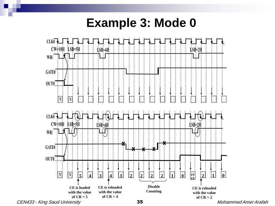
5 4 3 4 3 2 22 2 1 0 FF
FF2 1 0
Disable
CountingCE is loaded
with the value
of CR = 5
CE is reloaded
with the value
of CR = 4
CE is reloaded
with the value
of CR = 2
Example 3: Mode 0

Mohammed Amer Arafah36CEN433 - King Saud University
Example 4: Mode 1
NN
N N 5 4 3 2 FF
FF1 FF
FE0 3 2 1
CE is loaded with
the value of CR = 5
CE is loaded with
the value of CR = 2
NN 2 1 0
CE is loaded with
the value of CR = 3

Mohammed Amer Arafah37CEN433 - King Saud University
Example 5: Mode 2
4 3 2 1 4 3 43 3 2 1 2 1 2 1
CE is loaded with the
new value of CR = 2
Disable
CountingCE is loaded
with the value
of CR = 4
CE is loaded
with the value
of CR = 4

Mohammed Amer Arafah38CEN433 - King Saud University
Example 6: Mode 3
6 4 2 6 4 4 46 2 2 2 0 2 2 0
Sets outputs high
asynchronouslyCE is loaded with
the new value of
CR=2
CE is loaded
with the value
of CR = 6
Disable
CountingCE is loaded
with the value
of CR = 6

Mohammed Amer Arafah39CEN433 - King Saud University
Example 7: Mode 4
5 4 3 4 3 2 22 2 1 0 FF
FF2 1 0
Disable
Counting
CE is loaded
with the value
of CR = 5
CE is reloaded
with the value
of CR = 4
CE is reloaded
with the value
of CR = 2

Mohammed Amer Arafah40CEN433 - King Saud University
Example 8: Mode 5
NN
N N 5 4 3 2 FF
FF1 FF
FE0 3 2 1
CE is loaded with
the value of CR = 5
CE is loaded with
the value of CR = 2
NN 2 1 0
CE is loaded with
the value of CR = 3

Mohammed Amer Arafah41CEN433 - King Saud University
Example 9
A 22.1184 MHz crystal is connected to a clock generator (8284A). The PCLK
output of the 8284A is connected to the CLK0 input of 8254. You need to
generate 14400 × 64 Hz square wave clock output using the counter 0 of the
8254. Write the instructions to initialize the 8254.
; 8254 initialization
MOV DX, TCW
MOV AL, 00010110B ; Control Word
OUT DX, AL
;
MOV DX, COUNTER0
MOV AL, 4H ;LSB
OUT DX, AL
Solution:
C0_LSB = (22.1184×10⁶ /6) / (14400×64)
C0_LSB = 4

Mohammed Amer Arafah42CEN433 - King Saud University
Examples
; Example 10: Initialize value of Counter 0 to 20d
MOV DX, COUNTER0
MOV AL, 20 ;LSB
OUT DX, AL
; Example 11: Initialize value of Counter 0 to 256d
MOV DX, COUNTER0
MOV AL, 0 ;LSB
OUT DX, AL
; Example 12: Initialize value of Counter 0 to 1000d
MOV DX, COUNTER0
MOV AX, 1000
OUT DX, AL ;LSB
MOV AL, AH
OUT DX, AL ;MSB
; Example 13: Initialize value of Counter 0 to 03E8H
MOV DX, COUNTER0
MOV AL, 0E8H
OUT DX, AL ;LSB
MOV AL, 03H
OUT DX, AL ;MSB

Mohammed Amer Arafah43CEN433 - King Saud University
Example 14
6 4 2 6 4 2 2 6 4 2 4 2 4 2 0

Mohammed Amer Arafah44CEN433 - King Saud University
Example 15

Mohammed Amer Arafah45CEN433 - King Saud University
Solution of Example 15
6 4 2 0 6 4 4 4 6 4 2 0 6
4 2 6 4 2 0 8 6 4 2 8 6 6 8 6 4