Embed Size (px)
Citation preview
Latches
Outline
Pulse-Triggered Latch S-R Latch Gated S-R Latch Gated D Latch
Outline
Pulse-Triggered Latch S-R Latch Gated S-R Latch Gated D Latch
S-R Latch
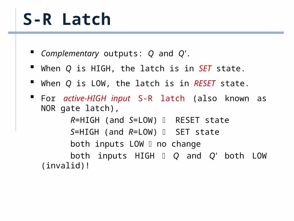
Complementary outputs: Q and Q'.
When Q is HIGH, the latch is in SET state.
When Q is LOW, the latch is in RESET state.
For active-HIGH input S-R latch (also known as NOR gate latch),
R=HIGH (and S=LOW) RESET state
S=HIGH (and R=LOW) SET state
both inputs LOW no change
both inputs HIGH Q and Q' both LOW (invalid)!
S-R Latch
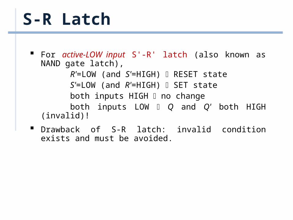
For active-LOW input S'-R' latch (also known as NAND gate latch),
R'=LOW (and S'=HIGH) RESET stateS'=LOW (and R'=HIGH) SET stateboth inputs HIGH no changeboth inputs LOW Q and Q' both HIGH (invalid)!
Drawback of S-R latch: invalid condition exists and must be avoided.
S-R Latch
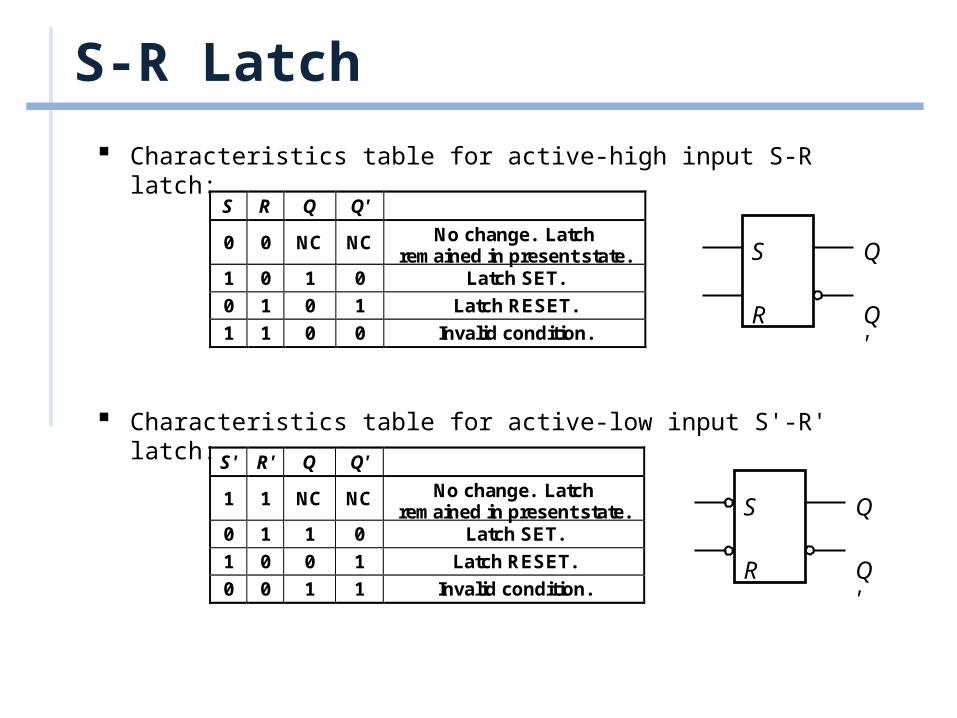
Characteristics table for active-high input S-R latch:
Characteristics table for active-low input S'-R' latch:
S R Q Q'
0 0 NC NC No change. Latchremained in present state.
1 0 1 0 Latch SET.
0 1 0 1 Latch RESET.
1 1 0 0 Invalid condition.
S' R' Q Q'
1 1 NC NC No change. Latchremained in present state.
0 1 1 0 Latch SET.
1 0 0 1 Latch RESET.
0 0 1 1 Invalid condition.
S
R
Q
Q'
S
R
Q
Q'
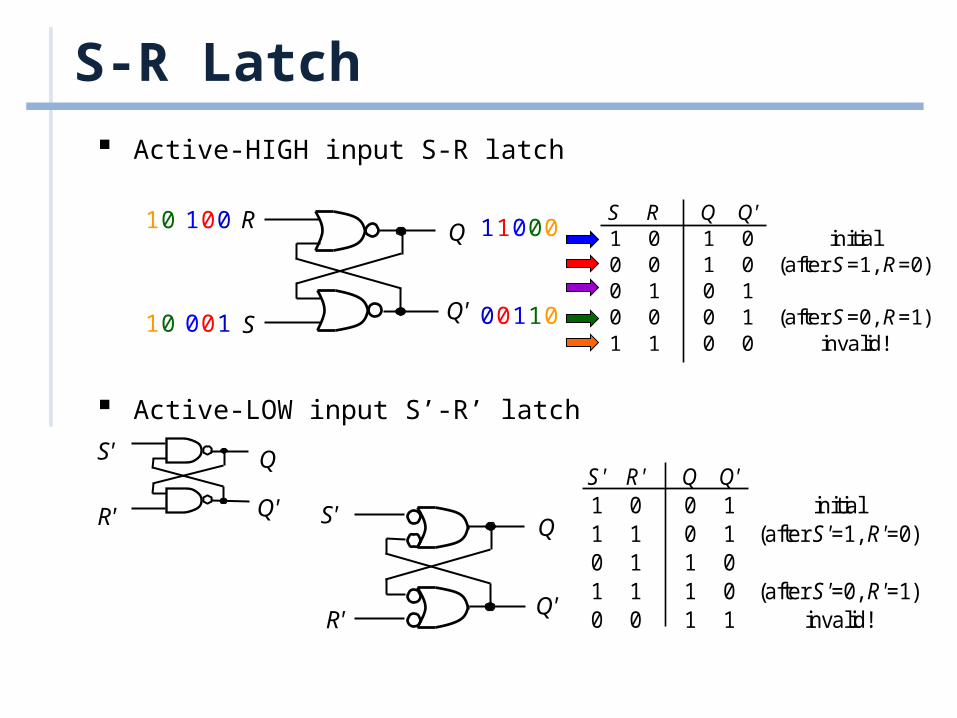
S-R Latch Active-HIGH input S-R latch
Active-LOW input S’-R’ latch
R
S
Q
Q'
S R Q Q' 1 0 1 0 initial 0 0 1 0 (after S=1, R=0) 0 1 0 1 0 0 0 1 (after S=0, R=1) 1 1 0 0 invalid!
S' R' Q Q' 1 0 0 1 initial 1 1 0 1 (after S'=1, R'=0) 0 1 1 0 1 1 1 0 (after S'=0, R'=1) 0 0 1 1 invalid!
S'
R'
Q
Q' S'
R'
Q
Q'
0
1
1
0
0
0
1
0
1
0
0
1
0
0
0
1
1
1
0
0
Outline
Pulse-Triggered Latch S-R Latch Gated S-R Latch Gated D Latch
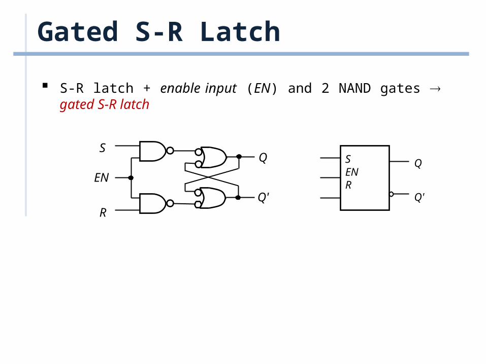
Gated S-R Latch
S-R latch + enable input (EN) and 2 NAND gates gated S-R latch
S
R
Q
Q'
EN
SENR
Q
Q'
Gated S-R Latch
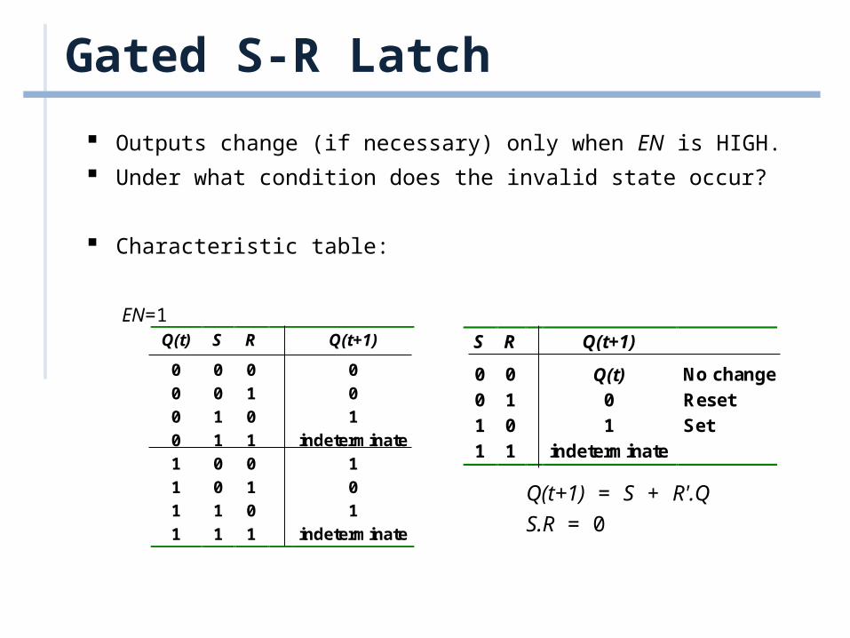
Outputs change (if necessary) only when EN is HIGH.
Under what condition does the invalid state occur?
Characteristic table:
Q(t) S R Q(t+1)
0 0 0 0
0 0 1 0
0 1 0 1
0 1 1 indeterminate
1 0 0 1
1 0 1 0
1 1 0 1
1 1 1 indeterminate
EN=1S R Q(t+1)
0 0 Q(t) No change
0 1 0 Reset
1 0 1 Set
1 1 indeterminate
Q(t+1) = S + R'.Q
S.R = 0
Outline
Pulse-Triggered Latch S-R Latch Gated S-R Latch Gated D Latch
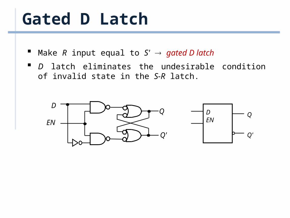
Gated D Latch
Make R input equal to S' gated D latch
D latch eliminates the undesirable condition of invalid state in the S-R latch.
DEN
Q
Q'
DQ
Q'
EN
Gated D Latch
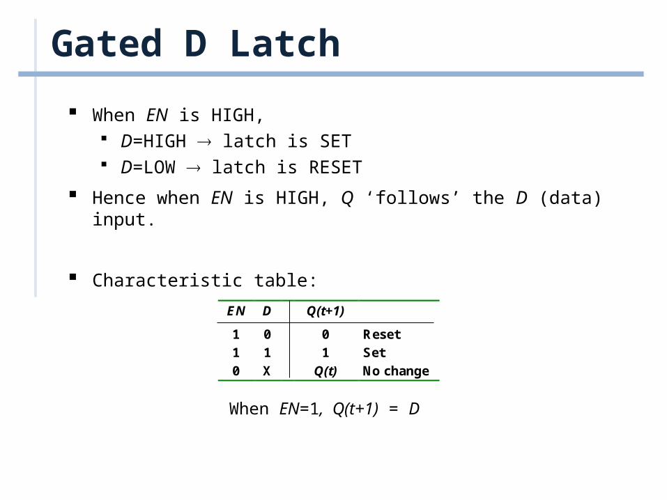
When EN is HIGH, D=HIGH latch is SET D=LOW latch is RESET
Hence when EN is HIGH, Q ‘follows’ the D (data) input.
Characteristic table:
When EN=1, Q(t+1) = D
EN D Q(t+1)
1 0 0 Reset
1 1 1 Set
0 X Q(t) No change
Latch Circuits: Not Suitable
Latch circuits are not suitable in synchronous logic circuits.
When the enable signal is active, the excitation inputs are gated directly to the output Q. Thus, any change in the excitation input immediately causes a change in the latch output.
The problem is solved by using a special timing control signal called a clock to restrict the times at which the states of the memory elements may change.
This leads us to the edge-triggered memory elements called flip-flops.
![New Page 1 []€¦ · NAI LATCHES FOR FT-620B COVER. NAI LATCH H322-2-1 Yaesu # S3000001 NAI LATCH H322-2-3-1 Yaesu# S3000005 One of these is the pin and the other is the circular](https://img.dokumen.tips/doc/110x75/5f10f698b7823c463e15f6c5/new-page-1-nai-latches-for-ft-620b-cover-nai-latch-h322-2-1-yaesu-s3000001.jpg)