Embed Size (px)
Citation preview
Simulator Exercise Guide Job Aid Page 1 of 66
SEG#_ROI/SOI-06-SE-SC1__ Rev ; __A___
KPS-SEG1-L-RO/SRO-A-11022010-048
SITE: Kewaunee Power Station
PROGRAM: RO/SRO License Training
PROGRAM No. ROI/SRO-TP
COURSE: 2011 NRC License Exam Course #: ROI-06-SE-SC1 SOI-06-SE-SC1
Total Time 2 hours
Prepared by: Andrew Fahrenkrug /s 11/03/2010 Printed Name Instructor’s Signature Date
Reviewed by: Jeffrey A. Hinze /s 11/03/2010 (Optional) Printed Name Simulator Development Checklist
Instructor Signature Date
Reviewed by: Andrew Fahrenkrug /s 09/17/2010 (Optional) Printed Name Simulator Validation Checklist
Signature Date
Approved by: Randy Hasting /s 11/09/2010 Printed Name Training Supervisor Date
Approved by: Mark Goolsbey /s 11/11/2010 Printed Name Facility Representative Date
Simulator Exercise Guide SEG#_ROI/SOI-06-SE-SC1__ Rev ; __A___
KPS-SEG1-L-RO/SRO-A-11022010-048
Job Aid Page 2 of 66
REQUIREMENTS
Goal of Training: Evaluate crew response and performance for the following events: • Power reduction for a minimum generation warning from 100% to 95%
per OP-KW-GOP-307 • Controlling Prz pressure blue channel (III), PT-431 fails high • FW-7B controller output signal fluctuates resulting in unstable operation
of FW-7B, SG B Feed Reg Valve • NI Red Channel, N41, fails low with outward rod motion • SGTR occurs in SG B • AFW Pump A fails to auto start on low SG level or SI signal with manual
start available • SRO/US analysis of plant conditions for Technical Specification
application
Learning Objectives: While responding as the RO/BOP satisfactorily MEET the performance requirements in TR-AA-400 for the following competencies
a. Understand and Interpret Annunciator and Alarm Signals b. Diagnose Events and Conditions based on Signals and Reading c. Understand Plant and System Response d. Comply with and Use Procedures and Technical Specifications e. Operate the Control Board f. Communicate and Interact with Other Crew Members
(RO4-06-SED01.002) ROI-06-SE-SC01.001 / SOI-06-SE-SC01.001 While responding as the US satisfactorily MEET the performance requirements in TR-AA-400 for the following competencies
a. Understand and Interpret Annunciator and Alarm Signals b. Diagnose Events and Conditions based on Signals and Reading c. Understand Plant and System Response d. Comply with and Use Procedures and Technical Specifications e. Operate the Control Board f. Communicate and Interact with Other Crew Members g. Direct Shift Operations h. Comply with and Use Technical Specifications
(RO4-06-SED01.003) SOI-06-SE-SC01.002
As the US DETERMINE the appropriate event classification in accordance with EPIP-AD-02,”Emegency Classification Determination”. (This objective will be completed at the end of the scenario and may be waived at the lead evaluator’s discretion.) SOI-06-SE-SC01.003
Simulator Exercise Guide SEG#_ROI/SOI-06-SE-SC1__ Rev ; __A___
KPS-SEG1-L-RO/SRO-A-11022010-048
Job Aid Page 3 of 66
Prerequisites: Enrolled in current ILT class and recommended by station management to take an NRC license exam.
Training Resources: Simulator KPS Exam Team Member NRC Examiners
Simulator Exercise Guide SEG#_ROI/SOI-06-SE-SC1__ Rev ; __A___
KPS-SEG1-L-RO/SRO-A-11022010-048
Job Aid Page 4 of 66
References: KPS Technical Specifications (ITS) KPS Technical Requirements Manual (TRM) EOL Standard Reactivity Plan (100% to 94% @ 0.5%/min) OP-AA-100 Conduct of Operations OP-AP-300 Reactivity Management OP-AP-104 Emergency and Abnormal Operating Procedures ARP 47011-B, RADIATION INDICATION HIGH ARP 47012-B, RADIATION INDICATION ALERT ARP 47032-J, POWER RANGE NEGATIVE RATE CHANNEL ALERT ARP 47033-K, POWER RANGE CHANNEL DEVIATION ARP 47041-C PRESSURIZER PRESSURE 2385 ARP 47043-C PRESSURIZER CONTROL PRESS ABNORMAL ARP 47043-D PRESSURIZER PRESSURE LOW ARP 47043-E, PRESSURIZER LEVEL DEVIATION ARP-47043-J CHARGING PUMP IN AUTO HIGH/LOW ARP-47044-F ICCMS PANEL TROUBLE ARP 47033-25, TLA-10 STEAM GENERATOR TILTS ARP 47033-35, TLA-15 RMS ABOVE NORMAL ARP 47061-E, S/G B SF > FF ARP 47061-F, S/G B FEEDFLOW EXCESSIVE ARP 47062-D, S/G B PROGRAM LEVEL DEVIATION ARP 47062-E, S/G B BYPASS CV LEVEL DEVIATION AOP-GEN-001, Operator Immediate Actions AOP-MISC-001, Response to Instrument Failure AOP-II-001, Abnormal Inadequate Core Cooling Monitoring (ICCM) System AOP-FW-001, Abnormal Feedwater System Operation AOP-RC-004, Steam Generator Tube Leak AOP-RC-001, Reactor Coolant Leak E-0, Reactor Trip Or Safety Injection E-3, Steam Generator Tube Rupture GOP-307, Hold at Power Greater Than 35% NOP-CVC-001, Boron Concentration Control NOP-CVC-002, Charging And Volume Control NOP-TB-001, Turbine and Generator Operation NOP-HD-001 Heater and Moisture Separator Drain and Bleeder Steam System SP-32-113 Gaseous Radioactive Effluents Reports for Continuous Releases NOP-RBV-002 Reactor Building Vent System Cold Operations and Making Releases
Simulator Exercise Guide SEG#_ROI/SOI-06-SE-SC1__ Rev ; __A___
KPS-SEG1-L-RO/SRO-A-11022010-048
Job Aid Page 5 of 66
Commitments: Per Outline submitted to NRC for 2011 Operating exam
Evaluation Method: Dynamic Simulator
Historical Record: Initial Issue
Operating Experience: Not required for evaluations
Related PRA Information:
Initiating Event with Core Damage Frequency:Total CDF/LERF (3.6E-5/yr)/(1.6E-06/yr)
• Steam Generator Tube Rupture – 3% CDF / 61.2%% LERF Important Components:
System
CDF Importance Rank LERF Importance Rank
AFW 4th 6 th
Important Operator ActionsCDF - None
LERF – Isolate ruptured SG an initiate cooldown and depressurization
Simulator Exercise Guide SEG#_ROI/SOI-06-SE-SC1__ Rev ; __A___
KPS-SEG1-L-RO/SRO-A-11022010-048
Job Aid Page 6 of 66
OVERVIEW
1. Standard IC-13 (100% End of Life equilibrium Xe) INITIAL CONDITIONS:
2. Containment vent using the Train B Post-LOCA path is in progress to reduce Containment pressure 3. The following equipment is OOS:
• PR-2A PORV has seat leakage and PR-1A, PORV Block Valve, is closed and energized satisfying LCO 3.4.11, Condition A.
• Turbine Driven AFW Pump due to corrective maintenance on its Aux Lube Oil Pump, tagout has just been hung
4. R-11/12 Sample Return is aligned to containment
SEQUENCE OF EVENTS: Event 1:
• Station Management has directed back down initiated at ½% per minute using Standard Reactivity Plan. Target power level is 95% (less than 1673 MWt).
Power reduction to 95% power as directed by Plant Management due to minimum generation warning
• The ATC Operator will be responsible for necessary boration(s), and monitoring rod motion, ΔI, and rod position (limits).
• The BOP Operator will control the turbine load reduction, adjust Heater Drain Pump B speed and monitor power and SG levels.
Simulator Exercise Guide SEG#_ROI/SOI-06-SE-SC1__ Rev ; __A___
KPS-SEG1-L-RO/SRO-A-11022010-048
Job Aid Page 7 of 66
Event 2:After the power decrease the controlling PRZR Pressure blue channel, PT-431, fails high to 2500 psig. This will result in PRZR heater output going to zero, and PRZR Spray valves opening. Actual PRZR pressure will lower. The crew will perform actions of AOP-GEN-001, Immediate Operator Actions, Attachment H for Pressurizer Spray Valves Open and/or the ARP(s) associated with High Pressure alarms. The failed instrument will be addressed using AOP-MISC-001, Response to Instrument Failure, Attachment G Pressurizer Pressure.
Controlling PRZ pressure blue channel (III), PT-431 fails high.
Technical Specifications:
• TS 3.3.1 (Reactor Protection System (RPS) Instrumentation) Condition A One or more Functions with one or more required channels or trains inoperable. Required Action A.1 enter the condition referenced in Table 3.3.1-1 for the channel(s) or train(s) with a completion time of immediately.
• TS 3.3.1 (Reactor Protection System (RPS) Instrumentation) Condition E one channel inoperable with Required Action E.1 to place channel in trip with a completion time of 72 hours. Table 3.3.1-1 Item 6. Overtemperature ΔT (Loop B Chan 3 OTΔT) & item 8.b Pressurizer Pressure High.
• TS 3.3.1 (Reactor Protection System (RPS) Instrumentation) Condition K one channel inoperable with Required Action K.1 to place channel in trip with a completion time of 72 hours. Table 3.3.1-1 Item 8.a Pressurizer Pressure Low
• TS 3.3.2 Engineered Safety Feature Actuation System (ESFAS) Instrumentation Condition A One or more Functions with one or more required channels or trains inoperable. Required Action A.1 enter the condition referenced in Table 3.3.2-1 for the channel(s) or train(s) with a completion time of immediately.
• TS 3.3.2 Engineered Safety Feature Actuation System (ESFAS) Instrumentation Condition D one channel inoperable with Required Action D.1 to place channel in trip with a completion time of 72 hours. Table 3.3.2-1 Item 1.d Pressurizer Pressure – Low
Note: The option in TS for shutting down the plant is not expected to be exercised for this failure The Unit supervisor will direct tripping of bistables. It is expected to trip bistables for the failed channel(s) during the scenario.
Event 3:After addressing the failed PRZR pressure channel, FW-7B, SG B Feed Reg Valve, will experience oscillation of the output signal from its controller in AUTO. This will result in fluctuation in SG B level, and feed flow. The BOP operator is expected to respond to the changes in SG B level and/or associated alarms. The crew will respond in accordance with AOP-GEN-001, Immediate Operator Actions, Attachment B, Abnormal Steam Generator Level, or the ARPs for SG level or steam/feed flow. The operator will transfer FW-7B controller to MAN and establish “normal” level in SG B (30% to 46%). The crew will also enter AOP-FW-001, Abnormal Feedwater System Operation, which also contains direction for maintaining SG level with the FW-7B controller in manual.
FW-7B, Main Feedwater Regulating Valve to SG B experiences cycling.
If the operator fails to control SG level and a reactor trip signal is generated, then Event 5, SGTR, will be initiated at its final value.
Simulator Exercise Guide SEG#_ROI/SOI-06-SE-SC1__ Rev ; __A___
KPS-SEG1-L-RO/SRO-A-11022010-048
Job Aid Page 8 of 66
Event 4:When FW-7B failure has been addressed, Power Range Nuclear Channel N41 (Red) will fail low. This will result in a rapid change in NI power rate and result in control rods in AUTO stepping OUT. The ATC operator will identify rod movement and determine rod movement is NOT required by the plant condition (stable). Actions of AOP-GEN-001, Immediate Operator Actions, Attachment C, Uncontrolled Rod Motion will be performed. Once it is determined that a turbine runback or rapid power reduction is NOT in progress, the ATC operator will place the Rod Bank Selector to MAN and verify rod motion stops. The crew will check for instrument failures and determine N41 channel has failed low. The failed instrument will be addressed using AOP-MISC-001, Response to Instrument Failure, Attachment J Nuclear Power Range. The crew will remove N41 from service. Tave-Tref should be restored to within ± 1ºF using rod control in manual.
NIS red channel N41 fails low.
• TS 3.3.1 (Reactor Protection System (RPS) Instrumentation) Condition A One or more Functions with one or more required channels or trains inoperable. Required Action A.1 enter the condition referenced in Table 3.3.1-1 for the channel(s) or train(s) with a completion time of immediately.
• TS 3.3.1 (Reactor Protection System (RPS) Instrumentation) Condition D one channel inoperable with Required Action D.1.1 to place channel in trip with a completion time of 72 hours AND Required Action D.1.2 reduce Thermal Power to < 75% RTP with a completion time of 78 hours. Table 3.3.1-1 Item 2.a PR Neutron Flux High
Either of the following for Table 3.3.1-1 Item 2.a Neutron Flux High
OR • TS 3.3.1 (Reactor Protection System (RPS) Instrumentation) Condition D one channel inoperable
with Required Action D.2.1 to place channel in trip with a completion time of 72 hours AND Required Action D.2.2 perform SR 3.2.4.2 with a completion time of once per 12 hours. Table 3.3.1-1 Item 2.a PR Neutron Flux High
OR • TS 3.3.1 (Reactor Protection System (RPS) Instrumentation) Condition D one channel inoperable
with Required Action D.3 to be in MODE 3 with a completion time of 78 Table 3.3.1-1 Item 2.a PR Neutron Flux High
• TS 3.3.1 (Reactor Protection System (RPS) Instrumentation) Condition E one channel inoperable with Required Action E.1 to place channel in trip with a completion time of 72 hours. Table 3.3.1-1 Item 6. Overtemperature ΔT.
Either of the following for Table 3.3.1-1 Item 6 OTΔT
OR • TS 3.3.1 (Reactor Protection System (RPS) Instrumentation) Condition E one channel inoperable
with Required Action E.2 to be in MODE 3 with a completion time of 78 hours. Table 3.3.1-1 Item 6. Overtemperature ΔT.
The crew should note that tripping of the Loop B Chan 1 OTΔT will result in TWO channels of OTΔT being tripped and result in a reactor trip signal being generated. [Tripping of OTΔT Loop B Chan 1 should NOT be directed.] Management should be contacted to resolve problem and prioritize work.
TS LCO 3.0.3 will be entered for this situation.
If the crew elects to trip bistables the unit will trip and will move to the next event SGTR.
Simulator Exercise Guide SEG#_ROI/SOI-06-SE-SC1__ Rev ; __A___
KPS-SEG1-L-RO/SRO-A-11022010-048
Job Aid Page 9 of 66
Event 5:After the failed NI channel has been addressed, a tube rupture will occur in SG B. The rupture will build in over 5 minutes. The crew should recognize secondary system radiation indications for monitors R-43, R-15 and R-19 (SG B steam line N-14, Condenser Air Ejector and SG blowdown), and respond to the lowering RCS pressure, lowering PRZR level and increased charging. When letdown is isolated and maximum charging flow is established with two Charging Pumps, AND PRZR level is still decreasing, the Unit Supervisor (US) will direct a reactor trip as directed by AOP-RC-004 (or AOP-RC-001). When the reactor is tripped the SGTR will increase to its maximum input value (the ramp is stopped).
SGTR
The crew will perform immediate actions of E-0:
1. CHECK reactor trip and reactor subcritical 2. ENSURE turbine trip 3. CHECK Bus 5 OR Bus 6 (ESF Bus) energized 4. CHECK SI actuated.
It is expected that SI will be manually actuated, or will be required, by this time as PRZR level continues to lower.
The US will hold a brief. The US should address the FOLD OUT Page Criteria 3 for isolating feed flow to a ruptured SG when narrow range level goes above 5%. The ATC operator will perform Attachment A steps while the US directs the BOP operator performing E-0 actions.
Event 6:The BOP operator is expected to report the failure of AFW Pump A to start. [It should have started on low-low SG level and/or SI signal.] The BOP operator will manually start AFW Pump A, after closing AFW-2A, (and SI sequencer complete) by taking its control switch to STOP and then START positions. [THIS IS A CRITICAL TASK and must be accomplished by the initiation of the RCS cooldown directed in E-3, step 11]
AFW Pump A fails to auto start
The crew will continue the actions of E-0 to ensure Safeguards equipment is operating as required. Diagnosis will be made of a SGTR and transition will be made to E-3.
The crew will identify SG B as ruptured and isolate feed flow into and steam flow from SG B [THIS IS A CRITICAL TASK and must be accomplished to prevent transition to ECA-3.1]. A RCS target temperature based on SG B pressure will be determined and a cooldown initiated using the condenser [MS-1A open] or SD-3A [MS-1A closed].[THIS IS A CRITICAL TASK] The cooldown will be stopped and stabilized after the target temperature is reached. The RCS will then be depressurized using PRZR Sprays or a PRZR PORV. Conditions will be checked for SI termination and SI flow stopped. [THIS IS A CRITICAL TASK and must be accomplished before SG B level is at 100% narrow range AND SG B pressure rises above 1050 psig, indicative of SG overfill] Conditions will be established to allow balance between RCS pressure and SG B pressure.
The scenario may be terminated at the point SI flow is stopped in E-3.
Simulator Exercise Guide SEG#_ROI/SOI-06-SE-SC1__ Rev ; __A___
KPS-SEG1-L-RO/SRO-A-11022010-048
Job Aid Page 10 of 66
Before EOP Entry: Malfunctions:
1. PT-431 Pressurizer Pressure Instrument failure 2. FW-7B Controller failure with oscillations 3. Power Range NI Channel N41 fails low
After EOP Entry: 1. Steam Generator B tube leakage / rupture 2. AFW Pump A fails to auto start
1. PT-431 Pressurizer Pressure Instrument failure Abnormal Events:
2. FW-7B Controller failure with oscillations 3. Power Range NI Channel N41 fails low 4. AFW Pump A failure to auto start
1. Steam Generator B tube leakage / rupture Major Transients:
Simulator Exercise Guide SEG#_ROI/SOI-06-SE-SC1__ Rev ; __A___
KPS-SEG1-L-RO/SRO-A-11022010-048
Job Aid Page 11 of 66
Critical Tasks
CRITICAL TASK: Isolate Feed Flow into and Steam Flow from the Ruptured SG before a transition to ECA-3.1 occurs
a) SAFETY SIGNIFICANCE: i) Failure to isolate the rupture SG causes a loss of differential pressure between the ruptured SG
and the intact SG. Upon a loss of differential pressure, the crew must transition to a contingency procedure that constitutes an incorrect performance that necessitates the crew taking compensating action which complicates the event mitigation strategy
b) CUE: i) Increasing SG water Level, Abnormal Radiation indication in the ruptured SG
c) MEASURABLE PERFORMANCE INDICATOR: i) Auxiliary feed flow isolated to SG B as indicated by 0 gpm on the B AFW header ii) 0 gpm main feed flow iii) MS-100B Closed iv) MS-1B and MS-2B Closed
d) PERFORMANCE FEEDBACK: i) Indication of stable or increasing pressure in ruptured SG B ii) Indication of 0 feedwater flow to ruptured SG B
WOG Critical Task E-3 -- A CRITICAL TASK Establish AFW flow to A SG to support cooldown and depressurization of the RCS to stop break flow
a) SAFETY SIGNIFICANCE: i) Failure to establish AFW flow to A SG with AFW pump A will prevent having sufficient inventory in
SG A to support cooldown and depressurization of the RCS. Cooldown and depressurization of the RCS is part of the mitigation strategy for a ruptured steam generator and result in transition to a contingency procedure.
b) CUE: i) AFW pump A not running when required. SG water levels less than 17%
c) MEASURABLE PERFORMANCE INDICATOR: i) Feed flow to SG A as indicated by greater than 0 gpm on flow meter for A AFW Header
d) PERFORMANCE FEEDBACK: i) Flow indication on A AFW header
Scenario based Critical Task

Simulator Exercise Guide SEG#_ROI/SOI-06-SE-SC1__ Rev ; __A___
KPS-SEG1-L-RO/SRO-A-11022010-048
Job Aid Page 12 of 66
CRITICAL TASK Establish and maintain an RCS temperature so that transition from E-3 does not occur because the RCS Temperature is in either of the following conditions: • Too high to maintain minimum required subcooling
OR • Below the RCS temperature that causes a red path or orange path challenge to the sub criticality and/or
integrity CSF status trees a) SAFETY SIGNIFICANCE:
i) Failure to establish and maintain the correct RCS temperature during a SGTR leads to a transition from E-3 to a contingency procedure which constitutes an incorrect performance that necessitates the crew taking compensating actions which complicates the event mitigation strategy
b) CUE: i) SGTR and Ruptured SG level rising
c) MEASURABLE PERFORMANCE INDICATOR: i) Select the correct CET temperature to permit stopping of SI pumps and maintaining the CET
temperature to prevent reinitiating of SI and Transition to ECA-3.1 per the foldout page of E-3 d) PERFORMANCE FEEDBACK:
i) Sufficient Subcooling to Stop SI pumps and maintain the SI pumps stopped WOG Critical Task E-3--B CRITICAL TASK Stop Break Flow before SG overfill
a) SAFETY SIGNIFICANCE: i) Failure to stop break flow before SG overfill could result in unnecessary release of radioactivity to
the public and thus endangering the health and safety of the public b) CUE:
i) SGTR and Ruptured SG level rising c) MEASURABLE PERFORMANCE INDICATOR:
i) Both SI pumps stopped prior to SG overfill as indicated by a rapid rise in SG pressure d) PERFORMANCE FEEDBACK:
i) SI pumps and in AUTO with subcooling > 15ºF WOG Critical Task E-3—C,D
Simulator Exercise Guide SEG#_ROI/SOI-06-SE-SC1__ Rev ; __A___
KPS-SEG1-L-RO/SRO-A-11022010-048
Job Aid Page 13 of 66
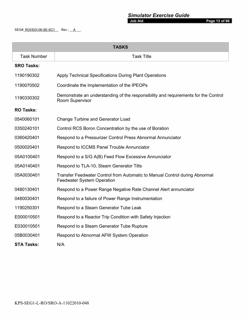
TASKS
Task Number Task Title
SRO Tasks:
1190190302 Apply Technical Specifications During Plant Operations
1190070502 Coordinate the Implementation of the IPEOPs
1190330302 Demonstrate an understanding of the responsibility and requirements for the Control Room Supervisor
RO Tasks:
0540060101 Change Turbine and Generator Load
0350240101 Control RCS Boron Concentration by the use of Boration
0360420401 Respond to a Pressurizer Control Press Abnormal Annunciator
0500020401 Respond to ICCMS Panel Trouble Annunciator
05A0100401 Respond to a S/G A(B) Feed Flow Excessive Annunciator
05A0140401 Respond to TLA-10, Steam Generator Tilts
05A0030401 Transfer Feedwater Control from Automatic to Manual Control during Abnormal Feedwater System Operation
0480130401 Respond to a Power Range Negative Rate Channel Alert annunciator
0480030401 Respond to a failure of Power Range Instrumentation
1190250301 Respond to a Steam Generator Tube Leak
E000010501 Respond to a Reactor Trip Condition with Safety Injection
E030010501 Respond to a Steam Generator Tube Rupture
05B0030401 Respond to Abnormal AFW System Operation
STA Tasks: N/A
Simulator Exercise Guide Job Aid Page 14 of 66
SEG#_ROI/SOI-06-SE-SC1__ Rev ; __A___
KPS-SEG1-L-RO/SRO-A-11022010-048
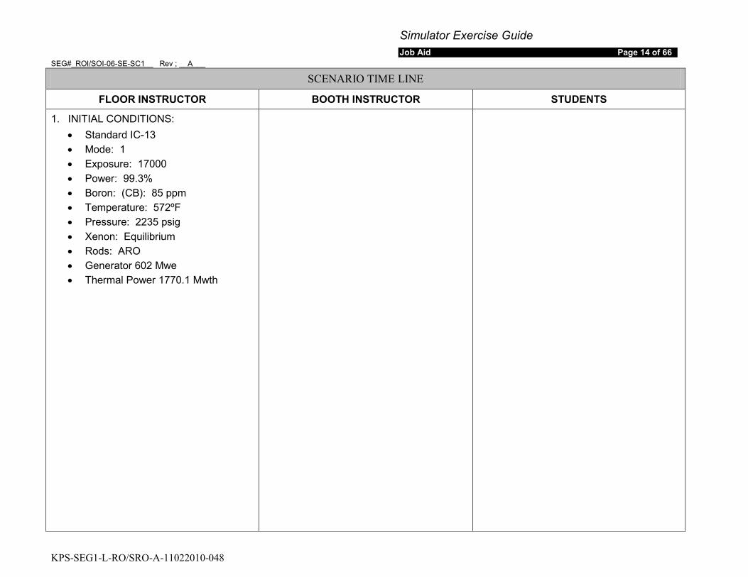
SCENARIO TIME LINE
FLOOR INSTRUCTOR BOOTH INSTRUCTOR STUDENTS
1. INITIAL CONDITIONS: • Standard IC-13 • Mode: 1 • Exposure: 17000 • Power: 99.3% • Boron: (CB): 85 ppm • Temperature: 572ºF • Pressure: 2235 psig • Xenon: Equilibrium • Rods: ARO • Generator 602 Mwe • Thermal Power 1770.1 Mwth
Simulator Exercise Guide Job Aid Page 15 of 66
SEG#_ROI/SOI-06-SE-SC1__ Rev ; __A___
KPS-SEG1-L-RO/SRO-A-11022010-048
SCENARIO TIME LINE
FLOOR INSTRUCTOR BOOTH INSTRUCTOR STUDENTS
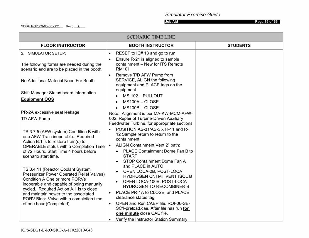
2. SIMULATOR SETUP: The following forms are needed during the scenario and are to be placed in the booth. No Additional Material Need For Booth
Shift Manager Status board information
Equipment OOS
PR-2A excessive seat leakage TD AFW Pump TS 3.7.5 (AFW system) Condition B with one AFW Train inoperable. Required Action B.1 is to restore train(s) to OPERABLE status with a Completion Time of 72 Hours. Start Time 4 hours before scenario start time. TS 3.4.11 (Reactor Coolant System Pressurizer Power Operated Relief Valves) Condition A One or more PORVs inoperable and capable of being manually cycled. Required Action A.1 is to close and maintain power to the associated PORV Block Valve with a completion time of one hour (Completed).
• RESET to IC# 13 and go to run • Ensure R-21 is aligned to sample
containment – New for ITS Remote RM101
• Remove T/D AFW Pump from SERVICE, ALIGN the following equipment and PLACE tags on the equipment • MS-102 – PULLOUT • MS100A – CLOSE • MS100B – CLOSE
Note: Alignment is per MA-KW-MCM-AFW-002, Repair of Turbine-Driven Auxiliary Feedwater Turbine, for appropriate sections • POSITION AS-31/AS-35, R-11 and R-
12 Sample return to return to the containment.
• ALIGN Containment Vent 2” path: • PLACE Containment Dome Fan B to
START • STOP Containment Dome Fan A
and PLACE in AUTO • OPEN LOCA-2B, POST-LOCA
HYDROGEN CNTMT VENT ISOL B • OPEN LOCA-100B, POST-LOCA
HYDROGEN TO RECOMBINER B • PLACE PR-1A to CLOSE, and PLACE
clearance status tag • OPEN and Run CAEP file. ROI-06-SE-
SC1-preload.cae. After file has run for one minute
• Verify the Instructor Station Summary close CAE file.
Simulator Exercise Guide Job Aid Page 16 of 66
SEG#_ROI/SOI-06-SE-SC1__ Rev ; __A___
KPS-SEG1-L-RO/SRO-A-11022010-048
SCENARIO TIME LINE
FLOOR INSTRUCTOR BOOTH INSTRUCTOR STUDENTS
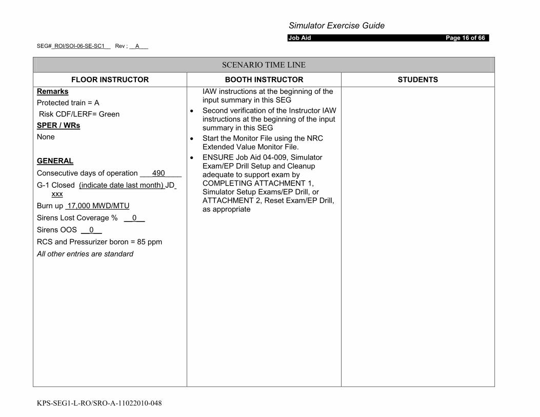
Protected train = A Remarks
Risk CDF/LERF= Green
None SPER / WRs
Consecutive days of operation ___GENERAL
490G-1 Closed
____ (indicate date last month) JD
Burn up
xxx
Sirens Lost Coverage % 17,000 MWD/MTU
Sirens OOS __0__
RCS and Pressurizer boron = 85 ppm __0__
All other entries are standard
IAW instructions at the beginning of the input summary in this SEG
• Second verification of the Instructor IAW instructions at the beginning of the input summary in this SEG
• Start the Monitor File using the NRC Extended Value Monitor File.
• ENSURE Job Aid 04-009, Simulator Exam/EP Drill Setup and Cleanup adequate to support exam by COMPLETING ATTACHMENT 1, Simulator Setup Exams/EP Drill, or ATTACHMENT 2, Reset Exam/EP Drill, as appropriate

Simulator Exercise Guide Job Aid Page 17 of 66
SEG#_ROI/SOI-06-SE-SC1__ Rev ; __A___
KPS-SEG1-L-RO/SRO-A-11022010-048
SCENARIO TIME LINE
FLOOR INSTRUCTOR BOOTH INSTRUCTOR STUDENTS
3. PRE-SCENARIO: a) IF this is the first simulator scenario
of the week, THEN
b) Provide crew with:
review the Simulator Differences List with the crew.
• Turnover sheets and plant information
• Copies of GOP-307, NOP-TB-001 (IMP IN is to be used during load reduction), NOP-HD-001, NOP-CVC-001 and Standard Reactivity Plan to support down power directed by Management
• For containment vent, Provide copy of Data Sheet C, Containment Vent Log, from SP-32-113, Gaseous Radioactive Effluents Reports For Continuous Releases, with Mont and Year filled-in, and “Date, Start Time, RP Notified (‘Y’) & Remarks (‘2” Vent’)” filled-in.
c) Cover Simulator Scenario Briefing Sheet in Job Aid 04-01 with the crew • Inform the crew that the
Designated Exam Team Member will take response for the Shift Manager. They will acknowledge communications, but their acknowledgment does not mean agreement or
Simulator Exercise Guide Job Aid Page 18 of 66
SEG#_ROI/SOI-06-SE-SC1__ Rev ; __A___
KPS-SEG1-L-RO/SRO-A-11022010-048
SCENARIO TIME LINE
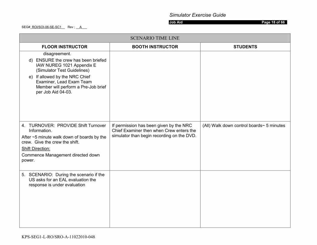
FLOOR INSTRUCTOR BOOTH INSTRUCTOR STUDENTS disagreement.
d) ENSURE the crew has been briefed IAW NUREG 1021 Appendix E (Simulator Test Guidelines)
e) If allowed by the NRC Chief Examiner, Lead Exam Team Member will perform a Pre-Job brief per Job Aid 04-03.
4. TURNOVER: PROVIDE Shift Turnover Information.
After ~5 minute walk down of boards by the crew. Give the crew the shift.
Commence Management directed down power.
Shift Direction:
If permission has been given by the NRC Chief Examiner then when Crew enters the simulator than begin recording on the DVD.
(All) Walk down control boards~ 5 minutes
5. SCENARIO: During the scenario if the US asks for an EAL evaluation the response is under evaluation
Simulator Exercise Guide Job Aid Page 19 of 66
SEG#_ROI/SOI-06-SE-SC1__ Rev ; __A___
KPS-SEG1-L-RO/SRO-A-11022010-048
SCENARIO TIME LINE
FLOOR INSTRUCTOR BOOTH INSTRUCTOR STUDENTS
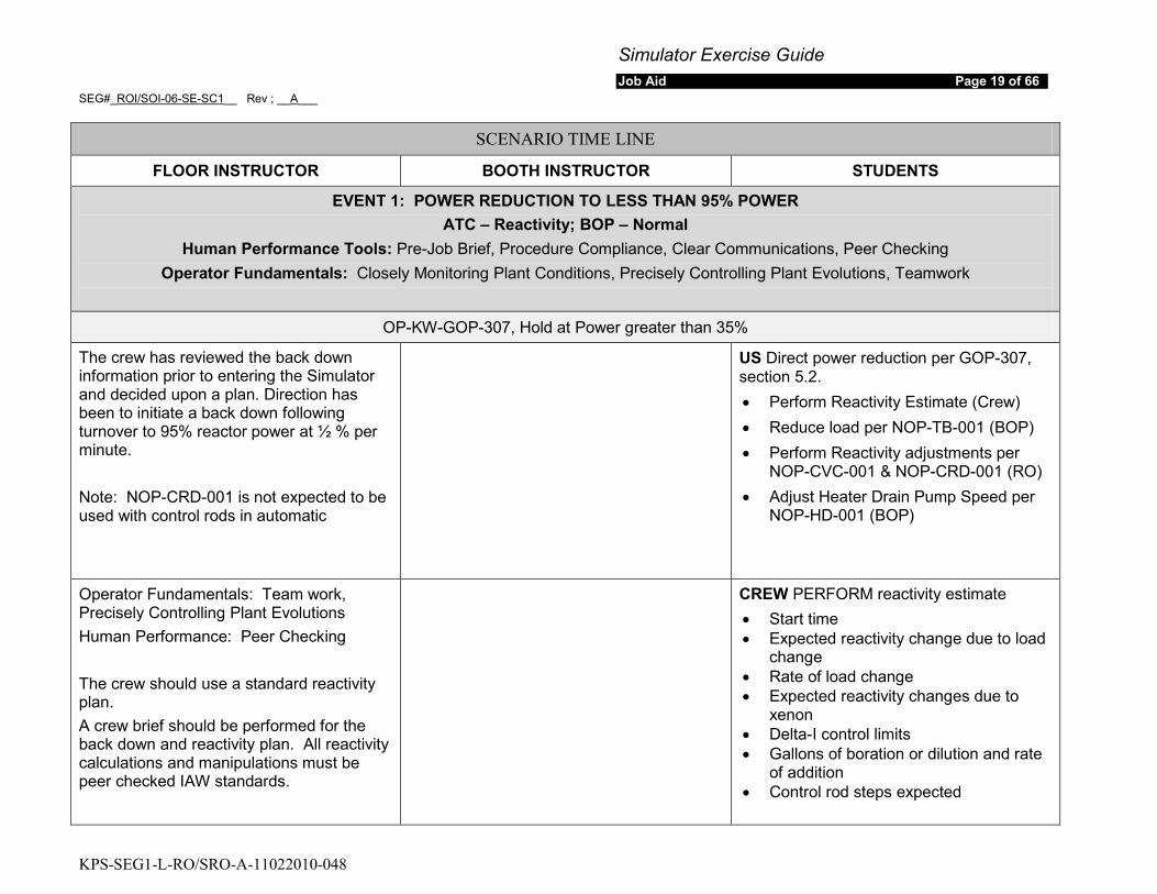
EVENT 1: POWER REDUCTION TO LESS THAN 95% POWER ATC – Reactivity; BOP – Normal
Human Performance Tools: Pre-Job Brief, Procedure Compliance, Clear Communications, Peer Checking Operator Fundamentals: Closely Monitoring Plant Conditions, Precisely Controlling Plant Evolutions, Teamwork
OP-KW-GOP-307, Hold at Power greater than 35%
The crew has reviewed the back down information prior to entering the Simulator and decided upon a plan. Direction has been to initiate a back down following turnover to 95% reactor power at ½ % per minute. Note: NOP-CRD-001 is not expected to be used with control rods in automatic
US Direct power reduction per GOP-307, section 5.2. • Perform Reactivity Estimate (Crew) • Reduce load per NOP-TB-001 (BOP) • Perform Reactivity adjustments per
NOP-CVC-001 & NOP-CRD-001 (RO) • Adjust Heater Drain Pump Speed per
NOP-HD-001 (BOP)
Operator Fundamentals: Team work, Precisely Controlling Plant Evolutions Human Performance: Peer Checking The crew should use a standard reactivity plan. A crew brief should be performed for the back down and reactivity plan. All reactivity calculations and manipulations must be peer checked IAW standards.
CREW PERFORM reactivity estimate • Start time • Expected reactivity change due to load
change • Rate of load change • Expected reactivity changes due to
xenon • Delta-I control limits • Gallons of boration or dilution and rate
of addition • Control rod steps expected
Simulator Exercise Guide Job Aid Page 20 of 66
SEG#_ROI/SOI-06-SE-SC1__ Rev ; __A___
KPS-SEG1-L-RO/SRO-A-11022010-048
SCENARIO TIME LINE
FLOOR INSTRUCTOR BOOTH INSTRUCTOR STUDENTS
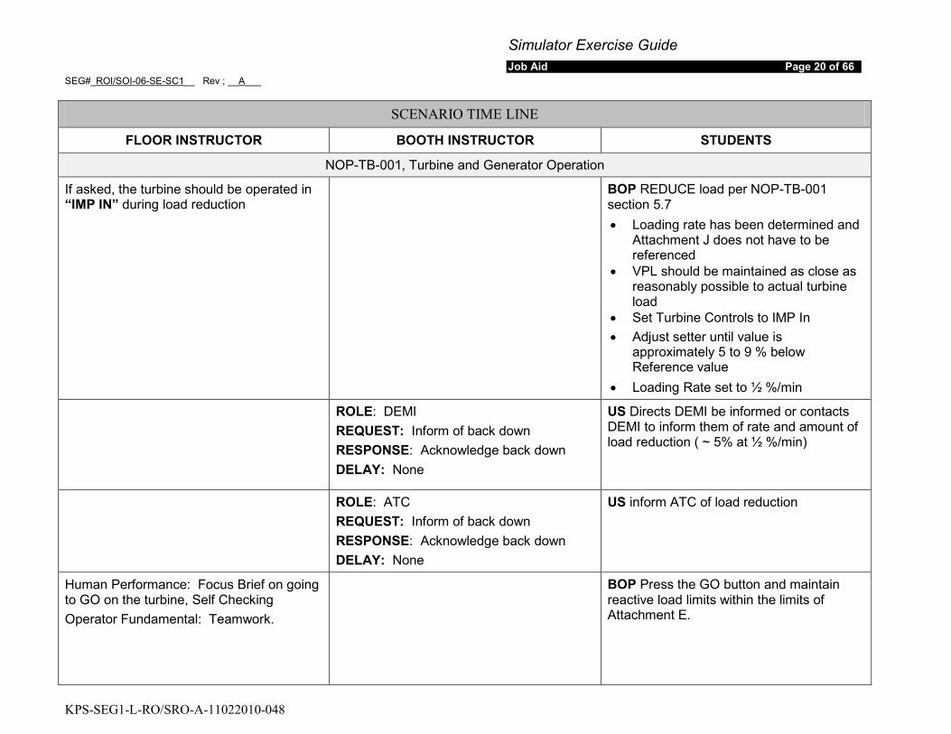
NOP-TB-001, Turbine and Generator Operation
If asked, the turbine should be operated in “IMP IN” during load reduction
BOP REDUCE load per NOP-TB-001 section 5.7 • Loading rate has been determined and
Attachment J does not have to be referenced
• VPL should be maintained as close as reasonably possible to actual turbine load
• Set Turbine Controls to IMP In • Adjust setter until value is
approximately 5 to 9 % below Reference value
• Loading Rate set to ½ %/min
ROLE: DEMI REQUEST: Inform of back down RESPONSE: Acknowledge back down DELAY: None
US Directs DEMI be informed or contacts DEMI to inform them of rate and amount of load reduction ( ~ 5% at ½ %/min)
ROLE: ATC REQUEST: Inform of back down RESPONSE: Acknowledge back down DELAY: None
US inform ATC of load reduction
Human Performance: Focus Brief on going to GO on the turbine, Self Checking Operator Fundamental: Teamwork.
BOP Press the GO button and maintain reactive load limits within the limits of Attachment E.
Simulator Exercise Guide Job Aid Page 21 of 66
SEG#_ROI/SOI-06-SE-SC1__ Rev ; __A___
KPS-SEG1-L-RO/SRO-A-11022010-048
SCENARIO TIME LINE
FLOOR INSTRUCTOR BOOTH INSTRUCTOR STUDENTS
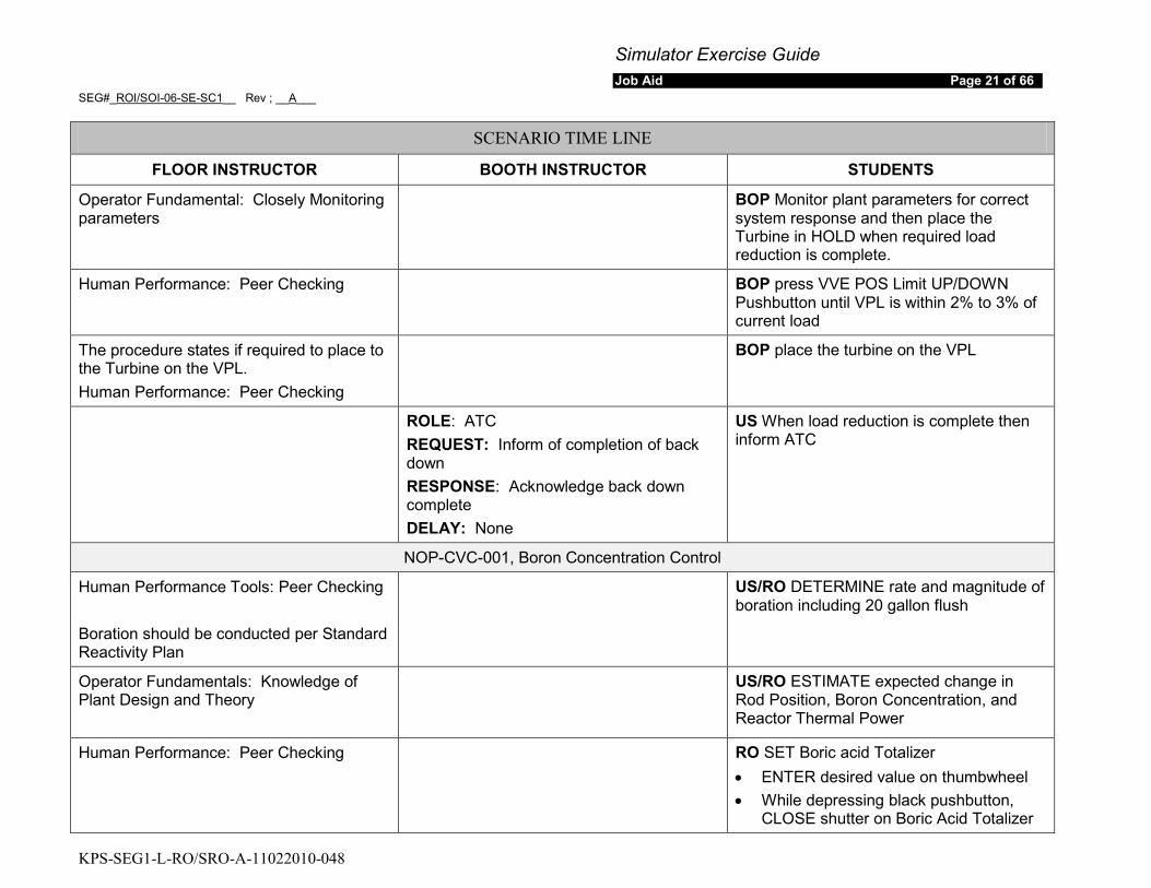
Operator Fundamental: Closely Monitoring parameters
BOP Monitor plant parameters for correct system response and then place the Turbine in HOLD when required load reduction is complete.
Human Performance: Peer Checking BOP press VVE POS Limit UP/DOWN Pushbutton until VPL is within 2% to 3% of current load
The procedure states if required to place to the Turbine on the VPL. Human Performance: Peer Checking
BOP place the turbine on the VPL
ROLE: ATC REQUEST: Inform of completion of back down RESPONSE: Acknowledge back down complete DELAY: None
US When load reduction is complete then inform ATC
NOP-CVC-001, Boron Concentration Control
Human Performance Tools: Peer Checking Boration should be conducted per Standard Reactivity Plan
US/RO DETERMINE rate and magnitude of boration including 20 gallon flush
Operator Fundamentals: Knowledge of Plant Design and Theory
US/RO ESTIMATE expected change in Rod Position, Boron Concentration, and Reactor Thermal Power
Human Performance: Peer Checking RO SET Boric acid Totalizer • ENTER desired value on thumbwheel • While depressing black pushbutton,
CLOSE shutter on Boric Acid Totalizer

Simulator Exercise Guide Job Aid Page 22 of 66
SEG#_ROI/SOI-06-SE-SC1__ Rev ; __A___
KPS-SEG1-L-RO/SRO-A-11022010-048
SCENARIO TIME LINE
FLOOR INSTRUCTOR BOOTH INSTRUCTOR STUDENTS
Human Performance: Peer Checking RO POSITION Reactor Makeup Mode Selector to BORATE
CREW should wait until boron affects Tave prior to starting the back down.
RO POSITION Reactor Makeup Control switch to START
Human Performance: Peer Checking RO ADJUST CVC-403 for BA flow rate
ROLE: AO REQUEST: Ensure CVC-712A & 712B closed RESPONSE: Acknowledge direction and report valves closed after delay DELAY: 5 minutes
RO when the boration is complete then • Ensure CVC-712A & 712B closed • Check correct quantity boric acid
added • Reset Boric Acid Totalizer
Human Performance: Peer Checking RO PERFORM 20 gpm flush • SET Rx Makeup Totalizer to 20 • POSITION Reactor Makeup Mode
Selector switch to ALT DIL
• POSITION CVC-406/CV-31094, BA Blender to VCT Control switch to CLOSE
• POSITION Reactor Makeup Control switch to START

Simulator Exercise Guide Job Aid Page 23 of 66
SEG#_ROI/SOI-06-SE-SC1__ Rev ; __A___
KPS-SEG1-L-RO/SRO-A-11022010-048
SCENARIO TIME LINE
FLOOR INSTRUCTOR BOOTH INSTRUCTOR STUDENTS The setpoint value is determined using current Boron Concentration and RD 2.1.1 OR Operator Aid 96-3 Human Performance: Peer Checking Human Performance: Self Checking
RO WHEN Alt Dilution complete: • ENSURE MU-1022 set to 60 gpm • DETERMINE setpoint for CVC-403 that
will provide blended flow at current RCS Boron Concentration
• SET CVC-403 hand controller to recorded setpoint
• POSITION CVC-406 Control switch to AUTO
• POSITION Reactor Makeup Mode Selector switch to AUTO
• POSITION Reactor Makeup Control switch to START
• At Rx Makeup Totalizer, CHECK correct quantity
• Reset Reactor MU Totalizer
NOP-HD-001, Heater Moisture Separator Drain and Bleeder Steam System
BOP ADJUST heater drain pump speed to maintain equal loading

Simulator Exercise Guide Job Aid Page 24 of 66
SEG#_ROI/SOI-06-SE-SC1__ Rev ; __A___
KPS-SEG1-L-RO/SRO-A-11022010-048
SCENARIO TIME LINE
FLOOR INSTRUCTOR BOOTH INSTRUCTOR STUDENTS
EVENT 2: Controlling Channel Pressurizer Pressure PT-431, Blue Channel, Fails High Human Performance Tools: Procedure Compliance, Clear Communications, Verification Practices
Operator Fundamentals: Closely Monitoring Plant Conditions, Knowledge of Plant Design and Theory Instrument RO
Technical Specification SRO
The controlling channel will cause the PRZR pressure control system to respond to a high Przr pressure condition:
• PRZR heaters will deenergize • PRZR Spray Valves will open • PORVs remain closed since only one
channel is affected • Actual PRZR pressure will lower
• Alarms 47041-C, 47043-C are
associated with the failed PRZR pressure channel
• 47043-D is associated with the OPERABLE PRZR pressure channels
• 47043-J is related to the depressurization resulting in rise in PRZR level
• 47044-F is related to reduced subcooling (< 20ºF) due to depressurization
When directed by the Lead Evaluator insert TRIGGER 1 Verify that RX203, PT-431 PRZ Press inserts
47041-C Pressurizer Pressure 2385 Annunciators:
47043-C Pressurizer Control Pressure Abnormal 47043-D Pressurizer Pressure Low 47043-J Charging Pump in Auto High/Low Speed 47044-F ICCMS Panel Trouble
PI-431 above 2235 psig and rising toward 2500 psig
Indications
PRZR pressure PI-429, PI-430 & PI-449 below 2235 psig and lowering PRZR heaters green lights lit PRZR Spray Valve PS-1A & PS-1B red lights light and valve demand position trending to 100% (Open)
Simulator Exercise Guide Job Aid Page 25 of 66
SEG#_ROI/SOI-06-SE-SC1__ Rev ; __A___
KPS-SEG1-L-RO/SRO-A-11022010-048
SCENARIO TIME LINE
FLOOR INSTRUCTOR BOOTH INSTRUCTOR STUDENTS
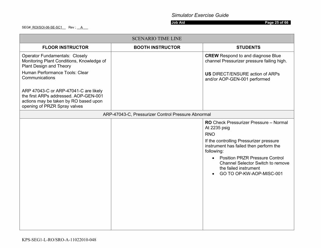
Operator Fundamentals: Closely Monitoring Plant Conditions, Knowledge of Plant Design and Theory Human Performance Tools: Clear Communications ARP 47043-C or ARP-47041-C are likely the first ARPs addressed. AOP-GEN-001 actions may be taken by RO based upon opening of PRZR Spray valves
CREW Respond to and diagnose Blue channel Pressurizer pressure failing high. US DIRECT/ENSURE action of ARPs and/or AOP-GEN-001 performed
ARP-47043-C, Pressurizer Control Pressure Abnormal
RO Check Pressurizer Pressure – Normal At 2235 psig RNO If the controlling Pressurizer pressure instrument has failed then perform the following:
• Position PRZR Pressure Control Channel Selector Switch to remove the failed instrument
• GO TO OP-KW-AOP-MISC-001
Simulator Exercise Guide Job Aid Page 26 of 66
SEG#_ROI/SOI-06-SE-SC1__ Rev ; __A___
KPS-SEG1-L-RO/SRO-A-11022010-048
SCENARIO TIME LINE
FLOOR INSTRUCTOR BOOTH INSTRUCTOR STUDENTS
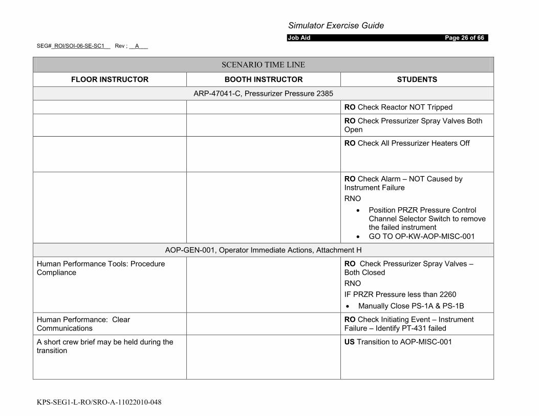
ARP-47041-C, Pressurizer Pressure 2385
RO Check Reactor NOT Tripped
RO Check Pressurizer Spray Valves Both Open
RO Check All Pressurizer Heaters Off
RO Check Alarm – NOT Caused by Instrument Failure RNO
• Position PRZR Pressure Control Channel Selector Switch to remove the failed instrument
• GO TO OP-KW-AOP-MISC-001
AOP-GEN-001, Operator Immediate Actions, Attachment H
Human Performance Tools: Procedure Compliance
RO Check Pressurizer Spray Valves – Both Closed RNO IF PRZR Pressure less than 2260 • Manually Close PS-1A & PS-1B
Human Performance: Clear Communications
RO Check Initiating Event – Instrument Failure – Identify PT-431 failed
A short crew brief may be held during the transition
US Transition to AOP-MISC-001
Simulator Exercise Guide Job Aid Page 27 of 66
SEG#_ROI/SOI-06-SE-SC1__ Rev ; __A___
KPS-SEG1-L-RO/SRO-A-11022010-048
SCENARIO TIME LINE
FLOOR INSTRUCTOR BOOTH INSTRUCTOR STUDENTS
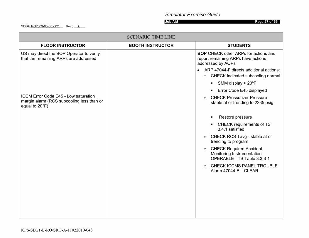
US may direct the BOP Operator to verify that the remaining ARPs are addressed ICCM Error Code E45 - Low saturation margin alarm (RCS subcooling less than or equal to 20°F)
BOP CHECK other ARPs for actions and report remaining ARPs have actions addressed by AOPs • ARP 47044-F directs additional actions:
o CHECK indicated subcooling normal
SMM display > 20ºF
Error Code E45 displayed
o CHECK Pressurizer Pressure - stable at or trending to 2235 psig
Restore pressure
CHECK requirements of TS 3.4.1 satisfied
o CHECK RCS Tavg - stable at or trending to program
o CHECK Required Accident Monitoring Instrumentation OPERABLE - TS Table 3.3.3-1
o CHECK ICCMS PANEL TROUBLE Alarm 47044-F – CLEAR
Simulator Exercise Guide Job Aid Page 28 of 66
SEG#_ROI/SOI-06-SE-SC1__ Rev ; __A___
KPS-SEG1-L-RO/SRO-A-11022010-048
SCENARIO TIME LINE
FLOOR INSTRUCTOR BOOTH INSTRUCTOR STUDENTS
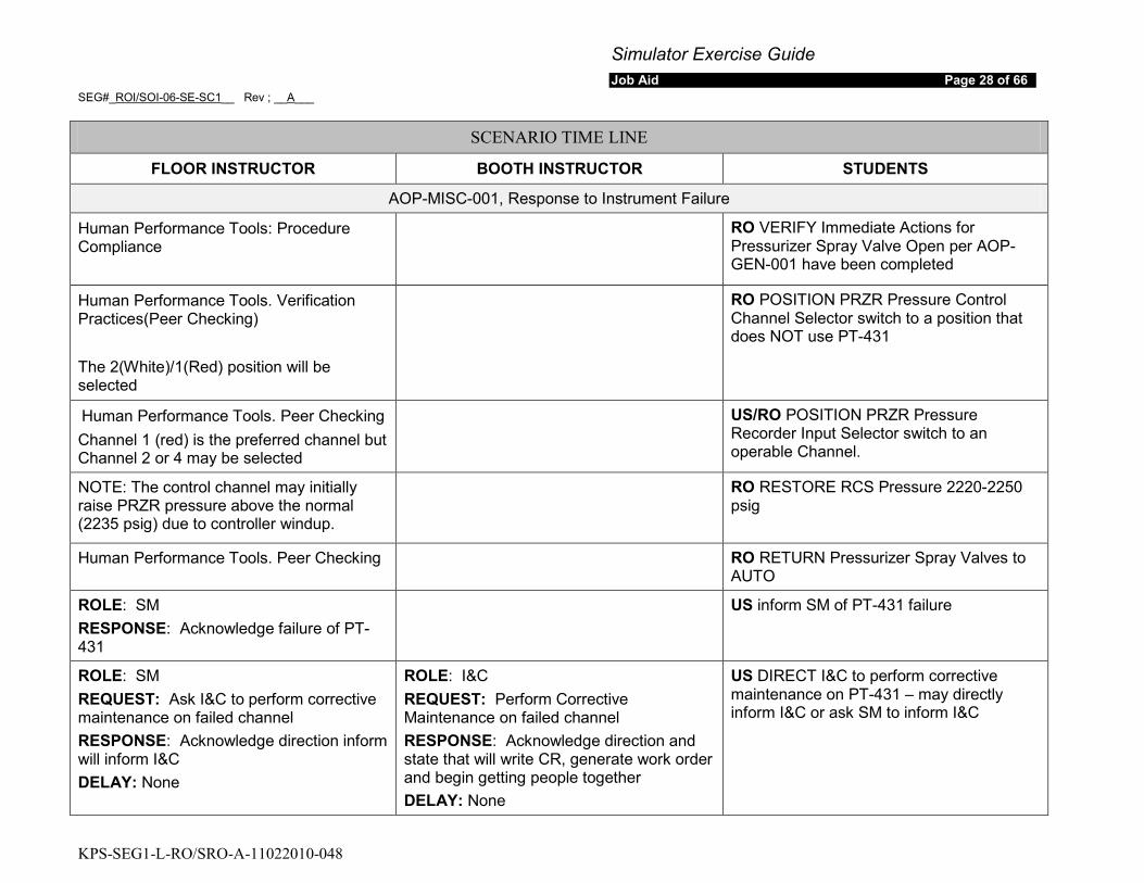
AOP-MISC-001, Response to Instrument Failure
Human Performance Tools: Procedure Compliance
RO VERIFY Immediate Actions for Pressurizer Spray Valve Open per AOP-GEN-001 have been completed
Human Performance Tools. Verification Practices(Peer Checking) The 2(White)/1(Red) position will be selected
RO POSITION PRZR Pressure Control Channel Selector switch to a position that does NOT use PT-431
Human Performance Tools. Peer Checking Channel 1 (red) is the preferred channel but Channel 2 or 4 may be selected
US/RO POSITION PRZR Pressure Recorder Input Selector switch to an operable Channel.
NOTE: The control channel may initially raise PRZR pressure above the normal (2235 psig) due to controller windup.
RO RESTORE RCS Pressure 2220-2250 psig
Human Performance Tools. Peer Checking RO RETURN Pressurizer Spray Valves to AUTO
ROLE: SM RESPONSE: Acknowledge failure of PT-431
US inform SM of PT-431 failure
ROLE: SM REQUEST: Ask I&C to perform corrective maintenance on failed channel RESPONSE: Acknowledge direction inform will inform I&C DELAY: None
ROLE: I&C REQUEST: Perform Corrective Maintenance on failed channel RESPONSE: Acknowledge direction and state that will write CR, generate work order and begin getting people together DELAY: None
US DIRECT I&C to perform corrective maintenance on PT-431 – may directly inform I&C or ask SM to inform I&C

Simulator Exercise Guide Job Aid Page 29 of 66
SEG#_ROI/SOI-06-SE-SC1__ Rev ; __A___
KPS-SEG1-L-RO/SRO-A-11022010-048
SCENARIO TIME LINE
FLOOR INSTRUCTOR BOOTH INSTRUCTOR STUDENTS
During this time it is expected that the US has a crew brief. Other than the failed PRZR pressure channel, the following conditions will be addressed in Technical Specifications: • RCS pressure, temperature and flow
DNB limits (LCO 3.4.1) depending on crew response time may have entered and exit
• PAM Instrumentation (LCO 3.3.3) - met These may be addressed later, after AOP-MISC-001 actions
US Address Technical Specifications • TS 3.3.1 (Reactor Protection
System (RPS) Instrumentation) Condition A One or more Functions with one or more required channels or trains inoperable. Required Action A.1 enter the condition referenced in Table 3.3.1-1 for the channel(s) or train(s) with a completion time of immediately.
• TS 3.3.1 (Reactor Protection System (RPS) Instrumentation) Condition E one channel inoperable with Required Action E.1 to place channel in trip with a completion time of 72 hours. Table 3.3.1-1 Item 6. Overtemperature ΔT (Loop B Chan 3 OTΔT) & item 8.b Pressurizer Pressure High.
• TS 3.3.1 (Reactor Protection System (RPS) Instrumentation) Condition K one channel inoperable with Required Action K.1 to place channel in trip with a completion time of 72 hours. Table 3.3.1-1 Item 8.a Pressurizer Pressure Low
• TS 3.3.2 Engineered Safety Feature Actuation System (ESFAS) Instrumentation Condition A One or more Functions with one or more required channels or trains inoperable. Required Action A.1 enter the condition referenced in Table 3.3.2-1 for the channel(s) or
Simulator Exercise Guide Job Aid Page 30 of 66
SEG#_ROI/SOI-06-SE-SC1__ Rev ; __A___
KPS-SEG1-L-RO/SRO-A-11022010-048
SCENARIO TIME LINE
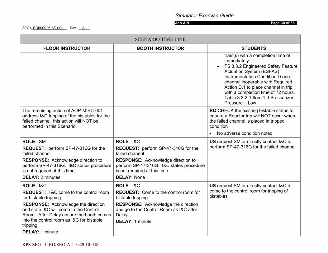
FLOOR INSTRUCTOR BOOTH INSTRUCTOR STUDENTS train(s) with a completion time of immediately.
• TS 3.3.2 Engineered Safety Feature Actuation System (ESFAS) Instrumentation Condition D one channel inoperable with Required Action D.1 to place channel in trip with a completion time of 72 hours. Table 3.3.2-1 Item 1.d Pressurizer Pressure – Low
The remaining action of AOP-MISC-001 address I&C tripping of the bistables for the failed channel, this action will NOT be performed in this Scenario.
RO CHECK the existing bistable status to ensure a Reactor trip will NOT occur when the failed channel is placed in tripped condition • No adverse condition noted
ROLE: SM REQUEST: perform SP-47-316G for the failed channel RESPONSE: Acknowledge direction to perform SP-47-316G. I&C states procedure is not required at this time. DELAY: 2 minutes
ROLE: I&C REQUEST: perform SP-47-316G for the failed channel RESPONSE: Acknowledge direction to perform SP-47-316G. I&C states procedure is not required at this time. DELAY: None
US request SM or directly contact I&C to perform SP-47-316G for the failed channel
ROLE: I&C REQUEST: I &C come to the control room for bistable tripping RESPONSE: Acknowledge the direction and state I&C will come to the Control Room. After Delay ensure the booth comes into the control room as I&C for bistable tripping DELAY: 1 minute
ROLE: I&C REQUEST: Come to the control room for bistable tripping RESPONSE: Acknowledge the direction and go to the Control Room as I&C after Delay DELAY: 1 minute
US request SM or directly contact I&C to come to the control room for tripping of bistables
Simulator Exercise Guide Job Aid Page 31 of 66
SEG#_ROI/SOI-06-SE-SC1__ Rev ; __A___
KPS-SEG1-L-RO/SRO-A-11022010-048
SCENARIO TIME LINE
FLOOR INSTRUCTOR BOOTH INSTRUCTOR STUDENTS
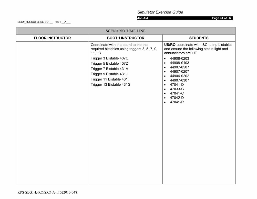
Coordinate with the board to trip the required bistables using triggers 3, 5, 7, 9, 11, 13. Trigger 3 Bistable 407C Trigger 5 Bistable 407D Trigger 7 Bistable 431A Trigger 9 Bistable 431J Trigger 11 Bistable 431I Trigger 13 Bistable 431G
US/RO coordinate with I&C to trip bistables and ensure the following status light and annunciators are LIT • 44908-0203 • 44908-0103 • 44907-0507 • 44907-0207 • 44904-0202 • 44907-0307 • 47041-D • 47033-C • 47041-C • 47042-D • 47041-R
Simulator Exercise Guide Job Aid Page 32 of 66
SEG#_ROI/SOI-06-SE-SC1__ Rev ; __A___
KPS-SEG1-L-RO/SRO-A-11022010-048
SCENARIO TIME LINE
FLOOR INSTRUCTOR BOOTH INSTRUCTOR STUDENTS
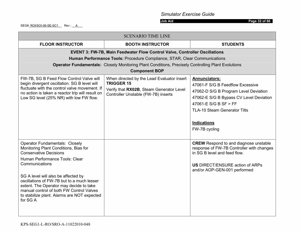
EVENT 3: FW-7B, Main Feedwater Flow Control Valve, Controller Oscillations Human Performance Tools: Procedure Compliance, STAR, Clear Communications
Operator Fundamentals: Closely Monitoring Plant Conditions, Precisely Controlling Plant Evolutions Component BOP
FW-7B, SG B Feed Flow Control Valve will begin divergent oscillation. SG B level will fluctuate with the control valve movement. If no action is taken a reactor trip will result on Low SG level (25% NR) with low FW flow.
When directed by the Lead Evaluator insert TRIGGER 15 Verify that RX02B, Steam Generator Level Controller Unstable (FW-7B) inserts
47061-F S/G B Feedflow Excessive Annunciators:
47062-D S/G B Program Level Deviation 47062-E S/G B Bypass CV Level Deviation 47061-E S/G B SF > FF TLA-10 Steam Generator Tilts
FW-7B cycling Indications
Operator Fundamentals: Closely Monitoring Plant Conditions, Bias for Conservative Decisions Human Performance Tools: Clear Communications SG A level will also be affected by oscillations of FW-7B but to a much lesser extent. The Operator may decide to take manual control of both FW Control Valves to stabilize plant. Alarms are NOT expected for SG A
CREW Respond to and diagnose unstable response of FW-7B Controller with changes in SG B level and feed flow. US DIRECT/ENSURE action of ARPs and/or AOP-GEN-001 performed
Simulator Exercise Guide Job Aid Page 33 of 66
SEG#_ROI/SOI-06-SE-SC1__ Rev ; __A___
KPS-SEG1-L-RO/SRO-A-11022010-048
SCENARIO TIME LINE
FLOOR INSTRUCTOR BOOTH INSTRUCTOR STUDENTS
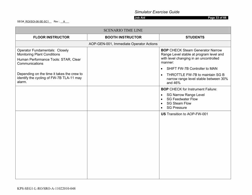
AOP-GEN-001, Immediate Operator Actions
Operator Fundamentals: Closely Monitoring Plant Conditions Human Performance Tools: STAR, Clear Communications Depending on the time it takes the crew to identify the cycling of FW-7B TLA-11 may alarm.
BOP CHECK Steam Generator Narrow Range Level stable at program level and with level changing in an uncontrolled manner:
• SHIFT FW-7B Controller to MAN
• THROTTLE FW-7B to maintain SG B narrow range level stable between 30% and 46%
BOP CHECK for Instrument Failure: • SG Narrow Range Level • SG Feedwater Flow • SG Steam Flow • SG Pressure
US Transition to AOP-FW-001
Simulator Exercise Guide Job Aid Page 34 of 66
SEG#_ROI/SOI-06-SE-SC1__ Rev ; __A___
KPS-SEG1-L-RO/SRO-A-11022010-048
SCENARIO TIME LINE
FLOOR INSTRUCTOR BOOTH INSTRUCTOR STUDENTS
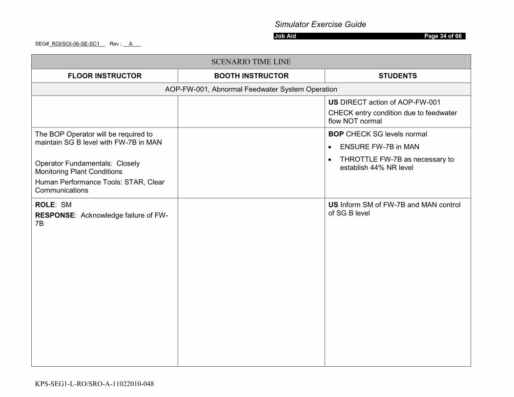
AOP-FW-001, Abnormal Feedwater System Operation
US DIRECT action of AOP-FW-001 CHECK entry condition due to feedwater flow NOT normal
The BOP Operator will be required to maintain SG B level with FW-7B in MAN Operator Fundamentals: Closely Monitoring Plant Conditions Human Performance Tools: STAR, Clear Communications
BOP CHECK SG levels normal
• ENSURE FW-7B in MAN
• THROTTLE FW-7B as necessary to establish 44% NR level
ROLE: SM RESPONSE: Acknowledge failure of FW-7B
US Inform SM of FW-7B and MAN control of SG B level
Simulator Exercise Guide Job Aid Page 35 of 66
SEG#_ROI/SOI-06-SE-SC1__ Rev ; __A___
KPS-SEG1-L-RO/SRO-A-11022010-048
SCENARIO TIME LINE
FLOOR INSTRUCTOR BOOTH INSTRUCTOR STUDENTS
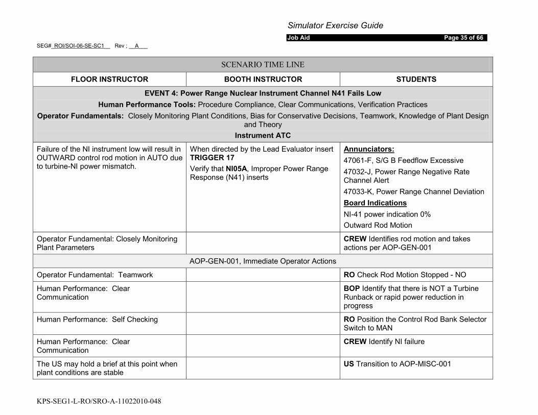
EVENT 4: Power Range Nuclear Instrument Channel N41 Fails Low Human Performance Tools: Procedure Compliance, Clear Communications, Verification Practices
Operator Fundamentals: Closely Monitoring Plant Conditions, Bias for Conservative Decisions, Teamwork, Knowledge of Plant Design and Theory
Instrument ATC
Failure of the NI instrument low will result in OUTWARD control rod motion in AUTO due to turbine-NI power mismatch.
When directed by the Lead Evaluator insert TRIGGER 17 Verify that NI05A, Improper Power Range Response (N41) inserts
47061-F, S/G B Feedflow Excessive Annunciators:
47032-J, Power Range Negative Rate Channel Alert 47033-K, Power Range Channel Deviation
NI-41 power indication 0% Board Indications
Outward Rod Motion
Operator Fundamental: Closely Monitoring Plant Parameters
CREW Identifies rod motion and takes actions per AOP-GEN-001
AOP-GEN-001, Immediate Operator Actions
Operator Fundamental: Teamwork RO Check Rod Motion Stopped - NO
Human Performance: Clear Communication
BOP Identify that there is NOT a Turbine Runback or rapid power reduction in progress
Human Performance: Self Checking RO Position the Control Rod Bank Selector Switch to MAN
Human Performance: Clear Communication
CREW Identify NI failure
The US may hold a brief at this point when plant conditions are stable
US Transition to AOP-MISC-001
Simulator Exercise Guide Job Aid Page 36 of 66
SEG#_ROI/SOI-06-SE-SC1__ Rev ; __A___
KPS-SEG1-L-RO/SRO-A-11022010-048
SCENARIO TIME LINE
FLOOR INSTRUCTOR BOOTH INSTRUCTOR STUDENTS
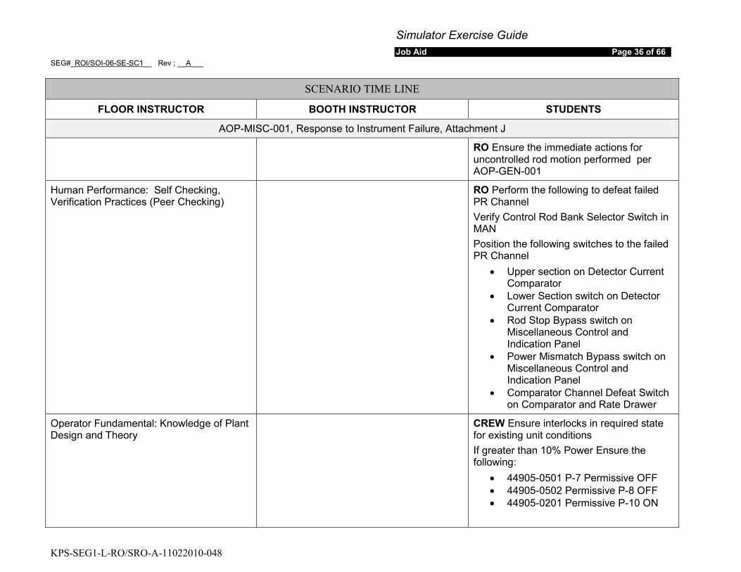
AOP-MISC-001, Response to Instrument Failure, Attachment J
RO Ensure the immediate actions for uncontrolled rod motion performed per AOP-GEN-001
Human Performance: Self Checking, Verification Practices (Peer Checking)
RO Perform the following to defeat failed PR Channel Verify Control Rod Bank Selector Switch in MAN Position the following switches to the failed PR Channel
• Upper section on Detector Current Comparator
• Lower Section switch on Detector Current Comparator
• Rod Stop Bypass switch on Miscellaneous Control and Indication Panel
• Power Mismatch Bypass switch on Miscellaneous Control and Indication Panel
• Comparator Channel Defeat Switch on Comparator and Rate Drawer
Operator Fundamental: Knowledge of Plant Design and Theory
CREW Ensure interlocks in required state for existing unit conditions If greater than 10% Power Ensure the following:
• 44905-0501 P-7 Permissive OFF • 44905-0502 Permissive P-8 OFF • 44905-0201 Permissive P-10 ON
Simulator Exercise Guide Job Aid Page 37 of 66
SEG#_ROI/SOI-06-SE-SC1__ Rev ; __A___
KPS-SEG1-L-RO/SRO-A-11022010-048
SCENARIO TIME LINE
FLOOR INSTRUCTOR BOOTH INSTRUCTOR STUDENTS
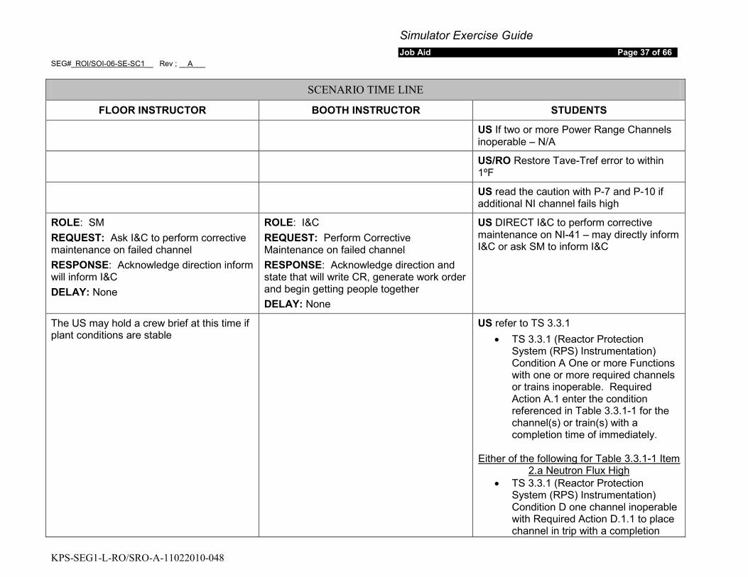
US If two or more Power Range Channels inoperable – N/A
US/RO Restore Tave-Tref error to within 1ºF
US read the caution with P-7 and P-10 if additional NI channel fails high
ROLE: SM REQUEST: Ask I&C to perform corrective maintenance on failed channel RESPONSE: Acknowledge direction inform will inform I&C DELAY: None
ROLE: I&C REQUEST: Perform Corrective Maintenance on failed channel RESPONSE: Acknowledge direction and state that will write CR, generate work order and begin getting people together DELAY: None
US DIRECT I&C to perform corrective maintenance on NI-41 – may directly inform I&C or ask SM to inform I&C
The US may hold a crew brief at this time if plant conditions are stable
US refer to TS 3.3.1 • TS 3.3.1 (Reactor Protection
System (RPS) Instrumentation) Condition A One or more Functions with one or more required channels or trains inoperable. Required Action A.1 enter the condition referenced in Table 3.3.1-1 for the channel(s) or train(s) with a completion time of immediately.
• TS 3.3.1 (Reactor Protection System (RPS) Instrumentation) Condition D one channel inoperable with Required Action D.1.1 to place channel in trip with a completion
Either of the following for Table 3.3.1-1 Item 2.a Neutron Flux High

Simulator Exercise Guide Job Aid Page 38 of 66
SEG#_ROI/SOI-06-SE-SC1__ Rev ; __A___
KPS-SEG1-L-RO/SRO-A-11022010-048
SCENARIO TIME LINE
FLOOR INSTRUCTOR BOOTH INSTRUCTOR STUDENTS time of 72 hours AND Required Action D.1.2 reduce Thermal Power to < 75% RTP with a completion time of 78 hours. Table 3.3.1-1 Item 2.a PR Neutron Flux High
OR • TS 3.3.1 (Reactor Protection
System (RPS) Instrumentation) Condition D one channel inoperable with Required Action D.2.1 to place channel in trip with a completion time of 72 hours AND Required Action D.2.2 perform SR 3.2.4.2 with a completion time of once per 12 hours. Table 3.3.1-1 Item 2.a PR Neutron Flux High
OR • TS 3.3.1 (Reactor Protection
System (RPS) Instrumentation) Condition D one channel inoperable with Required Action D.3 to be in MODE 3 with a completion time of 78 Table 3.3.1-1 Item 2.a PR Neutron Flux High
• TS 3.3.1 (Reactor Protection System (RPS) Instrumentation) Condition E one channel inoperable with Required Action E.1 to place channel in trip with a completion time of 72 hours. Table 3.3.1-1 Item 6. Overtemperature ΔT.
Either of the following for Table 3.3.1-1 Item 6 OTΔT
Simulator Exercise Guide Job Aid Page 39 of 66
SEG#_ROI/SOI-06-SE-SC1__ Rev ; __A___
KPS-SEG1-L-RO/SRO-A-11022010-048
SCENARIO TIME LINE
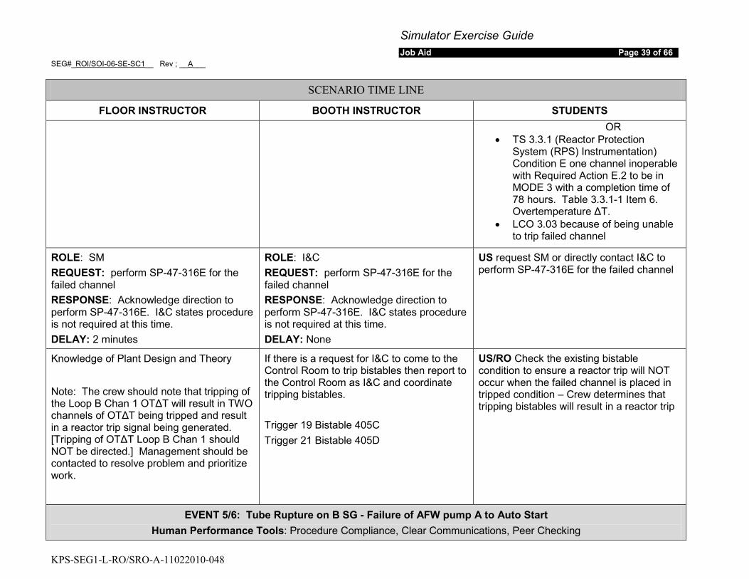
FLOOR INSTRUCTOR BOOTH INSTRUCTOR STUDENTS OR
• TS 3.3.1 (Reactor Protection System (RPS) Instrumentation) Condition E one channel inoperable with Required Action E.2 to be in MODE 3 with a completion time of 78 hours. Table 3.3.1-1 Item 6. Overtemperature ΔT.
• LCO 3.03 because of being unable to trip failed channel
ROLE: SM REQUEST: perform SP-47-316E for the failed channel RESPONSE: Acknowledge direction to perform SP-47-316E. I&C states procedure is not required at this time. DELAY: 2 minutes
ROLE: I&C REQUEST: perform SP-47-316E for the failed channel RESPONSE: Acknowledge direction to perform SP-47-316E. I&C states procedure is not required at this time. DELAY: None
US request SM or directly contact I&C to perform SP-47-316E for the failed channel
Knowledge of Plant Design and Theory
Note: The crew should note that tripping of the Loop B Chan 1 OTΔT will result in TWO channels of OTΔT being tripped and result in a reactor trip signal being generated. [Tripping of OTΔT Loop B Chan 1 should NOT be directed.] Management should be contacted to resolve problem and prioritize work.
If there is a request for I&C to come to the Control Room to trip bistables then report to the Control Room as I&C and coordinate tripping bistables. Trigger 19 Bistable 405C Trigger 21 Bistable 405D
US/RO Check the existing bistable condition to ensure a reactor trip will NOT occur when the failed channel is placed in tripped condition – Crew determines that tripping bistables will result in a reactor trip
EVENT 5/6: Tube Rupture on B SG - Failure of AFW pump A to Auto Start Human Performance Tools: Procedure Compliance, Clear Communications, Peer Checking
Simulator Exercise Guide Job Aid Page 40 of 66
SEG#_ROI/SOI-06-SE-SC1__ Rev ; __A___
KPS-SEG1-L-RO/SRO-A-11022010-048
SCENARIO TIME LINE
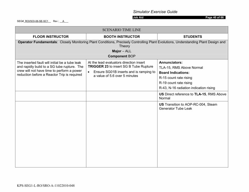
FLOOR INSTRUCTOR BOOTH INSTRUCTOR STUDENTS Operator Fundamentals: Closely Monitoring Plant Conditions, Precisely Controlling Plant Evolutions, Understanding Plant Design and
Theory Major – ALL
Component BOP
The inserted fault will initial be a tube leak and rapidly build to a SG tube rupture. The crew will not have time to perform a power reduction before a Reactor Trip is required
At the lead evaluators direction insert TRIGGER 23 to insert SG B Tube Rupture • Ensure SG01B inserts and is ramping to
a value of 5.6 over 5 minutes
Annunciators: TLA-15, RMS Above Normal Board Indications: R-15 count rate rising R-19 count rate rising R-43, N-16 radiation indication rising
US Direct reference to TLA-15, RMS Above Normal
US Transition to AOP-RC-004, Steam Generator Tube Leak
Simulator Exercise Guide Job Aid Page 41 of 66
SEG#_ROI/SOI-06-SE-SC1__ Rev ; __A___
KPS-SEG1-L-RO/SRO-A-11022010-048
SCENARIO TIME LINE
FLOOR INSTRUCTOR BOOTH INSTRUCTOR STUDENTS
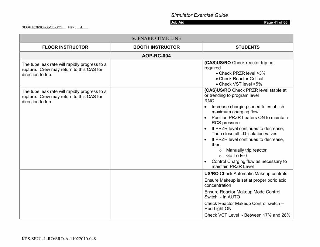
AOP-RC-004
The tube leak rate will rapidly progress to a rupture. Crew may return to this CAS for direction to trip.
(CAS)US/RO Check reactor trip not required
• Check PRZR level >3% • Check Reactor Critical • Check VST level >5%
The tube leak rate will rapidly progress to a rupture. Crew may return to this CAS for direction to trip.
(CAS)US/RO Check PRZR level stable at or trending to program level RNO • Increase charging speed to establish
maximum charging flow • Position PRZR heaters ON to maintain
RCS pressure • If PRZR level continues to decrease,
Then close all LD isolation valves • If PRZR level continues to decrease,
then: o Manually trip reactor o Go To E-0
• Control Charging flow as necessary to maintain PRZR Level
US/RO Check Automatic Makeup controls Ensure Makeup is set at proper boric acid concentration Ensure Reactor Makeup Mode Control Switch - In AUTO Check Reactor Makeup Control switch – Red Light ON Check VCT Level - Between 17% and 28%
Simulator Exercise Guide Job Aid Page 42 of 66
SEG#_ROI/SOI-06-SE-SC1__ Rev ; __A___
KPS-SEG1-L-RO/SRO-A-11022010-048
SCENARIO TIME LINE
FLOOR INSTRUCTOR BOOTH INSTRUCTOR STUDENTS
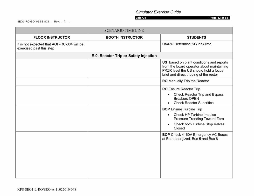
It is not expected that AOP-RC-004 will be exercised past this step
US/RO Determine SG leak rate
E-0, Reactor Trip or Safety Injection
US based on plant conditions and reports from the board operator about maintaining PRZR level the US should hold a focus brief and direct tripping of the rector
RO Manually Trip the Reactor
RO Ensure Reactor Trip • Check Reactor Trip and Bypass
Breakers OPEN • Check Reactor Subcritical
BOP Ensure Turbine Trip • Check HP Turbine Impulse
Pressure Trending Toward Zero • Check both Turbine Stop Valves
Closed
BOP Check 4160V Emergency AC Buses at Both energized. Bus 5 and Bus 6

Simulator Exercise Guide Job Aid Page 43 of 66
SEG#_ROI/SOI-06-SE-SC1__ Rev ; __A___
KPS-SEG1-L-RO/SRO-A-11022010-048
SCENARIO TIME LINE
FLOOR INSTRUCTOR BOOTH INSTRUCTOR STUDENTS
SI should have actuated, or will be required manually, on lowering PRZR level and RCS pressure.
RO Check SI actuated Check permissive status 44905-1201 SI Signal Activated LIT RNO Determine appropriate recovery action Check if SI is required
• PRZR pressure < 1815 psig • PRZR Level < 3% • RCS subcooling < 15ºF • SG pressure < 500 psig • Containment pressure > 4 psig
If SI is required then manually actuate both trains of SI
US Hold crew brief • Announce Crew Brief • EAL
o Under review • Recap Major Events
o Steam Generator Tube Rupture in B SG
• Ongoing Recovery Actions o Continue in E-0
• Comments • End Crew Brief
Crew Monitors Foldout Page
Simulator Exercise Guide Job Aid Page 44 of 66
SEG#_ROI/SOI-06-SE-SC1__ Rev ; __A___
KPS-SEG1-L-RO/SRO-A-11022010-048
SCENARIO TIME LINE
FLOOR INSTRUCTOR BOOTH INSTRUCTOR STUDENTS
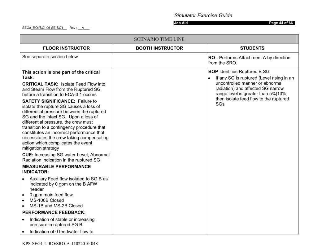
See separate section below. RO - Performs Attachment A by direction from the SRO.
This action is one part of the critical Task. CRITICAL TASK: Isolate Feed Flow into and Steam Flow from the Ruptured SG before a transition to ECA-3.1 occurs SAFETY SIGNIFICANCE: Failure to isolate the rupture SG causes a loss of differential pressure between the ruptured SG and the intact SG. Upon a loss of differential pressure, the crew must transition to a contingency procedure that constitutes an incorrect performance that necessitates the crew taking compensating action which complicates the event mitigation strategy CUE: Increasing SG water Level, Abnormal Radiation indication in the ruptured SG MEASURABLE PERFORMANCE INDICATOR: • Auxiliary Feed flow isolated to SG B as
indicated by 0 gpm on the B AFW header
• 0 gpm main feed flow • MS-100B Closed • MS-1B and MS-2B Closed PERFORMANCE FEEDBACK: • Indication of stable or increasing
pressure in ruptured SG B • Indication of 0 feedwater flow to
BOP Identifies Ruptured B SG • If any SG is ruptured (Level rising in an
uncontrolled manner or abnormal radiation) and affected SG narrow range level is greater than 5%[13%] then isolate feed flow to the ruptured SGs
Simulator Exercise Guide Job Aid Page 45 of 66
SEG#_ROI/SOI-06-SE-SC1__ Rev ; __A___
KPS-SEG1-L-RO/SRO-A-11022010-048
SCENARIO TIME LINE
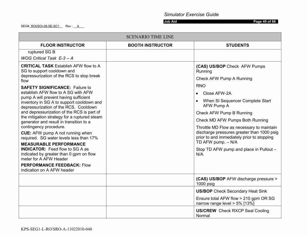
FLOOR INSTRUCTOR BOOTH INSTRUCTOR STUDENTS ruptured SG B
WOG Critical Task E-3 -- A
CRITICAL TASK Establish AFW flow to A SG to support cooldown and depressurization of the RCS to stop break flow SAFETY SIGNIFICANCE: Failure to establish AFW flow to A SG with AFW pump A will prevent having sufficient inventory in SG A to support cooldown and depressurization of the RCS. Cooldown and depressurization of the RCS is part of the mitigation strategy for a ruptured steam generator and result in transition to a contingency procedure. CUE: AFW pump A not running when required. SG water levels less than 17% MEASURABLE PERFORMANCE INDICATOR: Feed flow to SG A as indicated by greater than 0 gpm on flow meter for A AFW Header PERFORMANCE FEEDBACK: Flow indication on A AFW header
(CAS) US/BOP Check AFW Pumps Running
Check AFW Pump A Running
RNO
• Close AFW-2A
• When SI Sequencer Complete Start AFW Pump A
Check AFW Pump B Running
Check MD AFW Pumps Both Running
Throttle MD Flow as necessary to maintain discharge pressures greater than 1000 psig prior to and immediately prior to stopping TD AFW pump. – N/A
Stop TD AFW pump and place in Pullout – N/A
(CAS) US/BOP AFW discharge pressure > 1000 psig
US/BOP Check Secondary Heat Sink
Ensure total AFW flow > 210 gpm OR SG narrow range level > 5% [13%]
US/CREW Check RXCP Seal Cooling Normal
Simulator Exercise Guide Job Aid Page 46 of 66
SEG#_ROI/SOI-06-SE-SC1__ Rev ; __A___
KPS-SEG1-L-RO/SRO-A-11022010-048
SCENARIO TIME LINE
FLOOR INSTRUCTOR BOOTH INSTRUCTOR STUDENTS
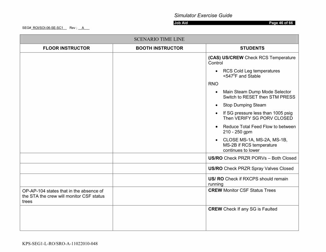
(CAS) US/CREW Check RCS Temperature Control
• RCS Cold Leg temperatures <5470
RNO
F and Stable
• Main Steam Dump Mode Selector Switch to RESET then STM PRESS
• Stop Dumping Steam
• If SG pressure less than 1005 psig Then VERIFY SG PORV CLOSED
• Reduce Total Feed Flow to between 210 - 250 gpm
• CLOSE MS-1A, MS-2A, MS-1B, MS-2B if RCS temperature continues to lower
US/RO Check PRZR PORVs – Both Closed
US/RO Check PRZR Spray Valves Closed
US/ RO Check if RXCPS should remain running
OP-AP-104 states that in the absence of the STA the crew will monitor CSF status trees
CREW Monitor CSF Status Trees
CREW Check If any SG is Faulted

Simulator Exercise Guide Job Aid Page 47 of 66
SEG#_ROI/SOI-06-SE-SC1__ Rev ; __A___
KPS-SEG1-L-RO/SRO-A-11022010-048
SCENARIO TIME LINE
FLOOR INSTRUCTOR BOOTH INSTRUCTOR STUDENTS
The US should hold a crew brief on the transition to E-3
CREW Check if SG tubes are intact • Air Ejector Exhaust Monitor Normal • SG Blowdown Liquid Monitor Normal • Main Steam Line Radiation Normal • N-16 before the trip normal • Steam Flow/Feed Flow and AG narrow
range response normal before the trip RNO DO NOT Continue until Attachment A is Complete Transition to E-3
Simulator Exercise Guide Job Aid Page 48 of 66
SEG#_ROI/SOI-06-SE-SC1__ Rev ; __A___
KPS-SEG1-L-RO/SRO-A-11022010-048
SCENARIO TIME LINE
FLOOR INSTRUCTOR BOOTH INSTRUCTOR STUDENTS
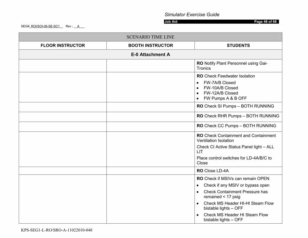
E-0 Attachment A
RO Notify Plant Personnel using Gai-Tronics
RO Check Feedwater Isolation • FW-7A/B Closed • FW-10A/B Closed • FW-12A/B Closed • FW Pumps A & B OFF
RO Check SI Pumps – BOTH RUNNING
RO Check RHR Pumps – BOTH RUNNING
RO Check CC Pumps – BOTH RUNNING
RO Check Containment and Containment Ventilation Isolation Check CI Active Status Panel light – ALL LIT Place control switches for LD-4A/B/C to Close
RO Close LD-4A
RO Check if MSIVs can remain OPEN • Check if any MSIV or bypass open • Check Containment Pressure has
remained < 17 psig • Check MS Header HI-HI Steam Flow
bistable lights – OFF • Check MS Header HI Steam Flow
bistable lights – OFF
Simulator Exercise Guide Job Aid Page 49 of 66
SEG#_ROI/SOI-06-SE-SC1__ Rev ; __A___
KPS-SEG1-L-RO/SRO-A-11022010-048
SCENARIO TIME LINE
FLOOR INSTRUCTOR BOOTH INSTRUCTOR STUDENTS
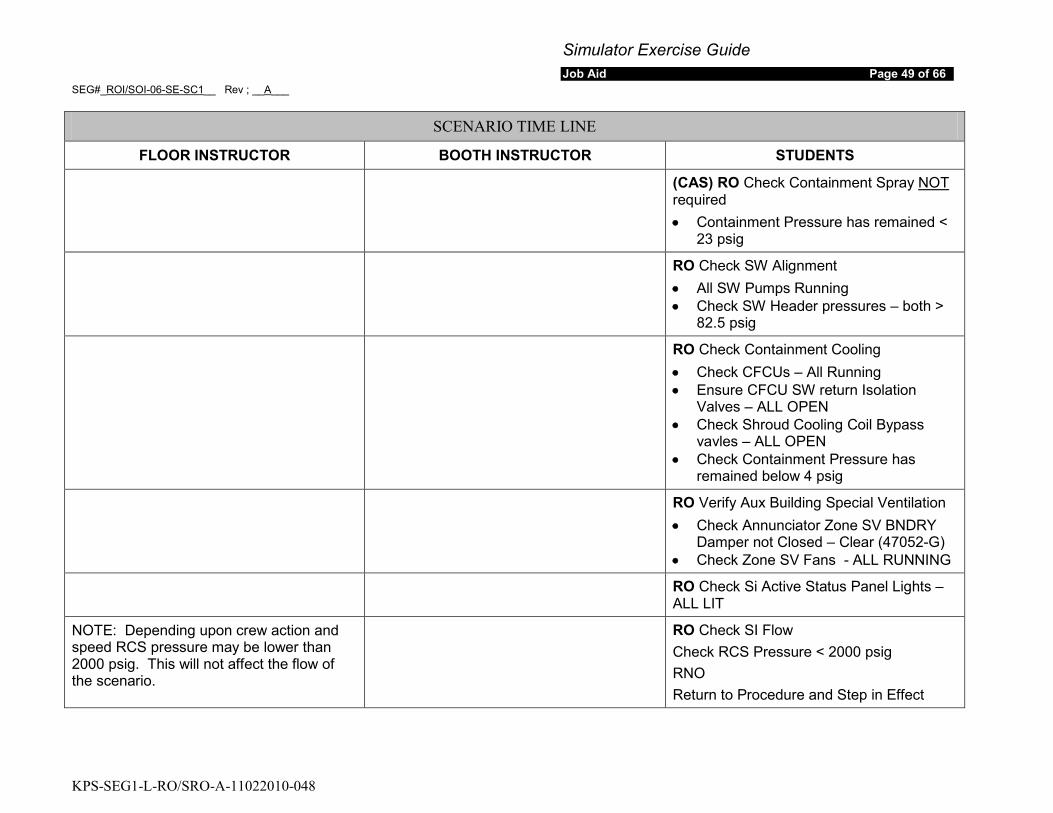
(CAS) RO Check Containment Spray NOT
• Containment Pressure has remained < 23 psig
required
RO Check SW Alignment • All SW Pumps Running • Check SW Header pressures – both >
82.5 psig
RO Check Containment Cooling • Check CFCUs – All Running • Ensure CFCU SW return Isolation
Valves – ALL OPEN • Check Shroud Cooling Coil Bypass
vavles – ALL OPEN • Check Containment Pressure has
remained below 4 psig
RO Verify Aux Building Special Ventilation • Check Annunciator Zone SV BNDRY
Damper not Closed – Clear (47052-G) • Check Zone SV Fans - ALL RUNNING
RO Check Si Active Status Panel Lights – ALL LIT
NOTE: Depending upon crew action and speed RCS pressure may be lower than 2000 psig. This will not affect the flow of the scenario.
RO Check SI Flow Check RCS Pressure < 2000 psig RNO Return to Procedure and Step in Effect
Simulator Exercise Guide Job Aid Page 50 of 66
SEG#_ROI/SOI-06-SE-SC1__ Rev ; __A___
KPS-SEG1-L-RO/SRO-A-11022010-048
SCENARIO TIME LINE
FLOOR INSTRUCTOR BOOTH INSTRUCTOR STUDENTS
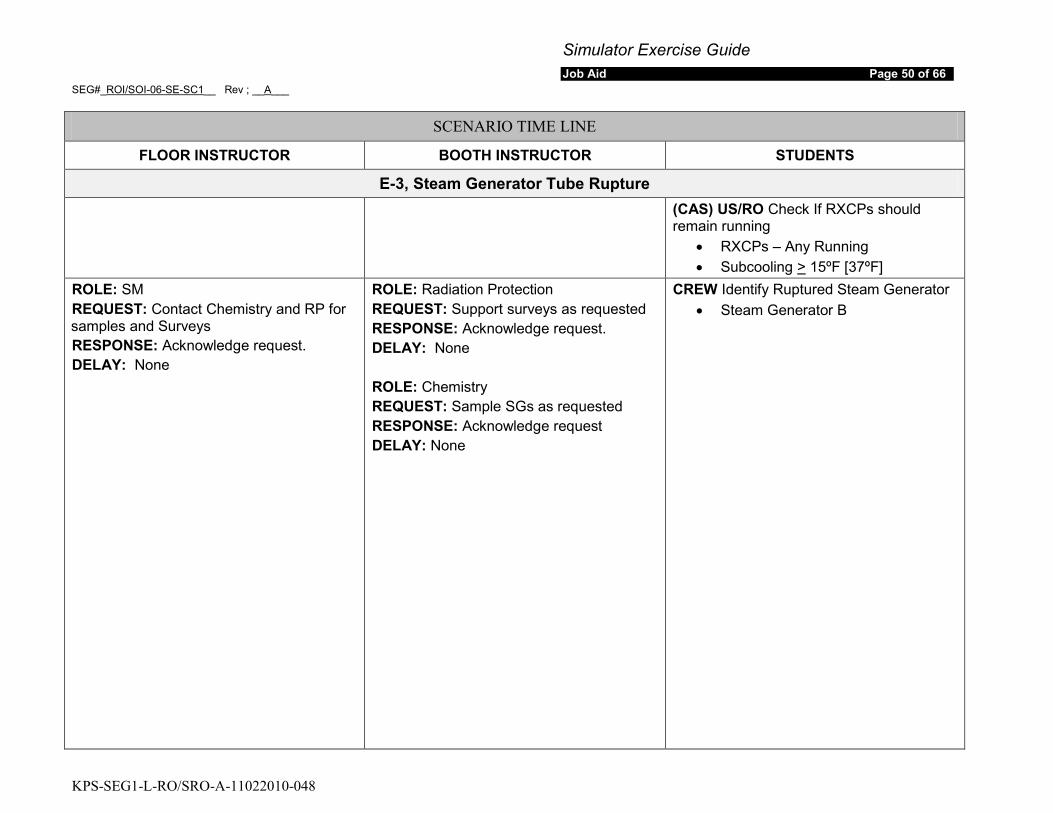
E-3, Steam Generator Tube Rupture
(CAS) US/RO Check If RXCPs should remain running
• RXCPs – Any Running • Subcooling > 15ºF [37ºF]
ROLE: SM REQUEST: Contact Chemistry and RP for samples and Surveys RESPONSE: Acknowledge request. DELAY: None
ROLE: Radiation Protection REQUEST: Support surveys as requested RESPONSE: Acknowledge request. DELAY: None ROLE: Chemistry REQUEST: Sample SGs as requested RESPONSE: Acknowledge request DELAY: None
CREW Identify Ruptured Steam Generator • Steam Generator B
Simulator Exercise Guide Job Aid Page 51 of 66
SEG#_ROI/SOI-06-SE-SC1__ Rev ; __A___
KPS-SEG1-L-RO/SRO-A-11022010-048
SCENARIO TIME LINE
FLOOR INSTRUCTOR BOOTH INSTRUCTOR STUDENTS
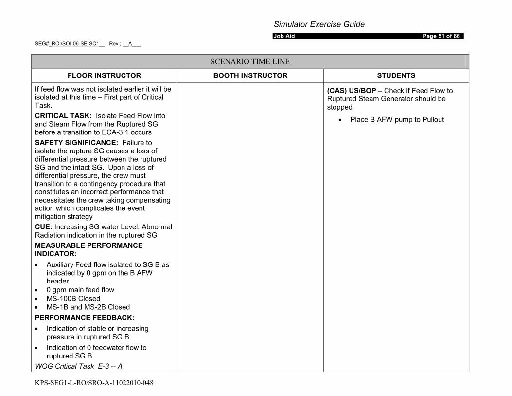
If feed flow was not isolated earlier it will be isolated at this time – First part of Critical Task. CRITICAL TASK: Isolate Feed Flow into and Steam Flow from the Ruptured SG before a transition to ECA-3.1 occurs SAFETY SIGNIFICANCE: Failure to isolate the rupture SG causes a loss of differential pressure between the ruptured SG and the intact SG. Upon a loss of differential pressure, the crew must transition to a contingency procedure that constitutes an incorrect performance that necessitates the crew taking compensating action which complicates the event mitigation strategy CUE: Increasing SG water Level, Abnormal Radiation indication in the ruptured SG MEASURABLE PERFORMANCE INDICATOR: • Auxiliary Feed flow isolated to SG B as
indicated by 0 gpm on the B AFW header
• 0 gpm main feed flow • MS-100B Closed • MS-1B and MS-2B Closed PERFORMANCE FEEDBACK: • Indication of stable or increasing
pressure in ruptured SG B • Indication of 0 feedwater flow to
ruptured SG B WOG Critical Task E-3 -- A
(CAS) US/BOP – Check if Feed Flow to Ruptured Steam Generator should be stopped
• Place B AFW pump to Pullout

Simulator Exercise Guide Job Aid Page 52 of 66
SEG#_ROI/SOI-06-SE-SC1__ Rev ; __A___
KPS-SEG1-L-RO/SRO-A-11022010-048
SCENARIO TIME LINE
FLOOR INSTRUCTOR BOOTH INSTRUCTOR STUDENTS
Isolate Steam Flow from the ruptured SG. MS-100B is already closed for maintenance – Completes the critical task CRITICAL TASK: Isolate Feed Flow into and Steam Flow from the Ruptured SG before a transition to ECA-3.1 occurs SAFETY SIGNIFICANCE: Failure to isolate the rupture SG causes a loss of differential pressure between the ruptured SG and the intact SG. Upon a loss of differential pressure, the crew must transition to a contingency procedure that constitutes an incorrect performance that necessitates the crew taking compensating action which complicates the event mitigation strategy CUE: Increasing SG water Level, Abnormal Radiation indication in the ruptured SG MEASURABLE PERFORMANCE INDICATOR: • Auxiliary Feed flow isolated to SG B as
indicated by 0 gpm on the B AFW header
• 0 gpm main feed flow • MS-100B Closed • MS-1B and MS-2B Closed PERFORMANCE FEEDBACK: • Indication of stable or increasing
pressure in ruptured SG B • Indication of 0 feedwater flow to
ruptured SG B WOG Critical Task E-3 -- A
US/BOP CLOSE Ruptured SG MSIV and Bypass Valves
Simulator Exercise Guide Job Aid Page 53 of 66
SEG#_ROI/SOI-06-SE-SC1__ Rev ; __A___
KPS-SEG1-L-RO/SRO-A-11022010-048
SCENARIO TIME LINE
FLOOR INSTRUCTOR BOOTH INSTRUCTOR STUDENTS
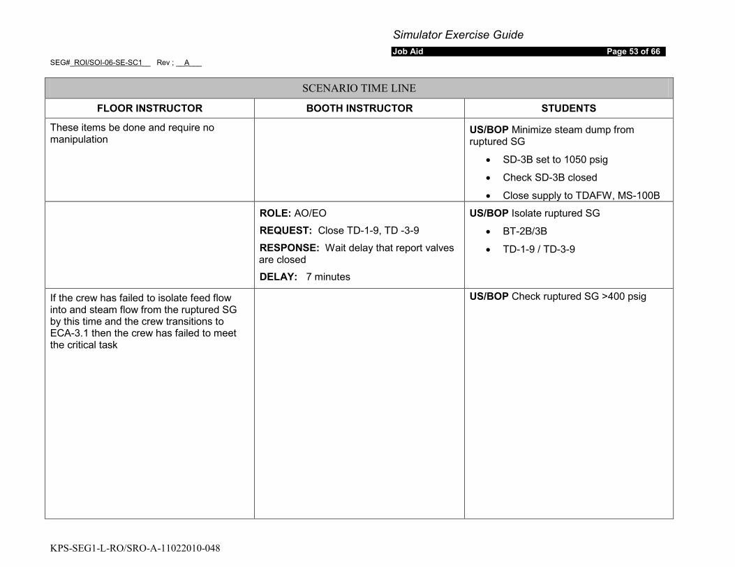
These items be done and require no manipulation
US/BOP Minimize steam dump from ruptured SG
• SD-3B set to 1050 psig
• Check SD-3B closed
• Close supply to TDAFW, MS-100B ROLE: AO/EO
REQUEST: Close TD-1-9, TD -3-9
RESPONSE: Wait delay that report valves are closed
DELAY: 7 minutes
US/BOP Isolate ruptured SG
• BT-2B/3B
• TD-1-9 / TD-3-9
If the crew has failed to isolate feed flow into and steam flow from the ruptured SG by this time and the crew transitions to ECA-3.1 then the crew has failed to meet the critical task
US/BOP Check ruptured SG >400 psig
Simulator Exercise Guide Job Aid Page 54 of 66
SEG#_ROI/SOI-06-SE-SC1__ Rev ; __A___
KPS-SEG1-L-RO/SRO-A-11022010-048
SCENARIO TIME LINE
FLOOR INSTRUCTOR BOOTH INSTRUCTOR STUDENTS
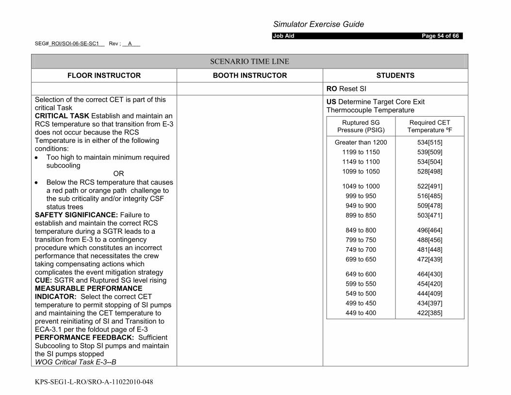
RO Reset SI Selection of the correct CET is part of this critical Task CRITICAL TASK Establish and maintain an RCS temperature so that transition from E-3 does not occur because the RCS Temperature is in either of the following conditions: • Too high to maintain minimum required
subcooling OR
• Below the RCS temperature that causes a red path or orange path challenge to the sub criticality and/or integrity CSF status trees
SAFETY SIGNIFICANCE: Failure to establish and maintain the correct RCS temperature during a SGTR leads to a transition from E-3 to a contingency procedure which constitutes an incorrect performance that necessitates the crew taking compensating actions which complicates the event mitigation strategy CUE: SGTR and Ruptured SG level rising MEASURABLE PERFORMANCE INDICATOR: Select the correct CET temperature to permit stopping of SI pumps and maintaining the CET temperature to prevent reinitiating of SI and Transition to ECA-3.1 per the foldout page of E-3 PERFORMANCE FEEDBACK: Sufficient Subcooling to Stop SI pumps and maintain the SI pumps stopped WOG Critical Task E-3--B
US Determine Target Core Exit Thermocouple Temperature
Ruptured SG Pressure (PSIG)
Required CET Temperature ºF
Greater than 1200 1199 to 1150 1149 to 1100 1099 to 1050
1049 to 1000 999 to 950 949 to 900 899 to 850
849 to 800 799 to 750 749 to 700 699 to 650
649 to 600 599 to 550 549 to 500 499 to 450 449 to 400
534[515] 539[509] 534[504] 528[498]
522[491] 516[485] 509[478] 503[471]
496[464] 488[456] 481[448] 472[439]
464[430] 454[420] 444[409] 434[397] 422[385]
Simulator Exercise Guide Job Aid Page 55 of 66
SEG#_ROI/SOI-06-SE-SC1__ Rev ; __A___
KPS-SEG1-L-RO/SRO-A-11022010-048
SCENARIO TIME LINE
FLOOR INSTRUCTOR BOOTH INSTRUCTOR STUDENTS
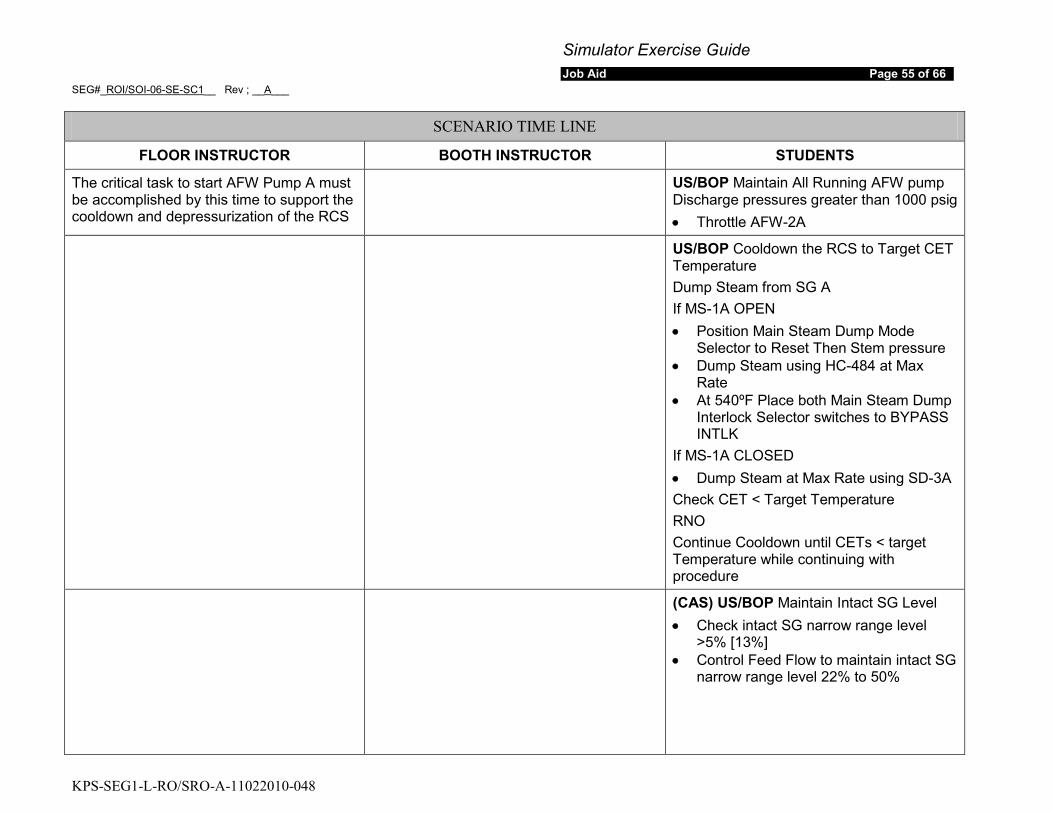
The critical task to start AFW Pump A must be accomplished by this time to support the cooldown and depressurization of the RCS
US/BOP Maintain All Running AFW pump Discharge pressures greater than 1000 psig • Throttle AFW-2A
US/BOP Cooldown the RCS to Target CET Temperature Dump Steam from SG A If MS-1A OPEN • Position Main Steam Dump Mode
Selector to Reset Then Stem pressure • Dump Steam using HC-484 at Max
Rate • At 540ºF Place both Main Steam Dump
Interlock Selector switches to BYPASS INTLK
If MS-1A CLOSED • Dump Steam at Max Rate using SD-3A Check CET < Target Temperature RNO Continue Cooldown until CETs < target Temperature while continuing with procedure
(CAS) US/BOP Maintain Intact SG Level • Check intact SG narrow range level
>5% [13%] • Control Feed Flow to maintain intact SG
narrow range level 22% to 50%

Simulator Exercise Guide Job Aid Page 56 of 66
SEG#_ROI/SOI-06-SE-SC1__ Rev ; __A___
KPS-SEG1-L-RO/SRO-A-11022010-048
SCENARIO TIME LINE
FLOOR INSTRUCTOR BOOTH INSTRUCTOR STUDENTS
(CAS) US/RO Check Pressurizer PORVs and Block Valves Available • Power Available to PRZR Block Valves • PRZR PORVs Both Closed • Check at least one PRZR Block Valve
OPEN
US/RO Reset SI
US/RO Reset Containment Isolation
US/BOP/RO Check Instrument Air Established to containment • IA-101 OPEN • Check reactor building header pressure
> 60 psig
(CAS) US/RO Check if RHR pumps should be stopped • Check if RCS pressure > 270 psig[300
psig] • Check RHR pumps not supplying
containment Sump Recirculation • Stop both RHR pumps and place in
AUTO
Simulator Exercise Guide Job Aid Page 57 of 66
SEG#_ROI/SOI-06-SE-SC1__ Rev ; __A___
KPS-SEG1-L-RO/SRO-A-11022010-048
SCENARIO TIME LINE
FLOOR INSTRUCTOR BOOTH INSTRUCTOR STUDENTS
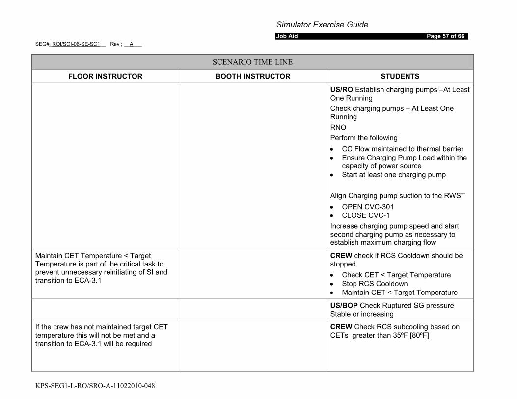
US/RO Establish charging pumps –At Least One Running Check charging pumps – At Least One Running RNO Perform the following • CC Flow maintained to thermal barrier • Ensure Charging Pump Load within the
capacity of power source • Start at least one charging pump Align Charging pump suction to the RWST • OPEN CVC-301 • CLOSE CVC-1 Increase charging pump speed and start second charging pump as necessary to establish maximum charging flow
Maintain CET Temperature < Target Temperature is part of the critical task to prevent unnecessary reinitiating of SI and transition to ECA-3.1
CREW check if RCS Cooldown should be stopped • Check CET < Target Temperature • Stop RCS Cooldown • Maintain CET < Target Temperature
US/BOP Check Ruptured SG pressure Stable or increasing
If the crew has not maintained target CET temperature this will not be met and a transition to ECA-3.1 will be required
CREW Check RCS subcooling based on CETs greater than 35ºF [80ºF]
Simulator Exercise Guide Job Aid Page 58 of 66
SEG#_ROI/SOI-06-SE-SC1__ Rev ; __A___
KPS-SEG1-L-RO/SRO-A-11022010-048
SCENARIO TIME LINE
FLOOR INSTRUCTOR BOOTH INSTRUCTOR STUDENTS
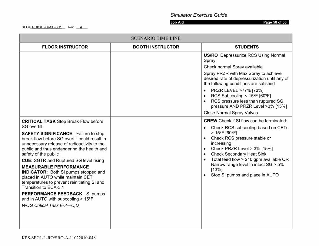
US/RO Depressurize RCS Using Normal Spray: Check normal Spray available Spray PRZR with Max Spray to achieve desired rate of depressurization until any of the following conditions are satisfied • PRZR LEVEL >77% [73%] • RCS Subcooling < 15ºF [60ºF] • RCS pressure less than ruptured SG
pressure AND PRZR Level >3% [15%] Close Normal Spray Valves
CRITICAL TASK Stop Break Flow before SG overfill SAFETY SIGNIFICANCE: Failure to stop break flow before SG overfill could result in unnecessary release of radioactivity to the public and thus endangering the health and safety of the public CUE: SGTR and Ruptured SG level rising MEASURABLE PERFORMANCE INDICATOR: Both SI pumps stopped and placed in AUTO while maintain CET temperatures to prevent reinitiating SI and Transition to ECA-3.1 PERFORMANCE FEEDBACK: SI pumps and in AUTO with subcooling > 15ºF WOG Critical Task E-3—C,D
CREW Check if SI flow can be terminated: • Check RCS subcooling based on CETs
> 15ºF [60ºF] • Check RCS pressure stable or
increasing • Check PRZR Level > 3% [15%] • Check Secondary Heat Sink • Total feed flow > 210 gpm available OR
Narrow range level in intact SG > 5% [13%]
• Stop SI pumps and place in AUTO
Simulator Exercise Guide Job Aid Page 59 of 66
SEG#_ROI/SOI-06-SE-SC1__ Rev ; __A___
KPS-SEG1-L-RO/SRO-A-11022010-048
SCENARIO TIME LINE
FLOOR INSTRUCTOR BOOTH INSTRUCTOR STUDENTS
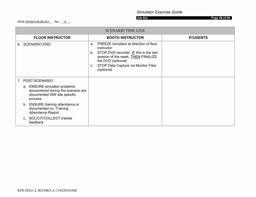
6. SCENARIO END: a. FREEZE simulator at direction of floor instructor.
b. STOP DVD recorder. IF this is the last session of the week, THEN
c. STOP Data Capture via Monitor Files (optional)
FINALIZE the DVD (optional)
7. POST-SCENARIO: a. ENSURE simulator problems
encountered during the scenario are documented IAW site specific process.
b. ENSURE training attendance is documented on, Training Attendance Report.
c. SOLICIT/COLLECT trainee feedback

Simulator Exercise Guide Job Aid Page 60 of 66
SEG#_ROI/SOI-06-SE-SC1__ Rev ; __A___
KPS-SEG1-L-RO/SRO-A-11022010-048
INPUT SUMMARY
Description Delay Time
Ramp Time
Event Trigger
Severity Or Value
Final Value
Relative Order
MALFUNCTIONS
FW16A Failure to Auto Start AFW Pump 1A 00:00:00 00:00:00 None TRUE TRUE Preload
RX201C PT-431 PRZ PRESS 00:00:00 00:00:30 1 0 2500 1
RX02B Steam Generator Level Controller Unstable (FW-7B) 00:00:00 00:15:00 15 0 75 8
NI05A Improper Power Range Channel Response (N41) 00:00:00 00:00:00 17 0 1.2 9
SG01B Steam Generator Tube Leak Inlet Tubesheet Hi-Vol 00:00:00 00:05:00 23 0 9 10
REMOTE FUNCTIONS
RM101 R-21 Alignment 00:00:00 00:00:00 None Cntmt Cntmt setup
RP141 407C-OverTemperature Trip 00:00:00 00:00:00 3 norm trip 2
RP142 407D-Rod Stop Norm 00:00:00 00:00:00 5 norm trip 3
RP164 431A-High Pressure Trip 00:00:00 00:00:00 7 norm trip 4
RP167 431J-Low Pressure Trip 00:00:00 00:00:00 9 norm trip 5
RP166 431I-Unblock SI Norm 00:00:00 00:00:00 11 norm trip 6
RP165 431G-SI Norm 00:00:00 00:00:00 13 norm trip 7
RP133 405C-Over Temperature Trip 00:00:00 00:00:00 19 norm trip cond
RP134 405D-Rod Stop Norm 00:00:00 00:00:00 21 norm trip cond
OVERRIDES
Simulator Exercise Guide Job Aid Page 61 of 66
SEG#_ROI/SOI-06-SE-SC1__ Rev ; __A___
KPS-SEG1-L-RO/SRO-A-11022010-048
INPUT SUMMARY
Description Delay Time
Ramp Time
Event Trigger
Severity Or Value
Final Value
Relative Order
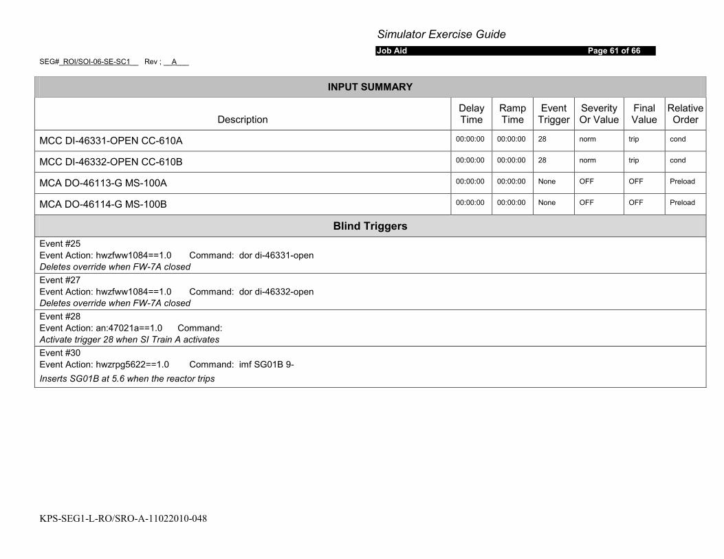
MCC DI-46331-OPEN CC-610A 00:00:00 00:00:00 28 norm trip cond
MCC DI-46332-OPEN CC-610B 00:00:00 00:00:00 28 norm trip cond
MCA DO-46113-G MS-100A 00:00:00 00:00:00 None OFF OFF Preload
MCA DO-46114-G MS-100B 00:00:00 00:00:00 None OFF OFF Preload
Blind Triggers Event #25 Event Action: hwzfww1084==1.0 Command: dor di-46331-open Deletes override when FW-7A closed Event #27 Event Action: hwzfww1084==1.0 Command: dor di-46332-open Deletes override when FW-7A closed Event #28 Event Action: an:47021a==1.0 Command: Activate trigger 28 when SI Train A activates Event #30 Event Action: hwzrpg5622==1.0 Command: imf SG01B 9- Inserts SG01B at 5.6 when the reactor trips

Simulator Exercise Guide Job Aid Page 8 of 66
SEG#_ROI/SOI-06-SE-SC1__ Rev ; __A___
KPS-SEG1-L-RO/SRO-A-11022010-048
SIMULATOR SCENARIO DEVELOPMENT CHECKLIST
Mark with an “X” Yes or No for any of the following. If the answer is No, include an explanation after the item.
Yes No
1. The scenario contains objectives for the desired tasks and relevant Human Performance Tools.
2. The scenario content adequately addresses the desired tasks, through simulator performance, instructor-led training freezes, or both.
3. Plant PRA initiating events, important equipment, and important tasks are identified.
4. Turnover information includes a Daily At Power Risk Assessment provided by the PRA Group. (PRA Validated with crew during validation)
5. The scenario contains procedurally driven success paths. Procedural discrepancies are identified and corrected before training is given.
6. The Scenario Guide includes responses for all communications to simulated personnel outside the Control Room, based on procedural guidance and standard operating practices.
7. The scenario includes related industry experience. (Not Required for Evaluations)
8. Training elements and specific Human Performance elements are addressed in the Scenario Critique Guide to be used by the Critique Facilitator. The Critique Guide includes standards for expected performance.
9. Any identified Critical Tasks possesses the following elements (NUREG-1021): • Essential to safety with adverse consequences or significant degradation, • Cue(s) prompt the Operator to respond. • Defined and measurable performance indicators. • Performance feedback.
The use of “N/A” is allowed for item 9 only if this is NOT
an evaluated scenario.
10. Technical Specifications including Limiting Conditions for Operation, reactivity briefings, and Emergency-Plan entries are addressed as appropriate.
Developer and Reviewer: Once checklist is completed and deficiencies are corrected, sign the cover page.
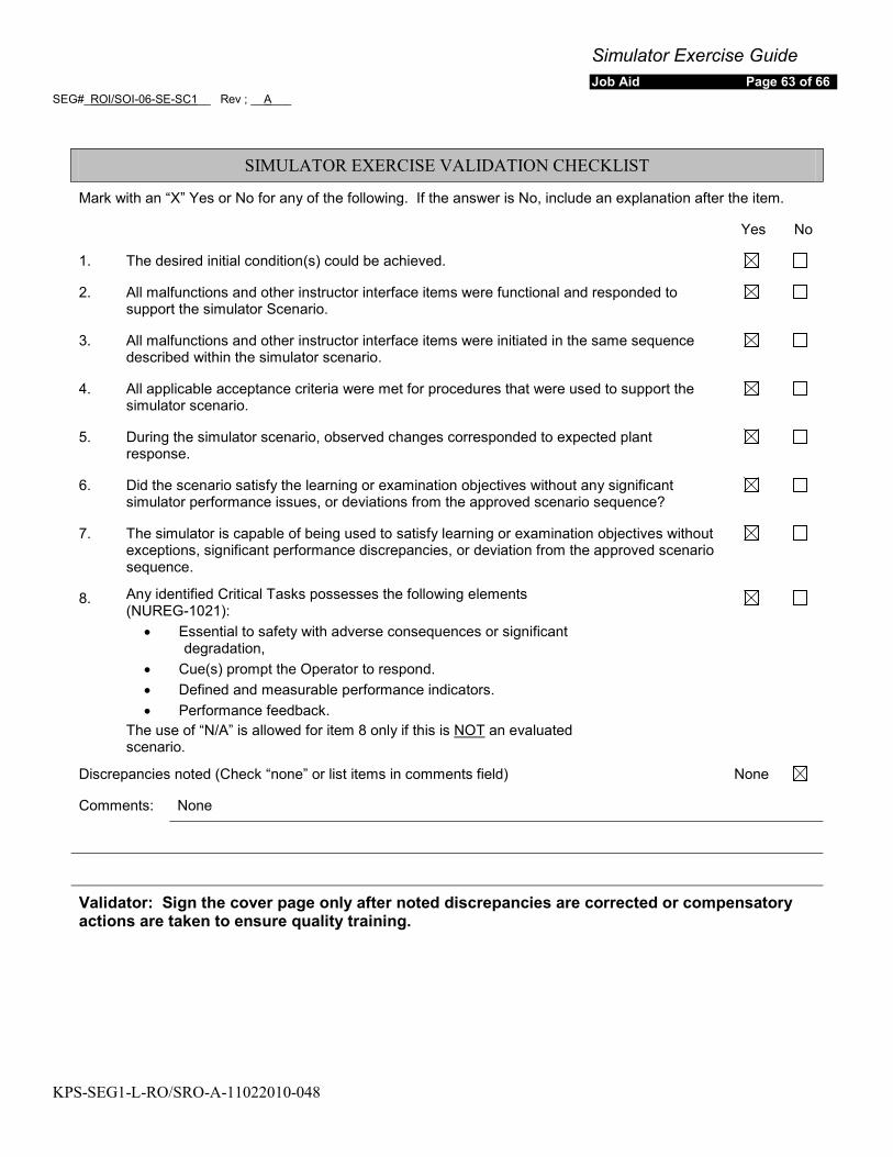
Simulator Exercise Guide Job Aid Page 63 of 66
SEG#_ROI/SOI-06-SE-SC1__ Rev ; __A___
KPS-SEG1-L-RO/SRO-A-11022010-048
SIMULATOR EXERCISE VALIDATION CHECKLIST
Mark with an “X” Yes or No for any of the following. If the answer is No, include an explanation after the item.
Yes No
1. The desired initial condition(s) could be achieved.
2. All malfunctions and other instructor interface items were functional and responded to support the simulator Scenario.
3. All malfunctions and other instructor interface items were initiated in the same sequence described within the simulator scenario.
4. All applicable acceptance criteria were met for procedures that were used to support the simulator scenario.
5. During the simulator scenario, observed changes corresponded to expected plant response.
6. Did the scenario satisfy the learning or examination objectives without any significant simulator performance issues, or deviations from the approved scenario sequence?
7. The simulator is capable of being used to satisfy learning or examination objectives without exceptions, significant performance discrepancies, or deviation from the approved scenario sequence.
8. Any identified Critical Tasks possesses the following elements (NUREG-1021):
• Essential to safety with adverse consequences or significant degradation,
• Cue(s) prompt the Operator to respond. • Defined and measurable performance indicators. • Performance feedback.
The use of “N/A” is allowed for item 8 only if this is NOT
an evaluated scenario.
Discrepancies noted (Check “none” or list items in comments field) None
Comments: None
Validator: Sign the cover page only after noted discrepancies are corrected or compensatory actions are taken to ensure quality training.
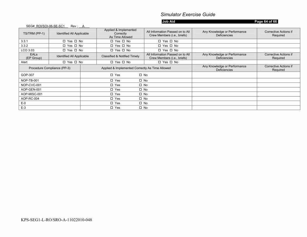
Simulator Exercise Guide Job Aid Page 64 of 66
SEG#_ROI/SOI-06-SE-SC1__ Rev ; __A___
KPS-SEG1-L-RO/SRO-A-11022010-048
TS/TRM (PP-1) Identified All Applicable Applied & Implemented
Correctly As Time Allowed
All Information Passed on to All Crew Members (i.e., briefs)
Any Knowledge or Performance Deficiencies
Corrective Actions if Required
3.3.1 Yes No Yes No Yes No 3.3.2 Yes No Yes No Yes No LCO 3.03 Yes No Yes No Yes No
EALs (EP Group) Identified All Applicable Classified & Notified Timely All Information Passed on to All
Crew Members (i.e., briefs) Any Knowledge or Performance
Deficiencies Corrective Actions if
Required Alert Yes No Yes No Yes No
Procedure Compliance (PP-3) Applied & Implemented Correctly As Time Allowed Any Knowledge or Performance Deficiencies
Corrective Actions if Required
GOP-307 Yes No
NOP-TB-001 Yes No NOP-CVC-001 Yes No AOP-GEN-001 Yes No AOP-MISC-001 Yes No AOP-RC-004 Yes No E-0 Yes No E-3 Yes No
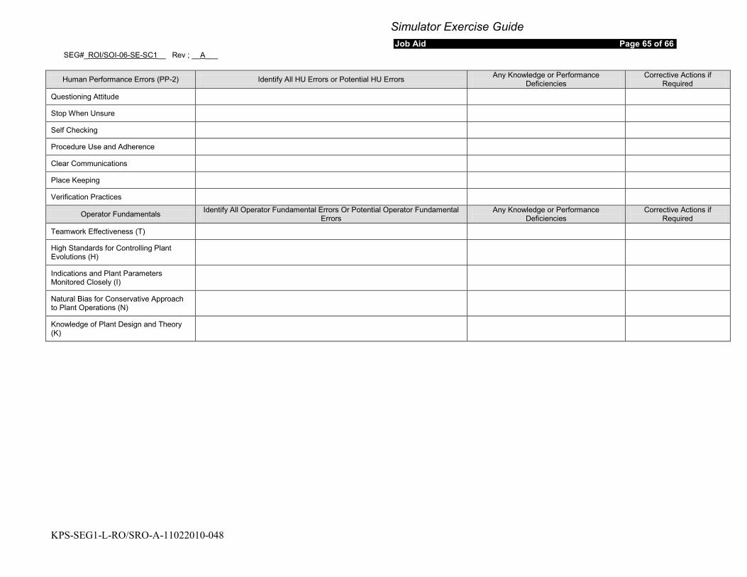
Simulator Exercise Guide Job Aid Page 65 of 66
SEG#_ROI/SOI-06-SE-SC1__ Rev ; __A___
KPS-SEG1-L-RO/SRO-A-11022010-048
Human Performance Errors (PP-2) Identify All HU Errors or Potential HU Errors Any Knowledge or Performance Deficiencies
Corrective Actions if Required
Questioning Attitude
Stop When Unsure
Self Checking
Procedure Use and Adherence
Clear Communications
Place Keeping
Verification Practices
Operator Fundamentals Identify All Operator Fundamental Errors Or Potential Operator Fundamental Errors
Any Knowledge or Performance Deficiencies
Corrective Actions if Required
Teamwork Effectiveness (T)
High Standards for Controlling Plant Evolutions (H)
Indications and Plant Parameters Monitored Closely (I)
Natural Bias for Conservative Approach to Plant Operations (N)
Knowledge of Plant Design and Theory (K)

Simulator Exercise Guide Job Aid Page 66 of 66
SEG#_ROI/SOI-06-SE-SC1__ Rev ; __A___
KPS-SEG1-L-RO/SRO-A-11022010-048
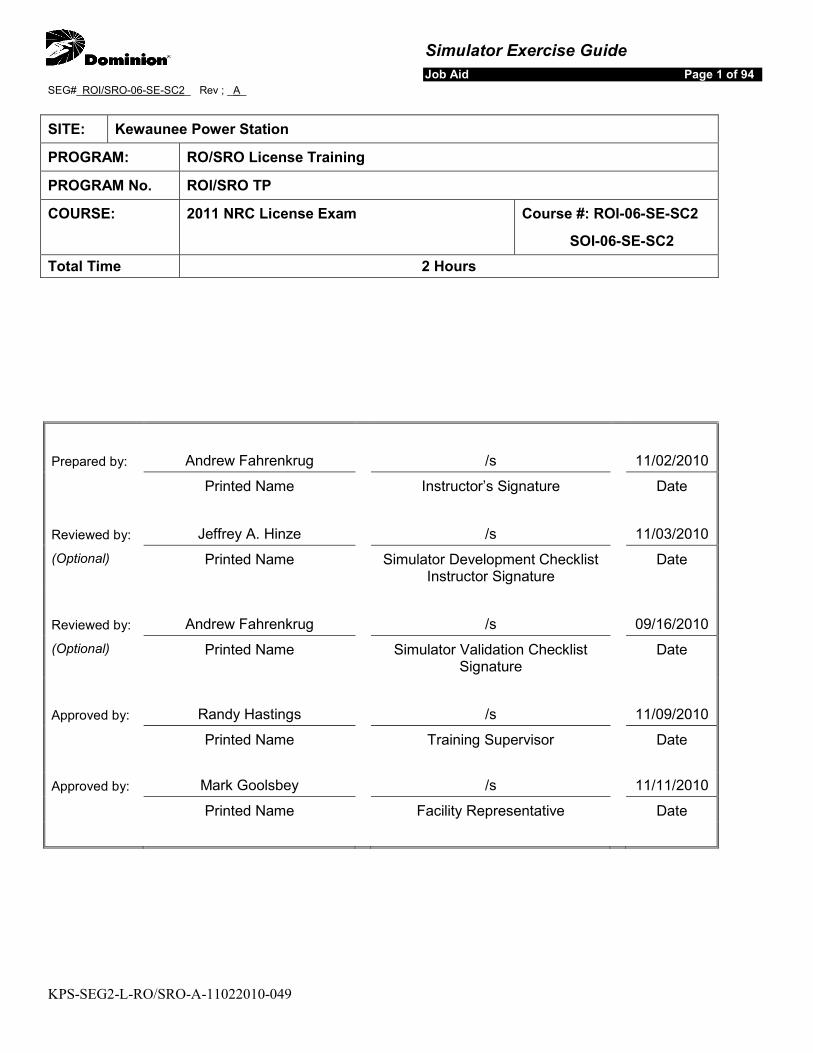
Simulator Exercise Guide Job Aid Page 1 of 94
SEG#_ROI/SRO-06-SE-SC2_ Rev ; _A_
KPS-SEG2-L-RO/SRO-A-11022010-049
SITE: Kewaunee Power Station
PROGRAM: RO/SRO License Training
PROGRAM No. ROl/SRO TP
COURSE: 2011 NRC License Exam Course #: ROI-06-SE-SC2
SOI-06-SE-SC2 Total Time 2 Hours
Prepared by: Andrew Fahrenkrug /s 11/02/2010 Printed Name Instructor’s Signature Date
Reviewed by: Jeffrey A. Hinze /s 11/03/2010 (Optional) Printed Name Simulator Development Checklist
Instructor Signature Date
Reviewed by: Andrew Fahrenkrug /s 09/16/2010 (Optional) Printed Name Simulator Validation Checklist
Signature Date
Approved by: Randy Hastings /s 11/09/2010 Printed Name Training Supervisor Date
Approved by: Mark Goolsbey /s 11/11/2010 Printed Name Facility Representative Date
Simulator Exercise Guide SEG#_ROI/SRO-06-SE-SC2_ Rev ; _A_
KPS-SEG2-L-RO/SRO-A-11022010-049
Job Aid Page 2 of 94
REQUIREMENTS
Goal of Training: Evaluate the crews response to the following events:
• Turbine Load increase
• Start a Main Feed Pump
• Reactivity manipulations
• Failure of SG ‘A’ pressure channel (PT-468 Red Channel) High
• Unisolable RCS Leak in containment to atmosphere
• Large Break LOCA
• Contingency on failure to establish containment sump recirculation
Simulator Exercise Guide SEG#_ROI/SRO-06-SE-SC2_ Rev ; _A_
KPS-SEG2-L-RO/SRO-A-11022010-049
Job Aid Page 3 of 94
Learning Objectives: While responding as the RO/BOP satisfactorily MEET the performance requirements in TR-AA-400 for the following competencies
a. Understand and Interpret Annunciator and Alarm Signals
b. Diagnose Events and Conditions based on Signals and Reading
c. Understand Plant and System Response
d. Comply with and Use Procedures and Technical Specifications
e. Operate the Control Board
f. Communicate and Interact with Other Crew Members
(RO4-06-SED01.002) ROI-06-SE-SC02.001 / SOI-06-SE-SC02.001
While responding as the US satisfactorily MEET the performance requirements in TR-AA-400 for the following competencies
a. Understand and Interpret Annunciator and Alarm Signals
b. Diagnose Events and Conditions based on Signals and Reading
c. Understand Plant and System Response
d. Comply with and Use Procedures and Technical Specifications
e. Operate the Control Board
f. Communicate and Interact with Other Crew Members
g. Direct Shift Operations
h. Comply with and Use Technical Specifications
(RO4-06-SED01.003) SOI-06-SE-SC02.002
As the US DETERMINE the appropriate event classification in accordance with EPIP-AD-02,”Emegency Classification Determination”. (This objective will be completed at the end of the scenario and may be waived at the lead evaluator’s discretion.) SOI-06-SE-SC02.003
Prerequisites: Enrolled in current ILT class and recommended by station management to take an NRC license exam.
Training Resources: Simulator
KPS Exam Team Member
NRC Examiners

Simulator Exercise Guide SEG#_ROI/SRO-06-SE-SC2_ Rev ; _A_
KPS-SEG2-L-RO/SRO-A-11022010-049
Job Aid Page 4 of 94
References: KPS Technical Specifications (ITS) KPS Technical Requirements Manual (TRM) OP-AA-100 Conduct of Operations OP-AP-104 Emergency and Abnormal Operating Procedures OP-AP-300 Reactivity Management OP-KW-GOP-106 Startup From 35% Power to Full Power NOP-RBV-002 Reactor Building Vent System Cold Operations and Making Releases NOP-TB-001 Turbine and Generator Operation NOP-FW-001 Normal Feedwater System Operation NOP-CD-001 Condensate System NOP-RCS-001 Reactor Coolant Pump Operation NOP-RCS-003 Pressurizer Pressure Control NOP-HD-001 Heater and Moisture Separator Drain and Bleeder Steam System NOP-CVC-001, Boron Concentration Control SP-32-113 Gaseous Radioactive Effluents Reports for Continuous Releases OSP-RCS-001 Reactor Coolant System Leak Rate Check AOP-GEN-001 Immediate Operator Actions AOP-MISC-001 Response to Instrument Failure AOP-MDS-002 Post Accident Leakage Control System AOP-GEN-001 Immediate Operator Actions AOP-MISC-001 Response to Instrument Failure AOP-RM-001 Abnormal Radiation Monitoring AOP-RC-001 Reactor Coolant Leak ARP 47011-B Radiation Indication High ARP-47012-B Radiation Indication Alert ARP-47023-A RWST Level Low-Low ARP-47031-P Containment Sump A Level Hi-Hi ARP-47031-Q Containment Sump A Level High ARP-47032-Q RHR Pump Pit A/B Level High ARP-47033-R Aux BLDG Flood Level High ARP-47033-35 TLA-15 RMS Above Normal ARP-47043-C Pressurizer Control Press Abnormal ARP-47043-D PRZR Pressure Low ARP-47043-E Pressurizer Level Deviation ARP-47043-F PRZR Level Low ARP-47061-A Feedwater Pump A Trip ARP-47061-C S/G A Feed Flow Excessive ARP-47061-G FWP A/B Suction Press Low ARP-47063-C Feedwater Pump A Abnormal ARP-47064-C Feedwater Pump A Vibration ARP-47065-C FWP Sea; Water DP High E-0 Reactor Trip or Safety Injection E-1 Loss of Reactor or Secondary Coolant ES-1.3 Transfer to Containment Sump Recirculation ECA-1.1 Loss of Emergency Coolant Recirculation
Simulator Exercise Guide SEG#_ROI/SRO-06-SE-SC2_ Rev ; _A_
KPS-SEG2-L-RO/SRO-A-11022010-049
Job Aid Page 5 of 94
Commitments: Per Outline submitted to NRC for 2011 Operating exam
Evaluation Method: Dynamic Simulator
Historical Record: Initial Issue
Operating Experience: Not required for evaluations
Related PRA Information:
Initiating Event with Core Damage Frequency:
Total CDF/LERF (3.6E-5/yr)/(1.6E-06/yr)
Transient with MFW Available CDF/LERF 10%/2.8%
Important Components:
System
CDF Importance Rank LERF Importance Rank
SI 8th 3 rd
CDF – Limit SI and refill RWST if sump recirculation unavailable
Important Operator Actions
LERF – Limit SI and refill RWST if sump recirculation unavailable
Simulator Exercise Guide SEG#_ROI/SRO-06-SE-SC2_ Rev ; _A_
KPS-SEG2-L-RO/SRO-A-11022010-049
Job Aid Page 6 of 94
OVERVIEW
1. Standard IC-17 51% power EOL.
INITIAL CONDITIONS:
2. 2 inch containment Vent is in progress per NOP-RBV-002 section 5.6. 3. The following equipment is OOS:
a. PR-2A seat leakage. PR-1A is closed with power maintained. b. N41 has failed low. Corrective Maintenance is in progress. All actions have been
completed per AOP-Gen-001 and AOP-Misc-001. 4. R-11/12 Sample Return is aligned to the containment.
SEQUENCE OF EVENTS:
Event 1:Crew is directed during turnover to start MFP 1A and perform a power increase to approximately 56% RTP at 1/2 %/min. The crew should start MFP 1A per NOP-FW-001. After starting MFP 1A the crew should commence the power increase using OP-KW-GOP-106.
Raise Power to 56% and start MFP A
The ATC operator will dilute in accordance with the Reactivity Plan using NOP-CVC-001, and the BOP operator will raise turbine load using NOP-TB-001.
Event 2:
This will result in indicated SG A steam flow reading higher than actual flow, and cause FW-7 A to throttle open to increase feed flow in response to the increased steam flow. Additionally, SD-3A, SG A PORV will open in response to the overpressure condition sensed by its controller.
After the power increase, SG A red channel pressure, PT-468, fails high to 1400 psig over 30 seconds
The BOP operator will respond according to AOP-GEN-001, Immediate Operator Actions, Attachment D for a SG PORV Failure, and/or the appropriate Alarm Response Procedures. Once SD-3A is noted to be open with SG A pressure less than 1005 psig, the BOP operator will manually close SD-3A by taking its controller to the MANUAL position and ensuring the control potentiometer is rotated fully clockwise to 0% demand. The operator should also take action to place FW-7A, Feed Reg Valve, in MAN, to control SG level at 30% to 46% (AOP-GEN-001, Attachment B). The failed pressure instrument will be identified and removed from service using AOP-MISC-001, Response to Instrument Failure, Attachment D Steam Generator Pressure. The alternate steam flow channel (FT-465 White) will be selected. When SG A level is stabilized FW-7A controller will be restored to Automatic. Technical Specifications:
• TS 3.3.1 (Reactor Protection System (RPS) Instrumentation) Condition A One or more Functions
Simulator Exercise Guide SEG#_ROI/SRO-06-SE-SC2_ Rev ; _A_
KPS-SEG2-L-RO/SRO-A-11022010-049
Job Aid Page 7 of 94
with one or more required channels or trains inoperable. Required Action A.1 enter the condition referenced in Table 3.3.1-1 for the channel(s) or train(s) with a completion time of immediately.
• TS 3.3.1 (Reactor Protection System (RPS) Instrumentation) Condition E one channel inoperable with Required Action E.1 to place channel in trip with a completion time of 72 hours. Table 3.3.1-1 Item 15. SG Water Level – Low coincident with Steam Flow/Feedwater Flow Mismatch.
• TS 3.3.2 Engineered Safety Feature Actuation System (ESFAS) Instrumentation Condition A One or more Functions with one or more required channels or trains inoperable. Required Action A.1 enter the condition referenced in Table 3.3.2-1 for the channel(s) or train(s) with a completion time of immediately.
• TS 3.3.2 Engineered Safety Feature Actuation System (ESFAS) Instrumentation Condition D one channel inoperable with Required Action D.1 to place channel in trip with a completion time of 72 hours. Table 3.3.2-1 Item 1.e Safety Injection - Steam Line Pressure – Low
• TS 3.3.3 Post Accident Monitoring Instrumentation all functions are met
The Unit supervisor will direct tripping of bistables. It is expected to trip bistables for the failed channel(s) during the scenario
Event 3:
The leak will reach a maximum value of approximately 20 gpm over a 2-minute period. Containment radiation monitors will indicate a marked increase in radiation levels inside containment, containment pressure and humidity level will rise, Fireworks RXCP vault detection will alarm with rising temperatures in containment. Charging Pump A in auto will increase speed to attempt to maintain PRZR level on program
After the failed SG pressure channel is addressed, a small non-isolable RCS leak will develop in containment.
The crew will respond by entering AOP-RC-001, Reactor Coolant Leak. With PRZR level lowering the crew is expected to isolate letdown and establish charging flow to maintain PRZR level on program. The crew will then attempt to diagnose and isolate the leak. The crew should determine the leak is in containment based on containment conditions. The Unit Supervisor should inform the Shift Manager (or crew member) to contact RP and set up for a containment entry to determine leak location. The Unit Supervisor will direct determining the leak rate, and based upon the value, determine that if the condition continues a unit shutdown would be required. Technical Specifications:
TS 3.4.13 RCS Operational Leakage Condition A RCS operational LEAKAGE not within limits for reasons other than pressure boundary LEAKAGE or primary to secondary LEAKAGE with Required Action A.1 to reduce leakage to within limits with a completion time of 4 hours.
Simulator Exercise Guide SEG#_ROI/SRO-06-SE-SC2_ Rev ; _A_
KPS-SEG2-L-RO/SRO-A-11022010-049
Job Aid Page 8 of 94
Event 4
RCS pressure and PRZR level will rapidly decrease. The crew is expected to recognize the need for a reactor trip and initiate Safety Injection on PRZR pressure and/or PRZR level (cannot be maintain > 3%). The reactor will trip and Safety Injection will actuate. The Containment Fan Coils Units will trip on overcurrent during the SI sequence. There is no operator action that will correct this. Tripping of Containment Fan Coil Units is done in the scenario to maintain containment pressure elevated to maintain ICS flow.
After Technical Specifications for the RCS leak have been addressed the RCS leak will develop into a large break LOCA.
The crew will perform immediate actions of E-0: 1. Verify reactor trip 2. Verify turbine trip 3. Verify Bus 5 OR Bus 6 (ESF Bus) energized 4. Check SI actuated. It is expected that SI will have been actuated, or will be required, by this time. The US will hold a brief. The US should address the FOLD OUT Page Criteria stopping RXCPs. The ATC operator will perform Attachment A steps while the US directs the BOP operator performing E-0 actions. The crew will continue the actions of E-0 to ensure Safeguards equipment is operating as required. Diagnosis will be made of a LOCA and transition will be made to E-1, Loss of Reactor Or Secondary Coolant. A RED Path is expected to exist in the Integrity CSF Status Tree. If so, entry is made into FR-P.1. When performing step 1, RCS pressure is less than 300 psig and RHR injection flow (FI-626 or FI-928) is above 700 gpm, so transition will then be made to E-1.
The crew will continue action of E-1 and monitor RWST level. When RWST level is < 37%, as indicated by annunciator 47023-B, RWST LEVEL LOW, the crew will transition to ES-1.3, Transfer To Containment Sump Recirculation.
Event 5During the performance of E-0 Attachment A by the ATC, while ensuring containment isolation will identify that CVC-211 and CVC-212 did not close. All attempted actions to close CVC-211 will fail. CVC-212 will be able to be closed from the Control Room using CVC-212 control switch on MCB.
Failure of CVC-211 and CVC-212 to CLOSE
Per Attachment A the ATC operator will manually actuate containment isolation, action will fail to close CVC-211 and CVC-212. After the failure of manual initiation of containment isolation the ATC operator will then refer to Attachment B to determine how to isolate the flow path. Options for the ATC operator are: (1) Ensure associated in isolation closed, CVC-211 is the in line isolation for CVC-212 and CVC-212 is the inline isolation for CVC-211, (2) Manually or locally close valves, CVC-211 is inside of containment and cannot be readily accessed and if the ATC operator directs the NAO to locally close CVC-212, CVC-211 inside of containment, the NAO will report the radiation levels are to high and RP will not let them enter the area. Expected the operator to close CVC-212 using the control switch on MCB. Control switch on MCB for CVC-211 will fail to work, (3) Locally close manual inline isolation, see explanation for (1) and (2).
Isolation of Containment is a Critical Task
Event 6The crew will identify Train A ECCS flow, and stop Train B and unnecessary equipment.
Failure of SI-350A and SI-350B to OPEN
The crew will attempt to open both Containment Sump B to RHR Pump Suction valves SI-350A and SI-350B at step 7 of ES-1.3. Neither valve will operate resulting in transition to ECA-1.1, Loss of Emergency Coolant Recirculation.
Simulator Exercise Guide SEG#_ROI/SRO-06-SE-SC2_ Rev ; _A_
KPS-SEG2-L-RO/SRO-A-11022010-049
Job Aid Page 9 of 94
In ECA-1.1, the BOP operator will check Containment Cooling with four Fan Coil Units in operation. The crew will determine the required number of Containment Spray Pumps required operating, stop the ICS Pumps to conserve RWST inventory. The ATC operator will be directed to initiate refill of the RWST using NOP-CVC-001. The BOP operator will continue with actions of ECA-1.1 by maintaining SG levels, initiating cooldown, if necessary, and monitoring EECS Pump operation. Actions will continue until it is determined that SI flow CANNOT be terminated (Step 17), the minimum required injection flow is determined, RHR Pumps stopped, and direction provided to adjust SI-7B locally to achieve the determined minimum flow. [THIS IS A CRITICAL TASK] The scenario may be terminated minimum injection flow has been determined.
Before EOP Entry:
Malfunctions:
1. PT-468 SG A pressure Transmitter Fails High
2. Unisolable RCS Leak
After EOP Entry:
1. SI-350A and SI-350B fail to OPEN
2. CVC-211 & CVC-212 fail to CLOSE
1. SG Pressure Transmitter Fails High
Abnormal Events:
2. RCS Leak
1. Large Break LOCA
Major Transients:
Critical Tasks
CRITICAL TASK: STOP RXCPs
a) SAFETY SIGNIFICANCE:
i) The purpose of tripping the RXCPs during LB LOCA accident conditions is to prevent pump damage and ensure RXCPs are available if needed for future recovery actions.
b) CUE:
i) RXCPs running during LB LOCA and Subcooling less than 15°F [37°F] with at least one SI pump running and capable of delivering flow, and no operator controlled cooldown in progress.
c) MEASURABLE PERFORMANCE INDICATOR:
Simulator Exercise Guide SEG#_ROI/SRO-06-SE-SC2_ Rev ; _A_
KPS-SEG2-L-RO/SRO-A-11022010-049
Job Aid Page 10 of 94
i) Crew Stops RXCPs before transitioning from E-0 per foldout page of E-0 or AOP-RC-005.
d) PERFORMANCE FEEDBACK:
i) RXCPs stopped.
CRITICAL TASK: Isolate Containment by closing CVC-212
a) SAFETY SIGNIFICANCE:
i) Failure of automatic containment isolation resulting the rise in radiation levels and exposure of personnel to radiation unnecessarily.
ii) Failure of the operator to realize the failure of containment isolation and take appropriate actions demonstrates the inability of the operator to safely and effectively operate the plant during emergency situations.
b) CUE:
i) Valid Containment Isolation signal and containment isolation valves CVC-211 and CVC-212 open
c) MEASURABLE PERFORMANCE INDICATOR:
i) Close CVC-212 prior to the transition from E-0
d) PERFORMANCE FEEDBACK:
i) CVC-212 green light Lit indicates valve close and Containment Isolation Status panel indicates CVC-212 closed
CRITICAL TASK: Direct throttling of SI-7A before RWST level reaches 4%.
a) SAFETY SIGNIFICANCE:
i) Throttling of SI-7A minimizes flow from the RWST and prolongs core cooling. The scenario is designed so that by reducing outflow from the RWST by stopping ICS pumps or one train of SI, and making up to the RWST will prevent the RWST level from lowering to < 4% prior to throttling SI-7A and prolong core cooling and minimizing core damage. The acts of minimizing outflow from the RWST and establishing makeup to the RWST are part of a critical task to maximize length of time the RWST volume is available for core cooling.
b) CUE:
i) Loss of containment sump recirculation as indicated by SI-350A and SI-350B not opening.
c) MEASURABLE PERFORMANCE INDICATOR:
i) Operator directs NAO to throttle SI-7A prior to RWST level reaching 4%.
d) PERFORMANCE FEEDBACK:
i) Response from NAO that to acknowledge throttling SI-7A.

Simulator Exercise Guide SEG#_ROI/SRO-06-SE-SC2_ Rev ; _A_
KPS-SEG2-L-RO/SRO-A-11022010-049
Job Aid Page 11 of 94
TASKS
Task Number Task Title
SRO Tasks:
1190190302 Apply Technical Specifications During Plant Operations
1190070502 Coordinate the Implementation of the IPEOPs
1190330302 Demonstrate an understanding of the responsibility and requirements for the Control Room Supervisor
RO Tasks:
0540060101 Change Turbine and Generator Load
0350240101 Control RCS Boron Concentration by the use of Boration
0060000001 Operate the Steam Generator and Steam Generator Water Level Control System and its components during any mode of operation
03600030401 Respond to an unidentified RCS leak
E010050501 Respond to a loss of Emergency Coolant Recirculation
STA Tasks: N/A
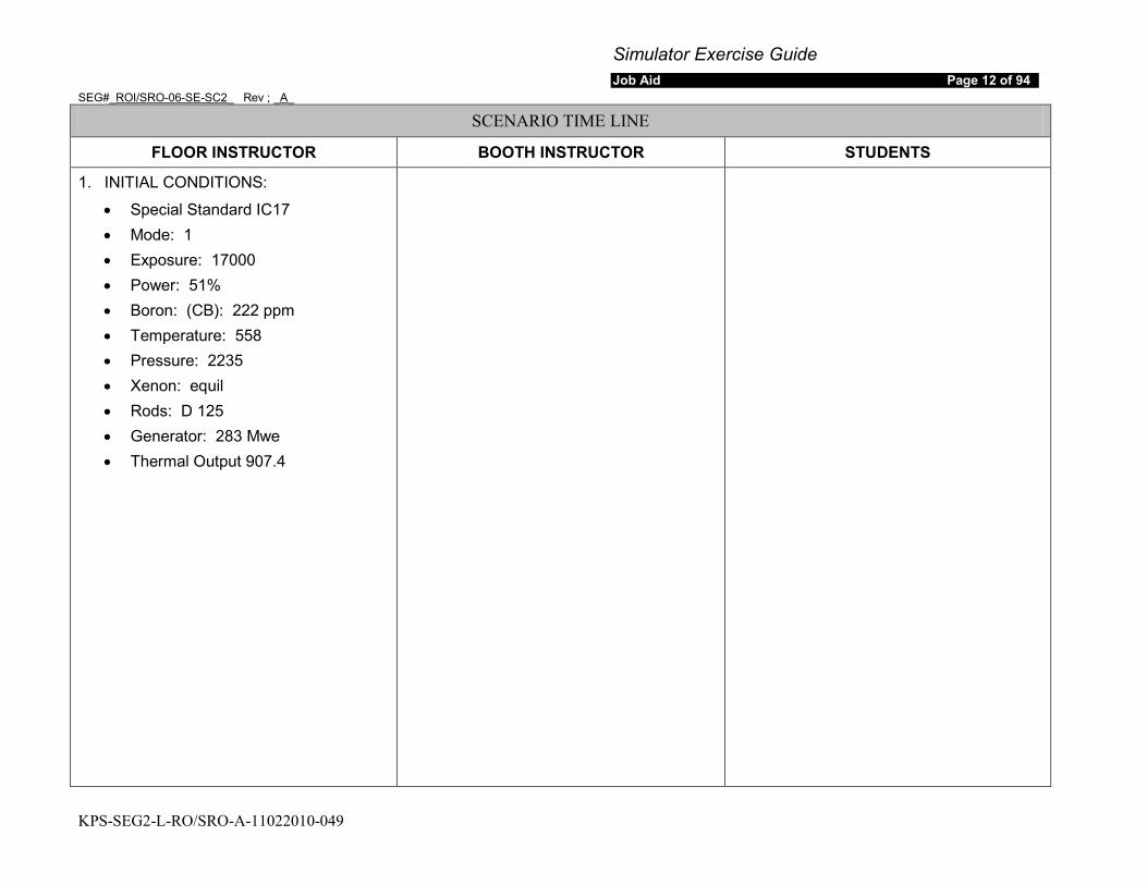
Simulator Exercise Guide Job Aid Page 12 of 94
SEG#_ROI/SRO-06-SE-SC2_ Rev ; _A_
KPS-SEG2-L-RO/SRO-A-11022010-049
SCENARIO TIME LINE
FLOOR INSTRUCTOR BOOTH INSTRUCTOR STUDENTS
1. INITIAL CONDITIONS:
• Special Standard IC17 • Mode: 1 • Exposure: 17000 • Power: 51% • Boron: (CB): 222 ppm • Temperature: 558 • Pressure: 2235 • Xenon: equil • Rods: D 125 • Generator: 283 Mwe • Thermal Output 907.4
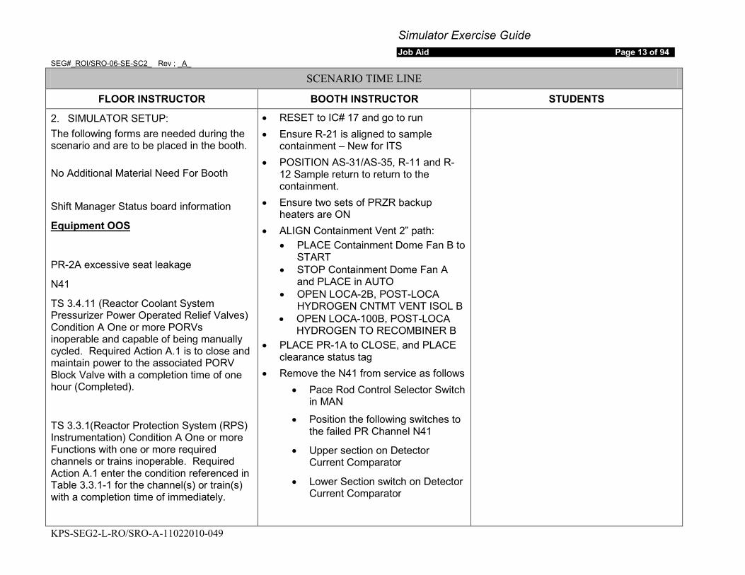
Simulator Exercise Guide Job Aid Page 13 of 94
SEG#_ROI/SRO-06-SE-SC2_ Rev ; _A_
KPS-SEG2-L-RO/SRO-A-11022010-049
SCENARIO TIME LINE
FLOOR INSTRUCTOR BOOTH INSTRUCTOR STUDENTS
2. SIMULATOR SETUP: The following forms are needed during the scenario and are to be placed in the booth. No Additional Material Need For Booth
Shift Manager Status board information
Equipment OOS
PR-2A excessive seat leakage
N41
TS 3.4.11 (Reactor Coolant System Pressurizer Power Operated Relief Valves) Condition A One or more PORVs inoperable and capable of being manually cycled. Required Action A.1 is to close and maintain power to the associated PORV Block Valve with a completion time of one hour (Completed).
TS 3.3.1(Reactor Protection System (RPS) Instrumentation) Condition A One or more Functions with one or more required channels or trains inoperable. Required Action A.1 enter the condition referenced in Table 3.3.1-1 for the channel(s) or train(s) with a completion time of immediately.
• RESET to IC# 17 and go to run • Ensure R-21 is aligned to sample
containment – New for ITS • POSITION AS-31/AS-35, R-11 and R-
12 Sample return to return to the containment.
• Ensure two sets of PRZR backup heaters are ON
• ALIGN Containment Vent 2” path: • PLACE Containment Dome Fan B to
START • STOP Containment Dome Fan A
and PLACE in AUTO • OPEN LOCA-2B, POST-LOCA
HYDROGEN CNTMT VENT ISOL B • OPEN LOCA-100B, POST-LOCA
HYDROGEN TO RECOMBINER B • PLACE PR-1A to CLOSE, and PLACE
clearance status tag • Remove the N41 from service as follows
• Pace Rod Control Selector Switch in MAN
• Position the following switches to the failed PR Channel N41
• Upper section on Detector Current Comparator
• Lower Section switch on Detector Current Comparator
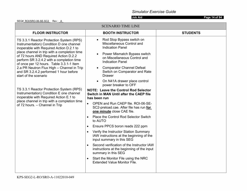
Simulator Exercise Guide Job Aid Page 14 of 94
SEG#_ROI/SRO-06-SE-SC2_ Rev ; _A_
KPS-SEG2-L-RO/SRO-A-11022010-049
SCENARIO TIME LINE
FLOOR INSTRUCTOR BOOTH INSTRUCTOR STUDENTS
TS 3.3.1 Reactor Protection System (RPS) Instrumentation) Condition D one channel inoperable with Required Action D.2.1 to place channel in trip with a completion time of 72 hours AND Required Action D.2.2 perform SR 3.2.4.2 with a completion time of once per 12 hours. Table 3.3.1-1 Item 2.a PR Neutron Flux High – Channel in Trip and SR 3.2.4.2 performed 1 hour before start of the scenario
TS 3.3.1 Reactor Protection System (RPS) Instrumentation) Condition E one channel inoperable with Required Action E.1 to place channel in trip with a completion time of 72 hours. – Channel in Trip
• Rod Stop Bypass switch on Miscellaneous Control and Indication Panel
• Power Mismatch Bypass switch on Miscellaneous Control and Indication Panel
• Comparator Channel Defeat Switch on Comparator and Rate Drawer
• On N41A drawer place control power breaker to OFF
NOTE: Leave the Control Rod Selector Switch in MAN Until after the CAEP file has been run • OPEN and Run CAEP file. ROI-06-SE-
SC2-preload.cae. After file has run for one minute
• Place the Control Rod Selector Switch to AUTO
close CAE file.
• Ensure PPCS boron reads 222 ppm • Verify the Instructor Station Summary
IAW instructions at the beginning of the input summary in this SEG
• Second verification of the Instructor IAW instructions at the beginning of the input summary in this SEG
• Start the Monitor File using the NRC Extended Value Monitor File.
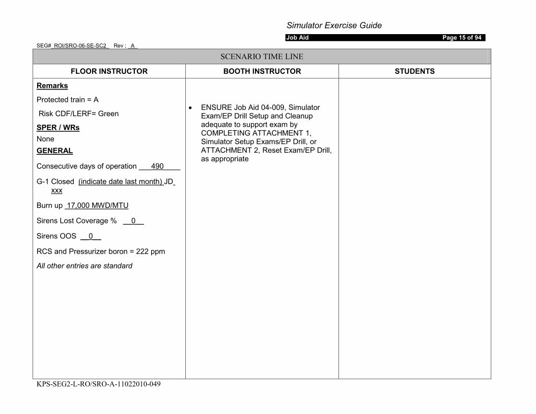
Simulator Exercise Guide Job Aid Page 15 of 94
SEG#_ROI/SRO-06-SE-SC2_ Rev ; _A_
KPS-SEG2-L-RO/SRO-A-11022010-049
SCENARIO TIME LINE
FLOOR INSTRUCTOR BOOTH INSTRUCTOR STUDENTS
Protected train = A
Remarks
Risk CDF/LERF= Green
None SPER / WRs
Consecutive days of operation ___
GENERAL
490
G-1 Closed
____
(indicate date last month) JD
Burn up
xxx
Sirens Lost Coverage %
17,000 MWD/MTU
Sirens OOS
__0__
RCS and Pressurizer boron = 222 ppm
__0__
All other entries are standard
• ENSURE Job Aid 04-009, Simulator
Exam/EP Drill Setup and Cleanup adequate to support exam by COMPLETING ATTACHMENT 1, Simulator Setup Exams/EP Drill, or ATTACHMENT 2, Reset Exam/EP Drill, as appropriate

Simulator Exercise Guide Job Aid Page 16 of 94
SEG#_ROI/SRO-06-SE-SC2_ Rev ; _A_
KPS-SEG2-L-RO/SRO-A-11022010-049
SCENARIO TIME LINE
FLOOR INSTRUCTOR BOOTH INSTRUCTOR STUDENTS
3. PRE-SCENARIO:
a) IF this is the first simulator scenario of the week, THEN
b) Provide crew with:
review the Simulator Differences List with the crew.
• Turnover sheets and plant information
• Plant Brief for GOP-106 – To be given if asked for
• Brief for startup of second main Feed Pump – to be given if asked for
• Copies of the following procedures: • GOP-106 completed up to
and including section 5.1.12, • NOP-FW-001 completed up
to and including step 5.1.5 • NOP-TB-001 • NOP-HD-001, • NOP-CVC-001 • Reactivity Plan to support
power change • For containment vent,
Provide copy of Data Sheet C, Containment Vent Log, from SP-32-113, Gaseous Radioactive Effluents Reports For Continuous Releases, with Mont and Year filled-in, and “Date,
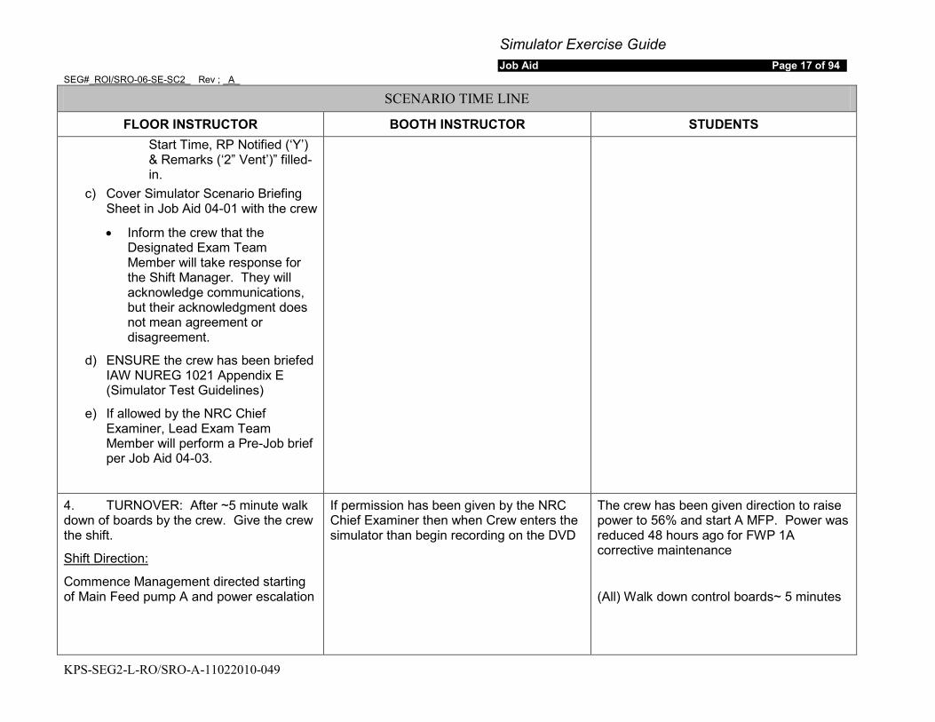
Simulator Exercise Guide Job Aid Page 17 of 94
SEG#_ROI/SRO-06-SE-SC2_ Rev ; _A_
KPS-SEG2-L-RO/SRO-A-11022010-049
SCENARIO TIME LINE
FLOOR INSTRUCTOR BOOTH INSTRUCTOR STUDENTS Start Time, RP Notified (‘Y’) & Remarks (‘2” Vent’)” filled-in.
c) Cover Simulator Scenario Briefing Sheet in Job Aid 04-01 with the crew
• Inform the crew that the Designated Exam Team Member will take response for the Shift Manager. They will acknowledge communications, but their acknowledgment does not mean agreement or disagreement.
d) ENSURE the crew has been briefed IAW NUREG 1021 Appendix E (Simulator Test Guidelines)
e) If allowed by the NRC Chief Examiner, Lead Exam Team Member will perform a Pre-Job brief per Job Aid 04-03.
4. TURNOVER: After ~5 minute walk down of boards by the crew. Give the crew the shift.
Commence Management directed starting of Main Feed pump A and power escalation
Shift Direction:
If permission has been given by the NRC Chief Examiner then when Crew enters the simulator than begin recording on the DVD
The crew has been given direction to raise power to 56% and start A MFP. Power was reduced 48 hours ago for FWP 1A corrective maintenance
(All) Walk down control boards~ 5 minutes
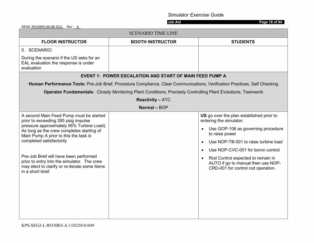
Simulator Exercise Guide Job Aid Page 18 of 94
SEG#_ROI/SRO-06-SE-SC2_ Rev ; _A_
KPS-SEG2-L-RO/SRO-A-11022010-049
SCENARIO TIME LINE
FLOOR INSTRUCTOR BOOTH INSTRUCTOR STUDENTS
5. SCENARIO:
During the scenario if the US asks for an EAL evaluation the response is under evaluation
EVENT 1: POWER ESCALATION AND START OF MAIN FEED PUMP A
Human Performance Tools: Pre-Job Brief, Procedure Compliance, Clear Communications, Verification Practices, Self Checking
Operator Fundamentals: Closely Monitoring Plant Conditions, Precisely Controlling Plant Evolutions, Teamwork
Reactivity – ATC
Normal – BOP
A second Main Feed Pump must be started prior to exceeding 285 psig impulse pressure approximately 56% Turbine Load). As long as the crew completes starting of Main Pump A prior to this the task is completed satisfactorily
Pre-Job Brief will have been performed prior to entry into the simulator. The crew may elect to clarify or re-iterate some items in a short brief.
US go over the plan established prior to entering the simulator.
• Use GOP-106 as governing procedure to raise power
• Use NOP-TB-001 to raise turbine load
• Use NOP-CVC-001 for boron control
• Rod Control expected to remain in AUTO if go to manual then use NOP-CRD-001 for control rod operation.
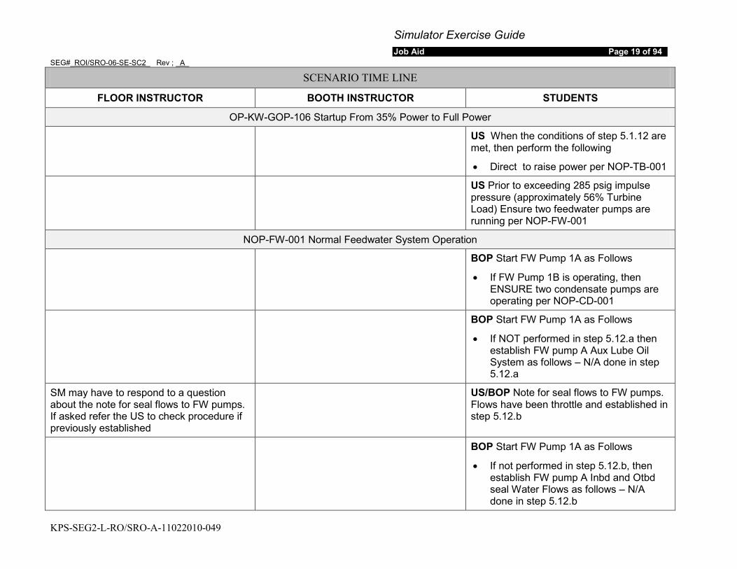
Simulator Exercise Guide Job Aid Page 19 of 94
SEG#_ROI/SRO-06-SE-SC2_ Rev ; _A_
KPS-SEG2-L-RO/SRO-A-11022010-049
SCENARIO TIME LINE
FLOOR INSTRUCTOR BOOTH INSTRUCTOR STUDENTS
OP-KW-GOP-106 Startup From 35% Power to Full Power
US When the conditions of step 5.1.12 are met, then perform the following
• Direct to raise power per NOP-TB-001
US Prior to exceeding 285 psig impulse pressure (approximately 56% Turbine Load) Ensure two feedwater pumps are running per NOP-FW-001
NOP-FW-001 Normal Feedwater System Operation
BOP Start FW Pump 1A as Follows
• If FW Pump 1B is operating, then ENSURE two condensate pumps are operating per NOP-CD-001
BOP Start FW Pump 1A as Follows
• If NOT performed in step 5.12.a then establish FW pump A Aux Lube Oil System as follows – N/A done in step 5.12.a
SM may have to respond to a question about the note for seal flows to FW pumps. If asked refer the US to check procedure if previously established
US/BOP Note for seal flows to FW pumps. Flows have been throttle and established in step 5.12.b
BOP Start FW Pump 1A as Follows
• If not performed in step 5.12.b, then establish FW pump A Inbd and Otbd seal Water Flows as follows – N/A done in step 5.12.b

Simulator Exercise Guide Job Aid Page 20 of 94
SEG#_ROI/SRO-06-SE-SC2_ Rev ; _A_
KPS-SEG2-L-RO/SRO-A-11022010-049
SCENARIO TIME LINE
FLOOR INSTRUCTOR BOOTH INSTRUCTOR STUDENTS
BOP Start FW Pump 1A as Follows
• Ensure C-17A OPEN
ROLE: EO
REQUEST: ENSURE FW-100A and FW-102A Locked OPEN
RESPONSE: Acknowledge request and report that FW-100A Locked Open after Delay
DELAY: 1 minute
BOP Start FW Pump 1A as Follows
• Ensure FW-100A, Feedwater Recric Line at FWP 1A Discharge Locked Open
• ENSURE FW-102A, FWP 1A Recric Line at Condenser 1A, Locked Open
BOP Start FW Pump 1A as Follows
• Check the following annunciators are OFF:
• 47061-A Feedwater Pump Trip
• 47061-G FWP A/B Suction Pressure Low
• 47063-C Feedwater Pump A Abnormal
• 47064-C Feedwater Pump A Vibration
• 47065-C FWP Seal Water Filter DP High
BOP Start FW Pump 1A as Follows
• Display FW Pumps temperatures from the Feedwater Pumps graphical display using PPCS
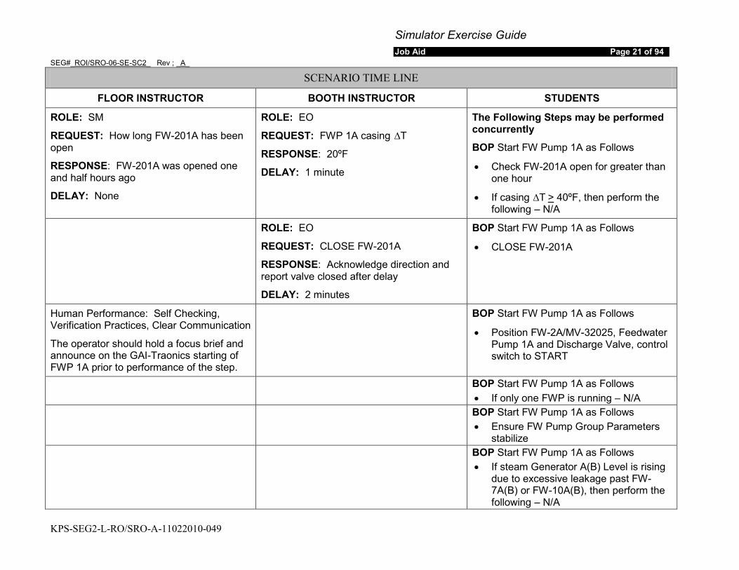
Simulator Exercise Guide Job Aid Page 21 of 94
SEG#_ROI/SRO-06-SE-SC2_ Rev ; _A_
KPS-SEG2-L-RO/SRO-A-11022010-049
SCENARIO TIME LINE
FLOOR INSTRUCTOR BOOTH INSTRUCTOR STUDENTS
ROLE: SM
REQUEST: How long FW-201A has been open
RESPONSE: FW-201A was opened one and half hours ago
DELAY: None
ROLE: EO
REQUEST: FWP 1A casing ∆T
RESPONSE: 20ºF
DELAY: 1 minute
The Following Steps may be performed concurrently
BOP Start FW Pump 1A as Follows
• Check FW-201A open for greater than one hour
• If casing ∆T > 40ºF, then perform the following – N/A
ROLE: EO
REQUEST: CLOSE FW-201A
RESPONSE: Acknowledge direction and report valve closed after delay
DELAY: 2 minutes
BOP Start FW Pump 1A as Follows
• CLOSE FW-201A
Human Performance: Self Checking, Verification Practices, Clear Communication
The operator should hold a focus brief and announce on the GAI-Traonics starting of FWP 1A prior to performance of the step.
BOP Start FW Pump 1A as Follows
• Position FW-2A/MV-32025, Feedwater Pump 1A and Discharge Valve, control switch to START
BOP Start FW Pump 1A as Follows • If only one FWP is running – N/A
BOP Start FW Pump 1A as Follows • Ensure FW Pump Group Parameters
stabilize BOP Start FW Pump 1A as Follows
• If steam Generator A(B) Level is rising due to excessive leakage past FW-7A(B) or FW-10A(B), then perform the following – N/A
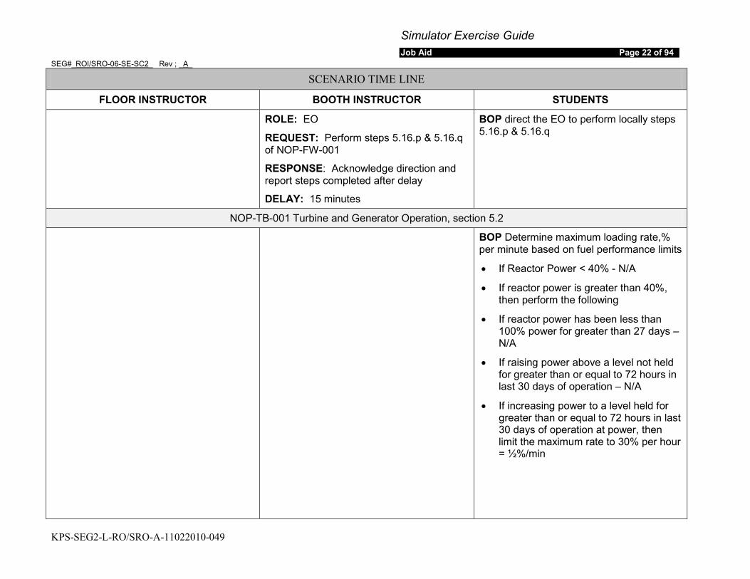
Simulator Exercise Guide Job Aid Page 22 of 94
SEG#_ROI/SRO-06-SE-SC2_ Rev ; _A_
KPS-SEG2-L-RO/SRO-A-11022010-049
SCENARIO TIME LINE
FLOOR INSTRUCTOR BOOTH INSTRUCTOR STUDENTS
ROLE: EO
REQUEST: Perform steps 5.16.p & 5.16.q of NOP-FW-001
RESPONSE: Acknowledge direction and report steps completed after delay
DELAY: 15 minutes
BOP direct the EO to perform locally steps 5.16.p & 5.16.q
NOP-TB-001 Turbine and Generator Operation, section 5.2
BOP Determine maximum loading rate,% per minute based on fuel performance limits
• If Reactor Power < 40% - N/A
• If reactor power is greater than 40%, then perform the following
• If reactor power has been less than 100% power for greater than 27 days – N/A
• If raising power above a level not held for greater than or equal to 72 hours in last 30 days of operation – N/A
• If increasing power to a level held for greater than or equal to 72 hours in last 30 days of operation at power, then limit the maximum rate to 30% per hour = ½%/min
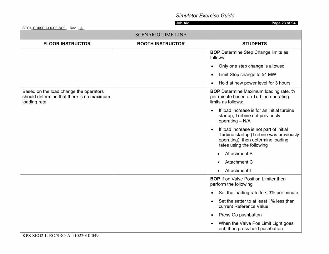
Simulator Exercise Guide Job Aid Page 23 of 94
SEG#_ROI/SRO-06-SE-SC2_ Rev ; _A_
KPS-SEG2-L-RO/SRO-A-11022010-049
SCENARIO TIME LINE
FLOOR INSTRUCTOR BOOTH INSTRUCTOR STUDENTS
BOP Determine Step Change limits as follows
• Only one step change is allowed
• Limit Step change to 54 MW
• Hold at new power level for 3 hours
Based on the load change the operators should determine that there is no maximum loading rate
BOP Determine Maximum loading rate, % per minute based on Turbine operating limits as follows:
• If load increase is for an initial turbine startup, Turbine not previously operating – N/A
• If load increase is not part of initial Turbine startup (Turbine was previously operating), then determine loading rates using the following
• Attachment B
• Attachment C
• Attachment I
BOP If on Valve Position Limiter then perform the following
• Set the loading rate to < 3% per minute
• Set the setter to at least 1% less than current Reference Value
• Press Go pushbutton
• When the Valve Pos Limit Light goes out, then press hold pushbutton

Simulator Exercise Guide Job Aid Page 24 of 94
SEG#_ROI/SRO-06-SE-SC2_ Rev ; _A_
KPS-SEG2-L-RO/SRO-A-11022010-049
SCENARIO TIME LINE
FLOOR INSTRUCTOR BOOTH INSTRUCTOR STUDENTS
BOP raise load as follows
• Set Setter to required load using reference Control UP/DOWN pushbuttons
• Set loading rate % per minute as determined by US
• Ensure loading rate % per minute less than the following
• Maximum allowed by fuel performance and Turbine Operating Limits
ROLE: SM
REQUEST: Inform Demi of Load increase
RESPONSE: Acknowledge direction to inform Demi of load increase wait delay then inform US DEMI has been informed of load increase
DELAY: 2 minutes
ROLE: DEMI
REQUEST: Inform of Load increase
RESPONSE: Acknowledge load increase
DELAY: None
US inform DEMI of load increase
• Rate of load increase
• Amount of load increase
BOP Adjust Valve Pos Limit to between 2% and 3% above next stopping point to ensure load limits are not exceeded

Simulator Exercise Guide Job Aid Page 25 of 94
SEG#_ROI/SRO-06-SE-SC2_ Rev ; _A_
KPS-SEG2-L-RO/SRO-A-11022010-049
SCENARIO TIME LINE
FLOOR INSTRUCTOR BOOTH INSTRUCTOR STUDENTS
Human Performance: Clear Communications. Self Checking, Verification Practices
Operator Fundamentals: Teamwork
The operator should have a focus brief to ensure the crew is aware that the load increase is being commenced
BOP Press GO pushbutton
Operator Fundamental: Closely monitoring parameters and indications
BOP Check Control valve Position as load is raised per Attachment G
NOP-CVC-001 Boron Concentration Control, Dilution Section 5.4
There are three noted referring to reactivity control prior to performance of a dilution:
• Positive reactivity additions shall be performed using one method at a time unless performed using an approved reactivity plan
• PPCS reactivity function is the most accurate method to determine differential boron worth
• For large dilution refer to precaution and limitation Section 4.18 - The dilution per the reactivity plan is less than 1000 gallons
RO check at least one of the following pumps operating
• RXCP A
• RXCP B
• RHR Pump A
• RHR Pump B
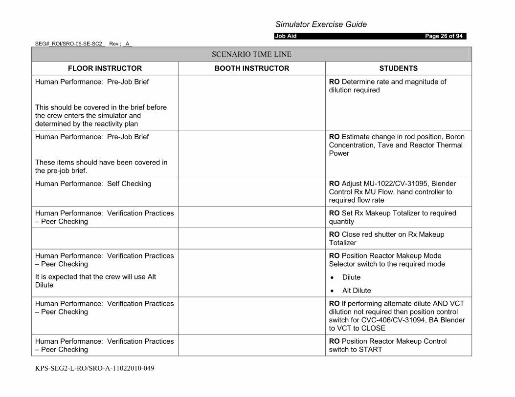
Simulator Exercise Guide Job Aid Page 26 of 94
SEG#_ROI/SRO-06-SE-SC2_ Rev ; _A_
KPS-SEG2-L-RO/SRO-A-11022010-049
SCENARIO TIME LINE
FLOOR INSTRUCTOR BOOTH INSTRUCTOR STUDENTS
Human Performance: Pre-Job Brief
This should be covered in the brief before the crew enters the simulator and determined by the reactivity plan
RO Determine rate and magnitude of dilution required
Human Performance: Pre-Job Brief
These items should have been covered in the pre-job brief.
RO Estimate change in rod position, Boron Concentration, Tave and Reactor Thermal Power
Human Performance: Self Checking RO Adjust MU-1022/CV-31095, Blender Control Rx MU Flow, hand controller to required flow rate
Human Performance: Verification Practices – Peer Checking
RO Set Rx Makeup Totalizer to required quantity
RO Close red shutter on Rx Makeup Totalizer
Human Performance: Verification Practices – Peer Checking
It is expected that the crew will use Alt Dilute
RO Position Reactor Makeup Mode Selector switch to the required mode
• Dilute
• Alt Dilute
Human Performance: Verification Practices – Peer Checking
RO If performing alternate dilute AND VCT dilution not required then position control switch for CVC-406/CV-31094, BA Blender to VCT to CLOSE
Human Performance: Verification Practices – Peer Checking
RO Position Reactor Makeup Control switch to START
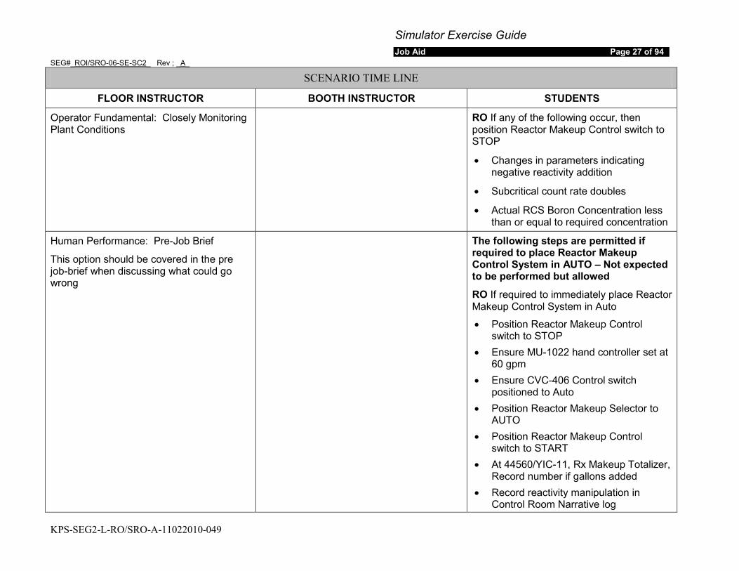
Simulator Exercise Guide Job Aid Page 27 of 94
SEG#_ROI/SRO-06-SE-SC2_ Rev ; _A_
KPS-SEG2-L-RO/SRO-A-11022010-049
SCENARIO TIME LINE
FLOOR INSTRUCTOR BOOTH INSTRUCTOR STUDENTS
Operator Fundamental: Closely Monitoring Plant Conditions
RO If any of the following occur, then position Reactor Makeup Control switch to STOP
• Changes in parameters indicating negative reactivity addition
• Subcritical count rate doubles
• Actual RCS Boron Concentration less than or equal to required concentration
Human Performance: Pre-Job Brief
This option should be covered in the pre job-brief when discussing what could go wrong
The following steps are permitted if required to place Reactor Makeup Control System in AUTO – Not expected to be performed but allowed
RO If required to immediately place Reactor Makeup Control System in Auto
• Position Reactor Makeup Control switch to STOP
• Ensure MU-1022 hand controller set at 60 gpm
• Ensure CVC-406 Control switch positioned to Auto
• Position Reactor Makeup Selector to AUTO
• Position Reactor Makeup Control switch to START
• At 44560/YIC-11, Rx Makeup Totalizer, Record number if gallons added
• Record reactivity manipulation in Control Room Narrative log
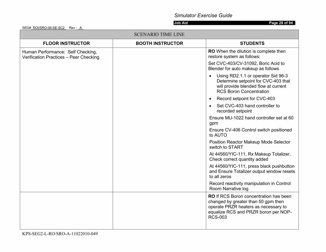
Simulator Exercise Guide Job Aid Page 28 of 94
SEG#_ROI/SRO-06-SE-SC2_ Rev ; _A_
KPS-SEG2-L-RO/SRO-A-11022010-049
SCENARIO TIME LINE
FLOOR INSTRUCTOR BOOTH INSTRUCTOR STUDENTS
Human Performance: Self Checking, Verification Practices – Peer Checking
RO When the dilution is complete then restore system as follows: Set CVC-403/CV-31092, Boric Acid to Blender for auto makeup as follows • Using RD2.1.1 or operator Sid 96-3
Determine setpoint for CVC-403 that will provide blended flow at current RCS Boron Concentration
• Record setpoint for CVC-403 • Set CVC-403 hand controller to
recorded setpoint Ensure MU-1022 hand controller set at 60 gpm Ensure CV-406 Control switch positioned to AUTO Position Reactor Makeup Mode Selector switch to START At 44560/YIC-111, Rx Makeup Totalizer, Check correct quantity added At 44560/YIC-111, press black pushbutton and Ensure Totalizer output window resets to all zeros Record reactivity manipulation in Control Room Narrative log
RO If RCS Boron concentration has been changed by greater than 50 gpm then operate PRZR heaters as necessary to equalize RCS and PRZR boron per NOP-RCS-003
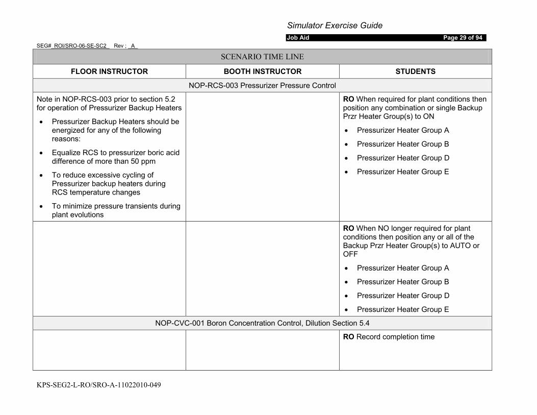
Simulator Exercise Guide Job Aid Page 29 of 94
SEG#_ROI/SRO-06-SE-SC2_ Rev ; _A_
KPS-SEG2-L-RO/SRO-A-11022010-049
SCENARIO TIME LINE
FLOOR INSTRUCTOR BOOTH INSTRUCTOR STUDENTS
NOP-RCS-003 Pressurizer Pressure Control
Note in NOP-RCS-003 prior to section 5.2 for operation of Pressurizer Backup Heaters
• Pressurizer Backup Heaters should be energized for any of the following reasons:
• Equalize RCS to pressurizer boric acid difference of more than 50 ppm
• To reduce excessive cycling of Pressurizer backup heaters during RCS temperature changes
• To minimize pressure transients during plant evolutions
RO When required for plant conditions then position any combination or single Backup Przr Heater Group(s) to ON
• Pressurizer Heater Group A
• Pressurizer Heater Group B
• Pressurizer Heater Group D
• Pressurizer Heater Group E
RO When NO longer required for plant conditions then position any or all of the Backup Przr Heater Group(s) to AUTO or OFF
• Pressurizer Heater Group A
• Pressurizer Heater Group B
• Pressurizer Heater Group D
• Pressurizer Heater Group E
NOP-CVC-001 Boron Concentration Control, Dilution Section 5.4
RO Record completion time

Simulator Exercise Guide Job Aid Page 30 of 94
SEG#_ROI/SRO-06-SE-SC2_ Rev ; _A_
KPS-SEG2-L-RO/SRO-A-11022010-049
SCENARIO TIME LINE
FLOOR INSTRUCTOR BOOTH INSTRUCTOR STUDENTS
NOP-CVC-001 Boron Concentration Control, Verification of Automatic Makeup section 5.2
During the scenario when Automatic occurs the US should direct the RO to perform this section of NOP-CVC-001 for verification of Automatic Makeup
RO Observe VCT Level on LI-112 or LI141B to ensure proper automatic control operation
RO Using the following check for proper boron concentration during automatic makeup
• CVCS BA & MU flow Recorder
• Rx Makeup and Boric Acid Flow Totalizers
• Boric Acid Tank level change to Boric Acid Totalizer Change
• Source Range Count Rate
• Change in Tave
• Control rod motion
RO If adjustment to BA concentration of makeup flow is required during auto makeup then adjust CVC-403 as required to raise or lower concentration
There is note for during CVCs blended flow makeups with low BA flow one BA transfer pump may provide most of the flow and cause a low flow condition in the other pump – Not Expected
RO If low flow to single BA transfer pump is suspected during parallel pump operation then perform the following:
Throttle Open the following as necessary to in increase system flow
• CVC-712A/CV-311106, Bat A Recric Control

Simulator Exercise Guide Job Aid Page 31 of 94
SEG#_ROI/SRO-06-SE-SC2_ Rev ; _A_
KPS-SEG2-L-RO/SRO-A-11022010-049
SCENARIO TIME LINE
FLOOR INSTRUCTOR BOOTH INSTRUCTOR STUDENTS
• CVC-712B/CV-311107, Bat B Recric Control
Monitor BAST A Levels using the following instruments
• LI-106
• LI-172
• LI-190
• LI-196
Monitor BAST B Levels using the following instruments:
• LI-102
• LI-171
• LI-189
• LI-197
Adjust the following as required to maintain BAST Levels approximately equal
• CVC-712A
• CVC-712B
When Makeup is complete then close the following
• CVC-712A
• CVC-712B

Simulator Exercise Guide Job Aid Page 32 of 94
SEG#_ROI/SRO-06-SE-SC2_ Rev ; _A_
KPS-SEG2-L-RO/SRO-A-11022010-049
SCENARIO TIME LINE
FLOOR INSTRUCTOR BOOTH INSTRUCTOR STUDENTS
RO When automatic makeup is stopped then perform the following
• Record Boric Acid Totalizer Ouput
• Record Rx Makeup Totalizer output
• At 44559/YIC-110 Boric Acid Totalizer press the black reset pushbutton and ensure totalizer output window resets to all zeros
• At 44560/YIC-111 Rx Makeup Totalizer press the black reset pushbutton and ensure totalizer output window resets to all zeros
• Record reactivity manipulation in Control Room Narrative log
• Record Completion Time
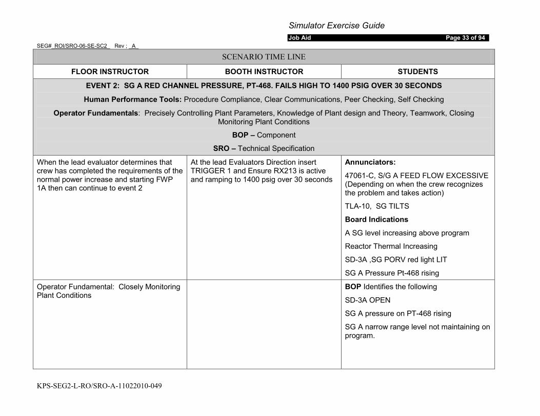
Simulator Exercise Guide Job Aid Page 33 of 94
SEG#_ROI/SRO-06-SE-SC2_ Rev ; _A_
KPS-SEG2-L-RO/SRO-A-11022010-049
SCENARIO TIME LINE
FLOOR INSTRUCTOR BOOTH INSTRUCTOR STUDENTS
EVENT 2: SG A RED CHANNEL PRESSURE, PT-468. FAILS HIGH TO 1400 PSIG OVER 30 SECONDS
Human Performance Tools: Procedure Compliance, Clear Communications, Peer Checking, Self Checking
Operator Fundamentals: Precisely Controlling Plant Parameters, Knowledge of Plant design and Theory, Teamwork, Closing Monitoring Plant Conditions
BOP – Component
SRO – Technical Specification
When the lead evaluator determines that crew has completed the requirements of the normal power increase and starting FWP 1A then can continue to event 2
At the lead Evaluators Direction insert TRIGGER 1 and Ensure RX213 is active and ramping to 1400 psig over 30 seconds
Annunciators:
47061-C, S/G A FEED FLOW EXCESSIVE (Depending on when the crew recognizes the problem and takes action)
TLA-10, SG TILTS
Board Indications
A SG level increasing above program
Reactor Thermal Increasing
SD-3A ,SG PORV red light LIT
SG A Pressure Pt-468 rising
Operator Fundamental: Closely Monitoring Plant Conditions
BOP Identifies the following
SD-3A OPEN
SG A pressure on PT-468 rising
SG A narrow range level not maintaining on program.
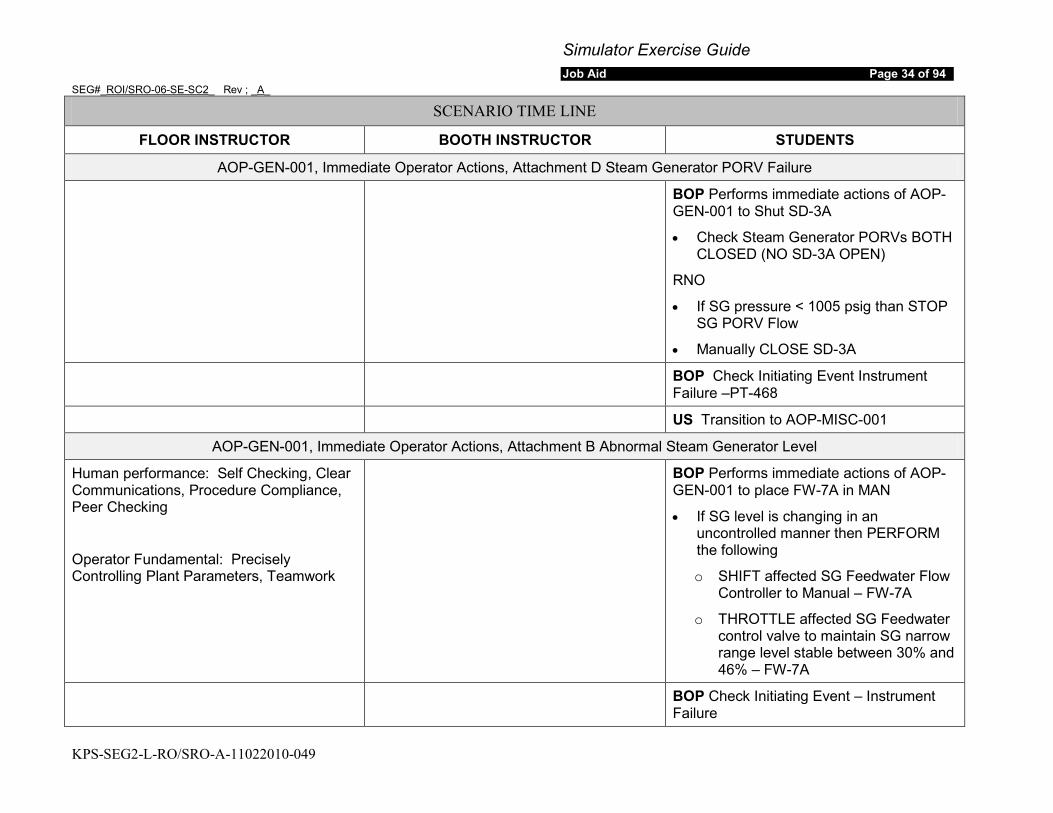
Simulator Exercise Guide Job Aid Page 34 of 94
SEG#_ROI/SRO-06-SE-SC2_ Rev ; _A_
KPS-SEG2-L-RO/SRO-A-11022010-049
SCENARIO TIME LINE
FLOOR INSTRUCTOR BOOTH INSTRUCTOR STUDENTS
AOP-GEN-001, Immediate Operator Actions, Attachment D Steam Generator PORV Failure
BOP Performs immediate actions of AOP-GEN-001 to Shut SD-3A
• Check Steam Generator PORVs BOTH CLOSED (NO SD-3A OPEN)
RNO
• If SG pressure < 1005 psig than STOP SG PORV Flow
• Manually CLOSE SD-3A
BOP Check Initiating Event Instrument Failure –PT-468
US Transition to AOP-MISC-001
AOP-GEN-001, Immediate Operator Actions, Attachment B Abnormal Steam Generator Level
Human performance: Self Checking, Clear Communications, Procedure Compliance, Peer Checking
Operator Fundamental: Precisely Controlling Plant Parameters, Teamwork
BOP Performs immediate actions of AOP-GEN-001 to place FW-7A in MAN
• If SG level is changing in an uncontrolled manner then PERFORM the following
o SHIFT affected SG Feedwater Flow Controller to Manual – FW-7A
o THROTTLE affected SG Feedwater control valve to maintain SG narrow range level stable between 30% and 46% – FW-7A
BOP Check Initiating Event – Instrument Failure
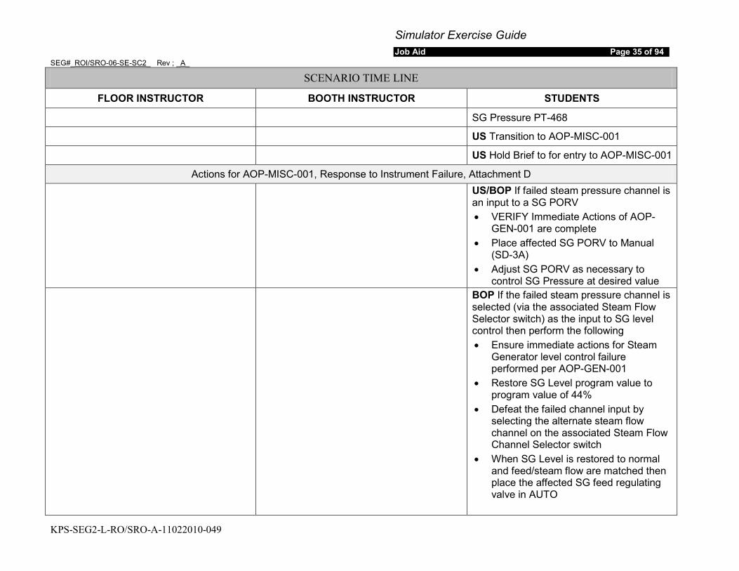
Simulator Exercise Guide Job Aid Page 35 of 94
SEG#_ROI/SRO-06-SE-SC2_ Rev ; _A_
KPS-SEG2-L-RO/SRO-A-11022010-049
SCENARIO TIME LINE
FLOOR INSTRUCTOR BOOTH INSTRUCTOR STUDENTS
SG Pressure PT-468
US Transition to AOP-MISC-001
US Hold Brief to for entry to AOP-MISC-001
Actions for AOP-MISC-001, Response to Instrument Failure, Attachment D
US/BOP If failed steam pressure channel is an input to a SG PORV • VERIFY Immediate Actions of AOP-
GEN-001 are complete • Place affected SG PORV to Manual
(SD-3A) • Adjust SG PORV as necessary to
control SG Pressure at desired value BOP If the failed steam pressure channel is
selected (via the associated Steam Flow Selector switch) as the input to SG level control then perform the following • Ensure immediate actions for Steam
Generator level control failure performed per AOP-GEN-001
• Restore SG Level program value to program value of 44%
• Defeat the failed channel input by selecting the alternate steam flow channel on the associated Steam Flow Channel Selector switch
• When SG Level is restored to normal and feed/steam flow are matched then place the affected SG feed regulating valve in AUTO
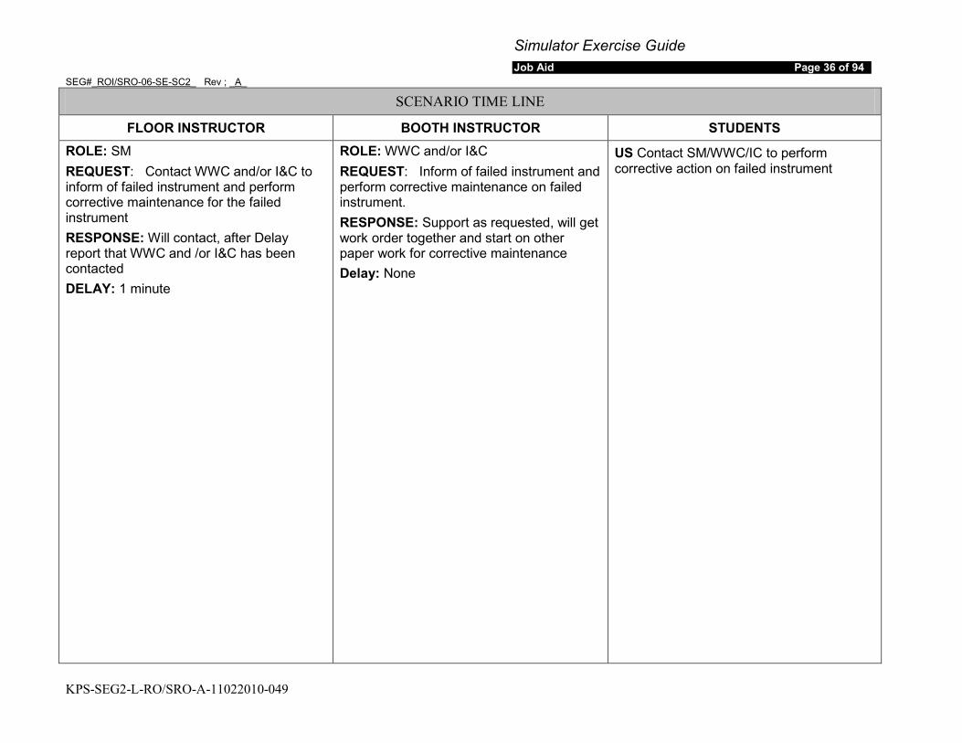
Simulator Exercise Guide Job Aid Page 36 of 94
SEG#_ROI/SRO-06-SE-SC2_ Rev ; _A_
KPS-SEG2-L-RO/SRO-A-11022010-049
SCENARIO TIME LINE
FLOOR INSTRUCTOR BOOTH INSTRUCTOR STUDENTS ROLE: SM REQUEST: Contact WWC and/or I&C to inform of failed instrument and perform corrective maintenance for the failed instrument RESPONSE: Will contact, after Delay report that WWC and /or I&C has been contacted DELAY: 1 minute
ROLE: WWC and/or I&C REQUEST: Inform of failed instrument and perform corrective maintenance on failed instrument. RESPONSE: Support as requested, will get work order together and start on other paper work for corrective maintenance Delay: None
US Contact SM/WWC/IC to perform corrective action on failed instrument
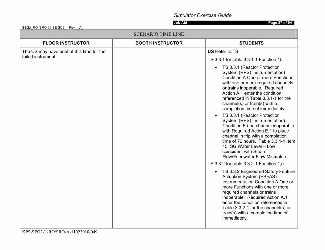
Simulator Exercise Guide Job Aid Page 37 of 94
SEG#_ROI/SRO-06-SE-SC2_ Rev ; _A_
KPS-SEG2-L-RO/SRO-A-11022010-049
SCENARIO TIME LINE
FLOOR INSTRUCTOR BOOTH INSTRUCTOR STUDENTS
The US may have brief at this time for the failed instrument.
US Refer to TS
TS 3.3.1 for table 3.3.1-1 Function 15
• TS 3.3.1 (Reactor Protection System (RPS) Instrumentation) Condition A One or more Functions with one or more required channels or trains inoperable. Required Action A.1 enter the condition referenced in Table 3.3.1-1 for the channel(s) or train(s) with a completion time of immediately.
• TS 3.3.1 (Reactor Protection System (RPS) Instrumentation) Condition E one channel inoperable with Required Action E.1 to place channel in trip with a completion time of 72 hours. Table 3.3.1-1 Item 15. SG Water Level – Low coincident with Steam Flow/Feedwater Flow Mismatch.
TS 3.3.2 for table 3.3.2-1 Function 1,e
• TS 3.3.2 Engineered Safety Feature Actuation System (ESFAS) Instrumentation Condition A One or more Functions with one or more required channels or trains inoperable. Required Action A.1 enter the condition referenced in Table 3.3.2-1 for the channel(s) or train(s) with a completion time of immediately.
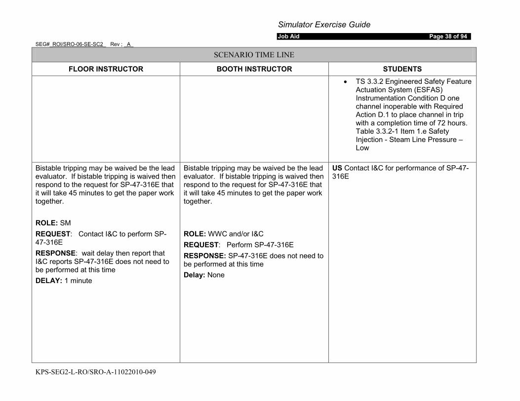
Simulator Exercise Guide Job Aid Page 38 of 94
SEG#_ROI/SRO-06-SE-SC2_ Rev ; _A_
KPS-SEG2-L-RO/SRO-A-11022010-049
SCENARIO TIME LINE
FLOOR INSTRUCTOR BOOTH INSTRUCTOR STUDENTS • TS 3.3.2 Engineered Safety Feature
Actuation System (ESFAS) Instrumentation Condition D one channel inoperable with Required Action D.1 to place channel in trip with a completion time of 72 hours. Table 3.3.2-1 Item 1.e Safety Injection - Steam Line Pressure – Low
Bistable tripping may be waived be the lead evaluator. If bistable tripping is waived then respond to the request for SP-47-316E that it will take 45 minutes to get the paper work together. ROLE: SM REQUEST: Contact I&C to perform SP-47-316E RESPONSE: wait delay then report that I&C reports SP-47-316E does not need to be performed at this time DELAY: 1 minute
Bistable tripping may be waived be the lead evaluator. If bistable tripping is waived then respond to the request for SP-47-316E that it will take 45 minutes to get the paper work together. ROLE: WWC and/or I&C REQUEST: Perform SP-47-316E RESPONSE: SP-47-316E does not need to be performed at this time Delay: None
US Contact I&C for performance of SP-47-316E

Simulator Exercise Guide Job Aid Page 39 of 94
SEG#_ROI/SRO-06-SE-SC2_ Rev ; _A_
KPS-SEG2-L-RO/SRO-A-11022010-049
SCENARIO TIME LINE
FLOOR INSTRUCTOR BOOTH INSTRUCTOR STUDENTS If bistable tripping has been omitted by the lead evaluator then this statement is N/A ROLE: SM REQUEST: Send and I&C tech to the control room for the tripping of bistables RESPONSE: Acknowledge the request and inform the Control Room that an I&C tech will be in the control room in about 2 minutes Delay: 1 minute
If bistable tripping has been omitted by the lead evaluator then this statement is N/A ROLE: WWC and/or I&C REQUEST: Send and I&C tech to the control room for the tripping of bistables RESPONSE: Acknowledge the request and inform the Control Room that an I&C tech will be in the control room in about 2 minutes Delay: None
Booth operator go to the control room as the I&C tech 2 minutes after the call to trip bistables
If bistable tripping has been omitted by the lead evaluator then this statement is N/A CREW Check the existing bistable status to ensure a reactor trip will not occur when the failed instrument is placed in tripped condition
If bistable tripping has been omitted by the lead evaluator then this statement is N/A Participate in brief for tripping of bistables after brief is complete then coordinate with the operator and trip bistables
Trigger 3 Bistable 466B
Trigger 5 Bistable 466C
Trigger 7 Bistable 468B
Trigger 9 Bistable 468A
If bistable tripping has been omitted by the lead evaluator then this statement is N/A CREW coordinate tripping of bistables
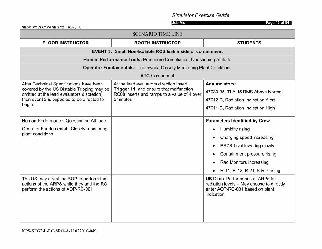
Simulator Exercise Guide Job Aid Page 40 of 94
SEG#_ROI/SRO-06-SE-SC2_ Rev ; _A_
KPS-SEG2-L-RO/SRO-A-11022010-049
SCENARIO TIME LINE
FLOOR INSTRUCTOR BOOTH INSTRUCTOR STUDENTS
EVENT 3: Small Non-Isolable RCS leak inside of containment
Human Performance Tools: Procedure Compliance, Questioning Attitude
Operator Fundamentals: Teamwork, Closely Monitoring Plant Conditions
ATC-Component
After Technical Specifications have been covered by the US Bistable Tripping may be omitted at the lead evaluators discretion) then event 2 is expected to be directed to begin.
At the lead evaluators direction insert Trigger 11 and ensure that malfunction RC08 inserts and ramps to a value of 4 over 5minutes
Annunciators:
47033-35, TLA-15 RMS Above Normal
47012-B, Radiation Indication Alert
47011-B, Radiation Indication High
Human Performance: Questioning Attitude
Operator Fundamental: Closely monitoring plant conditions
Parameters Identified by Crew
• Humidity rising
• Charging speed increasing
• PRZR level lowering slowly
• Containment pressure rising
• Rad Monitors increasing
• R-11, R-12, R-21, & R-7 rising
The US may direct the BOP to perform the actions of the ARPS while they and the RO perform the actions of AOP-RC-001
US Direct Performance of ARPs for radiation levels – May choose to directly enter AOP-RC-001 based on plant indication

Simulator Exercise Guide Job Aid Page 41 of 94
SEG#_ROI/SRO-06-SE-SC2_ Rev ; _A_
KPS-SEG2-L-RO/SRO-A-11022010-049
SCENARIO TIME LINE
FLOOR INSTRUCTOR BOOTH INSTRUCTOR STUDENTS
47033-35 TLA 15 RMS Above Normal
ROLE: SM REQUEST: Inform RP of Rad Monitor Alarms and to survey the affected areas. RESPONSE: Acknowledge request to contact RP and after delay report that RP has been informed
DELAY: One Minute
Note: R-7 may alarm depending on the crew reaction time
ROLE: RP REQUEST: Inform of Rad Monitor Alarms and to survey the affected areas. RESPONSE: Acknowledge the Rad Monitor Alarms & Surveys. And any other request made by the crew.
DELAY: None
BOP/RO Check alarm due to any of the following
• R-15
• R-19
• R-42
• R-43
Operator should note that alarm is due to R-11, R-12 & R-21
RNO
• If Alarm is due to annunciator failure-N/A
• Direct RP to Survey the affected area
The US may elect to have the BOP perform the actions AOP-RM-001 vice directing the procedure. The BOP will have keep the US informed of equipment manipulations or problems encountered during performance of the procedure
US Transition to AOP-RM-001
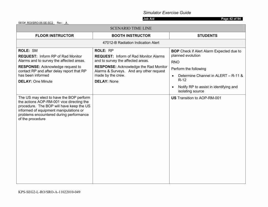
Simulator Exercise Guide Job Aid Page 42 of 94
SEG#_ROI/SRO-06-SE-SC2_ Rev ; _A_
KPS-SEG2-L-RO/SRO-A-11022010-049
SCENARIO TIME LINE
FLOOR INSTRUCTOR BOOTH INSTRUCTOR STUDENTS
47012-B Radiation Indication Alert
ROLE: SM REQUEST: Inform RP of Rad Monitor Alarms and to survey the affected areas. RESPONSE: Acknowledge request to contact RP and after delay report that RP has been informed DELAY: One Minute
ROLE: RP REQUEST: Inform of Rad Monitor Alarms and to survey the affected areas. RESPONSE: Acknowledge the Rad Monitor Alarms & Surveys. And any other request made by the crew. DELAY: None
BOP Check if Alert Alarm Expected due to planned evolution
RNO
Perform the following
• Determine Channel in ALERT – R-11 & R-12
• Notify RP to assist in identifying and isolating source
The US may elect to have the BOP perform the actions AOP-RM-001 vice directing the procedure. The BOP will have keep the US informed of equipment manipulations or problems encountered during performance of the procedure
US Transition to AOP-RM-001

Simulator Exercise Guide Job Aid Page 43 of 94
SEG#_ROI/SRO-06-SE-SC2_ Rev ; _A_
KPS-SEG2-L-RO/SRO-A-11022010-049
SCENARIO TIME LINE
FLOOR INSTRUCTOR BOOTH INSTRUCTOR STUDENTS
47011-B Radiation Indication High
ROLE: SM REQUEST: Inform RP of Rad Monitor Alarms and to survey the affected areas. RESPONSE: Acknowledge request to contact RP and after delay report that RP has been informed DELAY: One Minute
ROLE: RP REQUEST: Inform of Rad Monitor Alarms and to survey the affected areas. RESPONSE: Acknowledge the Rad Monitor Alarms & Surveys. And any other request made by the crew. DELAY: None
BOP Check if High Alarm Expected due to planned evolution
RNO
Perform the following
• Determine Channel in ALERT – R-11, R-12 & R-21
• Notify RP to assist in identifying and isolating source
The US may elect to have the BOP perform the actions AOP-RM-001 vice directing the procedure. The BOP will have keep the US informed of equipment manipulations or problems encountered during performance of the procedure
US Transition to AOP-RM-001

Simulator Exercise Guide Job Aid Page 44 of 94
SEG#_ROI/SRO-06-SE-SC2_ Rev ; _A_
KPS-SEG2-L-RO/SRO-A-11022010-049
SCENARIO TIME LINE
FLOOR INSTRUCTOR BOOTH INSTRUCTOR STUDENTS
AOP-RM-001 Abnormal Radiation Monitoring System
Depending on the speed of the crew to get to this point R-7 may be in alarm or alarm during the performance of the procedure. If in alarm the operator will determine that no personnel are in containment and only action is to announce the event
(CAS) BOP Check if Personnel should be evacuated
R-2 through R-10 in Alarm - NO
BOP Radiation Monitors – None Failed downscale
Depending on the speed of the crew to get to this point R-7 may be in alarm or alarm during the performance of the procedure
BOP Check operation of Each Affected Radiation Monitor Using Table 1
Verify all applicable steps from table 1 below completed – Determine R-11, R-12 & R-21 are the affected Radiation Monitors.
Table 1
Affected Radiation Monitor
GO TO STEP Page
R-7 9 8
R-11 12 10
R-12 13 11
R-21 22 20
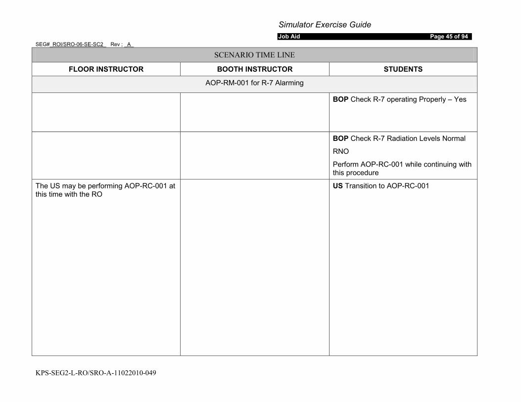
Simulator Exercise Guide Job Aid Page 45 of 94
SEG#_ROI/SRO-06-SE-SC2_ Rev ; _A_
KPS-SEG2-L-RO/SRO-A-11022010-049
SCENARIO TIME LINE
FLOOR INSTRUCTOR BOOTH INSTRUCTOR STUDENTS
AOP-RM-001 for R-7 Alarming
BOP Check R-7 operating Properly – Yes
BOP Check R-7 Radiation Levels Normal
RNO
Perform AOP-RC-001 while continuing with this procedure
The US may be performing AOP-RC-001 at this time with the RO
US Transition to AOP-RC-001
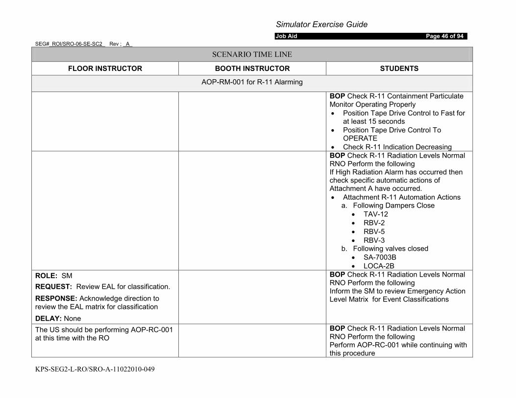
Simulator Exercise Guide Job Aid Page 46 of 94
SEG#_ROI/SRO-06-SE-SC2_ Rev ; _A_
KPS-SEG2-L-RO/SRO-A-11022010-049
SCENARIO TIME LINE
FLOOR INSTRUCTOR BOOTH INSTRUCTOR STUDENTS
AOP-RM-001 for R-11 Alarming
BOP Check R-11 Containment Particulate Monitor Operating Properly • Position Tape Drive Control to Fast for
at least 15 seconds • Position Tape Drive Control To
OPERATE • Check R-11 Indication Decreasing
BOP Check R-11 Radiation Levels Normal RNO Perform the following If High Radiation Alarm has occurred then check specific automatic actions of Attachment A have occurred. • Attachment R-11 Automation Actions
a. Following Dampers Close • TAV-12 • RBV-2 • RBV-5 • RBV-3
b. Following valves closed • SA-7003B • LOCA-2B
ROLE: SM REQUEST: Review EAL for classification. RESPONSE: Acknowledge direction to review the EAL matrix for classification DELAY: None
BOP Check R-11 Radiation Levels Normal RNO Perform the following Inform the SM to review Emergency Action Level Matrix for Event Classifications
The US should be performing AOP-RC-001 at this time with the RO
BOP Check R-11 Radiation Levels Normal RNO Perform the following Perform AOP-RC-001 while continuing with this procedure
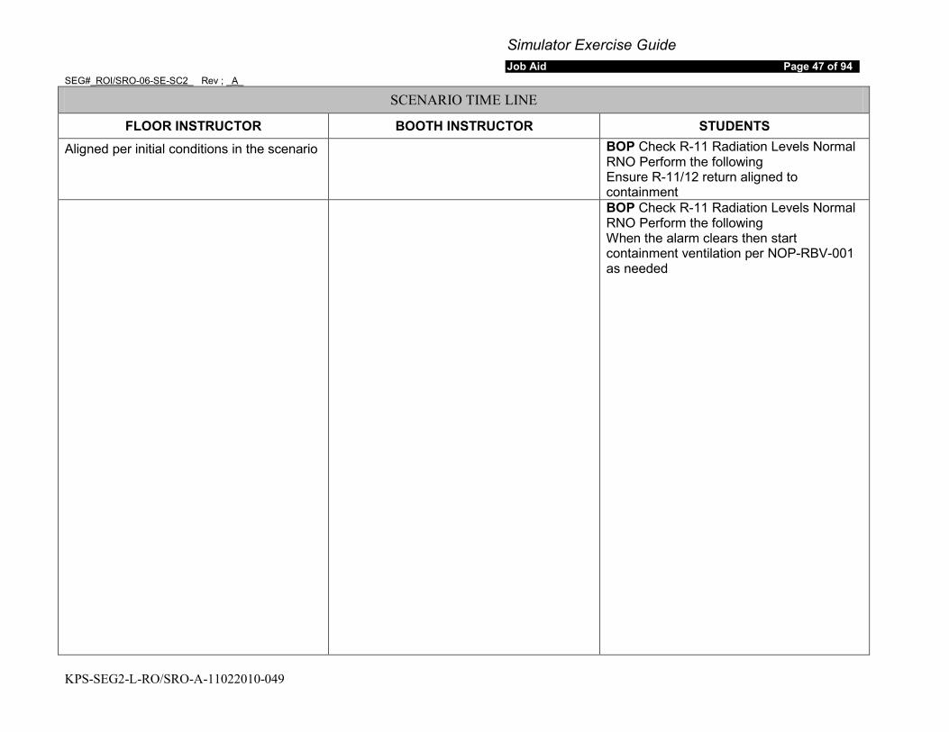
Simulator Exercise Guide Job Aid Page 47 of 94
SEG#_ROI/SRO-06-SE-SC2_ Rev ; _A_
KPS-SEG2-L-RO/SRO-A-11022010-049
SCENARIO TIME LINE
FLOOR INSTRUCTOR BOOTH INSTRUCTOR STUDENTS Aligned per initial conditions in the scenario BOP Check R-11 Radiation Levels Normal
RNO Perform the following Ensure R-11/12 return aligned to containment
BOP Check R-11 Radiation Levels Normal RNO Perform the following When the alarm clears then start containment ventilation per NOP-RBV-001 as needed
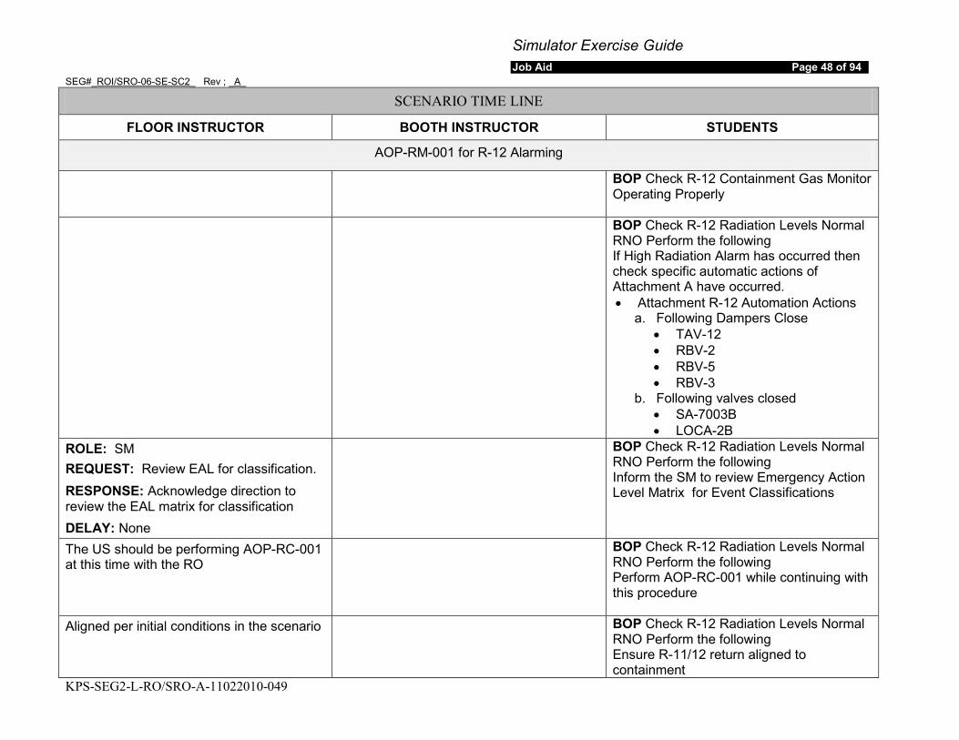
Simulator Exercise Guide Job Aid Page 48 of 94
SEG#_ROI/SRO-06-SE-SC2_ Rev ; _A_
KPS-SEG2-L-RO/SRO-A-11022010-049
SCENARIO TIME LINE
FLOOR INSTRUCTOR BOOTH INSTRUCTOR STUDENTS
AOP-RM-001 for R-12 Alarming
BOP Check R-12 Containment Gas Monitor Operating Properly
BOP Check R-12 Radiation Levels Normal RNO Perform the following If High Radiation Alarm has occurred then check specific automatic actions of Attachment A have occurred. • Attachment R-12 Automation Actions
a. Following Dampers Close • TAV-12 • RBV-2 • RBV-5 • RBV-3
b. Following valves closed • SA-7003B • LOCA-2B
ROLE: SM REQUEST: Review EAL for classification. RESPONSE: Acknowledge direction to review the EAL matrix for classification DELAY: None
BOP Check R-12 Radiation Levels Normal RNO Perform the following Inform the SM to review Emergency Action Level Matrix for Event Classifications
The US should be performing AOP-RC-001 at this time with the RO
BOP Check R-12 Radiation Levels Normal RNO Perform the following Perform AOP-RC-001 while continuing with this procedure
Aligned per initial conditions in the scenario BOP Check R-12 Radiation Levels Normal RNO Perform the following Ensure R-11/12 return aligned to containment
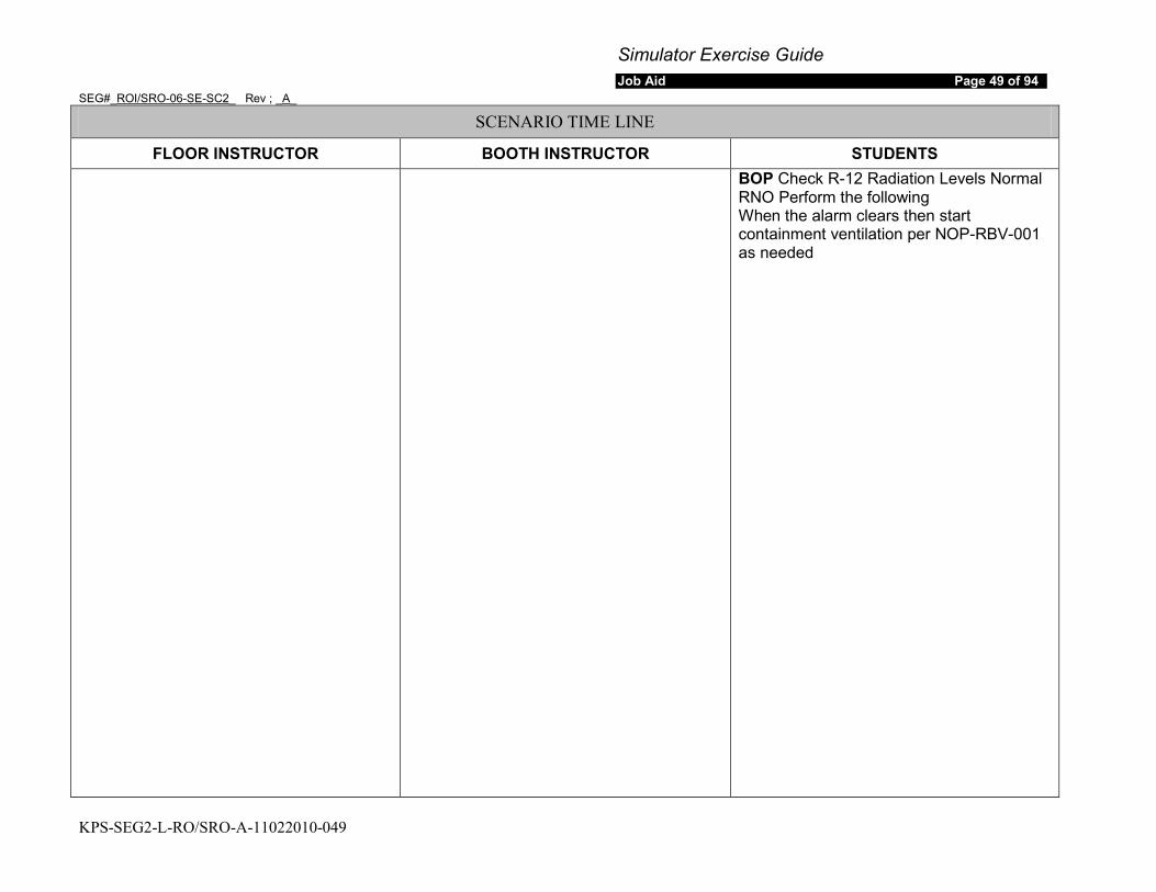
Simulator Exercise Guide Job Aid Page 49 of 94
SEG#_ROI/SRO-06-SE-SC2_ Rev ; _A_
KPS-SEG2-L-RO/SRO-A-11022010-049
SCENARIO TIME LINE
FLOOR INSTRUCTOR BOOTH INSTRUCTOR STUDENTS BOP Check R-12 Radiation Levels Normal
RNO Perform the following When the alarm clears then start containment ventilation per NOP-RBV-001 as needed

Simulator Exercise Guide Job Aid Page 50 of 94
SEG#_ROI/SRO-06-SE-SC2_ Rev ; _A_
KPS-SEG2-L-RO/SRO-A-11022010-049
SCENARIO TIME LINE
FLOOR INSTRUCTOR BOOTH INSTRUCTOR STUDENTS
AOP-RM-001 for R-21 Alarming
BOP Check R-21 Containment Vent Monitor Operating Properly
BOP Check R-21 Radiation Levels Normal RNO If High Radiation alarm has occurred then check specific automatic actions of attachment A have occurred • Attachment A Automatic Actions
a. The following Dampers Close • TAV-12 • RBV-1 • RBV-4 • RBV-5
b. The Following Valves Close • LOCA-100B • LOCA-201B
ROLE: SM REQUEST: Review EAL for classification. RESPONSE: Acknowledge direction to review the EAL matrix for classification DELAY: None
BOP Check R-21 Radiation Levels Normal RNO Inform the SM to review Emergency Action Level Matrix for Event Classifications
The US should be performing AOP-RC-001 at this time with the RO
BOP Check R-21 Radiation Levels Normal RNO Perform the following Perform AOP-RC-001 while continuing with this procedure
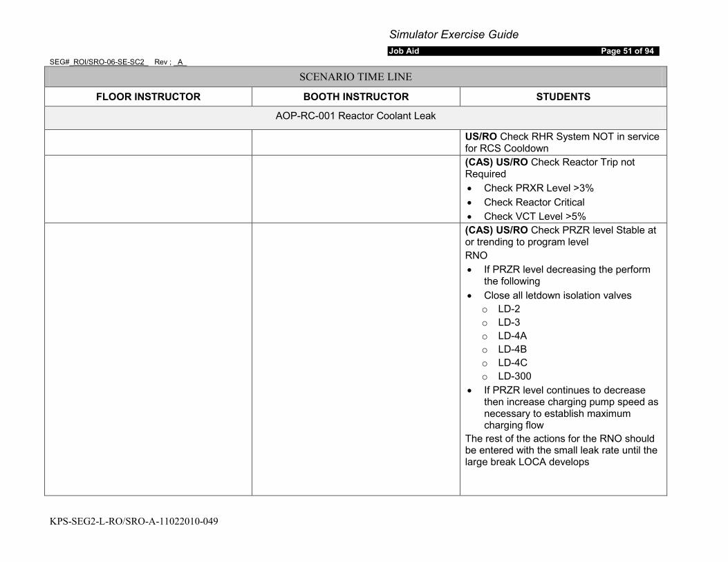
Simulator Exercise Guide Job Aid Page 51 of 94
SEG#_ROI/SRO-06-SE-SC2_ Rev ; _A_
KPS-SEG2-L-RO/SRO-A-11022010-049
SCENARIO TIME LINE
FLOOR INSTRUCTOR BOOTH INSTRUCTOR STUDENTS
AOP-RC-001 Reactor Coolant Leak
US/RO Check RHR System NOT in service for RCS Cooldown
(CAS) US/RO Check Reactor Trip not Required • Check PRXR Level >3% • Check Reactor Critical • Check VCT Level >5%
(CAS) US/RO Check PRZR level Stable at or trending to program level RNO • If PRZR level decreasing the perform
the following • Close all letdown isolation valves
o LD-2 o LD-3 o LD-4A o LD-4B o LD-4C o LD-300
• If PRZR level continues to decrease then increase charging pump speed as necessary to establish maximum charging flow
The rest of the actions for the RNO should be entered with the small leak rate until the large break LOCA develops
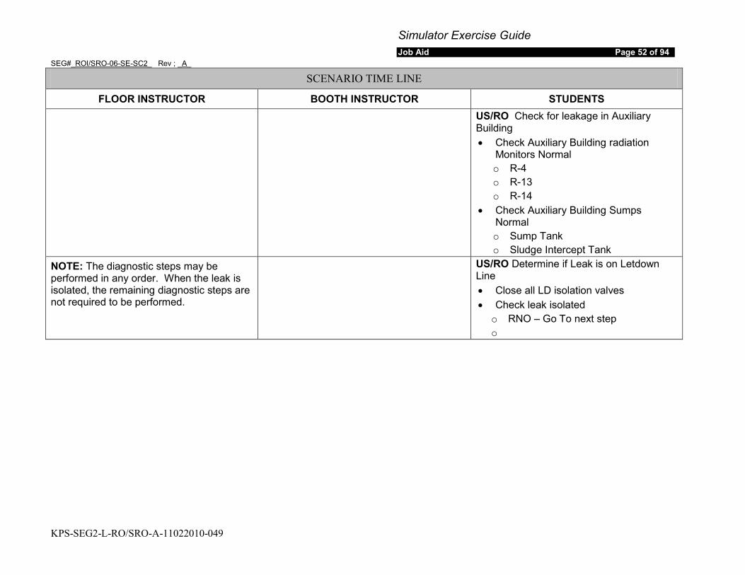
Simulator Exercise Guide Job Aid Page 52 of 94
SEG#_ROI/SRO-06-SE-SC2_ Rev ; _A_
KPS-SEG2-L-RO/SRO-A-11022010-049
SCENARIO TIME LINE
FLOOR INSTRUCTOR BOOTH INSTRUCTOR STUDENTS
US/RO Check for leakage in Auxiliary Building • Check Auxiliary Building radiation
Monitors Normal o R-4 o R-13 o R-14
• Check Auxiliary Building Sumps Normal o Sump Tank o Sludge Intercept Tank
NOTE: The diagnostic steps may be performed in any order. When the leak is isolated, the remaining diagnostic steps are not required to be performed.
US/RO Determine if Leak is on Letdown Line • Close all LD isolation valves • Check leak isolated
o RNO – Go To next step o
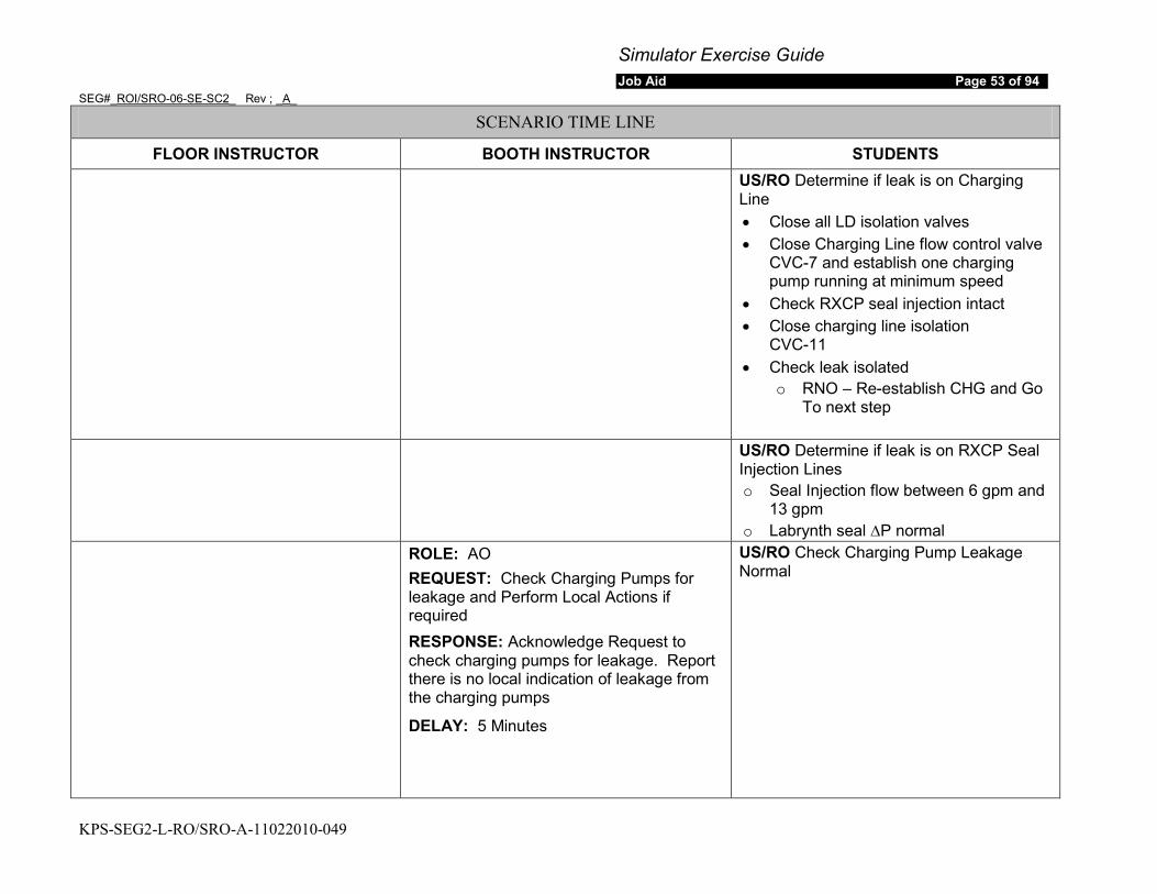
Simulator Exercise Guide Job Aid Page 53 of 94
SEG#_ROI/SRO-06-SE-SC2_ Rev ; _A_
KPS-SEG2-L-RO/SRO-A-11022010-049
SCENARIO TIME LINE
FLOOR INSTRUCTOR BOOTH INSTRUCTOR STUDENTS
US/RO Determine if leak is on Charging Line • Close all LD isolation valves • Close Charging Line flow control valve
CVC-7 and establish one charging pump running at minimum speed
• Check RXCP seal injection intact • Close charging line isolation
CVC-11 • Check leak isolated
o RNO – Re-establish CHG and Go To next step
US/RO Determine if leak is on RXCP Seal
Injection Lines o Seal Injection flow between 6 gpm and
13 gpm o Labrynth seal ∆P normal
ROLE: AO REQUEST: Check Charging Pumps for leakage and Perform Local Actions if required RESPONSE: Acknowledge Request to check charging pumps for leakage. Report there is no local indication of leakage from the charging pumps
DELAY: 5 Minutes
US/RO Check Charging Pump Leakage Normal
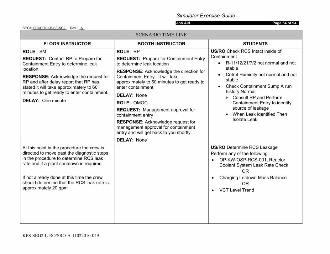
Simulator Exercise Guide Job Aid Page 54 of 94
SEG#_ROI/SRO-06-SE-SC2_ Rev ; _A_
KPS-SEG2-L-RO/SRO-A-11022010-049
SCENARIO TIME LINE
FLOOR INSTRUCTOR BOOTH INSTRUCTOR STUDENTS ROLE: SM REQUEST: Contact RP to Prepare for Containment Entry to determine leak location RESPONSE: Acknowledge the request for RP and after delay report that RP has stated it will take approximately to 60 minutes to get ready to enter containment.
DELAY: One minute
ROLE: RP REQUEST: Prepare for Containment Entry to determine leak location RESPONSE: Acknowledge the direction for Containment Entry. It will take approximately to 60 minutes to get ready to enter containment.
DELAY: None ROLE: OMOC REQUEST: Management approval for containment entry RESPONSE: Acknowledge request for management approval for containment entry and will get back to you shortly. DELAY: None
US/RO Check RCS Intact inside of Containment
• R-11/12/21/7/2 not normal and not stable
• Cntmt Humidity not normal and not stable
• Check Containment Sump A run history Normal Consult RP and Perform
Containment Entry to identify source of leakage
When Leak identified Then Isolate Leak
At this point in the procedure the crew is directed to move past the diagnostic steps in the procedure to determine RCS leak rate and if a plant shutdown is required. If not already done at this time the crew should determine that the RCS leak rate is approximately 20 gpm
US/RO Determine RCS Leakage Perform any of the following • OP-KW-OSP-RCS-001, Reactor
Coolant System Leak Rate Check OR
• Charging Letdown Mass Balance OR
• VCT Level Trend

Simulator Exercise Guide Job Aid Page 55 of 94
SEG#_ROI/SRO-06-SE-SC2_ Rev ; _A_
KPS-SEG2-L-RO/SRO-A-11022010-049
SCENARIO TIME LINE
FLOOR INSTRUCTOR BOOTH INSTRUCTOR STUDENTS
The US should hold a brief at this time to assess the situation ROLE: SM REQUEST: EAL Classification and contact management for direction on plant shutdown RESPONSE: EAL Under Evaluation and will Contact Plant Management
DELAY: None
US Determine if Plant Shutdown Required • RCS Operational leakage does not
comply with TS3.4.13 RCS Operational leakage
OR • Plant Management directs plant
shutdown Technical Specification TS 3.4.13 RCS Operational Leakage Condition A RCS operational LEAKAGE not within limits for reasons other than pressure boundary LEAKAGE or primary to secondary LEAKAGE with Required Action A.1 to reduce leakage to within limits with a completion time of 4 hours.
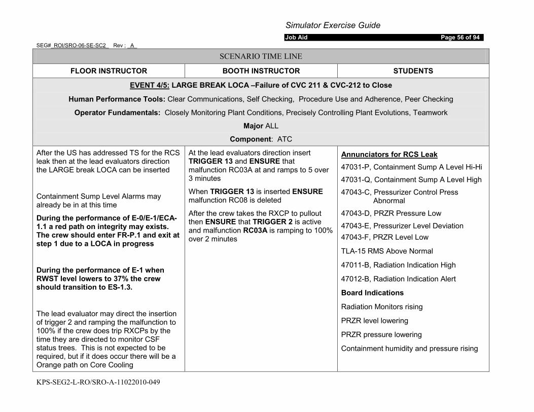
Simulator Exercise Guide Job Aid Page 56 of 94
SEG#_ROI/SRO-06-SE-SC2_ Rev ; _A_
KPS-SEG2-L-RO/SRO-A-11022010-049
SCENARIO TIME LINE
FLOOR INSTRUCTOR BOOTH INSTRUCTOR STUDENTS
EVENT 4/5:
Human Performance Tools: Clear Communications, Self Checking, Procedure Use and Adherence, Peer Checking
LARGE BREAK LOCA –Failure of CVC 211 & CVC-212 to Close
Operator Fundamentals: Closely Monitoring Plant Conditions, Precisely Controlling Plant Evolutions, Teamwork
Major ALL
Component: ATC
After the US has addressed TS for the RCS leak then at the lead evaluators direction the LARGE break LOCA can be inserted
Containment Sump Level Alarms may already be in at this time
During the performance of E-0/E-1/ECA-1.1 a red path on integrity may exists. The crew should enter FR-P.1 and exit at step 1 due to a LOCA in progress
During the performance of E-1 when RWST level lowers to 37% the crew should transition to ES-1.3.
The lead evaluator may direct the insertion of trigger 2 and ramping the malfunction to 100% if the crew does trip RXCPs by the time they are directed to monitor CSF status trees. This is not expected to be required, but if it does occur there will be a Orange path on Core Cooling
At the lead evaluators direction insert TRIGGER 13 and ENSURE that malfunction RC03A at and ramps to 5 over 3 minutes
When TRIGGER 13 is inserted ENSURE malfunction RC08 is deleted
After the crew takes the RXCP to pullout then ENSURE that TRIGGER 2 is active and malfunction RC03A is ramping to 100% over 2 minutes
47031-P, Containment Sump A Level Hi-Hi
Annunciators for RCS Leak
47031-Q, Containment Sump A Level High
47043-C, Pressurizer Control Press Abnormal
47043-D, PRZR Pressure Low
47043-E, Pressurizer Level Deviation 47043-F, PRZR Level Low
TLA-15 RMS Above Normal
47011-B, Radiation Indication High
47012-B, Radiation Indication Alert
Board Indications
Radiation Monitors rising
PRZR level lowering
PRZR pressure lowering
Containment humidity and pressure rising
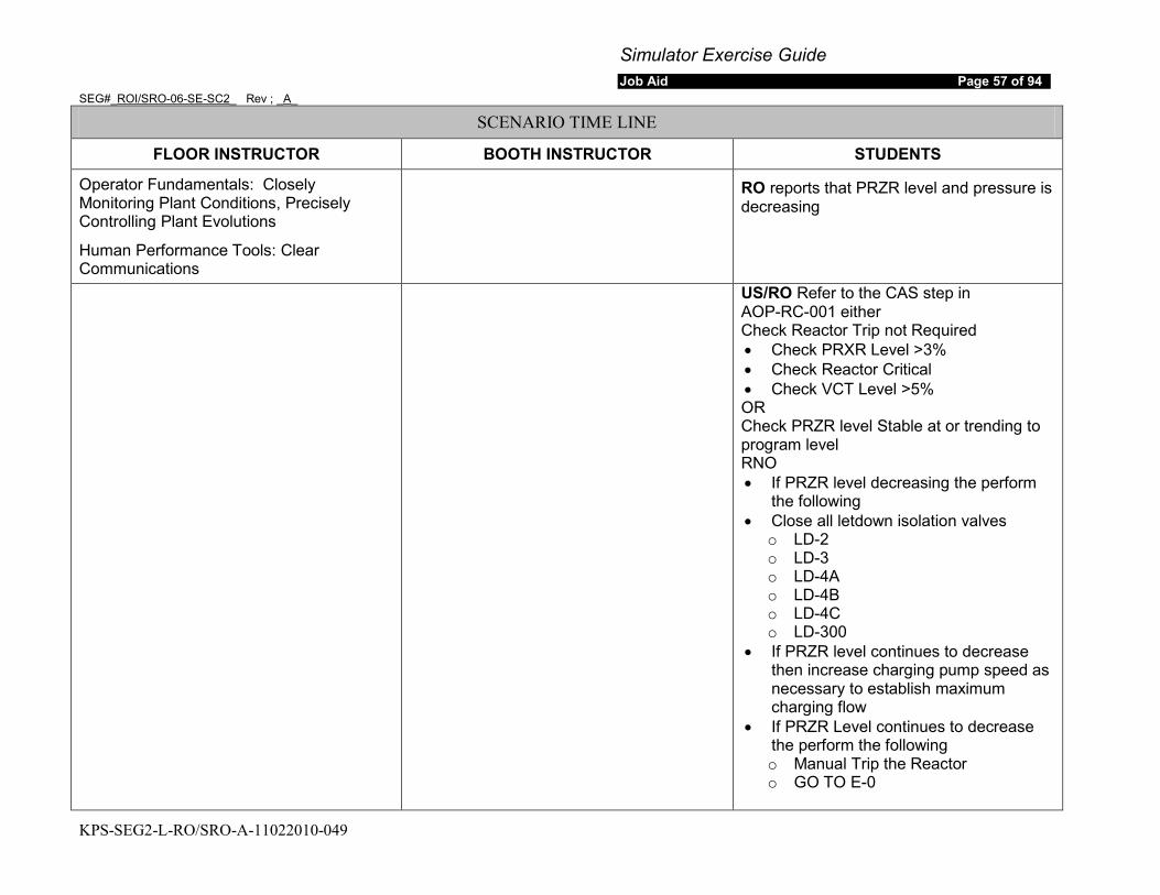
Simulator Exercise Guide Job Aid Page 57 of 94
SEG#_ROI/SRO-06-SE-SC2_ Rev ; _A_
KPS-SEG2-L-RO/SRO-A-11022010-049
SCENARIO TIME LINE
FLOOR INSTRUCTOR BOOTH INSTRUCTOR STUDENTS
Operator Fundamentals: Closely Monitoring Plant Conditions, Precisely Controlling Plant Evolutions
Human Performance Tools: Clear Communications
RO reports that PRZR level and pressure is decreasing
US/RO Refer to the CAS step in AOP-RC-001 either Check Reactor Trip not Required • Check PRXR Level >3% • Check Reactor Critical • Check VCT Level >5% OR Check PRZR level Stable at or trending to program level RNO • If PRZR level decreasing the perform
the following • Close all letdown isolation valves
o LD-2 o LD-3 o LD-4A o LD-4B o LD-4C o LD-300
• If PRZR level continues to decrease then increase charging pump speed as necessary to establish maximum charging flow
• If PRZR Level continues to decrease the perform the following o Manual Trip the Reactor o GO TO E-0
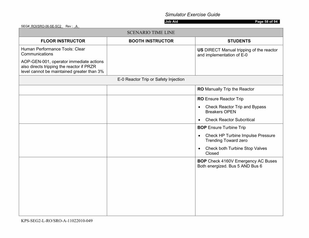
Simulator Exercise Guide Job Aid Page 58 of 94
SEG#_ROI/SRO-06-SE-SC2_ Rev ; _A_
KPS-SEG2-L-RO/SRO-A-11022010-049
SCENARIO TIME LINE
FLOOR INSTRUCTOR BOOTH INSTRUCTOR STUDENTS
Human Performance Tools: Clear Communications
AOP-GEN-001, operator immediate actions also directs tripping the reactor if PRZR level cannot be maintained greater than 3%
US DIRECT Manual tripping of the reactor and implementation of E-0
E-0 Reactor Trip or Safety Injection
RO Manually Trip the Reactor
RO Ensure Reactor Trip
• Check Reactor Trip and Bypass Breakers OPEN
• Check Reactor Subcritical
BOP Ensure Turbine Trip
• Check HP Turbine Impulse Pressure Trending Toward zero
• Check both Turbine Stop Valves Closed
BOP Check 4160V Emergency AC Buses Both energized. Bus 5 AND Bus 6
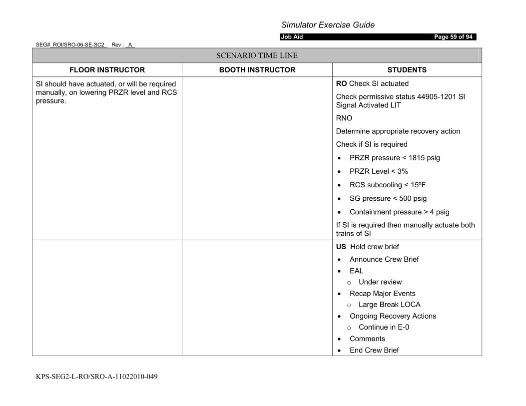
Simulator Exercise Guide Job Aid Page 59 of 94
SEG#_ROI/SRO-06-SE-SC2_ Rev ; _A_
KPS-SEG2-L-RO/SRO-A-11022010-049
SCENARIO TIME LINE
FLOOR INSTRUCTOR BOOTH INSTRUCTOR STUDENTS
SI should have actuated, or will be required manually, on lowering PRZR level and RCS pressure.
RO Check SI actuated
Check permissive status 44905-1201 SI Signal Activated LIT
RNO
Determine appropriate recovery action
Check if SI is required
• PRZR pressure < 1815 psig
• PRZR Level < 3%
• RCS subcooling < 15ºF
• SG pressure < 500 psig
• Containment pressure > 4 psig
If SI is required then manually actuate both trains of SI
US Hold crew brief
• Announce Crew Brief • EAL
o Under review • Recap Major Events
o Large Break LOCA • Ongoing Recovery Actions
o Continue in E-0 • Comments • End Crew Brief
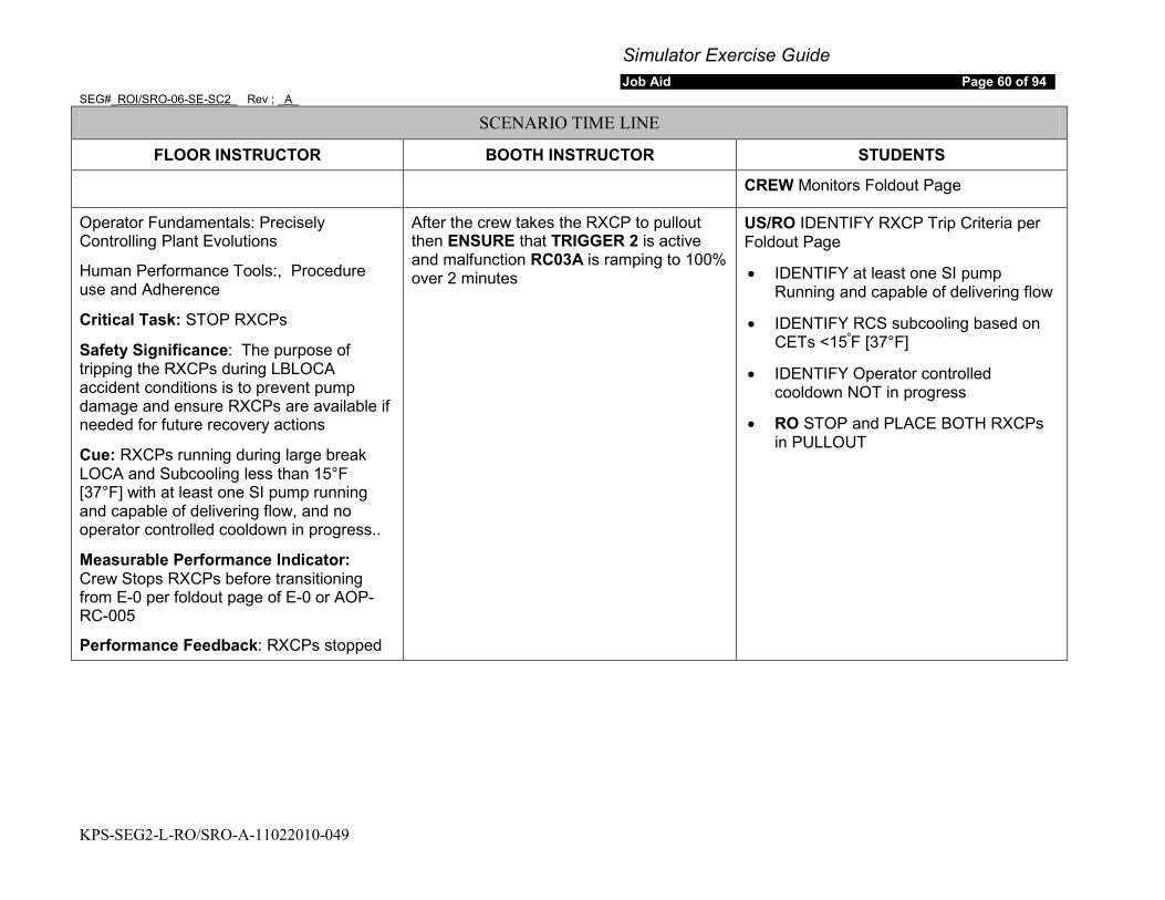
Simulator Exercise Guide Job Aid Page 60 of 94
SEG#_ROI/SRO-06-SE-SC2_ Rev ; _A_
KPS-SEG2-L-RO/SRO-A-11022010-049
SCENARIO TIME LINE
FLOOR INSTRUCTOR BOOTH INSTRUCTOR STUDENTS
CREW Monitors Foldout Page
Operator Fundamentals: Precisely Controlling Plant Evolutions
Human Performance Tools:, Procedure use and Adherence
Critical Task: STOP RXCPs
Safety Significance: The purpose of tripping the RXCPs during LBLOCA accident conditions is to prevent pump damage and ensure RXCPs are available if needed for future recovery actions
Cue: RXCPs running during large break LOCA and Subcooling less than 15°F [37°F] with at least one SI pump running and capable of delivering flow, and no operator controlled cooldown in progress..
Measurable Performance Indicator: Crew Stops RXCPs before transitioning from E-0 per foldout page of E-0 or AOP-RC-005
Performance Feedback: RXCPs stopped
After the crew takes the RXCP to pullout then ENSURE that TRIGGER 2 is active and malfunction RC03A is ramping to 100% over 2 minutes
US/RO IDENTIFY RXCP Trip Criteria per Foldout Page
• IDENTIFY at least one SI pump Running and capable of delivering flow
• IDENTIFY RCS subcooling based on CETs <15º
• IDENTIFY Operator controlled cooldown NOT in progress
F [37°F]
• RO STOP and PLACE BOTH RXCPs in PULLOUT
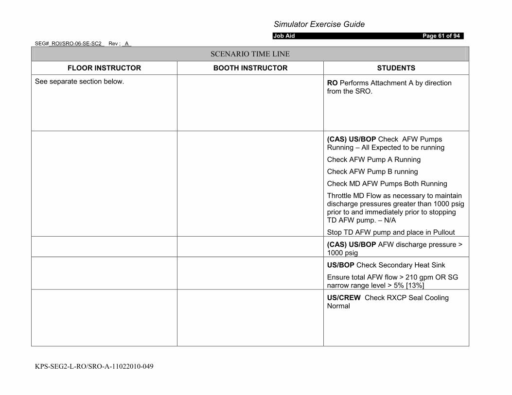
Simulator Exercise Guide Job Aid Page 61 of 94
SEG#_ROI/SRO-06-SE-SC2_ Rev ; _A_
KPS-SEG2-L-RO/SRO-A-11022010-049
SCENARIO TIME LINE
FLOOR INSTRUCTOR BOOTH INSTRUCTOR STUDENTS
See separate section below. RO Performs Attachment A by direction from the SRO.
(CAS) US/BOP Check AFW Pumps Running – All Expected to be running
Check AFW Pump A Running
Check AFW Pump B running
Check MD AFW Pumps Both Running
Throttle MD Flow as necessary to maintain discharge pressures greater than 1000 psig prior to and immediately prior to stopping TD AFW pump. – N/A
Stop TD AFW pump and place in Pullout (CAS) US/BOP AFW discharge pressure >
1000 psig US/BOP Check Secondary Heat Sink
Ensure total AFW flow > 210 gpm OR SG narrow range level > 5% [13%]
US/CREW Check RXCP Seal Cooling Normal
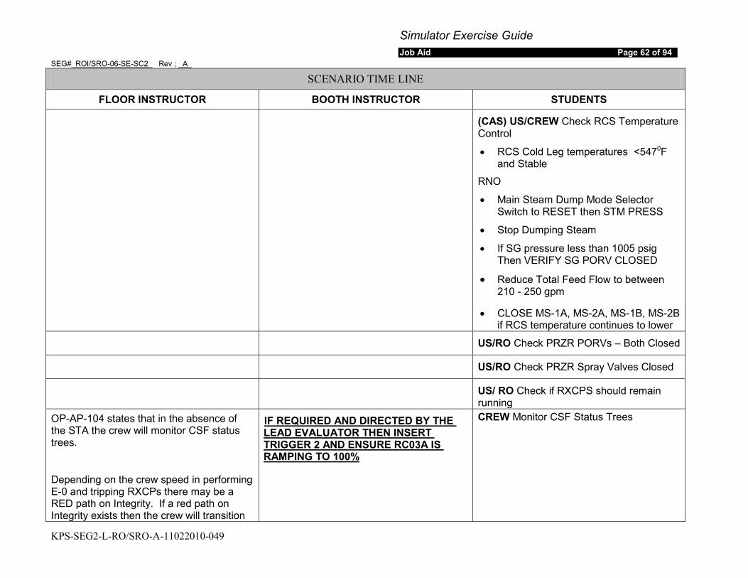
Simulator Exercise Guide Job Aid Page 62 of 94
SEG#_ROI/SRO-06-SE-SC2_ Rev ; _A_
KPS-SEG2-L-RO/SRO-A-11022010-049
SCENARIO TIME LINE
FLOOR INSTRUCTOR BOOTH INSTRUCTOR STUDENTS
(CAS) US/CREW Check RCS Temperature Control
• RCS Cold Leg temperatures <5470
RNO
F and Stable
• Main Steam Dump Mode Selector Switch to RESET then STM PRESS
• Stop Dumping Steam
• If SG pressure less than 1005 psig Then VERIFY SG PORV CLOSED
• Reduce Total Feed Flow to between 210 - 250 gpm
• CLOSE MS-1A, MS-2A, MS-1B, MS-2B if RCS temperature continues to lower
US/RO Check PRZR PORVs – Both Closed
US/RO Check PRZR Spray Valves Closed
US/ RO Check if RXCPS should remain running
OP-AP-104 states that in the absence of the STA the crew will monitor CSF status trees.
Depending on the crew speed in performing E-0 and tripping RXCPs there may be a RED path on Integrity. If a red path on Integrity exists then the crew will transition
CREW Monitor CSF Status Trees IF REQUIRED AND DIRECTED BY THE LEAD EVALUATOR THEN INSERT TRIGGER 2 AND ENSURE RC03A IS RAMPING TO 100%
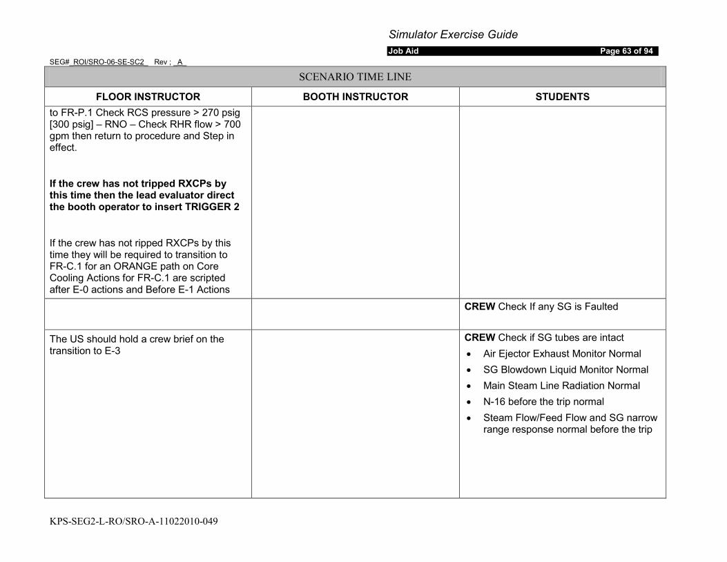
Simulator Exercise Guide Job Aid Page 63 of 94
SEG#_ROI/SRO-06-SE-SC2_ Rev ; _A_
KPS-SEG2-L-RO/SRO-A-11022010-049
SCENARIO TIME LINE
FLOOR INSTRUCTOR BOOTH INSTRUCTOR STUDENTS to FR-P.1 Check RCS pressure > 270 psig [300 psig] – RNO – Check RHR flow > 700 gpm then return to procedure and Step in effect.
If the crew has not tripped RXCPs by this time then the lead evaluator direct the booth operator to insert TRIGGER 2
If the crew has not ripped RXCPs by this time they will be required to transition to FR-C.1 for an ORANGE path on Core Cooling Actions for FR-C.1 are scripted after E-0 actions and Before E-1 Actions
CREW Check If any SG is Faulted
The US should hold a crew brief on the transition to E-3
CREW Check if SG tubes are intact • Air Ejector Exhaust Monitor Normal • SG Blowdown Liquid Monitor Normal • Main Steam Line Radiation Normal • N-16 before the trip normal • Steam Flow/Feed Flow and SG narrow
range response normal before the trip
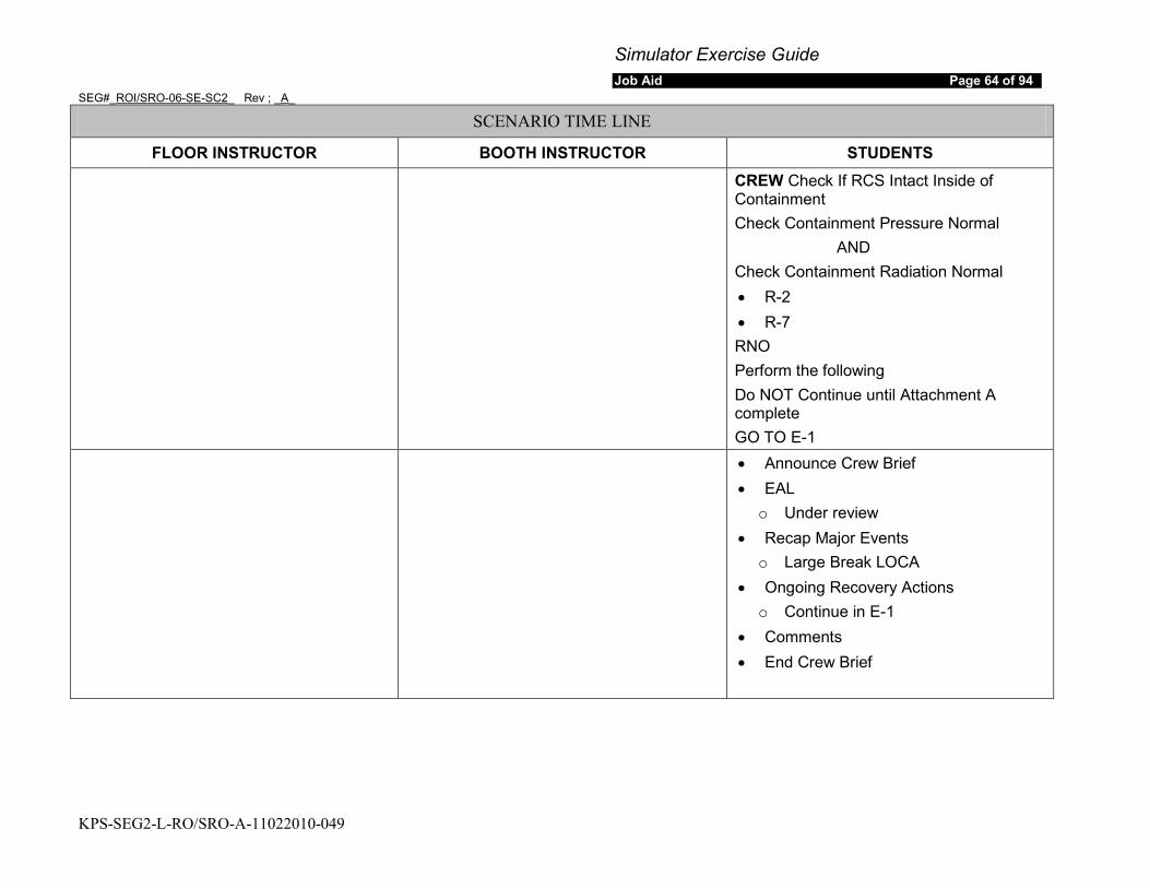
Simulator Exercise Guide Job Aid Page 64 of 94
SEG#_ROI/SRO-06-SE-SC2_ Rev ; _A_
KPS-SEG2-L-RO/SRO-A-11022010-049
SCENARIO TIME LINE
FLOOR INSTRUCTOR BOOTH INSTRUCTOR STUDENTS
CREW Check If RCS Intact Inside of Containment Check Containment Pressure Normal
AND Check Containment Radiation Normal • R-2 • R-7 RNO Perform the following Do NOT Continue until Attachment A complete GO TO E-1
• Announce Crew Brief • EAL
o Under review • Recap Major Events
o Large Break LOCA • Ongoing Recovery Actions
o Continue in E-1 • Comments • End Crew Brief
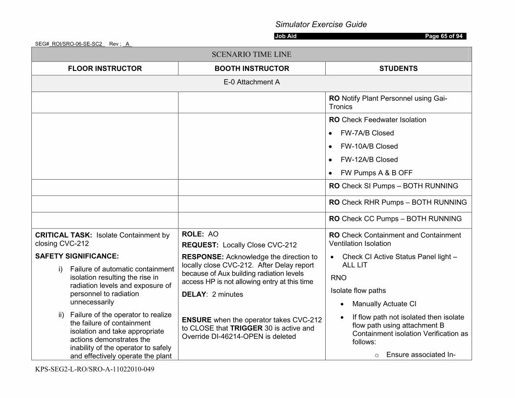
Simulator Exercise Guide Job Aid Page 65 of 94
SEG#_ROI/SRO-06-SE-SC2_ Rev ; _A_
KPS-SEG2-L-RO/SRO-A-11022010-049
SCENARIO TIME LINE
FLOOR INSTRUCTOR BOOTH INSTRUCTOR STUDENTS
E-0 Attachment A
RO Notify Plant Personnel using Gai-Tronics
RO Check Feedwater Isolation
• FW-7A/B Closed
• FW-10A/B Closed
• FW-12A/B Closed
• FW Pumps A & B OFF
RO Check SI Pumps – BOTH RUNNING
RO Check RHR Pumps – BOTH RUNNING
RO Check CC Pumps – BOTH RUNNING
CRITICAL TASK: Isolate Containment by closing CVC-212
SAFETY SIGNIFICANCE:
i) Failure of automatic containment isolation resulting the rise in radiation levels and exposure of personnel to radiation unnecessarily
ii) Failure of the operator to realize the failure of containment isolation and take appropriate actions demonstrates the inability of the operator to safely and effectively operate the plant
ROLE: AO REQUEST: Locally Close CVC-212 RESPONSE: Acknowledge the direction to locally close CVC-212. After Delay report because of Aux building radiation levels access HP is not allowing entry at this time
DELAY: 2 minutes
ENSURE when the operator takes CVC-212 to CLOSE that TRIGGER 30 is active and Override DI-46214-OPEN is deleted
RO Check Containment and Containment Ventilation Isolation
• Check CI Active Status Panel light – ALL LIT
RNO
Isolate flow paths
• Manually Actuate CI
• If flow path not isolated then isolate flow path using attachment B Containment isolation Verification as follows:
o Ensure associated In-
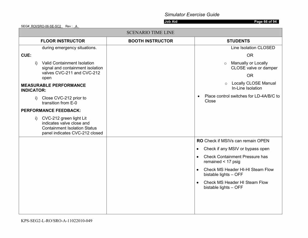
Simulator Exercise Guide Job Aid Page 66 of 94
SEG#_ROI/SRO-06-SE-SC2_ Rev ; _A_
KPS-SEG2-L-RO/SRO-A-11022010-049
SCENARIO TIME LINE
FLOOR INSTRUCTOR BOOTH INSTRUCTOR STUDENTS during emergency situations.
CUE:
i) Valid Containment Isolation signal and containment isolation valves CVC-211 and CVC-212 open
MEASURABLE PERFORMANCE INDICATOR:
i) Close CVC-212 prior to transition from E-0
PERFORMANCE FEEDBACK:
i) CVC-212 green light Lit indicates valve close and Containment Isolation Status panel indicates CVC-212 closed
Line Isolation CLOSED
OR
o Manually or Locally CLOSE valve or damper
OR
o Locally CLOSE Manual In-Line Isolation
• Place control switches for LD-4A/B/C to Close
RO Check if MSIVs can remain OPEN
• Check if any MSIV or bypass open
• Check Containment Pressure has remained < 17 psig
• Check MS Header HI-HI Steam Flow bistable lights – OFF
• Check MS Header HI Steam Flow bistable lights – OFF
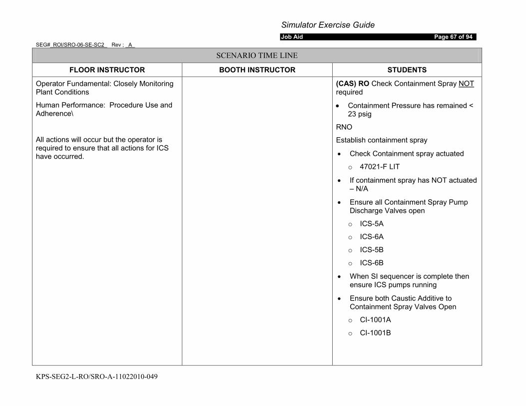
Simulator Exercise Guide Job Aid Page 67 of 94
SEG#_ROI/SRO-06-SE-SC2_ Rev ; _A_
KPS-SEG2-L-RO/SRO-A-11022010-049
SCENARIO TIME LINE
FLOOR INSTRUCTOR BOOTH INSTRUCTOR STUDENTS
Operator Fundamental: Closely Monitoring Plant Conditions
Human Performance: Procedure Use and Adherence\
All actions will occur but the operator is required to ensure that all actions for ICS have occurred.
(CAS) RO Check Containment Spray NOT
• Containment Pressure has remained < 23 psig
required
RNO
Establish containment spray
• Check Containment spray actuated
o 47021-F LIT
• If containment spray has NOT actuated – N/A
• Ensure all Containment Spray Pump Discharge Valves open
o ICS-5A
o ICS-6A
o ICS-5B
o ICS-6B
• When SI sequencer is complete then ensure ICS pumps running
• Ensure both Caustic Additive to Containment Spray Valves Open
o CI-1001A
o CI-1001B
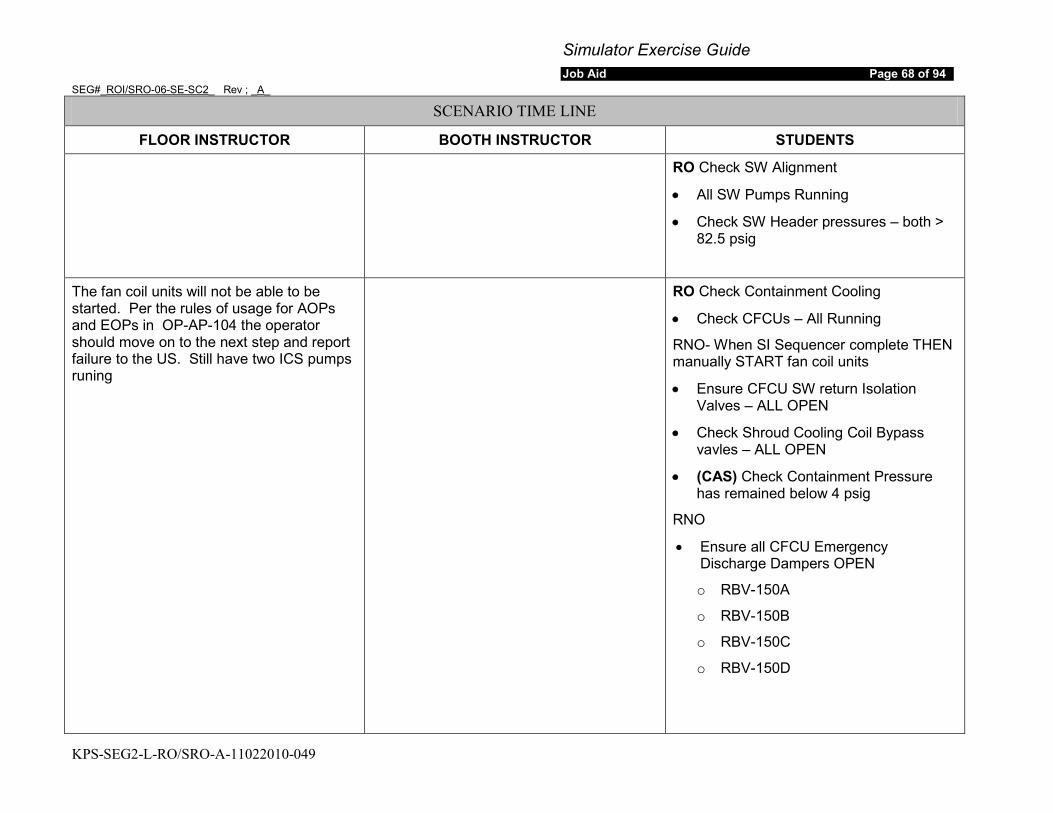
Simulator Exercise Guide Job Aid Page 68 of 94
SEG#_ROI/SRO-06-SE-SC2_ Rev ; _A_
KPS-SEG2-L-RO/SRO-A-11022010-049
SCENARIO TIME LINE
FLOOR INSTRUCTOR BOOTH INSTRUCTOR STUDENTS
RO Check SW Alignment
• All SW Pumps Running
• Check SW Header pressures – both > 82.5 psig
The fan coil units will not be able to be started. Per the rules of usage for AOPs and EOPs in OP-AP-104 the operator should move on to the next step and report failure to the US. Still have two ICS pumps runing
RO Check Containment Cooling
• Check CFCUs – All Running
RNO- When SI Sequencer complete THEN manually START fan coil units
• Ensure CFCU SW return Isolation Valves – ALL OPEN
• Check Shroud Cooling Coil Bypass vavles – ALL OPEN
• (CAS) Check Containment Pressure has remained below 4 psig
RNO
• Ensure all CFCU Emergency Discharge Dampers OPEN
o RBV-150A
o RBV-150B
o RBV-150C
o RBV-150D

Simulator Exercise Guide Job Aid Page 69 of 94
SEG#_ROI/SRO-06-SE-SC2_ Rev ; _A_
KPS-SEG2-L-RO/SRO-A-11022010-049
SCENARIO TIME LINE
FLOOR INSTRUCTOR BOOTH INSTRUCTOR STUDENTS
RO Verify Aux Building Special Ventilation
• Check Annunciator Zone SV BNDRY Damper not Closed – Clear (47052-G)
• Check Zone SV Fans - ALL RUNNING
RO Check Si Active Status Panel Lights – ALL LIT
RO Check SI Flow
• Check RCS Pressure < 2000 psig
• Check SI pumps flow indicated on FI-925
• Check RCS pressure < 270 psig [300 psig]
• Check RHR pump Flow indicated on FI-626 for pump A and FI-928 for pump B
RO Return procedure and step in effect
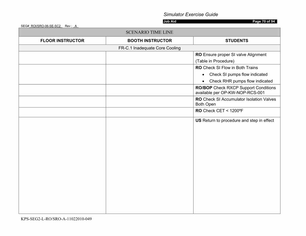
Simulator Exercise Guide Job Aid Page 70 of 94
SEG#_ROI/SRO-06-SE-SC2_ Rev ; _A_
KPS-SEG2-L-RO/SRO-A-11022010-049
SCENARIO TIME LINE
FLOOR INSTRUCTOR BOOTH INSTRUCTOR STUDENTS FR-C.1 Inadequate Core Cooling
RO Ensure proper SI valve Alignment (Table in Procedure)
RO Check SI Flow in Both Trains • Check SI pumps flow indicated • Check RHR pumps flow indicated
RO/BOP Check RXCP Support Conditions available per OP-KW-NOP-RCS-001
RO Check SI Accumulator Isolation Valves Both Open
RO Check CET < 1200ºF
US Return to procedure and step in effect
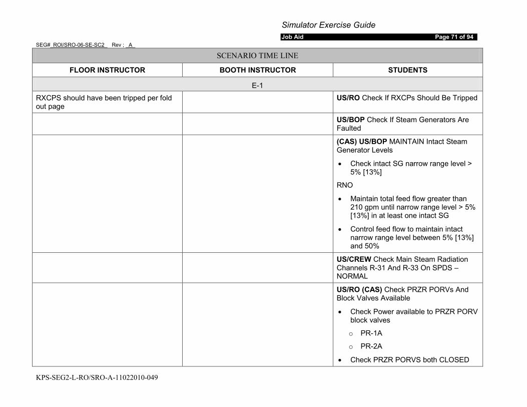
Simulator Exercise Guide Job Aid Page 71 of 94
SEG#_ROI/SRO-06-SE-SC2_ Rev ; _A_
KPS-SEG2-L-RO/SRO-A-11022010-049
SCENARIO TIME LINE
FLOOR INSTRUCTOR BOOTH INSTRUCTOR STUDENTS
E-1
RXCPS should have been tripped per fold out page
US/RO Check If RXCPs Should Be Tripped
US/BOP Check If Steam Generators Are Faulted
(CAS) US/BOP MAINTAIN Intact Steam Generator Levels
• Check intact SG narrow range level > 5% [13%]
RNO
• Maintain total feed flow greater than 210 gpm until narrow range level > 5% [13%] in at least one intact SG
• Control feed flow to maintain intact narrow range level between 5% [13%] and 50%
US/CREW Check Main Steam Radiation Channels R-31 And R-33 On SPDS – NORMAL
US/RO (CAS) Check PRZR PORVs And Block Valves Available
• Check Power available to PRZR PORV block valves
o PR-1A
o PR-2A
• Check PRZR PORVS both CLOSED
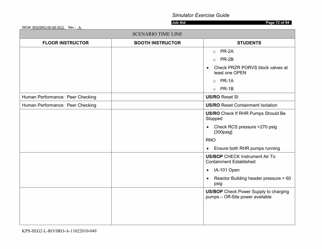
Simulator Exercise Guide Job Aid Page 72 of 94
SEG#_ROI/SRO-06-SE-SC2_ Rev ; _A_
KPS-SEG2-L-RO/SRO-A-11022010-049
SCENARIO TIME LINE
FLOOR INSTRUCTOR BOOTH INSTRUCTOR STUDENTS
o PR-2A
o PR-2B
• Check PRZR PORVS block valves at least one OPEN
o PR-1A
o PR-1B
Human Performance: Peer Checking US/RO Reset SI
Human Performance: Peer Checking US/RO Reset Containment Isolation
US/RO Check If RHR Pumps Should Be Stopped
• Check RCS pressure >270 psig [300psig]
RNO
• Ensure both RHR pumps running
US/BOP CHECK Instrument Air To Containment Established
• IA-101 Open
• Reactor Building header pressure > 60 psig
US/BOP Check Power Supply to charging pumps – Off-Site power available

Simulator Exercise Guide Job Aid Page 73 of 94
SEG#_ROI/SRO-06-SE-SC2_ Rev ; _A_
KPS-SEG2-L-RO/SRO-A-11022010-049
SCENARIO TIME LINE
FLOOR INSTRUCTOR BOOTH INSTRUCTOR STUDENTS
US/RO Check Charging Flow Established
• Start two charging pumps and establish charging flow to maintain PRZR level > 3% [15%]
RO/BOP checks each sub-step and determines step requirement is NOT met.
US/RO Check If SI Should Be Terminated
CHECK RCS subcooling based on core exit thermocouples - > 15°F [60°F]
CHECK RCS pressure:
• Greater than 2000 psig
• Stable or Increasing
AND
RO reports conditions not satisfied
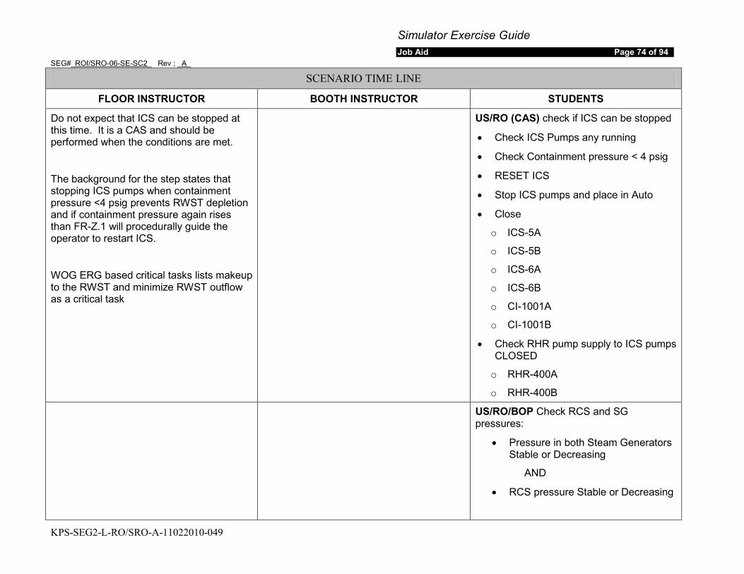
Simulator Exercise Guide Job Aid Page 74 of 94
SEG#_ROI/SRO-06-SE-SC2_ Rev ; _A_
KPS-SEG2-L-RO/SRO-A-11022010-049
SCENARIO TIME LINE
FLOOR INSTRUCTOR BOOTH INSTRUCTOR STUDENTS
Do not expect that ICS can be stopped at this time. It is a CAS and should be performed when the conditions are met.
The background for the step states that stopping ICS pumps when containment pressure <4 psig prevents RWST depletion and if containment pressure again rises than FR-Z.1 will procedurally guide the operator to restart ICS.
WOG ERG based critical tasks lists makeup to the RWST and minimize RWST outflow as a critical task
US/RO (CAS) check if ICS can be stopped
• Check ICS Pumps any running
• Check Containment pressure < 4 psig
• RESET ICS
• Stop ICS pumps and place in Auto
• Close
o ICS-5A
o ICS-5B
o ICS-6A
o ICS-6B
o CI-1001A
o CI-1001B
• Check RHR pump supply to ICS pumps CLOSED
o RHR-400A
o RHR-400B
US/RO/BOP Check RCS and SG pressures:
• Pressure in both Steam Generators Stable or Decreasing
AND
• RCS pressure Stable or Decreasing
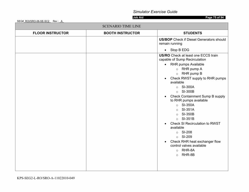
Simulator Exercise Guide Job Aid Page 75 of 94
SEG#_ROI/SRO-06-SE-SC2_ Rev ; _A_
KPS-SEG2-L-RO/SRO-A-11022010-049
SCENARIO TIME LINE
FLOOR INSTRUCTOR BOOTH INSTRUCTOR STUDENTS
US/BOP Check if Diesel Generators should remain running
• Stop B EDG
US/RO Check at least one ECCS train capable of Sump Recirculation
• RHR pumps Available o RHR pump A o RHR pump B
• Check RWST supply to RHR pumps available
o SI-300A o SI-300B
• Check Containment Sump B supply to RHR pumps available
o SI-350A o SI-351A o SI-350B o SI-351B
• Check SI Recirculation to RWST available
o SI-208 o SI-209
• Check RHR heat exchanger flow control valves available
o RHR-8A o RHR-8B
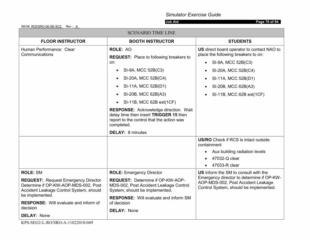
Simulator Exercise Guide Job Aid Page 76 of 94
SEG#_ROI/SRO-06-SE-SC2_ Rev ; _A_
KPS-SEG2-L-RO/SRO-A-11022010-049
SCENARIO TIME LINE
FLOOR INSTRUCTOR BOOTH INSTRUCTOR STUDENTS
Human Performance: Clear Communications
ROLE: AO
REQUEST: Place to following breakers to on:
• SI-9A, MCC 52B(C3)
• SI-20A, MCC 52B(C4)
• SI-11A, MCC 52B(D1)
• SI-20B, MCC 62B(A3)
• SI-11B, MCC 62B ext(1CF)
RESPONSE: Acknowledge direction. Wait delay time then insert TRIGGER 15 then report to the control that the action was completed.
DELAY: 8 minutes
US direct board operator to contact NAO to place the following breakers to on:
• SI-9A, MCC 52B(C3)
• SI-20A, MCC 52B(C4)
• SI-11A, MCC 52B(D1)
• SI-20B, MCC 62B(A3)
• SI-11B, MCC 62B ext(1CF)
US/RO Check if RCS is intact outside containment
• Aux building radiation levels • 47032-Q clear • 47033-R clear
ROLE: SM
REQUEST: Request Emergency Director Determine if OP-KW-AOP-MDS-002, Post Accident Leakage Control System, should be implemented.
RESPONSE: Will evaluate and inform of decision
DELAY: None
ROLE: Emergency Director
REQUEST: Determine if OP-KW-AOP-MDS-002, Post Accident Leakage Control System, should be implemented.
RESPONSE: Will evaluate and inform SM of decision
DELAY: None
US inform the SM to consult with the Emergency director to determine if OP-KW-AOP-MDS-002, Post Accident Leakage Control System, should be implemented.
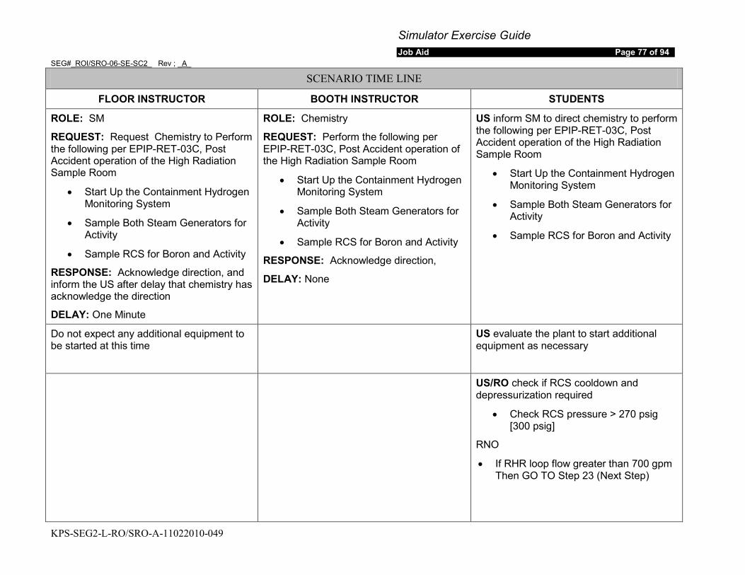
Simulator Exercise Guide Job Aid Page 77 of 94
SEG#_ROI/SRO-06-SE-SC2_ Rev ; _A_
KPS-SEG2-L-RO/SRO-A-11022010-049
SCENARIO TIME LINE
FLOOR INSTRUCTOR BOOTH INSTRUCTOR STUDENTS
ROLE: SM
REQUEST: Request Chemistry to Perform the following per EPIP-RET-03C, Post Accident operation of the High Radiation Sample Room
• Start Up the Containment Hydrogen Monitoring System
• Sample Both Steam Generators for Activity
• Sample RCS for Boron and Activity
RESPONSE: Acknowledge direction, and inform the US after delay that chemistry has acknowledge the direction
DELAY: One Minute
ROLE: Chemistry
REQUEST: Perform the following per EPIP-RET-03C, Post Accident operation of the High Radiation Sample Room
• Start Up the Containment Hydrogen Monitoring System
• Sample Both Steam Generators for Activity
• Sample RCS for Boron and Activity
RESPONSE: Acknowledge direction,
DELAY: None
US inform SM to direct chemistry to perform the following per EPIP-RET-03C, Post Accident operation of the High Radiation Sample Room
• Start Up the Containment Hydrogen Monitoring System
• Sample Both Steam Generators for Activity
• Sample RCS for Boron and Activity
Do not expect any additional equipment to be started at this time
US evaluate the plant to start additional equipment as necessary
US/RO check if RCS cooldown and depressurization required
• Check RCS pressure > 270 psig [300 psig]
RNO
• If RHR loop flow greater than 700 gpm Then GO TO Step 23 (Next Step)
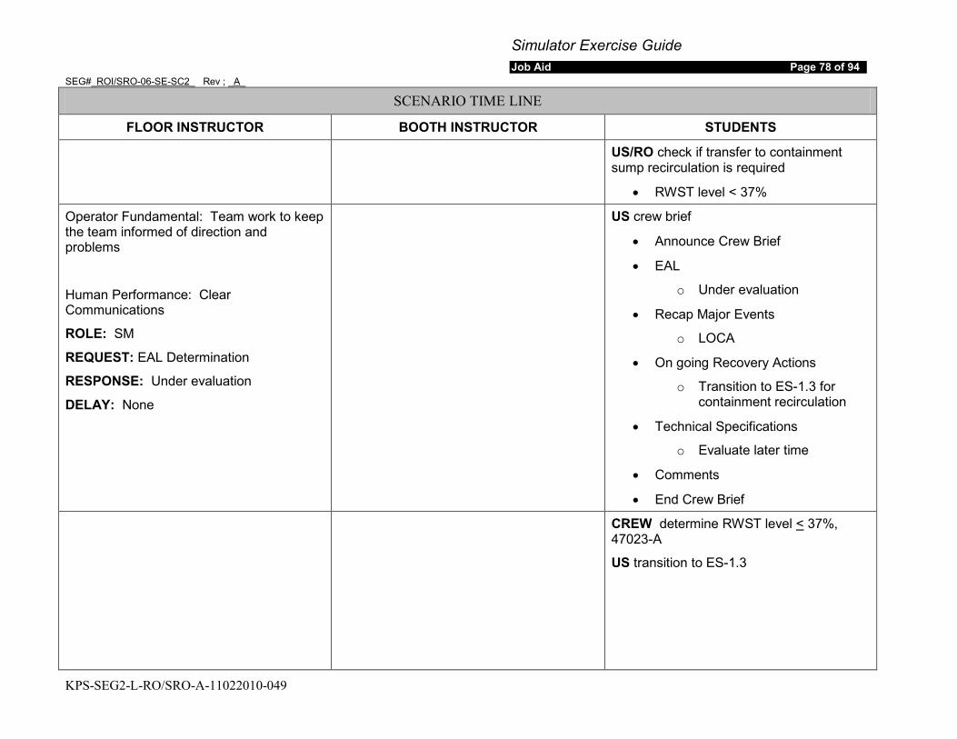
Simulator Exercise Guide Job Aid Page 78 of 94
SEG#_ROI/SRO-06-SE-SC2_ Rev ; _A_
KPS-SEG2-L-RO/SRO-A-11022010-049
SCENARIO TIME LINE
FLOOR INSTRUCTOR BOOTH INSTRUCTOR STUDENTS
US/RO check if transfer to containment sump recirculation is required
• RWST level < 37%
Operator Fundamental: Team work to keep the team informed of direction and problems
Human Performance: Clear Communications
ROLE: SM
REQUEST: EAL Determination
RESPONSE: Under evaluation
DELAY: None
US crew brief
• Announce Crew Brief
• EAL
o Under evaluation
• Recap Major Events
o LOCA
• On going Recovery Actions
o Transition to ES-1.3 for containment recirculation
• Technical Specifications
o Evaluate later time
• Comments
• End Crew Brief
CREW determine RWST level < 37%, 47023-A
US transition to ES-1.3

Simulator Exercise Guide Job Aid Page 79 of 94
SEG#_ROI/SRO-06-SE-SC2_ Rev ; _A_
KPS-SEG2-L-RO/SRO-A-11022010-049
SCENARIO TIME LINE
FLOOR INSTRUCTOR BOOTH INSTRUCTOR STUDENTS
ES-1.3
Note: Critical task to stop any pumps taking a suction from the RWST when receive the RWST Low Low Level Alarm 47023-A.
Depending upon the speed of the crew this may occur prior to failure of SI-350A and SI-350B to open. The critical task is scripted in ECA-1.1 portion of the SEG
US/RO check containment Wide range level > 2 feet
RO reset SI
RO reset ICS
WOG ERG based critical tasks lists makeup to the RWST and minimize RWST outflow as a critical task
US/RO establish one train of injection • Check train A injection flow:
o SI pump A running and pump amps indicate flow
OR o RHR pump A running and
flow indicated FI-626 • Stop SI pump B • Stop RHR pump B
US/RO (CAS) check RCS pressure < 2000 psig
Human Performance: Self Checking and Peer Checking
RO close both SI recirculation to RWST valves
• SI-208
• SI-209
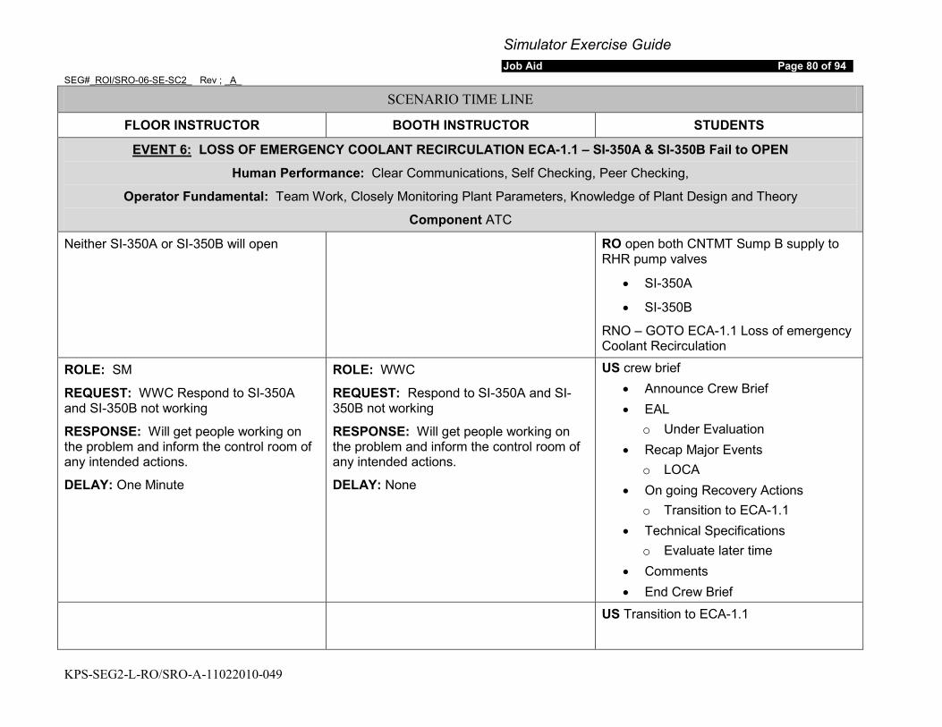
Simulator Exercise Guide Job Aid Page 80 of 94
SEG#_ROI/SRO-06-SE-SC2_ Rev ; _A_
KPS-SEG2-L-RO/SRO-A-11022010-049
SCENARIO TIME LINE
FLOOR INSTRUCTOR BOOTH INSTRUCTOR STUDENTS
EVENT 6:
Human Performance: Clear Communications, Self Checking, Peer Checking,
LOSS OF EMERGENCY COOLANT RECIRCULATION ECA-1.1 – SI-350A & SI-350B Fail to OPEN
Operator Fundamental: Team Work, Closely Monitoring Plant Parameters, Knowledge of Plant Design and Theory
Component ATC
Neither SI-350A or SI-350B will open RO open both CNTMT Sump B supply to RHR pump valves
• SI-350A
• SI-350B
RNO – GOTO ECA-1.1 Loss of emergency Coolant Recirculation
ROLE: SM
REQUEST: WWC Respond to SI-350A and SI-350B not working
RESPONSE: Will get people working on the problem and inform the control room of any intended actions.
DELAY: One Minute
ROLE: WWC
REQUEST: Respond to SI-350A and SI-350B not working
RESPONSE: Will get people working on the problem and inform the control room of any intended actions.
DELAY: None
US crew brief • Announce Crew Brief • EAL
o Under Evaluation • Recap Major Events
o LOCA • On going Recovery Actions
o Transition to ECA-1.1 • Technical Specifications
o Evaluate later time • Comments • End Crew Brief
US Transition to ECA-1.1

Simulator Exercise Guide Job Aid Page 81 of 94
SEG#_ROI/SRO-06-SE-SC2_ Rev ; _A_
KPS-SEG2-L-RO/SRO-A-11022010-049
SCENARIO TIME LINE
FLOOR INSTRUCTOR BOOTH INSTRUCTOR STUDENTS
ECA-1.1 Loss of Emergency Coolant Recirculation
US/RO (CAS) check RHR pumps not cavitating
ROLE: SM . . . REQUEST: Dispatch personnel as necessary to restore Emergency Coolant Restoration equipment RESPONSE: Personnel are dispatched. DELAY: None Note: No action will be successful prior to the completion of the scenario.
ROLE: WWC/TSC/ED/NAO . . . REQUEST: Dispatch personnel as necessary to restore Emergency Coolant Restoration equipment RESPONSE: Personnel are dispatched. Note: No action will be successful prior to the completion of the scenario. DELAY: None
US inform the SM to dispatch personnel as necessary to restore Emergency Coolant Restoration equipment
US/RO check if RHR system should be de-pressurized:
• Check Containment Sump Supply to RHR any closed
o SI-350A o SI-351A o SI-350B o SI-351B
• Check RHR Pump Discharge pressure > 450 psig
RNO GO TO next step (Step 4)
US/RO check idle RWST/SI train aligned for sump recirculation:
• Verify idle train containment sump B supply to RHR pump OPEN
o SI-350A o SI-351A o SI-350B o SI-351B
RNO -GO TO Step 6
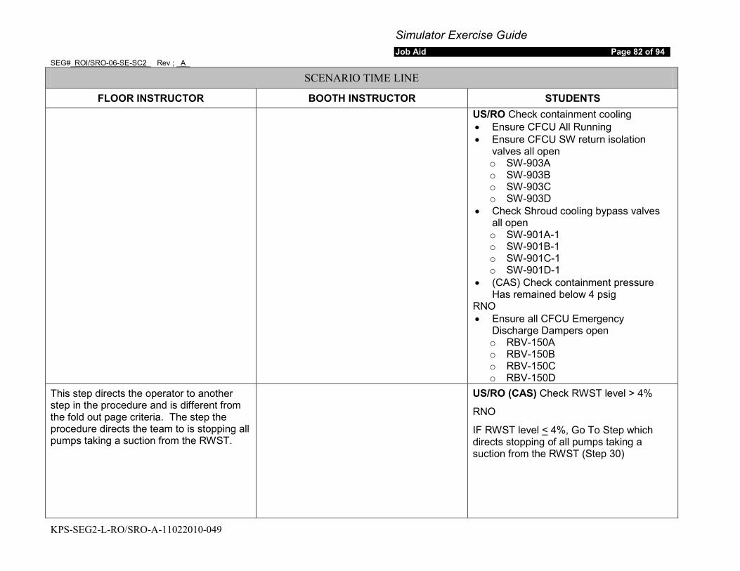
Simulator Exercise Guide Job Aid Page 82 of 94
SEG#_ROI/SRO-06-SE-SC2_ Rev ; _A_
KPS-SEG2-L-RO/SRO-A-11022010-049
SCENARIO TIME LINE
FLOOR INSTRUCTOR BOOTH INSTRUCTOR STUDENTS
US/RO Check containment cooling • Ensure CFCU All Running • Ensure CFCU SW return isolation
valves all open o SW-903A o SW-903B o SW-903C o SW-903D
• Check Shroud cooling bypass valves all open o SW-901A-1 o SW-901B-1 o SW-901C-1 o SW-901D-1
• (CAS) Check containment pressure Has remained below 4 psig
RNO • Ensure all CFCU Emergency
Discharge Dampers open o RBV-150A o RBV-150B o RBV-150C o RBV-150D
This step directs the operator to another step in the procedure and is different from the fold out page criteria. The step the procedure directs the team to is stopping all pumps taking a suction from the RWST.
US/RO (CAS) Check RWST level > 4%
RNO
IF RWST level < 4%, Go To Step which directs stopping of all pumps taking a suction from the RWST (Step 30)
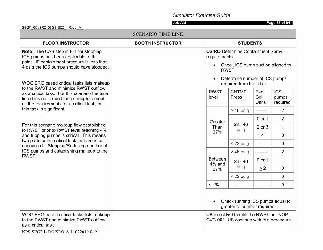
Simulator Exercise Guide Job Aid Page 83 of 94
SEG#_ROI/SRO-06-SE-SC2_ Rev ; _A_
KPS-SEG2-L-RO/SRO-A-11022010-049
SCENARIO TIME LINE
FLOOR INSTRUCTOR BOOTH INSTRUCTOR STUDENTS
Note: The CAS step in E-1 for stopping ICS pumps has been applicable to this point. IF containment pressure is less than 4 psig the ICS pumps should have stopped.
WOG ERG based critical tasks lists makeup to the RWST and minimize RWST outflow as a critical task. For this scenario the time line does not extend long enough to meet all the requirements for a critical task, but this task is significant.
For this scenario makeup flow established to RWST prior to RWST level reaching 4% and tripping pumps is critical. This means two parts to the critical task that are inter connected – Stopping/Reducing number of ICS pumps and establishing makeup to the RWST.
US/RO Determine Containment Spray requirements
• Check ICS pump suction aligned to RWST
• Determine number of ICS pumps required from the table
RWST level
CNTMT Press
Fan Coil Units
ICS pumps required
Greater Than 37%
> 46 psig -------- 2
23 - 46 psig
0 or 1 2
2 or 3 1
4 0
< 23 psig -------- 0
Between 4% and
37%
> 46 psig -------- 2
23 - 46 psig
0 or 1 1
> 2 0
< 23 psig -------- 0
< 4% ------------- --------- 0
• Check running ICS pumps equal to greater to number required
WOG ERG based critical tasks lists makeup to the RWST and minimize RWST outflow as a critical task
US direct RO to refill the RWST per NOP-CVC-001- US continue with this procedure
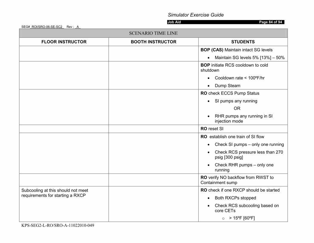
Simulator Exercise Guide Job Aid Page 84 of 94
SEG#_ROI/SRO-06-SE-SC2_ Rev ; _A_
KPS-SEG2-L-RO/SRO-A-11022010-049
SCENARIO TIME LINE
FLOOR INSTRUCTOR BOOTH INSTRUCTOR STUDENTS
BOP (CAS) Maintain intact SG levels
• Maintain SG levels 5% [13%] – 50%
BOP initiate RCS cooldown to cold shutdown
• Cooldown rate < 100ºF/hr
• Dump Steam
RO check ECCS Pump Status
• SI pumps any running
OR
• RHR pumps any running in SI injection mode
RO reset SI
RO establish one train of SI flow
• Check SI pumps – only one running
• Check RCS pressure less than 270 psig [300 psig]
• Check RHR pumps – only one running
RO verify NO backflow from RWST to Containment sump
Subcooling at this should not meet requirements for starting a RXCP
RO check if one RXCP should be started
• Both RXCPs stopped
• Check RCS subcooling based on core CETs
o > 15ºF [60ºF]
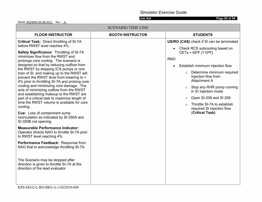
Simulator Exercise Guide Job Aid Page 85 of 94
SEG#_ROI/SRO-06-SE-SC2_ Rev ; _A_
KPS-SEG2-L-RO/SRO-A-11022010-049
SCENARIO TIME LINE
FLOOR INSTRUCTOR BOOTH INSTRUCTOR STUDENTS
Critical Task: Direct throttling of SI-7A before RWST level reaches 4%.
Safety Significance: Throttling of SI-7A minimizes flow from the RWST and prolongs core cooling. The scenario is designed so that by reducing outflow from the RWST by stopping ICS pumps or one train of SI, and making up to the RWST will prevent the RWST level from lowering to < 4% prior to throttling SI-7A and prolong core cooling and minimizing core damage. The acts of minimizing outflow from the RWST and establishing makeup to the RWST are part of a critical task to maximize length of time the RWST volume is available for core cooling.
Cue: Loss of containment sump recirculation as indicated by SI-350A ans SI-350B not opening.
Measurable Performance Indicator: Operator directs NAO to throttle SI-7A prior to RWST level reaching 4%
Performance Feedback: Response from NAO that to acknowledge throttling SI-7A.
The Scenario may be stopped after direction is given to throttle SI-7A at the direction of the lead evaluator
US/RO (CAS) check if SI can be terminated
• Check RCS subcooling based on CETs > 65ºF [110ºF]
RNO
• Establish minimum injection flow
o Determine minimum required injection flow from Attachment A
o Stop any RHR pump running in SI injection mode
o Open SI-209 and SI 209
o Throttle SI-7A to establish required SI injection flow (Critical Task)
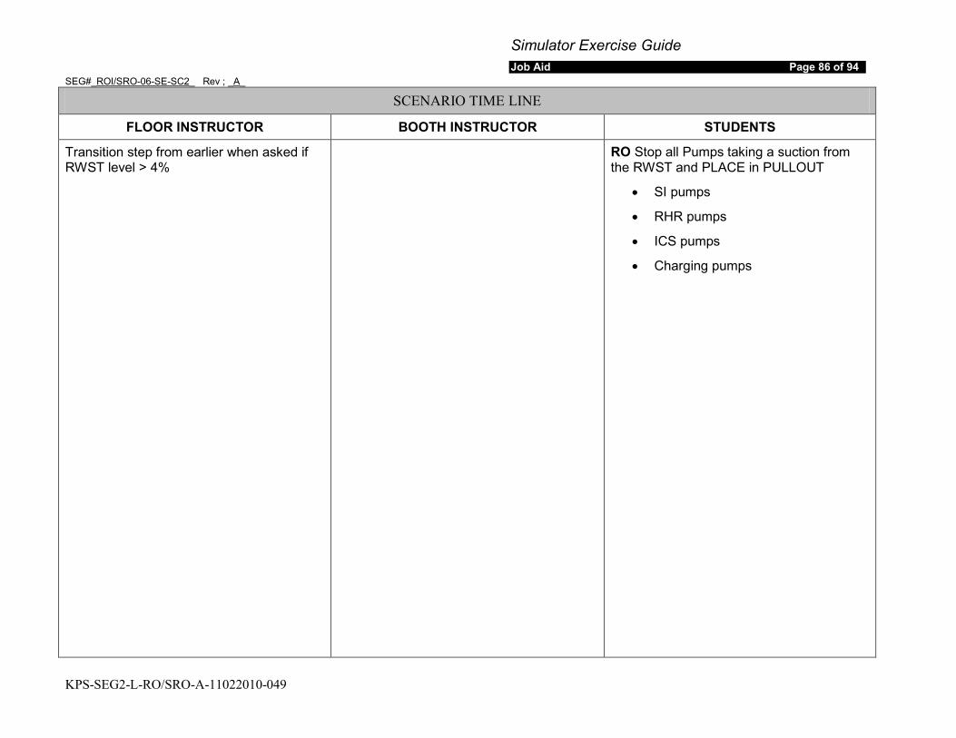
Simulator Exercise Guide Job Aid Page 86 of 94
SEG#_ROI/SRO-06-SE-SC2_ Rev ; _A_
KPS-SEG2-L-RO/SRO-A-11022010-049
SCENARIO TIME LINE
FLOOR INSTRUCTOR BOOTH INSTRUCTOR STUDENTS
Transition step from earlier when asked if RWST level > 4%
RO Stop all Pumps taking a suction from the RWST and PLACE in PULLOUT
• SI pumps
• RHR pumps
• ICS pumps
• Charging pumps
Simulator Exercise Guide Job Aid Page 87 of 94
SEG#_ROI/SRO-06-SE-SC2_ Rev ; _A_
KPS-SEG2-L-RO/SRO-A-11022010-049
SCENARIO TIME LINE
FLOOR INSTRUCTOR BOOTH INSTRUCTOR STUDENTS
6. SCENARIO END: a. FREEZE simulator at direction of floor instructor.
b. STOP DVD recorder. IF this is the last session of the week, THEN
c. STOP Data Capture via Monitor Files (optional)
FINALIZE the DVD (optional)
7. POST-SCENARIO:
a. ENSURE simulator problems encountered during the scenario are documented IAW site specific process.
b. ENSURE training attendance is documented on, Training Attendance Report.
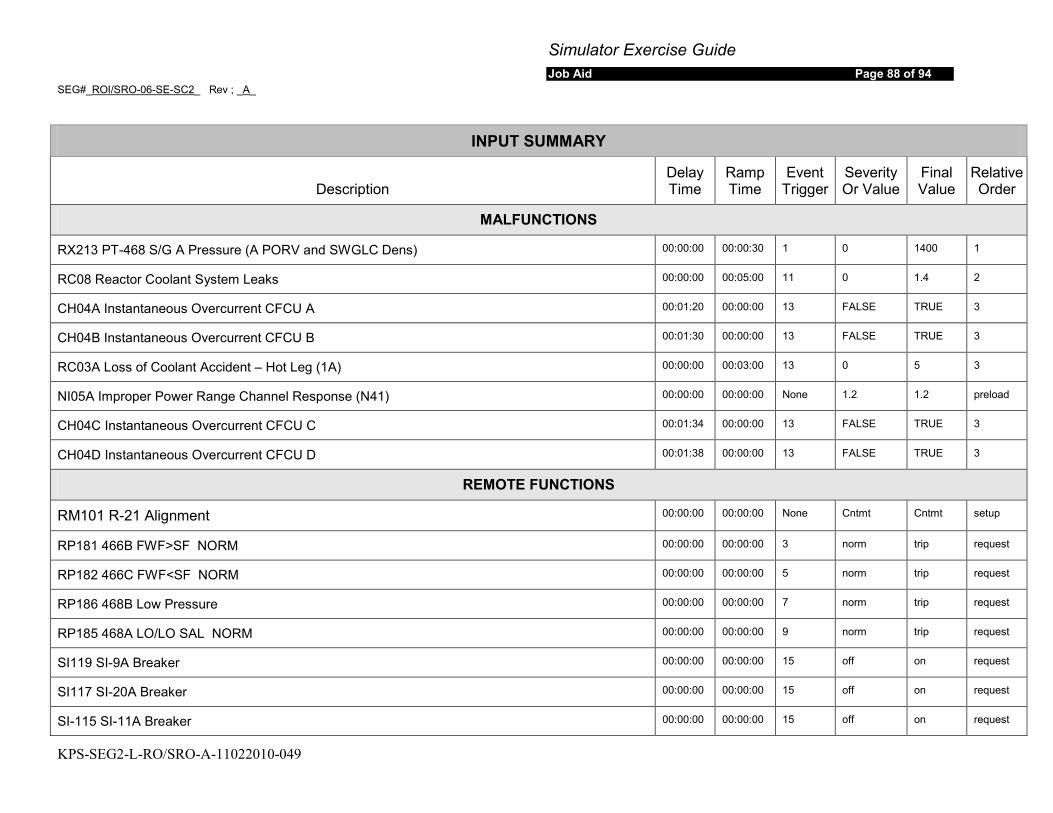
Simulator Exercise Guide Job Aid Page 88 of 94
SEG#_ROI/SRO-06-SE-SC2_ Rev ; _A_
KPS-SEG2-L-RO/SRO-A-11022010-049
INPUT SUMMARY
Description Delay Time
Ramp Time
Event Trigger
Severity Or Value
Final Value
Relative Order
MALFUNCTIONS
RX213 PT-468 S/G A Pressure (A PORV and SWGLC Dens) 00:00:00 00:00:30 1 0 1400 1
RC08 Reactor Coolant System Leaks 00:00:00 00:05:00 11 0 1.4 2
CH04A Instantaneous Overcurrent CFCU A 00:01:20 00:00:00 13 FALSE TRUE 3
CH04B Instantaneous Overcurrent CFCU B 00:01:30 00:00:00 13 FALSE TRUE 3
RC03A Loss of Coolant Accident – Hot Leg (1A) 00:00:00 00:03:00 13 0 5 3
NI05A Improper Power Range Channel Response (N41) 00:00:00 00:00:00 None 1.2 1.2 preload
CH04C Instantaneous Overcurrent CFCU C 00:01:34 00:00:00 13 FALSE TRUE 3
CH04D Instantaneous Overcurrent CFCU D 00:01:38 00:00:00 13 FALSE TRUE 3
REMOTE FUNCTIONS
RM101 R-21 Alignment 00:00:00 00:00:00 None Cntmt Cntmt setup
RP181 466B FWF>SF NORM 00:00:00 00:00:00 3 norm trip request
RP182 466C FWF<SF NORM 00:00:00 00:00:00 5 norm trip request
RP186 468B Low Pressure 00:00:00 00:00:00 7 norm trip request
RP185 468A LO/LO SAL NORM 00:00:00 00:00:00 9 norm trip request
SI119 SI-9A Breaker 00:00:00 00:00:00 15 off on request
SI117 SI-20A Breaker 00:00:00 00:00:00 15 off on request
SI-115 SI-11A Breaker 00:00:00 00:00:00 15 off on request
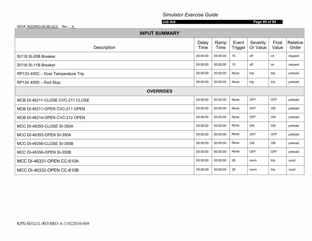
Simulator Exercise Guide Job Aid Page 89 of 94
SEG#_ROI/SRO-06-SE-SC2_ Rev ; _A_
KPS-SEG2-L-RO/SRO-A-11022010-049
INPUT SUMMARY
Description Delay Time
Ramp Time
Event Trigger
Severity Or Value
Final Value
Relative Order
SI118 SI-20B Breaker 00:00:00 00:00:00 15 off on request
SI116 SI-11B Breaker 00:00:00 00:00:00 15 off on request
RP133 405C – Over Temperature Trip 00:00:00 00:00:00 None trip trip preload
RP134 405D – Rod Stop 00:00:00 00:00:00 None trip trip preload
OVERRIDES
MCB DI-46211-CLOSE CVC-211 CLOSE 00:00:00 00:00:00 None OFF OFF preload
MCB DI-46211-OPEN CVC-211 OPEN 00:00:00 00:00:00 None OFF ON preload
MCB DI-46214-OPEN CVC-212 OPEN 00:00:00 00:00:00 None OFF ON preload
MCC DI-46355-CLOSE SI-350A 00:00:00 00:00:00 None ON ON preload
MCC DI-46355-OPEN SI-350A 00:00:00 00:00:00 None OFF OFF preload
MCC DI-46356-CLOSE SI-350B 00:00:00 00:00:00 None ON ON preload
MCC DI-46356-OPEN SI-350B 00:00:00 00:00:00 None OFF OFF preload
MCC DI-46331-OPEN CC-610A 00:00:00 00:00:00 28 norm trip cond
MCC DI-46332-OPEN CC-610B 00:00:00 00:00:00 28 norm trip cond
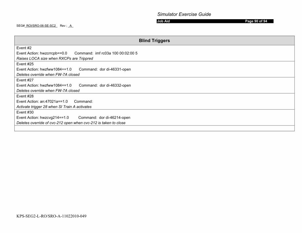
Simulator Exercise Guide Job Aid Page 90 of 94
SEG#_ROI/SRO-06-SE-SC2_ Rev ; _A_
KPS-SEG2-L-RO/SRO-A-11022010-049
Blind Triggers Event #2 Event Action: hwzcrrcpb==0.0 Command: imf rc03a 100 00:02:00 5 Raises LOCA size when RXCPs are Trippred Event #25 Event Action: hwzfww1084==1.0 Command: dor di-46331-open Deletes override when FW-7A closed Event #27 Event Action: hwzfww1084==1.0 Command: dor di-46332-open Deletes override when FW-7A closed Event #28 Event Action: an:47021a==1.0 Command: Activate trigger 28 when SI Train A activates Event #30 Event Action: hwzcvg214==1.0 Command: dor di-46214-open Deletes override of cvc-212 open when cvc-212 is taken to close

Simulator Exercise Guide Job Aid Page 91 of 94
SEG#_ROI/SRO-06-SE-SC2_ Rev ; _A_
KPS-SEG2-L-RO/SRO-A-11022010-049
SIMULATOR SCENARIO DEVELOPMENT CHECKLIST
Mark with an “X” Yes or No for any of the following. If the answer is No, include an explanation after the item.
Yes No
1. The scenario contains objectives for the desired tasks and relevant Human Performance Tools.
2. The scenario content adequately addresses the desired tasks, through simulator performance, instructor-led training freezes, or both.
3. Plant PRA initiating events, important equipment, and important tasks are identified.
4. Turnover information includes a Daily At Power Risk Assessment provided by the PRA Group. – Done by the Crew during validation
5. The scenario contains procedurally driven success paths. Procedural discrepancies are identified and corrected before training is given.
6. The Scenario Guide includes responses for all communications to simulated personnel outside the Control Room, based on procedural guidance and standard operating practices.
7. The scenario includes related industry experience. Not Required for Evaluations
8. Training elements and specific Human Performance elements are addressed in the Scenario Critique Guide to be used by the Critique Facilitator. The Critique Guide includes standards for expected performance.
9. Any identified Critical Tasks possesses the following elements (NUREG-1021): • Essential to safety with adverse consequences or significant degradation, • Cue(s) prompt the Operator to respond. • Defined and measurable performance indicators. • Performance feedback.
The use of “N/A” is allowed for item 9 only if this is NOT
an evaluated scenario.
10. Technical Specifications including Limiting Conditions for Operation, reactivity briefings, and Emergency-Plan entries are addressed as appropriate.
Developer and Reviewer: Once checklist is completed and deficiencies are corrected, sign the cover page.
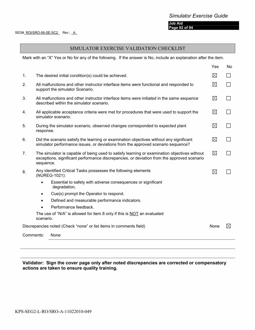
Simulator Exercise Guide Job Aid Page 92 of 94
SEG#_ROI/SRO-06-SE-SC2_ Rev ; _A_
KPS-SEG2-L-RO/SRO-A-11022010-049
SIMULATOR EXERCISE VALIDATION CHECKLIST
Mark with an “X” Yes or No for any of the following. If the answer is No, include an explanation after the item.
Yes No
1. The desired initial condition(s) could be achieved.
2. All malfunctions and other instructor interface items were functional and responded to support the simulator Scenario.
3. All malfunctions and other instructor interface items were initiated in the same sequence described within the simulator scenario.
4. All applicable acceptance criteria were met for procedures that were used to support the simulator scenario.
5. During the simulator scenario, observed changes corresponded to expected plant response.
6. Did the scenario satisfy the learning or examination objectives without any significant simulator performance issues, or deviations from the approved scenario sequence?
7. The simulator is capable of being used to satisfy learning or examination objectives without exceptions, significant performance discrepancies, or deviation from the approved scenario sequence.
8. Any identified Critical Tasks possesses the following elements (NUREG-1021):
• Essential to safety with adverse consequences or significant degradation,
• Cue(s) prompt the Operator to respond. • Defined and measurable performance indicators. • Performance feedback.
The use of “N/A” is allowed for item 8 only if this is NOT
an evaluated scenario.
Discrepancies noted (Check “none” or list items in comments field) None
Comments: None
Validator: Sign the cover page only after noted discrepancies are corrected or compensatory actions are taken to ensure quality training.
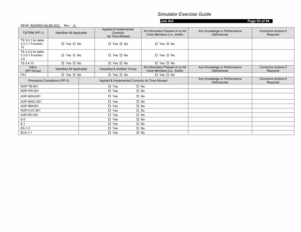
Simulator Exercise Guide Job Aid Page 93 of 94
SEG#_ROI/SRO-06-SE-SC2_ Rev ; _A_
TS/TRM (PP-1) Identified All Applicable Applied & Implemented
Correctly As Time Allowed
All Information Passed on to All Crew Members (i.e., briefs)
Any Knowledge or Performance Deficiencies
Corrective Actions if Required
TS 3.3.1 for table 3.3.1-1 Function 15
Yes No Yes No Yes No
TS 3.3.2 for table 3.3.2-1 Function 1,e
Yes No Yes No Yes No
TS 3.4.13 Yes No Yes No Yes No EALs
(EP Group) Identified All Applicable Classified & Notified Timely All Information Passed on to All Crew Members (i.e., briefs)
Any Knowledge or Performance Deficiencies
Corrective Actions if Required
FA1 Yes No Yes No Yes No
Procedure Compliance (PP-3) Applied & Implemented Correctly As Time Allowed Any Knowledge or Performance Deficiencies
Corrective Actions if Required
NOP-TB-001 Yes No NOP-FW-001 Yes No
AOP-GEN-001 Yes No
AOP-MISC-001 Yes No AOP-RM-001 Yes No NOP-CVC-001 Yes No AOP-RC-001 Yes No E-0 Yes No E-1 Yes No ES-1.3 Yes No ECA-1.1 Yes No
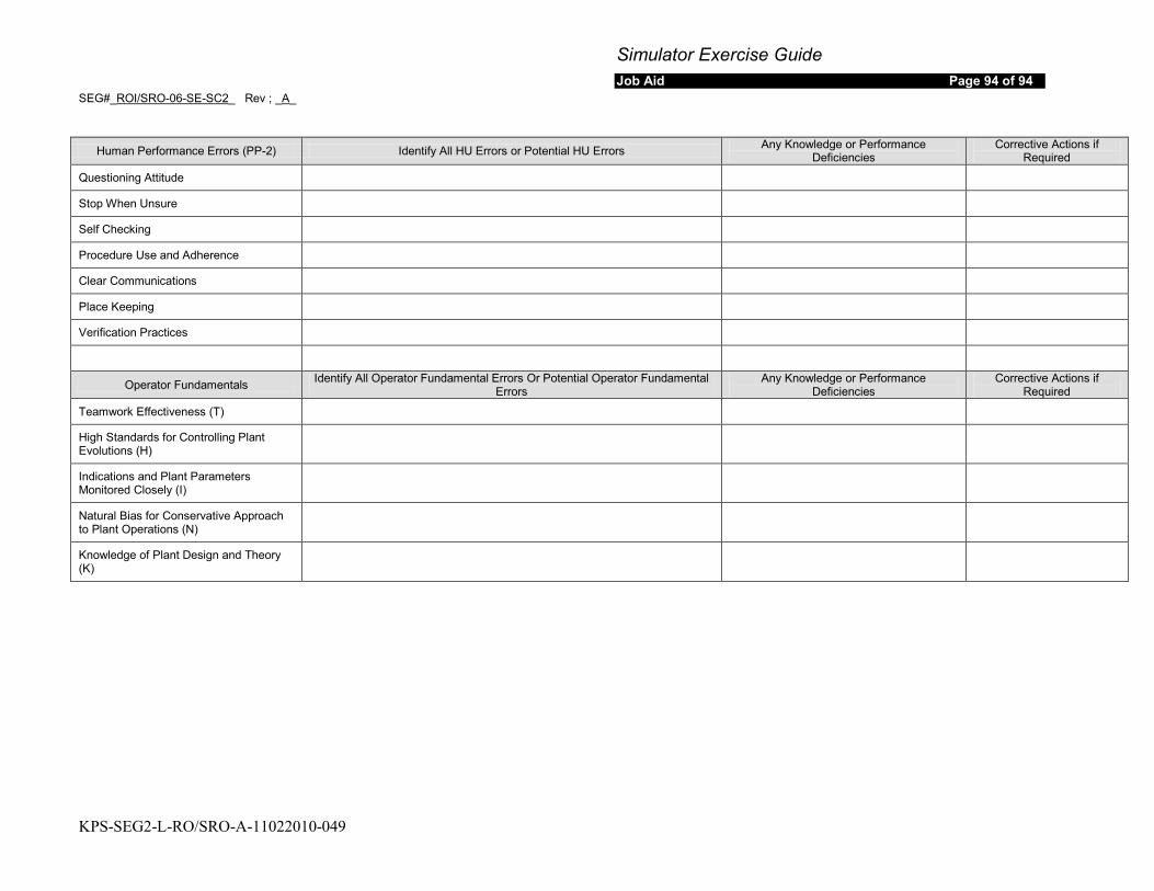
Simulator Exercise Guide Job Aid Page 94 of 94
SEG#_ROI/SRO-06-SE-SC2_ Rev ; _A_
KPS-SEG2-L-RO/SRO-A-11022010-049
Human Performance Errors (PP-2) Identify All HU Errors or Potential HU Errors Any Knowledge or Performance
Deficiencies Corrective Actions if
Required
Questioning Attitude
Stop When Unsure
Self Checking
Procedure Use and Adherence
Clear Communications
Place Keeping
Verification Practices
Operator Fundamentals Identify All Operator Fundamental Errors Or Potential Operator Fundamental Errors
Any Knowledge or Performance Deficiencies
Corrective Actions if Required
Teamwork Effectiveness (T)
High Standards for Controlling Plant Evolutions (H)
Indications and Plant Parameters Monitored Closely (I)
Natural Bias for Conservative Approach to Plant Operations (N)
Knowledge of Plant Design and Theory (K)

Simulator Exercise Guide Job Aid Page 1 of 52
SEG# ROI/SOI-06-SE-SC3 Rev: A
KPS-SEG3-L-RO/SRO-A-11022010-051
SITE: Kewaunee Power Station
PROGRAM: RO/SRO License Training
PROGRAM No. ROI/SRO-TP
COURSE: 2011 NRC License Exam Course #: ROI-06-SE-SC3 SOI-06-SE-SC3
Total Time 1.5 hours
Prepared by: Andrew Fahrenkrug /s 11/01/2010 Printed Name Instructor’s Signature Date
Reviewed by: Jeffrey A. Hinze /s 11/03/2010 (Optional) Printed Name Simulator Development Checklist
Instructor Signature Date
Reviewed by: Andrew Fahrenkrug /s 09/16/2010 (Optional) Printed Name Simulator Validation Checklist
Signature Date
Approved by: Randy Hasting /s 11/10/2010 Printed Name Training Supervisor Date
Approved by: Mark Gooslbey /s 11/11/2010 Printed Name Facility Representative Date

Simulator Exercise Guide SEG# ROI/SOI-06-SE-SC3 Rev: A
KPS-SEG3-L-RO/SRO-A-11022010-051
Job Aid Page 2 of 52
REQUIREMENTS
Goal of Training: Evaluate crew response and performance for the following events: • SG Tube Leak occurs in SG B • Rapid Power reduction required by the SG Tube Leak • During the power reduction, Emergency Boration path will function
properly, the normal path will be used. • A steam line leak from the ‘B’ steam header outside of containment.
Learning Objectives: While responding as the RO/BOP satisfactorily MEET the performance requirements in TR-AA-400 for the following competencies
a. Understand and Interpret Annunciator and Alarm Signals b. Diagnose Events and Conditions based on Signals and Reading c. Understand Plant and System Response d. Comply with and Use Procedures and Technical Specifications e. Operate the Control Board f. Communicate and Interact with Other Crew Members
(RO4-06-SED01.002) ROI-06-SE-SC03.001 / SOI-06-SE-SC03.001 While responding as the US satisfactorily MEET the performance requirements in TR-AA-400 for the following competencies
a. Understand and Interpret Annunciator and Alarm Signals b. Diagnose Events and Conditions based on Signals and Reading c. Understand Plant and System Response d. Comply with and Use Procedures and Technical Specifications e. Operate the Control Board f. Communicate and Interact with Other Crew Members g. Direct Shift Operations h. Comply with and Use Technical Specifications
(RO4-06-SED01.003) SOI-06-SE-SC03.002
As the US DETERMINE the appropriate event classification in accordance with EPIP-AD-02,”Emegency Classification Determination”. (This objective will be completed at the end of the scenario and may be waived at the lead evaluator’s discretion.) SOI-06-SE-SC03.003
Prerequisites: Enrolled in current ILT class and recommended by station management to take an NRC license exam.
Training Resources: Simulator KPS Exam Team Member NRC Examiners
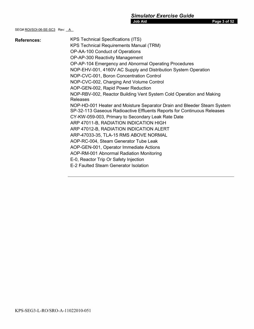
Simulator Exercise Guide SEG# ROI/SOI-06-SE-SC3 Rev: A
KPS-SEG3-L-RO/SRO-A-11022010-051
Job Aid Page 3 of 52
References: KPS Technical Specifications (ITS) KPS Technical Requirements Manual (TRM) OP-AA-100 Conduct of Operations OP-AP-300 Reactivity Management OP-AP-104 Emergency and Abnormal Operating Procedures NOP-EHV-001, 4160V AC Supply and Distribution System Operation NOP-CVC-001, Boron Concentration Control NOP-CVC-002, Charging And Volume Control AOP-GEN-002, Rapid Power Reduction NOP-RBV-002, Reactor Building Vent System Cold Operation and Making Releases NOP-HD-001 Heater and Moisture Separator Drain and Bleeder Steam System SP-32-113 Gaseous Radioactive Effluents Reports for Continuous Releases CY-KW-059-003, Primary to Secondary Leak Rate Date ARP 47011-B, RADIATION INDICATION HIGH ARP 47012-B, RADIATION INDICATION ALERT ARP-47033-35, TLA-15 RMS ABOVE NORMAL AOP-RC-004, Steam Generator Tube Leak AOP-GEN-001, Operator Immediate Actions AOP-RM-001 Abnormal Radiation Monitoring E-0, Reactor Trip Or Safety Injection E-2 Faulted Steam Generator Isolation

Simulator Exercise Guide SEG# ROI/SOI-06-SE-SC3 Rev: A
KPS-SEG3-L-RO/SRO-A-11022010-051
Job Aid Page 4 of 52
Commitments: Per Outline submitted to NRC for 2011 Operating exam
Evaluation Method: Dynamic Simulator
Historical Record: Initial Issue
Operating Experience: Not required for evaluations
Related PRA Information:
Initiating Event with Core Damage Frequency:Total CDF/LERF (3.6E-5/yr)/(1.6E-06/yr)
Transient with MFW Available CDF/LERF 10%/2.8% High Energy Line Break CDF/LERF 6%/2.2% Important Components
System
:
CDF Importance Rank LERF Importance Rank
AFW 3rd 2 nd
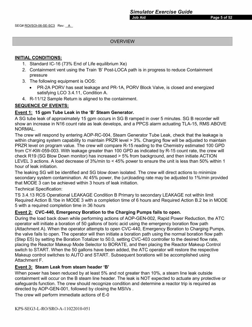
Simulator Exercise Guide SEG# ROI/SOI-06-SE-SC3 Rev: A
KPS-SEG3-L-RO/SRO-A-11022010-051
Job Aid Page 5 of 52
OVERVIEW
1. Standard IC-16 (73% End of Life equilibrium Xe) INITIAL CONDITIONS:
2. Containment vent using the Train ‘B’ Post-LOCA path is in progress to reduce Containment pressure
3. The following equipment is OOS: • PR-2A PORV has seat leakage and PR-1A, PORV Block Valve, is closed and energized
satisfying LCO 3.4.11, Condition A. 4. R-11/12 Sample Return is aligned to the containment.
SEQUENCE OF EVENTS: Event 1:A SG tube leak of approximately 15 gpm occurs in SG B ramped in over 5 minutes. SG B recorder will show an increase in N16 count rate as leak develops, and a PPCS alarm actuating TLA-15, RMS ABOVE NORMAL.
15 gpm Tube Leak in the ‘B’ Steam Generator.
The crew will respond by entering AOP-RC-004, Steam Generator Tube Leak, check that the leakage is within charging system capability to maintain PRZR level > 3%. Charging flow will be adjusted to maintain PRZR level on program value. The crew will compare R-15 reading to the Chemistry estimated 100 GPD from CY-KW-059-003. With leakage greater than 100 GPD as indicated by R-15 count rate, the crew will check R19 (SG Blow Down monitor) has increased > 5% from background, and then initiate ACTION LEVEL 3 actions. A load decrease of 3%/min to < 45% power to ensure the unit is less than 50% within 1 hour of leak initiation. The leaking SG will be identified and SG blow down isolated. The crew will direct actions to minimize secondary system contamination. At 45% power, the (un)loading rate may be adjusted to 1%/min provided that MODE 3 can be achieved within 3 hours of leak initiation. Technical Specification: TS 3.4.13 RCS Operational LEAKAGE Condition B Primary to secondary LEAKAGE not within limit Required Action B.1be in MODE 3 with a completion time of 6 hours and Required Action B.2 be in MODE 5 with a required completion time in 36 hours Event 2:During the load back down while performing actions of AOP-GEN-002, Rapid Power Reduction, the ATC operator will initiate a boration of 50 gallons of boric acid using the emergency boration flow path (Attachment A). When the operator attempts to open CVC-440, Emergency Boration to Charging Pumps, the valve fails to open. The operator will then initiate a boration path using the normal boration flow path (Step E5) by setting the Boration Totalizer to 50.0, setting CVC-403 controller to the desired flow rate, placing the Reactor Makeup Mode Selector to BORATE, and then placing the Reactor Makeup Control switch to START. When the 50 gallons have been added, the ATC operator will restore the respective Makeup control switches to AUTO and START. Subsequent borations will be accomplished using Attachment F.
CVC-440, Emergency Boration to the Charging Pumps fails to open.
Event 3:When power has been reduced by at least 5% and not greater than 10%, a steam line leak outside containment will occur on the B steam line header. The leak is NOT expected to actuate any protective or safeguards function. The crew should recognize condition and determine a reactor trip is required as directed by AOP-GEN-001, followed by closing the MSIVs .
Steam Leak from steam header ‘B’
The crew will perform immediate actions of E-0
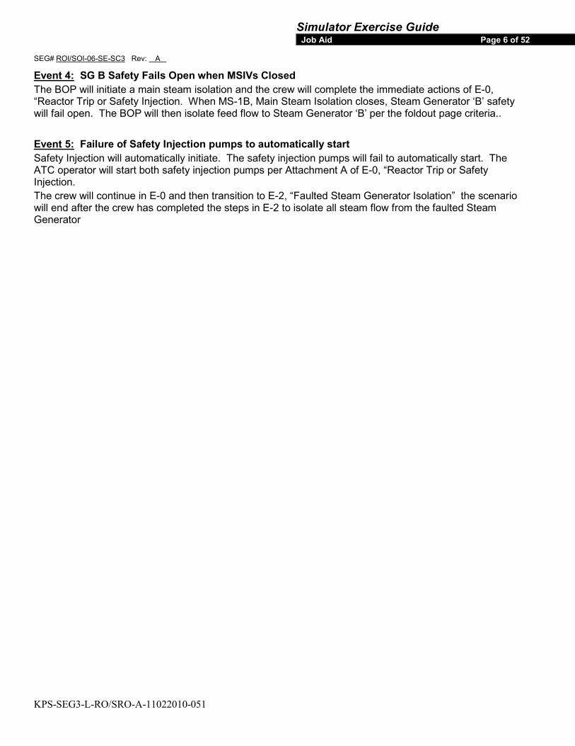
Simulator Exercise Guide SEG# ROI/SOI-06-SE-SC3 Rev: A
KPS-SEG3-L-RO/SRO-A-11022010-051
Job Aid Page 6 of 52
Event 4:The BOP will initiate a main steam isolation and the crew will complete the immediate actions of E-0, “Reactor Trip or Safety Injection. When MS-1B, Main Steam Isolation closes, Steam Generator ‘B’ safety will fail open. The BOP will then isolate feed flow to Steam Generator ‘B’ per the foldout page criteria..
SG B Safety Fails Open when MSIVs Closed
Event 5:Safety Injection will automatically initiate. The safety injection pumps will fail to automatically start. The ATC operator will start both safety injection pumps per Attachment A of E-0, “Reactor Trip or Safety Injection.
Failure of Safety Injection pumps to automatically start
The crew will continue in E-0 and then transition to E-2, “Faulted Steam Generator Isolation” the scenario will end after the crew has completed the steps in E-2 to isolate all steam flow from the faulted Steam Generator
Simulator Exercise Guide SEG# ROI/SOI-06-SE-SC3 Rev: A
KPS-SEG3-L-RO/SRO-A-11022010-051
Job Aid Page 7 of 52
Before EOP Entry: Malfunctions:
1. Steam Generator Tube Leak 2. CVC-440 Emergency Boration to the Charging Pumps fails closed 3. Steam Line Leak, ‘B’ Steam Header
After EOP Entry: 1. SG B Safety Fails Open 2. SI Pumps fail to auto start
1. Steam Generator Tube Leak Abnormal Events:
2. Steam Leak Out side Containment
1. SG B Safety fails open during main steam isolation resulting in Safety Injection Major Transients:
Critical Tasks
CRITICAL TASK: Isolate feed flow to faulted Steam Generator B by the completion of the Step in E-2 requiring isolation of feed flow
a) SAFETY SIGNIFICANCE: i) Failure to isolate feed flow to the faulted steam generator that can be isolated causes a challenge
to CSFs beyond those irreparably introduced by the scenario conditions b) CUE:
i) Steam Flow indicated on B Steam Header with MS-1B closed, Steam Generator ‘B’ pressure lowering in an uncontrolled manner.
c) MEASURABLE PERFORMANCE INDICATOR: i) AFW-2B closed and AFW-10B or AFW-10A closed by completion of Step 4 of E-2
d) PERFORMANCE FEEDBACK: i) No feed water flow indicated on AFW Header B
Simulator Exercise Guide SEG# ROI/SOI-06-SE-SC3 Rev: A
KPS-SEG3-L-RO/SRO-A-11022010-051
Job Aid Page 8 of 52
TASKS
Task Number Task Title
SRO Tasks:
1190190302 Apply Technical Specifications During Plant Operations
1190070502 Coordinate the Implementation of the IPEOPs
1190330302 Demonstrate an understanding of the responsibility and requirements for the Control Room Supervisor
A030010402 Perform a Rapid Power Reduction
RO Tasks:
0540060101 Change Turbine and Generator Load
0350240101 Control RCS Boron Concentration by the use of Boration
1190250301 Respond to a Steam Generator Tube Leak
E000010501 Respond to a Reactor Trip Condition with Safety Injection
A030010402 Perform a Rapid Power Reduction
STA Tasks: N/A

Simulator Exercise Guide SEG# ROI/SOI-06-SE-SC3 Rev: A
KPS-SEG3-L-RO/SRO-A-11022010-051
Job Aid Page 9 of 52
SCENARIO TIME LINE
FLOOR INSTRUCTOR BOOTH INSTRUCTOR STUDENTS
1. INITIAL CONDITIONS: • Standard IC 16 • Mode: 1 • Exposure: 17000 • Power: 75.3% • Boron: (CB): 162 ppm • Temperature: 564.8ºF • Pressure: 2235 psig • Xenon: Equil • Rods: D170 • Generator: 452 Mwe • Thermal Power 1347.5 Mwth
Simulator Exercise Guide SEG# ROI/SOI-06-SE-SC3 Rev: A
KPS-SEG3-L-RO/SRO-A-11022010-051
Job Aid Page 10 of 52
SCENARIO TIME LINE
FLOOR INSTRUCTOR BOOTH INSTRUCTOR STUDENTS
2. SIMULATOR SETUP: The following forms are needed during the scenario and are to be placed in the booth. No Additional Material Need For Booth
Operator
Shift Manager Status board information
PR-2A excessive seat leakage Equipment OOS
TS 3.4.11 (Reactor Coolant System Pressurizer Power Operated Relief Valves) Condition A One or more PORVs inoperable and capable of being manually cycled. Required Action A.1 is to close and maintain power to the associated PORV Block Valve with a completion time of one hour (Completed).
• RESET to IC# 16 and go to run • Align R-21 to containment using remote
RM101 • POSITION AS-31/AS-35, R-11 and R-12
Sample return to return to the containment. • ALIGN Containment Vent 2” path:
• PLACE Containment Dome Fan B to START
• STOP Containment Dome Fan A and PLACE in AUTO
• OPEN LOCA-2B, Post-LOCA Hydrogen Cntmt Vent Isol B
• OPEN LOCA-100B, Post-LOCA Hydrogen To Recombiner B
• PLACE PR-1A to CLOSE, and PLACE clearance status tag
• OPEN and Run CAEP file. ROI-06-SE-SC4-preload.cae. After file has run for one minute
• Verify the Instructor Station Summary IAW instructions at the beginning of the input summary in this SEG
close CAE file.
• Second verification of the Instructor IAW instructions at the beginning of the input summary in this SEG
• Start the Monitor File using the NRC Extended Value Monitor File.
• ENSURE Job Aid 04-009, Simulator Exam/EP Drill Setup and Cleanup adequate to support exam by COMPLETING ATTACHMENT 1, Simulator Setup Exams/EP Drill, or ATTACHMENT 2, Reset Exam/EP Drill, as appropriate
Simulator Exercise Guide SEG# ROI/SOI-06-SE-SC3 Rev: A
KPS-SEG3-L-RO/SRO-A-11022010-051
Job Aid Page 11 of 52
SCENARIO TIME LINE
FLOOR INSTRUCTOR BOOTH INSTRUCTOR STUDENTS
Protected train = A Remarks
Risk CDF/LERF= Green
None SPER / WRs
Consecutive days of operation ___GENERAL
490G-1 Closed
____ (indicate date last month) JD
Burn up
xxx
Sirens Lost Coverage % 17,000 MWD/MTU
Sirens OOS __0__
RCS and Pressurizer boron = 162 ppm __0__
All other entries are standard
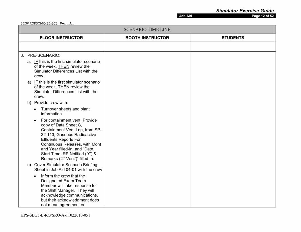
Simulator Exercise Guide SEG# ROI/SOI-06-SE-SC3 Rev: A
KPS-SEG3-L-RO/SRO-A-11022010-051
Job Aid Page 12 of 52
SCENARIO TIME LINE
FLOOR INSTRUCTOR BOOTH INSTRUCTOR STUDENTS 3. PRE-SCENARIO:
a. IF this is the first simulator scenario of the week, THEN
a)
review the Simulator Differences List with the crew. IF this is the first simulator scenario of the week, THEN
b) Provide crew with:
review the Simulator Differences List with the crew.
• Turnover sheets and plant information
• For containment vent, Provide copy of Data Sheet C, Containment Vent Log, from SP-32-113, Gaseous Radioactive Effluents Reports For Continuous Releases, with Mont and Year filled-in, and “Date, Start Time, RP Notified (‘Y’) & Remarks (‘2” Vent’)” filled-in.
c) Cover Simulator Scenario Briefing Sheet in Job Aid 04-01 with the crew • Inform the crew that the
Designated Exam Team Member will take response for the Shift Manager. They will acknowledge communications, but their acknowledgment does not mean agreement or

Simulator Exercise Guide SEG# ROI/SOI-06-SE-SC3 Rev: A
KPS-SEG3-L-RO/SRO-A-11022010-051
Job Aid Page 13 of 52
SCENARIO TIME LINE
FLOOR INSTRUCTOR BOOTH INSTRUCTOR STUDENTS disagreement.
d) ENSURE the crew has been briefed IAW NUREG 1021 Appendix E (Simulator Test Guidelines)
e) If allowed by the NRC Chief Examiner, Lead Exam Team Member will perform a Pre-Job brief per Job Aid 04-03.
4. TURNOVER: PROVIDE Shift Turnover Information.
After ~5 minute walk down of boards by the crew. Give the crew the shift.
Maintain current power until direction given by management to raise power
Shift Direction:
If permission has been given by the NRC Chief Examiner then when Crew enters the simulator than begin recording on the DVD.
(All) Walk down control boards~ 5 minutes
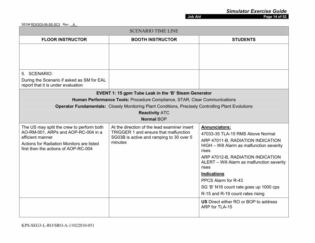
Simulator Exercise Guide SEG# ROI/SOI-06-SE-SC3 Rev: A
KPS-SEG3-L-RO/SRO-A-11022010-051
Job Aid Page 14 of 52
SCENARIO TIME LINE
FLOOR INSTRUCTOR BOOTH INSTRUCTOR STUDENTS
5. SCENARIO: During the Scenario if asked as SM for EAL report that it is under evaluation
EVENT 1: 15 gpm Tube Leak in the ‘B’ Steam Generator Human Performance Tools: Procedure Compliance, STAR, Clear Communications
Operator Fundamentals: Closely Monitoring Plant Conditions, Precisely Controlling Plant Evolutions Reactivity ATC
Normal BOP
The US may split the crew to perform both AO-RM-001, ARPs and AOP-RC-004 in a efficient manner Actions for Radiation Monitors are listed first then the actions of AOP-RC-004
At the direction of the lead examiner insert TRIGGER 1 and ensure that malfunction SG03B is active and ramping to 30 over 5 minutes
47033-35 TLA-15 RMS Above Normal Annunciators:
ARP 47011-B, RADIATION INDICATION HIGH – Will Alarm as malfunction severity rises ARP 47012-B, RADIATION INDICATION ALERT – Will Alarm as malfunction severity rises
PPCS Alarm for R-43 Indications
SG ‘B’ N16 count rate goes up 1000 cps R-15 and R-19 count rates rising
US Direct either RO or BOP to address ARP for TLA-15

Simulator Exercise Guide SEG# ROI/SOI-06-SE-SC3 Rev: A
KPS-SEG3-L-RO/SRO-A-11022010-051
Job Aid Page 15 of 52
SCENARIO TIME LINE
FLOOR INSTRUCTOR BOOTH INSTRUCTOR STUDENTS
ARP-47033-35 TLA-15 RMS Above Normal ROLE: SM REQUEST: Inform RP of Rad Monitor Alarms and to survey the affected areas. RESPONSE: Acknowledge request to contact RP and after delay report that RP has been informed DELAY: One Minute
ROLE: RP REQUEST: Inform of Rad Monitor Alarms and to survey the affected areas. RESPONSE: Acknowledge the Rad Monitor Alarms & Surveys. And any other request made by the crew. DELAY: None
BOP/RO Check alarm due to any of the following:
• R-15 • R-19 • R-42 • R-43
Direct RP to Survey the affected area
US Transition to AOP-RC-004
ARP- 47012-B Radiation Indication Alert ROLE: SM REQUEST: Inform RP of Rad Monitor Alarms and to survey the affected areas. RESPONSE: Acknowledge request to contact RP and after delay report that RP has been informed DELAY: One Minute
ROLE: RP REQUEST: Inform of Rad Monitor Alarms and to survey the affected areas. RESPONSE: Acknowledge the Rad Monitor Alarms & Surveys. And any other request made by the crew. DELAY: None
RO/BOP Check if Alert alarm expected due to a planned evolution RNO Perform the following
• Determine channel in Alert • Notify Radiation Protection to assist
in identifying and isolating source
US Transition to AOP-RM-001
ARP- 47011-B Radiation Indication High ROLE: SM REQUEST: Inform RP of Rad Monitor Alarms and to survey the affected areas.
ROLE: RP REQUEST: Inform of Rad Monitor Alarms and to survey the affected areas.
RO/BOP Check if High alarm expected due to a planned evolution RNO
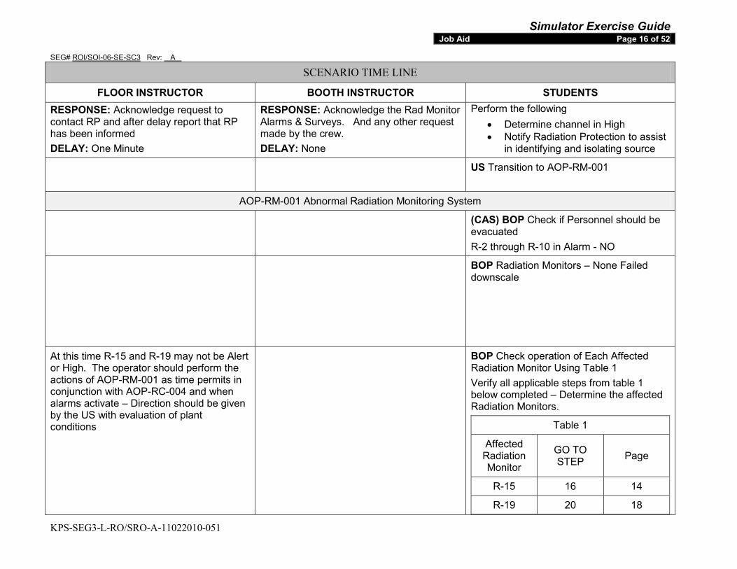
Simulator Exercise Guide SEG# ROI/SOI-06-SE-SC3 Rev: A
KPS-SEG3-L-RO/SRO-A-11022010-051
Job Aid Page 16 of 52
SCENARIO TIME LINE
FLOOR INSTRUCTOR BOOTH INSTRUCTOR STUDENTS RESPONSE: Acknowledge request to contact RP and after delay report that RP has been informed DELAY: One Minute
RESPONSE: Acknowledge the Rad Monitor Alarms & Surveys. And any other request made by the crew. DELAY: None
Perform the following • Determine channel in High • Notify Radiation Protection to assist
in identifying and isolating source
US Transition to AOP-RM-001
AOP-RM-001 Abnormal Radiation Monitoring System
(CAS) BOP Check if Personnel should be evacuated R-2 through R-10 in Alarm - NO
BOP Radiation Monitors – None Failed downscale
At this time R-15 and R-19 may not be Alert or High. The operator should perform the actions of AOP-RM-001 as time permits in conjunction with AOP-RC-004 and when alarms activate – Direction should be given by the US with evaluation of plant conditions
BOP Check operation of Each Affected Radiation Monitor Using Table 1 Verify all applicable steps from table 1 below completed – Determine the affected Radiation Monitors.
Table 1
Affected Radiation Monitor
GO TO STEP Page
R-15 16 14
R-19 20 18

Simulator Exercise Guide SEG# ROI/SOI-06-SE-SC3 Rev: A
KPS-SEG3-L-RO/SRO-A-11022010-051
Job Aid Page 17 of 52
SCENARIO TIME LINE
FLOOR INSTRUCTOR BOOTH INSTRUCTOR STUDENTS
R-43 32 27
AOP-RM-001 for R-15 Alarming
BOP/RO Check R-15 Operating properly
Expected that the US will be continuing with AOP-RC-004 with the operator not performing AOP-RM-001 or wait until back down is started until addressing all the actions in AOP-RM-001
ROLE: EO REQUEST: Inform of Alarm and direct to close HS-17 RESPONSE: Acknowledge the information given and direction to close HS-17. After Delay report that HS-17 closed DELAY: 4 minutes
BOP/RO Check R-15 Radiation Levels Normal RNO Perform the following If High Radiation alarm has occurred then perform the following:
• Check the specific automatic actions of Attachment A have occurred
o AR-6 Positioned to Duct o BT-2A Closed o BT-2B Closed o BT-3A Closed o BT-3B Closed o BT-31A Closed o BT-31B Closed o BT-32A Closed o BT-32B Closed o HS-17-1Closed
• CLOSE Stm Supply to AHU-1 Humidifier
o HS-17

Simulator Exercise Guide SEG# ROI/SOI-06-SE-SC3 Rev: A
KPS-SEG3-L-RO/SRO-A-11022010-051
Job Aid Page 18 of 52
SCENARIO TIME LINE
FLOOR INSTRUCTOR BOOTH INSTRUCTOR STUDENTS • If radiation indication in Alert or High
alarm range then perform AOP-RC-004 while continuing with this procedure
• When the Alarm Clears – Not expected to clear during the scenario
AOP-RM-001 for R-19 Alarming
BOP/RO Check R-19 Operating properly
Expected that the US will be continuing with AOP-RC-004 with the operator not performing AOP-RM-001 or wait until back down is started until addressing all the actions in AOP-RM-001
ROLE: EO REQUEST: Inform of Alarm and direct to close HS-17 RESPONSE: Acknowledge the information given and direction to close HS-17. After Delay report that HS-17 closed DELAY: 4 minutes
BOP/RO Check R-19 Radiation Levels Normal RNO Perform the following If High Radiation alarm has occurred then perform the following:
• Check the specific automatic actions of Attachment A have occurred
o AR-6 Positioned to Duct o BT-2A Closed o BT-2B Closed o BT-3A Closed o BT-3B Closed o BT-31A Closed o BT-31B Closed o BT-32A Closed o BT-32B Closed o HS-17-1Closed
• CLOSE Stm Supply to AHU-1 Humidifier

Simulator Exercise Guide SEG# ROI/SOI-06-SE-SC3 Rev: A
KPS-SEG3-L-RO/SRO-A-11022010-051
Job Aid Page 19 of 52
SCENARIO TIME LINE
FLOOR INSTRUCTOR BOOTH INSTRUCTOR STUDENTS o HS-17
• If radiation indication in Alert or High alarm range then perform AOP-RC-004 while continuing with this procedure
• When the Alarm Clears – Not expected to clear during the scenario
AOP-RM-001 for R-43 Alarming
BOP/RO Check R-43 Operating properly
ROLE: SM REQUEST: Contact Chemistry and RP to Determine survey and sampling requirements for alarms RESPONSE: Acknowledge and report after delay that RP and Chemistry have been contacted to determine sampling and survey requirements DELAY: One minute
ROLE: RP REQUEST: Inform of Alarm and request to determine survey requirements RESPONSE: Acknowledge the information and report that will determine survey requirements DELAY: None ROLE: Chemistry REQUEST: Inform of Alarm and request to determine sampling requirements RESPONSE: Acknowledge the information and report that will determine sampling requirements DELAY: None
BOP/RO Check R-43 and R-43 Radiation Levels Normal RNO Perform the following
• Consult with Chemistry and RP to determine sampling and surveying requirements
• Perform AOP-RC-004 while continuing with this procedure
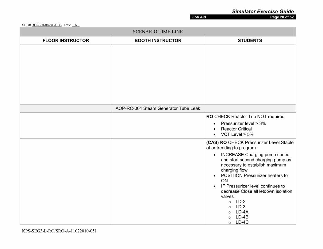
Simulator Exercise Guide SEG# ROI/SOI-06-SE-SC3 Rev: A
KPS-SEG3-L-RO/SRO-A-11022010-051
Job Aid Page 20 of 52
SCENARIO TIME LINE
FLOOR INSTRUCTOR BOOTH INSTRUCTOR STUDENTS
AOP-RC-004 Steam Generator Tube Leak
RO CHECK Reactor Trip NOT required • Pressurizer level > 3% • Reactor Critical • VCT Level > 5%
(CAS) RO CHECK Pressurizer Level Stable at or trending to program
• INCREASE Charging pump speed and start second charging pump as necessary to establish maximum charging flow
• POSITION Pressurizer heaters to ON
• IF Pressurizer level continues to decrease Close all letdown isolation valves
o LD-2 o LD-3 o LD-4A o LD-4B o LD-4C
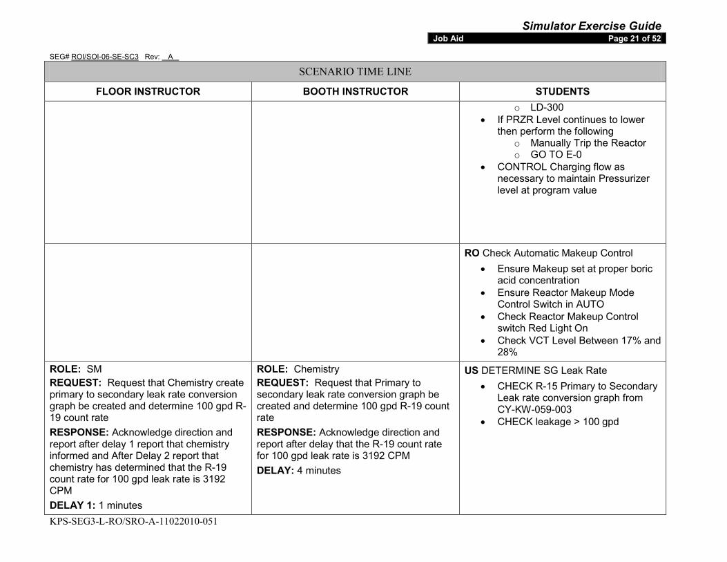
Simulator Exercise Guide SEG# ROI/SOI-06-SE-SC3 Rev: A
KPS-SEG3-L-RO/SRO-A-11022010-051
Job Aid Page 21 of 52
SCENARIO TIME LINE
FLOOR INSTRUCTOR BOOTH INSTRUCTOR STUDENTS o LD-300
• If PRZR Level continues to lower then perform the following
o Manually Trip the Reactor o GO TO E-0
• CONTROL Charging flow as necessary to maintain Pressurizer level at program value
RO Check Automatic Makeup Control • Ensure Makeup set at proper boric
acid concentration • Ensure Reactor Makeup Mode
Control Switch in AUTO • Check Reactor Makeup Control
switch Red Light On • Check VCT Level Between 17% and
28% ROLE: SM REQUEST: Request that Chemistry create primary to secondary leak rate conversion graph be created and determine 100 gpd R-19 count rate RESPONSE: Acknowledge direction and report after delay 1 report that chemistry informed and After Delay 2 report that chemistry has determined that the R-19 count rate for 100 gpd leak rate is 3192 CPM DELAY 1: 1 minutes
ROLE: Chemistry REQUEST: Request that Primary to secondary leak rate conversion graph be created and determine 100 gpd R-19 count rate RESPONSE: Acknowledge direction and report after delay that the R-19 count rate for 100 gpd leak rate is 3192 CPM DELAY: 4 minutes
US DETERMINE SG Leak Rate • CHECK R-15 Primary to Secondary
Leak rate conversion graph from CY-KW-059-003
• CHECK leakage > 100 gpd
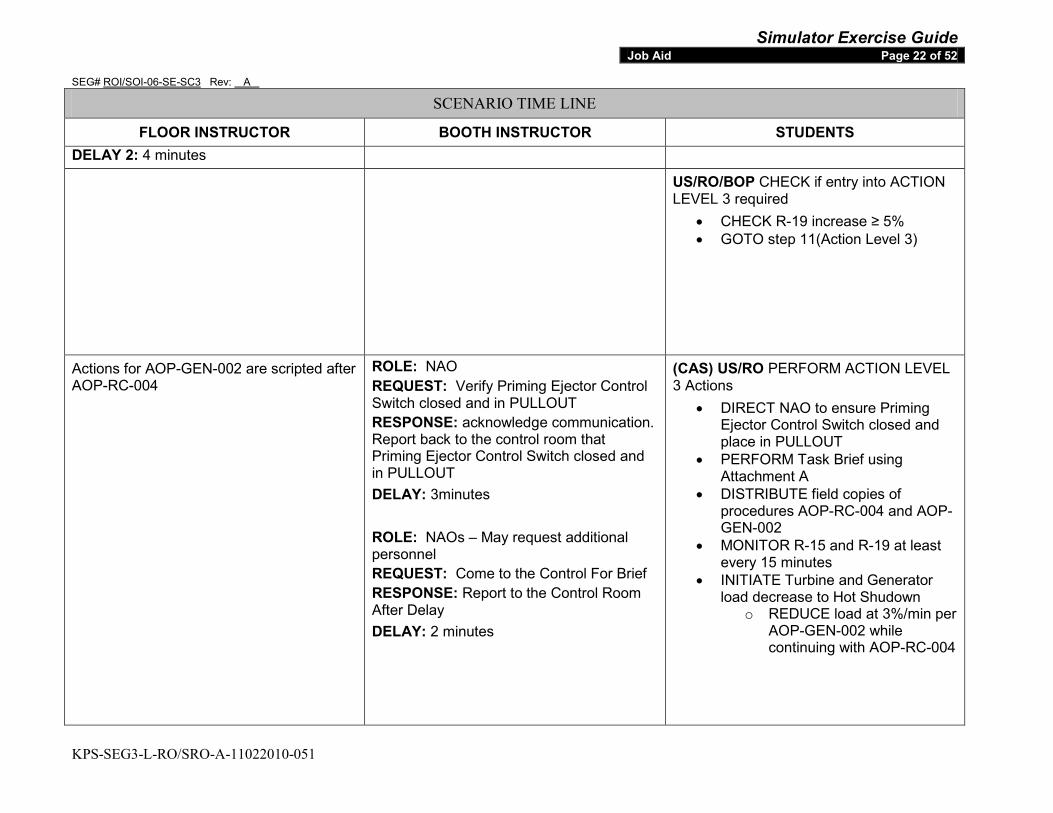
Simulator Exercise Guide SEG# ROI/SOI-06-SE-SC3 Rev: A
KPS-SEG3-L-RO/SRO-A-11022010-051
Job Aid Page 22 of 52
SCENARIO TIME LINE
FLOOR INSTRUCTOR BOOTH INSTRUCTOR STUDENTS DELAY 2: 4 minutes
US/RO/BOP CHECK if entry into ACTION LEVEL 3 required
• CHECK R-19 increase ≥ 5% • GOTO step 11(Action Level 3)
Actions for AOP-GEN-002 are scripted after AOP-RC-004
ROLE: NAO REQUEST: Verify Priming Ejector Control Switch closed and in PULLOUT RESPONSE: acknowledge communication. Report back to the control room that Priming Ejector Control Switch closed and in PULLOUT DELAY: 3minutes ROLE: NAOs – May request additional personnel REQUEST: Come to the Control For Brief RESPONSE: Report to the Control Room After Delay DELAY: 2 minutes
(CAS) US/RO PERFORM ACTION LEVEL 3 Actions
• DIRECT NAO to ensure Priming Ejector Control Switch closed and place in PULLOUT
• PERFORM Task Brief using Attachment A
• DISTRIBUTE field copies of procedures AOP-RC-004 and AOP-GEN-002
• MONITOR R-15 and R-19 at least every 15 minutes
• INITIATE Turbine and Generator load decrease to Hot Shudown
o REDUCE load at 3%/min per AOP-GEN-002 while continuing with AOP-RC-004

Simulator Exercise Guide SEG# ROI/SOI-06-SE-SC3 Rev: A
KPS-SEG3-L-RO/SRO-A-11022010-051
Job Aid Page 23 of 52
SCENARIO TIME LINE
FLOOR INSTRUCTOR BOOTH INSTRUCTOR STUDENTS ROLE: SM REQUEST: Chemistry Sample SGs and perform an accelerated count rate RESPONSE: Acknowledge the direction (The unit will trip prior to report for sample results) and inform after delay that chemistry has been given the direction to sample SGs and perform and accelerated count DELAY: One Minute ROLE: SM REQUEST: RP survey SG Blowdown CIC Ion Exchanger Resin Column for indications above background using held radiation monitor RESPONSE: After Delay 1 report that RP is informed to perform the requested survey and after delay 2 report survey has been and SG B Blowdown CIC Ion Exchanger column if greater than background and elevated DELAY 1: 1 minutes DELAY 2: 5 minutes
ROLE: Chemistry REQUEST: Sample SGs and perform an accelerated count rate RESPONSE: Acknowledge the direction (The unit will trip prior to report for sample results) DELAY: N/A ROLE: RP REQUEST: Survey SG Blowdown CIC Ion Exchanger Resin Column for indications above background using held radiation monitor RESPONSE: Acknowledge the direction and after delay report that SG B Blowdown CIC Ion Exchanger column if greater than background and elevated DELAY: 5 minutes
US (CAS) IDENTIFY leaking Steam Generator
• DIRECT Chemistry to sample and perform accelerated count
• SURVEY SG Blowdown CIC Ion Exchange Resin Column for indications
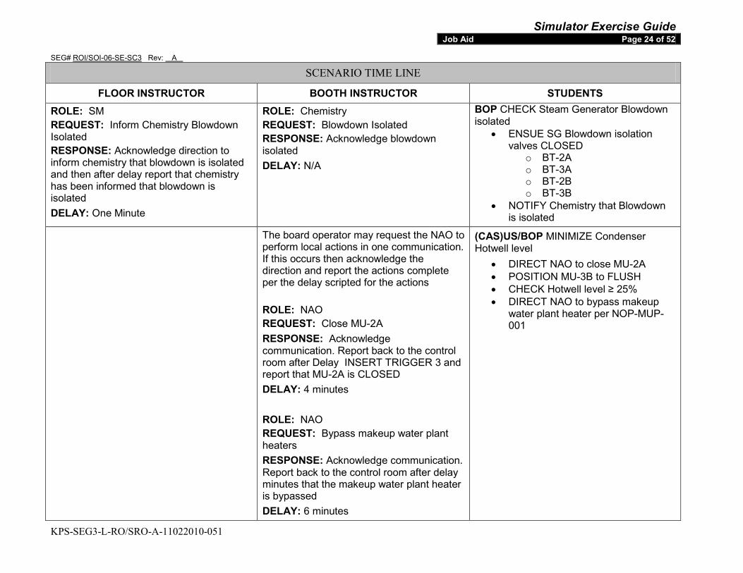
Simulator Exercise Guide SEG# ROI/SOI-06-SE-SC3 Rev: A
KPS-SEG3-L-RO/SRO-A-11022010-051
Job Aid Page 24 of 52
SCENARIO TIME LINE
FLOOR INSTRUCTOR BOOTH INSTRUCTOR STUDENTS ROLE: SM REQUEST: Inform Chemistry Blowdown Isolated RESPONSE: Acknowledge direction to inform chemistry that blowdown is isolated and then after delay report that chemistry has been informed that blowdown is isolated DELAY: One Minute
ROLE: Chemistry REQUEST: Blowdown Isolated RESPONSE: Acknowledge blowdown isolated DELAY: N/A
BOP CHECK Steam Generator Blowdown isolated
• ENSUE SG Blowdown isolation valves CLOSED
o BT-2A o BT-3A o BT-2B o BT-3B
• NOTIFY Chemistry that Blowdown is isolated
The board operator may request the NAO to perform local actions in one communication. If this occurs then acknowledge the direction and report the actions complete per the delay scripted for the actions ROLE: NAO REQUEST: Close MU-2A RESPONSE: Acknowledge communication. Report back to the control room after Delay INSERT TRIGGER 3 and report that MU-2A is CLOSED DELAY: 4 minutes ROLE: NAO REQUEST: Bypass makeup water plant heaters RESPONSE: Acknowledge communication. Report back to the control room after delay minutes that the makeup water plant heater is bypassed DELAY: 6 minutes
(CAS)US/BOP MINIMIZE Condenser Hotwell level
• DIRECT NAO to close MU-2A • POSITION MU-3B to FLUSH • CHECK Hotwell level ≥ 25% • DIRECT NAO to bypass makeup
water plant heater per NOP-MUP-001
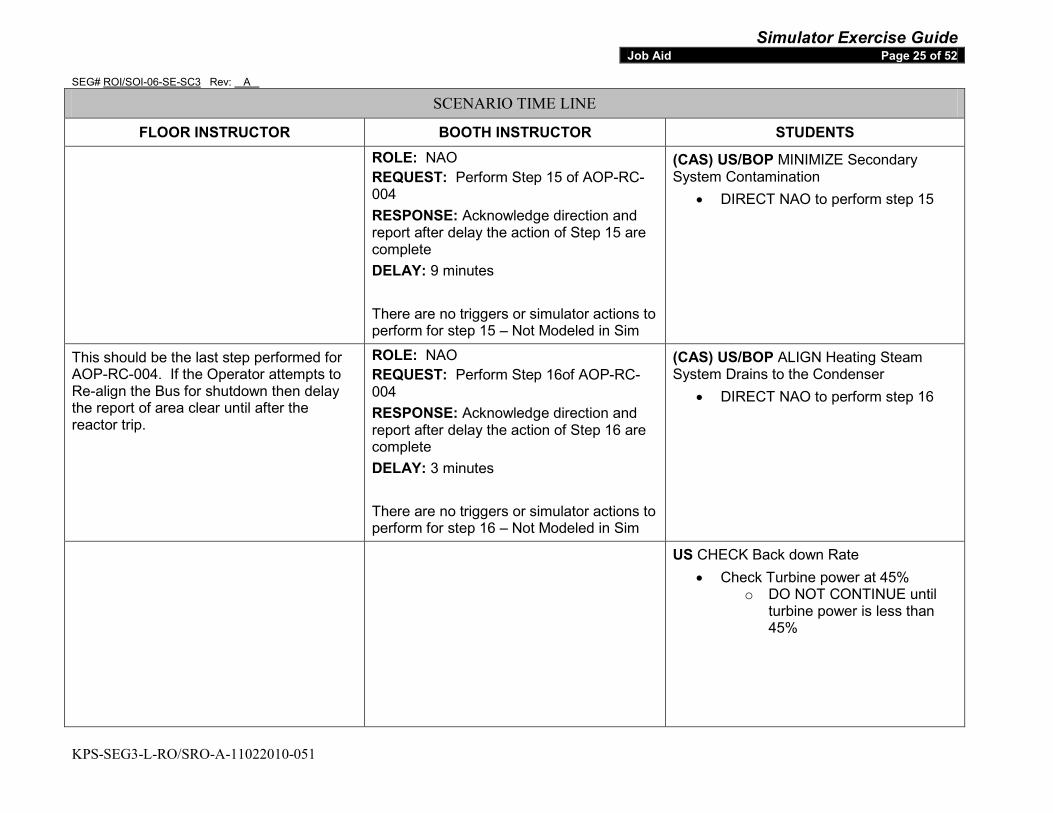
Simulator Exercise Guide SEG# ROI/SOI-06-SE-SC3 Rev: A
KPS-SEG3-L-RO/SRO-A-11022010-051
Job Aid Page 25 of 52
SCENARIO TIME LINE
FLOOR INSTRUCTOR BOOTH INSTRUCTOR STUDENTS
ROLE: NAO REQUEST: Perform Step 15 of AOP-RC-004 RESPONSE: Acknowledge direction and report after delay the action of Step 15 are complete DELAY: 9 minutes There are no triggers or simulator actions to perform for step 15 – Not Modeled in Sim
(CAS) US/BOP MINIMIZE Secondary System Contamination
• DIRECT NAO to perform step 15
This should be the last step performed for AOP-RC-004. If the Operator attempts to Re-align the Bus for shutdown then delay the report of area clear until after the reactor trip.
ROLE: NAO REQUEST: Perform Step 16of AOP-RC-004 RESPONSE: Acknowledge direction and report after delay the action of Step 16 are complete DELAY: 3 minutes There are no triggers or simulator actions to perform for step 16 – Not Modeled in Sim
(CAS) US/BOP ALIGN Heating Steam System Drains to the Condenser
• DIRECT NAO to perform step 16
US CHECK Back down Rate • Check Turbine power at 45%
o DO NOT CONTINUE until turbine power is less than 45%
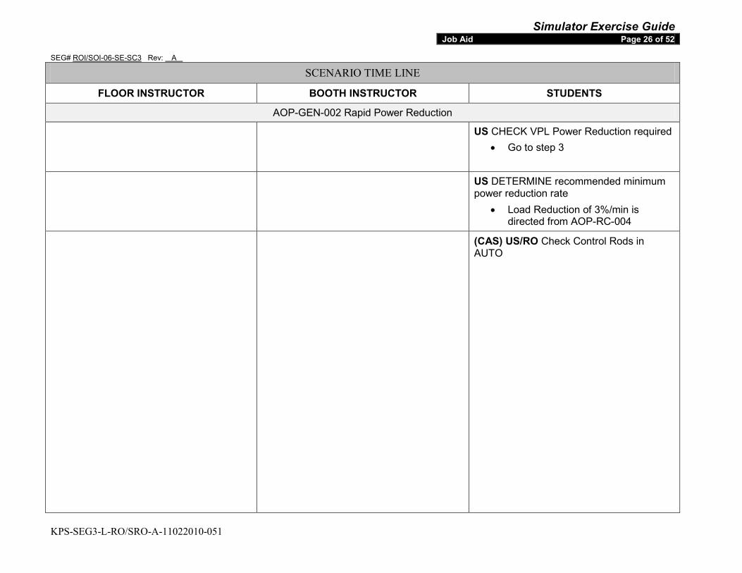
Simulator Exercise Guide SEG# ROI/SOI-06-SE-SC3 Rev: A
KPS-SEG3-L-RO/SRO-A-11022010-051
Job Aid Page 26 of 52
SCENARIO TIME LINE
FLOOR INSTRUCTOR BOOTH INSTRUCTOR STUDENTS
AOP-GEN-002 Rapid Power Reduction
US CHECK VPL Power Reduction required • Go to step 3
US DETERMINE recommended minimum power reduction rate
• Load Reduction of 3%/min is directed from AOP-RC-004
(CAS) US/RO Check Control Rods in AUTO
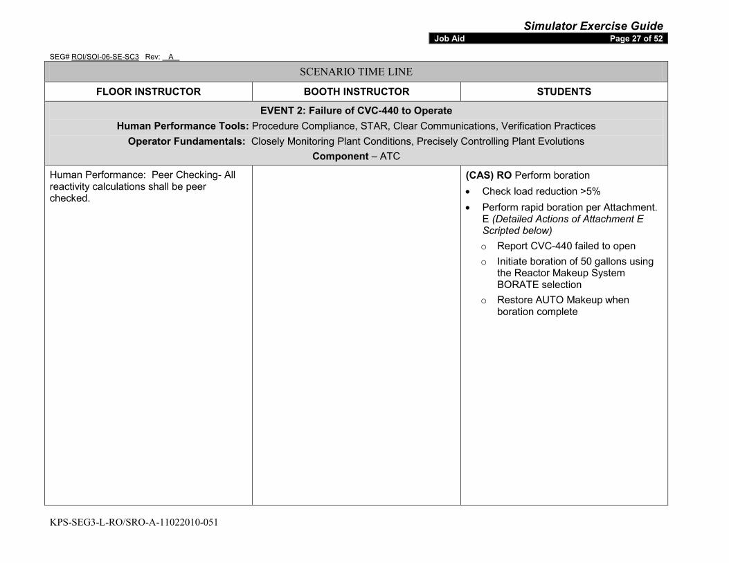
Simulator Exercise Guide SEG# ROI/SOI-06-SE-SC3 Rev: A
KPS-SEG3-L-RO/SRO-A-11022010-051
Job Aid Page 27 of 52
SCENARIO TIME LINE
FLOOR INSTRUCTOR BOOTH INSTRUCTOR STUDENTS
EVENT 2: Failure of CVC-440 to Operate Human Performance Tools: Procedure Compliance, STAR, Clear Communications, Verification Practices
Operator Fundamentals: Closely Monitoring Plant Conditions, Precisely Controlling Plant Evolutions Component – ATC
Human Performance: Peer Checking- All reactivity calculations shall be peer checked.
(CAS) RO Perform boration • Check load reduction >5% • Perform rapid boration per Attachment.
E (Detailed Actions of Attachment E Scripted below) o Report CVC-440 failed to open o Initiate boration of 50 gallons using
the Reactor Makeup System BORATE selection
o Restore AUTO Makeup when boration complete
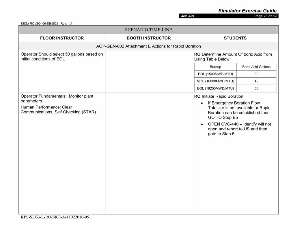
Simulator Exercise Guide SEG# ROI/SOI-06-SE-SC3 Rev: A
KPS-SEG3-L-RO/SRO-A-11022010-051
Job Aid Page 28 of 52
SCENARIO TIME LINE
FLOOR INSTRUCTOR BOOTH INSTRUCTOR STUDENTS
AOP-GEN-002 Attachment E Actions for Rapid Boration
Operator Should select 50 gallons based on initial conditions of EOL
RO Determine Amount Of boric Acid from Using Table Below
Burnup Boric Acid Gallons
BOL (1500MWD/MTU) 30
MOL (10000MWD/MTU) 40
EOL (18250MWD/MTU) 50
Operator Fundamentals: Monitor plant parameters Human Performance: Clear Communications, Self Checking (STAR)
RO Initiate Rapid Boration • If Emergency Boration Flow
Totalizer is not available or Rapid Boration can be established then GO TO Step E5
• OPEN CVC-440 – Identify will not open and report to US and then goto to Step 5
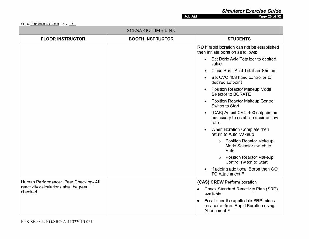
Simulator Exercise Guide SEG# ROI/SOI-06-SE-SC3 Rev: A
KPS-SEG3-L-RO/SRO-A-11022010-051
Job Aid Page 29 of 52
SCENARIO TIME LINE
FLOOR INSTRUCTOR BOOTH INSTRUCTOR STUDENTS
RO If rapid boration can not be established then initiate boration as follows:
• Set Boric Acid Totalizer to desired value
• Close Boric Acid Totalizer Shutter • Set CVC-403 hand controller to
desired setpoint • Position Reactor Makeup Mode
Selector to BORATE • Position Reactor Makeup Control
Switch to Start • (CAS) Adjust CVC-403 setpoint as
necessary to establish desired flow rate
• When Boration Complete then return to Auto Makeup
o Position Reactor Makeup Mode Selector switch to Auto
o Position Reactor Makeup Control switch to Start
• If adding additional Boron then GO TO Attachment F
Human Performance: Peer Checking- All reactivity calculations shall be peer checked.
(CAS) CREW Perform boration • Check Standard Reactivity Plan (SRP)
available • Borate per the applicable SRP minus
any boron from Rapid Boration using Attachment F
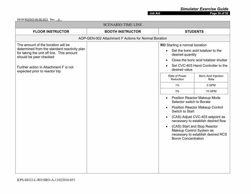
Simulator Exercise Guide SEG# ROI/SOI-06-SE-SC3 Rev: A
KPS-SEG3-L-RO/SRO-A-11022010-051
Job Aid Page 30 of 52
SCENARIO TIME LINE
FLOOR INSTRUCTOR BOOTH INSTRUCTOR STUDENTS
AOP-GEN-002 Attachment F Actions for Normal Boration
The amount of the boration will be determined from the standard reactivity plan for taking the unit off line. This amount should be peer checked Further action in Attachment F is not expected prior to reactor trip
RO Starting a normal boration • Set the boric acid totalizer to the
desired quantity • Close the boric acid totalizer shutter • Set CVC-403 Hand Controller to the
desired value
Rate of Power Reduction
Boric Acid Injection Rate
1% 5 GPM
3% 10 GPM
• Position Reactor Makeup Mode Selector switch to Borate
• Position Reactor Makeup Control Switch to Start
• (CAS) Adjust CVC-403 setpoint as necessary to establish desired flow
• (CAS) Start and Stop Reactor Makeup Control System as necessary to establish desired RCS Boron Concentration
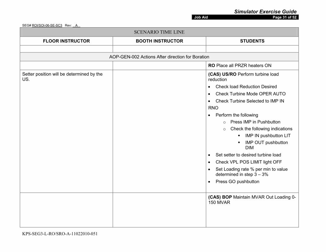
Simulator Exercise Guide SEG# ROI/SOI-06-SE-SC3 Rev: A
KPS-SEG3-L-RO/SRO-A-11022010-051
Job Aid Page 31 of 52
SCENARIO TIME LINE
FLOOR INSTRUCTOR BOOTH INSTRUCTOR STUDENTS
AOP-GEN-002 Actions After direction for Boration
RO Place all PRZR heaters ON
Setter position will be determined by the US.
(CAS) US/RO Perform turbine load reduction • Check load Reduction Desired • Check Turbine Mode OPER AUTO • Check Turbine Selected to IMP IN RNO • Perform the following
o Press IMP in Pushbutton o Check the following indications
IMP IN pushbutton LIT IMP OUT pushbutton
DIM • Set setter to desired turbine load • Check VPL POS LIMIT light OFF • Set Loading rate % per min to value
determined in step 3 – 3% • Press GO pushbutton
(CAS) BOP Maintain MVAR Out Loading 0-150 MVAR
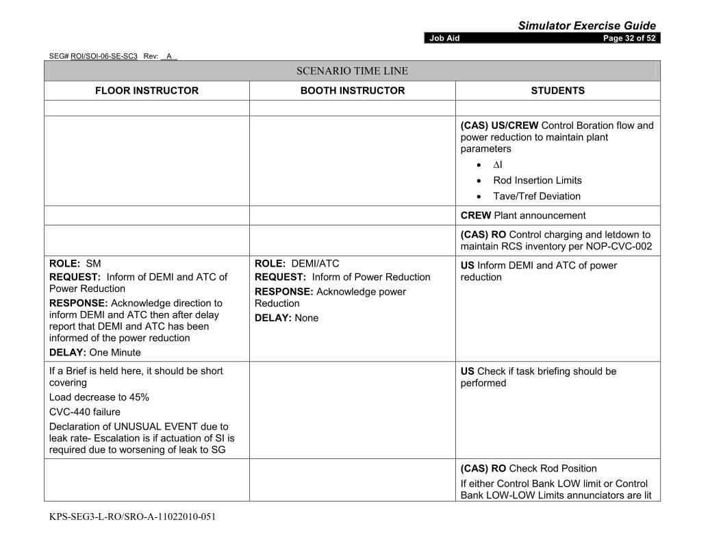
Simulator Exercise Guide SEG# ROI/SOI-06-SE-SC3 Rev: A
KPS-SEG3-L-RO/SRO-A-11022010-051
Job Aid Page 32 of 52
SCENARIO TIME LINE
FLOOR INSTRUCTOR BOOTH INSTRUCTOR STUDENTS
(CAS) US/CREW Control Boration flow and power reduction to maintain plant parameters
• ∆I • Rod Insertion Limits • Tave/Tref Deviation
CREW Plant announcement
(CAS) RO Control charging and letdown to maintain RCS inventory per NOP-CVC-002
ROLE: SM REQUEST: Inform of DEMI and ATC of Power Reduction RESPONSE: Acknowledge direction to inform DEMI and ATC then after delay report that DEMI and ATC has been informed of the power reduction DELAY: One Minute
ROLE: DEMI/ATC REQUEST: Inform of Power Reduction RESPONSE: Acknowledge power Reduction DELAY: None
US Inform DEMI and ATC of power reduction
If a Brief is held here, it should be short covering Load decrease to 45% CVC-440 failure Declaration of UNUSUAL EVENT due to leak rate- Escalation is if actuation of SI is required due to worsening of leak to SG
US Check if task briefing should be performed
(CAS) RO Check Rod Position If either Control Bank LOW limit or Control Bank LOW-LOW Limits annunciators are lit

Simulator Exercise Guide SEG# ROI/SOI-06-SE-SC3 Rev: A
KPS-SEG3-L-RO/SRO-A-11022010-051
Job Aid Page 33 of 52
SCENARIO TIME LINE
FLOOR INSTRUCTOR BOOTH INSTRUCTOR STUDENTS then continue boration
US/RO If Control Bank LOW-LOW Limits annunciator actuates, address Technical Specifications – Determine if rods actually below RILs LCO 3.1.6 Condition A • Required Action A.1.1. Verify SDM
within limits within one hour OR
• Required Actions; o A.1.2 Initiate boration to restore
SDM within limits within 1 hour AND
o A.2 Restore control bank to within limits within 2 hours
(CAS) CREW Control Tavg/Tref Deviation • Check Control Rods move as
necessary to restore Tave/Trev deviation
• Check status light load loss 10 PCT Rate LIT
• Check Tavg > 540ºF CREW Perform a review of SER Points as
time permits
(CAS) Check Control Systems Operating in Automatic
• SG Level • PRZR Press Control • PRZR Level Control
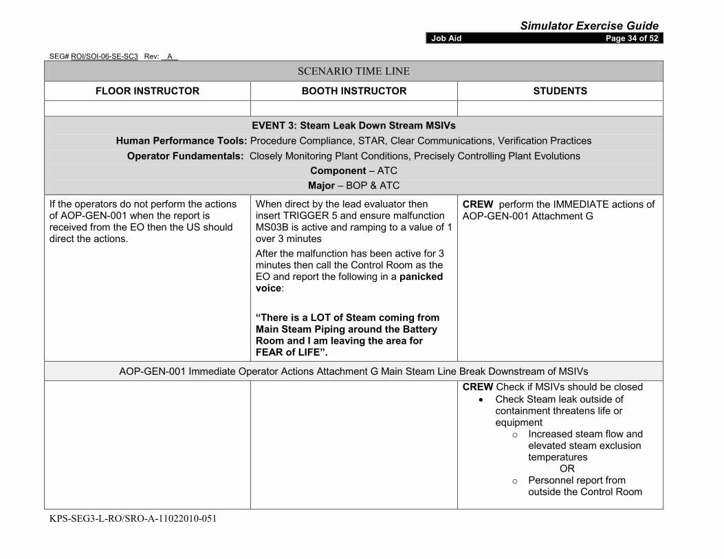
Simulator Exercise Guide SEG# ROI/SOI-06-SE-SC3 Rev: A
KPS-SEG3-L-RO/SRO-A-11022010-051
Job Aid Page 34 of 52
SCENARIO TIME LINE
FLOOR INSTRUCTOR BOOTH INSTRUCTOR STUDENTS
EVENT 3: Steam Leak Down Stream MSIVs Human Performance Tools: Procedure Compliance, STAR, Clear Communications, Verification Practices
Operator Fundamentals: Closely Monitoring Plant Conditions, Precisely Controlling Plant Evolutions Component – ATC Major – BOP & ATC
If the operators do not perform the actions of AOP-GEN-001 when the report is received from the EO then the US should direct the actions.
When direct by the lead evaluator then insert TRIGGER 5 and ensure malfunction MS03B is active and ramping to a value of 1 over 3 minutes After the malfunction has been active for 3 minutes then call the Control Room as the EO and report the following in a panicked voice: “There is a LOT of Steam coming from Main Steam Piping around the Battery Room and I am leaving the area for FEAR of LIFE”.
CREW perform the IMMEDIATE actions of AOP-GEN-001 Attachment G
AOP-GEN-001 Immediate Operator Actions Attachment G Main Steam Line Break Downstream of MSIVs
CREW Check if MSIVs should be closed • Check Steam leak outside of
containment threatens life or equipment
o Increased steam flow and elevated steam exclusion temperatures
OR o Personnel report from
outside the Control Room

Simulator Exercise Guide SEG# ROI/SOI-06-SE-SC3 Rev: A
KPS-SEG3-L-RO/SRO-A-11022010-051
Job Aid Page 35 of 52
SCENARIO TIME LINE
FLOOR INSTRUCTOR BOOTH INSTRUCTOR STUDENTS
RO Manually Trip the Reactor
EVENT 4: SG B Safety Fails Open when MSIVs Close Human Performance Tools: Procedure Compliance, STAR, Clear Communications, Verification Practices
Operator Fundamentals: Closely Monitoring Plant Conditions, Precisely Controlling Plant Evolutions Component – BOP Major – BOP & ATC
The failure of SG B safety open will cause conditions for safety injection. The crew may manually initiate a safety injection depending on plant conditions at the time of the step in E-0
This event happens automatically when the BOP closes the MSIVs ENSURE malfunction MS04B is active when MS-1B goes closed Trigger 7 should activate
BOP CLOSE both MSIVs • MS-1A for SG A • MS-1B for SG B
US Direct the crew to perform the immediate actions of E-0
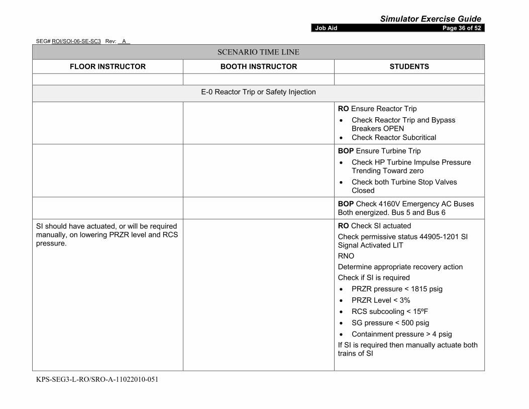
Simulator Exercise Guide SEG# ROI/SOI-06-SE-SC3 Rev: A
KPS-SEG3-L-RO/SRO-A-11022010-051
Job Aid Page 36 of 52
SCENARIO TIME LINE
FLOOR INSTRUCTOR BOOTH INSTRUCTOR STUDENTS
E-0 Reactor Trip or Safety Injection
RO Ensure Reactor Trip • Check Reactor Trip and Bypass
Breakers OPEN • Check Reactor Subcritical
BOP Ensure Turbine Trip • Check HP Turbine Impulse Pressure
Trending Toward zero • Check both Turbine Stop Valves
Closed
BOP Check 4160V Emergency AC Buses Both energized. Bus 5 and Bus 6
SI should have actuated, or will be required manually, on lowering PRZR level and RCS pressure.
RO Check SI actuated Check permissive status 44905-1201 SI Signal Activated LIT RNO Determine appropriate recovery action Check if SI is required • PRZR pressure < 1815 psig • PRZR Level < 3% • RCS subcooling < 15ºF • SG pressure < 500 psig • Containment pressure > 4 psig If SI is required then manually actuate both trains of SI
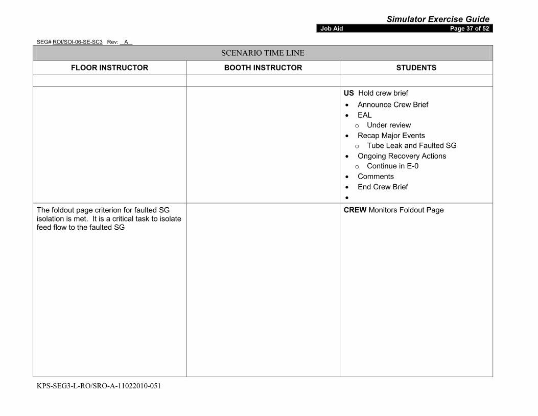
Simulator Exercise Guide SEG# ROI/SOI-06-SE-SC3 Rev: A
KPS-SEG3-L-RO/SRO-A-11022010-051
Job Aid Page 37 of 52
SCENARIO TIME LINE
FLOOR INSTRUCTOR BOOTH INSTRUCTOR STUDENTS
US Hold crew brief • Announce Crew Brief • EAL
o Under review • Recap Major Events
o Tube Leak and Faulted SG • Ongoing Recovery Actions
o Continue in E-0 • Comments • End Crew Brief •
The foldout page criterion for faulted SG isolation is met. It is a critical task to isolate feed flow to the faulted SG
CREW Monitors Foldout Page

Simulator Exercise Guide SEG# ROI/SOI-06-SE-SC3 Rev: A
KPS-SEG3-L-RO/SRO-A-11022010-051
Job Aid Page 38 of 52
SCENARIO TIME LINE
FLOOR INSTRUCTOR BOOTH INSTRUCTOR STUDENTS
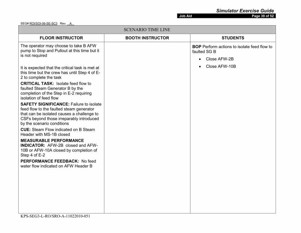
Simulator Exercise Guide SEG# ROI/SOI-06-SE-SC3 Rev: A
KPS-SEG3-L-RO/SRO-A-11022010-051
Job Aid Page 39 of 52
SCENARIO TIME LINE
FLOOR INSTRUCTOR BOOTH INSTRUCTOR STUDENTS
The operator may choose to take B AFW pump to Stop and Pullout at this time but it is not required It is expected that the critical task is met at this time but the crew has until Step 4 of E-2 to complete the task CRITICAL TASK: Isolate feed flow to faulted Steam Generator B by the completion of the Step in E-2 requiring isolation of feed flow SAFETY SIGNIFICANCE: Failure to isolate feed flow to the faulted steam generator that can be isolated causes a challenge to CSFs beyond those irreparably introduced by the scenario conditions CUE: Steam Flow indicated on B Steam Header with MS-1B closed MEASURABLE PERFORMANCE INDICATOR: AFW-2B closed and AFW-10B or AFW-10A closed by completion of Step 4 of E-2 PERFORMANCE FEEDBACK: No feed water flow indicated on AFW Header B
BOP Perform actions to isolate feed flow to faulted SG B
• Close AFW-2B
• Close AFW-10B
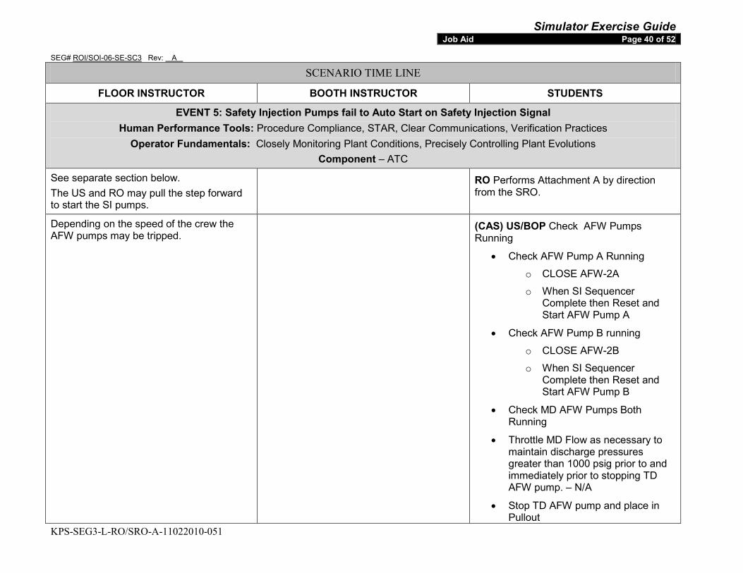
Simulator Exercise Guide SEG# ROI/SOI-06-SE-SC3 Rev: A
KPS-SEG3-L-RO/SRO-A-11022010-051
Job Aid Page 40 of 52
SCENARIO TIME LINE
FLOOR INSTRUCTOR BOOTH INSTRUCTOR STUDENTS
EVENT 5: Safety Injection Pumps fail to Auto Start on Safety Injection Signal Human Performance Tools: Procedure Compliance, STAR, Clear Communications, Verification Practices
Operator Fundamentals: Closely Monitoring Plant Conditions, Precisely Controlling Plant Evolutions Component – ATC
See separate section below. The US and RO may pull the step forward to start the SI pumps.
RO Performs Attachment A by direction from the SRO.
Depending on the speed of the crew the AFW pumps may be tripped.
(CAS) US/BOP Check AFW Pumps Running
• Check AFW Pump A Running
o CLOSE AFW-2A
o When SI Sequencer Complete then Reset and Start AFW Pump A
• Check AFW Pump B running
o CLOSE AFW-2B
o When SI Sequencer Complete then Reset and Start AFW Pump B
• Check MD AFW Pumps Both Running
• Throttle MD Flow as necessary to maintain discharge pressures greater than 1000 psig prior to and immediately prior to stopping TD AFW pump. – N/A
• Stop TD AFW pump and place in Pullout
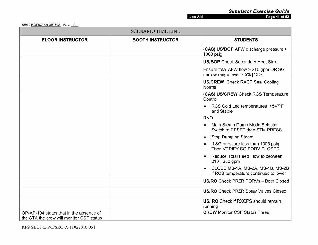
Simulator Exercise Guide SEG# ROI/SOI-06-SE-SC3 Rev: A
KPS-SEG3-L-RO/SRO-A-11022010-051
Job Aid Page 41 of 52
SCENARIO TIME LINE
FLOOR INSTRUCTOR BOOTH INSTRUCTOR STUDENTS
(CAS) US/BOP AFW discharge pressure > 1000 psig
US/BOP Check Secondary Heat Sink
Ensure total AFW flow > 210 gpm OR SG narrow range level > 5% [13%]
US/CREW Check RXCP Seal Cooling Normal
(CAS) US/CREW Check RCS Temperature Control • RCS Cold Leg temperatures <5470
RNO
F and Stable
• Main Steam Dump Mode Selector Switch to RESET then STM PRESS
• Stop Dumping Steam • If SG pressure less than 1005 psig
Then VERIFY SG PORV CLOSED
• Reduce Total Feed Flow to between 210 - 250 gpm
• CLOSE MS-1A, MS-2A, MS-1B, MS-2B if RCS temperature continues to lower
US/RO Check PRZR PORVs – Both Closed
US/RO Check PRZR Spray Valves Closed
US/ RO Check if RXCPS should remain running
OP-AP-104 states that in the absence of the STA the crew will monitor CSF status
CREW Monitor CSF Status Trees

Simulator Exercise Guide SEG# ROI/SOI-06-SE-SC3 Rev: A
KPS-SEG3-L-RO/SRO-A-11022010-051
Job Aid Page 42 of 52
SCENARIO TIME LINE
FLOOR INSTRUCTOR BOOTH INSTRUCTOR STUDENTS trees
CREW Check If any SG is Faulted Check Both SGs
• Any SG pressure Decreasing in uncontrolled manner or completely depressurized
• Do not Continue until Attachment A is complete
• GO TO E-2
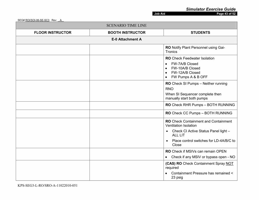
Simulator Exercise Guide SEG# ROI/SOI-06-SE-SC3 Rev: A
KPS-SEG3-L-RO/SRO-A-11022010-051
Job Aid Page 43 of 52
SCENARIO TIME LINE
FLOOR INSTRUCTOR BOOTH INSTRUCTOR STUDENTS
E-0 Attachment A
RO Notify Plant Personnel using Gai-Tronics
RO Check Feedwater Isolation • FW-7A/B Closed • FW-10A/B Closed • FW-12A/B Closed • FW Pumps A & B OFF
RO Check SI Pumps – Neither running RNO When SI Sequencer complete then manually start both pumps
RO Check RHR Pumps – BOTH RUNNING
RO Check CC Pumps – BOTH RUNNING
RO Check Containment and Containment Ventilation Isolation • Check CI Active Status Panel light –
ALL LIT • Place control switches for LD-4A/B/C to
Close
RO Check if MSIVs can remain OPEN • Check if any MSIV or bypass open - NO
(CAS) RO Check Containment Spray NOT
• Containment Pressure has remained < 23 psig
required
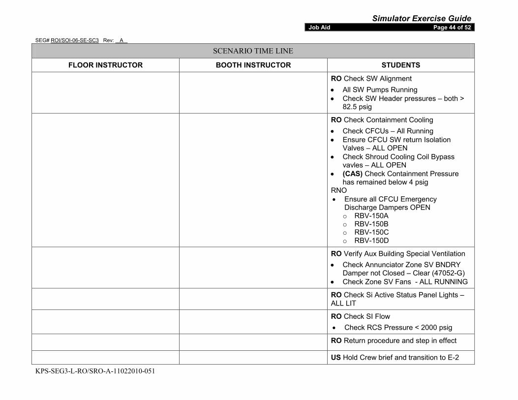
Simulator Exercise Guide SEG# ROI/SOI-06-SE-SC3 Rev: A
KPS-SEG3-L-RO/SRO-A-11022010-051
Job Aid Page 44 of 52
SCENARIO TIME LINE
FLOOR INSTRUCTOR BOOTH INSTRUCTOR STUDENTS
RO Check SW Alignment • All SW Pumps Running • Check SW Header pressures – both >
82.5 psig
RO Check Containment Cooling • Check CFCUs – All Running • Ensure CFCU SW return Isolation
Valves – ALL OPEN • Check Shroud Cooling Coil Bypass
vavles – ALL OPEN • (CAS) Check Containment Pressure
has remained below 4 psig RNO • Ensure all CFCU Emergency
Discharge Dampers OPEN o RBV-150A o RBV-150B o RBV-150C o RBV-150D
RO Verify Aux Building Special Ventilation • Check Annunciator Zone SV BNDRY
Damper not Closed – Clear (47052-G) • Check Zone SV Fans - ALL RUNNING
RO Check Si Active Status Panel Lights – ALL LIT
RO Check SI Flow • Check RCS Pressure < 2000 psig
RO Return procedure and step in effect
US Hold Crew brief and transition to E-2
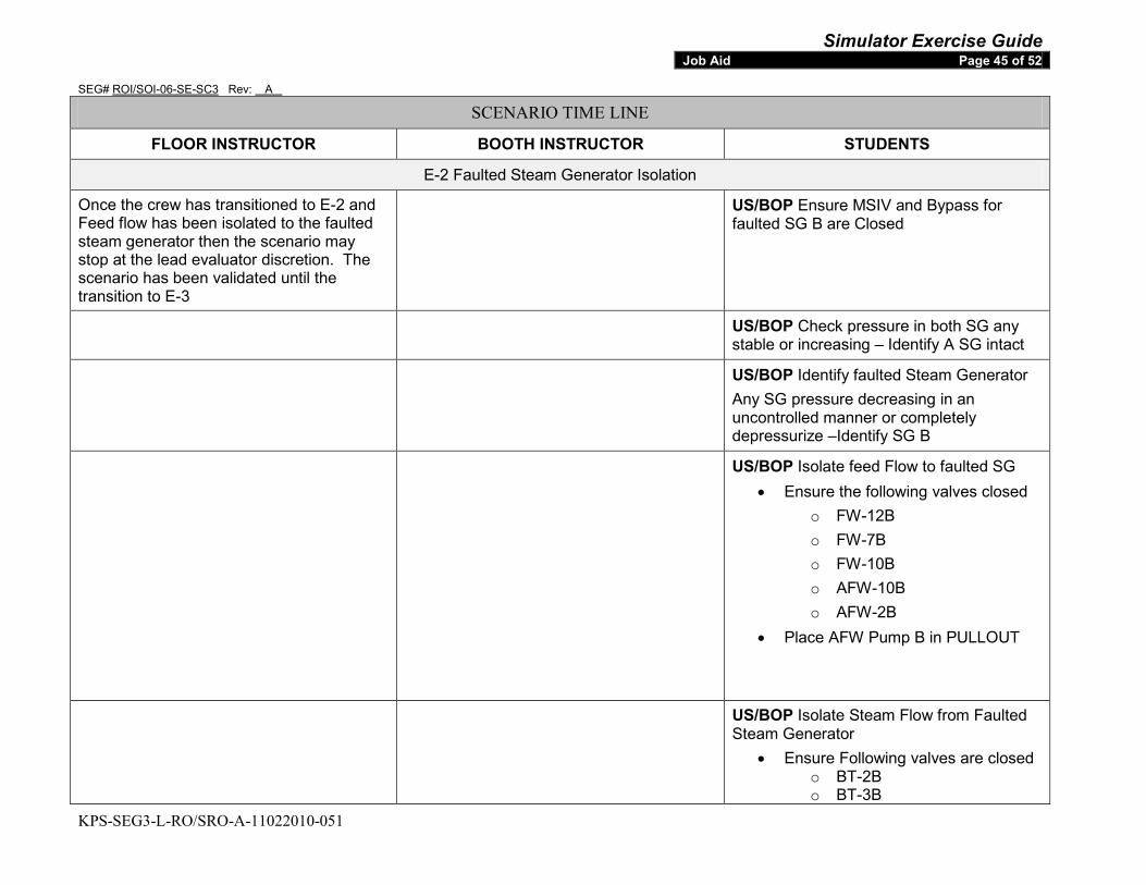
Simulator Exercise Guide SEG# ROI/SOI-06-SE-SC3 Rev: A
KPS-SEG3-L-RO/SRO-A-11022010-051
Job Aid Page 45 of 52
SCENARIO TIME LINE
FLOOR INSTRUCTOR BOOTH INSTRUCTOR STUDENTS
E-2 Faulted Steam Generator Isolation
Once the crew has transitioned to E-2 and Feed flow has been isolated to the faulted steam generator then the scenario may stop at the lead evaluator discretion. The scenario has been validated until the transition to E-3
US/BOP Ensure MSIV and Bypass for faulted SG B are Closed
US/BOP Check pressure in both SG any stable or increasing – Identify A SG intact
US/BOP Identify faulted Steam Generator Any SG pressure decreasing in an uncontrolled manner or completely depressurize –Identify SG B
US/BOP Isolate feed Flow to faulted SG • Ensure the following valves closed
o FW-12B o FW-7B o FW-10B o AFW-10B o AFW-2B
• Place AFW Pump B in PULLOUT
US/BOP Isolate Steam Flow from Faulted Steam Generator
• Ensure Following valves are closed o BT-2B o BT-3B
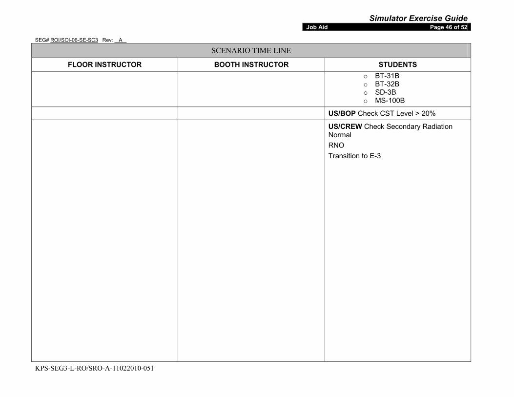
Simulator Exercise Guide SEG# ROI/SOI-06-SE-SC3 Rev: A
KPS-SEG3-L-RO/SRO-A-11022010-051
Job Aid Page 46 of 52
SCENARIO TIME LINE
FLOOR INSTRUCTOR BOOTH INSTRUCTOR STUDENTS o BT-31B o BT-32B o SD-3B o MS-100B
US/BOP Check CST Level > 20%
US/CREW Check Secondary Radiation Normal RNO Transition to E-3

Simulator Exercise Guide SEG# ROI/SOI-06-SE-SC3 Rev: A
KPS-SEG3-L-RO/SRO-A-11022010-051
Job Aid Page 47 of 52
SCENARIO TIME LINE
FLOOR INSTRUCTOR BOOTH INSTRUCTOR STUDENTS
6. SCENARIO END: Ends on transition to E-3 a. FREEZE simulator at direction of floor instructor.
b. STOP DVD recorder. IF this is the last session of the week, THEN
c. STOP Data Capture via Monitor Files (optional)
FINALIZE the DVD (optional)
7. POST-SCENARIO: a. ENSURE simulator problems
encountered during the scenario are documented IAW site specific process.
b. ENSURE training attendance is documented on, Training Attendance Report.
c. SOLICIT/COLLECT trainee feedback
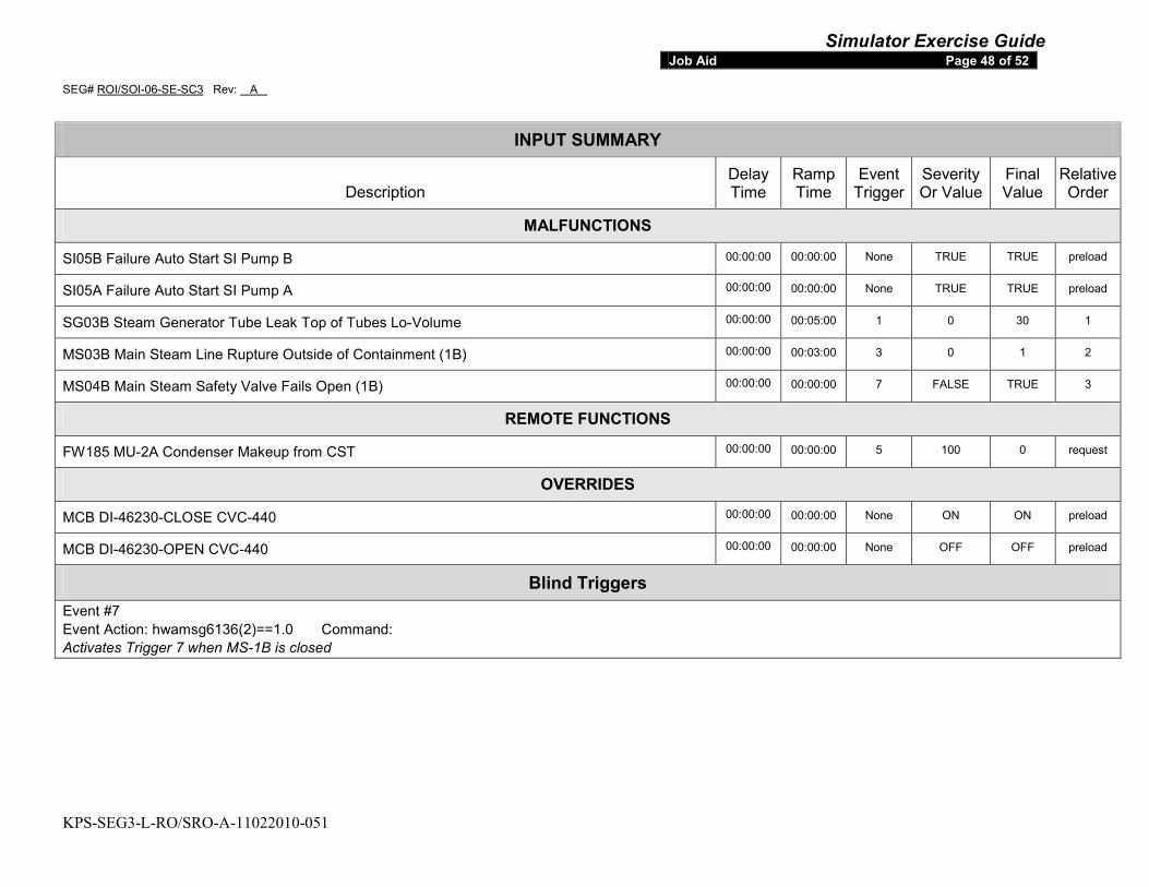
Simulator Exercise Guide SEG# ROI/SOI-06-SE-SC3 Rev: A
KPS-SEG3-L-RO/SRO-A-11022010-051
Job Aid Page 48 of 52
INPUT SUMMARY
Description Delay Time
Ramp Time
Event Trigger
Severity Or Value
Final Value
Relative Order
MALFUNCTIONS
SI05B Failure Auto Start SI Pump B 00:00:00 00:00:00 None TRUE TRUE preload
SI05A Failure Auto Start SI Pump A 00:00:00 00:00:00 None TRUE TRUE preload
SG03B Steam Generator Tube Leak Top of Tubes Lo-Volume 00:00:00 00:05:00 1 0 30 1
MS03B Main Steam Line Rupture Outside of Containment (1B) 00:00:00 00:03:00 3 0 1 2
MS04B Main Steam Safety Valve Fails Open (1B) 00:00:00 00:00:00 7 FALSE TRUE 3
REMOTE FUNCTIONS
FW185 MU-2A Condenser Makeup from CST 00:00:00 00:00:00 5 100 0 request
OVERRIDES
MCB DI-46230-CLOSE CVC-440 00:00:00 00:00:00 None ON ON preload
MCB DI-46230-OPEN CVC-440 00:00:00 00:00:00 None OFF OFF preload
Blind Triggers Event #7 Event Action: hwamsg6136(2)==1.0 Command: Activates Trigger 7 when MS-1B is closed
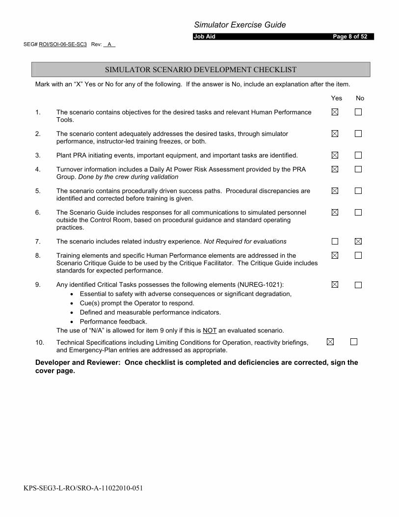
Simulator Exercise Guide Job Aid Page 8 of 52
SEG# ROI/SOI-06-SE-SC3 Rev: A
KPS-SEG3-L-RO/SRO-A-11022010-051
SIMULATOR SCENARIO DEVELOPMENT CHECKLIST
Mark with an “X” Yes or No for any of the following. If the answer is No, include an explanation after the item.
Yes No
1. The scenario contains objectives for the desired tasks and relevant Human Performance Tools.
2. The scenario content adequately addresses the desired tasks, through simulator performance, instructor-led training freezes, or both.
3. Plant PRA initiating events, important equipment, and important tasks are identified.
4. Turnover information includes a Daily At Power Risk Assessment provided by the PRA Group. Done by the crew during validation
5. The scenario contains procedurally driven success paths. Procedural discrepancies are identified and corrected before training is given.
6. The Scenario Guide includes responses for all communications to simulated personnel outside the Control Room, based on procedural guidance and standard operating practices.
7. The scenario includes related industry experience. Not Required for evaluations
8. Training elements and specific Human Performance elements are addressed in the Scenario Critique Guide to be used by the Critique Facilitator. The Critique Guide includes standards for expected performance.
9. Any identified Critical Tasks possesses the following elements (NUREG-1021): • Essential to safety with adverse consequences or significant degradation, • Cue(s) prompt the Operator to respond. • Defined and measurable performance indicators. • Performance feedback.
The use of “N/A” is allowed for item 9 only if this is NOT
an evaluated scenario.
10. Technical Specifications including Limiting Conditions for Operation, reactivity briefings, and Emergency-Plan entries are addressed as appropriate.
Developer and Reviewer: Once checklist is completed and deficiencies are corrected, sign the cover page.
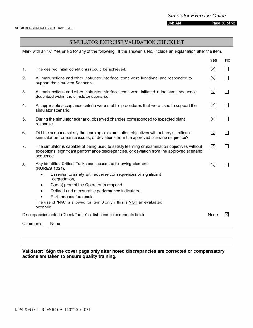
Simulator Exercise Guide Job Aid Page 50 of 52
SEG# ROI/SOI-06-SE-SC3 Rev: A
KPS-SEG3-L-RO/SRO-A-11022010-051
SIMULATOR EXERCISE VALIDATION CHECKLIST
Mark with an “X” Yes or No for any of the following. If the answer is No, include an explanation after the item.
Yes No
1. The desired initial condition(s) could be achieved.
2. All malfunctions and other instructor interface items were functional and responded to support the simulator Scenario.
3. All malfunctions and other instructor interface items were initiated in the same sequence described within the simulator scenario.
4. All applicable acceptance criteria were met for procedures that were used to support the simulator scenario.
5. During the simulator scenario, observed changes corresponded to expected plant response.
6. Did the scenario satisfy the learning or examination objectives without any significant simulator performance issues, or deviations from the approved scenario sequence?
7. The simulator is capable of being used to satisfy learning or examination objectives without exceptions, significant performance discrepancies, or deviation from the approved scenario sequence.
8. Any identified Critical Tasks possesses the following elements (NUREG-1021):
• Essential to safety with adverse consequences or significant degradation,
• Cue(s) prompt the Operator to respond. • Defined and measurable performance indicators. • Performance feedback.
The use of “N/A” is allowed for item 8 only if this is NOT
an evaluated scenario.
Discrepancies noted (Check “none” or list items in comments field) None
Comments: None
Validator: Sign the cover page only after noted discrepancies are corrected or compensatory actions are taken to ensure quality training.
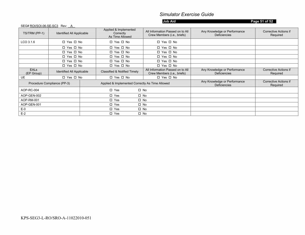
Simulator Exercise Guide Job Aid Page 51 of 52
SEG# ROI/SOI-06-SE-SC3 Rev: A
KPS-SEG3-L-RO/SRO-A-11022010-051
TS/TRM (PP-1) Identified All Applicable Applied & Implemented
Correctly As Time Allowed
All Information Passed on to All Crew Members (i.e., briefs)
Any Knowledge or Performance Deficiencies
Corrective Actions if Required
LCO 3.1.6 Yes No Yes No Yes No
Yes No Yes No Yes No Yes No Yes No Yes No Yes No Yes No Yes No Yes No Yes No Yes No Yes No Yes No Yes No
EALs (EP Group) Identified All Applicable Classified & Notified Timely All Information Passed on to All
Crew Members (i.e., briefs) Any Knowledge or Performance
Deficiencies Corrective Actions if
Required UE Yes No Yes No Yes No
Procedure Compliance (PP-3) Applied & Implemented Correctly As Time Allowed Any Knowledge or Performance Deficiencies
Corrective Actions if Required
AOP-RC-004 Yes No
AOP-GEN-002 Yes No AOP-RM-001 Yes No AOP-GEN-001 Yes No E-0 Yes No E-2 Yes No
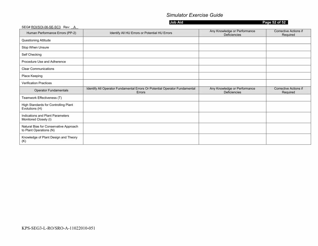
Simulator Exercise Guide Job Aid Page 52 of 52
SEG# ROI/SOI-06-SE-SC3 Rev: A
KPS-SEG3-L-RO/SRO-A-11022010-051
Human Performance Errors (PP-2) Identify All HU Errors or Potential HU Errors Any Knowledge or Performance Deficiencies
Corrective Actions if Required
Questioning Attitude
Stop When Unsure
Self Checking
Procedure Use and Adherence
Clear Communications
Place Keeping
Verification Practices
Operator Fundamentals Identify All Operator Fundamental Errors Or Potential Operator Fundamental Errors
Any Knowledge or Performance Deficiencies
Corrective Actions if Required
Teamwork Effectiveness (T)
High Standards for Controlling Plant Evolutions (H)
Indications and Plant Parameters Monitored Closely (I)
Natural Bias for Conservative Approach to Plant Operations (N)
Knowledge of Plant Design and Theory (K)