Embed Size (px)
Citation preview

PROFIBUSfault finding and health checking
Andy VerwerVerwer Training & Consultancy Ltd
Page 2PROFIBUS: Health checking and fault finding, October 2010
PROFIBUS
� PROFIBUS is a very reliable and cost effective technology.
� It is common to find extensive installations comprising thousands of PROFIBUS devices operating on complex networks which are connected together via industrial Ethernet.
� The reliable operation of these networks is essential to maintaining plant productivity.
� So, what can go wrong?

Page 3PROFIBUS: Health checking and fault finding, October 2010
PROFIBUS PA
PROFInet / Ethernet/TCP-IP
PLC
MBPRS 485 or FO
Manufacturing Process
AS-Interface
PROFIBUS DP
IPC
OS OS
Instrument or I/O failure
Instrument or I/O failure
Device removalDevice removal
Configuration faults.Configuration faults.
?
Addressing faultsAddressing faultsInterference pickup.
Interference pickup.
Wiring faults, reflections, wire breaks, short circuits.
Wiring faults, reflections, wire breaks, short circuits.
The most common PROFIBUS problems
Page 4PROFIBUS: Health checking and fault finding, October 2010
The reliability problem
� To understand the problem that faces system engineers, consider a modest installation with 1000 devices installed:
� Each device might exhibit a mean (average) time to failure of 20 years.
� On average we would therefore expect a failure every 20/1000 years
which is approximately a failure each week!
�We must be able to locate and fix these failures quickly and efficiently.

Page 5PROFIBUS: Health checking and fault finding, October 2010
Fault categorisation
� Operational faults can be categorised in several ways:
Peripheral faults
Communication faults
� Concerned with the sensor or actuator.
� E.g. sensor wire break, loss of output power, sticking valve etc.
� Devices are still communicating
� Faults prevent signals reaching their destination.
� E.g. network wiring errors, interference pickup, reflections etc.
� Communication is disrupted.
Page 6PROFIBUS: Health checking and fault finding, October 2010
Peripheral faults
� Because the communication remains operational, peripheral faults can often be located and diagnosed using the communications system itself.
� Tools and techniques that are useful for locating peripheral faults on PROFIBUS systems include:
�Diagnostic reporting using on-line system diagnostics.
�Engineering tools, protocol analysers, etc.
�Modern intelligent devices incorporate self diagnostic features that can identify and highlight peripheral faults.
� However, tools are still required to access these extended diagnostics.

Page 7PROFIBUS: Health checking and fault finding, October 2010
Communication faults
� Communication faults can be diagnosed using tools such as:
�Protocol analysers and diagnostic tools.
�Waveform visualisation tools such as oscilloscopes etc.
� Communication errors do not always produce loss of control. This is because modern fieldbus technologies are very robust to errors that can corrupt data.
Page 8PROFIBUS: Health checking and fault finding, October 2010
Communication faults
�Quite often users are unaware that their system has communication errors because the robustness of PROFIBUS can hide these faults.
Green light – all must be ok!
� Only when the rate of data corruption reaches a critical threshold will the fault become visible.

Page 9PROFIBUS: Health checking and fault finding, October 2010
Fault categorisation
� Operational faults can therefore be categorised as to their criticality:
Criticalfaults
Non-criticalfaults
� Faults which prevent devices from functioning.
� E.g. sensor wire break, loss of device power, stuck valve, cut network cable etc.
� Can cause loss of production and/or unsafe situations and so must be immediately dealt with.
� Do not immediately prevent devices from working.
� E.g. sensor drift, valve stiction, corroding connections etc.
� Can be tolerated for a short time because the device is still functioning, albeit with reduced accuracy or performance.
Page 10PROFIBUS: Health checking and fault finding, October 2010
Fault categorisation
Installation faults
Fix during commissioning
Criticalfaults
Non-criticalfaults
Operational faults
System Health Check
Fix during normal operation
Production stops –Rapid diagnostics and location required.
How can we detect,
diagnose and locate these
faults?
How do we make sure all is well?

Page 11PROFIBUS: Health checking and fault finding, October 2010
Standard PROFIBUS diagnostics
�Every PROFIBUS device provides a block of standard diagnostics, which provides information on the health of the device.
�Standard diagnostics gives information on the device and the state of communications.
�Standard diagnostics are generally useful for diagnosing communication faults.
Page 12PROFIBUS: Health checking and fault finding, October 2010
SFBF
Sensor
• Device failure• Wiring failure
Actuator
System diagnostics:
Station 41 not ready
#41
Communication faults

Page 13PROFIBUS: Health checking and fault finding, October 2010
SFBF
• Configuration error
#41
Communication faults
System diagnostics:
Station 41
configuration error.
missing module
Page 14PROFIBUS: Health checking and fault finding, October 2010
Extended PROFIBUS diagnostics
�Extended diagnostics can provide information on peripheral errors.
�Peripheral diagnostics are an important part of a successful fault finding and maintenance strategy.
�Extended diagnostics are sent together with the standard diagnostics in the same telegram.

Page 15PROFIBUS: Health checking and fault finding, October 2010
SFBF
Sensor
Actuator
• Sensor failure• Actuator failure
System diagnostics:
Station 41, module 1,
Input channel 1,
sensor fail.
System diagnostics:
Station 41, module 2,
Output channel 0,
Over temperature
#41
Peripheral faults
Page 16PROFIBUS: Health checking and fault finding, October 2010
SFBF
Sensor
Actuator
• Wiring failure
System diagnostics:
Station 41, module 1,
Input channel 1,
Wire break
#41
Peripheral faults

Page 17PROFIBUS: Health checking and fault finding, October 2010
Reflections and Termination
�When electrical signals travel down a cable, any electrical discontinuity like a change in resistance, capacitance or the end of the wire, can cause reflections to occur.
�Just like an echo, the reflected signal can cause multiple signals to appear on the line. Reflections are bad news in high-speed communications because signals are corrupted or distorted by the reflection.
Page 18PROFIBUS: Health checking and fault finding, October 2010
Reflections
�Perhaps the number one problem on PROFIBUS systems is “reflections”.
�Reflections occur whenever we have a discontinuity on the network cable
�To avoid reflections from the ends of the cable we use powered terminations at each end of every segment.
�If the termination is missing or unpowered then reflections can result.
�Spur lines and lots of other conditions can also cause reflections.

Page 19PROFIBUS: Health checking and fault finding, October 2010
Reflections and Termination
� Problems due to reflections can be very difficult to diagnose without the correct tools and a systematic approach.
� The main problem is that the devices that are most affected are often at the opposite end of the segment from the source of the reflection:
Bus fault
Cause of reflection, e.g. stub line
T T
Page 20PROFIBUS: Health checking and fault finding, October 2010
Use of an oscilloscope
�An oscilloscope can provide visualisation of the PROFIBUS waveforms and can help to check the general health of the network.
�However, when combined with an analyser which has an oscilloscope triggering facility, it can enable to exact location of a wide range of device and wiring problems.
�We can determine the exact location of reflection generating faults by measuring the delay from the transmitting station to the reflection.
Page 21PROFIBUS: Health checking and fault finding, October 2010
Reflection Measurement
� Consider the case where an oscilloscope is connected to one end of a segment which has a reflection problem:
XT
� The transmitter will transmit in both directions:
• One travelling directly to the ‘scope over distance “a”,
• The other travelling to the cause of the reflection and back over distance “b + a + b”.
a ba + b
Cause ofReflection
TransmitterOscilloscope
Page 22PROFIBUS: Health checking and fault finding, October 2010
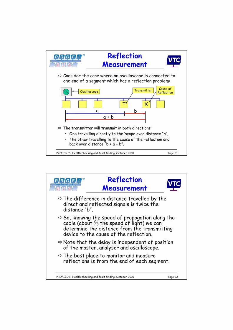
Reflection Measurement
�The difference in distance travelled by the direct and reflected signals is twice the distance “b”.
�So, knowing the speed of propogation along the cable (about the speed of light) we can determine the distance from the transmitting device to the cause of the reflection.
�Note that the delay is independent of position of the master, analyser and oscilloscope.
�The best place to monitor and measure reflections is from the end of each segment.
32

Live Demonstration