Embed Size (px)
Citation preview
Operating Instructions forPROFIBUS-DP Communications Modulesfor Siemens General Purpose Inverters
CB15 CB155
MICROMASTER COMBIMASTERMICROMASTER Vector MICROMASTER IntegratedMIDIMASTER Vector
PROFIBUS-DP Communications ModuleCB15/CB155
Operating Instructions

© Siemens plc 2000 G85139-H1750-U115-B1
2 24/05/00
PAGE LEFT INTENTIONALLY BLANK
English CONTENTS
© Siemens plc 2000 G85139-H1750-U115-B1
3 24/05/00
List of Contents
Warning and Caution Notes 5
1 OVERVIEW 61.1 Description and Features ............................................................................................................... 61.2 Application on a PROFIBUS Link................................................................................................... 61.2.1 Control and operation of the CB15/CB155 via PROFIBUS-DP.............................................. 7
2 INSTALLATION 82.1 CB15 Installation ............................................................................................................................ 92.1.1 Installing the Module ............................................................................................................... 92.1.2 Connecting the Bus Cable ...................................................................................................... 92.1.3 Bus Termination .................................................................................................................... 102.1.4 CB15-Front Panel ................................................................................................................. 102.2 CB155 Installation (6SE9996 –0XA18) ........................................................................................ 112.2.1 Installing the Module ............................................................................................................. 112.2.2 Connecting the Bus Cable .................................................................................................... 122.2.3 Bus Termination .................................................................................................................... 132.3 CB155 Installation (6SE9996 –0XA17) ........................................................................................ 142.3.1 Installing the Module ............................................................................................................. 142.3.2 Connecting the Bus Cable .................................................................................................... 152.3.3 Bus Termination .................................................................................................................... 162.4 EMC Measures............................................................................................................................. 172.4.1 Equipotential Bonding ........................................................................................................... 172.4.2 Cable Installation................................................................................................................... 17
3 OPERATING INFORMATION 183.1 Local Control ................................................................................................................................ 183.2 Remote Control ............................................................................................................................ 183.3 System Parameters...................................................................................................................... 183.3.1 Parameters not Available via the CB15/CB155 .................................................................... 183.3.2 Parameters Specific to the CB15/CB155.............................................................................. 183.3.3 Hex Display for PROFIBUS on CB15 ................................................................................... 19
4 FAULT CODES 20
5 COMMISSIONING 215.1 Data Communication via PROFIBUS-DP .................................................................................... 215.1.1 Parameter Area (PKW) ......................................................................................................... 225.1.2 Rules for Task/Reply Processing.......................................................................................... 245.1.3 Process Data Area (PZD) ..................................................................................................... 255.1.4 Watchdog Timeout ................................................................................................................ 285.2 Settings on the PROFIBUS-DP Master........................................................................................ 295.2.1 Setting the PPO Type from the Master ................................................................................. 295.2.2 Setting the PPO Type on the CB15/CB155 .......................................................................... 295.3 Initial Communication with the CB15/CB155 ............................................................................... 29
6 PROFIBUS TROUBLESHOOTING 306.1 Diagnostic Parameters ................................................................................................................. 306.2 Diagnostics with a Class 2 Master ............................................................................................... 32
English CONTENTS
© Siemens plc 2000 G85139-H1750-U115-B1
4 24/05/00
List of Figures
Figure 1-1: User Data Structure in the PROFIBUS - DP Message Frame................................................... 7Figure 2-1: CB15 Front Panel ..................................................................................................................... 10Figure 2-2 Typical Installation Diagram for CB155 (6SE9996 –0XA18)..................................................... 11Figure 2-3: Diagram of Pin Arrangements for the 5 - way circular PROFIBUS Connector ........................ 12Figure 2-4: Typical Installation Diagrams for CB155 – (6SE9996 –0XA17) ............................................... 14Figure 2-5: Diagram of Terminal Arrangements for CB155 (6SE9996 –0XA17)........................................ 15Figure 2-6: Diagram of CB155 (Issue H model) Terminator Switch set to terminate at both ends. ........... 16Figure 2-7: Diagram of CB155 (Models later than issue H) Terminator Switch.......................................... 16
List of Tables
Table 2-1: CB15 PROFIBUS Transmission Rates and Cabling ................................................................... 9Table 2-2: PROFIBUS Connector Pin Arrangements................................................................................. 12Table 2-3: CB155 PROFIBUS Transmission Rates and Cabling ............................................................... 12Table 2-4: CB155 PROFIBUS Transmission Rates and Cabling ............................................................... 15Table 3-1: CB15/CB155 Parameters .......................................................................................................... 19Table 4-1: CB15/CB155 Fault Codes ......................................................................................................... 20Table 5-1: Structure of the User Data in the PROFIBUS - DP Message Frame ....................................... 21Table 5-2: Parameter Process Data Object (PPO Types) .......................................................................... 21Table 5-3: Structure of the Parameter Area................................................................................................ 22Table 5-4: Task Identifier (Master -- Inverter) ............................................................................................. 22Table 5-5: Reply Identifiers (Inverter - Master) ........................................................................................... 23Table 5-6: Reply Error Codes (Inverter - Master) ....................................................................................... 23Table 5-7: Parameter Identifier Example .................................................................................................... 23Table 5-8: Parameter Value Example......................................................................................................... 24Table 5-9: Process Data Area..................................................................................................................... 25Table 5-10: Bit Word Definition ................................................................................................................... 26Table 5-11: Status Word Definition ............................................................................................................. 27Table 5-12: Value Table for the Identification Bytes ................................................................................... 29Table 6-1: PROFIBUS Diagnostic Parameters........................................................................................... 30
English WARNINGS AND CAUTIONS
© Siemens plc 2000 G85139-H1750-U115-B1
5 24/05/00
Warning and Caution Notes
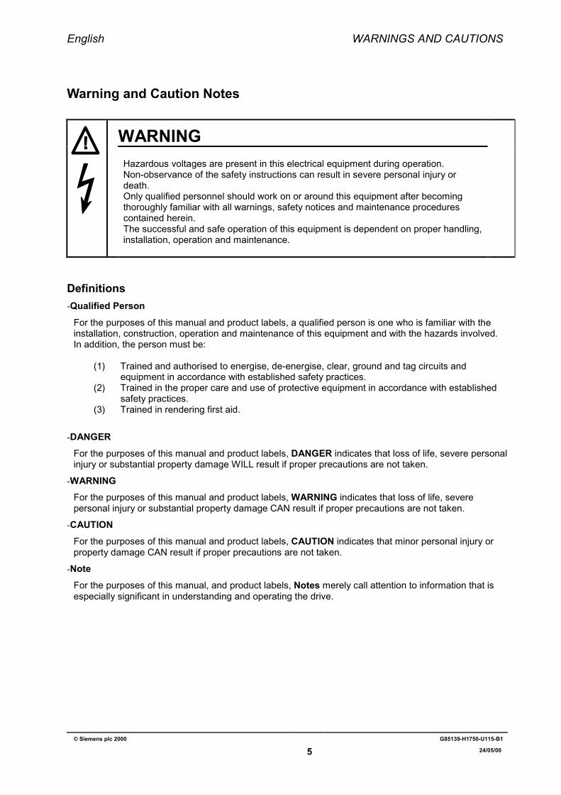
WARNINGHazardous voltages are present in this electrical equipment during operation.Non-observance of the safety instructions can result in severe personal injury ordeath.Only qualified personnel should work on or around this equipment after becomingthoroughly familiar with all warnings, safety notices and maintenance procedurescontained herein.The successful and safe operation of this equipment is dependent on proper handling,installation, operation and maintenance.
Definitions-Qualified Person
For the purposes of this manual and product labels, a qualified person is one who is familiar with theinstallation, construction, operation and maintenance of this equipment and with the hazards involved.In addition, the person must be:
(1) Trained and authorised to energise, de-energise, clear, ground and tag circuits andequipment in accordance with established safety practices.
(2) Trained in the proper care and use of protective equipment in accordance with establishedsafety practices.
(3) Trained in rendering first aid.
-DANGERFor the purposes of this manual and product labels, DANGER indicates that loss of life, severe personalinjury or substantial property damage WILL result if proper precautions are not taken.
-WARNINGFor the purposes of this manual and product labels, WARNING indicates that loss of life, severepersonal injury or substantial property damage CAN result if proper precautions are not taken.
-CAUTIONFor the purposes of this manual and product labels, CAUTION indicates that minor personal injury orproperty damage CAN result if proper precautions are not taken.
-NoteFor the purposes of this manual, and product labels, Notes merely call attention to information that isespecially significant in understanding and operating the drive.
English 1. OVERVIEW
© Siemens plc 2000 G85139-H1750-U115-B1
6 24/05/00
1 OVERVIEW
1.1 Description and Features
The PROFIBUS Module (CB15/CB155) is a device that allows control of an inverter over aPROFIBUS-DP (SINEC L2-DP) serial bus.
The CB15 is for use with MICROMASTER, MICROMASTER VECTOR and MIDIMASTER Vectorinverters.
The CB155 is for use with COMBIMASTER and MICROMASTER Integrated inverters.
Features
- Retains the ability to access the internal parameter set of the inverter (CB15 only).- Allows high-speed cyclical communication over a PROFIBUS link.- Ability to control up to 125 inverters using the PROFIBUS-DP protocol.- Provides open communication conforming to all relevant aspects of DIN19245 Part 3. It may
be used with any other PROFIBUS-DP/SINEC L2-DP peripheral on the serial bus.- Easy to install.- Easy to configure with proprietary Siemens software (parameterisation disc included).- Output frequency (and hence motor speed) can be controlled by one of five methods:
(1) Digital frequency setpoint.(2) Analogue setpoint (voltage or current input).(3) Motor potentiometer.(4) Fixed frequency.(5) Remote data transmission via the PROFIBUS link.
IMPORTANTThe RS485 serial link is not available while the CB15/CB155 is connected tothe inverter.
1.2 Application on a PROFIBUS LinkPROFIBUS-DP is defined as a draft standard in DIN 19245 Part 3. Data communication with theCB15/CB155 conforms to the specifications in the VDI/VDE 3689 ‘ PROFIBUS Profile for VariableSpeed Drives’ guideline. This defines the user data structure through which a master can accessthe drive slaves. The user data structure is subdivided into two areas that can be transmitted ineach message frame:
Process data, i.e. control words and setpoints, or status information and actual values and
A parameter area for reading/writing parameter values, e.g. for reading out faults orinformation on the attributes of a parameter, such as minimum/maximum limits, etc.
The structure of the user data is designated as Parameter Process data Objects (PPO) in thePROFIBUS variable speed drives profile (VDI/VDE guideline 3689). There are five PPO types:user data with no parameter area with two words or six words of process data, or user data with aparameter area and two, six or ten words of process data.
The CB15/CB155 only supports PPO types 1 and 3.
English 1. OVERVIEW
© Siemens plc 2000 G85139-H1750-U115-B1
7 24/05/00
During installation of the network you can configure on the master which PPO type is used toaddress the inverter from the PROFIBUS-DP master. The choice of PPO type depends on the taskof the drive within the automation network. The process data is always transmitted. It is processedwith the highest priority in the shortest time slices. The process data is used for open-loop control ofthe drive in the automation network, e.g. switching on/off, specifying setpoints, etc.
The parameter area provides the user with free access on the network to all the parameters locatedon the inverter, e.g. for reading out detailed diagnostics information, fault messages, etc. Thisenables further information to be called up on a higher-level system, such as a PC, for visualisationof the drive, without affecting the performance capabilities of process data communication.
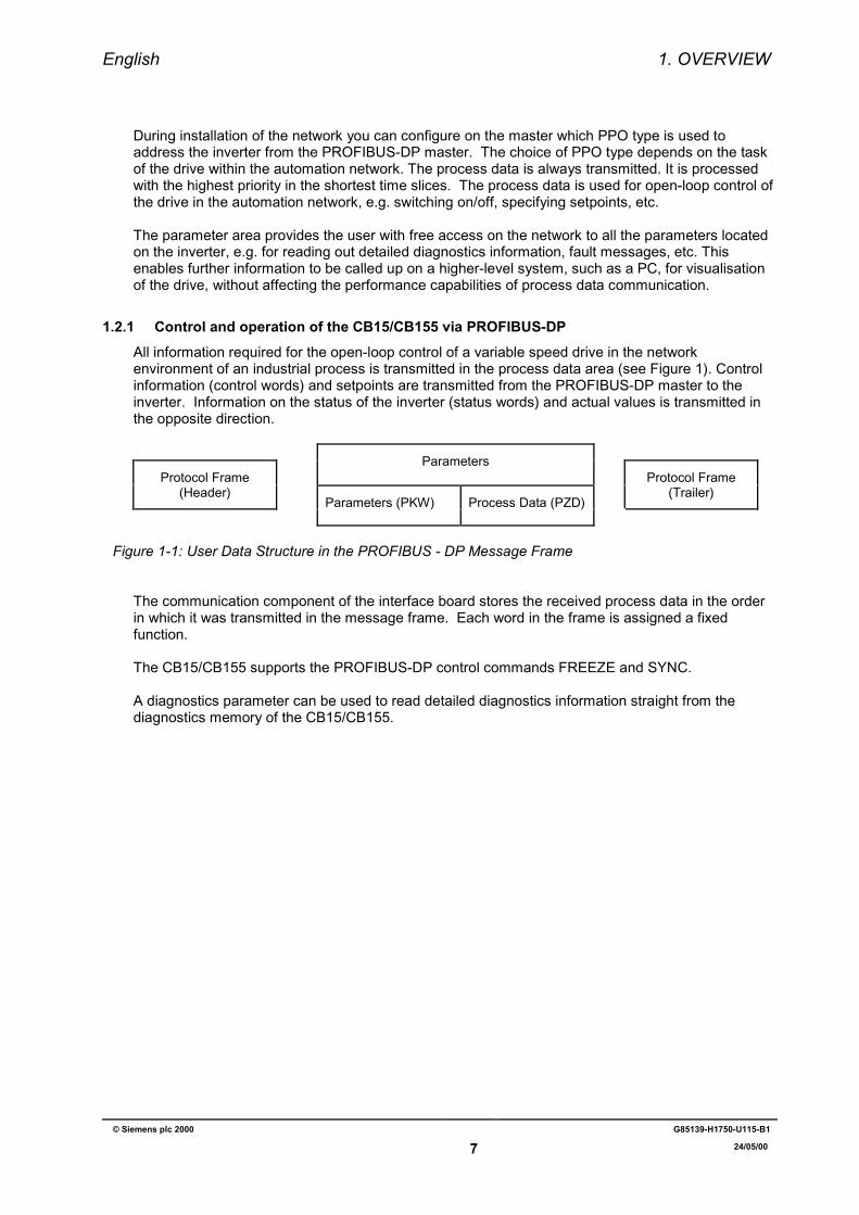
1.2.1 Control and operation of the CB15/CB155 via PROFIBUS-DPAll information required for the open-loop control of a variable speed drive in the networkenvironment of an industrial process is transmitted in the process data area (see Figure 1). Controlinformation (control words) and setpoints are transmitted from the PROFIBUS-DP master to theinverter. Information on the status of the inverter (status words) and actual values is transmitted inthe opposite direction.
ParametersProtocol Frame
(Header)Protocol Frame
(Trailer)Parameters (PKW) Process Data (PZD)
Figure 1-1: User Data Structure in the PROFIBUS - DP Message Frame
The communication component of the interface board stores the received process data in the orderin which it was transmitted in the message frame. Each word in the frame is assigned a fixedfunction.
The CB15/CB155 supports the PROFIBUS-DP control commands FREEZE and SYNC.
A diagnostics parameter can be used to read detailed diagnostics information straight from thediagnostics memory of the CB15/CB155.
English 2. INSTALLATION
© Siemens plc 2000 G85139-H1750-U115-B1
8 24/05/00
2 INSTALLATION
SECTION 2.1
2.1 CB15 Installation............................................................................................................................. 92.1.1 Installing the Module ............................................................................................................... 92.1.2 Connecting the Bus Cable....................................................................................................... 92.1.3 Bus Termination .................................................................................................................... 102.1.4 CB15-Front Panel.................................................................................................................. 10
SECTION 2.2
2.2 CB155 Installation (6SE9996 –0XA18) ........................................................................................ 112.2.1 Installing the Module ............................................................................................................. 112.2.2 Connecting the Bus Cable..................................................................................................... 122.2.3 Bus Termination .................................................................................................................... 13
SECTION 2.3
2.3 CB155 Installation (6SE9996 –0XA17) ........................................................................................ 142.3.1 Installing the Module ............................................................................................................. 142.3.2 Connecting the Bus Cable..................................................................................................... 152.3.3 Bus Termination .................................................................................................................... 16
CB15/CB155 COMMON INFORMATION
2.4 EMC Measures............................................................................................................................. 172.4.1 Equipotential Bonding ........................................................................................................... 172.4.2 Cable Installation................................................................................................................... 17
WARNINGIncorrect operation of the serial bus system can lead to an inverter beingswitched on inadvertently. Commissioning work must only be carried out bypersonnel who are qualified in installing such systems. Additionally, theguidelines associated with the installation of the inverter itself must be followed(see section 2 of the inverter’s handbook).
English 2.1. - CB15 INSTALLATION
© Siemens plc 2000 G85139-H1750-U115-B1
9 24/05/00
2.1 CB15 InstallationThe inverter must be switched off before the CB15 is either connected or disconnected. The CB15is powered directly from the inverter and therefore needs no additional external supply
2.1.1 Installing the ModuleFix the CB15 to the front of the inverter by mating the D-type connectors together and thensecuring in position by pressing the module onto the inverter.
2.1.2 Connecting the Bus Cable
2.1.2.1 CB15 TerminalsThe PROFIBUS connection must be made using the D-type socket on the front of the CB15.Connections to this socket are as follows:
Pin 3 PROFIBUS B connection (Red)Pin 8 PROFIBUS A connection (Green)
Additionally, the cable shield should be connected to the shell of the D-type connector, which isconnected to protective earth via the CB15 and inverter. The connector must be screwedsecurely to the CB15 to ensure both mechanical strength and earth continuity.
Connectors from the 6ES7972 range are recommended with Profibus cable 6XV 1830-OEH10
NoteAs the stations must be ‘ daisy-chained’ together (except for the stations at either end of thebus), there must be two cables into the D-type connector - one from the previous station andone to the next station.
This bus topology means that a station may be disconnected from the bus or powered downwhile still connected without affecting bus operation.
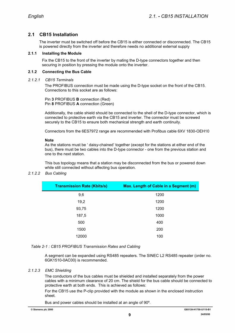
2.1.2.2 Bus Cabling
Transmission Rate (Kbits/s) Max. Length of Cable in a Segment (m)
9,6 1200
19,2 1200
93,75 1200
187,5 1000
500 400
1500 200
12000 100
Table 2-1 : CB15 PROFIBUS Transmission Rates and Cabling
A segment can be expanded using RS485 repeaters. The SINEC L2 RS485 repeater (order no.6GK1510-0AC00) is recommended.
2.1.2.3 EMC ShieldingThe conductors of the bus cables must be shielded and installed separately from the powercables with a minimum clearance of 20 cm. The shield for the bus cable should be connected toprotective earth at both ends. This is achieved as follows:For the CB15 use the P-clip provided with the module as shown in the enclosed instructionsheet.
Bus and power cables should be installed at an angle of 90º.
English 2.1. - CB15 INSTALLATION
© Siemens plc 2000 G85139-H1750-U115-B1
10 24/05/00
2.1.3 Bus TerminationFor interference-free operation of PROFIBUS-DP, the bus cable must be terminated at both endswith bus terminating resistors. The bus cable from the first PROFIBUS-DP station to the lastPROFIBUS-DP station should be treated as a single bus cable, so that the PROFIBUS-DPshould be terminated twice.For the CB15 this is achieved by moving the selector switch mounted on the D-type housing ofthe PROFIBUS-DP connector to the ON position.
Bus terminators must be switched to ON for the first station (e.g. the master) and the last station(slave). Note that the outgoing cable on 6ES7972 connectors is isolated when the bustermination is switched to ON, therefore the correct cable entry must be used on the first and lastconnectors (see information on the connector and its instruction leaflet).Note
(1) Ensure that you only connect/activate the bus terminator to the first network station and thelast network station.
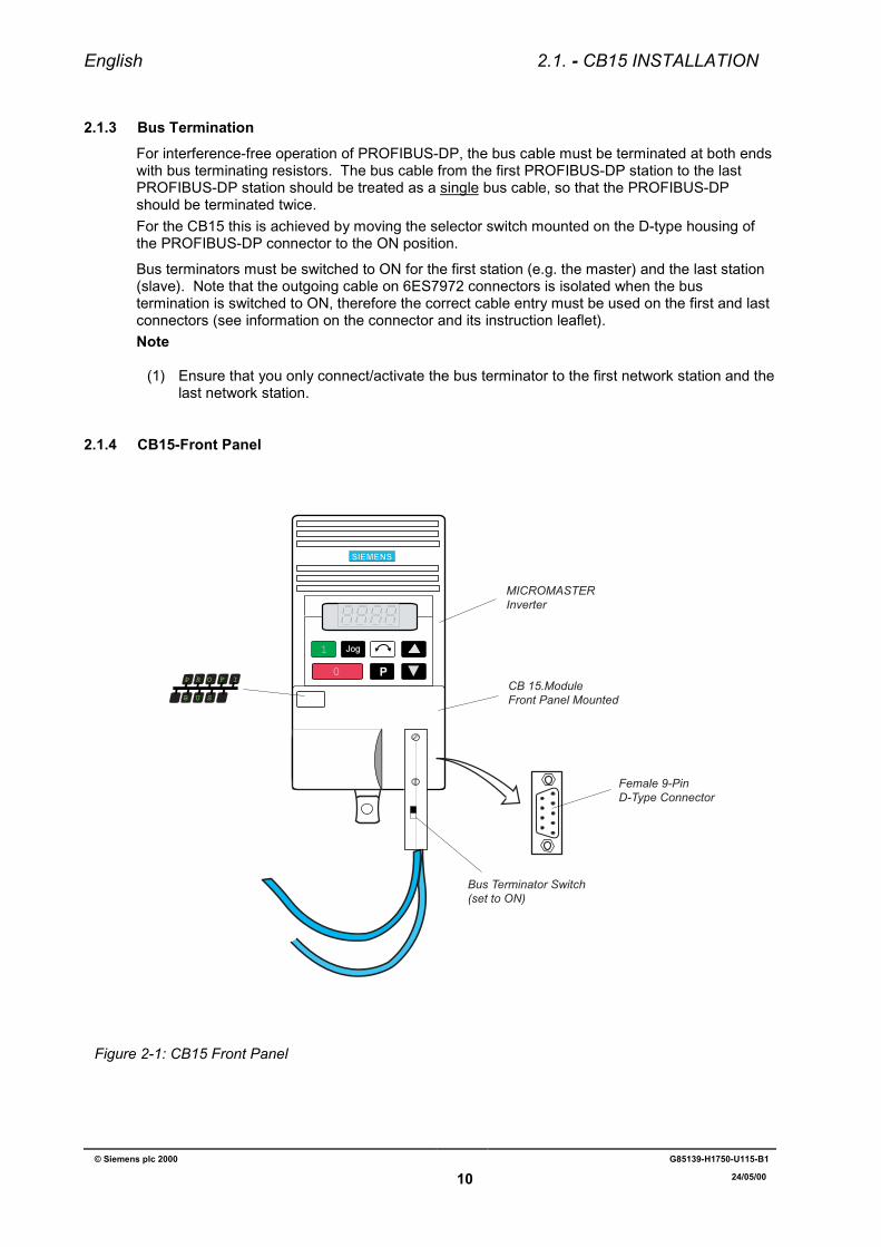
2.1.4 CB15-Front Panel
SIEMENS
1
0
Jog
P
MICROMASTERInverter
CB 15.Module Front Panel Mounted
Female 9-Pin D-Type Connector
P IFOR
B SU
Bus Terminator Switch(set to ON)
Figure 2-1: CB15 Front Panel
English 2.2.- CB155 INSTALLATION (6SE9996 –0XA18)
© Siemens plc 2000 G85139-H1750-U115-B1
11 24/05/00
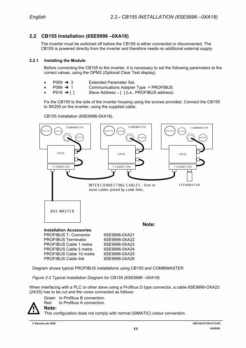
2.2 CB155 Installation (6SE9996 –0XA18)The inverter must be switched off before the CB155 is either connected or disconnected. TheCB155 is powered directly from the inverter and therefore needs no additional external supply
2.2.1 Installing the ModuleBefore connecting the CB155 to the inverter, it is necessary to set the following parameters to thecorrect values, using the OPM2 (Optional Clear Text display).
• P009 ➜ 3 Extended Parameter Set.• P099 ➜ 1 Communications Adapter Type = PROFIBUS• P918 ➜ [ ] Slave Address – [ ] (i.e., PROFIBUS address)
Fix the CB155 to the side of the inverter housing using the screws provided. Connect the CB155to SK200 on the inverter, using the supplied cable.
CB155 Installation (6SE9996-0XA18).
TERMINATOR
T CONNECTOR T CONNECTOR T CONNECTOR
CB155CB155 CB155
BUS MASTER
INTERCONNECTING CABLES - One or more cables joined by cable links.
COMBIMASTERCOMBIMASTERCOMBIMASTER
Installation AccessoriesPROFIBUS T- Connector 6SE9996-0XA21PROFIBUS Terminator 6SE9996-0XA22PROFIBUS Cable 1 metre 6SE9996-0XA23PROFIBUS Cable 5 metre 6SE9996-0XA24PROFIBUS Cable 10 metre 6SE9996-0XA25PROFIBUS Cable link 6SE9996-0XA26
Diagram shows typical PROFIBUS installations using CB155 and COMBIMASTER
Figure 2-2 Typical Installation Diagram for CB155 (6SE9996 –0XA18)
When interfacing with a PLC or other slave using a Profibus D type connector, a cable 6SE9996-OXA23(24/25) has to be cut and the cores connected as follows:
Green to Profibus B connection.Red to Profibus A connection.Note:This configuration does not comply with normal (SIMATIC) colour convention.
Note:.
English 2.2.- CB155 INSTALLATION (6SE9996 –0XA18)
© Siemens plc 2000 G85139-H1750-U115-B1
12 24/05/00
2.2.2 Connecting the Bus Cable
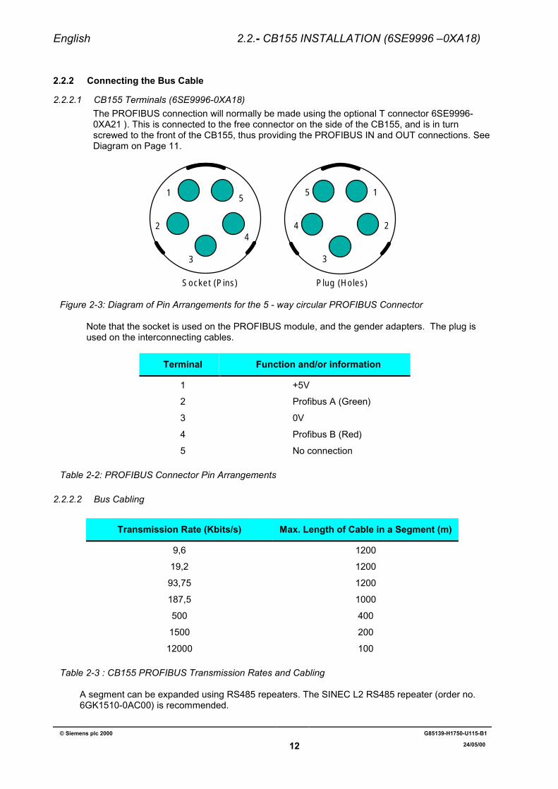
2.2.2.1 CB155 Terminals (6SE9996-0XA18)The PROFIBUS connection will normally be made using the optional T connector 6SE9996-0XA21 ). This is connected to the free connector on the side of the CB155, and is in turnscrewed to the front of the CB155, thus providing the PROFIBUS IN and OUT connections. SeeDiagram on Page 11.
1
2
3
4
51
2
3
4
5
Socket (Pins) Plug (Holes)
Figure 2-3: Diagram of Pin Arrangements for the 5 - way circular PROFIBUS Connector
Note that the socket is used on the PROFIBUS module, and the gender adapters. The plug isused on the interconnecting cables.
Terminal Function and/or information
1 +5V
2 Profibus A (Green)
3 0V
4 Profibus B (Red)
5 No connection
Table 2-2: PROFIBUS Connector Pin Arrangements
2.2.2.2 Bus Cabling
Transmission Rate (Kbits/s) Max. Length of Cable in a Segment (m)
9,6 1200
19,2 1200
93,75 1200
187,5 1000
500 400
1500 200
12000 100
Table 2-3 : CB155 PROFIBUS Transmission Rates and Cabling
A segment can be expanded using RS485 repeaters. The SINEC L2 RS485 repeater (order no.6GK1510-0AC00) is recommended.
English 2.2.- CB155 INSTALLATION (6SE9996 –0XA18)
© Siemens plc 2000 G85139-H1750-U115-B1
13 24/05/00
2.2.2.3 EMC ShieldingThe conductors of the bus cables must be shielded and installed separately from the powercables with a minimum clearance of 20 cm. The shield for the bus cable should be connected toprotective earth at both ends.For the CB155 (6SE9996 –0XA18) if the specified cables are used no further action isnecessary.
Bus and power cables should be installed at an angle of 90º.
2.2.3 Bus TerminationFor interference-free operation of PROFIBUS-DP, the bus cable must be terminated at both endswith bus terminating resistors. The bus cable from the first PROFIBUS-DP station to the lastPROFIBUS-DP station should be treated as a single bus cable, so that the PROFIBUS-DPshould be terminated twice.Bus terminators must be connected to the first station (e.g. the master) and the last station(slave).
For the CB155 (6SE9996 –0XA18) this is achieved by fitting the dedicated terminating connectorto the free position on the T connector at the end of the link.
Note(1) Ensure that you only connect/activate the bus terminator to the first network station and the
last network station.
English 2.3. - CB155 INSTALLATION (6SE9996 –0XA17)
© Siemens plc 2000 G85139-H1750-U115-B1
14 24/05/00
2.3 CB155 Installation (6SE9996 –0XA17)The inverter must be switched off before the CB155 is either connected or disconnected. TheCB155 is powered directly from the inverter and therefore needs no additional external supply
2.3.1 Installing the ModuleBefore connecting the CB155 to the inverter, it is necessary to set the following parameters to thecorrect values, using the OPM2 (Optional Clear Text display).
• P009 ➜ 3 Extended Parameter Set.• P099 ➜ 1 Communications Adapter Type = PROFIBUS• P918 ➜ [ ] Slave Address – [ ] (i.e., PROFIBUS address)
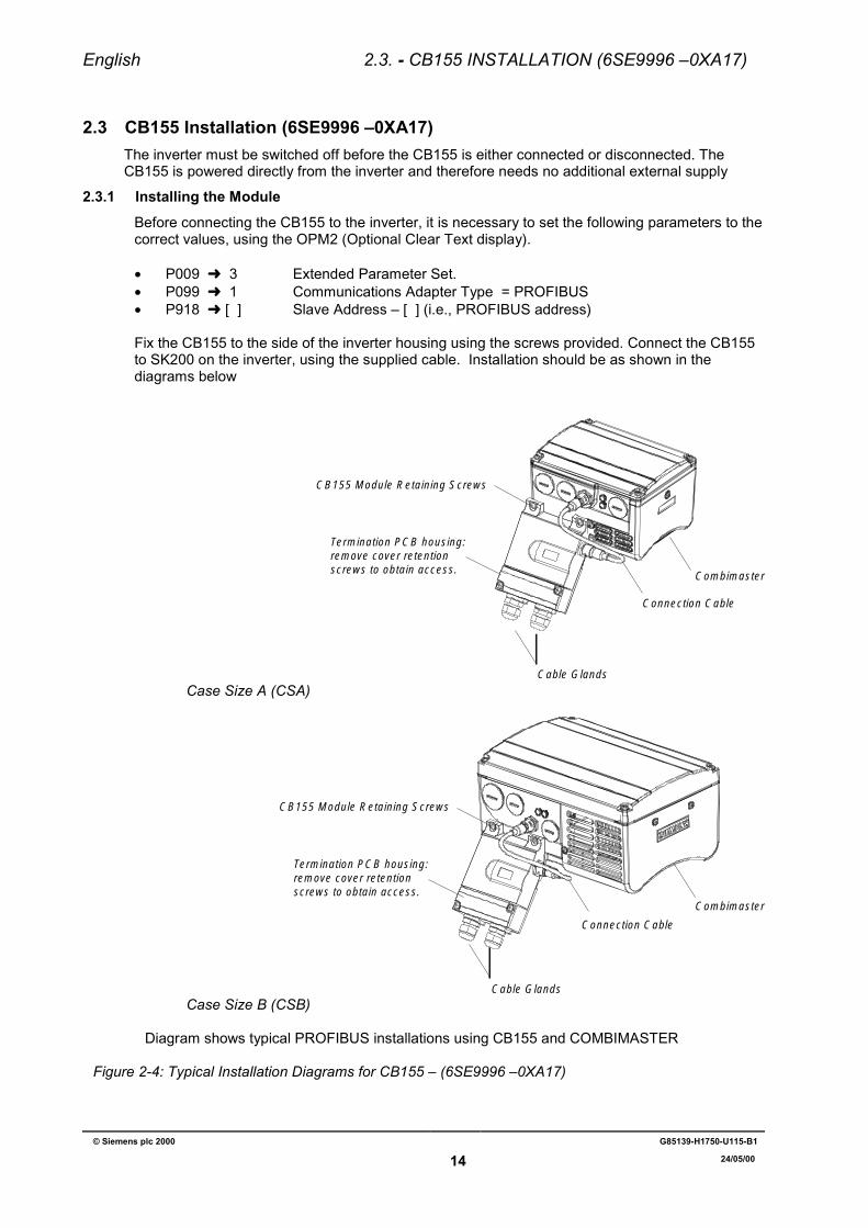
Fix the CB155 to the side of the inverter housing using the screws provided. Connect the CB155to SK200 on the inverter, using the supplied cable. Installation should be as shown in thediagrams below
Combimaster
Connection Cable
Cable Glands
CB155 Module Retaining Screws
Termination PCB housing:remove cover retention screws to obtain access.
Case Size A (CSA)
Combimaster
Connection Cable
Cable Glands
CB155 Module Retaining Screws
Termination PCB housing:remove cover retention screws to obtain access.
Case Size B (CSB)
Diagram shows typical PROFIBUS installations using CB155 and COMBIMASTER
Figure 2-4: Typical Installation Diagrams for CB155 – (6SE9996 –0XA17)
English 2.3. - CB155 INSTALLATION (6SE9996 –0XA17)
© Siemens plc 2000 G85139-H1750-U115-B1
15 24/05/00
2.3.2 Connecting the Bus Cable
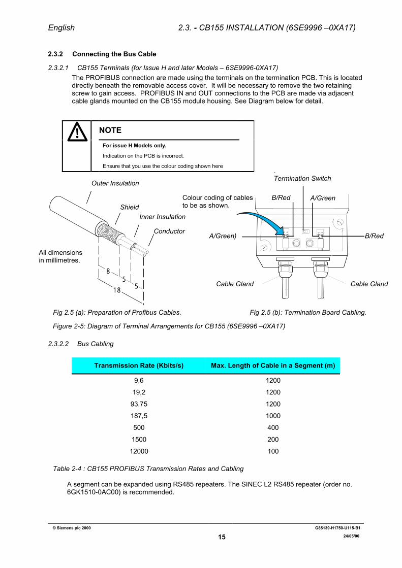
2.3.2.1 CB155 Terminals (for Issue H and later Models – 6SE9996-0XA17)The PROFIBUS connection are made using the terminals on the termination PCB. This is locateddirectly beneath the removable access cover. It will be necessary to remove the two retainingscrew to gain access. PROFIBUS IN and OUT connections to the PCB are made via adjacentcable glands mounted on the CB155 module housing. See Diagram below for detail.
NOTEFor issue H Models only.
Indication on the PCB is incorrect.
Ensure that you use the colour coding shown here
Figure 2-5: Diagram of Terminal Arrangements for CB155 (6SE9996 –0XA17)
2.3.2.2 Bus Cabling
Transmission Rate (Kbits/s) Max. Length of Cable in a Segment (m)
9,6 1200
19,2 1200
93,75 1200
187,5 1000
500 400
1500 200
12000 100
Table 2-4 : CB155 PROFIBUS Transmission Rates and Cabling
A segment can be expanded using RS485 repeaters. The SINEC L2 RS485 repeater (order no.6GK1510-0AC00) is recommended.
B/Red
B/Red
A/Green
A/Green)
Termination Switch
Colour coding of cablesto be as shown.
Cable Gland Cable Gland
85
518
Outer Insulation
Inner InsulationShield
Conductor
Fig 2.5 (a): Preparation of Profibus Cables. Fig 2.5 (b): Termination Board Cabling.
All dimensionsin millimetres.
English 2.3. - CB155 INSTALLATION (6SE9996 –0XA17)
© Siemens plc 2000 G85139-H1750-U115-B1
16 24/05/00
2.3.2.3 EMC ShieldingThe conductors of the bus cables must be shielded and installed separately from the powercables with a minimum clearance of 20 cm. The shield for the bus cable should be connected toprotective earth at both ends.For the CB155 (6SE9996 –0XA17) the P clip within the module connects the bus shield to theprotective earth.
Bus and power cables should be installed at an angle of 90º.
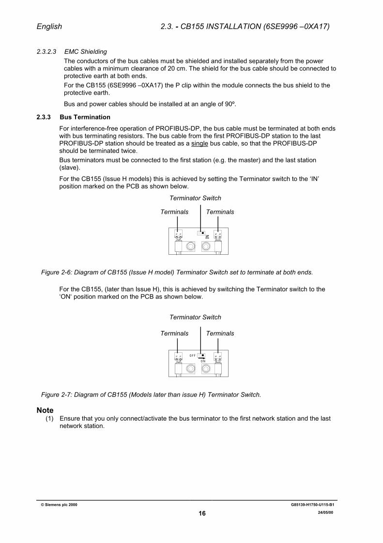
2.3.3 Bus TerminationFor interference-free operation of PROFIBUS-DP, the bus cable must be terminated at both endswith bus terminating resistors. The bus cable from the first PROFIBUS-DP station to the lastPROFIBUS-DP station should be treated as a single bus cable, so that the PROFIBUS-DPshould be terminated twice.Bus terminators must be connected to the first station (e.g. the master) and the last station(slave).
For the CB155 (Issue H models) this is achieved by setting the Terminator switch to the ‘IN’position marked on the PCB as shown below.
IN
Figure 2-6: Diagram of CB155 (Issue H model) Terminator Switch set to terminate at both ends.
For the CB155, (later than Issue H), this is achieved by switching the Terminator switch to the‘ON‘ position marked on the PCB as shown below.
OFF
ON
Figure 2-7: Diagram of CB155 (Models later than issue H) Terminator Switch.
Note(1) Ensure that you only connect/activate the bus terminator to the first network station and the last
network station.
Terminator Switch
TerminalsTerminals
Terminator Switch
Terminals Terminals

English 2.4. - CB15/CB155 INSTALLATION (common information)
© Siemens plc 2000 G85139-H1750-U115-B1
17 24/05/00
2.4 EMC MeasuresThe following measures are required for interference-free operation of the PROFIBUS-DP.Additional information on EMC precautions can be found in the ‘ET 200 Distributed I/O System’manual.
2.4.1 Equipotential BondingIf the cable shields are earthed at different sections of the system then equipotential bondingcables can be used to reduce current flow in the screen between the inverters and thePROFIBUS-DP master.
The following equipotential cables are recommended:16 mm2 Cu for equipotential bonding conductors up to 200m in length.25 mm2 Cu for equipotential bonding conductors over 200m in length.Use a large contact surface connection between the equipotential bonding conductors and theprotective ground conductor.
2.4.2 Cable Installation
Observe the following rules when installing cables:
-Bus cables (signal cables) may not be installed directly adjacent to power cables.
-Signal cables (and equipotential bonding cables) should be connected across the shortestpossible path.
-Power cables and signal cables must be installed in separate cable runs.
-Shields should have low impedance connections (large surface area).
English 3. OPERATING INFORMATION
© Siemens plc 2000 G85139-H1750-U115-B1
18 24/05/00
3 OPERATING INFORMATION3.1 Local Control
The inverter will operate a motor in an identical manner to that described in the operatinginstructions for the inverter.
3.2 Remote ControlDifferent modes of remote control are available via the serial link (refer to parameters P927 andP928 in section 3.3.2 below for details).
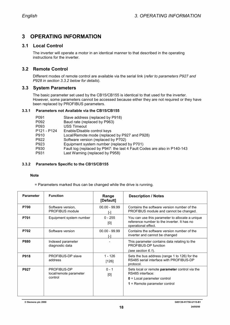
3.3 System ParametersThe basic parameter set used by the CB15/CB155 is identical to that used for the inverter.However, some parameters cannot be accessed because either they are not required or they havebeen replaced by PROFIBUS parameters.
3.3.1 Parameters not Available via the CB15/CB155P091 Slave address (replaced by P918)P092 Baud rate (replaced by P963)P093 USS TimeoutP121 - P124 Enable/Disable control keysP910 Local/Remote mode (replaced by P927 and P928)P922 Software version (replaced by P702)P923 Equipment system number (replaced by P701)P930 Fault log (replaced by P947: the last 4 Fault Codes are also in P140-143P931 Last Warning (replaced by P958)
3.3.2 Parameters Specific to the CB15/CB155
Note
== Parameters marked thus can be changed while the drive is running.
Parameter Function Range[Default]
Description / Notes
P700 Software version,PROFIBUS module
00.00 - 99.99[-]
Contains the software version number of thePROFIBUS module and cannot be changed.
P701 Equipment system number 0 - 255[0]
You can use this parameter to allocate a uniquereference number to the inverter. It has nooperational effect.
P702 Software version 00.00 - 99.99[-]
Contains the software version number of theinverter and cannot be changed
P880 Indexed parameterdiagnostic data
- This parameter contains data relating to thePROFIBUS-DP function(see section 6.1).
P918 PROFIBUS-DP slaveaddress
1 - 126[126]
Sets the bus address (range 1 to 126) for theRS485 serial interface with PROFIBUS-DPprotocol.
P927 PROFIBUS-DPlocal/remote parametercontrol
0 - 1[0]
Sets local or remote parameter control via theRS485 interface:0 = Local parameter control1 = Remote parameter control
English 3. OPERATING INFORMATION
© Siemens plc 2000 G85139-H1750-U115-B1
19 24/05/00
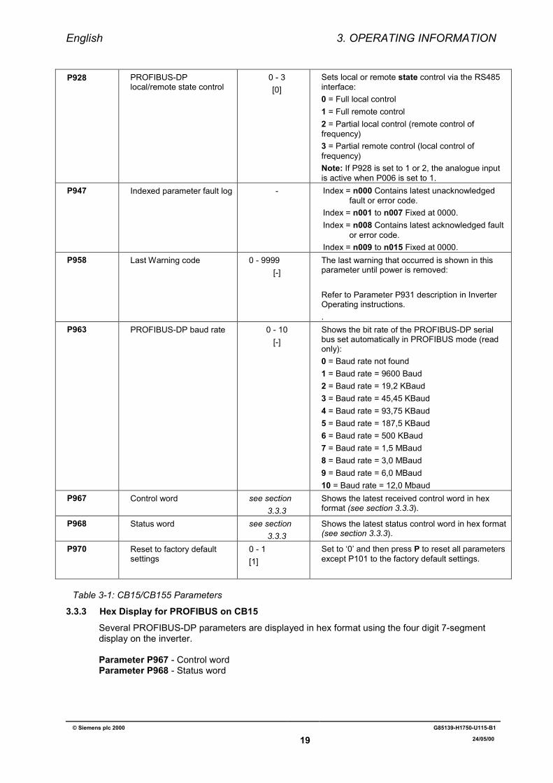
P928 PROFIBUS-DPlocal/remote state control
0 - 3[0]
Sets local or remote state control via the RS485interface:0 = Full local control1 = Full remote control2 = Partial local control (remote control offrequency)3 = Partial remote control (local control offrequency)Note: If P928 is set to 1 or 2, the analogue inputis active when P006 is set to 1.
P947 Indexed parameter fault log - Index = n000 Contains latest unacknowledgedfault or error code.
Index = n001 to n007 Fixed at 0000.Index = n008 Contains latest acknowledged fault
or error code.Index = n009 to n015 Fixed at 0000.
P958 Last Warning code 0 - 9999[-]
The last warning that occurred is shown in thisparameter until power is removed:
Refer to Parameter P931 description in InverterOperating instructions..
P963 PROFIBUS-DP baud rate 0 - 10[-]
Shows the bit rate of the PROFIBUS-DP serialbus set automatically in PROFIBUS mode (readonly):0 = Baud rate not found1 = Baud rate = 9600 Baud2 = Baud rate = 19,2 KBaud3 = Baud rate = 45,45 KBaud4 = Baud rate = 93,75 KBaud5 = Baud rate = 187,5 KBaud6 = Baud rate = 500 KBaud7 = Baud rate = 1,5 MBaud8 = Baud rate = 3,0 MBaud9 = Baud rate = 6,0 MBaud10 = Baud rate = 12,0 Mbaud
P967 Control word see section3.3.3
Shows the latest received control word in hexformat (see section 3.3.3).
P968 Status word see section3.3.3
Shows the latest status control word in hex format(see section 3.3.3).
P970 Reset to factory defaultsettings
0 - 1[1]
Set to ‘0’ and then press P to reset all parametersexcept P101 to the factory default settings.
Table 3-1: CB15/CB155 Parameters
3.3.3 Hex Display for PROFIBUS on CB15Several PROFIBUS-DP parameters are displayed in hex format using the four digit 7-segmentdisplay on the inverter.
Parameter P967 - Control wordParameter P968 - Status word
English 4. FAULT CODES
© Siemens plc 2000 G85139-H1750-U115-B1
20 24/05/00
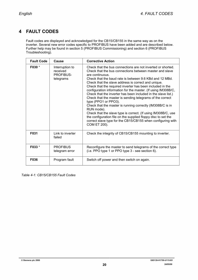
4 FAULT CODES
Fault codes are displayed and acknowledged for the CB15/CB155 in the same way as on theinverter. Several new error codes specific to PROFIBUS have been added and are described below.Further help may be found in section 5 (PROFIBUS Commissioning) and section 6 (PROFIBUSTroubleshooting).
Fault Code Cause Corrective Action
F030 * Interruption toreceivedPROFIBUS-telegrams
Check that the bus connections are not inverted or shorted.Check that the bus connections between master and slaveare continuous.Check that the baud rate is between 9.6 KBd and 12 MBd.Check that the slave address is correct and unique.Check that the required inverter has been included in theconfiguration information for the master. (If using IM308B/C,Check that the inverter has been included in the slave list.)Check that the master is sending telegrams of the correcttype (PPO1 or PPO3).Check that the master is running correctly (IM308B/C is inRUN mode).Check that the slave type is correct. (If using IM308B/C, usethe configuration file on the supplied floppy disc to set thecorrect slave type for the CB15/CB155 when configuring withCOM ET 200).
F031 Link to inverterfailed
Check the integrity of CB15/CB155 mounting to inverter.
F033 * PROFIBUStelegram error
Reconfigure the master to send telegrams of the correct type(i.e. PPO type 1 or PPO type 3 - see section 6).
F036 Program fault Switch off power and then switch on again.
Table 4-1: CB15/CB155 Fault Codes
English 5. COMMISSIONING
© Siemens plc 2000 G85139-H1750-U115-B1
21 24/05/00
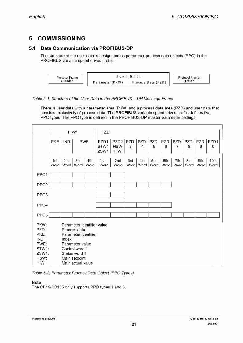
5 COMMISSIONING5.1 Data Communication via PROFIBUS-DP
The structure of the user data is designated as parameter process data objects (PPO) in thePROFIBUS variable speed drives profile:
U s e r D a t a
Parameter (PKW) Process Data (PZD)Protocol Frame
(Header)Protocol Frame
(Trailer)
Table 5-1: Structure of the User Data in the PROFIBUS - DP Message Frame
There is user data with a parameter area (PKW) and a process data area (PZD) and user data thatconsists exclusively of process data. The PROFIBUS variable speed drives profile defines fivePPO types. The PPO type is defined in the PROFIBUS-DP master parameter settings.
PKW PZD
PKE IND PWE PZD1STW1ZSW1
PZD2HSWHIW
PZD3
PZD4
PZD5
PZD6
PZD7
PZD8
PZD9
PZD10
1stWord
2ndWord
3rdWord
4thWord
1st Word
2ndWord
3rdWord
4thWord
5thWord
6thWord
7thWord
8thWord
9thWord
10thWord
PPO1
PPO2
PPO3
PPO4
PPO5
PKW:PZD:PKE:IND:PWE:STW1:ZSW1:HSW:HIW:
Parameter identifier valueProcess dataParameter identifierIndexParameter valueControl word 1Status word 1Main setpointMain actual value
Table 5-2: Parameter Process Data Object (PPO Types)
NoteThe CB15/CB155 only supports PPO types 1 and 3.
English 5. COMMISSIONING
© Siemens plc 2000 G85139-H1750-U115-B1
22 24/05/00
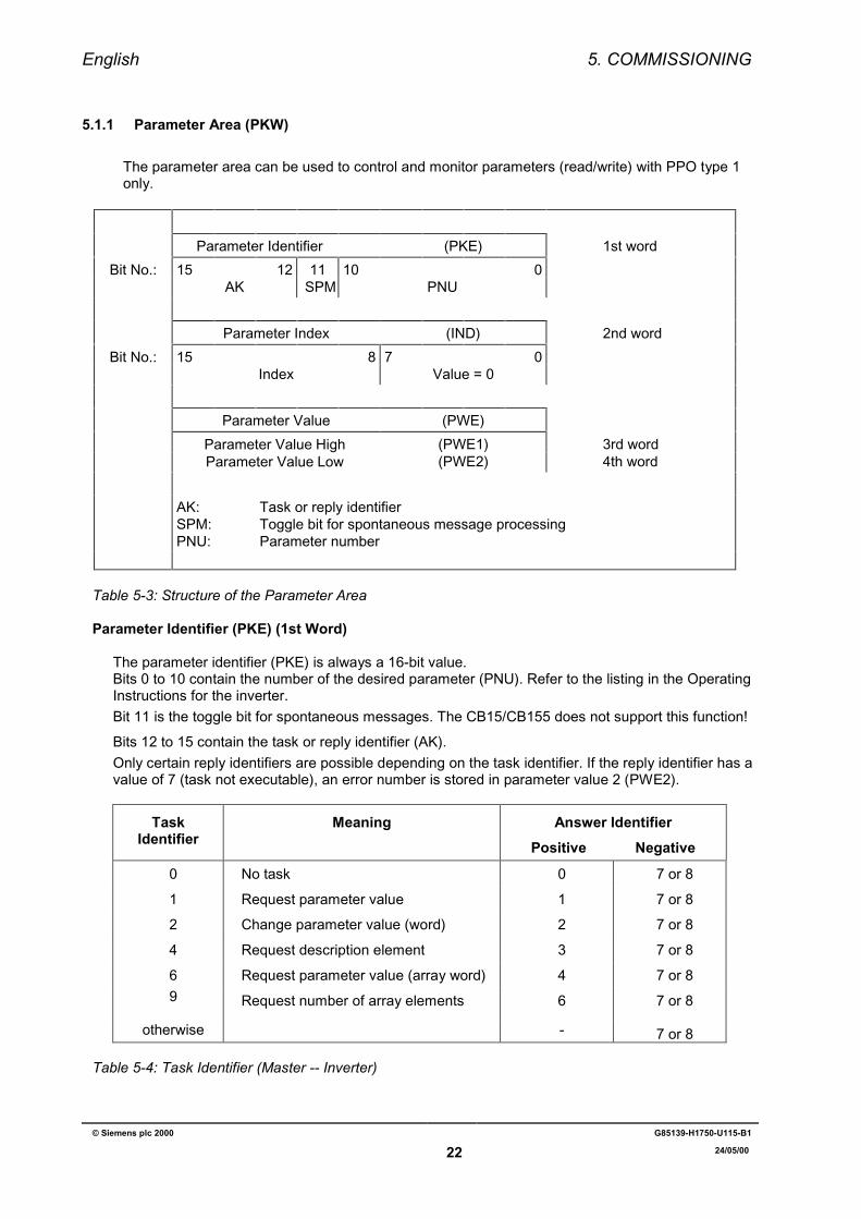
5.1.1 Parameter Area (PKW)
The parameter area can be used to control and monitor parameters (read/write) with PPO type 1only.
Parameter Identifier (PKE) 1st word
Bit No.: 15 12 11 10 0AK SPM PNU
Parameter Index (IND) 2nd word
Bit No.: 15 8 7 0Index Value = 0
Parameter Value (PWE)
Parameter Value High (PWE1) 3rd wordParameter Value Low (PWE2) 4th word
AK:SPM:PNU:
Task or reply identifierToggle bit for spontaneous message processingParameter number
Table 5-3: Structure of the Parameter Area
Parameter Identifier (PKE) (1st Word)
The parameter identifier (PKE) is always a 16-bit value.Bits 0 to 10 contain the number of the desired parameter (PNU). Refer to the listing in the OperatingInstructions for the inverter.Bit 11 is the toggle bit for spontaneous messages. The CB15/CB155 does not support this function!
Bits 12 to 15 contain the task or reply identifier (AK).Only certain reply identifiers are possible depending on the task identifier. If the reply identifier has avalue of 7 (task not executable), an error number is stored in parameter value 2 (PWE2).
TaskIdentifier
Meaning Answer IdentifierPositive Negative
0 No task 0 7 or 8
1 Request parameter value 1 7 or 8
2 Change parameter value (word) 2 7 or 8
4 Request description element 3 7 or 8
6 Request parameter value (array word) 4 7 or 89 Request number of array elements 6 7 or 8
otherwise - 7 or 8
Table 5-4: Task Identifier (Master -- Inverter)
English 5. COMMISSIONING
© Siemens plc 2000 G85139-H1750-U115-B1
23 24/05/00
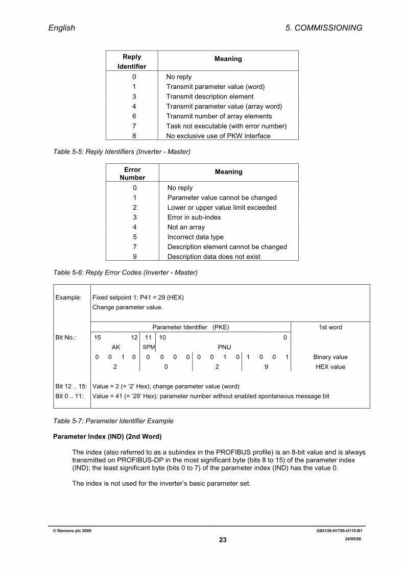
ReplyIdentifier
Meaning
0 No reply1 Transmit parameter value (word)3 Transmit description element4 Transmit parameter value (array word)6 Transmit number of array elements7 Task not executable (with error number)8 No exclusive use of PKW interface
Table 5-5: Reply Identifiers (Inverter - Master)
ErrorNumber
Meaning
0 No reply1 Parameter value cannot be changed2 Lower or upper value limit exceeded3 Error in sub-index4 Not an array5 Incorrect data type7 Description element cannot be changed9 Description data does not exist
Table 5-6: Reply Error Codes (Inverter - Master)
Example: Fixed setpoint 1: P41 = 29 (HEX)
Change parameter value.
Parameter Identifier (PKE) 1st word
Bit No.: 15 12 11 10 0
AK SPM PNU
0 0 1 0 0 0 0 0 0 0 1 0 1 0 0 1 Binary value
2 0 2 9 HEX value
Bit 12 .. 15: Value = 2 (= ‘2’ Hex); change parameter value (word)
Bit 0 .. 11: Value = 41 (= ‘29’ Hex); parameter number without enabled spontaneous message bit
Table 5-7: Parameter Identifier Example
Parameter Index (IND) (2nd Word)
The index (also referred to as a subindex in the PROFIBUS profile) is an 8-bit value and is alwaystransmitted on PROFIBUS-DP in the most significant byte (bits 8 to 15) of the parameter index(IND); the least significant byte (bits 0 to 7) of the parameter index (IND) has the value 0.
The index is not used for the inverter’s basic parameter set.
English 5. COMMISSIONING
© Siemens plc 2000 G85139-H1750-U115-B1
24 24/05/00
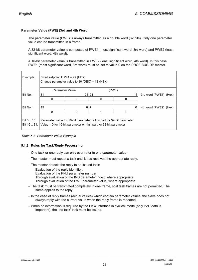
Parameter Value (PWE) (3rd and 4th Word)
The parameter value (PWE) is always transmitted as a double word (32 bits). Only one parametervalue can be transmitted in a frame.
A 32-bit parameter value is composed of PWE1 (most significant word, 3rd word) and PWE2 (leastsignificant word, 4th word).
A 16-bit parameter value is transmitted in PWE2 (least significant word, 4th word). In this casePWE1 (most significant word, 3rd word) must be set to value 0 on the PROFIBUS-DP master.
Example: Fixed setpoint 1: P41 = 29 (HEX)Change parameter value to 30 (DEC) = 1E (HEX)
Parameter Value (PWE)Bit No.: 31 24 23 16 3rd word (PWE1) (Hex)
0 0 0 0
Bit No.: 15 8 7 0 4th word (PWE2) (Hex)0 0 1 E
Bit 0 .. 15: Parameter value for 16-bit parameter or low part for 32-bit parameterBit 16 .. 31: Value = 0 for 16-bit parameter or high part for 32-bit parameter
Table 5-8: Parameter Value Example
5.1.2 Rules for Task/Reply Processing
−=One task or one reply can only ever refer to one parameter value.
−=The master must repeat a task until it has received the appropriate reply.
−=The master detects the reply to an issued task:Evaluation of the reply identifier.Evaluation of the PNU parameter number.Through evaluation of the IND parameter index, where appropriate.Through evaluation of the PWE parameter value, where appropriate.
−=The task must be transmitted completely in one frame, split task frames are not permitted. Thesame applies to the reply.
−=In the case of reply frames (actual values) which contain parameter values, the slave does notalways reply with the current value when the reply frame is repeated.
−=When no information is required by the PKW interface in cyclical mode (only PZD data isimportant), the ‘ no task’ task must be issued.
English 5. COMMISSIONING
© Siemens plc 2000 G85139-H1750-U115-B1
25 24/05/00
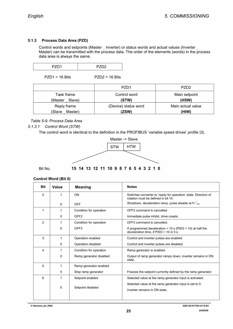
5.1.3 Process Data Area (PZD)Control words and setpoints (Master _ Inverter) or status words and actual values (Inverter _Master) can be transmitted with the process data. The order of the elements (words) in the processdata area is always the same.
PZD1 PZD2
PZD1 = 16 Bits PZD2 = 16 Bits
PZD1 PZD2
Task frame(Master _ Slave)
Control word(STW)
Main setpoint(HSW)
Reply frame(Slave _ Master)
(Device) status word(ZSW)
Main actual value(HIW)
Table 5-9: Process Data Area5.1.3.1 Control Word (STW)
The control word is identical to the definition in the PROFIBUS ‘variable speed drives’ profile |3|.
Bit No. 15 14 13 12 11 10 9 8 7 6 5 4 3 2 1 0
Control Word (Bit 0)
Bit Value Meaning Notes
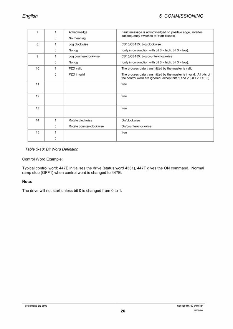
0 1
0
ON
OFF
Switches converter to ‘ready for operation’ state. Direction ofrotation must be defined in bit 14.Shutdown, deceleration ramp, pulse disable at f< fmin
1 1
0
Condition for operation
OFF2
OFF2 command is cancelled.
Immediate pulse inhibit, drive coasts.
2 1
0
Condition for operation
OFF3
OFF3 command is cancelled.
If programmed deceleration < 10 s (P003 < 10) at half thedeceleration time, if P003 > 10 in 5 s.
3 1
0
Operation enabled
Operation disabled
Control and inverter pulses are enabled.
Control and inverter pulses are disabled.
4 1
0
Condition for operation
Ramp generator disabled
Ramp generator is enabled.
Output of ramp generator ramps down, inverter remains in ONstate.
5 1
0
Ramp generator enabled
Stop ramp generator Freezes the setpoint currently defined by the ramp generator.
6 1
0
Setpoint enabled
Setpoint disabled
Selected value at the ramp generator input is activated.
Selected value at the ramp generator input is set to 0.
Inverter remains in ON state.
Master -> Slave
HTWSTW
English 5. COMMISSIONING
© Siemens plc 2000 G85139-H1750-U115-B1
26 24/05/00
7 1
0
Acknowledge
No meaning
Fault message is acknowledged on positive edge, invertersubsequently switches to ‘start disable’.
8 1
0
Jog clockwise
No jog
CB15/CB155: Jog clockwise
(only in conjunction with bit 0 = high. bit 3 = low).
9 1
0
Jog counter-clockwise
No jog
CB15/CB155: Jog counter-clockwise
(only in conjunction with bit 0 = high. bit 3 = low).
10 1
0
PZD valid
PZD invalid
The process data transmitted by the master is valid.
The process data transmitted by the master is invalid. All bits ofthe control word are ignored, except bits 1 and 2 (OFF2, OFF3)
11 free
12 free
13 free
14 1
0
Rotate clockwise
Rotate counter-clockwise
On/clockwise
On/counter-clockwise
15 1
0
free
Table 5-10: Bit Word Definition
Control Word Example:
Typical control word: 447E initialises the drive (status word 4331), 447F gives the ON command. Normalramp stop (OFF1) when control word is changed to 447E.
Note:
The drive will not start unless bit 0 is changed from 0 to 1.
English 5. COMMISSIONING
© Siemens plc 2000 G85139-H1750-U115-B1
27 24/05/00
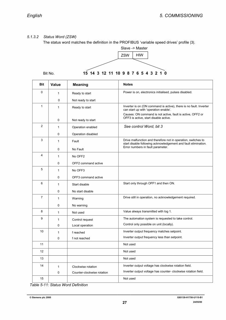
5.1.3.2 Status Word (ZSW)The status word matches the definition in the PROFIBUS ‘variable speed drives’ profile |3|.
Bit No. 15 14 3 12 11 10 9 8 7 6 5 4 3 2 1 0
Bit Value Meaning Notes
0 1
0
Ready to start
Not ready to start
Power is on, electronics initialised, pulses disabled.
1 1
0
Ready to start
Not ready to start
Inverter is on (ON command is active), there is no fault. Invertercan start up with ‘operation enable’.Causes: ON command is not active, fault is active, OFF2 orOFF3 is active, start disable active.
2 1
0
Operation enabled
Operation disabled
See control Word, bit 3
3 1
0
Fault
No Fault
Drive malfunction and therefore not in operation, switches tostart disable following acknowledgement and fault elimination.Error numbers in fault parameter.
4 1
0
No OFF2
OFF2 command active
5 1
0
No OFF3
OFF3 command active
6 1
0
Start disable
No start disable
Start only through OFF1 and then ON.
7 1
0
Warning
No warning
Drive still in operation, no acknowledgement required.
8 1 Not used Value always transmitted with log 1.
9 1
0
Control request
Local operation
The automation system is requested to take control.
Control only possible on unit (locally).
10 1
0
f reached
f not reached
Inverter output frequency matches setpoint.
Inverter output frequency less than setpoint.
11 Not used
12 Not used
13 Not used
14 1
0
Clockwise rotation
Counter-clockwise rotation
Inverter output voltage has clockwise rotation field.
Inverter output voltage has counter- clockwise rotation field.
15 Not used
Table 5-11: Status Word Definition
Slave -> Master
HIWZSW
English 5. COMMISSIONING
© Siemens plc 2000 G85139-H1750-U115-B1
28 24/05/00
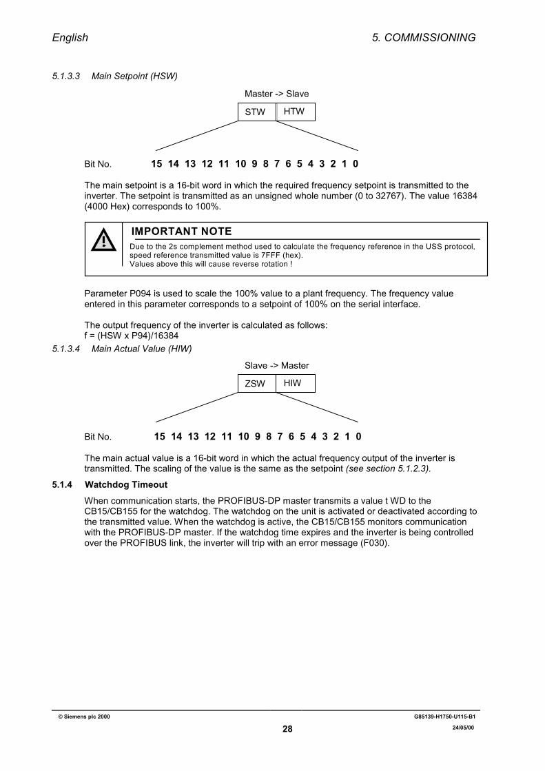
5.1.3.3 Main Setpoint (HSW)
Bit No. 15 14 13 12 11 10 9 8 7 6 5 4 3 2 1 0
The main setpoint is a 16-bit word in which the required frequency setpoint is transmitted to theinverter. The setpoint is transmitted as an unsigned whole number (0 to 32767). The value 16384(4000 Hex) corresponds to 100%.
Due to the 2s complement method used to calculate the frequency reference in the USS protocol,speed reference transmitted value is 7FFF (hex).Values above this will cause reverse rotation !
IMPORTANT NOTE
Parameter P094 is used to scale the 100% value to a plant frequency. The frequency valueentered in this parameter corresponds to a setpoint of 100% on the serial interface.
The output frequency of the inverter is calculated as follows:f = (HSW x P94)/16384
5.1.3.4 Main Actual Value (HIW)
Bit No. 15 14 13 12 11 10 9 8 7 6 5 4 3 2 1 0
The main actual value is a 16-bit word in which the actual frequency output of the inverter istransmitted. The scaling of the value is the same as the setpoint (see section 5.1.2.3).
5.1.4 Watchdog TimeoutWhen communication starts, the PROFIBUS-DP master transmits a value t WD to theCB15/CB155 for the watchdog. The watchdog on the unit is activated or deactivated according tothe transmitted value. When the watchdog is active, the CB15/CB155 monitors communicationwith the PROFIBUS-DP master. If the watchdog time expires and the inverter is being controlledover the PROFIBUS link, the inverter will trip with an error message (F030).
Master -> Slave
HTWSTW
Slave -> Master
HIWZSW
English 5. COMMISSIONING
© Siemens plc 2000 G85139-H1750-U115-B1
29 24/05/00
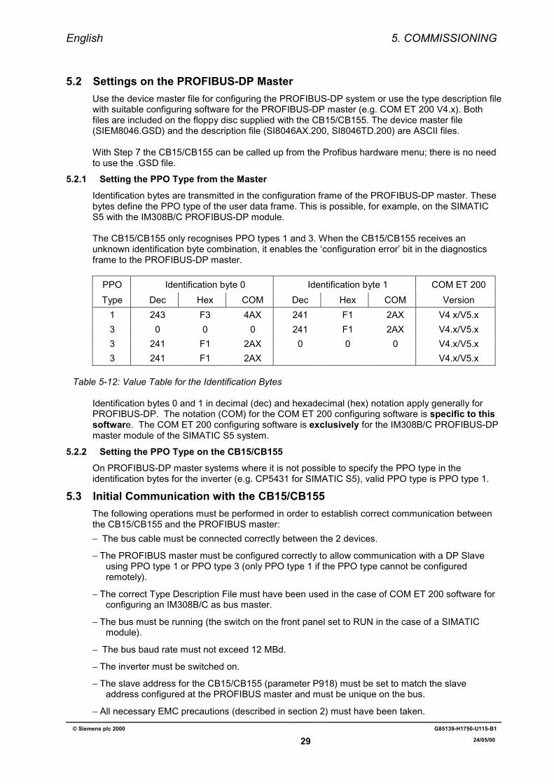
5.2 Settings on the PROFIBUS-DP MasterUse the device master file for configuring the PROFIBUS-DP system or use the type description filewith suitable configuring software for the PROFIBUS-DP master (e.g. COM ET 200 V4.x). Bothfiles are included on the floppy disc supplied with the CB15/CB155. The device master file(SIEM8046.GSD) and the description file (SI8046AX.200, SI8046TD.200) are ASCII files.
With Step 7 the CB15/CB155 can be called up from the Profibus hardware menu; there is no needto use the .GSD file.
5.2.1 Setting the PPO Type from the MasterIdentification bytes are transmitted in the configuration frame of the PROFIBUS-DP master. Thesebytes define the PPO type of the user data frame. This is possible, for example, on the SIMATICS5 with the IM308B/C PROFIBUS-DP module.
The CB15/CB155 only recognises PPO types 1 and 3. When the CB15/CB155 receives anunknown identification byte combination, it enables the ‘configuration error’ bit in the diagnosticsframe to the PROFIBUS-DP master.
PPO Identification byte 0 Identification byte 1 COM ET 200Type Dec Hex COM Dec Hex COM Version
1 243 F3 4AX 241 F1 2AX V4 x/V5.x3 0 0 0 241 F1 2AX V4.x/V5.x3 241 F1 2AX 0 0 0 V4.x/V5.x3 241 F1 2AX V4.x/V5.x
Table 5-12: Value Table for the Identification Bytes
Identification bytes 0 and 1 in decimal (dec) and hexadecimal (hex) notation apply generally forPROFIBUS-DP. The notation (COM) for the COM ET 200 configuring software is specific to thissoftware. The COM ET 200 configuring software is exclusively for the IM308B/C PROFIBUS-DPmaster module of the SIMATIC S5 system.
5.2.2 Setting the PPO Type on the CB15/CB155On PROFIBUS-DP master systems where it is not possible to specify the PPO type in theidentification bytes for the inverter (e.g. CP5431 for SIMATIC S5), valid PPO type is PPO type 1.
5.3 Initial Communication with the CB15/CB155The following operations must be performed in order to establish correct communication betweenthe CB15/CB155 and the PROFIBUS master:−==The bus cable must be connected correctly between the 2 devices.
−=The PROFIBUS master must be configured correctly to allow communication with a DP Slaveusing PPO type 1 or PPO type 3 (only PPO type 1 if the PPO type cannot be configuredremotely).
−=The correct Type Description File must have been used in the case of COM ET 200 software forconfiguring an IM308B/C as bus master.
−=The bus must be running (the switch on the front panel set to RUN in the case of a SIMATICmodule).
−==The bus baud rate must not exceed 12 MBd.
−=The inverter must be switched on.
−=The slave address for the CB15/CB155 (parameter P918) must be set to match the slaveaddress configured at the PROFIBUS master and must be unique on the bus.
−=All necessary EMC precautions (described in section 2) must have been taken.
English 6. PROFIBUS TROUBLESHOOTING
© Siemens plc 2000 G85139-H1750-U115-B1
30 24/05/00
6 PROFIBUS TROUBLESHOOTINGThe error messages, fault causes and remedial measures required are described in section 5. Ifcommunication over the PROFIBUS link is not successful, check the causes listed for fault codesF030 and F033.
6.1 Diagnostic ParametersThe CB15/CB155 stores diagnostics information in a diagnostics buffer for installation and servicepurposes. The diagnostics information can be read out with the indexed parameter P880.i(diagnostics).
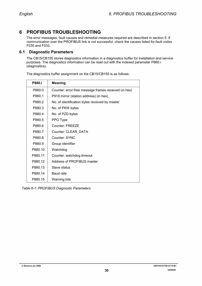
The diagnostics buffer assignment on the CB15/CB155 is as follows:
P880.i Meaning
P880.0 Counter: error-free message frames received (in hex)
P880.1 P918 mirror (station address) (in hex).
P880.2 No. of identification bytes received by master
P880.3 No. of PKW bytes
P880.4 No. of PZD bytes
P880.5 PPO Type
P880.6 Counter: FREEZE
P880.7 Counter: CLEAR_DATA
P880.8 Counter: SYNC
P880.9 Group identifier
P880.10 Watchdog
P880.11 Counter: watchdog timeout
P880.12 Address of PROFIBUS master
P880.13 Slave status
P880.14 Baud rate
P880.15 Warning bits
Table 6-1: PROFIBUS Diagnostic Parameters
English 6. PROFIBUS TROUBLESHOOTING
© Siemens plc 2000 G85139-H1750-U115-B1
31 24/05/00
Meaning of the CB15/CB155 diagnosis:P880.0 (Counter: error-free message frames received) Is incremented when a net data frame isreceived without an error.
P880.1 (P918 mirror)Station address entered.
P880.2 (No. of identification bytes)Must be 1 or 2 (or 25 when used with SIMATIC S5/S7), otherwise an F033 is triggered.
P880.3 (No. of PKW bytes)No. of PKW bytes detected. Must be 0 or 8, otherwise an F033 is triggered.
P880.4 (No. of PZD bytes)No. of PZD bytes detected. Must be 4, otherwise an F033 is triggered.
P880.5 (PPO type)Detected PPO type. Must be 1 or 3, otherwise an F033 is triggered.
P880.6 (Counter: FREEZE)Is incremented when a FREEZE frame is received.
P880.7 (Counter: CLEAR_DATA)Is incremented when a CLEAR_DATA frame is received.
P880.8 (Counter: SYNC)Is incremented when a SYNC frame is received.
P880.9 (Group identifier)The group identifier of the parameter telegram is entered.
P880.10 (Watchdog)The watchdog time of the parameter telegram is entered.
P880.11 (Counter: watchdog timeout)Is incremented when the watchdog time expires.
P880.12 (Address of PROFIBUS master)Address of the PROFIBUS master which has configured the CB15/CB155.
P880.13 (Slave status)Mirror of the software status:
1. Software not yet initialised.2. CB15/CB155 awaiting PROFIBUS parameterisation.3. CB15/CB155 awaiting PROFIBUS configuration.4. CB15/CB155 is in cycle mode.5. Watchdog timeout.
P880.14 (Baud rate)Only used for internal purposes. The detected baud rate is contained in parameter P963.
English 6. PROFIBUS TROUBLESHOOTING
© Siemens plc 2000 G85139-H1750-U115-B1
32 24/05/00
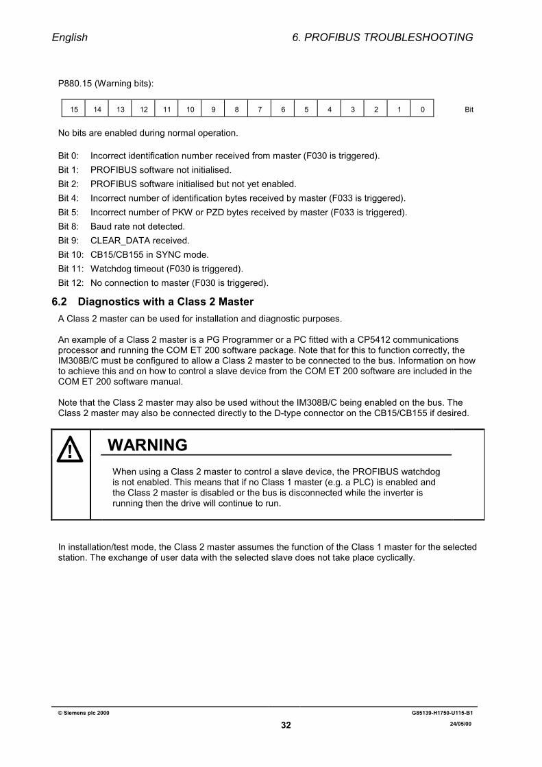
P880.15 (Warning bits):
15 14 13 12 11 10 9 8 7 6 5 4 3 2 1 0 Bit
No bits are enabled during normal operation.
Bit 0: Incorrect identification number received from master (F030 is triggered).Bit 1: PROFIBUS software not initialised.Bit 2: PROFIBUS software initialised but not yet enabled.Bit 4: Incorrect number of identification bytes received by master (F033 is triggered).Bit 5: Incorrect number of PKW or PZD bytes received by master (F033 is triggered).Bit 8: Baud rate not detected.Bit 9: CLEAR_DATA received.Bit 10: CB15/CB155 in SYNC mode.Bit 11: Watchdog timeout (F030 is triggered).Bit 12: No connection to master (F030 is triggered).
6.2 Diagnostics with a Class 2 MasterA Class 2 master can be used for installation and diagnostic purposes.
An example of a Class 2 master is a PG Programmer or a PC fitted with a CP5412 communicationsprocessor and running the COM ET 200 software package. Note that for this to function correctly, theIM308B/C must be configured to allow a Class 2 master to be connected to the bus. Information on howto achieve this and on how to control a slave device from the COM ET 200 software are included in theCOM ET 200 software manual.
Note that the Class 2 master may also be used without the IM308B/C being enabled on the bus. TheClass 2 master may also be connected directly to the D-type connector on the CB15/CB155 if desired.
WARNINGWhen using a Class 2 master to control a slave device, the PROFIBUS watchdogis not enabled. This means that if no Class 1 master (e.g. a PLC) is enabled andthe Class 2 master is disabled or the bus is disconnected while the inverter isrunning then the drive will continue to run.
In installation/test mode, the Class 2 master assumes the function of the Class 1 master for the selectedstation. The exchange of user data with the selected slave does not take place cyclically.