Embed Size (px)
Citation preview
Prof. Cherrice Traver EE/CS-152: Microprocessors and Microcontrollers
The 8051 Assembly Language

Prof. Cherrice Traver EE/CS-152: Microprocessors and Microcontrollers
Overview
• Data transfer instructions
• Addressing modes
• Data processing (arithmetic and logic)
• Program flow instructions
Prof. Cherrice Traver EE/CS-152: Microprocessors and Microcontrollers
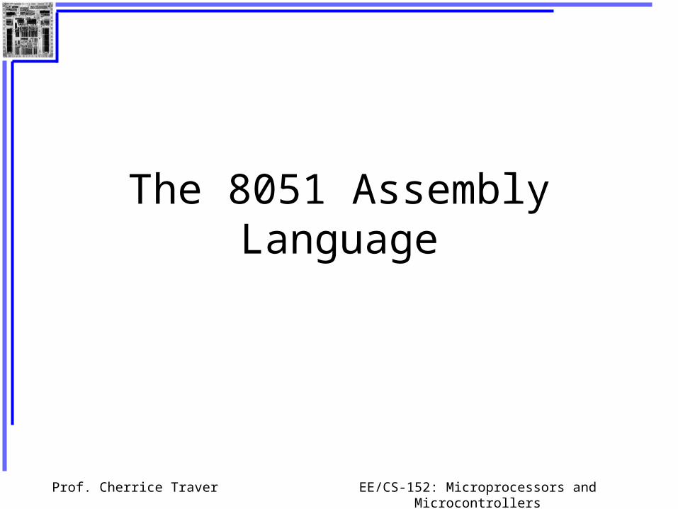
Data Transfer Instructions
MOV dest, source dest source
6 basic types:MOV a, byte ;move byte to accumulator
MOV byte, a ;move accumulator to byte
MOV Rn, byte ;move byte to register of
;current bank
MOV direct, byte ;move byte to internal RAM
MOV @Rn, byte ;move byte to internal RAM ;with address contained
in Rn
MOV DPTR, data16 ;move 16-bit data into data
;pointer
Prof. Cherrice Traver EE/CS-152: Microprocessors and Microcontrollers
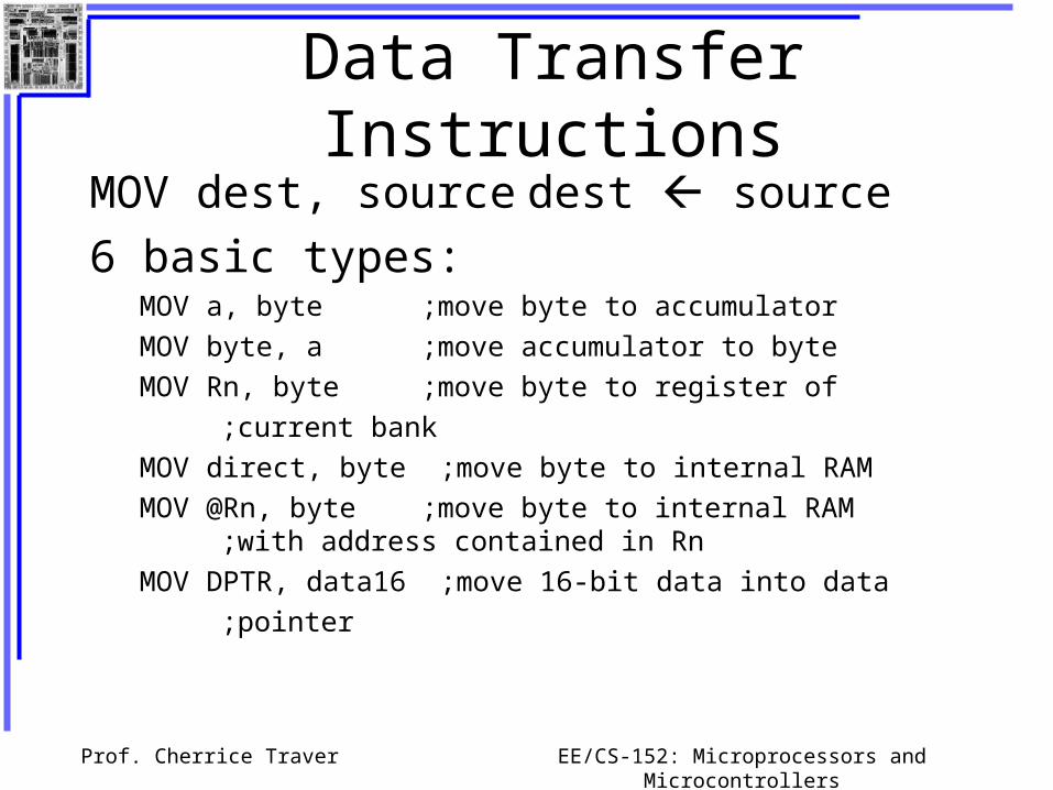
Other Data Transfer Instructions
• Stack instructionsPUSH byte ;increment stack pointer,
;move byte on stack
POP byte ;move from stack to byte, ;decrement stack pointer
• Exchange instructionsXCH a, byte ;exchange accumulator and
;byte
XCHD a, byte ;exchange low nibbles of ;accumulator and
byte

Prof. Cherrice Traver EE/CS-152: Microprocessors and Microcontrollers
Addressing Modes
Immediate Mode – specify data by its value
mov a, #0 ;put 0 in the accumulator
a = 00000000
mov a, #0x11 ; put 11hex in the accumulator
a = 00010001
mov a, #11 ; put 11 decimal in accumulator
a = 00001011
mov a, #77h ; put 77 hex in accumulator
a = 01110111

Prof. Cherrice Traver EE/CS-152: Microprocessors and Microcontrollers
Addressing ModesDirect Mode – specify data by its 8-bit address
mov a, 0x70 ; copy contents of RAM at 70h to a
mov 0xD0, a ; put contents of a into PSW

Prof. Cherrice Traver EE/CS-152: Microprocessors and Microcontrollers
Addressing Modes
Register Addressing – either source or destination is one of R0-R7
mov R0, a
mov a, R0

Prof. Cherrice Traver EE/CS-152: Microprocessors and Microcontrollers
Play with the Register Banks

Prof. Cherrice Traver EE/CS-152: Microprocessors and Microcontrollers
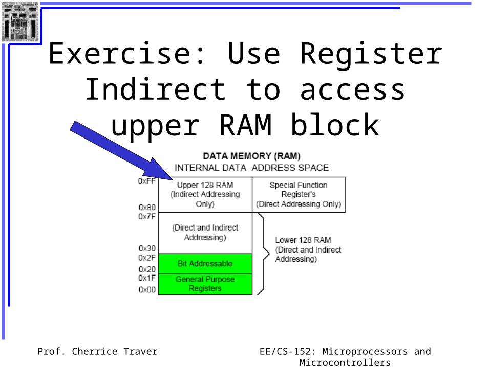
Addressing Modes
Register Indirect – the address of the source or destination is specified in registers
Uses registers R0 or R1 for 8-bit address:mov psw, #0 ; use register bank 0
mov r0, #0x3C
mov @r0, #3 ; memory at 3C gets #3
; M[3C] 3
Uses DPTR register for 16-bit addresses:mov dptr, #0x9000 ; dptr 9000h
mov a, @dptr ; a M[9000]
Note that 9000 is an address in external memory
Prof. Cherrice Traver EE/CS-152: Microprocessors and Microcontrollers
Exercise: Use Register Indirect to access upper RAM block

Prof. Cherrice Traver EE/CS-152: Microprocessors and Microcontrollers
Learn about Include Files

Prof. Cherrice Traver EE/CS-152: Microprocessors and Microcontrollers
Addressing Modes
• Register Indexed Mode – source or destination address is the sum of the base address and the accumulator.
• Base address can be DPTR or PCmov dptr, #4000h
mov a, #5
movc a, @a + dptr ;a M[4005]

Prof. Cherrice Traver EE/CS-152: Microprocessors and Microcontrollers
Addressing Modes
• Register Indexed Mode
• Base address can be DPTR or PCAddr cseg at 0x1000h
1000 mov a, #5
1002 movc a, @a + PC ;a M[1008]
1003 nopPC
Prof. Cherrice Traver EE/CS-152: Microprocessors and Microcontrollers
Table Lookup
Prof. Cherrice Traver EE/CS-152: Microprocessors and Microcontrollers
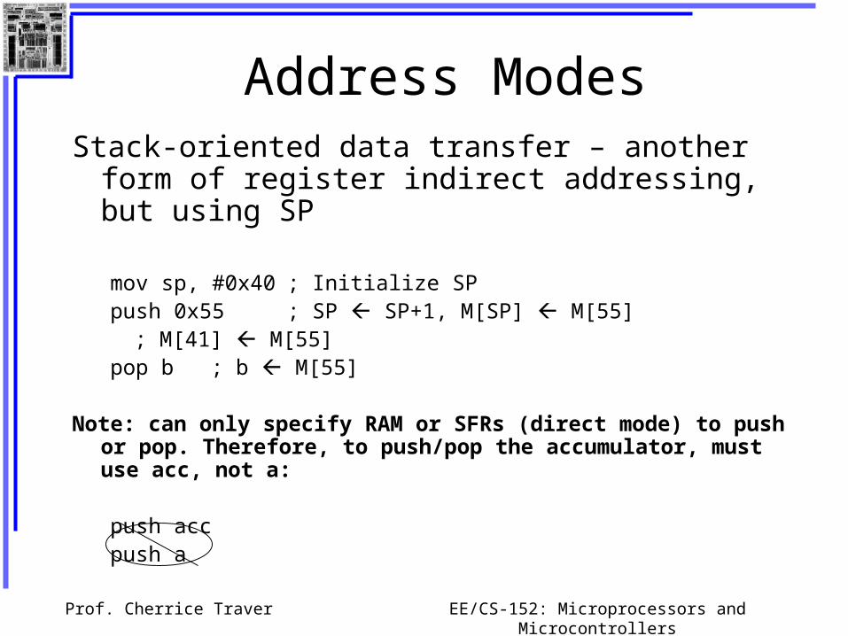
Address ModesStack-oriented data transfer – another form of register
indirect addressing, but using SP
mov sp, #0x40 ; Initialize SPpush 0x55 ; SP SP+1, M[SP] M[55]
; M[41] M[55]pop b ; b M[55]
Note: can only specify RAM or SFRs (direct mode) to push or pop. Therefore, to push/pop the accumulator, must use acc, not a:
push accpush a

Prof. Cherrice Traver EE/CS-152: Microprocessors and Microcontrollers
Stacks
pushpop
stack
stack pointer

Prof. Cherrice Traver EE/CS-152: Microprocessors and Microcontrollers
Address Modes
Exchange Instructions – two way data transferXCH a, 0x30 ; a M[30]
XCH a, R0 ; a R0
XCH a, @R0 ; a M[R0]
XCHD a, R0 ; exchange “digit”
R0[7..4] R0[3..0]a[7..4] a[3..0]
Prof. Cherrice Traver EE/CS-152: Microprocessors and Microcontrollers
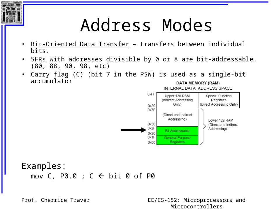
Address Modes• Bit-Oriented Data Transfer – transfers between individual bits.• SFRs with addresses divisible by 0 or 8 are bit-addressable. (80, 88, 90, 98, etc)• Carry flag (C) (bit 7 in the PSW) is used as a single-bit accumulator
Examples:mov C, P0.0 ; C bit 0 of P0

Prof. Cherrice Traver EE/CS-152: Microprocessors and Microcontrollers
Bit Addressable Memory20h – 2Fh (16 locations X 8-bits = 128 bits)
7F 78
1A
10
0F 08
07 06 05 04 03 02 01 00
27
26
25
24
23
22
21
20
2F
2E
2D
2C
2B
2A
29
28
Bit addressing:mov C, 1Ahormov C, 23h.2

Prof. Cherrice Traver EE/CS-152: Microprocessors and Microcontrollers
SPRs that are Bit AddressableSPRs with addresses of
multiples of 0 and 8 are bit addressable.
Notice that all 4 parallel I/O ports are bit addressable.
SFRs
Pink are implemented in
enhanced C8051F020
Address Register
0xF8 SPI0CN
0xF0 B
0xE8 ADC0CN
0xE0 ACC
0xD8 PCA0CN
0xD0 PSW
0xC8 T2CON
0xC0 SMB0CN
0xB8 IP
0xB0 P3
0xA8 IE
0xA0 P2
0x98 SCON
0x90 P1
0x88 TCON
0x80 P0

Prof. Cherrice Traver EE/CS-152: Microprocessors and Microcontrollers
Go Access the Port Bits….

Prof. Cherrice Traver EE/CS-152: Microprocessors and Microcontrollers
Part II
The 8051 Assembly Language

Prof. Cherrice Traver EE/CS-152: Microprocessors and Microcontrollers
Program Template
Use this template as a starting point for future programs.

Prof. Cherrice Traver EE/CS-152: Microprocessors and Microcontrollers
Data Processing Instructions
Arithmetic Instructions
Logic Instructions

Prof. Cherrice Traver EE/CS-152: Microprocessors and Microcontrollers
Arithmetic Instructions
• Add
• Subtract
• Increment
• Decrement
• Multiply
• Divide
• Decimal adjust

Prof. Cherrice Traver EE/CS-152: Microprocessors and Microcontrollers
Arithmetic Instructions
Mnemonic Description
ADD A, byte add A to byte, put result in A
ADDC A, byte add with carry
SUBB A, byte subtract with borrow
INC A increment A
INC byte increment byte in memory
INC DPTR increment data pointer
DEC A decrement accumulator
DEC byte decrement byte
MUL AB multiply accumulator by b register
DIV AB divide accumulator by b register
DA A decimal adjust the accumulator
Prof. Cherrice Traver EE/CS-152: Microprocessors and Microcontrollers
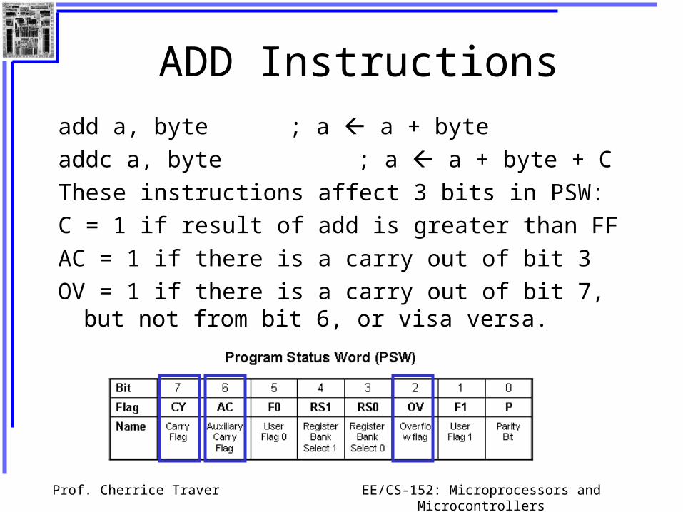
ADD Instructions
add a, byte ; a a + byte
addc a, byte ; a a + byte + C
These instructions affect 3 bits in PSW:
C = 1 if result of add is greater than FF
AC = 1 if there is a carry out of bit 3
OV = 1 if there is a carry out of bit 7, but not from bit 6, or visa versa.

Prof. Cherrice Traver EE/CS-152: Microprocessors and Microcontrollers
Instructions that Affect PSW bits
Prof. Cherrice Traver EE/CS-152: Microprocessors and Microcontrollers
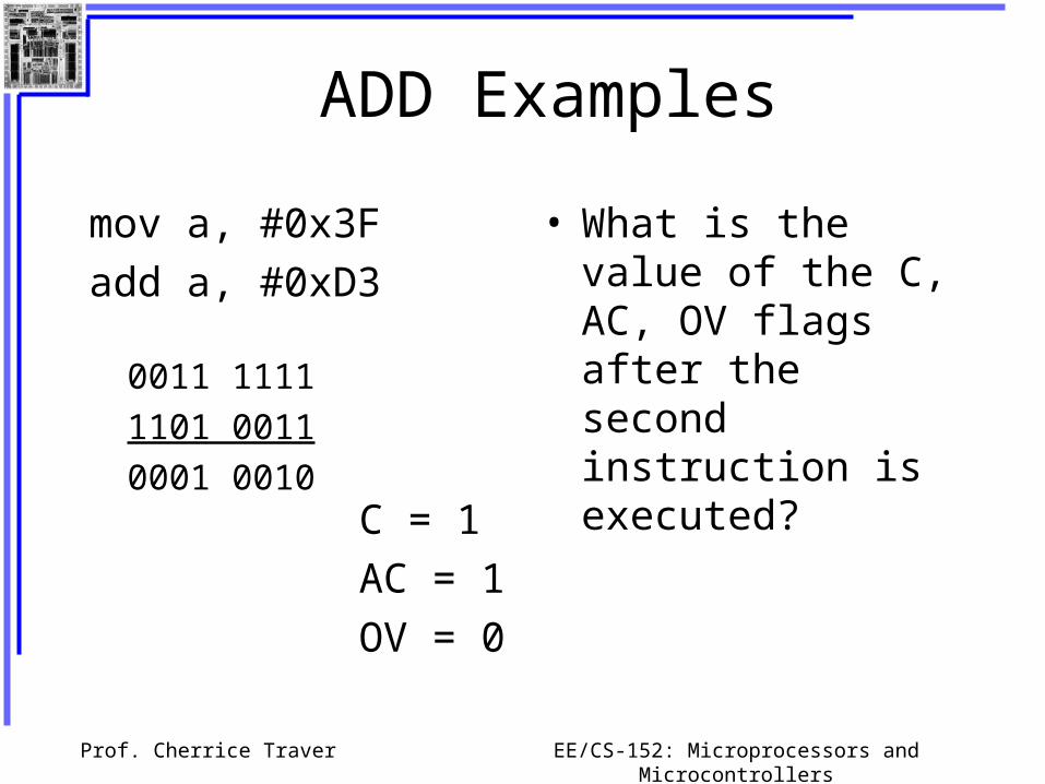
ADD Examples
mov a, #0x3F
add a, #0xD3
• What is the value of the C, AC, OV flags after the second instruction is executed?
0011 1111
1101 0011
0001 0010C = 1
AC = 1
OV = 0
Prof. Cherrice Traver EE/CS-152: Microprocessors and Microcontrollers
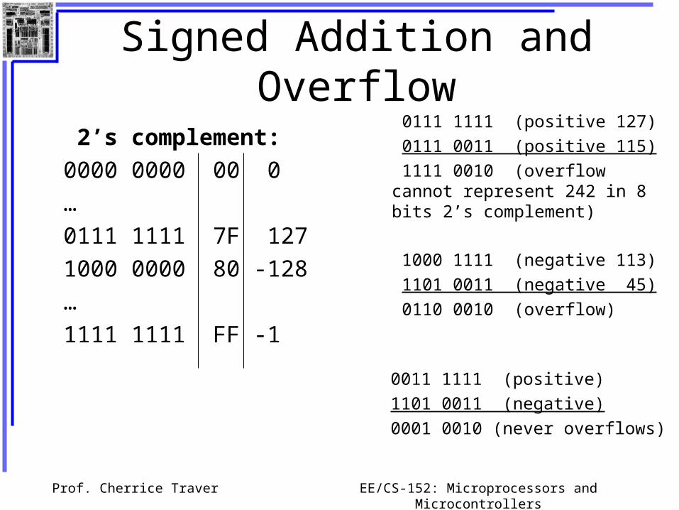
Signed Addition and Overflow 0111 1111 (positive 127)
0111 0011 (positive 115)
1111 0010 (overflow cannot represent 242 in 8 bits 2’s complement)
2’s complement:
0000 0000 00 0
…
0111 1111 7F 127
1000 0000 80 -128
…
1111 1111 FF -1
1000 1111 (negative 113)
1101 0011 (negative 45)
0110 0010 (overflow)
0011 1111 (positive)
1101 0011 (negative)
0001 0010 (never overflows)

Prof. Cherrice Traver EE/CS-152: Microprocessors and Microcontrollers
The ADD example…..
Prof. Cherrice Traver EE/CS-152: Microprocessors and Microcontrollers
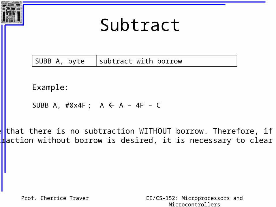
Subtract
SUBB A, byte subtract with borrow
Example:
SUBB A, #0x4F ; A A – 4F – C
Notice that there is no subtraction WITHOUT borrow. Therefore, ifa subtraction without borrow is desired, it is necessary to clear the Cflag.
Prof. Cherrice Traver EE/CS-152: Microprocessors and Microcontrollers
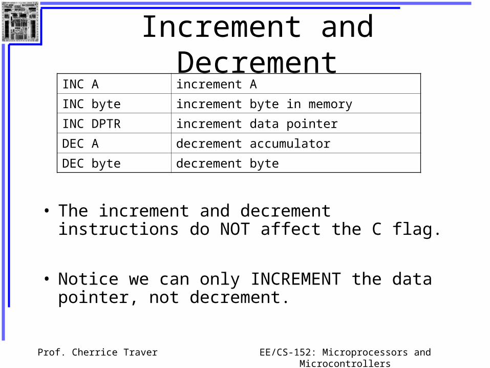
Increment and Decrement
• The increment and decrement instructions do NOT affect the C flag.
• Notice we can only INCREMENT the data pointer, not decrement.
INC A increment A
INC byte increment byte in memory
INC DPTR increment data pointer
DEC A decrement accumulator
DEC byte decrement byte
Prof. Cherrice Traver EE/CS-152: Microprocessors and Microcontrollers
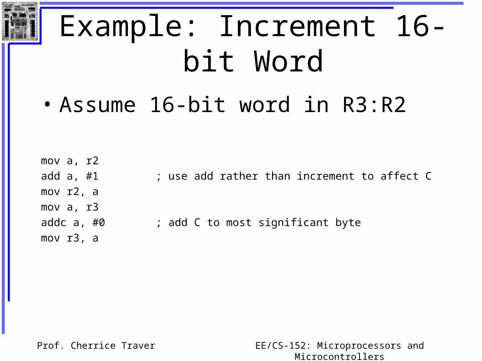
Example: Increment 16-bit Word
• Assume 16-bit word in R3:R2
mov a, r2 add a, #1 ; use add rather than increment to affect C mov r2, a mov a, r3 addc a, #0 ; add C to most significant bytemov r3, a
Prof. Cherrice Traver EE/CS-152: Microprocessors and Microcontrollers
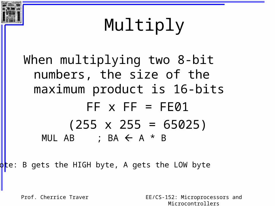
Multiply
When multiplying two 8-bit numbers, the size of the maximum product is 16-bits
FF x FF = FE01
(255 x 255 = 65025)
MUL AB ; BA A * B
Note: B gets the HIGH byte, A gets the LOW byte

Prof. Cherrice Traver EE/CS-152: Microprocessors and Microcontrollers
Go forth and multiply…

Prof. Cherrice Traver EE/CS-152: Microprocessors and Microcontrollers
Division
Integer Division
DIV AB ; divide A by B
A Quotient(A/B), B Remainder(A/B)
OV - used to indicate a divide by zero condition.C – set to zero

Prof. Cherrice Traver EE/CS-152: Microprocessors and Microcontrollers
Decimal Adjust
DA a ; decimal adjust a
Used to facilitate BCD addition. Adds “6” to either high or low nibble after an addition to create a valid BCD number.
Example:mov a, #0x23mov b, #0x29add a, b ; a 23 + 29 = 4C (wanted
52)
DA a ; a a + 6 = 52
Prof. Cherrice Traver EE/CS-152: Microprocessors and Microcontrollers
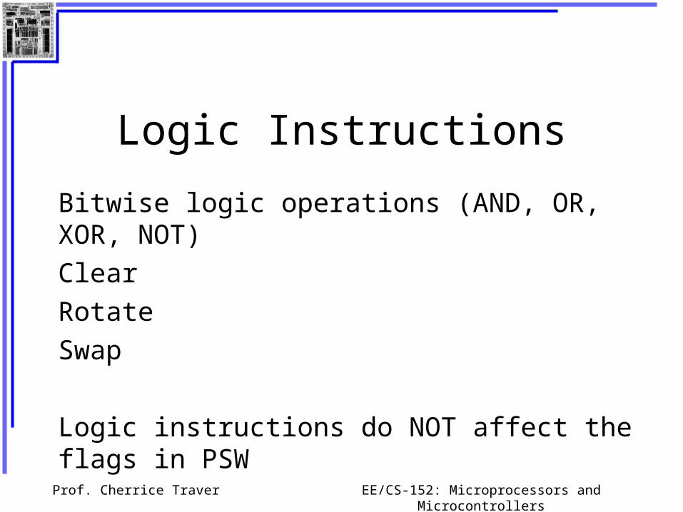
Logic Instructions
Bitwise logic operations (AND, OR, XOR, NOT)
Clear
Rotate
Swap
Logic instructions do NOT affect the flags in PSW

Prof. Cherrice Traver EE/CS-152: Microprocessors and Microcontrollers
Bitwise Logic
ANL – AND
ORL – OR
XRL – eXclusive OR
CPL – Complement
Examples:0000111110101100ANL
0000111110101100ORL
0000111110101100XRL
10101100CPL
00001100
10101111
10100011
01010011

Prof. Cherrice Traver EE/CS-152: Microprocessors and Microcontrollers
Address Modes with Logic
a, bytedirect, reg. indirect, reg, immediate
byte, adirect
byte, #constant
a ex: cpl a
ANL – AND
ORL – OR
XRL – eXclusive oR
CPL – Complement
Prof. Cherrice Traver EE/CS-152: Microprocessors and Microcontrollers
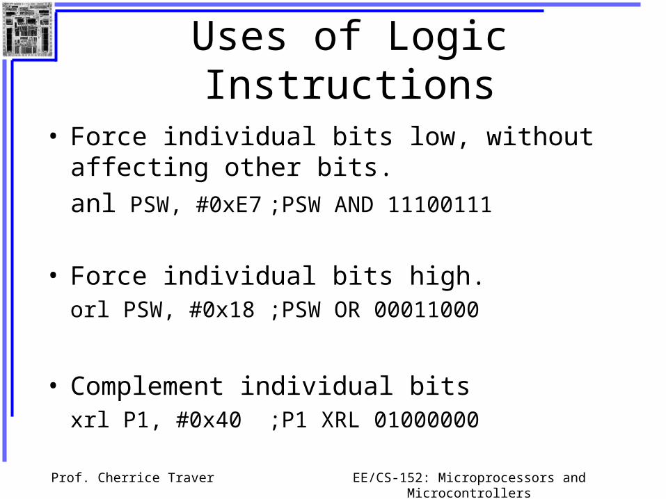
Uses of Logic Instructions
• Force individual bits low, without affecting other bits.
anl PSW, #0xE7 ;PSW AND 11100111
• Force individual bits high.orl PSW, #0x18 ;PSW OR 00011000
• Complement individual bitsxrl P1, #0x40 ;P1 XRL 01000000

Prof. Cherrice Traver EE/CS-152: Microprocessors and Microcontrollers
Other Logic Instructions
• CLR - clear
• RL – rotate left
• RLC – rotate left through Carry
• RR – rotate right
• RRC – rotate right through Carry
• SWAP – swap accumulator nibbles
Prof. Cherrice Traver EE/CS-152: Microprocessors and Microcontrollers
CLR – Set all bits to 0
CLR A
CLR byte (direct mode)
CLR Ri (register mode)
CLR @Ri (register indirect mode)

Prof. Cherrice Traver EE/CS-152: Microprocessors and Microcontrollers
Rotate
• Rotate instructions operate only on a
rl a
mov a, #0xF0 ; a 11110000
rl a ; a 11100001

Prof. Cherrice Traver EE/CS-152: Microprocessors and Microcontrollers
Rotate through Carry
rrc a
mov a, #0A9h ; a A9
add a, #14h ; a BD (10111101), C0
rrc a ; a 01011110, C1
C
Prof. Cherrice Traver EE/CS-152: Microprocessors and Microcontrollers
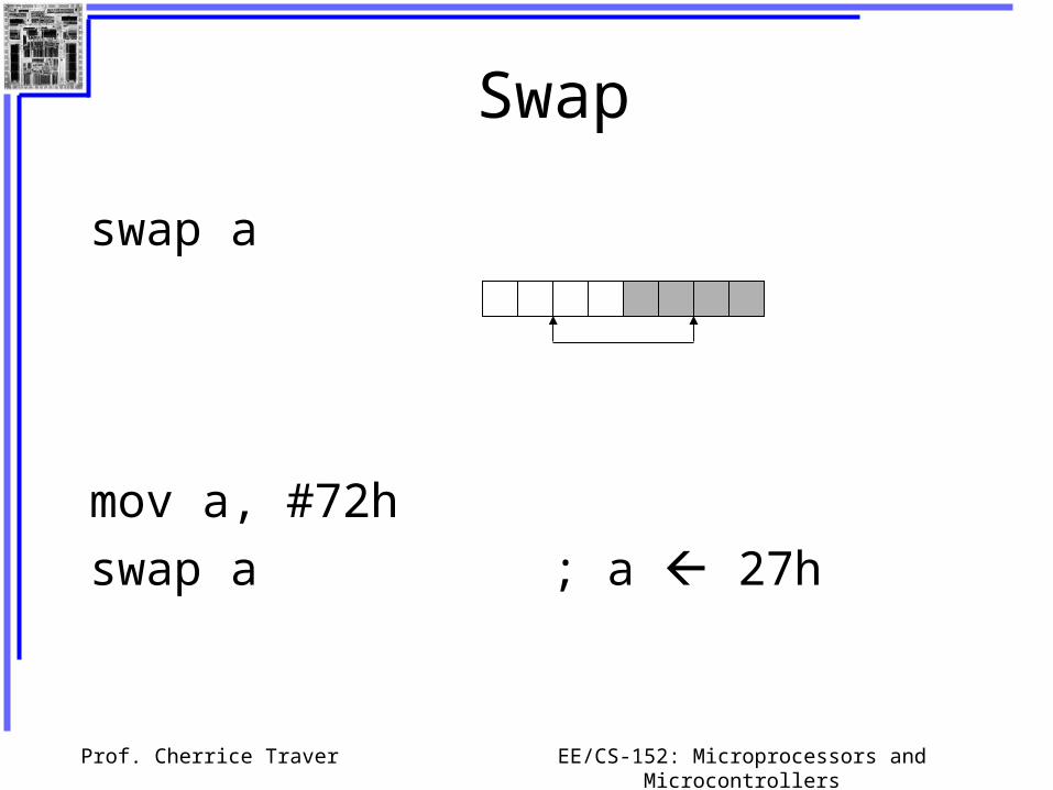
Swap
swap a
mov a, #72h
swap a ; a 27h

Prof. Cherrice Traver EE/CS-152: Microprocessors and Microcontrollers
Bit Logic Operations
Some logic operations can be used with single bit operands
ANL C, bit ANL C, /bitORL C, bit ORL C, /bitCLR CCLR bitCPL CCPL bitSETB CSETB bit
“bit” can be any of the bit-addressable RAMlocations or SFRs.
Prof. Cherrice Traver EE/CS-152: Microprocessors and Microcontrollers
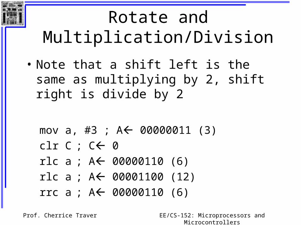
Rotate and Multiplication/Division
• Note that a shift left is the same as multiplying by 2, shift right is divide by 2
mov a, #3 ; A 00000011 (3)
clr C ; C 0
rlc a ; A 00000110 (6)
rlc a ; A 00001100 (12)
rrc a ; A 00000110 (6)

Prof. Cherrice Traver EE/CS-152: Microprocessors and Microcontrollers
Be Logical…..
Logical Operations Exercise

Prof. Cherrice Traver EE/CS-152: Microprocessors and Microcontrollers
Program Flow Control
• Unconditional jumps (“go to”)
• Conditional jumps
• Call and return

Prof. Cherrice Traver EE/CS-152: Microprocessors and Microcontrollers
Unconditional Jumps
• SJMP <rel addr> ; Short jump, relative address is 8-bit 2’s complement number, so jump can be up to 127 locations forward, or 128 locations back.
• LJMP <address 16> ; Long jump
• AJMP <address 11> ; Absolute jump to anywhere within 2K block of program memory
• JMP @A + DPTR ; Long indexed jump
Prof. Cherrice Traver EE/CS-152: Microprocessors and Microcontrollers
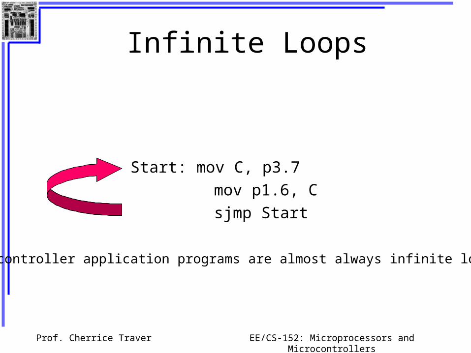
Infinite Loops
Start: mov C, p3.7
mov p1.6, C
sjmp Start
Microcontroller application programs are almost always infinite loops!
Prof. Cherrice Traver EE/CS-152: Microprocessors and Microcontrollers
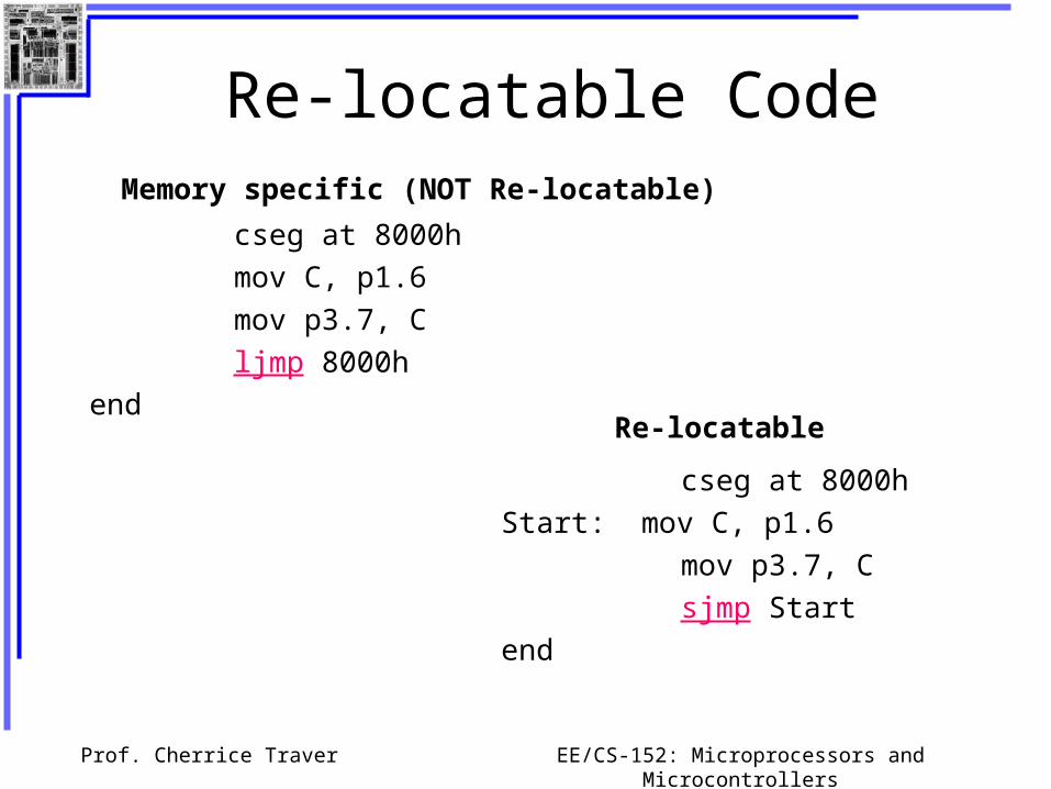
Re-locatable Code
cseg at 8000h
mov C, p1.6
mov p3.7, C
ljmp 8000h
end
cseg at 8000h
Start: mov C, p1.6
mov p3.7, C
sjmp Start
end
Re-locatable
Memory specific (NOT Re-locatable)

Prof. Cherrice Traver EE/CS-152: Microprocessors and Microcontrollers
Conditional Jumps
These instructions cause a jump to occur only if a condition is true. Otherwise, program execution continues with the next instruction.
loop: mov a, P1
jz loop ; if a=0, goto loop, ;else goto next
;instruction
mov b, a

Prof. Cherrice Traver EE/CS-152: Microprocessors and Microcontrollers
Conditional jumpsMnemonic Description
JZ <rel addr> Jump if a = 0JNZ <rel addr> Jump if a != 0JC <rel addr> Jump if C = 1JNC <rel addr> Jump if C != 1JB <bit>, <rel addr> Jump if bit = 1JNB <bit>,<rel addr> Jump if bit != 1JBC <bir>, <rel addr> Jump if bit =1, clear bitCJNE A, direct, <rel addr>
Compare A and memory, jump if not equal

Prof. Cherrice Traver EE/CS-152: Microprocessors and Microcontrollers
Conditional Jumps for Branchingif condition is true
goto label
else
goto next instruction
jz led_offsetb Cmov P1.6, Csjmp skipoverclr Cmov P1.6, Cmov A, P0
led_off:
skipover:
if a = 0 is truesend a 0 to LED
else
send a 1 to LED
condition
true
false
label

Prof. Cherrice Traver EE/CS-152: Microprocessors and Microcontrollers
More Conditional JumpsMnemonic Description
CJNE A, #data <rel addr> Compare A and data, jump if not equal
CJNE Rn, #data <rel addr> Compare Rn and data, jump if not equal
CJNE @Rn, #data <rel addr> Compare Rn and memory, jump if not equal
DJNZ Rn, <rel addr> Decrement Rn and then jump if not zero
DJNZ direct, <rel addr> Decrement memory and then jump if not zero
Prof. Cherrice Traver EE/CS-152: Microprocessors and Microcontrollers
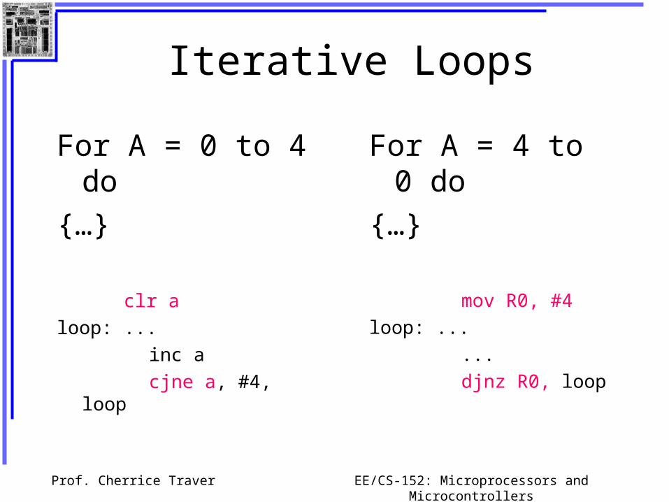
Iterative Loops
For A = 0 to 4 do
{…}
clr a
loop: ...
inc a
cjne a, #4, loop
For A = 4 to 0 do
{…}
mov R0, #4
loop: ...
...
djnz R0, loop

Prof. Cherrice Traver EE/CS-152: Microprocessors and Microcontrollers
Branch and Jump
Fun with the LED
Prof. Cherrice Traver EE/CS-152: Microprocessors and Microcontrollers
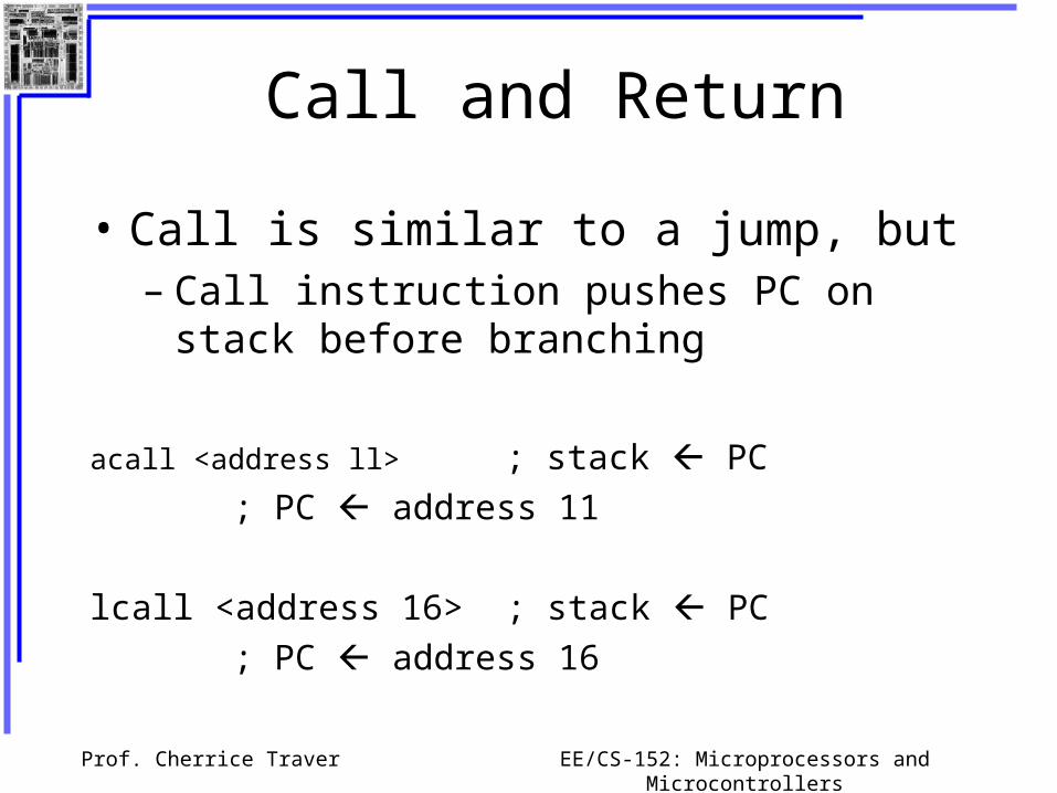
Call and Return
• Call is similar to a jump, but– Call instruction pushes PC on stack before
branching
acall <address ll> ; stack PC
; PC address 11
lcall <address 16> ; stack PC
; PC address 16

Prof. Cherrice Traver EE/CS-152: Microprocessors and Microcontrollers
Return
• Return is also similar to a jump, but– Return instruction pops PC from stack to get
address to jump to
ret ; PC stack

Prof. Cherrice Traver EE/CS-152: Microprocessors and Microcontrollers
Subroutines
Main: ...
acall sublabel
...
...
sublabel:...
...
ret
the subroutine
call to the subroutine

Prof. Cherrice Traver EE/CS-152: Microprocessors and Microcontrollers
Initializing Stack Pointer
• The Stack Pointer (SP) is initialized to 0x07. (Same address as R7)
• When using subroutines, the stack will be used to store the PC, so it is very important to initialize the stack pointer. Location 2F is often used.
mov SP, #0x2F
Prof. Cherrice Traver EE/CS-152: Microprocessors and Microcontrollers
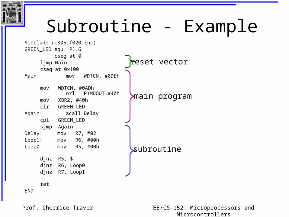
Subroutine - Example$include (c8051f020.inc) GREEN_LED equ P1.6 cseg at 0 ljmp Main
cseg at 0x100 Main: mov WDTCN, #0DEh
mov WDTCN, #0ADh
orl P1MDOUT,#40h mov XBR2, #40h clr GREEN_LED
Again: acall Delay cpl GREEN_LED sjmp Again
Delay: mov R7, #02Loop1: mov R6, #00hLoop0: mov R5, #00h
djnz R5, $
djnz R6, Loop0
djnz R7, Loop1
ret
END
reset vector
main program
subroutine

Prof. Cherrice Traver EE/CS-152: Microprocessors and Microcontrollers
Subroutine – another example; Program to compute square root of value on Port 3 (bits 3-0) and
; output on Port 1.
$INCLUDE (C8051F020.inc)
cseg at 0
ljmp Main
Main: mov P3MDOUT, #0 ; Set open-drain mode
mov P3, #0xFF ; Port 3 is an input
mov P1MDOUT, #0xFF ; Port 1 is an output
mov XBR2, #40h ; Enable crossbar
loop: mov a, P3
anl a, #0x0F ; Clear bits 7..4 of A
lcall sqrt
mov P1, a
sjmp loop
sqrt: inc a
movc a, @a + PC
ret
squares: db 0,1,1,1,2,2,2,2,2,3,3,3,3,3,3,3
end
reset vector
main program
subroutine
data
Prof. Cherrice Traver EE/CS-152: Microprocessors and Microcontrollers
Why Subroutines?
• Subroutines allow us to have "structured" assembly language programs.
• This is useful for breaking a large design into manageable parts.
• It saves code space when subroutines can be called many times in the same program.
Prof. Cherrice Traver EE/CS-152: Microprocessors and Microcontrollers
Timeout for Subroutines....
Prof. Cherrice Traver EE/CS-152: Microprocessors and Microcontrollers
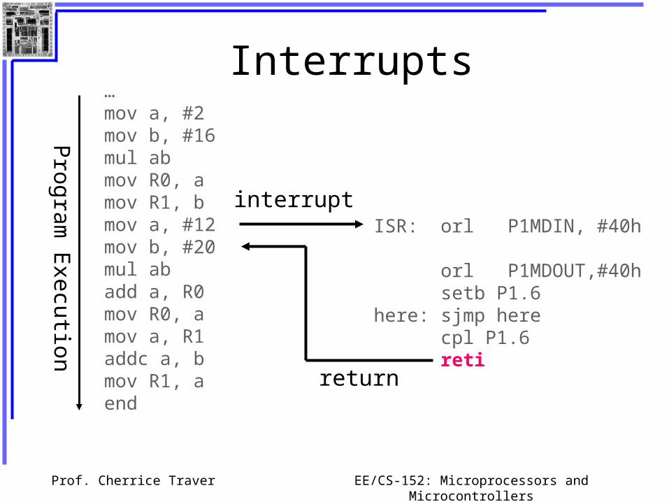
Interrupts…mov a, #2mov b, #16mul abmov R0, amov R1, bmov a, #12mov b, #20mul abadd a, R0mov R0, amov a, R1addc a, bmov R1, aend
Program
Execution
interruptISR: orl P1MDIN, #40h
orl P1MDOUT,#40h setb P1.6
here: sjmp herecpl P1.6 reti
return

Prof. Cherrice Traver EE/CS-152: Microprocessors and Microcontrollers
Interrupt Sources
• Original 8051 has 5 sources of interrupts– Timer 1 overflow
– Timer 2 overflow
– External Interrupt 0
– External Interrupt 1
– Serial Port events (buffer full, buffer empty, etc)
• Enhanced version has 22 sources– More timers, programmable counter array, ADC, more
external interrupts, another serial port (UART)

Prof. Cherrice Traver EE/CS-152: Microprocessors and Microcontrollers
Interrupt Process
If interrupt event occurs AND interrupt flag for that event is enabled, AND interrupts are enabled, then:
1. Current PC is pushed on stack.
2. Program execution continues at the interrupt vector address for that interrupt.
3. When a RETI instruction is encountered, the PC is popped from the stack and program execution resumes where it left off.
Prof. Cherrice Traver EE/CS-152: Microprocessors and Microcontrollers
Interrupt Priorities
• What if two interrupt sources interrupt at the same time?
• The interrupt with the highest PRIORITY gets serviced first.
• All interrupts have a default priority order. (see page 117 of datasheet)
• Priority can also be set to “high” or “low”.

Prof. Cherrice Traver EE/CS-152: Microprocessors and Microcontrollers
Interrupt SFRs
Global Interrupt Enable – must be set to 1 for any interrupt to be enabled
Interrupt enables for the 5 original 8051 interrupts:Timer 2
Serial (UART0)Timer 1
External 1Timer 0
External 01 = Enable0 = Disable
Prof. Cherrice Traver EE/CS-152: Microprocessors and Microcontrollers
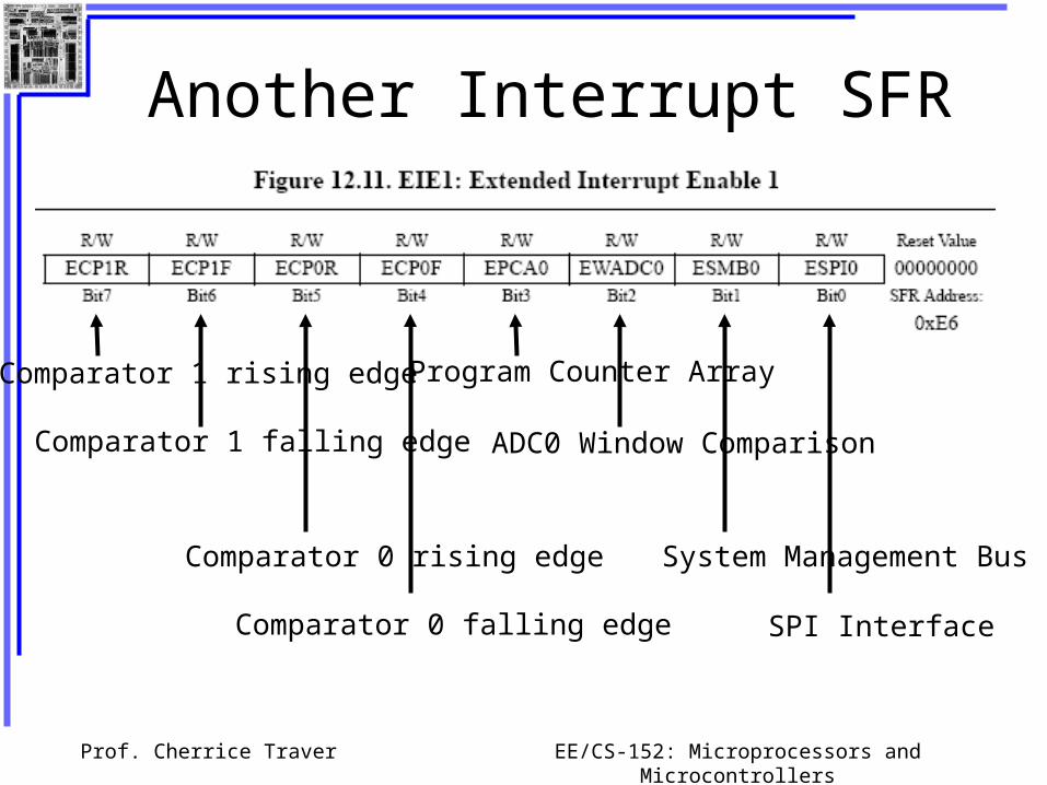
Another Interrupt SFR
Comparator 1 rising edge
Comparator 1 falling edge
Comparator 0 rising edge
Comparator 0 falling edge
Program Counter Array
ADC0 Window Comparison
System Management Bus
SPI Interface

Prof. Cherrice Traver EE/CS-152: Microprocessors and Microcontrollers
Another Interrupt SFR
Serial (UART) 1
External 7 External 6
ADC 1
Timer 4
ADC 0
Timer 3
External Clock source Valid

Prof. Cherrice Traver EE/CS-152: Microprocessors and Microcontrollers
External Interrupts
• /INT0 (Interrupt 0) and /INT1 (Interrupt 1) are external input pins.
• Interrupt 6 and Interrupt 7 use Port 3 pins 6 and 7:INT 6 = P3.6INT 7 = P3.7
These interrupts can be configured to be– rising edge-triggered– falling edge-triggered

Prof. Cherrice Traver EE/CS-152: Microprocessors and Microcontrollers
External Interrupts
Interrupt flags:
0 = no falling edges detected since bit cleared
1 = falling edge detected
Interrupt Edge Configuration:
0 = interrupt on falling edge
1 = interrupt on rising edge

Prof. Cherrice Traver EE/CS-152: Microprocessors and Microcontrollers
Example Configuration
Configure Port 3, bit 7 (the pushbutton switch) to interrupt when it goes low.
anl P3MDOUT, #0x7F ; Set P3.7 to be an input
setb P3.7
mov XBR2, #40h ; Enable crossbar switch
mov P3IF, #0 ; Interrupt on falling edge
mov EIE2, #020h ; Enable EX7 interrupt
mov IE #80h ; Enable global interrupts

Prof. Cherrice Traver EE/CS-152: Microprocessors and Microcontrollers
Interrupt Vectors
Each interrupt has a specific place in code memory (a vector) where program execution (interrupt service routine) begins (p17).
Examples:External Interrupt 0: 0x0003Timer 0 overflow: 0x000BExternal Interrupt 6: 0x0093External Interrupt 7: 0x009B
Note that there are only 8 memory locations between vectors.

Prof. Cherrice Traver EE/CS-152: Microprocessors and Microcontrollers
Interrupt Vectors
To avoid overlapping Interrupt Service routines, it is common to put JUMP instructions at the vector address. This is similar to the reset vector.
cseg at 009B ; at EX7 vector ljmp EX7ISR
cseg at 0x100 ; at Main programMain: ... ; Main program
... EX7ISR:... ; Interrupt service routine
... ; Can go after main program reti ; and subroutines.

Prof. Cherrice Traver EE/CS-152: Microprocessors and Microcontrollers
Example Interrupt Service Routine; EX7 ISR to blink the LED 5 times. ; Modifies R0, R5-R7, bank 3.;----------------------------------------------------ISRBLK: push PSW ; save state of status word
mov PSW, #18h ; select register bank 3 mov R0, #10 ; initialize counter
Loop2: mov R7, #02h ; delay a whileLoop1: mov R6, #00hLoop0: mov R5, #00h djnz R5, $ djnz R6, Loop0 djnz R7, Loop1 cpl P1.6 ; complement LED value djnz R0, Loop2 ; go on then off 10 times
pop PSW mov P3IF, #0 ; clear interrupt flag reti
Prof. Cherrice Traver EE/CS-152: Microprocessors and Microcontrollers
Practice Interrupting…