Embed Size (px)
Citation preview

Products for Railway Networks
You will find what you are looking for

www.horstmanngmbh.com | [email protected]
In-house manufacturing
Component testing
High voltage laboratory
Dipl.-Ing. H. Horstmann GmbH is a medium-sized company based in Heiligenhaus near Düsseldorf (Germany). The company was founded in 1946 by Heinrich Horstmann. Since that time it has been a successful family-owned com-pany. Due to its long experience and the ongoing expan-sion activities in research and development as well as in production facilities Dipl.-Ing. H. Horstmann GmbH is today recognized as the leading manufacturer in medium voltage technology for:
� short-circuit and earth fault indicators � solutions for remote monitoring � voltage detectors and voltage detecting systems � earthing devices and accessories
The worldwide distribution is covered by both our own highly qualified sales force and trade agents.
Our products meet the highest quality requirements and are developed and manufactured in own production facilities in Germany. In order to respond to these demands, we have a very high vertical depth of production (e. g. own SMD assembly lines) as well as an own research and development department with state-of-the-art testing and measuring equipment. Besides the electronics manufactur-ing, we have also a mechanical production facility for safety material.
Our company has been certified according to DIN EN ISO 9001 since 1996.
Company profile
Head office in Heiligenhaus

www.horstmanngmbh.com | [email protected] 3
The safe and reliable transport of passengers and goods is the primary concern of railway network operators. In order to achieve this, not only the trains, but also the tracks need to be monitored and maintained.Horstmann offers products and system solutions for the rapid location of faults in the event of short-circuits or lightning strikes, as well as for continuous monitoring of railway electrical systems. In the event of disturbances or outages fault finding is often laborious and time-consuming. It is necessary to drive or walk along the entire electrified section in order to find the fault location. Horstmann fault indicators divide the electrified sections into sub-sections. In the event of a fault, all fault information is sent to the control room, clearly indicating the exact fault location. This permits maintenance staff to go straight to the fault location and quickly implement the necessary measures. This saves time and money and ensures customer satisfaction for all rail passengers.When there are no faults, monitoring provides the railway network operator with a full overview of the most important net-work parameters at all times. Horstmann also offers products which allow for work to safely be carried out on the tracks. These include voltage detection systems for determining that there is no voltage present in overhead line systems which provide power to the overhead contact lines.Horstmann products are precisely adjusted to the requirements of railway networks and designed for use with the typical frequencies 16.7 Hz.
� Smart Navigator 2.0 Rail — Quick location of faults in overhead line systems and on catenary masts � Pole Master Rail — Long-distance communication of reports of faults in overhead line systems to a central location � BO-A 2.0 — Determining voltage presence or absence in overhead line systems of electrified railways � BO-A AC / DC — Focus: Determining the absence of voltage for DC and AC applications with residual voltage � Polaris — Electrified sections with autotransformers, monitoring of return currents � Cosmo Rail — Earthing line monitoring system � Wega 2.2 C Rail and Wega 1.2 C Rail — Determining voltage presence or absence in switchgears for powering railways � Earthing and short-circuiting device — for safe working in switchgears
Railway networks Products and system solutions

www.horstmanngmbh.com | [email protected]
Smart Navigator 2.0 RailDirectional overhead faulted circuit indicator with monitoring
Smart Navigator 2.0 Rail
Fault messages containing information about short-circuits and fault current direction help to clearly identify problem situations. Every fault is signalled to the control room within one minute.
Energy managementPole-mounted units with solar panels are used to ensure supply and control room communication. Alternatively, these can be powered from a DC or AC auxiliary power supply.The high battery capacity of the Smart Navigators guar-antees a service life of >10 years, and any load current extends the service life.
ClampThanks to the innovative clamping mechanism, unintention-al detaching from the overhead line due to environmental influences is impossible.With a hot stick, the Smart Navigator 2.0 Rail can be mount-ed on an overhead line up to 12 meters high, even under live conditions. Likewise, it also can be uninstalled again without any problems.
Product features � Intelligent fault detection — reduces outage times � Overhead line monitoring — data for the evaluation of the network condition
� Innovative installation — on live conductors and from the ground
� Remote maintenance — configuration and updates from the control room
Intelligent fault detectionThe proven overcurrent detection alogrithm detects fault currents reliably under a wide range of network situations. Individual parameter settings tailor the system perfectly for all locations in your overhead line network, eliminating false tripping.The Smart Navigator 2.0 Rail can be quickly and easily mounted in overhead line systems. Typical mounting loca-tions are longitudinal and transverse disconnects, catenary lines, amplifier lines, bypass lines and feeder lines in auto-transformer systems.
Pole Master Rail

www.horstmanngmbh.com | [email protected] 5
Technical data Smart Navigator 2.0 RailTrip current 10 — 1.200 A (adjustable)
Current measurement accuracy±2 A (0 — 10 A) 3 % (10 — 600 A)10 % (600 — 10.000 A)
Indication Ultra-bright high power LEDs (red, green, yellow), indication for maintenance purposes only. Deacti-vated in normal operation, as there is a risk of confusion with signalling and control systems
Directional indication Is supportedReset Automatic time reset (1 minute)
Power supplySmart Navigator 2.0 Rail: Lithium cells, replaceable, shelf life >10 yearsPole Master Rail: � Solar supply (12 V DC) � Up to 8 weeks buffer time using integrated backup battery (depending on dial-up interval)
Max. permissible voltage 7.2 — 46 kV / 16.7 HzWithstand current 800 A at <50 °C ambient temperature, 25 kA / 3 sTemperature measurement range −40 to +130 °C
Remote signal � Fault detection � Fault current direction � Data such as temperature, signal field strength and battery status
Server � Cloud solution for fast system integration: iHost Cloud � Connection to the control room: iHost Solo or iHost Pro � Functionality monitoring
CommunicationSmart Navigator 2.0 Rail: Lokal: 868 MHz short-range radio (50 m)Pole Master Rail: �WAN: 4G-LTE modem (2G fallback) � Local: 868 MHz short-range radio (50 m)
Cable diameter range ≤33 mm Adjacent conductor immunity No influence by adjacent conductors with a horizontal distance of >250 mm from the indicatorCoupling One Pole Master Rail with up to four Smart Navigator 2.0 RailHousing UV resistant reinforced plastic, IP65Dimensions 223 x 131 mm (H x W)Weight Approx. 1.0 kg Temperature range —40 °C to +85 °C
Equipment set Optional supplements Page1 Smart Navigator 2.0 Rail Order No. 44-1200-001 Bird guard for Pole Master Rail 181 Pole Master Rail Order No. 44-1200-101 USB-Transmitter 18
Magnet (Test/Reset) 18Installation Tool 18Hot Stick 18
ServiceSmart Navigators 2.0 Rail are successfully used worldwide, on all continents, to detect and remotely report network faults. Therefor, the Smart Navigator 2.0 Rail is tailored to the country-specific radio approvals and the different frequency ranges of the network operators.We are happy to support you with the connection to your server solution for the control room and the design of the network-specific tripping characteristics.Implement your individual projects together with us: +49 2056 976 0.
Remote signalling and monitoringThanks to remote signalling, the complex, high-quality and diverse sensor technology enables clear monitoring and thus direct insight into your overhead line network.Remote maintenance such as software updates or config-uration adjustments can be performed via the GSM / LTE connection.

www.horstmanngmbh.com | [email protected]
� VDE version — according to DIN VDE 0681-6 IEC version — based on IEC 61243-1 category S
� Voltage Indicator optical or optical-acoustical
� Extension or Plug-in system — quick and easy to use � Integrated self-test device — increased safety � Light weight — easy handling and transportation � Use even in precipitation � Length of 4.7 m — voltage detection from the ground � Signal color storage bag - safe transport � Backpack carrying belts + hand carrying belts - comfortable transport
� Highest reliability and user comfort
Produkt features The BO-A 2.0 is a voltage detector for medium voltage overhead line systems of electrified railways, substations and electrical indoor installations. It is designed to detect the absence or presence of voltage during maintenance work for example. The voltage detector BO-A 2.0 is suitable for use in 16.7 / 50 / 60 Hz networks. If the voltage detector BO-A 2.0 is used in a network with a deviating frequency, a visual and audible signal is activated. In this case the network situation must be verified.The BO-A 2.0 is designed according to IEC 61243-1 resp. DIN VDE 0681-6, depending on the version. The voltage detector is ready for the global market.According to the German accident prevention standard DGUV Regulation 3 (Table 1c), the device is subject to maintenance tests with intervals of not more than 6 years.
BO-A 2.0For Overhead line systems
BO-A 2.0
Deutsche
Bahn —
Approval

www.horstmanngmbh.com | [email protected] 7
Green LED: Stand-by state and Voltage not presentRed LED: Voltage presentPushbutton: On/Off-PushbottonBlack button: Acoustical indicator
BO-A 2.0 indication and control panel
Technical data BO-A 2.0Use In dry and wet conditionsIndication “Ready-to-operate”: green LED (after passed self-test)
“Voltage present”: red LED and acoustical signal“Voltage not present”: green LED and no acoustical signal
Period of “Stand-by state” 65 s ±15 sType of indication According to group III IEC 61243-1Nominal voltage /nominal frequency
VDE version: 11 kV / 16.7 Hz or 15 kV / 16.7 HzIEC version: 15 kV / 16.7 Hz, 25 kV / 50 Hz or 25 kV / 60 Hz
Properties of the insulating stick Passed test as insulating element for leakage current at 1.2 x Vr for 1 min
Power supply Lithium cells, battery service life: 6 years based on 10 ready -to-operate cycles per day for a total of 230 work days per year
Operating temperature —25 to +70 °C, climatic class N and WTransportation length <1,111 mm
Minimum length insulating element >520 mm (Insulating sticks or a telescopic stick can be assembled by a plug-in adapter)
Nom
inal
vol
tage
[kV]
/N
omin
al fr
eque
ncy
[Hz]
Tota
l len
gth
[mm
] ±5
0 m
m
Inse
rtion
dep
th [m
m]
BO-A 2.0 (VDE version) BO-A 2.0 (IEC version) Order No
11 kV / 16,7 Hz 4.700 1.790 Insulating sticks (pluggable) — 50-1510-00115 kV / 16,7 Hz 4.700 1.790 Insulating sticks (pluggable) — 50-1510-00215 kV / 16,7 Hz max. 5.400 1.790 Plug-in adapter/Teleskopic stick — 50-1510-20215 kV / 16,7 Hz 4.700 1.790 — Insulating sticks (pluggable) 50-1511-00125 kV / 50 Hz 4.700 1.790 — Insulating sticks (pluggable) 50-1511-00225 kV / 60 Hz 4.700 1.790 — Insulating sticks (pluggable) 50-1511-00325 kV / 60 Hz 0.970 — Universal adapter 50-1511-004
Optional accessories PagePlug-in adapter/Telescopic stick 19Universal adapter/Telescopic stick 19Insulating sticks (pluggable) 19Storage bag, orange, with silver reflective strips 19
Storage bag, yellow, with silver reflective strips 19

www.horstmanngmbh.com | [email protected]
BO-A AC/DCThe new DC multifunction voltage detector for overhead line systems of electrified railways
BO-A AC/DC
BO-A AC/DC Indicator and Control Panel
Yellow LED: Residual voltage indicationGreen LED: Stand-by state and w Voltage not presentBlack Button: Acoustical indicator
Red LED: Voltage present
Blue Pushbutton: On/Off-Pushbutton
Red/blue LED: Polarity indication
� One device for DC and AC voltage networks � Voltage Indicator optical or optical-acoustical
� Plug-in system — quick and easy to use � Integrated self-test device — increased safety � AC/DC-Residual-Voltage Indicator � DC +_ Polarity Indicator � Low weight — easy handling and transport � Use even in precipitation � Length of 4.7 m — voltage detection from the ground � Magnetic earthing contact with scraper for removing the rust layer
The voltage detector BO-A AC/DC is a two-pole test equipment for overhead line systems of electrified railways and other typical voltage applications. It provides clear evidence of the presence or the absence of the operating voltage.
Produkt features
They are suitable for DC and AC voltage networks.When the BO-A AC / DC is connected to a live line, an opti-cal and acoustical signal is activated. A DC or AC voltage network is detected and indicated automatically.The BO-A AC / DC is designed and tested according to IEC 61243-1, -2 and DIN VDE 0681-6. The voltage detector is ready for the global market.According to the German accident prevention standard DGUV Regulation 3 (Table 1c), the device is subject to maintenance tests with intervals of not more than 6 years.

www.horstmanngmbh.com | [email protected] 9
Technical data BO-A AC/DC
Utilization � DC and AC voltage networks from 100 V to 3,000 V � Use in dry and rainy conditions
Indication
„Stand-by“: green LED (after successful self-test) „Voltage present“: red LED and acoustical signal
for DC with static polarity indication (blue/red)for AC without polarity indication
„Voltage not present“: green LED, no acoustical signalAC/DC residual voltage indicator: yellow flashing LED for: AC residual voltage detection from 50 V RMS or DC residual voltage detection from ±75V DC +_ Polarity Indicator: Detecting DC voltage polarity: red or blue flashing LED
Period of „Stand-by state“ � Ready-to-operate time: 60 s (standard value), longer ready-to-operate times available, too � Stand-by state: Automatic self-activation optionally available
Type of indication According to group III IEC 61243-1
Nominal voltage /nominal frequency
The following three standard versions are available:• Un = 100 V ... 300 V • Un = 300 V ... 900 V • Un = 1000 V ... 3000 V See imprint on type plate, tolerance ± 10 %16,7 — 60 Hz
Properties of the insulating stick Passed test as insulating element for leakage current at 1.2 x Vr for 1 minPower supply Lithium cells, 6 years based on 10 ready -to-operate cycles per day and 230 work days per yearTransportation length <1.100 mm (incl. hook)Minimum length insulating element >520 mmOperating temperature -25°C to +65°C
Nominal voltage [kV] Nominal frequency [Hz]
Tota
l len
gth
[mm
]±5
0 m
m
BO-A AC/DC version Order No.
100-300 V (AC) / 50 Hz or DC 4.700 Insulating sticks (pluggable) 50-1600-002300-900 V (AC) / 50 Hz or DC 4.700 Insulating sticks (pluggable) 50-1600-003100-300 V (AC) / 50 Hz or DC 4.700 Universal adapter/Extension stick 50-1600-102300-900 V (AC) / 50 Hz or DC 4.700 Universal adapter/Extension stick 50-1600-103100-300 V (AC) / 50 Hz or DC 4.700 Plug-in adapter/Extension stick 50-1600-202300-900 V (AC) / 50 Hz or DC 4.700 Plug-in adapter/Extension stick 50-1600-2031000-3000 V (AC) / 50 Hz or DC 4.700 Plug-in adapter/Extension stick 50-1600-204
Optional accessories PagePlug-in adapter/Telescopic stick 19Universal adapter/Telescopic stick 19Insulating sticks (pluggable) 19Earthing bridge 19Storage bag, orange, with silver reflective strips 19Storage bag, orange, with silver reflective strips 19

www.horstmanngmbh.com | [email protected]
Polaris
PolarisMonitoring of return currents
Product features
The Polaris performs a continuous monitoring of parallel connecting cables in 2 x 25 kV railway systems, which typically carry the return current. If the connection of one of these cables deteriorates, it will be detected and selectively displayed. In addition, any undesired increase of the earth potential is detected and displayed.The above events are remotely reported to the control room. This enables the railway asset management to send the service team to the point of failure in a targeted manner.
� Monitoring of lines in the reverse current system of electrical railway supply
� Monitoring the earth potential � Relay for remote signal
Single-phase current sensor
Autotransformer
Busbar
Earth grid
Rail-earth voltage
www.horstmanngmbh.com | [email protected] 11
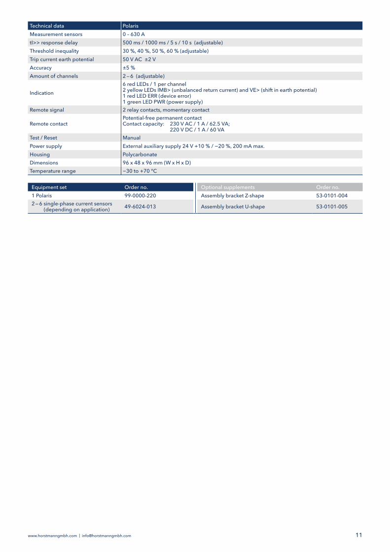
Technical data PolarisMeasurement sensors 0 – 630 AtI>> response delay 500 ms / 1000 ms / 5 s / 10 s (adjustable)Threshold inequality 30 %, 40 %, 50 %, 60 % (adjustable)Trip current earth potential 50 V AC ±2 VAccuracy ±5 %Amount of channels 2 — 6 (adjustable)
Indication6 red LEDs / 1 per channel2 yellow LEDs IMB> (unbalanced return current) and VE> (shift in earth potential)1 red LED ERR (device error)1 green LED PWR (power supply)
Remote signal 2 relay contacts, momentary contact
Remote contactPotential-free permanent contactContact capacity: 230 V AC / 1 A / 62.5 VA; 220 V DC / 1 A / 60 VA
Test / Reset ManualPower supply External auxiliary supply 24 V +10 % / −20 %, 200 mA max.Housing PolycarbonateDimensions 96 x 48 x 96 mm (W x H x D) Temperature range −30 to +70 °C
Equipment set Order no. Optional supplements Order no.1 Polaris 99-0000-220 Assembly bracket Z-shape 53-0101-0042 — 6 single-phase current sensors (depending on application) 49-6024-013 Assembly bracket U-shape 53-0101-005

www.horstmanngmbh.com | [email protected]
Cosmo Rail and sensor
Cosmo RailMonitoring short-circuit currents
Product feature
The Cosmo Rail short-circuit indicator is intended for de-tecting short-circuit currents in the overhead contact line earthing system of 16.7 Hz / 15 kV traction power systems. The Cosmo Rail monitors short-circuit currents flowing through the earthing cable between the catenary mast and the track. The Cosmo Rail consists of a display unit and a sensor. Both units are permanently connected to each other via a cable. The unit is delivered ready for operation. Additional meas-ures for functional efficiency are not necessary.The display unit consists of the electronic evaluation unit in installation housing with a mounting plate for erecting the mast and contains the optical display elements.The sensor consists of the sensor itself and a clip-on yoke for attaching to the earthing cable.The fault detection system enables remote read-out during an inspection drive with a rail vehicle and fault location in the event of a short-circuit by displaying the read-out device status of the Cosmo Rail.
� Monitoring of short-circuit currents flowing through the earthing cable between the catenary mast and the track
Display unit
Sensor

www.horstmanngmbh.com | [email protected] 13
Long Range Reader
Technical data Cosmo RailFault detection Short circuit, lightning strike, cable interruption in 16.7 Hz/15 kV traction current systemsShort-circuit IK response value 1,000 A (±10 A), other values on requestILS lightning strike response value 500 A (±10 A)Reset after test Manual with magnet or automatic reset after 30 secondsReset after excitation Manual only with magnetRemote signal Passive RFID technology
Optical displays 4 short-circuit indicators, optionally available without indicators1 yellow LED for reset
Power supply Long-life lithium cell, shelf life >20 years, >1,500 displays with indicator
Housing (indicator and sensor) IP65
Connecting cable 32-2000-001: Length 2 m, shielded32-2000-002: Length 4 m, shielded
Temperature range −30 °C to +70 °C
Equipment set Order no. Optional supplements Order no.1 Cosmo Rail 2 m line length 32-2000-001 Long Range Reader on request1 Cosmo Rail 4 m line length 32-2000-002 Short Range Reader on request
Short Range Reader
www.horstmanngmbh.com | [email protected]
Product features
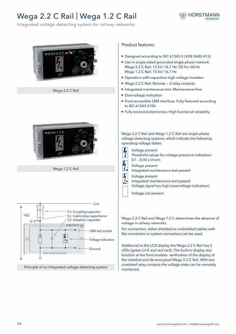
� Designed according to IEC 61243-5 (VDE 0682-415) � Use in single-sided grounded single-phase network Wega 2.2 C Rail: 15 kV / 16,7 Hz / 50 Hz / 60 Hz Wega 1.2 C Rail: 15 kV / 16,7 Hz
� Operation with capacitive high-voltage insulator � Wega 2.2 C Rail: Remote — 2 relay contacts � Integrated maintenance test: Maintenance-free � Overvoltage indication � Front accessible LRM interface: Fully featured according to IEC 61243-5106
� Fully enclosed electronics: High functional reliability
Wega 2.2 C Rail and Wega 1.2 C determines the absence of voltage in railway networks.For connection, either shielded or unshielded cables with flat connectors or system connectors can be used.
Additional to the LCD display the Wega 2.2 C Rail has 2 LEDs (green U=0 and red U≠0). The built-in display test function at the front enables verification of the display of the installed and de-energised Wega 2.2 C Rail. With two unrelated relay contacts the voltage state can be remotely monitored.
Wega 2.2 C Rail and Wega 1.2 C Rail are single-phase voltage detecting systems, which indicate the following operating voltage states:
Voltage present Threshold values for voltage presence indication: 0.1 – 0.45 x VnomVoltage present Integrated maintenance test passedVoltage present Integrated maintenance test passed Voltage signal too high (overvoltage indication)
Voltage not present
Wega 2.2 C Rail
Wega 1.2 C Rail
Line
C1: Coupling capacitorCL: Cable stray capacitanceC2: Adaption capacitor
LRM test socket
Voltage indication
Ground
ULE
WWW.HORSTMANN.COM
Wega 2.2 C Rail | Wega 1.2 C RailIntegrated voltage detecting system for railway networks
Principle of an integrated voltage detecting system

www.horstmanngmbh.com | [email protected] 15
Equipment set1 display unit
Wega 2.2 C Rail, 16.7 Hz Order no. 51-2251-001Wega 2.2 C Rail, 50 Hz / 60 Hz Order no. 51-2251-002Wega 1.2 C Rail, 16,7 Hz Order no. 51-1255-001
Technical data Wega 2.2 C Rail Wega 1.2 C RailNominal frequency 16.7 / 50 / 60 Hz 16,7 Hz
Interface 1 LRM measuring sockets and 1 earth socket LRM system, 14 mm distance between sockets, with captive anti-dust cap
Indication � LCD display with arrow, dot and wrench tool � LED indication, U=0 and U≠0and auxiliary power present
� LCD display with arrow, dot and wrench tool
Remote signal 2 relay contacts, alternating contact —
Power supply � LCD display: fed by measuring voltage � Relay via 24 – 230 V AC / DC power supply
� LCD display: fed by measuring voltage
Temperature range −25 to +65 °CHousing Polycarbonate, IP54
Dimension 96 x 48 x 52 mm (L x H x D), Cut-out on system side: 92+0,8 x 45+0,6 mm
96 x 48 x 52 mm (L x H x D), Cut-out on system side: 92+0,8 x 45+0,6 mm

www.horstmanngmbh.com | [email protected]
Single-pole earthing and short-circuiting cable
� Designed according to IEC 61230 (VDE 0683-1 or -100) � Cables assembled from highly flexible copper conductors (with transparent insulation)
� Cable lug on each cable end
Product features
Earthing and short-circuiting devicesSingle-pole without connecting elements
Each cable lug is provided with a 13 mm diameter hole. Any type of connecting element can be used for the earth-ing cables.
Other versions and
combinations on request
Cross section of copper conductor [mm²]
Rated valuesIr [kA]/ tr = 1 s
Cable length [mm²]
Order no. Optional supplements Page
25 4.9 800 61-0101-015 Phase connecting elements 17 25 4.9 2,000 61-0101-003 Earth connecting elements 17 25 4.9 2,500 61-0101-016 Hot sticks see main catalogue 35 6.9 2,000 61-0102-003 Earthing sticks see main catalogue 35 6.9 3,000 61-0102-009 Wall holders see main catalogue 50 9.9 1,200 61-0103-001 50 9.9 1,500 61-0103-002 50 9.9 2,000 61-0103-003 70 13.8 800 61-0104-018 70 13.8 1,200 61-0104-001 70 13.8 1,500 61-0104-002 70 13.8 2,000 61-0104-003 95 18.7 1,200 61-0105-001 95 18.7 1,500 61-0105-002 95 18.7 3,000 61-0105-009 95 18.7 4,000 61-0105-008 95 18.7 5,000 61-0105-010120 23.7 1,000 61-0106-012120 23.7 1,200 61-0106-001120 23.7 1,500 61-0106-002120 23.7 2,000 61-0106-003120 23.7 3,000 61-0106-006150 29.6 1,200 61-0107-001150 29.6 1,500 61-0107-002150 29.6 2,000 61-0107-003150 29.6 2,500 61-0107-009150 29.6 3,000 61-0107-006
Other cable lengths available on request

www.horstmanngmbh.com | [email protected] 17
Line clamps with bayonet fitting
Connection to Order no.
Ball
pin
Ø
[mm
]
T-co
nnec
tion
bolt
[mm
]
Roun
d co
nduc
tor
[mm
]
Flat
con
duct
or[m
m]
Rate
d va
lues
Ir [k
A]/
tr =
1 s
Uni
vers
al c
ompa
ct
clam
p
Uni
vers
al p
hase
cl
amp
Uni
vers
al p
hase
cl
amp
Ball
tong
20 — — — 18.7 — — — 64-0103-00125 — — — 29.7 — — — 64-0103-00220 15 4 — 15 0 — 25 13.8 64-0101-001 — — —20 — 10 — 20 0 — 22 13.8 — 64-0102-001 — —25 15 10 — 25 0 — 28 23.7 — 64-0102-002 — —20 / 25 15 10 — 25 0 — 28 18.7 / 23.7 — — 64-0102-003 —25 / 30 15 10 — 30 0 — 28 23.7 — — 64-0102-004 —
Earth connecting elementsEarth clamp with wing boltClamping range[mm]
Rated valuesIr [kA] / tr = 1 s
Order no.
23 18.7 64-0201-00338 29.6 64-0201-004
Earth clamp with T-handleClamping range[mm]
Rated valuesIr [kA] / tr = 1 s
Order no.
23 18.7 64-0201-00138 29.6 64-0201-002
Earthing terminalCable cross section[mm²]
Rated valuesIr [kA] / tr = 1 s
Order no.
50 9.9 64-0202-00370 13.8 64-0202-00495 18.7 64-0202-005
Earth clamp with bayonet connectorClamping range[mm]
Rated valuesIr [kA] / tr = 1 s
Order no.
23 18.7 64-0201-00538 29.6 64-0201-006
Cable lug with captive wing nutCable cross section[mm²]
ThreadRated values
Ir [kA] / tr = 1 sOrder no.
50 M12 9.9 64-0203-00170 M12 13.8 64-0203-00295 M12 18.7 64-0203-003
Cable lug with captive wing boltCable cross section[mm²]
ThreadRated valuesIr [kA] / tr = 1 s
Order no.
50 M12 9.9 64-0204-00170 M12 13.8 64-0204-00295 M12 18.7 64-0204-003
Cable lug with 13 mm holeCable cross section[mm²]
Rated values
Ir [kA] / tr = 1 sOrder no.
50 9.9 64-0205-00370 13.8 64-0205-00495 18.7 64-0205-005
Further clamps and connecting points are in the main catalogue.

www.horstmanngmbh.com | [email protected]
AccessoriesSmart Navigator 2.0 Rail
Hot Stick with hook for Smart Navigator 2.0 Rail installations and removals on overhead line systems.
Nominal voltagemax. [kV]
Dimensions [mm]Order no.
a b c1 — 24 1,200 500 310 65-0301-0011 — 36 2,000 900 310 65-0301-0021 — 36 3,000 900 1,310 65-0301-0031 — 52 2,000 900 310 65-0301-004
b
a
c
Hot stick with hook (according to DIN VDE V 0681-1)
Item Order no.Installation tool for Smart Navigator 2.0 Rail 49-6006-005Extension stick with universal end fitting (extended length: 6.43 m, retracted length: 1.63 m)Rated voltage: 123 kV (only when extended)
65-0305-001
Installation tool
Extension stick with universal end fitting
Installation tool for Smart Navigator 2.0 Rail installations and removals on overhead line systems.
Order no.Bird guard for Pole Master Rail 44-9900-001
Order no.USB-Transmitter 28-5000-001
Order no.Magnet (Test / Reset) 49-6001-002

www.horstmanngmbh.com | [email protected] 19
BO-A 2.0 and BO-A AC/DC
Storage bag incl. BO-A 2.0 Storage bag incl. BO-A AC/DC
Transportation and storage bag for BO-A 2.0 and BO-A AC/DC
ItemDimensions [mm]
Order no.L H D
Transportation bag, orange, with silver reflecive strips and shoulder strap 1.130 340 100 52-0104-106
Transportation bag, yellow, with silver reflecive strips and shoulder strap 1.130 340 100 52-0104-107
Earthing bridge
For Item Order no.BO-A AC/DC 52-0108-052
Item Order no.Plug-in adapter/Telescopic stick 52-0108-051Universal adapter/Telescopic stick 65-0305-001Insulating stick (pluggable) 52-0108-008
Telescopic/Plug-in system

Dipl.-Ing. H. Horstmann GmbHHumboldtstraße 242579 Heiligenhaus
T +49 2056 976-0F +49 2056 976-140
All rights reserved to make technical changes.101101-0001/75/09.21