Embed Size (px)
Citation preview

1
Faculty of Civil and Industrial Engineering
Bachelor in Chemical Engineering
Production of Iron Carbide
Martina Caldaroni
Academic Year 2013/2014

2
INDEX
1.INTRODUCTION page 4
2.The Iron Carbide page 7
2.1 Properties page 7
2.2 Advantages: Metallurgical and Environmental benefits page 9
3. The Iron Carbide for Electric Arc Furnace page 10
3.1 Introduction to Electric Arc Furnaces page 10
3.2 Utilization of Iron Carbide in an EAF page 11
4. History of the production processes page 14
4.1 Nucor Corporation page 15
4.2 Qualitech Steel page 17
4.3 Process Improvements page 18
5. Production Process page 18
5.1 . Introduction to Fluidized Beds page 19
5.2 . Overview of the Process page 21
5.3 . Storage of the Mineral page 22
5.4 . Heating of the Mineral page 23
5.5 . Reactor Charging page 23
5.6 . Fluidized Bed Reactor page 23
5.7 . Treatments of the Product page 25
5.8 . Gas Treatment System page 26
5.9 . Process Water page 27
6. Conclusions page 28
Bibliography page 29

3
Introduction
The purpose of this thesis is to illustrate the process of innovation, still at the experimental stage,
for the production of iron carbide from hematite at a low temperature, in order to produce steels
of high purity and at low cost.
Currently, the production of steel is obtained basically with two manufacturing cycles: electrical
cycle or from scrap and full cycle or mineral. In the diagram (fig.1) is given a schematization of
two cycles of steel production.
Fig.1: Summary of the Productive Cycles of the Steel [1]

4
As we can see, the first method provides for the formation of the cast iron in the furnace and
consequently the decarburization in the converter with oxygen in. The "BOF", or basic oxygen
furnace, which has the purpose of converting the cast iron into liquid crude steel through the
injection of oxygen, while the other method forms the steel in the electric furnace from the
sponge iron derived from direct reduction.
Let us then, consider the second production cycle.
They are called, somewhat unhelpfully; direct reduction processes and are those processes that
lead directly from the ore to the product metallic iron, without passage of the metal in a liquid
state.
The product is, as already said, a sponge iron (DRI, Direct Reduced Iron), meaning a metal
structure of high porosity, containing inclusions and abundant phases that are not metal from the
gangue and oxides that were not reduced. In direct reduction processes the process temperature is
lower than that of liquid iron and, thus, there is no possibility of separation between molten metal
and slag, which occurs in processes where one obtains the melting of metal.
The direct reduction processes, due to their main characteristic, which is that they are carried out
at temperatures lower than the melting point of the metal product, do not allow for any
separation of the gangue nor any real process of refining.
A particular characteristic to be taken into account in handling and storing the sponge iron is
their high reactivity with oxygen that can cause the material to become pyrophoric. Pyrophoric
products, in cases where the products were obtained from processes that are carried out at low
temperatures ( < 600 °C) can be pyrophoric, even at room temperature. Hydrogen gas may be
produced from the reaction of metallic iron with water. It is to be expected, before an expedition
by sea, that the product would be exposed to an "aging" process, which produces a thin oxide
layer to passivate the surface of the product and/or the briquetting of the sponge for mechanical
compression, so that the product, which takes the name of HBI (Hot Briquetted Iron), can be sent
to the steelmakers in the form of briquettes with a high specific gravity, low porosity and high
mechanical strength characteristics
One of the most important characteristics of these products is the degree of metallization. The
degree of metallization is defined as the ratio between metallic iron and total iron. The difference
between the two (total iron less metallic iron) is the iron that was not reduced during the process,
and remained as oxide. Thus some of the iron remains with bound oxygen in the sponge iron
product.
Products from these processes of reduction can find two main types of use in the iron and steel
industry: as a partial replacement of minerals in blast furnaces for the production of cast iron or
in electrical ovens or furnaces of the steel plant for partial or total replacement of the scrap.
In the first case iron content with a relatively low degree of metallization is acceptable. The main
results that can be expected from the use of reduced iron in a blast furnace are increases in
productivity and economies in the consumption of coke.

5
The use of Direct Reduced Iron for the production of steel has been tested mainly in the electric
arc furnace. In this use, the direct reduced iron is in competition with the scrap iron and the
evaluation of the results of the tests is usually done by taking as reference the normal charging
based on the scrap. For its use in the steel mill, It is required that the direct reduced iron have a
greater purity, a high iron content and a high degree of metallization. The residual oxygen must
be removed during the steel manufacturing process and is primarily removed as carbon
monoxide. If the oxygen content in the charge is high, there is a need to increase the charge of
carbon. Increased oxygen content in the charge can increase the time of refining and
consumption of electricity, due to the energy required for the reduction of the residual iron
oxides. [2]
In recent years, therefore, there has been ongoing research into how to produce iron carbide. A
product with many advantages and is an ideal iron supply for electric arc furnaces.
The reaction for the formation of the above takes place in a fluidized bed reactor and provides
for an interaction between hematite fines (0.1 - 1 mm) and a flow of hydrogen and methane gas.
The process takes place in two stages: that of the reduction of the hematite to metallic iron and
the carburizing of the metallic iron just formed from the reduction. The temperatures required for
the formation of iron carbide are lower than those of most DRI processes, explained below,
typically around 600 - 700 °C. The iron carbide has an advantage, with respect to sponge iron, in
that It is not pyrophoric. If used as a feed material in electric arc furnaces, the iron carbide
provides carbon which when burned produces thermal energy and contributes to a decrease in the
consumption of electric energy. [2]

6
The Iron Carbide
Properties:
The iron carbide (Fe3C) is composed of three atoms of iron and one carbon and is also known as
cementite. It is an intermetallic compound hard and brittle, and metastable because it tends to
decompose in ferrite (or austenite) and graphite according to the reaction:
Fe3C → 3 Fe + C (1)
In fact, this transformation is not manifested without sufficiently high temperatures and
reasonably long residence times. In fact, iron carbide is stable at temperatures below 200 °C.
Iron carbide is the second phase which is formed when carbon exceeds the limit of solubility
which defines the point where the solubility of carbon in the iron is at its maximum as shown in
the diagram in Figure 2, which is a graph of the balance for the combinations of carbon in a solid
solution with iron. The diagram Fe-Fe3C indicates that the iron and carbon are combined up to a
percentage of 6.67 % C.
Figure 2: Diagram: Fe-Fe3C [3]
7
This suggests that an increase of carbon in the iron changes the properties of the latter. When the
carbon is added to iron, it improves the hardness and strength, even if it increases the fragility.
[3]
Iron carbide has a relatively high melting point of 1837°C (3339°F) which is usually higher than
the temperature of the bath of molten iron to which It is added. Adding iron carbide to a bath of
molten iron is much like adding sugar to coffee. If the coffee was hot enough to melt the sugar it
would be too hot to drink. The sugar dissolves in the coffee it does not melt. Likewise, the iron
carbide dissolves in the molten iron, it does not melt.(*1)
The iron carbide has a density of 7.640 kg/m3 and is thus slightly denser than the molten iron,
which has a density of 6.980 kg/m3.
It is produced by iron ores that are screened for smaller dimensions of less than 1.0 mm to
greater than 0.1 mm. The size of the transition to the 80% is 0.4 -0.5 mm. The iron carbide feed
does not need to be pelletized and the product does not need to be stabilized or briquetted. [4]
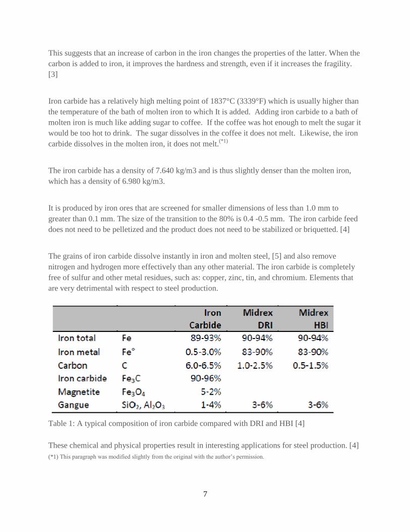
The grains of iron carbide dissolve instantly in iron and molten steel, [5] and also remove
nitrogen and hydrogen more effectively than any other material. The iron carbide is completely
free of sulfur and other metal residues, such as: copper, zinc, tin, and chromium. Elements that
are very detrimental with respect to steel production.
Table 1: A typical composition of iron carbide compared with DRI and HBI [4]
These chemical and physical properties result in interesting applications for steel production. [4]
(*1) This paragraph was modified slightly from the original with the author’s permission.

8
Advantages: Metallurgical and Environmental Benefits:
The iron carbide is much more effective and less expensive than any other means to produce
high-quality steel. [6] a 2004 report by the Department of Energy Technology Roadmap Program
has recognized the iron carbide as the best material for the control of the nitrogen in the
production of steel with EAFs (electric arc furnaces) [7]. Being hard, thick, chemically stable,
granular, manageable and easy to transport. Being dense and heavy, the steelworks can easily
enter it into electric arc furnaces (EAF) using submerged lances. [6]
The iron carbide also offers interesting environmental benefits. The process has lower carbon
emissions than all the working processes of iron-virgin, producing only 1.09 kg of carbon
dioxide CO2 for every kg of steel product. It is significantly lower than the 2.01 kg for the blast
furnace with a conventional BOF furnace (converter to oxygen), 3.09 kg for the coal based DRI
(direct reduction of iron), as Corex, and 1.87 kg for natural gas base DRI, such as Midrex. See
table 2.
Table 2: Carbon Emissions for the Various Processes of Steel Production from Raw Iron. [10]
Only the steels made entirely from scrap reach lower emissions. This is only possible when
producing lower grades of steel and when you use very expensive scrap.
The iron carbide is very effective with respect to protecting the environment by adding it in place
of DRI in electric arc furnace, obtaining only 0.98 kg of CO2 emissions compared to 1.87 kg per
Fastmet (reduction of the iron oxide that produces hot metal with a high purity).
As a further advantage, the iron carbide produces much of the carbon dioxide in a concentrated
stream, which is then easy to sequester and/or use advantageously for other purposes. [6]
9
Iron Carbide for Electric Arc Furnaces
Introduction to Electric Arc Furnaces:
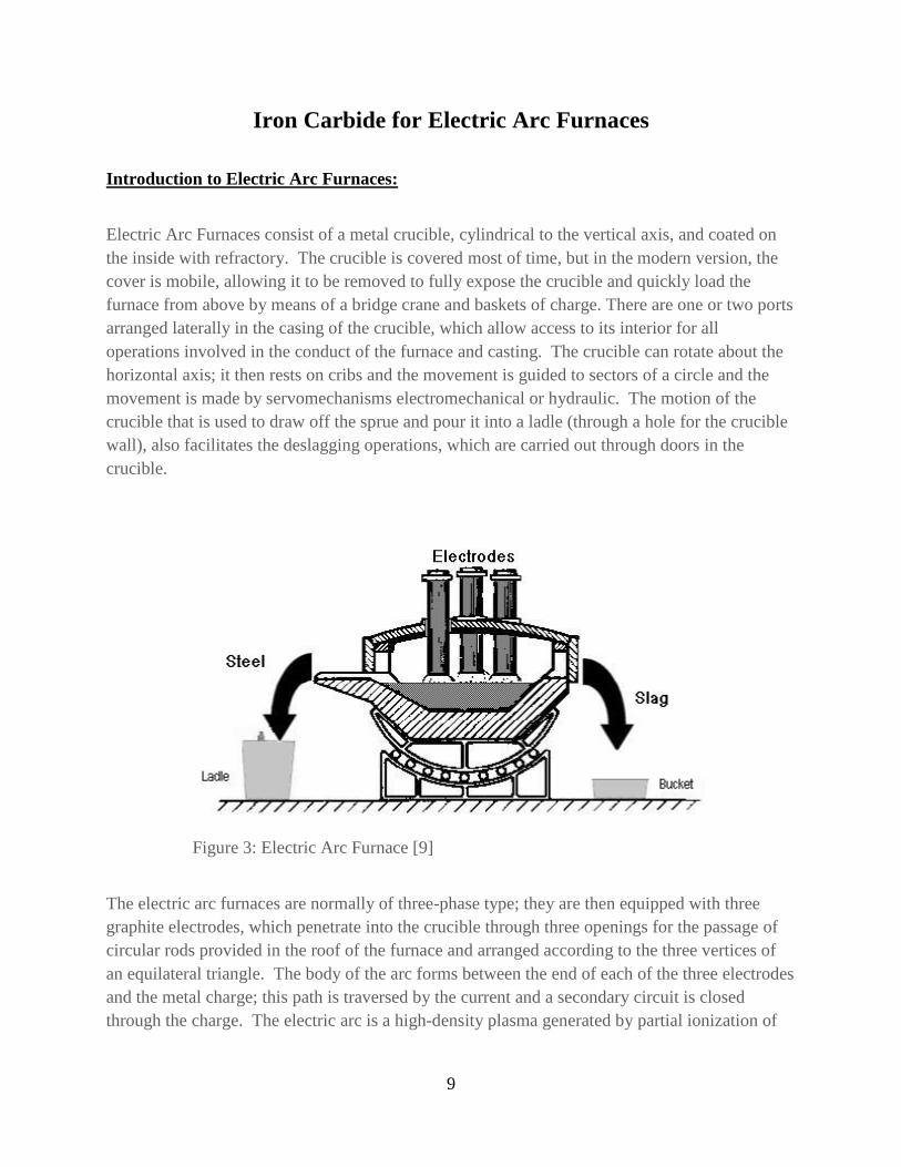
Electric Arc Furnaces consist of a metal crucible, cylindrical to the vertical axis, and coated on
the inside with refractory. The crucible is covered most of time, but in the modern version, the
cover is mobile, allowing it to be removed to fully expose the crucible and quickly load the
furnace from above by means of a bridge crane and baskets of charge. There are one or two ports
arranged laterally in the casing of the crucible, which allow access to its interior for all
operations involved in the conduct of the furnace and casting. The crucible can rotate about the
horizontal axis; it then rests on cribs and the movement is guided to sectors of a circle and the
movement is made by servomechanisms electromechanical or hydraulic. The motion of the
crucible that is used to draw off the sprue and pour it into a ladle (through a hole for the crucible
wall), also facilitates the deslagging operations, which are carried out through doors in the
crucible.
Figure 3: Electric Arc Furnace [9]
The electric arc furnaces are normally of three-phase type; they are then equipped with three
graphite electrodes, which penetrate into the crucible through three openings for the passage of
circular rods provided in the roof of the furnace and arranged according to the three vertices of
an equilateral triangle. The body of the arc forms between the end of each of the three electrodes
and the metal charge; this path is traversed by the current and a secondary circuit is closed
through the charge. The electric arc is a high-density plasma generated by partial ionization of
10
the air and metal vapor coming from the charge; the heat is transmitted to the charge primarily
for irradiation.
A characteristic of the electric arc is to convert into heat a large amount energy within a limited
volume, which allows the furnace to reach high temperatures (in the order of 10,000 °C).
Electricity engaged in supporting of the arc produces the ionization of the medium, and an
increase in the temperature and the conductivity of the medium itself.
Currently, the materials used to charge an electric furnace are of two types: processed iron scrap
and cast iron. The differences between the two are fairly negligible, since the quantity of cast
iron in the charge generally does not exceed the minimum required for achieving the carbon
content that would be required to avoid subsequent refinement. The cast iron in charge rarely
exceeds 10-15% of the total charge. The type of process most widely used is cast iron, given that
this charge is in many circumstances, the more economic. To refine the metal more coke or
anthracite is used.
An interesting filler material for use in electric furnaces is reduced iron ore, in the form of a
sponge, pellets or even briquettes. Today there are some electric steel plants that employ reduced
iron ore on a full industrial scale, and also as a clean source of iron that can be used to dilute and
reduce the concentration of undesirable elements. [9]
Utilization of Iron Carbide in an EAF:
The carbon is essential for the production of steel, and is one of the key elements that improves
the properties of a variety of steel types.
In the past the carbon was loaded into the kiln to ensure that the level of carbon dissolved within
was higher than desired in the final product. As the use of oxygen in the EAF is increasing, the
recent designs tend to require more carbon. The reaction of the carbon with oxygen in the bath
to produce carbon monoxide, leads to a significant increase in energy and has led to substantial
reductions in the consumption of electric energy. The generation of CO is also important for
achieving low concentrations of dissolved gases (nitrogen and hydrogen) in the steel as these are
expelled with the carbon monoxide. The oxide inclusions are eliminated from the steel through
the slag. The carbon dissolved in the steel will react with FeO in the interface between the
slag/bath to produce CO with consequent increase of iron in the bath.
The innovation is in the use of iron carbide, a revolutionary substance for the production of steel.
This new material will have a strong impact in the steel industry during the next decade because
of its exceptional advantages metallurgical, economic and environmental. [10]

11
The iron carbide is ideal for the electric arc furnaces (EAF). It is granular, non-pyrophoric and
dissolves immediately in molten steel. This makes it easy to transport and easy to introduce into
an EAF. [10]
It is free from residual metals and sulfur, contains excess carbon, more than any other reduced
iron product, and the surplus carbon reduces the residual iron oxides, which would otherwise
decrease the yield. [10]
Fig.4: Qualitech Steel inject iron carbide in an EAF to Pittsboro, Indiana, 1998 [10]
Being dense and heavy, the steelworks can easily inject it into an EAF using submerged lances,
like the one that was used in Qualitech Steel’s plant in Pittsboro, Indiana (U.S.A.), shown in
Fig.4. [10]
This is an advantage with respect to DRI, HBI and cast iron. Rates of injection can be reached up
to 2,000 kg/min. After adding the grains of iron carbide into the molten metal bath with gas
injection, which may be nitrogen or air, the gases rises to the surface without reacting in a
substantial way with metal. A separate degassing operation would be slow and expensive,
however, the iron carbide form swarms of bubbles with a different mechanism. [10]
When the iron carbide enters an EAF, it dissolves instantly. Subsequently, the uniformly
dissolved carbon reacts with the small amount of iron oxide that remain in iron carbide product.
The carbon and iron oxide form carbon monoxide. This generates a huge quantity of tiny
bubbles of carbon monoxide, which create the boiling of the metal and rapidly homogenize the
molten metal bath, absorbing nitrogen and hydrogen and creating a foamy slag, which allows for
the removal of the unwanted nitrogen and hydrogen in the steel.

12
To achieve a higher removal of nitrogen and hydrogen, the injection of iron carbide can start as
soon as the EAF has melted enough steel to submerge the lance [11]. The heat of the furnace
does not damage the injection pipe, because the carrier gas adequately cools the lance. The
widespread generation of carbon monoxide bubbles thoroughly mix the bath, avoid temperatures
gradients [10] and remove the nitrogen from the bath. The mixing is more efficient and faster
with the iron carbide, with which the mixing time is one minute, and with the argon, the time is
four minutes. [12]
Furthermore, the foamy slag produced promotes the metallurgical reactions, isolates the molten
metal, improves energy efficiency because it reduce heat losses to the side walls, reduces wear of
the refractory cover and the electrodes.
DRI, HBI and cast iron are unable to provide mixing and reduction of nitrogen and hydrogen.
Studies have shown that the process provides high yields. In some cases, the yield of iron
carbide for the degree of metallization reach 100 %, because the powerful chemical reducing
action of carbon monoxide reduces the iron oxide in the slag, which has been separated from the
molten metal, to iron. This is not the case for scrap or with DRI, where the performance is 92-95 %.
For all these reasons the iron carbide is the best material for the electric arc furnaces.
Steel producers in the United States, Middle East, India and elsewhere, are increasingly
interested in DRI. Scarcity and high cost of the scrap are shifting the focus on to it. In fact, the
graph of figure 5 shows the evolution of the millions of tonnes of scrap exported per year, which
increased by 400% between 2003 and 2008 and with it the price. [10]
Figure 5: Export of scrap in the world during the last few years [13]
This context is preparing the ground for the new use of iron carbide to produce higher-grade
steel, at a lower cost. [10]

13
History of the production processes
The production of iron carbide was designed and developed at Hazen Research, Colorado, using
a closed circuit with a fluidized-bed of iron ore and from gas, containing H2, CO, CO2, CH4 and
water vapor at 600 °C.
Fig.6: Equipment for the laboratory tests used at Hazen Research, Colorado, to assess
and define the parameters for the production of iron carbide. (Photo Frank A. Stephens)
For every tonne of iron carbide, 1.35 tonnes of hematite and 313 m3 of natural gas are required.
It is clear that the steel can be produced directly from iron carbide in both the BOF (basic oxygen
furnace) and in the EAF, with or without the use of hot metal or scrap, with an evident energy
saving due to the behavior of exothermic oxidation reactions.
Prior to 1975, Dr. Frank M. Stephens, Jr. devised a process for the commercial production of
iron carbide as a feedstock for the production of steel. At that time Dr. Stephens was technical
vice president for Hazen Research, Inc. in Golden, Colorado.
After the initial laboratory tests at Hazen Research, Inc. (H. R) Dr. Stephens applied for a patent
and the Patent Office of the United States (US Patent Office) issued "US Patent No. 4,053.301"
on October 11, 1977.

14
In 1985 Dr. Stephens retired from H. R. and at the same time acquired the rights to the patent on
the iron carbide. He formed the company Iron Carbide Development Corporation (ICDC) and
started marketing the process. In 1988, ICDC and Australian company of the PACT Resources,
Pty. Ltd. Joined to form Iron Carbide Holdings, Limited (ICH).
During 1989, ICH produced 310 tonnes of iron carbide at the demonstration plant. The company
sold the product to seven customers and five companies bought the license or the option to use
this technology including: Nucor, North Star Steel, Mitsubishi, Qualitech Steel and Cleveland
Cliffs. [4]
Nucor Corporation:
Nucor Corporation was one of the recipients of iron
carbide of Wundowie demonstration plant. In 1992,
Nucor acquired a license and authorized PLS
Engineering in Denver, Colorado, (now part of the
Harris Group) to build a plant to produce 300,000
tonnes/year of iron carbide and by the end of 1994 the
plant was in operation.
Fig. 7: Transport of iron carbide product from Nucor,1996, from "New Steel". (Photo Frank A.
Stephens)
Nucor selected a plant site at Point Lisas, Trinidad, where it obtained low costs. Nucor started
the construction in 1993, but unfortunately limited the funds to PLS. PLS depleted those funds
before it completed the design of the plant. NUCOR finished the design. In addition, NUCOR
minimized expenses for some of the equipment of the plant, including the heat exchangers.
At the end of September 1994 Nucor started the plant.
The company however had problems with the compressors for the process gas and shutdown
plant, but left the cooling water running. During this period, a technician removed the level
sensors in the columns of the packed tower for recalibration. He informed the control room, so
the alarms for the liquid level were blocked. One of the valves installed on the packed tower,
despite being in a closed position, leaked and the leak went unnoticed for several days. Once
discovered, the Nucor operators drained the column immediately, but the damage had been done.
The water was passed through the pipes and it was mixed with the iron oxide dust and had
severely fouled the heat exchangers.
Nucor spent more than a year attempting to clean the exchangers without success.

15
Fig.8: Nucor System at Point Lisas, Trinidad, 1994 [6]
Other operational problems of the Nucor plant included:
The pipes for the process gas were undersized. This limited the flow of process gas to a
maximum of 65% of design capacity.
The gas seal for the tuyere plate of the fluidized bed reactor broke frequently.
The ore heating system failed from abrasion and Nucor abandoned the ore heating
system. This compromised the chemistry in the reactor and the quality and quantity of
product were further limited.
The collection tank for the scrubber was undersized.
The system for regulating the flow of product through the product cooler was unreliable
and required excessive maintenance.
The pneumatic lift system for the product was unreliable and needed to excessive
maintenance.
The screw feeder that supplied the ore feed to the plant was too small and was supplied
with inadequate packing glands which leaked severely.
Nucor has spent four years working with these problems, but in 1998, the steel prices dropped.
Nucor shutdown the plant in that year and the plant was demolished in 2002. Despite all the
difficulties encountered, Nucor produced 357,712 tons of iron carbide. The production has
shown that the process was valid. Mechanical failures encountered have stressed the importance
of having adequate facilities. [4]

16
Fig.9: Part of the first iron carbide produced in the Nucor plant, Trinidad. (Photo Frank A.
Stephens)
Qualitech Steel:
Qualitech steel made a second attempt to produce iron carbide on a commercial scale in Corpus
Christi, Texas, where Qualitech Steel Corporation built a new plant. Qualitech obtained a license
to produce iron carbide from ICH, but changed the process, when Mitsubishi Corporation funded
the project and wanted to use two reactors and a pipe grid style, process gas distribution system in
the fluidized bed reactor. The Qualitech plant is shown in Figure 10.
Fig.10: Plant Qualitech Steel, Corpus Christi, Texas, 1999 [6]

17
Process Improvements:
In 2010 Frank A. Stephens, the son of Dr. Frank M. Stephens, Jr. acquired the exclusive
ownership of the rights to the iron carbide process. During the early months of 2011, he formed
International Iron Carbide LLC. The company owns the rights to 35 patents. In the last two
years, the company has thoroughly analyzed the problems encountered in Trinidad and Corpus
Christi and has prepared documented solutions, many of these are, however, considered to be
proprietary. Some of the solutions include:
Robust Shell and Tube heat exchangers
Process gas pipes designed to achieve full capacity
Improvements in the design of the fluidized bed reactor and the gas distribution system
that make the reactor more tolerant of plant shutdowns.
A new, dual gas seal design for the tuyere plate in the fluidized bed reactor1.
A Flash Heating System for the ore feed that includes pneumatic transfer of hot material,
minimal solids inventory for fast starts and stops, the elimination of angular offsets to
avoid abrasion and modular construction to facilitate maintenance.
A Scrubber design that is adequate to achieve full capacity.
Simplified product handling that eliminates the lift system for the product entering the
product cooler.
Eductors to move solids instead of mechanical conveyors.
Unfortunately, today, nobody produces iron carbide but International Iron Carbide has learned
from the successes and failures of the two, first generation plants and has developed a design for
a second generation plant that is based on the many lessons learned. International Iron Carbide is
actively searching for clients to build the second-generation plants.
Production Process
Iron carbide is a source of high quality iron for the production of steel in an EAF or BOF. It
offers unsurpassed metallurgical benefits and excellent cost savings. The process generates lower
carbon emissions than any other working process for iron ore.
The manufacturing process is clean and simple. It converts the iron ore to iron carbide in a
fluidized bed reactor, which causes the iron ore to come into contact with process gas consisting
mainly of hydrogen and methane (H2/CH4). The only direct by-product is water generated by the
reduction of the hydrogen and the carbon dioxide from the combustion of natural gas to supply
the process heat.
1 The dual gas seal is used for absolute assurance of sealing the tuyere plate so the process gas
will pass through, and not around, the plate. In fact, if one seal fails, the other seal may allow the
plant to continue to operate until a time that is convenient to repair the failed seal.
18
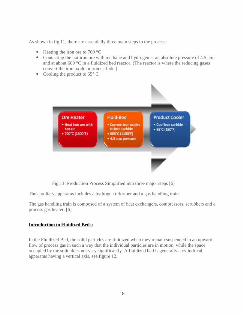
As shown in fig.11, there are essentially three main steps to the process:
Heating the iron ore to 700 °C
Contacting the hot iron ore with methane and hydrogen at an absolute pressure of 4.5 atm
and at about 600 °C in a fluidized bed reactor. (The reactor is where the reducing gases
convert the iron oxide in iron carbide.)
Cooling the product to 65° C
Fig.11: Production Process Simplified into three major steps [6]
The auxiliary apparatus includes a hydrogen reformer and a gas handling train.
The gas handling train is composed of a system of heat exchangers, compressors, scrubbers and a
process gas heater. [6]
Introduction to Fluidized Beds:
In the Fluidized Bed, the solid particles are fluidized when they remain suspended in an upward
flow of process gas in such a way that the individual particles are in motion, while the space
occupied by the solid does not vary significantly. A fluidized bed is generally a cylindrical
apparatus having a vertical axis, see figure 12.

19
Figure 12: Schematic representation of a fluidized bed reactor
Above the gas distributor and bed, is a free zone (or Freeboard) for the disengagement of finer
particles eventually allowing them to fall by gravity from the gas. There may also be dedicated
equipment present for the purpose of gas-solid separation, often consisting of a cyclone placed
outside or inside the unit.
The solids enter the reactor on one side and exit the reactor on the opposite side. To discharge
the reactor, the solids must first fill the bed of the reactor and then overflow through the
discharge port when they are displaced by incoming, fresh iron ore feed material.
One of the most important properties of fluidized beds is their excellent ability to transfer heat,
due to the motion of the solid particles. This property is particularly important when you want to
provide or remove heat from the bed of the reactor. The temperature is homogenized very
quickly and can be generally assumed to be constant within the bed.
To insure proper fluidization, the velocity of the process gas passing through the fluidized bed
reactor must be within a relatively wide range that goes from a minimum value, below which the
particles lie down and no longer move (fixed bed) to a maximum value, above which the
particles are transported with the process gas out of the reactor (pneumatic transport).
The size of the particles that can be fluidized in the process gas stream range from a few
millimeters to a few thousandth of a millimeter, even if the size range most often used is from

20
minus one millimeter (>1.0mm) to plus one, one hundredth millimeter (<0.01mm) the velocity of
the gas is generally between 0.15 and 3.0 meters per second. (*2)
In the fluidized bed reactor the solids are held in suspension by a rising stream of process gas:
this enables the high speed transfer of matter and heat and a good degree of mixing. The solids
can act as a catalyst, a reagent in the chemical process or an inert powder, added to promote the
exchange of heat. [14]
Overview of the Process:
The process converts the iron ore - typically hematite (Fe2O3) or magnetite (Fe3O4) – to iron
carbide (Fe3C), using a gas strongly reducing process gas composed of methane (CH4), hydrogen
(H2), carbon monoxide (CO), carbon dioxide (CO2) and water vapor (H2O).
The process operates at temperatures between 565 °C to 630 °C and at an absolute pressure of
4.5 atm. Overall consumption of natural gas is 313 m3/ton of product. The rated capacity of a
single stage plant operating at 4.5 atmospheres of pressure absolute and 590 °C, is 1,000 tons per
day, or 330.00 tonnes/year with the annual production determined by the number of days of
operation and from the economic tradeoff of the quality of the product with the amount of
product produced.
In the iron carbide product, the unconverted iron is usually present magnetite with smaller
amounts of wustite (FeO) and metallic iron (Fe). For a plant operating with a daily production of
1,000 tons, the quality of the product should be about 90 % of the iron in the form of Fe3C.
The portion of iron converted to iron carbide can be controlled to make the desired product quality, simply
by adjusting the rate of supply of iron to the plant. The product quality that is most useful for the production
of the steel ranges from 85% to 95% of the iron present in the form of iron carbide.
Generally, the iron carbide process does not remove the impurities that are present in the ore, i.e.
components of gangue2, such as the silica (SiO2) and the alumina (Al2O3), which pass
unchanged. Some of the gangue may be removed after the product is cooled, and exposed to a
dry magnetic separator before being sent to storage. If the gangue materials contained in the
product are liberated (if they are not physically bound to the iron compounds), the separator
removes them almost completely.
The only secondary products of the process are carbon dioxide and water vapor. The carbon
dioxide generated by the process is from the combustion of methane or "fuel" for the heating of
the ore and from reforming the natural gas to produce hydrogen. Much of the carbon dioxide is
produced as a by-product from the reformer and is relatively pure. Because it has been produced in
a concentrated stream, it can be easily sequestered and/or advantageously used for other purposes. [6]
2 Gangue refers to the unusable minerals from the original ore deposit that are associated with the useful mineral.
(*2) This paragraph was modified slightly from the original with the author’s knowledge and permission.

21
Fig 13: Diagram of the process for the production of iron carbide [6]
Storage of the Mineral:
The iron ore is usually hematite, which generally contains the 63-65% iron, 1-3% of gangue and
4-10% moisture. The stored ore does not need to be covered, weather permitting. The factors that
influence the decision of whether or not to cover the mineral are the cost of fuel, the contents of
natural moisture and climate.

22
From the ore storage, the ore is transported to a silo or "day bin". The latter stores enough ore to
operate the plant for about 24 hours. A variable speed conveyor measures and controls the
amount of that is fed to the ore heating system. [6]
Heating of the Mineral:
This ore heater is a "Flash Heater" consisting of three cyclones in series. The ore heater heats the
ore up to 710 °C by contacting the ore with the hot oxidizing gas exiting the firebox or "burner".
Increasing the temperature of the iron ore is beneficial to the process. It is beneficial to the
process in the first place, because it removes the moisture from the ore feed, and second because
it oxidizes part of magnetite to hematite. This improves the conversion in the reactor, as hematite
converts faster to iron carbide than magnetite.
The ore heater discharges the hot iron ore into the feed lock hoppers, where it is held before
being fed to the fluidized bed reactor. [6]
Reactor Charging:
The hot ore supply to the reactor is fed via two lock hoppers operating in parallel. The lock
hoppers are lined with refractory material, and have a pyramidal or conical bottom (hopper).
Typically, each hopper feeds the reactor for about one hour and work in such a way that one
hopper is filled, while the other feeds the reactor.
The feeder hoppers also prevent the entry of the oxidizing gases into the reactor. After that the
hot ore is purged with the nitrogen and the pressure is increased, the hot ore is continuously fed
to the reactor at a rate that allows one hopper to empty and to be depressurized before the other
hopper is filled. [6]
Fluidized Bed Reactor:
In the reactor, methane and hydrogen convert the hot iron ore into iron carbide. Oxygen
combines with hydrogen to form water and carbon combines with iron to form iron carbide.
Equation (2), describes the general chemistry:
3 Fe2O3 + 2 CH4 + 5 H2 → 2 Fe3C + 9 H2O (2)
This reaction is a kind of a global summary of all the reactions that take place in the process.
The reaction proceeds in a relatively slow way, and dwell times in the reactor are long in
comparison to the process in the steel making furnace, but this time can be reduced by changing
the temperature and pressure3. One of the advantages of the fluid bed is that uses iron ore fines,
limiting the need for pretreatments such as pelletizing. The ideal feed material is hematite with a
size ranging between 1.0 and 0.1 mm. [15]
3 The specific values are proprietary.

23
One way to evaluate the process (at least in the gaseous phase) is to think of it as formed of only
three basic components: hydrogen, oxygen and carbon.
These three elements interact with each other to form H2, H2O, CO, CO2 and CH4. The
concentration of each of these compounds depends on the ratio of the masses of the individual
elements, the temperature of the system, the system pressure and to some extent the time in
which the elements are in contact. [6]
One of the two main gaseous reactions is described in reaction (3)below and is described as
steam reforming: [16]
CH4 + H2O ↔ CO + 3 H2 (3)
In reaction (3), natural gas reacts with steam to form the hydrogen needed for the process.
The second important gaseous reaction is that of water gas shift, which is described in equation
(4): [16]
CO + H2O ↔ CO2 + H2 (4)
When the reactants are placed all together at a high temperature a gas mixture is obtained containing
H2, H2O, CO, CO2 and CH4. (Of course, will always be a small amount of nitrogen present.)
Figure 14: Summary and simplified of the reactions that occur within the reactor. (Photo Frank
A. Stephens)

24
The gaseous reactions tend to be catalyzed by the presence of metallic iron and/or iron carbide.
The carbon and the hydrogen for the above reactions come from the reagents entered in the
process. The oxygen is extracted from the ore by means of the reaction described in equation (5):
Fe2O3 + 3H2 → 2Fe + 3H2O (5)
By controlling the relative concentrations of hydrogen and carbon in the process gas, it is
possible to promote the removal of oxygen from the ore and the addition of carbon to form iron
carbide.
The reactor, which operates as a dense phase fluidized bed reactor, forms gas bubbles from the
process gas in the fluidized bed. The reactor receives the ore on one side and discharges the
product from the other. The internal baffles convey the solids within the reactor to minimize
short circuiting of the solids and to create a more uniform residence time distribution for the
solids.
Instrumentation continuously monitors the process gas composition, temperature and pressure.
The process produces a non-pyrophoric product, which can then be stored and transported.
The inside diameter of the reactor is about 12 meters and operates at 590° C, receiving process
gas consisting essentially of methane and hydrogen. Hydrogen is introduced to maintain the
pressure in the reactor freeboard at 4.5 atmospheres absolute pressure. The compressors recycle
the process gas to obtain a superficial velocity of 0.92 m/sec.
The retention time of solids is about 16 hours. The reactions to form the iron carbide are slightly
endothermic, so as to maintain the temperature to 590 °C, and necessary to heat the process gas
to 633 °C.
The reactor produces about 42 tonnes/hour of iron carbide product. The product is continuously
discharged through lock hoppers from both the reactor and the off gas cyclones before being
passed through product coolers. [6]
One of the initial process problems was the inadvertent production of free carbon or soot, coming
from the Boudouard reaction (6), which form carbon and carbon dioxide from carbon monoxide:
2 CO ↔ C + CO2 (6)
The International Iron Carbide has however identified process conditions that do not allow the
formation of free carbon, and still producing iron carbide of high quality. The specifics of those
conditions are considered proprietary.
Treatment of the Product:
The reactor discharges the iron carbide product via two lock hoppers (similar to those used to
feed the hot iron ore to the reactor), which release the product to atmospheric pressure. In fact,

25
while one receives the hot product at 3.5 atmospheres of pressure, the other discharges the
product to the cooling device "the Product Cooler" at atmospheric pressure.
The iron carbide exits the lock hoppers at about 587 °C and is cooled to about 65 °C by passing
through the product coolers.
The inventory of product in the product coolers is controlled with a variable speed discharge
conveyor belt that leads the iron carbide to the dry magnetic separator. As described above, the
magnetic separator removes a significant amount of gangue liberated (typically 50 %), which,
however, depends on the iron ore fed to the process.
Gas Treatment System:
The process gas leaves the reactor at 590 °C, passes through four parallel cyclones, (the "reactor
cyclones") which are lined with refractory material, and remove most of the entrained solids
from the exiting process gas.
The fines collected by the cyclones, about 36 tonnes/hour, flow by gravity into a surge bin,
before being recycled to the reactor. Any additional solid pass through a series of lock hoppers
before entering a product cooler, which cools the solids below 65 °C (usually 38 °C), and finally
add the solids to the product from the reactor cooled upstream of the magnetic separator.
The process gas exiting the reactor cyclones and passes through four parallel heat exchangers
(the "process gas heat exchangers") that reduce the temperature to 150 °C
A Venturi scrubber and a packed bed column ("the packed tower") cool the process gas to 28 °C
to remove the water produced in the reactor and remove the remaining fine particles suspended
in the process gas that escaped the cyclones. This ensures that the quantity of fines in the process
gas is low enough to avoid damaging the recycle compressors for process gas.
A small stream or process gas is removed from the recirculating process gas ("the bleed gas")
leaving leaves the top of the packed tower, before entering the recycle gas compressors, to
prevent the accumulation of nitrogen in the circuit. The amount of bleeding depends on the
nitrogen content of the natural gas, the quantity of nitrogen that gets into the system with the hot
iron ore feed that enters the reactor.
The make-up reagent gas, usually consisting of hydrogen and natural gas, enters the recirculating
process prior to the compressors. The pressure in the freeboard of the fluidized bed reactor
determines the exact amount of hydrogen to be introduced into the system. The addition of
natural gas to the process gas is determined by the concentration of methane in the process gas.
Two centrifugal compressors ("the recycle gas compressors"), one operating and one on standby,
recycle the process gas with a pressure of 4.17 atmospheres at the intake and 5.33 atmospheres at
the discharge. The differential pressure across the compressors regulates the flow of process gas
to the reactor.

26
The four gas-gas heat exchangers, which cool the process gas coming from a fluid bed reactor,
heat the process gas coming from the compressors, reaching a temperature of 520 °C. A gas
heater ("the process gas heater") further increases the process temperature to 633 °C, using the
bleed gas and natural gas as fuel. The exhaust gas coming from the heater provides energy to
heat combustion air supplied to the ore heater.
Process Water:
In the process, there are two water cooling systems. One system for direct contact with the
process gas (“the direct contact cooling water"), which provides cooling water to the Venturi
scrubber and the Packed tower, where in these devices the water is directly contacted with the
process gas. The other water cooling system without contact ("the non-contact cooling water ")
provides cooling water to the cooling system of the products ("product coolers"), the "hydrogen
reformer" and other minor heat exchangers in the plant.
The hot water exiting the packed tower returns directly to the contact cooling tower for the
removal of the heat, while the water exiting from Venturi scrubber goes through a basin of
sedimentation ("thickener") first, where it is filtered to remove the solids that are present. [6]

27
Conclusions
The manufacturing process of iron carbide is simple and produces a product with exceptional
metallurgical properties and powerful economic and environmental benefits.
The advantages of iron carbide and its production consist of:
It is the best charge for the EAF and allows the producers of steel to produce high quality
steels more easily and at a lower cost than any other method.
It is the most effective method for the production of steels with a low content of nitrogen
and hydrogen.
It is free of residual metals such as: copper, zinc, tin, chrome, etc…
It is safe and easy to handle:
It is not pyrophoric.
It is a dense, granular powder that dissolves easily in hot steel. Steel producers
can easily inject iron carbide into a BOF and/or an EAF, where it dissolves
instantly.
The process is the most environmentally friendly to produce metallic iron.
The only by-products of the process are water and carbon dioxide, but the carbon
dioxide produced through the full production of the steel is half of that generated
in the furnace using a traditional BOF with the injection of oxygen.
Much of the carbon dioxide exits the reformer in a flow of gas that is
concentrated, which is easy to sequester and/or re-use for other purposes.
The process uses iron ore fines, which are less costly than pellets.
The product does not need to be briquetted.
The process operates at low temperature and is thermally efficient.
The product is free of residuals (including Cu, Ni, Zn, Sn, Cr & S)
The process is a closed loop process that uses 100% of the reagents added.
The process is simple, consisting of a single stage converter, which is easy to control. [6]

28
Bibliography:
[1] Schriftenreihe Der Forschungsgeminschaft Eisenhüttenachlacken, 2000 (FEhS) “Iron and
Steel Slag -Properties and Utilisation-Reports” from 1974-2000, Duisburg, FEhS.
[2] Cavallini M. , "handouts in the Iron and Steel Industry", Rome, 2013.
[3] M. Bahgat, “Technology of Iron Carbide Synthesis”, Central Metallurgical Research and
Development Institute (CMRDI), P.O. Box 87-Helwan, Cairo 11421, Egypt.
[4] Frank A. Stephens and Charles Maxwell, International Iron Carbide LLC, “The 2nd
Generation of Iron Carbide Plants-Compelling Metallurgical, Cost, and Environmental
Advantages to EAF Steelmakers”, Arvada, Colorado.
[5] Gordon H. Geiger, “Injection of Electric Furnace: Transformation from an Energy Source to
a Chemical Reaction” , Keynote lecture at 22nd McMaster Symposium on Enhancement of
EAF Performance by Injection Technology, May 1994, McMaster University, Hamilton,
Ontario, p.4.
[6] International Iron Carbide LLC, “Iron Carbide Manufacturing Process”, Arvada, Colorado,
U.S.A., November 2011.
[7] Donel Anghelina, Geoffrey A. Brooks, and Gordon A. Irons, “Nitrogen Control in EAF
Steelmaking by DRI Fines Injection”, American Iron & Steel Institute and Department of
Energy (AISE/DOE) Technology Roadmap Program, 31 Mar 2004.
[8] Gordon H. Geiger, “Iron Ore to Steel via the Iron Carbide Route: an Analysis of the
Environmental Impacts of the Route”, paper presented at the Internation Symposium on
Global Environmental and Iron and Steel Industry, Beijing, China, 1997.
[9] Cavallini M. , "handouts in the Iron and Steel Industry", Rome, 2003.
[10] International Iron Carbide LLC, “Iron Carbide for Electric Arc Furnaces”, Arvada,
Colorado, U.S.A., December 2011.
[11] Gordon H. Geiger, “The Potential for Use of Iron Carbide as an Electric Furnace Raw
Material”, paper presented at the 16th Advanced Technology Symposium, Iron & Steel 37
Society (ISS-AIME), held at Myrtle Beach, South Carolina, May 1993ù; and Geiger, 22nd
McMaster Symposium.
[12] Gordon, 22nd McMaster Symposium, p.5.
[13] World Steel Association, Steel Statistical Yearbook 2010, page 116.

29
[14] Mazzarotta B. , "Plants in the Process Industry", University of Rome "La Sapienza", Faculty
of Engineering, A. A. 2009-10.
[15] Gordon H. Geiger and Frank A. Stephens, “Steelmaking with Iron Carbide”, Iron Carbide
Holdings, Ltd., Lakewood, Colorado, U.S.A.
[16] Frank M. Stephens, Jr., “The Production and Use of Iron Carbide”, Iron Carbide Holdings,
Ltd., Lakewood, Colorado, U.S.A.
In the preparation of the thesis was consulted the following site: www.iicarbide.com