Embed Size (px)
Citation preview

Product information Ultrasonic
Level measurement in liquids and bulk solids
VEGASON 61
VEGASON 62
VEGASON 63
Document ID: 29023
2
Contents
Ultrasonic - Level measurement in liquids and bulk solids
29
02
3-E
N-1
60
31
2
Contents
1 Measuring principle ............................................................................................................................................................................................... 3
2 Type overview ......................................................................................................................................................................................................... 4
3 Instrument selection .............................................................................................................................................................................................. 5
4 Selection criteria .................................................................................................................................................................................................... 6
5 Housing overview .................................................................................................................................................................................................. 7
6 Mounting ................................................................................................................................................................................................................. 8
7 Electronics - 4 … 20 mA/HART - two-wire ........................................................................................................................................................... 9
8 Electronics - 4 … 20 mA/HART - four-wire ........................................................................................................................................................ 10
9 Electronics-ProfibusPA ....................................................................................................................................................................................11
10 Electronics-FoundationFieldbus ..................................................................................................................................................................... 12
11 Operation ..............................................................................................................................................................................................................13
12 Dimensions ........................................................................................................................................................................................................... 15
Take note of safety instructions for Ex applications
Please note the Ex specific safety information that you can find at www.vega.com and that comes with each instrument. In hazardous areas
you should take note of the appropriate regulations, conformity and type approval certificates of the sensors and power supply units. The sen-
sors must only be operated on intrinsically safe circuits. The permissible electrical values are stated in the certificate.
3
Measuring principle
Ultrasonic - Level measurement in liquids and bulk solids
29
02
3-E
N-1
60
31
2
1 Measuring principle
Measuring principleVEGASON emits short ultrasonic pulses in the direction of the measured medium. These pulses are reflected by the product surface and received back again by the sensor. The measuring instrument calculates the level from the running time of the sound wave and the entered vessel height. The non-contact measuring principle is unaffected by product properties and allows setup and commissioning even without medium.
AdvantagesThe compact design enables a simple installation of the sensor. Since the product properties do not influence the level measurement, setup can also be carried out without medium. The inexpensive, non-contact measuring principle allows wear and maintenance free operation.
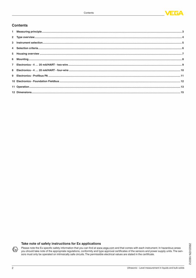
InputvariableThe reference plane for the measurement is the lower edge of the transducer. All statements concerning the measuring range as well as the
internal signal processing refer to this.With all instruments a minimum distance from the lower edge of the flange - the so-called dead band, in which measurement is not possible - must be maintained. You can find the exact value of the dead band in the operating instructions manual of the respective instrument.
3
42
1
Fig. 1: Data of the input variable with VEGASON 63
1 Reference plane
2 Max. measuring range
3 Dead zone
4 Utilisable measuring range
4
Type overview
Ultrasonic - Level measurement in liquids and bulk solids
29
02
3-E
N-1
60
31
2
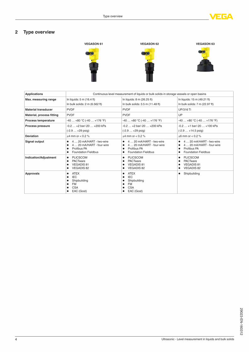
2 Type overview
VEGASON 61 VEGASON 62 VEGASON 63
Applications Continuous level measurement of liquids or bulk solids in storage vessels or open basinsMax. measuring range In liquids: 5 m (16.4 ft)
In bulk solids: 2 m (6.562 ft)In liquids: 8 m (26.25 ft)In bulk solids: 3.5 m (11.48 ft)
In liquids: 15 m (49.21 ft)In bulk solids: 7 m (22.97 ft)
Material transducer PVDF PVDF UP/316 TiMaterial,processfitting PVDF PVDF UP
Process temperature -40 … +80 °C (-40 … +176 °F) -40 … +80 °C (-40 … +176 °F) -40 … +80 °C (-40 … +176 °F)Process pressure -0.2 … +2 bar/-20 … +200 kPa
(-2.9 … +29 psig)-0.2 … +2 bar/-20 … +200 kPa
(-2.9 … +29 psig)-0.2 … +1 bar/-20 … +100 kPa
(-2.9 … +14.5 psig)Deviation ±4 mm or < 0.2 % ±4 mm or < 0.2 % ±6 mm or < 0.2 %
Signal output • 4 … 20 mA/HART - two-wire• 4 … 20 mA/HART - four-wire• Profibus PA• Foundation Fieldbus
• 4 … 20 mA/HART - two-wire• 4 … 20 mA/HART - four-wire• Profibus PA• Foundation Fieldbus
• 4 … 20 mA/HART - two-wire• 4 … 20 mA/HART - four-wire• Profibus PA• Foundation Fieldbus
Indication/Adjustment • PLICSCOM
• PACTware• VEGADIS 81
• VEGADIS 82
• PLICSCOM
• PACTware• VEGADIS 81
• VEGADIS 82
• PLICSCOM
• PACTware• VEGADIS 81
• VEGADIS 82
Approvals • ATEX• IEC
• Shipbuilding
• FM
• CSA
• EAC (Gost)
• ATEX• IEC
• Shipbuilding
• FM
• CSA
• EAC (Gost)
• Shipbuilding
5
Instrument selection
Ultrasonic - Level measurement in liquids and bulk solids
29
02
3-E
N-1
60
31
2
3 Instrument selection
Application areas
The ultrasonic sensors of the VEGASON series are suitable for non-con-
tact level measurement of liquids and bulks solids in simple applications with stable measurement conditions.
VEGASON 61VEGASON 61 is an ultrasonic sensor for continuous level measurement of liquids or bulk solids. Typical applications are the measurement of liquids in storage vessels or open basins. The sensor is also suitable for the detection of bulk solids in small vessels or open containers.
VEGASON 62VEGASON 62 is an ultrasonic sensor for continuous level measurement of liquids or bulk solids. Typical applications are the measurement of liq-
uids in storage vessels or open basins. The sensor is also suitable for the detection of bulk solids in small vessels or silos. Application areas can be found in all industries.
VEGASON 63VEGASON 63 is an ultrasonic sensor for continuous level measure-
ment of liquids or bulk solids. Typical applications are the measurement of liquids in storage vessels or open basins. The sensor is also suitable for continuous level measurement of bulk solids in small vessels up to average-size vessels.
Applications
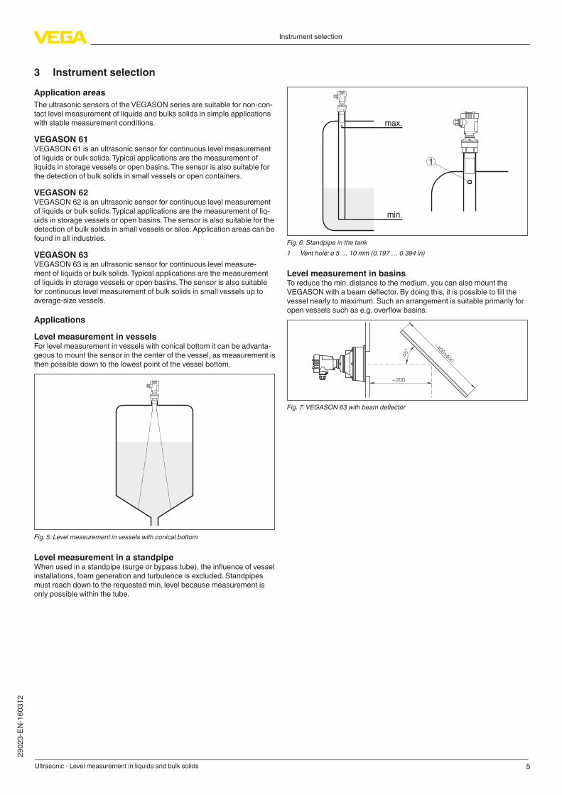
Level measurement in vesselsFor level measurement in vessels with conical bottom it can be advanta-
geous to mount the sensor in the center of the vessel, as measurement is then possible down to the lowest point of the vessel bottom.
Fig. 5: Level measurement in vessels with conical bottom
Level measurement in a standpipeWhen used in a standpipe (surge or bypass tube), the influence of vessel installations, foam generation and turbulence is excluded. Standpipes must reach down to the requested min. level because measurement is
only possible within the tube.
max.
min.
1
Fig. 6: Standpipe in the tank
1 Vent hole: ø 5 … 10 mm (0.197 … 0.394 in)
LevelmeasurementinbasinsTo reduce the min. distance to the medium, you can also mount the VEGASON with a beam deflector. By doing this, it is possible to fill the vessel nearly to maximum. Such an arrangement is suitable primarily for open vessels such as e.g. overflow basins.
~200
~400x4
00
45°
Fig. 7: VEGASON 63 with beam deflector

6
Selection criteria
Ultrasonic - Level measurement in liquids and bulk solids
29
02
3-E
N-1
60
31
2
4 Selection criteria
VEGASON 61 VEGASON 62 VEGASON 63
Vessel Small vessels ● ● ●Average-size vessels – ● ●Open basins ● ● ●
Process Flow measurement ● ● –
Aggressive products ● ● –
Installation Threaded fittings ● ● –
Flange connections ● ● ●Hygienic fittings ● ● –
Mounting strap – – ●Transducer Measurement in a bypass
tube or surge pipe
● ● ●
Suitabilityforindustry-specificapplications
Offshore ● ● ●Shipbuilding ● ● ●Water, waste water ● ● ●
7
Housing overview
Ultrasonic - Level measurement in liquids and bulk solids
29
02
3-E
N-1
60
31
2
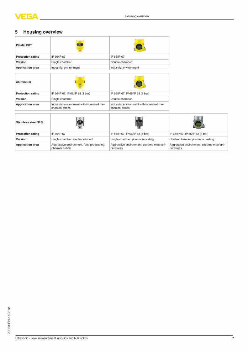
5 Housing overview
Plastic PBT
Protection rating IP 66/IP 67 IP 66/IP 67
Version Single chamber Double chamber
Application area Industrial environment Industrial environment
Aluminium
Protection rating IP 66/IP 67, IP 66/IP 68 (1 bar) IP 66/IP 67, IP 66/IP 68 (1 bar)Version Single chamber Double chamber
Application area Industrial environment with increased me-
chanical stress
Industrial environment with increased me-
chanical stress
Stainless steel 316L
Protection rating IP 66/IP 67 IP 66/IP 67, IP 66/IP 68 (1 bar) IP 66/IP 67, IP 66/IP 68 (1 bar)Version Single chamber, electropolished Single chamber, precision casting Double chamber, precision castingApplication area Aggressive environment, food processing,
pharmaceutical
Aggressive environment, extreme mechani-cal stress
Aggressive environment, extreme mechani-cal stress

8
Mounting
Ultrasonic - Level measurement in liquids and bulk solids
29
02
3-E
N-1
60
31
2
6 Mounting
Mounting examples
The following illustrations show mounting examples and measurement setups.
Waste water tank
Fig. 15: Level measurement in the waste water tank with VEGASON 61
Due to the solid components and the varying density of the tank contents, non-contact level measurement with ultrasonics is the most suitable method here. The PVDF-encapsulated transducer of VEGASON 61 is resistant against aggressive gases in the tank and requires only a G1½ A mounting boss as process fitting.
Pump shaft
Fig. 16: Level measurement in a pump shaft with VEGASON 62
For simple applications in pump shafts, the contactless ultrasonic sensor VEGASON 62 is used. Independent of the waste water consistency it measures the level without maintenance.
Fig. 17: Profile measurement on a conveyor belt with VEGASON 63
The contactlessly measuring ultrasonic sensor VEGASON 63 is an economical solution for profile monitoring, for example of sugar beets. The ultrasonic waves are reflected by the medium, the integrated elec-
tronics determines the loading height of the conveyor belt. By means of the mounting strap, the VEGASON 63 can be optimally oriented to the medium.
9
Electronics - 4 … 20 mA/HART - two-wire
Ultrasonic - Level measurement in liquids and bulk solids
29
02
3-E
N-1
60
31
2
7 Electronics - 4 … 20 mA/HART - two-wire
ConfigurationoftheelectronicsThe plug-in electronics is mounted in the electronics compartment of the instrument and can be exchanged by the user when servicing is required. The electronics is completely encapsulated to protect against vibration and moisture.
The terminals for voltage supply as well as the contact pins with I²C interface for parameter adjustment are located on the upper side of the electronics. In the double-chamber housing, the terminals are located in the separate terminal compartment.
Voltage supply
Depending on the version, the supply voltage and the current signal are carried on the same two-wire connection cable.
The VEGA power supply units VEGATRENN 141/142, VEGASTAB 690 as well as VEGAMET signal conditioning instruments are suitable for power supply. When one of these instruments is used, a reliable separation of the supply circuits from the mains circuits according to DIN VDE 0106 part 101 is ensured for the sensor.• Operating voltage
– 14 … 36 V DC
• Permissible residual ripple
– Upp
< 1 V (< 100 Hz) – U
pp < 10 mV (100 … 10 kHz)
ConnectioncableThe instrument is connected with standard two-wire cable without screen. If electromagnetic interference is expected which is above the test values of EN 61326-1 for industrial areas, screened cable should be used.
We generally recommend the use of screened cable for HART multidrop mode.
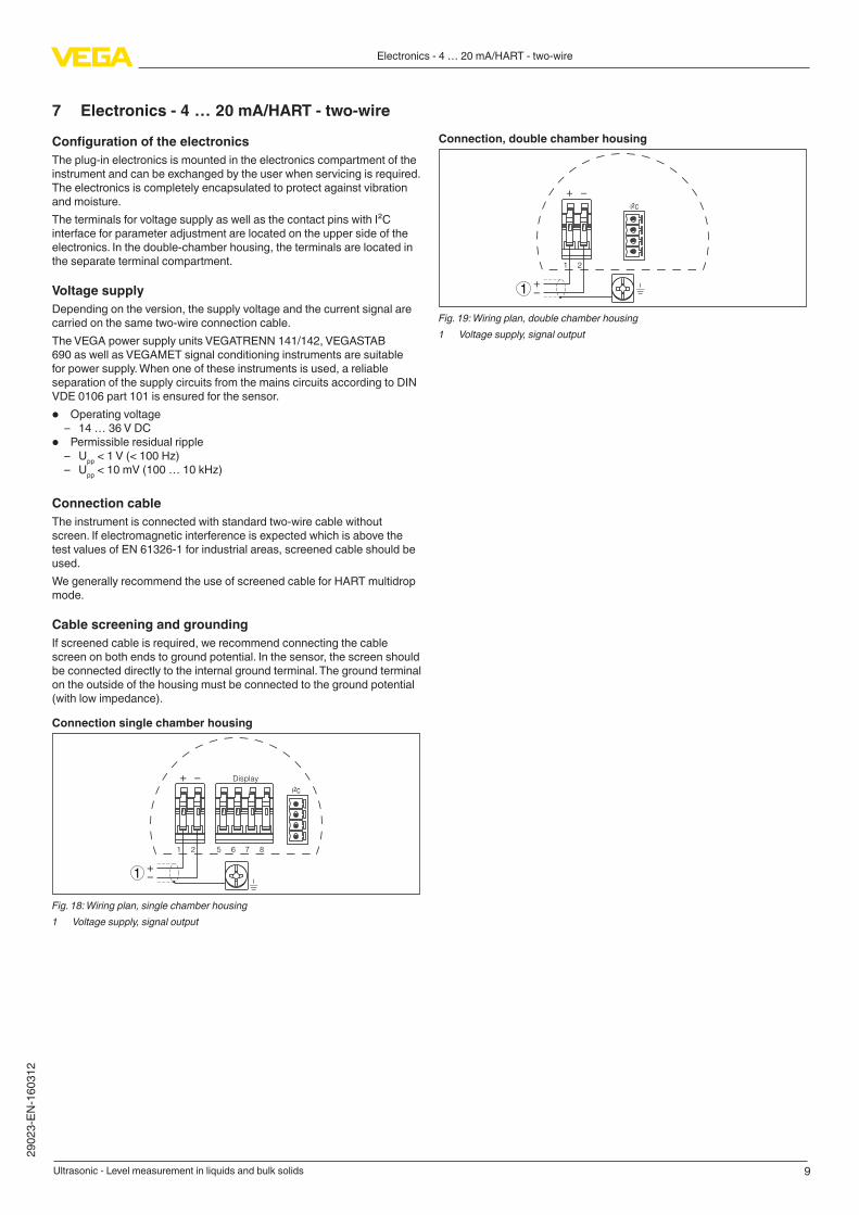
CablescreeningandgroundingIf screened cable is required, we recommend connecting the cable screen on both ends to ground potential. In the sensor, the screen should be connected directly to the internal ground terminal. The ground terminal on the outside of the housing must be connected to the ground potential (with low impedance).Connectionsinglechamberhousing
I2C
Display
1
1 2 5 6 7 8
Fig. 18: Wiring plan, single chamber housing
1 Voltage supply, signal output
Connection,doublechamberhousing
I2C
1
1 2
Fig. 19: Wiring plan, double chamber housing
1 Voltage supply, signal output

10
Electronics - 4 … 20 mA/HART - four-wire
Ultrasonic - Level measurement in liquids and bulk solids
29
02
3-E
N-1
60
31
2
8 Electronics - 4 … 20 mA/HART - four-wire
ConfigurationoftheelectronicsThe plug-in electronics is mounted in the electronics compartment of the instrument and can be exchanged by the user when servicing is required. The electronics is completely encapsulated to protect against vibration and moisture.
The terminals for voltage supply as well as the contact pins with I²C interface for parameter adjustment are located on the upper side of the electronics. In the double-chamber housing, the terminals are located in the separate terminal compartment.
Voltage supply
If a reliable separation is required, the power supply and the current output are transmitted over separate two-wire connection cables.
• Operating voltage
– 20 … 72 V DC, 20 … 253 V AC, 50/60 Hz
ConnectioncableThe 4 … 20 mA current output is connected with standard two-wire cable without screen. If electromagnetic interference is expected which is above the test values of EN 61326 for industrial areas, screened cable should be used.
For power supply, an approved installation cable with PE conductor is required.
CablescreeningandgroundingIf screened cable is required, we recommend connecting the cable screen on both ends to ground potential. In the sensor, the screen should be connected directly to the internal ground terminal. The ground terminal on the outside of the housing must be connected to the ground potential (with low impedance).Connection,doublechamberhousing
4 ... 20 mA
PE
/ L
/ N
L1 N GND
1 2
1 2 3 4
4...20mA IS
Fig. 20: Terminal compartment, double chamber housing
1 Spring-loaded terminals for voltage supply2 4 … 20 mA signal output active
Terminal Function Polarity
1 Voltage supply +/L
2 Voltage supply -/N
3 4 … 20 mA output (active) +
4 4 … 20 mA output (active) +
Functional ground with installa-
tion according to CSA
11
Electronics - Profibus PA
Ultrasonic - Level measurement in liquids and bulk solids
29
02
3-E
N-1
60
31
2
9 Electronics-ProfibusPAConfigurationoftheelectronicsThe plug-in electronics is mounted in the electronics compartment of the instrument and can be exchanged by the user when servicing is required. The electronics is completely encapsulated to protect against vibration and moisture.
The terminals for voltage supply as well as the plug with I²C interface for parameter adjustment are located on the upper side of the electronics. In the double-chamber housing, these connection elements are located in the separate terminal compartment.
Voltage supply
The voltage supply is provided by a Profibus DP /PA segment coupler.Specifications of the voltage supply:• Operating voltage
– 9 … 32 V DC
• Max. number of sensors per DP/PA segment coupler – 32
ConnectioncableConnection is carried out with screened cable according to Profibus specification.Make sure that the entire installation is carried out according to the Profi-
bus specification. In particular, make sure that the bus is terminated with suitable terminating resistors.
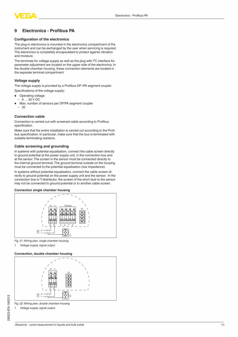
CablescreeningandgroundingIn systems with potential equalisation, connect the cable screen directly to ground potential at the power supply unit, in the connection box and at the sensor. The screen in the sensor must be connected directly to the internal ground terminal. The ground terminal outside on the housing must be connected to the potential equalisation (low impedance).In systems without potential equalisation, connect the cable screen di-rectly to ground potential on the power supply unit and the sensor. In the connection box or T-distributor, the screen of the short stub to the sensor may not be connected to ground potential or to another cable screen.Connectionsinglechamberhousing
I2C
Display
1
1 2 5 6 7 8
Fig. 21: Wiring plan, single chamber housing
1 Voltage supply, signal output
Connection,doublechamberhousing
I2C
1
1 2
Fig. 22: Wiring plan, double chamber housing
1 Voltage supply, signal output
12
Electronics - Foundation Fieldbus
Ultrasonic - Level measurement in liquids and bulk solids
29
02
3-E
N-1
60
31
2
10 Electronics-FoundationFieldbusConfigurationoftheelectronicsThe plug-in electronics is mounted in the electronics compartment of the instrument and can be exchanged by the user when servicing is required. The electronics is completely encapsulated to protect against vibration and moisture.
The terminals for voltage supply as well as the plug with I²C interface for parameter adjustment are located on the upper side of the electronics. In the double-chamber housing, these connection elements are located in the separate terminal compartment.
Voltage supply
Power supply via the H1 Fieldbus cable.Specifications of the voltage supply:• Operating voltage
– 9 … 32 V DC
• max. number of sensors – 32
ConnectioncableConnection is carried out with screened cable according to Fieldbus
specification.Make sure that the entire installation is carried out according to the Field-
bus specification. In particular, make sure that the bus is terminated with suitable terminating resistors.
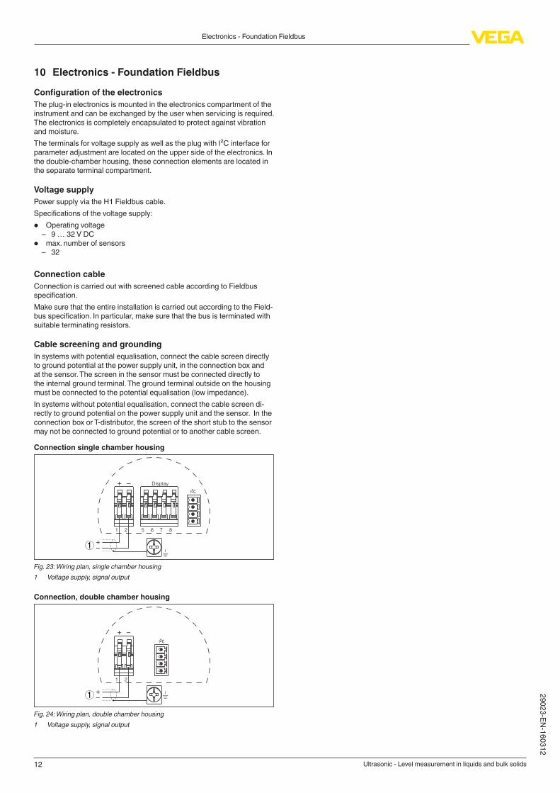
CablescreeningandgroundingIn systems with potential equalisation, connect the cable screen directly to ground potential at the power supply unit, in the connection box and at the sensor. The screen in the sensor must be connected directly to the internal ground terminal. The ground terminal outside on the housing must be connected to the potential equalisation (low impedance).In systems without potential equalisation, connect the cable screen di-rectly to ground potential on the power supply unit and the sensor. In the connection box or T-distributor, the screen of the short stub to the sensor may not be connected to ground potential or to another cable screen.Connectionsinglechamberhousing
I2C
Display
1
1 2 5 6 7 8
Fig. 23: Wiring plan, single chamber housing
1 Voltage supply, signal output
Connection,doublechamberhousing
I2C
1
1 2
Fig. 24: Wiring plan, double chamber housing
1 Voltage supply, signal output
13
Operation
Ultrasonic - Level measurement in liquids and bulk solids
29
02
3-E
N-1
60
31
2
11 Operation
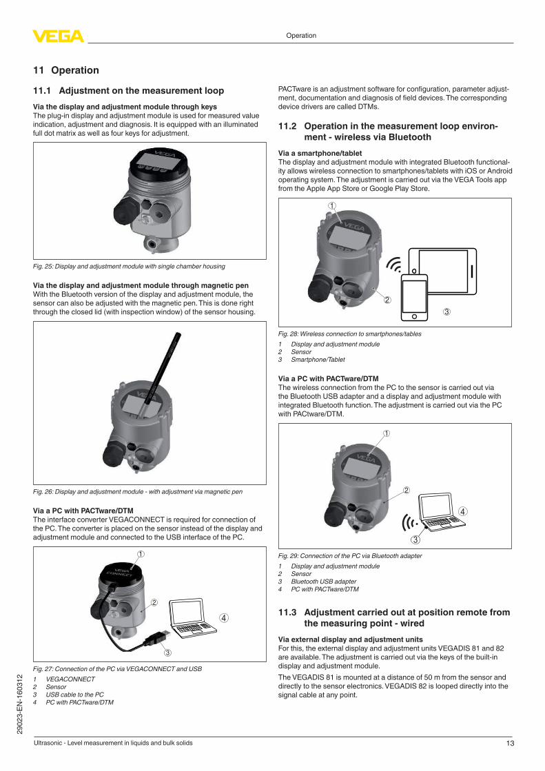
11.1 Adjustment on the measurement loop
Via the display and adjustment module through keys
The plug-in display and adjustment module is used for measured value indication, adjustment and diagnosis. It is equipped with an illuminated full dot matrix as well as four keys for adjustment.
Fig. 25: Display and adjustment module with single chamber housing
Via the display and adjustment module through magnetic pen
With the Bluetooth version of the display and adjustment module, the sensor can also be adjusted with the magnetic pen. This is done right through the closed lid (with inspection window) of the sensor housing.
Fig. 26: Display and adjustment module - with adjustment via magnetic pen
Via a PC with PACTware/DTM
The interface converter VEGACONNECT is required for connection of the PC. The converter is placed on the sensor instead of the display and adjustment module and connected to the USB interface of the PC.
2
3
1
4
Fig. 27: Connection of the PC via VEGACONNECT and USB
1 VEGACONNECT
2 Sensor
3 USB cable to the PC
4 PC with PACTware/DTM
PACTware is an adjustment software for configuration, parameter adjust-ment, documentation and diagnosis of field devices. The corresponding device drivers are called DTMs.
11.2 Operation in the measurement loop environ-
ment - wireless via Bluetooth
Viaasmartphone/tabletThe display and adjustment module with integrated Bluetooth functional-ity allows wireless connection to smartphones/tablets with iOS or Android operating system. The adjustment is carried out via the VEGA Tools app from the Apple App Store or Google Play Store.
1
2
3
Fig. 28: Wireless connection to smartphones/tables
1 Display and adjustment module2 Sensor
3 Smartphone/Tablet
Via a PC with PACTware/DTM
The wireless connection from the PC to the sensor is carried out via the Bluetooth USB adapter and a display and adjustment module with integrated Bluetooth function. The adjustment is carried out via the PC with PACtware/DTM.
2
1
4
3
Fig. 29: Connection of the PC via Bluetooth adapter
1 Display and adjustment module2 Sensor
3 Bluetooth USB adapter
4 PC with PACTware/DTM
11.3 Adjustment carried out at position remote from
the measuring point - wired
Via external display and adjustment units
For this, the external display and adjustment units VEGADIS 81 and 82 are available. The adjustment is carried out via the keys of the built-in display and adjustment module.The VEGADIS 81 is mounted at a distance of 50 m from the sensor and directly to the sensor electronics. VEGADIS 82 is looped directly into the signal cable at any point.

14
Operation
Ultrasonic - Level measurement in liquids and bulk solids
29
02
3-E
N-1
60
31
2
4
1
3
2
5
4
Fig. 30: Connection of VEGADIS 81 to the sensor
1 Voltage supply/Signal output sensor2 Sensor
3 Connection cable sensor - external display and adjustment unit4 External display and adjustment unit5 Display and adjustment module
4
5
3
1
2
Fig. 31: Connection of VEGADIS 82 to the sensor
1 Voltage supply/Signal output sensor2 External display and adjustment unit3 Display and adjustment module4 4 … 20 mA/HART signal cable
5 Sensor
Via a PC with PACTware/DTM
The sensor adjustment is carried out via a PC with PACTware/DTM.
4
5
6
3
2
1
Fig. 32: Connection of VEGADIS 82 to the sensor, adjustment via PC with PACT-
ware
1 Voltage supply/Signal output sensor2 External display and adjustment unit3 VEGACONNECT
4 4 … 20 mA/HART signal cable
5 Sensor
6 PC with PACTware/DTM
11.4 Adjustment carried out at position remote from
themeasuringpoint-wirelessthroughmobilenetwork
As an option, the radio module PLICSMOBILE can be mounted into a plics® sensor with double chamber housing. It is used for transmission of measured values and for remote parameter adjustment of the sensor.
Fig. 33: Transmission of measured values and remote parameter adjustment of the sensor via mobile phone network.
11.5 Alternative adjustment programs
DD adjustment programs
Device descriptions as Enhanced Device Description (EDD) are available for DD adjustment programs such as, for example, AMS™ and PDM.The files can be downloaded at www.vega.com/downloads under "Soft-
ware".
Field Communicator 375, 475
Device descriptions for the instrument are available as EDD for param-
eter adjustment with the Field Communicator 375 or 475.For the integration of the EDD in the Field Communicator 375 or 475, the software "Easy Upgrade Utility" is required which is available from the manufacturer. This software is updated via the Internet and new EDDs are automatically taken over into the device catalogue of this software after they are released by the manufacturer. They can then be transferred to a Field Communicator.
15
Dimensions
Ultrasonic - Level measurement in liquids and bulk solids
29
02
3-E
N-1
60
31
2
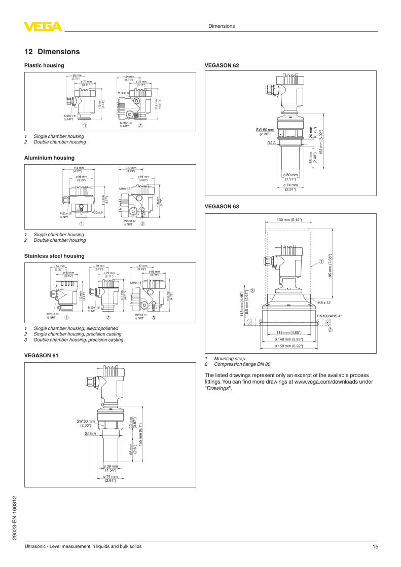
12 Dimensions
Plastic housing
~ 69 mm(2.72")
ø 79 mm(3.11")
11
2 m
m(4
.41
")
M20x1,5/½ NPT
~ 84 mm(3.31")
M16x1,5
11
2 m
m(4
.41
")
M20x1,5/½ NPT1 2
ø 79 mm(3.11")
1 Single chamber housing
2 Double chamber housing
Aluminium housing
21
ø 86 mm
(3.39")
~ 116 mm
(4.57")
11
6 m
m
(4.5
7")
M20x1,5M20x1,5/½ NPT
~ 87 mm(3.43")
M16x1,5
ø 86 mm(3.39")
12
0 m
m(4
.72
")
M20x1,5/½ NPT
1 Single chamber housing
2 Double chamber housing
Stainless steel housing
~ 69 mm(2.72")
ø 79 mm(3.11")
11
7 m
m(4
.61
")
M20x1,5/½ NPT
~ 59 mm(2.32")
ø 80 mm(3.15")
11
2 m
m(4
.41
")
M20x1,5/½ NPT
~ 87 mm(3.43")
ø 86 mm(3.39")
12
0 m
m(4
.72
")
M20x1,5/½ NPT
M16x1,5
321
1 Single chamber housing, electropolished
2 Single chamber housing, precision casting
3 Double chamber housing, precision casting
VEGASON 61
SW 60 mm(2.36")
G1½ A
15
5 m
m (
6.1
")
22
mm
(0.8
7")
66
mm
(2.6
")
ø 39 mm(1.54")
ø 74 mm(2.91")
VEGASON 62
SW 60 mm(2.36")
G2 A
15
3 m
m (
6.0
2")
20
mm
(0.7
9")
63
mm
(2.4
8")
ø 50 mm(1.97")
ø 74 mm(2.91")
VEGASON 63
2
3
1
11
3 m
m (
4.4
5")
11
8,5
mm
(4
.67
")
19
5 m
m (
7.6
8")
ø 148 mm (5.83")
130 mm (5.12")
ø 158 mm (6.22")
118 mm (4.65")
DN100/ANSI4"
M8 x 12
1 Mounting strap
2 Compression flange DN 80
The listed drawings represent only an excerpt of the available process fittings. You can find more drawings at www.vega.com/downloads under
"Drawings".

VEGA Grieshaber KG
Am Hohenstein 113
77761 Schiltach
Germany
2902
3-E
N-1
60312
All statements concerning scope of delivery, application, practical use and operating conditions of the sensors and processing systems correspond to the information
available at the time of printing.
Subject to change without prior notice
© VEGA Grieshaber KG, Schiltach/Germany 2016
Phone +49 7836 50-0
Fax +49 7836 50-201
E-mail: [email protected]
www.vega.com