Embed Size (px)
Citation preview
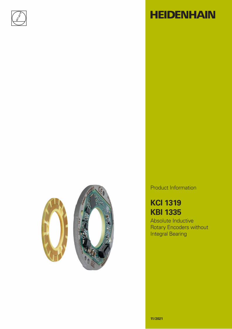
Product Information
KCI 1319KBI 1335Absolute Inductive Rotary Encoders without Integral Bearing
11/2021

0.35 ±0.5
(25.
25)
2 ±0.2
0.35 ±0.56.8 ±0.2
3.3 ±0.2
1.5 ±0.15
(5.3)
0.2 A
0.2 A
0.05 A
4
3.3
±0.
5
43.
3 ±
0.5
3
9 ±
0.3
3
5 ±
0.3
2
5
3
0.5
1.7
21
2
5h6
7.3
1
A
4:1A
A
3x M2
2.35 ±0.3
0.05 A
24.
75
37
2
.4 ±
0.1
± 0.1
Z
3:1Z
A
B
A 0.1 3xB 0.2
C
0.2
B 0.1
A 0.1
0.08 A
(
Z
Z
AE KxI 13xx14.6
± 1.29.8
M3x10 (4x)
Product Information KCI 1319, KBI 1335 11/2021 Product Information KCI 1319, KBI 1335 11/20212 3
KCI 1319, KBI 1335Rotary encoders for absolute position values• Robust inductive scanning principle• Consisting of an AE scanning unit and a rotor unit
= Bearing of mating shaftk = Required mating dimensionsm = Measuring point for operating temperature1 = 15-pin PCB connector2 = M3x10 cylinder head screw (4x)3 = Ensure space for cable4 = Direction of shaft rotation for ascending position values5 = Additional and optional orientation possibility6 = TK/TKN, separate, with different versions possible; for mounting, see the respective dimension drawing7 = Mounting clearance between the circular scale surface and the flange surface;
compensation of mounting tolerances and thermal expansion; dynamic motion permitted over entire range (with use of ATS software for mounting inspection, the display value for the mounting clearance is shown as 1 mm)
8 = Ensure space for electronics; see also the mating dimensions model9 = Flange surface; ensure full-surface contact!10 = Chamfer at start of thread is mandatory for material bonding anti-rotation lock
All drawings with brakes released
= Bearing of mating shaftk = Required mating dimensions1 = AE, separate, with different versions possible (KCI 1319/KBI 1335)2 = Mounting clearance between the circular scale surface and the AE flange surface;
compensation of mounting tolerances and thermal expansion; dynamic motion permitted over entire range
3 = On the fine track ( 35.5 mm to 42.4 mm) after screw-fastening/press-fitting4 = For press-fitting parameters, see the Mounting Instructions5 = Countersunk head screw: M2x6 ISO 14581-A2-70, protrusion of screw head not permitted6 = Distance between AE flange surface and circular scale surface7 = Circular scale surface8 = Use material bonding anti-rotation lock (at least medium strength)
Required mating dimensions for AE KxI 13xx
Rotor fastening via press-fitted hub
Rotor fastening via three axial countersunk head screws
Total height Tolerance
Disk/hub assembly (press-fitted version)
Circular scale (screw-fastened version)
±1.2
Product Information KCI 1319, KBI 1335 11/2021 Product Information KCI 1319, KBI 1335 11/20214 5
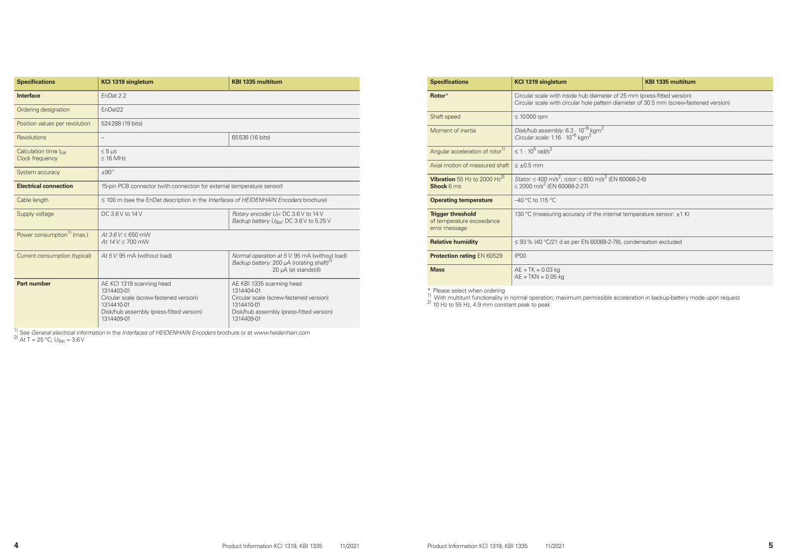
Specifications KCI 1319 singleturn KBI 1335 multiturn
Rotor* Circular scale with inside hub diameter of 25 mm (press-fitted version)Circular scale with circular hole pattern diameter of 30.5 mm (screw-fastened version)
Shaft speed 10 000 rpm
Moment of inertia Disk/hub assembly: 6.3 · 10–6 kgm2
Circular scale: 1.16 · 10–6 kgm2
Angular acceleration of rotor1) 1 · 105 rad/s2
Axial motion of measured shaft ±0.5 mm
Vibration 55 Hz to 2000 Hz2)
Shock 6 msStator: ≤ 400 m/s2; rotor: ≤ 600 m/s2 (EN 60068-2-6)≤ 2000 m/s2 (EN 60068-2-27)
Operating temperature –40 °C to 115 °C
Trigger threshold of temperature exceedance error message
130 °C (measuring accuracy of the internal temperature sensor: ±1 K)
Relative humidity 93 % (40 °C/21 d as per EN 60068-2-78), condensation excluded
Protection rating EN 60529 IP00
Mass AE + TK 0.03 kgAE + TKN 0.05 kg
* Please select when ordering1) With multiturn functionality in normal operation; maximum permissible acceleration in backup-battery mode upon request2) 10 Hz to 55 Hz, 4.9 mm constant peak to peak
Specifications KCI 1319 singleturn KBI 1335 multiturn
Interface EnDat 2.2
Ordering designation EnDat22
Position values per revolution 524 288 (19 bits)
Revolutions – 65 536 (16 bits)
Calculation time tcalClock frequency
≤ 5 µs≤ 16 MHz
System accuracy ±90”
Electrical connection 15-pin PCB connector (with connection for external temperature sensor)
Cable length 100 m (see the EnDat description in the Interfaces of HEIDENHAIN Encoders brochure)
Supply voltage DC 3.6 V to 14 V Rotary encoder UP: DC 3.6 V to 14 VBackup battery UBat: DC 3.6 V to 5.25 V
Power consumption1) (max.) At 3.6 V: ≤ 650 mWAt 14 V: ≤ 700 mW
Current consumption (typical) At 5 V: 95 mA (without load) Normal operation at 5 V: 95 mA (without load)Backup battery: 200 µA (rotating shaft)2)
20 µA (at standstill)
Part number AE KCI 1319 scanning head1314403-01Circular scale (screw-fastened version)1314410-01Disk/hub assembly (press-fitted version)1314409-01
AE KBI 1335 scanning head1314404-01Circular scale (screw-fastened version)1314410-01Disk/hub assembly (press-fitted version)1314409-01
1) See General electrical information in the Interfaces of HEIDENHAIN Encoders brochure or at www.heidenhain.com2) At T = 25 °C; UBat = 3.6 V

Product Information KCI 1319, KBI 1335 11/2021 Product Information KCI 1319, KBI 1335 11/20216 7
The KCI 1319/KBI 1335 is mounted either via screw-fastening of the circular scale or through press-fitting of the disk/hub assembly and mounting of the scanning unit. The disk/hub assembly is thereby either press-fitted onto the shaft, or the circular scale is screw-fastened to the given shaft with three screws. The scanning unit is aligned and mounted via four holes on the customer’s mounting surface.
The following material properties and conditions must be complied with for the customer-side mounting design:
Mating stator Mating shaft
Material Aluminum Steel
Tensile strength Rm ≥ 220 N/mm2 ≥ 600 N/mm2
Yield strength Rp0.2 oryield point Re
– ≥ 400 N/mm2
Shear strength τm 130 N/mm2 ≥ 390 N/mm2
Interface pressure PG ≥ 250 N/mm2 ≥ 660 N/mm2
Modulus of elasticity E (at 20 °C)
70 kN/mm2 to 75 kN/mm2
200 kN/mm2 to 215 kN/mm2
Coefficient of thermal expansion therm(at 20 °C)
≤ 25 · 10–6 K–1 Screw-fastened version:10 · 10–6K–1 to 17 · 10–6K–1
Press-fitted version:10 · 10–6K–1 to 12 · 10–6K–1
Surface roughness RZ ≤ 16 µm
Friction values Mounting surfaces must be clean and free of grease. Use screws and washers from HEIDENHAIN in their condition as delivered.
Tightening procedure Use a signal-emitting torque wrench as per DIN EN ISO 6789, with an accuracy of ±6 %
Mounting temperature 15 °C to 35 °C
Mounting
KCI 1319KBI 1335
Screws Quantity
Screw for fastening the scanning unit
ISO 4762-M3×10-8.8-MKL1) ID 202264-87 10 or 100
Fastening screw for circular scale
ISO 14581-M2×6-A2-702) – –
1) With coating for material bonding anti-rotation lock (for information on use, see the Encoders for Servo Drives brochure)
2) Without anti-rotation lock; use at least a medium-strength material bonding anti-rotation lock
Mounting accessories
ScrewsScrews (fastening screws) are not included in delivery; the M3x10 screw with material bonding anti-rotation lock can be ordered separately.
Mounting aidTo avoid damage to the cable, use the mounting aid to connect and disconnect the cable assembly. Apply pulling force only to the connector of the cable assembly and not to the wires.
ID 1075573-01
For more mounting information and mounting aids, see the Mounting Instructions and the Encoders for Servo Drives brochure. The mounting quality can be inspected with the PWM 21 and the ATS software (see Document 1082415).
The press-fitting process may be performed only once for each disk/hub assembly. For the press-fit, comply with the material properties and conditions for the mating surface stated for proper use in the relevant documents. These requirements must be followed, even when new disk/hub
assemblies are press-fitted onto customer shafts that have already been used. Once the lower limit of the press-fit force has been exceeded, the press-fit force being applied must remain within the specified range for the rest of the procedure until the end position is reached.
����������������������������������������������������������� ���� ���������������� ����������� ��������� �����������������������������
����������������
Product Information KCI 1319, KBI 1335 11/20218
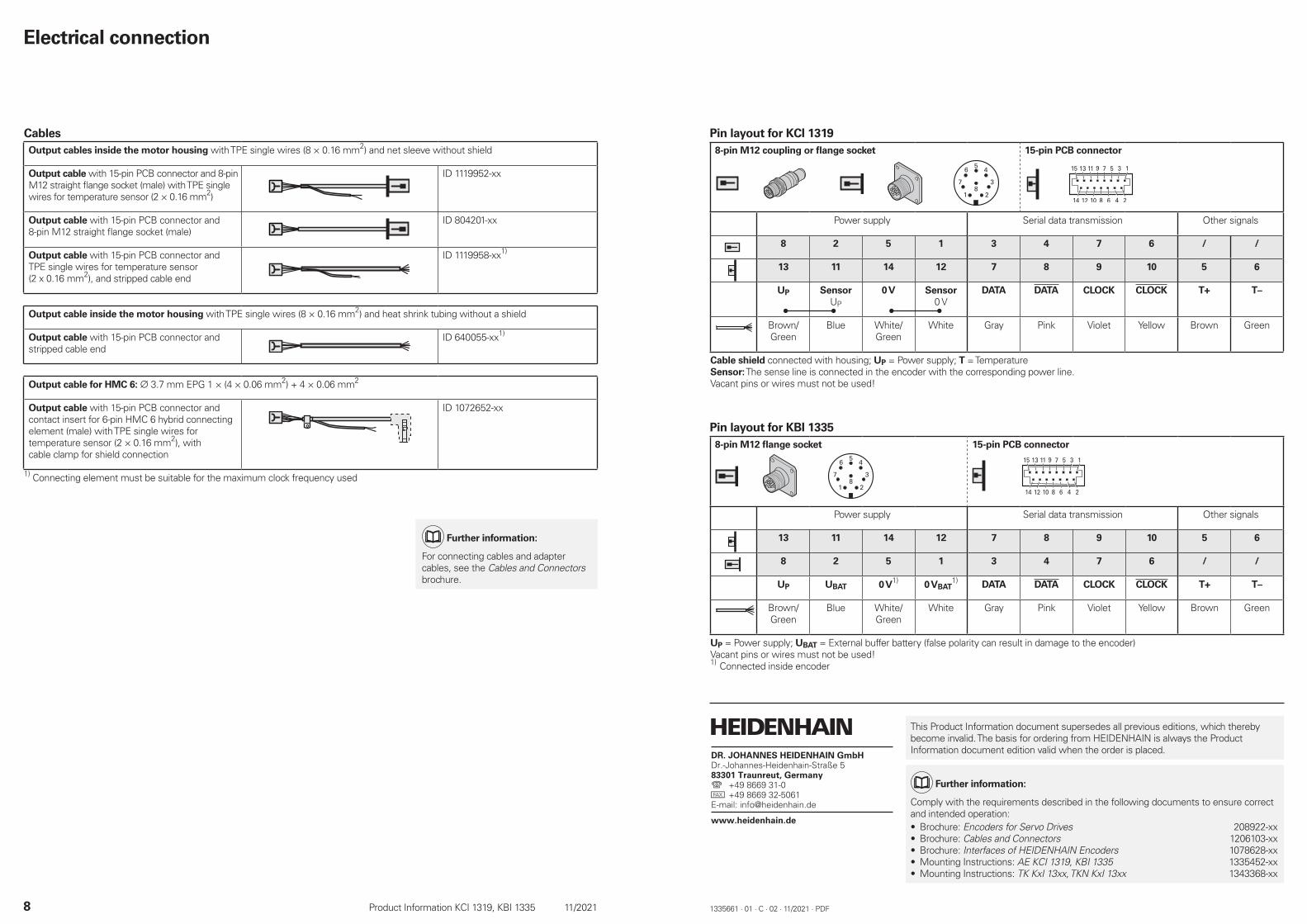
Electrical connection
CablesOutput cables inside the motor housing with TPE single wires (8 × 0.16 mm2) and net sleeve without shield
Output cable with 15-pin PCB connector and 8-pin M12 straight flange socket (male) with TPE single wires for temperature sensor (2 × 0.16 mm2)
ID 1119952-xx
Output cable with 15-pin PCB connector and 8-pin M12 straight flange socket (male)
ID 804201-xx
Output cable with 15-pin PCB connector and TPE single wires for temperature sensor (2 x 0.16 mm2), and stripped cable end
ID 1119958-xx1)
Output cable inside the motor housing with TPE single wires (8 × 0.16 mm2) and heat shrink tubing without a shield
Output cable with 15-pin PCB connector and stripped cable end
ID 640055-xx1)
Output cable for HMC 6: 3.7 mm EPG 1 × (4 × 0.06 mm2) + 4 × 0.06 mm2
Output cable with 15-pin PCB connector and contact insert for 6-pin HMC 6 hybrid connecting element (male) with TPE single wires for temperature sensor (2 × 0.16 mm2), with cable clamp for shield connection
ID 1072652-xx
1) Connecting element must be suitable for the maximum clock frequency used
Pin layout for KCI 13198-pin M12 coupling or flange socket 15-pin PCB connector
Power supply Serial data transmission Other signals
8 2 5 1 3 4 7 6 / /
13 11 14 12 7 8 9 10 5 6
UP SensorUP
0 V Sensor0 V
DATA DATA CLOCK CLOCK T+ T–
Brown/Green
Blue White/Green
White Gray Pink Violet Yellow Brown Green
Cable shield connected with housing; UP = Power supply; T = TemperatureSensor: The sense line is connected in the encoder with the corresponding power line.Vacant pins or wires must not be used!
Pin layout for KBI 13358-pin M12 flange socket 15-pin PCB connector
Power supply Serial data transmission Other signals
13 11 14 12 7 8 9 10 5 6
8 2 5 1 3 4 7 6 / /
UP UBAT 0 V1) 0 VBAT1) DATA DATA CLOCK CLOCK T+ T–
Brown/Green
Blue White/Green
White Gray Pink Violet Yellow Brown Green
UP = Power supply; UBAT = External buffer battery (false polarity can result in damage to the encoder)Vacant pins or wires must not be used!1) Connected inside encoder
1335661 · 01 · C · 02 · 11/2021 · PDF
This Product Information document supersedes all previous editions, which thereby become invalid. The basis for ordering from HEIDENHAIN is always the Product Information document edition valid when the order is placed.
Further information:
Comply with the requirements described in the following documents to ensure correct and intended operation:• Brochure: Encoders for Servo Drives 208922-xx• Brochure: Cables and Connectors 1206103-xx• Brochure: Interfaces of HEIDENHAIN Encoders 1078628-xx• Mounting Instructions: AE KCI 1319, KBI 1335 1335452-xx• Mounting Instructions: TK KxI 13xx, TKN KxI 13xx 1343368-xx
Further information:
For connecting cables and adapter cables, see the Cables and Connectors brochure.