Embed Size (px)
Citation preview

Product Data
123APREFERREDt SERIES 13 AIR CONDITIONERWITH PURONr REFRIGERANT1--1/2 TO 5 NOMINAL TONS (SIZE 018 TO 060)
TM
the environmentally sound refrigerant
Bryant’s Air Conditioners with non--ozone depleting Puronrrefrigerant provide a collection of features unmatched by any otherfamily of equipment.
NOTE: Ratings contained in this document are subject tochange at any time. Always refer to the AHRI directory(www.ahridirectory.org) for the most up--to--date ratingsinformation.
INDUSTRY LEADING FEATURES / BENEFITSEFFICIENCY
S 13 SEER/11 EER
S Microtube Technologyt refrigeration system
S Indoor air quality accessories available
SOUNDS Sound level as low as 70 dBA
COMFORTS System supports Thermidistatt Control or standard
thermostat
RELIABILITYS Non--ozone depleting Puronr refrigerant
S Front--seating service valves
S Scroll compressor
S Internal pressure--relief valve
S Internal thermal overload
S Low--pressure switch
S High--pressure switch
S Filter drier
S Balanced refrigeration system for maximum reliability
DURABILITYDuraGuard Plust protection package:
S Solid, durable sheet metal construction
S Steel louver coil guard
S Baked--on, complete outer coverage, powder paint
APPLICATIONS
S Long--line -- up to 250 feet (76.20 m) total equivalentlength, up to 200 feet (60.96 m) condenser aboveevaporator, or up to 80 ft. (24.38 m) evaporator abovecondenser (See Longline Guide for more information.)
S Low ambient (down to --20_F/--28.9_C) with accessorykit

2
MODEL NUMBER NOMENCLATURE1 2 3 4 5 6 7 8 9 10 11 12 14N N N A A/N N N N N A/N A/N N A
1 2 3 A N A 0 3 6 0 0 0 a
ProductFamily
Tier SEER MajorSeries
Voltage Variations Cooling Capacity Open Open Open MinorSeries
1=AC 2=Preferred
3=13SEER(Nominal)
A=Puron N=208/230---1P = 208/230---3E = 460/3
A = Standard 0=NotDefined
0=NotDefined
0=NotDefined
A =OriginalSeries
This product has been designed and manufactured tomeet Energy Star criteria for energy efficiency whenmatched with appropriate coil components. However,proper refrigerant charge and proper air flow are criticalto achieve rated capacity and efficiency. Installation ofthis product should follow all manufacturing refrigerantcharging and air flow instructions. Failure to confirmproper charge and air flow may reduce energyefficiency and shorten equipment life.
Use of the AHRI CertifiedTM Mark indicates amanufacturer’s participation in the program For verification of certification for individual products, go to www.ahridirectory.org.
STANDARD FEATURESFeature 18 24 30 36 42 48 60
Puron Refrigerant X X X X X X X
13 SEER / 11 EER X X X X X X X
Scroll Compressor X X X X X X X
Louvered Coil Guard X X X X X X X
Field--- Installed Filter Drier X X X X X X X
Front---Seating Service Valves X X X X X X X
Internal Pressure---Relief Valve X X X X X X X
Internal Thermal Overload X X X X X X X
Long Line capability X X X X X X X
Low Ambient capability with Kit X X X X X X X
Low---Pressure Switch X X X X X X X
High---Pressure Switch X X X X X X X
Compressor Sound Blanket X X X X X X X
X = Standard

3
PHYSICAL DATAUNIT SIZE SERIES 18---E 24---E 30---E 36---E 42---C 48---C 60---DCompressor Type ScrollREFRIGERANT Puron (R---410A)Control TXV (Puron Hard Shutoff)
Charge lb (kg) 3.15(1.43)
4.40(2.00)
5.12(2.32)
5.32(2.41)
5.84(2.65)
8.00(3.63)
8.44(3.83)
COND FAN Propeller Type, Direct DriveAir Discharge VerticalAir Qty (CFM) 1792 2196 2196 3700 3170 3365 4050Motor HP 1/12 1/10 1/10 1/4 1/5 1/4 1/4Motor RPM 1100 1100 1100 1100 825 825 825
COND COILFace Area (Sq. ft.) 8.40 9.85 11.49 15.09 17.25 21.56 25.15Fins per In. 20 25 25 25 25 25 25Rows 1 1 1 1 1 1 1Circuits 3 5 3 4 4 5 5
VALVE CONNECT. (In. ID)Vapor 3/4 3/4 3/4 7/8 7/8 7/8 7/8Liquid 3/8
REFRIGERANT TUBES (In. OD)Rated Vapor* 3/4 3/4 3/4 7/8 7/8 7/8 1---1/8Liquid 3/8
*Units are rated with 25 ft (7.6 m) of lineset length. See Vapor Line Sizing and Cooling Capacity Loss table when using other sizes and lengths of lineset.Note: See unit Installation Instruction for proper installation.
OUTDOOR UNIT CONNECTED TO A FACTORY APPROVED INDOOR UNITCheck piston size shipped with indoor unit to see if it matches required indoor piston size. If it does not match, replace indoor piston withcorrect piston size in table below:
OUTDOOR UNIT SIZE --- SERIES FAN COIL PISTON SIZE BY OUTDOOR MODEL018---E FB4CNF* 49024---E FB4CNF* 55030---E FB4CNF* 61036---E FB4CNF* 70042---C FB4CNF* 76048---C FB4CNF* 78
* Ratings contained in this document are subject to change at any time. Always refer to the AHRI directory (www.ahridirectory.org) for the most up---to---dateratings information.
NOTE: Pistons shipped with outdoor units are only qualified and approved with the above listed fan coils. The piston included with the FFMANP* and FPMAN*fan coils are unique to those products and CANNOT be replaced with the piston shipped with outdoor unit. Refer to the AHRI directory(www.ahridirectory.org) to check if your combination can use a piston or requires an accessory TXV.
4
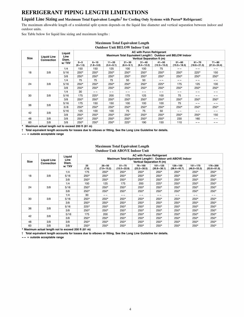
REFRIGERANT PIPING LENGTH LIMITATIONSLiquid Line Sizing and Maximum Total Equivalent Lengths{ for Cooling Only Systems with Puronr Refrigerant:The maximum allowable length of a residential split system depends on the liquid line diameter and vertical separation between indoor andoutdoor units.
See Table below for liquid line sizing and maximum lengths :
Maximum Total Equivalent LengthOutdoor Unit BELOW Indoor Unit
Size Liquid LineConnection
LiquidLineDiam.w/ TXV
AC with Puron RefrigerantMaximum Total Equivalent Length{: Outdoor unit BELOW Indoor
Vertical Separation ft (m)0---5(0---1.5)
6---10(1.8---3.0)
11---20(3.4---6.1)
21---30(6.4---9.1)
31---40(9.4---12.2)
41---50(12.5---15.2)
51---60(15.5---18.3)
61---70(18.6---21.3)
71---80(21.6---24.4)
18 3/81/4 150 150 125 100 100 75 --- --- --- --- --- ---5/16 250* 250* 250* 250* 250* 250* 250* 225* 1503/8 250* 250* 250* 250* 250* 250* 250* 250* 250*
24 3/81/4 75 75 75 50 50 --- --- --- --- --- --- --- ---5/16 250* 250* 250* 250* 250* 225* 175 125 1003/8 250* 250* 250* 250* 250* 250* 250* 250* 250*
30 3/81/4 30 --- --- --- --- --- --- --- --- --- --- --- --- --- --- --- ---5/16 175 225* 200 175 125 100 75 --- --- --- ---3/8 250* 250* 250* 250* 250* 250* 250* 250* 250*
36 3/85/16 175 150 150 100 100 100 75 --- --- --- ---3//8 250* 250* 250* 250* 250* 250* 250* 250* 250*
42 3/85/16 125 100 100 75 75 50 --- --- --- --- --- ---3/8 250* 250* 250* 250* 250* 250* 250* 250* 150
48 3/8 3/8 250* 250* 250* 250* 250* 250* 230 160 --- ---60 3/8 3/8 250* 250* 250* 225* 190 150 110 --- --- --- ---
* Maximum actual length not to exceed 200 ft (61 m){ Total equivalent length accounts for losses due to elbows or fitting. See the Long Line Guideline for details.--- --- = outside acceptable range
Maximum Total Equivalent LengthOutdoor Unit ABOVE Indoor Unit
Size Liquid LineConnection
LiquidLineDiam.w/ TXV
AC with Puron RefrigerantMaximum Total Equivalent Length{: Outdoor unit ABOVE Indoor
Vertical Separation ft (m)25(7.6)
26---50(7.9---15.2)
51---75(15.5---22.9)
76---100(23.2---30.5)
101---125(30.8---38.1)
126---150(38.4---45.7)
151---175(46.0---53.3)
176---200(53.6---61.0)
18 3/81/4 175 250* 250* 250* 250* 250* 250* 250*5/16 250* 250* 250* 250* 250* 250* 250* 250*3/8 250* 250* 250* 250* 250* 250* 250* 250*
24 3/81/4 100 125 175 200 225* 250* 250* 250*5/16 250* 250* 250* 250* 250* 250* 250* 250*3/8 250* 250* 250* 250* 250* 250* 250* 250*
30 3/81/4 30 --- --- --- --- --- --- --- --- --- --- --- --- --- ---5/16 250* 250* 250* 250* 250* 250* 250* 250*3/8 250* 250* 250* 250* 250* 250* 250* 250*
36 3/85/16 225* 250* 250* 250* 250* 250* 250* 250*3/8 250* 250* 250* 250* 250* 250* 250* 250*
42 3/85/16 175 200 250* 250* 250* 250* 250* 250*3/8 250* 250* 250* 250* 250* 250* 250* 250*
48 3/8 3/8 250* 250* 250* 250* 250* 250* 250* 250*60 3/8 3/8 250* 250* 250* 250* 250* 250* 250* 250*
* Maximum actual length not to exceed 200 ft (61 m){ Total equivalent length accounts for losses due to elbows or fitting. See the Long Line Guideline for details.--- --- = outside acceptable range

5
REFRIGERANT CHARGE ADJUSTMENTSLiquid Line Size Puron Charge oz/ft (g/m)
3/8 0.60 (17.74)(Factory charge for lineset = 9 oz / 266.16 g)
5/16 0.40 (11.83)1/4 0.27 (7.98)
Units are factory charged for 15 ft (4.6 m) of 3/8” liquid line. The factory charge for 3/8” lineset 9 oz. When using other length or diameterliquid lines, charge adjustments are required per the chart above.
Charging Formula:
[(Lineset oz/ft x total length) – (factory charge for lineset)] = charge adjustment
Example 1: System has 15 ft of line set using existing 1/4“ liquid line. What charge adjustment is required?
Formula: (.27 oz/ft x 15ft) – (9 oz) = (-4.95) oz.
Net result is to remove 4.95 oz of refrigerant from the system
Example 2: System has 45 ft of existing 5/16” liquid line. What is the charge adjustment?
Formula: (.40 oz/ft. x 45ft) – (9 oz.) = 9 oz.
Net result is to add 9 oz of refrigerant to the system
NOTE: Conditions must be favorable for charging by subcooling method. Indoor temperature must be 70_F to 80_F (21.1_C to 26.7_C),and outdoor temperature must be 70_F to 100_F (21.1_C to 37.8_C). If outside these conditions, adjust charge for long line sets by weigh--inmethod.
LONG LINE APPLICATIONSAn application is considered Long Line, when the refrigerant level in the system requires the use of accessories to maintain acceptablerefrigerant management for systems reliability. See Accessory Usage Guideline table for required accessories. Defining a system as long linedepends on the liquid line diameter, actual length of the tubing, and vertical separation between the indoor and outdoor units.
For Air Conditioner systems, the chart below shows when an application is considered Long Line.
AC with Puronr Refrigerant Long Line Description ft (m) Beyond these lengths, a TXV is required
Total Length Outdoor Unit Above or Below Indoor UnitTXV required beyond 50 ft. (15.2 m) TXV required beyond 20 ft. (6.1 m)
AC with Puronr Refrigerant Long Line Description ft (m) (Beyond these lengths, long line accessories are required)
Liquid Line Size Units On Same Level Outdoor Below Indoor Outdoor Above Indoor
1/4 + TXV No accessories needed within al-lowed lengths
No accessories needed withinallowed lengths 175 (53.3)
5/16 + TXV 120 (36.6) 50 (15.2) vertical or 120 (36.6) total 120 (36.6)3/8 + TXV 80 (24.4) 35 (10.7) vertical or 80 (24.4) total 80 (24.4)
Note: See Residential Piping and Long Line Guideline for details
VAPOR LINE SIZING AND COOLING CAPACITY LOSSAcceptable vapor line diameters provide adequate oil return to the compressor while avoiding excessive capacity loss. The suction linediameters shown in the chart below are acceptable for AC systems with Puron refrigerant:
Vapor Line Sizing and Cooling Capacity Losses — Puronr Refrigerant 1--Stage Air Conditioner Applications
UnitNominalSize (Btuh)
MaximumLiquid LineDiameters(In. OD)
Vapor LineDiameters(In. OD)
Cooling Capacity Loss (%)Total Equivalent Line Length ft. (m)
1---Stage AC with Puron26---50(7.9---15.2)
51---80(15.5---24.4)
81---100(24.7---30.5)
101---125(30.8---38.1)
126---150(38.4---45.7)
151---175(46.0---53.3)
176---200(53.6---61.0)
201---225(61.3---68.6)
226---250(68.9---76.2)
18 3/81/2 1 2 3 5 6 7 8 9 115/8 0 1 1 1 2 2 2 3 33/4 0 0 0 0 1 1 1 1 1
24 3/85/8 0 1 2 2 3 3 4 5 53/4 0 0 1 1 1 1 1 2 27/8 0 0 0 0 0 1 1 1 1
30 3/85/8 1 2 3 3 4 5 6 7 83/4 0 0 1 1 1 2 2 2 37/8 0 0 0 0 1 1 1 1 1
36 3/85/8 1 2 4 5 6 8 9 10 123/4 0 1 1 2 2 3 3 4 47/8 0 0 0 1 1 1 1 2 2
42 3/83/4 0 1 2 2 3 4 4 5 67/8 0 0 1 1 1 2 2 2 31 1/8 0 0 0 0 0 0 0 0 0
48 3/83/4 0 1 2 3 4 5 5 6 77/8 0 0 1 1 2 2 2 3 31 1/8 0 0 0 0 0 0 0 1 1
60 3/83/4 1 2 4 5 6 7 9 10 117/8 0 1 2 2 3 4 4 5 51 1/8 0 0 0 1 1 1 1 1 1
Applications in this area may be long line and may have height restrictions. See the Residential Piping and Long Line Guideline.
6
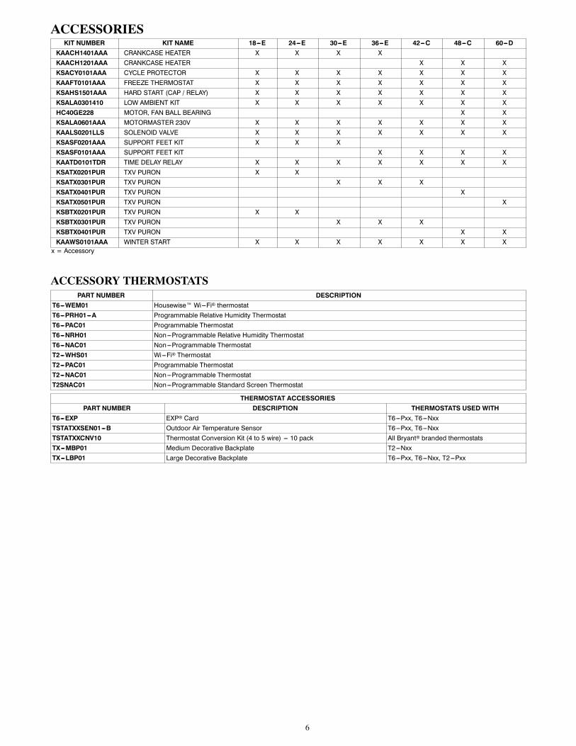
ACCESSORIESKIT NUMBER KIT NAME 18---E 24---E 30---E 36---E 42---C 48---C 60---D
KAACH1401AAA CRANKCASE HEATER X X X XKAACH1201AAA CRANKCASE HEATER X X XKSACY0101AAA CYCLE PROTECTOR X X X X X X XKAAFT0101AAA FREEZE THERMOSTAT X X X X X X XKSAHS1501AAA HARD START (CAP / RELAY) X X X X X X XKSALA0301410 LOW AMBIENT KIT X X X X X X XHC40GE228 MOTOR, FAN BALL BEARING X XKSALA0601AAA MOTORMASTER 230V X X X X X X XKAALS0201LLS SOLENOID VALVE X X X X X X XKSASF0201AAA SUPPORT FEET KIT X X XKSASF0101AAA SUPPORT FEET KIT X X X XKAATD0101TDR TIME DELAY RELAY X X X X X X XKSATX0201PUR TXV PURON X XKSATX0301PUR TXV PURON X X XKSATX0401PUR TXV PURON XKSATX0501PUR TXV PURON XKSBTX0201PUR TXV PURON X XKSBTX0301PUR TXV PURON X X XKSBTX0401PUR TXV PURON X XKAAWS0101AAA WINTER START X X X X X X Xx = Accessory
ACCESSORY THERMOSTATSPART NUMBER DESCRIPTION
T6---WEM01 Housewise Wi---Fi thermostatT6---PRH01---A Programmable Relative Humidity ThermostatT6---PAC01 Programmable ThermostatT6---NRH01 Non---Programmable Relative Humidity ThermostatT6---NAC01 Non---Programmable ThermostatT2---WHS01 Wi---Fi ThermostatT2---PAC01 Programmable ThermostatT2---NAC01 Non---Programmable ThermostatT2SNAC01 Non---Programmable Standard Screen Thermostat
THERMOSTAT ACCESSORIESPART NUMBER DESCRIPTION THERMOSTATS USED WITH
T6---EXP EXP Card T6---Pxx, T6---NxxTSTATXXSEN01---B Outdoor Air Temperature Sensor T6---Pxx, T6---NxxTSTATXXCNV10 Thermostat Conversion Kit (4 to 5 wire) --- 10 pack All Bryant branded thermostatsTX---MBP01 Medium Decorative Backplate T2---NxxTX---LBP01 Large Decorative Backplate T6---Pxx, T6---Nxx, T2---Pxx
7
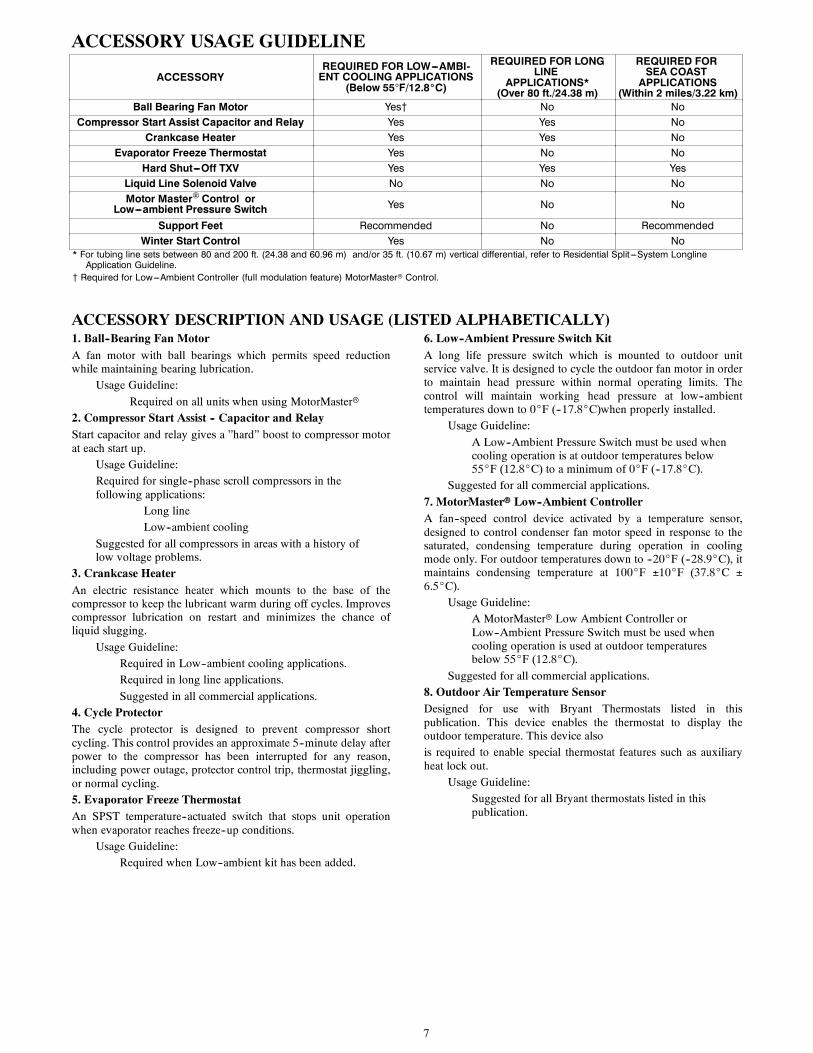
ACCESSORY USAGE GUIDELINE
ACCESSORYREQUIRED FOR LOW---AMBI-ENT COOLING APPLICATIONS
(Below 55F/12.8_C)
REQUIRED FOR LONGLINE
APPLICATIONS*(Over 80 ft./24.38 m)
REQUIRED FORSEA COASTAPPLICATIONS
(Within 2 miles/3.22 km)Ball Bearing Fan Motor Yes{ No No
Compressor Start Assist Capacitor and Relay Yes Yes NoCrankcase Heater Yes Yes No
Evaporator Freeze Thermostat Yes No NoHard Shut---Off TXV Yes Yes Yes
Liquid Line Solenoid Valve No No NoMotor Master Control or
Low---ambient Pressure Switch Yes No No
Support Feet Recommended No RecommendedWinter Start Control Yes No No
* For tubing line sets between 80 and 200 ft. (24.38 and 60.96 m) and/or 35 ft. (10.67 m) vertical differential, refer to Residential Split ---System LonglineApplication Guideline.
{ Required for Low---Ambient Controller (full modulation feature) MotorMasterr Control.
ACCESSORY DESCRIPTION AND USAGE (LISTED ALPHABETICALLY)1. Ball--Bearing Fan MotorA fan motor with ball bearings which permits speed reductionwhile maintaining bearing lubrication.
Usage Guideline:
Required on all units when using MotorMasterr2. Compressor Start Assist -- Capacitor and RelayStart capacitor and relay gives a ”hard” boost to compressor motorat each start up.
Usage Guideline:Required for single--phase scroll compressors in thefollowing applications:
Long lineLow--ambient cooling
Suggested for all compressors in areas with a history oflow voltage problems.
3. Crankcase HeaterAn electric resistance heater which mounts to the base of thecompressor to keep the lubricant warm during off cycles. Improvescompressor lubrication on restart and minimizes the chance ofliquid slugging.
Usage Guideline:Required in Low--ambient cooling applications.Required in long line applications.
Suggested in all commercial applications.4. Cycle ProtectorThe cycle protector is designed to prevent compressor shortcycling. This control provides an approximate 5--minute delay afterpower to the compressor has been interrupted for any reason,including power outage, protector control trip, thermostat jiggling,or normal cycling.5. Evaporator Freeze ThermostatAn SPST temperature--actuated switch that stops unit operationwhen evaporator reaches freeze--up conditions.
Usage Guideline:Required when Low--ambient kit has been added.
6. Low--Ambient Pressure Switch KitA long life pressure switch which is mounted to outdoor unitservice valve. It is designed to cycle the outdoor fan motor in orderto maintain head pressure within normal operating limits. Thecontrol will maintain working head pressure at low--ambienttemperatures down to 0_F (--17.8_C)when properly installed.
Usage Guideline:
A Low--Ambient Pressure Switch must be used whencooling operation is at outdoor temperatures below55_F (12.8_C) to a minimum of 0_F (--17.8_C).
Suggested for all commercial applications.
7. MotorMasterr Low--Ambient ControllerA fan--speed control device activated by a temperature sensor,designed to control condenser fan motor speed in response to thesaturated, condensing temperature during operation in coolingmode only. For outdoor temperatures down to --20_F (--28.9_C), itmaintains condensing temperature at 100_F 10_F (37.8_C 6.5_C).
Usage Guideline:A MotorMasterr Low Ambient Controller orLow--Ambient Pressure Switch must be used whencooling operation is used at outdoor temperaturesbelow 55_F (12.8_C).
Suggested for all commercial applications.8. Outdoor Air Temperature SensorDesigned for use with Bryant Thermostats listed in thispublication. This device enables the thermostat to display theoutdoor temperature. This device alsois required to enable special thermostat features such as auxiliaryheat lock out.
Usage Guideline:Suggested for all Bryant thermostats listed in thispublication.
8
ACCESSORY DESCRIPTION AND USAGE (LISTED ALPHABETICALLY) (CONT)9. Support FeetFour or five astick--on plastic feet that raise the unit 4 in. (101.6mm) above the mounting pad. This allows sand, dirt, and otherdebris to be flushed from the unit base, minimizing corrosion.
Usage Guideline:Suggested in the following applications:Coastal installations.
Windy areas or where debris is normally circulating.Rooftop installations.For improved sound ratings.
10. Thermostatic Expansion Valve (TXV)A modulating flow--control valve which meters refrigerant liquidflow rate into the evaporator in response to the superheat of therefrigerant gas leaving the evaporator.Kit includes valve, adapter tubes, and external equalizer tube. Hardshutoff types are available.NOTE: When using a hard shutoff TXV with single phasereciprocating compressors, a Compressor Start Assist Capacitorand Relay is required.
Usage Guideline:
Accessory required to meet AHRI rating and systemreliability, where indoor not equipped.Hard shutoff TXV or LLS required in air conditionerlong line applications.Required for use on all zoning systems.
11. Time--Delay RelayAn SPST delay relay which briefly continues operation of indoorblower motor to provide additional cooling after the compressorcycles off.
NOTE: Most indoor unit controls include this feature. For thosethat do not, use the guideline below.
Usage Guideline:Accessory required to meet AHRI rating, where indoornot equipped.
12. Winter Start ControlThis control is designed to alleviate nuisance opening of thelow--pressure switch by bypassing it for the first 3 minutes ofoperation.
9
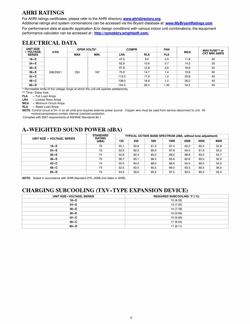
AHRI RATINGSFor AHRI ratings certificates, please refer to the AHRI directory www.ahridirectory.orgAdditional ratings and system combinations can be accessed via the Bryant database at: www.MyBryantRatings.comFor performance data at specific application &/or design conditions with various indoor unit combinations, the equipmentperformance calculator can be accessed at : http://rpmobbry.wrightsoft.com/
ELECTRICAL DATAUNIT SIZE--- VOLTAGE,SERIES
V/PHOPER VOLTS* COMPR FAN
MCA MAX FUSE** orCKT BRK AMPSMAX MIN. LRA RLA FLA
18---E
208/230/1 253 197
47.5 9.0 0.5 11.8 2024---E 62.9 10.9 0.7 14.3 2530---E 67.8 12.8 0.6 16.6 2536---E 75.0 14.7 1.4 19.8 3042---C 112.0 17.9 1.2 23.6 4048---C 109.0 19.9 1.2 26.2 4060---D 134.0 26.4 1.20 34.2 50
* Permissible limits of the voltage range at which the unit will operate satisfactorily.** Time---Delay fuse.FLA --- Full Load AmpsLRA --- Locked Rotor AmpsMCA --- Minimum Circuit AmpsRLA --- Rated Load AmpsNOTE: Control circuit is 24---V on all units and requires external power source. Copper wire must be used from service disconnect to unit. All
motors/compressors contain internal overload protection.Complies with 2007 requirements of ASHRAE Standards 90.1
A--WEIGHTED SOUND POWER (dBA)UNIT SIZE --- VOLTAGE, SERIES
STANDARDRATING(dBA)
TYPICAL OCTAVE BAND SPECTRUM (dBA, without tone adjustment)
125 250 500 1000 2000 4000 8000
18---E 70 50.1 55.6 61.3 67.4 63.2 60.4 52.824---E 72 52.9 62.3 65.0 67.8 64.0 61.9 55.330---E 74 52.8 62.4 65.0 69.2 68.6 63.0 55.736---E 72 58.7 65.1 66.4 65.6 62.6 60.0 52.342---C 74 55.0 64.0 68.0 68.5 64.5 60.0 54.048---C 74 52.5 62.5 65.5 69.0 63.5 60.5 56.060---D 74 54.0 59.0 65.5 67.5 63.5 60.0 55.5
NOTE: Tested in accordance with AHRI Standard 270---2008 (not listed in AHRI).
CHARGING SUBCOOLING (TXV--TYPE EXPANSION DEVICE)UNIT SIZE---VOLTAGE, SERIES REQUIRED SUBCOOLING _F (_C)
18---E 15 (8.33)24---E 13 (7.22)30---E 14 (7.78)36---E 10 (5.56)42---C 10 (5.56)48---C 17 (9.44)60---D 11 (6.11)
10
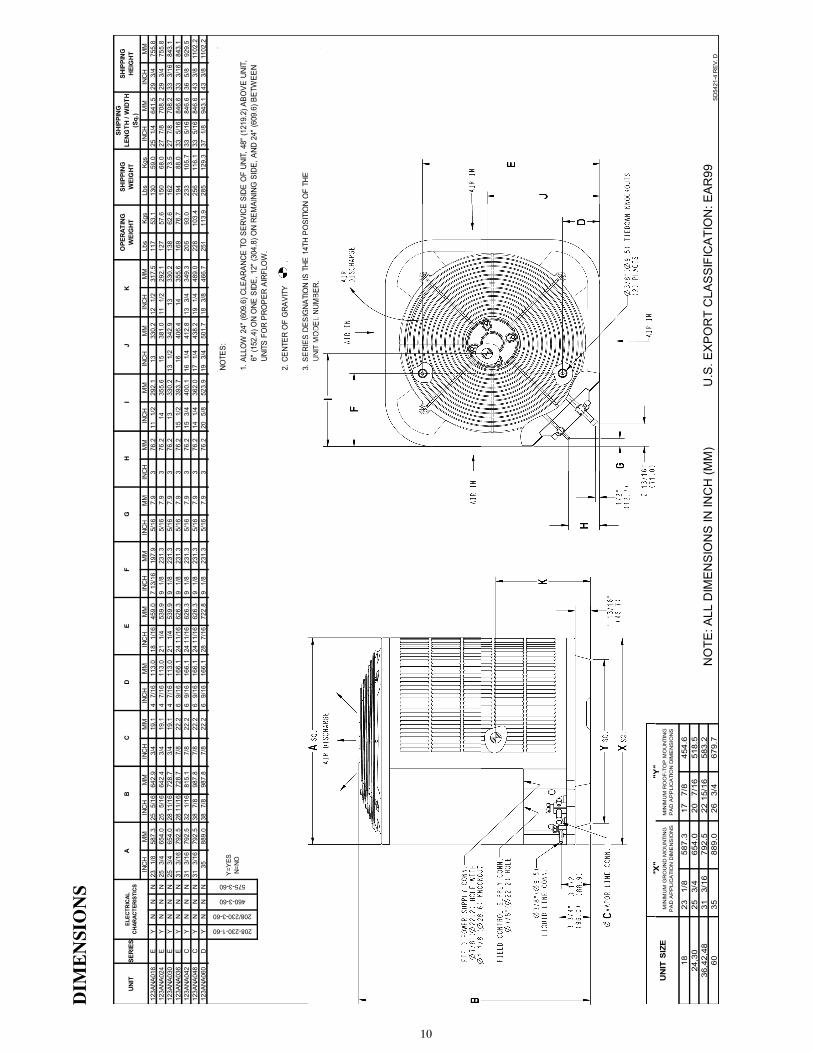
DIM
ENSIONS
INC
HM
MIN
CH
MM
INC
HM
MIN
CH
MM
INC
HM
MIN
CH
MM
INC
HM
MIN
CH
MM
INC
HM
MIN
CH
MM
INC
HM
MLb
sKg
sLb
sKg
sIN
CH
MM
INC
HM
M12
3ANA
018
EY
NN
N23
1/
858
7.3
25
5/16
642.
93/
419
.14
7/16
113.
018
1/
1645
9.0
7 13
/16
197.
95/
167.
93
76.2
11
1/2
292.
113
330.
212
1/
231
7.5
117
53.1
130
59.0
25
1/4
641.
529
3/
475
5.8
123A
NA02
4E
YN
NN
25
3/4
654.
025
5/
1664
2.4
3/4
19.1
4 7/
1611
3.0
21
1/4
539.
99
1/8
231.
35/
167.
93
76.2
1435
5.6
1538
1.0
11
1/2
292.
112
757
.615
068
.027
7/
870
8.2
29
3/4
755.
812
3ANA
030
EY
NN
N25
3/
465
4.0
28 1
1/16
728.
73/
419
.14
7/16
113.
021
1/
453
9.9
9 1/
823
1.3
5/16
7.9
376
.213
330.
213
1/
234
2.9
1333
0.2
138
62.6
162
73.5
27
7/8
708.
233
3/
1684
3.1
123A
NA03
6E
YN
NN
31
3/16
792.
528
11/
1672
8.7
7/8
22.2
6 9/
1616
6.1
24 1
1/16
626.
39
1/8
231.
35/
167.
93
76.2
15
1/2
393.
716
406.
414
355.
616
976
.719
488
.033
5/
1684
6.6
33
3/16
843.
112
3ANA
042
CY
NN
N31
3/
1679
2.5
32
1/16
815.
17/
822
.26
9/16
166.
124
11/
1662
6.3
9 1/
823
1.3
5/16
7.9
376
.215
3/
440
0.1
16
1/4
412.
813
3/
434
9.3
205
93.0
233
105.
733
5/
1684
6.6
36
5/8
929.
512
3ANA
048
CY
NN
N31
3/
1679
2.5
38
7/8
987.
87/
822
.26
9/16
166.
124
11/
1662
6.3
9 1/
823
1.3
5/16
7.9
376
.214
1/
436
2.0
17
1/4
438.
219
1/
448
9.0
228
103.
425
611
6.1
33
5/16
846.
643
3/
811
02.2
123A
NA06
0D
YN
NN
3588
9.0
38
7/8
987.
87/
822
.26
9/16
166.
128
7/
1672
2.8
9 1/
823
1.3
5/16
7.9
376
.220
5/
852
3.9
19
3/4
501.
718
3/
846
6.7
251
113.
928
512
9.3
37
1/8
943.
143
3/
811
02.2
GH
IJ
KU
NIT
SER
IES
ELEC
TRIC
ALC
HAR
ACTE
RIS
TIC
SA
BO
PER
ATIN
GW
EIG
HT
SHIP
PIN
GW
EIG
HT
SHIP
PIN
GLE
NG
TH /
WID
TH
(Sq.
)
U.S
. EX
PO
RT
CLA
SS
IFIC
ATI
ON
: EA
R99
208-230-1-60
208/230-3-60
460-3-60
575-3-60
Y=Y
ESN=
NO
NO
TE: A
LL D
IME
NS
ION
S IN
INC
H (M
M)
C
SD
5421
-4 R
EV.
D
SHIP
PIN
GH
EIG
HT
DE
F
NOTE
S: 1.
ALL
OW
24"
(609
.6) C
LEAR
ANCE
TO
SER
VICE
SID
E O
F UN
IT, 4
8" (1
219.
2) A
BOVE
UNI
T,
6" (
152.
4) O
N O
NE S
IDE,
12"
(304
.8) O
N RE
MAI
NING
SID
E, A
ND 2
4" (6
09.6
) BET
WEE
N
UNI
TS F
OR
PRO
PER
AIRF
LOW
.
2. C
ENTE
R O
F G
RAVI
TY
.
3. S
ERIE
S DE
SIG
NATI
ON
IS T
HE 1
4TH
POSI
TIO
N O
F TH
E
UNI
T M
ODE
L NU
MBE
R.
UN
IT S
IZE
1823
1/
858
7.3
17
7/8
454.
624
,30
25
3/4
654.
020
7/
1651
8.5
36,4
2,48
31
3/16
792.
522
15/
1658
3.2
6035
889.
026
3/
467
9.7
"Y"
MIN
IMU
M R
OO
F-T
OP
MO
UN
TIN
GP
AD
AP
PLI
CA
TIO
N D
IME
NS
ION
S
"X"
MIN
IMU
M G
RO
UN
D M
OU
NTI
NG
PA
D A
PP
LIC
ATI
ON
DIM
EN
SIO
NS
3.SE
RIES
DESI
GNA
TIO
NIS
THE
14TH
POSI
TIO
NO
FTH
EUN
ITM
ODE
LNU
MBE
R.
"Y"
"X"
11
CLEARANCES
Cle
aran
ces
(var
iou
s ex
amp
les)
Wal
l
Wal
l
Wal
l
Wall24
”S
ervi
ce6”
(152
.4 m
m)
24”
(609
.6)
Ser
vice
24”
(609
.6)
Ser
vice
24”
(609
.6)
Ser
vice
24”
(609
.6)
Ser
vice
12”
(304
.8)
12”
(304
.8)
12”
(304
.8)
12”
(304
.8)
6”(1
52.4
)
No
te:
Nu
mb
ers
in (
) =
mm
18”
(457
.2)
18”
(457
.2)
18”
(457
.2)
IMPORTANT:Wheninstallingmultipleunitsinan
alcove,roofwell,orpartially
enclosed
area,ensurethereisadequateventilationtopreventre--circulationofdischargeair.
A07833
12
DETAILEDCOOLINGCAPA
CITIES#
EVAPORATORAIR
CONDENSERENTERINGAIRTEMPERATURES°F(°C)
75(23.9)
85(29.4)
95(35)
105(40.6)
115(46.1)
CFM
EWB
°F(°C)
CapacityMBtuh
TotalSys.
KW**
CapacityMBtuh
TotalSys.
KW**
CapacityMBtuh
TotalSys.
KW**
CapacityMBtuh
TotalSys.
KW**
CapacityMBtuh
TotalSys.
KW**
Total
Sens}
Total
Sens}
Total
Sens}
Total
Sens}
Total
Sens}
123ANA018---EOutdoorSectionWithCNPV*2414AL*IndoorSection
525
72(22.2)
20.77
10.24
1.24
19.95
9.96
1.39
19.07
9.66
1.56
18.09
9.33
1.76
17.01
8.96
1.98
67(19.4)
19.01
12.71
1.25
18.21
12.41
1.40
17.37
12.09
1.57
16.44
11.75
1.77
15.41
11.39
1.99
63(17.2){{
17.69
12.24
1.26
16.91
11.92
1.41
16.09
11.59
1.58
15.20
11.24
1.77
14.20
10.87
1.99
62(16.7)
17.46
15.15
1.26
16.72
14.80
1.41
15.94
14.49
1.58
15.21
15.08
1.77
14.37
14.37
1.99
57(13.9)
17.10
17.10
1.26
16.48
16.48
1.41
15.83
15.83
1.58
15.13
15.13
1.77
14.35
14.35
1.99
600
72(22.2)
21.08
10.74
1.27
20.25
10.46
1.42
19.34
10.15
1.59
18.33
9.82
1.79
17.21
9.44
2.01
67(19.4)
19.30
13.54
1.28
18.49
13.23
1.43
17.60
12.93
1.60
16.62
12.61
1.80
15.59
12.26
2.02
63(17.2)††
17.98
13.01
1.29
17.17
12.69
1.44
16.30
12.38
1.61
15.39
12.06
1.80
14.41
11.65
2.02
62(16.7)
17.85
16.29
1.29
17.23
15.65
1.43
16.51
16.37
1.60
15.71
15.71
1.80
14.88
14.88
2.02
57(13.9)
17.75
17.75
1.29
17.10
17.10
1.44
16.42
16.42
1.61
15.68
15.68
1.80
14.86
14.86
2.02
675
72(22.2)
21.29
11.21
1.29
20.45
10.93
1.45
19.53
10.62
1.62
18.50
10.28
1.82
17.36
9.89
2.04
67(19.4)
19.50
14.36
1.31
18.65
14.08
1.46
17.76
13.80
1.63
16.82
13.42
1.83
15.78
13.00
2.05
63(17.2)††
18.17
13.78
1.32
17.33
13.50
1.47
16.49
13.17
1.64
15.59
12.76
1.83
14.61
12.32
2.05
62(16.7)
18.39
16.74
1.31
17.64
17.64
1.46
16.93
16.93
1.63
16.16
16.16
1.83
15.30
15.30
2.05
57(13.9)
18.28
18.28
1.31
17.61
17.61
1.46
16.90
16.90
1.63
16.14
16.14
1.83
15.28
15.28
2.05
EVAPORATORAIR
CONDENSERENTERINGAIRTEMPERATURES°F(°C)
75(23.9)
85(29.4)
95(35)
105(40.6)
115(46.1)
CFM
EWB
°F(°C)
CapacityMBtuh
TotalSys.
KW**
CapacityMBtuh
TotalSys.
KW**
CapacityMBtuh
TotalSys.
KW**
CapacityMBtuh
TotalSys.
KW**
CapacityMBtuh
TotalSys.
KW**
Total
Sens}
Total
Sens}
Total
Sens}
Total
Sens}
Total
Sens}
123ANA024---EOutdoorSectionWithCNPV*2414AL*IndoorSection
700
72(22.2)
27.25
13.68
1.65
26.06
13.26
1.83
25.42
13.04
2.09
23.78
12.47
2.31
22.10
11.90
2.56
67(19.4)
24.87
16.90
1.65
23.80
16.48
1.84
22.68
16.05
2.05
21.79
15.71
2.37
20.31
15.15
2.59
63(17.2)††
23.14
16.27
1.66
22.14
15.85
1.85
21.09
15.42
2.06
20.07
15.00
2.32
18.78
14.48
2.60
62(16.7)
22.83
20.07
1.66
21.87
19.64
1.85
20.88
19.17
2.06
20.02
19.86
2.32
18.95
18.95
2.59
57(13.9)
22.38
22.38
1.66
21.60
21.60
1.85
20.77
20.77
2.06
20.01
20.01
2.36
18.91
18.91
2.59
800
72(22.2)
27.61
14.35
1.68
26.41
13.93
1.87
25.79
13.72
2.13
24.06
13.14
2.34
22.56
12.63
2.62
67(19.4)
25.26
18.00
1.69
24.16
17.58
1.88
23.00
17.15
2.09
22.12
16.82
2.40
20.57
16.24
2.63
63(17.2)††
23.54
17.31
1.70
22.50
16.88
1.88
21.41
16.44
2.10
20.42
16.03
2.36
19.07
15.49
2.63
62(16.7)
23.36
21.53
1.70
22.54
20.81
1.88
21.55
21.55
2.10
20.72
20.72
2.36
19.62
19.62
2.63
57(13.9)
23.27
23.27
1.70
22.42
22.42
1.88
21.55
21.55
2.10
20.76
20.76
2.41
19.59
19.59
2.63
900
72(22.2)
27.98
15.02
1.72
26.66
14.57
1.91
26.05
14.37
2.16
24.33
13.79
2.39
22.71
13.26
2.66
67(19.4)
25.55
19.06
1.73
24.42
18.64
1.92
23.24
18.20
2.13
22.16
17.79
2.39
20.75
17.25
2.66
63(17.2)††
23.83
18.29
1.74
22.83
17.88
1.92
21.66
17.41
2.13
20.62
16.99
2.40
19.28
16.44
2.67
62(16.7)
24.00
24.00
1.73
23.11
23.11
1.92
22.19
22.19
2.13
21.34
21.34
2.40
20.14
20.14
2.67
57(13.9)
23.97
23.97
1.73
23.08
23.08
1.92
22.13
22.13
2.13
21.30
21.30
2.39
20.13
20.13
2.67
Seenotesonpage15
13
DETAILEDCOOLINGCAPA
CITIES#
CONTINUED
EVAPORATORAIR
CONDENSERENTERINGAIRTEMPERATURES°F(°C)
75(23.9)
85(29.4)
95(35)
105(40.6)
115(46.1)
CFM
EWB
°F(°C)
CapacityMBtuh
TotalSys.
KW**
CapacityMBtuh
TotalSys.
KW**
CapacityMBtuh
TotalSys.
KW**
CapacityMBtuh
TotalSys.
KW**
CapacityMBtuh
TotalSys.
KW**
Total
Sens}
Total
Sens}
Total
Sens}
Total
Sens}
Total
Sens}
123ANA030---EOutdoorSectionWithCNPV*3117AL*IndoorSection
875
72(22.2)
33.50
16.91
2.08
32.19
16.46
2.29
30.70
15.95
2.54
29.03
15.39
2.82
27.46
14.86
3.17
67(19.4)
30.64
21.05
2.08
29.42
20.59
2.29
28.01
20.05
2.53
26.45
19.47
2.81
24.75
18.84
3.13
63(17.2)††
28.61
20.29
2.07
27.42
19.80
2.29
26.06
19.25
2.53
24.61
18.66
2.81
23.01
18.03
3.13
62(16.7)
28.25
25.13
2.07
27.13
24.61
2.29
25.89
25.89
2.53
24.71
24.71
2.81
23.39
23.39
3.13
57(13.9)
27.91
27.91
2.07
26.95
26.95
2.28
25.86
25.86
2.53
24.67
24.67
2.81
23.36
23.36
3.13
1000
72(22.2)
33.97
17.81
2.13
32.58
17.34
2.35
31.07
16.84
2.59
29.34
16.27
2.87
27.74
15.75
3.22
67(19.4)
31.09
22.51
2.13
29.82
22.03
2.34
28.40
21.50
2.58
26.78
20.90
2.86
25.05
20.28
3.19
63(17.2)††
29.06
21.64
2.13
27.84
21.15
2.34
26.45
20.59
2.58
24.94
19.99
2.86
23.30
19.34
3.18
62(16.7)
28.99
28.99
2.12
28.00
28.00
2.34
26.84
26.83
2.58
25.57
25.57
2.86
24.17
24.17
3.18
57(13.9)
29.00
29.00
2.12
27.96
27.96
2.34
26.80
26.80
2.58
25.53
25.53
2.86
24.13
24.13
3.18
1125
72(22.2)
34.31
18.68
2.18
32.86
18.20
2.40
31.31
17.69
2.64
29.56
17.13
2.92
27.93
16.60
3.27
67(19.4)
31.50
23.94
2.18
30.12
23.42
2.39
28.67
22.89
2.63
27.04
22.28
2.91
25.28
21.64
3.25
63(17.2)††
29.40
22.94
2.18
28.16
22.44
2.39
26.73
21.87
2.63
25.20
21.25
2.91
23.53
20.57
3.23
62(16.7)
29.90
29.90
2.18
28.79
28.79
2.39
27.60
27.60
2.63
26.26
26.26
2.91
24.79
24.79
3.24
57(13.9)
29.86
29.86
2.18
28.76
28.76
2.39
27.56
27.56
2.63
26.22
26.22
2.91
24.75
24.75
3.24
EVAPORATORAIR
CONDENSERENTERINGAIRTEMPERATURES°F(°C)
75(23.9)
85(29.4)
95(35)
105(40.6)
115(46.1)
CFM
EWB
°F(°C)
CapacityMBtuh
TotalSys.
KW**
CapacityMBtuh
TotalSys.
KW**
CapacityMBtuh
TotalSys.
KW**
CapacityMBtuh
TotalSys.
KW**
CapacityMBtuh
TotalSys.
KW**
Total
Sens}
Total
Sens}
Total
Sens}
Total
Sens}
Total
Sens}
123ANA036---EOutdoorSectionWithCNPV*3617AL*IndoorSection
1050
72(22.2)
45.00
21.31
2.82
42.27
20.46
2.93
39.43
19.58
3.06
36.45
18.68
3.21
33.29
17.73
3.37
67(19.4)
39.66
26.49
2.80
37.23
25.64
2.91
34.72
24.76
3.04
32.11
23.84
3.18
29.33
22.84
3.36
63(17.2)††
35.73
24.94
2.78
33.45
24.08
2.90
31.18
23.22
3.03
28.80
22.30
3.17
26.25
21.28
3.34
62(16.7)
36.27
36.27
2.78
34.49
34.49
2.90
32.64
32.64
3.03
30.67
30.67
3.18
28.50
28.50
3.35
57(13.9)
36.21
36.21
2.78
34.44
34.44
2.90
32.59
32.59
3.03
30.62
30.62
3.18
28.46
28.46
3.35
1200
72(22.2)
44.13
21.83
3.08
41.23
20.95
3.20
38.29
20.06
3.32
35.19
19.14
3.47
31.92
18.16
3.64
67(19.4)
38.86
27.67
3.06
36.32
26.77
3.18
33.75
25.84
3.30
31.08
24.84
3.45
28.32
23.68
3.62
63(17.2)††
34.85
25.91
3.04
32.54
25.02
3.16
30.20
24.08
3.29
27.79
23.05
3.43
25.60
21.29
3.61
62(16.7)
36.56
36.56
3.05
34.64
34.64
3.17
32.64
32.64
3.30
30.50
30.50
3.44
28.17
28.17
3.62
57(13.9)
36.51
36.51
3.05
34.60
34.60
3.17
32.59
32.59
3.30
30.46
30.46
3.44
28.14
28.14
3.62
1350
72(22.2)
42.95
22.22
3.34
39.98
21.33
3.46
36.93
20.42
3.58
33.75
19.48
3.73
30.38
18.48
3.90
67(19.4)
37.85
28.64
3.32
35.28
27.68
3.44
32.72
26.65
3.56
30.22
25.21
3.71
27.63
27.62
3.88
63(17.2)††
33.87
26.69
3.30
31.51
25.70
3.42
29.29
24.42
3.55
26.98
26.98
3.70
24.61
24.61
3.87
62(16.7)
36.50
36.50
3.31
34.44
34.44
3.43
32.30
32.30
3.56
30.02
30.02
3.71
27.54
27.54
3.88
57(13.9)
36.46
36.46
3.31
34.41
34.41
3.43
32.26
32.26
3.56
29.99
29.99
3.71
27.52
27.52
3.88
Seenotesonpage15
14
DETAILEDCOOLINGCAPA
CITIES#
CONTINUED
EVAPORATORAIR
CONDENSERENTERINGAIRTEMPERATURES°F(°C)
75(23.9)
85(29.4)
95(35)
105(40.6)
115(46.1)
CFM
EWB
°F(°C)
CapacityMBtuh
TotalSys.
KW**
CapacityMBtuh
TotalSys.
KW**
CapacityMBtuh
TotalSys.
KW**
CapacityMBtuh
TotalSys.
KW**
CapacityMBtuh
TotalSys.
KW**
Total
Sens}
Total
Sens}
Total
Sens}
Total
Sens}
Total
Sens}
123ANA042---COutdoorSectionWithCAP**4221AL*IndoorSection
1225
72(22.2)
48.93
25.83
3.05
46.69
24.96
3.36
44.35
24.08
3.73
41.90
23.16
4.17
39.33
22.20
4.68
67(19.4)
44.63
31.68
2.97
42.59
30.82
3.28
40.45
29.92
3.64
38.19
28.99
4.07
35.83
28.03
4.57
63(17.2)††
41.46
30.51
2.93
39.58
29.65
3.23
37.58
28.76
3.59
35.48
27.82
4.00
33.28
26.86
4.49
62(16.7)
40.87
37.50
2.92
39.07
36.62
3.22
37.20
35.70
3.58
35.25
34.67
4.00
33.36
33.36
4.50
57(13.9)
39.83
39.83
2.91
38.36
38.36
3.21
36.79
36.79
3.57
35.10
35.10
4.00
33.31
33.31
4.50
1400
72(22.2)
49.71
26.98
3.13
47.35
26.09
3.45
44.94
25.19
3.82
42.39
24.26
4.26
39.73
23.29
4.77
67(19.4)
45.42
33.57
3.06
43.22
32.66
3.36
41.00
31.75
3.73
38.68
30.82
4.16
36.25
29.84
4.65
63(17.2)††
42.17
32.25
3.01
40.19
31.36
3.31
38.13
30.46
3.67
35.96
29.52
4.09
33.69
28.53
4.58
62(16.7)
41.78
40.06
3.00
39.96
39.11
3.31
38.09
38.09
3.67
36.34
36.34
4.10
34.43
34.43
4.60
57(13.9)
41.35
41.35
3.00
39.77
39.77
3.31
38.10
38.10
3.67
36.29
36.29
4.10
34.39
34.39
4.60
1575
72(22.2)
50.30
28.09
3.21
47.88
27.19
3.53
45.37
26.27
3.91
42.75
25.32
4.35
40.03
24.34
4.86
67(19.4)
45.99
35.38
3.14
43.72
34.46
3.44
41.44
33.55
3.81
39.05
32.60
4.24
36.58
31.60
4.74
63(17.2)††
42.76
33.94
3.09
40.69
33.04
3.39
38.56
32.12
3.75
36.34
31.16
4.17
34.03
30.15
4.66
62(16.7)
42.58
42.58
3.08
40.97
40.97
3.40
39.19
39.17
3.76
37.30
37.30
4.19
35.30
35.30
4.70
57(13.9)
42.60
42.60
3.08
40.92
40.92
3.40
39.15
39.15
3.76
37.26
37.26
4.19
35.26
35.26
4.70
EVAPORATORAIR
CONDENSERENTERINGAIRTEMPERATURES°F(°C)
75(23.9)
85(29.4)
95(35)
105(40.6)
115(46.1)
CFM
EWB
°F(°C)
CapacityMBtuh
TotalSys.
KW**
CapacityMBtuh
TotalSys.
KW**
CapacityMBtuh
TotalSys.
KW**
CapacityMBtuh
TotalSys.
KW**
CapacityMBtuh
TotalSys.
KW**
Total
Sens}
Total
Sens}
Total
Sens}
Total
Sens}
Total
Sens}
123ANA048---COutdoorSectionWithCAP**4821AL*IndoorSection
1400
72(22.2)
54.80
28.81
3.36
52.36
27.89
3.71
49.81
26.94
4.11
47.12
25.95
4.56
44.29
24.93
5.06
67(19.4)
49.76
35.37
3.33
47.53
34.45
3.68
45.17
33.48
4.08
42.70
32.48
4.53
40.10
31.44
5.03
63(17.2)††
46.11
33.99
3.31
44.03
33.06
3.66
41.83
32.09
4.06
39.51
31.08
4.51
37.07
30.04
5.01
62(16.7)
45.39
41.86
3.31
43.42
40.91
3.66
41.35
39.87
4.05
39.18
39.18
4.50
37.29
37.29
5.01
57(13.9)
44.38
44.38
3.30
42.77
42.77
3.65
41.04
41.04
4.05
39.20
39.20
4.50
37.24
37.24
5.01
1650
72(22.2)
55.95
30.53
3.46
53.38
29.59
3.81
50.68
28.61
4.21
47.88
27.60
4.66
44.93
26.56
5.16
67(19.4)
50.81
38.12
3.43
48.46
37.17
3.78
46.00
36.19
4.18
43.42
35.17
4.63
40.74
34.11
5.13
63(17.2)††
47.13
36.55
3.42
44.92
35.59
3.76
42.62
34.60
4.16
40.21
33.58
4.61
37.69
32.50
5.11
62(16.7)
46.71
45.46
3.41
44.79
44.79
3.76
42.93
42.93
4.16
40.95
40.95
4.61
38.84
38.84
5.12
57(13.9)
46.50
46.50
3.41
44.75
44.75
3.76
42.88
42.88
4.16
40.90
40.90
4.61
38.80
38.80
5.12
1800
72(22.2)
56.45
31.49
3.52
53.81
30.54
3.87
51.07
29.55
4.27
48.20
28.54
4.72
45.19
27.47
5.22
67(19.4)
51.28
39.68
3.49
48.88
38.73
3.84
46.37
37.73
4.24
43.75
36.70
4.69
41.02
35.61
5.19
63(17.2)††
47.58
37.99
3.48
45.32
37.03
3.82
42.98
36.03
4.22
40.53
34.98
4.67
37.96
33.87
5.17
62(16.7)
47.62
47.62
3.47
45.78
45.78
3.82
43.84
43.84
4.22
41.78
41.78
4.68
39.59
39.59
5.18
57(13.9)
47.56
47.56
3.47
45.73
45.73
3.82
43.79
43.79
4.22
41.73
41.73
4.68
39.55
39.55
5.18
Seenotesonpage15
15
DETAILEDCOOLINGCAPA
CITIES#
CONTINUED
EVAPORATORAIR
CONDENSERENTERINGAIRTEMPERATURES°F(°C)
75(23.9)
85(29.4)
95(35)
105(40.6)
115(46.1)
CFM
EWB
°F(°C)
CapacityMBtuh
TotalSys.
KW**
CapacityMBtuh
TotalSys.
KW**
CapacityMBtuh
TotalSys.
KW**
CapacityMBtuh
TotalSys.
KW**
CapacityMBtuh
TotalSys.
KW**
Total
Sens}
Total
Sens}
Total
Sens}
Total
Sens}
Total
Sens}
123ANA060---DOutdoorSectionWithCAP**6024AL*IndoorSection
1750
72(22.2)
68.36
36.10
4.29
65.33
34.94
4.72
62.14
33.73
5.20
58.75
32.46
5.75
55.15
31.13
6.37
67(19.4)
62.33
44.29
4.21
59.57
43.11
4.64
56.65
41.89
5.12
53.55
40.62
5.67
50.25
39.28
6.30
63(17.2)††
57.90
42.64
4.16
55.34
41.48
4.58
52.62
40.25
5.06
49.73
38.98
5.61
46.65
37.62
6.25
62(16.7)
57.03
52.36
4.16
54.56
51.17
4.57
51.97
49.89
5.05
49.29
48.49
5.60
46.62
46.62
6.25
57(13.9)
55.44
55.44
4.13
53.46
53.46
4.56
51.33
51.33
5.05
49.04
49.04
5.60
46.55
46.55
6.24
2000
72(22.2)
69.50
37.80
4.40
66.35
36.63
4.83
63.02
35.39
5.31
59.50
34.10
5.86
55.77
32.75
6.48
67(19.4)
63.42
47.04
4.32
60.53
45.85
4.75
57.50
44.61
5.23
54.29
43.31
5.78
50.88
41.95
6.40
63(17.2)††
58.95
45.21
4.27
56.28
44.02
4.69
53.46
42.78
5.17
50.46
41.49
5.72
47.29
40.10
6.36
62(16.7)
58.29
56.06
4.26
55.81
54.75
4.69
53.26
53.26
5.17
50.84
50.84
5.73
48.18
48.18
6.37
57(13.9)
57.63
57.63
4.26
55.50
55.50
4.68
53.22
53.22
5.17
50.77
50.77
5.72
48.13
48.13
6.37
2250
72(22.2)
70.34
39.41
4.51
67.07
38.20
4.94
63.64
36.95
5.42
60.02
35.64
5.97
56.18
34.27
6.59
67(19.4)
64.22
49.65
4.43
61.25
48.45
4.86
58.12
47.19
5.34
54.83
45.87
5.88
51.34
44.46
6.51
63(17.2)††
59.74
47.64
4.38
56.98
46.44
4.80
54.07
45.17
5.28
51.01
43.84
5.83
47.75
42.41
6.46
62(16.7)
59.46
59.46
4.37
57.24
57.24
4.80
54.82
54.82
5.29
52.23
52.23
5.84
49.44
49.44
6.48
57(13.9)
59.43
59.43
4.37
57.17
57.17
4.80
54.76
54.76
5.29
52.15
52.15
5.85
49.39
49.39
6.48
*Testedcombination.
{Totalandsensiblecapacitiesarenetcapacities.Blowermotorheathasbeensubtracted.
}Sensiblecapacitiesshownarebasedon80_F(27_C)enteringairattheindoorcoil.Forsensiblecapacitiesatotherthan80_F(27_C),deduct835Btuh
(245kW)per1000CFM(480L/S)ofindoorcoilairforeachdegreebelow80_F(27_C),oradd835Btuh(245kW)per1000CFM(480L/S)ofindoorcoilairperdegreeabove80_F(27_C).
#DetailedcoolingcapacitiesarebasedonindoorandoutdoorunitatthesameelevationperAHRIstandard210/240---2008.Ifadditionaltubinglengthand/orindoorunitislocatedaboveoutdoorunit,aslightvariationincapacity
mayoccur.
**Systemkwistotalofindoorandoutdoorunitkilowatts.
{{AtTVAratingindoorcondition(75_Fedb/63_Fewb).Allotherindoorairtemperaturesareat80_Fedb.
EWB—EnteringWetBulb
NOTE:Whentherequireddatafallbetweenthepublisheddata,interpolationmaybeperformed.Extrapolationisnotanacceptablepractice.1.

16
CONDENSER ONLY RATINGS*SST° F (° C)
CONDENSER ENTERING AIR TEMPERATURES ° F (° C)55 (12.78) 65 (18.33) 75 (23.89) 85 (29.44) 95 (35.0) 105 (40.56) 115 (46.11)
123ANA018---E
30(---1.11)
TCG 15.90 14.80 13.70 12.80 11.90 10.90 9.90SDT 69.60 78.90 88.30 97.70 107.10 116.40 125.80KW 0.85 0.96 1.09 1.22 1.38 1.55 1.75
35(1.67)
TCG 17.40 16.30 15.20 14.20 13.20 12.20 11.10SDT 70.70 80.00 89.30 98.70 108.00 117.30 126.60KW 0.84 0.96 1.09 1.22 1.38 1.56 1.76
40(4.44)
TCG 19.10 17.90 16.80 15.70 14.60 13.50 12.30SDT 71.80 81.10 90.40 99.70 109.00 118.30 127.50KW 0.83 0.95 1.08 1.22 1.38 1.56 1.76
45(7.22)
TCG 20.80 19.50 18.40 17.30 16.10 14.90 13.60SDT 72.90 82.20 91.50 100.80 110.10 119.30 128.40KW 0.82 0.95 1.08 1.22 1.38 1.56 1.77
50(10.0)
TCG 22.60 21.30 20.10 18.90 17.70 16.40 15.00SDT 74.10 83.40 92.60 101.90 111.10 120.30 129.40KW 0.81 0.94 1.07 1.22 1.38 1.56 1.77
55(12.78)
TCG 24.40 23.10 21.90 20.60 19.30 18.00 16.50SDT 75.40 84.60 93.80 103.10 112.30 121.40 130.40KW 0.80 0.93 1.06 1.21 1.38 1.56 1.77
123ANA024---E
30(---1.11)
TCG 20.90 19.70 18.60 17.50 16.30 15.10 13.80SDT 70.60 79.20 88.70 98.20 107.70 117.90 129.70KW 1.13 1.26 1.41 1.59 1.80 2.05 2.39
35(1.67)
TCG 23.10 21.80 20.60 19.30 18.10 16.80 15.40SDT 71.90 80.40 89.70 99.10 108.60 119.00 127.90KW 1.13 1.26 1.41 1.59 1.80 2.06 2.32
40(4.44)
TCG 25.50 24.10 22.70 21.30 19.90 18.60 17.10SDT 73.60 82.00 90.80 100.10 109.60 119.60 128.80KW 1.13 1.26 1.41 1.59 1.80 2.06 2.32
45(7.22)
TCG 27.90 26.30 24.90 23.40 22.00 20.60 18.90SDT 73.20 82.40 91.80 101.20 110.70 120.80 129.70KW 1.11 1.25 1.41 1.59 1.80 2.06 2.32
50(10.0)
TCG 30.40 28.80 27.20 25.60 24.00 22.60 20.80SDT 74.40 83.70 93.00 102.30 111.70 121.70 130.50KW 1.10 1.24 1.40 1.59 1.80 2.06 2.32
55(12.78)
TCG 33.10 31.30 29.60 27.90 26.20 24.70 22.40SDT 75.60 84.80 94.20 103.40 112.80 122.60 130.90KW 1.09 1.23 1.40 1.58 1.80 2.06 2.30
123ANA030---E
30(---1.11)
TCG 25.50 24.20 22.80 21.50 20.00 18.50 16.90SDT 71.50 80.80 89.50 98.90 108.20 117.50 126.70KW 1.41 1.58 1.75 1.96 2.18 2.45 2.74
35(1.67)
TCG 28.20 26.70 25.20 23.70 22.10 20.50 18.70SDT 73.60 82.10 90.70 100.00 109.30 118.50 127.70KW 1.43 1.59 1.76 1.96 2.19 2.46 2.76
40(4.44)
TCG 30.90 29.30 27.70 26.00 24.30 22.50 20.60SDT 73.80 83.10 92.20 101.20 110.40 119.50 128.80KW 1.41 1.58 1.76 1.97 2.20 2.46 2.78
45(7.22)
TCG 33.70 32.10 30.30 28.60 26.70 24.70 22.60SDT 75.10 84.50 93.40 102.50 111.60 120.70 129.90KW 1.41 1.58 1.76 1.97 2.21 2.47 2.79
50(10.0)
TCG 36.90 35.10 33.20 31.20 29.20 27.00 24.70SDT 76.70 85.80 94.80 103.90 112.90 121.90 131.00KW 1.42 1.59 1.77 1.98 2.22 2.48 2.80
55(12.78)
TCG 40.30 38.30 36.20 34.00 31.80 29.50 27.40SDT 78.40 87.40 96.30 105.30 114.20 123.10 132.60KW 1.43 1.59 1.78 1.99 2.22 2.50 2.83
See notes on page 18

17
CONDENSER ONLY RATINGS CONTINUEDSST° F (° C)
CONDENSER ENTERING AIR TEMPERATURES ° F (° C)55 (12.78) 65 (18.33) 75 (23.89) 85 (29.44) 95 (35.0) 105 (40.56) 115 (46.11)
123ANA036---E
30(---1.11)
TCG 32.60 30.50 28.70 27.00 25.20 23.40 21.50SDT 73.10 82.60 91.10 100.30 109.70 119.00 128.30KW 1.61 1.88 2.11 2.36 2.63 2.95 3.32
35(1.67)
TCG 36.10 33.90 31.80 29.90 27.90 26.00 23.90SDT 74.30 83.90 92.40 101.60 110.80 120.00 129.20KW 1.61 1.90 2.13 2.38 2.65 2.96 3.34
40(4.44)
TCG 40.10 37.60 35.30 33.10 30.90 28.70 26.40SDT 76.00 85.10 93.90 102.90 112.10 121.20 130.30KW 1.64 1.91 2.16 2.41 2.68 2.99 3.36
45(7.22)
TCG 44.50 41.70 39.20 36.70 34.30 31.80 29.30SDT 77.80 86.60 95.60 104.40 113.40 122.40 131.40KW 1.69 1.95 2.19 2.44 2.71 3.02 3.38
50(10.0)
TCG 49.40 46.30 43.50 40.70 38.00 35.20 32.40SDT 79.70 88.50 97.30 106.10 114.90 123.80 132.70KW 1.74 2.00 2.24 2.48 2.75 3.06 3.42
55(12.78)
TCG 54.80 51.40 48.20 45.10 42.00 39.00 35.80SDT 82.20 90.70 99.20 107.90 116.60 125.30 134.00KW 1.81 2.06 2.30 2.54 2.81 3.11 3.46
123ANA042---C
30(---1.11)
TCG 37.60 35.70 33.80 31.70 29.60 27.30 25.00SDT 72.60 81.80 91.10 100.30 109.50 118.70 127.90KW 1.92 2.15 2.40 2.69 3.02 3.40 3.84
35(1.67)
TCG 41.50 39.40 37.30 35.00 32.70 30.30 27.70SDT 74.10 83.30 92.40 101.60 110.70 119.80 129.00KW 1.94 2.17 2.43 2.72 3.05 3.44 3.89
40(4.44)
TCG 45.70 43.30 40.90 38.50 36.00 33.40 30.60SDT 75.70 84.80 93.80 102.90 112.00 121.00 130.10KW 1.98 2.21 2.46 2.76 3.09 3.49 3.94
45(7.22)
TCG 50.10 47.50 44.90 42.20 39.40 36.60 33.70SDT 77.40 86.30 95.30 104.30 113.30 122.20 131.30KW 2.03 2.25 2.51 2.81 3.15 3.55 4.01
50(10.0)
TCG 54.80 51.90 49.00 46.10 43.10 40.00 36.90SDT 79.20 88.00 96.90 105.80 114.70 123.60 132.50KW 2.09 2.32 2.58 2.87 3.22 3.63 4.10
55(12.78)
TCG 59.70 56.50 53.30 50.10 46.90 43.60 40.20SDT 81.10 89.80 98.50 107.30 116.10 125.00 133.80KW 2.17 2.39 2.66 2.96 3.32 3.73 4.21
123ANA048---C
30(---1.11)
TCG 41.30 39.40 37.20 35.00 32.70 30.20 27.60SDT 74.10 84.20 92.90 102.10 111.40 120.70 129.90KW 2.19 2.46 2.74 3.06 3.44 3.86 4.32
35(1.67)
TCG 45.50 43.40 41.10 38.60 36.10 33.50 30.70SDT 75.60 85.20 94.20 103.40 112.70 121.90 131.00KW 2.22 2.48 2.76 3.10 3.48 3.90 4.37
40(4.44)
TCG 50.10 47.70 45.20 42.50 39.80 37.00 34.00SDT 78.10 86.50 96.00 104.90 114.00 123.10 132.20KW 2.27 2.50 2.81 3.13 3.51 3.94 4.41
45(7.22)
TCG 55.10 52.40 49.60 46.70 43.80 40.70 37.60SDT 79.00 88.10 97.20 106.30 115.40 124.40 133.50KW 2.28 2.53 2.83 3.17 3.55 3.98 4.45
50(10.0)
TCG 60.40 57.40 54.40 51.20 48.10 44.70 41.40SDT 81.00 90.00 98.90 107.90 117.10 125.80 134.80KW 2.31 2.57 2.86 3.20 3.60 4.02 4.50
55(12.78)
TCG 66.20 62.80 59.50 56.10 52.60 49.00 45.40SDT 84.00 91.90 100.70 109.70 118.40 127.30 136.10KW 2.37 2.60 2.90 3.24 3.63 4.06 4.54
See notes on page 18
18
CONDENSER ONLY RATINGS CONTINUEDSST° F (° C)
CONDENSER ENTERING AIR TEMPERATURES ° F (° C)55 (12.78) 65 (18.33) 75 (23.89) 85 (29.44) 95 (35.0) 105 (40.56) 115 (46.11)
123ANA060---C
30(---1.11)
TCG 52.10 49.70 47.10 44.30 41.40 38.40 35.20SDT 75.20 84.80 93.60 102.70 111.90 121.00 130.10KW 2.70 3.04 3.39 3.79 4.25 4.78 5.40
35(1.67)
TCG 57.50 54.80 51.90 48.90 45.70 42.40 39.00SDT 77.00 86.80 95.10 104.20 113.20 122.20 131.30KW 2.74 3.11 3.44 3.84 4.30 4.83 5.45
40(4.44)
TCG 63.20 60.10 57.00 53.70 50.30 46.70 43.00SDT 78.70 87.70 96.70 105.60 114.60 123.60 132.50KW 2.79 3.13 3.49 3.90 4.36 4.89 5.51
45(7.22)
TCG 69.30 65.90 62.40 58.80 55.10 51.30 47.30SDT 80.60 89.50 98.30 107.20 116.10 124.90 133.70KW 2.85 3.19 3.56 3.97 4.43 4.96 5.57
50(10.0)
TCG 75.80 72.00 68.20 64.30 60.20 56.10 51.80SDT 82.60 91.30 100.10 108.80 117.60 126.30 135.10KW 2.92 3.26 3.63 4.04 4.50 5.03 5.63
55(12.78)
TCG 82.80 78.50 74.30 70.00 65.60 61.10 56.40SDT 85.70 93.40 101.90 110.50 119.20 127.80 136.40KW 3.04 3.34 3.71 4.12 4.58 5.11 5.71
* AHRI listing applies only to systems shown in Combination Ratings table.KW --- Outdoor Unit Kilowatts Only.SDT --- Saturated Temperature Leaving Compressor (° F)SST --- Saturated Temperature Entering Compressor (° F/° C)TCG --- Gross Cooling Capacity (1000 Btuh)

19
GUIDE SPECIFICATIONSGENERALSystem DescriptionOutdoor--mounted, air--cooled, split--system air conditioner unitsuitable for ground or rooftop installation. Unit consists of ahermetic compressor, an air--cooled coil, propeller--type condenserfan, and a control box. Unit will discharge supply air upward asshown on contract drawings. Unit will be used in a refrigerationcircuit to match up to a packaged fan coil or coil unit.
Quality Assurance— Unit will be rated in accordance with the latest edition of
AHRI Standard 210.
— Unit will be certified for capacity and efficiency, andlisted in the latest AHRI directory.
— Unit construction will comply with latest edition ofANSI/ ASHRAE and with NEC.
— Unit will be constructed in accordance with ULstandards and will carry the UL label of approval. Unitwill have c--UL--us approval.
— Unit cabinet will be capable of withstanding Federal TestMethod Standard No. 141 (Method 6061) 500--hr saltspray test.
— Air--cooled condenser coils will be leak tested at 150psig and pressure tested at 450 psig.
— Unit constructed in ISO9001 approved facility.
Delivery, Storage, and Handling— Unit will be shipped as single package only and is stored
and handled per unit manufacturer’s recommendations.
Warranty (for inclusion by specifying engineer)— U.S. and Canada only.
PRODUCTSEquipmentFactory assembled, single piece, air--cooled air conditioner unit.Contained within the unit enclosure is all factory wiring, piping,controls, compressor, refrigerant charge Puronr (R--410A), andspecial features required prior to field start--up.
Unit Cabinet
— Unit cabinet will be constructed of galvanized steel,bonderized, and coated with a powder coat paint.
AIR--COOLED, SPLIT--SYSTEM AIR CONDITIONER123ANA
1--1/2 TO 5 NOMINAL TONSFans
— Condenser fan will be direct--drive propeller type,discharging air upward.
— Condenser fan motors will be totally enclosed, 1--phasetype with class B insulation and permanently lubricatedbearings. Shafts will be corrosion resistant.
— Fan blades will be statically and dynamically balanced.
— Condenser fan openings will be equipped with coatedsteel wire safety guards.
Compressor
— Compressor will be hermetically sealed.
— Compressor will be mounted on rubber vibrationisolators.
Condenser Coil
— Condenser coil will be air cooled.
— Coil will be constructed of aluminum fins mechanicallybonded to copper tubes which are then cleaned,dehydrated, and sealed.
Refrigeration Components
— Refrigeration circuit components will include liquid--lineshutoff valve with sweat connections, vapor--line shutoffvalve with sweat connections, system charge of Puronr(R--410A) refrigerant, and compressor oil.
— Unit will be equipped with filter drier for Puronrefrigerant.
Operating Characteristics— The capacity of the unit will meet or exceed _____ Btuh
at a suction temperature of _____ _F/_C. The powerconsumption at full load will not exceed _____ kW.
— Combination of the unit and the evaporator or fan coilunit will have a total net cooling capacity of _____ Btuhor greater at conditions of _____ CFM entering airtemperature at the evaporator at _____ _F/_C wet bulband _____ _F/_C dry bulb, and air entering the unit at_____ _F/_C.
— The system will have a SEER of _____ Btuh/watt orgreater at DOE conditions.
Electrical Requirements— Nominal unit electrical characteristics will be _____ v,
single phase, 60 hz. The unit will be capable ofsatisfactory operation within voltage limits of _____ v to_____ v.
— Unit electrical power will be single point connection.
— Control circuit will be 24v.
Special Features— Refer to section of this literature identifying accessories
and descriptions for specific features and availableenhancements.
20
Manufacturer reserves the right to discontinue, or change at any time, specifications or designs without notice and without incurring obligations.
E 2016 Bryant Heating & Cooling Systems 7310 W. Morris St. Indianapolis, IN 46231 Edition Date: 12/16
Replaces: PDS123A---07
Catalog No. PDS123A---08