Embed Size (px)
Citation preview
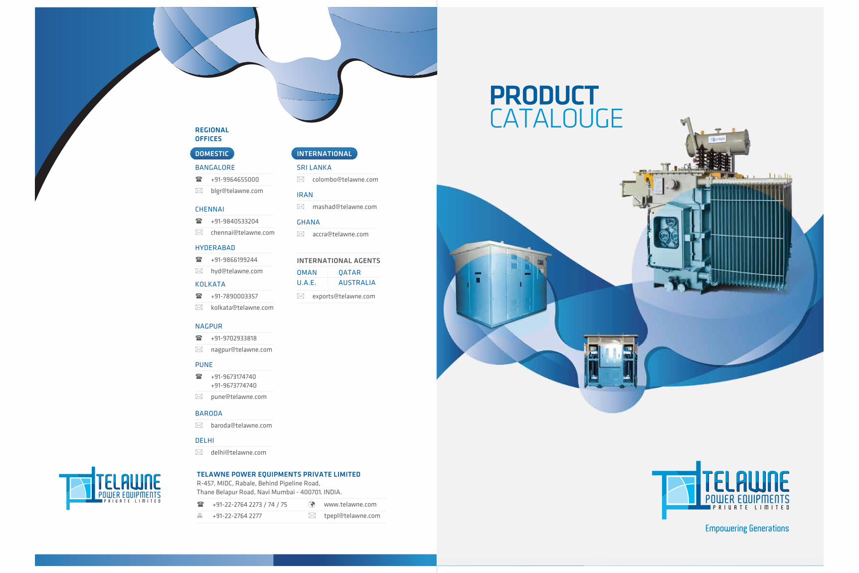
TELAWNE POWER EQUIPMENTS PRIVATE LIMITEDR-457, MIDC, Rabale, Behind Pipeline Road, Thane Belapur Road, Navi Mumbai - 400701. INDIA.
www.telawne.com
+91-22-2764 2273 / 74 / 75
+91-22-2764 2277
CATALOUGEPRODUCT
INTERNATIONAL
Empowering Generations
+91-9840533204
CHENNAI
+91-9866199244
HYDERABAD
+91-7890003357
KOLKATA
+91-9702933818
NAGPUR
REGIONAL OFFICES
DOMESTIC
+91-9964655000
BANGALORE
+91-9673174740 +91-9673774740
PUNE
DELHI
BARODA
SRI LANKA
OMAN QATAR
U.A.E. AUSTRALIA
IRAN
GHANA
INTERNATIONAL AGENTS

Participated in Exhibition in Dubai, Russia, Myanmar.
2015
Telawne Power Equipment is located in Asia’s Largest Manufacturing Zone of Navi Mumbai. The plant is spread over 38000 sq ft. Our founder, Late Shri. Sudhakar Telawne having experience of over 17 years in Crompton Greaves, Mumbai and started producing and servicing oil Immersed distribution transformers, established by name of “Telawne Cromptek” in 1988.
All plants are certified by ISO 9001:2008 and ISO 14001:2004. It has all the necessary Machinery for handling and producing transformers in accordance with IEC:60076
Successfully Type Tested 1250 KVA - 22 kV;5,10 and 20 MVA 33/11 kV Transformers at CPRI, Bangalore.
CPRI
Successfully Type Tested 100 to 2500 KVA - 11 & 22 kV,Oil & Dry Type Transformer, Packaged & Pad Mounted Substations.
ERDA
Complete Type Tested 1000KVA - 11/0.433 kV Oil Cooled Distribution Transformer as per Gulf & African Utility Specification.
ASTA
OVERVIEW
standards. Telawne has a capacity to produce over 750 MVA Transformers per annum in assorted sizes and types.
We are equipped with all infrastructure facilities complete with Epoxy Flooring, Testing Pit (for better safety), Vacuum Oven, Yokogawa Power Analyzer and also the best Human Safety Equipments.
Our success and growth has been mainly due to thrust and emphasis on quality which never compromise to manufacture zero defect transformers.
MILESTONES
Established Indigenous Manufacturing facility at a new location as “Telawne Power Equipments Pvt Ltd.
2003-2004
Expanded infrastructure and testing facility for handling up to 50 MVA 132 kV.
2007-2008
Enhanced additional winding machinery for Foil VPI type Dry Transformer Processing facility.
2010-2011
Installed foil winding machinery. Built separate section for processing Dry type Transformer. Incorporated new casting
plant & partial Discharge (PD) Testing Arrangement
2015-2016
OUR CREDENTIALS
2012 Udyog Bodh 2014 SME
for Business Excellence
for SME Excellence Award 2014
2015 SKOTCH
for Business Excellence
CERTIFICATIONS
2014
VISION MISSION
To be market leader in Energy Efficient Transformers & Unitised Substations and maintain. Consistent growth of more than 50% annually.
To empower as world recognized service provider for Low Loss Transformers & Compact Substations with a zeal to create excellent customer relationshipby being transparent, commited & maintaining Harmonious relationship.
VALUES
Maintain Transparency, Commitments & Harmonious relationship with Employees, Business Associates & Well Wishers. Develop healthy & safe working environment & provide Integrity throughout the Organisation.
MOTTO
EXHIBITIONS
2006
Consistantly Participating in ELECRAMA.
Participated in the Mactech 2010 CICC, Egypt Exhibition also CEEAMA 2010.
2010
Participated in Exhibition on power in Sri Lanka, Ghana.
2014
1 2
New Launch for Pad Mounted and Tower Substation
New Launch for Contenarized Substation
2016
LAUNCH

OIL IMMERSEDDISTRIBUTION TRANSFORMER
Duty, Type
Voltage Class
No of Phases
Frequency
Vector Group
Insulating Fluid
Class of Insulation
Tap Changer
Tapping Range
Winding Material
Applicable Standards
Painting
Outdoor / Indoor, Pole or Ground Mounted
3.3, 6.6, 11, 22, 33 kV or any specific
1 or 3 Phase
50/60 Hz
Dyn1 or Dyn5 or Dyn11 or any specific
PCB FREE Mineral Oil, both inhibited & uninhibited, as per IS/IEC, ASTM D3487 and customer requirement
Class A
Off Circuit or On Load
±2.5% X 2 for OCTC or + 1.25% X 4 & - 1.25% X 8 for OLTC or as per customer requirement
Aluminium or Copper with multi paper covering
IS 2026, IEC 60076, ANSI, IEEE
Enamel, Epoxy, Polyurethane or customer specific
• H. V. Bushing
• L. V. Bushing
• Off Circuit Tap Changer
• Conservator oil filling hole with cap & drain plug
• Under carriage with four bi-directional rollers
• Earthing terminals
• Drain cum bottom filter valve with sampling plug
• Top filter valve with sampling plug
• Plain Oil Level gauge
• Rating diagram plate
• Air release device
• Thermometer Pocket
• Lifting lugs
• Pressed Steel Radiators (Fins or corrugated type)
• Double Diaphragm Explosion Vent
• Silica gel breather
• Additional Neutral bushing
• First filling of oil
*Dimensions and weight & losses may vary for any specific or special requirement.
NO. (kVA) LENGTH (L) BREADTH (B) HEIGHT (H) NO LOAD FULL LOAD (LTRS) (KGS)
1
2
3
4
5
6
7
8
9
10
11
12
13
14
15
16
100
150
200
250
315
400
500
630
750
1000
1250
1600
2000
2500
3000
5000
1200
1250
1300
1400
1500
1600
1700
1800
1900
2200
2300
2400
2600
2800
3200
4500
1400
1500
1500
1600
1700
1800
2000
2100
2150
2200
2600
3000
3200
3300
3400
4200
1500
1600
1700
1750
1800
1850
1900
2000
2200
2350
2400
2600
2400
2800
3000
3200
300
400
480
540
580
720
850
1000
1150
1500
1800
2100
2500
3000
3750
6500
1750
2500
3000
3500
4200
5000
5800
7000
8000
10500
12500
14250
17000
20000
25000
38000
235
350
400
465
490
520
575
650
750
1000
1250
1310
1450
1650
1900
3350
750
1025
1225
1365
1500
1800
2200
2400
2600
4000
4750
5450
6000
7200
8250
12950
SR. RATING OVERALL DIMENSIONS (MM) STANDARD LOSSES (W) OIL QTY. TOTAL WT.
PRODUCT DIAGRAMTECHNICAL SPECIFICATIONS
R
GENERAL DETAILS
GENERAL DETAILSWe at TELAWNE manufacture both hermetically sealed, corrugated radiator type
and conventional rectangular tank type distribution Transformers. These
Transformers are generally used in distribution network for feeding residential,
commercial & bulk consumers. Following are the dimensional, weight & quantity
details along with standard losses for conventional 11 KV distribution transformer
(Off Circuit Type).
OPTIONAL FITTINGS
R R R
• Highest dielectric insulation property to withstand Lightening Impulse.
• Mechanical design to withstand short circuit forces arising during faults.
• Optimum oven heating under vacuum as to achieve desired compression height
and maximum insulation resistance (IR) to windings.
• Adequate ducts between layers, coils, discs for maximum oil flow and reduced
hot spot temperature.
• Step-lap designed CRGO laminations for lower losses and excitation current.
• Pre compressed Insulation material for minimal moisture absorption.
• Detachable Radiators with isolating valves.
• Jacking Pads
• Dial type Oil Temperature Indicator with A/T contacts
• Dial type Winding Temperature Indicator with A/T contacts
• Magnetic Oil Gauge with A/T contacts
• Buchholz relay with A/T contacts
• Marshalling box with control wiring
• Equaliser pipe between conservator & explosion vent
• On Load Tap Changer
• RTCC Panel with automatic voltage Regulator (AVR)
• Pressure Release valve
• DGPT Relay
ASSURED FEATURESR
STANDARD FITTINGS
3 4

5 6
POWERTRANSFORMER
Duty, Type
Voltage Class
No of Phases
Frequency
Vector Group
Insulating Fluid
Class of Insulation
Tap Changer
Tapping Range
Winding Material
Applicable Standards
Painting
Outdoor / Indoor
11, 22, 33, 66 kV or any specific
3 Phase
50/60 Hz
Dyn5 or Dyn11 or YNyn0 any specific
PCB FREE Mineral Oil, both inhibited & uninhibited, as per IS/IEC, ASTM D3487
Class A
Off circuit or on load tap changer
±2.5% X 2 for OCTC or + 1.25% X 4 & - 1.25% X 8 for OLTC or as per customer requirement
Copper with multi paper covering
IS 2026, IEC 60076, ANSI, IEEE
Enamel, Epoxy, Polyurethane or customer specific
• H. V. Bushing / L. V. Bushing
• Conservator oil filling hole
• Bi-directional rollers
• Earthing terminals pads
• Drain cum bottom filter valve
• Top filter valve with sampling plug
• Plain Oil Level gauge
• Rating diagram plate
• Air release device
• Thermometer Pocket
• Lifting lugs
• Pressed steel Radiators (Detachable)
• Double Diaphragm Explosion Vent
• Silica gel breather
• Additional Neutral bushing
• First filling of oil
• Isolating valves for radiator
• Jacking Pads
• Dial type OTI with A/T contacts
• Buchholz relay with A/T contacts
• Marshalling box with control wiring
*Dimensions and weight & Losses may vary for any specific or special requirement.
1
2
3
4
5
6
7
3300
3500
3600
3800
4000
4200
4400
3000
3200
3000
3100
3600
3800
4000
3500
3600
3800
3900
4000
4200
4400
4000
5500
6500
8000
9000
10000
12000
2450
3300
3800
4200
4800
5200
6300
9250
11550
13250
15000
17500
19500
22250
24000
33000
40000
48000
57000
67000
80000
7.15
7.15
7.15
8.35
8.35
8.35
10.00
3500
3700
3800
4000
4200
4400
4600
3000
3200
3000
3100
3600
3800
4000
3300
3400
3600
3700
3800
4000
4200
3000
3900
4500
5000
5400
6000
7000
2700
3600
4200
4600
5200
5700
6800
10850
14150
15000
17850
21500
24500
28250
14000
19000
25000
32000
37000
43000
52000
7.15
7.15
7.15
8.35
8.35
8.35
10.00
1
2
3
4
5
6
7
3150
5000
6300
8000
10000
12500
16000
3150
5000
6300
8000
10000
12500
16000
NO. (kVA) LENGTH (L) BREADTH (B) HEIGHT (H) NO LOAD LOAD % (LTRS) (KGS)
LOW LOSS TRANSFORMER WITH OLTC
STANDARD TRANSFORMER WITH OLTC
SR. RATING OVERALL DIMENSIONS (MM) LOSSES (W) OIL QTY. TOTAL WT
PRODUCT DIAGRAMTECHNICAL SPECIFICATIONS
R
GENERAL DETAILS
GENERAL DETAILSWe manufacture both on load & off circuit tap switch type power transformer.
These Transformers are generally used in receiving substation for feeding residen-
tial, commercial & bulk consumers. Following are the dimension, oil quantity &
weight details along with standard & low losses for 33KV Power transformer with
On Load Tap Changer.
OPTIONAL FITTINGS
R R R
• Highest dielectric insulation property to withstand lightening impulse.
• Mechanical design to withstand short circuit forces arising during faults.
• Optimum oven heating under vacuum as to achieve desired compression height and maximum insulation resistance (IR) to windings.
• Adequate ducts between layers, coils, discs for maximum oil flow and reduced hot spot temperature.
• Step-lap designed CRGO laminations for lower losses and excitation current.
• Pre compressed Insulation material for minimal moisture absorption.
• Permawood rings for uniform clamping.
• Dial type WTI with A/Tcontact
• Magnetic Oil Gauge with A/T contacts
• On Load Tap Changer
• RTCC Panel with automatic voltage Regulator (AVR)
• Pressure Release valve
• DGPT Relay
• Air cell bag
• Scada Compatible OTI & WTI
• Equaliser pipe between conservato & explosion vent
• Annunciators in RTCC panel
• Force cooling arrangement with fan cubical
ASSURED FEATURESR
STANDARD FITTINGS
.

7 8
.
EXTRA HIGH VOLTAGETRANSFORMER
Duty, Type
Voltage Class
No of Phases
Frequency
Vector Group
Insulating Fluid
Class of Insulation
Tap Changer
Tapping Range
Winding Material
Applicable Standards
Painting
Outdoor / Indoor
66, 100, 110, 132, 220 kV or any specific
3 Phase
50/60 Hz
Dyn5 or Dyn11 or YNyn0 any specific
PCB FREE Mineral Oil, both inhibited & uninhibited, as per IS / IEC, ASTM D3487
Class A
Off Circuit or On load tap Changer
±2.5% x 2 for OCTC or +1.25% x 4 & -1.25% x 8 for OLTC or as per customer requirement
Copper with multi paper covering
IS 2026, IEC 60076, ANSI, IEEE
Epoxy, Polyurethane or customer specific
• H.V Bushing / L.V Bushing
• Conservator with oil filling hole
• Rollers (Plain / Flange)
• Earthing terminal pads
• Drain with bottom filter valve
• Top filter valve with sampling plug
• Shut off valve
• Plain oil level gauge
• Rating diagram plate
• Terminal Marking Plate
• Air release device
• Thermometer Pocket
• Lifting lugs
• Pressed Steel Radiators (Detachable)
• Double Diagram Explosion Vent
• Equaliser pipe between
• Silica Gel Breather
• Additional Neutral Bushing
• First filling of oil
• Isolating valves for radiator
• Jacking Pads
• Dial type OTI with A/T contacts
• Dial type WTI with A/T contacts
• Marshalling Box with control wiring
• Buchholz relay with A/T contacts
• Magnetic Oil Gauge with A/T contacts
• Skid under base
• Inspection Cover
• On Load Tap Changer / Off Circuit Tap Changer
• RTCC Panel with automatic voltage regulator (AVR)
*Dimensions and weight & Losses may vary for any specific or special requirement.
1
2
3
4
5
6
7
5100
5800
7000
7500
8000
8400
8600
3900
4500
4900
5000
5100
5650
5750
4100
4400
4750
5200
5750
6000
6150
9
11.5
13
16
20
25
31.5
8300
8400
13000
14000
20000
21000
22000
24000
28000
34000
42000
52000
63000
70000
60
70
85
100
120
150
185
10
10
10
10
10
12.5
12.5
5300
6000
7200
8000
8300
8700
8900
4100
4700
5100
5200
5400
5950
6050
4300
4600
4950
5400
5950
6200
6450
7
9.5
11.5
14
18
21
25
9130
9240
14000
15050
21000
22050
23100
26400
30800
36550
45150
54600
66150
73500
40
48
60
76
92
120
150
10
10
10
10
10
12.5
12.5
1
2
3
4
5
6
7
10/12.5
12.5/16
16/20
20/25
25/31.5
32/40
40/50
10/12.5
12.5/16
16/20
20/25
25/31.5
32/40
40/50
NO. (MVA) LENGTH (L) BREADTH (B) HEIGHT (H) LNO OAD LOAD % (LTRS) (KGS)
LOW LOSS TRANSFORMER WITH OLTC
STANDARD TRANSFORMER WITH OLTC
SR. RATING OVERALL DIMENSIONS (MM) LOSSES (W) OIL QTY. TOTAL WT.
PRODUCT DIAGRAMTECHNICAL SPECIFICATIONS
R
GENERAL DETAILS
GENERAL DETAILSWe manufacture both on load & off circuit tap switch type EHV transformer. EHV
transformer have voltage class 66KV or above. These transformer are generally
used for stepping down voltage from transmission line. EHV transformer generally
have force cooling & on load tap changer. Following are the dimension, oil quantity
& weight details along with standard & low losses for 66kV & 132kV EHV power
transformer with On Load Tap Changer having ONAN /ONAF Cooling.
OPTIONAL FITTINGS
R R R
• Highest Dielectric insulation property to withstand Lightning impulse.
• Step lap designed CRGO laminations for lower losses & excitation current.
• Pre heating of coils under vaccum as to achieve desired compression height & max shrinking of coils.
• Premali wood clamping rings for uniform compression of primary & secondary winding.
• Coil clamping screws for sustaining high mechanical strength due to short circuit forces.
• Adequate ducts between layers, coils, discs for max oil flow & reduced hot spot
temperature.
• Pressure Release Valve
• Air cell bag
• Scada Compatible OTI & WTI
• Annunciator in RTCC panel
• Force cooling arrangement with fan cubical
• Anti vibration pads
• Fire fighting process
• RTD for oil & winding
• Nitrogen purging system
ASSURED FEATURESR
STANDARD FITTINGS

CAST RESIN DRY TYPE TRANSFORMER
Duty, Type
Voltage Class
No of Phases
Frequency
Vector Group
Insulating Fluid
Class of Insulation
Tap Changer
Tapping Range
Winding Material
Applicable Standards
Painting
Outdoor / Indoor Ground Mounted Type
UPTO 33 kV
3 Phase
50/60 Hz
Dyn1 or Dyn5 or Dyn11 or any specific
F or H with Temp Rise of 90 or 115 Deg C or as per customer requirement
Class A
Off Circuit or On Load
+ 2.5% X 2 for OCTC or + 2.5% X 2 & - 2.5% X 6 for OLTC or as per customer requirement
Aluminium or Copper with multi paper covering
IS 11171, IEC 60726
Powder coated with RAL 7032 shade or as per customer requirement
• H.V. Cable box.
• L.V. Cable box with bus bar or bus duct
• Off circuit tap links
• Under carriage with four bi-directional rollers
• Earthing terminals.
• Rating and diagram plate
• Lifting lugs for complete transformer
• Tapping link operation door
• Enclosure with louver panels
• Canopy
• Base channel – 2 Nos.
• Separate neutral bushing on LV side.
• Paint: Powder coated with RAL 7032 Shade
*Dimensions and weight & losses may vary for any specific or special requirement.
PRODUCT DIAGRAMTECHNICAL SPECIFICATIONS
R
GENERAL DETAILS
GENERAL DETAILSAt TELAWNE casting method of these transformers is obtained with the combined
action of vacuum and temperature. The casting method makes it possible to
assure void-free epoxy penetration of both the inner layer and between turn
insulation. These Transformers are specifically needed in distribution network for
feeding basements or stilts of high-rise buildings, hotels, Malls, stadium, air ports,
chemical & refinery plants. Following are the dimensional, weight & quantity
details along with standard losses for conventional 11KV, (off circuit Type) Cast
Resin Transformer (CRT).
OPTIONAL FITTINGS
R R R
• Windings are electrically balanced to minimize axial short circuit forces.
• Coils are held rigidly in place between insulators clamped to the upper and lower
core frames under high compression.
• Precise casting under vacuum enuring low partial discharge.
• Smooth surface finish and robust construction of MV & LV cast Coils.
• Adequate ducts between coils, discs for maximum air flow and reduced hot spot
temperature.
• Step-lap designed CRGO laminations for lower losses and excitation current.
• RTD with A/T contact
• Marshalling box with control wiring
• On Load tap changer with RTCC panel with AVR
• Forced Cooling arrangement
• Neutral Current Transformer
ASSURED FEATURESR
STANDARD FITTINGS
.
1
2
3
4
5
6
7
8
9
10
11
12
13
14
15
1400
1500
1600
1700
1750
1850
1900
2000
2100
2200
2300
2350
2400
2500
2600
1500
1600
1700
1800
1900
2100
2200
2400
2500
2600
2700
2800
3000
3200
3400
1500
1600
1700
1800
1900
2000
2200
2300
2350
2400
2450
2500
2600
2700
2800
400
500
600
700
950
1200
1450
1600
1800
2200
2600
3200
3800
4500
5000
925
1050
1400
1550
1650
2100
2300
2600
3200
3400
3600
4000
4450
5000
6500
1600
2400
3000
3500
4400
4750
5200
6000
7000
9500
11500
13500
16500
20000
23000
100
150
200
250
315
400
500
630
750
1000
1250
1600
2000
2500
3000
NO. (KVA) LENGTH (L) BREADTH (B) HEIGHT (H) NO LOAD LOAD (KGS)
SR. RATING OVERALL DIMENSIONS (MM) LOSSES (W) TOTAL WT.
9 10
SAFETY FEATURES
R Environment Friendly
R Fire Resistance
R Non-Hygroscopic

11 12
VACUUM PRESSURE IMPREGNATEDDRY TYPE TRANSFORMER
Duty, Type
Voltage Class
No of Phases
Frequency
Vector Group
Class of Insulation
Tap Changer Type
Tapping Range
Winding Material
Applicable Standards
Enclosure Painting
Outdoor / Indoor, Pole or Ground Mounted
Upto 22 kV
3 Phase
50/60 Hz
Dyn1 or Dyn5 or Dyn11 or any specific
F or H with Temp Rise of 90 or 115° C or as per customer requirement
Off Circuit or On Load
±2.5% X 2 for OCTC or + 2.5% X 2 & - 2.5% X 6 for OLTC or as per customer requirement
Aluminium or copper with multi paper NOMEXcovering
IS 11171, IEC 60726
Powder coated with RAL 7032 shade or as per customer requirement
• H.V. Cable box
• L.V. Cable box with Bus bar or Bus duct
• Off Circuit Tap links
• Under carriage with four bi-directional Rollers
• Earthing terminals
• Rating and diagram plate
• Lifting lugs for complete Transformer
• Tapping Link operation Door
• Enclosure with Louver Panels
• Canopy
• Base Channel-2 Nos.
• Separate Neutral bushing on LV side
• Paint: Powder Coated with RAL 7032 shade
• Hinged Windows for inspection of core and windings
PRODUCT DIAGRAMTECHNICAL SPECIFICATIONS GENERAL DETAILS
GENERAL DETAILSWe TELAWNE manufacture both hermetically sealed, corrugated radiator type and
conventional open enclosure type vacuum pressure impregnated dry Transformers.
These Transformers are specifically needed in distribution network for feeding
basements or stilts of high-rise buildings, hotels, Malls, stadium, air ports,
chemical & refinery plants. Following are the dimensional & weight details along
with standard losses for conventional 11kV, Dry Type (VPI) Transformer
(off circuit Type).
R R R
• Windings are electrically balanced to minimize axial & radial short circuit forces.
• Coils are held rigidly in place between insulators clamped to the upper and lower core frames under high compression.
• Polyester resin or thixotropic epoxy resin or silicon varnish impregnation as per the application is used.
• High temperature resistant materials are used including Nomex papers, silicone coated fibreglass and pressure sensitive glass tape.
• Adequate ducts between coils, discs for maximum air flow and reduced hot spot temperature.
• Step-lap designed CRGO laminations for lower losses and excitation current.
R OPTIONAL FITTINGS• RTD with A/T contact
• Marshalling box with control wiring
• On Load Tap Changer with RTCC Panel with AVR
• Forced Cooling arrangement
• Neutral Current Transformer
• Space heaters for core & windings
SAFETY FEATURES
R Environment Friendly
R Fire Resistance
R Non-Hygroscopic
ASSURED FEATURESR
STANDARD FITTINGS
*Dimensions and weight & Losses may vary for any specific or special requirement.
NO. (kVA) LENGTH (L) BREADTH (B) HEIGHT (H) NO LOAD FULL LOAD
SR. RATING OVERALL DIMENSIONS (MM) STANDARD LOSSES (W)
1
2
3
4
5
6
7
8
9
10
11
12
13
14
15
100
150
200
250
315
400
500
630
750
1000
1250
1600
2000
2500
3000
1400
1500
1600
1700
1750
1850
1900
2000
2100
2200
2300
2350
2400
2500
2600
1500
1600
1700
1800
1900
2100
2200
2400
2500
2600
2700
2800
3000
3200
3400
1500
1600
1700
1800
1900
2000
2200
2300
2350
2400
2450
2500
2600
2700
2800
400
500
600
700
950
1200
1450
1600
1800
2200
2600
3200
3800
4500
5000
1600
2400
3000
3500
4400
4750
5200
6000
7000
9500
11500
13500
16500
20000
23000
(KGS)
TOTAL WT.
925
1050
1400
1550
1650
2100
2300
2600
3200
3400
3600
4000
4450
5000
6500

13 14
UNITISEDSUBSTATION
• M.S./ CRC Sheet fabricated Enclosure as per IS 14786
• Load Balancing Lifting Hooks
• Collapsible hinge mounted doors
• Perforated sheet & Air ventilation louvers in Transformer section
• Easy removable rain water protection canopy
• For safety doors with alarm & tripping circuit
• Inter connecting MV & LV cables & Bus bars
• Powder coated paint, Shade - RAL 7032 or as per customer request
• Illuminating lamps with MCB
STANDARD FITTINGS
R Completely Factory built
R Superior Aesthetics
R Convenience in portability
R Readyto install & Commission
R Compact in size
R Minimal maintenance
R Suitable for rooftop & Basement
R Tamper proof
SPECIAL FEATURES
PRODUCT DIAGRAM
R
GENERAL DETAILS
GENERAL DETAILSUnitised substation are designed for locations where space and safety is a concern,
population density is high, such as urban centre. Unitised substation is divided in
three section or compartment— Medium Voltage, Transformer and Low Voltage
Switchboard. Unitised substations are designed in accordance with IS 14786 / IEC
61330 standards with degree of protection for IP 23 Transformer and IP 54 for MV &
LV compartments or as per customer requirement.
Following are the dimensional and weight details for a typical 11kV, Unitized
substation with off circuit type oil cooled Transformer.
ASSURED FEATURESR APPLICATIONS
R R RTECHNICAL SPECIFICATIONS Medium Voltage Compartment
Transformer Compartment
Low Voltage Compartment
MV Switchgear
Type of Switchgear
Insulation Medium
Tripping
Short Circuit Rating
Type of cooling
Rating
Voltage
Phase / Frequency
Vector Group
LV Switchgear
Current Rating
Voltage
No. of Poles
Short Circuit Rating
3.3 to 33 kV
LBS / SFU / Circuit Breaker / RMU
SF6 Gas or Vacuum
Fuse / Relay
21 KA or as per customer requirement
Oil Immersed / Dry Type
100 to 2000 kVA
3.3 to 33/0.433 kV or any specific
3 Phase / 50 or 60 Hz.
Dyn1 or Dyn5 or Dyn11 or any specific.
ACB's, MCCB's
Up to 4000 Amps
440 Volts
3 / 4
36 kA or as per customer requirement
1
2
3
4
100 to 250
315 to 630
750 to 1000
1250 to 2000
2600
2800
3000
3200
1800
2000
2200
2400
2000
2200
2400
2600
2500
3800
5200
7000
*Dimensions and weight may vary for any specific or special requirement.
MV RMU/ VCB/ SFU
H.T. Metering/ Loadmanager
Annunciator & Powerpack
Earth fault, overcurrent relay
Scada or P.L.C compatible
M.V. Compartments Transformer Compartment L.V. Compartment
On Load Tap Changer with R.T.C.C. panel & AVR
Pressure Release valve
W.T.I & O.T.I. with Alarm & Trip contacts
Magnetic Oil Gauge with low level contacts
Bucholz Relay with Alarm & Trip contacts
L.T. microprocessor based trip unit
L.T. MFM / Loadmanger
Feeder Pillar (HRC fuse / MCCB Based)
APFCR Panel with capacitor Bank
L.T. Earth fault & Over current relay
IT Industry Airport
Theatre / Mall Construction Site
Refineries Mines
NO. (kVA) LENGTH (L) HEIGHT (H)BREADTH (B) (KGS)
SR. Rating Overall dimensions (mm) Approx WT.

15 16
PAD MOUNTED SUBSTATION
• MS/ CRC Sheet fabricated Enclosure as per IS 14786
• Load Balancing Lifting Hooks
• Collapsible hinge mounted doors
• Corrugated tank for Transformer
• Safety door switches
• Interconnecting MV & LV Bus bars
• Powder coated paint, Shade - RAL 7032 or as per customer requirement
PRODUCT DIAGRAM GENERAL DETAILS
GENERAL DETAILSPad Mounted Substations are designed for use in distribution application as well as
for dedicated loads. Pad mounted substation's are easy to install and are of low
cost. These are basic & simplest configuration required for distribution substation.
Pad Mounted Substation are designed in accordance with IS 14786 / IEC 61330
standards with degree of protection for IP 54 or as per customer requirement.
Following are the dimensional and weight details for a typical 11kV, Pad Mounted
Substation.
R R
SINGLE LINE DIAGRAMR
RTECHNICAL SPECIFICATIONS Medium Voltage Compartment
Transformer Compartment
Low Voltage Compartment
MV Switchgear
Type of Switchgear
Insulation Medium
Tripping
Short Circuit Rating
Installation
Type of cooling
Rating
Voltage
Phase / Frequency
Vector Group
LV Switchgear
Current Rating
Voltage
No. of Poles
Short Circuit Rating
Upto 22 kV
LBS / SFU / Circuit Breaker / RMU / VCB
SF6 Gas or Vacuum
Fuse / Relay
21 kA or as per customer requirement
Outdoor / Indoor Ground Mounted
Oil Immersed / Dry Type
63 to 1000 kVA
6.6 to 22/0.433 kV or any specific
3 Phase / 50 or 60 Hz
Dyn1 or Dyn5 or Dyn11 or any specific
ACB’s, MCCB’s or HRC Fuse
Upto 2000 Amps
440 Volts
3 / 4
36 kA or as per customer requirement
1
2
3
100 to 250
315 to 630
750 to 1000
1600
1800
2000
2000
2200
2400
1800
2000
2200
2000
3200
4000
NO. (kVA) LENGTH (L) HEIGHT (H)BREADTH (B) (KGS)
SR. Rating Overall dimensions (mm) Approx WT.
*Dimensions and weight may vary for any specific or special requirement.
• M.V. Drawout type breaker
• M.V. Earth Fault (E/F), Over Current
(0/C) relay
• Aluminum or copper winding
• Stainless Steel Tank
• DGPT Relay
OPTIONAL FEATURESR
R Completely Factory built
R Superior Aesthetics
R Convenience in portability
R Ready to install & Commission
R Compact in size
R Minimal maintenance
SPECIAL FEATURES
• Pressure Release Valves
• M.V. / L.V. orientation,
made to suit
• L.T. Micro-processor based Trip unit
• L.T. MFM / Load manager
• L.T. Earth Fault (E/F),
Over Current (O/C) relay
Tapping
Specification Oil Type Dry Type
Insulation Class
Temperature Rise
Temperature Protection
Off Circuit Switch
‘A’
Oil / Winding up to 55/65°C
OTI, WTI
Off Circuit Links
‘F’
Winding up to 130°C
RTD
BASIC COMPONENTS

17 18
TOWERSUBSTATION
Tapping
Specification Oil Type Dry Type
Insulation Class
Temperature Rise
Temperature Protection
Off Circuit Switch
‘A’
Oil / Winding up to 55/65°C
OTI, WTI
Off Circuit Links
‘F’
Winding up to 130°C
RTD
PRODUCT DIAGRAMTECHNICAL SPECIFICATIONS Medium Voltage Compartment
Transformer Compartment
Low Voltage Compartment
MV Switchgear
Type of Switchgear
Insulation Medium
Tripping
Short Circuit Rating
Installation
Type of cooling
Voltage
Rating
Phase / Frequency
Vector Group
LV Switchgear
Current Rating
Voltage
No. of Poles
Short Circuit Rating
Upto 22 kV
LBS / SFU / Circuit Breaker / RMU / VCB
SF6 Gas or Vacuum
Fuse / Relay
Upto 20 kA or as per customer requirement
Outdoor / Indoor Ground Mounted
Oil Immersed / Dry Type
63 to 1000 kVA
3.3 to 22/0.433 kV or any specific
3 Phase / 50 or 60 Hz
Dyn1 or Dyn5 or Dyn11 or any specific
ACB’s, MCCB’s or HRC Fuse
Upto 2000 Amps
433 Volts
3 / 4
Upto 50 kA or as per customer requirement
R
GENERAL DETAILS
GENERAL DETAILS
NO. (kVA) LENGTH (L) BREADTH (B) HEIGHT (H) (KGS)
1
2
3
100 to 250
315 to 630
750 to 1000
1800
1800
2000
1800
2000
2000
3800
4000
4400
3000
4000
5250
SR. Rating Overall dimensions (mm) Approx WT.
*Dimensions and weight may vary for any specific or special requirement.
Tower Substations are designed for use in distribution application as well as for dedicated loads. Tower substation’s are easy to install and are of low cost. These are basic & simplest configuration required for distribution substation. Tower Substation are designed in accordance with IS 14786 / IEC 61330 standards with degree of protection for IP 54 with ONAN transformer & with Dry / Cast resin transformer only transformer enclosure with IP 23 or as per customer requirement.
Following are the dimensional and weight details for a typical 11kV, Tower Substation
OPTIONAL FEATURES M.V.Drawout type breaker
M.V. Earth Fault (E/F), Over Current(O/C) relay
Aluminum or copper winding
Stainless Steel Tank
DGPT Relay
Pressure Release Valves
M.V./L.V. Orientation, made to suit
L.T. Micro-Processor Based Trip unit
L.T. MFM/ Load Manager
L.T Earth Fault (E/F), Over Current (O/C) relay
HT metering / Load manager
SCADA or PLC compatible
Feeder pillar (HRC fuse / MCCB based)
Dry type / Cast resin transformer
For ONAN transformer, PRV,MOG, WTI / OTI & Bucholz relay
For Dry / CRT transformer, space heaters, surge arresters, Temp. scannerSINGLE LINE DIAGRAM
R R R
R
R Completely factory built
R Superior Aesthetics
R Convenience in portability
R Ready to install & Commission
R Compact in size
R Minimal maintenance
SPECIAL FEATURES
BASIC COMPONENTS
• MS/ CRC Sheet fabricated Enclosure as per IS 14786
• Load Balancing Lifting Hooks
• Collapsible hinge mounted doors
• MV/LV switchgear enclosure with IP54
• Corrugated tank for ONAN Transformer with IP 54
• Dry & Cast resin transformer enclosure with IP 23
• Safety door switches
• Inter connecting MV & LV cables/ Bus bars
• Powder coated paint, Shade – RAL / IS-5 or as per customer requirement
19 20
CONTAINERISED SOLARSUBSTATION
• M.S./ CRC Sheet fabricated Enclosure as per IS 14786
• Load Balancing Lifting Hooks
• Collapsible hinge mounted doors
• Rain water protection IP 54 for Breaker compartment
• IP 43 for Transformer / Invertors compartments
• For safety doors with alarm & tripping circuit
• Inter connecting MV & LV cables or bus bars from Invertors to Transformer, Transformer to MV Breaker
• Powder coated paint, for HV& LV equipments
• Epoxy / PU paint, Shade - RAL 9003 or as per customer request
• Illuminating lamps with MCB
STANDARD FITTINGS
R Completely Factory built
R Superior Aesthetics
R Convenience in portability
R Ready to install &Commission
R Compact in size
R Minimal maintenance
R Ideally Suitable for on Grid Solar Projects
R Tamper proof
R Numerical Reverse Power Protection Relay
R Numerical 3 pole Differential Relay
SPECIAL FEATURES
PRODUCT DIAGRAM
R
GENERAL DETAILS
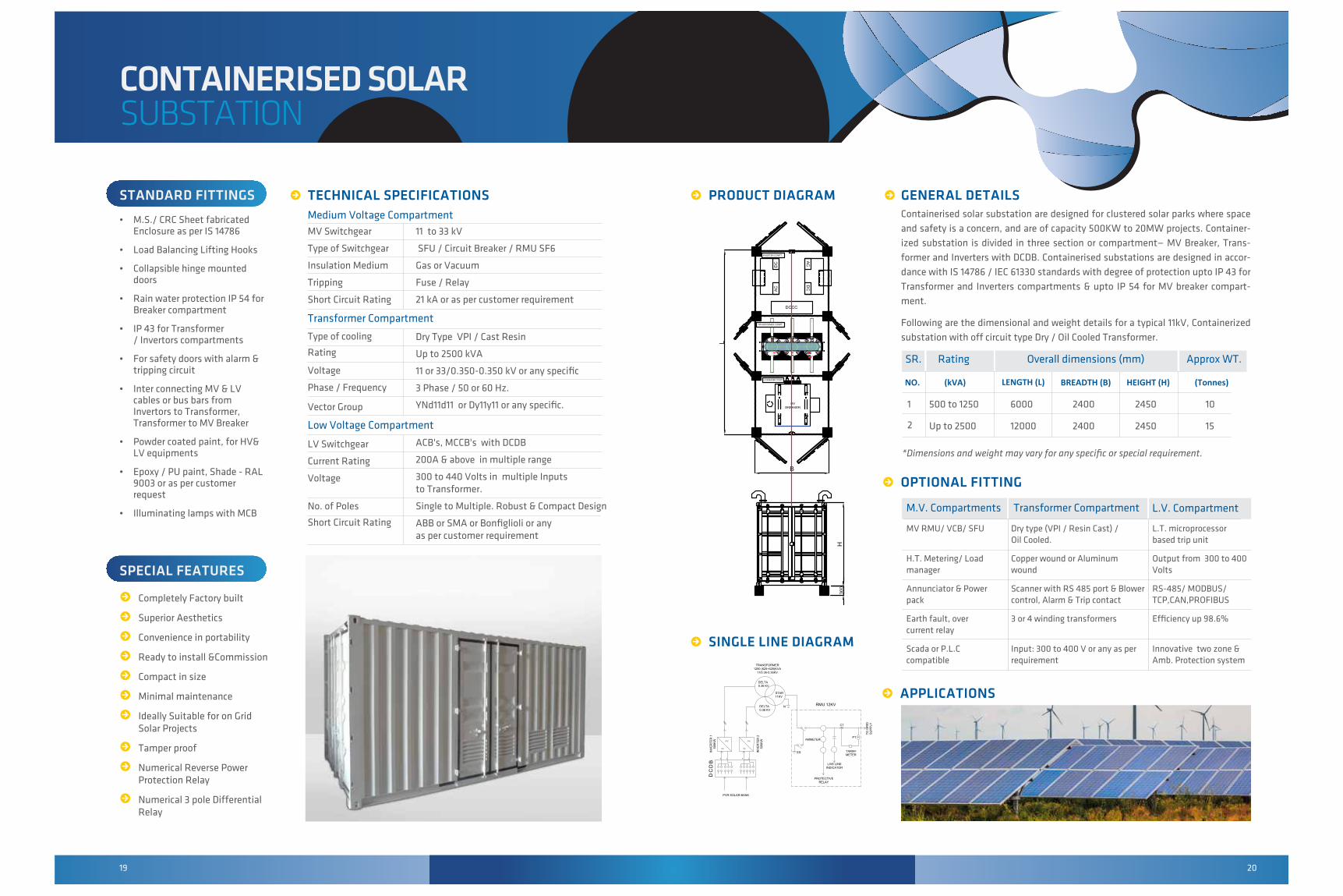
GENERAL DETAILSContainerised solar substation are designed for clustered solar parks where space
and safety is a concern, and are of capacity 500KW to 20MW projects. Container-
ized substation is divided in three section or compartment— MV Breaker, Trans-
former and Inverters with DCDB. Containerised substations are designed in accor-
dance with IS 14786 / IEC 61330 standards with degree of protection upto IP 43 for
Transformer and Inverters compartments & upto IP 54 for MV breaker compart-
ment.
Following are the dimensional and weight details for a typical 11kV, Containerized
substation with off circuit type Dry / Oil Cooled Transformer.
OPTIONAL FITTING
R R RTECHNICAL SPECIFICATIONS Medium Voltage Compartment
Transformer Compartment
Low Voltage Compartment
MV Switchgear
Type of Switchgear
Insulation Medium
Tripping
Short Circuit Rating
Type of cooling
Rating
Voltage
Phase / Frequency
Vector Group
LV Switchgear
Current Rating
Voltage
No. of Poles
Short Circuit Rating
11 to 33 kV
SFU / Circuit Breaker / RMU SF6
Gas or Vacuum
Fuse / Relay
21 kA or as per customer requirement
Dry Type VPI / Cast Resin
Up to 2500 kVA
11 or 33/0.350-0.350 kV or any specific
3 Phase / 50 or 60 Hz.
YNd11d11 or Dy11y11 or any specific.
ACB's, MCCB's with DCDB
200A & above in multiple range
300 to 440 Volts in multiple Inputs to Transformer.
Single to Multiple. Robust & Compact Design
ABB or SMA or Bonfiglioli or anyas per customer requirement
1
2
500 to 1250
Up to 2500
6000
12000
2400
2400
2450
2450
10
15
*Dimensions and weight may vary for any specific or special requirement.
MV RMU/ VCB/ SFU
H.T. Metering/ Loadmanager
Annunciator & Powerpack
Earth fault, overcurrent relay
Scada or P.L.C compatible
M.V. Compartments Transformer Compartment L.V. Compartment
Dry type (VPI / Resin Cast) / Oil Cooled.
Copper wound or Aluminum wound
Scanner with RS 485 port & Blowercontrol, Alarm & Trip contact
3 or 4 winding transformers
Input: 300 to 400 V or any as perrequirement
L.T. microprocessor based trip unit
Output from 300 to 400 Volts
RS-485/ MODBUS/TCP,CAN,PROFIBUS
Efficiency up 98.6%
Innovative two zone &Amb. Protection system
NO. (kVA) LENGTH (L) HEIGHT (H)BREADTH (B) (Tonnes)
SR. Rating Overall dimensions (mm) Approx WT.
SINGLE LINE DIAGRAMR
APPLICATIONSRIN
VE
RTE
R 1
500K
W
TRANSFORMER1250 (625+625)KVA
11/0.36-0.36KV
PVR SOLAR BANK
TO G
RID
SU
PP
LY
DC
DB
DELTA0.36 KV
STAR11KV
DELTA0.36 KV
ES
PROTECTIVERELAY
LIVE LINEINDICATOR
TARIFFMETER
PT
CT
AMMETER
INV
ER
TER
250
0KW
-⁺
N
-⁺
RMU 12KV

21 22
Oman
AfghanistanBangladesh
Philippines
Zambia
Ghana
Togo
Tanzania
Sudan
Saudi Arabia
LiberiaVenezuela
India
Syria
KenyaEthiopiaNigeria
South Africa
Angola
CongoRwanda
3MVA Power Transformer for Arcelor
Mittal Mines, Liberia
150KVA Distribution
Transformers in Higleig,
Sudan
10.5000 KVA, Power X'mer Sagar Sai
Enterprises, Nirmal Nagar, Nagpur
500KVA Dry Type USS, for INOX, Jamnagar,
Gujrat
1500kVA USS Substation for Amponsah Pharmaceuticals, Ghana
GLOBALPRESENCE
Maha Discom / Transco (MSEDCL)/ (MSETCL)
Karnataka Power Co. Ltd. (KPCL)
Southern Railway
Bharat Heavy Electricals Ltd. (BHEL)
National ThermalPower Corp. (NTPC)
National HydroelectricPower Corp. (NHPC)
Ordnance Factories
Oil & Natural GasCorp. (ONGC)
Madhya Pradesh Power Transmission Co. Ltd.
(MPPTCL)
Kerala State Electricity Board Ltd. (KSEB)
Telangana State Electricity Transmission Co. Ltd.
(TSETCL)
Power Utilities I Government Undertakings I Steel I Healthcare I Renewable Energy I Oil and gas I HospitalityReal Estate I Textile I Engineering I Food and Beverage I Automobile I Telecom I Information & Technology.
INDUSTRIES CATERED
Siemens Ltd
IVRCL Infrastructure
Project Ltd
Gammon India Ltd
Rolls Royce Energy Ltd
Jindal Steel Ltd
Larsen & Toubro Ltd
Vadilal Industries Ltd
Tata Power Ltd
Shreem Electric Ltd
ABB LTD.
Harsha Abakus Solar Pvt Ltd.
Gamesa RenewablePvt. Ltd.
CORPORATES& MULTINATIONALS
GOVERNMENT UTILITIES & PUBLIC
SECTOR UNITS
150+EMPLOYEESCOUNTRIES
15+INSTALLATIONS3000+
SQUARE FEET38000+
3600 kVA Distribution Transformer ,Bangladesh.
2500 kVA Distribution Transformer ,Philippines.
6300 kVA Power Trans-former, Afghanistan.


![Report on Ichchhapore substation Substation...2014/07/06 · Date:02/02/2018 Report on Ichchhapore substation Substation: SubstationEquipment: 1] PowerTransformer: A](https://img.dokumen.tips/doc/110x75/6082a7423c38c8542368e070/report-on-ichchhapore-substation-substation-20140706-date02022018-report.jpg)