Embed Size (px)
Citation preview

EDITION 2009
Product catalogue
SAFETY EQUIPMENT

When work is to be carried out on electrical installations, the safety of personnel, materials and system
components must be given the highest priority. Although the safety measures and processes in different
parts of the world are still not standardized, all operators are agreed on one point - safe working can only
be ensured if a number of conditions are met:
Regulations and instructions are followed meticulously and consistently
Personnel have had solid training, and are continuously re-trained
Mutual reliance when carrying out work on electrical installations
Use of reliable tools and work equipment
In no Other Field of Application is the Quality of Tools and Work Equipment so Important.
It is here that, for decades, PFISTERER products have constantly been setting new standards. Our product
range includes solutions that are tailored exactly to each specific requirement, and based on five safety rules recognised around the world:
Isolate
Reclosing lockout to prevent restarting
Verify absence of voltage
Earthing and short-circuiting measures
Cover or safeguard any adjacent live parts
The Standard in Matters of Safety. PFISTERER.

Backed up by decades of experience in developing safety equipment, and with our practical know-how, we know
exactly how operators think and work. So no one knows all the requirements better than we do. Our highly-qua-
lified staff applies this know-how in their development work, in the laboratory and in production. And the result is: uniquely reliable safety equipment.
Our core competence is in securing the absence of voltage and the earthing and short-circuiting of system com-
ponents. Our product range includes:
Capacitive voltage detectors for power systems above 1 kV AC.
Double-pole voltage detectors for power systems between 500 V and 4,000 V DC
Voltage detector types adapted to almost all existing railway systems
Phase comparators and voltage-difference detecting devices for three-phase applications
Voltage detecting systems for gas-insulated load switching equipment and switchgear
Earthing and short-circuiting devices in all useful types and variations for high short-circuit loads
Earth clamps, line clamps and connection elements for all common applications
Insulating poles as earthing or operating poles
Every PFISTERER safety product is matched exactly to the corresponding customer requirement. Special IT-
assisted logistics processes have been developed for the earthing and short-circuiting devices. This means short
delivery times, even for special variants.
This product catalogue shows a representative selection of the most popular items in our product range.
We can supply additional types and add-ons on request.

4 www.pfisterer.com
Contents
5www.pfisterer.com
IIIOperating Poles Page | 36 - 41
Phase Comparators Page | 32 - 35
Voltage Detectors Page | 10 - 31
II
I
Contents
VEarthing and Short-circuiting Devices Page | 48 - 81
Earthing Poles Page | 42 - 47 IV
VlVoltage Detecting Systems Page | 82 - 88
VllAccessories Page | 89 - 99

� www.pfisterer.com
Spannungsprüfer
Earthing Poles
Phase Comparators
Operating Poles
Voltage Detectors
Contents
�www.pfisterer.com
I
IV
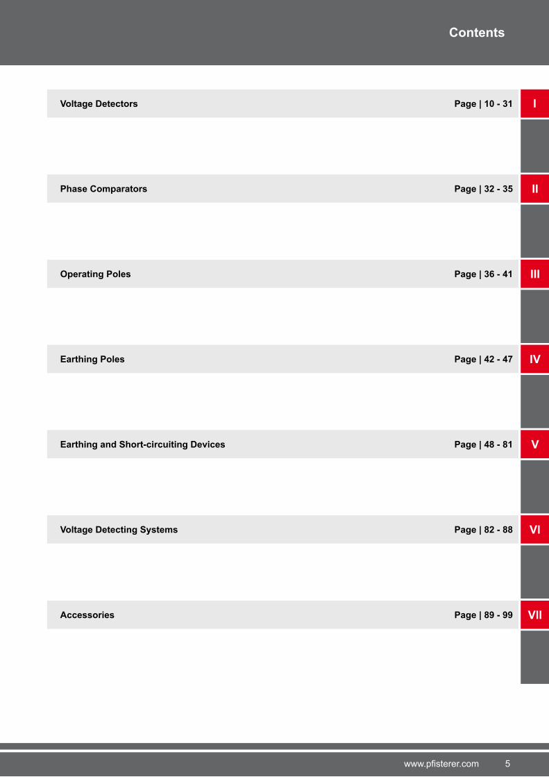
Earthing Poles
Page 42 – 45
Earthing Poles for
Railway Systems
Page 4� – 4�
Page | 42 – 47
IIPage | 32 – 35
Page | 36 – 41
Insulating Poles
Page 3� – 3�
Switching Poles
Page 38
Insulating Working Poles
Page 39 – 40
III
Voltage Detectors for
Medium Voltage
Page 11 – 14
Voltage Detectors for
High Voltage
Page 15 – 1�
Insulating Poles for
Voltage Detectors
Page 25 – 30
Voltage Detectors for
Railway Systems
Page 1� – 24
Single-pole Phase
Comparators
Page 32 – 33Deltameter 5
Page 34
Fuse Tongs
Page 41
In-service tests for
voltage detectors
Page 31
In-service Tests for
Phase Comparators
Page 35
Page | 10 – 31
Contents

8 www.pfisterer.com
Spannungsprüfer
Voltage Detecting Systems
Accessories
Earthing and Short-circuiting Devices
Contents
9www.pfisterer.com
V
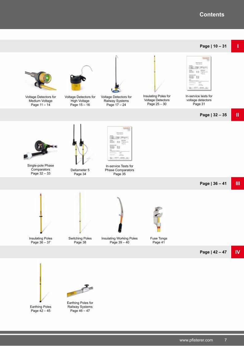
Indicators
Page 82 – 84
VIPage | 82 – 88
Page | 89 – 99
Accessories
Page 89 – 9�
VII
Earthing and
Short-circuiting Devices
Page 48 – 5�
Special
Earthing Fittings
Page 58
Earth Clamps
Page �2 – �9
Earthing and Short-circuiting
Devices for Railway Systems
Page 59 – �1
Contact Wire
Earth Clamps
Page �5 – ��
Line Clamps
Page �1 – �4
Interfaces and
Connecting Leads
Page 85
In-service Tests for
EPV Phase Comparators
Page 88
Testers
Page 8� – 88
Rail Earth Clamps
Page �0
Earthing and
Phase Fixed Points
Page �� – 81
Page | 48 – 81
Spare Parts
Page 98 – 99
Contents
10 www.pfisterer.com
I
Vo
ltag
e D
ete
cto
rs
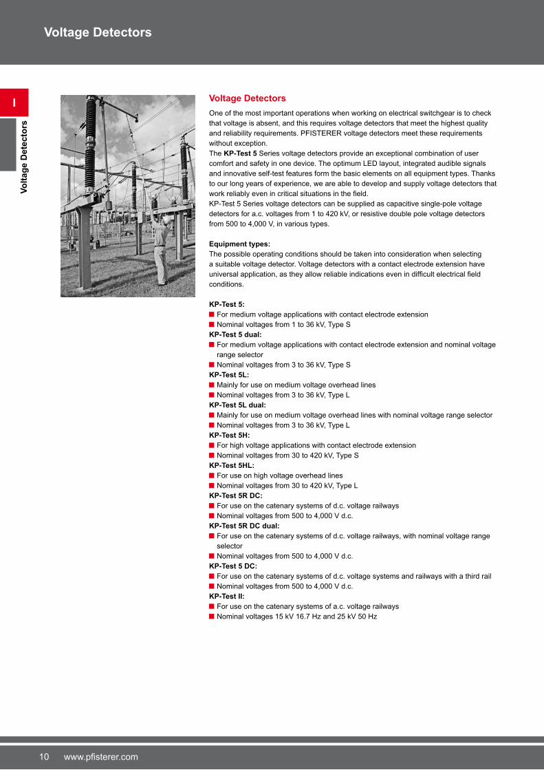
Voltage Detectors
Voltage Detectors
One of the most important operations when working on electrical switchgear is to check
that voltage is absent, and this requires voltage detectors that meet the highest quality
and reliability requirements. PFISTERER voltage detectors meet these requirements
without exception.
The KP-Test 5 Series voltage detectors provide an exceptional combination of user
comfort and safety in one device. The optimum LED layout, integrated audible signals
and innovative self-test features form the basic elements on all equipment types. Thanks
to our long years of experience, we are able to develop and supply voltage detectors that
work reliably even in critical situations in the field.KP-Test 5 Series voltage detectors can be supplied as capacitive single-pole voltage
detectors for a.c. voltages from 1 to 420 kV, or resistive double pole voltage detectors
from 500 to 4,000 V, in various types.
Equipment types:
The possible operating conditions should be taken into consideration when selecting
a suitable voltage detector. Voltage detectors with a contact electrode extension have
universal application, as they allow reliable indications even in difficult electrical field conditions.
KP-Test 5:
For medium voltage applications with contact electrode extension
Nominal voltages from 1 to 3� kV, Type S
KP-Test 5 dual:
For medium voltage applications with contact electrode extension and nominal voltage
range selector
Nominal voltages from 3 to 3� kV, Type S
KP-Test 5L:
Mainly for use on medium voltage overhead lines
Nominal voltages from 3 to 3� kV, Type L
KP-Test 5L dual:
Mainly for use on medium voltage overhead lines with nominal voltage range selector
Nominal voltages from 3 to 3� kV, Type L
KP-Test 5H:
For high voltage applications with contact electrode extension
Nominal voltages from 30 to 420 kV, Type S
KP-Test 5HL:
For use on high voltage overhead lines
Nominal voltages from 30 to 420 kV, Type L
KP-Test 5R DC:
For use on the catenary systems of d.c. voltage railways
Nominal voltages from 500 to 4,000 V d.c.
KP-Test 5R DC dual:
For use on the catenary systems of d.c. voltage railways, with nominal voltage range
selector
Nominal voltages from 500 to 4,000 V d.c.
KP-Test 5 DC:
For use on the catenary systems of d.c. voltage systems and railways with a third rail
Nominal voltages from 500 to 4,000 V d.c.
KP-Test II:
For use on the catenary systems of a.c. voltage railways
Nominal voltages 15 kV 1�.� Hz and 25 kV 50 Hz
11www.pfisterer.com
Voltage Detectors
I
Vo
ltag
e D
ete
cto
rs
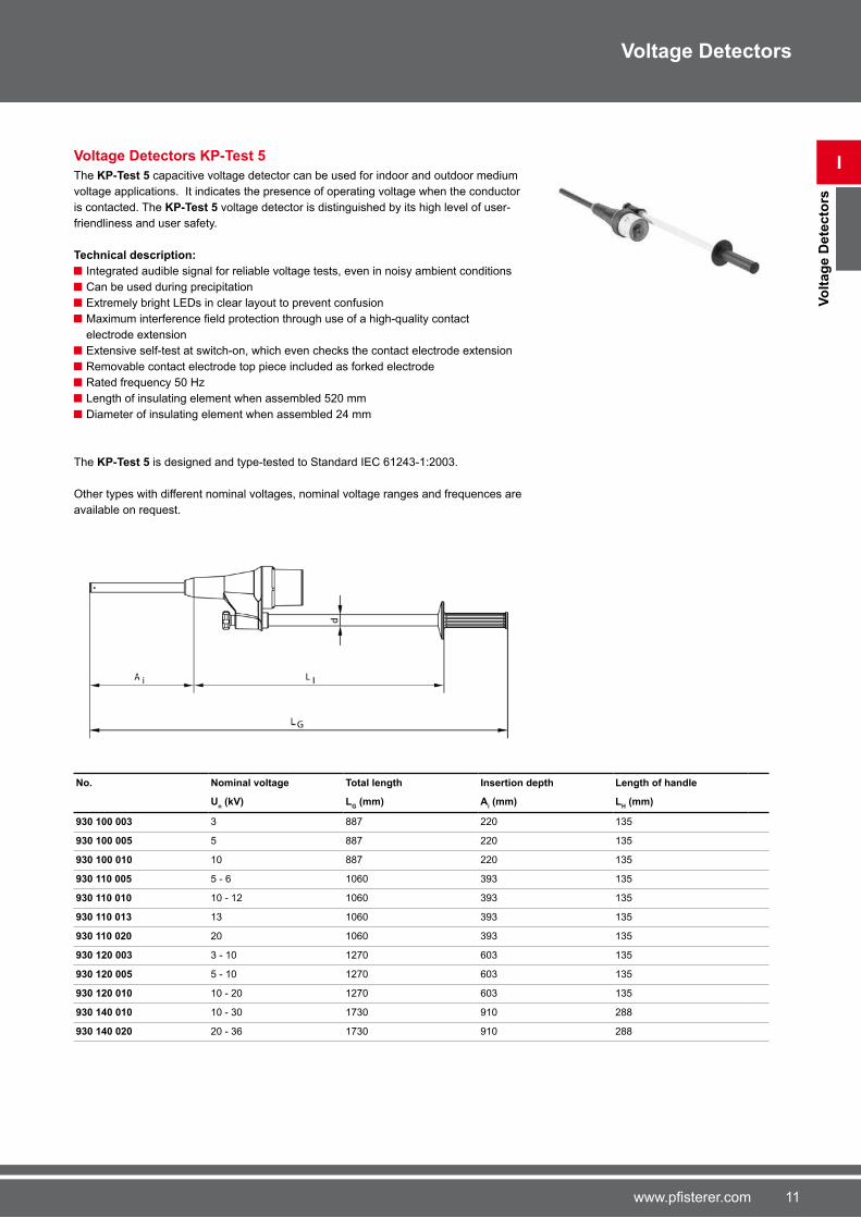
Voltage Detectors KP-Test 5
The KP-Test 5 capacitive voltage detector can be used for indoor and outdoor medium
voltage applications. It indicates the presence of operating voltage when the conductor
is contacted. The KP-Test 5 voltage detector is distinguished by its high level of user-
friendliness and user safety.
Technical description:
Integrated audible signal for reliable voltage tests, even in noisy ambient conditions
Can be used during precipitation
Extremely bright LEDs in clear layout to prevent confusion
Maximum interference field protection through use of a high-quality contact electrode extension
Extensive self-test at switch-on, which even checks the contact electrode extension
Removable contact electrode top piece included as forked electrode
Rated frequency 50 Hz
Length of insulating element when assembled 520 mm
Diameter of insulating element when assembled 24 mm
The KP-Test 5 is designed and type-tested to Standard IEC �1243-1:2003.
Other types with different nominal voltages, nominal voltage ranges and frequences are
available on request.
No. Nominal voltage Total length Insertion depth Length of handle
Un (kV) L
G (mm) A
i (mm) L
H (mm)
930 100 003 3 88� 220 135
930 100 005 5 88� 220 135
930 100 010 10 88� 220 135
930 110 005 5 - � 10�0 393 135
930 110 010 10 - 12 10�0 393 135
930 110 013 13 10�0 393 135
930 110 020 20 10�0 393 135
930 120 003 3 - 10 12�0 �03 135
930 120 005 5 - 10 12�0 �03 135
930 120 010 10 - 20 12�0 �03 135
930 140 010 10 - 30 1�30 910 288
930 140 020 20 - 3� 1�30 910 288
12 www.pfisterer.com
I
Vo
ltag
e D
ete
cto
rs f
or
Med
ium
Vo
ltag
e
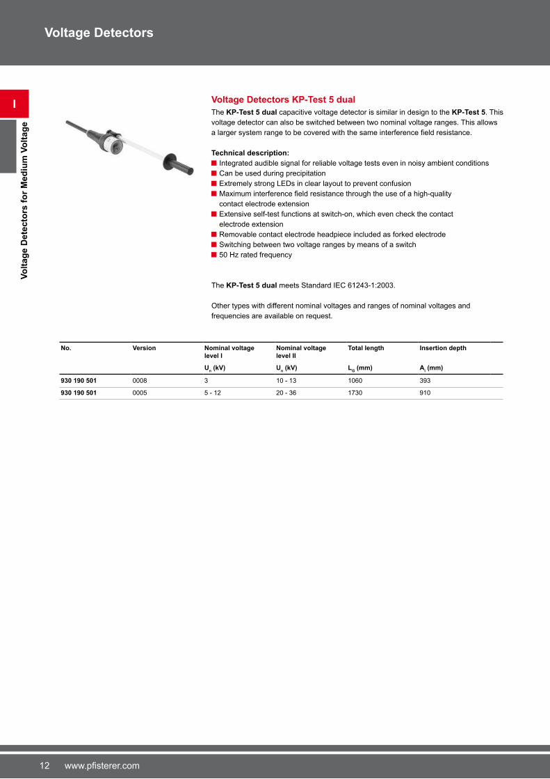
Voltage Detectors KP-Test 5 dual
The KP-Test 5 dual capacitive voltage detector is similar in design to the KP-Test 5. This
voltage detector can also be switched between two nominal voltage ranges. This allows
a larger system range to be covered with the same interference field resistance.
Technical description:
Integrated audible signal for reliable voltage tests even in noisy ambient conditions
Can be used during precipitation
Extremely strong LEDs in clear layout to prevent confusion
Maximum interference field resistance through the use of a high-quality contact electrode extension
Extensive self-test functions at switch-on, which even check the contact
electrode extension
Removable contact electrode headpiece included as forked electrode
Switching between two voltage ranges by means of a switch
50 Hz rated frequency
The KP-Test 5 dual meets Standard IEC �1243-1:2003.
Other types with different nominal voltages and ranges of nominal voltages and
frequencies are available on request.
No. Version Nominal voltage level I
Nominal voltage level II
Total length Insertion depth
Un (kV) U
n (kV) L
G (mm) A
i (mm)
930 190 501 0008 3 10 - 13 10�0 393
930 190 501 0005 5 - 12 20 - 3� 1�30 910
Voltage Detectors
13www.pfisterer.com
I
Vo
ltag
e D
ete
cto
rs f
or
Med
ium
Vo
ltag
e
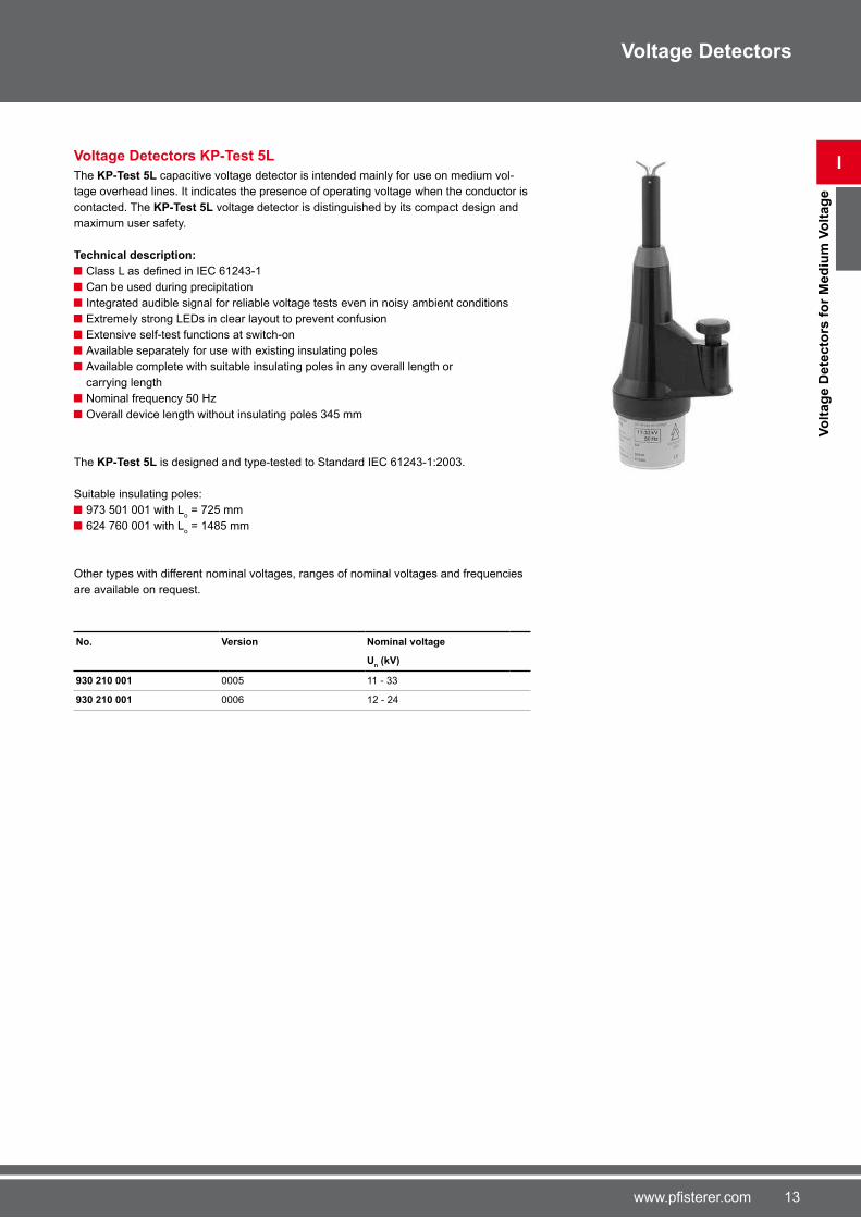
Voltage Detectors KP-Test 5L
The KP-Test 5L capacitive voltage detector is intended mainly for use on medium vol-
tage overhead lines. It indicates the presence of operating voltage when the conductor is
contacted. The KP-Test 5L voltage detector is distinguished by its compact design and
maximum user safety.
Technical description:
Class L as defined in IEC 61243-1 Can be used during precipitation
Integrated audible signal for reliable voltage tests even in noisy ambient conditions
Extremely strong LEDs in clear layout to prevent confusion
Extensive self-test functions at switch-on
Available separately for use with existing insulating poles
Available complete with suitable insulating poles in any overall length or
carrying length
Nominal frequency 50 Hz
Overall device length without insulating poles 345 mm
The KP-Test 5L is designed and type-tested to Standard IEC �1243-1:2003.
Suitable insulating poles:
9�3 501 001 with Lo = �25 mm
�24 ��0 001 with Lo = 1485 mm
Other types with different nominal voltages, ranges of nominal voltages and frequencies
are available on request.
No. Version Nominal voltage
Un (kV)
930 210 001 0005 11 - 33
930 210 001 000� 12 - 24
Voltage Detectors

14 www.pfisterer.com
I
Vo
ltag
e D
ete
cto
rs f
or
Med
ium
Vo
ltag
e
Voltage Detectors
Voltage Detectors KP-Test 5L dual
The KP-Test 5L dual capacitive voltage detector is similar in design to the KP-Test 5L.
This voltage detector can also be switched between two nominal voltage ranges.
This allows a larger system range to be covered with the same interference field re-
sistance.
Technical description:
Class L as defined in IEC 61243-1 Can be used during precipitation
Switching between two voltage ranges using a switch
Integrated audible signal for reliable voltage tests even in noisy ambient conditions
Extremely strong LEDs in clear layout to prevent confusion
Extensive self-test functions at switch-on
Available separately for use with existing insulating poles
Available complete with suitable insulating poles in any overall length or
carrying length
Nominal frequency 50 Hz
Overall device length without insulating poles 345 mm
The KP-Test 5L dual meets Standard IEC �1243-1:2003.
Suitable insulating poles:
9�3 501 001 with Lo = �25 mm
�24 ��0 001 with Lo = 1485 mm
Other types with different nominal voltages, ranges of nominal voltages and frequencies
are available on request.
No. Version Nominal voltage level I
Nominal voltage level II
Un (kV) U
n (kV)
930 210 501 0005 3 - 10 11 - 3�
15www.pfisterer.com
I
Vo
ltag
e D
ete
cto
rs f
or
Hig
h V
olt
ag
e
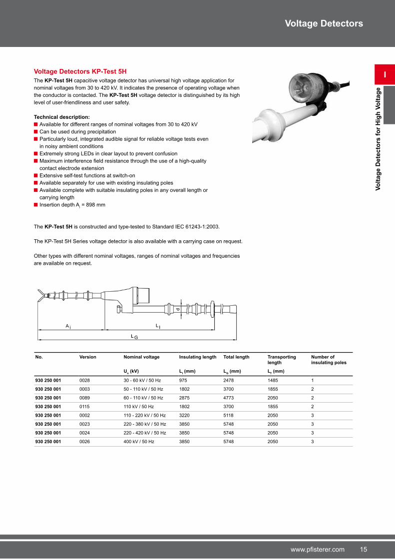
Voltage Detectors KP-Test 5H
The KP-Test 5H capacitive voltage detector has universal high voltage application for
nominal voltages from 30 to 420 kV. It indicates the presence of operating voltage when
the conductor is contacted. The KP-Test 5H voltage detector is distinguished by its high
level of user-friendliness and user safety.
Technical description:
Available for different ranges of nominal voltages from 30 to 420 kV
Can be used during precipitation
Particularly loud, integrated audible signal for reliable voltage tests even
in noisy ambient conditions
Extremely strong LEDs in clear layout to prevent confusion
Maximum interference field resistance through the use of a high-quality contact electrode extension
Extensive self-test functions at switch-on
Available separately for use with existing insulating poles
Available complete with suitable insulating poles in any overall length or
carrying length
Insertion depth Ai = 898 mm
The KP-Test 5H is constructed and type-tested to Standard IEC �1243-1:2003.
The KP-Test 5H Series voltage detector is also available with a carrying case on request.
Other types with different nominal voltages, ranges of nominal voltages and frequencies
are available on request.
No. Version Nominal voltage Insulating length Total length Transporting length
Number of insulating poles
Un (kV) L
I (mm) L
G (mm) L
T (mm)
930 250 001 0028 30 - �0 kV / 50 Hz 9�5 24�8 1485 1
930 250 001 0003 50 - 110 kV / 50 Hz 1802 3�00 1855 2
930 250 001 0089 �0 - 110 kV / 50 Hz 28�5 4��3 2050 2
930 250 001 0115 110 kV / 50 Hz 1802 3�00 1855 2
930 250 001 0002 110 - 220 kV / 50 Hz 3220 5118 2050 3
930 250 001 0023 220 - 380 kV / 50 Hz 3850 5�48 2050 3
930 250 001 0024 220 - 420 kV / 50 Hz 3850 5�48 2050 3
930 250 001 002� 400 kV / 50 Hz 3850 5�48 2050 3
Voltage Detectors
1� www.pfisterer.com
I
Vo
ltag
e D
ete
cto
rs f
or
Hig
h V
olt
ag
e
Voltage Detectors
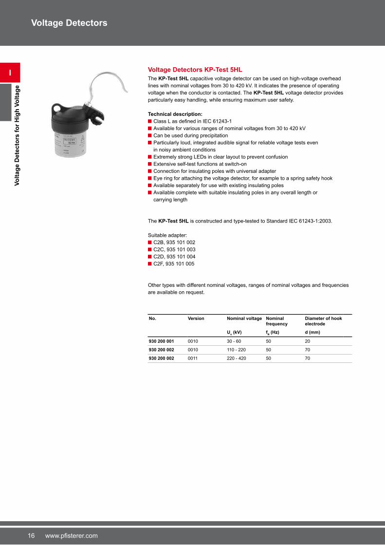
Voltage Detectors KP-Test 5HL
The KP-Test 5HL capacitive voltage detector can be used on high-voltage overhead
lines with nominal voltages from 30 to 420 kV. It indicates the presence of operating
voltage when the conductor is contacted. The KP-Test 5HL voltage detector provides
particularly easy handling, while ensuring maximum user safety.
Technical description:
Class L as defined in IEC 61243-1 Available for various ranges of nominal voltages from 30 to 420 kV
Can be used during precipitation
Particularly loud, integrated audible signal for reliable voltage tests even
in noisy ambient conditions
Extremely strong LEDs in clear layout to prevent confusion
Extensive self-test functions at switch-on
Connection for insulating poles with universal adapter
Eye ring for attaching the voltage detector, for example to a spring safety hook
Available separately for use with existing insulating poles
Available complete with suitable insulating poles in any overall length or
carrying length
The KP-Test 5HL is constructed and type-tested to Standard IEC �1243-1:2003.
Suitable adapter:
C2B, 935 101 002
C2C, 935 101 003
C2D, 935 101 004
C2F, 935 101 005
Other types with different nominal voltages, ranges of nominal voltages and frequencies
are available on request.
No. Version Nominal voltage Nominal frequency
Diameter of hook electrode
Un (kV) f
N (Hz) d (mm)
930 200 001 0010 30 - �0 50 20
930 200 002 0010 110 - 220 50 �0
930 200 002 0011 220 - 420 50 �0
1�www.pfisterer.com
I
Vo
ltag
e D
ete
cto
rs f
or
Railw
ay S
yste
ms
Voltage Detectors
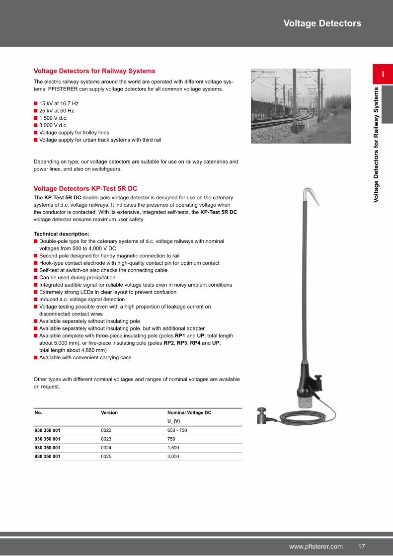
Voltage Detectors for Railway Systems
The electric railway systems around the world are operated with different voltage sys-
tems. PFISTERER can supply voltage detectors for all common voltage systems.
15 kV at 1�.� Hz
25 kV at 50 Hz
1,500 V d.c.
3,000 V d.c.
Voltage supply for trolley lines
Voltage supply for urban track systems with third rail
Depending on type, our voltage detectors are suitable for use on railway catenaries and
power lines, and also on switchgears.
Voltage Detectors KP-Test 5R DC
The KP-Test 5R DC double-pole voltage detector is designed for use on the catenary
systems of d.c. voltage railways. It indicates the presence of operating voltage when
the conductor is contacted. With its extensive, integrated self-tests, the KP-Test 5R DC
voltage detector ensures maximum user safety.
Technical description:
Double-pole type for the catenary systems of d.c. voltage railways with nominal
voltages from 500 to 4,000 V DC
Second pole designed for handy magnetic connection to rail
Hook-type contact electrode with high-quality contact pin for optimum contact
Self-test at switch-on also checks the connecting cable
Can be used during precipitation
Integrated audible signal for reliable voltage tests even in noisy ambient conditions
Extremely strong LEDs in clear layout to prevent confusion
Induced a.c. voltage signal detection
Voltage testing possible even with a high proportion of leakage current on
disconnected contact wires
Available separately without insulating pole
Available separately without insulating pole, but with additional adapter
Available complete with three-piece insulating pole (poles RP1 and UP; total length
about 5,000 mm), or five-piece insulating pole (poles RP2, RP3, RP4 and UP;
total length about 4,880 mm)
Available with convenient carrying case
Other types with different nominal voltages and ranges of nominal voltages are available
on request.
No. Version Nominal Voltage DC
Un (V)
930 350 001 0022 �50 - �50
930 350 001 0023 �50
930 350 001 0024 1,500
930 350 001 0025 3,000

18 www.pfisterer.com
I
Vo
ltag
e D
ete
cto
rs f
or
Railw
ay S
yste
ms
Voltage Detectors
Voltage Detectors KP-Test 5R DC dual
The KP-Test 5R DC dual double-pole voltage detector is similar in design to the
KP-Test 5R DC. This voltage detector can also be switched between two nominal
voltage ranges in two steps. This allows a larger system range to be covered even
when there is a high proportion of leakage current.
The KP-Test 5R DC dual has two selectable voltage steps.
Step 1:
Voltage �50 V DC
Selected by briefly pressing the On button LED indicator: 1 x green
Step 2:
Voltage 1,500 V DC
Selected by pressing and holding the On button
LED indicator: 2 x green
Sensible voltage level selection at switch-on and the related self-test ensure that the
KP-Test 5R DC dual displays safe, clear indications.
Technical description:
Double-pole type for the catenary systems of d.c. voltage railways with nominal
voltages from 500 to 4,000 V DC
Second pole designed for handy magnetic connection to rail
Voltage range selection
Hook-type contact electrode with high-quality contact pin for optimum contact
Self-test at switch-on also checks the connecting cable
Can be used during precipitation
Integrated audible signal for reliable voltage tests even in noisy ambient conditions
Extremely strong LEDs in clear layout to prevent confusion
Induced a.c. voltage signal detection
Voltage testing possible even with a high proportion of leakage current on
disconnected contact wires
Available separately without insulating pole
Available separately without insulating pole, but with additional adapter
Available complete with three-piece insulating pole (poles RP1 and UP; total length
about 5,000 mm), or five-piece insulating pole (poles RP2, RP3, RP4 and UP;
total length about 4,880 mm)
Available with convenient carrying case
Other types with different nominal voltages and ranges of nominal voltages are available
on request.
No. Version Nominal voltage DC Level I
Nominal voltage DC Level II
Un (V) U
n (V)
930 350 501 0005 �50 1,500
19www.pfisterer.com
I
Vo
ltag
e D
ete
cto
rs f
or
Railw
ay S
yste
ms
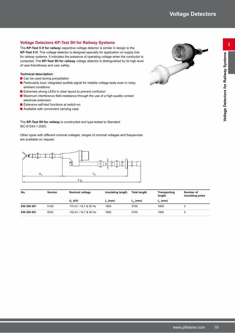
Voltage Detectors KP-Test 5H for Railway Systems
The KP-Test 5 H for railway capacitive voltage detector is similar in design to the
KP-Test 5 H. This voltage detector is designed specially for application on supply line
for railway systems. It indicates the presence of operating voltage when the conductor is
contacted. The KP-Test 5H for railway voltage detector is distinguished by its high level
of user-friendliness and user safety.
Technical description:
Can be used during precipitation
Particularly loud, integrated audible signal for reliable voltage tests even in noisy
ambient conditions
Extremely strong LEDs in clear layout to prevent confusion
Maximum interference field resistance through the use of a high-quality contact electrode extension
Extensive self-test functions at switch-on
Available with convenient carrying case
The KP-Test 5H for railway is constructed and type-tested to Standard
IEC �1243-1:2003.
Other types with different nominal voltages, ranges of nominal voltages and frequencies
are available on request.
No. Version Nominal voltage Insulating length Total length Transporting length
Number of insulating poles
Un (kV) L
I (mm) L
G (mm) L
T (mm)
930 250 001 0128 110 kV / 1�,� & 50 Hz 1802 3�00 1855 2
930 250 001 0032 132 kV / 1�,� & 50 Hz 1802 3�00 1855 2
Voltage Detectors

20 www.pfisterer.com
I
Vo
ltag
e D
ete
cto
rs f
or
Railw
ay S
yste
ms
Voltage Detectors
Voltage Detectors KP-Test 5 for Railway Power Lines
The KP-Test 5 capacitive voltage detector for railway power lines can be used on
15 kV 1�.� Hz railway power lines. It indicates the presence of operating voltage when
the conductor is contacted. This voltage detector is suitable for the particular require-
ments of railway power lines.
Technical description:
Integrated audible signal for reliable voltage tests even in noisy ambient conditions
Can be used during precipitation
Extremely strong LEDs in clear layout to prevent confusion
Maximum interference field resistance through the use of a high-quality contact electrode extension
Extensive self-test functions at switch-on, which even check the contact electrode
extension
Removable contact electrode headpiece as hook electrode
Handle length 288 mm
Length of insulating element 520 mm
No. Version Nominal voltage
Nominal frequency
Total length Insertion depth
Un (kV) f
N (Hz) L
G (mm) A
i (mm)
930 190 001 0025 15 1�.� 1810 910

21www.pfisterer.com
I
Vo
ltag
e D
ete
cto
rs f
or
Railw
ay S
yste
ms
Voltage Detectors
Voltage Detectors KP-Test 5 for Railway Substation
The KP-Test 5 capacitive voltage detector for railway substation can be used on
15 kV 1�.� Hz.It indicates the presence of operating voltage when the conductor is
contacted. The KP-Test 5 capacitive voltage detector for railway substation voltage
detector is distinguished by its high level of user-friendliness and user safety.
Technical description:
Can be used during precipitation
Particularly loud, integrated audible signal for reliable voltage tests even in
noisy ambient conditions
Extremely strong LEDs in clear layout to prevent confusion
Maximum interference field resistance through the use of a high-quality contact electrode extension
Extensive self-test functions at switch-on, which even check the contact electrode
extension
No. Version Total length Insertion depth Length of insulating element
Length of handle
LG (mm) A
i (mm) L
I (mm) L
H (mm)
930 190 001 0122 12�0 �03 520 135
22 www.pfisterer.com
I
Vo
ltag
e D
ete
cto
rs f
or
Railw
ay S
yste
ms
Voltage Detectors
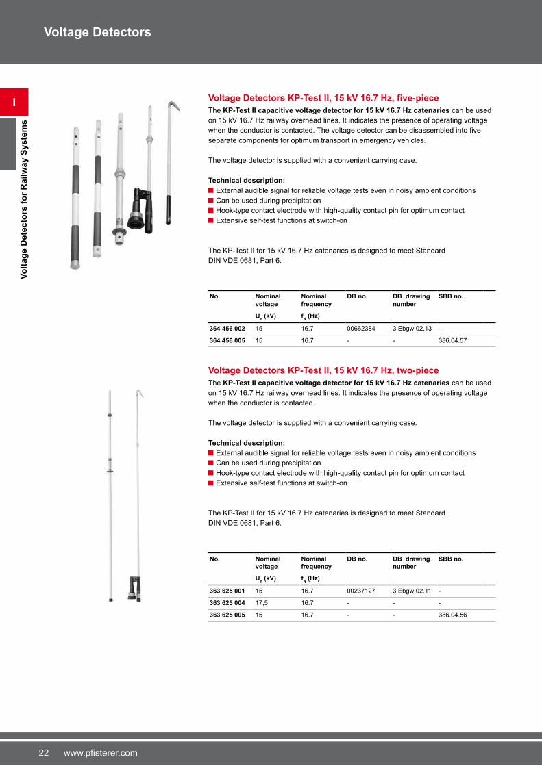
Voltage Detectors KP-Test II, 15 kV 16.7 Hz, five-piece
The KP-Test II capacitive voltage detector for 15 kV 16.7 Hz catenaries can be used
on 15 kV 1�.� Hz railway overhead lines. It indicates the presence of operating voltage
when the conductor is contacted. The voltage detector can be disassembled into five separate components for optimum transport in emergency vehicles.
The voltage detector is supplied with a convenient carrying case.
Technical description:
External audible signal for reliable voltage tests even in noisy ambient conditions
Can be used during precipitation
Hook-type contact electrode with high-quality contact pin for optimum contact
Extensive self-test functions at switch-on
The KP-Test II for 15 kV 1�.� Hz catenaries is designed to meet Standard
DIN VDE 0�81, Part �.
No. Nominal voltage
Nominal frequency
DB no. DB drawing number
SBB no.
Un (kV) f
N (Hz)
364 456 002 15 1�.� 00��2384 3 Ebgw 02.13 -
364 456 005 15 1�.� - - 38�.04.5�
Voltage Detectors KP-Test II, 15 kV 16.7 Hz, two-piece
The KP-Test II capacitive voltage detector for 15 kV 16.7 Hz catenaries can be used
on 15 kV 1�.� Hz railway overhead lines. It indicates the presence of operating voltage
when the conductor is contacted.
The voltage detector is supplied with a convenient carrying case.
Technical description:
External audible signal for reliable voltage tests even in noisy ambient conditions
Can be used during precipitation
Hook-type contact electrode with high-quality contact pin for optimum contact
Extensive self-test functions at switch-on
The KP-Test II for 15 kV 1�.� Hz catenaries is designed to meet Standard
DIN VDE 0�81, Part �.
No. Nominal voltage
Nominal frequency
DB no. DB drawing number
SBB no.
Un (kV) f
N (Hz)
363 625 001 15 1�.� 0023�12� 3 Ebgw 02.11 -
363 625 004 1�,5 1�.� - - -
363 625 005 15 1�.� - - 38�.04.5�

23www.pfisterer.com
I
Vo
ltag
e D
ete
cto
rs f
or
Railw
ay S
yste
ms
Voltage Detectors
Voltage Detectors KP-Test II, 25 kV 50 Hz, five-piece
The KP-Test II capacitive voltage detector for 25 kV 50 Hz catenaries can be used on
25 kV 50 Hz railway overhead lines. It indicates the presence of operating voltage when
the conductor is contacted. The voltage detector can be disassembled into five separate components for optimum transport in emergency vehicles.
The voltage detector is supplied with a convenient carrying case.
Technical description:
External audible signal for reliable voltage tests even in noisy ambient conditions
Can be used during precipitation
Hook-type contact electrode with high-quality contact pin for optimum contact
Extensive self-test functions at switch-on
For single-phase systems
The voltage detector is similar in design to type 3�4 45� 002.
No. Nominal voltage Nominal frequency
Un (kV) f
N (Hz)
364 456 003 25 50
Voltage Detectors KP-Test II, 25 kV 50 Hz, two-piece
The KP-Test II capacitive voltage detector for 25 kV 50 Hz catenaries can be used on
25 kV 50 Hz railway overhead lines. It indicates the presence of operating voltage when
the conductor is contacted.
The voltage detector is supplied with a convenient carrying case.
Technical description:
External audible signal for reliable voltage tests even in noisy ambient conditions
Can be used during precipitation
Hook-type contact electrode with high-quality contact pin for optimum contact
Extensive self-test functions at switch-on
For single-phase systems
The voltage detector is similar in design to type 3�3 �25 001.
No. Nominal voltage Nominal frequency
Un (kV) f
N (Hz)
364 454 004 25 50
24 www.pfisterer.com
I
Vo
ltag
e D
ete
cto
rs f
or
Railw
ay S
yste
ms
Voltage Detectors
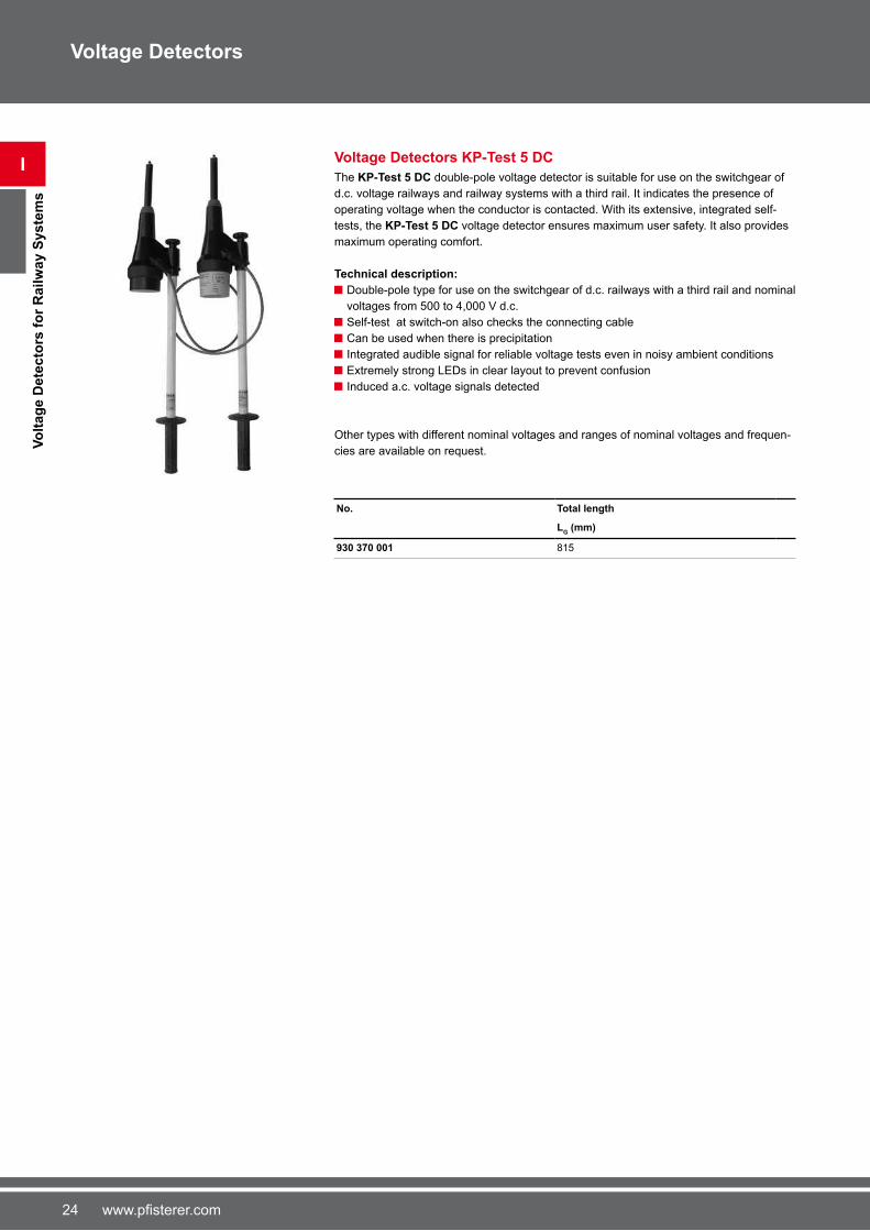
Voltage Detectors KP-Test 5 DC
The KP-Test 5 DC double-pole voltage detector is suitable for use on the switchgear of
d.c. voltage railways and railway systems with a third rail. It indicates the presence of
operating voltage when the conductor is contacted. With its extensive, integrated self-
tests, the KP-Test 5 DC voltage detector ensures maximum user safety. It also provides
maximum operating comfort.
Technical description:
Double-pole type for use on the switchgear of d.c. railways with a third rail and nominal
voltages from 500 to 4,000 V d.c.
Self-test at switch-on also checks the connecting cable
Can be used when there is precipitation
Integrated audible signal for reliable voltage tests even in noisy ambient conditions
Extremely strong LEDs in clear layout to prevent confusion
Induced a.c. voltage signals detected
Other types with different nominal voltages and ranges of nominal voltages and frequen-
cies are available on request.
No. Total length
LG (mm)
930 370 001 815
25www.pfisterer.com
I
Insu
lati
ng
Po
les f
or
Vo
ltag
e D
ete
cto
rs
Voltage Detectors
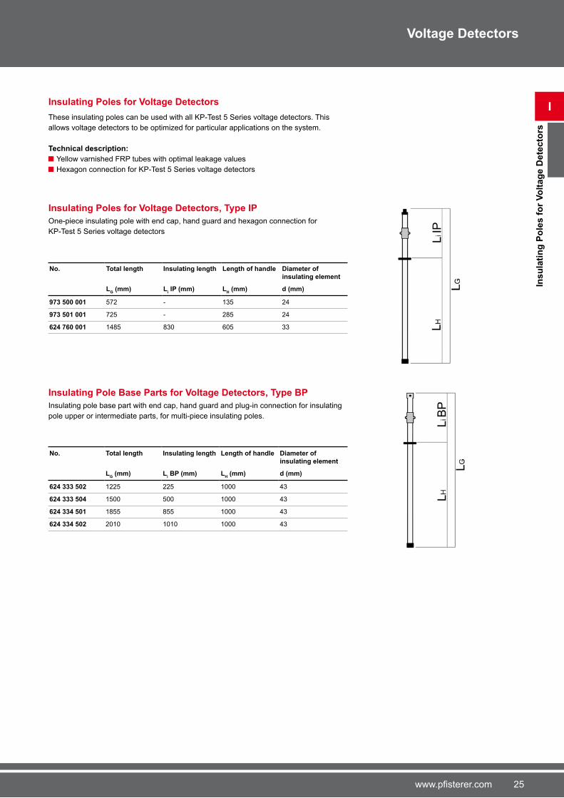
Insulating Poles for Voltage Detectors
These insulating poles can be used with all KP-Test 5 Series voltage detectors. This
allows voltage detectors to be optimized for particular applications on the system.
Technical description:
Yellow varnished FRP tubes with optimal leakage values
Hexagon connection for KP-Test 5 Series voltage detectors
Insulating Poles for Voltage Detectors, Type IP
One-piece insulating pole with end cap, hand guard and hexagon connection for
KP-Test 5 Series voltage detectors
No. Total length Insulating length Length of handle Diameter of
insulating element
LG (mm) L
i IP (mm) L
H (mm) d (mm)
973 500 001 5�2 - 135 24
973 501 001 �25 - 285 24
624 760 001 1485 830 �05 33
Insulating Pole Base Parts for Voltage Detectors, Type BP
Insulating pole base part with end cap, hand guard and plug-in connection for insulating
pole upper or intermediate parts, for multi-piece insulating poles.
No. Total length Insulating length Length of handle Diameter of insulating element
LG (mm) L
i BP (mm) L
H (mm) d (mm)
624 333 502 1225 225 1000 43
624 333 504 1500 500 1000 43
624 334 501 1855 855 1000 43
624 334 502 2010 1010 1000 43

2� www.pfisterer.com
I
Insu
lati
ng
Po
les f
or
Vo
ltag
e D
ete
cto
rs
Voltage Detectors
Insulating Pole Upper Parts for Voltage Detectors, Type UP
Insulating pole upper part for multi-piece insulating poles. With hexagon connection for
KP-Test 5 Series voltage detectors.
No. Total length Insulating length Diameter of
insulating element
LG (mm) L
i UP (mm) d (mm)
624 780 002 9�� 802 33
624 780 001 2050 18�5 33
Insulating Pole Intermediate Parts for Voltage Detectors, Type EP
Insulating pole intermediate part for multi-piece insulating poles. Plugs in between insula-
ting pole upper part and base part.
No. Total length Insulating length Diameter of insulating element
LG (mm) L
i EP (mm) d (mm)
624 336 501 1100 9�5 43
624 336 002 3130 3005 43
Insulating Pole Extensions for Voltage Detectors
This insulating pole extension makes it simple to extend the PFISTERER insulating poles
of voltage detectors. The insulating pole extension is screwed onto the existing insulating
pole. This does not reduce the minimum insulation length.
These insulation pole extensions can be used for:
KP-Test 5
KP-Test 5 dual
KP-Test 5L
KP-Test 5L dual
No. Total length Diameter of insulating element
LG (mm) d (mm)
620 518 002 5�0 24
620 518 001 10�0 24

2�www.pfisterer.com
Voltage Detectors
I
Insu
lati
ng
Po
les f
or
Vo
ltag
e D
ete
cto
rs
Insulating Poles for Voltage Detectors KP-Test 5 and 5H
Minimum length of insulating elements Li by standard EN �1243-1
Ur
Li
(kV) (mm)
1 < Ur ≤ 36 520
36 < Ur ≤ 72,5 830
72,5 < Ur ≤ 123 1300
123 < Ur ≤ 170 1�00
170 < Ur ≤ 245 2300
245 < Ur ≤ 420 3�00
Ur = rating voltage

28 www.pfisterer.com
I
Insu
lati
ng
Po
les f
or
Railw
ay V
olt
ag
e D
ete
cto
rs
Voltage Detectors
Insulating Poles for Railway Voltage Detectors
This insulating poles are applicable to all KP-Test 5R voltage detectors series. Optimal
way for laying out voltage detectors for respective applications.
Technical description:
Hexagon connection for KP-Test 5 Series voltage detectors
Yellow, respectively white varnished FRP tubes with optimal leakage values
Insulating Pole Base Parts for Three-part Voltage Detectors, Type RP1
Insulating pole base part with end cap, hand guard and plug-in connection for insulating
pole upper parts UP.
No. Total length Insulating length Length of handle Diameter of insulating element
LG (mm) L
i RP1 (mm) L
H (mm) d (mm)
620 780 002 1950 480 14�5 33
620 780 001 2450 480 19�5 33
Insulating Pole Base Parts for Five-part Voltage Detectors, Type RP2
Insulating pole base part with end cap, hand guard and plug-in connection for insulating
pole intermediate parts RP3.
No. Total length Length of handle Diameter of
insulating element
LG (mm) L
H RP2 (mm) d (mm)
623 930 001 1080 955 43
29www.pfisterer.com
I
Insu
lati
ng
Po
les f
or
Railw
ay V
olt
ag
e D
ete
cto
rs
Voltage Detectors
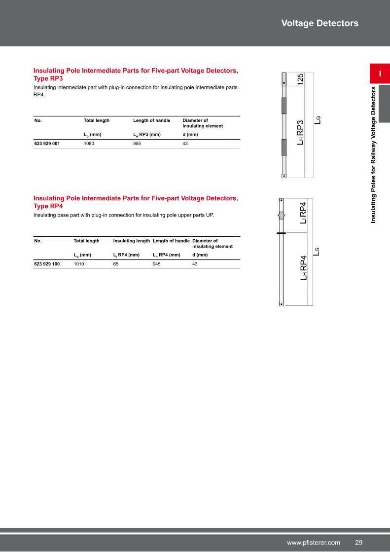
Insulating Pole Intermediate Parts for Five-part Voltage Detectors, Type RP3
Insulating intermediate part with plug-in connection for insulating pole intermediate parts
RP4.
No. Total length Length of handle Diameter of
insulating element
LG (mm) L
H RP3 (mm) d (mm)
623 929 001 1080 955 43
Insulating Pole Intermediate Parts for Five-part Voltage Detectors, Type RP4
Insulating base part with plug-in connection for insulating pole upper parts UP.
No. Total length Insulating length Length of handle Diameter of insulating element
LG (mm) L
i RP4 (mm) L
H RP4 (mm) d (mm)
623 929 100 1010 �5 945 43

30 www.pfisterer.com
Voltage Detectors
Insulating Poles for Voltage Detectors KP-Test 5R DC and KP-Test 5R DC dual
I
Insu
lati
ng
Po
les f
or
Railw
ay V
olt
ag
e D
ete
cto
rs Minimum length of insulating elements Li

31www.pfisterer.com
I
In-s
erv
ice T
ests
fo
r V
olt
ag
e D
ete
cto
rs
Voltage Detectors
In-service Tests for Voltage Detectors
Depending on national regulations in the country concerned, in-service tests are required
for voltage detectors with nominal voltages above 1 kV. In Germany, these are obligatory
under the „Electrical installations and equipment“ (BGV A3) accident prevention rule.
Voltage detectors must then, within a maximum period of six years, be submitted to ano-
ther in-service test and specified checks. The appendix of Standard IEC 61243-1 gives a description of these tests.
PFISTERER have been successfully carrying out these in-service tests on their own test
equipment for many years. The voltage detectors are tested according to the specifica-
tions, and immediately adjusted if necessary. Whenever extensive repairs are necessary,
we give a cost quotation.
When the tests are completed, the results are documented in detail.
To request an In-service test, please contact your local sales agency.
For customers in Germany please use the following mailing address:
PFISTERER Kontaktsysteme GmbH & Co. KG
Bereich Wiederholungsprüfung
Bahnhofstraße 30
8954� Gerstetten - Gussenstadt
Germany
No. Description
200 000 001 KP-Test II
200 000 002 KP-Test III
200 000 003 KP-GLI
200 000 004 KP-Test II Railway
200 000 005 KP-Test II USE
200 000 006 Testing set
200 000 014 SONIC signal application
200 000 200 KP-Test 5
32 www.pfisterer.com
II
Sin
gle
-po
le P
hase C
om
para
tors
Phase Comparators
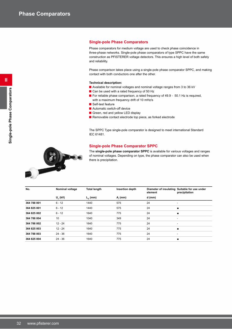
Single-pole Phase Comparators
Phase comparators for medium voltage are used to check phase coincidence in
three-phase networks. Single-pole phase comparators of type SPPC have the same
construction as PFISTERER voltage detectors. This ensures a high level of both safety
and reliability.
Phase comparison takes place using a single-pole phase comparator SPPC, and making
contact with both conductors one after the other.
Technical description:
Available for nominal voltages and nominal voltage ranges from 3 to 3� kV
Can be used with a rated frequency of 50 Hz
For reliable phase comparison, a rated frequency of 49.9 - 50.1 Hz is required,
with a maximum frequency drift of 10 mHz/s
Self-test feature
Automatic switch-off device
Green, red and yellow LED display
Removable contact electrode top piece, as forked electrode
The SPPC Type single-pole comparator is designed to meet international Standard
IEC �1481.
Single-pole Phase Comparator SPPC
The single-pole phase comparator SPPC is available for various voltages and ranges
of nominal voltages. Depending on type, the phase comparator can also be used when
there is precipitation.
No. Nominal voltage Total length Insertion depth Diameter of insulating element
Suitable for use under precipitation
Un (kV) L
G (mm) A
i (mm) d (mm)
364 788 001 � - 12 1440 5�5 24 -
364 825 001 � - 12 1440 5�5 24 ■
364 825 002 � - 12 1�40 ��5 24 ■
364 788 004 10 1040 349 24 -
364 788 002 12 - 24 1�40 ��5 24 -
364 825 003 12 - 24 1�40 ��5 24 ■
364 788 003 24 - 3� 1�40 ��5 24 -
364 825 004 24 - 3� 1�40 ��5 24 ■
33www.pfisterer.com
II
Sin
gle
-po
le P
hase C
om
para
tors
Phase Comparators
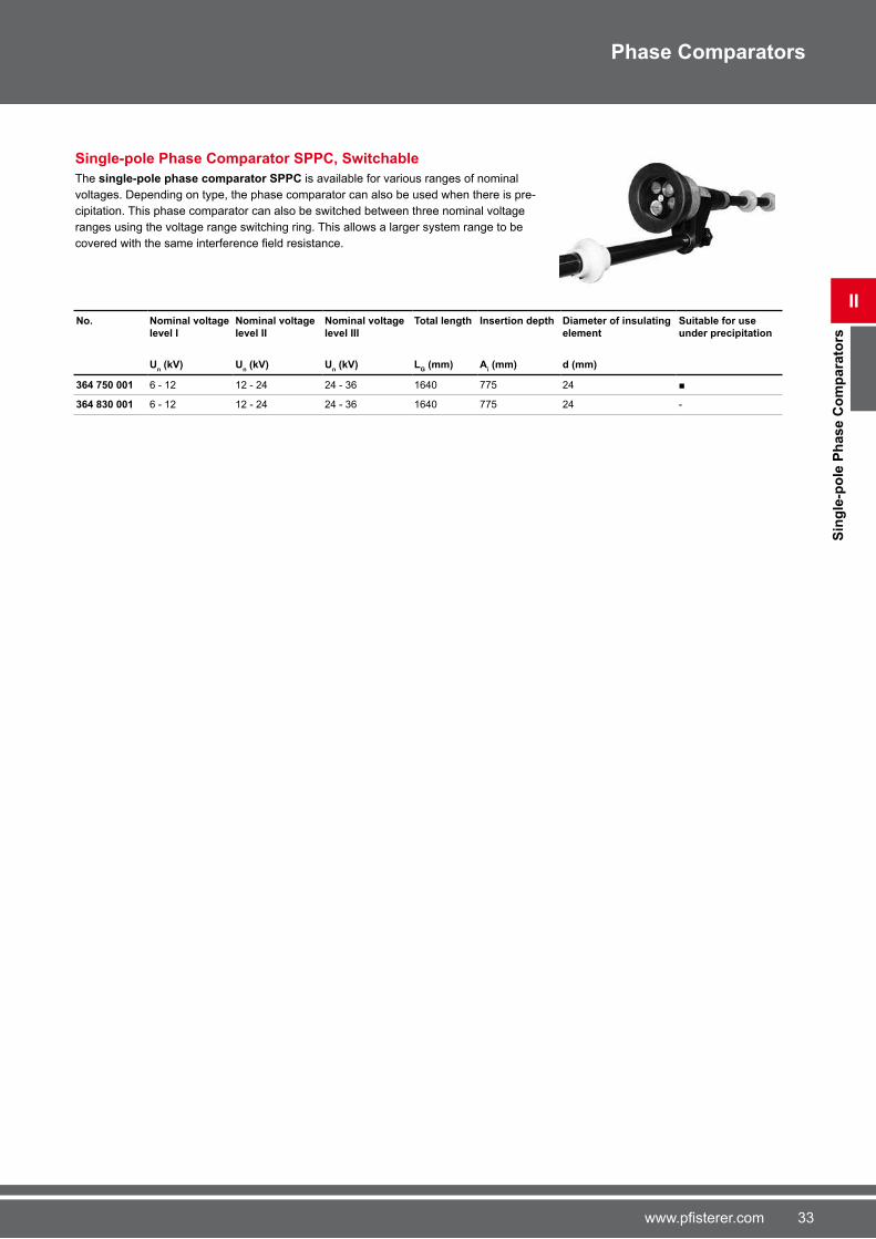
Single-pole Phase Comparator SPPC, Switchable
The single-pole phase comparator SPPC is available for various ranges of nominal
voltages. Depending on type, the phase comparator can also be used when there is pre-
cipitation. This phase comparator can also be switched between three nominal voltage
ranges using the voltage range switching ring. This allows a larger system range to be
covered with the same interference field resistance.
No. Nominal voltage
level I
Nominal voltage
level II
Nominal voltage
level III
Total length Insertion depth Diameter of insulating
element
Suitable for use
under precipitation
Un (kV) U
n (kV) U
n (kV) L
G (mm) A
i (mm) d (mm)
364 750 001 � - 12 12 - 24 24 - 3� 1�40 ��5 24 ■
364 830 001 � - 12 12 - 24 24 - 3� 1�40 ��5 24 -
34 www.pfisterer.com
II
Delt
am
ete
r 5
Phase Comparators
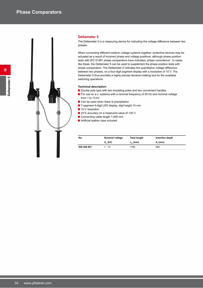
Deltameter 5
The Deltameter 5 is a measuring device for indicating the voltage difference between two
phases.
When connecting different medium voltage systems together, protective devices may be
actuated as a result of incorrect phase and voltage positions, although phase position
tests with IEC �1481 phase comparators have indicated „phase coincidence“. In cases
like these, the Deltameter 5 can be used to supplement the phase position tests with
phase comparators. The Deltameter 5 indicates the quantitative voltage difference
between two phases, on a four-digit segment display with a resolution of 10 V. The
Deltameter 5 thus provides a highly precise decision-making tool for the available
switching operations.
Technical description:
Double pole type with two insulating poles and two convenient handles
For use on a.c. systems with a nominal frequency of 50 Hz and nominal voltage
from 1 to 13 kV
Can be used when there is precipitation
�-segment 4-digit LED display, digit height 14 mm
10 V resolution
±5 % accuracy on a measured value of +30 V
Connecting cable length 1,000 mm
Artificial leather case included
No. Nominal voltage Total length Insertion depth
Un (kV) L
G (mm) A
i (mm)
930 450 001 1 - 13 1190 520

35www.pfisterer.com
II
In-s
erv
ice
Te
sts
fo
r P
hase C
om
para
tors
Phase Comparators
In-service Tests for Phase Comparators
Depending on national regulations in the country concerned, in-service tests are required
for phase comparators with nominal voltages above 1 kV. In Germany, these are obli-
gatory under the „Electrical installations and equipment“ (BGV A3) accident prevention
rule. Voltage detectors must then, within a maximum period of six years, be submitted to
another in-service test and specified checks. The appendix of Standard IEC 61481 gives a description of these tests.
PFISTERER have been successfully carrying out these in-service tests on their own test
equipment for many years. The voltage detectors are tested according to the specifica-
tions, and immediately adjusted if necessary. Whenever extensive repairs are necessary,
we give a cost quotation.
When the tests are completed, the results are documented in detail.
To request an In-service test, please contact your local sales agency.
For customers in Germany please use the following mailing address:
PFISTERER Kontaktsysteme GmbH & Co. KG
Bereich Wiederholungsprüfung
Bahnhofstraße 30
8954� Gerstetten - Gussenstadt
Germany
No. Description
200 000 012 Double-pole phase comparators
200 000 016 Phase comparator SPPC - single-range
200 000 017 Phase comparator SPPC - multi-range
3� www.pfisterer.com
Ins
ula
tin
g P
ole
s
III
Operating Poles
Operating Poles
PFISTERER offers various types of operating poles for different applications. Operating
poles are hand-held devices for operating and testing live components.
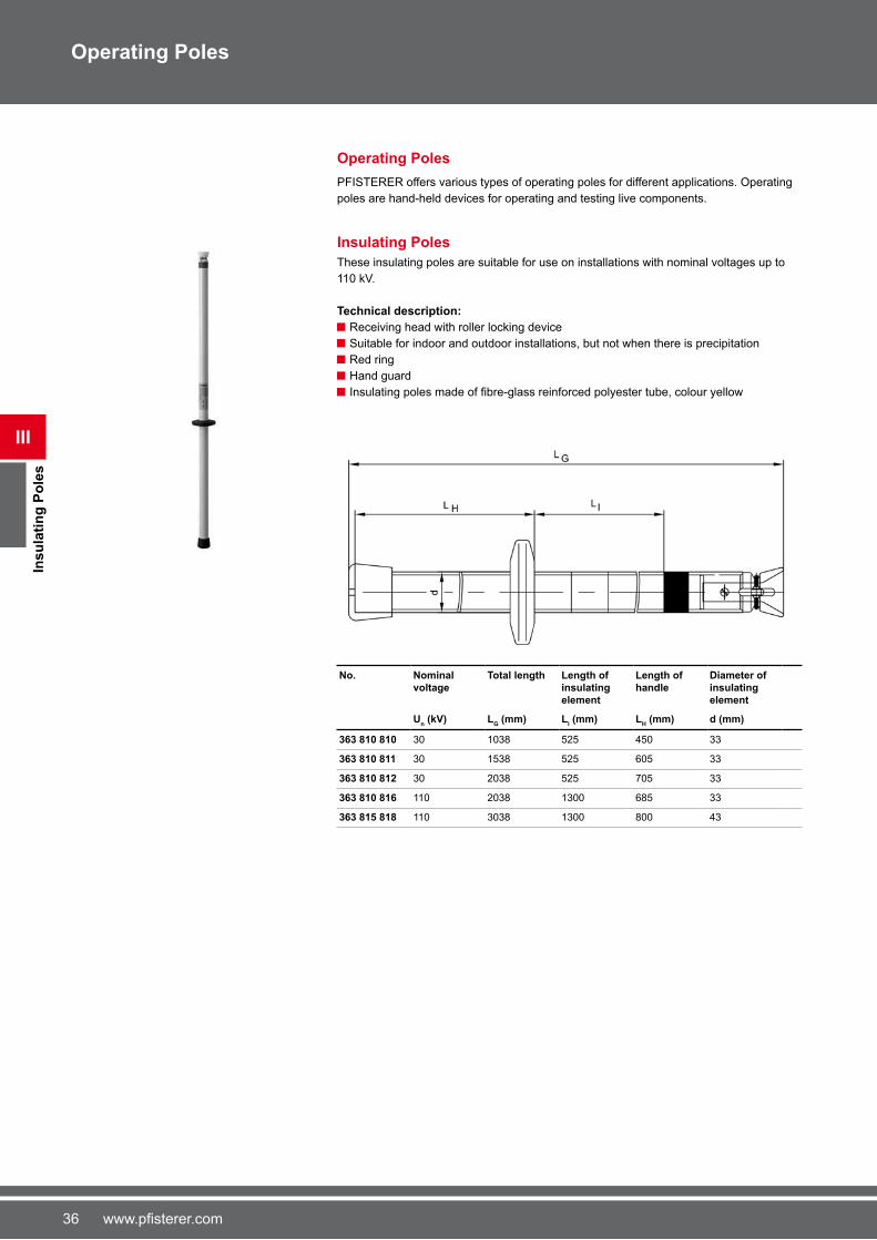
Insulating Poles
These insulating poles are suitable for use on installations with nominal voltages up to
110 kV.
Technical description:
Receiving head with roller locking device
Suitable for indoor and outdoor installations, but not when there is precipitation
Red ring
Hand guard
Insulating poles made of fibre-glass reinforced polyester tube, colour yellow
No. Nominal voltage
Total length Length of insulating element
Length of handle
Diameter of insulating element
Un (kV) L
G (mm) L
I (mm) L
H (mm) d (mm)
363 810 810 30 1038 525 450 33
363 810 811 30 1538 525 �05 33
363 810 812 30 2038 525 �05 33
363 810 816 110 2038 1300 �85 33
363 815 818 110 3038 1300 800 43
3�www.pfisterer.com
III
Ins
ula
tin
g P
ole
s
Operating Poles
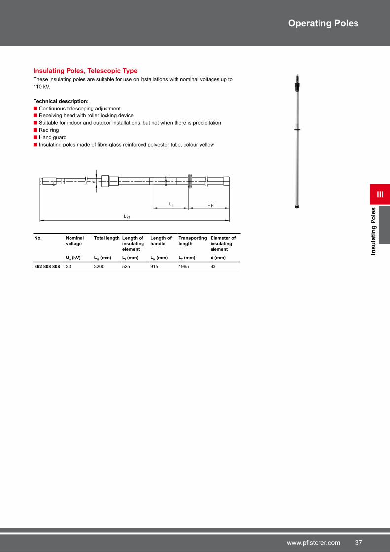
Insulating Poles, Telescopic Type
These insulating poles are suitable for use on installations with nominal voltages up to
110 kV.
Technical description:
Continuous telescoping adjustment
Receiving head with roller locking device
Suitable for indoor and outdoor installations, but not when there is precipitation
Red ring
Hand guard
Insulating poles made of fibre-glass reinforced polyester tube, colour yellow
No. Nominal voltage
Total length Length of insulating element
Length of handle
Transporting length
Diameter of insulating element
Un (kV) L
G (mm) L
I (mm) L
H (mm) L
T (mm) d (mm)
362 808 808 30 3200 525 915 19�5 43

38 www.pfisterer.com
Sw
itc
hin
g P
ole
s
III
Operating Poles
Switching Poles
These switching poles are suitable for use on installations with nominal voltages up to
110 kV.
Technical description:
Suitable for indoor and outdoor installations
Plastic actuating bolt and hand guard
End cap made of non-slip rubber
Switching pole made of glass-fibre reinforced polyester tube, colour yellow
These switching poles are designed to Standard DIN VDE 0�81 Part 1 and 2.
No. Nominal voltage
Suitable for use under precipitation
Total length Length of insulating element
Length of handle
Diameter of insulating element
Un (kV) L
G (mm) L
I (mm) L
H (mm) d (mm)
364 035 004 30 - 1008 525 400 33
364 827 006 30 ■ 1008 525 400 33
364 035 005 30 - 1508 525 530 33
364 827 001 30 ■ 1508 525 4�0 33
364 035 035 30 - 2008 525 �35 33
364 827 002 30 ■ 2008 525 4�0 33
364 035 036 30 - 2508 525 �50 33
364 035 037 30 - 3008 525 �50 33
364 827 003 �0 ■ 2508 900 850 33
364 035 042 110 - 2008 1300 �35 33
364 035 043 110 - 2508 1300 �50 33
364 827 004 110 ■ 3008 1300 950 33
364 035 008 110 - 3508 1300 �50 33
364 827 007 110 ■ 4008 1300 1400 33
364 827 008 110 ■ 5008 1300 1400 33

39www.pfisterer.com
III
Ins
ula
tin
g W
ork
ing
Po
les
Operating Poles
Insulating Working Poles
These insulating working poles are designed for use as operating poles on various jobs
carried out on or near live components.
Insulating working poles are available in various lengths. More details available on
request.
Pruning saw poles
Pruning saw poles used to saw off individual branches that have grown into the danger
area around electrical installations. For this purpose, special sawing devices are attached
to insulating poles made of fibre-glass reinforced polyester tube.
No. Version
360 488 000 0008
Lopping Poles
Lopping poles used to cutting off individual branches that have grown into the danger
area around electrical installations. For this purpose, special cutting devices are attached
to insulating poles made of fibre-glass reinforced polyester tube.
No. Version
360 488 000 0009
Ice-removing Poles
Ice-removing poles used to remove ice from electrical installations. For this purpose, a
special hook is attached to insulating poles made of fibre-glass reinforced polyester tube.
No. Version
360 488 000 0010
Cable Pulling Hook
This cable pulling hook is used for moving live superflexible cables, especially in mining applications.
No.
362 000 001

40 www.pfisterer.com
Ins
ula
tin
g W
ork
ing
Po
les
III
Operating Poles
All-insulated Rescue Hook
For rescuing persons from the danger area around live system components after an ac-
cident. These rescue hooks have a dielectric strength of 80 kV / mm. Type H is for indoor
use only, Type N can be used either in indoor or outdoor installations.
No. Type Range of application Length
(mm)
360 491 001 N < 1000 V 1000
360 491 002 H < 30000 V 1�50

41www.pfisterer.com
III
Fu
se
To
ng
s
Operating Poles
Fuse-tongs, 20° angled
This fuse-tong is suitable for replacing high-voltage fuses in switchgear.
Technical description:
Rapid adjustment using the double-threaded spindle
Tilted clamping jaws
Mechanical overload coupling protects the head from fracture
Not to be used when there is precipitation
The fuse tong is designed to Standard DIN VDE 0�81 Parts 1 and 3.
No. Nominal
voltage
Total length Length of
insulating
element
Length of
handle
Diameter of
insulating
element
Un (kV) L
G (mm) L
I (mm) L
H (mm) d (mm)
363 280 002 30 1251 525 4�0 33

42 www.pfisterer.com
Ea
rth
ing
Po
les
IV
Earthing Poles
Earthing Poles
Earthing poles are used for connecting earthing and short-circuiting devices. To do this,
the line clamps are brought up to the connection point on the dead conductor.
Technical description:
Line clamps held by spindle and cross-pin
A receiving head with roller locking device allows the earthing pole to be easily
attached/detached from the line clamp
Earthing poles made of glass-fibre reinforced polyester tube, coloured yellow Black mark indicates the required insulation gap
End cap made of non-slip rubber
Earthing Poles
Single-piece earthing poles.
No. Pole length Diameter of insulating
element
(mm) d (mm)
364 153 153 1038 33
364 153 154 1538 33
364 153 155 2038 33
364 156 156 2538 43
364 156 157 3038 43
364 156 158 3538 43
Telescopic Earthing Poles
Telescopic earthing poles.
No. Pole length extended Transporting length Diameter of insulating
element
L (mm) LT (mm) d (mm)
364 169 169 15�5 890 43
364 169 170 2030 1155 43
364 169 171 24�4 1390 43
364 169 172 2905 1540 43
364 169 173 3405 1�90 43
364 169 174 3905 2040 43
364 169 175 4415 2540 43
364 169 597 591� 4040 43

43www.pfisterer.com
IV
Ea
rth
ing
Po
les
Earthing Poles
Earthing Poles with Line Clamp P1
Single-piece earthing poles with fixed line clamp P1.The one-piece design allows earth fittings to be attached/detached easily, even in places that are difficult to access. The yellow earthing poles also clearly mark the work location.
No. Pole length Diameter of insulating
element
(mm) d (mm)
364 115 001 1500 33
Earthing Poles with Line Clamp P7
Single-piece earthing poles with fixed line clamp P7.The one-piece design allows earth fittings to be attached/detached easily, even in places that are difficult to access. The yellow earthing poles also clearly mark the work location.
No. Pole length Diameter of insulating element
(mm) d (mm)
364 212 001 2500 43
Telescopic Earthing Poles with Line Clamp P9
Earthing poles, telescopic type, with fixed parallel line clamp P9.This design allows earth fittings to be attached/detached easily, even in places that are difficult to access. The yellow earthing poles also clearly mark the work location.
No. Pole length extended Transporting length Diameter of insulating element
L (mm) LT (mm) d (mm)
364 084 084 2185 14�0 43
364 084 086 3050 1845 43
364 084 087 3540 2095 43
364 084 001 4040 2345 43
364 084 089 45�0 2845 43
364 084 002 �0�5 4190 43

44 www.pfisterer.com
Ea
rth
ing
Po
les
IV
Earthing Poles
Telescopic Earthing Poles with Line Clamp P8
Earthing poles, telescopic type, with fixed HV line clamp P8.This design allows earth fittings to be attached/detached easily, even in places that are difficult to access. The yellow earthing poles also clearly mark the work location.
No. Pole length extended Transporting length Diameter of insulating
element
L (mm) LT (mm) d (mm)
364 112 114 3050 1�00 43
364 112 115 3540 1950 43
364 112 116 3950 2200 43
364 112 003 44�0 2�00 43
364 112 004 ��50 3�85 43

45www.pfisterer.com
IV
Ea
rth
ing
Po
les
Earthing Poles
Two-piece Earthing Poles with Phase Fixed Point
This two-piece earthing pole with downward aluminium phase fixed point makes it
easier to attach earthing and short-circuiting devices at high working positions on outdoor
switchgear.
This two-piece earthing pole is attached to the phase fixed point, tube or wire, and then tightened. The earthing pole remains attached throughout the whole earthing process. A
single-pole earthing and short-circuiting device with separate earthing pole can then be
attached to the downward phase fixed point on the two-piece earthing pole.
Technical description:
The earthing and short-circuiting device can be used for short-circuit currents
up to 29.5 kA / 1 s (wire cross-section 150 mm2)
Working heights up to 9 m possible
Easy handling thanks to shorter ground wire
Shorter, weight-saving ground wire
The earthed working location is very clearly marked by the attached earthing pole
Aluminium downward fixed phase point Suitable earthing poles:
3�4 112 115 (with line clamp P8)
3�4 1�9 1�3 (without line clamp)
Diameter of insulating part: 43 mm
Earthing device to connect phase fixed point to ground potential need to be ordered separately.
1
2
No. Version Total length Carrying length Line clamp
LG (mm) (mm)
364 116 000 0001 4500 310� P� 1
364 116 000 0002 5000 310� P� 1
364 116 000 0003 5500 310� P� 1
364 116 000 0004 �000 310� P� 1
364 116 000 0005 �500 3494 P� 1
364 116 000 000� �000 3494 P� 1
364 116 000 000� �500 4494 P� 1
364 116 000 0008 8000 4494 P� 1
364 116 000 0010 4500 310� P8 2
364 116 000 0011 5000 310� P8 2
364 116 000 0012 5500 310� P8 2
364 116 000 0013 �000 310� P8 2
364 116 000 0014 �500 3501 P8 2
364 116 000 0015 �000 4001 P8 2
364 116 000 001� �500 4501 P8 2
364 116 000 001� 8000 5001 P8 2

4� www.pfisterer.com
Ea
rth
ing
Po
les
fo
r R
ailw
ay
Sy
ste
ms
IV
Earthing Poles
Earthing Poles for Railway Systems
Earthing poles for railway systems are used for connecting railway grounding devices. To
do this, the earthing terminals are brought up to the contact wire. These earthing poles
are marked with red stripes on a white background. This allows optimum identification of the work location.
Technical description:
Contact wire earthing terminals held by spindle and cross-pin
A receiving head with roller locking device allows the earthing pole to be
easily attached/detached from the contact wire earthing terminal
Robust construction for use in railway applications
Telescopic Earthing Poles, two-piece
Earthing poles for railway systems, in two-piece design. These earthing poles are used
mainly for transformers and railway power lines. They are continuously adjustable.
No. Length range
Pole length extended
Transporting length
Insulating length
Weight DB no. DB drawing number
(m) L (mm) LT (mm) L
I (mm) (kg)
362 744 001 1,8 - 3,0 3500 1800 500 3.8 0015�50� 3 Ebgw 01.1�
362 744 744 2,� - 5,0 5000 2�00 500 3.8 0015�49� 3 Ebgw 01.12
Telescopic Earthing Poles, three-piece
Earthing poles for railway systems, in three-piece design. The top area of the earthing
pole is continuously adjustable.
The connection between the earthing pole and the contact wire earthing terminal can be
fixed using a slider. The earthing pole can thus be used to mark the work location.
No. Length range Pole length
extended
Transporting
length
Insulating
length
Weight
(m) L (mm) LT (mm) L
I (mm) (kg)
362 745 745 2,0 - 5,0 5080 2000 500 5.2
362 745 002 3,2 - �,0 �000 3200 500 5.2

4�www.pfisterer.com
IV
Ea
rth
ing
Po
les
fo
r R
ailw
ay
Sy
ste
ms
Earthing Poles
Earthing Poles, five-piece
Earthing pole for railway systems in five-piece design. Because of the short carrying length, this type is suitable for transport in all common passenger vehicle types.
The connection between the earthing pole and the contact wire earthing terminal can be
fixed using a slider. The earthing pole can thus be used to mark the work location.
No. Length
range
Pole length Transporting
length
Insulating
length
DB no. DB drawing
number
(m) L (mm) LT (mm) L
I (mm)
364 784 001 4,9 4892 1100 500 0015�498 3 Ebgw 01.22

48 www.pfisterer.com
V
Eart
hin
g a
nd
Sh
ort
-cir
cu
itin
g D
ev
ice
s
Earthing and Short-circuiting Devices
Earthing and Short-circuiting Devices
When working on electrical switchgear, earthing and short-circuiting devices are es-
sential components for ensuring user safety and protecting the switchgear. For earthing,
and to set up a temporary short-circuit-proof link to parts of the switchgear, you also need
tools that meet the highest quality and reliability requirements.
PFISTERER has been developing and producing earthing and short-circuiting devices
for decades, and symbolises this kind of quality and reliability. Through an optimised
process, we are able to supply the widest variety of types of earthing and short-circuiting
devices.
Technical description:
Earthing and short-circuiting devices for short-circuit currents from 4.9 to 29.� kA/s
Copper earthing and short-circuiting cables can be supplied with cross-section
from 25 mm2 to 150 mm2
Individual conductors can be replaced by the appropriate connecting cluster
Optimised protection from damage and atmospheric influences on cable ends Components suitable for different types of application
Components dimensioned for high short-circuit currents
Our earthing and short-circuiting devices are made extensively to IEC �1230 standard,
and type-tested on approved test equipment.
Our earthing and short-circuiting devices are available in four basic types:
Single-pole earthing and sort-circuiting device
Double-pole earthing and short-circuiting device with two short-circuiting cables and
one earthing cable
Three-pole earthing and short-circuiting device with three short-circuiting cables and
one earthing cable
Four-pole earthing and short-circuiting device with four short-circuiting cables and
one earthing cable
Cross-section of
copper conductor
mm2 10 s 5 s 2 s 1 s ≤ 0.5 s25 1�00 2200 3500 4900 �000
35 2200 3100 4900 �900 10000
50 3100 4400 �000 9900 14000
�0 4400 �200 9800 13800 19500
95 5900 8400 13200 18�00 2�500
120 �500 10�00 1��00 23�00 33500
150 9400 13200 20900 29�00 42000
A few basic types are shown below, other variants with different cross-sections,
terminals and lengths are available on request.
Extremely reliable short-circuit current Ik indicated
in A for a period of
49www.pfisterer.com
Eart
hin
g a
nd
Sh
ort
-cir
cu
itin
g D
ev
ice
s
V
Earthing and Short-circuiting Devices
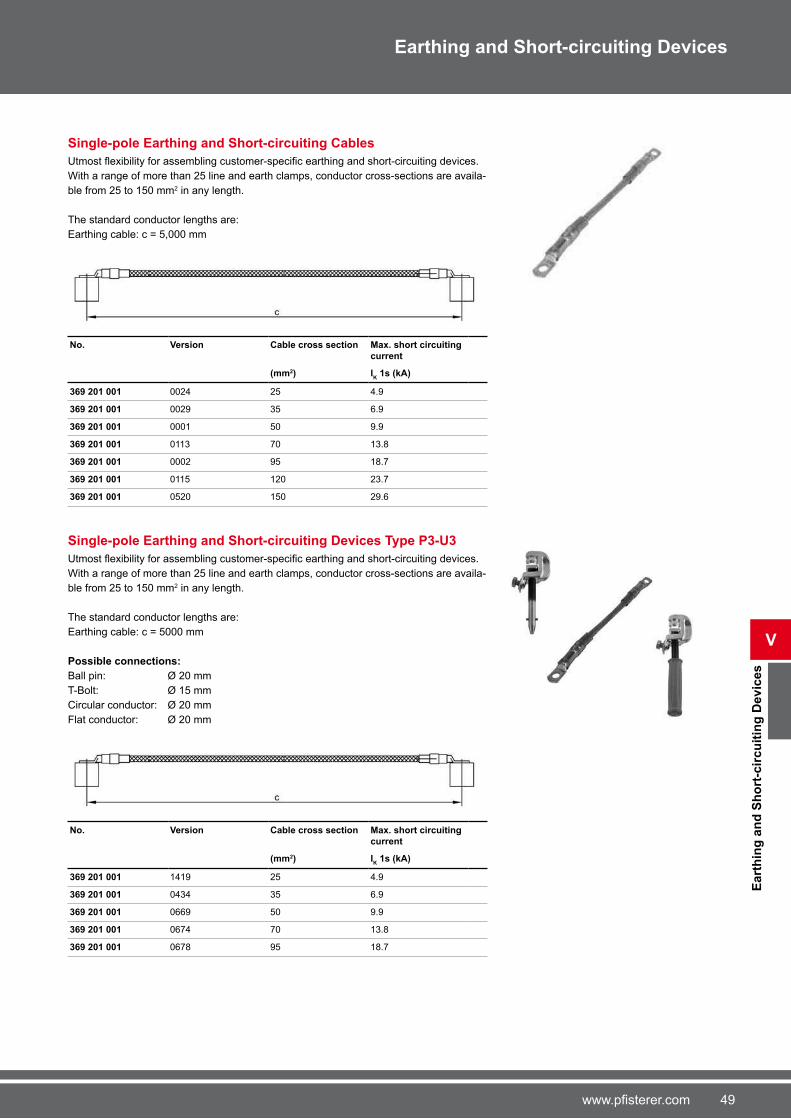
Single-pole Earthing and Short-circuiting Cables
Utmost flexibility for assembling customer-specific earthing and short-circuiting devices. With a range of more than 25 line and earth clamps, conductor cross-sections are availa-
ble from 25 to 150 mm2 in any length.
The standard conductor lengths are:
Earthing cable: c = 5,000 mm
No. Version Cable cross section Max. short circuiting
current
(mm2) IK 1s (kA)
369 201 001 0024 25 4.9
369 201 001 0029 35 �.9
369 201 001 0001 50 9.9
369 201 001 0113 �0 13.8
369 201 001 0002 95 18.�
369 201 001 0115 120 23.�
369 201 001 0520 150 29.�
Single-pole Earthing and Short-circuiting Devices Type P3-U3
Utmost flexibility for assembling customer-specific earthing and short-circuiting devices. With a range of more than 25 line and earth clamps, conductor cross-sections are availa-
ble from 25 to 150 mm2 in any length.
The standard conductor lengths are:
Earthing cable: c = 5000 mm
Possible connections:
Ball pin: Ø 20 mm
T-Bolt: Ø 15 mm
Circular conductor: Ø 20 mm
Flat conductor: Ø 20 mm
No. Version Cable cross section Max. short circuiting
current
(mm2) IK 1s (kA)
369 201 001 1419 25 4.9
369 201 001 0434 35 �.9
369 201 001 0��9 50 9.9
369 201 001 0��4 �0 13.8
369 201 001 0��8 95 18.�

50 www.pfisterer.com
V
Eart
hin
g a
nd
Sh
ort
-cir
cu
itin
g D
ev
ice
s
Earthing and Short-circuiting Devices
Single-pole Earthing and Short-circuiting Devices Type P5-U5
Utmost flexibility for assembling customer-specific earthing and short-circuiting devices. With a range of more than 25 line and earth clamps, conductor cross-sections are availa-
ble from 25 to 150 mm2 in any length.
The standard conductor lengths are:
Earthing cable: c = 5000 mm
Possible connections:
Ball pin: Ø 25 mm
T-Bolt: Ø 20 mm
Circular conductor: Ø 25 mm
Flat conductor: Ø 20 mm
No. Version Cable cross section Max. short circuiting current
(mm2) IK 1s (kA)
369 201 001 1421 25 4.9
369 201 001 0950 35 �.9
369 201 001 0�01 50 9.9
369 201 001 0�05 �0 13.8
369 201 001 014� 95 18.�
369 201 001 0�13 120 23.�

51www.pfisterer.com
Eart
hin
g a
nd
Sh
ort
-cir
cu
itin
g D
ev
ice
s
V
Earthing and Short-circuiting Devices
Three-pole Earthing and Short-circuiting Cables
Utmost flexibility for assembling customer-specific earthing and short-circuiting devices. With a range of more than 25 line and earth clamps, conductor cross-sections are availa-
ble from 25 to 150 mm2 in any length.
The standard conductor lengths are:
Short-circuiting cables: a = b = d = �00 mm
Earthing cable: c = 1,500 mm
No. Version Cable cross section Max. short circuiting
current
(mm2) IK 1s (kA)
369 203 001 00�2 25 / 25 4.9
369 203 001 1539 35 / 35 �.9
369 203 001 0020 50 / 25 9.9
369 203 001 00�� �0 / 35 13.8
369 203 001 00�� 95 / 35 18.�
369 203 001 0�9� 120 / 50 23.�
369 203 001 0�00 150 / 50 29.�

52 www.pfisterer.com
V
Eart
hin
g a
nd
Sh
ort
-cir
cu
itin
g D
ev
ice
s
Earthing and Short-circuiting Devices
Three-pole Earthing and Short-circuiting Devices Type P3-U3
Utmost flexibility for assembling customer-specific earthing and short-circuiting devices. With a range of more than 25 line and earth clamps, conductor cross-sections are availa-
ble from 25 to 150 mm2 in any length.
The standard conductor lengths are:
Short-circuiting cables: a = b = d = �00 mm
Earthing cable: c = 1,500 mm
Possible connections:
Ball pin: Ø 20 mm
T-Bolt: Ø 15 mm
Circular conductor: Ø 20 mm
Flat conductor: Ø 20 mm
No. Version Cable cross section Max. short circuiting current
(mm2) IK 1s (kA)
369 203 001 1245 25 / 25 4.9
369 203 001 0033 35 / 35 �.9
369 203 001 0829 50 / 25 9.9
369 203 001 0334 �0 / 35 13.8
369 203 001 0830 95 / 35 18.�

53www.pfisterer.com
Eart
hin
g a
nd
Sh
ort
-cir
cu
itin
g D
ev
ice
s
V
Earthing and Short-circuiting Devices
Three-pole Earthing and Short-circuiting Devices Type P5-U5
Utmost flexibility for assembling customer-specific earthing and short-circuiting devices. With a range of more than 25 line and earth clamps, conductor cross-sections are availa-
ble from 25 to 150 mm2 in any length.
The standard conductor lengths are:
Short-circuiting cables: a = b = d = �00 mm
Earthing cable: c = 1,500 mm
Possible connections:
Ball pin: Ø 25 mm
T-Bolt: Ø 20 mm
Circular conductor: Ø 25 mm
Flat conductor: Ø 25 mm
No. Version Cable cross section Max. short circuiting current
(mm2) IK 1s (kA)
369 203 001 1251 25 / 25 4.9
369 203 001 1252 35 / 35 �.9
369 203 001 02�0 50 / 25 9.9
369 203 001 0080 �0 / 35 13.8
369 203 001 00�� 95 / 35 18.�
369 203 001 0009 120 / 50 23.�

54 www.pfisterer.com
V
Eart
hin
g a
nd
Sh
ort
-cir
cu
itin
g D
ev
ice
s
Earthing and Short-circuiting Devices
Three-pole Earthing and Short-circuiting Devices Type P2-U5
No. Version Cable cross section Max. short circuiting
current
(mm2) IK 1s (kA)
369 203 001 1253 25 / 25 4.9
369 203 001 1254 35 / 35 �.9
369 203 001 1255 50 / 25 9.9
369 203 001 125� �0 / 35 13.8
369 203 001 125� 95 / 35 18.�
369 203 001 1258 120 / 50 23.�
Utmost flexibility for assembling customer-specific earthing and short-circuiting devices. With a range of more than 25 line and earth clamps, conductor cross-sections are
available from 25 to 150 mm2 in any length.
The standard conductor lengths are:
Short-circuiting cables: a = b = d = �00 mm
Earthing cable: c = 1,500 mm
Possible connections:
Line clamp:
circular conductor: Ø �-32 mm
Earth clamp:
Ball pin: Ø 25 mm
T-Bolt: Ø 20 mm
Circular conductor: Ø 25 mm
Flat conductor: Ø 25 mm
55www.pfisterer.com
Eart
hin
g a
nd
Sh
ort
-cir
cu
itin
g D
ev
ice
s
V
Earthing and Short-circuiting Devices
Earth Fittings for Medium Voltage Overhead Lines
This three-pole earthing and short-circuiting device is designed for use on medium
voltage overhead lines. The fixed earthing poles allow rapid attachment and removal of the line clamps and also mark the work location.
Technical description:
Three-pole earthing and short-circuiting device for use on medium voltage
overhead lines
Line clamps P1 are fixed to these earthing poles Length of short-circuiting cables: 1.5 m
Ground wire length: 11 m
Earth end can be connected to an earthing spike
No. Version Cable cross section Max. short circuiting
current
(mm2) IK 1s (kA)
369 203 001 103� 50 9.9

5� www.pfisterer.com
V
Eart
hin
g a
nd
Sh
ort
-cir
cu
itin
g D
ev
ice
s
Earthing and Short-circuiting Devices
Earthing and Short-circuiting Devices for Low Voltage
Our low-voltage earthing and short-circuiting devices are used in low-voltage over-
head lines and low-voltage switchgear, for example in cable distribution cabinets.
All-insulated Earthing and Short-circuiting Devices
This all-insulated earthing and short-circuiting device is designed for use on low voltage
overhead lines.
Technical description:
All-insulated suspension clamps for conductor Ø 314 mm
Suspension clamp with probe tip and LED indicator for voltage indication
Earthing and short-circuiting cables in �00 mm wire cable lengths
Glass-fibre reinforced polyester tubes in 500 and 800 mm tube lengths Transparent insulating handles with bending protection
Insulated screw-type connecting cluster
No. Cable cross section
Max. short-circuit current
Number of suspension clamps
Length of insulating rods
(mm2) Ik 1 s (A) (mm)
360 528 528 25 4900 4 3 x 500 + 1 x 800
360 528 529 25 4900 5 4 x 500 + 1 x 800
360 528 530 25 4900 � 5 x 500 + 1 x 800
All-insulated Earthing and Short-circuiting Devices with Line Clamp P1
This earthing and short-circuiting device is designed for use on low voltage overhead
lines with high short-circuit currents.
Technical description:
Line clamp P1 fixed to handle Handle for easy handling
No. Cable cross section
Max. short-circuit current
Number of suspension clamps
(mm2) Ik 1 s (A)
360 528 531 35 �900 5

5�www.pfisterer.com
Eart
hin
g a
nd
Sh
ort
-cir
cu
itin
g D
ev
ice
s
V
Earthing and Short-circuiting Devices
Earthing and Short-circuiting Devices for Low Voltage Distribution Boards
This earthing and short-circuiting device is designed for use on low-voltage distribution
boards, cable distribution cabinets and fuse boxes. It is supplied as a set, consisting of
the following components. Different contents available on request.
Technical description:
The set is made up of the following parts:
2 earthing and short-circuiting devices to standard DIN VDE 0�83 Part 100,
cable cross-section: 25 mm2
Cable lengths: a = 300 mm; b = �00 mm; c = 800 mm; d = 1000 mm
Screw-in thread for earthing cartridges, slotted cable lug for earth clamps
2 MP clamps for busbars with flexible handle and 2 spindle settings, 623 695 001 � earthing cartridges for NH size 1 – 3, 3�4809001
1 earthing pole (350 mm) for inserting the earthing cartridges, or attaching the earthing
and short-circuiting device
3 earthing inserts for DIAZED fuse holders, �23 �88 001
3 earthign cartridges for NH size 00, 3�4 �54 002
1 plastic carrying case with foam lining and user instructions, 3�4 558 001
No.
364 866 001
Three-pole Earthing and Short-circuiting Devices
With electromagnetic locking.
For low-voltage distributing boards and cable distribution cabinets with LV-HRC fuse rails
500 V, DIN 43 �23.
Technical description:
3 earthing cartridges with electromagnetic locking (size 1 to 3), 3�1 33� 33�
Earthing and short-circuiting cables with screw-type connecting cluster
Earth clamp type E2
Suitable earth handle 3�4 ��8 002 has to be ordered separately
No. Cable cross section
Cable length a
Cable length b
Cable length d
Cable length c
Weight
(mm2) (mm) (mm) (mm) (mm) (kg)
360 481 481 25 1000 �50 500 250 2.�

58 www.pfisterer.com
V
Sp
ec
ial E
art
h F
itti
ng
s
Earthing and Short-circuiting Devices
Special Earth Fittings
Besides the earthing and short-circuiting fittings for medium and high voltages, PFISTERER also offers special earth fittings for special applications.
Discharge Rods
Discharge rods are used for discharging induction and balance voltages from high
voltage capacitors.
Technical description:
Copper hook fixed to glass-fibre reinforced polyester tube, colour yellow Earthing cable with cable lug
Insulation length LI = 500 mm
Diameter of insulating element = 24 mm
Copper hook length = 120 mm
Copper hook diameter = 8 mm
Other types with other cable cross-sections and lengths are available on request.
No. Version Cable cross section
Cable length Pole length
(mm2) (mm) L (mm)
363 800 000 0003 25 2000 1000
363 800 000 0004 25 3000 1500

59www.pfisterer.com
Eart
hin
g a
nd
Sh
ort
-cir
cu
itin
g D
evic
es f
or
Ra
ilw
ay
Sy
ste
ms
V
Earthing and Short-circuiting Devices
Earthing Devices for Railway Systems
When working on the overhead lines of electric railways, you need earthing devices that
meet the highest quality and reliability requirements.
PFISTERER has been developing and producing earthing devices for railway systems
for decades, and symbolises this kind of quality and reliability. Through an optimised
process, we are able to supply the widest variety of types of earthing devices.
Technical description:
Earthing devices for long-distance railways with a.c. or d.c. voltage, for underground
railways and trolley lines
Copper earthing and short-circuiting cables available with cross-sections from
25 mm2 to 150 mm2
Earthing and short-circuiting devices available for profile-free earthing Optimised protection from damage and atmospheric influences on cable ends Components suitable for various types of application
Components dimensioned for high short-circuit currents
Railway Earthing Devices for Overhead Lines
This railway earthing device is designed for use on overhead lines. It can be used for
contact wire heights from 4.8 to 6.25 m. The use of rail earth clamp R50 allows profile-free earthing, and diesel locomotive operation is then possible in the earthed state.
Technical description:
Depending on type, this railway earthing device is made up of the following components:
1 contact wire earth clamp, 3�1 499 001
1 rail earth clamp, 3�3 322 005
1 earthing cable, 8.5 or 12 m long, 3�2 138 138
1 suspension hook, 3�0 453 453
1 telescopic type earthing pole (two-piece), 3�2 �44 �44
No. Description Length of earthing cable
Profile-free DB no. DB drawing number
(m)
364 845 001 with telescopic
earthing pole
2-piece
8.5 - 0023�111 3 Ebgw 01.11
364 845 006 without earth-
ing pole
8.5 - - -
364 845 002 with telescopic
earthing pole
2-piece and
suspension
hook for earth
wire
12 ■ 0023�112 3 Ebgw 01.11
364 845 005 without earth-
ing pole
with suspen-
sion hook for
earth wire
12 ■ - -

�0 www.pfisterer.com
V
Eart
hin
g a
nd
Sh
ort
-cir
cu
itin
g D
evic
es f
or
Ra
ilw
ay
Sy
ste
ms
Earthing and Short-circuiting Devices
Railway Earthing Devices for Overhead Lines (Automobile Type)
This railway earthing device is designed for mobile use and is suitable for transporting
in automobiles and vehicles of the emergency services or fire departments. The use of rail earth clamp R50 allows profile-free earthing, and diesel locomotive operation is then possible in the earthed state. The earthing pole and ratchet can be pulled off to mark the
work location.
Technical description:
Carrying length of the 5-piece earthing pole about 1,100 mm
Short-circuit-proof Ik = 3�.5 kA / 0.12 s
Depending on type, this railway earthing device is made up of the following components:
1 plug-in type earthing pole, No. 3�4 �84 001
2 rail earth clamps, No. 3�3 322 005
2 contact wire earth clamps, No. 3�1 499 001
2 short-circuiting cables 50 mm2, length 8.5 m or 12 m, with red marker flag 1 carryingcase for earthing pole, No 3�4 �8� 001
1 carrying case for 2 earthing sets, No. 3�4 �85 001
No. Description Length of earthing cable
Profile-free DB no. DB drawing number
(m)
364 766 001 with plug-in
type earthing
pole,
5-piece
8.5 - 0023�12� 3 Ebgw 01.21
364 766 004 with plug-in
type earthing
pole,
5-piece
12 ■ - -
Railway Earthing Devices for Railway Power Lines
This railway earthing device is designed for use on railway power lines.
Technical description:
It is made up of the following components:
1 Telescopic type earthing pole, two-piece, No. 3�2 �44 001
1 Earth clamp U2, No. 3�1 34� 001
1 contact wire earth clamp P50, with feeler bow, No. 3�3 418 003
1 short-circuiting cable 50 mm2, length 4 m
No. Length of earthing cable
DB no. DB drawing number
(m)
363 571 571 4 0023�10� 3 Ebgw 01.23
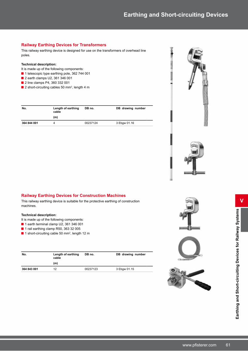
�1www.pfisterer.com
Eart
hin
g a
nd
Sh
ort
-cir
cu
itin
g D
evic
es f
or
Ra
ilw
ay
Sy
ste
ms
V
Earthing and Short-circuiting Devices
Railway Earthing Devices for Transformers
This railway earthing device is designed for use on the transformers of overhead line
poles.
Technical description:
It is made up of the following components:
1 telescopic type earthing pole, 3�2 �44 001
2 earth clamps U2, 3�1 34� 001
2 line clamps P4, 3�0 332 001
2 short-circuiting cables 50 mm2, length 4 m
No. Length of earthing
cable
DB no. DB drawing number
(m)
364 844 001 4 0023�124 3 Ebgw 01.1�
Railway Earthing Devices for Construction Machines
This railway earthing device is suitable for the protective earthing of construction
machines.
Technical description:
It is made up of the following components:
1 earth terminal clamp U2, 3�1 34� 001
1 rail earthing clamp R50, 3�3 32 005
1 short-circuiting cable 50 mm2, length 12 m
No. Length of earthing
cable
DB no. DB drawing number
(m)
364 843 001 12 0023�123 3 Ebgw 01.15

�2 www.pfisterer.com
Earthing and Short-circuiting Devices
Overview Earth Clamps
No. Type Max.
cross
section
Max. short-
circuit
current
Clamping
range
Clamping
width
Weight
(mm2) Ø (mm) Ø (mm) Ø (mm) Ø (mm) Ø (mm) lk 1 s (kA) (mm) (mm) (g)
364 811 001 A1 150 - 1� - - - 29.� 1� - �5�
364 544 002 A2 150 - 1� - 22 - 1� - 22 - 29.� 1� - 22 - �3�
360 419 004 E2 �0 - - - 2 - 30 2 - 30 13.8 2 - 30 - 3�0
360 416 002 F1 50 - - - - 2 - 20 9.9 2 - 20 - 442
360 628 002 F2 95 - - - - 2 - 22 18.� 2 - 22 - 9�8
360 414 001 U1 95 20 - 15 5 - 20 2 - 20 18.� 2 - 20 38 �20
361 346 001 U2 150 25 - 15 5 - 20 2 - 20 29.� 2 - 20 38 �54
364 704 004 U3 95 20 - 15 5 - 20 2 - 20 18.� 2 - 20 38 80�
364 704 003 U4 150 25
- 15 5 - 20 2 - 20 29.� 2 - 20 38 83�
364 714 002 U5 120 25
- 20 5 - 25 2 - 25 23.� 2 - 25 38 902
361 657 001 M12 150 -
- - - - 29.� - - 210
361 658 001 M1� 150 -
- - - - 29.� - - 210
361 657 002 S12 150 -
- - - - 29.� - - 250
361 659 001 S1� 150 -
- - - - 29.� - - 250
V
Ea
rth
Cla
mp
s

�3www.pfisterer.com
Earthing and Short-circuiting Devices
Overview Line Clamps
No. Type Max.
cross section
Max. short-
circuit current
Clamping
range
Clamping
width
Weight
(mm2) Ø (mm) Ø (mm) Ø (mm) Ø (mm) Ø (mm) lk 1 s (kA) (mm) (mm) (g)
364 904 001 P1 120 - - - 4 - 20 - 23.� 4 - 20 48 382
364 903 001 P2 150 - - - � - 32 - 29.� � - 32 5� 52�
360 330 002 P3 95 20 5 - 20 15 5 - 20 5 - 20 18.� 5 - 20 38 �54
360 332 001 P4 120 25 5 - 20 15 5 - 20 5 - 20 23.� 5 - 20 38 �82
360 333 002 P5 150 25 5 - 25 20 5 - 25 5 - 20 29.� 5 - 25 50 850
364 309 005 P� �0 - - - 4 - 23 4 - 23 13.8 4 - 23 2� 440
363 245 006 P� 120 - - - 4.5 - 35 4.5 - 35 23.� 4.5 - 35 34 �14
364 459 009 P8 150 - - - 10 - 85 - 29.� 10 - 85 40 88�
360 335 003 P9 95 -
- - 10 - 32 10 - 32 18.� 10 - 32 38 9�8
360 329 001 P10 50 -
- - 5 - 1� 5 - 1� 9.9 5 - 1� 40 �22
360 335 004 P11 95 -
- - 10 - 32 10 - 32 18.� 10 - 32 38 1010
363 091 297 P12 150 - - - - 10 - 25 29.� 10 - 25 40 914
Lin
e C
lam
ps
V

�4 www.pfisterer.com
Earthing and Short-circuiting Devices
V
Overview Contact Wire Earth Clamps for Railway Systems
No. Type Max. cross section
Max. short-circuit current
Clamping range
Clamping width
Weight
(mm2) Ø (mm) Ø (mm) Ø (mm) Ø (mm) Ø (mm) lk 1 s (kA) (mm) (mm) (g)
363 418 003 P50 120 - - - 4.5 - 35 - 23.� 4.5 - 35 34 814
361 499 001 P51 50 - - - Ri80 - 150 - 3�.5
(lk 0.12s)
- 30 10�0
361 499 499 P52 50 - - - Ri80 - 150 - 3�.5
(lk 0.12s)
- 30 942
362 947 947 P53 50 - - - Ri80 - 150 - 23.3
(lk 0.12s)
- 30 19�8
Overview Rail Earth Clamps for Railway Systems
No. Type Max.
cross section
Max. short-
circuit current
Clamping
range
Clamping
width
Weight
(mm2) Ø (mm) Ø (mm) Ø (mm) Ø (mm) Ø (mm) lk 1 s (kA) (mm) (mm) (g)
363 322 005 R50 50 -
- - - - 40
(lk 0.12s)
- - 2128
364 901 001 R51 �0 - - - - - 13.8
(lk 1s)
- - 5000
364 868 001 R52 50 - - - - - 40
(lk 0.12s)
- - 858
Rail
an
d C
on
tact
Wir
e E
art
h C
lam
ps
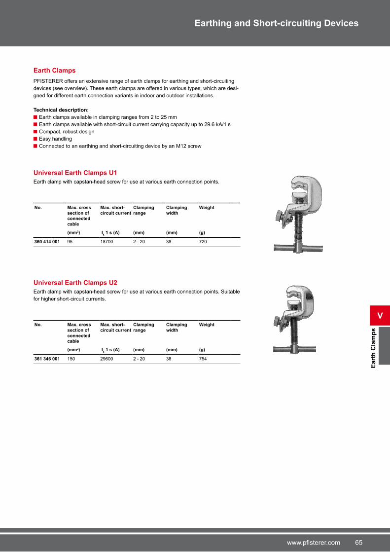
�5www.pfisterer.com
Ea
rth
Cla
mp
s
V
Earthing and Short-circuiting Devices
Earth Clamps
PFISTERER offers an extensive range of earth clamps for earthing and short-circuiting
devices (see overview). These earth clamps are offered in various types, which are desi-
gned for different earth connection variants in indoor and outdoor installations.
Technical description:
Earth clamps available in clamping ranges from 2 to 25 mm
Earth clamps available with short-circuit current carrying capacity up to 29.� kA/1 s
Compact, robust design
Easy handling
Connected to an earthing and short-circuiting device by an M12 screw
Universal Earth Clamps U1
Earth clamp with capstan-head screw for use at various earth connection points.
No. Max. cross
section of connected cable
Max. short-
circuit current
Clamping
range
Clamping
width
Weight
(mm2) Ik 1 s (A) (mm) (mm) (g)
360 414 001 95 18�00 2 - 20 38 �20
Universal Earth Clamps U2
Earth clamp with capstan-head screw for use at various earth connection points. Suitable
for higher short-circuit currents.
No. Max. cross section of connected cable
Max. short-circuit current
Clamping range
Clamping width
Weight
(mm2) Ik 1 s (A) (mm) (mm) (g)
361 346 001 150 29�00 2 - 20 38 �54

�� www.pfisterer.com
V
Ea
rth
Cla
mp
s
Earthing and Short-circuiting Devices
Universal Earth Clamps U3
Earth clamp with handle for use at various earth connection points.
No. Max. cross
section of
connected
cable
Max. short-
circuit current
Clamping
range
Clamping
width
Weight
(mm2) Ik 1 s (A) (mm) (mm) (g)
364 704 004 95 18�00 2 - 20 38 80�
Universal Earth Clamps U4
Earth clamp with capstan-head screw for use at various earth connection points.
No. Max. cross section of connected cable
Max. short-circuit current
Clamping range
Clamping width
Weight
(mm2) Ik 1 s (A) (mm) (mm) (g)
364 704 003 150 29�00 2 - 20 38 83�
Universal Earth Clamps U5
Earth clamp with handle for use at various earth connection points.
No. Max. cross section of connected cable
Max. short-cir-cuit current
Clamping range
Clamping width
Weight
(mm2) Ik 1 s (A) (mm) (mm) (g)
364 714 002 120 23�00 2 - 25 38 902
Earth Connection Sockets A1
Earth connection socket with wing screw for connection to a cylindrical earthing bolt.
No. Max. cross
section of connected
cable
Max. short-
circuit current
Clamping
range
Weight
(mm2) Ik 1 s (A) (mm) (g)
364 811 001 150 29�00 1� �5�

��www.pfisterer.com
Ea
rth
Cla
mp
s
V
Earthing and Short-circuiting Devices
Earth Connection Sockets A2
Earth connection socket with capstan-head screw for connection to a cylindrical earthing
bolt.
No. Max. cross
section of
connected
cable
Max. short-
circuit current
Clamping
range
Weight
(mm2) Ik 1 s (A) (mm) (g)
364 544 002 150 29�00 1� - 22 �3�
Earth Clamps E2
Earth clamp with capstan-head screw.
No. Max. cross section of connected cable
Max. short- circuit current
Clamping range
Weight
(mm2) Ik 1 s (A) (mm) (g)
360 419 004 �0 13800 2 - 30 3�0
Penetrating Earth Clamps F1
Earth clamp with capstan-head screw for use on coated masts. The cupped gripping
point and tip are hardened to ensure reliable contact.
No. Max. cross section of connected cable
Max. short- circuit current
Clamping range
Weight
(mm2) Ik 1 s (A) (mm) (g)
360 416 002 50 9900 2 - 20 442
Gösag Penetrating Earth Clamps F2
Earth clamp with capstan-head screw for use on coated masts. The cupped gripping
point and tip are hardened to ensure reliable contact.
No. Max. cross
section of
connected cable
Max. short-
circuit current
Clamping
range
Weight
(mm2) Ik 1 s (A) (mm) (g)
360 628 002 95 18�00 2 - 22 9�8
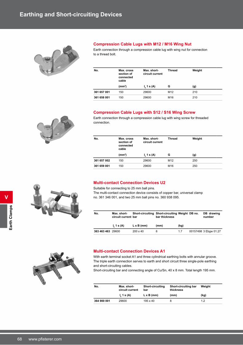
�8 www.pfisterer.com
V
Ea
rth
Cla
mp
s
Earthing and Short-circuiting Devices
Compression Cable Lugs with M12 / M16 Wing Nut
Earth connection through a compression cable lug with wing nut for connection
to a thread bolt.
No. Max. cross
section of
connected
cable
Max. short-
circuit current
Thread Weight
(mm2) Ik 1 s (A) G (g)
361 657 001 150 29�00 M12 210
361 658 001 150 29�00 M1� 210
Compression Cable Lugs with S12 / S16 Wing Screw
Earth connection through a compression cable lug with wing screw for threaded
connection.
No. Max. cross section of connected cable
Max. short- circuit current
Thread Weight
(mm2) Ik 1 s (A) G (g)
361 657 002 150 29�00 M12 250
361 659 001 150 29�00 M1� 250
Multi-contact Connection Devices U2
Suitable for connecting to 25 mm ball pins.
The multi-contact connection device consists of copper bar, universal clamp
no. 3�1 34� 001, and two 25 mm ball pins no. 3�0 938 095.
No. Max. short-
circuit current
Short-circuiting
bar
Short-circuiting
bar thickness
Weight DB no. DB drawing
number
Ik 1 s (A) L x B (mm) (mm) (kg)
363 463 463 29�00 200 x 40 � 1.� 0015�498 3 Ebgw 01.2�
Multi-contact Connection Devices A1
With earth terminal socket A1 and three cylindrical earthing bolts with annular groove.
The triple earth connection serves to earth and short circuit three single-pole earthing
and short-circuiting cables.
Short-circuiting bar and connecting angle of Cu/Sn, 40 x 8 mm. Total length 195 mm.
No. Max. short-
circuit current
Short-circuiting
bar
Short-circuiting bar
thickness
Weight
Ik 1 s (A) L x B (mm) (mm) (kg)
364 900 001 29�00 195 x 40 8 1.2

�9www.pfisterer.com
Ea
rth
Cla
mp
s
V
Earthing and Short-circuiting Devices
Multi-contact Connection Devices A2
With earth terminal socket A2 and three cylindrical earthing bolts with annular groove.
The triple earth connection serves to earth and short circuit three single-pole earthing
and short-circuiting cables.
Short-circuiting bar and connecting angle of Cu/Sn, 40 x 8 mm. Total length 195 mm.
No. Max. short-
circuit current
Short-circuiting
bar
Short-circuiting
bar thickness
Weight
Ik 1 s (A) L x B (mm) (mm) (kg)
364 899 001 29�00 195 x 40 8 1.3

�0 www.pfisterer.com
V
Ra
il E
art
h C
lam
ps
Earthing and Short-circuiting Devices
Rail Earthing Clamps
PFISTERER offers a range of rail earthing clamps for railway lines.
Rail Earth Clamps R50
This rail earth clamp is suitable for all rail base gauges. The small overall height (35 mm
below the rail base) means there is no need to remove gravel. A separate handle allows
easy placing of the clamp and protects the earth wire connection. When tightening the
clamp, the annular cutting edge cuts through layers of dirt and oxide, thus ensuring a
reliable contact. The counter surface is a hardened metal tip, which is spring-mounted
and insulated. The clamp is therefore flame-resistant in the event of a short circuit.
No. Max. cross section of connected cable
Max. short-circuit current
With ratchet Weight DB no. DB drawing number
(mm2) Ik 0,12 s (A) (g)
363 322 005 50 40000 ■ 2128 0015�500 3 Ebgw
01.13
363 322 006 50 40000 - 1�0� - -
Rail Earth Clamps R51
This rail earth clamp is designed as an earthing magnet for use on trolley lines.
No. Max. cross section of
connected cable
Max. short-circuit
current
Weight
(mm2) Ik 1 s (A) (g)
364 901 001 �0 13800 5000
Rail Earth Clamps R52
Suitable for grooved rails.
No. Max. cross section of
connected cable
Max. short- circuit current
Weight
(mm2) Ik 0,12 s (A) (g)
364 868 001 50 40000 858
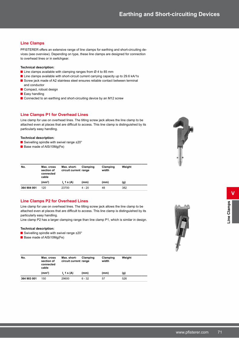
�1www.pfisterer.com
Lin
e C
lam
ps
V
Earthing and Short-circuiting Devices
Line Clamps
PFISTERER offers an extensive range of line clamps for earthing and short-circuiting de-
vices (see overview). Depending on type, these line clamps are designed for connection
to overhead lines or in switchgear.
Technical description:
Line clamps available with clamping ranges from Ø 4 to 85 mm
Line clamps available with short-circuit current carrying capacity up to 29.� kA/1s
Screw jack made of A2 stainless steel ensures reliable contact between terminal
and conductor
Compact, robust design
Easy handling
Connected to an earthing and short-circuiting device by an M12 screw
Line Clamps P1 for Overhead Lines
Line clamp for use on overhead lines. The tilting screw jack allows the line clamp to be
attached even at places that are difficult to access. This line clamp is distinguished by its particularly easy handling.
Technical description:
Swivelling spindle with swivel range ±20°
Base made of AlSi10Mg(Fe)
No. Max. cross section of connected cable
Max. short-circuit current
Clamping range
Clamping width
Weight
(mm2) Ik 1 s (A) (mm) (mm) (g)
364 904 001 120 23�00 4 - 20 48 382
Line Clamps P2 for Overhead Lines
Line clamp for use on overhead lines. The tilting screw jack allows the line clamp to be
attached even at places that are difficult to access. This line clamp is distinguished by its particularly easy handling.
Line clamp P2 has a larger clamping range than line clamp P1, which is similar in design.
Technical description:
Swivelling spindle with swivel range ±20°
Base made of AlSi10Mg(Fe)
No. Max. cross
section of
connected cable
Max. short-
circuit current
Clamping
range
Clamping
width
Weight
(mm2) Ik 1 s (A) (mm) (mm) (g)
364 903 001 150 29�00 � - 32 5� 52�
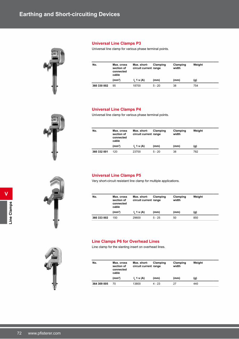
�2 www.pfisterer.com
V
Lin
e C
lam
ps
Earthing and Short-circuiting Devices
Universal Line Clamps P3
Universal line clamp for various phase terminal points.
No. Max. cross
section of
connected
cable
Max. short-
circuit current
Clamping
range
Clamping
width
Weight
(mm2) Ik 1 s (A) (mm) (mm) (g)
360 330 002 95 18�00 5 - 20 38 �54
Universal Line Clamps P4
Universal line clamp for various phase terminal points.
No. Max. cross section of connected cable
Max. short-circuit current
Clamping range
Clamping width
Weight
(mm2) Ik 1 s (A) (mm) (mm) (g)
360 332 001 120 23�00 5 - 20 38 �82
Universal Line Clamps P5
Very short-circuit resistant line clamp for multiple applications.
No. Max. cross section of connected cable
Max. short-circuit current
Clamping range
Clamping width
Weight
(mm2) Ik 1 s (A) (mm) (mm) (g)
360 333 002 150 29�00 5 - 25 50 850
Line Clamps P6 for Overhead Lines
Line clamp for the slanting insert on overhead lines.
No. Max. cross
section of connected
cable
Max. short-
circuit current
Clamping
range
Clamping
width
Weight
(mm2) Ik 1 s (A) (mm) (mm) (g)
364 309 005 �0 13800 4 - 23 2� 440

�3www.pfisterer.com
Lin
e C
lam
ps
V
Earthing and Short-circuiting Devices
Line Clamps P7 for High-Voltage Overhead Lines
Line clamp for the slanting insert on high-voltage overhead lines.
No. Max. cross
section of
connected
cable
Max. short-
circuit current
Clamping
range
Clamping
width
Weight
(mm2) Ik 1 s (A) (mm) (mm) (g)
363 245 006 120 23�00 4,5 - 35 34 �14
High-Voltage Line Clamps P8
Line clamp for connection to Al and Al/St lines, tubes and line contacts.
No. Max. cross section of connected cable
Max. short-circuit current
Clamping range
Clamping width
Weight
(mm2) Ik 1 s (A) (mm) (mm) (g)
364 459 009 150 29�00 10 - 85 40 88�
Parallel Line Clamps P9
Line clamp for the slanting insert on high-voltage overhead lines. Due to the parallel
setting of the clamping jaws, this line clamp is suitable for attaching at high positions, e.g.
the cross arms of high-voltage poles.
No. Max. cross
section of
connected cable
Max. short-
circuit current
Clamping
range
Clamping
width
Weight
(mm2) Ik 1 s (A) (mm) (mm) (g)
360 335 003 95 18�00 10 - 32 38 9�8
Parallel Line Clamps P10
Line clamp for the slanting insert on high-voltage overhead lines. Due to the parallel
setting of the clamping jaws, this line clamp is suitable for attaching at high positions, e.g.
the cross arms of high-voltage poles.
No. Max. cross
section of connected
cable
Max. short-
circuit current
Clamping
range
Clamping
width
Weight
(mm2) Ik 1 s (A) (mm) (mm) (g)
360 329 001 50 9900 5 - 1� 40 �22

�4 www.pfisterer.com
V
Lin
e C
lam
ps
Earthing and Short-circuiting Devices
Parallel Line Clamps P11
Line clamp for the slanting insert on high-voltage overhead lines. Due to the parallel
setting of the clamping jaws, this line clamp is suitable for attaching at high positions, e.g.
the cross arms of high-voltage poles.
This line clamp is also fitted with a guard stirrup. This can be used to prevent loosened line clamps from falling off.
No. Max. cross
section of
connected
cable
Max. short-
circuit current
Clamping
range
Clamping
width
Weight
(mm2) Ik 1 s (A) (mm) (mm) (g)
360 335 004 95 18�00 10 - 32 38 1010
Line Clamps P12 for Blade Contacts
Line clamp for use in all-insulated switchgear in retraction system Type R with blade
contact of thickness 10, 1� and 20 mm and bead. The clamping jaws on the line clamp
have fine-toothed grooves to ensure secure electrical contact and the best possible mechanical grip.
No. Max. cross section of connected cable
Max. short-circuit current
Clamping range
Clamping width
Weight
(mm2) Ik 1 s (A) (mm) (mm) (g)
363 091 297 150 29�00 10 - 25 40 914
Current Collector Clamps S100
Technical description:
With tilting spindle
For current sampling on overhead lines up to 300 mm2
Screw jack with cross-pin for insulating pole 3�3 810 8xx
Compact, simple robust design
Spindle max. tightening torque = 25 Nm
Conductor max. tightening torque = � Nm
No. Swivel range Conductor range
Continous current-carrying
capacity
Max. cross section of
connected cable
Weight
(mm) (A) (mm2) (g)
360 328 010 ± 20° 4 - 20 144 25 3�0

�5www.pfisterer.com
Co
nta
ct
Wir
e E
art
h C
lam
ps
V
Earthing and Short-circuiting Devices
Contact Wire Earth Clamps
PFISTERER offers contact wire earth clamps for railway grounding devices. These
contact wire earth clamps are designed for connection to various contact wires.
Technical description:
Contact wire earth clamps for grooved, circular, sectional contact wires and double
contact wires
Jack screw made of A2 stainless steel ensures reliable contact between clamp and
contact wire
Compact, robust design
Easy handling
Earthing poles available for attaching all types of contact wire earth clamps
Contact Wire Earth Clamps P50
This contact wire earth clamp has a torsion-free earthing cable terminal at the front.
The bow and thrust block are finely grooved to ensure secure electric contact and firm mechanical grip even when the conductors are corroded.
Technical description:
Conductor range 4.5 – 35 mm
With feeler bow for verifying absence of voltage to railway-internal specifications
No. Max. cross section of connected cable
Max. short-circuit current
Clamping range
Clamping width
Weight DB no. DB drawing number
(mm2) Ik 1 s (A) (mm) (mm) (g)
363 418 003 120 23�00 4,5 - 35 34 814 0015�499 4 Ebgw 01.2�
Contact Wire Earth Clamps P51
This contact wire earth clamp is fitted with a flexible spindle and is used for grooved, circular or profile wires.
Technical description:
With feeler bow for easy insertion into the contact wire
The spring-mounted thrust block is connected to the M12 connecting screw on
the back by means of flexible copper tapes 3�1 499 002 with shortened sensor
No. Max.
cross section of
connected cable
Max.
short-circuit current
Contact wire
Clamping width
Weight DB no. DB drawing number
(mm2) Ik 0,12 s
(A)(mm) (g)
361 499 001 50 3�500 Ri 80 - 150 30 10�0 0015�4�1 3 Ebgw 01.14
361 499 002 50 3�500 Ri 80 - 150 30 1010 - -
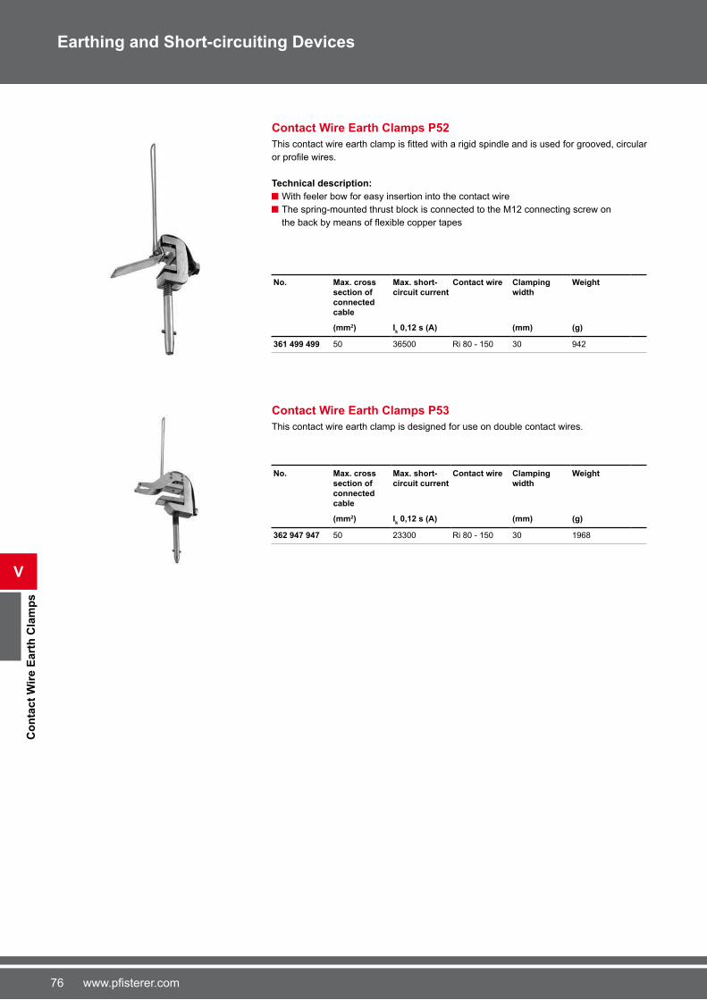
�� www.pfisterer.com
V
Co
nta
ct
Wir
e E
art
h C
lam
ps
Earthing and Short-circuiting Devices
Contact Wire Earth Clamps P52
This contact wire earth clamp is fitted with a rigid spindle and is used for grooved, circular or profile wires.
Technical description:
With feeler bow for easy insertion into the contact wire
The spring-mounted thrust block is connected to the M12 connecting screw on
the back by means of flexible copper tapes
No. Max. cross
section of
connected
cable
Max. short-
circuit current
Contact wire Clamping
width
Weight
(mm2) Ik 0,12 s (A) (mm) (g)
361 499 499 50 3�500 Ri 80 - 150 30 942
Contact Wire Earth Clamps P53
This contact wire earth clamp is designed for use on double contact wires.
No. Max. cross section of connected cable
Max. short-circuit current
Contact wire Clamping width
Weight
(mm2) Ik 0,12 s (A) (mm) (g)
362 947 947 50 23300 Ri 80 - 150 30 19�8

��www.pfisterer.com
Eart
hin
g a
nd
Ph
as
e F
ixe
d P
oin
ts
V
Earthing and Short-circuiting Devices
Earthing and Phase Fixed Points
PFISTERER provides a range of both earthing and phase fixed points.Special phase fixed points on request.
Maximum installation torque
M10: 33 Nm
M12: 5� Nm
M1�: 135 Nm
Ball Pin, Straight, with Outside Thread
According to DIN 48088 Part 1.
Technical description:
Railway authorities licence 4 Ebgw 01.24
3�0 938 095 DB-No. 00 15� 503
3�0 938 939 DB-No. 00 15� 495
3�0 384 003 DB-No. 00 �21 849
No. Max. cross section of connected cable
Head diameter Thread length Thread Width across flats
Max. short- circuit current
for line clamp
(mm2) (mm) (mm) G (SW) Ik 1 s (A)
360 382 004 95 20 28 M12 22 18�00 3�0 330 002
360 382 005 95 20 38 M12 22 18�00 3�0 330 002
360 382 006 95 20 48 M12 22 18�00 3�0 330 002
360 938 095 120 25 25 M1� 2� 23�00 3�0 332 001
3�0 333 002
360 384 002 120 25 28 M12 2� 23�00 3�0 332 001
3�0 333 002
360 384 003 120 25 38 M12 2� 23�00 3�0 332 001
3�0 333 002
360 384 004 120 25 48 M12 2� 23�00 3�0 332 001
3�0 333 002
360 938 939 120 25 55 M1� 2� 23�00 3�0 332 001
3�0 333 002

�8 www.pfisterer.com
V
Eart
hin
g a
nd
Ph
as
e F
ixe
d P
oin
ts
Earthing and Short-circuiting Devices
Ball Pin, Straight, with Inside Thread
According to DIN 48088 Part 1.
No. Max. cross
section of
connected
Head diameter Thread Width across flats Max. short-circuit
current
for line clamp
(mm2) (mm) G (SW) Ik 1 s (A)
612 633 005 95 20 M10 22 18�00 3�0 330 002
612 633 004 95 20 M12 22 18�00 3�0 330 002
615 820 001 120 25 M12 2� 23�00 3�0 332 001
3�0 333 002
615 822 001 120 25 M1� 2� 23�00 3�0 332 001
3�0 333 002
360 786 003 �0 20 M1� 24 13800 3�0 330 002
Ball Pin, Angled, with Outside Thread
No. Bracket Max. cross section of connected
cable
Head diameter Thread length Thread Width across flats
Max. short- circuit current
for line clamp
(mm2) (mm) (mm) G (SW) Ik 1 s (A)
360 784 001 45° 95 20 38 M12 24 18�00 3�0 330 002
360 385 001 90° 120 25 45 M12 2� 23�00 3�0 332 001
3�0 333 002
360 786 001 90° �0 20 �5 M12 24 13800 3�0 330 002

�9www.pfisterer.com
Eart
hin
g a
nd
Ph
as
e F
ixe
d P
oin
ts
V
Ball Pin, Angled, with Inside Thread
No. Bracket Max. cross
section of connected cable
Head diameter Thread Width across
flats
Max. short-
circuit current
for line clamp
(mm2) (mm) G (SW) Ik 1 s (A)
360 385 002 45° 120 25 M12 2� 23�00 3�0 332 001
3�0 333 002
360 786 002 90° �0 20 M12 24 13800 3�0 330 002
611 370 001 45° 120 20 M12 24 23�00 3�0 330 002
T-Bolts, Straight, with Outside Thread
suitable for universal line clamp P3.
No. Max. cross section of connected cable
Diameter Width Thread length Thread Max. short-circuit current
(mm2) Ø (mm) (mm) (mm) G Ik 1 s (A)
360 372 001 95 15 30 28 M12 18�00
360 372 002 95 15 30 48 M12 18�00
T-Bolts, Straight, with Inside Thread
suitable for universal line clamp P3.
No. Max. cross section
of connected cable
Diameter Width Thread Max. short-circuit
current
(mm2) Ø (mm) (mm) G Ik 1 s (A)
610 670 001 95 20 58 M12 18�00
615 805 001 95 15 30 M12 18�00
Earthing and Short-circuiting Devices
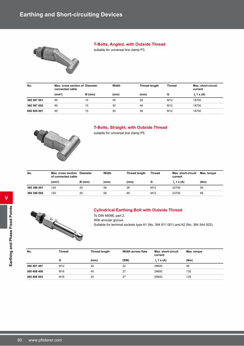
80 www.pfisterer.com
V
Eart
hin
g a
nd
Ph
as
e F
ixe
d P
oin
ts
T-Bolts, Angled, with Outside Thread
suitable for universal line clamp P3.
No. Max. cross section of
connected cable
Diameter Width Thread length Thread Max. short-circuit
current
(mm2) Ø (mm) (mm) (mm) G Ik 1 s (A)
360 567 001 95 15 30 28 M12 18�00
360 567 002 95 15 30 48 M12 18�00
600 925 001 95 15 30 38 M12 18�00
T-Bolts, Straight, with Outside Thread
suitable for universal line clamp P5.
No. Max. cross section of connected cable
Diameter Width Thread length Thread Max. short-circuit current
Max. torque
(mm2) Ø (mm) (mm) (mm) G Ik 1 s (A) (Nm)
360 386 001 120 20 58 28 M12 23�00 5�
360 386 002 120 20 58 48 M12 23�00 5�
Cylindrical Earthing Bolt with Outside Thread
To DIN 48088, part 2.
With annular groove.
Suitable for terminal sockets type A1 (No. 3�4 811 001) and A2 (No. 3�4 544 002).
No. Thread Thread length Width across flats Max. short-circuit current
Max. torque
G (mm) (SW) Ik 1 s (A) (Nm)
360 407 407 M12 40 22 29�00 5�
360 408 408 M1� 40 2� 29�00 135
360 408 003 M1� 25 2� 29�00 135
Earthing and Short-circuiting Devices
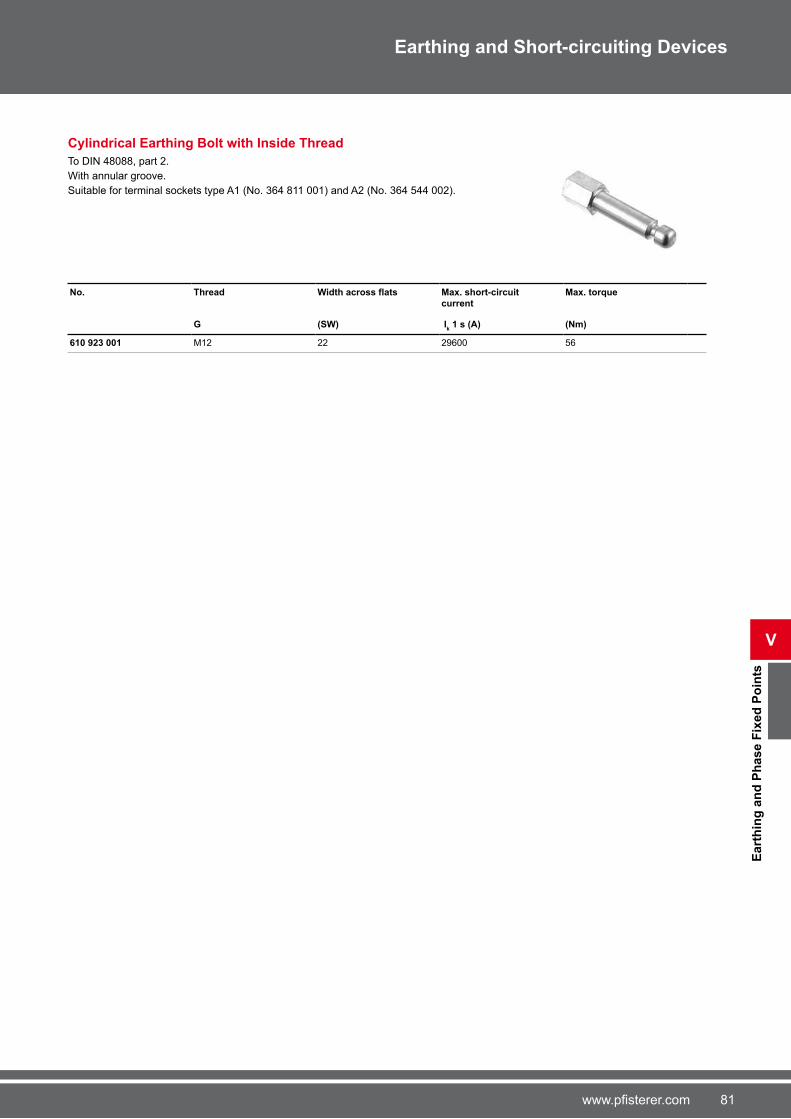
81www.pfisterer.com
Eart
hin
g a
nd
Ph
as
e F
ixe
d P
oin
ts
V
Earthing and Short-circuiting Devices
Cylindrical Earthing Bolt with Inside Thread
To DIN 48088, part 2.
With annular groove.
Suitable for terminal sockets type A1 (No. 3�4 811 001) and A2 (No. 3�4 544 002).
No. Thread Width across flats Max. short-circuit
current
Max. torque
G (SW) Ik 1 s (A) (Nm)
610 923 001 M12 22 29�00 5�
82 www.pfisterer.com
Vo
ltag
e D
ete
cti
ng
Syste
ms
VI
Voltage Detecting Systems
Voltage detecting systems that meet Standard EN �1243-5:2001 are used for ensuring
absence of voltage in metal-enclosed switchgear and transformers. As the live compo-
nents in these systems cannot be contacted with voltage detectors, it is necessary to use
voltage detecting systems that can clearly identify and indicate a capacitively coupled
out signal as an operating voltage. This signal is coupled out by the integrated coupling
electrodes that may be integrated in various components:
Post-type insulator with capacitive voltage divider
Transducer
Bushings
Duresca rails
Outside/inside cone cable terminations
Voltage detection systems used for both medium and high voltages.
Standard EN 61243-5:2001 generally distinguishes between two systems, which define the interface conditions for the reliable operation of voltage detecting systems:
HR systems (high resistance system)
LRM systems (low resistance systems)
PFISTERER supplies the following components for both systems:
Voltage detecting systems
Connection materials such as connecting cables and connector strips
Testing systems for testing voltage detecting systems
Testing systems for testing interfaces
Phase comparators
Our voltage detection systems are optimised for PFISTERER CONNEX connection
technology components.
Voltage Detecting Systems

83www.pfisterer.com
VIIn
dic
ato
rs
Voltage Detecting Systems
Indicators
These indicators show when operating voltage is present.
Continuous Voltage Indicator DSA-2
The DSA-2 continuous voltage indicator is a plug-in indicator for the HR system.
It allows capacitively coupled out voltages to be checked for absence of voltage.
Technical description:
No external power required
Voltage indicator with flashing red LED All-insulated system (IP��) made of impact-resistant plastic with cast-on
CEE plug connector
Functioning test possible on the 230 V AC plug socket
EURO-Test HR in-service test possible
Suitable for all climatic zones
No.
827 161 005
Continuous Voltage Indicator DSA-LRM
The DSA-LRM continuous voltage indicator is a plug-in indicator for the LRM system.
It allows capacitively coupled out voltages to be checked for absence of voltage.
Technical description:
No external power required
Voltage indication by flashing red LED All-insulated system (IP��) made of impact-resistant plastic
Integrated connector pins with seal for interface
In-service test possible with Euro-Test LRM
Suitable for all climate zones
No.
827 020 001

84 www.pfisterer.com
Ind
icato
rs
VI
Voltage Detecting Systems
Integrated Voltage Detecting System DSA-i3
The DSA-i3 integrated voltage detecting system has an integrated indicator. It is desired
for use in switchgear. An additional display removes the need for in-service tests. This
voltage detecting system is therefore particularly maintenance-free, reliable and cost-
effective when used in continuous operation.
Technical description:
No external power supply required
Red LCD display
Test sockets available for phase comparison
Additional third socket for testing the integrated LCD display
Secure cover for sockets
Sensible test process using three feeler pins
Integrated breaking point for voltage-limiting
Simple assembly
No in-service test required
No. Nominal frequency
Threshold voltage
Type of protection
Input impedance
Operation temperature
width x height x depth
fN (Hz) (V) (MΩ) (°C) (mm)
827 216 003 50...�0 4...5 V IP �� 2 -25 ... +55 9� x 48 x 30
Additional Capacity for DSA-i3 Voltage Detecting System
Additional capacitances are available for adapting the DSA-i3 integrated voltage detec-
tion system to the interface; these can be plugged into the side of the voltage detection
system.
No. Version Circuit board Additional capacity
(pF)
827 216 003 2 980 02� 001 4�0 pF
827 216 003 3 980 02� 002 2200 pF
827 216 003 4 980 02� 003 3300 pF
827 216 003 5 980 02� 004 10000 pF
Assembly Bracket
This practical assembly bracket is available for mounting the DSA-i3 integrated voltage
detection system outside front panels.
No.
993 008 002

85www.pfisterer.com
VIIn
terf
aces a
nd
Co
nn
ecti
ng
Lead
s
Voltage Detecting Systems
Interfaces and Connecting Leads
PFISTERER offers a range of interfaces and connecting leads for connecting indicators.
Connecting leads on request.
Three-pole Interfaces for HR-System
This three-pole interface for HR systems is designed as a measuring and testing block
with safety socket and earth socket. It can be mounted on switchgear.
Note:
To meet the standard, this interface must also be equipped with a rated breaking point
for voltage limiting. The interface, the terminals on the coupling element, and the rated
breaking point must be protected against humidity.
No.
560 915 001
Single-pole Interface for HR-System
This single-pole interface for HR system is designed as a test socket. It can be moun-
ted anywhere near the capacitive tap.
Note:
The standard requires that this interface is also to be equipped with a rated breaking
point for voltage limiting. The interface, the terminals on the coupling element, and the
rated breaking point must be protected against humidity.
No.
827 668 001
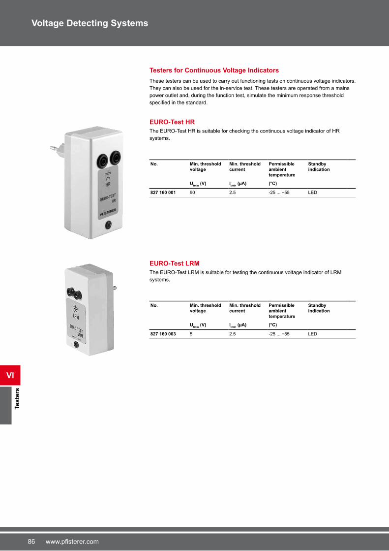
8� www.pfisterer.com
Teste
rs
VI
Voltage Detecting Systems
Testers for Continuous Voltage Indicators
These testers can be used to carry out functioning tests on continuous voltage indicators.
They can also be used for the in-service test. These testers are operated from a mains
power outlet and, during the function test, simulate the minimum response threshold
specified in the standard.
EURO-Test HR
The EURO-Test HR is suitable for checking the continuous voltage indicator of HR
systems.
No. Min. threshold
voltage
Min. threshold
current
Permissible
ambient
temperature
Standby
indication
Utmin
(V) Itmin
(µA) (°C)
827 160 001 90 2.5 -25 ... +55 LED
EURO-Test LRM
The EURO-Test LRM is suitable for testing the continuous voltage indicator of LRM
systems.
No. Min. threshold voltage
Min. threshold current
Permissible ambient temperature
Standby indication
Utmin
(V) Itmin
(µA) (°C)
827 160 003 5 2.5 -25 ... +55 LED

8�www.pfisterer.com
VITeste
rs
Voltage Detecting Systems
Testers for Interfaces
These testers can be used for testing the interface.
MP-Test
This MP tester is suitable for testing the interfaces on HR systems and LRM systems. It
can be used in connection with a multimeter.
No.
827 094 001
Testers for Continuous Voltage Indicators and Interfaces
PFISTERER offers testers for continuous voltage indicators and interfaces in one set.
Test Box
This text box contains testers for continuous voltage indicators and interfaces, and for the
HR and LRM systems.
Technical description:
■ Practical storage case with foam lining■ Multimeter■ MP test■ HR EURO test■ LRM EURO test
No.
827 092 002

88 www.pfisterer.com
Teste
rs
VI
Voltage Detecting Systems
Phase Comparators for Interfaces and Measuring Points
Phase comparators that meet standard EN �1243-5:2001 can be used to carry out phase
comparisons on interfaces and measuring points.
Electronic Phase Comparators EPV
The EPV universal phase comparator allows phase comparison on interfaces and
measuring points. It can be used for the HR system as well as the LRM system. It also
allows checks for absence of voltage and tests on the interface.
Technical description:
Integrated test leads
Touchproof testing
Function test and battery check with integrated self-test
Integrated voltage indication
Active phase balance indication by two LEDs
(green=phase balance; red=phase unbalance)
Interface control
No. Scope of application
With 2 HR adapters
Nominal frequency
Weight width x height x depth Dimensions of carrying case (length/width/ height)
fN (Hz) (g) (mm) (mm)
827 189 007 LRM system HR system 50...�0 220 100 x 200 x 45 300 x 110 x �0
In-service Tests for Phase Comparators EPV
We provide in-service tests for the EPV phase comparator.
PFISTERER have been successfully carrying out these in-service tests on their own test
equipment for many years. And this is how the EPV phase comparator is tested.
When the tests are completed, the results are documented in detail.
To request an In-service test, please contact your local sales agency.
For customers in Germany please use the following mailing address:
PFISTERER Kontaktsysteme GmbH & Co. KG
Bereich Wiederholungsprüfung
Bahnhofstraße 30
8954� Gerstetten - Gussenstadt
Germany
No. Description
200 000 018 EPV

89www.pfisterer.com
VII
Acces
so
ries
Accessories
Adapter for Voltage Detectors
All KP-Test 5 Series single-pole voltage detectors are available either complete (with in-
sulating poles) or separately (without insulating poles). With the separate type, the opera-
tor uses his own insulating poles. In this case, the minimum insulation requirements and
minimum insulation lengths must be maintained.
PFISTERER offers a range of adapters for attaching separate KP-Test 5 voltage detec-
tors to various connection variants.
Adapter, C1 Series
Adapter from PFISTERER hexagon to various other systems.
No. Version Description
935 100 001 C1A Universal toothed coupling with
groove
935 100 002 C1B Spindle
935 100 003 C1C Hexagon SW 12
935 100 004 C1D „England“ version
935 100 005 C1E Universal toothed coupling with
M8 thread
Adapter, C2 Series
Adapter from universal adapter to various other systems. Can be used for KP-Test 5HL.
Adapters can be supplied on request.
No. Version
935 101 002 C2B
935 101 003 C2C
935 101 004 C2D
935 101 005 C2F

90 www.pfisterer.com
Acces
so
ries
VII
Accessories
Test Electrode Attachments for KP-Test 5
Angled Types, 90°
Can be used for all KP-Test 5 Series devices. For indoor installations only.
No. Nominal voltage
Un (kV)
935 000 001 3 - 3�
Types for Medium Voltage Overhead Lines
Can be used for all KP-Test 5 Series devices. For use on medium voltage overhead
lines.
No.
935 000 002
Types for Special Switchgear, Type I
Can be used for all KP-Test 5 Series devices. For use on various Eaton, Holec and Ma-
gnefix switchgear. For indoor installations only.
No. Nominal voltage
Un (kV)
935 000 003 3 - 15
Types for Special Switchgear, Type II
Can be used for all KP-Test 5 Series devices. For use on various Calor Emag, Isopond
and Krone/KES switchgear with 11 mm diameter. For indoor installations only.
No. Nominal voltage
Un (kV)
935 000 004 3 - 24
Types for Special Switchgear, Type III
Can be used for all KP-Test 5 Series devices. For use on medium voltage switchgear
with 5.5 mm diameter. For indoor installations only.
No. Nominal voltage
Un (kV)
935 000 005 1 - 10

91www.pfisterer.com
VII
Acces
so
ries
Accessories
Headpieces for Operating Poles
Switching Heads
all-insulated with actuating bolt
No. Material
614 495 495 POM nf
Carrying case
Carrying Case for Voltage Detectors KP-Test 5
For safe transport and dust-free storage, PFISTERER supplies a high-quality carrying
case for the KP-Test 5 voltage detector.
Technical description:
Hard-shell case made of impact-resistant plastic
Aluminium strips for edge protection
Foam lining for KP-Test 5 voltage detector and related accessories
No. Insertion depth of voltage detector
Width Height Depth
Ai (mm) (mm) (mm) (mm)
900 073 006 220
393
�00 125 218
900 073 005 �03 920 125 21�
Carrying Case for Voltage Detectors KP-Test 5L
For safe transport and dust-free storage, PFISTERER supplies a handy carrying case
for the KP-Test 5L voltage detector.
Technical description:
Hard-shell case made of impact-resistant plastic
Bright red colour with marking
Foam lining for KP-Test 5L voltage detector and associated adapters
No. Width Height Depth
(mm) (mm) (mm)
900 075 001 444 320 108

92 www.pfisterer.com
Acces
so
ries
VII
Accessories
Carrying Case for Single-pole Phase Comparators
Used for the safe transport and dust-free storage of phase comparators SPPC.
Technical description:
Hard-shell case made of impact-resistant plastic
Aluminium strips for edge protection
Foam lining for phase comparator and accessories
No. Width Height Depth Suitable for
(mm) (mm) (mm)
900 068 001 �05 80 240 3�4�88004
900 073 001 1020 80 250 3�4�88002
3�4�88003
3�4825002
3�4825003
3�4825004
3�4�50001
3�4830001
900 073 002 900 190 250 3�4�88001
3�4825001
900 073 003 888 143 235 3�4�88001
3�4825001
900 073 004 1050 1�0 220 3�4�88002
3�4�88003
3�4825002
3�4825003

93www.pfisterer.com
VII
Acces
so
ries
Accessories
Carrying Case
Carrying Case for Voltage Detectors KP-Test 5
used for the safe transport and dust-free storage of KP-Test 5 voltage detectors.
Technical description:
Storage case made of hard-wearing artificial leather Easy to close, using the Velcro fastener
Flexibly adjustable carrying straps
No. Insertion depth of voltage detector
Width Height Suitable for
Ai (mm) (mm) (mm)
364 887 002 220
393
�30 2�0 930100003
930100005
930100010
930110005
930110010
930110013
930110020
364 887 004 �03 1000 2�0 930120003
930120005
930120010
364 887 003 910 1240 2�0 930140010
930140020
Carrying Case for Single-pole Phase Comparators
used for the safe transport and dust-free storage of phase comparators SPPC.
Technical description:
Storage case made of hard-wearing artificial leather Easy to close, using the Velcro fastener
Flexibly adjustable carrying straps
No. Width Height Suitable for
(mm) (mm)
364 886 001 1050 410 3�4�88001
3�4�88002
3�4�88003
3�4825001
3�4825002
3�4825003
3�4825004
364 887 001 �00 2�0 3�4�88004
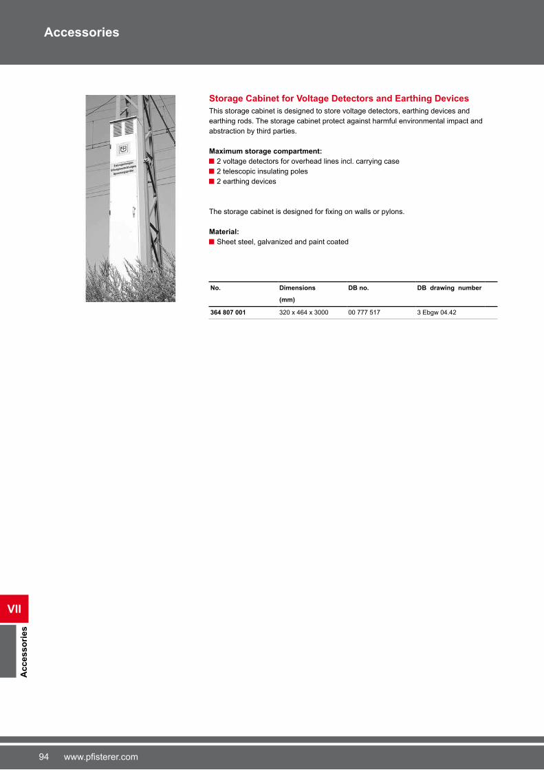
94 www.pfisterer.com
Acces
so
ries
VII
Accessories
Storage Cabinet for Voltage Detectors and Earthing Devices
This storage cabinet is designed to store voltage detectors, earthing devices and
earthing rods. The storage cabinet protect against harmful environmental impact and
abstraction by third parties.
Maximum storage compartment:
2 voltage detectors for overhead lines incl. carrying case
2 telescopic insulating poles
2 earthing devices
The storage cabinet is designed for fixing on walls or pylons.
Material:
Sheet steel, galvanized and paint coated
No. Dimensions DB no. DB drawing number
(mm)
364 807 001 320 x 4�4 x 3000 00 ��� 51� 3 Ebgw 04.42

95www.pfisterer.com
VII
Acces
so
ries
Accessories
Wall Holders
Flexible Wall Holders
Wall holder for space-saving storage and for holding KP-Test 5, one-pole phase
comparators SPPC, operating and earthing poles.
Technical description:
Holder made of impact-resistant plastic
Clamping belt made of heavy-duty rubber
Easily mounted on the guide bar provided, or directly on the wall
No. for pole diameter
(mm)
360 330 100 20 - 30
360 330 101 30 - 40
Guide Bars for Wall Holders
No.
360 330 102
Double Wall Holders
For storing earthing and short-circuiting devices at stations. Bracket with 2 fixing clamps for operating and/or earthing poles.
No. Weight
(kg)
360 877 001 0.8
Wall Holders for Earthing and Short-circuiting Devices
For storing earthing and short-circuiting devices at stations.
No. Weight
(kg)
360 878 001 5.2

9� www.pfisterer.com
Acces
so
ries
VII
Accessories
Wall Holders for Fuses
For holding a set of HH fuses with fuse tongs For wall mounting, Ø 9 mm drill holes, hole
spacing 390 mm.
No. Weight
(kg)
364 007 001 1.�
Retaining Clips for Operating and Earthing Poles
For wall mounting.
Technical description:
For storing operating and earthing poles
Spring bronze, electro- tinned
Applicable for tube diameter 30 – 43mm
With two mounting holes, each diameter: 5,5mm
No. Material Surface Weight
(kg)
360 323 323 Spring bronze Electro-tinned 0.1

9�www.pfisterer.com
VII
Acces
so
ries
Accessories
Other Accessories
Silicone Compound „DC 4“
For maintenance of all operating poles that meet DIN VDE 0�81-1/10.8�, following the
related operating instructions.
No. Type Weight
(g)
002 922 922 tube 100
Earthing Spikes
Technical description:
T-iron earthing spike, hot-dip galvanized, (without earthing cable), with M12 connecting
screw and two half-shells for winding the extension earthing cable.
No. Length Weight
(mm) (kg)
360 115 115 1300 3.�
Suspension Hook
For profile-free suspension of earthing wire.
No. DB no. DB drawing number
360 453 453 0015�4�5 3 Ebgw 01.11
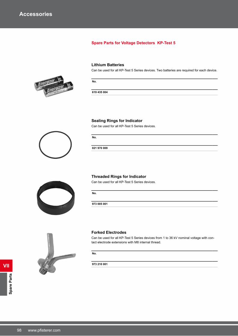
98 www.pfisterer.com
Sp
are
Part
s
VII
Accessories
Spare Parts for Voltage Detectors KP-Test 5
Lithium Batteries
Can be used for all KP-Test 5 Series devices. Two batteries are required for each device.
No.
619 435 004
Sealing Rings for Indicator
Can be used for all KP-Test 5 Series devices.
No.
021 970 009
Threaded Rings for Indicator
Can be used for all KP-Test 5 Series devices.
No.
973 005 001
Forked Electrodes
Can be used for all KP-Test 5 Series devices from 1 to 3� kV nominal voltage with con-
tact electrode extensions with M8 internal thread.
No.
973 210 001

99www.pfisterer.com
VII
Sp
are
Part
s
Accessories
Spare Parts for Earth Fittings
Connecting Clusters
Connecting cluster consisting of upper and lower parts, for use on multi-pole earthing
and short-circuiting devices. Compression cable lugs and heat-shrink tubes are not
included.
No. Connecting cluster
(mm2)
622 680 004 25 - 35
622 685 005 50 - �0
622 681 006 95 - 150

100 www.pfisterer.com
Company: Name:
Telephone: Date:
E-Mail: Signature:
1 Type: single-pole two-pole three-pole four-pole
3�9 201 001 3�9 100 001 3�9 203 001 3�9 100 003
2 Cables:
Conductor cable cross-section: mm2
Length of conductor cable: a: mm b: mm d: mm
Earth cable cross-section: mm2
Length of earth cable: c: mm
3 Clamps
Line clamp: Earth clamp:
Form for request for Earthing and Short-circuit devices
a b
c
a d
c
b a d
c
b a
c

101www.pfisterer.com
102 www.pfisterer.com
Nr. Seite
0002 922 922 9�
021 970 009 98
2200 000 001 31
200 000 002 31
200 000 003 31
200 000 004 31
200 000 005 31
200 000 006 31
200 000 012 35
200 000 014 31
200 000 016 35
200 000 017 35
200 000 018 88
200 000 200 31
3360 115 115 9�
360 323 323 9�
360 328 010 �4
360 329 001 �3, �3
360 330 002 �3, �2
360 330 100 95
360 330 101 95
360 330 102 95
360 332 001 �3, �2
360 333 002 �3, �2
360 335 003 �3, �3
360 335 004 �3, �4
360 372 001 �9
360 372 002 �9
360 382 004 ��
360 382 005 ��
360 382 006 ��
360 384 002 ��
360 384 003 ��
360 384 004 ��
360 385 001 �8
360 385 002 �9
360 386 001 80
360 386 002 80
360 407 407 80
360 408 003 80
360 408 408 80
360 414 001 �2, �5
360 416 002 �2, ��
360 419 004 �2, ��
360 453 453 9�
360 481 481 5�
360 488 000 39
360 491 001 40
360 491 002 40
360 528 528 5�
360 528 529 5�
360 528 530 5�
Nr. Seite
360 528 531 5�
360 567 001 80
360 567 002 80
360 628 002 �2, ��
360 784 001 �8
360 786 001 �8
360 786 002 �9
360 786 003 �8
360 877 001 95
360 878 001 95
360 938 095 ��
360 938 939 ��
361 346 001 �2, �5
361 499 ��
361 499 001 �4
361 499 499 �4, ��
361 657 001 �2, �8
361 657 002 �2, �8
361 658 001 �2, �8
361 659 001 �2, �8
362 000 001 39
362 744 4�
362 744 744 4�
362 745 002 4�
362 745 745 4�
362 808 808 3�
362 947 947 �4, ��
363 091 297 �3, �4
363 245 006 �3, �3
363 280 002 41
363 322 005 �4, �0
363 322 006 �0
363 418 003 �4, �5
363 463 463 �8
363 571 571 �0
363 625 001 22
363 625 004 22
363 625 005 22
363 800 000 58
363 810 810 3�
363 810 811 3�
363 810 812 3�
363 810 816 3�
363 815 818 3�
364 007 001 9�
364 035 004 38
364 035 005 38
364 035 008 38
364 035 035 38
364 035 036 38
364 035 037 38
364 035 042 38
364 035 043 38
364 084 001 43
364 084 002 43
364 084 084 43
364 084 086 43
Nr. Seite
364 084 087 43
364 084 089 43
364 112 003 44
364 112 004 44
364 112 114 44
364 112 115 44
364 112 116 44
364 115 001 43
364 116 000 45
364 153 153 42
364 153 154 42
364 153 155 42
364 156 156 42
364 156 157 42
364 156 158 42
364 169 169 42
364 169 170 42
364 169 171 42
364 169 172 42
364 169 173 42
364 169 174 42
364 169 175 42
364 169 597 42
364 212 001 43
364 309 005 �3, �2
364 454 004 23
364 456 002 22
364 456 003 23
364 456 005 22
364 459 009 �3, �3
364 544 002 �2, ��
364 704 003 �2, ��
364 704 004 �2, ��
364 714 002 �2, ��
364 750 001 33
364 766 001 �0
364 766 004 �0
364 784 001 4�
364 788 001 32
364 788 002 32
364 788 003 32
364 788 004 32
364 807 001 94
364 811 001 �2, ��
364 825 001 32
364 825 002 32
364 825 003 32
364 825 004 32
364 827 001 38
364 827 002 38
364 827 003 38
364 827 004 38
364 827 006 38
364 827 007 38
364 827 008 38
364 830 001 33
364 843 001 �1
Nr. Seite
364 844 001 �1
364 845 001 59
364 845 002 59
364 845 005 59
364 845 006 59
364 866 001 5�
364 868 001 �4, �0
364 886 001 93
364 887 001 93
364 887 002 93
364 887 003 93
364 887 004 93
364 899 001 �9
364 900 001 �8
364 901 001 �4, �0
364 903 001 �3, �1
364 904 001 �3, �1
369 201 001 49, 50
369 203 001 51 - 55
5560 915 001 85
6600 925 001 80
610 670 001 �9
610 923 001 81
611 370 001 �9
612 633 004 �8
612 633 005 �8
614 495 495 91
615 805 001 �9
615 820 001 �8
615 822 001 �8
619 435 004 98
620 518 001 2�
620 518 002 2�
620 780 001 28
620 780 002 28
622 680 004 99
622 681 006 99
622 685 005 99
623 929 001 29
623 929 100 29
623 930 001 28
624 333 502 25
624 333 504 25
624 334 501 25
624 334 502 25
624 336 002 2�
624 336 501 2�
624 760 001 25
624 780 001 2�
624 780 002 2�
Index

103www.pfisterer.com
8827 020 001 83
827 092 002 8�
827 094 001 8�
827 160 001 8�
827 160 003 8�
827 161 005 83
827 189 88
827 216 003 84
827 668 001 85
9900 068 001 92
900 073 001 92
900 073 002 92
900 073 003 92
900 073 004 92
900 073 005 91
900 073 006 91
900 075 001 91
930 100 003 11
930 100 005 11
930 100 010 11
930 110 005 11
930 110 010 11
930 110 013 11
930 110 020 11
930 120 003 11
930 120 005 11
930 120 010 11
930 140 010 11
930 140 020 11
930 190 001 20, 21
930 190 501 12
930 200 001 1�
930 200 002 1�
930 210 001 13
930 210 501 14
930 250 001 15, 19
930 350 001 1�
930 350 501 18
930 370 001 24
930 450 001 34
935 000 001 90
935 000 002 90
935 000 003 90
935 000 004 90
935 000 005 90
935 100 001 89
935 100 002 89
935 100 003 89
935 100 004 89
935 100 005 89
935 101 002 89
935 101 003 89
935 101 004 89
935 101 005 89
Index
Nr. Seite Nr. Seite
973 005 001 98
973 210 001 98
973 500 001 25
973 501 001 25
993 008 002 84

042 3
81 �
01/2
,5 (
EN
) 03/2
009
©
2009 P
FIS
TE
RE
R K
onta
kts
yste
me G
mbH
& C
o. K
G | w
ww
.pfiste
rer.com
C
on
ce
pt
an
d D
esig
n:
VIS
CH
ER
& B
ER
NE
T
Stu
ttg
art
We
Can
Ass
ume
no L
iabi
lity
for P
rintin
g E
rror
s/S
ubje
ct to
Tec
hnic
al M
odifi
catio
n
www.pfisterer.com