Embed Size (px)
Citation preview

HMC-4 operating mechanismDesigned for reliable switching
Product brochure

2 | HMC-4 operating mechanism HMC-4 operating mechanism | 3
HMC-4 for optimized performance based on 30 years experienceOverview and summary
ApplicationsOperating mechanisms are a key component of high voltage circuit-breakers. They find their application in live tank breakers, dead tank breakers, generator circuit-breakers and gas-insulated switchgear.
Innovation and reliabilityOur experience is based on: – 30 years of design and manufacturing – more than 110,000 operating mechanisms produced – more than 100 different product applications The development of the HMC-4 is based on ABB‘s long history of operating mechanisms and past history with the HMB. This experience has been used for many innovative solutions and resulted in patented new technologies.
As a result end users and manufacturers of high voltage equipment can expect the highest switching reliability available.
Life cycle costThe HMC-4 is a compact and reliable operating mechanism, designed with easily accessible modules. Due to its advanced design the HMC-4 is free of scheduled maintenance for 10,000 CO-operations – resulting in the lowest life cycle cost possible.
Adaptation and time to marketThe general design of HMC allows for superior adaptability compared to other types of operating mechanism principles. Leading to the shortest time to market; guaranteed also by compatibility with all HMB-4 applications.
The HMC-4 features– Highest switching reliability by using new design principles like – cylinder made from gray cast iron and steel – new robust valve technology – wiper protected sealing systems – gearless pump unit – integrated close-interlocking with damage-free design – Lowest life-cycle cost due to – being maintenance-free for 10,000 CO-operations – easily accessible and exchangeable modules – Shortest time to market due to – simple and easy adaptation to all circuit-breaker types – compatible interface with HMB – nearly identical travel curve as HMB-4, allowing alternative operating mechanisms test according to IEC62271-100 – Highest power density on market for most compact design of equipment – Suitable for 245 – 420 kV circuit-breaker applications
HMC-4 improves the circuit-breaker application by delivering adaptability, compactness and relia-bility.
1 2
1 Modular design of the HMC-4 operating mechanism | 2 HMC-4 in 420 kV application of type ELK-3 / 420H
1 Working moduleCentral cylinder with piston rod operating the circuit-breaker, linear motion allows direct coupling to the circuit-breaker, adjustable speed, integrated damping
2 Storage moduleHelical springs with three storage blocks storing the energy for O-CO operation, temperature independent energy storage, springs are buckle-free and tested for 1,000,000 cycles
3 Charging modulePump module for charging the spring assembly, now uses gearless technology for maximum reliability
4 Control moduleHigh precision valve module to control the operation, slip-on coils for easy exchange
5 Monitoring moduleSpring travel switch to monitor the status of the stored energy, simplified design, pressure relief valve
6 Adapter with auxiliary switchesFor adaptation to the circuit-breaker
Modular design around central cylinder allows for compactness and efficiency
HMC-4 has a modular design where the working module, operating the breaker, is surrounded by the other functional parts of the operating mechanism, shown in figure 1. This arrangement provides compactness and easily accessible modules.
1
2
2
2
2
3
4
5
6

4 | HMC-4 operating mechanism HMC-4 operating mechanism | 5
Circuit-breakers and operating mechanismsSF6 high voltage circuit-breakers are used worldwide in a large variety of applications, often under extreme conditions. Types of high voltage switchgear including circuit-breakers are:– Live Tank Breakers (LTB)– Gas-Insulated Switchgear (GIS)– Dead Tank Breakers (DTB)– Generator Circuit-Breakers (GCB)– Hybrid systems
The operating mechanism is, besides the interrupter, the most important component. The requirements for operating mecha-nisms are:– Increasing the equipment life of circuit-breakers.– Reducing life cycle costs through reduced maintenance.– Increasing availability of switchgear. CIGRE failure statistics indicate that the operating mechanism is one of the most relevant components of the high voltage circuit-breaker.– Precision switching accuracy (e.g. for synchronous switching).– Integration of the circuit-breakers operating mechanisms into new control and maintenance concepts.
ABB has taken these requirements into account and continues the success of the HMB technology with the newly developed HMC operating mechanism.The new HMC supports all users who focus on performance and reliability of the operating mechanism. Innovation and reliability
Part of the ABB power products division is the ABB plant in Hanau, Germany. Operating mechanisms are designed and manufactured here since the 1970s.
HMB operating mechanisms have been in production since 1991 and are successfully operating thousands of circuit-breakers up to 1100 kV, in the case of generator circuit-breakers up to 250 kA. They are used in most high voltage switchgear manu-factured by ABB but also by many other switchgear manufac-turers.
HMC-4 is the fi rst member of the new HMC family of operating mechanisms and will be the 3rd generation after the HMB and its predecessor AHMA. The HMC uses the same well proven operating principle of combining the advantages of mechanical energy storage in springs with the transmission of energy by a hydraulic gear.
ABB’s experience in developing and producing these unique mechanisms is based on:– 30 years of design and manufacturing– more than 110,000 operating mechanisms produced– more than 990,000 years of field experience– more than 100 different product applications
During the development of the HMC-4 operating mechanism this experience has been consequently used: A detailed analysis of the field experience led to a combination of state-of-the art technology, many innovative solutions and new, patented technologies.
Also the HMC working principle is characterized by inherent technological benefi ts, like an integrated damping, a low number of moving parts and an integrated condition monitoring. As a result end users as well as manufacturers of high voltage equipment can expect the highest switching reliability.
Introduction
Life cycle costDue to its advanced design the HMC-4 is free of scheduled maintenance for 10,000 CO-operations. It is designed with easily accessible modules and components, so if necessary components can be inspected and exchanged without the need of time-consuming disassembly. This will lead to lowest life cycle cost.
Adaptation and time to marketThe general design of HMC allows superior adaptability com-pared to other operating mechanism principles. Because the HMC-4 is the most compact operating mechanism in the market, it offers switchgear manufacturers a great versatility in terms of switchgear design integration.
Also, shortest time to market is guaranteed by the compatibility with the HMB-4, allowing convenient mechanical adaptation by using the same interface.
Because of nearly identical travel curves compared to HMB the necessary type tests are reduced to a minimum (according to IEC62271-100).
Distribution of CB failures per component responsible [Final Report of the 2004 – 2007 International Enquiry on Reliability of High Voltage Equipment, Part 2 – Reliability of High Voltage SF6 Circuit Breakers, Working Group A3.06, CIGRE, October 2012]
Accumulated numbers of operating mechanism deliveries
Componentat service voltage
Electrical controland auxiliary circuits
Operating mechanism
Minor failure Major failure
35 %
20 %
50 %
28 %
37 %
cum. HMB
cum. AHMA
Quantity
Year
120.000
110.000
100.000
90.000
80.000
70.000
60.000
50.000
40.000
30.000
20.000
10.000
0
2010
2012
2014
2008
2006
2004
2002
2000
1998
1996
1994
1992
1990
1988
1986
30 %

6 | HMC-4 operating mechanism HMC-4 operating mechanism | 7
General advantages
Operating mechanisms of type HMC provide several advan-tages compared to spring-spring operating mechanisms and show the following characteristics: – highest power density on market for most compact design of switchgear – modular design for high accessibility – low number of moving parts – low reaction forces– integrated wear-free damping (see: Principle of operation) – small and hermetically sealed oil volume adequate for the entire service life – no hydraulic piping – temperature independent energy storage – closing and opening velocities adjustable by throttle valves – possibility of slow operations for commissioning and main- tenance – possible 1:1 connection to the circuit-breaker due to linear motion
– adaptation to all types of circuit-breakers with comparably small effort (see: Adaptation) – interface compatibility with HMB – nearly identical travel curve compared to HMB, allowing alternative operating mechanisms test according to IEC62271-100 – highest switching reliability by using new design principles like – cylinder made from gray iron casting and steel – new robust valve technology – sealing systems with latest technology, wiper protected sealing systems – gearless pump unit – simplified spring travel switch – high pressure filtration of oil – close-position interlocking pin with damage-free design (see: Principle of operation) – low noise level – electrical parts (heater, motor, coils) can be easily changed, allowing for late-customization at the switchgear manu- facturer’s site – continuous condition monitoring of the operating mechanism (see: Reliability and availability) – maintenance free for 10,000 CO-operations

8 | HMC-4 operating mechanism HMC-4 operating mechanism | 9
Principle of operation
General hydraulic scheme of an operating mechanism
The general scheme of the mechanism is shown above. The hydraulic pump moves oil from the low pressure oil reservoir (tank) to the energy storage side, builds up pressure and charges the spring assembly. When required this energy is released to operate the circuit-breaker. To achieve this, the hydraulic pressure is applied to the piston of the main cylinder by a valve. The piston is attached to the circuit-breaker’s interrupter.
Figure 1 explains the working principle of the main cylinder and thus how the breaker is operated. The main cylinder’s design is based on a differential piston principle:
The upper side of the piston is always connected to high pressure. A valve is used to connect the lower side of the piston either to high or low pressure. For a close-operation the difference of the piston’s pressurized areas is relevant. For an open-operation the difference in the pressure on the piston’s areas is relevant.
After switching, the hydraulic pressure holds the piston in its end position safely. Thus, no latch is required.
The energy of the movement is always provided by the spring assembly. It is partly discharged by any operation (O or C). This discharge is sensed by a spring travel switch, and the hydraulic pump is switched on. The pump replenishes the high pressure oil volume and stops after recharging. However, the stored energy of HMC is sufficient to switch a complete O-CO operating sequence without recharging.
Integrated features of the mechanisms are: – The damping system Achieved by an application-specific contour of the piston rod (see: Adaptation), there is a controlled build-up of pressure during the end of the movement and the circuit-breaker motion is stopped smoothly. This minimizes the mechanical stress on the circuit-breaker and on its foundations.
– The integrated interlocking pin It keeps the circuit-breaker in close-position safely in case of depressurizing under exceptional circumstances. The interlocking pin operates fully automatically. Due to its design it cannot be damaged during commissioning or maintenance.
1 Principle of differential piston cylinder | 2+3 Simplified functional principle of HMC in close (2) and open (3) position. Control module with valves on the left, storage module on the right hand side.
2 3
storagecylinder
springs pump
tank
valve
circuitbreaker
maincylinder
oil line
oil
pressurizedarea Ar
on rod side
C-operation:both sides pressurized
O-operation:rod side
pressurized
pressurizedarea Ap
on piston side
higher forceon piston side
leads to an upwards
movement
forceon rod sideleads to a
downwardsmovement
Ar < Ap
1
low pressure
high pressure

10 | HMC-4 operating mechanism HMC-4 operating mechanism | 11
2
Modular design
1 3 4 5 6
HMC-4 has a modular design where the working module, operating the breaker, is surrounded by the other functional parts of the operating mechanism. This arrangement provides compactness and easily accessible modules. Also it eliminates the need of any external piping, which would be prone to external leakage.
An overview about the modular design of the HMC and its components is given in the figure on the right-hand side.
1 Charging module | 2 Monitoring module | 3 Storage module 4 Adapter with auxiliary switches | 5 Control module | 6 Working module
Working module (6)The main working cylinder with the piston driving the circuit- breaker is situated in the center of the mechanism. It is made out of steel – providing strength and wear resistance. The damping and the damage-free interlocking pin are integrated in the design.The cylinders hexagonal outer shape allows the mounting of six modules (3 storage blocks, 1 charging module, 1 control module, 1 monitoring module).
Charging module (1)The charging module consists mainly of a motor, a hydraulic pump and a high pressure filter. The connection of motor and pump is realized by a gearless coupling, resulting in a low noise level and an easily exchangeable motor. Moreover, the charging module provides 100 % filtration of the hydraulic oil on the high pressure side of the system.
Monitoring module (2)To monitor the status of the stored energy a spring travel switch is used. In a simple and robust design the linear motion of the spring assembly is directly used to actuate the switching elements. The switches signalize conditions like pump-off, when the pump has to stop after charging, or block, when the energy of the spring assembly is not enough to do another operation before recharging.Also the pressure relief valve is placed here, which allows relief to the high pressure areas in case of maintenance work on the switchgear or on the operating mechanism. Moreover it provides a redundant overpressure protection.
Control module (5)A high precision valve module has been designed to control the operation of the mechanism. It has separate valves for O- and C-operation. Up to three pilot-valves for breaking and up to two for making are available. The HMC has slip-on coils which allows for easy exchange of the coils without opening the hydraulic circuit. The throttles for adjusting the opening and closing speed are also part of the control module.
Adapter with auxiliary switches (4)This component serves as an adapter to the circuit breaker and provides space for coupling of the piston rod to the circuit breakers push rod. Also it carries the auxiliary switch with the linkage to operate it.
Storage module (3)Three storage cylinders are used for charging the spring assembly and for transmitting the switching energy from the springs to the working cylinder. A wiper protected sealing system ensures fault free operation over the entire life-time. The helical springs provide temperature independent energy storage. The springs are buckle-free and tested for more than 1,000,000 cycles. The same testing has been applied to both plates holding the springs.
3
3
3
3
1
26
5
4

12 | HMC-4 operating mechanism HMC-4 operating mechanism | 13
Variants of HMC-4
The HMC family will cover energy ranges from approx. 1 to 12 kJ, for high voltage circuit-breaker applications from 52 to 800 kV. The HMC-4 is the operating mechanism for the 4 to 6 kJ range (open energy).
Two main parameters are defining its energy for C- and O- operation: – piston rod diameter – stroke
The respective data is shown in the technical data table.
Two major configurations, called expansion stages, are offered (see table below): – The extended power pack is an operating mechanism with all relevant modules. It allows for direct mounting on the circuit-breaker and delivers full functionality. – The all-inclusive solution is the complete mechanism, which comes with a housing, electrical terminal and position indicator. It frees the switchgear manufacturer from the need of designing his own cabinet and is suitable for indoor and outdoor appli- cations (temperature range −50 ... +55 °C).
extended power pack (EP) complete mechanism (CM)
Basic mechanism ◼ ◼
Intermediate housing ◼ ◼
Auxiliary switch(es) ◼ ◼
Anti condensation heater ◼ ◼
Wiring and electrical terminal ◼
Position indicator ◼
Low temperature heater ◼
Housing (cover) ◼
Technical Data
Technical data HMC-4/18-205 HMC-4/22-205 HMC-4/18-230 HMC-4/22-230
piston rod diameter 18 mm / 0.71 in 22 mm / 0.87 in 18 mm / 0.71 in 22 mm / 0.87 in
stroke 205 mm / 8.07 in 205 mm / 8.07 in 230 mm / 9.06 in 230 mm / 9.06 in
stored energy open 4.7 kJ 4.0 kJ 5.2 kJ 4.2 kJ
stored energy close 2.1 kJ 3.2 kJ 2.3 kJ 3.3 kJ
operating sequence O-CO - 60 s - CO / CO - 15 s - CO / O-CO - 15 s - CO (optional)
mechanical endurance M2 acc. to IEC 62271-100
expansion stages extended power pack (EP), complete mechanism (CM)
dimensions Ø x h (EP) 555 mm x 847 mm / 21.9 in x 33.3 in
weight (EP) approx. 350 kg / 770 lb
Basic technical data for the variants of HMC. Other data, defining secondary technology, are customer specific and part of the customization process of the operating mechanism. Easy plug-and-play of customer-specific components, like coils or motor, guarantees late-customization at the switchgear manufacturer’s site. Therefore lead-times can be reduced to a minimum.
Expansion stages of HMC-4
14 | HMC-4 operating mechanism HMC-4 operating mechanism | 15
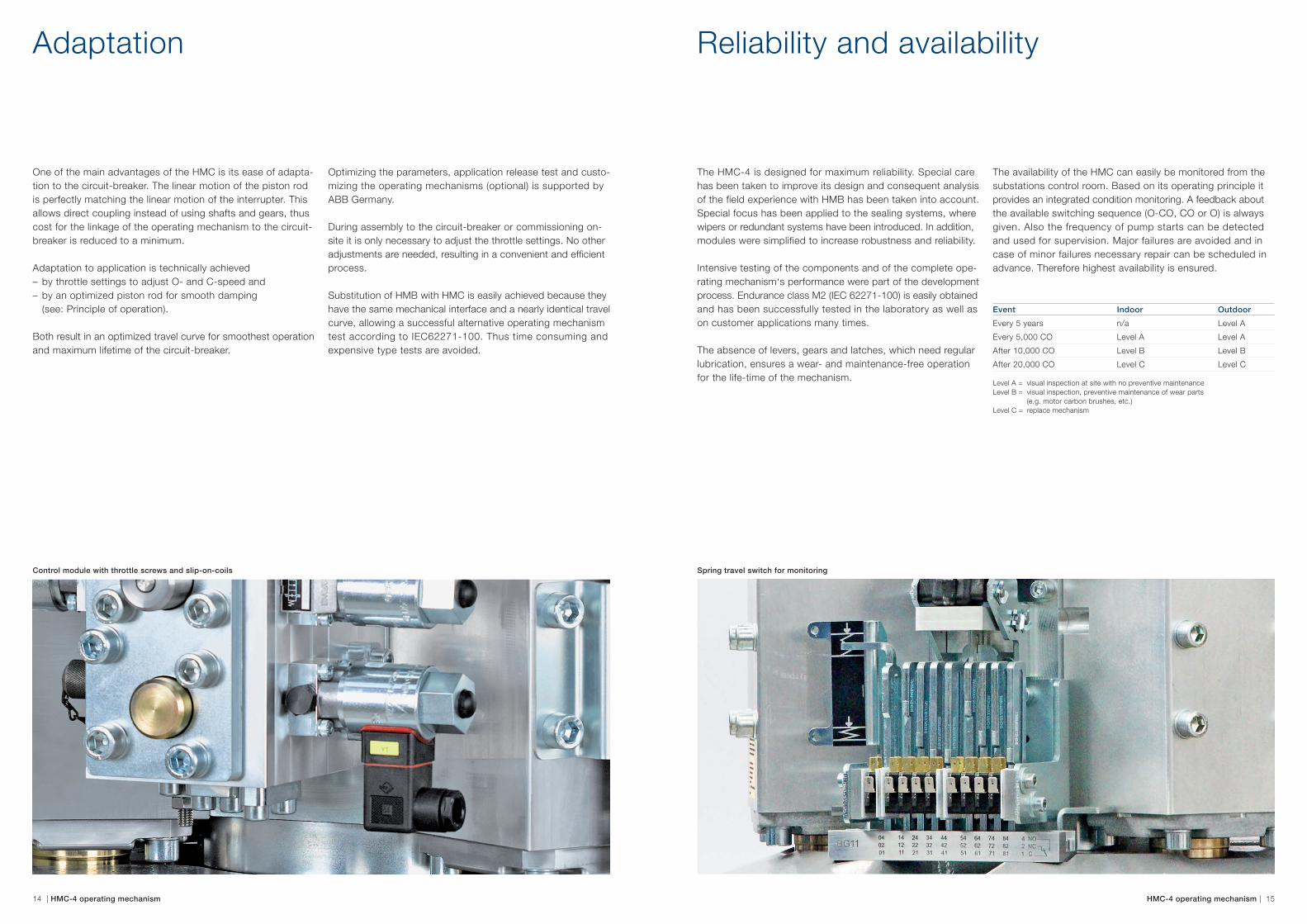
Adaptation
One of the main advantages of the HMC is its ease of adapta-tion to the circuit-breaker. The linear motion of the piston rod is perfectly matching the linear motion of the interrupter. This allows direct coupling instead of using shafts and gears, thus cost for the linkage of the operating mechanism to the circuit-breaker is reduced to a minimum.
Adaptation to application is technically achieved – by throttle settings to adjust O- and C-speed and – by an optimized piston rod for smooth damping (see: Principle of operation).
Both result in an optimized travel curve for smoothest operation and maximum lifetime of the circuit-breaker.
Optimizing the parameters, application release test and custo-mizing the operating mechanisms (optional) is supported by ABB Germany.
During assembly to the circuit-breaker or commissioning on- site it is only necessary to adjust the throttle settings. No other adjustments are needed, resulting in a convenient and efficient process.
Substitution of HMB with HMC is easily achieved because they have the same mechanical interface and a nearly identical travel curve, allowing a successful alternative operating mechanism test according to IEC62271-100. Thus time consuming and expensive type tests are avoided.
Reliability and availability
The HMC-4 is designed for maximum reliability. Special care has been taken to improve its design and consequent analysis of the field experience with HMB has been taken into account. Special focus has been applied to the sealing systems, where wipers or redundant systems have been introduced. In addition, modules were simplified to increase robustness and reliability.
Intensive testing of the components and of the complete ope-rating mechanism‘s performance were part of the development process. Endurance class M2 (IEC 62271-100) is easily obtained and has been successfully tested in the laboratory as well as on customer applications many times.
The absence of levers, gears and latches, which need regular lubrication, ensures a wear- and maintenance-free operation for the life-time of the mechanism.
The availability of the HMC can easily be monitored from the substations control room. Based on its operating principle it provides an integrated condition monitoring. A feedback about the available switching sequence (O-CO, CO or O) is always given. Also the frequency of pump starts can be detected and used for supervision. Major failures are avoided and in case of minor failures necessary repair can be scheduled in advance. Therefore highest availability is ensured.
Event Indoor Outdoor
Every 5 years n/a Level A
Every 5,000 CO Level A Level A
After 10,000 CO Level B Level B
After 20,000 CO Level C Level C
Level A = visual inspection at site with no preventive maintenance Level B = visual inspection, preventive maintenance of wear parts (e.g. motor carbon brushes, etc.)Level C = replace mechanism
Control module with throttle screws and slip-on-coils Spring travel switch for monitoring

16 | HMC-4 operating mechanism HMC-4 operating mechanism | 17
Operational excellence
Operational excellence in all processes from sales to manu-facturing is a key success factor. 5S, KanBan, FiFo, electronic torqueing systems and other methods are fully integrated in the modern flow production line, which is controlled by a manufacturing execution system (MES). The traceability of the most components is guaranteed by the use of 2D matrix codes, which also ensure the conformance with the customer´s request specified in the order documents. Finally a 100 % routine test verifies that the product will meet the high expecta-tion of the customer.
MES provides at each workstation: – login for qualified workers only – necessary order information for 100 % conformity – documents like – BOM’s – drawings – instructions – interface for electronic torqueing system MES records at each workstation: – verification of correct torqueing – 2D matrix code of main components for traceability – progress tracking (online)
1 2
Quality
Field experience from more than 990,000 operating years has resulted in the HMC-4 design. The development work was supported by tools for simulation as well as design- and pro-cess-FMEA. Thorough type testing verifies the high reliability of this mechanism: Component tests, environmental tests, and several M2 tests on applications, even far above 10,000 CO, have been successfully passed.
Operational excellence in production is a key success factor and the 100 % routine test results in a continuously high quality level of the product. The experience and ideas of our emplo-yees are a great contribution for improving our processes. To give only one example: The continuous improvement process (CIP) is part of our daily work. The engineering support by ABB Germany during the adaptation process to the circuit-breaker results in an optimized and wear-free operation of the equipment. Minimum maintenance is also a benefit for the customer. For the first 10,000 CO-operations, besides visual inspection, no maintenance is required.
Extensive training courses for staff of the switchgear manufac-turers and for the end users of the HMC ensure a professional approach to the product. This is the final step to guarantee reliable switching over the whole life time.
1 2D matrix code | 2 Electronic torqueing CIP board in main assembly area

18 | HMC-4 operating mechanism HMC-4 operating mechanism | 19
Training
The operating mechanism is, besides the interrupter itself, the most important component of a circuit-breaker.
ABB has taken this high importance into account and is continuing the success of the HMB technology with the newly developed HMC operating mechanism. This supports all users who are sharing this focus on performance and reliability of the operating mechanism.
Environmental protection and decommissioning
To ABB, environmental protection is an important element of corporate culture. Therefore, ABB AG is certifi ed in accordance with ISO 14001 and has committed itself to comply with the ICC Charter.
Energy efficiency, careful use of materials, avoidance of toxic and environmentally incompatible materials are maintained over the entire product life cycle. Starting from the production of the raw materials to the possible reuse after decommissio-ning.
A B C
To make the most out of the performance of the HMC opera-ting mechanisms, having trained personnel is a key success factor.
ABB provides this training in different levels (shown in the figure below). A thorough understanding of the mechanism´s principle and design ensures a professional and effi cient reac-tion of the customers staff when operating, maintaining and servicing the mechanism. For all levels experienced trainers and professionals are available at our training facilities.
If the operating mechanism is not reused for the same purpose after the switchgear is decommissioned a spring press is to be used to dispose the operating mechanism properly. The materials occurring in this process should be recycled to the maximum extent.
It is possible to assign ABB for the decommissioning.
”Expert”Expert is about how to assemble and disassemble the product in all details.
”Service”Service is about maintenance and repair by using the available exchange modules.
Hands on training how to install and test the mechanism.
”Basics”Basics is about the product and its working principles. The training is theoretical.
HMC as part of the switchgear
Sorting components and materials, recycling
Decommissioning and disassembly
Production
Production of raw materials

Contact us
ABB AG High Voltage ProductsBrown-Boveri-Strasse 3063457 Hanau-Grossauheim, Germany www.abb.com/highvoltage
1HD
X58
0510
Rev
C e
n pr
inte
d in
Ger
man
y (0
8.15
-100
-NIN
O)
Note:We reserve the right to make technical changes or modify the contents of this document without prior notice. With regard to purchase orders, the agreed particulars shall prevail. ABB AG does not accept any responsibility whatsoever for potential errors or possible lack of information in this document.
We reserve all rights in this document and in the subject matter and illustrations contained therein. Any reproduction, disclosure to third parties or utilization of its contents – in whole or in parts – is forbidden without prior written consent of ABB AG.
Copyright© 2015 ABBAll rights reserved
Please consider the environment before printingthis document.
Operating mechanism on the Web To get more information, install QR code reader on your mobile device, scan the code and see more.