Embed Size (px)
Citation preview

Copyright 2011 Carrier Corporation Form 40UV,UH-4PD
Carrier delivers unit ventilators that meet the strict indoor air quality re-quirements of schools, hospitals, and institutions.• Vertical and horizontal designs
provide heating, cooling and dehumidification solutions for a variety of applications
• Quiet fan system offers an ideal solution for sound-sensitive applications, such as classrooms
• Dehumidification capabilities, air filtration techniques, and a sealed insulation design ensure indoor air quality
• Modular design provides enhanced structural rigidity for long trouble-free operation and simplified maintenance
• Chilled water, hot water, steam and DX (direct expansion) coils are constructed of aluminum fins mechanically bonded to copper tubes for peak heat transfer (electric resistance heating is also available)
• Heavy gage, die-formed galvanized steel frame ensures rugged dependability, exact panel fit, precise component alignment and long-term structural integrity
• Tamper resistant hex head panel fasteners offer easy service access without special tools
• Large compartments for wiring and piping simplify maintenance procedures
Features/BenefitsThe 40UV and 40UH unit ventilators are compact, efficient, and easy to install.
The superior design features of 40UV and 40UH units provide economical, dependable, long-term performance.
AIRSTREAM™40UV,UH050-200Unit Ventilators
500 to 2000 Nominal Cfm
ProductData
40UH
40UV

2
Indoor air qualityThe combination of features found in 40UV and 40UH unit ventilators en-sures that only clean, healthy, condi-tioned air is delivered to the occupied space. Ventilation rate is certified per AHRI (Air Conditioning, Heating, and Refrigeration Institute) Standard 840 by an independent laboratory.One-piece filter cleans the air before it is introduced into the room. Unit is shipped with a 1-in. throwaway filter and can accept permanent or renew-able media filters. Filter track may be adjusted to accept field-supplied 2-in. filter.Combination outdoor/return air damper, standard on all units, pro-vides positive control of ventilation air. Extruded aluminum damper is insulat-ed with closed cell foam insulation.
Double sloped condensate drain pan can be configured for right-hand or left-hand drain connection in the field. Drain connection size 7/8 in. OD copper.Cooling coil has a full-depth design. When combined with available face and bypass damper, the coils prevent the build-up of humidity in the room, even during part load conditions.Precision fan system provides quiet operation in environments where sound control is critical, such as classrooms. Sound level is certified by an independent laboratory per AHRI Standard 350.Die-formed, heavy-gage steelcabinet provides secure, dent-resistant protection for internal com-ponents. Cabinet exterior has abaked-on polyurethane powder-coated finish for corrosion resistance and en-hanced appearance.
Front access panels are secured with hex-head fasteners to provide tamper-resistance while maintaining easy maintenance and service access.Efficient direct-drive motor prevents alignment problems. Blowers share a common hollow shaft connected to the motor with a resilient coupling.Steel blower housings are securely mounted to a die-formed galvanized steel blower deck.Self-aligning bearings, vibration isolating motor mounts and flexi-ble drive shaft coupling isolate the rotating components from the rest of the unit to ensure quiet vibration-freeoperation.Mechanically bonded aluminum fin coils provide improved heat trans-fer with corrosion and vibration resis-tance. Copper tubes are standard.
Features/Benefits (cont)
DIRECT DRIVE FANMOTOR
CONDENSATEDRAIN CONNECTORS
DAMPERACTUATOR COMBINATION OA/RA
DAMPER
DISCONNECTSWITCH*
FAN SPEEDSWITCH*
FUSE(S)*
SERVICE SWITCH*
* SEE 40UV,UH INSTALLATION, START-UP AND SERVICE INSTRUCTIONSADDITIONAL INFORMATION.
*See 40UV,UH Installation, Start-Up and Service Instructions for additional information.
DIRECT DRIVE FANMOTOR
CONDENSATEDRAIN CONNECTORS
DAMPERACTUATOR COMBINATION OA/RA
DAMPER
DISCONNECTSWITCH*
FAN SPEEDSWITCH*
FUSE(S)*
UNIT VENTILATOR CONSTRUCTION
*See 40UV,UH Installation, Start-Up and Service Instructions for additional information.
a40-1671

3
Enhanced performance and safetyDraw-thru blower arrangement distributes air across entire coil face for uniform discharge temperatures. Draw-thru design also eliminates hot spots in electric heat coil to maximize heating element life.Efficient direct drive helps to main-tain low operating costs and also re-duces maintenance requirements.Wide selection of factory-installed coils includes chilled and hot water, DX, steam, and electric resistance heat coils.Motor and control protection is provided by cartridge fuses. Units are ETL listed to UL Standard 1995.Safety cutouts and interlock switches ensure safe performance. Fan must be operating before optional
electric heat is turned on. Electric heat is turned off in case of high-heat conditions.
Economical operationThe 40UV and 40UH Series unit ventilators not only have low initial costs, but they also save money by reducing installation expense and providing long-term energy-efficient performance.Quick installation provided by built-in levelers, drain pan connections on both ends of the unit, and reversible coil hand without unit modification.Permanent split capacitor (PSC) motors are standard on size 50 to 150 units (500 through 1500 cfm).Electronically commutated (ECM) blower motor option saves energy and overload protection with automatic reset ensures reliability. The ECM
motor is standard on all size 200 units (2000 cfm). The ECM motor is also provided for units with high static pres-sure application or units with the UV Open controller option or units with field supplied and installed controls. Motors are mounted out of the air-stream so they are not subject to coil heat, extending the life of the motor.High-efficiency, precision-balanced blowers minimize air tur-bulence, surging and vibration tominimize operating expenses.Mixing dampers control the blend of outside air and room air to achieve comfort levels. When the outside air is suitable, outside air dampers can fully open to provide free cooling.Fewer moving parts lower operating costs by enhancing reliability and mak-ing service easier.
Table of contentsPage
Features/Benefits . . . . . . . . . . . . . . . . . . . . . . . . . . . . . . . . . . . . . . . . . .1-3Model Number Nomenclature . . . . . . . . . . . . . . . . . . . . . . . . . . . . . . . . . .4-9AHRI Capacity Ratings. . . . . . . . . . . . . . . . . . . . . . . . . . . . . . . . . . . . . . . 10Physical Data . . . . . . . . . . . . . . . . . . . . . . . . . . . . . . . . . . . . . . . . . . . . . 10Options and Accessories. . . . . . . . . . . . . . . . . . . . . . . . . . . . . . . . . . . .11-13Base Unit Dimensions . . . . . . . . . . . . . . . . . . . . . . . . . . . . . . . . . . . . .14-24Accessory Dimensions . . . . . . . . . . . . . . . . . . . . . . . . . . . . . . . . . . . . .25-45Selection Procedure . . . . . . . . . . . . . . . . . . . . . . . . . . . . . . . . . . . . . . . . . 45Performance Data . . . . . . . . . . . . . . . . . . . . . . . . . . . . . . . . . . . . . . . .46-77Electrical Data . . . . . . . . . . . . . . . . . . . . . . . . . . . . . . . . . . . . . . . . . . .78-84Application Data . . . . . . . . . . . . . . . . . . . . . . . . . . . . . . . . . . . . . . . . .85-89Guide Specifications. . . . . . . . . . . . . . . . . . . . . . . . . . . . . . . . . . . . . . .90-94

4
BASE UNIT MODEL NUMBER
Inlet ArrangementsHorizontal UnitsA – Bottom RA, Top OA D – Rear RA, Top OAB – Bottom RA, Rear OA E – Rear RA, Rear OAC – Bottom RA, No OA F – Rear RA, No OA
Vertical Units
165/8 in. 165/8 in. CABINET, CABINET DESCRIPTION FRONT DRAFT STOP RA RA A L Rear OA, Open Piping Tunnel B M Rear OA, Closed Piping Tunnel C N Bottom OA, Open Piping Tunnel D O No OA, Open Piping Tunnel
217/8 in. 217/8 in. CABINET, CABINET DESCRIPTION FRONT DRAFT STOP RA RA E P Rear OA, Piping Passage Unit F R Rear OA, Full Adapter Back G S Top OA, Full Adapter Back H T Bottom OA, Open Adapter Back I U No OA, Open Adapter Back J W 21/2 in. Step Down Pipe Pass Adapter Back K Y 21/2 in. Step Down Full Adapter Back
Discharge AirHorizontal UnitsA – Front Discharge Bar Stock Grille*B – Front Discharge Grille with Screen*C – Front Discharge Duct Collar (No Grille)*D – Front Discharge Duct Collar with Plenum (No Grille)†E – Front Discharge Double Deflection Grille with Plenum†F – Bottom Discharge with Double Deflection Grille**
Vertical UnitsA – Top Discharge Bar Stock Steel GrilleB – Top Discharge Grille with ScreenC – Top Discharge Duct Collar (No Grille)
F – UH/UV Current Design
Fan Motor Selection1 – PSC - Standard2 – ECM - High-Efficiency Motor5 – ECM - Variable Speed Motor
Face and Bypass Damper1 – No Damper2 – Face and Bypass Damper
Outdoor Air Damper1 – Standard Damper Assembly2 – Standard Damper Assembly with Locking Quadrant3 – Cold Weather Damper Assembly4 – Cold Weather Damper Assembly with Locking Quadrant5 – No Outdoor Air Damper (Recirculation Only)
Temperature Control TypeA – No ControlsD-H – DDC ReadyJ-3 – Carrier UV Open ControlsX
SEE NEXT PAGEFOR REMAINDER
OF MODELNUMBER
NOMENCLATURE
1 BC F G B F A 1 AF
– Factory-Installed Controls by Others
(1-in. Thick)
Paint Options
See next page for legend and footnotes. A40-1672
Model number nomenclature

5
BASE UNIT MODEL NUMBER (cont)
WarrantyA – One Year
Heating Coil TypeA B-J – Hot Water Same End ConnectionsM-R – Steam Same End ConnectionsS-W – Steam Opposite End Connections3-6 – Electric Heat Right Hand Coil Connection
Coil Arrangements1 – H/W Position 1, C/W Position 2 (PreHeat)2 – H/W Position 2, C/W Position 1 (ReHeat)
0 – Not Used
Power Supply / DisconnectJ – 115-1-60 (Standard)K – 208-1-60L – 240-1-60M – 277-1-605 – 208-3-60 (3-Wire)6 – 240-3-60 (3-Wire)7 – 460-3-60 (3-Wire)
SEE PREVIOUS PAGEFOR REMAINDER
OF MODELNUMBER
NOMENCLATURE
1 BC F G B F A 1 A1 AA B 1 2 2 M 0 J40 UV F 3 P
Filter Option1 – 1-in. Throwaway Filter2 – 1-in. Renewable Filter3 – 1-in. Permanent Filter4 – 2-in. Pleated Filter
Drain Pan OptionA – Galvanized Drain PanB – Stainless Steel Drain Pan
Cooling Valve Piping PackageA – NoneB-E F-J – Packages used with 3-Way ValveX – 2 or 3-Way Special Piping Package
Cooling Valve / ActuatorA – NoneB-G – 3-Way Modulating Valve / ActuatorH – 3-Way, 2-Position Valve††J-O – 2-Way Modulating Valve / ActuatorP – 2-Way, 2-Position Valve††
Cooling Coil TypeA – NoneF-L – Cold Water Same End Connections8,9 Y,Z,2,3 – Direct Expansion
Heating Valve Piping PackageA – NoneB-E F-J – Packages used with 3-Way ValveX – 2 or 3-Way Special Piping Package
Heating Valve / ActuatorA – NoneB-G – 3-Way Modulating Valve / ActuatorH – 3-Way, 2-Position Valve††J-O – 2-Way Modulating Valve / ActuatorP – 2-Way, 2-Position Valve††1-6 – Steam, 2-Way Modulating Valve / ActuatorP – Steam, 2-Way, 2-Position Valve
– None
– Packages used with 2-Way Valve
– C/W High Capacity Same End Connections
– Packages used with 2-Way Valve
LEGENDDDC — Direct Digital ControlsECM — Electronically Commutated MotorOA — Outside AirPSC — Permanently-Split CapacitorRA — Return Air
*Available for 301/2 in. horizontal units only.†Available for 36 in. (40 in. for size 200) horizontal units only.**Available for 40 in. (44 in. for size 200) horizontal units only.††Face and bypass units only.
A40-1673

6
STORAGE CABINET PART NUMBERS*
FILLER SECTION PART NUMBERS*
Model number nomenclature (cont)
SC 21 1 F3 D S 2 42 1
Storage Cabinet
Depth 21 — 21-7/8 in.16 — 16-5/8 in.
Model 1 — Standard2 — Standard with Pipe Chase4 — Standard with Louvered Inlet and Outlet5 — Standard with Aluminum Extrusion Draft Stop Inlet6 — Standard with Louvered Inlet and Aluminum
Extrusion Outlet 7 — Shallow Shelf with Pipe Chase†
T ops F1 — White FormicaF2 — Black FormicaF3 — Fog FormicaF4 — Folkstone FormicaF5 — Almond Papyrus FormicaF6 — Almond FormicaF7 — Pumice FormicaCF — Custom FormicaTX — Charcoal Texture Paint NT — No Top
Doors O — OpenD — DoorsL — Doors with Lock
Material Thickness S — Standard 18 gageH — Heavy Duty 16 gage
Length 2 — 2 ft3 — 3 ft4 — 4 ft5 — 5 ft
Color Standard Custom41 — Beige42 — Polar Ice
46 — White
43 — Gray CM — Custom Match
Interior 1 — Standard Single Shelf2 — Second Shelf3 — Tote Trays
8 — Shallow Shelf with Louvered Outlet†9 — Shallow Shelf with Louvered Inlet and Aluminum
Extrusion Outlet†
a40-1659
SC F2 21 F3 42
Storage Cabinet
AccessoryF1 — Filler Panel 12 in.F2 — Filler Panel 18 in.F3 — Filler Panel 24 in.
CF — Corner FillerEP — End Panel
Depth21 — 21-7/8 in.16 — 16-5/8 in.
TopsF1 — White FormicaF2 — Black FormicaF3 — Fog FormicaF4 — Folkstone FormicaF5 — Almond Papyrus FormicaF6 — Almond FormicaF7 — Pumice FormicaCF — Custom FormicaTX — Charcoal Texture Powder Coated SteelNT — No Top00 — End Panel
ColorStandard Custom41 — Beige
42 — Polar Ice 46 — White
43 — Gray CM — Custom Match
BA — Back Angle
*To order, contact your Carrier Sales representative.†Available for 165/8 in. depth only.

7
DRAFT STOP PART NUMBERS*
DRAFT STOP ACCESSORY PART NUMBERS*
DS 24 FT S P 4 42
Draft Stop
Height12 — 12 in.20 — 20 in.24 — 24 in.
Grille TypeFT — Flat Top (Louvered) Inlet BG — Aluminum Extrusion Bar Grille Inlet
Material ThicknessS — Standard 18 gageH — Heavy Duty 16 gage
Back PanelP — Partial Back PanelF — Full Back Panel
Length2 — 2 ft3 — 3 ft4 — 4 ft5 — 5 ft6 — 6 ft
ColorStandard Custom41 — Beige 45 — Brick Red42 — Polar Ice 46 — White43 — Gray CM — Custom Match
DS T3 20 42
Draft Stop
AccessoryT3 — Trim Strip 3-1/2 in.T7 — Trim Strip 7-1/2 in.OC — Outside CornerIC — Inside CornerEL — End Cap LeftER — End Cap Right
Height12 — 12 in.20 — 20 in.24 — 24 in.
ColorStandard Custom41 — Beige42 — Polar Ice
46 — White
43 — Gray CM — Custom Match
*To order, contact your Carrier Sales representative.

8
PIPE ENCLOSURE PART NUMBERS*
PIPE ENCLOSURE ACCESSORY PART NUMBERS*
PE CB 4 11 S 45 42
Pipe Enclosure
Model CB — Closed Bottom
Depth4 — 4 in.5 — 5 in.
Material Thickness S — Standard 18 gageH — Heavy Duty 16 gage
Length 10 — 1 ft 30 — 3 ft15 — 1.5 ft 35 — 3.5 ft20 — 2 ft etc., in 1/2 ft increments up to25 — 2.5 ft 80 — 8 ft
Color Standard Custom41 — Beige42 — Polar Ice
46 — White
43 — Gray CM — Custom Match
Height08 — 8 in.11 — 11 in.14 — 14 in.20 — 20 in.
a40-1660
*To order, contact your Carrier Sales representative.a40-1661
PE CB T3 4 11 42
Pipe Enclosure
Model CB — Closed Bottom
AccessoryT3 — Wall Trim 3-1/2 in. wide T7 — Wall Trim 7-1/2 in. wide OC — Outside CornerIC — Inside CornerEL — End Cap LeftER — End Cap Right
Depth 4 — 4 in.5 — 5 in.
Height 08 — 8 in.11 — 11 in.14 — 14 in.20 — 20 in.
Color Standard Custom41 — Beige42 — Polar Ice
46 — White
43 — GrayCM — Custom Match
Model number nomenclature (cont)
*To order, contact your Carrier Sales representative.
9
SINK AND BUBBLER PART NUMBERS*
TOUCH-UP PAINT PART NUMBERS*
BC SS S DB 42
Sink and Bubbler
TopsF1 — White FormicaF2 — Black FormicaF3 — Fog FormicaF4 — Folkstone FormicaF5 — Almond Papyrus FormicaF6 — Almond FormicaF7 — Pumice FormicaCF — Custom FormicaSS — Stainless Steel
Material ThicknessS — Standard 18 gageH — Heavy Duty 16 gage
ColorStandard Custom41 — Beige42 — Polar Ice
46 — White
43 — Gray CM — Custom Match
ADA — Americans with Disabilities Act
Sink and BubblerDB — Double Bowl (bowl with bubbler & bowl with faucet), ADA Approved FixturesSB — Single Bowl (bowl with bubbler & faucet), ADA Approved Fixtures
TU SP 42
Touch Up
Paint TypeSP — Spray Paint
ColorStandard Custom41— Beige42 — Polar Ice
46 — White
43 — Gray CM — Custom Match
*To order, contact your Carrier Sales representative.

10
*Air Conditioning, Heating, and Refrigeration Institute.†40UV only.**40UH only.
NOTES:1. Ratings are in accordance with AHRI Standard 840.2. All units are equipped with a 3-row coil.3. Water temperature rise is 10 F, with entering water temperature of
45 F.4. Entering air temperature is 80 F dry bulb, 67 F wet bulb.
Physical data40UV,UH
LEGENDDX — Direct Expansion
*40UV only.†40UH 43 1/2 and 47 1/2 in. deep units only.**Weight based on damper-controlled unit with 5-row coil and factory-
installed controls.
40UV,UH UNIT SIZE NOMINAL CFM
ACTUALCFM
TOTAL(Btuh)
SENSIBLE CAPACITY
(Btuh)
VENTILATION RATE (%)
050† 500 490 8,300 6,400 80
075 750 750 19,400 12,900 80
100 1000 1000 26,300 19,100 80
125 1250 1210 33,500 23,600 80
150 1500 1500 40,200 28,100 80
200** 2000 2010 65,000 42,000 80
UNIT 40UV,UH 050* 075 100 125 150 200†NOMINAL AIRFLOW (Cfm) 500 750 1000 1250 1500 2000FANS
Quantity 1 2 3 4 5 5Diameter (in.) 8.32 8.32 8.32 8.32 8.32 9.5Width (in.) 8 8 8 8 8 6
40UV FILTERSNominal Size (in.) (1 in. thick) 91/4 x 241/4 91/4 x 361/4 91/4 x 481/4 91/4 x 601/4 91/4 x 721/4 —Nominal Size (in.) (2 in. thick) 91/4 x 241/4 91/4 x 361/4 91/4 x 481/4 91/4 x 601/4 91/4 x 721/4 —Quantity 1 1 1 1 1 —
40UH FILTERSNominal Size (in.) (1 in. thick) — 93/4 x 361/4 93/4 x 481/4 93/4 x 601/4 93/4 x 721/4 93/4 x 721/4Nominal Size (in.) (2 in. thick) — 93/4 x 361/4 93/4 x 481/4 93/4 x 601/4 93/4 x 721/4 93/4 x 721/4Quantity — 1 1 1 1 1
40UV SHIPPING WEIGHT**(Approx lb)
165/8 in. Deep Unit 330 400 480 590 660 —217/8 in. Deep Unit 340 410 490 605 675 —
40UH SHIPPING WEIGHT**(Approx lb)
34 in. Deep Unit — 420 500 620 690 —391/2 in. Deep Unit — 500 600 740 830 —431/2 in. Deep Unit — 530 640 790 880 1020471/2 in. Deep Unit — — — — — 1050
40UV INSTALLED WEIGHT**(Approx lb)
165/8 in. Deep Unit 315 380 460 570 640 —217/8 in. Deep Unit 325 390 470 595 655 —
40UH INSTALLED WEIGHT**(Approx lb)
34 in. Deep Unit — 405 480 600 670 —391/2 in. Deep Unit — 485 580 720 810 —431/2 in. Deep Unit — 515 620 770 860 1000471/2 in. Deep Unit — — — — — 1030
COIL WATER WEIGHT(Approx lb per row of coil) 1.0 1.5 2.0 2.4 2.7 2.7
COIL CONNECTIONS (in. OD) Return SupplyWater Coils with 1 to 5 Rows 7/8 7/8Steam Coils (All Units) 7/8 11/8
Suction LiquidDX Coils 7/8 3/8
CONDENSATE DRAIN 7/8
AHRI* capacity ratings

11
40UV, UH OPTIONS AND ACCESSORIES
LEGEND *Factory-installed option.†Factory-supplied, field-installed option.**Field-installed or factory-supplied, field-installed option with an ETO (Engineered to Order) request.
ITEM OPTION* ACCESSORIES† ACCESSORIES**Adapter Back XBar Stock with Screen XUV Open Controls XChilled Water Coil XDDC Ready Controls XDischarge Duct Collar XDouble Deflection Grille XDraft Elimination Return XDX Coils XECM Motor XElectric Resistance Heat Coils XFace and Bypass Damper XHeavy Gage Exterior Panel XHot Water Coil XOutside Air Damper XPaint Color XPipe Tunnel XStainless Steel Drain Pan XSteam Coil XFilters X XBarometric Relief Damper XBarometric Relief Damper Louver XEnd Panels XOutside Air Louvers XUnit Subbase XUtility Compartment XValve Package XDraft Stop Enclosure XFiller Section XIAQ Sensor (CO2) XPipe Enclosure XPower Exhauster XSink and Bubbler XStorage Cabinet XTemperature Sensors XTouch-Up Paint X
DDC — Direct Digital ControlsDX — Direct ExpansionECM — Electrically Commutated MotorIAQ — Indoor Air QualityUV — Unit Vent
Options and accessories

12
Factory-installed optionsControls are factory-mounted, factory-wired and factory-tested. Direct Digital Control (DDC) packages can beprovided for a variety of unit configurations and complywith ASHRAE (American Society of Heating, Refrigeratingand Air Conditioning Engineers) control cycle I, II, or IIIrecommendations. These controls provide integrated sys-tem operation and are compatible with Carrier’s i-Vu®
Open control system or a BACnet* building automationsystem. Carrier’s Unit Vent Open Controller is an integrat-ed component of a Carrier unit ventilator. The Unit VentOpen controller continuously monitors and regulates unitventilator operation with reliability and precision. This ad-vanced controller features a sophisticated, factory-engi-neered control algorithm that provides optimum perfor-mance and energy effciency. The Unit Vent Open control-ler also features plug-and-play connectivity to Carrier’s i-VuOpen Control System. The Carrier i-Vu Open Control Sys-tem combines state-of-the-art Carrier equipment, plug-and-play controllers, and the powerful, web-based i-Vu user in-terface to form a cohesive, intuitive, and fully integratedBACnet Building Automation System. For added flexibili-ty, the Unit Vent Open controller is capable of stand-aloneoperation. Application features include built-in advancedcontrol routines for zone level demand control ventilationand automatic fan speed control based on actual heating orcooling requirements. System benefits include demandlimiting support for maximum energy savings. Hardwarefeatures include on-board hardware clock, remote occu-pancy input, and support for space temperature thermistorsensor for stand alone operation.
For additional information on the Unit Vent Openfactory-mounted controller, refer to product data sheet 11-808-469-01 and installation and start-up guide catalog no.11-808-476-01. Factory-mounted controls supplied byothers are also available by special request.
Three standard ventilation cycles:• ASHRAE Cycle I: Admits 100% outdoor air at all times.• ASHRAE Cycle II: Most common control cycle.• ASHRAE Cycle III: Variable outdoor-air cycle.NOTE: Factory-installed controls by other option must bequoted on a job-by-job basis. Factory may wire controlsand actuator based on request. However, setting the actua-tor (switch settings, tightening clamp to damper shaft,torque pre-loading, etc.) is the responsibility of thecustomer.Direct Digital Controls (DDC) ready control packageoption is a pre-wired offering of selected control compo-nents. These components are factory-wired to a terminalstrip located in the left-hand end package of the unitventilator.
The unit is shipped from the factory with an ETL listing,in addition to the following features:• A NEC (National Electrical Code) Class 2 type
transformer.• Double pole, single throw (DPST) fan start/stop
capability.
*Sponsored by ASHRAE (American Society of Heating, Refrigeratingand Air Conditioning Engineers).
• Outdoor air/return air actuator or face and bypassdamper actuator: 3-point floating, 2 to10 vdc or 4 to20 mA.
• A chilled water or direct expansion cooling coil low tem-perature detection thermostat.
Discharge duct collar option allows easy ductworkmounting to horizontal unit discharge.Electric resistance heat coils have capacities rangingfrom 4.2 to 24 kW and are factory-installed options. Allheat coils have automatic and manual high limit cutouts.Face and bypass damper is used to control the amountof air sent through the heating or cooling coils. The faceand bypass damper is constructed of aluminum with doubleedge blade seals.Filter options include permanent washable elements orrenewable media with a frame. All filters are nominal 1-in.or 2-in. widths. Standard 1-in. filter track may be adjustedto accept field-supplied 2-in. filter. Low-limit thermostat (LLT) is factory-installed andfactory-wired on all units with water coils. The sensor shutsdown the fan circuit if the mixed-air temperature fallsbelow the factory setting of 38 F, which prevents thehydronic coils from freezing. The LLT, a 12-ft capillarytube in the airstream, provides SPDT contact and ismounted on the leaving-air side of the coil. When installedon DX coil units as a factory-installed option, the LLToperates when the temperature falls below 28 F.
Field-installed accessoriesBarometric relief damper or power exhauster acces-sories can be used with the unit ventilator system toeliminate positive pressure in the building and promotebetter air exchange for indoor air quality.Cabinet filler sections include top panels, end panels,inside corners and non-standard paint colors which providehidden space for piping and controls, as well as functionalcounter space compatible with storage cabinets. Coordi-nated finishes ensure a seamless, custom appearance inthe unit ventilator and architectural accessory installation.Draft stop enclosure (draft eliminator) accessorydraws unit ventilator inlet air along window walls to createa thermal barrier between the room and outside wall,eliminating cold window downdrafts and occupancydiscomfort. Draft stop enclosures can stand alone or beincorporated into the back of storage cabinet sections.Filter options include permanent washable elements orrenewable media with a frame. All filters are nominal 1-in.or 2-in. widths. Standard 1-in. filter track may be adjustedto accept field-supplied 2-in. filter. Indoor air quality (CO2) sensor is available as awall-mounted, field-installed accessory. The sensor usesinfrared technology to detect the levels of CO2 present inthe conditioned space. This information is used to modifythe position of the outdoor-air dampers to admit moreoutdoor air as required to provide the desired ventilationrate. An isolated field-supplied transformer is required toprovide power to sensor.
Options and accessories (cont)

13
Louvers are available for exterior wall openings in avariety of styles. Decorative grille accessory provides anarchitectural finish. Pipe enclosure accessories carry and conceal supplyand return piping to and from the unit ventilator. Theaccessories, available in the same color as the unit ventila-tor, contribute to a neat appearance by covering exposedpiping.Sink and bubbler units handle any type of classroomapplication. Compatible with storage cabinets and fillersections, they can also provide continuous surface area forthe room perimeter installation.
Storage cabinets accommodate books and supply stor-age along window walls. Manufactured from tough cold-rolled steel, reinforced for additional strength, and finishedwith a durable powder coat, they will withstand the abuseof a classroom environment.Temperature sensors are available for wall mounting.Accessory wall-mounted space temperature sensor areavailable for field installation and wiring.Valve packages provide cooling and heating modulationfor hydronic coils. Both 2-way and 3-way valve packagesare available in a wide range of Cv factors and connectionsizes. Pneumatic valves are not available.
UNIT VENTILATOR
A
B
C
D
E
F G
H
I
UNIT VENTILATOR ARCHITECTURAL ACCESSORIES INSTALLATION EXAMPLE
LEGENDA — Pipe EnclosureB — Draft-Stop EnclosureC — Cabinet with Draft StopD — Corner Filler PanelE — Cabinet with False BackF — Sink and BubblerG — Filler SectionH — Cabinet with Finned OutletI — Removable End Panel

14
40UV — 165/8-in. DEEP UNIT (STANDARD)
NOTES:1. All dimensions are in inches.2. Dimension does not include end panels.3. Three front panels provided for service access.4. Motor and electrical power input box on right side of
unit. Box includes fan speed switch, and non-fuseddisconnect switch.
5. Connection hand is determined by facing discharge ofunit.
UNIT40UV
AIRFLOW(cfm)
DIMENSIONS (in.) APPROXIMATESHIPPING
WEIGHT (lb)
APPROXIMATEINSTALLEDWEIGHT (lb)W1 W2 W3
050 500 50 24 16.60 330 315075 750 62 36 31.67 400 380100 1000 74 48 46.74 480 460125 1250 86 60 61.81 590 570150 1500 98 72 78.47 660 640
2.95
2.00
12.10 (TYP)
W1(SEE NOTE 2)
1.00(UNIT SHOWN
WITH 1.00" ENDPANELS)
MOTOR
ELECTRICALBOX
RECESSED RETURNAIR/KICK PANEL
FRONT VIEW
NON-FUSEDDISCONNECTSWITCH
FRONT SERVICEPANELS(SEE NOTE 3)
UV OPENCONTROLLER(OPTIONAL)
17.50(TYP)W2
.90
15.00(TYP)18.25
(TYP)
7.00 (TYP)
22.00(TYP)
2.00(TYP)
8.08(TYP-SEENOTE 2)
7.04 (TYP)
1.54 (TYP)
6.75 (TYP)
.75(MOUNTING HOLES-TYP-4 PLACES)
4.50
REAR VIEW
REMOVABLE PANEL( EACH END)
PIPE TUNNEL
OUTSIDE AIR OPENING
PIPING ACCESSOPENING(EACH END)
30.00
27.30
13.90
16.63
7.022.40
RIGHT SIDE VIEW
PIPINGTUNNEL
1.70
16.63W3
5.22
10.61(TYP)
2.08(TYP)
12.37(TYP)
.78(TYP)
TOP VIEW BARSTOCKDISCHARGE GRILLE
REMOVABLE BOTTOM PANEL(EACH END)
A40-1662
Base unit dimensions

15
27.3030.00
19.37
2.40
13.75
7.02
1.74
PIPINGTUNNEL
2.00
3.00
12.00 (TYP)1.00(UNIT SHOWN
WITH 1.00" ENDPANELS)
W1(SEE NOTE 2)
MOTOR
ELECTRICALBOX
RECESSED RETURNAIR/KICK PANEL
NON-FUSEDDISCONNECTSWITCH
FRONT SERVICEPANELS (SEE NOTE 3)
UV OPENCONTROLLER(OPTIONAL)
21.88
1.70
5.20
5.22
W3
10.61(TYP)
12.37(TYP)
2.08(TYP)
5.98(TYP)
TOP VIEW
REMOVABLE BOTTOM PANEL(EACH END)
BARSTOCKDISCHARGE GRILLE
FRONT VIEWEND VIEW
18.25(TYP)
15.00(TYP)
.75(MOUNTING HOLES-TYP-4 PLACES)
17.50(TYP)
7.00 (TYP)
22.00(TYP)
2.00(TYP)
W2
0.90
8.08(TYP-SEENOTE 2)
7.04 (TYP)
1.54 (TYP)
6.75 (TYP)4.50
REAR VIEW
PIPE TUNNEL
OUTSIDE AIROPENING
REMOVABLE PANEL(EACH END)
PIPING ACCESSOPENING(EACH END)
UNIT40UV
AIRFLOW(cfm)
DIMENSIONS (in.) APPROXIMATESHIPPING
WEIGHT (lb)
APPROXIMATEINSTALLEDWEIGHT (lb)W1 W2 W3
050 500 50 24 16.60 340 325075 750 62 36 31.67 410 390100 1000 74 48 46.74 490 470125 1250 86 60 61.81 605 595150 1500 98 72 78.47 675 655
NOTES:1. All dimensions are in inches.2. Dimension does not include end panels.3. Three front panels provided for service access.4. Motor and electrical power input box on right side of
unit. Box includes fan speed switch, and non-fuseddisconnect switch.
5. Connection hand is determined by facing dischargeof unit.
A40-1663
40UV — 217/8-in. DEEP UNIT

16
Base unit dimensions (cont)
40UH — 34-in. DEEP UNIT (Digit Code No. 11 - Option A/B/C)
NOTES:1. All dimensions are in inches.2. Dimension does not include end panels.3. Two bottom panels provided for service access.4. Motor and electrical power input box on right side of unit.
Box includes fan speed switch, and non-fused disconnectswitch.
5. Drawing refers to Design “F” units.
UNIT40UH
AIRFLOW(cfm)
DIMENSIONS (in.) APPROXIMATESHIPPING
WEIGHT (lb)
APPROXIMATEINSTALLEDWEIGHT (lb)W1 W2 W3
075 750 62 36 31.67 420 405100 1000 74 48 46.74 500 480125 1250 86 60 61.81 620 600150 1500 98 72 78.47 690 670
A40-1674
2.00
W1(SEE NOTE 2)
BOTTOM VIEW
LEFT SIDE VIEW
REAR VIEW
W2
0.92
18.59(TYP)21.86
(TYP)
6.75 (TYP)4.50
TOP VIEW
1.70
16.63W3
5.2234
W2
FRONT VIEWBARSTOCKDISCHARGE GRILLE(OPTIONAL)
MOTOR
ELECTRICALBOX
NON-FUSEDDISCONNECTSWITCH
RETURN AIRLOUVERED PANEL(OPTIONAL)
1.00(UNIT SHOWN
WITH 1.00" ENDPANELS)
UV OPENCONTROLLER
(OPTIONAL)
BOTTOM SERVICE PANELS(SEE NOTE 3)
1.54(TYP)
2.10(TYP)
REMOVABLE PANEL(EACH END)
8.08(TYP - SEE NOTE 2)
1.75
5.25
1.72
7.50
OUTSIDE AIROPENING
REAR OUTSIDEAIR OPENING (OPTIONAL)
REAR RETURNAIR OPENING (OPTIONAL)
Ø.75(MOUNTING HOLES
TYP-4 PLACES)
a40-1674

17
16.63
W3 (OPENING)W5(OPENING)
(TO OPENING)
LEFT SIDE VIEW (SIZES 075 TO 150)
BOTTOM VIEW
REAR VIEW
DOUBLE DEFLECTION DISCHARGE GRILLE(OPTIONAL)
W4(TYP)
2.10(TYP)
W8(TYP)
W2
0.92 4.50
.75(MOUNTING HOLES-TYP-4 PLACES)
6.75 (TYP)
1.00 (TYP)
W7(TYP-SEENOTE 2)
3.27(TYP)
TOP OUTSIDE AIROPENING (OPTIONAL)
REMOVABLE PANEL(EACH END)
FRONT VIEW
1.727.50
5.25
W21.75REAR OUTSIDE AIR
OPENING (OPTIONAL)
REAR RETURN AIROPENING (OPTIONAL)
W11.00(UNIT SHOWN
WITH 1.00" END PANELS)
RETURN AIR LOUVERED PANEL(OPTIONAL)
MOTOR ELECTRICALBOX
NON-FUSEDDISCONNECTSWITCH
UV OPENCONTROLLER(OPTIONAL)
BOTTOM SERVICEPANELS(SEE NOTE 3)
TOP VIEW
(SEE NOTE 2)
LEFT SIDE VIEW (SIZE 200)
PIPE TUNNEL
4.00 7.50
39.50
43.50
W6
40UH — 39 1/2 IN. AND 43 1/2 IN. DEEP UNITS WITH FRONT DISCHARGE PLENUM(Digit Code No. 11 - Option D/E)
UNIT40UH
AIRFLOW(cfm)
DEPTH(in.)
DIMENSIONS (in.) APPROXIMATESHIPPING
WEIGHT (lb)
APPROXIMATEINSTALLEDWEIGHT (lb)W1 W2 W3 W4 W5 W6 W7 W8
075 750 36 62 36 36 21.86 7.00 2.31 8.00 4.75 500 485100 1000 36 74 48 48 21.86 7.00 2.31 8.00 4.75 600 580125 1250 36 86 60 60 21.86 7.00 2.31 8.00 4.75 740 720150 1500 36 98 72 72 21.86 7.00 2.31 8.00 4.75 830 810200 2000 40 98 72 72 30.00 10.00 1.44 8.07 4.00 1020 1000
A40-1675
NOTES:1. All dimensions are in inches.2. Dimension does not include end panels.3. Two bottom panels provided for service
access.4. Motor and electrical power input box on right
side of unit. Box includes fan speed switch,and non-fused disconnect switch.
5. Connection hand is determined by facingdischarge of unit.
6. Drawing refers to design “F” series.

18
Base unit dimensions (cont)
W4(TYP)
W8(TYP)
2.10(TYP)
W7(TYP)
W2
0.92 4.506.75 (TYP)
1.00 (TYP)W6
(TYP-SEENOTE 2)
3.27(TYP)
.75(MOUNTING HOLES-
TYP-4 PLACES)
TOP OUTSIDE AIROPENING (OPTIONAL)
REMOVABLE PANEL(EACH END)
FRONT VIEW
BOTTOM VIEW
REAR VIEW
LEFT SIDE VIEW (SIZES 075 TO 150)
1.727.50
5.25
W21.75REAR OUTSIDE AIR
OPENING (OPTIONAL)
REAR RETURN AIROPENING (OPTIONAL)
1.00(UNIT SHOWN
WITH 1.00" END PANELS)
W1
W3(OPENING)
W5 (OPENING)
RETURN AIR LOUVERED PANEL(OPTIONAL)
MOTOR
ELECTRICALBOX
NON-FUSEDDISCONNECTSWITCH
UV OPENCONTROLLER(OPTIONAL)
BOTTOM SERVICEPANELS(SEE NOTE 3)
43.50
16.63
TOP VIEW
(SEE NOTE 2)
LEFT SIDE VIEW (SIZE 200)
PIPE TUNNEL
47.50
4.00 7.50
40UH — 431/2 IN. AND 471/2 IN. DEEP UNITS WITH DOWN DISCHARGE PLENUM (Digit Code No. 11 - Option F)
NOTES:1. All dimensions are in inches.2. Dimension does not include end panels.3. Two bottom panels provided for service access.4. Motor and electrical power input box on right side of unit. Box
includes fan speed switch, and non-fused disconnect switch.5. Connection hand is determined by facing discharge of unit.6. Drawings refer to design “F” units.
UNIT40UH
AIRFLOW(cfm)
DEPTH(in.)
DIMENSIONS (in.) APPROXIMATESHIPPING
WEIGHT (lb)
APPROXIMATEINSTALLEDWEIGHT (lb)W1 W2 W3 W4 W5 W6 W7
075 750 40 62 36 36 21.86 7.00 8.00 4.75 530 515100 1000 40 74 48 48 21.86 7.00 8.00 4.75 640 620125 1250 40 86 60 60 21.86 7.00 8.00 4.75 790 770150 1500 40 98 72 72 21.86 7.00 8.00 4.75 880 860200 2000 44 98 72 72 30.00 10.00 8.07 4.00 1050 1030
A40-1676

19
COIL CONNECTIONS AND DIMENSIONSVERTICAL — HEATING/COOLING
UNITDEPTH
(in.)
DIMENSIONS (in.)
A B C D I J K L R S T U V W X Y BB CC
165/8 13.72 11.40 7.64 11.19 11.45 9.11 5.13 7.47 13.72 11.94 6.95 11.18 16.33 14.55 4.35 8.58 2.70 10.36217/8 13.72 11.40 12.89 16.44 11.45 9.11 10.38 12.72 13.72 11.94 12.20 16.43 16.33 14.55 9.60 13.83 7.95 10.36
LEGENDCW — Chilled WaterDX — Direct ExpansionHW — Hot WaterLL — Liquid LineSL — Suction Line
HW/CW 2-pipe HW/CW 4-pipe
Steam/CW 4-pipe
Steam/DX 4-pipe HW/DX 4-pipe

20
Base unit dimensions (cont)
COIL CONNECTIONS AND DIMENSIONS (cont)VERTICAL — HEATING ONLY
UNITDEPTH
(in.)
DIMENSIONS (in.)
A B C D I J K L R S T U Z AA
165/8 13.72 11.40 7.64 11.19 11.45 9.11 5.13 7.47 13.72 11.94 6.95 11.18 7.26 5.30217/8 13.72 11.40 12.89 16.44 11.45 9.11 10.38 12.72 13.72 11.94 12.20 16.43 7.26 10.55
LEGENDLL — Liquid LineSL — Suction Line
VERTICAL — COOLING ONLY
NOTES:1. All coils have same end supply and return connections, except opposite end steam and direct expansion (see Note 10).2. Opposite hand steam coil return lines are the same dimension as same hand but are located on side opposite the supply.3. Steam coils have a factory-installed vacuum breaker for pressure equalization, which must be field terminated downstream from the
steam trap.4. Steam/hot water connections may be same end as cooling coil connections, but they are recommended to be opposite end to facilitate
piping. (Must be opposite end when ordering factory valve packages.)5. Cooling condensate connection is shipped same end as cooling coil connections, but is field reversible.6. Electric heating coil power connections are right end only.7. See tables on page 76 for limitations with coil combinations.8. Water coil connections are 7/8 in. OD and terminate 9 in. from the end of the unit.9. Steam coils supply is 11/8 in. OD condensate return line is 7/8 in. OD and terminate 9 in. from the end of the unit.
10. Direct expansion coils have female sweat connections. Interconnecting tube by others. Liquid lines are 3/8 in. OD and suction lines are 7/8 in. OD.

21
COIL CONNECTIONS AND DIMENSIONS (cont)VERTICAL — REHEAT COOLING/HEATING
UNITDEPTH
(in.)
DIMENSIONS (in.)
E F G H M N P Q R S T U Z AA
165/8 16.95 14.62 4.41 7.97 11.54 13.88 5.05 2.71 13.72 11.94 6.95 11.18 7.26 5.30217/8 16.95 14.62 9.66 13.22 11.45 13.88 10.30 7.96 13.72 11.94 12.20 16.43 7.26 10.55
LEGENDCW — Chilled WaterDX — Direct ExpansionHW — Hot WaterLL — Liquid LineSL — Suction Line
a40-1677

22
Base unit dimensions (cont)
COIL CONNECTIONS AND DIMENSIONS (cont)HORIZONTAL — HEATING/COOLING
DIMENSIONS (in.)A B C D E F G H I K L M N P
16.0 16.8 1.4 5.7 20.1 19.3 17.0 5.9 9.2 16.4 18.3 18.4 19.9 9.9
LEGENDCW — Chilled WaterDX — Direct ExpansionHW — Hot WaterLL — Liquid LineSL — Suction Line
HW/CW 2-pipe HW/CW 4-pipe
Steam/CW 4-pipe
Steam/DX 4-pipe HW/DX 4-pipe
NOTE: Dimensions based on Design“F” units.
a40-1678

23
COIL CONNECTIONS AND DIMENSIONS (cont)HORIZONTAL — HEATING ONLY
LEGENDLL — Liquid LineSL — Suction Line
HORIZONTAL — COOLING ONLY
NOTES:1. All coils have same end supply and return connections, except opposite end steam and direct expansion (see Note 10).2. Opposite hand steam coil return lines are the same dimension as same hand but are located on side opposite the supply.3. Steam coils have a factory-installed vacuum breaker for pressure equalization, which must be field terminated downstream from the
steam trap.4. Steam/hot water connections may be same end as cooling coil connections, but they are recommended to be opposite end to facilitate
piping. (Must be opposite end when ordering factory valve packages.)5. Cooling condensate connection is shipped same end as cooling coil connections, but is field reversible.6. Electric heating coil power connections are right end only.7. See tables on page 76 for limitations with coil combinations.8. Water coil connections are 7/8 in.OD and terminate 9 in. from the end of the unit.9. Steam coils supply is 11/8 in. OD condensate return line is 7/8 in.OD and terminate 9 in. from the end of the unit.
10. Direct expansion coils have female sweat connections. Interconnecting tube by others. Liquid lines are 3/8 in. OD and suction lines are 7/8 in. OD.
11. Dimensions based on Design “F” units.
DIMENSIONS (in.)A B C D G H I K L P
16.0 16.8 1.4 5.7 17.0 5.9 9.2 16.4 18.3 9.9
HOT WATER STEAM
CHILLED WATER DIRECT EXPANSION
a40-1679

24
Base unit dimensions (cont)
COIL CONNECTIONS AND DIMENSIONS (cont)HORIZONTAL — REHEAT HEATING/COOLING
DIMENSIONS (in.)C D E F H I J K L P
1.4 5.7 21.4 20.5 5.9 9.2 20.4 16.4 18.3 9.9
LEGENDCW — Chilled WaterDX — Direct ExpansionHW — Hot WaterLL — Liquid LineSL — Suction Line
a40-1680

25
Accessory dimensions
END PANEL OPTIONS165/8-in. END PANELS
*Indicates letter used for digit 9 in model number nomenclature.
217/8-in. END PANELS

26
Accessory dimensions (cont)
VERTICAL UNIT VENTILATOR INLET AIR ARRANGEMENTS165/8-in. DEEP UNITS
*Indicates letter used for digit 10 in vertical unit model number nomenclature. NOTE: Cabinet draft stop P and S are not shown.
217/8-in. DEEP UNITS
40UV UNIT “W” (in.)050 26075 38100 50125 62150 74

27
HORIZONTAL UNIT VENTILATOR INLET AIR/DISCHARGE AIR ARRANGEMENTS
* Indicates letter used for digit 11 in model number nomenclature.† Indicates letter used for digit 10 in horizontal unit model number nomenclature.
40UHF CFM W1 (in.) W2 (in.) W3 (in.)075 750 7 x 36 39.5 43.5100 1000 7 x 48 39.5 43.5125 1250 7 x 60 39.5 43.5150 1500 7 x 72 39.5 43.5200 2000 10 x 72 43.5 47.5
A40-1681

28
Accessory dimensions (cont)
24 or 36WALL LOUVER
FRAME CEMENTMORTAR
DIMENSIONS ARE IN INCHES ± 1/16
EXTERIOR ELEVATION OFMASONRY WALL LOUVER
6 7/8" ± 1/8"
NOT LESSTHAN 9"
CENTER MORTARAPPROX. 3/4"
VENTIMATICSHUTTER
DRAINHOLES
IN FRAME
CEMENT MORTARAPPROX. 3/4"
40UV,UH UNIT VENTILATOR BAROMETRIC PRESSURE
RELIEF DAMPER
UNIT40UV,UH DIMENSIONS (In.) COMMENTS
050 24 1 relief damper075 36 1 relief damper100 48 Two 24 inch relief dampers
125 60 One 24 inch and one 36 inch relief damper
150,200 72 Two 36 inch relief dampers
A40-1667NEW

29
40UV,UH UNIT VENTILATOR VERTICAL BLADE
LOUVER WITHOUT FLANGESIZES 050-200
NOTE: All dimensions are in inches.UNIT
40UV,UHDIMENSIONS (in.) WALL OPENING
DIMENSIONS (in.)
A B A B050 24 103/8 241/2 105/8075 36 103/8 361/2 105/8100 48 103/8 481/2 105/8125 60 103/8 601/2 105/8
150,200 72 103/8 721/2 105/8
a40-1682

30
Accessory dimensions (cont)
40UV,UH UNIT VENTILATOR VERTICAL BLADE
LOUVER WITH FLANGESIZES 050-200
NOTE: All dimensions are in inches.UNIT
40UV,UHDIMENSIONS (in.) WALL OPENING
DIMENSIONS (in.)A B A B
050 24 103/8 241/2 105/8075 36 103/8 361/2 105/8100 48 103/8 481/2 105/8125 60 103/8 601/2 105/8
150,200 72 103/8 721/2 105/8
a40-1683

31
40UV,UH UNIT VENTILATOR HORIZONTAL BLADE
LOUVER WITHOUT FLANGESIZES 050-200
NOTE: All dimensions are in inches.UNIT
40UV,UHDIMENSIONS (in.) RECOMMENDED
WALL OPENING (in.)
A B A B050 24 103/8 241/2 105/8075 36 103/8 361/2 105/8100 48 103/8 481/2 105/8125 60 103/8 601/2 105/8
150,200 72 103/8 721/2 105/8
a40-1684

32
Accessory dimensions (cont)
40UV,UH UNIT VENTILATOR HORIZONTAL BLADE
LOUVER WITH FLANGESIZES 050-200
NOTE: All dimensions are in inches.UNIT
40UV,UHDIMENSIONS (in.) WALL OPENING
DIMENSIONS (in.)
A B A B050 24 103/8 241/2 105/8075 36 103/8 361/2 105/8100 48 103/8 481/2 105/8125 60 103/8 601/2 105/8
150,200 72 103/8 721/2 105/8
a40-1685

33
40UV,UH UNIT VENTILATOR VERTICAL BLADE LOUVER WITH LATTICE GRILLE WITHOUT FLANGE
SIZES 050-200
a40-1686
40UV,UH UNIT VENTILATOR VERTICAL BLADE LOUVER WITH LATTICE GRILLE WITH FLANGE
SIZES 050-200
NOTE: All dimensions are in inches.
NOTE: All dimensions are in inches.
UNIT40UV,UH
DIMENSIONS (in.) WALL OPENING DIMENSIONS (in.)
A B A B050 24 103/8 241/2 105/8075 36 103/8 361/2 105/8100 48 103/8 481/2 105/8125 60 103/8 601/2 105/8
150,200 72 103/8 721/2 105/8
UNIT40UV,UH
DIMENSIONS (in.) WALL OPENING DIMENSIONS (in.)
A B A B050 24 103/8 241/2 105/8075 36 103/8 361/2 105/8100 48 103/8 481/2 105/8125 60 103/8 601/2 105/8
150,200 72 103/8 721/2 105/8
UNIT40UV,UH
DIMENSIONS (in.) WALL OPENING DIMENSIONS (in.)
A B A B050 24 103/8 241/2 105/8075 36 103/8 361/2 105/8100 48 103/8 481/2 105/8125 60 103/8 601/2 105/8
150,200 72 103/8 721/2 105/8a40-1687

34
30 in.
21 7/8 in.*
12 in.,18 in., 24 in.
TOP SIDE
LEFTSIDE
FRONT SIDE
RIGHTSIDE
Accessory dimensions (cont)
UTILITY COMPARTMENT
30 in.
21 7/8 in.*
12 in.,18 in., 24 in.
TOP SIDE
LEFTSIDE
FRONT SIDE
RIGHTSIDE
*Also available in 165/8 inch.NOTE: All dimensions in inches.

35
40UV UNIT VENTILATOR POWERED EXHAUSTER
165/8-in. DEEP UNIT2 FAN UNIT — 500 CFM3 FAN UNIT — 750 CFM
NOTES:1. All dimensions in inches.2. Dimension does not include end panels.3. Three front panels provided for service access.4. Motor and electrical power input box on right of unit.
Box includes fan speed switch, and non-fused discon-nect switch.
NO. OF FANS CFM W1 W2 W3
APPROXIMATE INSTALLED WEIGHT (lb)
2 500 50 26 26.5 2453 750 62 38 38.5 315
W1
a40-1519

36
Accessory dimensions (cont)
40UV UNIT VENTILATOR POWERED EXHAUSTER
217/8-in. DEEP UNITDIRECT DRIVE FAN MOTOR
2 FAN UNIT — 500 CFM3 FAN UNIT — 750 CFM
NOTES:1. All dimensions in inches.2. Dimension does not include end panels.3. Three front panels provided for service access.4. Motor and electrical power input box on right of unit.
Box includes fan speed switch, and non-fused dis-connect switch.
NO. OF FANS CFM W1 W2 W3
APPROXIMATE INSTALLED WEIGHT (lb)
2 500 50 26 26.5 2553 750 62 38 38.5 330

37
POWERED EXHAUSTER APPLICATIONS
217/8 IN. POWERED EXHAUSTER HIGH DISCHARGE
28 IN. POWERED EXHAUSTER TYPICAL INSTALLATION
217/8 IN. TYPICAL INSTALLATION 165/8 IN. TYPICAL INSTALLATION

38
Accessory dimensions (cont)
STORAGE CABINET DETAILS

39
165/8-in. DEEP STORAGE CABINET DETAILSSIDE VIEWS WITH BACK OPTION EXAMPLES
*Refers to digits 1-5 in StorageCabinet Accessory Model Nomen-clature (see page 6).
†See details on page 40.NOTE: All dimensions in inches.
SC161* — Standard Storage Cabinet
SC162* — Standard Storage Cabinet with Pipe Chase
SC164* — Standard Storage Cabinet with Louvered Inlet andOutlet
SC165* — Standard Storage Cabinet with Aluminum ExtrusionDraft Stop Inlet
SC169* — Standard Storage Cabinet with ShallowShelf with LouveredInlet and AluminumExtension Outlet
SC168* — Standard Storage Cabinet with ShallowShelf with LouveredInlet and Outlet
SC167* — Standard Storage Cabinet with ShallowShelf with Pipe Chase
SC166* — Standard Storage Cabinet with LouveredInlet and AluminumExtrusion Outlet

40
Accessory dimensions (cont)
217/8-in. DEEP STORAGE CABINET DETAILSSIDE VIEWS WITH BACK OPTION EXAMPLES
*Refers to digits 1-5 in Storage Cabinet Accessory Model Nomenclature (see page 6).NOTE: All dimensions in inches.
SC211* — Standard Storage Cabinet
SC215* — Standard Storage Cabinet withAluminum Extrusion Draft Stop Inlet
SC212* — Standard Storage Cabinetwith Pipe Chase
SC214* — Standard Storage Cabinet withLouvered Inlet and Outlet
SC216* — Standard Storage Cabinet withLouvered Inlet and AluminumExtrusion Outlet

41
3"
30"
21-7/8" *
OPTIONALKEYLOCK
3"
30"
21-7/8" *
OPTIONALKEYLOCK
STORAGE CABINET DOORS AND TOTE TRAYS
*Also available in 165/8 inch.
SLIDING DOORS
TOTE TRAYS

42
Accessory dimensions (cont)
21-7/8"*
WALLSUPPORTANGLE
12",18", 24"
30"ADJUSTABLEFLOOR ANGLE
RIGHT ENDPANEL SHOWN
21-7/8" *21-7/8" *
WALLSUPPORTANGLE
WALLSUPPORTANGLE
FILLER SECTIONS: TOP, END AND CORNER PANELS
*Also available in 165/8 inch.
TOP AND END FILLER PANELS
CORNER FILLER PANEL

43
OUTSIDECORNER
INSIDECORNER
ENDCAP
TRIM STRIP3-1/2-IN.
5-IN.7-1/2-IN.
SECURITYDAMPER
BAR GRILLE INLET
LOUVERED INLET
5-3/8"
24" *
FLOOR
MIN. 4 IN.
FLOORMIN. 4 IN.
5-3/8"
24" *
OPEN CLOSEDSLIDE
DS24FTDS24BG
PARTIALBACKPANELSHOWN
WALL WALL
DRAFT STOP ENCLOSURES: LOUVERED AND GRILLED INLETS(2-6 FT STANDARD LENGTHS)
LOUVERED TOP(includes screw security damper)
*Also available in 12 inch and 20 inch.
ALUMINUM BAR GRILLE(includes slide damper)

44
Accessory dimensions (cont)
PIPE ENCLOSURE WALL MOUNTS(STANDARD LENGTHS 1-8 FT)
NOTE: Pipe hangers are field-supplied.A B
4 in.8 in. 11 in. 14 in. 20 in.
5 in.
A"
B"
FLOOR
WALL
WALL MOUNTED, CLOSED BOTTOM

45
Selection procedureUse Carrier’s electronic selection software to perform unitselections at a variety of actual operating conditions.Performance at typical operating conditions is shown inthe following performance tables.
SINKBUBBLER BOWL
SINK AND BUBBLER UNIT
*Also available in 217/8 inch.NOTES:
1. Sink bowl is 16 in. x 111/2 in. x 71/2 in. deep.2. Bubbler bowl is 121/2 in. x 91/2 in. x 13/4 in. deep.
SIDE FRONT
TOP
3"
33-3/4"
30"
16-5/8" * 4 FT.
a40-1668

46
40UV COOLING CAPACITY — CHILLED WATER COILS
LEGEND NOTE: Direct interpolation is permissible. Do not extrapolate.
SIZE 050 — 3 ROW
EWT(F) GPM PD
(ft)
CFM500 350 250
Entering Air Temperature — EDB/EWB (F)85/71 80/67 75/63 85/71 80/67 75/63 85/71 80/67 75/63
42
2 1.0
TC 11.96 10.06 8.08 10.53 8.80 7.07 9.20 7.57 6.07SHC 7.87 7.20 6.39 6.66 6.05 5.34 5.66 5.06 4.45LDB 70.6 66.8 63.3 67.6 64.2 61.0 64.3 61.5 58.7LWB 64.3 60.9 57.7 62.4 59.2 56.3 60.3 57.5 54.8
4 3.1
TC 14.46 12.03 9.66 12.35 10.16 8.25 10.30 8.47 6.91SHC 8.96 8.09 7.13 7.50 6.69 5.92 6.18 5.50 4.87LDB 68.6 65.2 62.0 65.4 62.5 59.5 62.4 59.9 57.2LWB 62.8 59.6 56.6 60.8 57.9 55.1 58.8 56.2 53.6
6 6.2
TC 15.45 12.71 10.37 12.88 10.79 8.66 10.81 8.89 7.14SHC 9.42 8.42 7.47 7.75 7.00 6.12 6.44 5.71 4.98LDB 67.8 64.6 61.3 64.8 61.7 59.0 61.5 59.1 56.8LWB 62.2 59.2 56.1 60.3 57.3 54.6 58.1 55.6 53.2
8 10.2
TC 16.10 13.25 10.64 13.26 11.11 8.76 11.03 9.07 7.29SHC 9.73 8.68 7.61 7.94 7.16 6.17 6.55 5.81 5.06LDB 67.2 64.1 61.1 64.3 61.3 58.9 61.0 58.8 56.5LWB 61.8 58.8 55.9 59.9 57.0 54.5 57.8 55.4 53.0
45
2 1.0
TC 10.89 8.89 6.95 9.59 7.82 6.12 8.38 6.76 5.35SHC 7.43 6.69 5.88 6.25 5.61 4.90 5.28 4.69 4.11LDB 71.4 67.8 64.2 68.7 65.3 62.2 65.7 62.8 60.0LWB 65.0 61.6 58.5 63.3 60.2 57.2 61.3 58.6 55.8
4 3.1
TC 13.08 10.75 8.41 11.14 9.08 7.18 9.48 7.66 5.99SHC 8.35 7.50 6.54 6.94 6.18 5.40 5.79 5.11 4.41LDB 69.7 66.3 63.0 66.9 63.9 60.9 63.8 61.3 58.9LWB 63.6 60.4 57.5 61.9 59.0 56.2 59.9 57.4 54.9
6 6.2
TC 14.23 11.49 8.98 11.85 9.57 7.48 9.95 8.03 6.28SHC 8.86 7.84 6.80 7.26 6.41 5.54 6.01 5.29 4.55LDB 68.8 65.7 62.6 66.0 63.3 60.5 63.0 60.7 58.3LWB 62.9 60.0 57.1 61.2 58.5 55.9 59.3 56.8 54.5
8 10.2
TC 14.61 11.79 9.22 12.21 9.86 7.71 10.15 8.20 6.41SHC 9.03 7.98 6.92 7.43 6.54 5.65 6.11 5.37 4.62LDB 68.5 65.4 62.3 65.6 62.9 60.2 62.6 60.4 58.1LWB 62.7 59.8 56.9 60.9 58.2 55.6 59.0 56.6 54.3
48
2 1.0
TC 9.78 7.71 5.88 8.57 6.87 5.18 7.47 5.93 4.53SHC 6.99 6.20 5.42 5.83 5.20 4.49 4.89 4.32 3.73LDB 72.2 68.7 65.1 69.8 66.4 63.3 67.1 64.2 61.3LWB 65.6 62.4 59.2 64.1 61.0 58.2 62.5 59.7 57.0
4 3.1
TC 11.89 9.37 7.07 10.13 7.98 6.02 8.53 6.79 5.12SHC 7.84 6.90 5.93 6.49 5.68 4.86 5.35 4.70 4.00LDB 70.7 67.4 64.1 68.1 65.2 62.3 65.4 62.8 60.4LWB 64.4 61.3 58.4 62.8 60.0 57.3 61.1 58.5 56.2
6 6.2
TC 12.79 10.08 7.69 10.78 8.49 6.41 8.95 7.13 5.32SHC 8.22 7.21 6.21 6.77 5.91 5.04 5.54 4.86 4.09LDB 70.0 66.8 63.6 67.3 64.6 61.8 64.7 62.2 60.0LWB 63.8 60.9 58.0 62.2 59.5 56.9 60.6 58.1 55.9
8 10.2
TC 13.28 10.47 7.89 11.10 8.75 6.60 9.23 7.28 5.43SHC 8.44 7.38 6.30 6.92 6.02 5.12 5.67 4.92 4.14LDB 69.6 66.5 63.5 66.9 64.3 61.6 64.3 62.0 59.8LWB 63.5 60.6 57.8 61.9 59.3 56.8 60.2 57.9 55.7
EDB — Entering Dry Bulb (F)EWB — Entering Wet Bulb (F)EWT — Entering Water Temperature (F)LDB — Leaving Dry Bulb (F)LWB — Leaving Wet Bulb (F)PD — Water Pressure Drop (ft)SHC — Sensible Capacity (1000 Btuh)TC — Total Capacity (1000 Btuh)
Performance data

47
40UV COOLING CAPACITY — CHILLED WATER COILS (cont)
LEGEND NOTE: Direct interpolation is permissible. Do not extrapolate.
SIZE 050 — 4 ROW
EWT(F) GPM PD
(ft)
CFM500 350 250
Entering Air Temperature — EDB/EWB (F)85/71 80/67 75/63 85/71 80/67 75/63 85/71 80/67 75/63
42
2 1.3
TC 14.46 12.03 9.82 12.74 10.59 8.57 10.95 9.07 7.37SHC 8.96 8.14 7.30 7.54 6.82 6.06 6.30 5.67 5.03LDB 68.6 65.1 61.6 65.3 62.2 59.2 62.0 59.3 56.6LWB 62.8 59.6 56.5 60.4 57.5 54.7 57.9 55.4 52.9
4 4.2
TC 17.84 14.68 11.88 14.96 12.44 9.99 12.39 10.33 8.29SHC 10.33 9.25 8.20 8.49 7.64 6.70 6.94 6.24 5.46LDB 66.1 63.1 60.0 62.8 60.0 57.5 59.6 57.2 55.0LWB 60.6 57.8 55.0 58.3 55.6 53.2 55.9 53.5 51.4
6 8.3
TC 19.07 15.86 12.74 15.92 13.10 10.51 12.97 10.77 8.56SHC 10.86 9.78 8.59 8.92 7.94 6.95 7.21 6.45 5.59LDB 65.1 62.1 59.3 61.7 59.3 56.9 58.6 56.4 54.6LWB 59.8 57.0 54.4 57.4 55.0 52.6 55.1 52.8 51.0
8 13.6
TC 19.83 16.49 13.24 16.40 13.49 10.83 13.23 10.89 8.74SHC 11.20 10.07 8.82 9.14 8.12 7.10 7.34 6.51 5.67LDB 64.5 61.6 58.9 61.1 58.8 56.5 58.2 56.2 54.3LWB 59.3 56.5 54.0 56.9 54.5 52.3 54.7 52.7 50.7
45
2 1.3
TC 13.08 10.75 8.50 11.60 9.47 7.40 9.95 8.11 6.41SHC 8.43 7.63 6.75 7.08 6.36 5.56 5.88 5.25 4.60LDB 69.6 66.0 62.7 66.5 63.4 60.5 63.5 60.8 58.2LWB 63.6 60.4 57.4 61.5 58.6 55.9 59.3 56.7 54.3
4 4.2
TC 16.25 13.12 10.37 13.62 11.12 8.70 11.41 9.21 7.20SHC 9.66 8.59 7.53 7.91 7.05 6.12 6.50 5.73 4.95LDB 67.3 64.3 61.2 64.3 61.6 59.0 61.2 59.0 56.9LWB 61.7 58.9 56.1 59.6 57.0 54.6 57.3 55.2 53.1
6 8.3
TC 17.44 14.08 11.09 14.50 11.70 9.15 11.94 9.64 7.54SHC 10.16 9.00 7.84 8.28 7.31 6.32 6.74 5.92 5.10LDB 66.4 63.5 60.7 63.4 60.9 58.5 60.4 58.3 56.3LWB 60.9 58.2 55.6 58.7 56.4 54.1 56.6 54.5 52.6
8 13.6
TC 18.06 14.74 11.53 14.93 12.05 9.43 12.19 9.84 7.69SHC 10.42 9.28 8.04 8.47 7.46 6.44 6.85 6.01 5.18LDB 65.9 63.0 60.3 62.9 60.5 58.2 60.0 58.0 56.1LWB 60.5 57.8 55.2 58.3 56.0 53.8 56.2 54.2 52.4
48
2 1.3
TC 11.76 9.37 7.20 10.34 8.24 6.21 8.95 7.13 5.38SHC 7.94 7.10 6.22 6.60 5.86 5.07 5.48 4.85 4.16LDB 70.5 67.0 63.6 67.8 64.7 61.8 65.0 62.3 59.8LWB 64.4 61.3 58.3 62.6 59.8 57.1 60.6 58.1 55.8
4 4.2
TC 14.47 11.51 8.78 12.26 9.76 7.44 10.26 8.18 6.10SHC 8.96 7.93 6.86 7.34 6.48 5.58 6.01 5.28 4.47LDB 68.6 65.5 62.4 65.8 63.1 60.4 63.0 60.7 58.7LWB 62.8 59.9 57.2 60.8 58.3 55.9 58.9 56.6 54.7
6 8.3
TC 15.68 12.50 9.43 13.07 10.38 7.83 10.73 8.46 6.38SHC 9.44 8.33 7.13 7.68 6.74 5.74 6.21 5.40 4.59LDB 67.7 64.8 62.0 64.9 62.4 60.0 62.3 60.2 58.2LWB 62.0 59.3 56.7 60.1 57.7 55.5 58.2 56.2 54.3
8 13.6
TC 16.32 12.94 9.87 13.47 10.70 8.01 11.08 8.63 6.54SHC 9.69 8.51 7.32 7.84 6.87 5.82 6.36 5.48 4.66LDB 67.3 64.4 61.6 64.5 62.1 59.8 61.7 60.0 58.0LWB 61.6 59.0 56.4 59.7 57.4 55.3 57.8 56.0 54.1
EDB — Entering Dry Bulb (F)EWB — Entering Wet Bulb (F)EWT — Entering Water Temperature (F)LDB — Leaving Dry Bulb (F)LWB — Leaving Wet Bulb (F)PD — Water Pressure Drop (ft)SHC — Sensible Capacity (1000 Btuh)TC — Total Capacity (1000 Btuh)

48
40UV COOLING CAPACITY — CHILLED WATER COILS (cont)
LEGEND NOTE: Direct interpolation is permissible. Do not extrapolate.
SIZE 050 — 5 ROW
EWT(F) GPM PD
(ft)
CFM500 350 250
Entering Air Temperature — EDB/EWB (F)85/71 80/67 75/63 85/71 80/67 75/63 85/71 80/67 75/63
42
2 0.9
TC 15.52 12.91 10.48 13.65 11.29 9.17 11.71 9.74 7.82SHC 9.15 8.32 7.44 7.65 6.91 6.16 6.36 5.74 5.06LDB 68.3 64.8 61.4 65.0 61.9 58.9 61.7 59.0 56.5LWB 62.1 59.0 56.0 59.5 56.8 54.1 56.9 54.4 52.2
4 2.8
TC 19.29 16.04 12.88 16.22 13.34 10.75 13.38 11.01 8.84SHC 10.56 9.55 8.42 8.67 7.75 6.82 7.05 6.28 5.50LDB 65.7 62.5 59.6 62.3 59.8 57.2 59.2 57.0 54.9LWB 59.7 56.8 54.3 57.1 54.7 52.4 54.5 52.5 50.6
6 5.6
TC 20.92 17.21 13.86 17.16 14.12 11.38 13.95 11.48 9.18SHC 11.22 10.03 8.83 9.07 8.08 7.09 7.30 6.49 5.65LDB 64.5 61.7 58.8 61.3 58.9 56.5 58.3 56.3 54.3LWB 58.6 56.0 53.5 56.1 53.9 51.7 53.6 51.8 50.0
8 9.3
TC 21.61 17.95 14.41 17.76 14.61 11.73 14.30 11.77 9.45SHC 11.50 10.34 9.07 9.32 8.29 7.25 7.46 6.62 5.77LDB 64.0 61.1 58.4 60.6 58.3 56.1 57.7 55.8 53.9LWB 58.1 55.5 53.1 55.5 53.3 51.3 53.1 51.3 49.6
45
2 0.9
TC 14.07 11.49 9.12 12.43 10.07 7.93 10.66 8.64 6.81SHC 8.63 7.79 6.92 7.20 6.44 5.66 5.95 5.30 4.64LDB 69.2 65.7 62.3 66.2 63.2 60.2 63.2 60.6 58.0LWB 63.0 59.9 56.9 60.7 58.0 55.4 58.3 56.0 53.7
4 2.8
TC 17.56 14.23 11.21 14.71 11.96 9.35 12.19 9.87 7.78SHC 9.90 8.82 7.73 8.06 7.18 6.23 6.55 5.80 5.04LDB 66.9 63.9 60.9 63.9 61.2 58.7 61.0 58.8 56.6LWB 60.8 58.1 55.5 58.5 56.1 53.9 56.2 54.2 52.2
6 5.6
TC 18.97 15.38 12.07 15.71 12.68 9.92 12.80 10.33 8.08SHC 10.44 9.28 8.08 8.46 7.47 6.47 6.81 5.99 5.17LDB 65.9 63.0 60.2 62.9 60.5 58.1 60.1 58.1 56.1LWB 59.9 57.3 54.8 57.6 55.4 53.3 55.3 53.5 51.8
8 9.3
TC 19.90 16.06 12.56 16.18 13.06 10.21 13.08 10.56 8.26SHC 10.80 9.56 8.29 8.65 7.63 6.59 6.93 6.09 5.24LDB 65.2 62.5 59.8 62.4 60.1 57.8 59.7 57.7 55.8LWB 59.3 56.8 54.5 57.1 55.0 53.0 54.9 53.2 51.5
48
2 0.9
TC 12.59 10.08 7.84 11.10 8.81 6.72 9.62 7.64 5.76SHC 8.13 7.29 6.44 6.72 5.97 5.19 5.56 4.91 4.23LDB 70.1 66.7 63.2 67.4 64.4 61.4 64.7 62.0 59.5LWB 63.9 60.9 57.8 61.9 59.2 56.6 59.7 57.4 55.2
4 2.8
TC 15.74 12.50 9.49 13.32 10.50 8.01 11.08 8.73 6.58SHC 9.23 8.16 7.06 7.53 6.60 5.69 6.11 5.34 4.55LDB 68.1 65.1 62.1 65.3 62.7 60.1 62.6 60.5 58.4LWB 62.0 59.3 56.7 59.9 57.6 55.3 57.8 55.8 54.0
6 5.6
TC 17.12 13.59 10.30 14.12 11.25 8.43 11.55 9.10 6.86SHC 9.73 8.58 7.37 7.83 6.90 5.86 6.30 5.48 4.66LDB 67.2 64.3 61.5 64.5 62.0 59.7 62.0 59.9 57.9LWB 61.1 58.5 56.1 59.1 56.8 54.9 57.1 55.3 53.6
8 9.3
TC 17.89 14.15 10.75 14.71 11.59 8.73 11.81 9.30 7.02SHC 10.02 8.79 7.55 8.06 7.03 5.98 6.40 5.56 4.72LDB 66.7 63.9 61.2 63.9 61.6 59.4 61.6 59.6 57.7LWB 60.6 58.2 55.8 58.5 56.5 54.5 56.7 55.0 53.4
EDB — Entering Dry Bulb (F)EWB — Entering Wet Bulb (F)EWT — Entering Water Temperature (F)LDB — Leaving Dry Bulb (F)LWB — Leaving Wet Bulb (F)PD — Water Pressure Drop (ft)SHC — Sensible Capacity (1000 Btuh)TC — Total Capacity (1000 Btuh)
Performance data (cont)

49
40UV COOLING CAPACITY — CHILLED WATER COILS (cont)
LEGEND NOTE: Direct interpolation is permissible. Do not extrapolate.
SIZE 050 — HIGH CAPACITY COIL
EWT(F) GPM PD
(ft)
CFM500 350 250
Entering Air Temperature — EDB/EWB (F)85/71 80/67 75/63 85/71 80/67 75/63 85/71 80/67 75/63
42
2 0.9
TC 17.38 14.52 11.93 15.27 12.70 10.31 13.14 10.89 8.84SHC 10.47 9.56 8.62 8.67 7.86 7.01 7.17 6.46 5.73LDB 65.8 62.5 59.2 62.3 59.5 56.7 58.8 56.4 54.0LWB 60.9 57.9 54.9 58.0 55.3 52.9 54.8 52.7 50.6
4 2.8
TC 22.30 18.50 14.91 18.53 15.35 12.37 15.16 12.51 10.09SHC 12.29 11.10 9.82 9.94 8.94 7.87 8.00 7.14 6.27LDB 62.5 59.7 57.0 59.0 56.7 54.4 55.7 53.9 52.1LWB 57.6 55.1 52.7 54.7 52.5 50.6 51.8 50.1 48.5
6 5.6
TC 24.37 20.17 16.25 19.82 16.36 13.17 15.92 13.10 10.51SHC 13.12 11.78 10.39 10.48 9.37 8.22 8.33 7.40 6.46LDB 61.0 58.4 56.0 57.6 55.5 53.5 54.5 52.9 51.4LWB 56.2 53.9 51.7 53.3 51.4 49.7 50.6 49.2 47.8
8 9.3
TC 25.46 21.10 16.94 20.50 16.87 13.54 16.27 13.39 10.75SHC 13.56 12.18 10.69 10.77 9.59 8.38 8.49 7.53 6.57LDB 60.2 57.7 55.5 56.9 55.0 53.1 54.0 52.5 51.0LWB 55.4 53.2 51.2 52.6 50.9 49.2 50.0 48.7 47.4
45
2 0.9
TC 15.74 12.97 10.46 13.88 11.35 8.97 11.94 9.73 7.66SHC 9.90 9.00 8.06 8.16 7.35 6.48 6.70 6.00 5.25LDB 66.9 63.5 60.3 63.7 60.8 58.1 60.5 58.1 55.8LWB 62.0 58.9 56.0 59.3 56.7 54.3 56.5 54.4 52.4
4 2.8
TC 20.31 16.46 12.96 16.93 13.72 10.77 13.88 11.25 8.79SHC 11.53 10.29 9.03 9.30 8.27 7.20 7.46 6.61 5.71LDB 63.9 61.2 58.5 60.7 58.4 56.2 57.7 55.8 54.1LWB 59.0 56.6 54.2 56.3 54.3 52.4 53.7 52.1 50.6
6 5.6
TC 22.20 17.98 14.17 18.12 14.68 11.48 14.55 11.75 9.18SHC 12.25 10.89 9.52 9.78 8.66 7.49 7.74 6.82 5.88LDB 62.6 60.1 57.6 59.5 57.4 55.4 56.7 55.1 53.5LWB 57.7 55.5 53.3 55.1 53.3 51.6 52.7 51.3 50.0
8 9.3
TC 23.26 18.86 14.80 18.71 15.16 11.92 14.93 12.05 9.43SHC 12.67 11.24 9.78 10.02 8.86 7.68 7.90 6.95 5.98LDB 61.8 59.4 57.1 58.8 56.9 54.9 56.1 54.6 53.1LWB 57.0 54.8 52.8 54.5 52.7 51.1 52.1 50.8 49.6
48
2 0.9
TC 14.16 11.47 9.02 12.43 9.94 7.68 10.73 8.55 6.51SHC 9.37 8.46 7.52 7.65 6.83 5.99 6.26 5.54 4.80LDB 67.9 64.5 61.2 65.0 62.2 59.4 62.1 59.7 57.5LWB 62.9 59.9 57.0 60.7 58.1 55.6 58.2 56.1 54.1
4 2.8
TC 18.26 14.49 10.97 15.22 12.09 9.12 12.52 9.87 7.47SHC 10.78 9.55 8.25 8.65 7.63 6.54 6.93 6.05 5.17LDB 65.3 62.5 59.9 62.4 60.1 57.9 59.7 57.9 56.1LWB 60.4 57.9 55.6 58.0 56.0 54.1 55.7 54.2 52.7
6 5.6
TC 20.03 15.90 12.04 16.35 12.93 9.79 13.12 10.38 7.83SHC 11.43 10.08 8.67 9.08 7.95 6.80 7.16 6.26 5.32LDB 64.1 61.6 59.2 61.3 59.2 57.2 58.8 57.1 55.5LWB 59.2 56.9 54.9 56.9 55.1 53.4 54.8 53.4 52.1
8 9.3
TC 21.01 16.61 12.57 16.95 13.36 10.07 13.47 10.62 8.01SHC 11.80 10.35 8.87 9.31 8.12 6.92 7.30 6.35 5.39LDB 63.4 61.1 58.8 60.7 58.8 56.9 58.3 56.8 55.3LWB 58.5 56.4 54.5 56.3 54.7 53.1 54.3 53.1 51.9
EDB — Entering Dry Bulb (F)EWB — Entering Wet Bulb (F)EWT — Entering Water Temperature (F)LDB — Leaving Dry Bulb (F)LWB — Leaving Wet Bulb (F)PD — Water Pressure Drop (ft)SHC — Sensible Capacity (1000 Btuh)TC — Total Capacity (1000 Btuh)

50
40UV,UH COOLING CAPACITY — CHILLED WATER COILS
LEGEND NOTE: Direct interpolation is permissible. Do not extrapolate.
SIZE 075 — 3 ROW
EWT(F) GPM PD
(ft)
CFM750 525 375
Entering Air Temperature — EDB/EWB (F)85/71 80/67 75/63 85/71 80/67 75/63 85/71 80/67 75/63
42
2 1.4
TC 19.63 16.65 13.92 17.82 15.07 12.37 16.03 13.33 10.85SHC 12.91 11.92 10.89 10.77 9.91 8.94 9.08 8.24 7.36LDB 69.3 65.5 61.7 66.2 62.7 59.4 62.9 59.9 57.0LWB 63.6 60.2 56.8 61.2 58.0 55.0 58.3 55.6 53.1
4 4.3
TC 26.47 22.20 18.03 23.16 19.26 15.60 19.63 16.33 13.16SHC 15.25 13.93 12.45 12.71 11.50 10.21 10.46 9.43 8.31LDB 66.4 63.0 59.8 62.9 60.0 57.2 59.5 57.0 54.7LWB 60.8 57.7 54.9 57.8 55.2 52.8 54.9 52.7 50.7
6 8.5
TC 29.85 24.87 20.19 25.31 21.05 17.00 21.08 17.40 14.08SHC 16.50 14.96 13.32 13.54 12.22 10.80 11.05 9.88 8.71LDB 64.9 61.8 58.8 61.4 58.7 56.2 58.0 55.9 53.8LWB 59.3 56.5 53.8 56.4 54.0 51.7 53.5 51.6 49.7
8 14.0
TC 31.71 26.38 21.41 26.64 21.99 17.79 21.97 18.07 14.51SHC 17.21 15.56 13.82 14.08 12.61 11.13 11.43 10.17 8.90LDB 64.0 61.0 58.1 60.5 58.0 55.6 57.1 55.2 53.3LWB 58.4 55.8 53.2 55.5 53.3 51.2 52.6 50.9 49.2
45
2 1.4
TC 17.91 14.92 12.25 16.18 13.35 10.77 14.45 11.92 9.42SHC 12.36 11.33 10.28 10.21 9.29 8.33 8.51 7.71 6.81LDB 69.9 66.2 62.5 67.2 63.8 60.5 64.2 61.2 58.4LWB 64.3 60.9 57.6 62.2 59.1 56.1 59.7 56.9 54.5
4 4.3
TC 24.10 19.68 15.56 21.09 17.22 13.46 17.91 14.60 11.45SHC 14.42 13.00 11.50 11.93 10.71 9.36 9.78 8.73 7.61LDB 67.4 64.1 61.0 64.2 61.4 58.7 61.1 58.7 56.4LWB 61.8 58.9 56.1 59.1 56.6 54.3 56.5 54.4 52.4
6 8.5
TC 27.09 22.11 17.35 23.05 18.82 14.77 19.20 15.67 12.25SHC 15.48 13.90 12.19 12.66 11.32 9.88 10.29 9.16 7.94LDB 66.1 63.0 60.1 62.9 60.3 57.8 59.9 57.7 55.6LWB 60.5 57.7 55.2 57.9 55.5 53.4 55.3 53.3 51.6
8 14.0
TC 28.89 23.57 18.64 24.27 19.65 15.48 19.98 16.19 12.75SHC 16.14 14.46 12.70 13.13 11.65 10.17 10.60 9.37 8.14LDB 65.3 62.4 59.5 62.1 59.7 57.3 59.2 57.1 55.1LWB 59.7 57.1 54.6 57.1 54.9 52.8 54.6 52.8 51.1
48
2 1.4
TC 16.10 13.35 10.64 14.51 11.76 9.32 12.93 10.38 8.06SHC 11.79 10.80 10.64 9.66 8.73 7.80 7.99 7.15 6.30LDB 70.6 66.8 62.0 68.2 64.8 61.4 65.5 62.6 59.6LWB 65.0 61.6 58.3 63.2 60.1 57.1 61.0 58.4 55.8
4 4.3
TC 21.47 17.11 13.17 18.79 14.97 11.29 16.10 12.83 9.68SHC 13.52 12.08 10.61 11.10 9.87 8.52 9.10 8.05 6.91LDB 68.5 65.3 62.1 65.7 62.8 60.2 62.8 60.4 58.2LWB 62.9 60.0 57.2 60.6 58.1 55.8 58.2 56.1 54.2
6 8.5
TC 24.21 19.29 14.55 20.81 16.51 12.45 17.32 13.75 10.41SHC 14.46 12.86 11.12 11.83 10.44 8.97 9.56 8.40 7.19LDB 67.4 64.3 61.4 64.4 61.8 59.4 61.7 59.5 57.5LWB 61.7 59.0 56.5 59.3 57.1 55.0 57.1 55.2 53.5
8 14.0
TC 25.87 20.70 15.61 21.79 17.39 13.11 18.02 14.31 10.79SHC 15.04 13.37 11.52 12.19 10.77 9.22 9.83 8.62 7.34LDB 66.7 63.7 61.0 63.8 61.2 58.9 61.0 59.0 57.1LWB 61.0 58.4 56.0 58.7 56.5 54.5 56.4 54.7 53.1
EDB — Entering Dry Bulb (F)EWB — Entering Wet Bulb (F)EWT — Entering Water Temperature (F)LDB — Leaving Dry Bulb (F)LWB — Leaving Wet Bulb (F)PD — Water Pressure Drop (ft)SHC — Sensible Capacity (1000 Btuh)TC — Total Capacity (1000 Btuh)
Performance data (cont)

51
40UV,UH COOLING CAPACITY — CHILLED WATER COILS (cont)
LEGEND NOTE: Direct interpolation is permissible. Do not extrapolate.
SIZE 075 — 4 ROW
EWT(F) GPM PD
(ft)
CFM750 525 375
Entering Air Temperature — EDB/EWB (F)85/71 80/67 75/63 85/71 80/67 75/63 85/71 80/67 75/63
42
2 1.8
TC 21.46 18.22 15.14 19.46 16.30 13.38 17.30 14.45 11.73SHC 14.41 13.30 12.10 12.06 11.02 9.92 10.13 9.21 8.20LDB 67.4 63.8 60.2 64.0 60.8 57.7 60.3 57.5 55.0LWB 62.9 59.5 56.3 60.2 57.2 54.3 57.1 54.5 52.2
4 5.7
TC 29.25 24.38 19.65 25.21 20.90 16.90 21.16 17.53 14.17SHC 17.29 15.70 13.94 14.32 12.90 11.42 11.73 10.53 9.28LDB 63.9 60.9 58.0 60.1 57.5 55.1 56.4 54.3 52.4LWB 59.5 56.7 54.1 56.5 54.1 51.8 53.4 51.4 49.6
6 11.3
TC 32.84 27.32 22.10 27.49 22.86 18.36 22.61 18.67 15.02SHC 18.73 16.93 15.00 15.28 13.76 12.07 12.38 11.04 9.67LDB 62.2 59.4 56.7 58.4 56.0 54.0 54.8 53.1 51.4LWB 57.9 55.3 52.9 54.9 52.7 50.7 51.9 50.2 48.7
8 18.7
TC 34.87 28.90 23.46 28.76 23.83 19.13 23.33 19.26 15.47SHC 19.58 17.61 15.60 15.84 14.19 12.43 12.71 11.32 9.88LDB 61.1 58.5 56.0 57.4 55.3 53.4 54.0 52.4 50.9LWB 57.0 54.5 52.2 54.0 52.0 50.1 51.2 49.6 48.2
45
2 1.8
TC 19.55 16.31 13.33 17.59 14.52 11.64 15.70 12.82 10.17SHC 13.74 12.59 11.39 11.37 10.33 9.22 9.51 8.55 7.55LDB 68.2 64.6 61.1 65.2 62.0 58.9 61.8 59.2 56.6LWB 63.6 60.3 57.1 61.3 58.4 55.5 58.6 56.1 53.7
4 5.7
TC 26.53 21.58 17.00 22.89 18.61 14.60 19.27 15.67 12.30SHC 16.25 14.59 12.84 13.38 11.94 10.43 10.93 9.72 8.44LDB 65.2 62.2 59.3 61.7 59.2 56.8 58.3 56.3 54.4LWB 60.7 58.0 55.4 58.0 55.7 53.5 55.3 53.3 51.6
6 11.3
TC 29.85 24.33 19.09 25.07 20.43 15.98 20.66 16.68 13.09SHC 17.53 15.68 13.71 14.26 12.70 11.02 11.52 10.15 8.79LDB 63.6 60.9 58.3 60.2 57.9 55.8 56.9 55.2 53.6LWB 59.3 56.7 54.4 56.6 54.4 52.5 53.9 52.3 50.7
8 18.7
TC 31.75 25.83 20.27 26.19 21.30 16.71 21.33 17.22 13.51SHC 18.29 16.30 14.21 14.73 13.07 11.34 11.81 10.39 8.98LDB 62.7 60.1 57.7 59.3 57.2 55.2 56.2 54.7 53.1LWB 58.4 56.0 53.8 55.8 53.8 51.9 53.2 51.7 50.3
48
2 1.8
TC 17.65 14.47 11.53 15.81 12.78 10.00 14.00 11.25 8.64SHC 13.10 11.93 10.71 10.74 9.68 8.58 8.88 7.94 6.93LDB 69.0 65.4 61.9 66.3 63.1 60.1 63.4 60.6 58.1LWB 64.4 61.1 57.9 62.4 59.5 56.7 60.1 57.6 55.2
4 5.7
TC 23.61 18.87 14.39 20.59 16.28 12.28 17.38 13.80 10.37SHC 15.17 13.54 11.80 12.48 11.01 9.48 10.16 8.94 7.63LDB 66.5 63.5 60.6 63.3 60.8 58.5 60.2 58.2 56.4LWB 62.0 59.2 56.6 59.5 57.2 55.1 57.0 55.2 53.5
6 11.3
TC 26.84 21.38 16.01 22.54 17.96 13.55 18.65 14.69 11.12SHC 16.36 14.51 12.44 13.24 11.68 9.99 10.67 9.31 7.94LDB 65.0 62.3 59.8 61.9 59.7 57.6 59.0 57.3 55.6LWB 60.6 58.1 55.8 58.2 56.1 54.2 55.9 54.3 52.8
8 18.7
TC 28.55 22.75 17.16 23.72 18.76 14.15 19.24 15.16 11.48SHC 17.02 15.05 12.91 13.71 12.00 10.24 10.92 9.50 8.09LDB 64.2 61.7 59.3 61.1 59.1 57.2 58.4 56.8 55.3LWB 59.8 57.5 55.3 57.4 55.5 53.8 55.3 53.8 52.4
EDB — Entering Dry Bulb (F)EWB — Entering Wet Bulb (F)EWT — Entering Water Temperature (F)LDB — Leaving Dry Bulb (F)LWB — Leaving Wet Bulb (F)PD — Water Pressure Drop (ft)SHC — Sensible Capacity (1000 Btuh)TC — Total Capacity (1000 Btuh)

52
40UV,UH COOLING CAPACITY — CHILLED WATER COILS (cont)
LEGEND NOTE: Direct interpolation is permissible. Do not extrapolate.
SIZE 075 — 5 ROW
EWT(F) GPM PD
(ft)
CFM750 525 375
Entering Air Temperature — EDB/EWB (F)85/71 80/67 75/63 85/71 80/67 75/63 85/71 80/67 75/63
42
2 1.2
TC 22.39 18.93 15.72 20.17 16.94 13.91 17.95 14.98 12.15SHC 13.67 12.59 11.45 11.40 10.43 9.39 9.58 8.70 7.74LDB 68.3 64.7 61.0 65.1 61.8 58.6 61.6 58.8 56.1LWB 62.5 59.2 56.0 59.7 56.8 54.0 56.5 54.0 51.7
4 3.9
TC 30.79 25.63 20.73 26.36 21.91 17.72 22.03 18.26 14.71SHC 16.54 15.00 13.33 13.65 12.31 10.88 11.15 10.00 8.78LDB 64.8 61.7 58.7 61.2 58.6 56.0 57.8 55.6 53.6LWB 58.9 56.1 53.5 55.7 53.3 51.2 52.5 50.7 49.0
6 7.7
TC 34.75 28.90 23.37 28.97 23.92 19.28 23.52 19.43 15.65SHC 18.02 16.27 14.39 14.67 13.12 11.53 11.77 10.49 9.18LDB 63.0 60.2 57.5 59.4 57.1 54.9 56.3 54.4 52.6LWB 57.1 54.5 52.2 53.9 51.9 50.0 51.0 49.4 48.0
8 12.7
TC 36.91 30.59 24.74 30.26 24.99 20.14 24.31 20.01 16.12SHC 18.86 16.94 14.95 15.20 13.57 11.89 12.11 10.74 9.39LDB 62.0 59.3 56.8 58.5 56.4 54.3 55.5 53.8 52.1LWB 56.0 53.7 51.5 52.9 51.1 49.4 50.1 48.8 47.4
45
2 1.2
TC 20.32 17.04 13.83 18.32 15.11 12.15 16.29 13.29 10.55SHC 13.01 11.95 10.77 10.77 9.78 8.73 8.99 8.07 7.12LDB 69.1 65.4 61.9 66.2 63.0 59.8 63.1 60.3 57.6LWB 63.3 60.0 56.9 60.9 58.0 55.2 58.0 55.6 53.4
4 3.9
TC 27.93 22.72 17.89 23.97 19.59 15.32 20.12 16.33 12.85SHC 15.53 13.93 12.25 12.74 11.41 9.93 10.40 9.22 8.02LDB 66.1 63.0 60.1 62.8 60.1 57.7 59.6 57.5 55.4LWB 60.1 57.5 54.9 57.3 55.0 53.0 54.4 52.7 51.0
6 7.7
TC 31.63 25.73 20.20 26.38 21.38 16.84 21.48 17.41 13.67SHC 16.85 15.04 13.13 13.65 12.10 10.53 10.93 9.65 8.35LDB 64.5 61.7 59.0 61.2 58.9 56.7 58.3 56.5 54.6LWB 58.5 56.1 53.8 55.7 53.7 51.9 53.1 51.6 50.1
8 12.7
TC 33.66 27.34 21.53 27.66 22.33 17.52 22.23 17.95 14.08SHC 17.61 15.65 13.65 14.15 12.48 10.80 11.23 9.87 8.52LDB 63.5 60.9 58.4 60.4 58.3 56.2 57.6 55.9 54.2LWB 57.6 55.3 53.1 54.8 53.0 51.3 52.3 51.0 49.7
48
2 1.2
TC 18.36 15.06 12.02 16.40 13.31 10.43 14.54 11.67 9.00SHC 12.40 11.29 10.13 10.15 9.16 8.12 8.39 7.49 6.55LDB 69.9 66.2 62.6 67.3 64.0 60.9 64.5 61.7 59.0LWB 64.1 60.9 57.7 62.0 59.1 56.4 59.6 57.2 54.9
4 3.9
TC 24.90 19.84 15.15 21.55 17.04 12.90 18.16 14.41 10.79SHC 14.49 12.90 11.24 11.88 10.46 9.01 9.66 8.49 7.21LDB 67.3 64.3 61.3 64.3 61.8 59.3 61.4 59.3 57.4LWB 61.4 58.8 56.3 58.9 56.7 54.7 56.3 54.6 53.1
6 7.7
TC 28.34 22.58 16.97 23.72 18.83 14.15 19.46 15.33 11.61SHC 15.67 13.88 11.91 12.65 11.12 9.48 10.14 8.83 7.53LDB 65.9 63.1 60.5 63.0 60.6 58.5 60.3 58.5 56.6LWB 59.9 57.5 55.4 57.4 55.5 53.8 55.1 53.7 52.3
8 12.7
TC 30.27 24.11 18.12 24.98 19.74 14.89 20.06 15.81 11.97SHC 16.36 14.44 12.33 13.12 11.46 9.76 10.37 9.02 7.67LDB 65.1 62.4 60.0 62.1 60.0 58.0 59.7 58.0 56.3LWB 59.1 56.8 54.8 56.6 54.9 53.3 54.5 53.2 51.9
EDB — Entering Dry Bulb (F)EWB — Entering Wet Bulb (F)EWT — Entering Water Temperature (F)LDB — Leaving Dry Bulb (F)LWB — Leaving Wet Bulb (F)PD — Water Pressure Drop (ft)SHC — Sensible Capacity (1000 Btuh)TC — Total Capacity (1000 Btuh)
Performance data (cont)

53
40UV,UH COOLING CAPACITY — CHILLED WATER COILS (cont)
LEGEND NOTE: Direct interpolation is permissible. Do not extrapolate.
SIZE 075 — HIGH CAPACITY COIL
EWT(F) GPM PD
(ft)
CFM750 525 375
Entering Air Temperature — EDB/EWB (F)85/71 80/67 75/63 85/71 80/67 75/63 85/71 80/67 75/63
42
2 1.2
TC 24.50 20.94 17.48 22.08 18.64 15.35 19.55 16.33 13.36SHC 15.29 14.17 12.92 12.60 11.57 10.44 10.48 9.52 8.52LDB 66.4 62.7 59.2 63.0 59.8 56.8 59.4 56.8 54.2LWB 61.6 58.3 55.1 58.5 55.6 52.9 55.0 52.6 50.5
4 3.9
TC 34.23 28.59 23.21 29.29 24.37 19.71 24.31 20.11 16.25SHC 18.58 16.89 15.07 15.21 13.73 12.15 12.31 11.01 9.69LDB 62.3 59.4 56.6 58.5 56.1 53.8 55.0 53.1 51.4LWB 57.3 54.7 52.3 53.6 51.5 49.7 50.1 48.7 47.3
6 7.7
TC 39.27 32.66 26.41 32.30 26.77 21.65 25.90 21.42 17.20SHC 20.44 18.46 16.34 16.38 14.70 12.95 12.96 11.57 10.10LDB 60.1 57.5 55.1 56.5 54.4 52.5 53.4 51.8 50.4LWB 54.9 52.7 50.6 51.4 49.7 48.2 48.4 47.2 46.2
8 12.7
TC 42.00 34.81 28.16 33.92 28.01 22.57 26.72 22.01 17.63SHC 21.49 19.31 17.05 17.05 15.21 13.34 13.31 11.82 10.28LDB 58.8 56.5 54.2 55.3 53.5 51.8 52.5 51.2 49.9LWB 53.6 51.6 49.7 50.2 48.8 47.4 47.5 46.5 45.7
45
2 1.2
TC 22.40 18.86 15.50 20.08 16.68 13.51 17.76 14.60 11.65SHC 14.63 13.47 12.21 11.93 10.88 9.76 9.84 8.87 7.86LDB 67.2 63.6 60.1 64.2 61.0 58.0 61.0 58.4 55.8LWB 62.5 59.2 56.1 59.8 56.9 54.2 56.7 54.4 52.2
4 3.9
TC 31.06 25.45 20.20 26.67 21.70 17.09 22.14 18.01 14.14SHC 17.47 15.74 13.92 14.22 12.70 11.11 11.45 10.17 8.83LDB 63.7 60.8 58.0 60.2 57.9 55.7 57.1 55.2 53.5LWB 58.7 56.2 53.8 55.5 53.5 51.7 52.4 50.9 49.6
6 7.7
TC 35.68 29.07 22.82 29.53 23.98 18.85 23.70 19.20 15.05SHC 19.10 17.08 14.92 15.29 13.58 11.80 12.06 10.64 9.20LDB 61.7 59.2 56.8 58.4 56.4 54.4 55.6 54.0 52.6LWB 56.6 54.4 52.5 53.5 51.8 50.3 50.8 49.6 48.6
8 12.7
TC 38.38 31.11 24.51 31.00 25.12 19.71 24.43 19.79 15.48SHC 20.10 17.85 15.57 15.87 14.03 12.15 12.35 10.88 9.37LDB 60.5 58.2 56.0 57.4 55.6 53.8 54.9 53.5 52.1LWB 55.3 53.4 51.6 52.4 51.0 49.7 50.0 49.0 48.2
48
2 1.2
TC 20.22 16.79 13.52 18.04 14.75 11.65 15.92 12.83 9.95SHC 13.96 12.79 11.53 11.27 10.22 9.09 9.21 8.24 7.22LDB 68.0 64.4 60.9 65.4 62.2 59.2 62.5 59.9 57.4LWB 63.4 60.1 57.0 61.0 58.2 55.5 58.4 56.1 53.9
4 3.9
TC 27.69 22.25 17.22 23.89 18.97 14.46 19.99 15.81 11.92SHC 16.33 14.62 12.83 13.23 11.69 10.11 10.64 9.32 7.96LDB 65.1 62.2 59.4 62.0 59.6 57.4 59.1 57.3 55.6LWB 60.2 57.7 55.3 57.3 55.4 53.6 54.6 53.2 52.0
6 7.7
TC 32.08 25.38 19.28 26.59 21.14 15.83 21.39 16.92 12.79SHC 17.82 15.72 13.58 14.19 12.49 10.62 11.16 9.74 8.29LDB 63.3 60.8 58.4 60.3 58.2 56.5 57.8 56.2 54.8LWB 58.3 56.2 54.3 55.5 53.9 52.6 53.2 52.0 51.1
8 12.7
TC 34.51 27.39 20.64 27.98 22.10 16.69 22.12 17.46 13.20SHC 18.68 16.45 14.08 14.71 12.85 10.95 11.44 9.95 8.45LDB 62.2 59.9 57.8 59.4 57.6 55.9 57.1 55.7 54.4LWB 57.2 55.3 53.6 54.6 53.2 52.0 52.4 51.5 50.6
EDB — Entering Dry Bulb (F)EWB — Entering Wet Bulb (F)EWT — Entering Water Temperature (F)LDB — Leaving Dry Bulb (F)LWB — Leaving Wet Bulb (F)PD — Water Pressure Drop (ft)SHC — Sensible Capacity (1000 Btuh)TC — Total Capacity (1000 Btuh)

54
40UV,UH COOLING CAPACITY — CHILLED WATER COILS (cont)
LEGEND NOTE: Direct interpolation is permissible. Do not extrapolate.
SIZE 100 — 3 ROW
EWT(F) GPM PD
(ft)
CFM1000 700 500
Entering Air Temperature — EDB/EWB (F)85/71 80/67 75/63 85/71 80/67 75/63 85/71 80/67 75/63
42
2 1.7
TC 22.86 19.46 16.22 20.97 17.67 14.56 19.07 15.98 13.00SHC 17.58 16.27 14.85 14.76 13.56 12.27 12.54 11.44 10.24LDB 68.9 65.1 61.4 65.7 62.3 59.0 62.1 59.1 56.3LWB 64.6 61.1 57.6 62.4 59.2 56.0 59.8 56.9 54.2
4 5.4
TC 32.21 26.79 21.81 28.53 23.83 19.14 24.79 20.47 16.58SHC 21.22 19.29 17.27 17.88 16.23 14.33 15.03 13.47 11.91LDB 65.6 62.4 59.2 61.6 58.8 56.3 57.5 55.4 53.2LWB 61.7 58.7 55.7 59.0 56.2 53.7 55.9 53.6 51.4
6 10.7
TC 37.20 30.94 25.03 31.95 26.57 21.50 26.99 22.28 18.03SHC 23.33 21.12 18.75 19.41 17.50 15.46 16.07 14.35 12.63LDB 63.7 60.7 57.9 59.6 57.1 54.8 55.6 53.8 51.9LWB 60.1 57.2 54.5 57.3 54.7 52.4 54.3 52.3 50.3
8 17.7
TC 40.10 33.28 26.92 33.87 28.07 22.67 28.11 23.21 18.77SHC 24.62 22.19 19.64 20.31 18.22 16.03 16.62 14.81 13.00LDB 62.5 59.7 57.0 58.5 56.2 54.1 54.6 52.9 51.2LWB 59.2 56.4 53.8 56.3 54.0 51.7 53.5 51.6 49.7
45
2 1.7
TC 20.77 17.52 14.38 18.96 15.79 12.77 17.25 14.18 11.33SHC 16.82 15.51 14.09 13.99 12.80 11.50 11.80 10.68 9.50LDB 69.6 65.8 62.1 66.7 63.3 60.0 63.4 60.5 57.6LWB 65.2 61.7 58.3 63.3 60.1 56.9 61.0 58.1 55.4
4 5.4
TC 29.00 23.68 18.79 25.98 21.05 16.46 22.44 18.29 14.30SHC 19.93 17.98 15.94 16.78 14.99 13.11 13.97 12.46 10.83LDB 66.8 63.6 60.4 63.1 60.4 57.9 59.5 57.2 55.2LWB 62.7 59.7 56.7 60.2 57.5 55.1 57.6 55.2 53.2
6 10.7
TC 33.87 27.55 21.54 29.10 23.67 18.57 24.55 19.89 15.69SHC 21.91 19.62 17.15 18.12 16.15 14.07 14.92 13.20 11.48LDB 65.0 62.1 59.3 61.3 58.9 56.6 57.7 55.9 54.0LWB 61.2 58.4 55.8 58.7 56.2 54.0 56.1 54.1 52.1
8 17.7
TC 36.52 29.81 23.31 30.84 25.09 19.69 25.60 20.81 16.34SHC 23.04 20.61 17.95 18.90 16.80 14.59 15.41 13.64 11.80LDB 63.9 61.2 58.6 60.3 58.1 55.9 56.8 55.1 53.4LWB 60.4 57.6 55.1 57.8 55.5 53.4 55.3 53.4 51.6
48
2 1.7
TC 18.81 15.60 12.47 17.01 13.89 11.05 15.39 12.41 9.63SHC 16.12 14.78 12.47 13.27 12.05 10.79 11.08 9.95 8.77LDB 70.3 66.5 63.6 67.7 64.3 60.9 64.7 61.8 59.0LWB 65.8 62.3 58.9 64.2 61.0 57.8 62.2 59.3 56.6
4 5.4
TC 25.87 20.70 15.90 23.07 18.31 13.81 20.18 15.96 11.99SHC 18.71 16.76 14.71 15.59 13.83 11.95 12.99 11.43 9.79LDB 67.9 64.7 61.5 64.6 61.9 59.4 61.2 59.1 57.1LWB 63.7 60.7 57.8 61.5 58.9 56.4 59.1 56.9 54.9
6 10.7
TC 30.23 23.74 17.90 26.13 20.77 15.53 22.16 17.52 13.22SHC 20.42 18.00 15.56 16.85 14.87 12.70 13.84 12.12 10.33LDB 66.3 63.5 60.8 63.0 60.6 58.4 59.7 57.8 56.1LWB 62.4 59.7 57.1 60.1 57.7 55.5 57.8 55.8 54.0
8 17.7
TC 32.64 25.97 19.40 27.75 22.02 16.61 23.09 18.34 13.83SHC 21.40 18.94 16.21 17.54 15.41 13.17 14.26 12.49 10.61LDB 65.4 62.7 60.2 62.1 59.9 57.8 58.9 57.2 55.6LWB 61.6 59.0 56.5 59.3 57.1 55.0 57.1 55.2 53.5
EDB — Entering Dry Bulb (F)EWB — Entering Wet Bulb (F)EWT — Entering Water Temperature (F)LDB — Leaving Dry Bulb (F)LWB — Leaving Wet Bulb (F)PD — Water Pressure Drop (ft)SHC — Sensible Capacity (1000 Btuh)TC — Total Capacity (1000 Btuh)
Performance data (cont)

55
40UV,UH COOLING CAPACITY — CHILLED WATER COILS (cont)
LEGEND NOTE: Direct interpolation is permissible. Do not extrapolate.
SIZE 100 — 4 ROW
EWT(F) GPM PD
(ft)
CFM1000 700 500
Entering Air Temperature — EDB/EWB (F)85/71 80/67 75/63 85/71 80/67 75/63 85/71 80/67 75/63
42
2 2.3
TC 25.65 22.01 18.43 23.43 19.84 16.44 21.22 17.81 14.57SHC 18.63 17.31 15.82 15.51 14.29 12.96 13.08 11.95 10.72LDB 68.0 64.2 60.5 64.7 61.3 58.1 61.1 58.1 55.4LWB 63.8 60.2 56.9 61.3 58.1 55.1 58.4 55.6 53.0
4 7.3
TC 36.52 30.49 24.84 32.30 26.87 21.66 27.69 22.95 18.49SHC 22.62 20.60 18.45 18.97 17.16 15.19 15.76 14.16 12.46LDB 64.3 61.2 58.1 60.2 57.6 55.2 56.2 54.1 52.2LWB 60.4 57.4 54.6 57.1 54.6 52.3 53.8 51.8 49.9
6 14.4
TC 42.75 35.56 28.60 36.31 30.15 24.30 30.14 24.89 20.09SHC 25.12 22.72 20.08 20.68 18.61 16.38 16.87 15.05 13.21LDB 62.0 59.2 56.6 58.0 55.7 53.6 54.2 52.5 50.8LWB 58.3 55.6 53.2 55.1 52.8 50.8 51.9 50.2 48.6
8 23.7
TC 46.15 38.25 30.94 38.34 31.77 25.60 31.36 25.90 20.87SHC 26.55 23.89 21.13 21.59 19.35 16.99 17.44 15.53 13.58LDB 60.7 58.1 55.7 56.8 54.7 52.8 53.1 51.6 50.2LWB 57.1 54.6 52.3 54.0 52.0 50.1 51.0 49.4 48.0
45
2 2.3
TC 23.44 19.82 16.34 21.29 17.80 14.46 19.26 15.89 12.73SHC 17.87 16.50 15.00 14.74 13.51 12.16 12.33 11.18 9.95LDB 68.7 64.9 61.3 65.7 62.4 59.1 62.4 59.6 56.8LWB 64.4 61.0 57.6 62.3 59.1 56.1 59.7 56.9 54.4
4 7.3
TC 32.88 27.05 21.54 29.20 23.75 18.71 25.13 20.51 16.04SHC 21.23 19.23 17.08 17.71 15.85 13.91 14.66 13.08 11.36LDB 65.6 62.4 59.4 61.9 59.3 56.8 58.2 56.1 54.2LWB 61.5 58.6 55.8 58.6 56.2 53.9 55.7 53.6 51.9
6 14.4
TC 38.77 31.43 24.58 32.93 26.89 21.02 27.45 22.25 17.52SHC 23.50 20.99 18.34 19.24 17.17 14.91 15.65 13.84 12.02LDB 63.5 60.8 58.2 59.9 57.6 55.5 56.4 54.7 53.0LWB 59.6 57.1 54.7 56.8 54.6 52.6 54.0 52.3 50.7
8 23.7
TC 41.88 34.18 26.73 34.91 28.40 22.37 28.64 23.21 18.16SHC 24.76 22.13 19.26 20.08 17.83 15.50 16.18 14.27 12.31LDB 62.4 59.8 57.4 58.8 56.7 54.7 55.4 53.9 52.5LWB 58.6 56.1 53.9 55.8 53.8 51.9 53.1 51.6 50.2
48
2 2.3
TC 21.23 17.65 14.11 19.14 15.73 12.53 17.24 13.94 10.89SHC 17.13 15.72 14.11 13.98 12.74 11.40 11.59 10.42 9.21LDB 69.3 65.6 62.1 66.7 63.4 60.1 63.8 60.9 58.2LWB 65.1 61.6 58.4 63.2 60.1 57.1 61.0 58.3 55.7
4 7.3
TC 29.32 23.64 18.37 26.03 20.69 15.78 22.59 17.87 13.48SHC 19.93 17.92 15.80 16.49 14.62 12.69 13.62 11.97 10.26LDB 66.8 63.6 60.6 63.5 60.9 58.4 60.1 58.1 56.2LWB 62.6 59.7 56.9 60.1 57.7 55.4 57.4 55.5 53.8
6 14.4
TC 34.49 27.30 20.67 29.73 23.51 17.67 24.77 19.59 14.72SHC 21.84 19.33 16.72 17.92 15.75 13.47 14.51 12.69 10.79LDB 65.0 62.3 59.7 61.6 59.4 57.4 58.5 56.8 55.3LWB 61.0 58.5 56.1 58.4 56.3 54.4 55.9 54.3 52.9
8 23.7
TC 37.65 29.78 22.29 31.50 25.01 18.80 25.85 20.37 15.42SHC 23.06 20.31 17.38 18.64 16.38 13.95 14.96 13.02 11.09LDB 63.9 61.4 59.1 60.6 58.6 56.8 57.6 56.2 54.7LWB 60.0 57.6 55.5 57.5 55.5 53.8 55.1 53.7 52.3
EDB — Entering Dry Bulb (F)EWB — Entering Wet Bulb (F)EWT — Entering Water Temperature (F)LDB — Leaving Dry Bulb (F)LWB — Leaving Wet Bulb (F)PD — Water Pressure Drop (ft)SHC — Sensible Capacity (1000 Btuh)TC — Total Capacity (1000 Btuh)

56
40UV,UH COOLING CAPACITY — CHILLED WATER COILS (cont)
LEGEND NOTE: Direct interpolation is permissible. Do not extrapolate.
SIZE 100 — 5 ROW
EWT(F) GPM PD
(ft)
CFM1000 700 500
Entering Air Temperature — EDB/EWB (F)85/71 80/67 75/63 85/71 80/67 75/63 85/71 80/67 75/63
42
2 1.6
TC 27.59 23.70 19.97 25.18 21.42 17.83 22.73 19.13 15.75SHC 18.73 17.41 15.97 15.45 14.27 12.98 12.91 11.82 10.64LDB 67.9 64.1 60.4 64.8 61.4 58.0 61.4 58.4 55.5LWB 63.2 59.7 56.3 60.5 57.4 54.3 57.3 54.6 52.1
4 4.9
TC 39.66 33.28 27.22 34.96 29.10 23.63 29.93 24.79 20.02SHC 22.76 20.81 18.69 18.93 17.14 15.24 15.64 14.05 12.38LDB 64.2 61.0 57.9 60.3 57.6 55.1 56.4 54.3 52.4LWB 59.3 56.4 53.7 55.8 53.4 51.2 52.1 50.3 48.7
6 9.8
TC 46.85 38.96 31.50 39.64 32.95 26.65 32.55 26.94 21.74SHC 25.39 22.98 20.38 20.75 18.69 16.49 16.73 14.95 13.12LDB 61.8 59.0 56.4 57.9 55.6 53.5 54.4 52.6 51.0LWB 56.9 54.4 52.1 53.3 51.3 49.5 50.0 48.6 47.2
8 16.1
TC 50.92 42.35 34.26 42.20 34.84 28.13 33.95 27.92 22.56SHC 26.96 24.33 21.52 21.80 19.48 17.13 17.33 15.38 13.48LDB 60.3 57.8 55.3 56.5 54.5 52.6 53.3 51.9 50.3LWB 55.4 53.1 51.0 51.9 50.2 48.6 48.9 47.7 46.5
45
2 1.6
TC 25.31 21.47 17.77 22.91 19.21 15.73 20.62 17.09 13.77SHC 18.02 16.66 15.18 14.70 13.49 12.20 12.17 11.07 9.88LDB 68.5 64.8 61.1 65.8 62.4 59.1 62.7 59.8 56.9LWB 63.9 60.4 57.1 61.6 58.4 55.4 58.8 56.1 53.6
4 4.9
TC 35.90 29.59 23.77 31.68 25.89 20.43 27.20 22.08 17.33SHC 21.46 19.46 17.37 17.71 15.90 13.97 14.57 12.95 11.27LDB 65.4 62.2 59.1 61.9 59.2 56.7 58.4 56.3 54.4LWB 60.5 57.7 55.0 57.4 55.1 53.0 54.1 52.4 50.8
6 9.8
TC 42.44 34.57 27.23 36.09 29.43 23.01 29.74 24.11 18.99SHC 23.76 21.29 18.69 19.36 17.27 14.99 15.57 13.77 11.95LDB 63.3 60.5 57.9 59.7 57.4 55.4 56.5 54.8 53.1LWB 58.4 56.0 53.7 55.2 53.2 51.5 52.2 50.8 49.5
8 16.1
TC 46.36 37.72 29.49 38.42 31.22 24.53 31.02 25.07 19.66SHC 25.20 22.49 19.58 20.27 17.98 15.61 16.09 14.16 12.23LDB 62.0 59.4 57.1 58.5 56.5 54.6 55.6 54.1 52.6LWB 57.0 54.8 52.8 54.0 52.3 50.7 51.2 50.1 49.0
48
2 1.6
TC 22.92 19.22 15.54 20.68 17.09 13.66 18.53 15.05 11.86SHC 17.28 15.92 15.54 13.98 12.77 11.45 11.47 10.34 9.17LDB 69.2 65.4 60.8 66.7 63.3 60.0 64.0 61.1 58.2LWB 64.6 61.1 57.9 62.6 59.4 56.5 60.2 57.5 55.0
4 4.9
TC 32.12 25.97 20.35 28.25 22.64 17.33 24.39 19.32 14.61SHC 20.19 18.19 16.11 16.50 14.71 12.79 13.51 11.89 10.20LDB 66.5 63.4 60.3 63.5 60.8 58.3 60.3 58.3 56.3LWB 61.8 58.9 56.2 59.1 56.7 54.6 56.2 54.5 52.9
6 9.8
TC 37.78 30.11 22.96 32.44 25.67 19.36 26.84 21.23 15.95SHC 22.11 19.65 17.07 17.99 15.82 13.56 14.43 12.62 10.72LDB 64.8 62.0 59.4 61.5 59.3 57.3 58.6 56.9 55.4LWB 59.9 57.5 55.3 57.0 55.2 53.5 54.4 53.1 51.9
8 16.1
TC 41.50 32.82 24.84 34.54 27.43 20.53 27.94 22.14 16.70SHC 23.42 20.64 17.78 18.77 16.49 14.01 14.85 12.98 11.02LDB 63.6 61.1 58.7 60.5 58.5 56.7 57.8 56.3 54.8LWB 58.7 56.6 54.6 56.0 54.3 52.9 53.6 52.4 51.3
EDB — Entering Dry Bulb (F)EWB — Entering Wet Bulb (F)EWT — Entering Water Temperature (F)LDB — Leaving Dry Bulb (F)LWB — Leaving Wet Bulb (F)PD — Water Pressure Drop (ft)SHC — Sensible Capacity (1000 Btuh)TC — Total Capacity (1000 Btuh)
Performance data (cont)

57
40UV,UH COOLING CAPACITY — CHILLED WATER COILS (cont)
LEGEND NOTE: Direct interpolation is permissible. Do not extrapolate.
SIZE 100 — HIGH CAPACITY COIL
EWT(F) GPM PD
(ft)
CFM1000 700 500
Entering Air Temperature — EDB/EWB (F)85/71 80/67 75/63 85/71 80/67 75/63 85/71 80/67 75/63
42
2 1.6
TC 29.85 25.82 21.87 27.19 23.27 19.47 24.48 20.71 17.13SHC 20.63 19.24 17.69 16.80 15.56 14.20 13.90 12.76 11.52LDB 66.1 62.4 58.8 63.1 59.7 56.5 59.6 56.7 53.9LWB 62.5 59.0 55.6 59.6 56.4 53.5 56.1 53.5 51.0
4 4.9
TC 43.56 36.69 30.26 38.15 31.89 25.86 32.38 26.87 21.74SHC 25.18 23.07 20.83 20.68 18.78 16.69 16.90 15.20 13.41LDB 62.0 58.9 56.0 58.0 55.5 53.2 54.1 52.2 50.5LWB 58.0 55.2 52.5 54.1 51.9 49.9 50.2 48.6 47.2
6 9.8
TC 51.87 43.23 35.09 43.65 36.25 29.22 35.29 29.24 23.57SHC 28.19 25.56 22.74 22.83 20.54 18.08 18.12 16.20 14.20LDB 59.2 56.6 54.2 55.2 53.2 51.4 51.9 50.4 49.0LWB 55.1 52.8 50.7 51.1 49.4 48.0 47.8 46.6 45.7
8 16.1
TC 56.99 47.35 38.22 46.42 38.44 30.90 36.73 30.18 24.29SHC 30.16 27.20 24.02 23.97 21.46 18.80 18.74 16.61 14.52LDB 57.4 55.1 53.0 53.7 52.0 50.4 50.7 49.6 48.5LWB 53.2 51.2 49.4 49.5 48.1 47.0 46.6 45.8 45.0
45
2 1.6
TC 27.46 23.42 19.56 24.85 20.97 17.24 22.28 18.56 15.02SHC 19.88 18.43 16.87 16.03 14.76 13.37 13.13 11.97 10.71LDB 66.8 63.1 59.6 64.1 60.7 57.5 61.0 58.1 55.4LWB 63.2 59.8 56.5 60.7 57.6 54.6 57.7 55.0 52.6
4 4.9
TC 39.50 32.87 26.53 34.65 28.40 22.62 29.45 24.01 18.92SHC 23.78 21.69 19.40 19.39 17.44 15.40 15.75 14.04 12.24LDB 63.3 60.2 57.3 59.7 57.2 54.9 56.2 54.3 52.6LWB 59.4 56.6 53.9 55.9 53.8 51.8 52.4 50.9 49.6
6 9.8
TC 46.99 38.41 30.54 39.75 32.29 25.41 32.29 26.10 20.51SHC 26.40 23.71 20.94 21.29 18.94 16.51 16.87 14.88 12.89LDB 60.9 58.3 55.9 57.2 55.3 53.4 54.1 52.8 51.4LWB 56.8 54.6 52.4 53.3 51.7 50.2 50.2 49.2 48.3
8 16.1
TC 51.76 42.09 33.12 42.37 34.41 26.91 33.50 27.11 21.23SHC 28.15 25.12 21.95 22.32 19.79 17.12 17.36 15.30 13.19LDB 59.3 57.0 54.9 55.8 54.1 52.6 53.2 52.0 50.9LWB 55.1 53.2 51.4 51.8 50.5 49.3 49.3 48.4 47.7
48
2 1.6
TC 25.05 21.09 17.67 22.51 18.68 15.05 20.07 16.41 12.97SHC 19.15 17.67 17.67 15.28 13.98 12.58 12.38 11.20 9.94LDB 67.5 63.8 58.8 65.0 61.7 58.6 62.4 59.5 56.8LWB 63.9 60.5 57.1 61.7 58.7 55.8 59.1 56.6 54.2
4 4.9
TC 35.52 28.99 22.79 31.02 24.92 19.28 26.45 21.08 16.01SHC 22.45 20.32 18.02 18.10 16.16 14.13 14.61 12.90 11.09LDB 64.5 61.4 58.5 61.4 58.9 56.5 58.3 56.4 54.7LWB 60.7 57.9 55.3 57.7 55.6 53.6 54.7 53.2 51.9
6 9.8
TC 42.02 33.71 25.94 35.64 28.31 21.48 29.10 23.02 17.39SHC 24.64 21.99 19.18 19.75 17.40 14.96 15.61 13.65 11.62LDB 62.5 59.9 57.5 59.2 57.3 55.5 56.5 55.0 53.7LWB 58.5 56.3 54.2 55.4 53.8 52.4 52.7 51.7 50.8
8 16.1
TC 46.29 36.81 27.97 38.23 30.20 22.75 30.34 24.00 18.10SHC 26.15 23.12 19.95 20.71 18.12 15.45 16.09 14.03 11.91LDB 61.1 58.9 56.8 57.9 56.3 54.8 55.6 54.3 53.2LWB 57.1 55.2 53.4 54.1 52.8 51.7 51.8 50.9 50.2
EDB — Entering Dry Bulb (F)EWB — Entering Wet Bulb (F)EWT — Entering Water Temperature (F)LDB — Leaving Dry Bulb (F)LWB — Leaving Wet Bulb (F)PD — Water Pressure Drop (ft)SHC — Sensible Capacity (1000 Btuh)TC — Total Capacity (1000 Btuh)

58
40UV,UH COOLING CAPACITY — CHILLED WATER COILS (cont)
LEGEND NOTE: Direct interpolation is permissible. Do not extrapolate.
SIZE 125 — 3 ROW
EWT(F) GPM PD
(ft)
CFM1250 875 625
Entering Air Temperature — EDB/EWB (F)85/71 80/67 75/63 85/71 80/67 75/63 85/71 80/67 75/63
42
6 7.2
TC 44.43 36.85 29.71 38.74 32.25 26.00 33.09 27.41 22.19SHC 27.83 25.21 22.41 23.25 21.02 18.58 19.34 17.35 15.31LDB 64.6 61.6 58.6 60.7 58.0 55.6 56.7 54.6 52.6LWB 60.7 57.8 55.0 57.8 55.1 52.8 54.7 52.5 50.5
8 11.9
TC 48.74 40.48 32.75 41.72 34.57 27.97 34.87 28.90 23.21SHC 29.62 26.78 23.77 24.57 22.08 19.50 20.17 18.06 15.80LDB 63.3 60.4 57.6 59.3 56.9 54.6 55.5 53.6 51.9LWB 59.5 56.7 54.1 56.6 54.2 51.9 53.6 51.6 49.9
10 17.6
TC 51.51 42.86 34.64 43.54 36.14 29.10 36.16 29.85 23.97SHC 30.81 27.84 24.64 25.39 22.81 20.04 20.78 18.52 16.17LDB 62.5 59.6 57.0 58.5 56.2 54.1 54.6 52.9 51.3LWB 58.8 56.1 53.5 55.8 53.5 51.4 52.9 51.0 49.4
12 24.5
TC 53.63 44.44 36.02 44.89 37.06 29.98 36.85 30.43 24.52SHC 31.75 28.56 25.28 26.02 23.25 20.46 21.11 18.80 16.45LDB 61.8 59.1 56.5 57.8 55.7 53.6 54.1 52.5 50.9LWB 58.2 55.6 53.1 55.3 53.1 51.0 52.4 50.7 49.0
45
6 7.2
TC 40.01 32.55 25.64 35.15 28.70 22.35 30.13 24.50 19.23SHC 26.06 23.42 20.64 21.73 19.47 16.94 18.01 16.02 13.93LDB 65.9 62.9 59.9 62.3 59.7 57.3 58.6 56.6 54.6LWB 61.8 58.9 56.1 59.2 56.6 54.3 56.4 54.3 52.4
8 11.9
TC 44.22 35.97 28.02 37.88 30.81 24.25 31.87 25.83 20.27SHC 27.74 24.84 21.67 22.88 20.38 17.79 18.78 16.62 14.40LDB 64.7 61.8 59.1 61.1 58.7 56.4 57.5 55.7 53.9LWB 60.7 58.0 55.5 58.1 55.7 53.5 55.4 53.5 51.7
10 17.6
TC 46.91 38.29 29.94 39.65 32.25 25.40 32.93 26.68 20.94SHC 28.85 25.82 22.51 23.65 21.02 18.31 19.26 17.01 14.71LDB 63.9 61.1 58.5 60.3 58.0 55.9 56.8 55.1 53.5LWB 60.0 57.4 54.9 57.4 55.1 53.0 54.8 53.0 51.3
12 24.5
TC 48.66 39.72 31.17 40.87 33.12 26.09 33.71 27.29 21.42SHC 29.59 26.45 23.06 24.19 21.42 18.63 19.62 17.29 14.94LDB 63.4 60.7 58.1 59.7 57.6 55.5 56.3 54.7 53.1LWB 59.6 57.0 54.6 56.9 54.8 52.7 54.3 52.6 51.0
48
6 7.2
TC 35.39 28.20 21.54 31.53 24.85 18.68 27.03 21.50 16.07SHC 24.29 21.67 18.93 20.26 17.86 15.36 16.69 14.71 12.52LDB 67.2 64.1 61.1 63.8 61.3 58.9 60.6 58.5 56.7LWB 63.0 60.1 57.3 60.5 58.1 55.8 58.1 56.0 54.3
8 11.9
TC 39.49 31.01 23.39 34.05 27.04 20.17 28.65 22.75 17.09SHC 25.86 22.79 19.70 21.28 18.76 15.99 17.38 15.25 12.97LDB 66.1 63.3 60.6 62.8 60.4 58.3 59.6 57.7 56.0LWB 61.9 59.3 56.8 59.6 57.3 55.2 57.2 55.3 53.7
10 17.6
TC 41.95 33.23 24.76 35.70 28.30 21.22 29.73 23.59 17.79SHC 26.83 23.70 20.27 21.96 19.30 16.45 17.84 15.62 13.28LDB 65.4 62.7 60.2 62.0 59.8 57.8 58.9 57.2 55.6LWB 61.3 58.7 56.4 58.9 56.8 54.8 56.6 54.8 53.2
12 24.5
TC 43.78 34.86 25.83 36.77 29.28 22.09 30.37 24.11 18.19SHC 27.56 24.37 20.72 22.41 19.72 16.82 18.12 15.85 13.46LDB 64.8 62.2 59.8 61.6 59.4 57.4 58.5 56.8 55.3LWB 60.8 58.3 56.1 58.5 56.4 54.4 56.3 54.5 53.0
EDB — Entering Dry Bulb (F)EWB — Entering Wet Bulb (F)EWT — Entering Water Temperature (F)LDB — Leaving Dry Bulb (F)LWB — Leaving Wet Bulb (F)PD — Water Pressure Drop (ft)SHC — Sensible Capacity (1000 Btuh)TC — Total Capacity (1000 Btuh)
Performance data (cont)

59
40UV,UH COOLING CAPACITY — CHILLED WATER COILS (cont)
LEGEND NOTE: Direct interpolation is permissible. Do not extrapolate.
SIZE 125 — 4 ROW
EWT(F) GPM PD
(ft)
CFM1250 875 625
Entering Air Temperature — EDB/EWB (F)85/71 80/67 75/63 85/71 80/67 75/63 85/71 80/67 75/63
42
6 5.8
TC 48.56 40.34 32.62 42.19 35.09 28.34 35.62 29.52 23.88SHC 28.81 26.12 23.25 23.97 21.65 19.15 19.73 17.71 15.60LDB 63.9 60.9 58.0 59.9 57.4 55.0 56.1 54.1 52.2LWB 59.6 56.8 54.1 56.4 54.0 51.7 53.2 51.2 49.4
8 9.5
TC 53.63 44.68 36.02 45.47 37.69 30.48 37.68 31.11 25.12SHC 30.83 27.92 24.70 25.36 22.78 20.10 20.65 18.43 16.17LDB 62.4 59.6 56.9 58.5 56.2 54.0 54.8 53.0 51.3LWB 58.2 55.5 53.1 55.0 52.8 50.8 51.9 50.2 48.6
10 14.1
TC 56.85 47.28 38.25 47.57 39.43 31.77 38.88 32.10 25.89SHC 32.16 29.02 25.68 26.28 23.56 20.69 21.20 18.89 16.54LDB 61.5 58.8 56.2 57.5 55.4 53.4 54.0 52.4 50.8LWB 57.3 54.8 52.4 54.2 52.1 50.2 51.2 49.6 48.1
12 19.6
TC 59.20 49.03 39.81 49.00 40.47 32.49 39.64 32.69 26.35SHC 33.15 29.79 26.37 26.91 24.03 21.02 21.55 19.16 16.75LDB 60.7 58.2 55.7 56.9 54.9 53.0 53.5 52.0 50.5LWB 56.7 54.3 51.9 53.6 51.6 49.9 50.7 49.2 47.8
45
6 5.8
TC 43.73 35.70 28.23 38.42 31.13 24.43 32.47 26.41 20.70SHC 26.97 24.27 21.43 22.44 19.99 17.46 18.39 16.34 14.19LDB 65.3 62.2 59.3 61.5 59.1 56.7 58.1 56.1 54.2LWB 60.9 58.1 55.4 57.9 55.6 53.4 55.0 53.1 51.4
8 9.5
TC 48.66 39.57 30.94 41.33 33.61 26.38 34.31 27.91 21.90SHC 28.85 25.81 22.54 23.62 21.02 18.29 19.17 16.99 14.71LDB 63.9 61.1 58.5 60.3 58.0 55.9 57.0 55.1 53.5LWB 59.6 57.0 54.6 56.7 54.6 52.6 54.0 52.2 50.7
10 14.1
TC 51.77 42.10 32.92 43.31 35.24 27.65 35.54 28.80 22.60SHC 30.08 26.84 23.37 24.44 21.71 18.84 19.70 17.38 15.02LDB 63.0 60.4 57.9 59.5 57.3 55.3 56.2 54.6 53.0LWB 58.7 56.3 54.0 55.9 53.9 52.0 53.2 51.7 50.2
12 19.6
TC 53.92 43.84 34.51 44.61 36.29 28.48 36.24 29.36 22.96SHC 30.95 27.56 24.05 24.99 22.17 19.21 20.01 17.63 15.19LDB 62.4 59.8 57.4 58.9 56.8 54.9 55.7 54.2 52.8LWB 58.2 55.8 53.6 55.4 53.4 51.7 52.8 51.3 50.0
48
6 5.8
TC 38.92 31.12 23.89 34.31 27.14 20.54 29.26 23.23 17.35SHC 25.20 22.52 19.70 20.85 18.40 15.87 17.08 15.02 12.77LDB 66.6 63.5 60.6 63.2 60.8 58.4 60.0 58.0 56.3LWB 62.1 59.3 56.6 59.5 57.2 55.1 56.9 55.0 53.5
8 9.5
TC 43.46 34.37 25.92 37.16 29.49 22.09 30.96 24.58 18.47SHC 26.87 23.76 20.50 21.94 19.33 16.49 17.77 15.57 13.23LDB 65.3 62.6 60.0 62.1 59.8 57.8 59.0 57.2 55.6LWB 60.9 58.4 56.1 58.4 56.3 54.4 55.9 54.2 52.8
10 14.1
TC 46.32 36.78 27.53 39.05 30.92 23.27 32.07 25.33 19.13SHC 27.95 24.69 21.15 22.69 19.91 16.98 18.22 15.89 13.51LDB 64.6 61.9 59.5 61.3 59.2 57.3 58.3 56.8 55.2LWB 60.2 57.8 55.6 57.6 55.7 53.9 55.3 53.8 52.4
12 19.6
TC 48.28 38.48 28.81 40.26 31.96 24.02 32.81 25.86 19.57SHC 28.70 25.37 21.67 23.18 20.33 17.29 18.53 16.11 13.70LDB 64.0 61.4 59.1 60.8 58.7 56.9 57.9 56.4 55.0LWB 59.7 57.3 55.2 57.2 55.3 53.6 54.8 53.5 52.1
EDB — Entering Dry Bulb (F)EWB — Entering Wet Bulb (F)EWT — Entering Water Temperature (F)LDB — Leaving Dry Bulb (F)LWB — Leaving Wet Bulb (F)PD — Water Pressure Drop (ft)SHC — Sensible Capacity (1000 Btuh)TC — Total Capacity (1000 Btuh)

60
40UV,UH COOLING CAPACITY — CHILLED WATER COILS (cont)
LEGEND NOTE: Direct interpolation is permissible. Do not extrapolate.
SIZE 125 — 5 ROW
EWT(F) GPM PD
(ft)
CFM1250 875 625
Entering Air Temperature — EDB/EWB (F)85/71 80/67 75/63 85/71 80/67 75/63 85/71 80/67 75/63
42
6 3.3
TC 51.43 42.86 34.77 44.71 37.19 29.98 37.68 31.17 25.18SHC 29.35 26.67 23.79 24.35 22.00 19.43 19.98 17.90 15.75LDB 63.5 60.5 57.6 59.5 57.0 54.7 55.8 53.8 52.0LWB 58.8 56.1 53.5 55.4 53.1 51.0 51.9 50.2 48.6
8 5.5
TC 57.26 47.64 38.39 48.45 40.16 32.33 39.80 32.78 26.48SHC 31.57 28.56 25.27 25.87 23.24 20.43 20.89 18.60 16.33LDB 61.9 59.1 56.5 58.0 55.7 53.6 54.4 52.8 51.1LWB 57.2 54.7 52.4 53.8 51.8 49.9 50.6 49.1 47.7
10 8.2
TC 61.05 50.78 41.08 50.75 41.94 33.81 40.98 33.84 27.27SHC 33.06 29.84 26.40 26.83 24.00 21.08 21.41 19.07 16.69LDB 60.8 58.2 55.7 57.0 54.9 53.0 53.7 52.1 50.6LWB 56.2 53.8 51.5 52.8 51.0 49.2 49.8 48.4 47.2
12 11.5
TC 63.80 52.94 42.81 52.29 43.24 34.84 41.84 34.60 27.72SHC 34.18 30.75 27.14 27.49 24.56 21.54 21.79 19.41 16.89LDB 60.0 57.5 55.1 56.3 54.3 52.5 53.1 51.6 50.3LWB 55.4 53.1 51.0 52.1 50.4 48.8 49.3 47.9 46.9
45
6 3.3
TC 46.39 38.01 30.18 40.66 33.00 25.90 34.31 27.91 21.82SHC 27.52 24.82 21.97 22.78 20.32 17.75 18.60 16.53 14.32LDB 64.9 61.8 58.9 61.2 58.8 56.4 57.8 55.8 54.0LWB 60.2 57.4 54.8 57.0 54.8 52.8 54.0 52.2 50.7
8 5.5
TC 51.96 42.26 33.16 43.97 35.89 28.06 36.33 29.47 23.04SHC 29.55 26.44 23.14 24.06 21.47 18.63 19.42 17.18 14.83LDB 63.4 60.7 58.1 59.9 57.6 55.5 56.6 54.9 53.3LWB 58.7 56.2 54.0 55.7 53.6 51.9 52.8 51.3 50.0
10 8.2
TC 55.49 45.29 35.41 46.21 37.49 29.53 37.55 30.43 23.86SHC 30.88 27.62 24.04 24.95 22.12 19.24 19.93 17.58 15.18LDB 62.4 59.8 57.4 58.9 56.9 54.9 55.8 54.3 52.8LWB 57.7 55.4 53.3 54.7 52.9 51.2 52.0 50.7 49.4
12 11.5
TC 57.95 47.14 37.08 47.69 38.64 30.39 38.35 31.01 24.25SHC 31.84 28.36 24.73 25.56 22.60 19.61 20.27 17.83 15.35LDB 61.7 59.3 56.9 58.3 56.4 54.5 55.3 53.9 52.5LWB 57.0 54.8 52.8 54.1 52.4 50.8 51.5 50.3 49.2
48
6 3.3
TC 41.43 33.23 25.62 36.25 28.79 21.86 30.91 24.49 18.33SHC 25.78 23.07 20.23 21.14 18.70 16.16 17.27 15.16 12.90LDB 66.1 63.1 60.2 62.9 60.5 58.1 59.7 57.8 56.1LWB 61.4 58.7 56.1 58.7 56.6 54.5 55.9 54.3 52.9
8 5.5
TC 46.32 36.78 27.93 39.63 31.38 23.58 32.81 25.92 19.50SHC 27.49 24.36 21.10 22.39 19.69 16.83 18.00 15.73 13.37LDB 64.9 62.2 59.6 61.6 59.4 57.4 58.7 57.0 55.4LWB 60.2 57.8 55.5 57.4 55.5 53.8 54.8 53.4 52.2
10 8.2
TC 49.86 39.41 29.65 41.63 33.03 24.74 33.93 26.74 20.24SHC 28.77 25.35 21.77 23.15 20.33 17.29 18.45 16.06 13.67LDB 64.0 61.5 59.1 60.8 58.8 56.9 58.0 56.5 55.0LWB 59.2 57.0 55.0 56.6 54.8 53.3 54.2 52.9 51.7
12 11.5
TC 52.06 41.40 30.94 43.02 34.15 25.63 34.56 27.34 20.67SHC 29.58 26.10 22.27 23.69 20.77 17.64 18.70 16.30 13.85LDB 63.4 60.9 58.7 60.2 58.3 56.6 57.6 56.2 54.7LWB 58.7 56.5 54.6 56.0 54.3 52.9 53.8 52.6 51.5
EDB — Entering Dry Bulb (F)EWB — Entering Wet Bulb (F)EWT — Entering Water Temperature (F)LDB — Leaving Dry Bulb (F)LWB — Leaving Wet Bulb (F)PD — Water Pressure Drop (ft)SHC — Sensible Capacity (1000 Btuh)TC — Total Capacity (1000 Btuh)
Performance data (cont)

61
40UV,UH COOLING CAPACITY — CHILLED WATER COILS (cont)
LEGEND NOTE: Direct interpolation is permissible. Do not extrapolate.
SIZE 125 — HIGH CAPACITY COIL
EWT(F) GPM PD
(ft)
CFM1250 875 625
Entering Air Temperature — EDB/EWB (F)85/71 80/67 75/63 85/71 80/67 75/63 85/71 80/67 75/63
42
6 3.3
TC 56.63 47.45 38.82 49.11 40.80 33.07 40.88 33.88 27.37SHC 32.63 29.76 26.70 26.82 24.21 21.47 21.69 19.46 17.13LDB 61.1 58.2 55.5 57.0 54.7 52.6 53.3 51.5 49.9LWB 57.4 54.7 52.2 53.5 51.5 49.6 49.9 48.4 47.1
8 5.5
TC 63.65 52.94 42.90 53.45 44.18 35.64 43.22 35.83 28.77SHC 35.27 31.92 28.36 28.57 25.61 22.57 22.69 20.31 17.75LDB 59.2 56.6 54.3 55.1 53.2 51.4 51.8 50.3 49.0LWB 55.4 53.1 51.0 51.6 49.9 48.4 48.4 47.1 46.1
10 8.2
TC 68.39 56.87 45.77 56.12 46.50 37.53 44.75 36.90 29.66SHC 37.13 33.52 29.56 29.69 26.61 23.39 23.36 20.78 18.15LDB 57.8 55.5 53.4 54.0 52.2 50.6 50.8 49.6 48.4LWB 54.0 51.9 50.1 50.4 48.9 47.5 47.4 46.4 45.5
12 11.5
TC 71.70 59.49 48.00 57.94 47.91 38.52 45.47 37.55 30.19SHC 38.47 34.61 30.51 30.47 27.22 23.83 23.68 21.08 18.39LDB 56.9 54.7 52.7 53.2 51.5 50.1 50.3 49.2 48.1LWB 53.0 51.1 49.3 49.6 48.2 47.0 46.9 45.9 45.2
45
6 3.3
TC 51.33 42.26 33.78 44.51 36.34 28.69 37.37 30.39 23.83SHC 30.71 27.80 24.71 25.04 22.42 19.67 20.25 17.99 15.61LDB 62.5 59.7 56.9 58.8 56.6 54.4 55.4 53.7 52.2LWB 58.8 56.2 53.8 55.4 53.4 51.6 52.1 50.7 49.5
8 5.5
TC 57.69 47.07 37.22 48.68 39.57 31.07 39.60 32.15 25.17SHC 33.02 29.62 26.06 26.65 23.71 20.64 21.16 18.72 16.18LDB 60.8 58.3 55.9 57.2 55.2 53.4 54.0 52.6 51.3LWB 57.1 54.8 52.7 53.7 52.0 50.5 50.7 49.6 48.6
10 8.2
TC 62.12 50.52 39.70 51.22 41.62 32.42 40.78 33.07 25.89SHC 34.68 30.96 27.05 27.66 24.54 21.20 21.65 19.11 16.49LDB 59.6 57.4 55.2 56.1 54.3 52.8 53.3 52.0 50.9LWB 55.9 53.8 52.0 52.6 51.1 49.9 50.0 49.0 48.1
12 11.5
TC 65.17 53.17 41.57 52.90 42.92 33.64 41.71 33.72 26.40SHC 35.86 32.01 27.81 28.34 25.08 21.71 22.04 19.39 16.70LDB 58.8 56.6 54.7 55.4 53.8 52.3 52.7 51.6 50.6LWB 55.0 53.0 51.4 51.9 50.5 49.3 49.4 48.5 47.8
48
6 3.3
TC 45.98 37.09 28.92 39.86 31.80 24.38 33.63 26.63 20.16SHC 28.85 25.91 22.86 23.32 20.69 17.97 18.79 16.49 14.12LDB 63.9 61.0 58.3 60.6 58.4 56.2 57.5 55.9 54.3LWB 60.3 57.7 55.2 57.3 55.3 53.5 54.4 53.0 51.8
8 5.5
TC 51.48 41.17 31.55 43.71 34.67 26.24 35.73 28.30 21.29SHC 30.77 27.40 23.85 24.74 21.78 18.69 19.60 17.15 14.58LDB 62.5 60.0 57.5 59.1 57.2 55.5 56.3 54.9 53.7LWB 58.8 56.5 54.4 55.8 54.1 52.6 53.1 52.0 51.1
10 8.2
TC 55.59 44.13 33.55 46.12 36.56 27.48 36.93 29.20 22.03SHC 32.24 28.50 24.62 25.65 22.51 19.18 20.07 17.51 14.87LDB 61.4 59.1 57.0 58.2 56.5 55.0 55.6 54.4 53.2LWB 57.7 55.7 53.8 54.8 53.3 52.1 52.4 51.4 50.6
12 11.5
TC 58.59 46.35 35.05 47.73 37.75 28.41 37.69 29.79 22.54SHC 33.35 29.34 25.20 26.27 22.98 19.55 20.38 17.75 15.08LDB 60.6 58.5 56.6 57.5 56.0 54.6 55.2 54.0 52.9LWB 56.9 55.1 53.4 54.1 52.8 51.7 51.9 51.1 50.3
EDB — Entering Dry Bulb (F)EWB — Entering Wet Bulb (F)EWT — Entering Water Temperature (F)LDB — Leaving Dry Bulb (F)LWB — Leaving Wet Bulb (F)PD — Water Pressure Drop (ft)SHC — Sensible Capacity (1000 Btuh)TC — Total Capacity (1000 Btuh)

62
40UV,UH COOLING CAPACITY — CHILLED WATER COILS (cont)
LEGEND NOTE: Direct interpolation is permissible. Do not extrapolate.
SIZE 150 — 3 ROW
EWT(F) GPM PD
(ft)
CFM1500 1050 750
Entering Air Temperature — EDB/EWB (F)85/71 80/67 75/63 85/71 80/67 75/63 85/71 80/67 75/63
42
8 8.3
TC 54.58 45.55 36.72 47.23 39.29 31.89 40.14 33.17 26.84SHC 33.45 30.39 26.97 27.88 25.17 22.32 23.13 20.70 18.24LDB 64.6 61.5 58.6 60.7 58.1 55.6 56.8 54.8 52.8LWB 60.4 57.4 54.7 57.5 54.9 52.5 54.5 52.4 50.4
10 12.3
TC 58.49 48.58 39.44 49.73 41.33 33.44 41.70 34.43 27.74SHC 35.08 31.70 28.19 28.98 26.10 23.04 23.86 21.29 18.68LDB 63.6 60.7 57.8 59.8 57.3 54.9 55.9 54.0 52.2LWB 59.5 56.7 54.1 56.7 54.2 51.9 53.7 51.8 49.9
12 17.1
TC 61.13 50.84 41.01 51.67 42.82 34.51 42.74 35.30 28.45SHC 36.21 32.70 28.90 29.85 26.79 23.55 24.35 21.71 19.02LDB 62.9 60.1 57.4 59.0 56.7 54.5 55.3 53.5 51.8LWB 59.0 56.2 53.7 56.0 53.7 51.6 53.2 51.3 49.5
14 22.7
TC 63.16 52.36 42.36 52.87 43.82 35.31 43.55 35.95 28.94SHC 37.09 33.38 29.52 30.40 27.25 23.93 24.73 22.03 19.26LDB 62.4 59.6 57.0 58.5 56.3 54.2 54.8 53.1 51.5LWB 58.5 55.9 53.3 55.6 53.3 51.3 52.8 51.0 49.3
45
8 8.3
TC 49.50 40.13 31.49 43.12 35.11 27.34 36.54 29.62 23.33SHC 31.41 28.12 24.70 26.13 23.34 20.28 21.53 19.08 16.61LDB 65.9 62.9 59.9 62.2 59.7 57.3 58.8 56.7 54.7LWB 61.5 58.7 56.0 58.9 56.4 54.1 56.2 54.2 52.2
10 12.3
TC 52.87 43.32 33.63 45.45 36.83 29.10 37.96 30.87 24.24SHC 32.76 29.45 25.62 27.11 24.08 21.06 22.15 19.65 17.03LDB 65.0 62.0 59.4 61.4 59.0 56.7 58.0 56.0 54.2LWB 60.8 58.0 55.5 58.1 55.8 53.5 55.5 53.6 51.8
12 17.1
TC 55.44 45.27 35.40 46.95 38.12 30.03 38.96 31.69 24.84SHC 33.81 30.27 26.39 27.75 24.65 21.48 22.60 20.02 17.31LDB 64.4 61.5 58.9 60.8 58.5 56.3 57.4 55.6 53.9LWB 60.2 57.5 55.0 57.6 55.3 53.2 55.1 53.2 51.4
14 22.7
TC 57.37 46.65 36.86 48.10 39.19 30.73 39.80 32.26 25.31SHC 34.61 30.87 27.03 28.26 25.13 21.79 22.98 20.28 17.52LDB 63.9 61.2 58.5 60.4 58.1 56.0 57.0 55.3 53.6LWB 59.8 57.2 54.7 57.2 55.0 52.9 54.6 52.9 51.2
48
8 8.3
TC 43.98 34.78 26.43 38.48 30.56 22.87 32.87 26.09 19.54SHC 29.28 25.98 22.60 24.25 21.43 18.36 19.96 17.55 14.94LDB 67.1 64.2 61.2 63.9 61.3 59.0 60.7 58.6 56.8LWB 62.6 59.9 57.2 60.3 57.9 55.7 57.9 55.9 54.1
10 12.3
TC 47.39 37.49 28.07 40.72 32.45 24.20 34.26 27.20 20.44SHC 30.59 27.05 23.27 25.14 22.21 18.92 20.55 18.02 15.33LDB 66.4 63.5 60.8 63.1 60.7 58.5 59.9 58.0 56.3LWB 61.9 59.3 56.8 59.6 57.3 55.2 57.3 55.4 53.7
12 17.1
TC 49.80 39.53 29.38 42.21 33.51 25.19 35.15 27.91 21.05SHC 31.53 27.88 23.82 25.75 22.66 19.34 20.93 18.33 15.60LDB 65.8 63.0 60.5 62.6 60.3 58.2 59.5 57.6 56.0LWB 61.4 58.8 56.5 59.1 56.9 54.9 56.9 55.0 53.4
14 22.7
TC 51.35 40.95 30.52 43.40 34.46 25.99 35.92 28.41 21.43SHC 32.14 28.46 24.30 26.25 23.06 19.69 21.26 18.55 15.76LDB 65.4 62.6 60.2 62.1 59.9 57.9 59.1 57.4 55.8LWB 61.1 58.5 56.2 58.8 56.6 54.6 56.5 54.8 53.2
EDB — Entering Dry Bulb (F)EWB — Entering Wet Bulb (F)EWT — Entering Water Temperature (F)LDB — Leaving Dry Bulb (F)LWB — Leaving Wet Bulb (F)PD — Water Pressure Drop (ft)SHC — Sensible Capacity (1000 Btuh)TC — Total Capacity (1000 Btuh)
Performance data (cont)

63
40UV,UH COOLING CAPACITY — CHILLED WATER COILS (cont)
LEGEND NOTE: Direct interpolation is permissible. Do not extrapolate.
SIZE 150 — 4 ROW
EWT(F) GPM PD
(ft)
CFM1500 1050 750
Entering Air Temperature — EDB/EWB (F)85/71 80/67 75/63 85/71 80/67 75/63 85/71 80/67 75/63
42
8 7.4
TC 61.81 51.44 41.57 53.27 44.24 35.71 44.55 36.93 29.83SHC 36.49 33.10 29.43 30.18 27.21 24.05 24.65 22.11 19.45LDB 62.8 59.8 57.1 58.7 56.3 54.1 54.9 53.0 51.3LWB 58.8 56.1 53.5 55.5 53.2 51.1 52.3 50.4 48.8
10 11.0
TC 66.41 55.28 44.73 56.20 46.62 37.71 46.32 38.33 30.93SHC 38.32 34.69 30.78 31.41 28.25 24.94 25.43 22.74 19.96LDB 61.6 58.8 56.2 57.6 55.4 53.3 54.0 52.3 50.7LWB 57.8 55.1 52.7 54.5 52.3 50.3 51.4 49.7 48.2
12 15.2
TC 69.75 58.02 46.93 58.28 48.20 38.84 47.51 39.13 31.54SHC 39.69 35.85 31.74 32.31 28.95 25.45 25.97 23.11 20.25LDB 60.8 58.1 55.6 56.9 54.8 52.8 53.3 51.8 50.3LWB 57.0 54.5 52.2 53.7 51.8 49.9 50.7 49.3 47.8
14 20.2
TC 72.32 59.92 48.56 59.68 49.42 39.83 48.40 39.95 32.13SHC 40.76 36.67 32.47 32.93 29.50 25.90 26.38 23.49 20.53LDB 60.2 57.6 55.2 56.3 54.3 52.4 52.8 51.4 50.0LWB 56.4 54.0 51.7 53.2 51.3 49.5 50.3 48.8 47.5
45
8 7.4
TC 55.87 45.61 35.93 48.39 39.39 30.84 40.57 33.00 25.96SHC 34.21 30.77 27.09 28.18 25.17 21.94 22.94 20.38 17.73LDB 64.1 61.2 58.5 60.5 58.1 55.9 57.0 55.1 53.4LWB 60.1 57.4 54.9 57.1 54.9 52.9 54.3 52.5 50.9
10 11.0
TC 60.26 49.19 38.46 51.16 41.62 32.67 42.28 34.30 26.92SHC 35.89 32.19 28.13 29.30 26.10 22.72 23.66 20.94 18.15LDB 63.1 60.4 57.8 59.5 57.3 55.2 56.1 54.5 52.9LWB 59.2 56.6 54.3 56.2 54.1 52.2 53.4 51.8 50.3
12 15.2
TC 63.51 51.66 40.40 52.95 43.07 33.93 43.41 35.19 27.55SHC 37.16 33.19 28.94 30.04 26.71 23.27 24.15 21.34 18.43LDB 62.3 59.8 57.4 58.8 56.7 54.7 55.6 54.0 52.5LWB 58.4 56.0 53.8 55.6 53.6 51.8 52.8 51.4 50.0
14 20.2
TC 65.85 53.49 42.04 54.48 44.19 34.69 44.23 35.76 28.06SHC 38.10 33.95 29.63 30.68 27.19 23.60 24.51 21.58 18.66LDB 61.8 59.3 56.9 58.3 56.3 54.4 55.1 53.7 52.3LWB 57.9 55.6 53.4 55.1 53.2 51.5 52.4 51.1 49.7
48
8 7.4
TC 49.72 39.68 30.42 43.40 34.34 25.99 36.58 29.06 21.74SHC 31.94 28.49 24.89 26.24 23.14 19.95 21.31 18.74 15.94LDB 65.5 62.6 59.8 62.1 59.8 57.6 59.0 57.2 55.6LWB 61.4 58.8 56.2 58.8 56.6 54.6 56.2 54.4 53.0
10 11.0
TC 53.87 42.60 32.31 46.01 36.52 27.45 38.19 30.22 22.70SHC 33.46 29.60 25.64 27.25 24.01 20.54 21.96 19.21 16.33LDB 64.6 62.0 59.4 61.3 59.1 57.1 58.2 56.6 55.1LWB 60.5 58.1 55.8 57.9 55.9 54.1 55.4 53.9 52.5
12 15.2
TC 56.88 45.00 33.94 47.78 37.94 28.51 39.20 30.92 23.40SHC 34.59 30.53 26.29 27.94 24.58 20.97 22.37 19.50 16.63LDB 63.9 61.4 59.0 60.7 58.6 56.7 57.7 56.2 54.7LWB 59.9 57.6 55.4 57.3 55.4 53.7 54.9 53.5 52.2
14 20.2
TC 58.96 46.86 35.09 49.04 38.94 29.25 39.97 31.50 23.84SHC 35.38 31.26 26.75 28.44 24.99 21.28 22.69 19.75 16.82LDB 63.4 60.9 58.7 60.2 58.2 56.5 57.3 55.9 54.5LWB 59.4 57.1 55.1 56.9 55.1 53.5 54.6 53.2 52.0
EDB — Entering Dry Bulb (F)EWB — Entering Wet Bulb (F)EWT — Entering Water Temperature (F)LDB — Leaving Dry Bulb (F)LWB — Leaving Wet Bulb (F)PD — Water Pressure Drop (ft)SHC — Sensible Capacity (1000 Btuh)TC — Total Capacity (1000 Btuh)

64
40UV,UH COOLING CAPACITY — CHILLED WATER COILS (cont)
LEGEND NOTE: Direct interpolation is permissible. Do not extrapolate.
SIZE 150 — 5 ROW
EWT(F) GPM PD
(ft)
CFM1500 1050 750
Entering Air Temperature — EDB/EWB (F)85/71 80/67 75/63 85/71 80/67 75/63 85/71 80/67 75/63
42
8 6.5
TC 66.07 55.04 44.57 56.65 47.07 37.99 47.04 38.90 31.42SHC 37.27 33.82 30.09 30.65 27.64 24.41 24.87 22.26 19.58LDB 62.3 59.4 56.7 58.3 55.9 53.7 54.7 52.9 51.1LWB 57.8 55.2 52.8 54.3 52.2 50.2 51.0 49.4 47.9
10 9.6
TC 71.24 59.26 47.94 59.84 49.60 40.06 48.77 40.31 32.53SHC 39.24 35.50 31.48 31.95 28.70 25.30 25.61 22.87 20.07LDB 61.1 58.4 55.8 57.2 55.0 53.0 53.8 52.1 50.5LWB 56.6 54.2 51.9 53.2 51.2 49.4 50.1 48.6 47.3
12 13.4
TC 74.90 62.13 50.45 61.98 51.31 41.45 49.98 41.30 33.16SHC 40.69 36.67 32.54 32.85 29.43 25.90 26.15 23.31 20.35LDB 60.2 57.6 55.2 56.4 54.4 52.4 53.1 51.6 50.2LWB 55.8 53.5 51.2 52.4 50.6 48.9 49.4 48.1 46.9
14 17.7
TC 77.69 64.35 52.06 63.54 52.55 42.34 50.92 41.89 33.75SHC 41.81 37.59 33.22 33.51 29.97 26.30 26.56 23.57 20.62LDB 59.5 57.1 54.7 55.8 53.9 52.1 52.6 51.3 49.9LWB 55.1 52.9 50.8 51.8 50.1 48.6 48.9 47.7 46.6
45
8 6.5
TC 59.69 48.83 38.69 51.49 41.91 32.89 42.91 34.84 27.34SHC 34.91 31.43 27.75 28.62 25.55 22.29 23.16 20.54 17.83LDB 63.7 60.8 58.1 60.1 57.7 55.6 56.8 55.0 53.3LWB 59.3 56.7 54.2 56.1 54.0 52.1 53.1 51.5 50.1
10 9.6
TC 64.70 52.61 41.41 54.41 44.30 34.78 44.61 36.16 28.38SHC 36.75 32.87 28.82 29.76 26.51 23.07 23.86 21.09 18.26LDB 62.6 60.0 57.4 59.1 56.9 54.9 55.9 54.3 52.7LWB 58.1 55.8 53.6 55.1 53.2 51.4 52.2 50.8 49.6
12 13.4
TC 68.13 55.48 43.49 56.54 45.85 36.11 45.72 37.07 28.98SHC 38.04 33.99 29.65 30.61 27.14 23.62 24.32 21.47 18.52LDB 61.8 59.3 56.9 58.3 56.4 54.4 55.3 53.8 52.4LWB 57.4 55.1 53.0 54.4 52.6 50.9 51.7 50.4 49.2
14 17.7
TC 70.57 57.41 45.16 58.00 47.05 36.93 46.53 37.61 29.49SHC 38.99 34.76 30.33 31.20 27.63 23.96 24.66 21.70 18.74LDB 61.2 58.8 56.5 57.8 55.9 54.1 54.9 53.5 52.2LWB 56.8 54.6 52.6 53.8 52.2 50.6 51.2 50.1 49.0
48
8 6.5
TC 53.27 42.70 32.87 46.18 36.61 27.75 38.71 30.67 23.05SHC 32.63 29.16 25.51 26.63 23.50 20.25 21.51 18.86 16.07LDB 65.1 62.2 59.4 61.8 59.5 57.4 58.8 57.0 55.4LWB 60.7 58.1 55.6 57.9 55.9 54.0 55.2 53.7 52.4
10 9.6
TC 57.73 45.84 34.96 49.04 38.88 29.25 40.26 31.84 23.99SHC 34.20 30.31 26.30 27.69 24.37 20.84 22.11 19.33 16.45LDB 64.1 61.5 59.0 60.9 58.8 56.9 58.0 56.4 54.9LWB 59.7 57.4 55.1 56.9 55.1 53.5 54.4 53.1 51.9
12 13.4
TC 61.11 48.44 36.59 50.85 40.46 30.33 41.27 32.60 24.68SHC 35.43 31.28 26.93 28.38 24.98 21.26 22.51 19.63 16.73LDB 63.4 60.9 58.6 60.3 58.2 56.5 57.6 56.1 54.6LWB 59.0 56.8 54.7 56.3 54.5 53.1 53.9 52.7 51.5
14 17.7
TC 63.44 50.38 37.86 52.33 41.45 31.14 42.01 33.17 25.08SHC 36.28 32.02 27.42 28.95 25.37 21.59 22.80 19.86 16.89LDB 62.9 60.5 58.3 59.8 57.9 56.2 57.2 55.8 54.4LWB 58.4 56.3 54.4 55.8 54.2 52.8 53.5 52.4 51.3
EDB — Entering Dry Bulb (F)EWB — Entering Wet Bulb (F)EWT — Entering Water Temperature (F)LDB — Leaving Dry Bulb (F)LWB — Leaving Wet Bulb (F)PD — Water Pressure Drop (ft)SHC — Sensible Capacity (1000 Btuh)TC — Total Capacity (1000 Btuh)
Performance data (cont)

65
40UV,UH COOLING CAPACITY — CHILLED WATER COILS (cont)
LEGEND NOTE: Direct interpolation is permissible. Do not extrapolate.
SIZE 150 — HIGH CAPACITY COIL
EWT(F) GPM PD
(ft)
CFM1500 1050 750
Entering Air Temperature — EDB/EWB (F)85/71 80/67 75/63 85/71 80/67 75/63 85/71 80/67 75/63
42
8 6.5
TC 73.01 61.08 49.83 62.30 51.76 41.91 51.22 42.40 34.17SHC 41.36 37.66 33.67 33.69 30.38 26.88 27.03 24.19 21.23LDB 59.8 57.0 54.5 55.7 53.5 51.6 52.0 50.5 49.1LWB 56.2 53.7 51.4 52.3 50.4 48.7 48.7 47.4 46.3
10 9.6
TC 79.41 66.04 53.48 66.09 54.66 44.16 53.02 43.92 35.35SHC 43.81 39.63 35.17 35.24 31.59 27.85 27.81 24.86 21.76LDB 58.3 55.8 53.6 54.3 52.5 50.7 51.1 49.7 48.5LWB 54.7 52.5 50.4 50.9 49.3 47.8 47.7 46.6 45.7
12 13.4
TC 83.90 69.70 56.31 68.44 56.65 45.81 54.26 44.71 36.09SHC 45.57 41.12 36.36 36.22 32.45 28.57 28.35 25.21 22.09LDB 57.2 54.9 52.8 53.5 51.7 50.1 50.4 49.3 48.1LWB 53.6 51.5 49.7 50.0 48.5 47.2 47.0 46.1 45.2
14 17.7
TC 87.20 72.40 58.20 70.21 58.13 46.92 55.18 45.38 36.46SHC 46.91 42.24 37.16 36.98 33.09 29.06 28.76 25.51 22.26LDB 56.4 54.2 52.3 52.8 51.2 49.7 49.9 48.9 47.9LWB 52.7 50.8 49.2 49.3 47.9 46.7 46.5 45.7 45.0
45
8 6.5
TC 66.17 54.45 43.38 56.55 46.12 36.39 46.71 37.85 29.67SHC 38.85 35.11 31.09 31.43 28.09 24.58 25.15 22.26 19.29LDB 61.3 58.6 56.0 57.6 55.5 53.6 54.3 52.9 51.5LWB 57.8 55.3 53.1 54.3 52.5 50.8 51.1 49.9 48.9
10 9.6
TC 71.93 58.73 46.49 60.14 48.96 38.37 48.55 39.25 30.86SHC 40.96 36.74 32.32 32.83 29.23 25.40 25.90 22.84 19.79LDB 60.0 57.6 55.3 56.4 54.5 52.9 53.4 52.1 50.9LWB 56.5 54.3 52.3 53.1 51.5 50.1 50.2 49.2 48.2
12 13.4
TC 76.21 61.99 48.82 62.53 50.81 39.87 49.76 40.11 31.54SHC 42.57 38.01 33.26 33.78 29.98 26.02 26.41 23.21 20.08LDB 59.0 56.8 54.7 55.6 53.9 52.3 52.8 51.7 50.5LWB 55.5 53.5 51.7 52.2 50.8 49.5 49.5 48.7 47.8
14 17.7
TC 79.31 64.67 50.69 64.20 52.11 40.72 50.39 40.91 31.90SHC 43.77 39.07 34.02 34.46 30.52 26.38 26.68 23.55 20.24LDB 58.3 56.2 54.3 55.0 53.4 52.0 52.5 51.3 50.3LWB 54.7 52.8 51.2 51.6 50.3 49.2 49.2 48.3 47.6
48
8 6.5
TC 59.24 47.76 37.09 50.77 40.46 30.92 42.14 33.33 25.20SHC 36.40 32.63 28.67 29.26 25.89 22.41 23.34 20.44 17.46LDB 62.8 60.1 57.5 59.5 57.4 55.5 56.5 55.1 53.7LWB 59.4 56.9 54.6 56.3 54.5 52.9 53.5 52.3 51.3
10 9.6
TC 64.41 51.41 39.51 54.13 42.93 32.50 43.80 34.70 26.14SHC 38.22 33.97 29.59 30.51 26.84 23.02 23.98 20.98 17.84LDB 61.7 59.3 57.0 58.4 56.6 54.9 55.8 54.4 53.3LWB 58.2 56.1 54.0 55.2 53.7 52.3 52.6 51.6 50.8
12 13.4
TC 68.26 54.26 41.37 56.36 44.64 33.67 44.89 35.50 26.81SHC 39.60 35.04 30.31 31.36 27.51 23.49 24.42 21.30 18.11LDB 60.9 58.6 56.5 57.7 56.0 54.5 55.2 54.0 52.9LWB 57.3 55.4 53.6 54.4 53.0 51.9 52.1 51.2 50.4
14 17.7
TC 71.36 56.52 42.85 57.99 45.86 34.55 45.68 36.09 27.27SHC 40.75 35.89 30.89 31.98 27.99 23.84 24.73 21.54 18.30LDB 60.2 58.1 56.2 57.1 55.6 54.2 54.8 53.7 52.7LWB 56.6 54.8 53.2 53.8 52.6 51.5 51.7 50.9 50.2
EDB — Entering Dry Bulb (F)EWB — Entering Wet Bulb (F)EWT — Entering Water Temperature (F)LDB — Leaving Dry Bulb (F)LWB — Leaving Wet Bulb (F)PD — Water Pressure Drop (ft)SHC — Sensible Capacity (1000 Btuh)TC — Total Capacity (1000 Btuh)

66
40UH COOLING CAPACITY — CHILLED WATER COILS
LEGEND NOTE: Direct interpolation is permissible. Do not extrapolate.
SIZE 200 — 3 ROW
EWT(F) GPM PD
(ft)
CFM2000 1400 1000
Entering Air Temperature — EDB/EWB (F)85/71 80/67 75/63 85/71 80/67 75/63 85/71 80/67 75/63
42
10 12.3
TC 69.81 58.28 47.35 60.62 50.43 40.80 51.67 42.74 34.58SHC 41.64 37.96 33.99 34.40 31.18 27.71 28.35 25.50 22.57LDB 66.0 62.6 59.5 62.5 59.6 56.9 59.1 56.7 54.4LWB 60.9 57.9 55.0 58.1 55.4 53.0 55.2 53.0 50.9
12 17.1
TC 73.83 61.42 49.87 63.43 52.76 42.67 53.52 44.23 35.65SHC 43.12 39.17 35.00 35.49 32.11 28.49 29.11 26.12 23.03LDB 65.3 62.1 59.0 61.8 59.0 56.4 58.4 56.1 53.9LWB 60.2 57.3 54.6 57.4 54.8 52.5 54.5 52.4 50.4
14 22.7
TC 77.14 64.16 52.01 65.59 54.34 43.92 54.77 45.33 36.45SHC 44.35 40.24 35.86 36.34 32.76 29.02 29.63 26.59 23.38LDB 64.7 61.6 58.6 61.3 58.6 56.0 57.9 55.7 53.6LWB 59.7 56.8 54.2 56.9 54.4 52.1 54.0 52.0 50.1
16 29.0
TC 79.61 66.05 53.44 67.24 55.73 44.91 55.80 46.07 36.99SHC 45.29 40.99 36.45 37.00 33.33 29.44 30.06 26.91 23.61LDB 64.3 61.3 58.3 60.8 58.2 55.8 57.5 55.4 53.4LWB 59.3 56.5 53.9 56.5 54.1 51.9 53.6 51.7 49.9
45
10 12.3
TC 63.21 51.87 41.32 55.11 44.98 35.36 47.05 38.23 30.03SHC 39.29 35.56 31.63 32.33 29.04 25.51 26.53 23.66 20.67LDB 67.0 63.7 60.5 63.9 61.0 58.3 60.7 58.4 56.1LWB 61.9 59.0 56.1 59.4 56.8 54.4 56.8 54.6 52.6
12 17.1
TC 67.00 54.88 43.24 57.75 46.98 37.01 48.74 39.49 31.11SHC 40.63 36.68 32.37 33.31 29.82 26.17 27.19 24.17 21.11LDB 66.4 63.2 60.2 63.2 60.5 57.9 60.1 57.9 55.7LWB 61.3 58.4 55.7 58.8 56.3 54.0 56.2 54.2 52.2
14 22.7
TC 69.96 57.12 45.00 59.72 48.56 38.26 50.00 40.57 31.84SHC 41.70 37.52 33.06 34.06 30.44 26.67 27.68 24.61 21.41LDB 65.9 62.8 59.9 62.8 60.1 57.6 59.7 57.5 55.4LWB 60.9 58.1 55.4 58.3 55.9 53.7 55.8 53.8 51.9
16 29.0
TC 72.49 58.97 46.44 61.22 49.80 39.08 50.99 41.33 32.43SHC 42.62 38.23 33.63 34.63 30.93 27.01 28.08 24.92 21.66LDB 65.5 62.5 59.6 62.4 59.8 57.4 59.3 57.2 55.2LWB 60.4 57.7 55.2 57.9 55.6 53.4 55.4 53.5 51.7
48
10 12.3
TC 56.39 45.44 35.37 49.34 39.33 30.10 42.29 33.59 25.48SHC 36.94 33.24 29.37 30.24 26.92 23.46 24.73 21.85 18.85LDB 68.1 64.8 61.6 65.2 62.4 59.7 62.4 60.0 57.8LWB 63.0 60.0 57.1 60.8 58.2 55.8 58.4 56.3 54.3
12 17.1
TC 60.00 47.81 36.88 51.88 41.19 31.33 43.82 34.78 26.34SHC 38.17 34.09 29.93 31.15 27.61 23.93 25.30 22.31 19.18LDB 67.5 64.4 61.3 64.7 62.0 59.4 61.9 59.6 57.5LWB 62.4 59.6 56.9 60.2 57.8 55.5 57.9 55.9 54.0
14 22.7
TC 62.74 49.99 38.23 53.68 42.61 32.27 45.00 35.73 27.02SHC 39.13 34.87 30.44 31.80 28.14 24.30 25.74 22.68 19.45LDB 67.1 64.1 61.1 64.2 61.6 59.1 61.5 59.3 57.2LWB 62.0 59.3 56.6 59.8 57.4 55.2 57.5 55.5 53.8
16 29.0
TC 64.80 51.54 39.31 55.09 43.74 33.21 46.01 36.40 27.45SHC 39.85 35.44 30.86 32.32 28.57 24.67 26.13 22.94 19.63LDB 66.8 63.8 60.9 63.9 61.3 58.9 61.1 59.0 57.1LWB 61.7 59.0 56.4 59.4 57.1 55.0 57.2 55.3 53.6
EDB — Entering Dry Bulb (F)EWB — Entering Wet Bulb (F)EWT — Entering Water Temperature (F)LDB — Leaving Dry Bulb (F)LWB — Leaving Wet Bulb (F)PD — Water Pressure Drop (ft)SHC — Sensible Capacity (1000 Btuh)TC — Total Capacity (1000 Btuh)
Performance data (cont)

67
40UH COOLING CAPACITY — CHILLED WATER COILS (cont)
LEGEND NOTE: Direct interpolation is permissible. Do not extrapolate.
SIZE 200 — 4 ROW
EWT(F) GPM PD
(ft)
CFM2000 1400 1000
Entering Air Temperature — EDB/EWB (F)85/71 80/67 75/63 85/71 80/67 75/63 85/71 80/67 75/63
42
10 11.0
TC 80.09 66.95 54.68 69.22 57.51 46.67 58.34 48.32 38.89SHC 47.67 43.49 39.04 39.04 35.34 31.45 31.81 28.61 25.20LDB 63.2 60.1 57.1 59.5 56.9 54.5 55.9 53.8 52.0LWB 59.2 56.4 53.7 55.9 53.6 51.4 52.7 50.8 49.1
12 15.2
TC 85.17 71.09 57.78 72.74 60.30 48.88 60.50 49.99 40.28SHC 49.54 45.09 40.29 40.42 36.47 32.38 32.70 29.31 25.81LDB 62.3 59.4 56.6 58.6 56.2 53.9 55.1 53.2 51.4LWB 58.3 55.6 53.1 55.0 52.8 50.7 51.8 50.1 48.6
14 20.2
TC 89.20 74.27 60.23 75.26 62.39 50.47 61.99 51.17 41.28SHC 51.06 46.34 41.29 41.43 37.33 33.05 33.32 29.82 26.24LDB 61.7 58.8 56.1 57.9 55.6 53.4 54.5 52.7 51.0LWB 57.6 55.0 52.6 54.4 52.3 50.3 51.3 49.7 48.2
16 25.8
TC 92.62 76.78 62.26 77.25 64.03 51.54 63.13 51.99 41.94SHC 52.36 47.33 42.12 42.23 38.01 33.51 33.81 30.17 26.54LDB 61.1 58.4 55.7 57.4 55.2 53.1 54.1 52.4 50.7LWB 57.1 54.6 52.2 53.9 51.8 50.0 50.8 49.3 47.9
45
10 11.0
TC 72.49 59.68 47.89 62.95 51.34 40.64 53.13 43.21 34.00SHC 44.96 40.76 36.37 36.67 32.90 28.99 29.72 26.50 23.14LDB 64.4 61.4 58.4 61.0 58.5 56.1 57.8 55.8 53.8LWB 60.4 57.6 54.9 57.5 55.2 53.0 54.6 52.8 51.1
12 15.2
TC 77.27 63.31 50.34 66.13 53.90 42.43 55.11 44.76 35.17SHC 46.66 42.11 37.32 37.86 33.90 29.71 30.50 27.13 23.63LDB 63.7 60.7 57.9 60.3 57.9 55.6 57.1 55.2 53.4LWB 59.7 57.0 54.5 56.7 54.5 52.5 53.9 52.2 50.6
14 20.2
TC 81.11 66.22 52.29 68.49 55.70 43.85 56.58 45.84 36.03SHC 48.05 43.21 38.09 38.76 34.61 30.29 31.09 27.57 23.99LDB 63.0 60.2 57.6 59.7 57.4 55.2 56.6 54.8 53.1LWB 59.0 56.5 54.1 56.1 54.1 52.1 53.3 51.8 50.3
16 25.8
TC 84.05 68.52 54.05 70.35 57.21 45.01 57.61 46.73 36.60SHC 49.13 44.09 38.79 39.48 35.21 30.76 31.51 27.94 24.23LDB 62.5 59.8 57.3 59.2 57.0 54.9 56.2 54.4 52.8LWB 58.5 56.1 53.8 55.7 53.7 51.8 52.9 51.4 50.1
48
10 11.0
TC 65.03 52.51 41.18 56.34 45.01 34.66 47.87 38.01 28.78SHC 42.38 38.16 33.82 34.26 30.51 26.65 27.71 24.46 21.04LDB 65.6 62.6 59.5 62.6 60.1 57.6 59.7 57.6 55.8LWB 61.6 58.8 56.1 59.1 56.8 54.6 56.5 54.7 53.1
12 15.2
TC 69.25 55.55 43.08 59.42 47.19 36.12 49.72 39.47 29.78SHC 43.83 39.25 34.54 35.37 31.33 27.21 28.41 25.02 21.43LDB 65.0 62.1 59.2 61.9 59.5 57.2 59.0 57.1 55.4LWB 61.0 58.3 55.8 58.4 56.3 54.2 55.8 54.2 52.7
14 20.2
TC 72.66 57.97 44.68 61.57 49.01 37.27 51.10 40.39 30.50SHC 45.02 40.13 35.14 36.16 32.01 27.66 28.94 25.38 21.72LDB 64.4 61.6 58.9 61.4 59.1 56.9 58.5 56.8 55.1LWB 60.4 57.9 55.5 57.9 55.8 53.9 55.4 53.8 52.5
16 25.8
TC 75.30 60.00 45.92 63.40 50.32 38.15 52.07 41.08 31.07SHC 45.95 40.88 35.61 36.84 32.52 28.01 29.31 25.65 21.95LDB 64.0 61.3 58.7 60.9 58.8 56.7 58.2 56.5 54.9LWB 60.0 57.6 55.3 57.4 55.5 53.7 55.0 53.6 52.2
EDB — Entering Dry Bulb (F)EWB — Entering Wet Bulb (F)EWT — Entering Water Temperature (F)LDB — Leaving Dry Bulb (F)LWB — Leaving Wet Bulb (F)PD — Water Pressure Drop (ft)SHC — Sensible Capacity (1000 Btuh)TC — Total Capacity (1000 Btuh)

68
40UH COOLING CAPACITY — CHILLED WATER COILS (cont)
LEGEND NOTE: Direct interpolation is permissible. Do not extrapolate.
SIZE 200 — HIGH CAPACITY
EWT(F) GPM PD
(ft)
CFM2000 1400 1000
Entering Air Temperature — EDB/EWB (F)85/71 80/67 75/63 85/71 80/67 75/63 85/71 80/67 75/63
42
10 9.6
TC 87.89 73.71 60.44 75.57 62.86 51.03 63.20 52.18 42.16SHC 52.04 47.55 42.76 42.33 38.31 34.07 34.22 30.67 27.06LDB 61.2 58.3 55.4 57.4 55.0 52.7 53.7 52.0 50.3LWB 57.9 55.1 52.6 54.3 52.1 50.1 50.8 49.3 47.8
12 13.4
TC 93.81 78.41 63.92 79.57 66.06 53.42 65.25 53.95 43.63SHC 54.23 49.38 44.17 43.91 39.62 35.08 35.08 31.43 27.71LDB 60.2 57.4 54.8 56.3 54.1 52.1 52.9 51.3 49.7LWB 56.8 54.3 51.9 53.2 51.2 49.4 50.0 48.5 47.2
14 17.7
TC 98.65 82.06 66.68 82.44 68.33 55.26 66.86 55.36 44.61SHC 56.07 50.82 45.30 45.06 40.56 35.87 35.77 32.04 28.14LDB 59.4 56.8 54.3 55.6 53.5 51.6 52.3 50.7 49.3LWB 56.0 53.6 51.4 52.5 50.6 48.9 49.3 47.9 46.8
16 22.7
TC 102.32 85.01 68.89 84.59 69.98 56.46 68.13 56.27 45.31SHC 57.48 52.00 46.22 45.95 41.26 36.39 36.32 32.44 28.45LDB 58.7 56.2 53.9 55.0 53.0 51.2 51.8 50.3 49.0LWB 55.3 53.0 50.9 51.9 50.1 48.6 48.8 47.6 46.5
45
10 9.6
TC 79.93 65.98 53.00 68.65 56.18 44.57 57.54 46.81 36.74SHC 49.18 44.64 39.82 39.68 35.65 31.42 31.93 28.44 24.76LDB 62.5 59.6 56.8 59.1 56.7 54.5 55.8 54.0 52.4LWB 59.2 56.5 54.0 56.1 53.9 51.9 53.0 51.4 50.0
12 13.4
TC 85.28 69.98 55.83 72.35 58.93 46.56 59.69 48.45 38.06SHC 51.10 46.14 40.93 41.08 36.73 32.23 32.79 29.11 25.31LDB 61.6 58.9 56.3 58.2 56.0 53.9 55.0 53.4 51.9LWB 58.3 55.8 53.4 55.1 53.2 51.4 52.1 50.7 49.5
14 17.7
TC 89.53 73.16 58.12 75.02 61.06 48.09 61.14 49.62 38.78SHC 52.64 47.34 41.84 42.11 37.58 32.85 33.38 29.60 25.62LDB 60.9 58.4 55.9 57.5 55.4 53.5 54.5 52.9 51.6LWB 57.6 55.2 53.0 54.4 52.6 51.0 51.6 50.3 49.2
16 22.7
TC 93.05 75.79 59.99 77.15 62.66 49.24 62.29 50.35 39.48SHC 53.95 48.36 42.58 42.94 38.23 33.33 33.85 29.90 25.91LDB 60.3 57.9 55.5 56.9 55.0 53.2 54.0 52.7 51.3LWB 57.0 54.8 52.6 53.9 52.2 50.6 51.1 50.0 48.9
48
10 9.6
TC 71.74 58.20 45.64 61.72 49.43 38.11 51.88 41.19 31.28SHC 46.34 41.80 37.01 37.13 33.08 28.87 29.74 26.20 22.54LDB 63.8 60.9 58.1 60.7 58.4 56.1 57.8 56.0 54.4LWB 60.6 57.9 55.3 57.8 55.7 53.7 55.1 53.5 52.2
12 13.4
TC 76.41 61.56 47.90 65.04 51.84 39.69 53.88 42.61 32.27SHC 47.95 43.01 37.86 38.34 33.99 29.49 30.50 26.76 22.94LDB 63.1 60.3 57.7 60.0 57.8 55.7 57.1 55.5 54.0LWB 59.8 57.3 54.9 57.0 55.1 53.3 54.3 53.0 51.8
14 17.7
TC 80.30 64.31 49.69 67.53 53.69 40.82 55.22 43.63 33.04SHC 49.32 44.02 38.55 39.26 34.69 29.93 31.02 27.16 23.24LDB 62.5 59.9 57.4 59.4 57.3 55.5 56.6 55.2 53.7LWB 59.1 56.8 54.6 56.4 54.6 53.0 53.8 52.6 51.5
16 22.7
TC 83.39 66.59 51.17 69.53 55.19 41.79 56.19 44.44 33.60SHC 50.42 44.86 39.12 40.01 35.27 30.31 31.40 27.48 23.47LDB 61.9 59.5 57.1 58.9 57.0 55.2 56.3 54.9 53.5LWB 58.6 56.4 54.3 55.9 54.2 52.7 53.5 52.3 51.3
EDB — Entering Dry Bulb (F)EWB — Entering Wet Bulb (F)EWT — Entering Water Temperature (F)LDB — Leaving Dry Bulb (F)LWB — Leaving Wet Bulb (F)PD — Water Pressure Drop (ft)SHC — Sensible Capacity (1000 Btuh)TC — Total Capacity (1000 Btuh)
Performance data (cont)

69
40UV HEATING CAPACITY — HOT WATER COILS
LEGEND
SIZE 050
NO. ROWS
EWT(F) GPM PD
(ft)
CFM500 350 250
Air Entering Temperature — EDB (F)40 50 60 40 50 60 40 50 60
1
160
2 0.1TC 13.18 12.08 10.99 11.05 10.14 9.21 9.27 8.50 7.72LDB 64.1 72.1 80.1 68.9 76.5 84.1 73.9 81.1 88.3
4 0.5TC 14.13 12.96 11.78 11.71 10.74 9.76 9.72 8.91 8.10LDB 65.9 73.7 81.5 70.6 78.1 85.5 75.6 82.6 89.6
6 1.0TC 14.51 13.30 12.09 11.97 10.97 9.97 9.90 9.07 8.25LDB 66.5 74.3 82.1 71.3 78.7 86.1 76.2 83.2 90.2
180
2 0.1TC 15.48 14.38 13.27 12.97 12.04 11.12 10.86 10.09 9.31LDB 68.3 76.3 84.3 73.9 81.5 89.0 79.7 86.9 94.1
4 0.5TC 16.56 15.38 14.19 13.71 12.73 11.75 11.38 10.56 9.75LDB 70.3 78.1 86.0 75.8 83.3 90.7 81.6 88.6 95.7
6 1.0TC 16.97 15.76 14.55 13.99 12.99 12.00 11.57 10.74 9.92LDB 71.0 78.8 86.6 76.6 84.0 91.3 82.3 89.3 96.3
2
160
4 0.9TC 23.03 21.11 19.20 18.77 17.21 15.65 15.30 14.03 12.75LDB 82.1 88.6 95.1 89.1 95.0 100.9 96.0 101.3 106.7
6 1.8TC 23.68 21.71 19.74 19.19 17.59 15.99 15.57 14.28 12.98LDB 83.3 89.7 96.1 90.1 96.0 101.8 97.0 102.2 107.5
8 3.0TC 24.03 22.03 20.02 19.41 17.80 16.18 15.72 14.41 13.10LDB 83.9 90.3 96.6 90.7 96.5 102.3 97.5 102.7 107.9
180
4 0.9TC 26.96 25.03 23.11 21.96 20.39 18.82 17.89 16.62 15.34LDB 89.3 95.8 102.3 97.4 103.3 109.2 105.5 110.8 116.1
6 1.8TC 27.69 25.72 23.74 22.43 20.83 19.23 18.20 16.90 15.60LDB 90.7 97.0 103.4 98.6 104.4 110.2 106.6 111.8 117.1
8 3.0TC 28.09 26.08 24.08 22.69 21.07 19.45 18.36 17.05 15.74LDB 91.4 97.7 104.0 99.3 105.0 110.8 107.2 112.4 117.6
3
160
4 3.1TC 26.09 23.92 21.75 21.02 19.27 17.52 16.95 15.54 14.12LDB 87.7 93.8 99.8 94.9 100.3 105.8 102.0 106.8 111.7
6 6.2TC 26.67 24.45 22.23 21.38 19.60 17.81 17.17 15.74 14.31LDB 88.8 94.7 100.7 95.9 101.2 106.5 102.8 107.6 112.3
8 10.2TC 26.97 24.73 22.48 21.56 19.77 17.97 17.29 15.85 14.41LDB 89.3 95.2 101.1 96.3 101.6 107.0 103.2 108.0 112.7
180
4 3.1TC 30.49 28.32 26.14 24.55 22.80 21.05 19.79 18.38 16.97LDB 95.8 101.8 107.8 104.2 109.6 115.0 112.4 117.2 122.1
6 6.2TC 31.15 28.93 26.71 24.96 23.18 21.40 20.05 18.62 17.18LDB 97.0 102.9 108.8 105.2 110.6 115.9 113.3 118.1 122.9
8 10.2TC 31.50 29.25 27.00 25.17 23.38 21.58 20.18 18.74 17.30LDB 97.6 103.5 109.4 105.8 111.1 116.4 113.8 118.5 123.3
4
160
4 4.2TC 32.26 29.57 26.88 25.70 23.56 21.42 20.46 18.76 17.05LDB 99.0 104.1 109.2 107.1 111.5 116.0 114.9 118.6 122.4
6 8.3TC 33.04 30.29 27.53 26.16 23.98 21.80 20.74 19.01 17.28LDB 100.4 105.4 110.4 108.4 112.7 117.0 115.9 119.5 123.2
8 13.6TC 33.45 30.66 27.87 26.41 24.20 22.00 20.88 19.14 17.40LDB 101.2 106.1 111.0 109.0 113.2 117.5 116.4 120.0 123.7
180
4 4.2TC 37.69 35.00 32.30 30.01 27.87 25.73 23.90 22.19 20.48LDB 108.9 114.0 119.1 118.4 122.8 127.2 127.4 131.2 134.9
6 8.3TC 38.59 35.83 33.08 30.55 28.37 26.19 24.21 22.48 20.75LDB 110.6 115.5 120.5 119.8 124.1 128.4 128.6 132.2 135.9
8 13.6TC 39.05 36.26 33.48 30.83 28.62 26.42 24.37 22.63 20.89LDB 111.4 116.3 121.2 120.5 124.8 129.0 129.2 132.8 136.4
5
160
4 2.8TC 35.95 32.96 29.96 28.43 26.06 23.69 22.45 20.58 18.71LDB 105.8 110.3 114.8 114.3 118.1 121.9 122.1 125.3 128.4
6 5.6TC 36.89 33.81 30.74 28.97 26.56 24.14 22.76 20.86 18.97LDB 107.5 111.8 116.2 115.7 119.4 123.1 123.3 126.3 129.4
8 9.3TC 37.37 34.25 31.14 29.24 26.81 24.37 22.92 21.01 19.10LDB 108.3 112.7 117.0 116.4 120.0 123.7 123.8 126.8 129.9
180
4 2.8TC 42.01 39.01 36.01 33.21 30.84 28.46 26.21 24.34 22.47LDB 116.8 121.3 125.9 126.8 130.6 134.4 135.9 139.0 142.2
6 5.6TC 43.08 40.00 36.93 33.83 31.41 28.99 26.57 24.67 22.77LDB 118.8 123.2 127.5 128.4 132.1 135.8 137.2 140.2 143.3
8 9.3TC 43.63 40.52 37.40 34.14 31.70 29.27 26.75 24.84 22.93LDB 119.8 124.1 128.4 129.2 132.8 136.5 137.9 140.9 143.9
5 (High
Capacity)
160
4 2.8TC 42.90 39.33 35.76 33.38 30.60 27.82 25.89 23.74 21.58LDB 118.5 121.9 125.4 127.2 129.9 132.7 134.7 136.8 138.9
6 5.6TC 44.04 40.37 36.70 33.99 31.16 28.33 26.22 24.03 21.85LDB 120.6 123.8 127.1 128.8 131.4 134.0 135.9 137.9 139.9
8 9.3TC 44.62 40.91 37.19 34.30 31.44 28.58 26.38 24.18 21.98LDB 121.6 124.8 128.0 129.6 132.1 134.7 136.5 138.5 140.4
180
4 2.8TC 50.12 46.54 42.96 38.98 36.19 33.41 30.23 28.07 25.91LDB 131.7 135.1 138.6 141.8 144.6 147.3 150.6 152.7 154.8
6 5.6TC 51.43 47.76 44.09 39.68 36.85 34.01 30.60 28.42 26.23LDB 134.1 137.4 140.6 143.7 146.3 148.9 151.9 153.9 155.9
8 9.3TC 52.10 48.38 44.66 40.04 37.18 34.32 30.79 28.59 26.39LDB 135.3 138.5 141.7 144.6 147.1 149.7 152.6 154.6 156.5
EDB — Entering Dry Bulb (F)EWT — Entering Water Temperature (F)LDB — Leaving Dry Bulb (F)PD — Water Pressure Drop (ft)TC — Total Capacity (1000 Btuh)
NOTE: The maximum entering hot water temperature is 200 F. Customer mustensure that water vaporization does not occur, especially at higher elevationswhen entering hot water temperature is greater than 190 F.
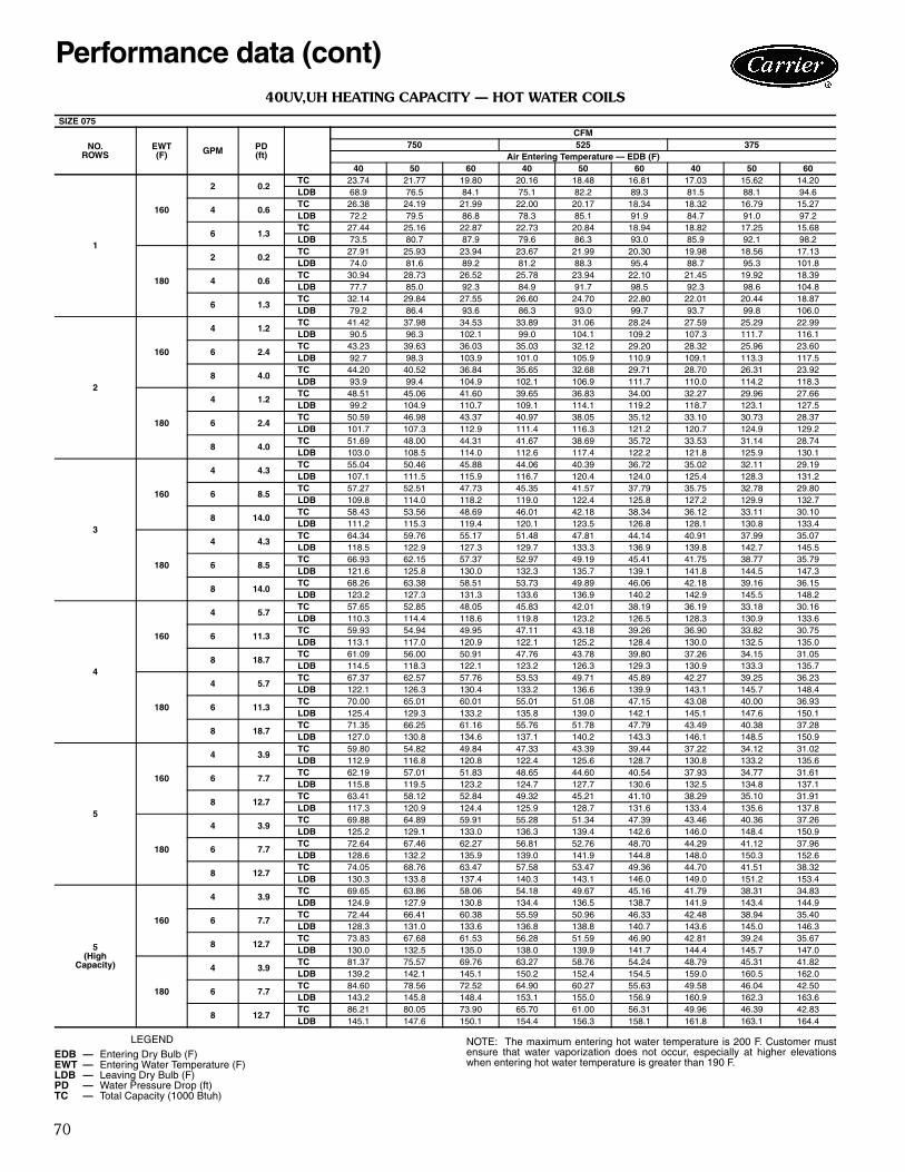
70
40UV,UH HEATING CAPACITY — HOT WATER COILS
LEGEND
SIZE 075
NO. ROWS
EWT(F) GPM PD
(ft)
CFM750 525 375
Air Entering Temperature — EDB (F)40 50 60 40 50 60 40 50 60
1
160
2 0.2TC 23.74 21.77 19.80 20.16 18.48 16.81 17.03 15.62 14.20LDB 68.9 76.5 84.1 75.1 82.2 89.3 81.5 88.1 94.6
4 0.6TC 26.38 24.19 21.99 22.00 20.17 18.34 18.32 16.79 15.27LDB 72.2 79.5 86.8 78.3 85.1 91.9 84.7 91.0 97.2
6 1.3TC 27.44 25.16 22.87 22.73 20.84 18.94 18.82 17.25 15.68LDB 73.5 80.7 87.9 79.6 86.3 93.0 85.9 92.1 98.2
180
2 0.2TC 27.91 25.93 23.94 23.67 21.99 20.30 19.98 18.56 17.13LDB 74.0 81.6 89.2 81.2 88.3 95.4 88.7 95.3 101.8
4 0.6TC 30.94 28.73 26.52 25.78 23.94 22.10 21.45 19.92 18.39LDB 77.7 85.0 92.3 84.9 91.7 98.5 92.3 98.6 104.8
6 1.3TC 32.14 29.84 27.55 26.60 24.70 22.80 22.01 20.44 18.87LDB 79.2 86.4 93.6 86.3 93.0 99.7 93.7 99.8 106.0
2
160
4 1.2TC 41.42 37.98 34.53 33.89 31.06 28.24 27.59 25.29 22.99LDB 90.5 96.3 102.1 99.0 104.1 109.2 107.3 111.7 116.1
6 2.4TC 43.23 39.63 36.03 35.03 32.12 29.20 28.32 25.96 23.60LDB 92.7 98.3 103.9 101.0 105.9 110.9 109.1 113.3 117.5
8 4.0TC 44.20 40.52 36.84 35.65 32.68 29.71 28.70 26.31 23.92LDB 93.9 99.4 104.9 102.1 106.9 111.7 110.0 114.2 118.3
180
4 1.2TC 48.51 45.06 41.60 39.65 36.83 34.00 32.27 29.96 27.66LDB 99.2 104.9 110.7 109.1 114.1 119.2 118.7 123.1 127.5
6 2.4TC 50.59 46.98 43.37 40.97 38.05 35.12 33.10 30.73 28.37LDB 101.7 107.3 112.9 111.4 116.3 121.2 120.7 124.9 129.2
8 4.0TC 51.69 48.00 44.31 41.67 38.69 35.72 33.53 31.14 28.74LDB 103.0 108.5 114.0 112.6 117.4 122.2 121.8 125.9 130.1
3
160
4 4.3TC 55.04 50.46 45.88 44.06 40.39 36.72 35.02 32.11 29.19LDB 107.1 111.5 115.9 116.7 120.4 124.0 125.4 128.3 131.2
6 8.5TC 57.27 52.51 47.73 45.35 41.57 37.79 35.75 32.78 29.80LDB 109.8 114.0 118.2 119.0 122.4 125.8 127.2 129.9 132.7
8 14.0TC 58.43 53.56 48.69 46.01 42.18 38.34 36.12 33.11 30.10LDB 111.2 115.3 119.4 120.1 123.5 126.8 128.1 130.8 133.4
180
4 4.3TC 64.34 59.76 55.17 51.48 47.81 44.14 40.91 37.99 35.07LDB 118.5 122.9 127.3 129.7 133.3 136.9 139.8 142.7 145.5
6 8.5TC 66.93 62.15 57.37 52.97 49.19 45.41 41.75 38.77 35.79LDB 121.6 125.8 130.0 132.3 135.7 139.1 141.8 144.5 147.3
8 14.0TC 68.26 63.38 58.51 53.73 49.89 46.06 42.18 39.16 36.15LDB 123.2 127.3 131.3 133.6 136.9 140.2 142.9 145.5 148.2
4
160
4 5.7TC 57.65 52.85 48.05 45.83 42.01 38.19 36.19 33.18 30.16LDB 110.3 114.4 118.6 119.8 123.2 126.5 128.3 130.9 133.6
6 11.3TC 59.93 54.94 49.95 47.11 43.18 39.26 36.90 33.82 30.75LDB 113.1 117.0 120.9 122.1 125.2 128.4 130.0 132.5 135.0
8 18.7TC 61.09 56.00 50.91 47.76 43.78 39.80 37.26 34.15 31.05LDB 114.5 118.3 122.1 123.2 126.3 129.3 130.9 133.3 135.7
180
4 5.7TC 67.37 62.57 57.76 53.53 49.71 45.89 42.27 39.25 36.23LDB 122.1 126.3 130.4 133.2 136.6 139.9 143.1 145.7 148.4
6 11.3TC 70.00 65.01 60.01 55.01 51.08 47.15 43.08 40.00 36.93LDB 125.4 129.3 133.2 135.8 139.0 142.1 145.1 147.6 150.1
8 18.7TC 71.35 66.25 61.16 55.76 51.78 47.79 43.49 40.38 37.28LDB 127.0 130.8 134.6 137.1 140.2 143.3 146.1 148.5 150.9
5
160
4 3.9TC 59.80 54.82 49.84 47.33 43.39 39.44 37.22 34.12 31.02LDB 112.9 116.8 120.8 122.4 125.6 128.7 130.8 133.2 135.6
6 7.7TC 62.19 57.01 51.83 48.65 44.60 40.54 37.93 34.77 31.61LDB 115.8 119.5 123.2 124.7 127.7 130.6 132.5 134.8 137.1
8 12.7TC 63.41 58.12 52.84 49.32 45.21 41.10 38.29 35.10 31.91LDB 117.3 120.9 124.4 125.9 128.7 131.6 133.4 135.6 137.8
180
4 3.9TC 69.88 64.89 59.91 55.28 51.34 47.39 43.46 40.36 37.26LDB 125.2 129.1 133.0 136.3 139.4 142.6 146.0 148.4 150.9
6 7.7TC 72.64 67.46 62.27 56.81 52.76 48.70 44.29 41.12 37.96LDB 128.6 132.2 135.9 139.0 141.9 144.8 148.0 150.3 152.6
8 12.7TC 74.05 68.76 63.47 57.58 53.47 49.36 44.70 41.51 38.32LDB 130.3 133.8 137.4 140.3 143.1 146.0 149.0 151.2 153.4
5 (High
Capacity)
160
4 3.9TC 69.65 63.86 58.06 54.18 49.67 45.16 41.79 38.31 34.83LDB 124.9 127.9 130.8 134.4 136.5 138.7 141.9 143.4 144.9
6 7.7TC 72.44 66.41 60.38 55.59 50.96 46.33 42.48 38.94 35.40LDB 128.3 131.0 133.6 136.8 138.8 140.7 143.6 145.0 146.3
8 12.7TC 73.83 67.68 61.53 56.28 51.59 46.90 42.81 39.24 35.67LDB 130.0 132.5 135.0 138.0 139.9 141.7 144.4 145.7 147.0
180
4 3.9TC 81.37 75.57 69.76 63.27 58.76 54.24 48.79 45.31 41.82LDB 139.2 142.1 145.1 150.2 152.4 154.5 159.0 160.5 162.0
6 7.7TC 84.60 78.56 72.52 64.90 60.27 55.63 49.58 46.04 42.50LDB 143.2 145.8 148.4 153.1 155.0 156.9 160.9 162.3 163.6
8 12.7TC 86.21 80.05 73.90 65.70 61.00 56.31 49.96 46.39 42.83LDB 145.1 147.6 150.1 154.4 156.3 158.1 161.8 163.1 164.4
EDB — Entering Dry Bulb (F)EWT — Entering Water Temperature (F)LDB — Leaving Dry Bulb (F)PD — Water Pressure Drop (ft)TC — Total Capacity (1000 Btuh)
Performance data (cont)
NOTE: The maximum entering hot water temperature is 200 F. Customer mustensure that water vaporization does not occur, especially at higher elevationswhen entering hot water temperature is greater than 190 F.

71
40UV,UH HEATING CAPACITY — HOT WATER COILS (cont)
LEGEND
SIZE 100
NO. ROWS
EWT(F) GPM PD
(ft)
CFM1000 700 500
Air Entering Temperature — EDB (F)40 50 60 40 50 60 40 50 60
1
160
2 0.2TC 30.53 28.00 25.46 26.07 23.91 21.74 22.15 20.31 18.47LDB 67.9 75.6 83.3 74.1 81.2 88.4 80.5 87.1 93.8
4 0.8TC 34.52 31.65 28.77 28.88 26.48 24.07 24.11 22.10 20.10LDB 71.6 78.9 86.3 77.7 84.6 91.5 84.1 90.4 96.8
6 1.6TC 36.12 33.11 30.10 29.99 27.49 24.99 24.87 22.80 20.73LDB 73.0 80.3 87.5 79.2 85.9 92.6 85.5 91.7 97.9
180
2 0.2TC 35.87 33.33 30.78 30.61 28.43 26.25 25.98 24.13 22.28LDB 72.8 80.5 88.2 80.0 87.1 94.3 87.5 94.1 100.7
4 0.8TC 40.47 37.59 34.70 33.84 31.43 29.01 28.23 26.21 24.20LDB 77.0 84.4 91.7 84.2 91.1 97.9 91.6 97.9 104.3
6 1.6TC 42.29 39.27 36.26 35.09 32.59 30.08 29.09 27.01 24.94LDB 78.7 85.9 93.2 85.8 92.6 99.3 93.2 99.4 105.6
2
160
4 1.5TC 53.75 49.28 44.82 44.24 40.56 36.88 36.20 33.18 30.17LDB 89.2 95.1 101.0 97.8 103.0 108.2 106.2 110.7 115.2
6 3.0TC 56.62 51.90 47.19 46.07 42.23 38.40 37.36 34.24 31.13LDB 91.8 97.5 103.2 100.2 105.2 110.2 108.3 112.6 116.9
8 4.9TC 58.15 53.30 48.46 47.04 43.12 39.20 37.96 34.80 31.64LDB 93.2 98.7 104.3 101.5 106.3 111.2 109.4 113.7 117.9
180
4 1.5TC 62.94 58.46 53.97 51.77 48.08 44.39 42.33 39.31 36.29LDB 97.6 103.5 109.4 107.6 112.8 118.0 117.4 121.9 126.4
6 3.0TC 66.24 61.52 56.79 53.88 50.03 46.18 43.66 40.54 37.43LDB 100.6 106.3 111.9 110.4 115.4 120.3 119.9 124.2 128.5
8 4.9TC 68.01 63.15 58.29 54.98 51.06 47.13 44.36 41.19 38.02LDB 102.2 107.7 113.3 111.8 116.7 121.6 121.1 125.3 129.5
3
160
4 5.4TC 65.76 60.29 54.82 53.25 48.82 44.39 42.83 39.26 35.70LDB 100.1 105.1 110.1 109.6 113.8 118.0 118.3 121.8 125.3
6 10.7TC 69.00 63.25 57.51 55.19 50.59 45.99 43.96 40.29 36.63LDB 103.1 107.8 112.6 112.1 116.1 120.1 120.4 123.7 127.0
8 17.7TC 70.68 64.79 58.90 56.17 51.49 46.81 44.53 40.82 37.11LDB 104.6 109.3 113.9 113.4 117.3 121.2 121.4 124.7 127.9
180
4 5.4TC 76.87 71.38 65.90 62.22 57.79 53.35 50.03 46.46 42.89LDB 110.3 115.3 120.3 121.3 125.5 129.7 131.5 135.0 138.4
6 10.7TC 80.61 74.86 69.11 64.46 59.86 55.25 51.33 47.67 44.00LDB 113.7 118.5 123.2 124.2 128.2 132.2 133.9 137.2 140.5
8 17.7TC 82.56 76.66 70.77 65.60 60.91 56.23 51.99 48.28 44.56LDB 115.5 120.1 124.7 125.7 129.6 133.5 135.1 138.3 141.5
4
160
4 7.3TC 74.86 68.63 62.40 60.05 55.05 50.05 47.74 43.77 39.79LDB 108.5 112.8 117.1 118.5 121.9 125.4 127.3 130.1 132.8
6 14.4TC 78.73 72.17 65.62 62.25 57.07 51.88 48.96 44.88 40.80LDB 112.0 116.0 120.0 121.3 124.6 127.8 129.5 132.1 134.6
8 23.7TC 80.72 74.00 67.27 63.36 58.08 52.80 49.57 45.44 41.31LDB 113.8 117.7 121.5 122.8 125.9 129.0 130.7 133.1 135.6
180
4 7.3TC 87.48 81.24 75.00 70.15 65.14 60.14 55.75 51.77 47.79LDB 120.0 124.3 128.6 131.6 135.1 138.6 142.0 144.7 147.4
6 14.4TC 91.97 85.40 78.84 72.69 67.51 62.32 57.16 53.08 49.00LDB 124.1 128.1 132.1 135.0 138.2 141.4 144.5 147.1 149.6
8 23.7TC 94.26 87.54 80.81 73.98 68.70 63.41 57.86 53.73 49.60LDB 126.2 130.1 133.9 136.6 139.7 142.8 145.8 148.3 150.7
5
160
4 4.9TC 83.65 76.69 69.73 66.50 60.96 55.43 52.25 47.90 43.55LDB 116.5 120.1 123.8 126.9 129.6 132.4 135.6 137.6 139.6
6 9.8TC 88.24 80.90 73.55 68.97 63.22 57.48 53.53 49.07 44.61LDB 120.7 124.0 127.3 130.1 132.6 135.1 137.9 139.8 141.6
8 16.1TC 90.57 83.03 75.48 70.19 64.34 58.49 54.15 49.64 45.13LDB 122.8 125.9 129.0 131.7 134.1 136.4 139.0 140.8 142.5
180
4 4.9TC 97.76 90.79 83.82 77.68 72.14 66.60 61.02 56.66 52.31LDB 129.4 133.0 136.7 141.5 144.2 147.0 151.6 153.6 155.7
6 9.8TC 103.08 95.73 88.37 80.54 74.79 69.04 62.49 58.03 53.57LDB 134.3 137.5 140.8 145.2 147.7 150.2 154.3 156.1 158.0
8 16.1TC 105.77 98.22 90.67 81.95 76.10 70.25 63.22 58.70 54.19LDB 136.7 139.8 142.9 147.1 149.4 151.8 155.6 157.4 159.1
5 (High
Capacity)
160
4 4.9TC 95.85 87.89 79.91 74.92 68.68 62.44 57.70 52.90 48.09LDB 127.7 130.4 133.1 137.9 139.7 141.6 145.5 146.8 148.0
6 9.8TC 101.10 92.69 84.27 77.44 70.99 64.54 58.85 53.95 49.05LDB 132.5 134.8 137.1 141.2 142.7 144.3 147.6 148.7 149.7
8 16.1TC 103.65 95.02 86.38 78.64 72.09 65.54 59.39 54.44 49.49LDB 134.8 136.9 139.0 142.7 144.2 145.6 148.6 149.6 150.5
180
4 4.9TC 111.99 104.00 96.02 87.49 81.25 75.01 67.37 62.56 57.75LDB 142.4 145.1 147.8 154.3 156.1 158.0 163.2 164.4 165.6
6 9.8TC 118.07 109.65 101.22 90.41 83.96 77.50 68.69 63.79 58.88LDB 148.0 150.3 152.6 158.1 159.7 161.2 165.6 166.7 167.7
8 16.1TC 121.02 112.38 103.74 91.80 85.24 78.68 69.31 64.36 59.41LDB 150.7 152.8 154.9 159.9 161.4 162.8 166.8 167.7 168.7
EDB — Entering Dry Bulb (F)EWT — Entering Water Temperature (F)LDB — Leaving Dry Bulb (F)PD — Water Pressure Drop (ft)TC — Total Capacity (1000 Btuh)
NOTE: The maximum entering hot water temperature is 200 F. Customer mustensure that water vaporization does not occur, especially at higher elevations whenentering hot water temperature is greater than 190 F.

72
40UV,UH HEATING CAPACITY — HOT WATER COILS (cont)
LEGEND
SIZE 125
NO. ROWS
EWT(F) GPM PD
(ft)
CFM1250 875 625
Air Entering Temperature — EDB (F)40 50 60 40 50 60 40 50 60
1
160
2 0.3TC 36.78 33.74 30.70 31.60 28.98 26.36 26.98 24.74 22.50LDB 66.9 74.7 82.5 73.0 80.3 87.5 79.5 86.2 92.9
4 0.9TC 42.30 38.78 35.27 35.52 32.56 29.60 29.73 27.25 24.78LDB 70.9 78.4 85.8 77.1 84.0 90.9 83.5 89.9 96.3
6 1.9TC 44.53 40.82 37.11 37.05 33.97 30.88 30.79 28.23 25.66LDB 72.6 79.9 87.2 78.7 85.5 92.3 85.1 91.3 97.6
180
2 0.3TC 43.22 40.16 37.09 37.09 34.46 31.82 31.64 29.39 27.13LDB 71.6 79.4 87.1 78.8 86.0 93.3 86.3 93.0 99.7
4 0.9TC 49.58 46.06 42.52 41.60 38.63 35.67 34.81 32.32 29.84LDB 76.3 83.7 91.1 83.5 90.4 97.3 90.9 97.3 103.7
6 1.9TC 52.15 48.43 44.70 43.36 40.27 37.17 36.01 33.44 30.87LDB 78.2 85.4 92.7 85.3 92.1 98.8 92.7 98.9 105.2
2
160
4 1.8TC 65.33 59.91 54.48 54.09 49.60 45.10 44.48 40.78 37.08LDB 87.8 93.8 99.9 96.5 101.8 107.1 105.1 109.7 114.3
6 3.6TC 69.44 63.66 57.88 56.75 52.02 47.30 46.16 42.32 38.47LDB 90.8 96.6 102.3 99.3 104.4 109.4 107.5 111.9 116.3
8 5.9TC 71.65 65.69 59.71 58.14 53.30 48.46 47.04 43.13 39.21LDB 92.4 98.1 103.7 100.8 105.7 110.6 108.8 113.1 117.4
180
4 1.8TC 76.50 71.05 65.60 63.30 58.79 54.28 52.02 48.31 44.60LDB 96.0 102.0 108.0 106.2 111.4 116.7 116.1 120.7 125.3
6 3.6TC 81.24 75.44 69.65 66.35 61.62 56.89 53.96 50.11 46.25LDB 99.4 105.2 111.0 109.3 114.4 119.5 119.0 123.3 127.7
8 5.9TC 83.78 77.80 71.83 67.97 63.11 58.26 54.97 51.04 47.12LDB 101.3 106.9 112.5 111.0 116.0 120.9 120.4 124.7 128.9
3
160
6 7.2TC 87.16 79.90 72.65 70.06 64.23 58.39 55.96 51.29 46.63LDB 103.8 108.5 113.1 113.2 117.1 121.0 121.9 125.1 128.2
8 11.9TC 89.89 82.40 74.92 71.66 65.69 59.72 56.88 52.14 47.40LDB 105.8 110.3 114.8 114.9 118.7 122.4 123.2 126.3 129.4
10 17.6TC 91.57 83.95 76.31 72.64 66.58 60.53 57.43 52.65 47.86LDB 107.0 111.4 115.8 115.9 119.6 123.3 124.0 127.0 130.0
180
6 7.2TC 101.86 94.60 87.33 81.85 76.01 70.16 65.35 60.69 56.02LDB 114.5 119.2 123.9 125.5 129.4 133.3 135.6 138.8 142.0
8 11.9TC 105.02 97.52 90.03 83.70 77.72 71.75 66.42 61.67 56.93LDB 116.8 121.3 125.9 127.5 131.2 135.0 137.2 140.2 143.3
10 17.6TC 106.96 99.33 91.69 84.83 78.77 72.71 67.05 62.27 57.48LDB 118.3 122.7 127.1 128.7 132.3 136.0 138.1 141.1 144.1
4
160
8 9.5TC 98.72 90.51 82.28 77.97 71.48 64.98 61.28 56.17 51.07LDB 112.2 116.2 120.2 121.5 124.7 127.9 129.7 132.2 134.7
10 14.1TC 100.63 92.25 83.87 79.04 72.45 65.87 61.86 56.70 51.55LDB 113.6 117.5 121.4 122.6 125.7 128.8 130.5 133.0 135.4
12 19.6TC 101.92 93.43 84.93 79.75 73.11 66.46 62.25 57.06 51.88LDB 114.6 118.3 122.1 123.3 126.4 129.5 131.1 133.5 135.9
180
8 9.5TC 115.34 107.10 98.87 91.06 84.56 78.06 71.55 66.44 61.33LDB 124.4 128.4 132.3 135.2 138.4 141.6 144.7 147.2 149.7
10 14.1TC 117.53 109.15 100.75 92.29 85.70 79.11 72.22 67.06 61.90LDB 126.0 129.9 133.7 136.5 139.6 142.7 145.7 148.1 150.6
12 19.6TC 119.02 110.52 102.03 93.11 86.46 79.81 72.67 67.48 62.29LDB 127.1 130.9 134.6 137.3 140.4 143.4 146.3 148.7 151.1
5
160
8 5.5TC 106.55 97.68 88.81 83.47 76.51 69.56 65.02 59.60 54.18LDB 117.9 121.5 125.0 127.2 130.0 132.7 135.1 137.2 139.3
10 8.2TC 108.68 99.63 90.58 84.62 77.57 70.52 65.62 60.15 54.68LDB 119.5 122.9 126.3 128.4 131.1 133.7 136.0 138.0 140.0
12 11.5TC 110.12 100.95 91.77 85.38 78.27 71.15 66.02 60.52 55.02LDB 120.6 123.9 127.1 129.2 131.8 134.4 136.6 138.6 140.5
180
8 5.5TC 124.48 115.60 106.72 97.48 90.52 83.56 75.91 70.49 65.07LDB 131.1 134.6 138.1 141.9 144.6 147.3 151.1 153.1 155.2
10 8.2TC 126.95 117.89 108.83 98.81 91.75 84.70 76.61 71.13 65.66LDB 132.9 136.2 139.6 143.3 145.9 148.5 152.1 154.1 156.1
12 11.5TC 128.61 119.42 110.24 99.69 92.57 85.45 77.07 71.56 66.06LDB 134.1 137.4 140.7 144.2 146.8 149.3 152.8 154.7 156.7
5 (High
Capacity)
160
8 5.5TC 123.05 112.81 102.56 94.54 86.66 78.79 72.14 66.13 60.11LDB 130.0 132.5 135.0 138.8 140.6 142.3 145.5 146.8 148.0
10 8.2TC 125.44 115.00 104.55 95.70 87.73 79.75 72.68 66.62 60.57LDB 131.8 134.1 136.5 140.0 141.7 143.4 146.3 147.5 148.6
12 11.5TC 127.03 116.45 105.86 96.46 88.42 80.38 73.03 66.95 60.86LDB 132.9 135.2 137.5 140.8 142.4 144.0 146.9 148.0 149.1
180
8 5.5TC 143.72 133.47 123.21 110.38 102.50 94.62 84.21 78.19 72.18LDB 145.1 147.6 150.1 155.4 157.1 158.9 163.2 164.4 165.6
10 8.2TC 146.49 136.04 125.58 111.72 103.75 95.77 84.83 78.77 72.71LDB 147.2 149.5 151.9 156.8 158.4 160.1 164.1 165.3 166.4
12 11.5TC 148.32 137.73 127.14 112.60 104.56 96.52 85.24 79.15 73.06LDB 148.5 150.8 153.0 157.7 159.3 160.9 164.7 165.8 166.9
EDB — Entering Dry Bulb (F)EWT — Entering Water Temperature (F)LDB — Leaving Dry Bulb (F)PD — Water Pressure Drop (ft)TC — Total Capacity (1000 Btuh)
Performance data (cont)
NOTE: The maximum entering hot water temperature is 200 F. Customer mustensure that water vaporization does not occur, especially at higher elevationswhen entering hot water temperature is greater than 190 F.

73
40UV,UH HEATING CAPACITY — HOT WATER COILS (cont)
LEGEND NOTE: The maximum entering hot water temperature is 200 F. Customer mustensure that water vaporization does not occur, especially at higher elevationswhen entering hot water temperature is greater than 190 F.
SIZE 150
NO. ROWS
EWT(F) GPM PD
(ft)
CFM1500 1050 750
Air Entering Temperature — EDB (F)40 50 60 40 50 60 40 50 60
1
160
2 0.3TC 43.12 39.55 35.98 37.25 34.17 31.08 31.95 29.30 26.65LDB 66.3 74.1 81.9 72.4 79.8 87.1 79.0 85.7 92.5
4 1.1TC 50.50 46.31 42.11 42.53 38.99 35.46 35.69 32.72 29.74LDB 70.8 78.2 85.7 77.0 84.0 90.9 83.5 89.9 96.3
6 2.2TC 53.55 49.09 44.63 44.63 40.91 37.20 37.13 34.04 30.95LDB 72.6 79.9 87.2 78.9 85.6 92.4 85.3 91.5 97.7
180
2 0.3TC 50.64 47.07 43.47 43.72 40.62 37.51 37.46 34.80 32.13LDB 70.9 78.7 86.5 78.1 85.4 92.7 85.7 92.4 99.2
4 1.1TC 59.20 54.98 50.77 49.82 46.26 42.72 41.77 38.79 35.81LDB 76.1 83.5 91.0 83.4 90.3 97.2 90.9 97.3 103.7
6 2.2TC 62.70 58.22 53.75 52.24 48.51 44.78 43.43 40.33 37.23LDB 78.2 85.5 92.8 85.5 92.2 99.0 93.0 99.2 105.4
2
160
4 2.1TC 77.57 71.13 64.68 64.57 59.21 53.84 53.31 48.87 44.44LDB 87.3 93.4 99.4 96.2 101.6 106.9 105.0 109.6 114.2
6 4.2TC 83.29 76.36 69.43 68.29 62.60 56.92 55.67 51.04 46.40LDB 90.8 96.6 102.3 99.5 104.5 109.6 107.9 112.2 116.6
8 6.9TC 86.39 79.20 72.01 70.26 64.41 58.55 56.91 52.16 47.42LDB 92.7 98.3 103.9 101.2 106.1 111.0 109.4 113.6 117.8
180
4 2.1TC 90.82 84.36 77.89 75.56 70.18 64.79 62.34 57.90 53.45LDB 95.4 101.4 107.5 105.8 111.1 116.4 116.0 120.6 125.2
6 4.2TC 97.44 90.50 83.55 79.85 74.15 68.46 65.07 60.43 55.78LDB 99.4 105.2 110.9 109.5 114.6 119.6 119.3 123.7 128.0
8 6.9TC 101.02 93.81 86.61 82.12 76.26 70.40 66.49 61.74 57.00LDB 101.6 107.2 112.8 111.5 116.4 121.3 121.1 125.3 129.5
3
160
6 5.0TC 101.07 92.67 84.26 81.85 75.04 68.22 65.77 60.29 54.82LDB 101.6 106.5 111.4 111.3 115.4 119.4 120.2 123.5 126.8
8 8.3TC 104.85 96.13 87.40 84.10 77.09 70.09 67.08 61.49 55.90LDB 103.9 108.6 113.3 113.2 117.1 121.0 121.8 125.0 128.2
10 12.3TC 107.19 98.27 89.34 85.47 78.35 71.23 67.87 62.21 56.56LDB 105.4 109.9 114.5 114.4 118.2 122.0 122.8 125.9 129.0
180
6 5.0TC 118.15 109.73 101.30 95.64 88.82 81.99 76.83 71.34 65.86LDB 112.0 116.9 121.8 123.3 127.4 131.4 133.7 137.0 140.3
8 8.3TC 122.53 113.79 105.04 98.24 91.23 84.21 78.34 72.74 67.15LDB 114.7 119.4 124.0 125.6 129.5 133.3 135.5 138.7 141.9
10 12.3TC 125.23 116.29 107.36 99.82 92.70 85.57 79.25 73.59 67.93LDB 116.3 120.9 125.5 126.9 130.7 134.5 136.6 139.7 142.8
4
160
8 7.4TC 121.13 111.05 100.96 95.96 87.97 79.98 75.46 69.18 62.89LDB 113.8 117.7 121.6 123.6 126.6 129.7 132.0 134.3 136.7
10 11.0TC 124.00 113.68 103.35 97.56 89.43 81.31 76.32 69.96 63.60LDB 115.6 119.3 123.0 125.0 127.9 130.8 133.1 135.3 137.6
12 15.2TC 125.95 115.46 104.97 98.63 90.41 82.19 76.89 70.48 64.08LDB 116.8 120.4 124.0 125.9 128.7 131.6 133.8 135.9 138.1
180
8 7.4TC 141.53 131.44 121.34 112.09 104.09 96.09 88.12 81.83 75.53LDB 126.3 130.1 134.0 137.6 140.7 143.7 147.4 149.8 152.1
10 11.0TC 144.86 134.53 124.19 113.93 105.80 97.66 89.11 82.74 76.38LDB 128.3 132.0 135.7 139.2 142.1 145.1 148.7 150.9 153.1
12 15.2TC 147.11 136.61 126.11 115.16 106.94 98.72 89.76 83.35 76.94LDB 129.7 133.3 136.9 140.3 143.1 146.0 149.5 151.6 153.8
5
160
8 6.5TC 129.85 119.05 108.24 102.04 93.54 85.04 79.53 72.90 66.28LDB 119.2 122.6 126.0 128.9 131.5 134.1 137.0 138.9 140.8
10 9.6TC 132.98 121.91 110.84 103.70 95.06 86.43 80.39 73.69 66.99LDB 121.1 124.3 127.6 130.3 132.8 135.3 138.0 139.9 141.7
12 13.4TC 135.08 123.83 112.58 104.81 96.08 87.34 80.95 74.21 67.46LDB 122.4 125.5 128.6 131.3 133.7 136.1 138.7 140.5 142.3
180
8 6.5TC 151.72 140.90 130.07 119.18 110.67 102.16 92.86 86.23 79.60LDB 132.5 135.9 139.3 143.8 146.4 149.0 153.2 155.1 157.1
10 9.6TC 155.33 144.25 133.17 121.10 112.45 103.81 93.85 87.15 80.44LDB 134.7 137.9 141.2 145.5 147.9 150.4 154.4 156.3 158.1
12 13.4TC 157.76 146.50 135.24 122.37 113.64 104.90 94.50 87.75 81.00LDB 136.2 139.3 142.5 146.6 149.0 151.4 155.2 157.0 158.8
5 (High
Capacity)
160
8 6.5TC 148.99 136.59 124.19 114.83 105.26 95.70 87.64 80.34 73.04LDB 130.8 133.3 135.7 140.0 141.7 143.3 146.9 148.0 149.1
10 9.6TC 152.49 139.79 127.09 116.49 106.78 97.08 88.39 81.03 73.66LDB 133.0 135.2 137.5 141.5 143.0 144.6 147.8 148.8 149.8
12 13.4TC 154.78 141.89 129.00 117.57 107.77 97.98 88.88 81.47 74.07LDB 134.4 136.5 138.6 142.4 143.9 145.3 148.4 149.3 150.3
180
8 6.5TC 174.03 161.61 149.20 134.07 124.50 114.93 102.30 95.00 87.69LDB 146.1 148.5 151.0 156.8 158.4 160.1 164.7 165.8 166.9
10 9.6TC 178.07 165.36 152.66 135.99 126.28 116.57 103.17 95.80 88.44LDB 148.6 150.8 153.1 158.4 160.0 161.5 165.8 166.8 167.8
12 13.4TC 180.73 167.83 154.92 137.24 127.44 117.64 103.73 96.33 88.92LDB 150.2 152.3 154.5 159.5 161.0 162.5 166.5 167.5 168.4
EDB — Entering Dry Bulb (F)EWT — Entering Water Temperature (F)LDB — Leaving Dry Bulb (F)PD — Water Pressure Drop (ft)TC — Total Capacity (1000 Btuh)

74
40UH HEATING CAPACITY — HOT WATER COILS
LEGEND NOTE: The maximum entering hot water temperature is 200 F. Customer mustensure that water vaporization does not occur, especially at higher elevationswhen entering hot water temperature is greater than 190 F.
SIZE 200
NO. ROWS
EWT(F) GPM PD
(ft)
CFM2000 1400 1000
Air Entering Temperature — EDB (F)40 50 60 40 50 60 40 50 60
1
160
2 0.3TC 58.20 53.41 48.60 51.11 46.90 42.66 44.41 40.73 37.05LDB 66.6 74.4 82.2 73.4 80.6 87.9 80.6 87.3 93.9
4 1.1TC 71.75 65.80 59.85 61.00 55.93 50.86 51.50 47.22 42.94LDB 72.8 80.1 87.4 79.8 86.5 93.2 87.1 93.2 99.3
6 2.2TC 77.62 71.17 64.72 65.10 59.68 54.27 54.35 49.83 45.30LDB 75.5 82.5 89.6 82.5 89.0 95.4 89.7 95.6 101.4
180
2 0.3TC 68.35 63.53 58.69 59.97 55.73 51.48 52.07 48.38 44.68LDB 71.3 79.0 86.8 79.2 86.4 93.6 87.6 94.2 100.9
4 1.1TC 84.12 78.14 72.16 71.45 66.36 61.28 60.29 56.00 51.70LDB 78.5 85.7 93.0 86.7 93.3 100.0 95.1 101.2 107.3
6 2.2TC 90.90 84.43 77.95 76.19 70.76 65.33 63.58 59.04 54.51LDB 81.6 88.6 95.6 89.8 96.2 102.7 98.1 104.0 109.8
2
160
4 2.1TC 106.48 97.65 88.83 89.86 82.40 74.94 74.83 68.61 62.38LDB 88.7 94.7 100.6 98.7 103.8 108.9 108.4 112.7 117.0
6 4.2TC 117.40 107.64 97.89 96.99 88.93 80.86 79.36 72.76 66.15LDB 93.7 99.2 104.8 103.4 108.1 112.8 112.6 116.5 120.5
8 6.9TC 123.44 113.17 102.90 100.82 92.43 84.04 81.74 74.93 68.13LDB 96.4 101.7 107.0 105.9 110.4 114.9 114.7 118.5 122.3
180
4 2.1TC 124.67 115.81 106.95 105.15 97.67 90.19 87.51 81.28 75.04LDB 97.0 103.0 108.9 108.7 113.8 118.9 120.0 124.3 128.6
6 4.2TC 137.36 127.58 117.79 113.42 105.34 97.25 92.76 86.15 79.53LDB 102.8 108.3 113.9 114.1 118.8 123.5 124.8 128.8 132.7
8 6.9TC 144.35 134.06 123.77 117.86 109.45 101.04 95.51 88.69 81.87LDB 106.0 111.3 116.6 117.0 121.5 126.0 127.3 131.1 134.9
3
160
6 5.0TC 139.03 127.47 115.91 113.55 104.11 94.66 91.59 83.97 76.34LDB 103.6 108.3 113.0 114.2 118.0 121.8 123.8 126.8 129.8
8 8.3TC 146.21 134.05 121.88 117.79 107.98 98.17 94.00 86.17 78.34LDB 106.9 111.3 115.7 116.9 120.5 124.1 126.0 128.8 131.6
10 12.3TC 150.67 138.13 125.58 120.36 110.34 100.31 95.45 87.50 79.54LDB 108.9 113.2 117.4 118.6 122.1 125.5 127.3 130.0 132.7
180
6 5.0TC 162.52 150.94 139.37 132.69 123.23 113.76 106.99 99.35 91.72LDB 114.3 119.0 123.7 126.7 130.5 134.3 137.8 140.9 143.9
8 8.3TC 170.86 158.68 146.49 137.59 127.78 117.96 109.78 101.94 94.10LDB 118.1 122.6 127.0 129.9 133.5 137.1 140.4 143.2 146.1
10 12.3TC 176.02 163.46 150.91 140.58 130.54 120.51 111.45 103.49 95.53LDB 120.5 124.7 129.0 131.8 135.3 138.7 141.9 144.6 147.4
4
160
8 7.4TC 168.88 154.83 140.78 134.36 123.18 111.99 105.56 96.77 87.98LDB 117.2 120.8 124.4 127.8 130.5 133.2 136.5 138.5 140.5
10 11.0TC 174.38 159.86 145.35 137.32 125.88 114.45 107.09 98.17 89.25LDB 119.7 123.1 126.5 129.7 132.2 134.8 137.9 139.8 141.6
12 15.2TC 178.08 163.25 148.42 139.28 127.68 116.08 108.09 99.08 90.08LDB 121.4 124.6 127.9 131.0 133.4 135.8 138.8 140.6 142.4
180
8 7.4TC 197.33 183.27 169.20 156.94 145.74 134.54 123.26 114.46 105.66LDB 130.2 133.8 137.4 142.5 145.2 147.9 152.7 154.7 156.6
10 11.0TC 203.72 189.18 174.65 160.37 148.92 137.47 125.02 116.10 107.17LDB 133.1 136.5 139.9 144.8 147.3 149.8 154.3 156.2 158.0
12 15.2TC 208.00 193.15 178.31 162.63 151.02 139.41 126.18 117.17 108.16LDB 135.1 138.3 141.5 146.2 148.7 151.1 155.4 157.2 158.9
5 (High
Capacity)
160
8 6.5TC 185.94 170.47 155.00 146.24 134.06 121.89 113.31 103.88 94.44LDB 125.0 127.9 130.9 135.5 137.6 139.6 143.6 145.0 146.4
10 9.6TC 192.12 176.13 160.14 149.33 136.90 124.46 114.78 105.21 95.65LDB 127.8 130.5 133.2 137.5 139.4 141.3 145.0 146.2 147.5
12 13.4TC 196.22 179.89 163.55 151.34 138.74 126.13 115.71 106.08 96.43LDB 129.7 132.3 134.8 138.9 140.6 142.4 145.8 147.0 148.2
180
8 6.5TC 217.25 201.76 186.28 170.80 158.61 146.43 132.30 122.86 113.41LDB 139.3 142.3 145.2 151.6 153.6 155.6 161.0 162.4 163.7
10 9.6TC 224.44 208.43 192.42 174.38 161.93 149.49 133.99 124.42 114.86LDB 142.6 145.3 148.0 153.9 155.8 157.6 162.5 163.8 165.0
12 13.4TC 229.18 212.83 196.47 176.71 164.09 151.48 135.07 125.43 115.78LDB 144.8 147.3 149.8 155.4 157.2 158.9 163.5 164.7 165.9
EDB — Entering Dry Bulb (F)EWT — Entering Water Temperature (F)LDB — Leaving Dry Bulb (F)PD — Water Pressure Drop (ft)TC — Total Capacity (1000 Btuh)
Performance data (cont)

75
HEATING CAPACITY — STEAM COILS
LEGEND *40UV only.†40UH only.NOTE: Ratings based on 2 psig steam pressure. See table below forsteam pressure and temperature correction factors. Maximum steampressure is 6 psig at coil inlet.
STEAM CAPACITY CORRECTION FACTORS
NOTE: Standard steam pressure and temperature is 2 psig and 0° F. For all other temperatures andpressures, multiply heating capacity (TTL MBH) as found in 0° F entering air temperature column inHeating Capacity-Steam Coils table by correction factor shown.
UNIT40UV,UH
COILROWS
NOM.AIRFLOW
(cfm)
ENTERING-AIR TEMPERATURE (F db)–20 –10 0 10 20
TTLMBH
LAT(F)
TTLMBH
LAT(F)
TTLMBH
LAT(F)
TTLMBH
LAT(F)
TTLMBH
LAT(F)
050*1 500 49.5 71.0 47.4 77.0 45.3 83.0 43.3 89.0 41.2 96.02 500 69.8 108.0 66.9 113.0 64.0 117.0 61.0 122.0 58.2 127.0
0751 750 67.4 61.0 63.8 67.0 60.2 74.0 56.6 80.0 53.3 87.02 750 107.5 110.0 102.2 114.0 97.0 119.0 91.7 123.0 86.6 128.0
1001 1000 89.8 61.0 85.0 67.0 80.2 74.0 56.6 80.0 53.3 87.02 1000 143.3 110.0 136.3 114.0 129.1 119.0 122.2 123.0 115.4 128.0
1251 1250 112.3 61.0 106.3 67.0 100.3 74.0 94.6 80.0 88.8 87.02 1250 179.0 110.0 170.4 114.0 161.5 119.0 152.6 123.0 144.2 128.0
1501 1500 134.9 61.0 127.7 67.0 120.5 74.0 113.5 80.0 106.6 87.02 1500 214.8 110.0 204.5 114.0 193.7 119.0 183.1 123.0 173.3 128.0
200†1 2000 153.6 51.0 147.1 58.0 140.8 65.0 134.3 72.0 127.6 79.02 2000 248.5 95.0 238.0 110.0 227.9 105.0 217.4 110.0 206.4 115.0
UNIT40UV,UH
COILROWS
NOM.AIRFLOW
(cfm)
ENTERING-AIR TEMPERATURE (F db)30 40 50 60 70
TTLMBH
LAT(F)
TTLMBH
LAT(F)
TTLMBH
LAT(F)
TTLMBH
LAT(F)
TTLMBH
LAT(F)
050*1 500 39.2 102.0 37.0 108.0 35.0 114.0 32.9 120.0 30.9 127.02 500 55.2 132.0 52.3 136.0 49.4 141.0 46.5 145.0 43.6 150.0
0751 750 50.2 94.0 46.8 100.0 43.7 107.0 40.8 113.0 37.7 120.02 750 81.6 132.0 76.8 137.0 71.8 142.0 67.0 146.0 62.4 151.0
1001 1000 66.7 94.0 62.4 100.0 58.3 107.0 54.2 113.0 50.2 120.02 1000 108.7 132.0 102.2 137.0 95.8 142.0 89.3 146.0 83.0 151.0
1251 1250 83.5 94.0 78.0 100.0 73.0 107.0 67.9 113.0 62.6 120.02 1250 135.8 132.0 127.9 137.0 119.8 142.0 111.6 146.0 103.2 151.0
1501 1500 100.3 94.0 93.6 100.0 87.6 107.0 81.6 113.0 75.1 120.02 1500 162.7 132.0 153.6 137.0 143.8 142.0 133.9 146.0 124.8 151.0
200†1 2000 121.5 86.0 115.0 93.0 108.3 100.0 102.0 107.0 95.7 114.02 2000 196.4 121.0 186.0 126.0 175.1 131.0 164.9 136.0 154.7 141.0
db — Dry BulbLAT — Leaving-Air TemperatureTTL MBH — Total Heating, Btuh x 1000
STEAMPRESSURE
(psig)
SATURATEDTEMP
(F)
LATENTHEAT
(Btuh/lb)
ENTERING-AIR TEMPERATURE (F)
–20 –10 0 10 20 30 40 50 60 70
0 212.0 970.3 0.97 0.97 0.97 0.96 0.97 0.97 0.97 0.96 0.96 0.962 218.5 966.2 1.00 1.00 1.00 1.00 1.00 1.00 1.00 1.00 1.00 1.005 227.1 960.6 1.02 1.03 1.03 1.03 1.04 1.05 1.05 1.05 1.05 1.05
LAT =(TTL MBH) x 1000
+ EAT (Entering-Air Temperature)1.082 x Nominal Airflow

76
UNIT VENTILATOR AIRFLOW
PSC MOTOR — SIZE 050-150*
LEGEND
*Standard on sizes 050-150.
NOTE: Use the table below to determine the heating and cooling coil combi-nations available with PSC (Permanent Split Capacitor) Motor operation.
†DX cooling applications are only available in 4-row cooling configuration.
FACTORY SETTINGS — CHILLED WATER COIL APPLICATIONS
Unit SpeedApproximate Air Delivery (CFM)
1-row 2-row 3-row 4-row 5-row 6-row 7-row
40UV050High 522 510 497 485 490 489 457
Medium 503 490 476 464 473 476 444Low 458 449 440 425 452 455 430
40UV,UH075High 806 778 750 747 766 732 697
Medium 682 664 645 629 621 596 570Low 569 554 539 527 533 514 495
40UV,UH100High 1064 1033 1001 1013 973 980 967
Medium 662 659 655 642 763 740 717Low 530 519 507 503 498 501 504
40UV,UH125High 1295 1285 1215 1218 1239 1250 1175
Medium 899 930 876 865 852 846 846Low 568 616 597 570 568 558 573
40UV,UH150High 1542 1480 1500 1484 1468 1482 1374
Medium 1071 1068 1065 1034 1033 1031 1013Low 812 801 790 881 848 842 799
FACTORY SETTINGS — ELECTRIC HEAT/DX COIL APPLICATIONS
Unit SpeedApproximate Air Delivery (CFM)
1-row 2-row 3-row 4-row 5-row 6-row 7-row
40UV050High 522 510 497 485 490 489 457
Medium 503 490 476 464 452 455 430Low 458 449 440 425 410 414 406
40UV,UH075High 806 778 750 747 766 732 697
Medium 682 664 645 629 621 596 570Low 569 554 539 527 533 514 495
40UV,UH100High 1064 1033 1001 1013 973 980 967
Medium 794 788 782 773 857 834 810Low 662 659 655 642 628 620 611
40UV,UH125High 1295 1285 1215 1218 1239 1250 1175
Medium 1055 1040 1024 995 1099 1091 1052Low 738 767 732 719 987 986 964
40UV,UH150High 1542 1480 1500 1484 1468 1482 1374
Medium 1285 1257 1229 1248 1246 1239 1199Low 934 928 922 901 1033 1031 1013
CX — Chilled Water ApplicationsDX — Direct ExpansionHW — Hot Water COOLING COIL
HEATING COILHW Steam Electric
5 Rows CW 1 or 2 rows N/A 3 elements4 Rows CW or DX† 3 rows 1 or 2 rows 4 elements
3 Rows CW 4 rows 1 or 2 rows 5 or 6 elements
Performance data (cont)

77
UNIT VENTILATOR AIRFLOW (cont) ECM — SIZE 050-200
LEGEND * Standard on size 200.
NOTES:1. Factory default is Low Position.2. Med, High, and Max positions are field settings.
SOUND POWER DATASOUND DATA FREE DELIVERY (dB)
NOTES:1. These noise ratings are rated in accordance with AHRI Standard
350.2. Sound power levels were recorded using ANSI S12.32 method.3. All sound ratings are based on 3 row coil except size 200, which is
based on 4 row coil. Sound power is in decibels re 10e-12 w.4. Sound power not relevant for ducted units.
UNIT SIZE MOTORHP COIL TYPE
APPROXIMATE AIR DELIVERY (Cfm)ESP Speed Board Position
Low Position(0.0 in. wg)
Med Position(0.10 in. wg)
High Position(0.25 in. wg)
Max Position(0.45 in. wg)
High Medium Low High Medium Low High Medium Low High Medium Low
40UV050 1/3
CW 499 336 248 — — — — — — — — —3-4EH/DX 499 419 336 — — — — — — — — —
5-6EH 491 380 324 — — — — — — — — —
40UV,UH075 1/3
CW 747 484 346 753 548 432 752 530 427 751 541 3863-4EH/DX 747 644 498 753 609 472 752 612 470 751 618 498
5-6EH 755 645 583 746 598 539 755 585 554 765 610 542
40UV,UH100 1/3
CW 997 703 505 987 693 543 1012 663 483 994 692 4803-4EH/DX 997 853 615 987 850 639 1012 823 626 994 819 618
5-6EH 1016 819 719 1002 851 709 1024 798 787 1024 820 734
40UV,UH125 1/2
CW 1266 880 657 1239 905 609 1235 898 676 1231 898 6273-4EH/DX 1266 1023 769 1239 1055 758 1235 1037 765 1231 1010 778
5-6EH 1259 1049 897 1239 995 888 1226 995 888 1253 994 919
40UV,UH150 1/2
CW 1503 1033 775 1479 1046 712 1494 1020 770 1486 1075 7373-4EH/DX 1503 1246 956 1479 1216 965 1494 1209 927 1486 1222 917
5-6EH 1517 1222 1068 1490 1206 1087 1498 1159 1120 1503 1188 107440UH200* 3/4 ALL 2014 1384 1023 1981 1386 971 1965 1385 997 1814 1354 993
3-4EH/DX — Direct Expansion Coil Applications with 3 to4 Elements of Electric Heat
5-6EH — 5 to 6 Elements of Electric Heat ApplicationsCW — Chilled Water ApplicationsECM — Electronically Commutated MotorESP — External Static Pressure
40UV,UH UNIT SIZE
SWITCH SETTING
ACTUAL CFM
OCTAVE BAND FREQUENCY (Hz)
125 250 500 1000 2000 4000 8000
050High 497 68.0 55.0 52.2 53.0 50.5 44.9 36.9
Medium 476 62.9 54.2 50.6 51.8 49.1 43.3 34.7Low 440 58.9 52.6 48.9 49.9 46.6 40.3 31.2
075High 750 60.0 55.5 57.6 54.5 50.1 45.2 35.6
Medium 645 55.3 51.1 51.1 50.0 44.9 38.0 26.9Low 539 53.8 47.2 46.5 45.4 39.1 30.2 18.7
100High 1001 61.5 55.7 57.2 55.5 50.9 47.3 38.5
Medium 655 53.6 46.5 47.2 44.8 37.5 30.4 21.4Low 507 48.8 41.5 41.0 37.4 27.7 18.3 16.9
125High 1215 67.4 57.4 59.3 56.4 52.1 48.0 38.6
Medium 876 61.7 49.1 49.3 47.5 41.4 34.4 23.9Low 597 51.8 42.7 37.3 32.6 21.7 11.1 16.3
150High 1500 73.9 62.2 67.4 59.8 56.9 53.4 46.3
Medium 1065 62.7 53.0 55.2 51.2 45.4 39.1 28.7Low 790 54.8 48.5 45.5 43.1 34.2 25.3 15.5
200High 1961 78.8 73.4 71.6 68.3 65.9 62.5 55.7
Medium 1340 71.3 66.3 65.0 60.6 56.8 51.4 43.7Low 928 64.2 60.6 60.7 53.0 46.9 39.9 34.8

78
UNITS WITHOUT ELECTRIC HEATMOTOR DATA
LEGEND
*Available in vertical configuration only.†Available in horizontal configuration only.
PSC MOTORS
UNIT 40UV,UH SIZE MOTOR Hp VOLTAGE FLA MCA MOP (Amps) MAX FUSE SIZE(Amps)
050* 1/5
115 3.7 4.6 8.3 15208/230 2.0 2.5 4.5 15
265 1.6 2.0 3.6 15
075 1/5
115 3.7 4.6 8.3 15208/230 2.0 2.5 4.5 15
265 1.6 2.0 3.6 15
100 1/5
115 3.7 4.6 8.3 15208/230 2.0 2.5 4.5 15
265 1.6 2.0 3.6 15
125 1/5
115 3.7 4.6 8.3 15208/230 2.0 2.5 4.5 15
265 1.6 2.0 3.6 15
150 1/5
115 3.7 4.6 8.3 15208/230 2.0 2.5 4.5 15
265 1.6 2.0 3.6 15
ECM
UNIT 40UV,UH SIZE MOTOR Hp VOLTAGE FLA MCA MOP (Amps) MAX FUSE SIZE(Amps)
050* 1/3
115 1.4 1.8 3.1 15208/230 1.3 1.6 2.9 15
265 1.1 1.4 2.6 15
075 1/3
115 3.7 4.6 8.3 15208/230 2.3 2.9 5.1 15
265 2.0 2.5 4.5 15
100 1/3
115 4.0 5.0 9.1 15208/230 2.6 3.2 5.8 15
265 2.3 2.9 5.1 15
125 1/2
115 4.7 5.9 10.6 15208/230 3.3 4.1 7.4 15
265 2.9 3.6 6.6 15
150 1/2
115 4.7 5.9 10.6 15208/230 3.3 4.1 7.4 15
265 2.9 3.6 6.6 15
200† 3/4
115 9.6 12.0 21.6 20208/230 6.8 8.5 15.3 15
265 5.5 6.9 12.4 15
ECM — Electronically Commutated MotorFLA — Full Load AmpsMCA — Minimum Circuit AmpsMOP — Maximum Overload ProtectionPSC — Permanent Split Capacitor
Electrical data

79
UNITS WITH ELECTRIC HEATPSC MOTOR AND ELECTRIC HEATER DATA
LEGEND *Cooling coil must be on left-hand coil connection only.NOTES:
1. LAT (leaving air temperature) is at maximum fan speed with entering air temperature of 70 F.
2. Face and bypass units are available only with 3 elements. Cooling coil must be on left-handcoil connection only.
3. Electric heat is available in the reheat only.
UNIT HP NOMINALV/Ph/Hz
NUMBER OF
ELEMENTSFLA LAT
(F) MCA MOCPTOTAL
CAPACITY(kW)
40UV050(at 500 Cfm)
1/5
208/1/60
3 17.2 90 21.5 25 3.24 22.2 97 27.8 30 4.25 27.3 104 34.1 35 5.36 32.3 110 40.4 45 6.3
240/1/60
3 19.5 97 24.4 25 4.24 25.3 106 31.7 35 5.65 31.2 115 39.0 40 7.06 37.0 124 46.3 50 8.4
277/1/60
3 16.8 97 21.0 25 4.24 21.8 106 27.3 30 5.65 26.9 115 33.6 35 7.06 31.9 124 39.9 40 8.4
208/3/60
3 10.8 90 13.5 15 3.24 15.8 97 19.8 20 4.25 19.5 104 24.4 25 5.36 19.5 110 24.4 25 6.3
240/3/60
3 12.1 97 15.1 20 4.24 17.9 106 22.4 25 5.65 22.2 115 27.8 30 7.06 22.2 124 27.8 30 8.4
460/3/60
3 6.0 97 7.5 15 4.24 8.9 106 11.1 15 5.65 11.0 115 13.8 15 7.06 11.0 124 13.8 15 8.4
UNIT HP NOMINALV/Ph/Hz
NUMBER OF
ELEMENTSFLA LAT
(F) MCA MOCPTOTAL
CAPACITY(kW)
40UV,UH075(at 750 Cfm)
1/5
208/1/60
3 23.7 89 29.6 30 4.54 30.9 96 38.6 40 6.05 38.1 102 47.6 50 7.56 45.3 108 56.7 60 9.0
240/1/60
3 27.0 96 33.8 35 6.04 35.3 104 44.2 45 8.05 43.7 113 54.6 60 10.06 52.0 121 65.0 70 12.0
277/1/60
3 23.3 96 29.1 30 6.04 30.5 104 38.1 40 8.05 37.7 113 47.1 50 10.06 44.9 121 56.2 60 12.0
208/3/60
3 14.5 89 18.2 20 4.54 21.7 96 27.2 30 6.05 27.0 102 33.8 35 7.56 27.0 108 33.8 35 9.0
240/3/60
3 16.5 96 20.6 25 6.04 24.8 104 31.0 35 8.05 30.9 113 38.6 40 10.06 30.9 121 38.6 40 12.0
460/3/60
3 8.2 96 10.2 15 6.04 12.3 104 15.4 20 8.05 15.4 113 19.2 20 10.06 15.4 121 19.2 20 12.0
ECM — Electronically Commutated MotorFLA — Full Load AmpsLAT — Leaving-Air Temperature at 70 F Entering-Air TemperatureMCA — Unit Minimum Circuit AmpacityMOCP — Maximum Overcurrent Protection (Maximum Fuse Size or Circuit Breaker Amps) PSC — Permanent Split Capacitor

80
UNITS WITH ELECTRIC HEAT (cont)PSC MOTOR AND ELECTRIC HEATER DATA (cont)
LEGEND *Cooling coil must be on left-hand coil connection only.NOTES:
1. LAT (leaving air temperature) is at maximum fan speed with entering air temperature of70 F.
2. Face and bypass units are available only with 3 elements. Cooling coil must be on left-handcoil connection only.
3. Electric heat is available in the reheat only.
UNIT HP NOMINALV/Ph/Hz
NUMBER OF
ELEMENTSFLA LAT
(F) MCA MOCPTOTAL
CAPACITY(kW)
40UV,UH100(at 1000 Cfm)
1/5
208/1/60
3 30.9 89 38.6 40 6.04 40.5 95 50.7 60 8.05 50.2 102 62.7 70 10.06 59.8 108 74.7 80 11.9
240/1/60
3 35.3 96 44.2 45 8.04 46.5 104 58.1 60 10.75 57.6 112 72.0 80 13.36 68.7 121 85.8 90 16.0
277/1/60
3 30.5 96 38.1 40 8.04 40.1 104 50.1 60 10.75 49.7 112 62.2 70 13.36 59.4 121 74.2 80 16.0
208/3/60
3 18.7 89 23.4 25 6.04 28.3 95 35.4 40 8.05 35.4 102 44.3 45 10.06 35.4 108 44.3 45 11.9
240/3/60
3 21.3 96 26.6 30 8.04 32.4 104 40.5 45 10.75 40.5 112 50.7 60 13.36 40.5 121 50.7 60 16.0
460/3/60
3 10.6 96 13.2 15 8.04 16.1 104 20.1 25 10.75 20.2 112 25.2 30 13.36 20.2 121 25.2 30 16.0
UNIT HP NOMINALV/Ph/Hz
NUMBER OF
ELEMENTSFLA LAT
(F) MCA MOCPTOTAL
CAPACITY(kW)
40UV,UH125(at 1250 Cfm)
1/5
208/1/60
3 38.1 89 47.6 50 7.54 50.1 96 62.7 70 10.05 62.2 102 77.7 80 12.56* 74.2 108 92.8 100 15.0
240/1/60
3 43.7 96 54.6 60 10.04 57.6 104 71.9 80 13.35 71.4 113 89.3 90 16.76* 85.3 121 106.7 110 20.0
277/1/60
3 37.7 96 47.1 50 10.04 49.7 104 62.2 70 13.35 61.8 113 77.2 80 16.76* 73.8 121 92.2 100 20.0
208/3/60
3 22.9 89 28.6 30 7.54 34.9 96 43.6 45 10.05 43.7 102 54.7 60 12.56* 43.7 108 54.7 60 15.0
240/3/60
3 26.1 96 32.6 35 10.04 40.0 104 50.0 50 13.35 50.2 113 62.7 70 16.76* 50.2 121 62.7 70 20.0
460/3/60
3 13.0 96 16.2 20 10.04 19.9 104 24.9 25 13.35 25.0 113 31.3 35 16.76* 25.0 121 31.3 35 20.0
ECM — Electronically Commutated MotorFLA — Full Load AmpsLAT — Leaving-Air Temperature at 70 F Entering-Air TemperatureMCA — Unit Minimum Circuit AmpacityMOCP — Maximum Overcurrent Protection (Maximum Fuse Size or Circuit Breaker Amps)PSC — Permanent Split Capacitor
Electrical data (cont)

81
UNITS WITH ELECTRIC HEAT (cont)PSC MOTOR AND ELECTRIC HEATER DATA (cont)
LEGEND *Cooling coil must be on left-hand coil connection only.NOTES:
1. LAT (leaving air temperature) is at maximum fan speed with enter-ing air temperature of 70 F.
2. Face and bypass units are available only with 3 elements. Coolingcoil must be on left-hand coil connection only.
3. Electric heat is available in the reheat only.
UNIT HP NOMINALV/Ph/Hz
NUMBER OF
ELEMENTSFLA LAT
(F) MCA MOCPTOTAL
CAPACITY (kW)
40UV,UH150(at 1500 Cfm)
1/5
208/1/60
3 45.3 89 56.7 60 9.04 59.8 96 74.7 80 12.05 74.2 102 92.8 100 15.06* 88.7 108 110.8 125 18.0
240/1/60
3 52.0 96 65.0 70 12.04 68.7 104 85.8 90 16.05 85.3 113 106.7 110 20.06 — — — — —
277/1/60
3 44.9 96 56.2 60 12.04 59.4 104 74.2 80 16.05 73.8 113 92.3 100 20.06 — — — — —
208/3/60
3 27.0 89 33.8 35 9.04 41.5 96 51.9 60 12.05 52.1 102 65.1 70 15.06* 52.1 108 65.1 70 18.0
240/3/60
3 30.9 96 38.6 40 12.04 47.6 104 59.5 60 16.05 59.8 113 74.8 80 20.06* 59.8 121 74.8 80 24.0
460/3/60
3 15.4 96 19.2 20 12.04 23.7 104 29.6 30 16.05 29.8 113 37.3 40 20.06* 29.8 121 37.3 40 24.0
FLA — Full Load AmpsLAT — Leaving-Air Temperature at 70 F Entering-Air TemperatureMCA — Unit Minimum Circuit AmpacityMOCP — Maximum Overcurrent Protection (Maximum Fuse Size or
Circuit Breaker Amps)PSC — Permanent Split Capacitor

82
UNITS WITH ELECTRIC HEAT (cont)ECM AND ELECTRIC HEATER DATA
LEGEND *Cooling coil must be on left-hand coil connection only.NOTES:
1. LAT (leaving air temperature) is at maximum fan speed with entering air temperature of 70 F.
2. Face and bypass units are available only with 3 elements. Cooling coil must be on left-handcoil connection only.
3. Electric heat is available in the reheat only.
UNIT HP NOMINALV/Ph/Hz
NUMBEROF
ELEMENTSFLA LAT
(F) MCA MOCPTOTAL
CAPACITY (kW)
40UV050(at 500 Cfm)
1/3
208/1/60
3 16.5 90 20.6 25 3.24 21.5 97 26.9 30 4.25 26.6 104 33.2 35 5.36 31.6 110 39.5 40 6.3
240/1/60
3 18.8 97 23.5 25 4.24 24.6 106 30.8 35 5.65 30.5 115 38.1 40 7.06 36.3 124 45.4 50 8.4
277/1/60
3 16.3 97 20.3 25 4.24 21.3 106 26.6 30 5.65 26.4 115 33.0 35 7.06 31.4 124 39.3 40 8.4
208/3/60
3 10.1 90 12.6 15 3.24 15.1 97 18.9 20 4.25 18.8 104 23.5 25 5.36 18.8 110 23.5 25 6.3
240/3/60
3 11.4 97 14.3 15 4.24 17.2 106 21.6 25 5.65 21.5 115 26.9 30 7.06 21.5 124 26.9 30 8.4
460/3/60
3 5.4 97 6.8 15 4.24 8.3 106 10.4 15 5.65 10.5 115 13.1 15 7.06 10.5 124 13.1 15 8.4
UNIT HP NOMINALV/Ph/Hz
NUMBEROF
ELEMENTSFLA LAT
(F) MCA MOCPTOTAL
CAPACITY (kW)
40UV,UH075(at 750 Cfm)
1/3
208/1/60
3 24.0 89 30.0 30 4.54 31.2 96 39.0 40 6.05 38.4 102 48.0 50 7.56 45.6 108 57.0 60 9.0
240/1/60
3 27.3 96 34.1 35 6.04 35.6 104 44.5 45 8.05 44.0 113 55.0 60 10.06 52.3 121 65.4 70 12.0
277/1/60
3 23.7 96 29.6 30 6.04 30.9 104 38.6 40 8.05 38.1 113 47.6 50 10.06 45.3 121 56.7 60 12.0
208/3/60
3 14.8 89 18.5 20 4.54 22.0 96 27.6 30 6.05 27.3 102 34.2 35 7.56 27.3 108 34.2 35 9.0
240/3/60
3 16.8 96 20.9 25 6.04 25.1 104 31.4 35 8.05 31.2 113 39.0 40 10.06 31.2 121 39.0 40 12.0
460/3/60
3 8.2 96 10.2 15 6.04 12.3 104 15.4 20 8.05 15.4 113 19.2 20 10.06 15.4 121 19.2 20 12.0
ECM — Electronically Commutated MotorFLA — Full Load AmpsLAT — Leaving-Air Temperature at 70 F Entering-Air TemperatureMCA — Unit Minimum Circuit AmpacityMOCP — Maximum Overcurrent Protection (Maximum Fuse Size or Circuit Breaker Amps)
Electrical data (cont)

83
UNITS WITH ELECTRIC HEAT (cont)ECM AND ELECTRIC HEATER DATA (cont)
LEGEND *Cooling coil must be on left-hand coil connection only.NOTES:
1. LAT (leaving air temperature) is at max fan speed with entering air temperature of 70 F.2. Face and bypass units are available only with 3 elements. Cooling coil must be on left-hand
coil connection only.3. Electric heat is available in the reheat only.
UNIT HP NOMINALV/Ph/Hz
NUMBEROF
ELEMENTSFLA LAT
(F) MCA MOCPTOTAL
CAPACITY (kW)
40UV,UH100(at 1000 Cfm)
1/3
208/1/60
3 31.5 89 39.4 40 6.04 41.1 95 51.4 60 8.05 50.8 102 63.4 70 10.06 60.4 108 75.5 80 11.9
240/1/60
3 35.9 96 44.9 45 8.04 47.1 104 58.8 60 10.75 58.2 112 72.7 80 13.36 69.3 121 86.6 90 16.0
277/1/60
3 31.2 96 39.0 40 8.04 40.8 104 51.0 60 10.75 50.4 112 63.1 70 13.36 60.1 121 75.1 80 16.0
208/3/60
3 19.3 89 24.1 25 6.04 28.9 95 36.2 40 8.05 36.0 102 45.0 50 10.06 36.0 108 45.0 50 11.9
240/3/60
3 21.9 96 27.3 30 8.04 33.0 104 41.2 45 10.75 41.1 112 51.4 60 13.36 41.1 121 51.4 60 16.0
460/3/60
3 10.6 96 13.3 15 8.04 16.2 104 20.2 25 10.75 20.3 112 25.3 30 13.36 20.3 121 25.3 30 16.0
UNIT HP NOMINALV/Ph/Hz
NUMBEROF
ELEMENTSFLA LAT
(F) MCA MOCPTOTAL
CAPACITY (kW)
40UV,UH125(at 1250 Cfm)
1/2
208/1/60
3 39.4 89 49.3 50 7.54 51.5 96 64.3 70 10.05 63.5 102 79.4 80 12.56* 75.5 108 94.4 100 15.0
240/1/60
3 45.0 96 56.2 60 10.04 58.9 104 73.6 80 13.35 72.7 113 90.9 100 16.76* 86.6 121 108.3 110 20.0
277/1/60
3 39.0 96 48.7 50 10.04 51.0 104 63.8 70 13.35 63.1 113 78.8 80 16.76* 75.1 121 93.9 100 20.0
208/3/60
3 24.2 89 30.2 35 7.54 36.2 96 45.3 50 10.05 45.0 102 56.3 60 12.56* 45.0 108 56.3 60 15.0
240/3/60
3 27.4 96 34.2 35 10.04 41.3 104 51.6 60 13.35 51.5 113 64.3 70 16.76* 51.5 121 64.3 70 20.0
460/3/60
3 13.2 96 16.5 20 10.04 20.2 104 25.2 30 13.35 25.3 113 31.6 35 16.76* 25.3 121 31.6 35 20.0
ECM — Electronically Commutated MotorFLA — Full Load AmpsLAT — Leaving-Air Temperature at 70 F Entering-Air TemperatureMCA — Unit Minimum Circuit AmpacityMOCP — Maximum Overcurrent Protection (Maximum Fuse Size or Circuit Breaker Amps)

84
UNITS WITH ELECTRIC HEAT (cont)ECM AND ELECTRIC HEATER DATA (cont)
LEGEND*Cooling coil must be on left-hand coil connection only.NOTES:
1. LAT (leaving air temperature) is at max fan speed with entering airtemperature of 70 F.
2. Face and bypass units are available only with 3 elements. Coolingcoil must be on left-hand coil connection only.
3. Electric heat is available in the reheat only.
UNIT HP NOMINALV/Ph/Hz
NUMBEROF
ELEMENTSFLA LAT
(F) MCA MOCPTOTAL
CAPACITY (kW)
40UV,UH150(at 1500 Cfm)
1/2
208/1/60
3 46.7 89 58.3 60 9.04 61.1 96 76.4 80 12.05 75.6 102 94.4 100 15.06* 90.0 108 112.5 125 18.0
240/1/60
3 53.3 96 66.6 70 12.04 70.0 104 87.5 90 16.05 86.6 113 108.3 110 20.06 — — — — —
277/1/60
3 46.2 96 57.8 60 12.04 60.7 104 75.8 80 16.05 75.1 113 93.9 100 20.06 — — — — —
208/3/60
3 28.3 89 35.4 40 9.04 42.8 96 53.5 60 12.05 53.4 102 66.7 70 15.06* 53.4 108 66.7 70 18.0
240/3/60
3 32.2 96 40.3 45 12.04 48.9 104 61.1 70 16.05 61.1 113 76.4 80 20.06* 61.1 121 76.4 80 24.0
460/3/60
3 15.6 96 19.5 20 12.04 24.0 104 30.0 30 16.05 30.1 113 37.6 40 20.06* 30.1 121 37.6 40 24.0
UNIT HP NOMINALV/Ph/Hz
NUMBEROF
ELEMENTSFLA LAT
(F) MCA MOCPTOTAL
CAPACITY (kW)
40UH200(at 2000 Cfm)
3/4
208/1/60
3 50.1 84 62.7 70 9.04 64.6 89 80.7 90 12.05 79.0 94 98.8 100 15.06* 93.5 99 116.8 125 18.0
240/1/60
3 56.8 89 71.0 80 12.04 73.5 96 91.8 100 16.05 90.1 102 112.7 125 20.06 — — — — —
277/1/60
3 48.8 89 61.0 70 12.04 63.3 96 79.1 80 16.05 77.7 102 97.1 100 20.06 — — — — —
208/3/60
3 31.8 84 39.8 40 9.04 46.3 89 57.9 60 12.05 56.9 94 71.1 80 15.06* 56.9 99 71.1 80 18.0
240/3/60
3 35.7 89 44.6 45 12.04 52.4 96 65.5 70 16.05 64.6 102 80.8 90 20.06* 64.6 108 80.8 90 24.0
460/3/60
3 16.9 89 21.1 25 12.04 25.2 96 31.5 35 16.05 31.3 102 39.1 40 20.06* 31.3 108 39.1 40 24.0
ECM — Electronically Commutated MotorFLA — Full Load AmpsLAT — Leaving-Air Temperature at 70 F Entering-Air TemperatureMCA — Unit Minimum Circuit AmpacityMOCP— Maximum Overcurrent Protection (Maximum Fuse Size or
Circuit Breaker Amps)
Electrical data (cont)

85
GeneralA unit ventilator provides either heating, cooling, ventilating,mechanical cooling or economizer (natural) cooling by intro-ducing outdoor air up to 100% of a unit’s rated capacity.
Unit ventilators are used in schools, institutions, offices,meeting rooms, cafeterias, and other applications wherethe density of occupation requires controlled ventilation tomeet local codes. Normally, the fan operates continuouslyin the occupied mode while the temperature of the unit dis-charge air varies in accordance with room requirements.
Control methodsWhether the unit configuration is a 2-pipe or 4-pipe sys-tem, the space temperature is maintained by controllingdischarge air temperature by using one of two methods:Face and bypass damper — The face and bypassdamper controls room air and outdoor air mixtures by di-verting the mixed air through or around the coil. The faceand bypass damper aids in directing humid outdoor airthrough the cold coil to remove moisture. The air first pass-es through the cooling coil, where it is dehumidifiedbecause the coil surface is always below the dew point.After air passes through the cooling coil, it flows throughthe fan, where it is mixed with any bypass air.
Face and bypass damper control provides protectionagainst coil freeze-up due to constant flow through the coil,which provides good dehumidification during the summerand minimizes freeze potential during the winter.Valve control — Valve control uses a 2-way or 3-waymodulating control valve to vary the water flow through thecoil, thereby controlling temperature. The room air andoutdoor air mixture always passes through the coil.
Both control methods simultaneously control a valve anddamper or step controller to regulate the heat supply andan outdoor/return air damper. A sensor in the dischargeair prevents the air temperature from falling below a de-sired minimum temperature (usually 53 to 55 F). Unit con-trols provide the proper sequences for the following stages:Warm-up stage — Rapid warm-up allows the unit togenerate full heat with the outdoor-air damper closed.Thus, 100% of room air is recirculated and heated until theroom temperature approaches 3 degrees of the desiredheating set point.Heating and ventilating stage — As the room temper-ature rises into the operating range of the set point, theoutdoor-air damper opens to provide minimum ventilation.As the room temperature continues to rise, the unit venti-lator’s heat supply is throttled (face and bypass or valvecontrol).Cooling and ventilating stage — When the room tem-perature rises above the desired level, the room thermostatthrottles the heat supply so that cool air flows into theroom. The control gradually shuts off the heat and opensthe outdoor-air damper. The discharge air sensor can takecontrol during this stage to keep the discharge temperaturefrom falling below a set level.
The ASHRAE handbook describes three control cyclescommonly used with unit ventilators. These apply only toheating, heating and ventilating, and natural coolingoperations.Cycle I — Outdoor-air damper is closed during warm-up.As the control system approaches set point, the outdoor-air damper is opened to admit 100% outdoor air.Cycle II — Again, the outdoor-air damper is closed duringwarm-up. As the control system approaches set point, aminimum amount of outdoor air (normally 20% to 40%) isadmitted during the heating and ventilating stage. This per-centage is gradually increased to 100%, if needed, duringthe ventilation cooling stage. During the natural coolingstage, the heat source will be shut off to limit any radiantheat off the coil. This is accomplished with the modulatingvalve on a valve control unit or an end of cycle two-positionvalve and damper in a face and bypass controlled unit.Cycle III — During warm-up, the outdoor-air damper isclosed. As the control system approaches set point, avariable amount of outdoor air is admitted, as needed, tomaintain a fixed air coil temperature entering the heatingelement (typically 55 to 60 F).
Unit ventilators typically include any of the three cyclesdescribed above in addition to a mechanical cooling stage(chilled water or DX), during which a fixed amount of out-door air is introduced.
Indoor air quality (IAQ)Indoor air quality awareness has raised concerns abouthealth hazards in homes, offices, and schools. Better build-ing construction, less infiltration, and more air recirculation— all steps that have been taken to reduce energy costs —have led to “sick building syndrome.” Also of concern arefumes and vapors from plastic and synthetic materials usedin construction today. In some areas of the country, radonlevels present a problem.
A unit ventilator that provides controlled amounts ofventilation air as well as comfort air conditioning will signif-icantly reduce the impact of the IAQ issues mentionedabove.
Draft elimination (draft stop enclosure)Cold window downdrafts are a common cause of discom-fort for occupants of classrooms. Downdrafts occur inapplications in which there are relatively large areas ofglass and prolonged periods of cold outdoor temperatures.
Carrier’s draft elimination system is the best systemavailable to handle the downdraft problem. The draft elim-ination system intercepts the falling cold air at the window-sill level and re-circulates it back to the unit ventilator viathe room air damper. The draft air then becomes part ofthe normal air circulation pattern. This method of draftelimination is accomplished by closing off the return-airgrille on the front of the unit ventilator, which causes theair to be drawn in through the ends of the unit.
Application data

86
Window draft protection should be employed in areaswhere the following conditions exist:• Window area exceeds 40% of the outside wall area• Windows are single pane glass• Outside temperatures are expected to be below 35 F for
a significant portion of the occupied period.The need for window draft protection is not always clear.
To determine if the need exists, calculate the window heatloss at an outdoor temperature of 35 F. If the window heatloss exceeds 250 Btu per ft, draft protection is suggested.
Duct designTypically, horizontal units (40UH) may have ducted supplyarrangements. When the added resistance of the ductworkexceeds 0.09 in. wg, a high-static motor is required. TheECM motor used is adjustable for static ranges of 0.10 to0.45 in. wg by using a jumper setting on the printed circuitboard inside the unit control box.
Good duct system design is required to obtain satisfacto-ry fan system performance. The impact of poor duct de-sign results in lower airflow (cfm), noise, and vibrationproblems that cannot be overcome without major unitmodifications. The connection between the unit fan inletand outlet should provide a straight flow design or be asnear to it as possible.
Use the following suggestions when designing ductwork.The ASHRAE handbook and AMCA publications also of-fer guidelines for duct design.• The discharge duct must be the size of the unit dis-
charge and opening. Insulation on the inside of the ductwill require a larger duct size. Duct collars must notinfringe on the discharge opening.
• The minimum straight length of the discharge duct mustnot be less than that shown in the table below. In orderto reduce sound levels in the space, a minimum of 5 ftof straight duct should be used in both the dischargeand return ducts.When designing for sound considerations, some addi-
tional suggestions include:• Make two ninety-degree turns in both the supply and
return duct.• Keep duct velocity low.• Support the ductwork independent of the unit.• Line the return air duct for 5 ft (from the unit).• Locate the return away from the unit discharge.• Provide multiple discharge grilles.• Size the return air and outdoor air ducts to handle
100% of the total airflow (cfm) to accommodate bothmorning warm-up and economizer operation. This willavoid low entering-air volumes and the associated per-formance issues.
MINIMUM DUCT LENGTH
NOMINAL UNIT AIRFLOW(cfm)
STRAIGHT DUCT DISCHARGE (in.)
750 451000 521250 581500 632000 75
CEILING UNIT VENTILATOR RECOMMENDED DUCT DESIGN FOR SOUND ATTENUATION
Application data (cont)

87
Piping
Piping
FloorLine
Grille(By Others)
FloorLine
IntakeLouver
Window Sash"Goose Neck" Duct(By Others)
Piping
Piping
CementPlasterPitch Away From Unit
Piping
Lintel(By others)
IntakeLouver
Important GasketSealing Surfaceis Required
Piping
FloorLine
Lintel(By others)
Piping
FloorLine
Important GasketSealing Surfaceis Required
CementPlasterPitch Away From Unit
IntakeLouver
Piping
Grille(By Others)
FloorLine
Piping
FloorLine
IntakeLouverCementPlasterPitch AwayFrom Unit
No MoreThan 28"
Piping
Piping
21 7/8" Deep pipe passage unit withstandard intake louver application.
21 7/8" Deep window intake unitwith window intake louver application.
21 7/8" Deep adapter back unit withfloor outdoor air intake application.
Piping
FloorLine
1.5
Lintel(By others)
IntakeLouver
CementPlasterPitch Away From Unit
Important GasketSealing Surfaceis Required
Lintel(By others)IntakeLouver
No LessThan 3"No MoreThan 21"
CementPlasterPitch Away From Unit
Important GasketSealing Surfaceis Required
FloorLine
Piping
Important GasketSealing Surfaceis Required
FloorLine
No MoreThan 28"
No LessThan 3"
IntakeLouver
Piping
CementPlasterPitch Away From Unit
21 7/8" Deep adapter back unit with highintake louver application.
21 7/8" Deep adapter back unit withstandard intake louver application.
16 5/8" Deep unit with open pipe tunneland floor outdoor air intake application.
1.5 1.5
1.5
1.5
16 5/8" Deep unit with open pipe tunneland standard intake louver application.
16 5/8" Deep unit with open pipetunnel and high intake louverapplication with chased wall.
16 5/8" Deep unit with closed pipetunnel and high intake louverapplication with chased wall.
6.25"
VERTICAL UNIT VENTILATOR TYPICAL APPLICATION WITH OUTDOOR AIR
88
To Outdoor Air IntakeSuspension Rods
(by others)
To Outdoor Air IntakeSuspension Rods
(by others)
To Outdoor Air IntakeSuspension Rods
(by others)
To Outdoor Air IntakeSuspension Rods
(by others)
Suspension Rods(by others)
Suspension Rods(by others)
Suspension Rods(by others)
Suspension Rods(by others)
Suspension Rods(by others)
Room Air Grille (by others)
Room Air Grille
Room Air Grille
Room Air Grille
Room Air Grille
Room Air Grille
Room Air GrilleRoom Air Grille
Room Air Grille (by others)
Ceiling
Ceiling
Ceiling
Ceiling
Ceiling
Ceiling
Ceiling
Ceiling
Discharge
DischargeDischarge
Discharge
Discharge(Doub le Deflection
Grille)
To DischargeGrille
To DischargeGrille
T-Bar Ceiling T-Bar Ceiling
T-Bar Ceiling
T-BarCeiling
T-BarCeiling
T-BarCeilingRecess Flange
Recess Flange Curved BladeDischarge Grille
Lintel(by others)
IntakeLouver
CementPlaster
Not LessThan 4"
Lintel(by others)
IntakeLouver
CementPlaster
Not LessThan 4"
Lintel(by others)
IntakeLouver
CementPlaster
Not LessThan 4"
Lintel(by others)
IntakeLouver
CementPlaster
Not LessThan 4"
Lintel(by others)
IntakeLouver
CementPlaster
Not LessThan 4"
Recess Flange
Recess Flange Curved BladeDischarge Grille
To Outdoor Air IntakeSuspension Rods
(by others)
Room Air Grille
Ceiling
Discharge(Bar Grille)
Discharge(Bar Grille)
Discharge(Double Deflection
Grille)
Discharge(Doub le
DeflectionGrille)
Discharge(Double
DeflectionGrille)
FULLY RECESSED UNIT — CURVED BLADE DISCHARGE GRILLE
FULLY RECESSED UNIT — DOUBLE DEFLECTION GRILLE
EXPOSED UNIT — DOUBLE DEFLECTION GRILLE
CONCEALED UNIT
HORIZONTAL UNIT VENTILATOR TYPICAL APPLICATION WITH OUTDOOR AIREXPOSED UNIT — BAR GRILLE
Application data (cont)

89
Water valvesWater valves can be either 2-way or 3-way. Hot watervalves are piped normally open to the coil. Chilled watervalves are piped normally closed to the coil.
On 2-pipe heat/cool applications, the valves are pipedas though heating valves (normally open).
Piping packages are installed and tested in the Carrierfactory to ensure proper operation and leak tightness.They are disconnected at the unions and shipped in theend compartments.
All water coils contain vent and drain plugs as standard.Control valve and all components by Carrier, unlessotherwise indicated. Valve packages must be fieldinsulated if required by specification.
THREE-WAY VALVE PACKAGE COMPONENTS
TWO-WAY VALVE PACKAGE COMPONENTS
STEAM VALVE PACKAGE COMPONENTS
TYPICAL VALVE PIPING FOR FACTORY-ASSEMBLED AND FIELD-INSTALLED

90
Unit VentilatorHVAC Guide SpecificationsSize Range: 500 to 1500 Rated Cfm Floor Units
(Vertical)750 to 2000 Rated Cfm Ceiling(Horizontal)
Carrier Model Numbers:40UV (Vertical)40UH (Horizontal)
Part 1 — General1.01 SYSTEM DESCRIPTION
Carrier unit ventilators are designed for floor (verti-cal) or ceiling (horizontal) mounting. Units shallincorporate chilled water or direct expansion cool-ing and hot water, steam or electric heat as speci-fied. Units are available with Direct Digital Controls(DDC) that provide stand-alone operation or can beincorporated into Carrier’s i-Vu® Open control sys-tem or a BACnet building automation system utiliz-ing the factory-installed Carrier Unit Vent OpenController. Indoor air quality is assured with dehu-midification and ventilation options.
1.02 QUALITY ASSURANCEA. Units shall be tested and certified in accordance with
AHRI Standard 840, latest edition.B. Unit shall be constructed and listed in accordance
with ETL and ETL, Canada standards (ANSI/UL1995-1999, second edition) (CAN/CSA C22.2 NO236-95).
C. Unit insulation and adhesive shall meet the require-ments for flame spread rating of lower than 25 perASTM E84 and smoke generation rating of lowerthan 50 per ASTM E84. Only closed cell insulationshall be used. The use of fiberglass insulation is notacceptable.
D. Each coil shall be factory tested for leakage at350 psig air pressure with coil submerged in water.
1.03 DELIVERY, STORAGE AND HANDLINGUnits are secured to a heavy-duty wooden pallet,boxed, banded and labeled for shipment. Unitsmust be stored and handled per manufacturer’srecommendations.
Part 2 — Equipment2.01 UNIT DESCRIPTION
A. General:The unit shall be a factory-assembled bolt-togetherunit ventilator. Contained within the unit enclosureshall be factory-installed motor, wiring, blowers,coil(s), bearing, outdoor/return air damper, optionalface/bypass damper and optional controls. Unitshall have a draw-thru design for uniform air distri-bution across the coil and even dischargetemperatures.
B. Unit Construction:1. Unit frame shall be constructed of heavy gage
galvanized steel components that form a rigidfoundation and resist corrosion.
2. Unit composed of three main sub-assembledmodules: Blower Module, Coil Module andDamper Module. Modules shall be removablewithout disassembling the unit.
3. Modules shall be externally insulated usingclosed cell insulation.
4. Unit back shall be insulated using closed cellinsulation.
5. Exterior access panels shall be constructed ofheavy gage galvanized steel that has beencleaned and pretreated before painting to maxi-mize corrosion resistance. Exterior serviceaccess panels shall be retained by tamper-resis-tant fasteners. Panels are electrostaticallycoated with polyester powder baked on tex-tured paint.
C. 40UV (Vertical unit):1. Unit standard depth of 165/8 in. (217/8 in.
depth optional), 30-in. tall cabinet with three16-gage exposed front panels, service accesspanels with tamper-resistant hex socket headthreaded fasteners and retainer chains for safetyand ease of service.
2. Cabinet models shall have standard texturedbaked powder finished panels. Cabinet topsshall be charcoal bronze with a steel bar-stockdischarge grille. Cabinet top shall have texturedcharcoal finish.
3. External access panels shall be easily removedfrom outside of the unit for easy access to filtersand routine maintenance. Unit top shall be eas-ily removed for routine maintenance.
4. Unit shall include leveling legs to compensatefor floor irregularities.
D. 40UH (Horizontal units):1. Unit standard depth of 34 in. (391/2 in. and
431/2 in. depth optional; 200 size unit hasstandard depth of 431/2 in. with an optionaldepth of 471/2 in.), 165/8 in. tall cabinet withtwo exposed service access bottom panels, withtamper-resistant hex socket head threaded fas-teners and retainer chains for safety and ease ofservice.
2. Rated 750 to 1500 cfm units shall have stan-dard bar-stock steel linear discharge grille andoptional screens with spaces no larger than 1/4 in. wide, anodized aluminum double deflec-tion discharge grille or discharge duct collaronly.
3. Rated 2000 cfm units shall have an anodizedaluminum double deflection discharge grille oroptional discharge duct collar.
Guide specifications

91
4. Unit shall have two hinged bottom accesspanels for easy access to filters and routinemaintenance.
5. Retaining chains shall be furnished for bothpanels to ensure maximum safety.
E. Coils:1. Chilled water and combination chilled/hot
water coils shall be constructed of mechanicallyexpanded copper tubing, minimum wall0.016 in. inside, aluminum fins, with a mini-mum thickness of 0.025 in. The fin surfaceshall be enhanced to the maximum degree byincorporated a raised lance design.
2. Hot water coils shall be constructed of mechan-ically expanded copper tubing with a minimumwall of 0.016 in., inside aluminum fins shallhave a minimum thickness of 0.045 in. Coilsshall have a factory-mounted low limit devicemounted on the leaving side of the heating coil.The device shall be single-pole, double-throwand shall activate at 38 F if the capillary devicesenses a temperature change along any 6 in. ofthe device.
3. Direct expansion (DX) coils shall be furnishedwith a thermal expansion valve sized to accom-modate the condensing unit selected to meetthe load.
4. Steam coils shall be the freeze resistant doubletube, distribution type utilizing a tube-in-tubedesign with a long life copper header. Non-distributing type coils are not acceptable.Ferrous materials in the header are also notacceptable.
5. All coils shall be pressure tested at no less than350 psig at the factory to ensure that they areleak tight.
6. Electric heat elements shall be the open wiretype. They shall be mounted in individual heavygage galvanized steel frames and suspended inceramic insulators.
7. Dual capillary type thermal sensing elements,one automatic reset and one manual reset, shallbe employed to protect the unit from overheat-ing in the event of abnormal operation.
8. Each circuit above 48 amps shall be protectedby its own fuses rated for the duty and voltageto which they are applied
9. The unit must be constructed such that trouble-shooting or adjustment of the controls can bedone while the unit is operating normally.
F. Pipe Tunnel:Rated 500 to 1500 cfm vertical units and rated 750to 1500 cfm horizontal units shall have an integralpipe tunnel that can be used for piping across theunit. This tunnel shall be insulated, with closed cellinsulation, from the unit and accessible from eachend compartments to allow maximum flexibility ofcrossover piping installation.
G. Drain Pans:1. Unit drain pan shall be double sloped welded
galvanized steel to prevent standing water.2. Drain pan will be coated to prevent external
condensation during cooling.3. Drain connections (7/8 in. OD) shall be sup-
plied on both ends of pan for field conversionof slope and drain hand connection if required.
4. Drain pan slope shall be field convertible with-out removing the coil module.
5. Heating only units shall come equipped with adouble sloped drain pan for future coolingneeds.
6. Horizontal units shall have drain pan connec-tion centerline located 5 in. above the bottomto provide easy piping to condensate disposalsystem.
H. Fans and Motor:1. Fan and motor assembly shall be direct driven.
One end of drive shaft shall be mounted in asleeve-type or ball bearing, with other end ofshaft supported by motor bearings.
2. Fan wheels shall be double-width, double-inletwith forward-curved blades, and shall operate atlow speed. Fan wheels shall be mounted on ahollow one piece steel shaft.
3. Fan wheels shall be statically and dynamicallybalanced.
4. Fan (blower) housings shall be constructed fromheavy-gage steel and mounted to a heavy-gagegalvanized steel fan deck.
5. To prevent vibration transmission to the unitframe, motor and shaft bearing shall beresiliently mounted. The drive shaft shall beconnected to motor with a flexible coupling.
6. Fan motors shall be mounted outside of theairstream on a heavy-gage steel partition andremovable without removing the blowermodule.
7. Units with factory-supplied controls (UV Opencontroller option) and units without factory-sup-plied controls that are used in high-static appli-cations shall be supplied with 3-speed, 120,240 or 277 volt, single-phase, 60 Hz, electron-ically commutated motors (ECM). Units withoutcontrols shall be supplied with permanently splitcapacitor (PSC) multi-tap transformer motors asstandard. Option of ECM motor without unitcontrols is also available. All motors shall haveintegral high temperature reset and shall beprotected with cartridge-type fuse(s).
I. Filters:1. Unit shall be supplied with 1-in. throwaway fil-
ter. The unit shall be capable of incorporating a2 in. filter. For even loading, filter shall be posi-tioned to filter mixed outdoor and return air.

92
2. Filter track shall be field adjustable to accept1-in. or 2-in. permanent or renewable mediareplacement filters.
J. Dampers:1. Unit shall contain a single outdoor-air/
return-air damper with multiple sealing points.Damper shall be constructed of extruded alumi-num with external closed cell insulation. Thedamper assembly shall include an anti-draftplate to prohibit outdoor air from penetratingthe classrooms through the damper assembly.
2. A single face/bypass damper with multiple seal-ing points constructed of extruded aluminumshall be available.
K. Controls and Safeties:1. The manufacturer shall furnish, install, wire and
factory test a complete control package suitablefor the unit type(s) selected. The control pack-age shall be capable of stand-alone operation ornetworked through Carrier’s i-Vu® Open con-trol system or a BACnet building automationsystem; and shall have all of the necessary sen-sors and accessories to monitor, control andensure complete and safe operation of the unit.
2. The minimum position of the outdoor-air/return-air actuator shall be adjustable bythe installing contractor and/or the owner/operator.
3. ASHRAE Cycles I, II and III shall be available.4. Non-fused disconnect switch shall be provided.NOTE: Factory-installed controls by another optionmust be quoted on a job-by-job basis. Factory maywire controls and actuator based on request. How-ever, setting the actuator (switch settings, tighteningclamp to damper shaft, torque pre-loading, etc.) isthe responsibility of the customer.
L. Special Features:The following optional features are available.See your local Carrier Sales Office for amendedspecifications.
1. Storage Cabinet:a. Open cabinet shall be fabricated from
furniture-quality cold rolled steel. Cabinetshall be shipped fully assembled less the topsection. Top section shall be field-installedfollowing the installation guide. Bottom andback of cabinet shall be fabricated from 18-gage steel and shall be gusseted for extrasupport. Side panels shall be fabricated from18-gage steel and will be fabricated such thatit will have additional vertical rigidity. Fullyadjustable shelf shall be fabricated from 18-gage steel and may be gusseted (dependingon length) for additional support. Cabinetbase shall be fabricated from 18-gage steeland will have two horizontal 16-gage angleswelded between the base supports to givecabinet additional vertical support. Base shall
have four vertical leveling legs which willallow up to 1 in. of vertical adjustment. Cab-inet will be cleaned and phosphatized priorto the application of a powder coat finish.Color to be selected by the architect.
b. Tops are steel or Formica finish as follows:1) Steel tops shall be shipped separately
from cabinet. Tops shall be fabricatedfrom 18-gage furniture-quality coldrolled steel. Angle gussets will be weldedthe full length of top for extra verticalrigidity. Tops shall be sanded to removeall spot weld blemishes prior to thephosphatizing wash process. Tops willthen have powder finish applied andbaked at 400 F for 10 minutes. Color tobe selected by the architect.
2) Formica finish tops shall be shippedseparately from cabinets. Tops shall befabricated from 1-in. solid furnituregrade particleboard. Tops greater than5 ft-0 inches in length shall have anangle gusset support extending the fulllength of the cabinet for additionalvertical support. Tops to be fastened tocabinets with four-20 x 1 in. boltsinto threaded inserts mounted inthe Formica tops. The architect shallchoose Formica color and style from theFormica selector.
c. Cabinet backs are as follows:1) False back cabinet shall have an open
space behind the back of cabinet forpiping and electrical conduits. Cabinetwill be properly gusseted to support thetop of unit over the false back area.
2) Draft stop back — aluminum bar-grillecabinet to have a back extension todraw air from the wall or windowbehind the unit. Inlet to be pencil-proofaluminum bar-grille. Grille shall be aminimum of 0.070 in. thick with a mini-mum free area of 62%. Grille to be clearanodized with an R-204 finish. Inlet airto be controlled by a variable slide typedamper. Damper to be set at properadjustment with a security screw.
3) Louvered outlet cabinet shall have backextension to enclose finned-tube radia-tion. Outlet to be pencil-proof, punchedlouvered grille. A louvered toe plate,powder-coated to match cabinet color,shall be supplied.
4) Bar-grille outlet cabinet shall have backextension to enclose finned-tube radia-tion. Outlet to be pencil-proof aluminumbar-grille. Grille to be a minimum of0.070 in. thick and shall have an R-204clear anodized finish. A louvered toe
Guide specifications (cont)

93
plate, powder-coated to match cabinetcolor, shall be supplied.
d. Sliding door shall be fabricated from18-gage furniture-quality, cold rolled steel.Doors shall be gusseted where required forextra rigidity. Doors shall be easily remov-able without tools. Doors sliding mechanismshall be of a durable polyethylene materialno less than 0.060 in. thick. Optional keylock available. Doors shall be powder coatedto match the cabinet’s color.
2. Filler Sections:a. Filler sections (top panels) shall be fabricated
from 18-gage furniture-quality cold rolledsteel. Filler sections shall be properlygusseted for extra rigidity. Filler section to bepowder coated to match cabinet color.
b. End panels to be fabricated from 18-gagefurniture-quality cold rolled steel. End panelsto be powder coated to match the cabinet’scolor.
c. Corner sections shall be fabricated from18-gage cold rolled steel and shall be prop-erly gusseted for extra rigidity. Cornersection shall be powder coated to matchcabinet color.
d. Wall support angles and adjustable floorangles shall be included for installation.
e. Subbase shall be available on vertical unitsand require field installation. The standardrecessed base on a vertical unit shall be 3 in.tall and have a return-air toe space grille,which will require a separate shipped sub-base to be installed under the standard unit.
3. Draft Stop Enclosures:Draft stop enclosures (draft elimination) shall befabricated from 18-gage galvanized steel(optional 16-gage galvanized steel) and powder-coated to match cabinet color.a. Louvered — Inlet shall be pencil-proof,
punched louvered grille. Inlet air to be con-trolled by an 18-gage blade damper. Damperassembly will be fabricated from galvanizedsteel and powder coated to match the cabi-net’s finish. Damper operator will be a1/2 in. Acme threaded screw for variableadjustment. Damper to be adjusted by a3/16 in. Allen wrench.
b. Aluminum Bar-Grille — Inlet shall be pencil-proof aluminum bar-grille. Grille to be aminimum of 0.070 in. thick with a minimumfree area of 62%. Grille to be clear anodizedwith an R-204 finish. Inlet air to be con-trolled by a variable slide type damper.Damper to be set at proper adjustment witha security screw.
4. Pipe Enclosures:Pipe enclosures shall be fabricated from18-gage galvanized steel (optional 16-gagegalvanized steel and shall be powder-coated tomatch cabinet color.
5. Vertical units exterior access panel shall beavailable in 14-gage steel and non-standardpaint colors.
6. Sink and Bubbler Units:a. Cabinet shall be fabricated from furniture-
quality cold rolled steel. Cabinet shall beshipped fully assembled less the top section.Top section shall be field-installed followingthe installation guide. Bottom and back ofcabinet shall be fabricated from 18-gagesteel and shall be gusseted for extra support.Side panels shall be fabricated from 18-gagesteel and will be fabricated such that they willhave additional vertical rigidity. Cabinet baseshall be fabricated from 18-gage steel andwill have a horizontal 16-gage angle weldedbetween the base supports to give cabinetadditional vertical support. Base shall havefour vertical leveling legs which will allow upto 1 in. of vertical adjustment. Cabinet willbe cleaned and phosphatized prior to theapplication of a powder coat finish. Color tobe selected by the architect.
b. Tops are stainless steel or Formica finish(compatible with storage cabinet top specifi-cations). Bowls are stainless steel Type 304,18-8 polished and sound-deadened. On dou-ble-bowl units, sink bowl is 16 in. x 111/2 in.x 71/2 in. deep, bubbler bowl is 121/2 in. x91/2 x 13/4 in. deep. On single-bowl units,sink bowl is 16 in. x 111/2 in. x 71/2 in.deep and accommodates both faucet andbubbler. Chrome faucet, bubbler, and drainfittings shall be supplied.
c. Sliding door shall be fabricated from18-gage furniture-quality, cold rolled steel.Doors shall be gusseted where required forextra rigidity. Doors shall be easily remov-able without tools. Doors sliding mechanismshall be of a durable polyethylene materialno less than 0.060 in. thick. Key lockincluded. Doors shall be powder coated tomatch the cabinet’s color.
7. Valve package options shall include all valvesrequired for both 2-way and 3-way cooling andheating applications. Valve package optionsshall include wye strainers, flow setters, P/T(pressure/temperature) ports, ball valve andunions. The valve package shall include allvalves required to match to the ASHRAE con-trol cycles.
94
8. Wall-mounted temperature sensor shall be avail-able for the unit and capable of wall mounting.
9. Wall-mounted air quality CO2 sensor shall beavailable.
10. Architectural accessories shall be available toinstall along side of the vertical units. Two-ft to5-ft cabinets are available.
11. Trim flanges shall be available for horizontalunits.
12. Subbases shall be available for vertical units.13. Touch-up paint shall be available to match cabi-
net color.
Guide specifications (cont)


Manufacturer reserves the right to discontinue, or change at any time, specifications or designs without notice and without incurring obligations.Pg 96 Catalog No. 04-52400004-01 Printed in U.S.A. Form 40UV,UH-4PD
Replaces: 40UV,UH-3PD
Carrier Corporation • Syracuse, New York 13221 8-11
Section 8Tab 8d