Embed Size (px)
Citation preview
1587
ISSN 1229-9197 (print version)
ISSN 1875-0052 (electronic version)
Fibers and Polymers 2015, Vol.16, No.7, 1587-1594
Processing Technique and Uniformity Affecting Tensile Strength and
Hydrophobicity Properties of Glass Wool Felt
Yong Yang, Zhaofeng Chen*, Zhou Chen, Renli Fu, Yufang Li, and Cui Sheng1
College of Materials Science and Technology, Nanjing University of Aeronautics and Astronautics, Nanjing 210016, P.R. China1College of Materials Science and Engineer, Nanjing Tech University, Nanjing 211800, P.R. China
(Received April 20, 2015; Accepted June 12, 2015)
Abstract: Glass wool felt (GWF) made from glass wool and phenolic resin adhesive is prospected to have a promising futurein sound insulation of aircraft. In this paper, the GWF was fabricated by centrifugal-spinneret-blow (CSB), and there weretwo different methods to guide the glass wool, which were free float type (FFT) and guided swing cylinder (GSC), with GSCbeing designed as uniform processes. The tensile strength and hydrophobicity properties of GWF from these two methodswere compared. The experimental results suggested that tensile strength and hydrophobicity properties of GWF by GSC weregreater, with non-uniformity being 5 %. The tensile strength, breaking length and elastic deformation of GWF were obtainedduring the GWF manufactured by GSC with fibers being in 2-D distribution, and the phase difference of the swing cylindersbeing π/2+2kπ. The maximum static contact angle and minimum water repellency of GWF produced by GSC were 141 o and15 g, while for FFT they were 100 o and 26.92 g, respectively. The uniformity of GWF’s smooth surface was accompanied byexcellent hydrophobicity.
Keywords: Glass fiber felt, Tensile strength, Hydrophobicity, Swing cylinder
Introduction
Glass wool felt (GWF) was manufactured from a set of
disordered fibers which is consolidated by local thermal
fusion or chemical binders, depending on the processing
technique. Goryainov et al. [1] stated that GWF could be
produced by centrifugal-spinneret-blow (CSB) and flame
attenuation processes, and the efficiency of the finished
products mainly depended on the manufacturing process, the
weight density of raw glass wool and the content of resin.
Compared to flame attenuation process, the CSB process
had more advantages, including low cost, high productivity,
uniformity and flexibility. Ku et al. [2] stated that the
selection of suitable processing techniques and parameters
could get optimum composite products. Champagne et al.
[3] and Liu et al. [4] presented that the characters of raw
glass wool, such as fiber diameter, fiber length and distribution,
closely depended on the parameters of CSB process. The
mechanical behavior of GWF was very different from that of
woven materials, their stiffness and strength were lower than
their woven counterparts, but they were far superior in terms
of their deformation capability and energy absorption during
deformation. Physical and mechanical properties of GWF
were complex, and more experiments and numerical simula-
tions were developed to gain a better understanding of the
mechanical performance. Cox et al. [5] presented a two-
dimensional random networks to analysis the effect of
orientation of the fibers on the stiffness and strength of paper
and other fibrous materials, and it was shown that these
effects were presented completely by the first few coefficient of
the distribution function for the fibers in respect of orientation.
Yang [6] and Rigdahl et al. [7] developed a model for a two-
dimensional network of randomly distributed fibers to predict
the elastic modulus, the stiffness of the bonds between fibers
was taken into account and found that the bond stiffness had
little influence on the elastic modulus. Heyden [8] presented
two-dimensional and three-dimensional periodic-cell models
for cellulose fiber, and it was found that the axial stiffness
of straight fibers was of greater importance than their
bending stiffness, and that transversal spring stiffness had a
stronger influence than rotational or normal spring stiffness.
Venkateshwaran et al. [9] used Rule of Hybrid Mixture to
predict the tensile strength and modulus of short, randomly
oriented hybrid-natural fiber composite. It was observed
that the values of predicted tensile properties of hybrid
composites were little higher than experimental values.
Ridruejo et al. [10] analyzed the deformation and damage
micromechanisms of a glass-fiber non-woven felt, and found
that fracture began by interbundle bond fracture, followed
by frictional sliding between bundles, leading to the localization
of damage in a wide band. Rizvi et al. [11] explored the
influence of microstructure on the mechanical behavior of
fibrous material, and the randomness of fiber orientation
made the fibrous structure more flexible at the cost of lower
strength, the measured mechanical properties of a fibrous
matrix were also observed to be dependent on sample size.
Kulachenko et al. [12] explored the elastic properties of
cellulose nanopaper, and found that the effect of the drying
could not solely explain the relatively low elastic modulus of
nanopaper, the most influence were the presence of non-
crystalline regions along the length of the nanofibers, initial
strains and the three-dimensional structure of individual
bonds. Borodulina et al. [13] investigated a relation between
micromechanical processes and the stress-strain curve of a*Corresponding author: [email protected]
DOI 10.1007/s12221-015-5310-1

1588 Fibers and Polymers 2015, Vol.16, No.7 Yong Yang et al.
dry fiber network during tensile loading, the results showed
that failed bonds were located in the places with high local
strain, the width of strain concentrations regions had a size
on a millimeter scale and depended on the initial details of
the network structure, such as local fiber orientations and
bond density.
In the traditional CSB, the glass wool floated freely and
the distribution of fibers was random, which led to very
uneven GWF formation. At the same time, since the uniformity
affected the physical and mechanical properties of GWF,
optimizing the technique of glass wool floating was one of
the most important priorities. Till date, there are few reports
published on uniformity of the CSB process. In this article,
swing cylinders were used to improve the uniformity of
GWF. The method of superposition was discussed, and the
physical and mechanical properties of GWF with different
processes were contrasted.
Experimental
Raw Materials
GWF was made from pure glass wool and phenolic resin
adhesive. The density, thickness and quantity of the resin
used were 10 kg/m3, 25 mm and 18 %, respectively. The
diameters of glass wool were mainly concentrated in 2-
4 μm, and the mean diameter of glass wool was 3 μm.
Preparation Technology
Figure 1 is the schematic diagram of CSB process. Vitreous
fluid flowed out from the leak board and formed a vitreous
fluid stream. Then the primary glass fibers were formed
through pores on centrifugal pan’s surrounding wall by
making use of centrifugal force. These primary glass fibers
were immediately affected by air current jetted from ring-
form combustion nozzles arranged concentrically with the
centrifugal pan, which were then further split and stretched
into secondary fibers, namely, glass wool [14]. The glass
wool with phenolic resin adhesive was sent into curing
furnace where GWF was formed.
The fibers with free float type (FFT) and guided swing
cylinder (GSC) were utilized to manufacture GWF in this
paper. Figure 1(a) is FFT that glass wool float freely. Figure
1(b) is GSC that glass wool pass though the swing cylinder
and the trajectory of swing cylinder is similar to simple
pendulum movement. Glass wool fell onto the conveyor belt
by the guide of swing cylinder, and the plane of swing
cylinder movement was perpendicular to the direction in
which the conveyor belt moved.
Measurements
Uniformity
In order to quantify the uniformity of material, coefficient
of variation (CV) was calculated by the weight of samples.
CV reflects the non-uniformity rate of fiber materials which
is defined by:
(1)
where σ is expressed as:
(2)
where CV is the coefficient of variation, σ is mean square
error of sample, is arithmetic mean of the sample, n is the
number of samples, Xi is density of each sample.
In this test, each group of the samples were delivered from
the production line and divided into 25 pieces with equal
size in the same group, and the size of samples were
200 mm×200 mm×25 mm.
Tensile Strength
Tensile strength was measured on a universal material
testing machine (HOUNSFIELD H10KS) by standard FED-
STD-191, Method 5100. During tensile test, the stretching
speeds of the cross head were all set to be 305 mm±13 mm/
CVσ
X
---- 100%×=
σΣi 1=
n
Xi X–( )2
n 1–--------------------------------=
X
Figure 1. Schematic diagram of CSB process; (a) free float type
(FFT) and (b) guidance with swing cylinder (GSC).
Figure 2. Illustration of the mechanical test on a universal testing
machine; (a) schematic diagram and (b) tensile test.
Processing Technique and Physical Property of Glass Wool Felt Fibers and Polymers 2015, Vol.16, No.7 1589
min, the samples with different processes were tested five
times. In the testing, it should make sure that samples did not
slip and fractured far from the clamps. Illustration of the
mechanical property test on the testing machine is shown in
Figure 2.
Hydrophobic Properties
Static contact angle was measured on the static contact
angle testing machine (VCA Optima/VCA 3000S) [15].
To estimate water repellency, three specimens of nominal
size 254 mm×254 mm were cut and equally spaced across
the width of GWF. Afterwards the specimens were floated
on the surface of water. A rigid screen with 6.35 mm mesh
was placed on top of specimens and slowly submerged to a
level 127 mm below the surface. After 15 min, the screen
was released and the specimens were raised slowly until the
specimens floated. By means of a spring clamp, each specimen
was gripped at the corner and hung in vertical position for
60±5 s. Afterwards, the weight and water content of each
specimen were determined.
Morphological Investigations
The distribution and orientation of glass wool in GWF,
and interfacial adhesion between resin and glass wool were
morphologically investigated using SEM at 20 kV accelerating
voltage [16,17].
Results and Discussion
Theoretical Analysis of Uniformity
In the FFT, the glass wool floated freely, and the distribution
of fibers were random. Compared to FFT, glass wool passed
through swinging cylinder and the falling trajectory was
similar to a simple pendulum movement in the GSC. The
trajectory of glass wool on the conveyor belt was sine or
cosine curve. Viggo Tarnow [18] constructed a three-dimensional
coordinate system to accurately analyze GWF, and directions in
the GWF were described by a three-dimensional coordinate
system. The X axis was perpendicular to the conveyor belt,
the Z axis was in the direction of the moving conveyor belt,
and the Y axis was perpendicular to the two other axes. The
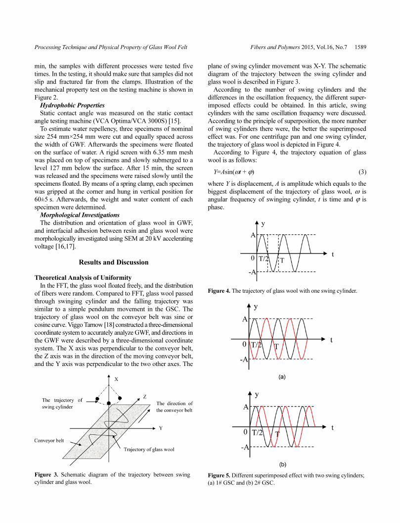
plane of swing cylinder movement was X-Y. The schematic
diagram of the trajectory between the swing cylinder and
glass wool is described in Figure 3.
According to the number of swing cylinders and the
differences in the oscillation frequency, the different super-
imposed effects could be obtained. In this article, swing
cylinders with the same oscillation frequency were discussed.
According to the principle of superposition, the more number
of swing cylinders there were, the better the superimposed
effect was. For one centrifuge pan and one swing cylinder,
the trajectory of glass wool is depicted in Figure 4.
According to Figure 4, the trajectory equation of glass
wool is as follows:
Y=Asin(ωt + ϕ) (3)
where Y is displacement, A is amplitude which equals to the
biggest displacement of the trajectory of glass wool, ω is
angular frequency of swinging cylinder, t is time and ϕ is
phase.
Figure 3. Schematic diagram of the trajectory between swing
cylinder and glass wool.
Figure 4. The trajectory of glass wool with one swing cylinder.
Figure 5. Different superimposed effect with two swing cylinders;
(a) 1# GSC and (b) 2# GSC.

1590 Fibers and Polymers 2015, Vol.16, No.7 Yong Yang et al.
When the number of swing cylinders was more than one,
the trajectory of glass wool could be superimposed. According
to the phase difference and the number of swing cylinders,
different superimposed effects could be obtained. According
to the production of experimental conditions, two swing
cylinders were used to produce GWF in actual production
line. In this case, the most important and best ways of
superimposition are in Figure 5. This process is defined as
1# GSC and 2# GSC in Figure 5(a) and Figure 5(b),
respectively.
Uniform Performance
The GWF were manufactured by FFT and GSC, and the
uniform performance of the GWF from these two methods
were examined and compared. The data of non-uniformity is
described in Figure 6, and the appearance of GWF is shown
in Figure 7. Obviously, there were some blind pores in the
surface of the sample produced by FFT, and the uniformity
of the sample from GSC was superior to FFT. The mean data
of non-uniformity for FFT sample was 10 % and while non-
uniformity of method 1# of GSC was closed to 8 % and for
method 2# of GSC was half of FFT’s. Phase difference of
1# GSC with two swing cylinders was π +2kπ, and the
superimposed section of GWF was mainly limited to the
middle part of conveyor belt, however the glass wool was
relatively small at intervals. Compared to the middle part,
the edging portion of GWF was distributed unevenly in the
production. Phase difference of 2# GSC was π/2+2kπ. The
superimposed section of glass wool almost covered the
whole conveyor belt. The fibers of GWF with smooth
surface were distributed more uniformly. Sirok et al. [19]
and Blagojevic et al. [20] researched the relations between
the parameters of mineral wool production and mineral wool
distribution, and they found the uniform mineral wool
distribution in the primary layer significantly affected the
final product quality. The uniformity affected the physical
and mechanical properties of GWF and hence through GSC,
excellent uniformity with phase difference of π/2 +2kπ
could be obtained.
Tensile Strength
The relationship between tensile strength and breaking
length of GWF is plotted in Figure 8. It was obvious that
tensile strength increased simultaneously with breaking
length. The tensile strength for the GWF with GSC was
much higher than those with FFT. Glass wool passed through
swinging cylinder, and part was guided into a small amount
fiber bundle on the surface of GWF. The bundle fiber played
Figure 6. The data of uniformity of GWF by both FFT and GSC.
Figure 7. GWF with FFT versus GSC’s; (a) FFT, (b) 1#GSC, and (c) 2# GSC.
Figure 8. Tensile strength versus fragment length of GWF.

Processing Technique and Physical Property of Glass Wool Felt Fibers and Polymers 2015, Vol.16, No.7 1591
an important role in this improvement and it was equivalent
to a small amount of strengthened fibers to enhance the
strength of GWF, which allowed the GWF to have high
force transfer length along the fiber bundle. Fridrikh et al.
[21] and Tan et al. [22] stated that the measurements and
subsequent calculations had most often followed methodologies
used to describe the mechanical strength of bulk solids,
which might not be appropriate for fibrous materials because,
unlike bulk solids, the properties of fibrous materials depended
not only on the material of the bulk solid, but also on the
structure of the matrix, e.g. fiber diameter, fiber curvature,
fiber alignment, fiber density. Tensile strength and Young’s
modulus of the material were directly affected by the fiber
length distribution function and fiber orientation. Thomasson et
al. [23] suggested that composites with longer glass fibers
usually had greater stiffness and strength than those with
shorter glass fibers. However, in this paper, the fiber length
distribution function was constant, and the fiber orientation
was changed along with the different processes. The GSC
was observed to have higher arrangement level of fibers as a
result of having two-dimensional distribution, conversely to
the random distribution such as three-dimensional distribution
in FFT. This phenomenon is shown in Figure 9, where that
the fibers with two-dimensional distribution exhibited high
tensile strength, compared to the three-dimensional distribution.
Most fibers with two-dimensional distribution lay in the
same plane, and while the fibers were fused to each other,
the friction between the fibers was not ignored. Therefore,
the fibers that spanned the entire GWF longitudinally could
bear the tensile load.
The tensile force versus elastic deformation of different
samples by FFT and GSC are shown in Figure 10. The results
shown that there were a large difference in appearance of
these curves, the reasons were that fibrous materials existed
non-uniform feature in the process of preparation, and in the
Figure 9. SEM micrographs of GWF; (a) FFT and (b) GSC. Figure 10. The tensile force versus deform length of GWF.
1592 Fibers and Polymers 2015, Vol.16, No.7 Yong Yang et al.
test the samples did not slip and fractured far from the
clamps, however the different distances between breaking
point and clamps led to difference curves. The elastic
deformation reached a maximum value corresponding to the
biggest tensile force. The length of elastic deformation of
FFT and GSC were 3-6 mm and 6-8.7 mm, respectively. The
elastic deformation of GSC was larger than FFT. The elastic
deformation of GWF was dependent on the curvature of the
length of the longest fiber. The fibers in three-dimensional
were curved, and provided very little tensile force. The
uniformity, the fiber bundle and the arrangement level of
fibers led to the GWF with large elastic deformation.
These results were consistent with the uniform values of
the samples and the process of GSC. Usually, GWF with
higher uniformity translated into higher tensile strength,
breaking length and elastic deformation. There was a significant
improvement in physical properties and tensile strength by
addition of swing cylinder.
Hydrophobic Properties
Static Contact Angle
The static contact angle referred to the phenomenon where
water droplets fell onto a level solid surface. Latva-Kokko et
al. [24] stated that the wetting ability was controlled by the
pairwise interfacial energies of the two fluids and the solid,
and it could be characterized by a contact angle. The contact
angle was the angle formed by the intersection of the interfaces
bounding the three phases. The tangent of solid-liquid interface
and gas-liquid interface clamp the liquid phase in the
formation of the angle as shown in Figure 11.
Dimitri et al. [25] stated that the relation between contact
angle and surface tension is as follows:
(4)
where θe is the measured contact angle and γ is the surface
energy of the solid-vapor (SV), solid-liquid (SL) and liquid-
vapor (LV) interface.
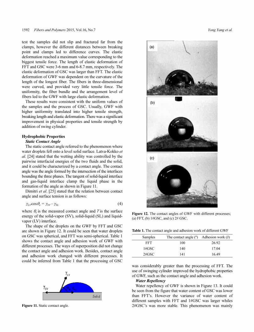
The shape of the droplets on the GWF by FFT and GSC
are shown in Figure 12. It could be seen that water droplets
on GSC was spherical, and FFT was semi-spherical. Table 1
shows the contact angle and adhesion work of GWF with
different processes. The ways of superposition did not change
the contact angle and adhesion work. Besides, contact angle
and adhesion work changed with different processes. It
could be inferred from Table 1 that the processing of GSC
was considerably greater than the processing of FFT. The
use of swinging cylinder improved the hydrophobic properties
of GWF, such as the contact angle and adhesion work.
Water Repellency
Water repellency of GWF is shown in Figure 13. It could
be seen from the figure that water content of GSC was lower
than FFT’s. However the variance of water content of
different samples with FFT and 1#GSC was larger whiles
2#GSC’s was more stable. This phenomenon was mainly
γLVcosθe γSV γSL–=
Figure 11. Static contact angle.
Figure 12. The contact angles of GWF with different processes;
(a) FFT, (b) 1#GSC, and (c) 2# GSC.
Table 1. The contact angle and adhesion work of different GWF
Samples The contact angle (º) Adhesion work (J)
FFT 100 26.92
1#GSC 140 17.04
2#GSC 141 16.49

Processing Technique and Physical Property of Glass Wool Felt Fibers and Polymers 2015, Vol.16, No.7 1593
due to the uniformity of GWF. During the test procedure,
water was mainly absorbed into the interior of GWF leading
to high water content. In the FFT, there were some blind
pores in the surface. The profile of blind pores increased the
area of suction and had certain function for storing water.
Water content of 1#GSC and 2#GSC were close to each
other though 2#GSC was slightly better than 1#GSC. Firstly,
fiber bundle and two-dimensional distribution made GWF
with smooth surface, whereas high uniformity led a small
amount closed pores. Secondly, large contact angle and small
adhesion work made GWF with strong water repellency. This
was why the water repellency of 2#GSC was superior to that
of 1#GSC and FFT. In other words, water content decreased
with addition of uniform GWF.
Conclusion
In this paper, GWF was fabricated by means of centrifugal
process, and there were two different methods to guide the
glass wool, which were free float type (FFT) and guided
swing cylinder (GSC). The uniformity affected tensile
strength and hydrophobicity properties of GWF, and the best
uniform process was the swing cylinders with phase difference
of π/2+2kπ. The tensile strength for the GWF with GSC was
much higher than those with FFT. Glass wool passed
through swinging cylinder, and part was guided into a small
amount fiber bundle on the surface of GWF leading to
enhance the strength of GWF. In these processes, the GSC
had higher arrangement level of fibers as a result of having
two-dimensional distribution, conversely to the random
distribution such as three-dimensional distribution in FFT.
Fibers with two-dimensional distribution lay in the same
plane and fused to each other, the friction between the fibers
improved the tensile strength of samples.
The maximum static contact angle and minimum water
repellency of GWF by GSC were 141 o and 15 g, in contrast
to FFT which were 100 o and 26.92 g, respectively. The
results showed that water droplets on GSC was spherical,
FFT was semi-spherical, and water content of GSC was
lower than FFT’s. In the FFT, there were some blind pores in
the surface, and the profile of blind pores increased the area
of suction and had certain function for storing water. Fiber
bundle and two-dimensional distribution made GWF with
smooth surface, whereas high uniformity led a small amount
closed pores, and large contact angle and small adhesion
work made GWF with strong water repellency. A better
uniformity improved tensile strength and hydrophobicity,
and it was demonstrated that optimizing the processes
improved uniformity greatly, obtaining GWF with stable
physical and mechanical properties.
Acknowledgements
Thanks the finial support of Jiangsu Collaborative Innovation
Center for Advanced Inorganic Function Composites. This
work was also supported by Major Achievements of Jiangsu
Province (BA20130987) and Development of Vacuum
Insulation Panel of China Building Cooperative Research
(2015DFI53000), respectively.
References
1. K. É. Goryainov, R. M. Serafimova, and V. I. Pestsov,Glass Ceram., 34, 294 (1977).
2. H. Ku, H. Wang, N. Pattarachaiyakoop, and M. Trada,Compos. Pt. B-Eng., 42, 856 (2011).
3. B. Champagne and R. Angers, Int. J. Powder Metall.
Powder Technol., 16, 359 (1980).4. Y. Z. Liu, K. Minagawa, H. Kakisawa, and K. Halada, Int.
J. Powder Metall., 39, 29 (2003).5. H. L. Cox, Br. J. Appl. Phys., 3, 72 (1952).6. C. F. Yang, Ph.D. Thesis, University of Washington, 1975.7. M. Rigdahl, B. Westerlind, and H. Hollmark, J. Mater. Sci.,
19, 3945 (1984).8. S. Heyden, Ph.D. Thesis, Lund University, 2000.9. N. Venkateshwaran, A. Elayaperumal, and G. K. Sathiya,
Compos. Pt. B-Eng., 43, 793 (2012).10. A. Ridruejo, C. González, and J. Lorca, J. Mech. Phys.
Solids, 58, 1628 (2010).11. M. S. Rizvi, P. Kumar, D. S. Katti, and A. Pal, Acta
Biomater., 8, 4111 (2012). 12. A. Kulachenko, T. Denoyelle, S. Galland, and S. B. Lindström,
Cellulose, 19, 793 (2012).13. S. Borodulina, A. Kulachenko, S. Galland, and M. Nygårds,
J. Pulp. Pap. Sci., 27, 318 (2012).14. Y. Z. Liu, Mater. Sci. Technol., 18, 929 (2002).15. B.-Y. Chen, Y.-S. Wang, H. Y. Mi, P. Yu, T. R. Kuang, X. F.
Peng, and J. S. Wen, J. Appl. Polym. Sci., 131, 41181 (2014).16. Y. Zhaogang, G. Awuti, C. Yi, Z. Jing, W. Boshen, W.
Jianchen, L. Wanliang, Z. Xuan, and Z. Qiang, J. Chinese
Pharm. Sci., 15, 69 (2006).
Figure 13. Water repellency of different samples by FFT and
GSC.

1594 Fibers and Polymers 2015, Vol.16, No.7 Yong Yang et al.
17. L. Chang, M. Howdyshell, W. C Liao, C. L. Chiang, D.GallegoPerez, Z. Yang, W. Lu, J. C. Byrd, N. Muthusamy,L. J. Lee, and R. Sooryakumar, Small, 11, 1818 (2015).
18. V. Tarnow, J. Acoust. Soc. Am., 111, 2735 (2002).19. B. Sirok, B. Blagojevic, and M. Novak, Glass Technol., 43,
188 (2002).20. B. Blagojevic and B. Sirok, Glass Technol., 43, 120
(2002).21. S. V. Fridrikh, J. H. Yu, M. P. Brenner, and G. C. Rutledge,
Phys. Rev. Lett., 90, 1 (2003).22. E. P. S. Tan and C. T. Lim, Compos. Sci. Technol., 66, 1102
(2006). 23. J. L. Thomasson and M. A. Vlug, Compos. Pt. A-Appl. Sci.
Manuf., 127, 477 (1996). 24. M. Latva-Kokko and H. Rothman, Phys. Rev. E, 72, 046701
(2005). 25. D. Janssen, R. D. Palma, S. Verlaak, P. Heremans, and W.
Dehaen, Thin Solid Films, 515, 1433 (2006).


![조선F 15년 1월2주 0117-최종(한유건)18173632]conjapan.pdf · HI조선/해양Flash -15년01월2주 2015. 01. 18 [281호] 최광식(02-2122-9197) gs.choie@hi-ib.com 신조선가](https://img.dokumen.tips/doc/110x75/6028e29714acf362dc2b3f2a/f-15e-12-0117-oeoeoee-18173632-hiflash.jpg)


