Embed Size (px)
Citation preview

Multidisciplinary Senior Design ConferenceKate Gleason College of Engineering
Rochester Institute of TechnologyRochester, New York 14623
Project Number: P13457
DRESSER-RAND ROTOR CELL PRODUCTIVITYAllison Doster Industrial & Systems EngineeringKatherine Poehlman Industrial & Systems EngineeringWilliam Slaughter Mechanical EngineeringWilliam Swift Industrial & Systems EngineeringMichael Then Industrial & Systems Engineering
ABSTRACT
The goal of Rotor Cell Productivity project is to increase the production capacity of the Dresser-Rand Olean, New York plant as it experiences considerable growth and has become starved for space. The floor space and utilities within several areas of the plant will be redesigned to accommodate a more effective flow of parts. The project was split up in order to achieve improvements in the different processing areas based on Dresser-Rand’s needs. The team worked closely with the people at Dresser-Rand to develop needs, collect data, and initiate various improvement projects at their facility, which will be outlined in the publications. The mentor for this team was John Kaemmerlen of the Industrial and Systems Engineering department.
NOMENCLATURE
B&OS: Balance and Over Speed MSD: Multidisciplinary Senior DesignDR: Abbreviation for Dresser-Rand CNC: Computer Numerical ControlWIP: Work in Process
INTRODUCTION
The Dresser-Rand plant in Olean, NY has seen significant growth to its business in recent times. In order to accommodate the growth successfully, the company needs to improve upon their current facility’s space since an expansion is not an option at this time. Understanding the current throughput of the plant and different options to increase this throughput is the most valuable step. Not only does it reveal a variety of wastes in current processes that could be changed in the scope of this project, but it also revealed areas for future changes for DR to take on in their own time. The overall goal of increasing productivity in the Rotor Cell through facility improvements benefits DR employees of all levels. It helps the job of the operators who interact with the systems daily, the supervisors who need to decide on production, and displays to upper management the potential of the facility. There are several locations within the plant that revealed themselves as areas that could use substantial improvements. The Balance and Over Speed process, Heat Treat process and the Milling process are all critical processes for all types of impellers. In order to accomplish valuable changes for DR, the RIT team chose to focus on these three critical areas in order to make the most substantial impact.
Copyright © 2013 Rochester Institute of Technology
Proceedings of the Multidisciplinary Senior Design Conference Page 2
DESIGN PROCESS
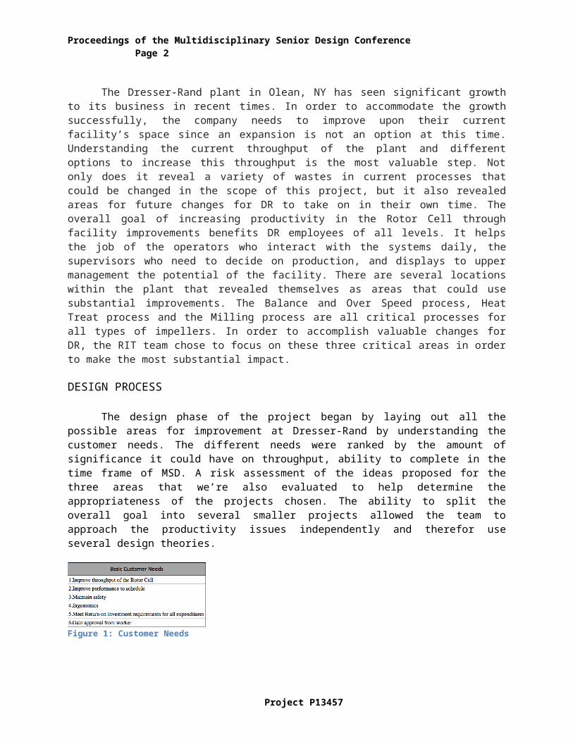
The design phase of the project began by laying out all the possible areas for improvement at Dresser-Rand by understanding the customer needs. The different needs were ranked by the amount of significance it could have on throughput, ability to complete in the time frame of MSD. A risk assessment of the ideas proposed for the three areas that we’re also evaluated to help determine the appropriateness of the projects chosen. The ability to split the overall goal into several smaller projects allowed the team to approach the productivity issues independently and therefor use several design theories.
Figure 1: Customer Needs
Figure 2: Heat Treat Risk Assessment
Figure 3: B & OS Risk Assessment
CURRENT STATE
The Olean, NY plant us currently facing poor space utilization and floor planning, which puts a huge constraint on the plants ability to manufacture on time. The plant produces customized rotor for turbines, which is build of a set of rotating impellars. The impellars are the main product being milled and processed throughout the plant, where they come together at the end for a final order assembly.
The milling time for any given impeller, depending on complexity, can range from 10hours of machine time. An operator has to be present at the CNC for the machine to be running, so this time can be thought of in man-hours. Most impellars are shipped to outside vendors who help complete the milling work because the plant is past capacity. Not only should these occurrences be minimized because of cost and time involved, it also interferes with ability to track parts.
The new layout for the Balance and Over Speed area will fit into its current floor space of 12’x 21’ but be improved for picking times through layout changes and allow for a minimum of 10% growth through a change in rack design. The current space is extremely underutilized because of the rack design, and they also they make it difficult for the operator to find the parts that need to be processed. It also has no organization by prioritization, which could also significantly decrease picking time.
The Heat Treat oven process, in which all impellers receive as the last step before assembly, is lacking proper storage and organization for the impellars, and therefor increasing the time it takes for its
Project P13457

Proceedings of the Multi-Disciplinary Senior Design Conference Page 3
operators to process the parts through the oven. This 10’x17’ area also lacks part organization by prioritization or any process standardization.
DESIGN PROPOSALS
Heat TreatRacking System
The size of the impellars range from a 6” to 48” diameter, however 80% of the impellars processed are in the diameter range of less than 24”. They must be moved using an overhead crane for ergonomic and safety purposes, which is the main constraint for future state rack design. The team evaluated four potential types of shelving systems, roll out racks, pull out bleacher style, fixed steps, and the basic flow-through pallet racks. As displayed in Figure 4 below, the four systems were ranked based on the Heat Treat criteria. Ability for the overhead crane to access the impellars was the preliminary reasoning for the designs being compared. From there the designs were evaluated by reduction in footprint, the overall goal in the Heat Treat area, and other important factors to be considered.
Figure 4: Racking System Weighted Options
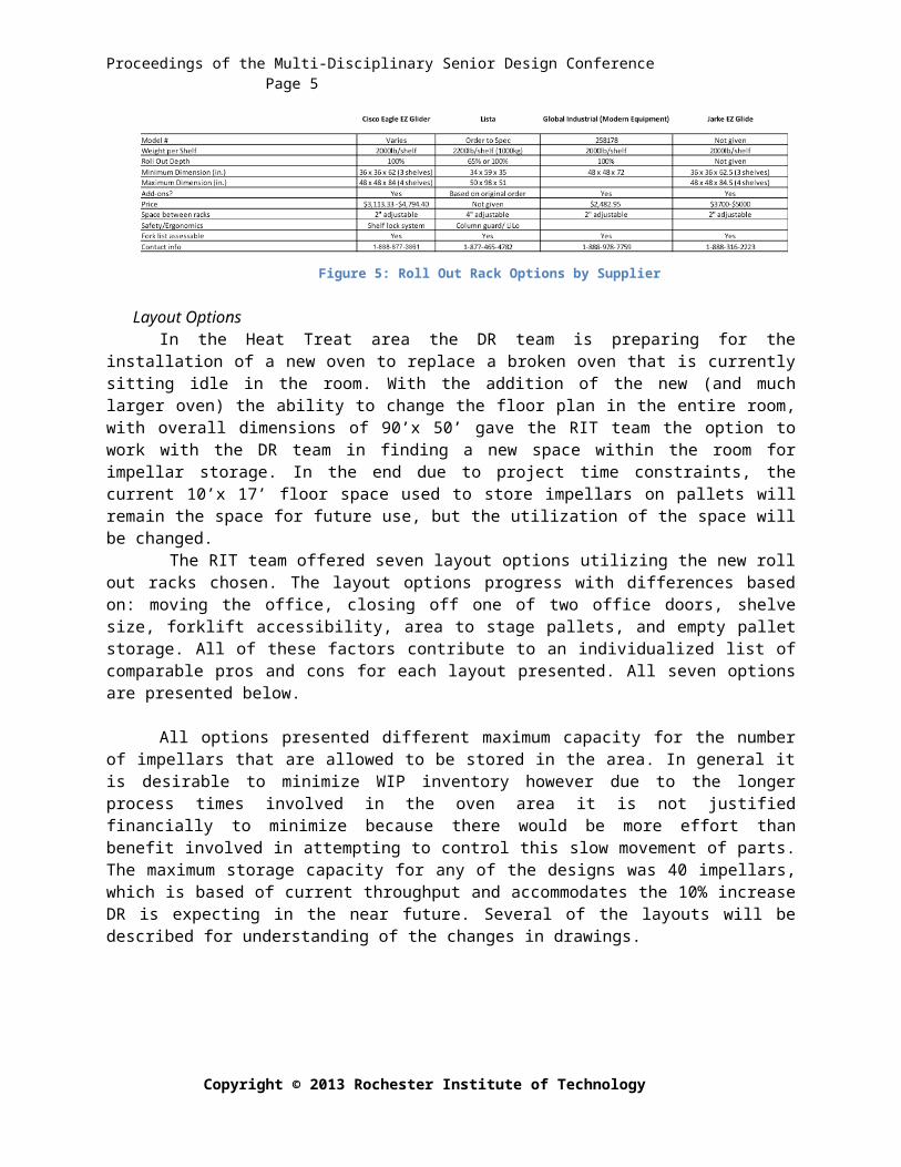
The best rack design option based of this analysis was a roll out rack system. This system is offered as a manufactured product from several companies, which also makes it a more economical choice over the pull out bleacher style or fixed step racking system, which would have had to been custom built. There were several suppliers offering this system, so specifications on size, load rating, and ergonomics were obtained from the suppliers to decide on the best option for the DR facility.
Figure 5: Roll Out Rack Options by Supplier
Layout OptionsIn the Heat Treat area the DR team is preparing for the installation of a new oven to replace a
broken oven that is currently sitting idle in the room. With the addition of the new (and much larger oven) the ability to change the floor plan in the entire room, with overall dimensions of 90’x 50’ gave the RIT team the option to work with the DR team in finding a new space within the room for impellar storage. In the end due to project time constraints, the current 10’x 17’ floor space used to store impellars on pallets will remain the space for future use, but the utilization of the space will be changed.
The RIT team offered seven layout options utilizing the new roll out racks chosen. The layout options progress with differences based on: moving the office, closing off one of two office doors, shelve size, forklift accessibility, area to stage pallets, and empty pallet storage. All of these factors contribute to an individualized list of comparable pros and cons for each layout presented. All seven options are presented below.
Copyright © 2013 Rochester Institute of Technology

Figure 7: Layout 1 Figure 6: Layout 2 Figure 8: Layout 3
Proceedings of the Multidisciplinary Senior Design Conference Page 4
All options presented different maximum capacity for the number of impellars that are allowed to be stored in the area. In general it is desirable to minimize WIP inventory however due to the longer process times involved in the oven area it is not justified financially to minimize because there would be more effort than benefit involved in attempting to control this slow movement of parts. The maximum storage capacity for any of the designs was 40 impellars, which is based of current throughput and accommodates the 10% increase DR is expecting in the near future. Several of the layouts will be described for understanding of the changes in drawings.
Layout one accomplishes a reduction of 30 square feet by shifting the office to as far right as possible by 4’-7”while still allowing employees to utilize both exits. Two of the larger pallet racks were chosen for designated impellar storage, while a large portion of the area was left open for floor storage of moving pallets and empty pallet storage.
Layout two reduces the areas footprint the greatest by reallocating approximately 60 square feet to other operations by rotating the office 90° and closing off one of the exits. Although the design fulfills the customer’s needs while minimizing footprint, it does not leave them with any room for empty pallet storage, which may be desirable for day-to-day operations.
Similar to layout one, layout three option also sees a footprint reduction of 30 square feet. It does not however shift the
office, but accommodates 3 large roll out racks for maximum impellar size variability and storage. The placement of all three racks against the back also allows for pallet staging to occur in front of the storage location, however because of the staging area placement it creates a longer route for forklift drivers.
Balance & Over-SpeedRacking System
The Balance & Over Speed area is a system of shelving that the operators use to store and access parts that are queued to be processed. The current shelving not only has very poor space utilization but it lacks visibility of parts for the operator for quick pick operations. The pick operation also needs to include overhead crane access for the larger impellars that are unsafe for operators to handle. Due to the range in possible sizes of the impellars being stored on these shelves, from 6” and up, a variety of options for future design revealed themselves for consideration. Six shelving designs were proposed, all unique at appealing to different customer needs. Accessibility and visibility of parts, part density, footprint, aisle width and cost remained as the main factors influencing the shelving design and decision making process. Evaluation for load ratings and safety issues were also considered with each system.
Designing a modular shelving unit that would allow for operator access at 360° was the basis for the shelving tree design in concept 1. Smaller, more lightweight impellars would be stored on the parallel shelves to the ground, while the larger impellars would
Project P13457
Figure 9: B&OS Concepts
Proceedings of the Multi-Disciplinary Senior Design Conference Page 5
be stored in vertical slots to greatly minimize the layouts footprint, while maintaining crane access. The shelving may also be stored in tighter, less traditional spaces. There is a risk of stability depending on the loads that may be present at varying times.
Considering the potential stability risk in concept 1, concept 2 was developed as a more robust option. The designed maintained the model of vertical storage for large impellars, but also did so for smaller sized impellars in a “vegetable rack” concept. This vertical racking system allows for the highest part density of all the options evaluated at approximately 108 impellars per shelve. It also allows for 5S to be used because any missing parts could easily be identified as easily as noticing an empty slot. The heftiness of this shelving system however could potentially cost a considerable more to manufacture than other designs.
A third and the most simple of design concepts is a pre-manufactured steel rack that would store the impellars horizontally. These shelves would allow for open accessibility for picking from all sides of the unit and high part density. Concept 3 could also be laid out back-to-back to maximize aisle space or in singular units. This allows for highly effective layout potential.
Layout OptionsWhen the final shelving design had been chosen, the RIT team then worked on layout options for
the DR team to consider. The layout will remain within the current 12’ x 21’ floor space, however because of the change in shelving options, it gave the team several options for placement and orientation of the new shelving. The redesign also considers the operators use of pushcarts to access parts when picking, and the ability to access the overhead crane when picking the larger impellars.
The new shelves in the Balance and Over Speed area dimensioned at 60” tall, 24” deep and 72” wide for the re-layout. The Dresser-Rand team also requested the use of one of the same pull out style racks that was chosen for the Heat Treat area to also be purchased for B&OS to store larger impellars. The analysis for the racks chosen for the B&OS area is discussed below in the Future State section. Two effective layout models were exhibited to the DR team to choose based on preference. Both models allow for frontal and end access to all of the steel racks and contribute to a single direction picking flow.
Visual SchedulingManagement at Dresser-Rand is currently experiencing redundant work with their scheduling
system. The current practice is to have a morning meeting to decide the schedule of work for the next 24 hours. Once the schedule has been decided it is manually written on white boards around the workstations. If there is an engineering change order than all the white boards have to be manually changed, which can take several hours.
Copyright © 2013 Rochester Institute of Technology
Figure 9: B&OS Concepts
Figure 10: B&OS Shelving
Figure 11: B&OS Layout Alternatives

Proceedings of the Multidisciplinary Senior Design Conference Page 6
To remedy the situation, DR wants a system in place so that the “hot list” for the day can be created on excel and inputted into a system so that it can be displayed on monitors on the floor. This will allow the same schedule to be managed remotely and be shown in the cells in real time. All displays will be managed from the same source, but different schedules will appear on each monitor. Dresser-Rand will start with two monitors and will later expand to eleven locations, with seven having high volume.
The RIT senior design team contacted a local IT consulting company called DataBranch to discuss feasible solutions with the given requirements.
The solution that all parties agreed would be the best fit is centered on a software called Hiperwall, which will run on a separate connection from DR’s main network. The displays will consist of 46’’ LCD monitors which will be mounted to the wall using a tilt wall mount. DataBranch has provided the opportunity for instillation, but DR can also chose to have their own IT department take care of the implementation.
Vectra TableConcept Development
This project was issued early in the second quarter at our request for more potential improvement projects. The shop manager realized that the there was potential for process improvement if tooling modifications could be made to the Vectra assembly table. We traveled to the site to see the table and start gathering information about the process and the issues he wanted to improve.
The current process required that the Vectra assemblies be relocated from the vertical position on the table where blades were installed to a horizontal position for rotational balancing and inspection. This was necessary to perform run-out measurements on the newly installed blades. Vectra assemblies weigh upwards of 2,000 lb., so making this move took valuable time. In order to reduce this time, Dresser-Rand sought to modify the Vectra table so the run-out inspection could be done from the vertical position. The system we proposed needed to allow the 2,000 lb. assembly to rotate completely vertically within a .0001in tolerance. Dresser-Rand (DR) wanted the proposed design to make use of the current table, while allowing the rotor to be rotated smoothly by hand. The current process made use of a mounting collar that held the rotor within a 15 inch diameter hole in the center of the table. The fan blades then sit above the table and the shaft of the rotor extends below the table to the floor.
To fully examine all the concept possibilities, it would have been preferable to have been given this project during the first quarter of Senior Design. Given this limited time, it was necessary to accelerate the design process and develop the concept as quickly as possible. Our first concept made use of the collar by installing a rotary bearing around the hole in the table. The collar could then rest on the rotary bearing, allowing the assembly to rotate. However, when we discussed this concept with DR, they expressed their desire to eliminate the use of the collar altogether. Because of the high tolerance of the measurements, mounting the collar would add too much variability to the measurements of the run-out, so we had to redesign.
Without the collar, we needed a way to support the assembly from the bottom that allowed rotation. We would also need to have a means of supporting the shaft of the Vectra rotor so it would stand perfectly vertical. At DR, they currently make use of v-blocks to rotate shaft on a horizontal axis. The components consist of two precision ground wheels that can be set against the shaft for support. Their high tolerance made them ideal for supporting the Vectra shafts from the sides. We made use of the v-blocks by mounting two of them below the table on either side of the hole. One of the v-blocks would be fixed in place and the other would ride on a rail and would be driven into place by a screw drive
Project P13457
Figure 12: Vectra Table Concept

Figure 15: Chosen Proposal
Proceedings of the Multi-Disciplinary Senior Design Conference Page 7
assembly. When the Vectra rotor is placed on the base, the v-block would merge toward the center, and both v-blocks would press against the shaft of the rotor.
It is imperative the center of rotation of the shaft be concentric with the axis of rotation of the base and the center of the v-block. The base of our system is comprised of a rotary bearing and a base plate. The base plate would be a turned steel plate with a nose cone in the center. This plate would then be mounted on a rotary bearing that could support the 2000lbs load. At the center of the rotor is a machined hole that is the center of rotation from when the shaft was lathed. This nose is in place to ensure that the base is always centered and to avoid the “walking effect”. If the base was flat, and the rotors were not aligned to the center of rotation for the base rotary bearing, the rotor would have a tendency to walk across the surface. Raising the rotor off the bottom gives the rotor the ability to pivot and center itself in the v-blocks. It also gives the operator a visual confirmation that the rotor is centered. Ideally, the
system would only need to be aligned once, but the procedure for how this could be done has not yet been worked out.
FUTURE STATE
Heat Treat
The detailed design review allowed the team to present the final layout and racking designs to the Dresser Rand team in a discussion based setting. As mentioned earlier, the decision was made that the roll out racks would perform the best for the intended part storage and fulfill the primary goal of footprint reduction. The racks chosen are dimensioned 48”x 48” and have a 2000 lb. load maximum per shelf. Each shelf can be height adjusted to accommodate the user and varying part size. Each shelf take a 15 lb. pull force from the user to access a full loaded shelve. The unit will be bolted to the floor to eliminate the safety
risk of tipping while the shelving also has a standard lock mechanism built in to keep the user from having more than one shelf open at a
time. From there, DR evaluated their floor plan options and decided on Option 3. Option 3 makes use of three large racks for accommodating the greatest part size variability and still allows for easy manual, forklift and overhead crane access. The new layout storage holds a maximum of 24-40 impellars depending on size, which allows for the 10% growth defined in the customers future needs. The choice accomplishes the projects goal and also comes at a minimal cost to the company by not having to pay for the office to be moved.
Capacity Determination
Copyright © 2013 Rochester Institute of Technology
Figure 13: V-Block Concept
Figure 14: Base Plate Concept

Proceedings of the Multidisciplinary Senior Design Conference Page 8
Arena based Capacity ModelThe effort with the arena model hit significant snags over the course of the project. The intention
for this model was to provide valid assessments for future capital improvement projects and determine the overall internal capacity. Our team worked with an engineer at DR who was constructing the arena model. Our role was to perform the data analysis portion of the effort.
Data was pulled from the production archive of process times for various part types. With this information, we hoped be able to ascertain valuable statistics about the production volumes and processing rates for parts. These statistics would become the basis for the model. The issue we came across what that the data in their system was not complete enough to make any valuable conclusions during our time on the project. It was also difficult to troubleshoot discrepancies in the data when wnot working on site.
The effort is continuing at DR without our input, however, we were able to help the engineer formulate his model logic and a survey was put together in order to capture the critical statistics through general consensus. As was stated before, this project is ongoing so the outcome is uncertain. If they are able to make this model work, it should teach them a lot about their process and how to manage parts flow efficiently.
CONCLUSIONS AND RECOMMENDATIONS
This project has just scratched the surface of the potential improvement opportunities at Dresser- Rand. While we were not able to implement our concepts, we have initiated the improvement effort by providing insight into different ways to improve a process and areas where we’ve identified significant waste. The struggle that Dresser-Rand will have moving forward is eliminating their reactive work schedule due to a variable work load. Our efforts have also uncovered significant holes in production information that have the potential to make vast improvements capacity by managing their work balance effectively between in-house and outsourced work. It is out recommendation that a future senior design team pick up with the Vectra table concept if it is still Dresser-Rand’s wish to pursue this opportunity in the future.
ACKNOWLEDGEMENTS
The RIT team would like to thank those who have supported the Rotor Cell Productivity project at all phases of development. We would like to especially thank Professor John Kaemmerlen for his friendly guidance and professional knowledge in allowing us to achieve the goals we had set. Also, the following Dresser-Rand employees deserve a sincere thank you for their support and valuable input to the team from start to finish: DJ Dick, Sean Frier, Joseph Hannold, Andy Morino and Andrew Morrell.
Project P13457