Embed Size (px)
DESCRIPTION
Procedure Design Considerations. BEIJING, CHINA; 30 JUN-11 JUL 2014. Learning Objectives. By the end of this presentation you should understand: Procedure design considerations including : Path Terminators Waypoint Types Factors affecting turn radius. Conceptual Design: What Next?. - PowerPoint PPT Presentation
Citation preview
Procedure Design Procedure Design ConsiderationsConsiderations
Procedure Design Procedure Design ConsiderationsConsiderations
BEIJING, CHINA; 30 JUN-11 JUL 2014
Learning ObjectivesLearning ObjectivesLearning ObjectivesLearning Objectives
✈ By the end of this presentation you should understand:By the end of this presentation you should understand:
✈Procedure design considerations including:Procedure design considerations including:✈Path TerminatorsPath Terminators
✈Waypoint TypesWaypoint Types
✈Factors affecting turn radiusFactors affecting turn radius
22
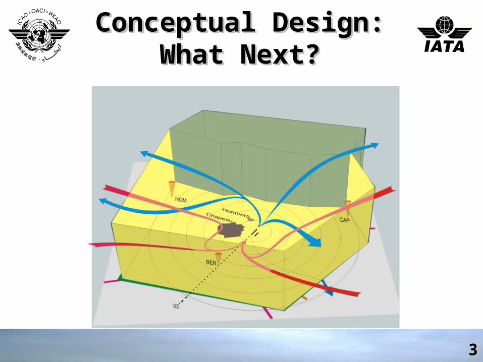
Conceptual Design: What Conceptual Design: What Next?Next?
Conceptual Design: What Conceptual Design: What Next?Next?
33
Procedure Design Procedure Design ConsiderationsConsiderations
RNAV Path TypesRNAV Path Types
Procedure Design Procedure Design ConsiderationsConsiderations
RNAV Path TypesRNAV Path Types
44
5
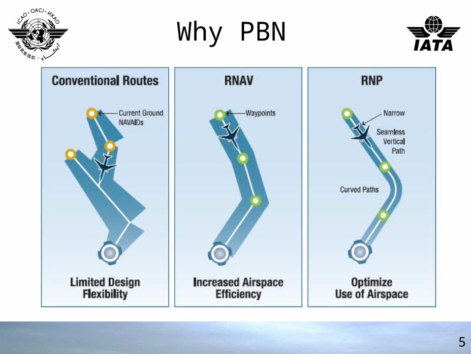
Why PBN
Slide 6
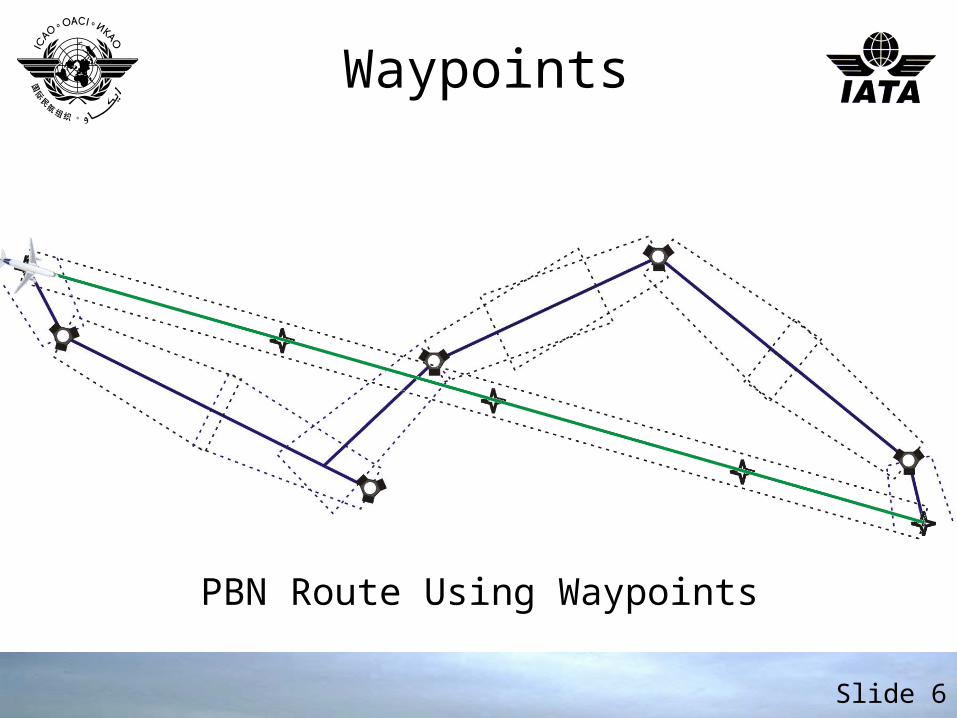
PBN Route Using Waypoints
Waypoints
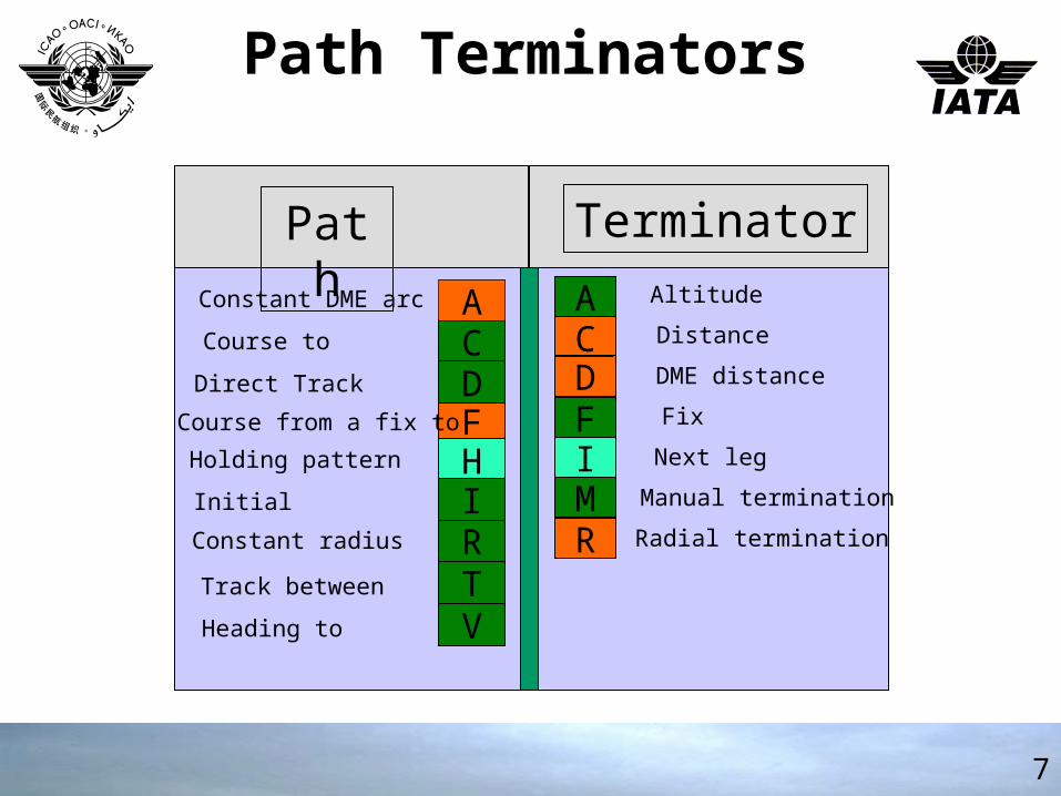
Path TerminatorsPath Terminators
7
TerminatorPath
CA
DFI
MR
Altitude
Distance
DME distance
Next leg
Manual termination
Radial termination
FixF
Constant DME arc
Course to
Direct Track
Course from a fix to
Holding pattern
Initial
Constant radius
Track between
Heading to
CD
H
R
A
I
VT
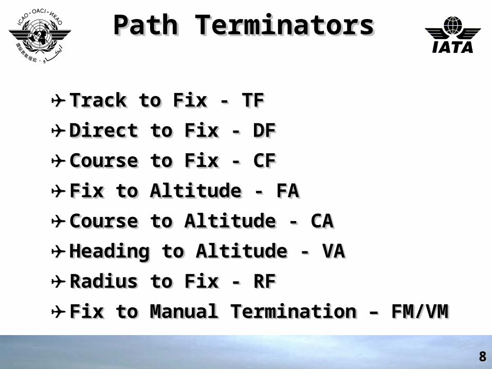
Path TerminatorsPath TerminatorsPath TerminatorsPath Terminators
✈ Track to Fix - TFTrack to Fix - TF
✈ Direct to Fix - DFDirect to Fix - DF
✈ Course to Fix - CFCourse to Fix - CF
✈ Fix to Altitude - FAFix to Altitude - FA
✈ Course to Altitude - CACourse to Altitude - CA
✈ Heading to Altitude - VAHeading to Altitude - VA
✈ Radius to Fix - RFRadius to Fix - RF
✈ Fix to Manual Termination – FM/VMFix to Manual Termination – FM/VM
88
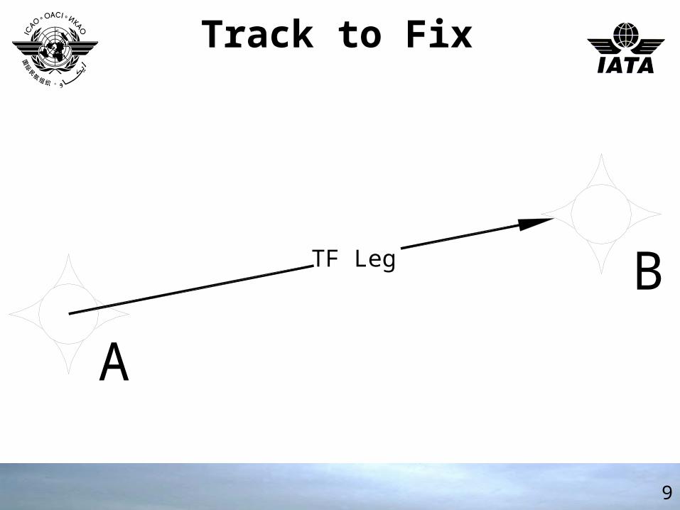
Track to FixTrack to Fix
9
TF Leg
A
B
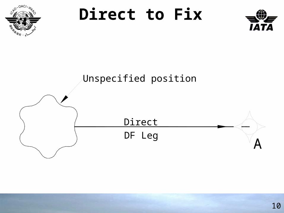
Direct to FixDirect to Fix
10
DirectDF Leg
Unspecified position
A
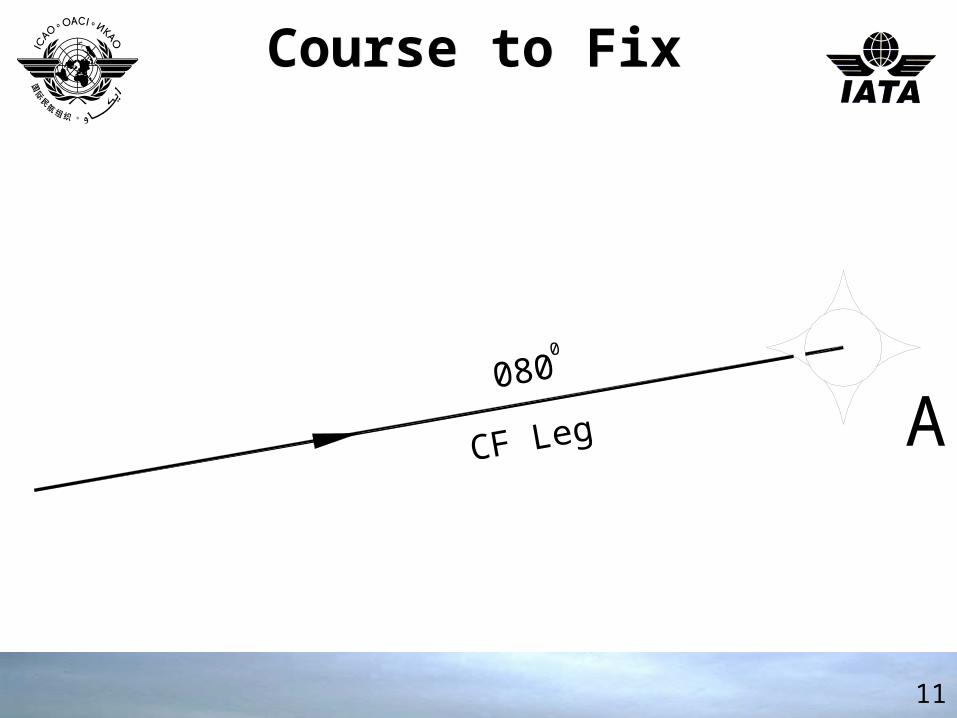
Course to FixCourse to Fix
11
CF Leg
080
A0
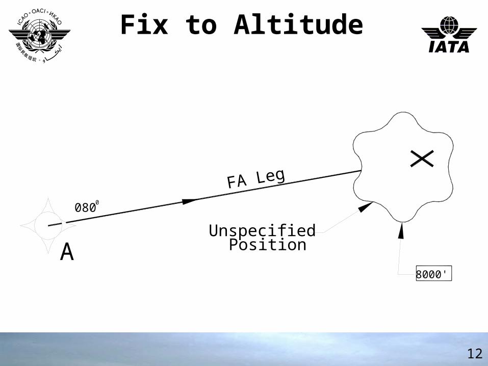
Fix to AltitudeFix to Altitude
12
AUnspecified
Position
8000'
FA Leg
0800
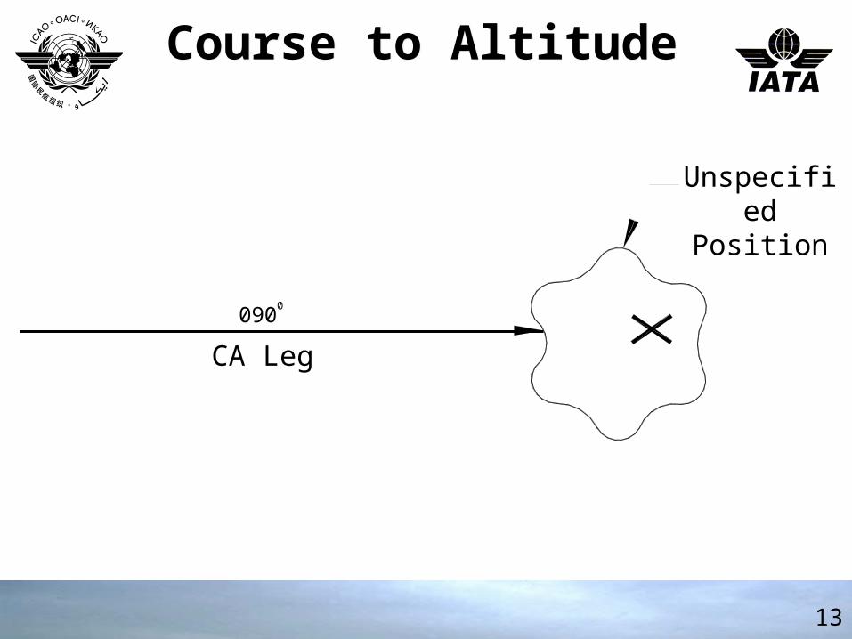
Course to AltitudeCourse to Altitude
13
Unspecified Position
CA Leg
0900
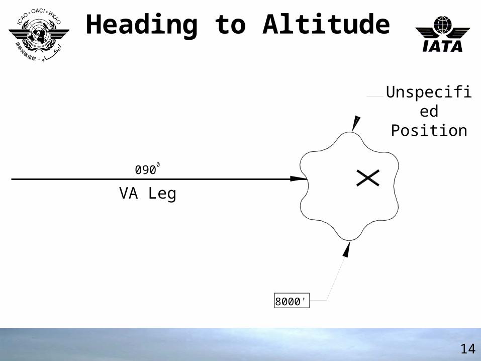
Unspecified Position
VA Leg
0900
8000'
Heading to AltitudeHeading to Altitude
14
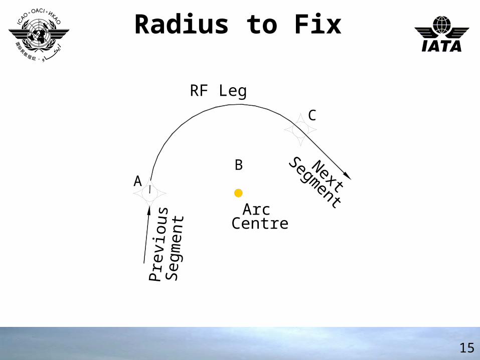
Radius to FixRadius to Fix
15
Pre
viou
sS
egm
ent Arc
Centre
NextSegm
entA
C
B
RF Leg
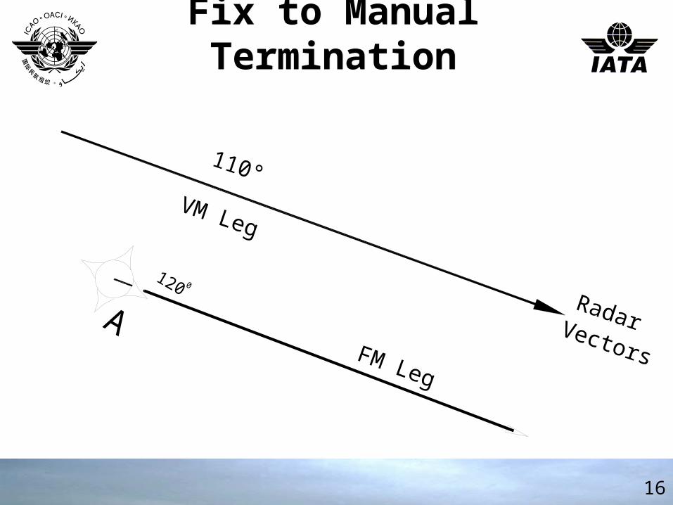
Fix to Manual TerminationFix to Manual Termination
16
110°
VM Leg
RadarVectors
AFM Leg
120 0
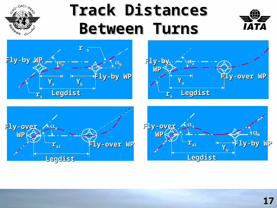
Track Distances Between Track Distances Between TurnsTurns
Track Distances Between Track Distances Between TurnsTurns
1717
YYaa YYbb
aa bb
LegdistLegdist
Fly-by WPFly-by WP
Fly-by WPFly-by WP
rraa
r r bb
YYaa
aa
LegdistLegdist
Fly-byFly-byWPWP
Fly-over WPFly-over WP
rraa
aa
LegdistLegdist
Fly-overFly-overWPWP
rra1a1 YYbb
bb
Fly-by WPFly-by WP
aa
LegdistLegdist
Fly-overFly-overWPWP
Fly-over WPFly-over WPrra1a1
18
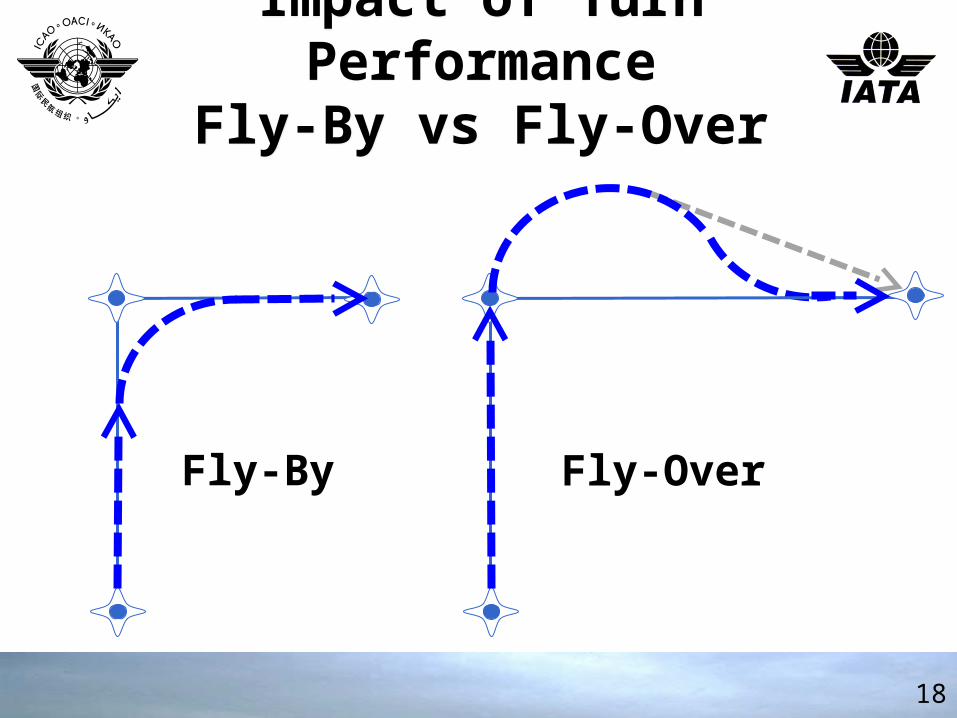
Impact of Turn PerformanceFly-By vs Fly-Over
Impact of Turn PerformanceFly-By vs Fly-Over
Fly-By Fly-Over
Q2*t95-(43r/2)
19
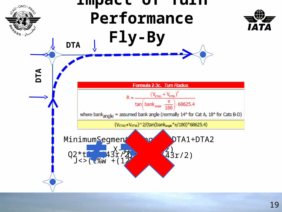
Impact of Turn PerformanceFly-By
Impact of Turn PerformanceFly-By
DTAD
TA
MinimumSegment Length= DTA1+DTA2X-y2/(-9/43z)
Q2*t95-(43r/2)J<>(t%w +(12#d-p4))
20
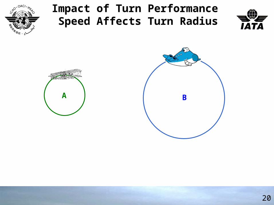
Impact of Turn Performance Speed Affects Turn Radius
Impact of Turn Performance Speed Affects Turn Radius
A B
21
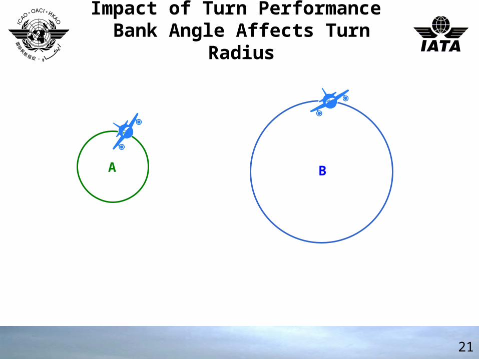
Impact of Turn Performance Bank Angle Affects Turn Radius
Impact of Turn Performance Bank Angle Affects Turn Radius
A B
22
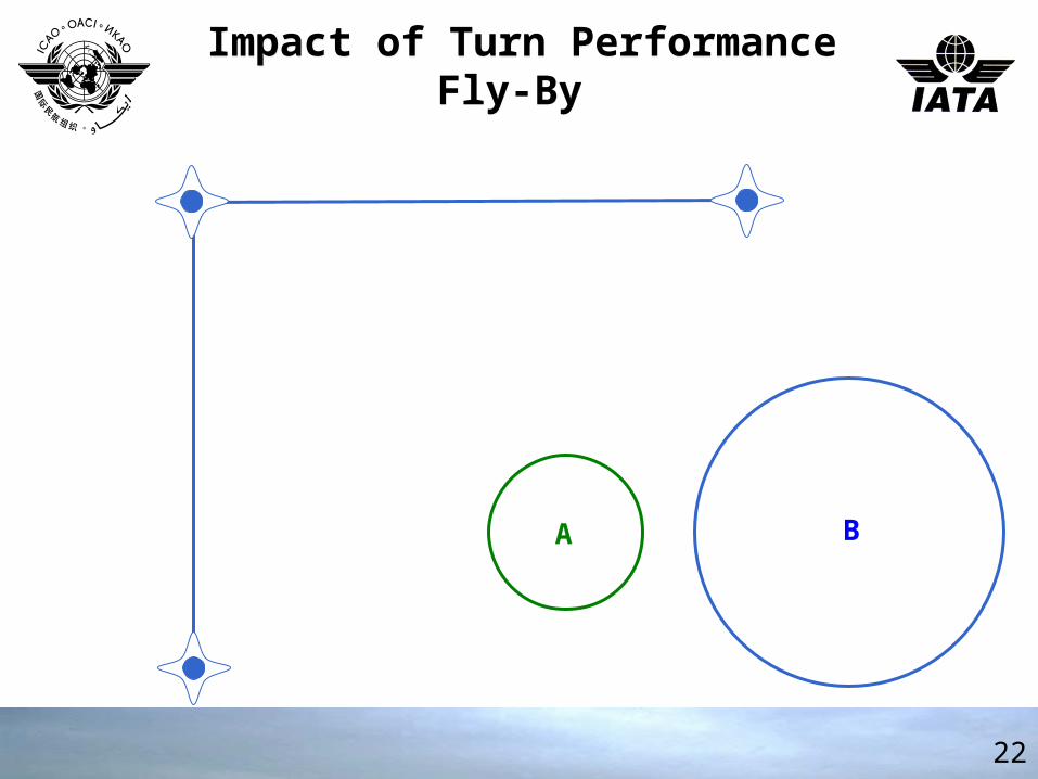
Impact of Turn PerformanceFly-By
Impact of Turn PerformanceFly-By
BA
23
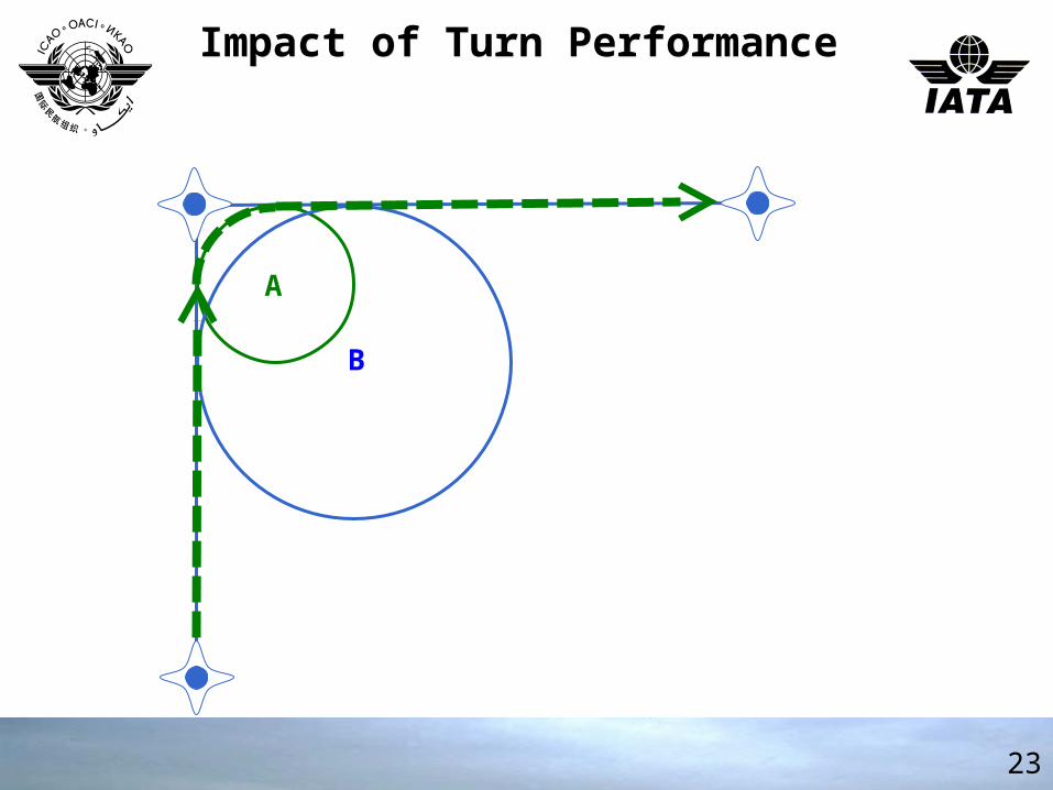
Impact of Turn Performance Impact of Turn Performance
A
B
24
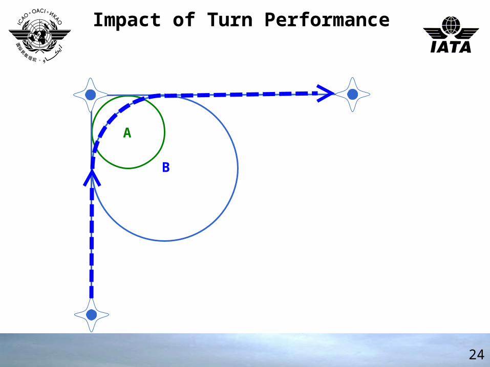
Impact of Turn Performance Impact of Turn Performance
A
B
25
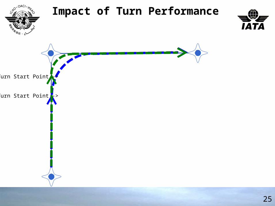
Impact of Turn Performance Impact of Turn Performance
Turn Start Point ->
Turn Start Point ->
26
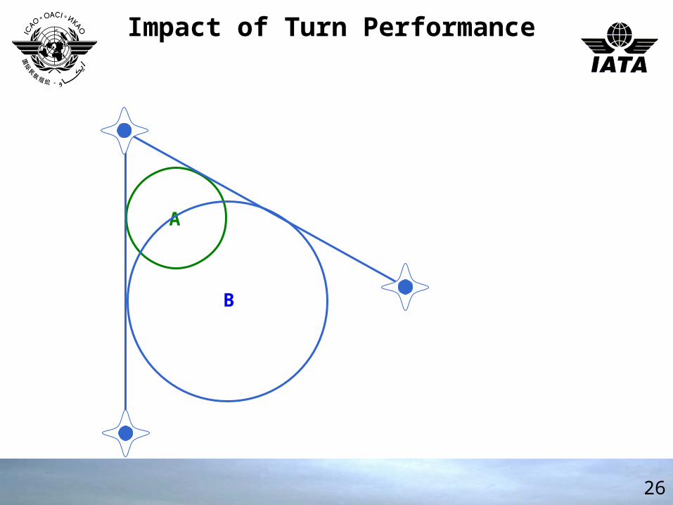
Impact of Turn Performance Impact of Turn Performance
A
B
27
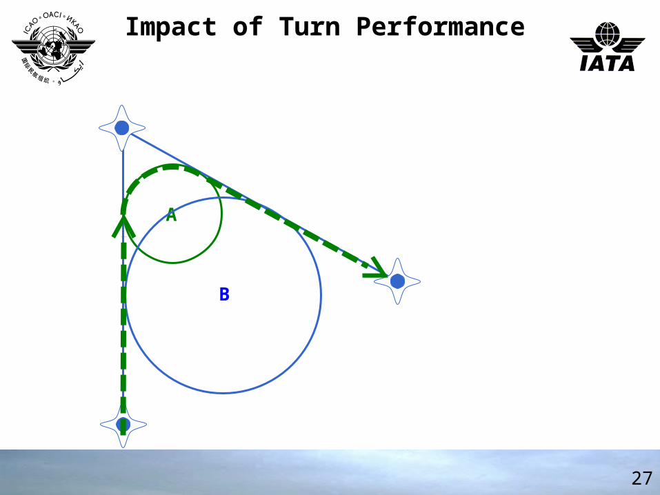
Impact of Turn Performance Impact of Turn Performance
A
B
28
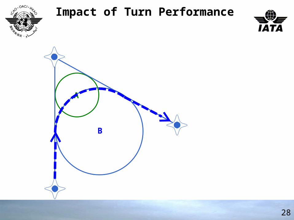
Impact of Turn Performance Impact of Turn Performance
A
B
29
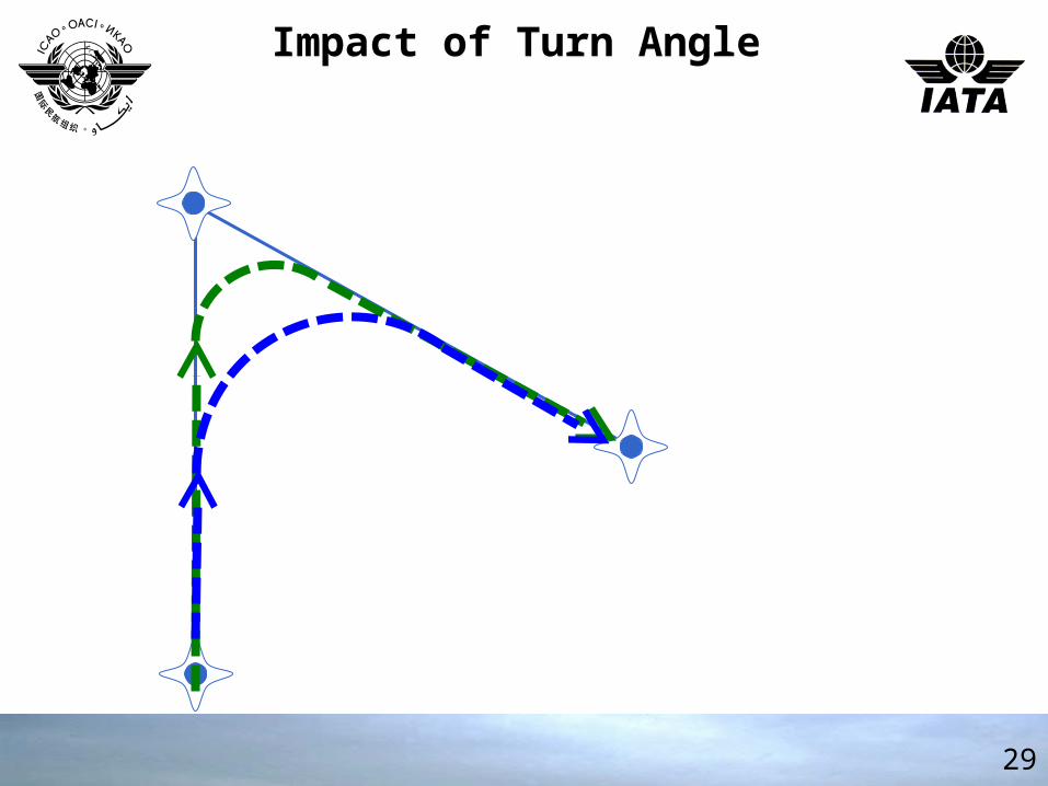
Impact of Turn Angle Impact of Turn Angle
30
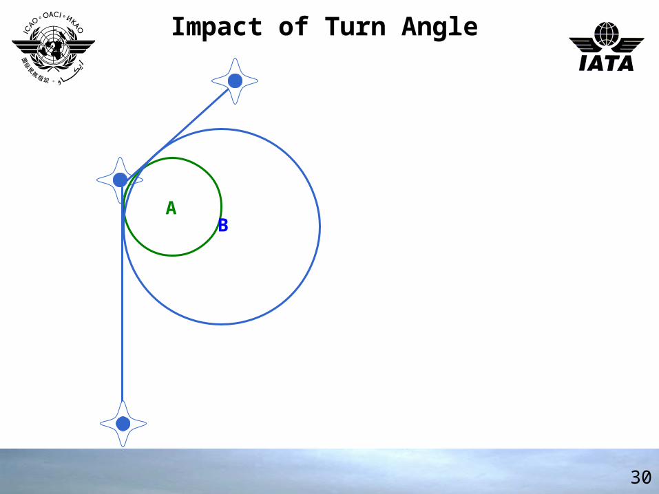
Impact of Turn Angle Impact of Turn Angle
AB
31
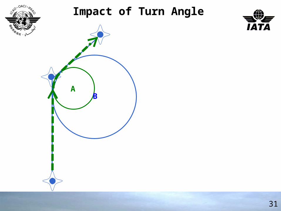
Impact of Turn Angle Impact of Turn Angle
AB
AB
32
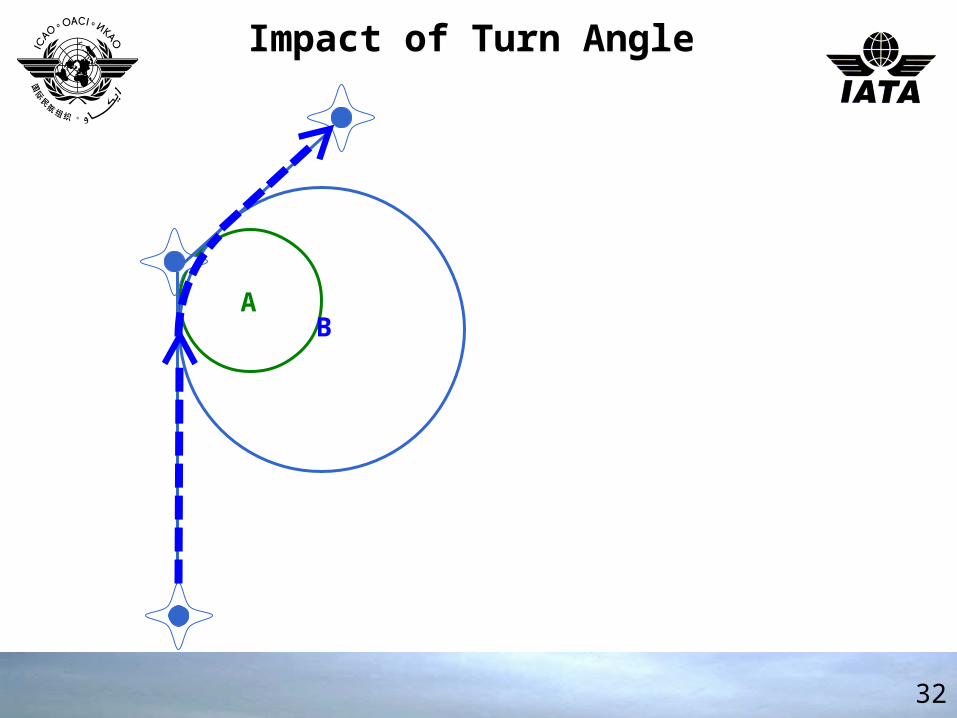
Impact of Turn Angle Impact of Turn Angle
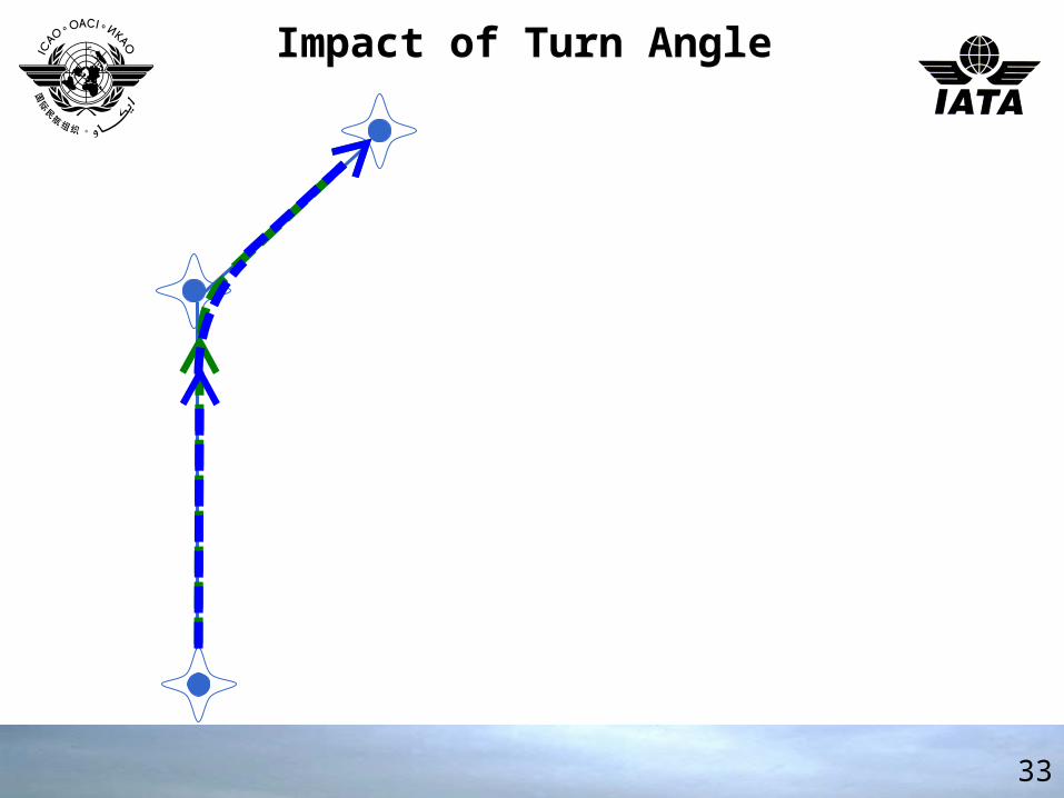
33
Impact of Turn Angle Impact of Turn Angle
34
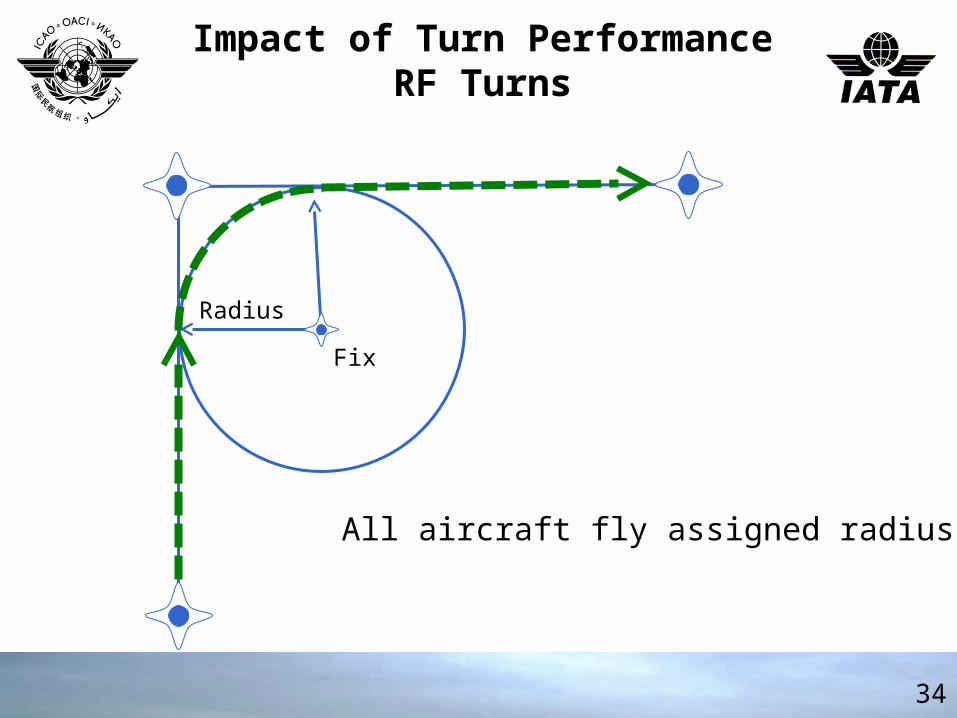
Impact of Turn PerformanceRF Turns
Impact of Turn PerformanceRF Turns
Fix
Radius
All aircraft fly assigned radius
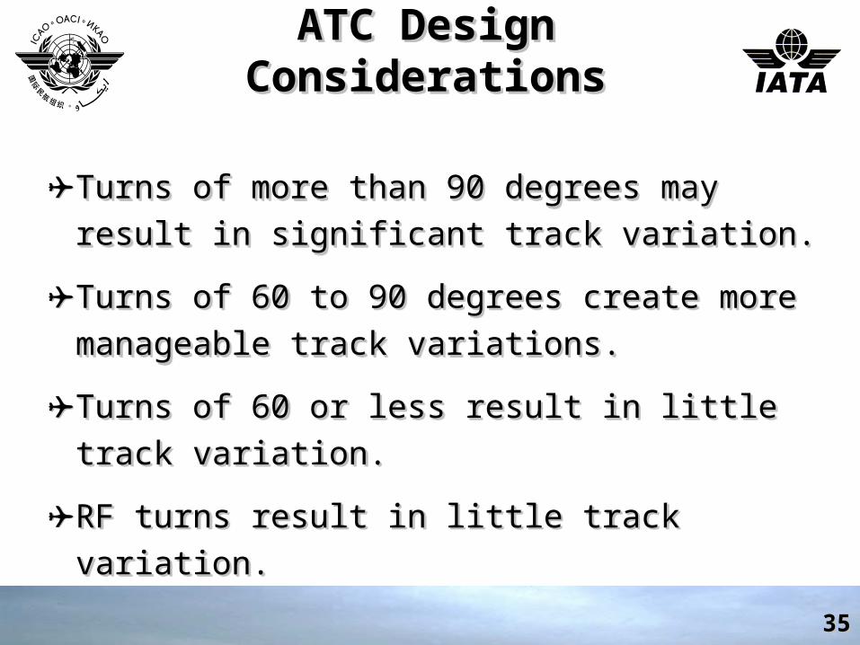
ATC Design ConsiderationsATC Design ConsiderationsATC Design ConsiderationsATC Design Considerations
✈Turns of more than 90 degrees may result in Turns of more than 90 degrees may result in significant track variation.significant track variation.
✈Turns of 60 to 90 degrees create more Turns of 60 to 90 degrees create more manageable track variations.manageable track variations.
✈Turns of 60 or less result in little track variation.Turns of 60 or less result in little track variation.
✈RF turns result in little track variation.RF turns result in little track variation.
3535
36
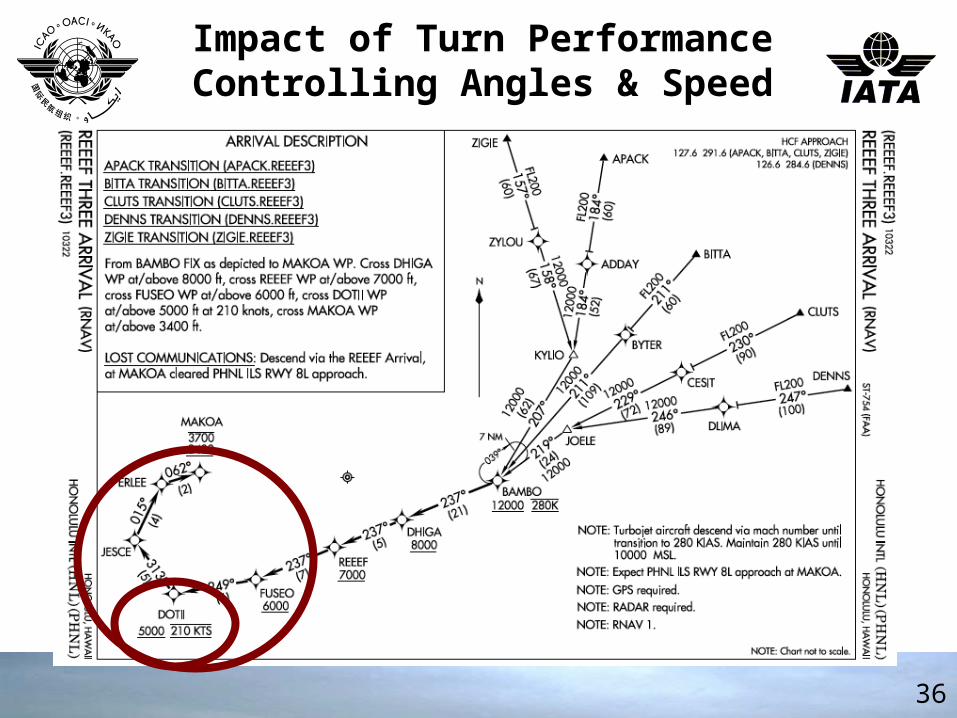
Impact of Turn PerformanceControlling Angles & SpeedImpact of Turn PerformanceControlling Angles & Speed
Speed and Altitude ConstraintsSpeed and Altitude ConstraintsSpeed and Altitude ConstraintsSpeed and Altitude Constraints
✈Speed constraints allow tighter turns and can Speed constraints allow tighter turns and can assist ATC function.assist ATC function.
✈Altitude constraints can provide separation Altitude constraints can provide separation from obstacles and other aircraft.from obstacles and other aircraft.
✈Speed constraints allow tighter turns and can Speed constraints allow tighter turns and can assist ATC function.assist ATC function.
✈Altitude constraints can provide separation Altitude constraints can provide separation from obstacles and other aircraft.from obstacles and other aircraft.
3737
Procedure Design Procedure Design ConsiderationsConsiderations
RNAV Approach TypesRNAV Approach Types
{ RNAV (GNSS) vs RNAV(RNP) }{ RNAV (GNSS) vs RNAV(RNP) }
Procedure Design Procedure Design ConsiderationsConsiderations
RNAV Approach TypesRNAV Approach Types
{ RNAV (GNSS) vs RNAV(RNP) }{ RNAV (GNSS) vs RNAV(RNP) }
3838
PBNPBNPBNPBN
3939
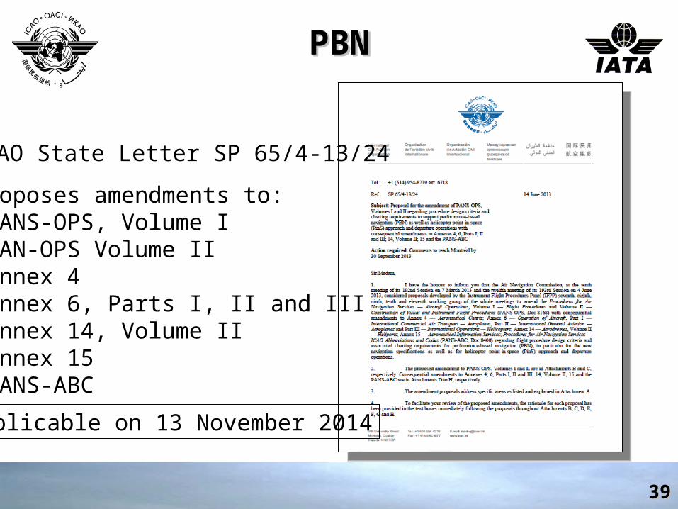
ICAO State Letter SP 65/4-13/24
Proposes amendments to:•PANS-OPS, Volume I•PAN-OPS Volume II•Annex 4•Annex 6, Parts I, II and III•Annex 14, Volume II•Annex 15•PANS-ABC
Applicable on 13 November 2014
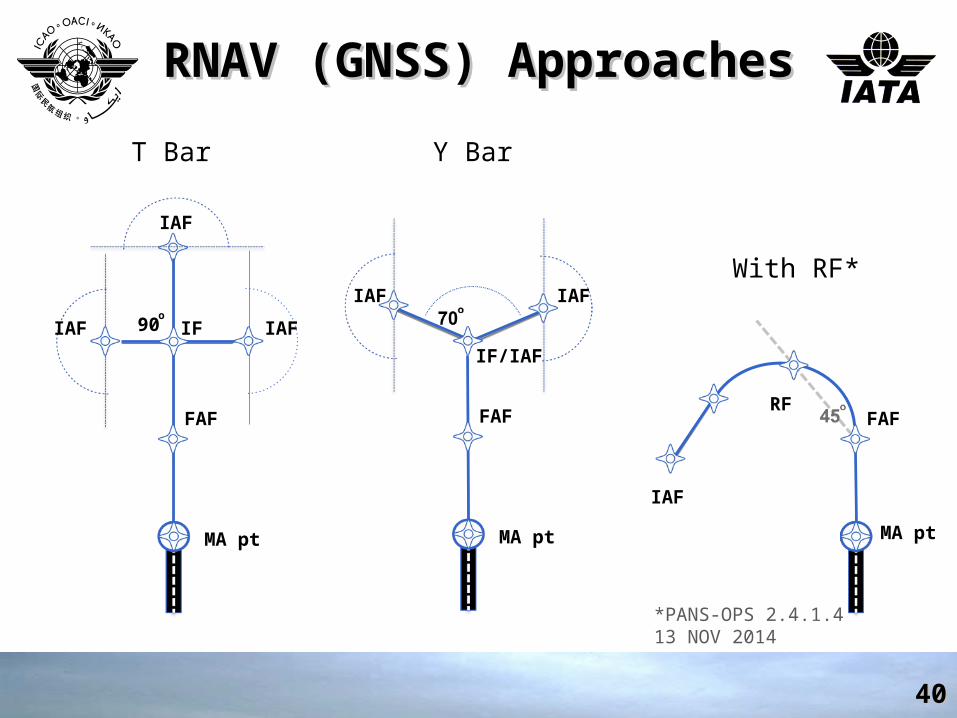
RNAV (GNSS) ApproachesRNAV (GNSS) ApproachesRNAV (GNSS) ApproachesRNAV (GNSS) Approaches
4040
IAF
IAFIAF IF
FAF
MA pt
IF/IAF
FAF
MA pt
IAFIAF
T Bar Y Bar
90o
FAF
With RF*
RF
MA pt
IAF
*PANS-OPS 2.4.1.413 NOV 2014
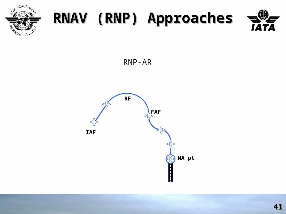
RNAV (RNP) ApproachesRNAV (RNP) ApproachesRNAV (RNP) ApproachesRNAV (RNP) Approaches
4141
FAF
RNP-AR
RF
MA pt
IAF
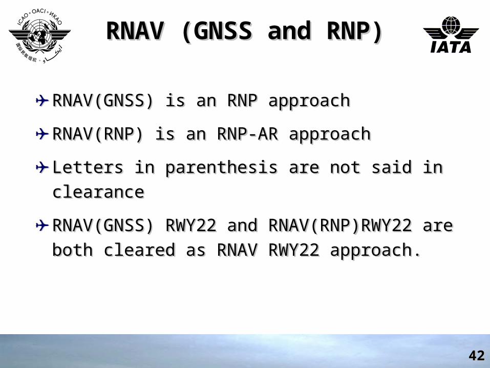
RNAV (GNSS and RNP)RNAV (GNSS and RNP)RNAV (GNSS and RNP)RNAV (GNSS and RNP)
✈ RNAV(GNSS) is an RNP approachRNAV(GNSS) is an RNP approach
✈ RNAV(RNP) is an RNP-AR approachRNAV(RNP) is an RNP-AR approach
✈ Letters in parenthesis are not said in clearanceLetters in parenthesis are not said in clearance
✈ RNAV(GNSS) RWY22 and RNAV(RNP)RWY22 are both RNAV(GNSS) RWY22 and RNAV(RNP)RWY22 are both cleared as RNAV RWY22 approach.cleared as RNAV RWY22 approach.
4242
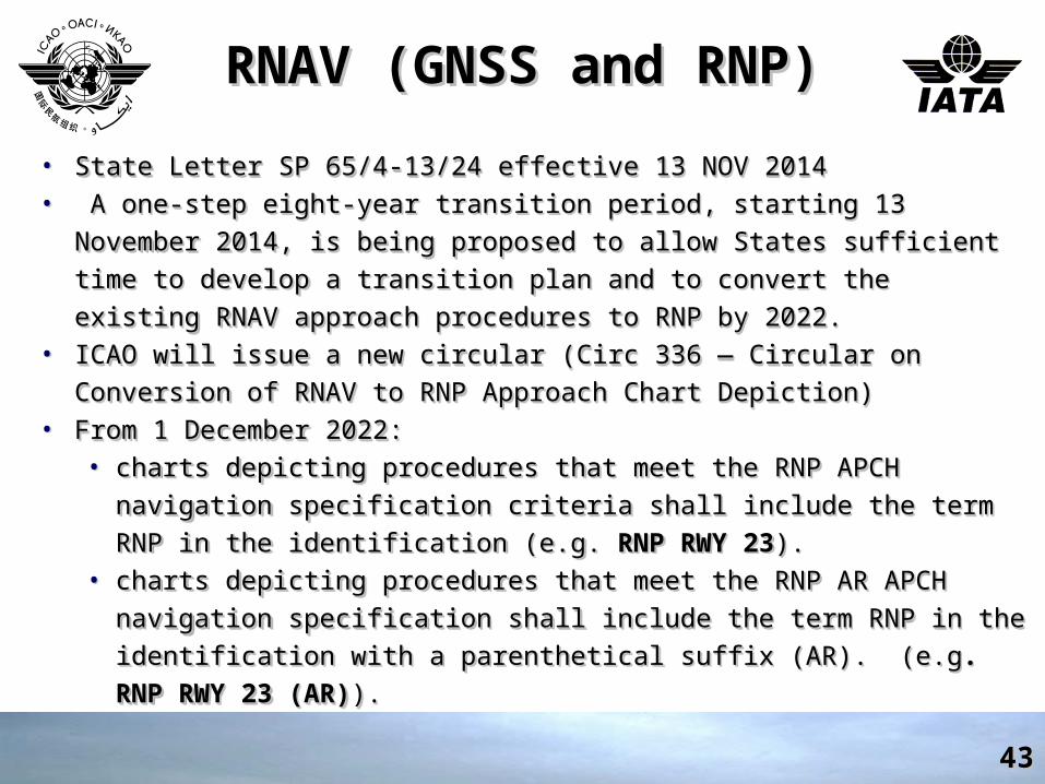
RNAV (GNSS and RNP)RNAV (GNSS and RNP)RNAV (GNSS and RNP)RNAV (GNSS and RNP)
• State Letter State Letter SP 65/4-13/24 effective 13 NOV 2014SP 65/4-13/24 effective 13 NOV 2014• A one-step eight-year transition period, starting 13 November 2014, is A one-step eight-year transition period, starting 13 November 2014, is
being proposed to allow States sufficient time to develop a transition plan being proposed to allow States sufficient time to develop a transition plan
and to convert the existing RNAV approach procedures to RNP by 2022.and to convert the existing RNAV approach procedures to RNP by 2022.• ICAO will issue a new circular (Circ 336 — Circular on Conversion of ICAO will issue a new circular (Circ 336 — Circular on Conversion of
RNAV to RNP Approach Chart Depiction)RNAV to RNP Approach Chart Depiction)• From 1 December 2022: From 1 December 2022:
• charts depicting procedures that meet the RNP APCH navigation charts depicting procedures that meet the RNP APCH navigation
specification criteria shall include the term RNP in the identification specification criteria shall include the term RNP in the identification
(e.g. (e.g. RNP RWY 23RNP RWY 23).).• charts depicting procedures that meet the RNP AR APCH navigation charts depicting procedures that meet the RNP AR APCH navigation
specification shall include the term RNP in the identification with a specification shall include the term RNP in the identification with a
parenthetical suffix (AR). (e.gparenthetical suffix (AR). (e.g. RNP RWY 23 (AR). RNP RWY 23 (AR)).).
4343
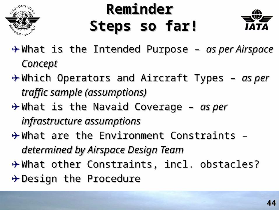
ReminderReminder Steps so far! Steps so far!
ReminderReminder Steps so far! Steps so far!
✈ What is the Intended Purpose – What is the Intended Purpose – as per Airspace Conceptas per Airspace Concept✈ Which Operators and Aircraft Types – Which Operators and Aircraft Types – as per traffic sample as per traffic sample
(assumptions)(assumptions)✈ What is the Navaid Coverage – What is the Navaid Coverage – as per infrastructure as per infrastructure
assumptionsassumptions✈ What are the Environment Constraints – What are the Environment Constraints – determined by determined by
Airspace Design TeamAirspace Design Team✈ What other Constraints, incl. obstacles?What other Constraints, incl. obstacles?✈ Design the ProcedureDesign the Procedure
4444
Thank YouThank YouThank YouThank You
4545