Embed Size (px)
Citation preview

Channels 7.6-1
October 2000 ConnDOT Drainage Manual
7.6 Roadside Channel (Type A) Design Procedure
7.6.1 General Design Considerations
The design of Type A channels shall consider flow capacity, economics, traffic safety, aesthetics,erosion control and maintenance. These considerations are usually interrelated to such an extentthat optimum conditions cannot be met for one without compromising one or more of the others; theideal being to achieve a reasonable balance.
The location, linings and cross slope of banks are important factors in safety considerations.Motorists’ safety generally improves with increasing distance between the travelway and thechannel. This distance may increase the cost of property acquisition which may be offset in part bya reduction in the cost of traffic protection. The channel may be located closer to the roadway if anerrant vehicle can negotiate the lining and cross slope and recover.
All channels are to be designed so as to minimize erosion. Erosive velocities can be reduced byflattening channel grades where uniform flow conditions exist, otherwise an appropriate channellining is to be used. To prevent erosion, all channels, ditches or swales will be lined as soon as theyare excavated.
A roadside channel is defined as an open channel usually paralleling the highway embankmentand within the limits of the highway right-of-way. It is normally trapezoidal or V-shaped in crosssection and lined with grass or a special protective lining.
The primary function of roadside channels is to collect surface runoff from the highway andareas which drain to the right-of-way and convey the accumulated runoff to acceptable outlet points.
A secondary function of a roadside channel is to drain subsurface water from the base of theroadway to prevent saturation and loss of support for the pavement or to provide a positive outlet forsubsurface drainage systems such as pipe underdrains.
The alignment, cross section and grade of roadside channels is usually constrained to a largeextent by the geometric and safety standards applicable to the project. These channels shouldaccommodate the design runoff in a manner which assures the safety of motorists and minimizesfuture maintenance, damage to adjacent properties, and adverse environmental or aesthetic effects.
7.6.2 Vertical Alignment
Grade affects both the size of the channel and the flow velocity. The flows should be keptsubcritical wherever possible so as to avoid adverse characteristics of supercritical flow.
The approximate grade of a channel is usually determined by the topography of the site. If theterrain is flat then deposition of sediment is unavoidable, the channel should be designed so that thedeposition will occur at a location accessible to maintenance.
“Vertical grade drops” or check dams, constructed of concrete walls, stones, gabions, concretecribbing, metal cribbing or treated timbers, are very useful in maintaining grades which produceacceptable velocities downstream and reduce the costs of lining a channel. These should only beused in channels not accessible to vehicles.
7.6.3 Horizontal Alignment
A straight alignment of a channel permits a simplified hydraulic design. A straight channel doesnot provide obstacles to the flow and normally will not pick up materials for later deposition atsome point downgrade. It is not usually practical to design a straight channel and have it compatiblewith the terrain or existing streams. Changes in alignment should be as gradual as the right-of-way

7.6-2 Channels
ConnDOT Drainage Manual December 2003
and terrain permit. Whenever practicable alignment changes should be made in sections with a flatgradient, particularly if flows will become supercritical on a steeper slope. This practice will reducethe force of the water against the banks and allow the use of more effective erosion controls. Whenhorizontal curvature is utilized, the effects of increased water surface on the outsides of curvesshould be considered.
7.6.4 Swales
Swales are shallow depressed areas used to drain medians, shelves with negative backslopes, andother areas where ditches are not feasible for either safety or aesthetic considerations. Grass-linedswales for the roadways generally have a longitudinal slope which conforms to the roadway gradeexcept on flat grades, where the swale grade may be steeper than the roadway grade.
7.6.5 Interceptor Channels
These channels are used to intercept runoff from adjacent areas, to collect runoff from within theproject, and to convey the runoff to suitable outlets, preferably watercourses. Interceptor channelsor ditches are divided into three categories: Top-of-slope Channels, Toe-of-Slope Channels andOutlet Channels.
The layout of Interceptor Channels should be made on a topographical map which contains theproject, location of storm drainage structures, contours, and drainage area limits.
For the purposes of payment and in accordance with the Department’s Standard Specifications, achannel shall be interpreted to mean a natural or artificial watercourse having an average width atthe bottom, after excavation, of 1.2m (4 ft) or more. A drainage ditch shall be interpreted to meanan unpaved, artificially constructed open depression having an average width of less than 1.2m (4 ft)at the bottom, after excavation, constructed for the purpose of carrying surface water.
• Top-of-Slope channels or ditches are located at the top of cut slopes for the purpose ofintercepting runoff from natural slopes inclined towards the project. They serve to reduce erosion ofthe cut slope face and to prevent debris and sediment from washing onto the project.
The following should be considered before use of a Top-of-Slope Channel:• The runoff from the contributing area can flow down the cut slope if it will not affect its
stability. The Soils and Foundations Section should be consulted to determine this. If the slopewill not be stable, then a top-of-slope channel is required.
• If the cost of additional drainage resulting from the absence of a channel exceeds the cost of thechannel, then the channel may be warranted. The fact that top-of-slope channels are farremoved from the travelway and are difficult to maintain should also be considered.
• These channels are to have a trapezoidal section with 3 horizontal to 1 vertical side slopes forgrass linings; and 2 horizontal to 1 vertical side slopes for riprap or rigid linings.
• The channel grade should be such that ponding will not occur thereby causing saturation oroverflow at the top of the slope which could result in slope failure. In areas of unstable slopesit may be necessary to intercept, and accelerate the removal of runoff with pipes. Channelscrossing highly permeable slopes may require lining with impermeable material.
• To prevent slope failure, the top of the channel nearest the slope should be located no closerthan five feet from the outer limit of the rounding created at the top of cut slopes.
• Excessively deep channel cuts to maintain constant grades should be avoided.

Channels 7.6-3
October 2000 ConnDOT Drainage Manual
• Toe-of-slope channels are located near the toe of the embankment when it is necessary toconvey water collected by storm drainage systems, swales, or runoff from terrain inclined towardthe projects, or to keep flow within the ROW until a suitable outlet is available.
These channels are to have the same cross section geometry as top-of-slope channels if theirlocation will not be hazardous to vehicular traffic. If it is determined that a trapezoidal channel willbe hazardous, then the use of guide railing must be considered. The preferred design, for bothsafety and aesthetics, would be a wide parabolic section with vertical curves to round all angles.The reduction of flow velocities through use of side, shallow channels or swales will minimizeerosion and may be possible without an appreciable increase in cost. This type of channel may befound to be more economical after considering the cost of the guide rail, lining and rights of wayrequired for alternatives.
If trapezoidal channels are used they should be located 1.5m (5 feet) from the normal toerounding of the embankment to prevent the channel from being obstructed by any natural sloughingand erosion of the adjacent embankment. The 5 foot shelf shall be on a slope of 1V:12H betweenthe toe and the top of the channel unless rights of way requirements dictate otherwise.
• Outlet channels
Outlet channels are used to convey flow from storm drainage systems and swales to awatercourse or to an area not subject to erosion.
They are usually designed with side slopes of 1V:2H. For vehicular safety, it may be necessaryto use flatter side slopes and wider trapezoidal channels, especially where outletting swales fromroadway cut sections to the toes of adjoining embankments.
Outlet channels should be located beyond the area required for vehicular recovery. They shouldbe accessible for maintenance since they may trap sediment and debris.
7.6.6 Type A Channel Design Concepts
HEC-15 provides a detailed presentation of stable channel design concepts related to the designof roadside and median channels which convey a design discharge less than 1.42 m3/s or 50 cfs.This section provides a brief summary of significant concepts.
Stable channel design concepts provide a means of evaluating and defining channelconfigurations that will perform within acceptable limits of stability. For most highway drainagechannels, bank instability and lateral migration can not be tolerated. Stability is achieved when thematerial forming the channel boundary effectively resists the erosive forces of the flow. Principlesof rigid boundary hydraulics can be applied to evaluate this type of system.
Both velocity and tractive force methods have been applied to the determination of channelstability. Permissible velocity procedures are empirical in nature, and have been used to designnumerous channels in the United States and throughout the world. However, tractive forcemethods consider actual physical processes occurring at the channel boundary and represent amore realistic model of the detachment and erosion processes.
The hydrodynamic force created by water flowing in a channel causes a shear stress on thechannel bottom. The bed material, in turn, resists this shear stress by developing a tractive force.Tractive force theory states that the flow-induced shear stress should not produce a force greaterthan the tractive resisting force of the bed material. This tractive resisting force of the bed materialcreates the permissible or critical shear stress of the bed material. In a uniform flow, the shearstress is equal to the effective component of the gravitational force acting on the body of waterparallel to the channel bottom. The average shear stress is equal to:

7.6-4 Channels
ConnDOT Drainage Manual October 2000
where: τ = average shear stress, Pa (lb/ft2)γ = unit weight of water, 9810 N/m3 (62.4 lb/ft3) (at 15.6 °C (60 °F))R = hydraulic radius, m (ft)S = average bed slope or energy slope, m/m (ft/ft)
The maximum shear stress for a straight channel occurs on the channel bed and is less than orequal to the shear stress at maximum depth. The maximum shear stress is computed as follows:
where: τd = maximum shear stress, Pa (lb/ft2)d = maximum depth of flow, m (ft)
Shear stress in channels is not uniformly distributed along the wetted perimeter of a channel. Atypical distribution of shear stress in a trapezoidal channel tends toward zero at the corners with amaximum on the bed of the channel at its centerline, and the maximum for the side slopes occursaround the lower third of the slope as illustrated in Figure 7-7.
Figure 7-7 Distribution of shear stress
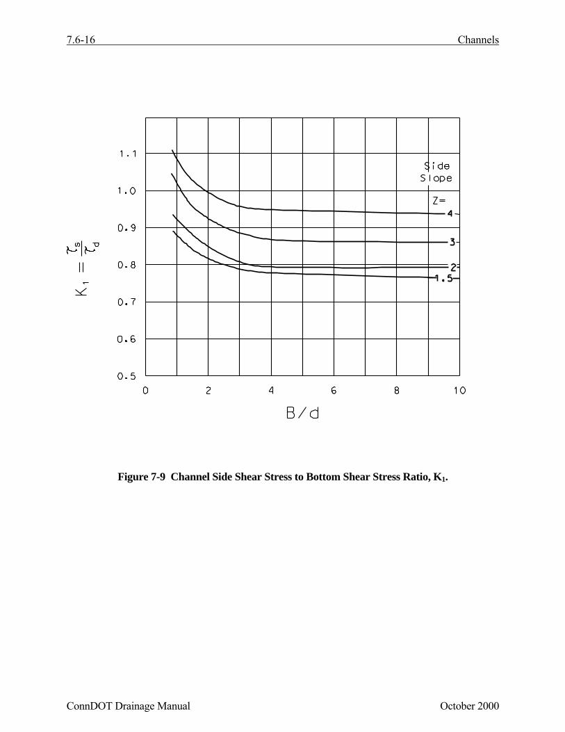
For trapezoidal channels lined with gravel or riprap having side slopes steeper than 3 horizontalto 1 vertical, side slope stability must also be considered. This analysis is performed by comparingthe tractive force ratio between side slopes and channel bottom with the ratio of shear stressesexerted on the channel sides and bottom. The ratio of shear stresses on the sides and bottom of atrapezoidal channel, K1, is given in Figure 7-9 and the tractive force ratio, K2, is given in Figure7-10. The angle of repose, θ , for different rock shapes and sizes is provided in Figure 7-11. Therequired rock size for the side slopes is found using the following equation:
S R = γτ (7.11)
S d = d γτ (7.12)

Channels 7.6-5
October 2000 ConnDOT Drainage Manual
where: D50 = the mean riprap size, m (ft)K1 = ratio of shear stresses on the sides and bottom of a trapezoidal channel (see
Figure 7-9).K2 = ratio of tractive force on the sides and bottom of a trapezoidal channel (see
Figure 7-10).
Flow around a bend in an open channel induces centrifugal forces because of the change in flowdirection. This results in a superelevation of the water surface at the outside of bends and cancause the flow to splash over the side of the channel if adequate freeboard is not provided. Thissuperelevation can be estimated by the following equation.
where: ∆d = difference in water surface elevation between the inner and outer banks of thechannel in the bend, m (ft)
V = average velocity, m/s (ft/s)T = surface width of the channel, m (ft)g = gravitational acceleration, 9.8 m/s2 (32.2 ft/s2)Rc = radius to the centerline of the channel, m (ft)
Equation 7.14 is valid for subcritical flow conditions. The elevation of the water surface at theouter channel bank will be ∆d/2 higher than the centerline water surface elevation (the averagewater surface elevation immediately before the bend) and the elevation of the water surface at theinner channel bank will be ∆d/2 lower than the centerline water surface elevation.
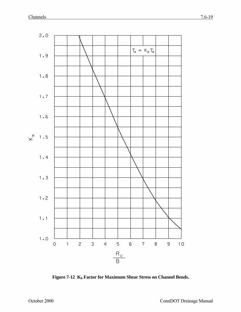
Flow around bends also creates secondary currents which impose higher shear stresses on thechannel sides and bottom compared to straight reaches. Areas of high shear stress in bends areillustrated in Figure 7-8. The maximum shear stress in a bend is a function of the ratio of channelcurvature to bottom width. This ratio increases as the bend becomes sharper and the maximumshear stress in the bend increases. The bend shear stress can be computed using the followingrelationship:
where: τb = bend shear stress, Pa (lb/ft2)Kb = function of Rc/B (see Figure 7-12)Rc = radius to the centerline of the channel, m (ft)B = bottom width of channel, m (ft)τd = maximum channel shear stress, Pa (lb/ft2)
) D( KK = ) D( bottom50
2
1sides50 (7.13)
R gT V = dc
2
∆ (7.14)
ττ dbb K = (7.15)

7.6-6 Channels
ConnDOT Drainage Manual October 2000
The increased shear stress produced by the bend persists downstream of the bend a distance Lp,as shown in Figure 7-8. This distance can be computed using the following relationship:
where: Lp = length of protection (length of increased shear stress due to the bend) downstreamof the point of tangency, m (ft)
nb = Manning's roughness in the channel bendR = hydraulic radius, m (ft)
Figure 7-8 Shear stress distribution in channel bends
nR 0.736 = L
b
6/7
p ( b
p nRL
6/7603.0= ) (7.16)

Channels 7.6-7
October 2000 ConnDOT Drainage Manual
7.6.7 Design Parameters
Parameters required for the design of roadside and median channels include dischargefrequency, channel geometry, channel slope, vegetation type, freeboard, and shear stress. Thissection provides criteria relative to the selection or computation of these design elements.
• Discharge Frequency
Roadside and median drainage channels are designed to carry the 10 year design flow. A2-year return period is used for the design of temporary linings.
Channels will be designed to convey the discharge of any connecting facility, with considerationfor possible additional flow from adjacent areas which may increase the discharge and requireadjustments in the design. The preliminary layout of the channel should be made on a topographicmap which contains the location of the project and has adequate contours to determine thecontributing drainage areas. From this map, the discharge can be estimated at appropriate pointsalong the channel. For watercourses, it is usually not necessary to compute more than one dischargeunless there are extenuating circumstances. Additional information on design discharge can befound in other sections of this chapter.
• Channel Geometry
Channel side slopes for triangular or trapezoidal channels cannot exceed the angle of repose ofthe soil and/or lining material, and should generally be 3 horizontal to 1 vertical or flatter. In areaswhere traffic safety may be of concern, channel side slopes should be 4 horizontal to 1 vertical orflatter.
Design of roadside and median channels should be integrated with the highway geometric andpavement design to insure proper consideration of safety and pavement drainage needs.
• Channel Slope
Channel bottom slopes are generally dictated by the road profile or other constraints. However,if channel stability conditions warrant, it may be feasible to adjust the channel gradient slightly toachieve a more stable condition. Channel gradients greater than two percent may require the use offlexible linings to maintain stability. Most flexible lining materials are suitable for protectingchannel gradients of up to 10 percent, with the exception of some grasses. Linings, such as riprapand wire-enclosed riprap are more suitable for protecting very steep channels with gradients inexcess of 10 percent. Rigid linings, such as concrete paving, are highly susceptible to failure fromstructural instability due to such occurrences as overtopping, freeze thaw cycles, swelling, andexcessive soil pore water pressure.
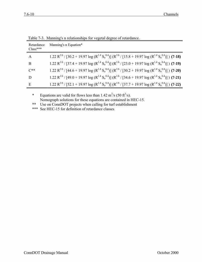
• Roughness Coefficient (Manning’s n values)
The selection of an appropriate Manning's n value for design purposes is often based onobservation and experience. Manning's n values are also known to vary with flow depth. Table 7-2provides a tabulation of Manning's n values for various channel lining materials. Manning'sroughness coefficient for vegetative and other linings vary significantly depending on the amountof submergence. The classification of vegetal covers by degree of retardance is provided in
7.6-8 Channels
ConnDOT Drainage Manual October 2000
HEC-15. Table 7-3 provides a list of Manning's n relationships for five classes of vegetationdefined by their degree of retardance.
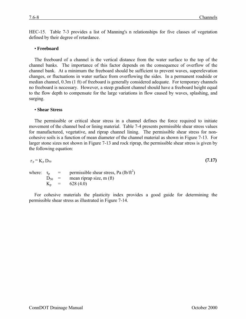
• Freeboard
The freeboard of a channel is the vertical distance from the water surface to the top of thechannel banks. The importance of this factor depends on the consequence of overflow of thechannel bank. At a minimum the freeboard should be sufficient to prevent waves, superelevationchanges, or fluctuations in water surface from overflowing the sides. In a permanent roadside ormedian channel, 0.3m (1 ft) of freeboard is generally considered adequate. For temporary channelsno freeboard is necessary. However, a steep gradient channel should have a freeboard height equalto the flow depth to compensate for the large variations in flow caused by waves, splashing, andsurging.
• Shear Stress
The permissible or critical shear stress in a channel defines the force required to initiatemovement of the channel bed or lining material. Table 7-4 presents permissible shear stress valuesfor manufactured, vegetative, and riprap channel lining. The permissible shear stress for non-cohesive soils is a function of mean diameter of the channel material as shown in Figure 7-13. Forlarger stone sizes not shown in Figure 7-13 and rock riprap, the permissible shear stress is given bythe following equation:
where: τp = permissible shear stress, Pa (lb/ft2)D50 = mean riprap size, m (ft)Kp = 628 (4.0)
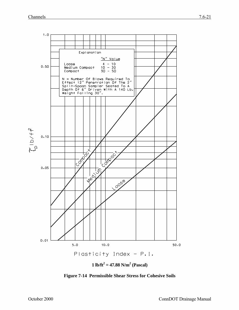
For cohesive materials the plasticity index provides a good guide for determining thepermissible shear stress as illustrated in Figure 7-14.
D K = 50ppτ (7.17)

Channels 7.6-9
October 2000 ConnDOT Drainage Manual
Table 7-2. Manning's roughness coefficients for Roadside and Median Channels. *
n - Value for Given Depth Ranges
Lining
Category
ConnDOT
Designations
Lining Type 0-0.15 m(0-0.5 ft)
0.15-0.60 m(0.5-2.0 ft)
>0.60 m(>2.0 ft)
Rigid ConcreteGrouted RiprapStone MasonrySoil CementAsphalt
0.0150.0400.0420.0250.018
0.0130.0300.0320.0220.016
0.0130.0280.0300.0200.016
Unlined Bare SoilRock Cut
0.0230.045
0.0200.035
0.0200.025
Type E Woven Paper NetJute Net
0.0160.028
0.0150.022
0.0150.019
Type F Fiberglass Roving 0.028 0.021 0.019Type G Straw with Net
Curled Wood Mat0.0650.066
0.0330.035
0.0250.028
Erosion ControlMatting**
(Temporary orPermanent)
Type H Synthetic Mat 0.036 0.025 0.021
Gravel RiprapSpecial
25 mm (1 in) D5050 mm (2 in) D50
0.0440.066
0.0330.041
0.0300.034
Rock Riprap Modified
Intermediate
Standard
125 mm (5 in) D50
150 mm (6 in) D50
200 mm (8 in) D50300 mm (12 in) D50
380 mm (15 in) D50
0.0950.104------
0.0620.0690.0720.078--
0.0350.0350.0370.0400.042
NOTE: Values listed are representative values for the respective depth ranges. Manning'sroughness coefficients, n, vary with the flow depth.
* Table reproduced from HEC-15** See Section 7.6.8
7.6-10 Channels
ConnDOT Drainage Manual October 2000
Table 7-3. Manning's n relationships for vegetal degree of retardance.
RetardanceClass***
Manning's n Equation*
A 1.22 R1/6 / [30.2 + 19.97 log (R1.4 So0.4)] (R1/6 / [15.8 + 19.97 log (R1.4 So
0.4)] ) (7-18)
B 1.22 R1/6 / [37.4 + 19.97 log (R1.4 So0.4)] (R1/6 / [23.0 + 19.97 log (R1.4 So
0.4)] ) (7-19)
C** 1.22 R1/6 / [44.6 + 19.97 log (R1.4 So0.4)] (R1/6 / [30.2 + 19.97 log (R1.4 So
0.4)] ) (7-20)
D 1.22 R1/6 / [49.0 + 19.97 log (R1.4 So0.4)] (R1/6 / [34.6 + 19.97 log (R1.4 So
0.4)] ) (7-21)
E 1.22 R1/6 / [52.1 + 19.97 log (R1.4 So0.4)] (R1/6 / [37.7 + 19.97 log (R1.4 So
0.4)] ) (7-22)
* Equations are valid for flows less than 1.42 m3/s (50 ft3/s).Nomograph solutions for these equations are contained in HEC-15.
** Use on ConnDOT projects when calling for turf establishment*** See HEC-15 for definition of retardance classes

Channels 7.6-11
December 2003 ConnDOT Drainage Manual
Table 7-4 Permissible Shear Stresses for Lining Materials*
Permissible Unit Shear Stress
Lining Category ConnDOTDesignations
Lining Type Pa lb/ft2
Type E Woven Paper NetJute Net
7.221.5
0.150.45
Type FFiberglass Roving: Single Double
28.740.7
0.600.85
Type G Straw with NetCurled Wood Mat
69.474.2
1.451.55
Erosion ControlMatting**
Type H Synthetic Mat 95.8 2.00
Vegetative
TurfEstablishment
Class AClass BClass C-Use for DOTprojects
177.2100.647.9
3.702.101.00
Class DClass E
28.716.8
0.600.35
Gravel RiprapSpecial
25 mm (1 in)50 mm (2 in)
15.831.6
0.330.67
Rock Riprap Modified
Intermediate
Standard
125 mm (5 in)150 mm (6 in)200 mm (8 in)300 mm (12 in)380 mm (15 in)
79.895.8
127.7191.5239.3
1.682.002.684.005.00
Bare Soil Non-cohesiveCohesive
Figure 7-13Figure 7-14
* Reproduced from HEC-15** See Section 7.6.8
7.6.8 Erosion Control Matting
Erosion control matting is evaluated by the Department for use in eight Types (A-H), groupedinto two Classes. Types A through D are included in Class 1 and are designated as SlopeProtection. This classification is based upon steepness of the slope and soil type. The purpose ofClass 1 matting is to protect the seedbed from loss of soil, and promote the establishment of awarm-season, perennial vegetative cover.

7.6-12 Channels
ConnDOT Drainage Manual December 2003
Types E through H are included in Class 2 and are designated as Flexible Channel LinerProtection. This classification is based upon the permissible shear stress of the material. Thepurpose of Class 2 matting is to protect the geometry of a channel from loss of soil, and to promotethe establishment of a warm-season, perennial vegetative cover. Class 2 Types are designatedaccording to the shear stress limits shown in Table 7-5. The shear stress ranges are based on valuespublished in HEC-15.
Table 7-5 Erosion Control Matting (Class 2) Shear Stress Ranges
Matting Type Permissible Shear Stress – Pa (lb/ft2)E < 25 (<0.5)F 25 to < 50 (0.5 to <1.0)G 50 to < 100 (1.0 to <2.0)H > 100 (>2.0)
Products approved by the Department for use as erosion control matting on State projects areplaced on an Approved Products List. This list is updated annually and distributed by theDepartment’s Office of Research and Materials. Products listed by brand or trade name on theApproved Products List have demonstrated their ability to meet or exceed the Department’sminimum performance standards by independent testing conducted at facilities such as the TexasDepartment of Transportation/Texas Transportation Institute Hydraulics and Erosion ControlLaboratory.
The drainage designer is primarily concerned with Class 2 matting materials for use in theconstruction of roadside channels. Erosion control matting in channel lining applications can betemporary (bio- or photodegradable) or permanent (non-bio- or non-photodegradable). Types E, Fand G matting are generally temporary and include but are not limited to the following materials:(E) Woven Paper Net, Jute Net and (F) Single or Double Fiberglass Roving and (G) Straw with Net,Curled Wood Mat. Type H matting is generally composed of synthetic material, is permanent and iscommonly used for turf reinforcement. If the channel design requires the use of a permanentmatting, the matting should be noted as permanent on the project plans.
The designer should be aware that it is the contractor’s option as to which product he orshe actually uses on a project, provided that the product used is on the Approved ProductsList for that application. Appropriate judgement should be reflected in the engineeringcalculations when selecting the Type of Matting (E, F, G or H) to be specified on the projectplans.
See Appendix B for additional guidance regarding the use of erosion control matting invegetative (grass) lined swales.

Channels 7.6-13
October 2000 ConnDOT Drainage Manual
7.6.9 Design Procedure for Roadside Ditches, Swales, and Channels (Type A)
This section presents a generalized procedure for the design of roadside and median channels.Although each project will be unique, the design steps outlined below will normally be applicable.
Step 1. Establish a Preliminary Drainage Plan
For proposed median or roadside channels, the following preliminary action should be taken:
A. Prepare existing and proposed plan and profile of the proposed channels. Include anyconstraints on design such as highway and road locations, culverts, utilities, etc.
B. Determine and plot on the plan the locations of natural basin divides and channel outletpoints.
C. Collect any available site data such as soil types and topographic information.
Step 2. Obtain or Establish Cross Section Data
Establish preliminary cross section geometric parameters and controlling physical featuresconsidering the following guides:
A. Adequate channel depth should be provided to drain the pavement subbase and minimizefreeze-thaw.
B. Channel side slopes based on geometric design criteria including safety, economics, soil,aesthetics, and access should be chosen.
Step 3. Determine Initial Channel Grades
Plot initial grades on the plan and profile. Note that slopes on roadside channels in cuts areusually controlled by highway grades. Use the following guides when establishing initialgrades:
A. Provide a channel slope with a minimum 0.5% grade to minimize ponding and sedimentaccumulation.
B. Where possible, avoid features which may influence or restrict grade, such as utilitystructures.
Step 4. Check flow Capacities and Adjust Sections as Necessary
A. Compute the design discharge at the downstream end of channel segments.
B. Set preliminary values for channel size, roughness, and slope, based on long term conditionsand considering maintenance.
C. Determine the maximum allowable depth of channel including freeboard.

7.6-14 Channels
ConnDOT Drainage Manual October 2000
D. Check the flow capacity using Manning's equation
E. If the capacity is not adequate, possible considerations for increasing the capacity areprovided below.
• increase bottom width• make channel side slopes flatter• make channel slope steeper• provide smoother channel lining• install drop inlets and a parallel storm drain pipe beneath the channel to supplement
channel capacity
Step 5. Determine Channel Protection Needed
A. Select a lining and determine the permissible shear stress from Table 7-4. For detailedinformation related to lining performance, see HEC-15.
B. Estimate the flow depth and choose an initial Manning's n value from Table 7-2 or Table7-3.
C. Calculate the normal flow depth at design discharge using Manning's equation and comparewith the estimated depth. If the flow depth is acceptable, continue with the designprocedure. If the depth is not acceptable, repeat steps 5B and 5C.
D. Compute the maximum shear stress at normal depth using equation 7.12.
E. If the maximum shear stress (step 5D) is less than the permissible shear stress (step 5A),then the lining is acceptable. Otherwise consider the following options:
• choose a more resistant lining• use concrete, gabions, or other more rigid lining either as full lining or composite
(keeping in consideration the possible deficiencies of rigid linings)• decrease channel slope• decrease slope in combination with drop structures• increase channel width and/or flatten side slopes
If the maximum shear stress is excessively less than the permissible shear stress, the liningmaterial may be redesigned to provide a more comparable lining material.
F. For trapezoidal channels lined with gravel or riprap having side slopes steeper than 3horizontal to 1 vertical, use equation 7-13 and Figures 7-9 and 7-10 to evaluate side slopestability.
G. For flow around bends, use equation 7.15 and Figure 7-12 to evaluate lining stability.
H. When channel gradients approach 10 percent, compare results obtained above with steepslope procedures in HEC-15.

Channels 7.6-15
December 2003 ConnDOT Drainage Manual
I. For composite linings use procedures in HEC-15.
J. If a grass lining is designated without a permanent erosion control matting, then a temporaryprotective lining will be designed using a 2 year frequency storm repeating the above steps.See Appendix B for additional guidance regarding the use of erosion control matting invegetative (grass) lined swales.
Step 6. Check Channel Transitions and End of Reach Conditions
Channel transition include locations where there are changes in cross section, slope, discharge,and/or roughness. At these locations, the gradually varying flow assumption may be violated,and a more detailed hydraulic evaluation may be required.
A. Identify transition locations.
B. Review hydraulic conditions upstream and downstream of the transition (flow area, depth,and velocity). If significant changes in these parameters are observed, perform additionalhydraulic evaluations to determine flow conditions in the vicinity of the transition. SeeHEC-15.
C. Provide for gradual channel transitions to minimize the possibility for sudden changes inhydraulic conditions at channel transitions.
Step 7. Analyze Outlet Points and Downstream Effects
A. Identify any adverse impacts to downstream properties which may result from one of thefollowing at the channel outlets:
• increase or decrease in peak discharge• increase in flow velocity• confinement of sheet flow• change in outlet water quality• diversion of flow from another watershed
B. Mitigate any adverse impacts identified in 7A. Possibilities in order relative to aboveimpacts include:
• enlarge outlet channel and/or install control structures to provide detention of increasedrunoff in channel
• install velocity control or energy dissipation structure• increase capacity and/or improve lining of downstream channel• install sophisticated weirs or other outlet devices to redistribute concentrated channel
flow• eliminate diversions which result in downstream damage and which cannot be mitigated
in a less expensive fashion
To obtain the optimum roadside channel system design, it may be necessary to make several trialsof the above procedure before a final design is achieved.
7.6-16 Channels
ConnDOT Drainage Manual October 2000
Figure 7-9 Channel Side Shear Stress to Bottom Shear Stress Ratio, K1.

Channels 7.6-17
October 2000 ConnDOT Drainage Manual
Figure 7-10 Tractive Force Ratio, K2
θ
- Φ Deg.
Φ−= 2
2
2 1SinSinK θ

7.6-18 Channels
ConnDOT Drainage Manual October 2000
Figure 7-11 Angle of Repose of Riprap in Terms of Mean Size and Shape of Stone
Φ -
Channels 7.6-19
October 2000 ConnDOT Drainage Manual
Figure 7-12 Kb Factor for Maximum Shear Stress on Channel Bends.

7.6-20 Channels
ConnDOT Drainage Manual October 2000
1 lb/ft2 = 47.88 N/m2 (Pascal)
Figure 7-13 Permissible Shear Stress for Non-cohesive Soils
Channels 7.6-21
October 2000 ConnDOT Drainage Manual
1 lb/ft2 = 47.88 N/m2 (Pascal)
Figure 7-14 Permissible Shear Stress for Cohesive Soils

7.6-22 Channels
ConnDOT Drainage Manual October 2000
7.6.10 Documentation (Type A, Channel)
The following items shall be included in the documentation file (see Chapter 1, Section 1.6). Theintent is not to limit data to only those items listed, but rather establish a minimum requirementconsistent with the channel design procedures as outlined in this chapter. If circumstances are suchthat the design is prepared other than the normal procedures or is governed by factors other thanhydrologic/hydraulic factors, then a narrative summary detailing the design basis shall appear withthe other data:
The following items shall be included in the documentation file:
• Computations based on Section 7.6.9• Channel configuration• Complete watershed map• Prepare report and file with background information