Embed Size (px)
Citation preview

SPECIFICATION
205-25
110kV 200MVA Single Circuit Overhead
Lines
16 May 2016
UNCONTROLLED W
HEN PRIN
TED

205-25 Issue 1 – May 2016
Page ii
Specification 205-25
110kV 200MVA Single Circuit Overhead Lines Table of Contents
1 Foreword ............................................................................................................. 1
2 General ................................................................................................................ 2
Scope ............................................................................................................. 2 2.1
Standards ....................................................................................................... 2 2.2
2.2.1 International Standards ............................................................................ 2
2.2.2 British Standards ...................................................................................... 2
2.2.3 ENA Standards ......................................................................................... 4
2.2.4 Legislation ................................................................................................ 4
2.2.5 NIE Standards .......................................................................................... 5
3 Definitions ............................................................................................................ 5
4 Design Data ......................................................................................................... 6
System Requirements .................................................................................... 6 4.1
Conductor Tension Load Cases ..................................................................... 7 4.2
Combined Wind and Ice ................................................................................. 7 4.3
Load Cases .................................................................................................... 7 4.4
Partial Factors for Actions .............................................................................. 8 4.5
Partial Strength Factors for Overhead Line Components ............................... 8 4.6
Conductor Parameters ................................................................................... 9 4.7
Earthwire Parameters ..................................................................................... 9 4.8
Intermediate Supports .................................................................................. 10 4.9
Angle Supports .......................................................................................... 10 4.10
Terminal Supports ...................................................................................... 10 4.11
5 Materials ............................................................................................................ 11
Conductor Sub-system ................................................................................. 11 5.1
Insulator Sub-system .................................................................................... 11 5.2
Earthwire Sub-system .................................................................................. 11 5.3
Tower Steelwork ........................................................................................... 12 5.4
Wood Poles .................................................................................................. 12 5.5
Support Ancillaries ....................................................................................... 12 5.6
6 Line Design ........................................................................................................ 13
Span Lengths Intermediate .......................................................................... 13 6.1
UNCONTROLLED W
HEN PRIN
TED

205-25 Issue 1 – May 2016
Page iii
6.1.1 Support Structures.................................................................................. 13
6.1.2 Angle and Terminal Support Structures .................................................. 13
Angle of Deviation ........................................................................................ 14 6.2
Minimum Conductor Weight at Intermediate Support Structures .................. 14 6.3
Vertical Conductor load ................................................................................ 14 6.4
Stringing Basis ............................................................................................. 14 6.5
Use of back stays ......................................................................................... 16 6.6
Internal Clearances ...................................................................................... 16 6.7
External Clearances ..................................................................................... 16 6.8
Downleads.................................................................................................... 17 6.9
Geotechnical Parameters........................................................................... 17 6.10
Foundations ............................................................................................... 17 6.11
6.11.1 Intermediate support foundations ......................................................... 17
6.11.2 Foundation Installation at Intermediate Supports ................................. 17
6.11.3 Angle and Terminal Tower Foundations ............................................... 18
Earthing...................................................................................................... 18 6.12
Operations and Maintenance ..................................................................... 18 6.13
UNCONTROLLED W
HEN PRIN
TED

205-25 Issue 1 – May 2016
1
1 Foreword
This Specification is issued with the approval of the assets Manager, Asset Management. This is the first version of the document to be issued.
This Specification details the design of a 110kV single circuit overhead line with a route rating of 200MVA.
UNCONTROLLED W
HEN PRIN
TED

205-25 Issue 1 – May 2016
2
2 General
Scope 2.1
This specification is based on a three phase 110 kV single circuit overhead line. The phase conductor will be 400 mm² (Aluminium Conductor Steel-Reinforced) ACSR Zebra. A twin earthwire system will be installed consisting of a Horse equivalent (Optical Ground Wire) OPGW (24 fibre) and 70 mm² ACSR Horse earthwire.
Support structures include the use of wooden portal frame ‘H’ structures for the intermediate locations and modified (strengthened) L4 (m) SF60 structures for the angle and terminal tower locations. This specification applies to line below 500m.
The specification is intended to allow competent overhead line designers to plan a feasible overhead line route. Detailed design checks must be undertaken on the final arrangements to ensure the suitability of the design (taking into account site specific features) prior to commencement of any construction activities.
Standards 2.2
2.2.1 International Standards
Reference No. Description Rev/Date
IEC 60815-1
Selection and dimensioning of high voltage insulators intended for use in polluted conditions – Part 1: Definitions, information and general principles
2008
IEC 60815-2 Selection and dimensioning of high voltage insulators intended for use in polluted conditions – Part 2: Ceramic and glass insulator for AC systems
2008
IEC 60815-3 Selection and dimensioning of high voltage insulators intended for use in polluted conditions – Part 3: Polymer insulators for AC systems
2008
2.2.2 British Standards
Reference No. Description Rev/Date
BS 215
Aluminium Conductors and Aluminium Conductors, Steel-reinforced, for Overhead Power Transmission. Part 2 Aluminium Conductors, Steel-reinforced
1970
BS 1990-1 Wood Poles for Overhead Power and Telecommunication Lines
1984
BS 3288-1 Insulator and Conductor Fittings for Overhead Power Lines
2014
UNCONTROLLED W
HEN PRIN
TED

205-25 Issue 1 – May 2016
3
BS 5950-1 * Structural use of steelwork in building 2000
BS 8110-1 * Structural Use of concrete 1997
BS 10025-2 Hot rolled products of structural steels 2004
BS EN 50182 Conductors for Overhead Lines -Round wire concentric lay overhead electrical stranded conductors
2001
BS EN 50341-1 Overhead electrical lines exceeding AC 1kV – Part 1 General requirements – Common Specification
2012
BS EN 50341-2 Overhead electrical lines exceeding AC 45kV – Part 2 Index of National Normative Aspects
2001
BS EN 50341-2-9
Overhead electrical lines exceeding AC 1kV – Part 9 National Normative Aspect for Great Britain and Northern Ireland
2015
BS EN 60071 Insulation Co-ordination. Part 1: Definitions, principles and rules.
2010
BS EN 60383-1
Insulators for overhead lines with nominal voltages above 1kV. Part 1: Ceramic or glass insulator units for AC systems – Definitions, test methods and acceptance criteria
1998
BS EN 60383-2
Insulators for overhead lines with nominal voltages above 1000V. Part 2: Insulator strings and insulator sets for AC systems – Definitions, test methods and acceptance criteria
1995
BS EN 61109
Insulators for overhead lines – Composite suspension and tension insulators for AC systems with a nominal voltage greater than 1000V – Definitions, test methods and acceptance criteria
2008
BS EN 61284 Overhead lines – Requirements and tests for fittings
1998
BS EN 61466-1 Composite string insulator units for overhead lines with a nominal voltage greater than 1000V. Part 1 Standard strength classes and end fittings
1999
BS EN 61466-2 Composite string insulator units for overhead lines with a nominal voltage greater than 1000V. Part 2 Dimensions and electrical characteristics
1997
BS EN 61467 Insulators for overhead lines – Insulators strings and sets for lines with a nominal voltage greater than 1000V – AC Power arc tests
2008
UNCONTROLLED W
HEN PRIN
TED

205-25 Issue 1 – May 2016
4
BS EN 61897 Overhead lines-Requirements and tests for Stockbridge type Aeolian vibration dampers.
1999
BS EN ISO 1461 Hot dip galvanizing coatings on fabricated iron and steel articles
2009
* British Standards as per original framework agreement with NIE Networks
2.2.3 ENA Standards
Reference No. Description Rev/Date
ENA TS 43-7 132kV Steel tower transmission lines Specification L4 (m)
4
ENA TS 43-8 Overhead Line Clearances 4
ENA 43-50 Specification for Single Circuit Overhead Lines on Wood Poles for use at 132 kV
2/2012
ENA TS 43-90 Anti-climbing Devices for H.V. lines up to and including 400kV
6
ENA TS 43-92 Conductor Terminations, Joints and Insulator Binds for Overhead Lines up to and Including 132 kV
4
ENA TS 43-93 Line Insulators 4
ENA TS 43-100 Conductor tensions and sags 1
ENA TS 43-125 Design Guide and technical specification for overhead lines above 45kV
1
ENA TS 43-126 Fittings for Overhead line Optical Cables. Part 1 OPGW
1
Engineering Recommendation L.38
Protective Greasing of PVC-covered Copper and Bare and PVC-covered Aluminium-based Overhead Line Conductors
2.2.4 Legislation
Reference No. Description Rev/Date
The Electricity Safety, Quality and Continuity Regulations 2012
2012
- The Electricity (Northern Ireland) Order 1992 1992
- Overhead Lines (Exemption) Regulations (Northern Ireland)
1992
2001/90/EC Creosote Directive 2001
UNCONTROLLED W
HEN PRIN
TED

205-25 Issue 1 – May 2016
5
2.2.5 NIE Standards
Reference No. Description Rev/Date
6-025 NIE Networks Clearance Policy
206-05 NIE Networks ACSR Specification 206-05
206-16 NIE Networks Specification for Wood Poles
206-15 NIE Networks Baulk Specification
206-35 NIE Networks Specification for High Voltage Cap & Pin Insulators
NIE Networks Transmission Overhead Lines Manual
16303724/0114 200MVA Operations and Maintenance Manual B
16303725/0116 Intermediate H Pole structure and Foundation Design Guide
D
16303724/0121 Structure Design Specification C
3 Definitions
For the purpose of this specification the following definitions shall apply:
Intermediate Support - A support in a straight run of a line on which the conductors are
supported on line insulator sets.
Angle Support - A support at which the conductors are made off on either side of the cross-
arm on tension insulator sets.
Terminal Support - A support at which a line terminates. Full line tension insulator sets are
installed on the line side of this support.
Span - The horizontal distance between adjacent supports.
Wind Span - The wind loading span associated with any support is half the sum of the spans adjacent to the support.
Factor of Safety - The ratio, allowed for in the design of the overhead line, between the ultimate stress in a component and the safe permissible stress in it.
Conductor Downpull - The downward vertical load imposed by the conductor at a support resulting from the gradients to the adjacent structure/pole tops.
Conductor Uplift - The upward vertical load imposed by the conductor at a support resulting from the gradients to the adjacent structure/pole tops.
UNCONTROLLED W
HEN PRIN
TED
205-25 Issue 1 – May 2016
6
Weight Span - The sum of the distances, either side of a support, to the real or apparent
invert points of the catenaries of the adjacent spans.
Basic Span - The span length adopted for sag/tension calculations.
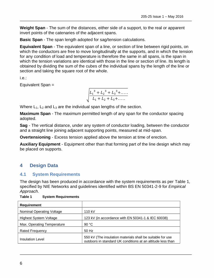
Equivalent Span - The equivalent span of a line, or section of line between rigid points, on which the conductors are free to move longitudinally at the supports, and in which the tension for any condition of load and temperature is therefore the same in all spans, is the span in which the tension variations are identical with those in the line or section of line. Its length is obtained by dividing the sum of the cubes of the individual spans by the length of the line or section and taking the square root of the whole.
i.e.:
Equivalent Span =
√
Where L1, L2 and L3 are the individual span lengths of the section.
Maximum Span - The maximum permitted length of any span for the conductor spacing
adopted.
Sag - The vertical distance, under any system of conductor loading, between the conductor
and a straight line joining adjacent supporting points, measured at mid-span.
Overtensioning - Excess tension applied above the tension at time of erection.
Auxiliary Equipment - Equipment other than that forming part of the line design which may be placed on supports.
4 Design Data
System Requirements 4.1
The design has been produced in accordance with the system requirements as per Table 1, specified by NIE Networks and guidelines identified within BS EN 50341-2-9 for Empirical Approach.
Table 1 System Requirements
Requirement
Nominal Operating Voltage 110 kV
Highest System Voltage 123 kV (in accordance with EN 50341-1 & IEC 60038)
Max. Operating Temperature 90 °C
Rated Frequency 50 Hz
Insulation Level 550 kV (The insulation materials shall be suitable for use outdoors in standard UK conditions at an altitude less than
UNCONTROLLED W
HEN PRIN
TED

205-25 Issue 1 – May 2016
7
1000m)
Conductor Tension Load Cases 4.2
There are four main conductor tension load cases considered, as defined in Table 2.
Table 2 Conductor Tension Load Cases
Load Case Load Condition Temperature
2 (a,b)
Combined wind and ice (Normal Altitude) -5.6 °C
3 (a,c)
Combined wind and ice (High Altitude) -5.6 °C
5 Security Broken Wire -5.6 °C
6 (a,d)
Construction & Maintenance (no wind and ice) 0 °C
Notes:
a) BS EN 50341-2-9 Table 4.12.2/GB.1 b) Normal altitude: All of GB and Northern Ireland except Scotland, site altitudes not
exceeding 300m. c) High altitude: All of GB and Northern Ireland except Scotland, site altitudes greater
than 300m but not exceeding 500m. d) Temperature as per BS EN 50341-2-9 4.7 GB.1.
Combined Wind and Ice 4.3
Table 3 Combined Wind and Ice Load Cases
Load Case Wind Pressure (N/m²)
Aerodynamic Drag Factor
Radial Ice Thickness (mm)
Unit Ice Weight (kN/m³)
2 380 1.0 9.5 9 (glaze ice)
3 570 1.0 12.5 9 (glaze ice)
5a 380 1.0 9.5 9 (glaze ice)
5b 570 1.0 12.5 9 (glaze ice)
6 - - - -
Load Cases 4.4
The load cases defined in
Table 4 have been utilised within the design:
Table 4 Load Cases
Load Case Load Condition Notes
2 Combined wind and ice Normal Altitude
3 Combined wind and ice High Altitude
5a Security Broken Wire SF60 Towers only – Normal altitude
UNCONTROLLED W
HEN PRIN
TED
205-25 Issue 1 – May 2016
8
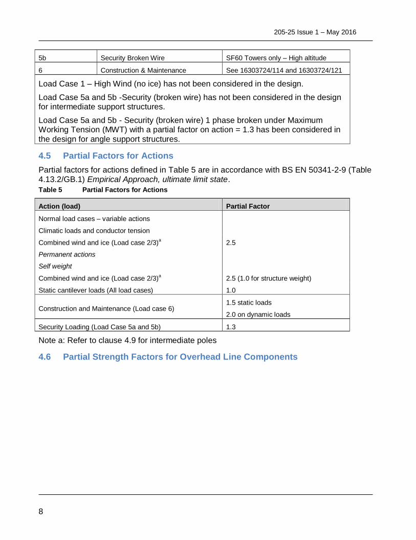
5b Security Broken Wire SF60 Towers only – High altitude
6 Construction & Maintenance See 16303724/114 and 16303724/121
Load Case 1 – High Wind (no ice) has not been considered in the design.
Load Case 5a and 5b -Security (broken wire) has not been considered in the design for intermediate support structures.
Load Case 5a and 5b - Security (broken wire) 1 phase broken under Maximum Working Tension (MWT) with a partial factor on action = 1.3 has been considered in the design for angle support structures.
Partial Factors for Actions 4.5
Partial factors for actions defined in Table 5 are in accordance with BS EN 50341-2-9 (Table 4.13.2/GB.1) Empirical Approach, ultimate limit state.
Table 5 Partial Factors for Actions
Action (load) Partial Factor
Normal load cases – variable actions
Climatic loads and conductor tension
Combined wind and ice (Load case 2/3)a 2.5
Permanent actions
Self weight
Combined wind and ice (Load case 2/3)a
2.5 (1.0 for structure weight)
Static cantilever loads (All load cases) 1.0
Construction and Maintenance (Load case 6) 1.5 static loads
2.0 on dynamic loads
Security Loading (Load Case 5a and 5b) 1.3
Note a: Refer to clause 4.9 for intermediate poles
Partial Strength Factors for Overhead Line Components 4.6
UNCONTROLLED W
HEN PRIN
TED

205-25 Issue 1 – May 2016
9
Table 6 defines the partial strength factors, ɣm, for various overhead line components, as defined in BS 5950-1.
UNCONTROLLED W
HEN PRIN
TED

205-25 Issue 1 – May 2016
10
Table 6 Partial Strength Factors
Component Material Property Partial Strength Factor, ɣm
Steel - Intermediate Support Structure
Resistance of cross sections and of buckling of sections
1.0
Steel Lattice Towers Resistance of cross sections and of buckling of sections
1.0
Timber Poles Resistance of body of pole, cross-section, Elements
1.0
Tension and Suspension Insulator Sets
All string components (based on nominal failing load Mechanical Failing Load (MFL))
1.0
Foundations Concrete (lattice towers) 1.0
Intermediate Foundation (Baulk)
Wood Baulks/direct embedment 1.0
Conductor Parameters 4.7
Table 7 defines the conductor parameters assumed in this design. The named suppliers provided the data to support this study. Other suppliers providing a similar product could be utilised for this design.
Table 7 Conductor Parameters
Phase Wire
Conductor Zebra 400 mm² ACSR
Supplier Details Lumpi Berndorf
Conductor Diameter 28.62 mm
Weight of Conductor 1657 kg/km
Rated Tensile Strength (RTS) 131.9 kN
Ohmic Resistance 0.06740 Ω/km
Earthwire Parameters 4.8
Table 8 defines the conductor parameters assumed in this design. The named suppliers provided the data to support this study. Other suppliers providing a similar product could be utilised for this design.
Table 8 Earthwire Parameters
Earthwire No. 1
Conductor Horse 70 mm² ACSR
Supplier Details (BS 215-2 Table 4)
Conductor Diameter 13.95 mm
Weight of Conductor 538 kg/km
UNCONTROLLED W
HEN PRIN
TED
205-25 Issue 1 – May 2016
11
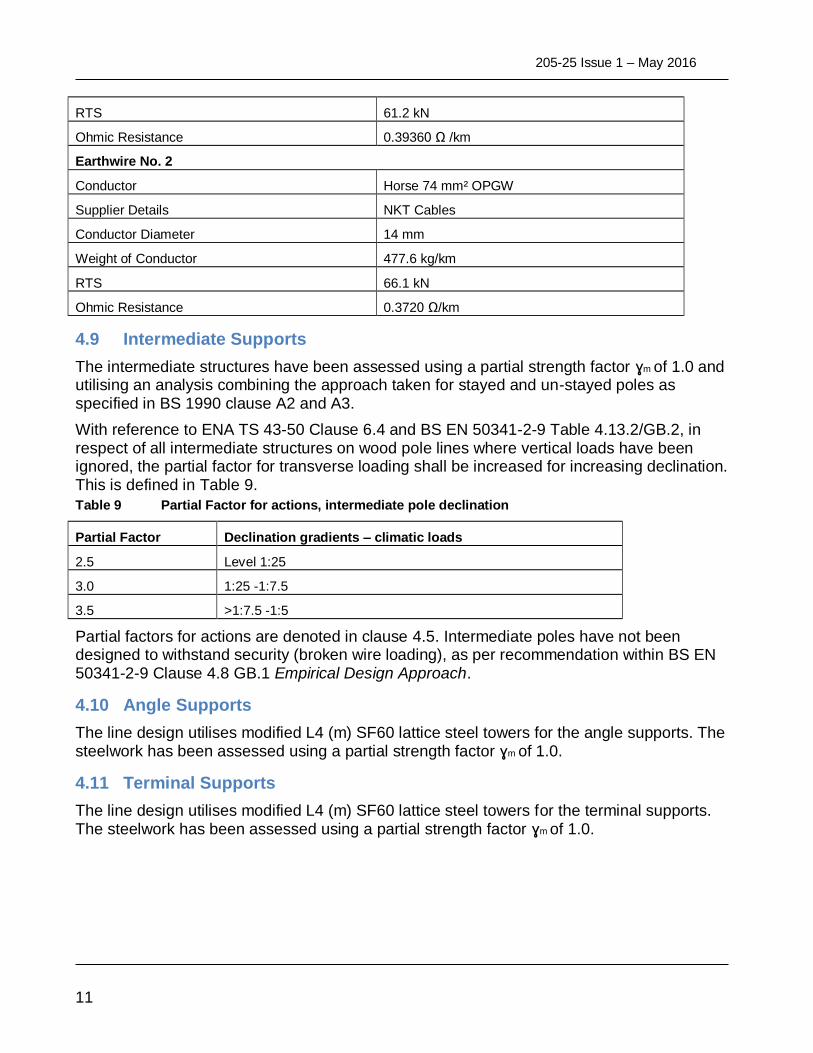
RTS 61.2 kN
Ohmic Resistance 0.39360 Ω /km
Earthwire No. 2
Conductor Horse 74 mm² OPGW
Supplier Details NKT Cables
Conductor Diameter 14 mm
Weight of Conductor 477.6 kg/km
RTS 66.1 kN
Ohmic Resistance 0.3720 Ω/km
Intermediate Supports 4.9
The intermediate structures have been assessed using a partial strength factor ɣm of 1.0 and utilising an analysis combining the approach taken for stayed and un-stayed poles as specified in BS 1990 clause A2 and A3.
With reference to ENA TS 43-50 Clause 6.4 and BS EN 50341-2-9 Table 4.13.2/GB.2, in respect of all intermediate structures on wood pole lines where vertical loads have been ignored, the partial factor for transverse loading shall be increased for increasing declination. This is defined in Table 9.
Table 9 Partial Factor for actions, intermediate pole declination
Partial Factor Declination gradients – climatic loads
2.5 Level 1:25
3.0 1:25 -1:7.5
3.5 >1:7.5 -1:5
Partial factors for actions are denoted in clause 4.5. Intermediate poles have not been designed to withstand security (broken wire loading), as per recommendation within BS EN 50341-2-9 Clause 4.8 GB.1 Empirical Design Approach.
Angle Supports 4.10
The line design utilises modified L4 (m) SF60 lattice steel towers for the angle supports. The steelwork has been assessed using a partial strength factor ɣm of 1.0.
Terminal Supports 4.11
The line design utilises modified L4 (m) SF60 lattice steel towers for the terminal supports. The steelwork has been assessed using a partial strength factor ɣm of 1.0.
UNCONTROLLED W
HEN PRIN
TED

205-25 Issue 1 – May 2016
12
5 Materials
The materials used in the design of this route are in accordance with the relevant British, European, Energy Network Association and NIE Networks standards, as referenced in Section 2.2.
Conductor Sub-system 5.1
The phase conductor system is based on the use of 400 mm² ACSR Zebra conductors. The conductor shall meet the requirements defined in BS 215 – Specification for Aluminium conductors, steel-reinforced for overhead power transmission; Part 2 Aluminium conductors steel-reinforced.
The conductor fittings are designed to be appropriate for use with 400 mm² ACSR Zebra conductors. The fittings selected for this route are based on the requirements defined in BS EN 61284:1998 Overhead lines – Requirements and tests for fittings and BS3288-1:2014 Insulator and conductor fittings for overhead power lines
Insulator Sub-system 5.2
The insulator string design is based on the following specifications:
BS EN 60383
BS EN 61467
BS EN 61109
BS EN 61466-1
BS EN 60071
IEC 60815
206-35 NIE Networks Specification for High Voltage Cap & Pin Insulators.
Earthwire Sub-system 5.3
Two earthwire sub-systems have been considered for this route:
Standard earthwire shall be utilised for line shielding and earth continuity. The standard earthwire sub-system is based on the use of 70 mm² ACSR Horse conductors. The conductor shall meet the requirements defined in BS 215 – Specification for Aluminium conductors, steel-reinforced for overhead power transmission; Part 2 Aluminium conductors steel-reinforced.
The conductor fittings are designed to be appropriate for use with 70 mm² ACSR Horse conductors. The fittings selected for this route are based on the requirements defined in BS EN 61284:1998 Overhead lines – Requirements and tests for fittings and BS 3288-1:2009 Insulator and conductor fittings for overhead power lines.
Communications earthwire shall be used for line shielding, earth continuity and allow for a telecoms connection. The communications earth conductor system is based on the use of 14 mm diameter 74 mm² Horse equivalent OPGW conductors. The conductor shall meet the requirements defined in BS 215 Specification for Aluminium conductors, steel-reinforced for overhead power transmission; and ENA TS 43 -126.
UNCONTROLLED W
HEN PRIN
TED

205-25 Issue 1 – May 2016
13
The earthwire conductor fittings are designed to be appropriate for use with 14 mm diameter 74 mm2
horse equivalent OPGW conductors. The fittings selected for this route are based on the requirements defined in BS EN 61284:1998 Overhead lines – Requirements and tests for fittings and BS 3288-1:2009 Insulator and conductor fittings for overhead power lines.
The route design has considered installation of either two standard earthwires or a single standard earthwire and single communications earthwire per structure.
Tower Steelwork 5.4
All tower/pole steelwork shall be in accordance with BS EN 10025: 2004. Galvanising shall be in accordance with the requirements of BS EN ISO1461. The steelwork has been designed using mild steel equivalent to grade S275JR and high yield steel to grade S355JR sections less than 19 mm.
It is recommended the design engineer considers a check erection of a single angle and terminal tower support structure (including extensions) prior to their use.
Wood Poles 5.5
All wood poles shall comply with the requirements of BS 1990 and NIE Networks specification for wood poles 206-16 issue 10. Poles are assumed to be “for heavy construction” sizes.
NB: As of 30th June 2003 a European Directive came into effect regarding Creosote; the new Directive contains the most up to date information & instructions regarding Creosote. Commission Directive 2001/90/EC were first published on the 26th October 2001. The UK Parliament passed the document 2001/90/EC on the 14th March 2003 and the Directive came into force on the 30th June 2003. The new directive contains the following guidelines, which must be followed when purchasing creosote treated poles. For Northern Ireland Electricity the Creosote used on poles must meet the formulation outlined in 2001/90/EC.
Current Guidelines under 2001/90/EC regarding the formulation of Creosote are;
Creosote used by NIE Networks must contain 0.005% or less by mass of the substance Benzo-a-pyrene.
Creosote used by NIE Networks must contain 3% or less by mass of water extractable phenols.
Support Ancillaries 5.6
Fall arrest attachment locations have been included within the intermediate pole structures. Lattice tower climbing shall be managed in accordance with NIE Networks safety rules. Under Construction Design and Management regulations, Northern Ireland Electricity requirements for a safety attachment system design must be considered, confirmed and quantified prior to construction of the route. Anti climbing devices shall be supplied in accordance with ENA TS 43-90. Other signs, such as colour plates or pole numbers etc., shall be specified by NIE Networks at the construction stage.
UNCONTROLLED W
HEN PRIN
TED

205-25 Issue 1 – May 2016
14
6 Line Design
This document has been produced to provide guidance for the installation of a 200 MVA single circuit overhead line. The details noted within this document are intended to provide a feasible solution to install the proposed conductor system on the range of support structures. It is expected that a competent overhead line design engineer will check and verify the application for site specific conditions prior to construction commencing.
Span Lengths Intermediate 6.1
6.1.1 Support Structures
Pole foundations are designed to suit each location and to be adequate for the loading. It is recommended guidance contained within document 16303724/0116 is used for the selection of appropriate pole type and foundation. Detailed design may be required when poles are heavily utilised. No uplift loads are permissible on the intermediate structures (see clause 6.3).
6.1.2 Angle and Terminal Support Structures
Table 10 details the criteria used for the design of the angle and terminal support structures. Site specific loading conditions and external clearance assessments may mean that the criterion is not fully achieved in practice.
Table 10 Angle & Terminal Support Structure Criteria Guide
Description
Value (m)
‘Normal’ environment
‘Extreme’ environment (300m-500m Above Mean Sea Level(AMSL))
Maximum Single Span – Angle Structures 350 130
Maximum Terminal Span 300 130
Maximum Sum of Adjacent Spans 680 220
Maximum Weight Span 400 320
Minimum Weight Span 0(a)
0
Maximum Single Weight Span 350 280
Maximum Terminal Weight Span 300 240
Maximum Wind Span 340 220
Maximum Single Wind Span 175 110
Maximum Equivalent Span 350 130
Notes:
a) Minimum weight span for standard design shall be 0m. An assessment of the design capacity of the earthwire and cross-arms under negative weight spans including
UNCONTROLLED W
HEN PRIN
TED

205-25 Issue 1 – May 2016
15
structure modifications is documented within 16303724/0117. However, the full strengthening requirements can be found in 16303724/0121.
NB: The adjacent intermediate structures may limit the span onto tower support structures due to its limited wind span capacity. If the design includes angle to angle or angle to terminal structures, an increase in span length may be achieved following in-span clearances checks.
Angle of Deviation 6.2
Table 11 lists the minimum and maximum angle of deviation for each support structure.
Table 11 Angle of Deviation
Support Structure Min Angle of Deviation Max Angle of Deviation
Intermediate Pole 0° 0°
Angle Structure 0-30 0° 30°
Angle Structure 30-60 30° 60°
Terminal Structure 0° 10°(angle of entry)
Minimum Conductor Weight at Intermediate Support Structures 6.3
The conductor weight supported by any suspension insulator set shall not be less than 35 percent (%) of the total weight of the corresponding line conductor in the two adjacent spans. This condition shall apply at minimum temperature (-5.6°C) without wind or ice loading. Additional internal clearance checks / mitigation (set weights) may be required if this condition is not maintained.
Vertical Conductor load 6.4
The vertical conductor load (V) imposed on a cross-arm can be assumed, for practical purposes, to be the sum of the weight of conductor in half the adjacent spans plus the downpull imposed by the gradient on both sides of the support. This may be calculated as follows in accordance with ENA TS 43-50:
V(kg) =
Weight Span (metres) =
• Where L1 and L2 are adjacent span lengths in metres.
• W is weight (augmented mass) of the conductor in kg per metre.
• Tmax is the maximum design tension for the conductor in kgf.
• Tan θ1 and Tan θ2 are the gradients on each side of the support.
Stringing Basis 6.5
The conductor design basis should be a limit of a maximum tension of 20% of the phase conductor conductor breaking load (NBL) under an assumed everyday condition. “Everyday Condition” is specified
UNCONTROLLED W
HEN PRIN
TED

205-25 Issue 1 – May 2016
16
is specified as still air, no ice at 15 °C. The Maximum Working Tension (MWT) to use in the design is design is calculated at -5.6 °C with radial icing of 9.5 mm and an applied wind load of 380 N/m². The N/m². The earthwire design basis has been developed to support the overall system design and is and is therefore reduced below 20% of breaking load at everyday conditions. The conductor design design basis assumptions are defined in Table 12,
Table 13 and Table 14.
Table 12 Conductor Rated Strength
Conductor Type Rated Strength (RS) Factor of Safety(FOS) (%) of RS under MWT
Zebra 400 mm² ACSR 131.90 kN 2.60 (38%)
Horse 70 mm² ACSR 61.20 kN 2.50 (40%)
Horse 74 mm² OPGW (NKT) 66.10 kN 2.70 (37%)
Table 13 Stringing Basis
Type
Every Day Tension (EDT)(a,d)
(No Wind No Ice) Over Tension Temperature
(c)
Max Tension Temp.
Zebra ACSR
26.4 kN +15°C 30
Horse ACSR
12.2 kN +15°C 15
Horse OPGW
12.2 kN +15°C 15
Table 14 Maximum Working Tension used in Design
Type
MWT
(Normal Altitude)
MWT
(High Altitude)
Max Tension Temp. Max Tension Temp.
Zebra ACSR
48.8kN -5.6°C 50.6kN -5.6°C
Horse OPGW
(e)
27.9kN -5.6°C 24.8kN -5.6°C
Notes:
a) A limit of a maximum conductor tension = RS/5 to reduce wind-induced Aeolian vibration. Earthwire tensions to be balanced at EDT.
b) Conductor MWT derived from EDT sag basis. c) An allowance for creep of the conductor in service should be included by over-tension of the
conductor during erection. This is expressed as an assumed temperature shift in accordance with ENA TS 43-100 Table 2
d) Earthwire shall not sag below phase conductor at assumed everyday day temperature.
UNCONTROLLED W
HEN PRIN
TED

205-25 Issue 1 – May 2016
17
e) Higher MWT value used for design on both earthwire peaks.
Use of back stays 6.6
The stringing basis given in this document has been chosen in order to obtain the best use of the completed route. In order to utilise the everyday tension as the principle design basis, it will be necessary to erect at higher tensions than would normally be considered safe on the SF60 structures. The impact of the high erection tensions must be mitigated by the use of temporary back stays during the initial construction stage. (See document 16303724/0121 for more details).
Internal Clearances 6.7
Table 15 indicates 132 kV clearances in accordance with original L4 (m) specification ENA TS 43-7 Issue 2 (unless specified) utilised within the design to provide an onerous internal clearance envelope (system voltage 110 kV).
Table 15 Internal Clearances
Internal Clearances
Phase to Phase 1.4 m (ENA TS 43-125)
Phase to Phase Down-leads (still air) 2.5 m
Phase to Phase Down-leads (max sag opposing conductor swing)
1.5 m
Live metal to support steelwork/earthed fittings/wood pole (suspension insulators)
Suspension insulator sets inclined between 0° and 10° from the vertical and jumper loops hanging vertically
1.2 m
Suspension insulator sets inclined between 10° and 35° from the vertical
0.9 m
Live metal to support steelwork/earthed fittings/wood pole (tension insulators)
Jumper loops hanging vertically 1.2 m
Jumpers loops inclined 20° from vertical 0.9 m
The minimum clearances must be maintained and where conductors are free to move, such movement must be taken into account.
Line conductor shielding angle by earth conductor (from vertical in still air)
45°
Max swing of earthwire conductor fittings from vertical (Intermediate pole)
45°
External Clearances 6.8
Route profiles should be created to check external clearances. The stringing basis for this system is given in clause 6.5.
UNCONTROLLED W
HEN PRIN
TED

205-25 Issue 1 – May 2016
18
The minimum height of line conductors above ground and features shall conform to Electricity Energy Networks ENA TS 43-8 Issue 4, unless otherwise specified.
Downleads 6.9
For the purpose of terminal tower design the down-lead loadings have been assumed to be zero. All down-lead sets have been designed for low-duty operation.
Geotechnical Parameters 6.10
Standard design parameters have been included in reports 16303724/0116 and 16303724/0118 to allow foundation design assessments to be undertaken where ground conditions are considered standard. A desktop study and suitable ground investigation should be commissioned along the route to identify sites where standard foundations may be employed and to quantify design parameters to allow the design of special non-standard foundations to be carried out.
Foundations 6.11
6.11.1 Intermediate support foundations
For intermediate supports, based on generic ground conditions contained in ENATS 43-125, some baulk designs have been prepared. For some soil conditions and loadings (particularly weak peat), baulk foundations are unsuitable and it is recommended to use the design of special concrete pad foundations based on the soil parameters ascertained by a suitably qualified geotechnical engineer. Foundation design follows the prescriptive approach detailed in ENATS 43-125. Please refer to document 16303724/0118 for further details.
6.11.2 Foundation Installation at Intermediate Supports
For this type of foundation it is critical that the backfill operations are closely monitored. The minimum depth to the top baulk is 0.75 m below ground level to reduce the chances of damage by agricultural plant undertaking ploughing operations. Backfill must be of suitable quality material, grading and compaction to achieve a density equivalent to the surrounding soil.
Construction method statements and installation design studies shall be completed at detailed design stage by the construction contractor; high level installation methodology is noted below;
The poles are installed by excavating a short trench in the ground, standing the pole in the trench, and backfilling the excavated soil by compaction of the soil in layers. The width of the trench provides space for the pole position to be aligned with other poles in the line.
The pole foundation must be backfilled on completion of the pole placement, confirmation of pole verticality and checks that the cross-arm is set square to the line alignment. The soil around the foundation is compacted with a hydraulic powered tamper. Typically the soil is backfilled slowly and each 150 mm layer (max. may be reduced depending on contractor methodology) thoroughly compacted. The site engineer may replace the existing material subject to investigation of the existing soil with a quality back fill material or fill enhancer as specified by the detailed designer. The backfills must be compacted to achieve the same
UNCONTROLLED W
HEN PRIN
TED

205-25 Issue 1 – May 2016
19
density, compaction and properties as the parent soil; alternatively, lean mix concrete may be used in place of compacted soil.
A visual examination of the structure founding location should be made after 2 months (or as specified by detail designer) to ensure the backfill has not settled below the existing ground level. Any settlement will require additional backfill and compaction.
6.11.3 Angle and Terminal Tower Foundations
Completed foundation designs have been provided for pad and column foundations for SF60 (0-30), SF60(30-60) and SF60(Terminal +Sealing End Platform(SEP)). Foundations have been designed to withstand worst case environmental loading as described in this report. Foundations have been produced for soil class 1 and 2 only. These soil grades relate to ENATS 43-125 soil designations; Class 2 for sites where SPT-N values of over 20 or cu values of over 50 kPa and ground water level is well below the base of the footing; class 2 for sites where SPT-N values of 10 to 20 or cu values of 35 to 50 kPa and ground water level is well below the base of the footing. See report 163037240/118 for further details. Towers outside these parameters should be designed as specials based on the analysis of the ground investigation report by a suitably qualified geotechnical engineer.
Earthing 6.12
All structures shall be earthed. The foundations should achieve a footing resistance of 100 or less (ENATS 43-125) unless a lower limit is specified. However touch and step potentials (ROEP) at the base must be considered in the detailed design phase.
If there is concern over achieving stated resistance, earthing studies must be undertaken during the detailed design phase to assess the impact and suitable solution. Possible mitigation measures may take the form of copper stranded cable/tape or steel/aluminium clad steel stranded wire or earth rods situated within the backfill at the base of the structure in order to reduce the footing resistance.
Operations and Maintenance 6.13
The operations and maintenance manual 16303724/0114 provides information on construction design features of the 200 MVA system which will allow a competent contractor to develop safe methods of work. These demonstrate that key operations are achievable and have been considered at a design stage.
UNCONTROLLED W
HEN PRIN
TED