Embed Size (px)
Citation preview

Operator’s Manual
Ingersoll Rand’s Climate Solutions sector delivers energy-effi cient HVACR solutions for customers globally. Its world class brands include Thermo King, the leader in transport temperature control and Trane, a provider of energy effi cient heating, ventilating and air conditioning systems, building and contracting services, parts support and advanced controls for commercial buildings and homes.
©2013 Ingersoll-Rand Company Printed in U.S.A.
Precedent™C-600
TK 55692-2-OP (Rev. 2, 12/15)

Copyright© 2013 Thermo King Corp., Minneapolis, MN, USAPrinted in USA
PrecedentTM
C-600TK 55692-2-OP (Rev. 2, 12/15)
DisclaimerThis manual is published for informational purposes only. Thermo King Corporation makes norepresentations or warranties, express or implied, with respect to the information, recommendationsand descriptions contained in this manual and such information, recommendations and descriptionsshould not be regarded as all-inclusive or covering all contingencies. In the event you have anyquestions or require further information, please contact your local Thermo King dealer.
The procedures described herein should only be undertaken by suitably qualified personnel. Failure toimplement these procedures correctly may cause damage to the Thermo King unit or other property orpersonal injury.
Thermo King Corporation and its affiliates shall have no liability in contract or tort (including negligenceand/or strict liability) or otherwise, to any person or entity for any personal injury, property damage orany other direct, indirect, special or consequential damage or liability whatsoever, arising out of orresulting from any actions by any person that are contrary to this manual or any of the information,recommendations or descriptions contained herein or the failure of any person to implement theprocedures described herein correctly or to follow caution and safety decals located on the ThermoKing unit.

3
Table Of ContentsIntroduction . . . . . . . . . . . . . . . . . . . . . . . . . . . . . . . . . 7
EPA Emission Control System Warranty Statement 8
Safety Precautions . . . . . . . . . . . . . . . . . . . . . . . . . . 11General Safety Practices . . . . . . . . . . . . . . . . . . . . . . 11Automatic Start/Stop Operation . . . . . . . . . . . . . . . . . 12Electrical Hazard . . . . . . . . . . . . . . . . . . . . . . . . . . . . . 12Battery Installation and Cable Routing . . . . . . . . . . . . 12Refrigerant . . . . . . . . . . . . . . . . . . . . . . . . . . . . . . . . . 13Refrigerant Oil . . . . . . . . . . . . . . . . . . . . . . . . . . . . . . . 14First Aid . . . . . . . . . . . . . . . . . . . . . . . . . . . . . . . . . . . . 14
First Aid–Refrigerant . . . . . . . . . . . . . . . . . . . . . . . 14First Aid–Refrigerant Oil . . . . . . . . . . . . . . . . . . . . 14
Safety Decals and Locations . . . . . . . . . . . . . . . . . . . 15Condenser and Evaporator Fans . . . . . . . . . . . . . 15High Voltage Components . . . . . . . . . . . . . . . . . . 15Do Not Use Ether Starting Aids . . . . . . . . . . . . . . 17
Unit Description . . . . . . . . . . . . . . . . . . . . . . . . . . . . .18Unit Overview . . . . . . . . . . . . . . . . . . . . . . . . . . . . . . . .18Features and Options . . . . . . . . . . . . . . . . . . . . . . . . .19Diesel Engine . . . . . . . . . . . . . . . . . . . . . . . . . . . . . . . .20ELC (Extended Life Coolant) . . . . . . . . . . . . . . . . . . . .21EMI 3000 . . . . . . . . . . . . . . . . . . . . . . . . . . . . . . . . . . .22Thermo King X430L Reciprocating Compressor . . . . .22Electronic Throttling Valve . . . . . . . . . . . . . . . . . . . . . .22SMART REEFER 4 (SR-4) Control System . . . . . . . . .23
Diesel Operation . . . . . . . . . . . . . . . . . . . . . . . . . .23Electric Operation . . . . . . . . . . . . . . . . . . . . . . . . .24
CYCLE-SENTRY Start-Stop Controls . . . . . . . . . . . . .24Data Logging . . . . . . . . . . . . . . . . . . . . . . . . . . . . .25
OptiSet Plus . . . . . . . . . . . . . . . . . . . . . . . . . . . . . . . . .26FreshSet . . . . . . . . . . . . . . . . . . . . . . . . . . . . . . . . . . .26
Defrost . . . . . . . . . . . . . . . . . . . . . . . . . . . . . . . . . .26Opening the Front Doors . . . . . . . . . . . . . . . . . . . . . . .27Engine Compartment . . . . . . . . . . . . . . . . . . . . . . . . . .28Unit Protection Devices . . . . . . . . . . . . . . . . . . . . . . . .28

4
Remote Status Display (Optional) . . . . . . . . . . . . . . 32
Manual Pretrip Inspection(Before Starting the Unit) . . . . . . . . . . . . . . . . . . . . . 35
Operating Instructions . . . . . . . . . . . . . . . . . . . . . . . 37SMART REEFER 4 (SR-4) Controller Overview . . . . . 37Control Panel . . . . . . . . . . . . . . . . . . . . . . . . . . . . . . . . 38
Control Panel Display . . . . . . . . . . . . . . . . . . . . . . 38Display Icons . . . . . . . . . . . . . . . . . . . . . . . . . . . . . 39Hard Keys . . . . . . . . . . . . . . . . . . . . . . . . . . . . . . . 40Soft Keys . . . . . . . . . . . . . . . . . . . . . . . . . . . . . . . . 40
Turning Unit On . . . . . . . . . . . . . . . . . . . . . . . . . . . . . . 41If a Flash Drive is Connected: . . . . . . . . . . . . . . . . 41Configurable Soft Keys . . . . . . . . . . . . . . . . . . . . . 43Display Heater . . . . . . . . . . . . . . . . . . . . . . . . . . . 44If a Language is Enabled . . . . . . . . . . . . . . . . . . . 44If Log Alarms are Present . . . . . . . . . . . . . . . . . . . 45
Turning The Unit Off . . . . . . . . . . . . . . . . . . . . . . . . . . 47The Standard Display . . . . . . . . . . . . . . . . . . . . . . . . . 47The TemperatureWatch Display . . . . . . . . . . . . . . . . . 48Changing The Setpoint . . . . . . . . . . . . . . . . . . . . . . . . 49
Numerical Setpoints . . . . . . . . . . . . . . . . . . . . . . . 49Named Products - OptiSet Plus . . . . . . . . . . . . . . 50
Both Numerical Setpoints and Named Products . 50Changing the Setpoint - Numerical Setpoint . . . . 51Changing the Setpoint - Named Product . . . . . . . 55Changing the Setpoint - Both Numerical Setpoint and Named Product Available . . . . . . . . . . . . . . . 59
Starting the Diesel Engine . . . . . . . . . . . . . . . . . . . . . 60Starting the Electric Motor . . . . . . . . . . . . . . . . . . . . . 61Switching from Diesel to Electric . . . . . . . . . . . . . . . . 62Switching from Electric to Diesel . . . . . . . . . . . . . . . . 63Initiating a Manual Defrost Cycle . . . . . . . . . . . . . . . . 64Terminating a Defrost Cycle . . . . . . . . . . . . . . . . . . . . 67Selecting Cycle Sentry or Continuous Mode . . . . . . . 67Using the Gauges Key . . . . . . . . . . . . . . . . . . . . . . . . 71
Gauges Available . . . . . . . . . . . . . . . . . . . . . . . . . 71Using The Sensors Key . . . . . . . . . . . . . . . . . . . . . . . 73
Sensors Available . . . . . . . . . . . . . . . . . . . . . . . . 74Using the Main Menu . . . . . . . . . . . . . . . . . . . . . . . . . 75
Pretrip . . . . . . . . . . . . . . . . . . . . . . . . . . . . . . . . . 76Performing a Pretrip Test . . . . . . . . . . . . . . . . . . . 78Flash Drive . . . . . . . . . . . . . . . . . . . . . . . . . . . . . . 83Flash Drive Icon . . . . . . . . . . . . . . . . . . . . . . . . . . 83
Selecting the Flash Drive Menu from the Main Menu (If Already Connected) . . . . . . . . . . . . . . . . . . . . . . . . 84Removing the Flash Drive . . . . . . . . . . . . . . . . . . . . . 85

5
Languages (If Enabled) . . . . . . . . . . . . . . . . . . . . . . . . 86Available Languages . . . . . . . . . . . . . . . . . . . . . . 86
Alarms . . . . . . . . . . . . . . . . . . . . . . . . . . . . . . . . . . . . . 90Log Alarms . . . . . . . . . . . . . . . . . . . . . . . . . . . . . . 90Check Alarms . . . . . . . . . . . . . . . . . . . . . . . . . . . . 91Shutdown Alarms . . . . . . . . . . . . . . . . . . . . . . . . . 91Pretrip Alarms . . . . . . . . . . . . . . . . . . . . . . . . . . . . 92Clearing Alarm Codes . . . . . . . . . . . . . . . . . . . . . 92Displaying and Clearing Alarm Codes . . . . . . . . . 93
Gauges . . . . . . . . . . . . . . . . . . . . . . . . . . . . . . . . . . . . 98Displaying Gauges . . . . . . . . . . . . . . . . . . . . . . . . 98
Sensors . . . . . . . . . . . . . . . . . . . . . . . . . . . . . . . . . . . . 99Displaying Sensors . . . . . . . . . . . . . . . . . . . . . . . . 99
Data Logger (CargoWatch) . . . . . . . . . . . . . . . . . . . . 100Sending Start of Trip Marker to CargoWatch and Service-Watch Data Loggers . . . . . . . . . . . . . . . . . . . . . . . . . 101Hourmeters . . . . . . . . . . . . . . . . . . . . . . . . . . . . . . . . 104
Viewing Hourmeters . . . . . . . . . . . . . . . . . . . . . . 104Mode Menu . . . . . . . . . . . . . . . . . . . . . . . . . . . . . . . . 106
SmartPower Electric Standby Option . . . . . . . . . 113Time . . . . . . . . . . . . . . . . . . . . . . . . . . . . . . . . . . 117Clear All ECU Faults . . . . . . . . . . . . . . . . . . . . . . 118
Optional Rear Remote Control Panel . . . . . . . . . . .121Rear Remote Control Panel Functionality . . . . . . . . .121
Rear Remote Control Action Set to Run . . . . . . .121Rear Remote Control Action Set to STAND BY .122Keypad . . . . . . . . . . . . . . . . . . . . . . . . . . . . . . . . .124Display . . . . . . . . . . . . . . . . . . . . . . . . . . . . . . . . .125Reading a Typical Remote Standard Display . . .126Remote Control Panel Lockout . . . . . . . . . . . . . .126
Turning the Unit ON or OFF (Configured for STANDBY Operation) . . . . . . . . . . . . . . . . . . . . . . . . . . . . . .127Turning the Unit On and Off (Configured for RUN Operation) . . . . . . . . . . . . . . . . . . . . . . . . . . . . . . . . .127Changing the Setpoint . . . . . . . . . . . . . . . . . . . . . . . .128Selecting Cycle-Sentry or Continuous Mode . . . . . . .129Displaying the Discharge Air Temperature . . . . . . . .130Viewing and Clearing Alarm Codes . . . . . . . . . . . . . .131Starting a Manual Defrost Cycle . . . . . . . . . . . . . . . .132Sending a Start of Trip Marker . . . . . . . . . . . . . . . . . .133Running a Pretrip Test . . . . . . . . . . . . . . . . . . . . . . . .134
Loading and Enroute Inspections . . . . . . . . . . . . .136Pre-Loading Inspection . . . . . . . . . . . . . . . . . . . . . . .136Post-Loading Inspection . . . . . . . . . . . . . . . . . . . . . .138Enroute Inspections . . . . . . . . . . . . . . . . . . . . . . . . . .139

6
Alarm Codes . . . . . . . . . . . . . . . . . . . . . . . . . . . . . . 142Introduction . . . . . . . . . . . . . . . . . . . . . . . . . . . . . . . . 142Alarm Types . . . . . . . . . . . . . . . . . . . . . . . . . . . . . . . 142Clearing Alarm Codes . . . . . . . . . . . . . . . . . . . . . . . . 145
Jump Starting . . . . . . . . . . . . . . . . . . . . . . . . . . . . . 171
Specifications . . . . . . . . . . . . . . . . . . . . . . . . . . . . . 175Engine . . . . . . . . . . . . . . . . . . . . . . . . . . . . . . . . . . . . 175Belt Tension . . . . . . . . . . . . . . . . . . . . . . . . . . . . . . . . 178Refrigeration System . . . . . . . . . . . . . . . . . . . . . . . . . 179Electrical Control System . . . . . . . . . . . . . . . . . . . . . 181Electrical Components . . . . . . . . . . . . . . . . . . . . . . . . 182Electric Heater Strips . . . . . . . . . . . . . . . . . . . . . . . . . 184Electrical Standby (Smart Power Units Only) . . . . . . 184
Electric Motor and Overload Relay . . . . . . . . . . . 184Standby Power Cord Requirements . . . . . . . . . . 185
Electric Fuel Heater (Optional) . . . . . . . . . . . . . . . . . 185
Warranty . . . . . . . . . . . . . . . . . . . . . . . . . . . . . . . . . 186
Glossary . . . . . . . . . . . . . . . . . . . . . . . . . . . . . . . . . 187
Maintenance Inspection Schedule . . . . . . . . . . . . 193
Serial Number Locations . . . . . . . . . . . . . . . . . . . . 198
Emergency Cold Line . . . . . . . . . . . . . . . . . . . . . . . 201
Recover Refrigerant . . . . . . . . . . . . . . . . . . . . . . . . 202
CALIFORNIAProposition 65 Warning . . . . . . . . . . . . . . . . . . . . . 203
Index . . . . . . . . . . . . . . . . . . . . . . . . . . . . . . . . . . . . . 204

7
IntroductionThere is nothing complicated about operating and maintaining your Thermo King unit, but a few minutes studying this manual will be time well spent.
Performing pre-trip checks and enroute inspections on a regular basis will minimize on-the-road operating problems. A regular maintenance program will also help to keep your unit in top operating condition. If factory recommended procedures are followed, you will find that you have purchased the most efficient and dependable temperature control system available.
All service requirements, major and minor, should be handled by a Thermo King dealer for four very important reasons:
• They are equipped with the factory recommended tools to perform all service functions
• They have factory trained and certified technicians
• They have genuine Thermo King replacement parts
• The warranty on your new unit is valid only when the repair and replacement of component parts is performed by an authorized Thermo King dealer.
IMPORTANT: This manual is published for informational purposes only and the information furnished herein should not be considered as all-inclusive or meant to cover all contingencies. If more information is required, consult your Thermo King Service Directory for the location and telephone number of the local dealer.

8
EPA Emission Control System Warranty StatementThermo King warrants to the initial owner and each subsequent owner that the certified, non-road diesel engine in your unit is:
1. Designed, built and equipped so as to conform, at the time of sale, with all applicable regulations adopted by the United States Environmental Protection Agency (EPA).
2. Free from defects in materials and workmanship in specific emission related parts for a period of five years or 3,000 hours of operation, whichever comes first, after date of delivery to the initial owner.
If an emission-related part or component fails during the warranty period, it will be repaired or replaced. Any such part or component repaired or replaced under warranty is warranted for the warranty period.
During the term of this warranty, Thermo King will provide, through a Thermo King authorized service dealer or other establishment authorized by Thermo King, repair or replacement of any warranted part at no charge to the non-road engine owner.
In emergency, repairs may be performed at any service establishment, or by the owner, using any replacement part. Thermo King will reimburse the owner for their expenses, including diagnostic charges for such emergency repair. These expenses shall not exceed Thermo King’s suggested retail price for all warranted parts replaced, and labor changes based on Thermo King’s recommended time allowance for the warranty repair and the geographically appropriate hourly labor rate.

EPA Emission Control System Warranty Statement
9
Any replacement part can be used for maintenance or repairs. The owner should ensure that such parts are equivalent in design and durability to genuine Thermo King parts. However, Thermo King is not liable for parts that are not genuine Thermo King parts.
A part not being available within 30 days or repair not being completed within 30 days constitutes an emergency.
As a condition of reimbursement, replaced parts and received invoices must be presented at a place of business of a Thermo King authorized service dealer or other establishment authorized by Thermo King.
This warranty covers the following emission-related parts and components:
• Fuel Injection System
• Intake Manifold
• Exhaust Manifold
• Miscellaneous hoses, clamps, connectors and sealing devices used in the above systems.
If failure of one of these parts or components results in failure of another part or component, both will be covered by this warranty.
ResponsibilitiesThis warranty is subject to the following:
Thermo King Corporation ResponsibilitiesDuring the emission warranty period, if a defect in material or workmanship of a warranted part or component is found, Thermo King will provide:
• New, remanufactured, or repaired parts or components required to correct the defect.
NOTE: Items replaced under this warranty become the property of Thermo King.
• Labor, during normal working hours, required to make the warranty repair. This includes diagnosis and labor to remove and install the engine, if necessary.

EPA Emission Control System Warranty Statement
10
Owner ResponsibilitiesDuring the emission warranty period, the owner is responsible for:
• The performance of all required maintenance. A warranty claim will not be denied because the scheduled maintenance was not performed. However, if the lack of required maintenance was the reason for the repair, then the claim will be denied.
• Premium of overtime cost.
• Cost to investigate complaints that are not caused by defects in Thermo King material or workmanship.
• Providing timely notice of a warrantable failure and promptly making the product available for repair.
LimitationsThermo King is not responsible for resultant damages to an emission-related part or component resulting from:
• Any application or installation Thermo King deems improper as explained in this Operator’s Manual, or any other manuals provided for the unit.
• Attachments, accessory items, or parts not authorized for use by Thermo King.
• Improper off-road engine maintenance, repair or abuse.
• Owner’s unreasonable delay in making the product available after being notified of a potential product problem.
This warranty is in addition to Thermo King’s standard warranty applicable to the off-road engine product involved.
Remedies under this warranty are limited to the provision of material and services as specified herein. Thermo King is not responsible for incidental or consequential damages such as downtime or loss of engine powered equipment.
11
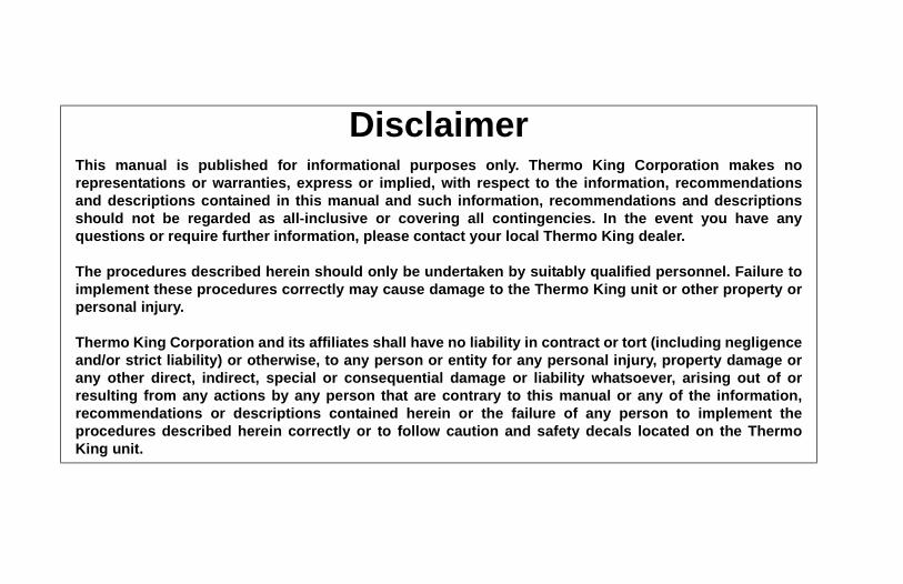
Safety PrecautionsThermo King recommends that servicing be done only by a Thermo King dealer. However, you should be aware of several safety practices. This chapter gives basic safety precautions for working with Thermo King units and describes the safety stickers on your unit that you should be familiar with.
General Safety PracticesDANGER: NEVER operate the unit with the compressor discharge valve closed. Doing so could cause the compressor to explode, causing death or serious injury.
WARNING: Always wear goggles or safety glasses when working with or around the refrigeration system or battery. Refrigerant or battery acid can cause permanent damage if it comes in contact with your eyes.
WARNING: Keep hands and loose clothing clear of fans and belts at all times when the unit is operating or when opening or closing compressor service valves.
WARNING: Exposed coil fins can cause painful lacerations. Service work on the evaporator or condenser coils should be done by a certified Thermo King technician.
WARNING: Do not apply heat to a closed cooling system. Before applying heat to a cooling system, drain it. Then flush it with water and drain the water. Antifreeze contains water and ethylene glycol. The ethylene glycol is flammable and can ignite if the antifreeze is heated enough to boil off the water.
CAUTION: Use extreme caution when drilling holes in the unit. Drilling into electrical wiring or refrigerant lines could cause a fire. Do not drill into structural components.

Safety Precautions
12
Automatic Start/Stop OperationThis unit is capable of automatic operation and could start at any time without warning.
Electrical Hazard
Battery Installation and Cable Routing
WARNING: The unit can start at any time without warning. Press the OFF key on the control panel and place the microprocessor On/Off switch in the Off position before inspecting or servicing any part of the unit.
DANGER: Dangerous three phase AC electric power is present whenever the unit is operating in either Diesel Mode or Electric Mode and whenever the unit is connected to a source of external standby power. Voltages of this magnitude can be lethal. Exercise extreme caution when working on the unit.
WARNING: Improperly installed battery could result in a fire or explosion. A Thermo King approved battery must be installed and properly secured to the battery tray.
WARNING: Improperly installed battery cables could result in fire or explosion. Battery cables must be installed, routed and secured properly to prevent them from rubbing, chaffing or making contact with hot, sharp or rotating components.
WARNING: Do not attach fuel lines or any additional wiring harnesses to the battery cables as this could cause an electrical fire.
CAUTION: Do not connect other manufacturer’s equipment or accessories to the Thermo King unit. This could result in severe damage to equipment and void the warranty.

Safety Precautions
13
RefrigerantAlthough fluorocarbon refrigerants are classified as safe, use caution when working with refrigerants or in areas where they are being used.
CAUTION: Set all unit electrical controls to the OFF position before connecting battery cables to the battery to prevent unit from starting unexpectedly and causing personal injury.
CAUTION: Always wear protective clothing, gloves and eye wear when handling and installing batteries. Battery acid can cause serious burns when exposed to eyes or skin. If battery acid contacts skin or clothing, wash immediately with soap and water. If acid enters your eye, immediately flood it with running cold water for at least twenty minutes and get medical attention immediately.
CAUTION: Always cover battery terminals to prevent them from making contact with metal components during battery installation. Battery terminals grounding against metal could cause the battery to explode.
DANGER: Fluorocarbon refrigerants can produce toxic gases. In the presence of an open flame or electrical short, these gases are severe respiratory irritants CAPABLE OF CAUSING DEATH.
DANGER: Fluorocarbon refrigerants tend to displace air and can cause oxygen depletion which could result in DEATH BY SUFFOCATION. Provide adequate ventilation in enclosed or confined areas.
WARNING: Fluorocarbon refrigerants evaporate rapidly, freezing anything they contact if accidentally released into the atmosphere from the liquid state.
Safety Precautions
14
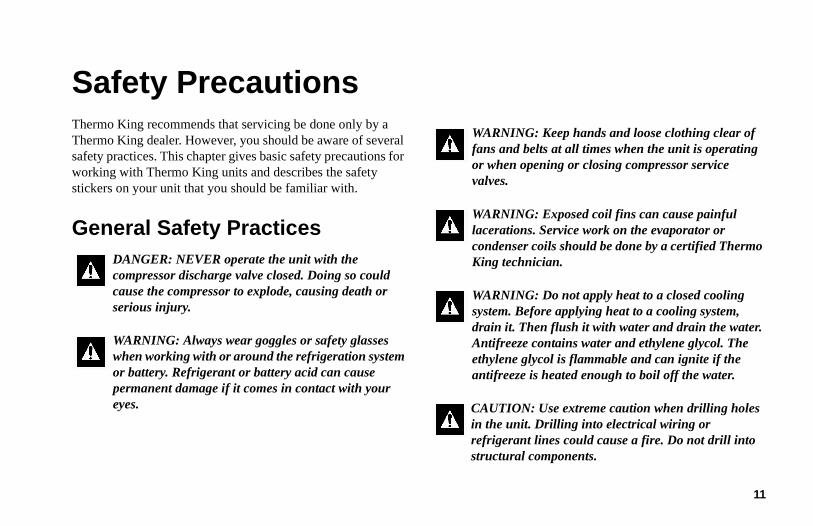
Refrigerant OilObserve the following precautions when working with or around refrigerant oil:
First Aid
First Aid–RefrigerantEyes: For contact with liquid, immediately flush eyes with large amounts of water. Get prompt medical attention.
Skin: Flush areas with large amounts of warm water. Do not apply heat. Wrap burns with dry, sterile, bulky dressing to protect from infection or injury. Get prompt medical attention.
Inhalation: Move victim to fresh air and restore breathing if necessary. Stay with victim until emergency personnel arrive.
First Aid–Refrigerant OilEyes: Immediately flush eyes with large amounts of water for at least 15 minutes while holding the eyelids open. Get prompt medical attention.
Skin: Remove contaminated clothing. Wash thoroughly with soap and water. Get medical attention if irritation persists.
Inhalation: Move victim to fresh air and restore breathing if necessary. Stay with victim until emergency personnel arrive.
Ingestion: Do not induce vomiting. Immediately contact local poison control center or physician.
WARNING: Always wear goggles or safety glasses to protect eyes from refrigerant oil contact.
WARNING: Protect skin and clothing from prolonged or repeated contact with refrigerant oil. Rubber gloves are recommended.
WARNING: Wash thoroughly immediately after handling refrigerant oil to prevent irritation.

Safety Precautions
15
Safety Decals and Locations
Condenser and Evaporator FansBe aware of the warning nameplates near the condenser fans and evaporator fans (example in Figure 1).
Figure 1: Fan Warning
High Voltage ComponentsVarious components on the Precedent unit operate using 220/3/60 or 460/3/60 high voltage and are identified by warning nameplates (examples in Figure 2). All high voltage wiring is identified by ORANGE conduiting. Be aware of the locations of these components. Only certified, trained technicians can service them.
Figure 2: High Voltage Warning
NOTE: See Figure 3 and Figure 4 for high voltage component locations.
AMA1581AMA1580AMA1579

Safety Precautions
16
1. Condenser Motors 4. High Voltage Control Box2. Evaporator Motor 5. AC Generator3. High Voltage
Distribution Box6. Electric Standby Motor &
Power Receptacle (SmartPower Option)
Figure 3: High Voltage Component Locations (Front)
1
2
3
4
5
6
7. Evaporator Motor 9. High Voltage Junction Box
8. High Voltage Heater Strips
All ORANGE conduiting contains High Voltage
Figure 4: High Voltage Component Locations (Rear)
7
8
99

Safety Precautions
17
Do Not Use Ether Starting Aids
Figure 5: Do Not Use Ether Starting Aids(Near Engine)

18
Unit Description
Unit OverviewThe Thermo King Precedent C-600 is a one piece, self-contained, diesel powered, air cooling/heating unit operating under the control of a SMART REEFER 4 (SR-4) programmable microprocessor controller. The unit mounts on the front of the trailer with the evaporator extending through an opening in the front wall.
The units feature all-new DDE (Diesel Direct Electric) architecture, the quiet running Thermo King TK486V25 engine and the Thermo King X-430 reciprocating compressor.
The C-600 is available in the following models:
Standard : Cooling and heating on diesel engine operation.
SmartPowerTM Option: Cooling and heating on diesel engine operation and electric standby operation.
See the following Features and Options.
Figure 6: C-600 Front View

Unit Description
19
Features and OptionsThe following chart lists key design features and options.
l Standard Features
m Option/Factory installed
o Option/Dealer Installed
Precedent C-600 Key Features & OptionsSMART REEFER SR-4 Controller l
SmartPower Electric Standby m
SmartPower High-Output m
SmartPower Prep Package m
OptiSet Plus l
ETV (Electronic Throttling Valve) l
ServiceWatch Data Logger l
CargoWatch Data Logger l
CargoLink Sensor Kits m / o
CargoLink Wireless Sensors m / o
EMI-3000 l
High-Capacity Condenser Coil l
Easy-access door design l
Composite Exterior Panels l
Long-Life Coolant/Silicone Hoses l
Remote Status Display m / o
Standard Unit Color White l
Standard Grille Color Black l
Directional Air Delivery l
Vibration Isolation System l
Aluminum Undermount Fuel Tank 50 Gal. (186 Liter)
l
Fuel Level Sensor l
Severe Duty Package m
Fuel Tanks with Ultrasonic Fuel level Sensor
m
Electric Fuel Heater m
Frost Plug Heater m
Alternator, 65 Amp, 12 Vdc m
Appearance Packages m
Precedent C-600 Key Features & Options

Unit Description
20
Diesel EngineThe 4-cylinder TK486V25 is a water cooled, direct injection diesel engine. The engine is coupled directly to the compressor on Standard Units. A centrifugal clutch transfers power from the engine to the compressor on Smart Power Units. Belts transmit power to the AC generator, water pump, and alternator.
Figure 7: TK486V25 Engine
Fresh Air Exchange m
Anti-Siphon Device m
REB Wireless Communication Platform m
TracKing Telematics m / o
PrimAir bulkhead and duct system o
Rear Remote Control o
Humidity Sensor o
Battery Charger m
Reliamax Battery, 12 Volt, Wet Cell
o
EON Battery, 12 Volt, Dry Cell
o
Remote Electric Power Receptacle m
Precedent C-600 Key Features & Options
ARA1955

Unit Description
21
ELC (Extended Life Coolant)ELC (Extended Life Coolant) is standard equipment. The maintenance interval for ELC is five years or 12,000 hours. A nameplate on the coolant expansion tank identifies units with ELC (see “Safety Decals and Locations”). The new engine coolant, Chevron Extended Life Coolant, is RED in color instead of the previous GREEN or BLUE-GREEN colored conventional coolants.
NOTE: The use of 50/50% pre-mixed ELC is recommended to assure that de-ionized water is being used. If 100% full strength concentrate is used, de-ionized or distilled water is recommended instead of tap water to insure the integrity of the cooling system is maintained.
Figure 8: ELC (Extended Life Coolant) Nameplate (On expansion tank)
CAUTION: Do not add “GREEN” or “BLUE-GREEN” conventional coolant to cooling systems using “RED” Extended Life Coolant, except in an emergency. If conventional coolant is added to Extended Life Coolant, the coolant must be changed after 2 years instead of 5 years.
AJA1947

Unit Description
22
EMI 3000EMI 3000 is an extended maintenance interval package. It is standard equipment. The EMI 3000 package consists of the following key components:
• EMI 3000-Hour Cyclonic Air Cleaner Assembly and Air Cleaner Element
• EMI 5-Micron 3000-Hour Fuel Filter
• EMI 3000-Hour Dual Element Oil Filter
• API Rating CI-4 Mineral Oil
• Five Year or 12,000 Hour ELC (Extended Life Coolant)
The EMI package allows standard maintenance intervals to be extended to 3,000 hours, or 2 years, whichever occurs first.
NOTE: Units equipped with the EMI 3000 package do require regular inspection in accordance with Thermo King's maintenance recommendations.
NOTE: EMI 3000 oil filters and EMI 3000 air cleaners are NOT interchangeable with older style oil filters and air cleaners.
Thermo King X430L Reciprocating CompressorThe C-600 is equipped with a four cylinder 30.0 cu. in. (492 cm3) displacement Thermo King X430L reciprocating compressor.
Electronic Throttling ValveThe ETV provides enhanced control of the refrigeration system as follows:
• Allows the refrigeration system to fully utilize the power capabilities of the engine under varying conditions
• Provides an additional measure of protection against high discharge pressures
• Protects the engine from high coolant temperature shutdowns
• Provides a means of precise temperature control.

Unit Description
23
SMART REEFERTM 4 (SR-4) Control SystemThe SR-4 is a microprocessor control system designed for transport refrigeration. The SR-4 integrates the following functions: changing setpoint and operating mode, viewing gauge, sensor and hourmeter readings, initiating defrost cycles, and viewing and clearing alarms.
The microprocessor components are located inside the control box, which is located inside the lower roadside service door. It is used to operate the unit. The control panel is mounted on the face of the control box. It is clearly visible through an opening in the lower roadside service door.
See “Operating Instructions” for more information about the SR-4 Controller.
Depending on the air temperature in the trailer, as sensed by the microprocessor Base Controller, the unit will typically operate in one of the following modes:
Diesel OperationIn diesel operation the microprocessor will select the operating mode from the following:
• High Speed Cool
• Low Speed Cool
• Low Speed Modulated Cool
• Null (CYCLE-SENTRY operation only)
• Low Speed Modulated Heat
• Low Speed Heat
• High Speed Heat
• Defrost

Unit Description
24
Electric OperationIn electric operation the microprocessor will select the operating mode from the following:
• Cool
• Modulated Cool
• Null (CYCLE-SENTRY operation only)
• Modulated Heat (Hot Gas only)
• Hot Gas Heat
• Full Heat (Hot Gas and Electric Heat)
• Defrost (Hot Gas and Electric Heat)
CYCLE-SENTRYTM Start-Stop ControlsThe CYCLE-SENTRY Start-Stop fuel saving system provides optimum operating economy.
When CYCLE-SENTRY Mode is selected the unit will start and stop automatically to maintain setpoint, keep the engine warm and the battery charged. When Continuous Mode is selected, the unit starts automatically and runs continuously to maintain setpoint and provide constant airflow.
WARNING: The unit can start at any time without warning. Press the OFF key on the control panel and place the microprocessor On/Off switch in the Off position before inspecting or servicing any part of the unit.
Your Thermo King unit provides a wide range of control and programming flexibility. However, pre-programming of the unit SR-4 microprocessor may prohibit operation in certain temperature ranges within some modes and may also prohibit certain modes of operation. If you have controller programming questions, contact your supervisor or your Thermo King dealer before requesting service.

Unit Description
25
Data LoggingThere are two separate data loggers. The data is downloaded through the USB ports on the front of the control box.
ServiceWatch™: ServiceWatch is standard equipment. It records operating events, alarm codes and compartment temperatures as they occur and at preset intervals. This information is typically used to analyze unit performance.
CargoWatch™: CargoWatch data logging requires the installation of optional sensors. Up to six temperature sensor/probes and four door switches can be installed. CargoWatch also logs the setpoint. Use a USB port to downloaded the CargoWatch data. If optional temperature sensors are installed, their readings are displayed as Datalogger Sensor (1-6) Temperature in the sensor readings.
USB Ports: :
• The Flash Drive Only USB Port allows a USB Flash Drive that has been properly configured using the ThermoServ™ Service Tool to be connected to the unit.
• The PC Computer Only USB Port allows a PC Computer to be connected to the unit via a standard USB Cable.
1. Flash Drive Only USB Port
2. PC Computer Only USB Port
Figure 9: USB Ports
USB PORTFLASH DRIVE ONLY
USB PORTPC COMPUTER ONLY
MENU35 °F
35SET SENSORSGAUGES
POINT
.8
THERMO KING
ON
OFF
SR4Smart Reefer 4
MICROPROCESSOR
OFF
ON
1
2

Unit Description
26
OptiSetTM PlusOptiSet Plus is a group of programmable functions that control how the unit will operate with specific setpoints or named products. This assures that when a particular setpoint or named product is selected, the unit will always operate the same way. This allows an entire fleet to be configured to match the customers’ needs. Contact your Thermo King dealer for information about programming OptiSet Plus.
FreshSetTM
FreshSet is included in OptiSet Plus. FreshSet is a demand base temperature control for fresh products. FreshSet modifies and adjusts unit airflow operation to control temperature and to maximize protection of cargo, while keeping operating costs to a minimum. Contact your Thermo King dealer for information about programming FreshSet.
DefrostFrost gradually builds-up on evaporator coils as a result of normal operation. The unit uses hot refrigerant to defrost the evaporator coil. Hot refrigerant gas passes through the evaporator coil and melts the frost. The water flows through collection drain tubes onto the ground. The methods of defrost initiation are Automatic, and Manual.
Automatic Defrost: The SR-4 automatically initiates timed or demand defrost cycles. The SR-4 microprocessor can be programmed to initiate timed defrost cycles at intervals of 2, 4, 6, 8, or 12 hours. Demand defrost cycles occur if the differences between the return air temperature, discharge air temperature, and coil temperature exceed certain limits. The unit can enter defrost cycles as often as every 30 minutes if required.
Manual Defrost: In Manual Defrost Mode, the operator initiates a defrost cycle. See “Initiating a Manual Defrost Cycle.”
NOTE: The unit will not perform a Manual Defrost Cycle unless the unit has been turned on with the ON key, the unit is running in Continuous or CYCLE-SENTRY Mode (or shut down in CYCLE-SENTRY Null Mode), and the coil temperature is below 45 F (7 C).

Unit Description
27
Opening the Front DoorsPull the right door handle to unlatch the doors and access the engine compartment. Do not push the doors closed while holding the door latch handle open or the door will not close properly.
Figure 10: Door Latch Locations Figure 11: Door Latch Nameplate
ARA2207

Unit Description
28
Engine CompartmentThe following maintenance items can be checked visually.
Compressor Oil Sight Glass: Use this sight glass to check the compressor oil level. Check the compressor oil when there is evidence of oil loss (leaks). Refer to the unit Maintenance Manual for the correct procedure.
Engine Oil Dipstick: Use the engine oil dipstick to check the engine oil level.
Receiver Tank Sight Glass: This sight glass indicates the level of refrigerant in the receiver tank. Refer to the unit Maintenance Manual for the correct procedure.
Operate the unit in high speed cool for approximately 15 minutes to stabilize operating conditions and temperature before attempting to check the refrigerant.
NOTE: If the ball floats, there is sufficient refrigerant in the unit for that load at that particular trailer temperature. This test does not determine if the unit contains a full charge or an overcharge of refrigerant.
Unit Protection DevicesCoolant Level Switch: The coolant level switch closes if the coolant level drops below an acceptable level. If it stays closed for a specified time, the microprocessor records alarm code 37.
Engine Coolant Temperature Sensor: The microprocessor uses the engine coolant temperature sensor to monitor the engine coolant temperature. If the engine coolant temperature rises above an acceptable level, the microprocessor records alarm code 41 and possibly 18. The microprocessor might also shut the unit down.
WARNING: The unit can start at any time without warning. Press the OFF key on the control panel and place the microprocessor On/Off switch in the Off position before inspecting any part of the unit.
CAUTION: Make sure the engine is turned off before attempting to check the engine oil.

Unit Description
29
High Pressure Cutout Switch: The high pressure cutout switch (HPCO) is located on the compressor discharge manifold. If the compressor discharge pressure becomes excessive, the switch opens the circuit to the run relay to stop the unit. The microprocessor will record Alarm Code 10.
High Pressure Relief Valve: This valve is designed to relieve excessive pressure in the refrigeration system. It is located on the receiver tank. If the high pressure relief valve opens, much of the refrigerant will be lost. Take the unit to a Thermo King dealer if this occurs.
Low Oil Level Switch: The low oil level switch closes if the oil drops below an acceptable level. If it stays closed for a specified time, the microprocessor shuts the unit down and records Alarm Code 66.
Low Oil Pressure Switch: The low oil pressure switch closes if the oil pressure drops below an acceptable level. If it stays closed for a specified time, the microprocessor shuts the unit down and records alarm code 19.
Preheat Buzzer: The preheat buzzer sounds when the base controller energizes the preheat relay. This warns anyone near the unit that the controller is about to start the engine.
Overload Relay—Automatic Reset (SmartPower): An overload relay protects the standby electric motor. The overload relay opens the circuit to the electric motor if the motor overloads for any reason (e.g., low line voltage or improper power supply) while the unit is on electric standby operation. The microprocessor will record Alarm Code 90.
Smart FETs: Smart FETs in the microprocessor protect some circuits and components from an overcurrent condition.
Fuses: A number of fuses, located on the microprocessor, protect various circuits and components. The microprocessor is located inside the control box. Refer to the appropriate Microprocessor Controller Diagnostic Manual for more information about the fuses.

Unit Description
30
NOTE: Fuse F4 must be in place for Prestolite alternators to charge. Fuse F4 must be removed for Bosch and Thermo King alternators. Service Parts Base Controllers are shipped without the F4 fuse
NOTE: The F5 preheat fuse is a “slow blow” type fuse. It is designed for use with the Yanmar trailer engine air pre-heater. Always replace the fuse with the TK specified fuse.
Fuse Size FunctionF1 5A 2A Power for REBF2 15A On/Off Switch CircuitF3 40A Fuel Solenoid/Starter CircuitF4 None
2A
No Fuse - All Bosch and Thermo King Alternators (Note 1)2A Fuse - All Prestolite Alternators
F5 60A Preheat Circuit (Note 2)F6 15A High Speed Solenoid CircuitF7 2A 8X Power for CAN busF8 5A 2A Power for CAN bus J12 F10 15A On/Off Relay CircuitF12 5A 2A Power for CAN bus J13F13 2A Status Light CircuitF15 2A SR-4 Power Supply CircuitF20 2A Alternator Sense CircuitF25 10A Fresh Air Door CircuitF25 7.5A High Pressure Cutout Circuit

Unit Description
31
Figure 13: SR-4 Controller
1. Control Box 4. PC Only USB Poet
2. HMI Control Panel 5. Flash Drive Only USB Port
3. Microprocessor On/Off Switch
Figure 12: Control Box With Service Door Open
2
1
3
4
5

32
Remote Status Display (Optional)The remote status display mounts on the cargo box for easy viewing of the unit’s mode.
Figure 14: Remote Status Display (All LEDs Shown)
The remote status display indicates operating status as follows:
White Status LEDs: Illuminate the “T” portion of the TK logo when the unit is functioning properly with no alarm codes.
Figure 15: Normal Operation No Alarms

Remote Status Display (Optional)
33
Amber Status LEDs: Illuminate the “K” portion of the TK logo when the unit has a check alarm code, but is still functioning properly. Check the unit as soon as possible to correct the alarm condition.
Figure 16: Check Alarm
White and Amber Status LEDs: The two bottom LEDs in the “T” (in white) and the four bottom LEDs in the “K” (in amber) are illuminated when the unit has a shutdown alarm code and the load integrity is at risk. Correct the alarm condition immediately.
Figure 17: Shutdown Alarm

Remote Status Display (Optional)
34
Remote status displays that also show the fuel level or the fuel level and the box temperature are also available. The number of white LEDs illuminated in the fuel level indicator show the fuel level. When the fuel level falls below 10%, only the two amber LEDs at the top and bottom of the fuel level indicator are illuminated to indicate the low fuel level.
The temperature display shows the box temperature, except when the unit is in defrost in which case it displays “dF”.
1. Status Indicator2. Fuel Level Indicator
Figure 18: Remote Status Display with Fuel Level
1 2
1. Status Indicator2. Fuel Level Indicator3. Temperature Display
Figure 19: Remote Status Display with Fuel Level and Temperature
12
3

35
Manual Pretrip Inspection(Before Starting the Unit)Pretrip inspections are an important part of a preventative maintenance program designed to minimize operating problems and breakdowns. Perform this pretrip inspection before every trip involving refrigerated cargo.
NOTE: Pretrip inspections are not intended to take the place of regular maintenance inspections.
Fuel: Make sure the diesel fuel supply is adequate to guarantee engine operation to the next check point. Allow for maximum fuel consumption of one gallon per hour of engine operation.
Engine Oil: Check the engine oil level. It should be at the Full mark when the dipstick is threaded all the way into the oil pan. Do not overfill.
Engine Coolant: The engine coolant must have antifreeze protection to -30 F (-34 C). Add coolant if Alarm Code 37 is active. Check and add coolant to the expansion tank.
Battery: Make sure the battery terminals are tight and free of corrosion.
Belts: Make sure belts are in good condition and adjusted to the proper tension. For more information about belt tension, see the Specifications chapter.
Electrical: Check the electrical connections to make sure they are securely fastened. Wires and terminals should be free of corrosion, cracks, and moisture.
Structural: Visually inspect the unit for leaks, loose or broken parts, and other damage.
CAUTION: Turn the engine off before checking the engine oil level.
WARNING: Do not remove the expansion tank cap while the coolant is hot.

Manual Pretrip Inspection (Before Starting the Unit)
36
Coils: Make sure the condenser and evaporator coils are clean and free of debris.
Cargo Box: Check the interior and exterior of the cargo box for damage. Any damage to the walls or insulation must be repaired.
Cargo Doors: Make sure that the cargo doors and weather seals are in good condition. The doors should latch securely and the weather seals should fit tightly.
Defrost Drains: Check the defrost drain hoses to make sure they are open.

37
Operating Instructions
Figure 20: SR-4 Control Panel
SMART REEFER 4 (SR-4) Controller OverviewThermo King has applied the latest advances in computer technology to develop a device that controls temperature and unit function, and displays operating information quickly and accurately.
There is nothing complicated about learning to operate the SR-4 Controller, but you will find that a few minutes studying the contents of this manual will be time well spent.
USB PORTFLASH DRIVE ONLY
USB PORTPC COMPUTER ONLY
MENU35 °F
35SET SENSORSGAUGES
POINT
.8
THERMO KING
ON
OFF
SR4Smart Reefer 4
MICROPROCESSOR
OFF
ON
WARNING: Do not operate the SR-4 until you are completely familiar with the location and function of each control.

Operating Instructions
38
The microprocessor components are located inside the control box, which is located inside the lower roadside service door. The microprocessor is connected to a Human Machine Interface (HMI) Control Panel. It is used to operate the unit. The USB ports are used to retrieve data from the data logging system.
Microprocessor On/Off Switch: This switch supplies or removes electrical power to the microprocessor. The Microprocessor Power Switch is located above HMI Control Panel. It is hidden when the lower roadside body panel surrounding the Control Box is closed.
Control PanelThe control panel has a display and eight touch sensitive keys. The display is capable of showing both text and graphics. The four keys on the left and right sides of the display are “hard” (dedicated) keys. The four keys under the display are “soft” keys. The function of “soft” keys change depending on the operation being performed. If a soft key is active, its function will be shown in the display directly above the key.
Control Panel DisplayThe display is used to supply unit information to the operator. This information includes setpoint, current box temperature operating information, unit gauge readings, system temperatures and other information as selected by the operator.
The default display is called the Standard Display. It is shown in Figure 21 and will be described in detail later in this chapter.
WARNING: The unit can start at any time without warning. Press the OFF key on the control panel and place the microprocessor On/Off switch in the Off position before inspecting or servicing any part of the unit.

Operating Instructions
39
Display Icons
Display symbols or Icons are used to present additional unit information
Down-Pointing Arrow: (At the left side of the display) Shows the unit is cooling. If the arrow were pointing upward the unit would be heating.
CYCLE SENTRY/Continuous Mode Key:
The unit is running in Cycle Sentry Mode as shown by the Cycle Sentry Icon in the upper right corner of the display. If the Cycle Sentry icon is not present, the unit is running in Continuous Mode.
USB: The USB Icon in the upper left corner of the display will appear when a USB device is connected to either of the USB Ports on the Unit Control Panel.
1. On Key (Hard Key)
2. Off Key (Hard Key)
3. Display
4. Defrost Key (Hard Key)
5. CYCLE-SENTRY/Continuous Mode Key(Hard Key)
6. Soft Keys
Figure 21: Control Panel Display and Keys
MENU35 °F
35SET SENSORSGAUGES
POINT
.8
THERMO KING
SR4Smart Reefer 4
ON
OFF
1
2
3
4
5
6

Operating Instructions
40
Hard KeysThe keys on either side of the display are dedicated or “hard” keys. Their function always remains the same.
On Key: Used to turn the unit on. First the display will briefly show the Thermo King Logo and then the statement “Configuring System - Please Wait”. When the power-up sequence is complete the display shows the Standard Display of box temperature and setpoint.
Off Key: Used to turn the unit off. First the display will briefly show “System is Powering Down - Please Wait. Press On to Resume” and then “Off” will appear momentarily. When the power-down sequence is complete the display will be blank. For more information see “Turning the Unit On and Off” later in this section.
Defrost Key: Press this key to initiate a Manual Defrost cycle.
CYCLE SENTRY: Used to select Cycle Sentry Mode or Continuous Mode operation if allowed by OptiSet Plus. For more information see “Selecting Cycle Sentry or Continuous Mode” later in this section.
Soft KeysThe four “soft” keys under the display are multi-purpose keys. Their function changes depending on the operation being performed. If a soft key is active the key function is shown in the display directly above the key. The keys are numbered from left to right, with Key 1 on the far left and Key 4 on the far right.
Typical soft key applications:
ON
OFF
• MENU • CLEAR • NO
• NEXT • HOURMETERS • SENSORS
• + OR - • GAUGES • EXIT
• SELECT • BACK • HELP

Operating Instructions
41
Turning Unit OnThe unit is turned on by pressing the ON Key (Figure 22) and off by pressing the OFF Key. When the On Key is pressed the display briefly shows the THERMO KING Logo as the display initializes.
IMPORTANT: The ON Key must be held down until the Thermo King Logo appears. If the ON Key is not held down long enough (approximately ½ second), the display may flicker but the unit will not start up. If this occurs, hold the ON Key down until the Thermo King logo appears.
NOTE: With extremely cold ambient temperatures it may take up to 15 seconds for the display to appear on initial startup.
Figure 22: ON Key
Then the startup screen (Figure 23) appears while communications are established and the unit prepares for operation.
Figure 23: Startup Screen
If a Flash Drive is Connected:If a properly configured USB Flash Drive is inserted in the Flash Drive Only USB Port on the Control Panel when the unit is turned on, the display (Figure 24) will briefly show FLASH DRIVE.
ON
OFF
ON
OFF
CONFIGURING SYSTEM
PLEASE WAIT

Operating Instructions
42
Figure 24: Flash Drive
Then FLASH DRIVE DETECTED and the Flash Drive Menu will appear on the display (Figure 25). The display will be shown for about 30 seconds and then the Standard Display will appear. To go to the Standard Display immediately press the EXIT Soft Key.
Figure 25: Flash Drive Menu
IMPORTANT: The engine start is not delayed by the Flash Drive Menu shown above. The engine start prompt will appear and the engine will start. After the engine is started the display will return to the Flash Drive Menu or the Standard Display.
If a properly configured USB Flash Drive is connected to the USB Flash Drive connector, this feature allows the operator to select the desired Flash Drive function. If enabled when the Flash Drive was configured, the following functions may be available:
• DOWNLOAD
• “Download the ServiceWatch Data Logger
• “Download the CargoWatch Data Logger
• FLASHLOAD
• “Flash load Base Controller Software
• “Flash load HMI Control Panel Software
• OPTISET PLUS
• SEND
• “Send OptiSet Plus files
• RETRIEVE
• “Retrieve OptiSet Plus files
The Flash Drive is also available from the Main Menu.
ON
OFF
FLASH DRIVE
FLASH DRIVE DETECTED
LOAD LOAD PLUSEXIT DOWN FLASH OPTISET
ON
OFF

Operating Instructions
43
The Flash Drive Menu will time out about 30 seconds after the engine starts. When the Flash Drive Menu times out, the Standard Display will appear. To go to the Standard Display immediately press the EXIT Key.
Configurable Soft KeysWhen the Standard Display is shown, the default functions of the two center soft keys are GAUGES and SENSORS. (Figure 26)
Figure 26: Soft Keys
The functions of these two keys can be changed as required for customer convenience. The functions of these two soft keys on the Standard Display can be re-assigned to any of the following functions using the Guarded Access > Main Menu Configuration menu:
The GAUGES and SENSORS functions are always available from the Maintenance Menu.
In the example shown in Figure 27, the soft key functions from the Standard Display have been changed to PRETRIP and SOT (Start of Trip marker). The GAUGES and SENSORS functions are always available from the Maintenance Menu.
Figure 27: PRETRIP and SOT
ON
OFF MENU35 °F
35SET SENSORSGAUGES
POINT
.8
Gauges Pretrip SOT (start of trip)
Sensors Data Logger Hourmeters
ON
OFF MENU35 °F
35SET SOTPRETRIP
POINT
.8

Operating Instructions
44
Display HeaterThe HMI Control Panel is equipped with a display heater. This heater is needed to make the display visible in very cold ambient temperatures.
The HMI has its own internal temperature sensor for the display heater. The heater is energized when the unit is turned on and the ambient temperature is below 29.4 F (-2 C). The heater turns off when the temperature sensed by the internal sensor rises above 37.4 F (+3 C). The heater draws from 1.4 to 1.7 amps when energized.
The colder the ambient temperature the longer it will take for the heater to make the display visible on a cold startup. It may take 10-15 seconds for the display to appear with extremely cold temperatures.
If a Language is EnabledIf more than one language has been enabled from the Guarded Access Language Menu, a prompt will appear to allow the desired language to be chosen as shown below. Only languages specifically enabled from the Guarded Access Menu are available. If a different language is desired, press the NO Key (Figure 28).
IMPORTANT: The engine start is not delayed by the language prompt shown below. The prompt will appear for 10 seconds and then the engine will start. After the engine is started the display will return to the prompt shown.
Figure 28: NO Key
ON
OFFYES NO
CURRENT LANGUAGE IS
ENGLISH
OK?

Operating Instructions
45
The Language menu will appear as shown in Figure 29. Press the + or - Keys to select the desired language. When the desired language is shown press the YES Key to confirm the choice.
Figure 29: + or -, then YES Key
The display will briefly show PROGRAMMING LANGUAGE - PLEASE WAIT in the new language as shown in Figure 30.
Figure 30: New Language
The new language is confirmed, and then the Standard Display will appear in the new language as shown in Figure 31. The unit is ready to run.
Figure 31: Standard Display, New Language
If Log Alarms are Present Log Alarms are indicated for 60 seconds each time the unit is turned on. This level of alarm serves as a notice to take corrective action before a problem becomes severe. Maintenance items such as maintenance hourmeter time-outs are log alarms. The Temperature Watch screen is not disabled if only log alarm(s) are active.
If log alarm(s) are present the Log Alarm notice shown in Figure 32 will appear on the display for 60 seconds. The remote indicator alarm light (if installed) will also be on during this period. After 60 seconds the Standard Display will appear

Operating Instructions
46
and the remote indicator alarm light will go off. Pressing the EXIT soft key (Figure 32) will return to the Standard Display immediately.
Figure 32: Log Alarms Active
NOTE: The Alarm Icon does not appear on startup with log alarms present.
When the unit is ready to run the Standard Display appears(Figure 33).
Figure 33: Standard Display
ON
OFF
LOG ALARMS ACTIVE
GO TO MENU TO VIEW
EXIT
ON
OFF MENU35 °F
35SET SENSORSGAUGES
POINT
.8

Operating Instructions
47
Turning The Unit OffPressing the OFF Key stops unit operation. The unit shuts down immediately and the display briefly shows the power down message (Figure 34).
Figure 34: Power Down Message
The display briefly shows OFF (Figure 35) and then goes blank. To start the unit again, press the ON Key.
Figure 35: Display Shows OFF
The Standard DisplayThe Standard Display is the default display that appears if no other display function is selected. The Standard Display shows the box temperature and setpoint. The box temperature is that measured by the controlling sensor, usually the return air sensor. The box temperature in Figure 36 is 35.8 F (2.1 C) with a 35 F (1.7 C) setpoint.
Figure 36: Standard Display
The down-pointing arrow at the left side of the display shows the unit is cooling. If the arrow were pointing upward the unit would be heating.
ON
OFF
SYSTEM IS POWERING DOWN
OFFON
OFF
ON
OFF MENU35 °F
35SET SENSORSGAUGES
POINT
.8

Operating Instructions
48
The unit is running in Cycle Sentry Mode as shown by the Cycle Sentry Icon in the upper right corner of the display. If the Cycle Sentry icon is not present, the unit would be running in Continuous Mode.
The USB Icon in the upper left corner of the display will appear when a USB Flash Drive is connected to the Flash Drive Only USB Port or a PC computer is connected to the PC Only USB Port on the Unit Control Panel.
Pressing the left soft key allows the user to change the SETPOINT, and pressing the right soft key accesses the MAIN MENU. The other two soft keys access the GAUGES menu and the SENSORS menu.
NOTE: The functions of the GAUGES and SENSORS soft keys may be re-assigned to better suit customer requirements. The GAUGES and SENSORS functions are always available from the Maintenance Menu.
The TemperatureWatch DisplayThe TemperatureWatch Display appears 2 ½ minutes after the Standard Display appears so long as there is no key activity and no check, prevent or shutdown alarms are present. The TemperatureWatch Display will remain on until any key is pressed or a check, prevent or shutdown alarm occurs.
The TemperatureWatch Display shows the box temperature and setpoint. The large numbers allow unit conditions to be checked from a distance. The box temperature is that measured by the controlling sensor, usually the return air sensor. The box temperature in Figure 37 is 35.8 F (2.1 C) with a 35 F (1.7 C) setpoint. The Cycle Sentry icon in the upper right corner of the display shows that the unit is operating in Cycle Sentry Mode. If the Cycle Sentry icon is not present, the unit is running in Continuous Mode. The down-pointing arrow indicates that the unit is cooling. Pressing any soft key returns the display to the Standard Display.

Operating Instructions
49
Figure 37: TemperatureWatch Display
If an alarm condition (other than a log alarm) is present, the TemperatureWatch Display will not appear. If an alarm condition occurs while the TemperatureWatch Display is present the display will return to the Standard Display to indicate that an alarm condition has occurred.
If the Defrost Key or Cycle Sentry Key is pressed, the display will return to the TemperatureWatch Display immediately after the defrost cycle is initiated or the operating mode is changed.
Changing The SetpointThe Setpoint is changed from the Standard Display. If the TemperatureWatch display is present, press any key to return to the Standard Display.
IMPORTANT: If OptiSet Plus is in use there are several possible options when changing the setpoint.
Numerical Setpoints If OptiSet Plus is not in use or if only Numerical Setpoints are enabled the left soft key will be labeled SETPOINT (Figure 38).
Figure 38: Setpoint
MENU35 °F
35TEMPERATURE SETPOINT
.8
ON
OFF
ON
OFF MENU35 °F
35SET SENSORSGAUGES
POINT
.8

Operating Instructions
50
Named Products - OptiSet Plus OptiSet Plus allows the use of Named Products such as APPLES or BANANAS in place of a numerical setpoint. If only named products are enabled the left soft key will be labeled PRODUCT (Figure 39).
• A single setpoint temperature may be allowed for the specific named product.
• A numerical setpoint range may be allowed for the specific named product.
Figure 39: Left Soft Key Labeled “Product”
Both Numerical Setpoints and Named Products OptiSet Plus can allow the use of both Numerical Setpoints and Named Products. If both numerical setpoints and named products are enabled the left soft key will be labeled PRODUCT/SETPOINT (Figure 40).
Figure 40: Left Soft Key Labeled “PRODUCT/SETPOINT”
MENU35 °F
35PRODUCT SENSORSGAUGES
.8
ON
OFF
MENU35 °F
35PRODUCT/ SENSORSGAUGESSETPOINT
.8
ON
OFF

Operating Instructions
51
Changing the Setpoint - Numerical SetpointIf the Temperature Watch display is shown, press any soft key to return to the Standard Display. From the Standard Display, press the SETPOINT Key.
The setpoint display appears (Figure 41).
Figure 41: Setpoint Display
The “-” and “+” Keys are used to increase or decrease the setpoint until the desired setpoint is shown. In Figure 42 the setpoint has been changed to 40 F using the “+” Key.
Figure 42: Setpoint Changed Using “+” Key
The YES and NO Keys (Figure 43) confirm the setpoint change. When the desired setpoint has been selected using the “+” and/or “-” Keys, press the YES Key to confirm and load the new setpoint. If the setpoint is changed using the “+” or “-” Keys, the change must be confirmed or rejected by pressing the YES or NO Key within 10 seconds of changing the setpoint. A warning beep will sound for 5 seconds as a reminder.
Failure to confirm the new setpoint by pressing Yes or No within 10 seconds of changing the setpoint will result in no setpoint change. In addition, Alarm Code 127 Setpoint Not Entered is set, to indicate that a setpoint change was initiated but not completed.
ON
OFF - EXIT
CURRENT SETPOINT
35 F
++/- TO CHANGE
ON
OFF - NO
NEW SETPOINT WILL BE
40 F
++/- TO CHANGE OK?YES

Operating Instructions
52
Figure 43: Yes and No Keys
After the YES Key has been pressed, the display briefly shows PROGRAMMING NEW SETPOINT - PLEASE WAIT. The display then confirms the new setpoint for several seconds (Figure 44):
Figure 44: New Setpoint
If the NO Key is pressed the display will briefly show SETPOINT NOT CHANGED and return to the Standard Display. The Standard Display will show the old setpoint.
The display then returns to the Standard Display showing the new setpoint. Notice in Figure 45 that the arrow now points up to indicate that the unit is heating.
Figure 45: Up Arrow
IMPORTANT: If the setpoint is changed using the “+” or “-” Keys, the change must be confirmed or rejected by pressing the YES or NO Key within 10 seconds of changing the setpoint.
- NO
NEW SETPOINT WILL BE
40 F
++/- TO CHANGE OK?YES
ON
OFF
ON
OFF
NEW SETPOINT IS
40 F
ON
OFF MENU35 °F
40SET SENSORSGAUGES
POINT
.8

Operating Instructions
53
• If the YES Key is pressed, the setpoint change made with the “+” or “-” Key is accepted, the setpoint changes, and the display returns to the Standard Display.
• If the NO Key is pressed the setpoint change made with the “+” or “-” Key is not accepted, the setpoint is not changed, and the display returns to the Standard Display.
• If the YES or NO Key is not pressed within 10 seconds of making a change with the “+” or “-” Key, the setpoint is not changed and the display returns to the Standard Display. The display briefly shows [SETPOINT NOT CHANGED] and Alarm Code 127 Setpoint Not Entered is set, to indicate that a setpoint change was initiated but not completed.
See Figure 46 for an overview of the Changing the Setpoint - Numerical Setpoint procedure.

Operating Instructions
54
Figure 46: Changing the Setpoint - Numerical Setpoint
ON
OFF - EXIT
CURRENT SETPOINT
35 F
++/- TO CHANGE
ON
OFF - NO
NEW SETPOINT WILL BE
40 F
++/- TO CHANGE OK?YES
- NO
NEW SETPOINT WILL BE
40 F
++/- TO CHANGE OK?YES
ON
OFF
ON
OFF MENU35 °F
40SET SENSORSGAUGES
POINT
.8
ON
OFF
NEW SETPOINT IS
40 F
MENU35 °F
35SET SENSORSGAUGES
POINT
.8
ON
OFF
Setpoint Key + or - Keys
Yes or No Keys
New Setpoint

Operating Instructions
55
Changing the Setpoint - Named ProductIf the Temperature Watch display is shown, press any soft key to return to the Standard Display. From the Standard Display, press the PRODUCT Key. Note that PRODUCT is displayed in place of SETPOINT (Figure 47).
Figure 47: Product Displayed
The display briefly shows PRODUCT and then the setpoint display appears (Figure 48).
Figure 48: Setpoint Display
The “-” and “+” Keys are used to change the Named Product until the desired product is shown. In Figure 49 the product has been changed to Potato, Late Crop.
Figure 49: Named Product
ON
OFF MENU59 °F
59PRODUCT SENSORSGAUGES
.8
GRAPEFRUIT, ARIZONA
- EXIT
CURRENT PRODUCT IS
GRAPEFRUIT, ARIZONA
++/- TO CHANGE
ON
OFF
- NO
NEW PRODUCT WILL BE
++/- TO CHANGE OK?YES
POTATO, LATE CROPON
OFF
Operating Instructions
56
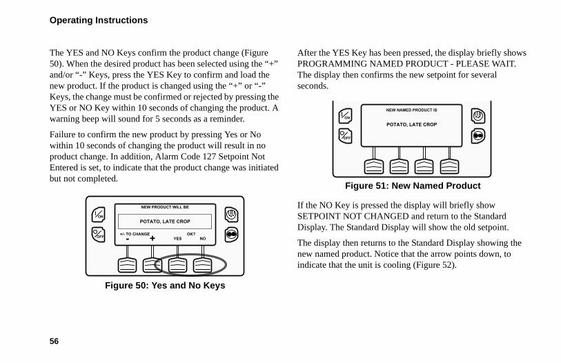
The YES and NO Keys confirm the product change (Figure 50). When the desired product has been selected using the “+” and/or “-” Keys, press the YES Key to confirm and load the new product. If the product is changed using the “+” or “-” Keys, the change must be confirmed or rejected by pressing the YES or NO Key within 10 seconds of changing the product. A warning beep will sound for 5 seconds as a reminder.
Failure to confirm the new product by pressing Yes or No within 10 seconds of changing the product will result in no product change. In addition, Alarm Code 127 Setpoint Not Entered is set, to indicate that the product change was initiated but not completed.
Figure 50: Yes and No Keys
After the YES Key has been pressed, the display briefly shows PROGRAMMING NAMED PRODUCT - PLEASE WAIT. The display then confirms the new setpoint for several seconds.
Figure 51: New Named Product
If the NO Key is pressed the display will briefly show SETPOINT NOT CHANGED and return to the Standard Display. The Standard Display will show the old setpoint.
The display then returns to the Standard Display showing the new named product. Notice that the arrow points down, to indicate that the unit is cooling (Figure 52).
- NO
NEW PRODUCT WILL BE
++/- TO CHANGE OK?YES
POTATO, LATE CROPON
OFF
NEW NAMED PRODUCT IS
POTATO, LATE CROPON
OFF

Operating Instructions
57
Figure 52: Standard Display
IMPORTANT: If the named product is changed using the “+” or “-” Keys, the change must be confirmed or rejected by pressing the YES or NO Key within 10 seconds of changing the named product.
• If the YES Key is pressed, the product change made with the “+” or “-” Key is accepted, the product changes, and the display returns to the Standard Display.
• If the NO Key is pressed the product change made with the “+” or “-” Key is not accepted, the product is not changed, and the display returns to the Standard Display.
• If the YES or NO Key is not pressed within 10 seconds of making a change with the “+” or “-” Key, the product is not changed and the display returns to the Standard Display. The display briefly shows [SETPOINT NOT CHANGED] and Alarm Code 127 Setpoint Not Entered is set, to indicate that the product change was initiated but not completed.
See Figure 53 for an overview of the Changing the Setpoint - Named Product procedure.
MENU45 °F
45PRODUCT SENSORSGAUGES
.8
POTATO, LATE CROP
ON
OFF

Operating Instructions
58
Figure 53: Changing the Setpoint, Named Product
ON
OFF MENU59 °F
59PRODUCT SENSORSGAUGES
.8
GRAPEFRUIT, ARIZONA
- EXIT
CURRENT PRODUCT IS
GRAPEFRUIT, ARIZONA
++/- TO CHANGE
ON
OFF
- NO
NEW PRODUCT WILL BE
++/- TO CHANGE OK?YES
POTATO, LATE CROPON
OFF
- NO
NEW PRODUCT WILL BE
++/- TO CHANGE OK?YES
POTATO, LATE CROPON
OFF
NEW NAMED PRODUCT IS
POTATO, LATE CROPON
OFF
MENU45 °F
45PRODUCT SENSORSGAUGES
.8
POTATO, LATE CROP
ON
OFF
Product Key
Setpoint Display
+ or - Keys
Yes or No Keys
If Yes Key Chosen,
Standard Display
New Named Product
Operating Instructions
59
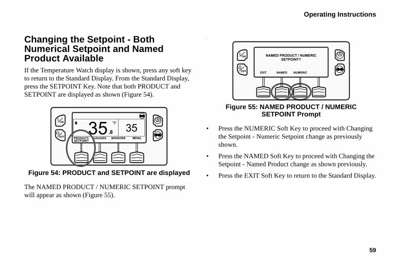
Changing the Setpoint - Both Numerical Setpoint and Named Product AvailableIf the Temperature Watch display is shown, press any soft key to return to the Standard Display. From the Standard Display, press the SETPOINT Key. Note that both PRODUCT and SETPOINT are displayed as shown (Figure 54).
Figure 54: PRODUCT and SETPOINT are displayed
The NAMED PRODUCT / NUMERIC SETPOINT prompt will appear as shown (Figure 55).
.
Figure 55: NAMED PRODUCT / NUMERIC SETPOINT Prompt
• Press the NUMERIC Soft Key to proceed with Changing the Setpoint - Numeric Setpoint change as previously shown.
• Press the NAMED Soft Key to proceed with Changing the Setpoint - Named Product change as shown previously.
• Press the EXIT Soft Key to return to the Standard Display.
ON
OFF MENU35 °F
35PRODUCT/ SENSORSGAUGESSETPOINT
.8
EXIT NAMED NUMERIC
NAMED PRODUCT / NUMERICSETPOINT?
ON
OFF

Operating Instructions
60
Starting the Diesel EngineDiesel engine preheats and starts are automatic in both Continuous Mode and Cycle Sentry Mode. The engine will preheat and start as required when the unit is turned on. The engine preheat and start will be delayed in Cycle Sentry Mode if there is no current need for the engine to run. If any keys are being pressed on the HMI Control Panel the engine will not preheat and start until 10 seconds after the last key is pressed.
NOTE: If the unit is equipped with optional Electric Standby there may be some additional prompts before the engine will start. See STARTING THE ELECTRIC MOTOR on the following pages for details.CAUTION: The engine may start automatically any time the unit is turned on.WARNING: Never use starting fluid.
When the engine is preparing to start the HMI Control Panel will display the engine start screen (Figure 56). The preheat buzzer sounds during the engine preheat and crank sequence.
Figure 56: Engine Start Screen
After the engine is started the display returns to the Standard Display of temperature and setpoint.
ON
OFF
DIESEL ENGINE STARTING

Operating Instructions
61
Starting the Electric MotorUnits equipped with the SmartPower option only.
Electric Power Receptacle: The electric power receptacle is used to connect the unit to an appropriate electric power source for electric standby operation (Figure 57). The electric power receptacle is usually mounted on the trailer below the HMI Control Panel. Make sure the unit and the power supply are turned off before connecting or disconnecting a power cord.
Electric motor starting is automatic in both Continuous Mode and Cycle Sentry Mode. The motor will start as required when the unit is turned on. If any keys are being pressed on the HMI Control Panel prior to the motor start, the motor start will be delayed until 10 seconds after the last key is pressed.CAUTION: The motor may start automatically any time the unit is turned on.
Figure 57: Electric Power Receptacle
When the motor is preparing to start the HMI Control Panel will display the motor start screen (Figure 58). The preheat buzzer sounds for 20 seconds before the electric motor starts.
Figure 58: Motor Start Screen
ELECTRIC MOTOR STARTINGON
OFF

Operating Instructions
62
Switching from Diesel to ElectricUnits equipped with the SmartPower option only.
If the Diesel to Electric Auto-Switch Enabled feature in Guarded Access is set YES then the unit will automatically switch to Electric Mode operation when standby power is connected and available.
If the Diesel to Electric Auto-Switch Enabled feature in Guarded Access is set NO then the prompt screen (Figure 59) will appear when standby power is connected and available.
Figure 59: Standby Power Connected
If NO is selected, then the unit will continue to operate in Diesel Mode. If YES is selected then the display will briefly show the screen in Figure 60.
Figure 60: YES Selected
Electric Mode operation will briefly be confirmed. If unit operation is required the electric motor will start as shown previously under STARTING THE ELECTRIC MOTOR.
If the Diesel to Electric Auto-Switch Enabled feature in Guarded Access is set NO then the unit can also be switched from Diesel Mode to Electric Mode operation using the Electric Standby Selection from the Main Menu as shown later in this section.
ON
OFF
ELECTRIC STANDBY DETECTED
DO YOU WISH TO SWITCH TO ELECTRIC?
NOYES
PROGRAMMING ELECTRIC
STANDBY
PLEASE WAIT
ON
OFF

Operating Instructions
63
Switching from Electric to DieselUnits equipped with the SMARTPOWER option only.
If the Electric to Diesel Auto-Switch Enabled feature in Guarded Access is set YES then the unit will automatically switch to Diesel Mode operation when standby power is turned off or is no longer available.
If the Electric to Diesel Auto-Switch Enabled feature in Guarded Access is set NO and standby power is disconnected or fails, the unit will not automatically switch to Diesel Mode. This is primarily designed to prevent unauthorized diesel engine starts when the truck is indoors or on a ferry where engine operation is strictly prohibited. If the Electric to Diesel Auto-Switch Enabled feature in Guarded Access is set NO then the prompt screen (Figure 61) will appear when standby power is turned off or is no longer available.
Figure 61: Standby Power is Off
If YES is selected then the display will briefly show the screen in Figure 62.
Figure 62: Yes Selected
ELECTRIC STANDBY NOT DETECTED
DO YOU WISH TO SWITCH TO DIESEL?
YES NO
ON
OFF
PROGRAMMING DIESEL MODE
PLEASE WAIT
ON
OFF

Operating Instructions
64
Diesel Mode operation will briefly be confirmed. If unit operation is required the diesel engine will start as shown previously under STARTING THE DIESEL ENGINE.
If the Electric to Diesel Auto-Switch Enabled feature in Guarded Access is set NO then the unit can also be switched from Diesel Mode to Electric Mode operation using the Diesel Selection from the Main Menu as shown later in this section.
Initiating a Manual Defrost CycleDefrost cycles are usually initiated automatically based on time or demand. Manual defrost is also available
Manual defrost is available if the unit is running and the evaporator coil temperature is less than or equal to 45 F (7 C).
NOTE: If the Rail Alternate feature is set YES defrost is allowed with an evaporator coil temperature less than or equal to 55 F (13 C).
Other features such as door switch settings may not allow manual defrost under some conditions. To initiate a manual defrost cycle, press the Defrost Key (Figure 63).
Figure 63: Press Defrost Key
The display briefly shows [DEFROST], [PROGRAMMING DEFROST - PLEASE WAIT] and then [DEFROST STARTED] (Figure 64).
Figure 64: Defrost Started
ON
OFF MENU35 °F
35SET SENSORSGAUGES
POINT
.8
DEFROST STARTEDON
OFF
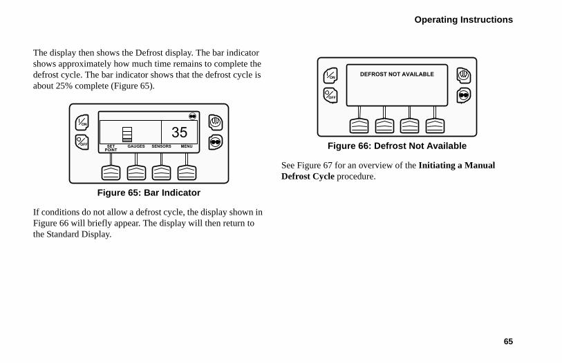
Operating Instructions
65
The display then shows the Defrost display. The bar indicator shows approximately how much time remains to complete the defrost cycle. The bar indicator shows that the defrost cycle is about 25% complete (Figure 65).
Figure 65: Bar Indicator
If conditions do not allow a defrost cycle, the display shown in Figure 66 will briefly appear. The display will then return to the Standard Display.
Figure 66: Defrost Not Available
See Figure 67 for an overview of the Initiating a Manual Defrost Cycle procedure.
35MENUSET SENSORSGAUGES
POINT
ON
OFF
ON
OFF
DEFROST NOT AVAILABLE
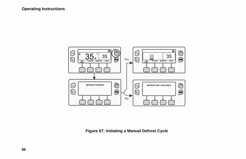
Operating Instructions
66
Figure 67: Initiating a Manual Defrost Cycle
ON
OFF MENU35 °F
35SET SENSORSGAUGES
POINT
.8
DEFROST STARTEDON
OFF
35MENUSET SENSORSGAUGES
POINT
ON
OFF
ON
OFF
DEFROST NOT AVAILABLE
No
Yes

Operating Instructions
67
Terminating a Defrost CycleThe defrost cycle terminates automatically when the coil temperature is greater than or equal to 58 F (14 C) or the defrost timer expires. Defrost can also be terminated by turning the unit off and back on.
NOTE: If Rail Alternate is set YES the defrost cycle terminates at 70 F (21 C) or if the defrost timer expires.
Selecting Cycle Sentry or Continuous ModeWhen Cycle Sentry Mode is selected the unit will start and stop automatically to maintain setpoint, keep the engine warm and the battery charged. When Continuous Mode is selected, the unit starts automatically and runs continuously to maintain setpoint and provide constant airflow.
IMPORTANT: Cycle Sentry or Continuous Mode may not be selectable if OptiSet Plus is in use.
See Figure 73 for an overview of the Selecting Cycle Sentry or Continuous Mode procedure.
If the unit is operating in Cycle Sentry Mode, the Cycle Sentry Icon will be present in the upper right corner of the display as shown below. If the Cycle Sentry Icon (Figure 68) is not present the unit is operating in Continuous Mode.
Figure 68: Cycle Sentry Icon
If allowed by OptiSet Plus, Cycle Sentry Mode or Continuous Mode is selected by pressing the Cycle Sentry/Continuous Key as shown in Figure 69.
ON
OFF MENU35 °F
35SET SENSORSGAUGES
POINT
.8

Operating Instructions
68
Figure 69: Cycle Sentry/Continuous Key
NOTE: Cycle Sentry Mode or Continuous Mode can also be selected using the Main Menu > Mode Submenu.
If the unit is in Cycle Sentry Mode, pressing the Cycle Sentry/Continuous Key changes the mode from Cycle Sentry Mode to Continuous Mode. The display confirms the change, as shown in Figure 70.
Figure 70: Continuous Mode
The new mode is confirmed for 3 seconds (Figure 71).
Figure 71: New Mode Confirmed
ON
OFF MENU35 °F
35SET SENSORSGAUGES
POINT
.8
ON
OFF
PROGRAMMING CONT MODE
PLEASE WAIT
ON
OFF
NEW SYSTEM MODE IS
CONTINUOUS
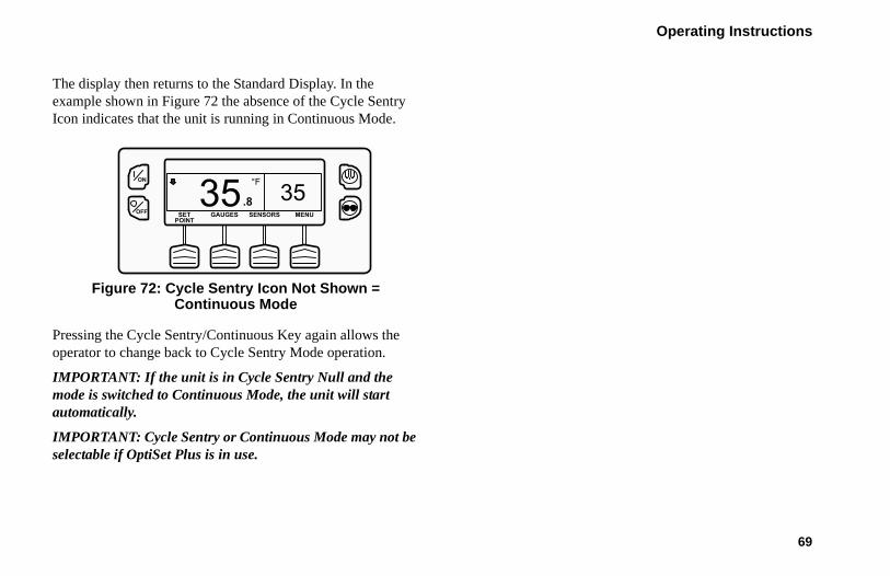
Operating Instructions
69
The display then returns to the Standard Display. In the example shown in Figure 72 the absence of the Cycle Sentry Icon indicates that the unit is running in Continuous Mode.
Figure 72: Cycle Sentry Icon Not Shown = Continuous Mode
Pressing the Cycle Sentry/Continuous Key again allows the operator to change back to Cycle Sentry Mode operation.
IMPORTANT: If the unit is in Cycle Sentry Null and the mode is switched to Continuous Mode, the unit will start automatically.
IMPORTANT: Cycle Sentry or Continuous Mode may not be selectable if OptiSet Plus is in use.
ON
OFF MENU35 °F
35SET SENSORSGAUGES
POINT
.8

Operating Instructions
70
Figure 73: Selecting Cycle Sentry or Continuous Mode
ON
OFF MENU35 °F
35SET SENSORSGAUGES
POINT
.8
ON
OFF MENU35 °F
35SET SENSORSGAUGES
POINT
.8
ON
OFF
PROGRAMMING CONT MODE
PLEASE WAIT
ON
OFF
NEW SYSTEM MODE IS
CONTINUOUS
ON
OFF MENU35 °F
35SET SENSORSGAUGES
POINT
.8
Continuous Mode Selected

Operating Instructions
71
Using the Gauges KeyThe GAUGES Key allows the operator to view the unit gauges. If the function of this key has been reassigned, the GAUGES Menu is also available in the Maintenance Menu.
To access the GAUGES Menu, press the GAUGES Key (Figure 74).
Figure 74: Gauges Key
The first gauge display will appear. Press the NEXT and BACK Keys to scroll through the gauges. Pressing the LOCK Key will lock the current gauge on the display (Figure 75).
Figure 75: Gauge Display Locked
The gauges and I/O conditions available are shown on the next page. Not all gauges or I/O conditions may appear depending on unit configuration and software revision.
To return to the Standard Display press the EXIT Key.
Gauges AvailableCoolant Temperature: Displays the temperature of the engine coolant.
Coolant Level: Displays the coolant level in the overflow tank.
Engine Oil Pressure: Displays the engine oil pressure as OK or LOW.
ON
OFF MENU35 °F
35SET SENSORSGAUGES
POINT
.8
ON
OFF
BATTERY VOLTAGE
13.8
NEXTEXIT LOCK BACK
v

Operating Instructions
72
Engine Oil Level Switch: Displays the engine oil level as OK or LOW.
Amps: Displays the current flow in amps flowing to or from the unit battery.
Battery Voltage: Displays the voltage of the unit battery.
Accessory Battery Voltage: Displays the voltage at the alternator.
Engine RPM: Displays the engine speed in RPMs.
Fuel Level Sensor: Displays the fuel level if a fuel level sensor is installed.
Discharge Pressure: Displays the unit discharge pressure. (ETV units only)
Suction Pressure: Displays the unit suction pressure. (ETV units only)
ETV Position: Displays the current position of the ETV valve. (ETV equipped units only)
Fresh Air Exchange: Displays the current position of the optional Fresh Air Exchange Door.
I/O (Input/Output State): Displays the current state of the input/output devices listed here:
• High Speed Relay/Electric Heat
• Spare Output 1
• Run Relay • Spare Output 2
• Run Relay Feedback • Spare Output 3
• Alternator Excite Output
• Spare Output 4
• Defrost Damper • Spare Output 5
• Heat Output • Fresh Air Exchange Output
• Motor RPM • Fresh Air Exchange Feedback
• Spare Digital Input 1 • Diesel/Electric Relay (SmartPower units only)
• Spare Digital Input 2 • Electric Ready Input (SmartPower units only)

Operating Instructions
73
Using The Sensors KeyThe SENSORS Key allows the operator to view the unit gauges. If the function of this key has been reassigned, the SENSORS Menu is also available in the Maintenance Menu.
To access the SENSORS Menu, press the SENSORS Key:
Figure 76: Sensors Key
The first sensor display will appear. Press the NEXT and BACK Keys to scroll through the sensors. Pressing the LOCK Key will lock the current sensor on the display. (Figure 77)
Figure 77: Next, Back, Lock Keys
• Spare Digital Input 3 • Electric overload (SmartPower units only)
• Spare Digital Input 4 • Hot Gas Bypass (ETV units only)
• Spare Analog Input 1
• Spare Analog Input 2
ON
OFF MENU35 °F
35SET SENSORSGAUGES
POINT
.8
CONTROL DISCHARGE AIR TEMPERATURE
48.NEXTEXIT LOCK
3 °F
BACK
ON
OFF

Operating Instructions
74
The sensors available are shown below.
To return to the Standard Display press the EXIT Key.
Sensors AvailableControl Return Air Temperature: Displays the temperature of the control return air sensor.
Display Return Air Temperature: Displays the temperature of the display return air sensor.
Control Discharge Air Temperature: Displays the temperature of the control discharge air sensor.
Display Discharge Air Temperature: Displays the temperature of the display discharge air sensor.
Temperature Differential: Displays the calculated difference between the control return air sensor and the control discharge air sensor.
Evaporator Coil Temperature: Displays the temperature of the evaporator coil sensor.
Ambient Air Temperature: Displays the temperature of the ambient air sensor.
* Spare 1 Temperature: Displays the temperature of the spare 1 temperature sensor.
* Log Sensor 1: Displays the temperature of the CargoWatch Data Logger temperature sensor 1.
* Log Sensor 2: Displays the temperature of the CargoWatch Data Logger temperature sensor 2.
* Log Sensor 3: Displays the temperature of the CargoWatch Data Logger temperature sensor 3.
* Log Sensor 4: Displays the temperature of the CargoWatch Data Logger temperature sensor 4.
* Log Sensor 5: Displays the temperature of the CargoWatch Data Logger temperature sensor 5.
* Log Sensor 6: Displays the temperature of the CargoWatch Data Logger temperature sensor 6.
Board Temperature Sensor: Displays the internal temperature of the HMI Control Panel pc board.
* If sensors have been added.

Operating Instructions
75
Using the Main MenuThe Main Menu contains several additional submenus that allow the operator to view information and modify unit operation. To access the Main Menu press the MENU Key (Figure 78).
Figure 78: Menu Key
The first Main Menu choice will appear. Press and hold the UP and DOWN Keys to scroll through the menu choices. When the desired selection is shown on the display, press the SELECT Key to access it. The Pretrip submenu is displayed (Figure 79).
To return to the Standard Display press the EXIT Key.
Figure 79: Pretrip Submenu
Main Menu Choices
Each of these Main Menu choices will be explained in following pages of this chapter:
Pretrip: A Pretrip Test verifies unit operation.
Flash Drive: If a properly configured USB Flash Drive is currently connected to the USB Port on the unit Control Panel, the Flash Drive Menu will appear as a Main Menu selection.
Languages (If Enabled): If more than one language is enabled from the Guarded Access > Language Menu, this menu item will appear.
MENU35 °F
35SET SENSORSGAUGES
POINT
.8
ON
OFF
ON
OFF
MAIN MENU
DOWNEXIT SELECT UP
PRETRIPLANGUAGEALARMSGAUGES

Operating Instructions
76
Alarms: The Alarm Menu allows the operator to view any active alarms, and allows most alarms to be cleared.
Gauges: The Gauges Menu allows the operator to view the unit gauges and I/O conditions.
Sensors: The Sensors Menu allows the operator to view the unit and CargoWatch Data Logger temperature sensors.
Data Logger (CargoWatch): The CargoWatch Data Logger is physically located in the HMI Control Panel. It can support up to 6 optional temperature sensors.
Hourmeters: The Hourmeters Menu allows the operator to view the unit hourmeters that have the view feature enabled in the Guarded Access menu.
Mode: The Mode Menu allows the operator to change the unit operating modes that have been enabled in Guarded Access.
Keypad Lockout: If enabled in Guarded Access > Main Menu Configuration, the keypad can be locked to prevent unauthorized use.
Start Sleep Mode: If this feature enabled in Guarded Access > Main Menu Configuration, the operator can select and set Sleep Mode from the Mode Menu.
SmartPower™ Electric Standby Option: The Diesel/Electric Standby selection from the Main Menu allows the operator to manually select Diesel or Electric Mode operation on units equipped with the electric standby SmartPower option.
Adjust Brightness: The brightness of the HMI Control Panel display can be adjusted to allow for changing ambient light conditions.
Time: The Time and Date held by the HMI Control Panel can be checked. Time and Date cannot be changed from the Main Menu.
Clear All ECU Faults: Pressing this key will clear all existing Engine Control Unit (ECU) Fault Codes.
PretripPretrip Test verifies unit operation. This display allows a Pretrip Test to be selected and initiated by the operator. If the Pretrip Test is entered with the unit shut down a Full Pretrip Test with device amp checks will be performed. If the Pretrip Test is entered with the unit running in either Diesel or Electric
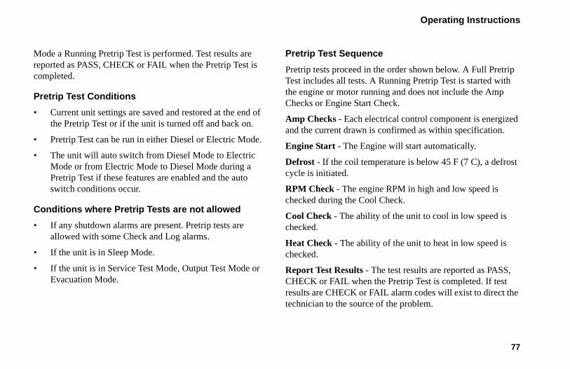
Operating Instructions
77
Mode a Running Pretrip Test is performed. Test results are reported as PASS, CHECK or FAIL when the Pretrip Test is completed.
Pretrip Test Conditions
• Current unit settings are saved and restored at the end of the Pretrip Test or if the unit is turned off and back on.
• Pretrip Test can be run in either Diesel or Electric Mode.
• The unit will auto switch from Diesel Mode to Electric Mode or from Electric Mode to Diesel Mode during a Pretrip Test if these features are enabled and the auto switch conditions occur.
Conditions where Pretrip Tests are not allowed
• If any shutdown alarms are present. Pretrip tests are allowed with some Check and Log alarms.
• If the unit is in Sleep Mode.
• If the unit is in Service Test Mode, Output Test Mode or Evacuation Mode.
Pretrip Test Sequence
Pretrip tests proceed in the order shown below. A Full Pretrip Test includes all tests. A Running Pretrip Test is started with the engine or motor running and does not include the Amp Checks or Engine Start Check.
Amp Checks - Each electrical control component is energized and the current drawn is confirmed as within specification.
Engine Start - The Engine will start automatically.
Defrost - If the coil temperature is below 45 F (7 C), a defrost cycle is initiated.
RPM Check - The engine RPM in high and low speed is checked during the Cool Check.
Cool Check - The ability of the unit to cool in low speed is checked.
Heat Check - The ability of the unit to heat in low speed is checked.
Report Test Results - The test results are reported as PASS, CHECK or FAIL when the Pretrip Test is completed. If test results are CHECK or FAIL alarm codes will exist to direct the technician to the source of the problem.

Operating Instructions
78
Pretrip Test Considerations
When performing a Pretrip Test, the following issues should be considered.
• If running a Pretrip Test on a trailer loaded with dry cargo, insure that proper airflow can occur around the load. If the load restricts airflow, false test results may occur. Also, Precedent units have high refrigeration capacity which results in rapid temperature changes. Sensitive dry cargo may be damaged as a result.
• If running a Pretrip Test on a trailer that has just been washed down, the extremely high humidity inside the trailer may result in false test results.
• If running a Pretrip Test on a trailer loaded with sensitive cargo, monitor the load temperature during the test as normal temperature control is suspended during pre-trip operation.
• Always perform Pretrip Tests with the trailer cargo doors closed to prevent false test failures.
Performing a Pretrip TestIf a Pretrip Test is initiated with the engine shut down a Full Pretrip Test will be performed. If a Pretrip Test is initiated with the engine or motor running a Running Pretrip Test is performed.
• Before initiating a Pretrip Test, clear all alarm codes.
• To stop a Pretrip Test at any time turn the unit off.
Pretrip Tests are initiated using the Pretrip Menu. From the Standard Display, press the MENU Key (Figure 80).
Figure 80: Menu Key
MENU35 °F
35SET SENSORSGAUGES
POINT
.8
ON
OFF

Operating Instructions
79
The Main Menu will appear. Press the UP or DOWN Key as required to choose the Pretrip Menu. When the Pretrip Menu is shown press the SELECT Key to start a Pretrip Test (Figure 81).
Figure 81: Select Key
The display will briefly show PROGRAMMING PRETRIP MODE (Figure 82). If the unit is not running a Full Pretrip Test will be initiated. If the unit is running in either Diesel or Electric Mode a Running Pretrip Test will be performed.
Figure 82: Programming Trip Mode
If all alarms were not cleared a prompt appears (Figure 83). Exit the Pretrip Test, clear all alarms and repeat the Pretrip Test.
Figure 83: Alarms Not Cleared
ON
OFF
MAIN MENU
DOWNEXIT SELECT UP
PRETRIPLANGUAGEALARMSGAUGES
ON
OFF
PROGRAMMING PRETRIP MODE
NO PRETRIP -- ALARM ACTIVE
EXIT
ON
OFF

Operating Instructions
80
If all alarms were cleared, the Pretrip Test display appears (Figure 84).
Figure 84: Pretrip Test
• The top line of the display indicates the unit is performing the non-running portion of the Pretrip Test.
• The second line measures test progress. The number of tests completed of the total number of tests to be performed is shown. In the example above the unit is performing Test 1 of 26, Sensor Check.
• The soft keys may be used during the Pretrip Test to select the Hourmeter, Gauge or Sensor menus.
• To stop a Pretrip Test at any time turn the unit off. This will generate Alarm Code 28 Pretrip Abort. Other alarm codes may also be generated. This is normal when the Pretrip Test is halted before completion.
When the non-running tests are complete the unit will start automatically and continue with the Running Pretrip Test. In the example shown in Figure 85 the unit is in the Running Pretrip and is performing Test 21 of 26, Cool Test.
Figure 85: Cool Test
When all tests are complete, the results are reported as PASS, CHECK or FAIL (Figure 86). If the results are CHECK or FAIL, the accompanying alarm codes will direct the technician to the cause of the problem.
HOURMETERS
TEST 1 OF 26SENSOR CHECK
SENSORS GAUGES
NON-RUNNING PRETRIP
ON
OFF
TEST 21 OF 26COOL TEST
RUNNING PRETRIP
HOURMETERS
SENSORS GAUGES
ON
OFF

Operating Instructions
81
Figure 86: Pretrip Pass
If the Pretrip Test results are CHECK or FAIL the problem should be diagnosed and corrected by a Thermo King service technician before the unit is released for service.
To return to the Main Menu press the EXIT Key. To return to the Standard display press the EXIT Key again.
See Figure 87 for an overview of the Performing a Pretrip Test procedure.
EXIT
PRETRIPPASSON
OFF

Operating Instructions
82
Figure 87: Performing a Pretrip Test
MENU35 °F
35SET SENSORSGAUGES
POINT
.8
ON
OFF
ON
OFF
MAIN MENU
DOWNEXIT SELECT UP
PRETRIPLANGUAGEALARMSGAUGES
ON
OFF
PROGRAMMING PRETRIP MODE
NO PRETRIP -- ALARM ACTIVE
EXIT
ON
OFF
HOURMETERS
TEST 1 OF 26SENSOR CHECK
SENSORS GAUGES
NON-RUNNING PRETRIP
ON
OFF
TEST 21 OF 26COOL TEST
RUNNING PRETRIP
HOURMETERS
SENSORS GAUGES
ON
OFF
EXIT
PRETRIPPASSON
OFF
Alarms Cleared?No
Yes
Exit Pretrip Test, clear alarms,restart Pretrip Test.

Operating Instructions
83
Flash DriveIf a properly configured USB Flash Drive is currently connected to the USB Port on the unit Control Panel, the Flash Drive Menu will appear as a Main Menu selection. If a properly configured USB Flash Drive is connected to the USB Flash Drive connector, this feature allows the operator to select the desired Flash Drive function. If enabled when the Flash Drive was configured, the following functions may be available:
Download
• Download the ServiceWatch Data Logger
• Download the CargoWatch Data Logger
Flashload
• Flash load Base Controller Software
• Flash load HMI Control Panel Software
OptiSet Plus
• SEND
• Send OptiSet Plus files
• RETRIEVE
• Retrieve OptiSet Plus files
If a USB Flash Drive is not connected to the unit, this feature will not appear in the Main Menu.
Flash Drive Icon•“The USB Icon (Figure 88) will appear in the upper left corner of the display as shown below when a USB Flash Drive is inserted in the USB Flash Drive USB Port on the Unit Control Panel.
•“The USB Icon will also appear if a computer is connected to the USB PC Computer USB Port on the Unit Control Panel.
Figure 88: Flash Drive Icon
ON
OFF MENU35 °F
35SET SENSORSGAUGES
POINT
.8

Operating Instructions
84
Selecting the Flash Drive Menu from the Main Menu (If Already Connected)To select the Flash Drive Menu, press the MENU Key (Figure 89). The Main Menu will appear.
Figure 89: Menu Key
If a properly configured USB Flash Drive is connected to the Flash Drive Only USB Port on the Control Panel, the Flash Drive Menu will appear as a main Menu selection. Press the UP or DOWN Key as required to choose the Flash Drive Menu. When the Flash Drive Menu is shown press the SELECT Key to select the Flash Drive menu. (Figure 90).
Figure 90: Flash Drive Menu
Flash Drive (If Connected While the Unit is Turned On)
If a properly configured USB Flash Drive is connected to the USB Port on the unit Control Panel while the unit is turned on, a Flash Drive indication will appear for several seconds. Then the Flash Drive Menu will be shown (Figure 91).
MENU35 °F
35SET SENSORSGAUGES
POINT
.8
ON
OFF
ON
OFF
MAIN MENU
DOWNEXIT SELECT UP
FLASH DRIVEPRETRIPLANGUAGESALARMS

Operating Instructions
85
Figure 91: Flash Drive
Removing the Flash Drive If the Flash Drive is disconnected, the display shown in Figure 92 will appear for 30 seconds and the display will return to the Standard Display. To return to the Standard Display immediately press the EXIT Soft Key.
Figure 92: Flash Drive Removed
If the HELP Soft Key is pressed the display shown in Figure 93 will appear.
Figure 93: Help Soft Key Pressed
ON
OFF
FLASH DRIVE DETECTED
LOAD LOAD PLUSEXIT DOWN FLASH OPTISET
ON
OFF
FLASH DRIVE REMOVED
EXIT HELP
ON
OFF EXIT
FLASH DRIVE REMOVED
PLEASE CHECK THE FLASH DRIVE FORPROPER INSERTION – REMOVE AND
REINSERT

Operating Instructions
86
Languages (If Enabled)If more than one language is enabled from the Guarded Access > Language Menu, this menu item will appear. If only one language is enabled, this menu will not appear. The Language Menu allows the operator to select a language from of enabled languages. All subsequent displays are shown in the selected language. English is the default language. See the Guarded Access Language Setup Menu in the Diagnostic Manual for technical details.
If Languages are not enabled from the Guarded Access Menu, this feature will not appear in the Main Menu.
IMPORTANT: Exercise care when changing languages, as once changed all HMI Control Panel displays will be in the new language.
Available LanguagesThe following languages are available:
Selecting an Alternate Language
To select an alternate language, press the MENU Key (Figure 94).
Figure 94: Menu Key
The Main Menu will appear. If more than one language is enabled, the Language Menu will appear as a main Menu selection (Figure 95). Press the UP or DOWN Key as required to choose the Language Menu. When the Language Menu is shown press the SELECT Key to select the Language menu.
• English • French • Spanish
MENU35 °F
35SET SENSORSGAUGES
POINT
.8
ON
OFF

Operating Instructions
87
Figure 95: Main Menu
The Language menu will appear as shown in Figure 96. Press the + or - Keys to select the desired language. Only languages enabled from the Guarded Access Menu are available. When the desired language is shown (example is Español [Spanish]) press the YES Key to confirm the choice.
Figure 96: Language Menu
The display will briefly show PROGRAMMING LANGUAGE - PLEASE WAIT in the new language. The display will then return to the Language Menu, but will show the new language. Español (Spanish) is shown in Figure 97.
Figure 97: New Language (Example: Español)
Repeat the process to select a different language. To select a different Main Menu item press the NEXT (SIGUIENTE) Key. To return to the Standard Display press the EXIT (SALIDA) Key.
All displays will now be in the new language. Español (Spanish) is shown in Figure 98.
ON
OFF
MAIN MENU
DOWNEXIT SELECT UP
PRETRIPLANGUAGEALARMSGAUGES

Operating Instructions
88
Figure 98: New Language (Example: Español)
To return to the Main Menu press the EXIT Key. To return to the Standard display press the EXIT Key again.
See Figure 99 for an overview of the Languages selection procedure.

Operating Instructions
89
Figure 99: Languages (If Enabled)
MENU35 °F
35SET SENSORSGAUGES
POINT
.8
ON
OFF
ON
OFF
MAIN MENU
DOWNEXIT SELECT UP
PRETRIPLANGUAGEALARMSGAUGES
NEW LANGUAGE WILL BE
DEUTSCH
- YES NO+USE +/- TO CHANGE OK?
ON
OFF
ON
OFF
HAUPTMENU
SPRACHE
BEENDEN WEITERAUSWHAL
MENU35 °F
35SET SENSOREMESSGE
POINT
.8RAT N
ON
OFF

Operating Instructions
90
Language Menu Quick AccessShould it be necessary at any time to change to English or any other installed language, return to the Standard Display and then press and hold the first and last soft keys for 5 seconds as shown below. The Standard Display shown in Figure 100 is Español (Spanish).
Figure 100: Standard Display in Español
After 5 seconds the Language Menu will appear in the current language as shown below. Press the + or - Keys to select the desired language. When the desired language is shown press the SI (YES) Key to confirm the choice (Figure 101).
Figure 101: Select Desired Language
NOTE: All languages in the installed software can be selected using this method.
AlarmsThe Alarm Menu allows the operator to view any active alarms, and allows most alarms to be cleared.
Log AlarmsIf only Log Alarms exist the display shown in Figure 102 will appear and the optional remote alarm light will light for 30 seconds when the unit is turned on.

Operating Instructions
91
Figure 102: Log Alarms Exist
Check AlarmsIf a Check Alarm condition occurs while the unit is running the alarm icon will appear in the display as shown in Figure 103.
Figure 103: Alarm Icon
Shutdown AlarmsIf a Shutdown Alarm occurs while the unit is running it will be indicated by all of the following (Figure 104):
• The Alarm Icon will appear.
• The display, backlight and optional remote alarm light will flash on and off.
• The display will switch from normal video to reverse video and back to normal video. (Light areas become dark and dark areas become light.)
Figure 104: Reverse/Normal Video
ON
OFF
LOG ALARMS ACTIVE
GO TO MENU TO VIEW
EXIT
MENU35 35
SET SENSORSGAUGESPOINT
ON
OFF
MENU35 35
SET SENSORSGAUGESPOINT
ON
OFF

Operating Instructions
92
Pretrip AlarmsIf an alarm occurs during a Pretrip Test the alarm code will be displayed as Pretrip Alarm XX, where XX is the alarm code.
Alarm Codes When Switching Between Diesel and Electric Mode
If a shutdown alarm occurs that affects only Diesel Mode operation and the unit is switched to electric, the Diesel Mode shutdown alarm becomes an Electric Mode log alarm. This allows the unit to run in Electric Mode without clearing the shutdown alarm that is preventing Diesel Mode operation. If the unit is switched back to Diesel Mode, the alarm again become a Diesel Mode shutdown alarm and prevents unit operation.
In the same manner, if a shutdown alarm occurs that affects only Electric Mode operation and the unit is switched to diesel, the Electric Mode shutdown alarm becomes a Diesel Mode log alarm to allow Diesel Mode operation. If the unit is switched back to Electric Mode, the alarm reverts to an Electric Mode shutdown alarm and prevents unit operation. If the unit is configured for electric to diesel Auto-Switch, it automatically starts and runs in Diesel Mode if an electric shutdown occurs.
Clearing Alarm CodesMost alarm codes can be cleared conventionally from the Alarm Menu using the CLEAR Key.
The following control and display sensor alarm codes can only be cleared from the Maintenance Menu or Guarded Access Menu:
• Alarm Code 03 Check Control Return Air Sensor
• Alarm Code 04 Check Control Discharge Air Sensor
• Alarm Code 203 Check Display Return Air Sensor
• Alarm Code 204 Check Display Discharge Air Sensor
The following alarm codes clear automatically:
• Alarm Code 64 Pretrip Reminder - Clears when a Pretrip Test is performed.
• Alarm Code 84 Restart Null - Clears when the unit is no longer in a restart null due to a Prevent Alarm.
• Alarm Code 85 Forced Unit Operation - Clears when the unit is no longer running in a forced mode due to a Prevent Alarm.

Operating Instructions
93
• Alarm Code 91 Check Electric Ready Input - Clears automatically when the unit starts running.
• Alarm Code 92 Sensor Grades Not Set - Clears when the sensor grade is changed from 5H.
If the Limited Alarm Restarts feature is enabled the following additional alarm codes may only be cleared from the Guarded Access Menu. If this is the case, the CLEAR soft key will not appear if the alarms are displayed from the Main Menu or the Maintenance Menu.
• Alarm Code 10 High Discharge Pressure
• Alarm Code 23 Cooling Cycle Fault
• Alarm Code 24 Heating Cycle Fault
• Alarm Code 32 Refrigeration Capacity Low
Displaying and Clearing Alarm CodesAlarms are displayed and cleared using the Alarm Menu. From the Standard Display, press the MENU Key (Figure 105).
Figure 105: Menu Key
The Main Menu will appear. Press the UP or DOWN Key as required to choose the Alarms Menu (Figure 106). When the Alarms Menu is shown press the SELECT Key to select the Alarms menu.
Figure 106: UP/Down, Select Keys
MENU35 35
SET SENSORSGAUGESPOINT
ON
OFF
ON
OFF
MAIN MENU
DOWNEXIT SELECT UP
PRETRIPLANGUAGEALARMSGAUGES

Operating Instructions
94
The number of alarms (if more than one) and a list of the alarms with the most recent alarm first will be shown. In the example below, there are two alarms. The most recent is Alarm Code 5 Check Ambient Temp Sensor (Figure 107).
Figure 107: Alarms Menu
If necessary to view all alarms, scroll down using the DOWN Key (Figure 108).
Figure 108: Down Key
If the alarm situation has been resolved press the CLEAR Key to clear the alarm (Figure 109).
Figure 109: Clear Key
1 OF 2 ALARMS
DOWNEXIT CLEAR HELP
5
64
x
PRETRIP REMINDER
64
CHECK AMBIENT TEMP SENSORON
OFF
1 OF 2 ALARMS
DOWNEXIT CLEAR HELP
5
64
x
PRETRIP REMINDER
64
CHECK AMBIENT TEMP SENSORON
OFF
1 OF 2 ALARMS
DOWNEXIT CLEAR HELP
5
64
x
PRETRIP REMINDER
64
CHECK AMBIENT TEMP SENSORON
OFF

Operating Instructions
95
The display will briefly show CLEARING ALARM 5 – PLEASE WAIT. Then the Alarm Menu will reappear (Figure 110).
Note that Alarm Code 64 Pretrip Reminder cannot be cleared using the CLEAR Key. This alarm will clear automatically when a Pretrip Test is run.
Figure 110: Pretrip Reminder
If a serious condition occurs, the unit will be shut down to prevent damage to the unit or the load. If this occurs, the Alarm Icon will appear, the display and backlight will flash on and off. (Figure 111)
Figure 111: Unit Shutdown
The Alarm Menu display will display the Shutdown Alarm Code. For additional information regarding the alarm shown on the display, press the HELP Key (Figure 112).
Figure 112: Help Key
ON
OFF
1 OF 1 ALARMS
DOWNEXIT CLEAR HELP
64
x 64
PRETRIP REMINDER
MENU35 35
SET SENSORSGAUGESPOINT
ON
OFF
ON
OFF
1 OF 1 ALARMS
DOWNEXIT CLEAR HELP
66
x 64
LOW ENGINE OIL LEVEL

Operating Instructions
96
A help message will appear. Press the EXIT Key to return to the Alarms Menu (Figure 113). Check the oil level and add oil as required, clear the alarm and restart the engine.
Figure 113: Exit Key
To return to the Main Menu press the EXIT Key. To return to the Standard display press the EXIT Key again.
Important Alarm Notes
• If an alarm will not clear, it may still exist. If the alarm is not corrected, it will not clear or may be immediately set again.
• If an alarm cannot be cleared from the Main menu, the Clear Key will not appear. These alarms must be cleared from the Maintenance or Guarded Access Menus.
See Figure 114 for an overview of the Displaying and Clearing Alarm Codes procedure.
ON
OFF
CHECK ENGINE OIL LEVEL. IF UNIT IS SHUT DOWN REPAIR IMMEDIATELY. OTHERWISE
REPORT ALARM AT END OF DAY.
LOW ENGINE OIL LEVEL
EXIT

Operating Instructions
97
Figure 114: Displaying and Clearing Alarm Codes
ON
OFF
LOG ALARMS ACTIVE
GO TO MENU TO VIEW
EXIT
MENU35 35
SET SENSORSGAUGESPOINT
ON
OFF
MENU35 35
SET SENSORSGAUGESPOINT
ON
OFF
MENU35 35
SET SENSORSGAUGESPOINT
ON
OFF
ON
OFF
MAIN MENU
DOWNEXIT SELECT UP
PRETRIPLANGUAGEALARMSGAUGES
1 OF 2 ALARMS
DOWNEXIT CLEAR HELP
5
64
x
PRETRIP REMINDER
64
CHECK AMBIENT TEMP SENSORON
OFF
1 OF 2 ALARMS
DOWNEXIT CLEAR HELP
5
64
x
PRETRIP REMINDER
64
CHECK AMBIENT TEMP SENSORON
OFF
1 OF 2 ALARMS
DOWNEXIT CLEAR HELP
5
64
x
PRETRIP REMINDER
64
CHECK AMBIENT TEMP SENSORON
OFF
ON
OFF
1 OF 1 ALARMS
DOWNEXIT CLEAR HELP
64
x 64
PRETRIP REMINDER
MENU35 35
SET SENSORSGAUGESPOINT
ON
OFF
ON
OFF
CHECK ENGINE OIL LEVEL. IF UNIT IS SHUT DOWN REPAIR IMMEDIATELY. OTHERWISE
REPORT ALARM AT END OF DAY.
LOW ENGINE OIL LEVEL
EXIT
ON
OFF
1 OF 1 ALARMS
DOWNEXIT CLEAR HELP
66
x 64
LOW ENGINE OIL LEVEL

Operating Instructions
98
GaugesThe Gauges Menu allows the operator to view the unit gauges and I/O conditions. The unit gauges can always be viewed from the Main Menu. This is necessary if the GAUGES Soft Key on the Standard Display has been reassigned to a different function.
Displaying Gauges Gauges are displayed using the Gauges Menu. From the Standard Display, press the MENU Key (Figure 115).
Figure 115: Menu Key
The Main Menu will appear. Press the UP or DOWN Key as required to choose the Gauges Menu. When the Gauges Menu is selected, press the SELECT Key to choose the Gauges menu (Figure 116).
Figure 116: Up, Down, Select Keys
The first gauge display will appear. Press the NEXT and BACK Keys to scroll through the gauges and I/O conditions. Pressing the LOCK Key will lock the current gauge on the display (Figure 117).
MENU35 °F
35SET SENSORSGAUGES
POINT
.8
ON
OFF
ON
OFF
MAIN MENU
DOWNEXIT SELECT UP
PRETRIPLANGUAGEALARMSGAUGES

Operating Instructions
99
Figure 117: Next, Back, Lock Keys
The gauges and I/O conditions available are described in this section of the manual. Not all gauges or I/O conditions may appear depending on unit configuration and software revision.
To return to the Main Menu press the EXIT Key. To return to the Standard display press the EXIT Key again.
SensorsThe Sensors Menu allows the operator to view the unit and CargoWatch Data Logger temperature sensors. The sensors can always be viewed from the Main Menu. This is necessary if the SENSORS Soft Key on the Standard Display has been reassigned to a different function.
Displaying Sensors Sensors are displayed using the Sensors Menu. From the Standard Display, press the MENU Key (Figure 118).
Figure 118: Menu Key
The Main Menu will appear. Press the UP or DOWN Key as required to choose the Sensors Menu. When the Sensors Menu is selected, press the SELECT Key to choose the Sensors menu.
The first sensors display will appear. Press the NEXT and BACK Keys to scroll through the gauges and I/O conditions. Pressing the LOCK Key will lock the current gauge on the display (Figure 119).
ON
OFF
BATTERY VOLTAGE
13.8
NEXTEXIT LOCK BACK
v
MENU35 °F
35SET SENSORSGAUGES
POINT
.8
ON
OFF

Operating Instructions
100
Figure 119: Next, Back, Lock Keys
The sensors available are described in this section of the manual.
To return to the Main Menu press the EXIT Key. To return to the Standard display press the EXIT Key again.
Data Logger (CargoWatch)The CargoWatch Data Logger is physically located in the HMI Control Panel. It can support up to 6 optional temperature sensors.
When shipped from the factory, CargoWatch sensors 1 and 2 are turned on to be logged and CargoWatch sensors 3 through 6 are turned off. Also, digital input 1 is turned on to be logged and digital inputs 2 through 4 are turned off. Sensors and digital inputs can be turned on, off and configured using the CargoWatch menu in Guarded Access or with Wintrac. The CargoWatch Data Logger can also be configured using the USB Flash Drive OptiSet Plus Feature.
A Start of Trip can be sent to the unit ServiceWatch and CargoWatch Data Loggers. In addition, the CargoWatch Data Logger contents can be printed with a hand-held printer.
The ServiceWatch and CargoWatch Data Logger are accessed using the Data Logger Menu. From the Standard Display, press the MENU Key (Figure 120).
CONTROL DISCHARGE AIR TEMPERATURE
48.NEXTEXIT LOCK
3 °F
BACK
ON
OFF

Operating Instructions
101
Figure 120: Standard Screen, Menu Key
The Main Menu will appear. Press the UP or DOWN Key as required to choose the Data Logger Menu. When the Data Logger Menu is selected, press the SELECT Key to choose the Data Logger menu (Figure 121).
Figure 121: UP, Down, Select Keys
The Data Logger Menu will appear.
Sending Start of Trip Marker to CargoWatch and ServiceWatch Data LoggersTo send a Start of Trip marker to the CargoWatch and ServiceWatch Data Loggers press the SELECT Key. The display will briefly show START OF TRIP COMPLETE to confirm that a Start of Trip marker was set in the CargoWatch Data Logger (Figure 122).
Figure 122: Select Key, Start of Trip Complete
NOTE: The start of trip marker is sent to both the CargoWatch and ServiceWatch data loggers.
MENU35 °F
35SET SENSORSGAUGES
POINT
.8
ON
OFF
ON
OFF
MAIN MENU
DOWNEXIT SELECT UP
GAUGESSENSORSDATA LOGGERHOURMETERS
ON
OFF
DATA LOGGER
DOWNEXIT SELECT UP
START TRIPPRINT/VIEW

Operating Instructions
102
Printing CargoWatch Data Logger ReportsPress the DOWN Key to select the PRINT / VIEW feature and press the SELECT Key to choose Print/View.
The Print Data Menu will appear. The first Print Data Menu allows the operator to print a Delivery Ticket using a hand held printer. Pressing the SELECT Key will print the ticket (Figure 123). The Delivery Ticket is a short ticket that shows delivery specific details including the current temperature. A sample Delivery Ticket is shown in Figure 124.
Figure 123: Select Key, Print Delivery Ticket
Figure 124: Sample Delivery Ticket
Pressing the DOWN Key allows the operator to print a Trip Ticket using a hand held printer. Press the SELECT Key to print the ticket (Figure 125). The Trip Ticket is a long ticket that shows details for the current trip including a temperature history. The Trip Ticket is also called a Journey Ticket. A sample Trip Ticket is shown in Figure 126.
PRINT DATA
DOWNEXIT SELECT UP
DELIVERY TICKETTRIP TICKET
ON
OFF
CONTROLLER VERSION NUMBER:CONTROLLER TYPE:
TEMPERATURE UNITS:DATALOGGER VERSION NUMBER:
START:FINISH:SENSORS:SETPOINT:
B007SR26512
FAHRENHEIT05/30/08 08:29:0805/30/08 09:18:33
232.0
Sensor Min Ave Max Last#1: 35 35 35 35
SENSOR #1: LOG SENSOR 1SENSOR #2: LOG SENSOR 2
#2: - - - - - - - - - - - -

Operating Instructions
103
Figure 125: Select Key, Print Trip Ticket
Figure 126: Sample Trip Ticket
PRINT DATA
DOWNEXIT SELECT UP
DELIVERY TICKETTRIP TICKET
ON
OFF
UNIT SERIAL NUMBER:CONTROLLER SERIAL NUMBER:
CONTROLLER VERSION NUMBER:TRAILER ID:
CONTROLLER TYPE:
TEMPERATURE UNITS:DATALOGGER VERSION NUMBER:
START:FINISH:SENSORS:SETPOINT:
xxxxxxxxxxA00021506190T3
xxxxxxxxxxB007SR26512
FAHRENHEIT05/30/08 09:50:0805/30/08 13:07:33
132.0
SENSOR #1: LOG SENSOR 1SENSOR #2: LOG SENSOR 2
30 - MAY - 20081305 35.01250 35.21235 35.11220 35.21205 35.1
1150 35.01135 35.0
30 - MAY - 2008
1120 35.01105 34.91050 35.01035 35.01020 35.01005 35.10950 35.1

Operating Instructions
104
HourmetersThe Hourmeters Menu allows the operator to view the unit hourmeters that have the view feature enabled in the Guarded Access menu. If the view feature for a particular hourmeter is not enabled then that hourmeter will continue to accumulate time but cannot be viewed from the Main Menu. However, all hourmeters can be viewed from the Maintenance Menu, even if they are not enabled. The hourmeters shown below are implemented.
Viewing HourmetersOnly Hourmeters that have been enabled in Guarded Access are shown from the Main Menu. The Hourmeters can be viewed only.
Hourmeters are displayed using the Hourmeter Display. From the Standard Display, press the MENU Key (Figure 127).
Figure 127: Menu Key
The Main Menu will appear. Press the UP or DOWN Key as required to choose the Hourmeter Menu. When the Hourmeter Menu is selected, press the SELECT Key to choose the Hourmeter Menu (Figure 128).
Figure 128: Select Key
MENU35 °F
35SET SENSORSGAUGES
POINT
.8
ON
OFF
ON
OFF
MAIN MENU
DOWNEXIT SELECT UP
SENSORSDATA LOGGERHOURMETERSMODE

Operating Instructions
105
Press the NEXT or PREVIOUS Key to scroll through the hourmeters (Figure 129).
Figure 129: Up/Down Keys
Hourmeter names and definitions are shown in the table on the next page in the order they appear. Only hourmeters enabled in the Guarded Access Menu will be shown. To return to the Standard Display, press the EXIT Key.
When shipped from the factory, only these hourmeters are enabled for viewing from the Main Menu.
• Total Unit Run Hours
• Total Engine Run Hours
• Total Electric Run Hours
To return to the Main Menu press the EXIT Key. To return to the Standard display press the EXIT Key again.
Hourmeter Names and DefinitionsOnly configured hourmeters that have been enabled in the Viewable Hourmeter Setup Menu will be shown:
ON
OFF
HOURMETERS
DOWNEXIT SELECT UP
TOTAL UNIT RUN HOURSTOTAL ENGINE RUN HOURS
833TOTAL ELECTRIC RUN HOURS
Hourmeter Name
Definition
Total Hours Total number of hours the unit has been turned on (protection hours).
Total Run Time Hours
Total number of hours the unit has run in both diesel and Electric Mode.
Engine Hours Total number of hours the unit has run in Diesel Mode.
Electric Run Hours
Total number of hours the unit has run in Electric Mode.
Total Run Reminder 1
User Programmable - The number of hours before a Total Unit Run Time Maintenance Reminder 1 occurs.

Operating Instructions
106
IMPORTANT: If a programmable hourmeter is not enabled or the view for that hourmeter is not turned on it will not appear in the display sequence.
Mode MenuThe Mode Menu allows the operator to change the unit operating modes that have been enabled in Guarded Access. Only Operating Modes that have been enabled from the Guarded Access > Main Menu Configuration Menu will be shown.
• Turns Off Cycle Sentry Mode/Turns On Cycle Sentry Mode (If Cycle Sentry is turned Off unit runs in Continuous). Note that selecting Cycle Sentry Mode or Continuous Mode can also be accomplished using the Cycle Sentry Key to the right of the display.
• Allows temperature to be displayed in either Fahrenheit or Celsius degrees (if enabled from the Guarded Access > Main Menu Configuration Menu).
• Allows the optional Fresh Air Exchange door to be opened or closed (if enabled from the Guarded Access > Hardware Configuration Menu).
Total Run Reminder 2
User Programmable - The number of hours before a Total Unit Run Time Maintenance Reminder 2 occurs.
Controller Power On
Total hours the controller and HMI Control Panel have been turned on.
Pretrip Reminder
User Programmable - number of hours before a Pretrip Reminder occurs.
Engine Reminder 1
User Programmable - The number of hours before an Engine Run Time Maintenance Reminder 1 occurs.
Engine Reminder 2
User Programmable - The number of hours before an Engine Run Time Maintenance Reminder 2 occurs.
Electric Reminder 1
User Programmable - The number of hours before an Electric Run Time Maintenance Reminder 1 occurs.
Electric Reminder 2
User Programmable - The number of hours before an Electric Run Time Maintenance Reminder 2 occurs.

Operating Instructions
107
• Allows Keypad Lockout to be selected (if enabled from the Guarded Access > Main Menu Configuration Menu).
• Start Sleep Mode (if enabled from the Guarded Access > Main Menu Configuration Menu).
When shipped from the factory, only the Cycle Sentry/Continuous Mode is enabled.
If OptiSet Plus is in use some modes may not be available.
To return to the Main Menu press the EXIT Key. To return to the Standard display press the EXIT Key again.
Using the Change Mode Menu
Mode changes are made using the Mode Menu. From the Standard Display, press the MENU Key (Figure 130).
Figure 130: Menu Key
The Main Menu will appear. Press the UP or DOWN Key as required to choose the Mode Menu. When the Mode Menu is selected, press the SELECT Key to choose the Mode Menu (Figure 131).
Figure 131: Up, Down, Select Keys
MENU35 °F
35SET SENSORSGAUGES
POINT
.8
ON
OFF
ON
OFF
MAIN MENU
DOWNEXIT SELECT UP
DATA LOGGERHOURMETERSMODEELECTRIC STANDBY
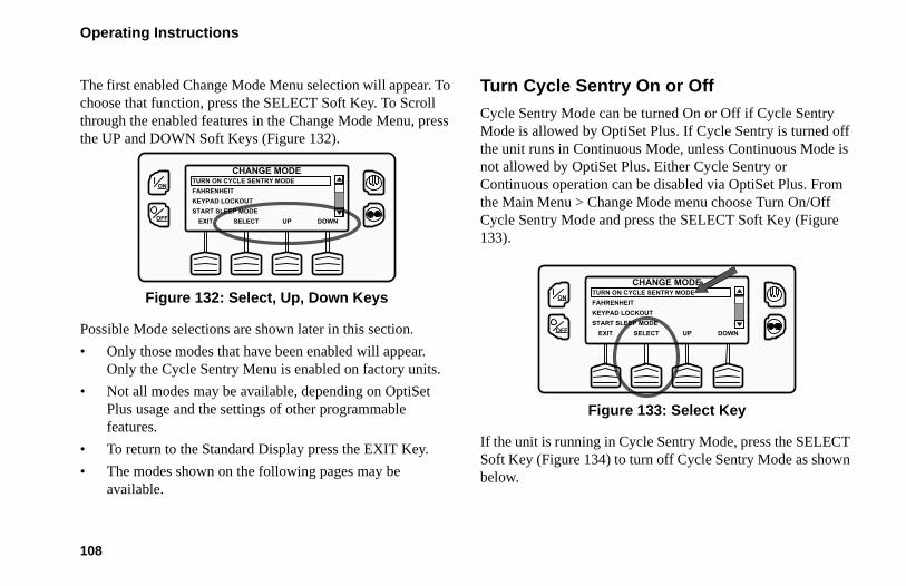
Operating Instructions
108
The first enabled Change Mode Menu selection will appear. To choose that function, press the SELECT Soft Key. To Scroll through the enabled features in the Change Mode Menu, press the UP and DOWN Soft Keys (Figure 132).
Figure 132: Select, Up, Down Keys
Possible Mode selections are shown later in this section.
• Only those modes that have been enabled will appear. Only the Cycle Sentry Menu is enabled on factory units.
• Not all modes may be available, depending on OptiSet Plus usage and the settings of other programmable features.
• To return to the Standard Display press the EXIT Key.
• The modes shown on the following pages may be available.
Turn Cycle Sentry On or OffCycle Sentry Mode can be turned On or Off if Cycle Sentry Mode is allowed by OptiSet Plus. If Cycle Sentry is turned off the unit runs in Continuous Mode, unless Continuous Mode is not allowed by OptiSet Plus. Either Cycle Sentry or Continuous operation can be disabled via OptiSet Plus. From the Main Menu > Change Mode menu choose Turn On/Off Cycle Sentry Mode and press the SELECT Soft Key (Figure 133).
Figure 133: Select Key
If the unit is running in Cycle Sentry Mode, press the SELECT Soft Key (Figure 134) to turn off Cycle Sentry Mode as shown below.
ON
OFF
CHANGE MODE
DOWNEXIT SELECT UP
TURN ON CYCLE SENTRY MODEFAHRENHEITKEYPAD LOCKOUTSTART SLEEP MODE
ON
OFF
CHANGE MODE
DOWNEXIT SELECT UP
TURN ON CYCLE SENTRY MODEFAHRENHEITKEYPAD LOCKOUTSTART SLEEP MODE

Operating Instructions
109
Figure 134: Select Key
Confirmation screens will appear briefly, the unit will switch to Continuous Mode operation and the Cycle Sentry Icon will disappear.
To turn Cycle Sentry back on press the SELECT Key again.
To leave this menu without changing the setting, press the EXIT Soft Key. To return to the Standard Display press the EXIT Soft Key again.
NOTE: Cycle Sentry Mode can also be turned on and off using the Cycle Sentry Key on the HMI Control Panel.
Select Temperature UnitsIf this feature enabled in Guarded Access > Main Menu Configuration, the operator can select temperature units to be displayed as either degrees Fahrenheit or degrees Celsius. From the Main Menu > Change Mode menu choose Fahrenheit or Celsius and press the SELECT Soft Key (Figure 135).
Figure 135: Fahrenheit or Celsius, Select Key
Choose the desired Temperature Units using the UP and DOWN Soft Keys and press the SELECT Soft Key to select the choice (Figure 136).
ON
OFF
CHANGE MODE
EXIT SELECT
TURN OFF CYCLE SENTRY
ON
OFF
CHANGE MODE
DOWNEXIT SELECT UP
TURN ON CYCLE SENTRY MODEFAHRENHEITKEYPAD LOCKOUTSTART SLEEP MODE

Operating Instructions
110
Figure 136: Up, Down, Select Keys
Temperatures will be displayed in the selected units.
• To leave this menu without changing the setting, press the EXIT Soft Key. To return to the Standard Display press the EXIT Soft Key again.
Fresh Air Exchange Open or ClosedIf this option is installed and enabled in Guarded Access > Main Menu Configuration, the Fresh Air Exchange option allows fresh outside air to be drawn into the trailer and the interior air to be exhausted by opening the Fresh Air Exchange door. This feature is beneficial when hauling loads that release gas as they ripen, such as potatoes. The Fresh Air Exchange
feature is only available with setpoints above 32 F (0 C). The feature is disabled with setpoints of 32 F (0 C) and below. This feature may not be available if OptiSet Plus is in use.
The Fresh Air Exchange feature should be used exactly as specified by the customer.
From the Change Mode menu choose Open Fresh Air Exchange and press the SELECT Soft Key (Figure 137).
Figure 137: Select Key
The Fresh Air Exchange door will open. To close the Fresh Air Exchange door press the SELECT Key again.
IMPORTANT: The Fresh Air Exchange feature should be used exactly as specified by the customer.
TEMPERATURE UNITS
EXIT SELECT
FAHRENHEIT
CELSIUS
DOWNUP
ON
OFF
CHANGE MODE
DOWNEXIT SELECT UP
TURN ON CYCLE SENTRY MODEFAHRENHEITOPEN FRESH AIR EXCHANGEKEYPAD LOCKOUT
ON
OFF

Operating Instructions
111
• The Fresh Air Exchange door will only be open when the unit engine is running. The door will close when the engine shuts down to preserve unit battery life.
• The setting of the Fresh Air Exchange door will survive power off/power on cycles - if the door is set to “Open” by the operator it will continue to open any time the engine is running until it is set to “Close” by the operator.
• To leave this menu without changing the setting, press the EXIT Soft Key. To return to the Standard Display press the EXIT Soft Key again.
Keypad LockoutIf enabled in Guarded Access > Main Menu Configuration, the keypad can be locked to prevent unauthorized use. If the keypad is locked, only the On Key and Off Key function. The keypad will remain locked even if the unit is turned off and back on. If Keypad Lockout is active, press and hold any soft key for 5 seconds to deactivate the feature. To turn the feature on, from the Change Mode menu choose Keypad Lockout and press the SELECT Soft Key (Figure 138).
Figure 138: Select Key
A Confirmation Request will appear. To activate Keypad Lockout press the YES Soft Key. To leave this menu without turning the Keypad Lockout feature on, press the NO Soft Key (Figure 139).
Figure 139: NO Soft Key
CHANGE MODE
DOWNEXIT SELECT UP
TURN ON CYCLE SENTRY MODEFAHRENHEITKEYPAD LOCKOUTSTART SLEEP MODE
ON
OFF
ON
OFF
KEYPAD LOCKOUT
ARE YOU SURE?
NOYES

Operating Instructions
112
If the YES Soft Key was pressed Keypad Lockout is active. Repeat the process to turn the Keypad Lockout feature off.
• If the keypad is locked, only the On Key and Off Key function. The keypad will remain locked even if the unit is turned off and back on.
• If Keypad Lockout is active, press and hold any soft key for 5 seconds to deactivate the feature.
• To return to the Standard Display press the EXIT Soft Key again.
Start Sleep ModeIf this feature enabled in Guarded Access > Main Menu Configuration, the operator can select and set Sleep Mode from the Mode Menu. Sleep Mode is used to keep the engine warm and the battery charged when the unit is not in use. When the unit is Sleep Mode the display will show “SLEEP” and the current time. To turn the feature on, from the Change Mode menu choose Start Sleep Mode and press the SELECT Soft Key (Figure 140).
Figure 140: Select Soft Key
The following features are available in Sleep Mode. Follow the display prompts to select and set the features.
• Program Wakeup Time: This feature allows a wakeup time to be specified. When the selected time is reached the unit will start and resume normal operation.
• If a Wakeup Time is selected the following features are available:
• Day to Wake Up: This feature allows the day the unit is to wake up to be specified.
• Hour to Wake Up: This feature allows the hour the unit is to wake up to be specified.
ON
OFF
CHANGE MODE
DOWNEXIT SELECT UP
TURN ON CYCLE SENTRY MODEFAHRENHEITKEYPAD LOCKOUTSTART SLEEP MODE

Operating Instructions
113
• Minute to Wake Up: This feature allows the minute the unit is to wake up to be specified.
• Run Pretrip on Wakeup: This feature allows a Pretrip Test to be automatically run when the unit wakes up.
SmartPower Electric Standby Option The Diesel/Electric Standby selection from the Main Menu allows the operator to manually select diesel or Electric Mode operation on units equipped with the electric standby SmartPower option. The unit can also be programmed to automatically switch to Electric Mode operation when standby power is available and to automatically switch to Diesel Mode operation if standby power fails or is removed. If the unit is programmed to automatically switch from diesel to electric and/or electric to diesel the associated screens do not appear.
• If the unit is currently operating in Diesel Mode the ELECTRIC STANDBY selection will appear in the Main Menu.
• If the unit is currently operating in Electric Mode the Diesel Mode selection will appear in the Main Menu.
Electric Mode OperationIf a unit equipped with the electric standby SmartPower option is running in Diesel Mode, the Diesel to Electric Auto-Switch feature is set NO and the unit is connected to a source of standby power, this feature allows the operator to manually select Electric Mode operation. This feature does not appear if the electric standby SmartPower option is not installed or if the Diesel to Electric Auto-Switch feature is set YES.
Diesel Mode OperationIf a unit equipped with the electric standby SmartPower option is running in Electric Mode, the Electric to Diesel Auto-Switch feature is set NO, this feature allows the operator to manually select Diesel Mode operation. This feature does not appear if the electric standby SmartPower option is not installed or if the Electric to Diesel Auto-Switch feature is set YES.

Operating Instructions
114
Switching from Diesel to ElectricIf the unit is running in Diesel Mode and the Diesel to Electric Auto-Switch Enabled feature in Guarded Access is set YES then the unit will automatically switch to Electric Mode operation when standby power is connected and available. The screens shown below will not appear.
If the unit is running in Diesel Mode and the Diesel to Electric Auto-Switch Enabled feature in Guarded Access is set NO, the unit can be switched to Electric Mode using the Electric Standby selection from the Main Menu.
From the Standard Display, press the MENU Key (Figure 141).
Figure 141: Menu Key
From the Main Menu choose Electric Standby and press the SELECT Soft Key (Figure 142).
Figure 142: Select Key
If the unit has standby power available and is turned on, the electric standby run screen will appear. The new mode is confirmed for 10 seconds. The unit will start and run in Electric Mode. If electric standby power is not available or fails, the display will prompt for a return to Diesel Mode as shown below.
Any engine related Shutdown Alarms become Log Alarms when the unit is switched to Electric Mode operation. If the unit is switched back to Diesel Mode these alarms again become Shutdown Alarms.
MENU35 °F
35SET SENSORSGAUGES
POINT
.8
ON
OFF
ON
OFF
MAIN MENU
DOWNEXIT SELECT UP
HOURMETERSMODEELECTRIC STANDBYADJUST BRIGHTNESS

Operating Instructions
115
Electric Standby Power Fails or is DisconnectedIf the electric standby power source fails or is disconnected and manual switching to Diesel Mode is selected, the unit will prompt for a switch to Diesel Mode (Figure 143).
Figure 143: Diesel Mode Prompt
• Pressing the YES Soft Key will switch unit operation back to Diesel Mode.
• Pressing the NO Soft Key will allow the unit to remain in Electric Mode even though standby power is not available.
The unit will not run and Alarm Code 91 Check Electric Ready Input will be set as a prevent alarm.
Switching from Electric to DieselIf the unit is running in Electric Mode and the Electric to Diesel Auto-Switch Enabled feature in Guarded Access is set YES then the unit will automatically switch to Diesel Mode operation when standby power is no longer available. The screens shown below will not appear.
If the Diesel to Electric Auto-Switch Enabled feature in Guarded Access is set NO and standby power is disconnected or fails, the unit will not automatically switch to Diesel Mode. This is primarily designed to prevent unauthorized diesel engine starts when the truck is indoors or on a ferry where engine operation is strictly prohibited.
From the Standard Display, press the MENU Key (Figure 144).
ON
OFF YES NO
ELECTRIC STANDBY UNDETECTED
DO YOU WISH TO SWITCH TO DIESEL?

Operating Instructions
116
Figure 144: Menu Key
From the Main Menu choose Diesel Mode and press the SELECT Soft Key (Figure 145).
Figure 145: Select Key
The new mode is confirmed for 10 seconds. The unit will start and run in Diesel Mode.
Any electric standby related Shutdown Alarms become Log Alarms when the unit is switched to Diesel Mode operation. If the unit is switched back to Electric Mode these alarms again become Shutdown Alarms.
Adjust BrightnessThe brightness of the HMI Control Panel display can be adjusted to allow for changing ambient light conditions. The choices available to the operator are HIGH, MEDIUM, LOW and OFF. OFF actually results in a very dim screen suitable for low light conditions.
Display brightness is adjusted using the Adjust Brightness Menu. From the Standard Display, press the MENU Key (Figure 146).
MENU35 °F
35SET SENSORSGAUGES
POINT
.8
ON
OFF
ON
OFF
MAIN MENU
DOWNEXIT SELECT UP
HOURMETERSMODEDIESEL MODEADJUST BRIGHTNESS

Operating Instructions
117
Figure 146: Menu Key
The Main Menu will appear. Press the UP or DOWN Key as required to choose the Adjust Brightness Menu. When the Adjust Brightness is selected, press the SELECT Key to choose the Adjust Brightness (Figure 147).
Figure 147: Select Key
The Display Brightness menu will appear as shown below. Press the UP or DOWN Soft Keys to select the desired display brightness. When the desired brightness is shown press the SELECT Soft Key to confirm the choice (Figure 148).
Figure 148: Select Key
To return to the Main Menu press the EXIT Key. To return to the Standard display press the EXIT Key again.
TimeThe Time and Date held by the HMI Control Panel can be checked. Time and Date cannot be changed from the Main Menu. The time and date is accessed using the Main Menu. From the Standard Display, press the MENU Key (Figure 149).
MENU35 °F
35SET SENSORSGAUGES
POINT
.8
ON
OFF
MAIN MENU
DOWNEXIT SELECT UP
MODEELECTRIC STANDBYADJUST BRIGHTNESSTIME
ON
OFF
ON
OFF
DISPLAY BRIGHTNESS WILL BE
DOWNEXIT SELECT UP
OFF
LOW
MEDIUM

Operating Instructions
118
Figure 149: Menu Key
The Main Menu will appear. Press the UP or DOWN Key as required to choose the Time Menu. When the Time Menu is selected, press the SELECT Key to choose the Time Menu (Figure 150).
Figure 150: Select Key
The date and time held in the HMI Control Panel will be shown on the display (Figure 151). Time and Date cannot be changed from the Main Menu.
Figure 151: Date and Time
To return to the Main Menu press the EXIT Key. To return to the Standard display press the EXIT Key again.
Clear All ECU FaultsPressing this key will clear all existing Engine Control Unit (ECU) Fault Codes. This may allow continued unit operation should an ECU fault code result in engine shutdown.
MENU35 °F
35SET SENSORSGAUGES
POINT
.8
ON
OFF
MAIN MENU
DOWNEXIT SELECT UP
ELECTRIC STANDBYADJUST BRIGHTNESSTIMECLEAR ALL ECU FAULTS
ON
OFF
ON
OFF
TIME MENU
01:18 MONDAY 10 DEC 2012
EXIT

Operating Instructions
119
• Any Thermo King Alarm Codes associated with the Engine Control Unit (ECU) Fault Codes will also be cleared.
• The Thermo King Alarm Codes and Engine Control Unit (ECU) Fault Codes that were cleared can be viewed in the ServiceWatch and ECU Data Loggers.
Engine Control Unit (ECU) Fault Codes are cleared using the Clear All ECU Faults Menu. From the Standard Display, press the MENU Key (Figure 152).
Figure 152: Menu key
The Main Menu will appear. Press the UP or DOWN Key as required to choose the Clear All ECU Faults Menu. When the Clear All ECU Faults Menu is selected, press the SELECT Key to choose the Clear All ECU Faults Menu (Figure 153).
Figure 153: Select Key
The Clear All ECU Faults Prompt will appear. To clear all Engine Control Unit (ECU) Faults and associated Thermo King Faults press the CLEAR Soft Key (Figure 154).
MENU35 °F
35SET SENSORSGAUGES
POINT
.8
ON
OFF
MAIN MENU
DOWNEXIT SELECT UP
ADJUST BRIGHTNESSTIMECLEAR ALL ECU FAULTS
ON
OFF

Operating Instructions
120
Figure 154: Clear Key
All Engine Control Unit (ECU) Faults and associated Thermo King Faults will be cleared.
To return to the Main Menu press the EXIT Key. To return to the Standard display press the EXIT Key again.
ON
OFF
CLEAR ALL ECU FAULTS
EXIT CLEAR
CLEAR ALL ECU FAULTS

121
Optional Rear Remote Control PanelThe optional Rear Remote Control Panel is connected to the control system and is used to operate the unit from a remote location, typically at the rear of the trailer. In the illustration below all display segments are turned on.
Figure 155: Rear Remote Control Panel
Rear Remote Control Panel FunctionalityThe Rear Remote Control Panel functions that are available to the user are determined by the setting of the Rear Remote Control Action features in the Guarded Access / Unit Configuration Menu. The Rear Remote Control Action can be set to either RUN or STAND BY.
When the unit is turned on at the Rear Remote Control Panel either the Standard Display or [STAnd by] will appear on the display.
Rear Remote Control Action Set to RunIf the Rear Remote Control Action is set to RUN the Standard Display will be present on the Rear Remote Control Panel and the unit will start and run when the Rear Remote Control Panel ON Key is pressed. Pressing the Rear Remote Control Panel OFF Key will turn the unit off.

Optional Rear Remote Control Panel
122
If the control system is powered up from the Rear Remote Control Panel the Standard Display will appear in both the Rear Remote Control Panel display and the unit Control Panel display. When set to RUN the Rear Remote Control Panel allows the following:
• Turn the unit on and off
• Unit will start and run
• Change the Setpoint
• Select Cycle-Sentry or Continuous Mode
• Display discharge air temperature
• Display and clear alarm codes
• Initiate a manual defrost cycle
• Send a Start of Trip marker to the ServiceWatch and CargoWatch Data Loggers
• Initiate a Pretrip Test
Rear Remote Control Action Set to STAND BYIf the Rear Remote Control Action is set to STAND BY, pressing the Rear Remote Control Panel ON Key will power up the control system, but the unit will not start and run. Pressing the Rear Remote Control Panel OFF Key will turn the unit off. The Control Panel on the unit must be used to start and stop unit operation.
In addition to turning the unit on and off, when set to STAND BY the Rear Remote Control Panel allows the following:
• Turn the unit on and off
• Unit will not start and run
• Change the Setpoint
• Select Cycle Sentry or Continuous Mode (unless prevented by OptiSet Plus)
• Display discharge air temperature
• Display and clear alarm codes
• Send a Start of Trip marker to the ServiceWatch and CargoWatch Data Loggers

Optional Rear Remote Control Panel
123
When in STAND BY, the unit will not start and run and a defrost cycle or Pretrip Test cannot be started.
If the control system is powered up from the remote control panel a stand by message will appear in both the remote control panel display and the unit Control Panel display as shown in Figure 156 and Figure 157.
Figure 156: Rear Remote Control Panel Display
Figure 157: Unit Control Panel Display
When the StAnd bY display is shown, press the Select Key to show the Remote Standard Display. When the remote standard Display is shown, the setpoint and operating mode can be changed, the discharge air temperature can be displayed and alarms can be viewed and cleared. In addition, a Start of Trip can be sent to the data loggers.
After the last key is pressed, the display will return to the StAnd bY display shown in Figure 158 in about 10 seconds.
Figure 158: Press Select Key

Optional Rear Remote Control Panel
124
KeypadThe nine touch sensitive keys are used to turn the unit on and off. They also allow the setpoint to be changed, Cycle Sentry or Continuous Mode to be selected, Alarm Codes and other operating data to be displayed and Pretrip Tests and Defrost Cycles to be performed. A Start of Trip marker can also be sent to the data loggers.
Figure 159: Rear Remote Control Panel
ON KeyTurns the unit on as determined by the setting of Rear Remote Control Action.
OFF Key Turns the unit off.
Up Arrow Key
Increases setpoint or changes other setting.
Down Arrow Key
Decreases setpoint or changes other setting.
Select KeyAllows Cycle-Sentry to be turned on and off, displays the discharge air temperature and alarms.
Enter KeyExecutes a prompt or loads a new setpoint or other setting.
Pretrip Key Initiates a Pretrip Test.

Optional Rear Remote Control Panel
125
DisplayThe display normally shows the Standard Display of return air temperature and setpoint. The icons on either side of the display indicate operating modes and alarms. The display shown here has all possible segments lighted. The display icons are defined below.
Figure 160: Rear Remote Control Panel
TK Logo Key
Sends a Start of Trip marker to the data logger.
Defrost KeyInitiates a defrost cycle if conditions allow.
Cool IconThis icon appears when the unit is cooling.
Heat IconThis icon appears when the unit is heating.
Modulation Icon
This icon appears when the unit is in modulation.
Defrost IconThis icon appears when the unit is defrosting.
Cycle-Sentry Icon
This icon appears when the unit is operating in Cycle-Sentry mode.
Alarm IconThis icon appears when an alarm condition has been detected.
Electric Standby Icon
This icon appears when the unit is operating in the optional electric standby mode.
Setpoint Icon
This icon appears when the setpoint is being shown in the display.
Not UsedThis icon appears during a remote control panel test but is not currently used.

Optional Rear Remote Control Panel
126
Reading a Typical Remote Standard DisplayThe Remote Standard Display shows the temperature and setpoint. The icons at the sides of the display indicate operating conditions.
Figure 161: Remote Standard Display
The Remote Standard Display in Figure 161 shows the following information:
• The temperature (typically return air temperature) is 35.8°F.
• The setpoint is 35°F.
• The unit is cooling as shown by the icon at the upper left side of the display.
• The unit is operating in Cycle Sentry mode as shown by the icon at the upper right side of the display.
Remote Control Panel LockoutThe remote control panel may be locked out during some control system functions such as Service Test Mode, Interface Board Test Mode and while setting programmable features. If this is the case the display shown in Figure 162 will appear. The display will return to the Remote Standard Display when allowed by the control system.
Figure 162: Remote Lock Out Display

Optional Rear Remote Control Panel
127
Turning the Unit ON or OFF (Configured for STAND BY Operation)The control system is turned on by pressing the ON Key and off by pressing the OFF Key. When the On Key is pressed the remote display briefly shows all segments and then StAnd by as shown in Figure 163. A stand by message will also appear on the unit Control Panel display. The setpoint can be changed but the unit will not start and run. Only the Select Key, Enter Key and Up and Down Arrow Keys are functional. The unit can be started and run by pressing the unit Control Panel ON Key.
IMPORTANT: To change the setpoint, press the Select Key to show the Remote Standard Display. The setpoint can now be changed as shown on page 128.
Figure 163: Stand By Display
Turning the Unit On and Off (Configured for RUN Operation)The unit is turned on by pressing the ON key and off by pressing the OFF key. When the ON key is pressed the remote display briefly shows all segments and then COn FIg as the control system initializes. Then the Remote Standard Display will appear as shown in Figure 164. The unit will start and run if necessary.

Optional Rear Remote Control Panel
128
Figure 164: Standard Display
Changing the SetpointThe setpoint can be changed when the Remote Standard Display is shown.
1. When the Remote Standard Display is shown, press the Up or Down Arrow Keys to select the desired setpoint (Figure 165).
Figure 165: Press Up or Down Arrow Keys

Optional Rear Remote Control Panel
129
2. When the desired setpoint is shown on the display, immediately press the Enter Key to load the new setpoint. The display will briefly show [Lod] and then the new setpoint will reappear in the display.
IMPORTANT: The Enter key (Figure 166) must be pressed or the setpoint will not be changed. The display will return to the Standard Display and the setpoint will return to the old setpoint in about 10 seconds if the Enter Key is not pressed. Alarm Code 127 Setpoint Not Entered is set, to indicate that the setpoint change was started but not completed.
Figure 166: Press Enter Key
IMPORTANT: Confirm that the correct setpoint is set.
Selecting Cycle-Sentry or Continuous ModeCycle Sentry or Continuous Mode operation can be changed using the Select Key.
1. When the Remote Standard Display is shown, press the Select key once to display the Cycle Sentry prompt.
Figure 167: Press Select Key
2. Use the Up and Down Arrow Keys to chose either YES or nO. Yes = Cycle Sentry Mode. nO = Continuous Mode.

Optional Rear Remote Control Panel
130
Figure 168: Press Up or Down Arrow Keys
3. When the desired selection is shown, press the Enter Key (Figure 169) to load the setting. The display will briefly show [Lod] and then the new selection will briefly appear in the display.
Figure 169: Press Enter Key
4. The display will then return to the Remote Standard Display.
Displaying the Discharge Air TemperatureThe discharge air temperature can be shown using the Select Key.
1. When the Remote Standard Display is shown, press the Select Key twice. The discharge air temperature will be shown in the display for about 10 seconds.
Figure 170: Press Select Key Twice
2. The display will then return to the Remote Standard Display.
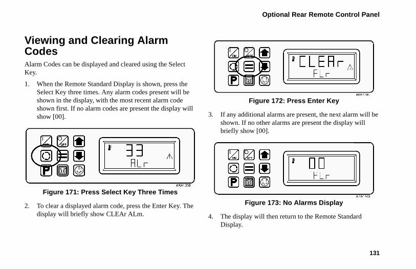
Optional Rear Remote Control Panel
131
Viewing and Clearing Alarm CodesAlarm Codes can be displayed and cleared using the Select Key.
1. When the Remote Standard Display is shown, press the Select Key three times. Any alarm codes present will be shown in the display, with the most recent alarm code shown first. If no alarm codes are present the display will show [00].
Figure 171: Press Select Key Three Times
2. To clear a displayed alarm code, press the Enter Key. The display will briefly show CLEAr ALm.
Figure 172: Press Enter Key
3. If any additional alarms are present, the next alarm will be shown. If no other alarms are present the display will briefly show [00].
Figure 173: No Alarms Display
4. The display will then return to the Remote Standard Display.
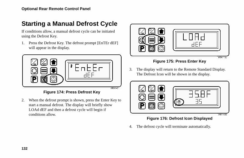
Optional Rear Remote Control Panel
132
Starting a Manual Defrost CycleIf conditions allow, a manual defrost cycle can be initiated using the Defrost Key.
1. Press the Defrost Key. The defrost prompt [EnTEr dEF] will appear in the display.
Figure 174: Press Defrost Key
2. When the defrost prompt is shown, press the Enter Key to start a manual defrost. The display will briefly show LOAd dEF and then a defrost cycle will begin if conditions allow.
Figure 175: Press Enter Key
3. The display will return to the Remote Standard Display. The Defrost Icon will be shown in the display.
Figure 176: Defrost Icon Displayed
4. The defrost cycle will terminate automatically.

Optional Rear Remote Control Panel
133
Sending a Start of Trip MarkerA Start of Trip marker can be sent to the data loggers using the TK Logo Key.
1. Press the TK Logo Key. The Start of Trip [EnTEr SOt] prompt will appear in the display.
Figure 177: Press TK Logo Key
2. When the Start of Trip prompt is shown, press the Enter Key to send a Start of Trip marker to the CargoWatch and ServiceWatch data loggers. The display will briefly show LOAd SOt.
Figure 178: Press Enter Key
3. The display will then return to the Remote Standard Display.

Optional Rear Remote Control Panel
134
Running a Pretrip TestA Pretrip Test can be started using the Pretrip Key as long as the unit is not in STAND BY. If the unit is not running when the Pretrip Test is started a Full Pretrip Test will be performed. If the unit is running when the Pretrip Test is started a Running Pretrip Test will be performed.
1. Clear any alarm codes as shown previously.
2. Press the Pretrip Key. The Pretrip [EntEr PrE] prompt will appear in the display.
Figure 179: Press Pretrip Key
3. When the Pretrip prompt is shown, press the Enter Key to start a Pretrip Test. The display will briefly show LOAd PrE. If the unit is not running a Full Pretrip Test will be performed. If the unit is running a Running Pretrip Test will be performed.
Figure 180: Press Enter Key

Optional Rear Remote Control Panel
135
4. When the Pretrip Test is running the display will show PrE trP. The Control Panel will show the Pretrip Test progress.
Figure 181: Pretrip Display
5. When the Pretrip Test is complete the display will show PASS, CHEC or FAIL. Pressing the Select Key will return to the Remote Standard Display.
Figure 182: Pass Pretrip Display

136
Loading and Enroute InspectionsThis chapter describes pre-loading, post loading, and enroute inspection procedures. Thermo King refrigeration units are designed to maintain the required product load temperature during transit. Follow these recommended loading and enroute procedures to help minimize temperature related problems.
Pre-Loading Inspection1. Pre-cool products before loading. Note any variances on
the manifest.
2. Inspect door seals and vent doors for condition and a tight seal with no air leakage.
3. Inspect the trailer inside and out. Look for:
• Damaged or loose trailer skin and insulation
• Damaged walls, air ducts, floor channels or “T” flooring
• Clogged defrost drain tubes
• Blocked return air bulkhead
4. Verify that the setpoint temperature is correct for your cargo. Pre-cool the trailer as required.
5. Supervise product loading to ensure sufficient air space around and through the load. Airflow around the cargo must not be restricted.
NOTE: If the warehouse is not refrigerated, operate the unit with doors closed until cargo is ready to be loaded. Then turn off the unit, open cargo doors and load cargo. When cargo is loaded, close trailer doors and restart the unit.The unit can be operated with the cargo box doors open if the truck is backed into a refrigerated warehouse and the dock door seals fit tightly around the trailer.

Loading and Enroute Inspections
137
Figure 183: Loading Considerations
ADZ30
6
8
9
1
2
5
47
1. Correct load height (trailers without chutes)2. Tight doors and gaskets3. Good air circulation around load4. Proper cargo temperature (prior to loading)5. Interior/exterior walls and insulation in good
condition6. Clear defrost drains7. Good outside air circulation8. Unit inspection9. Tight seals
3

Loading and Enroute Inspections
138
Post-Loading InspectionPost-loading inspections ensure the cargo has been loaded properly. To perform a post-load inspection:
1. Inspect the evaporator outlets for blockage.
2. Turn the unit off before opening the cargo box doors to maintain efficient operation.
NOTE: The unit can be operated with the cargo box doors open if the truck is backed into a refrigerated warehouse and the dock door seals fit tightly around the trailer.
3. Perform a final check of the load temperature. If the load is above or below temperature, make a final notation on the manifest.
4. Close or supervise the closing of the cargo box doors. Make sure they are securely locked.
5. Make sure the setpoint is at the temperature listed on the manifest.
6. If the unit was stopped, restart using the correct starting procedure. See the Operating Instruction chapter in this manual.
7. Start a manual defrost cycle 30 minutes after loading. See the Manual Defrost procedure in this manual.
CAUTION: Cargo must be pre-cooled to the proper temperature before loading. The unit is designed to maintain temperature, not cool an above-temperature load.

Loading and Enroute Inspections
139
Enroute InspectionsComplete the following enroute inspection every four hours. This will help minimize temperature related problems.
Inspection Procedure1. Verify setpoint is correct.
2. Check the return air temperature reading. It should be within the desired temperature range.
3. Initiate a manual defrost cycle after each enroute inspection.
Inspection Troubleshooting1. If a temperature reading is not within the desired
temperature range, refer to the troubleshooting table on the following pages. Correct problem as required.
2. Repeat the Enroute Inspection every 30 minutes until the compartment temperature is within the desired temperature range. Stop the unit if the compartment temperature is not within the desired temperature range on two consecutive 30 minute inspections, especially if the compartment temperature appears to be moving away from the setpoint.
3. Immediately contact the nearest Thermo King Service Center or your company office.
4. Take all necessary steps to protect and maintain proper load temperature.
CAUTION: Stop the unit if the compartment temperature remains higher than the desired temperature range from the setpoint on two consecutive 30 minute inspections. Contact the nearest Thermo King Service Center or your company office immediately. Take all necessary steps to protect and maintain proper load temperature.

Loading and Enroute Inspections
140
Inspection Troubleshooting
Problem Cause Remedy
A return air temperature reading is not within desired temperature range of the setpoint.
The unit has not had time to cool down to correct temperature.
Refer to the load log history. Look for above temperature load records, properly pre-cooled cargo compartment, length of time on road, etc. Correct as required. Continue monitoring return air temperature until the reading is within the desired temperature range of the setpoint.
The unit may have a low refrigerant charge.
Check the receiver tank sight glass for refrigerant level. If liquid is not showing in the receiver tank sight glass, the refrigerant charge may be low. A competent refrigeration technician is required to add refrigerant or repair the system. Contact the nearest Thermo King dealer, authorized Service Center, or call the Thermo King Cold Line for referral. Consult the Table of Contents for Cold Line information.
The unit is in defrost or has just completed a defrost cycle.
Monitor the return air temperature after the defrost cycle is completed to see if the temperature returns to the desired temperature range of the setpoint.
The evaporator is plugged with frost.
Initiate a manual defrost cycle. The defrost cycle will automatically terminate when complete. Continue monitoring the return air temperature until the reading is within the desired temperature range of the setpoint.

Loading and Enroute Inspections
141
Improper air circulation in the cargo compartment.
Inspect the unit and cargo compartment to determine if the evaporator fan(s) are working and properly circulating the air. Poor air circulation may be due to improper loading of the cargo, shifting of the load, or fan belt slippage. Correct as required. Continue monitoring return air temperature until problem is corrected.
The unit did not start automatically.
Determine the cause for not starting. Correct as required. Continue monitoring the return air temperature until the reading is within the desired temperature range of the setpoint.
Problem Cause Remedy

142
Alarm Codes
IntroductionAn alarm code is generated when the microprocessor senses an abnormal condition. Alarms direct an operator or service technician to the source of a problem.
Multiple alarms can be present at one time. All generated alarms will be stored in memory until cleared by the operator. Document all alarm occurrences and report them to the service technician.
See “Alarms Menu” in the Operation Instructions Chapter for information about viewing and clearing alarms.
NOTE: Some alarms (3, 4, 74, 203, and 204) cannot be cleared in the Alarms Menu, they must be cleared in the Maintenance Menu or the Guarded Access Menu. Contact your supervisor or a Thermo King dealer about clearing those alarms.
IMPORTANT: Always record any Alarm Codes that occur - in the order that they occur - as well as any other pertinent information. This information is extremely valuable to service personnel.
NOTE: In some cases alarms cannot be cleared, or cannot be cleared after they have occurred a specified number of times. If such is the case, these alarms must be cleared by service personnel. See “Clearing Alarm Codes” on page 145.
Alarm TypesThe four types of alarms are described below.
Log Alarms: Log Alarms are indicated by the Log Alarms screen, which appears for approximately 30 seconds (just before the Standard Display appears) each time the unit is turned on. The Alarm Display must be used to view the existing alarms. This level of alarm serves as a notice to take

Alarm Codes
143
corrective action before a problem becomes severe. Maintenance items such as a maintenance reminder hour meter reaching its time limit are log alarms.
Figure 184: Log Alarms Screen
Check Alarms: Check Alarms are indicated by the Alarm Display in which the large Alarm Icon will appears on the Standard Display as shown below in Figure 185. The Alarm Menu must be used to view the existing alarms. This level of alarm serves as a notice to take corrective action before a problem becomes severe. The unit will run with check alarms but some features and functions may be inhibited.
Figure 185: Alarm Display
Prevent Alarms: Prevent Alarms are also indicated by the Alarm Display as shown in Figure 185. The Alarm Menu must be used to view the existing alarms. The unit may stop running and wait a timed interval or until conditions allow and then restart. If the unit is waiting to restart, Alarm Code 84 Restart Null will be present along with the Prevent Alarm. In other cases the unit may restart or run with reduced performance to determine if continued operation is possible. If the alarm does not reoccur with reduced performance the unit will then return to full performance. If the unit is operating with reduced performance Alarm Code 85 Forced Unit Operation will also be present.
ON
OFF
LOG ALARMS ACTIVE
GO TO MENU TO VIEW
EXIT
MENU35 35
SET SENSORSGAUGESPOINT
ON
OFF

Alarm Codes
144
Shutdown Alarms: Shutdown Alarms are indicated by the Alarm Display. Shutdown alarms also cause the display and backlight to flash on and off, and the display will switch from normal video to reverse video and back to normal video (light areas become dark and dark areas become light as shown in Figure 186). Shutdown alarms force the unit into shutdown. The unit will remain in shutdown and will not restart until the shutdown alarm is cleared. Exceptions are some engine and electric shutdown alarms become that log alarms when switched to the alternate operating mode (diesel to electric or electric to diesel).
If a shutdown alarm occurs that affects only Diesel Mode operation and the unit is switched to electric (either manually or automatically), the Diesel Mode shutdown alarm becomes an Electric Mode log alarm. This allows the unit to run in Electric Mode without clearing the shutdown alarm that is preventing Diesel Mode operation. If the unit is switched back to Diesel Mode, the alarm again becomes a Diesel Mode shutdown alarm and prevents unit operation. If the unit is configured for electric to diesel autoswitch, it automatically starts and runs in Diesel Mode if an electric shutdown occurs.
In the same manner, if a shutdown alarm occurs that affects only Electric Mode operation and the unit is switched to diesel (either manually or automatically), the Electric Mode shutdown alarm becomes a Diesel Mode log alarm to allow Diesel Mode operation. If the unit is switched back to Electric Mode, the alarm reverts to an Electric Mode shutdown alarm and prevents unit operation.
Figure 186: Shutdown Alarm Display
Pretrip Alarm CodesIf an alarm occurs during a Pretrip Test the alarm code will be displayed as Pretrip Alarm XX, where XX is the alarm code.
MENU35 35
SET SENSORSGAUGESPOINT
ON
OFF

Alarm Codes
145
Clearing Alarm CodesMost alarm codes can be cleared conventionally from the Alarm Menu using the CLEAR Key. See the Operating Instructions chapter for procedures.
The operator should contact a supervisor or a Thermo King dealer about clearing alarms using the Guarded Access Menu.
Refer to the table on the following pages for alarm corrective action.
NOTE: Document all alarm faults and report them to the service technician.
There are three levels of corrective action that can be taken when an alarm condition occurs.
OK To Run: An alarm condition exists but does not affect unit operation. Corrective action can occur at a later date.
Check As Specified: An alarm condition exists that could affect unit operation. Follow directions in the Corrective Action column on the following chart.
Take Immediate Action: An alarm condition exists that will damage the unit or load. Take immediate action to correct the problem.
NOTE: The corrective actions listed in the Operating Instructions chapter and in the chart on the following pages are suggestions only. Always consult your company for final decisions.
NOTE: The chart on the following pages shows all possible alarm codes for all possible applications. Not all codes will be applicable to each individual unit.

Alarm Codes
146
Table of Alarm CodesNOTE: Not all alarm codes are available with all microprocessor controllers or all revisions of software.
Code Description Corrective Action Level Of Action
Ok
To
Ru
n
Ch
eck
Sh
ut
D
ow
n
00 No Alarms Exist None required X
2 Evaporator Coil SensorManually monitor load temperature with independent thermometer. Report alarm at end of day.
X
3 Control Return Air SensorManually monitor load temperature with independent thermometer. Report alarm at end of day.
X
4 Control Discharge Air SensorManually monitor load temperature with independent thermometer. Report alarm at end of day.
X
5 Ambient Air Sensor Report alarm at end of day. X
6 Coolant Temp Sensor Report alarm at end of day. X
7 Engine RPM Sensor Report alarm at end of day. X
9 High Evaporator TemperatureManually monitor load temperature. Report alarm at end of the day.
X

Alarm Codes
147
10 High Discharge PressureIf unit is shut down repair immediately. Otherwise, report alarm at end of day.
X
11Unit Controlling on Alternate Sensor
Manually monitor load temperature with independent thermometer. Report alarm at end of day.
X
12 Sensor or Digital Input ShutdownThe indicated zone is no longer able to operate and has been shut down. Repair immediately.
X
13 Sensor Calibration CheckManually monitor load temperature with independent thermometer. Report alarm at end of day.
X
17 Engine Failed to CrankIf unit is shut down repair immediately. Otherwise, report alarm at end of day.
X
18High Engine Coolant Temperature
If unit is shutdown repair immediately. Otherwise, report alarm at end of day.
X
19 Low Engine Oil PressureIt unit is shutdown repair immediately. Otherwise report alarm at end of day.
X
Table of Alarm CodesNOTE: Not all alarm codes are available with all microprocessor controllers or all revisions of software.
Code Description Corrective Action Level Of Action
Ok
To
Ru
n
Ch
eck
Sh
ut
D
ow
n

Alarm Codes
148
20 Engine Failed to StartIf unit is shutdown repair immediately. Otherwise, report alarm at end of day.
X
21 Cooling Cycle CheckManually monitor load temperature with independent thermometer. Report alarm at end of day.
X
22 Heating Cycle CheckManually monitor load temperature with independent thermometer. Report alarm at end of day.
X
23 Cooling Cycle FaultThe indicated zone is no longer able to operate and has been shut down. Repair immediately.
X
24 Heating Cycle FaultThe indicated zone is no longer able to operate and has been shut down. Repair immediately.
X
25 Alternator CheckIf unit is shutdown repair immediately. Otherwise, report alarm at end of day.
X
26 Refrigeration Capacity Manually monitor load temperature with independent thermometer. Report alarm at end of day.
X
Table of Alarm CodesNOTE: Not all alarm codes are available with all microprocessor controllers or all revisions of software.
Code Description Corrective Action Level Of Action
Ok
To
Ru
n
Ch
eck
Sh
ut
D
ow
n

Alarm Codes
149
28 Pretrip Abort Report alarm at end of day. X
29 Defrost Damper Circuit If unit is shutdown, repair immediately. Otherwise, report alarm at end of day.
X
30 Defrost Damper StuckIf unit is shutdown, repair immediately. Otherwise, report alarm at end of day.
X
31 Oil Pressure SwitchIf unit is shutdown repair immediately. Otherwise, report alarm at end of day.
X
32 Refrigeration Capacity LowThe indicated zone is no longer able to operate and has been shut down. Repair immediately.
X
33 Check Engine RPM Report alarm at end of day. X
35 Run Relay CircuitIf unit is shutdown, repair immediately. Otherwise, report alarm at end of day.
X
Table of Alarm CodesNOTE: Not all alarm codes are available with all microprocessor controllers or all revisions of software.
Code Description Corrective Action Level Of Action
Ok
To
Ru
n
Ch
eck
Sh
ut
D
ow
n

Alarm Codes
150
36 Electric Motor Failed to RunIf unit is shutdown, repair immediately. Otherwise, report alarm at end of day.
X
37 Engine Coolant LevelCheck coolant level, add as needed. Report alarm at end of day.
X
38 Electric Phase Reversed If unit is shutdown, repair immediately. Otherwise, report alarm at end of day.
X
39 Water Valve CircuitIf unit is shutdown, repair immediately. Otherwise, report alarm at end of day.
X
40 High Speed CircuitIf unit is shutdown, repair immediately. Otherwise, report alarm at end of day.
X
41Check Engine Coolant Temperature
If unit is shutdown, repair immediately. Otherwise, report alarm at end of day.
X
42 Unit Forced to Low Speed Report alarm at end of day. X
Table of Alarm CodesNOTE: Not all alarm codes are available with all microprocessor controllers or all revisions of software.
Code Description Corrective Action Level Of Action
Ok
To
Ru
n
Ch
eck
Sh
ut
D
ow
n

Alarm Codes
151
43Unit Forced to Low Speed Modulation
Report alarm at end of day. X
44 Check Fuel System Refill fuel tank. X
45Hot Gas Bypass or Hot Gas Bypass Circuit
If unit is shutdown repair immediately. Otherwise, report alarm at end of day.
X
46 Check Air FlowIf unit is shut down repair immediately. Otherwise, report alarm at end of the day. Cargo may be restricting air flow, check load.
X
48 Check Belts/ClutchIf unit is shutdown, repair immediately. Otherwise, report alarm at end of day.
X
50 Reset Clock Report alarm at end of day. X
52 Heat CircuitIf unit is shutdown, repair immediately. Otherwise, report alarm at end of day.
X
Table of Alarm CodesNOTE: Not all alarm codes are available with all microprocessor controllers or all revisions of software.
Code Description Corrective Action Level Of Action
Ok
To
Ru
n
Ch
eck
Sh
ut
D
ow
n
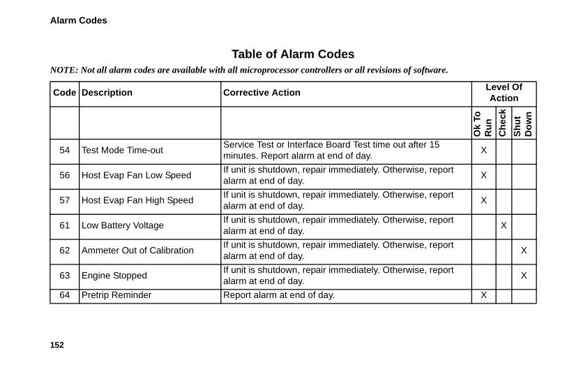
Alarm Codes
152
54 Test Mode Time-outService Test or Interface Board Test time out after 15 minutes. Report alarm at end of day.
X
56 Host Evap Fan Low SpeedIf unit is shutdown, repair immediately. Otherwise, report alarm at end of day.
X
57 Host Evap Fan High SpeedIf unit is shutdown, repair immediately. Otherwise, report alarm at end of day.
X
61 Low Battery VoltageIf unit is shutdown, repair immediately. Otherwise, report alarm at end of day.
X
62 Ammeter Out of CalibrationIf unit is shutdown, repair immediately. Otherwise, report alarm at end of day.
X
63 Engine StoppedIf unit is shutdown, repair immediately. Otherwise, report alarm at end of day.
X
64 Pretrip Reminder Report alarm at end of day. X
Table of Alarm CodesNOTE: Not all alarm codes are available with all microprocessor controllers or all revisions of software.
Code Description Corrective Action Level Of Action
Ok
To
Ru
n
Ch
eck
Sh
ut
D
ow
n

Alarm Codes
153
65Abnormal Temperature Differential
If unit is shutdown, repair immediately. Otherwise, report alarm at end of day
X
66 Low Engine Oil LevelCheck engine oil level. If unit is shutdown, repair immediately. Otherwise, report alarm at end of day.
X
67 Liquid Line Solenoid CircuitIf unit is shutdown, repair immediately. Otherwise, report alarm at end of day.
X
68 Internal Controller Fault Report alarm at end of day. X
70 Hourmeter Failure Report alarm at end of day. X
74 Controller Reset to Defaults Report alarm at end of day. X
79 Internal Data Logger Overflow Report alarm at end of day. X
80 Compressor Temp Sensor Report alarm at end of day. X
82High Compressor Temperature Shutdown
If unit is shutdown repair immediately. Otherwise, report alarm at end of day.
X
Table of Alarm CodesNOTE: Not all alarm codes are available with all microprocessor controllers or all revisions of software.
Code Description Corrective Action Level Of Action
Ok
To
Ru
n
Ch
eck
Sh
ut
D
ow
n

Alarm Codes
154
83 Low Engine Coolant TemperatureIf unit is shutdown repair immediately. Otherwise, report alarm at end of day.
X
84 Restart Null Report alarm at end of day. X
85 Forced Unit Operation Report alarm at end of day. X
86 Discharge Pressure Sensor Report alarm at end of day. X
87 Suction Pressure Sensor Report alarm at end of day. X
89Check Electronic Throttling Valve Circuit
If unit is shutdown repair immediately. Otherwise, report alarm at end of day.
X
90 Electric OverloadIf unit is shutdown, repair immediately. Otherwise, report alarm at end of day.
X
91 Electric Ready InputIf unit is shutdown, repair immediately. Otherwise, report alarm at end of day.
X
92 Sensor Grades Not Set Report alarm at end of day. X
Table of Alarm CodesNOTE: Not all alarm codes are available with all microprocessor controllers or all revisions of software.
Code Description Corrective Action Level Of Action
Ok
To
Ru
n
Ch
eck
Sh
ut
D
ow
n

Alarm Codes
155
93Low Compressor Suction Pressure
If unit is shutdown, repair immediately. Otherwise, report alarm at end of day.
X
96 Low Fuel LevelCheck engine fuel level and add fuel. If unit is shutdown, repair immediately. Otherwise, report alarm at end of day.
X
98 Fuel Level Sensor Report alarm at end of day. X
99 High Compressor Pressure RatioIf unit is shutdown, repair immediately. Otherwise, report alarm at end of day.
X
105Receiver Tank Pressure Solenoid Circuit
If unit is shutdown, repair immediately. Otherwise, report alarm at end of day.
X
106 Purge Valve CircuitIf unit is shutdown, repair immediately. Otherwise, report alarm at end of day.
X
107 Condenser Inlet Solenoid CircuitIf unit is shutdown, repair immediately. Otherwise, report alarm at end of day.
X
Table of Alarm CodesNOTE: Not all alarm codes are available with all microprocessor controllers or all revisions of software.
Code Description Corrective Action Level Of Action
Ok
To
Ru
n
Ch
eck
Sh
ut
D
ow
n

Alarm Codes
156
108 Door Open Time-out Close Doors. Report alarm at end of day. X
110 Suction Line Solenoid CircuitIf unit is shutdown, repair immediately. Otherwise, report alarm at end of day.
X
111 Unit Not Configured Correctly Report alarm at end of day. X
112 Remote FansIf unit is shutdown, repair immediately. Otherwise, report alarm at end of day.
X
113 Electric Heat CircuitIf unit is shutdown, repair immediately. Otherwise, report alarm at end of day.
X
114 Multiple Alarms - Cannot RunIf unit is shutdown repair immediately. Otherwise, report alarm at end of day.
X
117Auto switch from Diesel to Electric
Report alarm at end of day. X
Table of Alarm CodesNOTE: Not all alarm codes are available with all microprocessor controllers or all revisions of software.
Code Description Corrective Action Level Of Action
Ok
To
Ru
n
Ch
eck
Sh
ut
D
ow
n

Alarm Codes
157
118Auto switch from Electric to Diesel
Report alarm at end of day. X
120 Alternator Exciter CircuitIf unit is shutdown, repair immediately. Otherwise, report alarm at end of day.
X
121 Liquid Injection CircuitIf unit is shutdown, repair immediately. Otherwise report alarm at end of day.
X
122 Diesel/Electric Relay CircuitIf unit is shutdown, repair immediately. Otherwise, report at end of day.
X
127 Setpoint Not Entered Be sure the setpoint is set to the required temperature. X
128Engine Run Time Maintenance Reminder #1
Report alarm at end of day. X
129Engine Run Time Maintenance Reminder #2
Report alarm at end of day. X
Table of Alarm CodesNOTE: Not all alarm codes are available with all microprocessor controllers or all revisions of software.
Code Description Corrective Action Level Of Action
Ok
To
Ru
n
Ch
eck
Sh
ut
D
ow
n

Alarm Codes
158
130Electric Run Time Maintenance Reminder #1
Report alarm at end of day. X
131Electric Run Time Maintenance Reminder #2
Report alarm at end of day. X
132Total Unit Run Time Maintenance Reminder #1
Report alarm at end of day. X
133Total Unit Run Time Maintenance Reminder #2
Report alarm at end of day. X
134 Controller Power On Hours Report alarm at end of day. X
141Autoswitch Diesel to Electric Disabled
Report alarm at end of the day. X
143Remote Zone Drain Hose Heater Output
If unit is shutdown, repair immediately. Otherwise, report at end of day.
X
Table of Alarm CodesNOTE: Not all alarm codes are available with all microprocessor controllers or all revisions of software.
Code Description Corrective Action Level Of Action
Ok
To
Ru
n
Ch
eck
Sh
ut
D
ow
n

Alarm Codes
159
144Lost Expansion Module CAN Communication
If unit is shut down repair immediately. Otherwise, report alarm at end of the day.
X
145Loss of Controller “On” Feedback Signal
If unit is shut down repair immediately. Otherwise, report alarm at end of the day.
X
146 Software Version MismatchIf unit is shut down repair immediately. Otherwise, report alarm at end of the day.
X
148Autoswitch Electric to Diesel Disabled
Report alarm at end of the day. X
150 Out of Range LowManually monitor load temperature. Report alarm at end of the day.
X
151 Out of Range HighManually monitor load temperature. Report alarm at end of the day.
X
153Expansion Module Flash Load Failure
If unit is shut down repair immediately. Otherwise, report alarm at end of the day.
X
Table of Alarm CodesNOTE: Not all alarm codes are available with all microprocessor controllers or all revisions of software.
Code Description Corrective Action Level Of Action
Ok
To
Ru
n
Ch
eck
Sh
ut
D
ow
n

Alarm Codes
160
157 OptiSet Plus MismatchManually monitor load temperature. Report alarm at the end of the day
X
158 Primary Software Failed to Load Report alarm at end of the day. X
159 Check Battery ConditionIf unit is shut down repair immediately. Otherwise, report alarm at end of the day.
X
160Lost Radio Expansion Board (REB) CAN Communication
If unit is shut down repair immediately. Otherwise, report alarm at end of the day.
X
203 Display Return Air SensorManually monitor load temperature with independent thermometer. Report alarm at end of day.
X
204 Display Discharge Air SensorManually monitor load temperature with independent thermometer. Report alarm at end of day.
X
230 Future REB Alarm
231 Future REB Alarm
Table of Alarm CodesNOTE: Not all alarm codes are available with all microprocessor controllers or all revisions of software.
Code Description Corrective Action Level Of Action
Ok
To
Ru
n
Ch
eck
Sh
ut
D
ow
n

Alarm Codes
161
232 Future REB Alarm
233REB Transitioning From Conservative to Full Null
Report alarm at end of the day. X
234 Relative Humidity Sensor Report alarm at end of the day. X
251 REB Miss-configured Report alarm at end of the day. X
252Check Fresh Air Exchange Circuit
If unit is shutdown, repair immediately. Otherwise, report alarm at end of day.
X
500 Host Evaporator Fan Low SpeedIf unit is shutdown, repair immediately. Otherwise, report alarm at end of day.
X
501 Host Evaporator Fan High SpeedIf unit is shutdown, repair immediately. Otherwise, report alarm at end of day.
X
502Host Evaporator Fan RPM Sensor
If unit is shutdown, repair immediately. Otherwise, report alarm at end of day.
X
Table of Alarm CodesNOTE: Not all alarm codes are available with all microprocessor controllers or all revisions of software.
Code Description Corrective Action Level Of Action
Ok
To
Ru
n
Ch
eck
Sh
ut
D
ow
n

Alarm Codes
162
503Host Condenser Fan 1 RPM Sensor
If unit is shutdown, repair immediately. Otherwise, report alarm at end of day.
X
504Host Condenser Fan 2 RPM Sensor
If unit is shutdown, repair immediately. Otherwise, report alarm at end of day.
X
505Roadside Condenser Fan Motor Speed Circuit
If unit is shutdown, repair immediately. Otherwise, report alarm at end of day.
X
506Curbside Condenser Fan Motor Speed Circuit
If unit is shutdown, repair immediately. Otherwise, report alarm at end of day.
X
507 Digital Scroll Output CircuitIf unit is shutdown, repair immediately. Otherwise, report alarm at end of day.
X
508Speed Request Communication Error
Report alarm at end of the day. X
509Engine Control Unit (ECU) Failed to Enable
If unit is shutdown, repair immediately. Otherwise, report alarm at end of day.
X
Table of Alarm CodesNOTE: Not all alarm codes are available with all microprocessor controllers or all revisions of software.
Code Description Corrective Action Level Of Action
Ok
To
Ru
n
Ch
eck
Sh
ut
D
ow
n

Alarm Codes
163
510Engine Control Unit (ECU) Run Signal Failed
If unit is shutdown, repair immediately. Otherwise, report alarm at end of day.
X
511Engine Wait to Start Time Delay Expired
If unit is shutdown, repair immediately. Otherwise, report alarm at end of day.
X
512High Compressor Suction Pressure
If unit is shutdown, repair immediately. Otherwise, report alarm at end of day.
X
513 Low Compressor Suction RatioIf unit is shutdown, repair immediately. Otherwise, report alarm at end of day.
X
514Minimum ETV Discharge Superheat Temperature
If unit is shutdown, repair immediately. Otherwise, report alarm at end of day.
X
515Minimum ETV Discharge Superheat Temperature
If unit is shutdown, repair immediately. Otherwise, report alarm at end of day.
X
Table of Alarm CodesNOTE: Not all alarm codes are available with all microprocessor controllers or all revisions of software.
Code Description Corrective Action Level Of Action
Ok
To
Ru
n
Ch
eck
Sh
ut
D
ow
n

Alarm Codes
164
516I/O Controller to Application Controller Communication Failure
If unit is shutdown, repair immediately. Otherwise, report alarm at end of day.
X
517 Check for Water in Fuel SystemIf unit is shutdown, repair immediately. Otherwise, report alarm at end of day.
X
518 Generator Ground FaultIf unit is shutdown, repair immediately. Otherwise, report alarm at end of day.
X
519Check Battery Charger Input Power
If unit is shutdown, repair immediately. Otherwise, report alarm at end of day.
X
520Check Battery Charger Output Power
If unit is shutdown, repair immediately. Otherwise, report alarm at end of day.
X
521Battery Charger External/Environmental Fault
If unit is shutdown, repair immediately. Otherwise, report alarm at end of day.
X
Table of Alarm CodesNOTE: Not all alarm codes are available with all microprocessor controllers or all revisions of software.
Code Description Corrective Action Level Of Action
Ok
To
Ru
n
Ch
eck
Sh
ut
D
ow
n

Alarm Codes
165
522Battery Temperature Sensor Alarm
If unit is shutdown, repair immediately. Otherwise, report alarm at end of day.
X
523Battery Temperature Sensor Alarm
If unit is shutdown, repair immediately. Otherwise, report alarm at end of day.
X
524Generator Operational Limit Vout to Frequency Ratio
If unit is shutdown, repair immediately. Otherwise, report alarm at end of day.
X
525Generator Frequency Range Fault
If unit is shutdown, repair immediately. Otherwise, report alarm at end of day.
X
526Generator Operational Limit Output Current
If unit is shutdown, repair immediately. Otherwise, report alarm at end of day.
X
527 Reserved X
528Controller Not Receiving Messages From Battery Charger
If unit is shutdown, repair immediately. Otherwise, report alarm at end of day.
X
Table of Alarm CodesNOTE: Not all alarm codes are available with all microprocessor controllers or all revisions of software.
Code Description Corrective Action Level Of Action
Ok
To
Ru
n
Ch
eck
Sh
ut
D
ow
n

Alarm Codes
166
529 Check Fuel Pump CircuitIf unit is shutdown, repair immediately. Otherwise, report alarm at end of day.
X
530 Low Pressure DifferentialIf unit is shutdown, repair immediately. Otherwise, report alarm at end of day.
X
531Check Economizer Pressure Sensor
If unit is shutdown, repair immediately. Otherwise, report alarm at end of day.
X
538Engine J1939 CAN Datalink Degraded
If unit is shutdown, repair immediately. Otherwise, report alarm at end of day.
X
539Engine J1939 CAN Datalink Failed
If unit is shutdown, repair immediately. Otherwise, report alarm at end of day.
X
599 Engine Service Tool ConnectedMaintenance information only. Report alarm at end of the day.
X
600 Check Crankshaft Speed Sensor Report alarm at end of the day. X
Table of Alarm CodesNOTE: Not all alarm codes are available with all microprocessor controllers or all revisions of software.
Code Description Corrective Action Level Of Action
Ok
To
Ru
n
Ch
eck
Sh
ut
D
ow
n

Alarm Codes
167
601 Check Camshaft Speed Sensor Report alarm at end of the day. X
602Check Intake Throttle Position Sensor
If unit is shut down repair immediately. Otherwise, report alarm at end of the day.
X
603 Check Exhaust Pressure Sensorf unit is shut down repair immediately. Otherwise, report alarm at end of the day.
X
604Check Coolant Temperature Sensor
Report alarm at end of the day. X
605Check Fresh Air Temperature Sensor
Report alarm at end of the day. X
606 Reserved X
607 Check Fuel Temperature Sensor Report alarm at end of the day. X
608 Check Rail Pressure SensorIf unit is shut down repair immediately. Otherwise, report alarm at end of the day.
X
Table of Alarm CodesNOTE: Not all alarm codes are available with all microprocessor controllers or all revisions of software.
Code Description Corrective Action Level Of Action
Ok
To
Ru
n
Ch
eck
Sh
ut
D
ow
n

Alarm Codes
168
609 Check Intake Pressure SensorIf unit is shut down repair immediately. Otherwise, report alarm at end of the day.
X
610Check Atmospheric Pressure Sensor
Report alarm at end of the day. X
611 Check Glow Plug Circuit Report alarm at end of the day. X
612 Check Intake Throttle CircuitIf unit is shut down repair immediately. Otherwise, report alarm at end of the day.
X
613 Check Injector(s) Report alarm at end of the day. X
614 Check High Pressure Fuel PumpIf unit is shut down repair immediately. Otherwise, report alarm at end of the day.
X
615 Rail Pressure FaultIf unit is shut down repair immediately. Otherwise, report alarm at end of the day.
X
Table of Alarm CodesNOTE: Not all alarm codes are available with all microprocessor controllers or all revisions of software.
Code Description Corrective Action Level Of Action
Ok
To
Ru
n
Ch
eck
Sh
ut
D
ow
n

Alarm Codes
169
616 Engine OverspeedIf unit is shut down repair immediately. Otherwise, report alarm at end of the day.
X
617 Internal ECU FaultIf unit is shut down repair immediately. Otherwise, report alarm at end of the day.
X
618 Check EGR System Report alarm at end of the day. X
619 ECU Main Relay Fault Report alarm at end of the day. X
620 Reserved
621 Reserved
622 Reserved
623 TRU CAN Message Timeout Report alarm at end of the day. X
624Check Intake Air Temperature Sensor
Report alarm at end of the day. X
Table of Alarm CodesNOTE: Not all alarm codes are available with all microprocessor controllers or all revisions of software.
Code Description Corrective Action Level Of Action
Ok
To
Ru
n
Ch
eck
Sh
ut
D
ow
n

Alarm Codes
170
625Check Intake Air Temperature Sensor
If unit is shut down repair immediately. Otherwise, report alarm at end of the day.
X
626Check Exhaust Temperature Sensor
Report alarm at end of the day. X
699 Unknown ECU FaultIf unit is shut down repair immediately. Otherwise, report alarm at end of the day.
X
Table of Alarm CodesNOTE: Not all alarm codes are available with all microprocessor controllers or all revisions of software.
Code Description Corrective Action Level Of Action
Ok
To
Ru
n
Ch
eck
Sh
ut
D
ow
n

171
Jump StartingIf the battery in a unit is discharged or run down, the unit may be jump started using jumper cables and another battery or vehicle. Consider the following precautions and be careful when jump starting a unit.
IMPORTANT: Make sure to use a 12-volt battery to jump start the unit. If you are using a vehicle, make sure it has a 12-volt battery with a negative ground system. Do not use a “hot shot” booster device or a 24-volt source.
Read and understand the following procedure completely before connecting any jumper cables. Use good jumper cables made with #2 gauge (or larger) cables.
1. Make sure the unit is turned off. If you are using a vehicle, make sure its ignition is also turned off.
2. Open the front doors on the unit. The battery is located to the right of the engine.
3. Check the discharged battery to make sure it is not damaged or frozen. Do not jump start a damaged or frozen battery. Check the vent caps to make sure they are tight.
4. Identify the positive (+) and negative (–) battery terminals.
WARNING: A battery can be dangerous. A battery contains a flammable gas that can ignite or explode. A battery stores enough electricity to burn you if it discharges quickly. A battery contains battery acid that can burn you. Always wear goggles or safety glasses and personal protective equipment when working with a battery. If you get battery acid on you, immediately flush it with water and get medical attention.
CAUTION: Unhook the semi tractor from the trailer before using the tractor to jump start the unit on the trailer. The negative ground circuit is complete when the tractor is hooked to the trailer. This can cause dangerous sparks when the positive connection is made at the battery.

Jump Starting
172
5. Remove the red cover from the positive (+) battery terminal on the unit’s battery.
CAUTION: Do not use a match or lighter as a light near the battery. Use a flashlight. A flame or a spark can ignite the gas in the battery and cause it to explode.
1. Positive (+) Terminal on Unit Battery
2. Positive (+) Terminal on Good Battery
3. Negative (–) Terminal on Good Battery
4. Starter Mounting Bolt on Unit Engine
Figure 187: Sequence for Connecting Jumper Cables
1
Unit (Discharged)
12-Volt Battery
Good 12-Volt Battery
Unit Engine
2
3
4

Jump Starting
173
6. Connect the red positive (+) jumper cable to the positive (+) battery terminal on the unit’s battery. Do not let the other end of the jumper cable touch anything that conducts electricity.
7. Connect the other end of the red positive (+) jumper cable to the positive (+) battery terminal on the good battery.
8. Connect the black negative (–) jumper cable to the negative (–) battery terminal on the good battery. Do not let the other end of the jumper cable touch anything that conducts electricity.
9. Connect the black negative (–) jumper cable to the lower starter mounting bolt on the unit’s engine.
10. If you are using a vehicle to jump start the unit, start the vehicle and let it run for a few minutes. This will help charge the discharged battery.
11. Turn the unit on and let it start automatically or start it manually. If the unit will not crank or start, contact a qualified technician.
NOTE: Some units with microprocessors will show an alarm code and will not try to start until the battery voltage is above 10 volts.
12. After the unit starts, remove the jumper cables in reverse order: black negative (–) from the unit starter mounting bolt, black negative (–) from the good battery, red positive (+) from the good battery, and red positive (+) from the unit battery (that was discharged).
CAUTION: Allowing the positive (+) jumper cable to short can produce dangerous sparks.
CAUTION: Be careful around fans and belts. Keep your hands away from moving parts when an engine is running.

Jump Starting
174
1. Starter Mounting Bolt on Unit Engine
2. Negative (–) Terminal on Good Battery
3. Positive (+) Terminal on Good Battery
4. Positive (+) Terminal on Unit Battery
Figure 188: Sequence for Disconnecting Jumper Cables
4
Unit (Discharged)
12-Volt Battery
Good 12-Volt Battery
Unit Engine
3
2
1

175
Specifications
EngineModel TK486V25 (Tier 4)
Number of Cylinders 4
Cylinder Arrangement In-line vertical, number 1 on flywheel end
Firing Order 1-3-4-2
Direction of Rotation Counterclockwise viewed from flywheel end
Fuel Type No. 2 diesel fuel under normal conditionsNo. 1 diesel fuel is acceptable cold weather fuel
Oil Capacity 12 quarts (11.4 liters) crankcase and oil filterFill to full mark on dipstick
Oil Type API Classification CI-4 or betterACEA Rating E3 or better for Europe

Specifications
176
Oil Viscosity14 F to 122 F (-10 C to 50 C): SAE 15W-40 (Synthetic) 5 to 104 F (-15 to 40 C): SAE 15W-40 5 to 104 F (-15 to 40 C): SAE 10W-30 (Synthetic or Synthetic Blend)-13 to 104 F (-25 to 40 C): SAE 10W-40 -13 to 86 F (-25 to 30 C): SAE 10W-30 -22 to 122 F (-30 to 50 C): SAE 5W-40 (Synthetic) Below -22 F (-30 C): SAE 0W-30 (Synthetic)
Engine rpm: Low Speed OperationHigh Speed Operation
1450 ± 25 rpm2200 ± 25 rpm
Engine Oil Pressure 18 psig (127 kPa) minimum in low speed45 to 57 psig (310 to 390 kPa) in high speed
Intake Valve Clearance 0.006 to 0.010 in. (0.15 to 0.25 mm)
Exhaust Valve Clearance 0.006 to 0.010 in. (0.15 to 0.25 mm)
Valve Setting Temperature 70 F (21 C)
Low Oil Pressure Switch (Normally Closed) 17 ± 3 psig (117 ± 21 kPa)
Engine Coolant Thermostat 160 F (71 C)
Engine (Continued)

Specifications
177
Engine Coolant Type ELC (Extended Life Coolant), which is “RED” Use a 50/50 concentration of any of the following equivalents:Chevron Dex-CoolTexaco ELC Havoline Dex-Cool® Havoline XLC for Europe Shell Dexcool® Shell RotellaSaturn/General Motors Dex-Cool® Caterpillar ELC Detroit Diesel POWERCOOL® Plus
CAUTION: Do not add “GREEN” or “BLUE-GREEN” conventional coolant to cooling systems using “RED” Extended Life Coolant, except in an emergency. If conventional coolant is added to Extended Life Coolant, the coolant must be changed after 2 years instead of 5 years.
Coolant System Capacity 7.5 quarts (7.1 liters)
Radiator Cap Pressure 15 psig (103 kPa)
Engine (Continued)

Specifications
178
Drive: Standard Units Direct to compressor; belts to AC generator, alternator, and water pump
Smart Power Units Centrifugal clutch to compressor; belts to electric standby motor, AC generator, alternator, and water pump
Engine (Continued)
Belt TensionBelt
New Belt Field Reset
AC Generator and Alternator Belt - Standard Units: 37 or 65 Amp Alternator
120 Amp Alternator106 Hz (111 lbs)121 Hz (144 lbs)
92 Hz (84 lbs)105 Hz (108 lbs)
AC Generator Belt - Smart Power Units and Standard Units with Optional Battery Charger
106 Hz (111 lbs) 92 Hz (84 lbs)
Water Pump Belt 126 Hz (40 lbs) 118 Hz (32 lbs)

Specifications
179
Compressor Drive Belt - Smart Power Units Only12 HP Electric Motor19 HP Electric Motor
131 Hz (236 lbs)150 Hz (300 lbs)
114 Hz (177 lbs)130 Hz (223 lbs)
Alternator Belt - Smart Power Units Only: All Alternators 216 Hz (75 lbs) 187 Hz (56 lbs)
Belt Tension
Refrigeration SystemCompressor Thermo King X430LSC5
Refrigerant Charge—Type 14.5 lb (6.6 kg)—R404A
Compressor Oil Charge 4.3 qt (4.1 liters)*
Compressor Oil Type Polyol Ester type P/N 203-513
Heat/Defrost Method: Engine OperationElectric Operation
Hot gas Hot gas and optional electric heater strips
High Pressure Cutout 470 +7/-35 psig (3241 + 48/-241 kPa)Automatic reset @ 375 ± 38 psig (2586 ± 262 kPa)

Specifications
180
* When the compressor is removed from the unit, oil level should be noted or the oil removed from the compressor should be measured so that the same amount of oil can be added before placing the replacement compressor in the unit.
Refrigeration System

Specifications
181
Electrical Control SystemLow Voltage 12.5 Vdc
High Voltage230 Vac from AC generator at engine low speed 345 Vac from AC generator at engine high speed
BatteryOne, group C31, 12 volt, (950 CCA recommended for operation below -15 F [-26 C])
Fuses See “Fuses” on page 29.
Battery Charging 12 volt, 37 amp, brush type, Thermo King Alternator
Voltage Regulator Setting 13.95 to 14.35 volts @ 77 F (25 C)

Specifications
182
Electrical ComponentsNOTE: Disconnect components from unit circuit to check resistance.
Component Current Draw (Amps) at 12.5 Vdc
Resistance—Cold (Ohms)
Fuel Solenoid: Pull-in CoilHold-in Coil
35 to 450.5
0.2 to 0.324 to 29
High Speed (Throttle) Solenoid 2.9 4.3
Air Heater 89 0.14
Pilot Solenoid 0.7 17.0
Electronic Throttling Valve:Coil A (Red [EVA] and Blue [EVB] Wires)
Coil B (Black [EVC] and White [EVD] Wires)——
20 to 3520 to 35
Hot Gas Bypass Valve (if used) 1.1 11.1
Starter Motor 350-475*
* On-the-engine cranking check. Bench test is approximately 140 amps.

Specifications
183
AC Generator
Low Engine Speed (1450 rpm) OutputHigh Engine Speed (2200 rpm) Output
230 Vac at 54.9 Hz Nominal Vac - Measured Vac, Load Dependent
345 Vac at 90 Hz Nominal Vac - Measured Vac, Load Dependent
Fan Motors
Evaporator Fan Motor: Low Speed Power Rating High Speed Power Rating
High Fan Speed at Low Engine SpeedLow Fan Speed at High Engine SpeedLow Fan Speed at Low Engine Speed
High Speed Current Draw at Low Engine SpeedLow Speed Current Draw at High Engine SpeedLow Speed Current Draw at Low Engine Speed
1.20 hp (0.90 kW) 1.75 hp (1.31 kW) 1700 rpm at low engine speed (1450 rpm)1800 rpm at high engine speed (2200 rpm)1180 rpm at low engine speed (1450 rpm)3.8 amps at low engine speed (1450 rpm)3.1 amps at high engine speed (2200 rpm)2.6 amps at low engine speed (1450 rpm)
Condenser Fan Motor (each: Power Rating Fan Speed at Low Engine SpeedFan Speed at High Engine Speed
Current Draw at Low Engine SpeedCurrent Draw at High Engine Speed
0.50 hp (0.37 kW) 1770 rpm low engine speed (1450 rpm)2700 rpm at high engine speed (2200 rpm) 1.8 amps (per motor) at low engine speed (1450 rpm) 2.0 amps (per motor) at high engine speed (2200 rpm)
Electrical Components

Specifications
184
Electrical Standby (Smart Power Units Only)NOTE: A transformer is used to convert 460 Vac to 230 Vac in units configured to use electric standby input voltage of 460 Vac.
Electric Motor and Overload Relay
Voltage/Phase/Frequency Horsepower Kilowatts rpm Full Load (amps)
Overload Relay Setting (amps)
230/3/60 12.0 9.0 1760 31.2 34
460/3/60 12.0 9.0 1760 15.6 20
460/3/60 19.0 14.2 3500 21.7 32
Electric Heater Strips
Number 3
Watts 1000 watts (each)
Resistance 48 ohms (each)
Overload Relay Setting 6 amps

Specifications
185
Standby Power Cord Requirements
Supply Circuit Breaker: 12 HP Motor 230/3/60 70 amps
12 HP Motor 460/3/60 40 amps
19 HP Motor 460/3/60 60 amps
Extension Cord Size: 12 HP Motor 230/3/60(All 4 conductor, 2000 Vac, Type W Power Cable)
8 AWG Power Cable, 25 to 50-foot length
12 HP Motor 230/3/60 6 AWG Power Cable, 75-foot length
12 HP Motor 460/3/60 10 AWG Power Cable, up to 75-foot length
19 HP Motor 460/3/60 8 AWG, Power Cable, up to 75-foot length
Electric Fuel Heater (Optional)Electric Fuel Heater: Resistance
Current Draw at 12.5 VdcInternal Thermostat Minimum Closing Temp.
Internal Thermostat Maximum Opening Temp.
0.9 to 1.1 ohms 11.4 to 13.9 amps 30 F (-1 C) 75 F (24 C)
2FH/2HP Fuse 20 amps

186
WarrantyTerms of the Thermo King Warranty are available on request from your Thermo King Dealer.
See the “EPA Emission Control System Warranty Statement” chapter in this manual for the non-road diesel engine in your unit.

187
GlossaryThis glossary is published for informational purposes only and the information being furnished herein should not be considered as all-inclusive or meant to cover all contingencies.
NOTE: Additional terms not found in the glossary may be located in the index section of this manual.
accumulator: A device located in the suction line to collect liquid refrigerant and meter it safety back to the compressor as gas.
ambient air temperature: Temperature of the air surrounding an object.
amp: Abbreviation for ampere. The basic measuring unit of electrical current.
bar: A metric unit of pressure. 1 bar = 100 kPa = 14.5 psi.
Battery Sentry: Part of the CYCLE-SENTRY™ system. The Battery Sentry module monitors alternator charge rate and will keep the unit running until the battery is adequately charged.
box temperature: The temperature within a temperature-controlled compartment.
Btu (british thermal unit): The quantity of heat required to raise the temperature of one pound of water by one degree Fahrenheit. 1 Btu = 252 calories.
bulkhead: 1) return air bulkhead. A metal or plastic “wall” placed at the front of the box to prevent loading of product tightly against the Thermo King unit. (Loading too close to the unit restricts air flow and system efficiency.) 2) bulkhead divider. A thick, insulated “wall” used to separate compartments of a multi-temperature truck or trailer.
calorie: The amount of heat required to raise temperature of one gram of water one degree Celsius. 1 calorie = 0.004 Btu.
Celsius: The metric unit of temperature measurement. The preferred alternate to the term centigrade. Abbreviated “C.”
centigrade. See Celsius.

Glossary
188
CFC: Chlorofluorocarbon. A chlorine-based refrigerant consisting of chlorine, fluorine and carbon. Example: R12. In many countries it is illegal to release this type of refrigerant to the atmosphere because chlorine damages the earth’s atmosphere. CFC refrigerants are not used in modern Thermo King units.
circuit breaker: A thermal device that automatically interrupts an electrical circuit when the current in the circuit exceeds the predetermined amperage rating of the breaker. See amp.
coil: A cooling or heating element made of pipe or tube, formed into a helical or serpentine shape, that may be equipped with thin metal fins to aid heat transfer.
cold curtains: Flexible vinyl curtains used to reduce air exchange between the refrigerated compartment and the outside during door openings.
compound gauge: A gauge calibrated in psig (or kPa) to measure pressure, and in inches of mercury (Kg/cm2) to measure vacuum.
compressor: The refrigeration component that compresses refrigerant vapor and creates refrigerant flow.
condenser: An arrangement of tubing in which the vaporized and compressed refrigerant is liquefied as heat is removed.
cycles per second: See Hertz.
damper door: A door on the evaporator section that closes during defrost to prevent hot air from entering the refrigerated cargo compartment.
data logger: An electronic device that monitors and stores unit operating and temperature data for later review. Examples: DMS, DAS, DRS and AccuTrac.
DE: Dual Evaporator. A multi-temp host unit with two evaporators capable of refrigerating two separate, longitudinal compartments.
defrost: The removal of accumulated ice from an evaporator coil. Periodic defrost is necessary when the evaporator coil is operating below freezing. Defrost is required more frequently when the air passing through the evaporator has a high moisture content.
defrost termination switch: A component that terminates defrost operation at a specific temperature.

Glossary
189
defrost timer: A solid state module that initiates defrost at selected intervals. Also establishes a maximum defrost duration if normal circuits malfunction.
dehydrator: A device used to remove moisture from refrigerant. Also called a drier.
discharge air temperature: The temperature of air leaving the evaporator.
drier: See dehydrator.
ERC: Extended Remote Unit Control. (Door switches) An option on Thermo King multi-temperature units to improve temperature control when doors are opened during delivery. When a compartment door is opened, the refrigeration unit for that compartment may be forced to NULL, defrost, or some other mode. Opening a compartment door may also affect the operating mode of other compartments. ERC systems are connected in a variety of ways to meet customer needs.
ETV (Electronic Throttling Valve) : A device used with a microprocessor to precisely control the refrigeration system.
evaporator: The part of the refrigeration system that absorbs heat during the cooling cycle.
F: See Fahrenheit.
Fahrenheit: A unit of temperature measurement used in the United States. Abbreviated “F.”
freeze up: 1) Failure of a refrigeration system to operate normally due to moisture in the refrigerant and the formation of ice at the expansion valve. The expansion valve may be frozen shut or open, causing improper unit operation in either case. 2) The formation of a solid ice mass over the evaporator coil reducing air flow.
fuse: An electrical safety device (typically a cartridge) inserted into an electrical circuit. It contains material that will melt or break when the current is increased beyond a specific value. When this occurs, the circuit is opened and electrical current flow is stopped.
fusible link: An electrical safety device (typically a short piece of wire) inserted into an electrical circuit. The wire melts or breaks when the current is increased beyond a specific value. When this occurs, the circuit is opened and electrical current flow is stopped.
Hertz: A unit of frequency equal to one cycle per second. Abbreviated “Hz.”

Glossary
190
HFC: A refrigerant consisting of hydrogen, fluorine and carbon. Examples: R134a and 404A. HFC refrigerants contain no chlorine and are, therefore, considered “safe” for the environment.
high pressure relief valve: A safety valve on the refrigeration system that allows refrigerant to escape from the system if pressure exceeds a predetermined value.
hp (horsepower): A unit of power equivalent to 746 watts or 550 foot-pounds per second.
HPCO (High Pressure Cut Out Switch): A pressure-operated switch that opens to stop unit operation when discharge pressure reaches a predetermined maximum.
invertible: A multi-temperature truck or trailer unit designed to allow the placement of deep-frozen cargo in any compartment. See Multi-Temp.
kPa: Kilopascals. A metric unit of pressure. 1 kPa = 0.01 bar = 0.145 psi.
load: 1) The product being refrigerated and transported. 2) The amount of heat being removed by the refrigeration system. (For example, a compressor is under a heavy heat load when expected to cool a very warm box.)
LPCO (Low Pressure Cut Out Switch): A pressure-operated switch that opens to stop unit operation when suction pressure reaches a predetermined minimum.
modulation: An optional system that reduces load (product) dehydration and avoids “top freeze.”
movable bulkhead: A thick, insulated, portable wall-like device used to compartmentalize a temperature-controlled truck or trailer. See bulkhead.
Multi-Temp: A Thermo King truck or trailer unit capable of maintaining different set-points in multiple compartments.
no. 1 diesel fuel: A grade of diesel fuel formulated to prevent “jelling” in low ambient temperatures.
no. 2 diesel fuel: A grade of diesel fuel formulated for moderate to warm ambient temperatures.
ohm: An electrical unit measuring the amount of resistance (opposition to the current flow) in an electrical circuit.
pre-cooling: 1) To cool down an empty box (temperature-controlled area) to the desired load temperature prior to loading. 2) To cool cargo to a desired temperature before loading.

Glossary
191
pre-heat: The heating of diesel engine glow plugs prior to start-up. Some engines use an intake manifold heater rather than glow plugs.
pre-trip inspection: Checking the operation of a refrigeration system before loading.
psi: Pounds per square inch. A unit of pressure. 1 psi = 0.069 bar = 6.89 kPa.
psig: Pounds per Square Inch Gauge. Pressure in pounds per square inch as displayed by a gauge calibrated to zero when open to the atmosphere.
receiver tank: A refrigerant storage device included in nearly all Thermo King units.
refrigerant: The medium of heat transfer in a refrigeration system which absorbs heat by evaporating at a low temperature and releases heat by condensing at a higher temperature.
refrigerant oil: A special oil used to lubricate compressors in refrigeration systems.
remote evaporator: A separate evaporator unit located in a second or third compartment of a multi-temperature truck or trailer unit.
return air bulkhead: A structure (metal or plastic) mounted in the front of a trailer and designed to prevent restriction of return air flow to the Thermo King unit due to improper loading. See bulkhead.
return air temperature: The temperature of the air returning to the evaporator. See box temperature.
rpm: Revolutions per minute.
setpoint: The temperature selected on a thermostat or microprocessor controller. This is normally the desired box temperature.
short cycling: When a refrigeration unit cycles between the heat and cool modes more often than normal.
sight glass: A system component that permits visual inspection of oil or refrigerant level and condition.
thermostat: A device that controls unit modes of operation to maintain a selected box temperature.
top freeze: When the top portion of perishable cargo is damaged by freezing temperatures discharged from the refrigeration unit. This may occur near the front of the box when product is placed too close to the cold, discharge air flow.

Glossary
192
Vac (volts alternating current): An electric current that reverses direction at regularly recurring intervals.
Vdc (volts direct current): An electric current that flows in one direction only and is constant in value.
volts: The basic measuring unit of electrical potential.
watt: The basic measuring unit of electrical power.

193
Maintenance Inspection Schedule
Pretrip Every 1,500 Hours
Every 3,000
Hours*
Annual/4,500 Hours
Inspect/Service These Items
Microprocessor
• Run Pretrip Test
Engine
• Check fuel supply.
• Check engine oil level.
• • • • Inspect belts for condition and proper tension.
• • • • Check engine oil pressure hot, on high speed (should display “OK”).
• • • • Listen for unusual noises, vibrations, etc.
*3,000 hours or two years, whichever occurs first.** Based on EPA 40 CFR Part 89.

Maintenance Inspection Schedule
194
• • • • Check engine coolant level and antifreeze protection (-30 F [-40 C]).
• • • Drain water from fuel tank and check vent.
• • • Inspect/clean electric fuel pump filter.
• • • Check and adjust engine speeds (high and low speed).
• • • Check condition of drive coupling bushings per Service Bulletin T&T 171.
• Check engine mounts for wear.
• Replace EMI 3000 air cleaner element at 3,000 hours or two years (whichever occurs first).
• Replace fuel filter/water separator.
• Change engine oil and oil filter (hot). Requires oil with API Rating CI-4 or better (ACEA Rating E3 for Europe).
• Inspect/clean EGR system (valve, piping, and cooler).
Pretrip Every 1,500 Hours
Every 3,000
Hours*
Annual/4,500 Hours
Inspect/Service These Items
*3,000 hours or two years, whichever occurs first.** Based on EPA 40 CFR Part 89.

Maintenance Inspection Schedule
195
• Adjust engine valve clearance.
Test fuel injection nozzles at least every 3,000 hours. **
Replace fuel return lines between fuel injection nozzles every 10,000 hours.
— Change ELC (red) engine coolant every 5 years or 12,000 hours. Units equipped with ELC have an ELC nameplate on the expansion tank.
Electrical
• • • Inspect battery terminals and electrolyte level.
• • • Inspect wire harness for damaged wires or connections.
• Inspect AC generator and alternator wire connections for tightness.
• Inspect electric motors.
Pretrip Every 1,500 Hours
Every 3,000
Hours*
Annual/4,500 Hours
Inspect/Service These Items
*3,000 hours or two years, whichever occurs first.** Based on EPA 40 CFR Part 89.
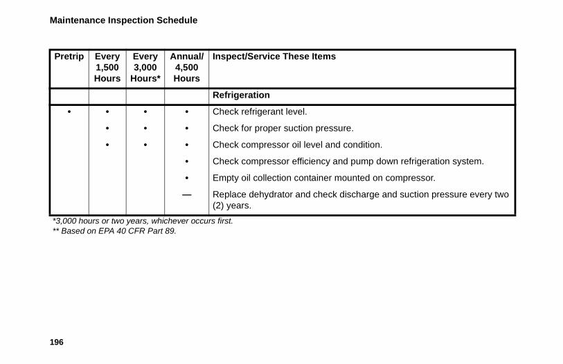
Maintenance Inspection Schedule
196
Refrigeration
• • • • Check refrigerant level.
• • • Check for proper suction pressure.
• • • Check compressor oil level and condition.
• Check compressor efficiency and pump down refrigeration system.
• Empty oil collection container mounted on compressor.
— Replace dehydrator and check discharge and suction pressure every two (2) years.
Pretrip Every 1,500 Hours
Every 3,000
Hours*
Annual/4,500 Hours
Inspect/Service These Items
*3,000 hours or two years, whichever occurs first.** Based on EPA 40 CFR Part 89.

Maintenance Inspection Schedule
197
Structural
• • • • Visually inspect unit for fluid leaks.
• • • • Visually inspect unit for damaged, loose or broken parts (includes air ducts and bulkheads).
• • • Inspect idlers for bearing wear (noise).
• • • Clean entire unit including condenser and evaporator coils and defrost drains.
• • • Check all unit and fuel tank mounting bolts, brackets, lines, hoses, etc.
Pretrip Every 1,500 Hours
Every 3,000
Hours*
Annual/4,500 Hours
Inspect/Service These Items
*3,000 hours or two years, whichever occurs first.** Based on EPA 40 CFR Part 89.

198
Serial Number LocationsUnit: Nameplates on the evaporator fan housing and on the roadside of the evaporator.
Engine: See the engine identification plate located on the engine valve cover.
Compressor: Stamped between the cylinders on the front end above the oil pump.
Figure 189: Compressor Serial Number Location

Serial Number Locations
199
Figure 190: Engine Serial Number Location
Figure 191: Unit Serial Number Plate Locations

Serial Number Locations
200
1. Unit Serial Number 2. Bill of Material Number 3. Unit Model4. Unit ID
Figure 192: Unit Serial Number Plate
ARA793
1 2
3
4

201
Emergency Cold Line
If you can’t get your rig rolling, and you have tried the Thermo King North American Service Directory (available from any Thermo King dealer) to reach a dealer without success, then call the Toll Free Emergency Cold Line Number (888) 887-2202.
The answering service at the factory will assist you in reaching a dealer to get the help you need. The Cold Line is answered 24 hours a day by personnel who will do their best to get you quick service at an authorized Thermo King Dealer.
AMA1585
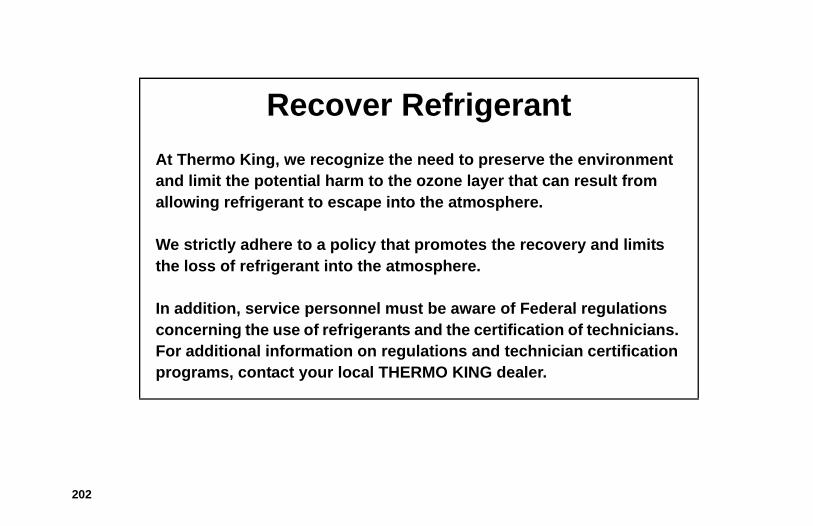
202
Recover Refrigerant
At Thermo King, we recognize the need to preserve the environment and limit the potential harm to the ozone layer that can result from allowing refrigerant to escape into the atmosphere.
We strictly adhere to a policy that promotes the recovery and limits the loss of refrigerant into the atmosphere.
In addition, service personnel must be aware of Federal regulations concerning the use of refrigerants and the certification of technicians. For additional information on regulations and technician certification programs, contact your local THERMO KING dealer.

203
CALIFORNIAProposition 65 Warning
Diesel exhaust is a chemical known to the State of California to cause cancer.
204
Aalarm codes 142
corrective action 145types 142
amber status light 33automatic start/stop safety precautions 12Bbattery inspection 35belt tension, specifications 178belts inspection 35Ccoils inspection 36compressor oil sight glass 28control panel 38
display 38keys 40
CYCLE-SENTRYstart-stop controls 24
Ddata logging 25
defrost 26defrost drain inspection 36Defrost key 39, 40, 48, 83door inspection 36EELC (extended life coolant) 21electrical components, specifications 182electrical control system, specifications 181electrical hazards 12electrical inspection 35electrical standby, specifications 184electronic throttling valve (ETV) 22Emergency Cold Line 201EMI 3000 22engine compartment components 28engine coolant level 35engine oil dipstick 28engine oil level 35engine, specifications 175enroute inspections 139

205
ETV (electronic throttling valve) 22extended life coolant (ELC) 21Ffirst aid for refrigerant 14first aid for refrigerant oil 14FreshSet 26front doors
opening 27fuel level 35fuses 29Hhigh pressure cutout switch 29high pressure relief valve 29HMI control panel 38Iintroduction 7Jjump starting 171Lloading procedures
enroute inspections 139post-loading inspection 138pre-loading inspection 136
low oil level switch 29low oil pressure switch 29Mmaintenance inspection schedule 193manual pretrip inspection 35microprocessor On/Off switch 38Mode key 40OOff key 39, 40, 48On key 39, 40, 47OptiSet Plus 26overload relay 29Ppost-loading inspection 138preheat buzzer 29pre-loading inspection 136pretrip inspection, manual 35

206
protection devices 28Rrear remote control panel 121receiver tank sight glass 28refrigerant oil safety 14refrigerant safety 12refrigeration system, specifications 179remote status light 32Ssafety precautions 11
automatic start/stop operation 12electrical hazards 12first aid for refrigerant 14first aid for refrigerant oil 14general safety practices 11refrigerant 12refrigerant oil 14
Serial Number Locations 198smart FETs 29SMART REEFER 2 (SR-2) Controller 23, 37
soft keys 40specifications
electric fuel heater 185SR-2 Controller 23, 37status light, remote 32structural inspection 35Uunit description 18Wwarranty 186

Operator’s Manual
Ingersoll Rand’s Climate Solutions sector delivers energy-effi cient HVACR solutions for customers globally. Its world class brands include Thermo King, the leader in transport temperature control and Trane, a provider of energy effi cient heating, ventilating and air conditioning systems, building and contracting services, parts support and advanced controls for commercial buildings and homes.
©2013 Ingersoll-Rand Company Printed in U.S.A.
Precedent™C-600
TK 55692-2-OP (Rev. 2, 12/15)