Embed Size (px)
Citation preview

Operator’s Manual
Operator’s Manual
Ingersoll Rand’s Climate Solutions sector delivers energy-effi cient HVACR solutions for customers globally. Its world class brands include Thermo King, the leader in transport temperature control and Trane, a provider of energy effi cient heating, ventilating and air conditioning systems, building and contracting services, parts support and advanced controls for commercial buildings and homes.
Ingersoll Rand’s Climate Solutions sector delivers energy-effi cient HVACR solutions for customers globally. Its world class brands include Thermo King, the leader in transport temperature control and Trane, a provider of energy effi cient heating, ventilating and air conditioning systems, building and contracting services, parts support and advanced controls for commercial buildings and homes.
©2013 Ingersoll-Rand Company Printed in U.S.A.
©2013 Ingersoll-Rand Company Printed in U.S.A.
TriPac EVOLUTIONAuxiliary Heating/Cooling
TemperatureManagement System
TK 55711-19-OP (Rev. 3, 12/17)
TriPac EVOLUTIONAuxiliary Heating/Cooling
TemperatureManagement System
TK 55711-19-OP (Rev. 3, 12/17)

Copyright© 2013 Thermo King Corp., Minneapolis, MN, USAPrinted in USA
TriPac™ EVOLUTION
TK 55711-19-OP (Rev. 3, 12/17)
2
DisclaimerThis manual is published for informational purposes only. Thermo King Corporation makes no representations orwarranties, express or implied, with respect to the information, recommendations and descriptions contained in this manualand such information, recommendations and descriptions should not be regarded as all-inclusive or covering allcontingencies. In the event you have any questions or require further information, please contact your local Thermo Kingdealer.
The procedures described herein should only be undertaken by suitably qualified personnel. Failure to implement theseprocedures correctly may cause damage to the Thermo King unit or other property or personal injury.
Thermo King Corporation and its affiliates shall have no liability in contract or tort (including negligence and/or strictliability) or otherwise, to any person or entity for any personal injury, property damage or any other direct, indirect, specialor consequential damage or liability whatsoever, arising out of or resulting from any actions by any person that are contraryto this manual or any of the information, recommendations or descriptions contained herein or the failure of any person toimplement the procedures described herein correctly or to follow caution and safety decals located on the Thermo Kingunit.
3
Table Of ContentsIntroduction . . . . . . . . . . . . . . . . . . . . . . . . . . . . . . . . . 5
Safety Precautions . . . . . . . . . . . . . . . . . . . . . . . . . . . 6General Practices . . . . . . . . . . . . . . . . . . . . . . . . . . . . . 6Refrigerant Oil . . . . . . . . . . . . . . . . . . . . . . . . . . . . . . . . 7Refrigerant . . . . . . . . . . . . . . . . . . . . . . . . . . . . . . . . . . 7First Aid . . . . . . . . . . . . . . . . . . . . . . . . . . . . . . . . . . . . . 8
First Aid—Refrigerant . . . . . . . . . . . . . . . . . . . . . . . 8First Aid—Refrigerant Oil . . . . . . . . . . . . . . . . . . . . 8
Low Voltage . . . . . . . . . . . . . . . . . . . . . . . . . . . . . . . . . 8Battery Installation and Cable Routing . . . . . . . . . . . . . 9Safety Decals . . . . . . . . . . . . . . . . . . . . . . . . . . . . . . . 10
Unit Description . . . . . . . . . . . . . . . . . . . . . . . . . . . . 11TriPac Standard Features . . . . . . . . . . . . . . . . . . . . . . 12TriPac System Components . . . . . . . . . . . . . . . . . . . . 12TriPac Options . . . . . . . . . . . . . . . . . . . . . . . . . . . . . . 12Auxiliary Power Unit (APU) . . . . . . . . . . . . . . . . . . . . . 13Condenser . . . . . . . . . . . . . . . . . . . . . . . . . . . . . . . . . 13Evaporator . . . . . . . . . . . . . . . . . . . . . . . . . . . . . . . . . 14Heater . . . . . . . . . . . . . . . . . . . . . . . . . . . . . . . . . . . . . 14HMI Controller . . . . . . . . . . . . . . . . . . . . . . . . . . . . . . . 15
Engine On/Off Switch . . . . . . . . . . . . . . . . . . . . . . . . . .15Control Box and Fuses . . . . . . . . . . . . . . . . . . . . . . . .16Driver Convenience Package . . . . . . . . . . . . . . . . . . .16Standby Truck Integration . . . . . . . . . . . . . . . . . . . . . .16Standby Truck Integration - with Dash-Mounted Selector Switch . . . . . . . . . . . . . . . . . . . . . . . . . . . . . .17Dual Remote Hour Meter . . . . . . . . . . . . . . . . . . . . . .17Remote Engine Hour Meter . . . . . . . . . . . . . . . . . . . .17Closed Loop Cooling . . . . . . . . . . . . . . . . . . . . . . . . . .17High Output Heater . . . . . . . . . . . . . . . . . . . . . . . . . . .17Diesel Particulate Filter (DPF) . . . . . . . . . . . . . . . . . . .17High Output Alternator . . . . . . . . . . . . . . . . . . . . . . . .17Arctic Package . . . . . . . . . . . . . . . . . . . . . . . . . . . . . .18Appearance Package - Top Cover . . . . . . . . . . . . . . .18Brushed Stainless Steel Condenser Cover . . . . . . . . .18Exhaust Tube Extension . . . . . . . . . . . . . . . . . . . . . . .18
Manual Pretrip Inspection . . . . . . . . . . . . . . . . . . . . .19
Operating Instructions . . . . . . . . . . . . . . . . . . . . . . .20HMI Control Panel Display . . . . . . . . . . . . . . . . . . . . . .20
On/Off Button . . . . . . . . . . . . . . . . . . . . . . . . . . . .21
Table Of Contents
4
Mode Selector . . . . . . . . . . . . . . . . . . . . . . . . . . . . 21Temperature Selector . . . . . . . . . . . . . . . . . . . . . . 22Fan Speed Selector . . . . . . . . . . . . . . . . . . . . . . . 23System Condition . . . . . . . . . . . . . . . . . . . . . . . . . 23Standby Indicator . . . . . . . . . . . . . . . . . . . . . . . . . 23Alarm Icon . . . . . . . . . . . . . . . . . . . . . . . . . . . . . . . 24Alarm Group Indicator . . . . . . . . . . . . . . . . . . . . . . 24Clearing Alarms . . . . . . . . . . . . . . . . . . . . . . . . . . 24
Operating Modes . . . . . . . . . . . . . . . . . . . . . . . . . . . . . 24Cool Mode . . . . . . . . . . . . . . . . . . . . . . . . . . . . . . . 24Heat Mode . . . . . . . . . . . . . . . . . . . . . . . . . . . . . . 25Fan Mode . . . . . . . . . . . . . . . . . . . . . . . . . . . . . . . 25Standby Mode (Option) . . . . . . . . . . . . . . . . . . . . . 26Standby Truck Integration (Option) . . . . . . . . . . . . 26Standby Truck Integration - with Dash-Mounted Selector Switch (Option) . . . . . . . . . . . . . . . . . . . . 27
Monitor Mode . . . . . . . . . . . . . . . . . . . . . . . . . . . . . . . . 27Activate . . . . . . . . . . . . . . . . . . . . . . . . . . . . . . . . . 27Deactivate . . . . . . . . . . . . . . . . . . . . . . . . . . . . . . . 27Operation . . . . . . . . . . . . . . . . . . . . . . . . . . . . . . . 27
Engine Load Management . . . . . . . . . . . . . . . . . . . . . 28Engine On/Off Switch . . . . . . . . . . . . . . . . . . . . . . . . . 28Alarm Codes . . . . . . . . . . . . . . . . . . . . . . . . . . . . . . . . 29
Alarm Notification . . . . . . . . . . . . . . . . . . . . . . . . . 29To Clear Alarm Codes . . . . . . . . . . . . . . . . . . . . . 31
Power Inverter (Option) . . . . . . . . . . . . . . . . . . . . . . 32Inverter Operation Warnings . . . . . . . . . . . . . . . . 32
Specifications . . . . . . . . . . . . . . . . . . . . . . . . . . . . . . 34Engine . . . . . . . . . . . . . . . . . . . . . . . . . . . . . . . . . . . . 34Electrical Control System . . . . . . . . . . . . . . . . . . . . . . 35Fuses . . . . . . . . . . . . . . . . . . . . . . . . . . . . . . . . . . . . . 36Air Conditioning System . . . . . . . . . . . . . . . . . . . . . . . 37Truck Sleeper Compartment Heater . . . . . . . . . . . . . 37
Maintenance Inspection Schedule . . . . . . . . . . . . . 38Engine . . . . . . . . . . . . . . . . . . . . . . . . . . . . . . . . . . . . 38Engine Oil Change Intervals . . . . . . . . . . . . . . . . . . . . 40Electrical . . . . . . . . . . . . . . . . . . . . . . . . . . . . . . . . . . . 41Structural . . . . . . . . . . . . . . . . . . . . . . . . . . . . . . . . . . 41Air Conditioning System . . . . . . . . . . . . . . . . . . . . . . . 42Heater . . . . . . . . . . . . . . . . . . . . . . . . . . . . . . . . . . . . . 43
TriPac Warranty . . . . . . . . . . . . . . . . . . . . . . . . . . . . 44
Serial Number Locations . . . . . . . . . . . . . . . . . . . . . 45
Emergency Cold Line . . . . . . . . . . . . . . . . . . . . . . . . 46
Recover Refrigerant . . . . . . . . . . . . . . . . . . . . . . . . . 47
CALIFORNIAProposition 65 Warning . . . . . . . . . . . 48

5
IntroductionThere is nothing complicated about operating and maintaining your Thermo King unit, but a few minutes studying this manual will be time well spent.
Performing pre-trip checks and enroute inspections on a regular basis will minimize on-the-road operating problems. A regular maintenance program will also help to keep your unit in top operating condition. If factory recommended procedures are followed, you will find that you have purchased the most efficient and dependable temperature control system available.
All service requirements, major and minor, should be handled by a Thermo King dealer for four very important reasons:
• They are equipped with the factory recommended tools toperform all service functions
• They have factory trained and certified technicians
• They have genuine Thermo King replacement parts
• The warranty on your new unit is valid only when therepair and replacement of component parts is performedby an authorized Thermo King dealer.
IMPORTANT: This manual is published for informational purposes only and the information furnished herein should not be considered as all-inclusive or meant to cover all contingencies. If more information is required, consult your Thermo King Service Directory for the location and telephone number of the local dealer.
6
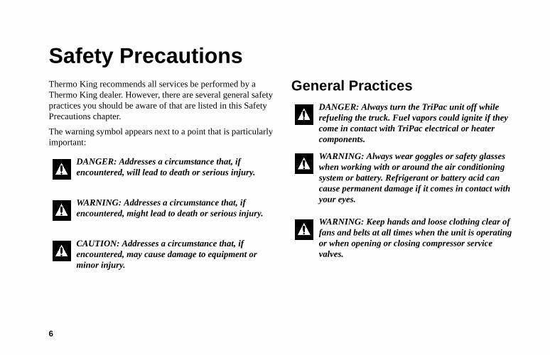
Safety PrecautionsThermo King recommends all services be performed by a Thermo King dealer. However, there are several general safety practices you should be aware of that are listed in this Safety Precautions chapter.
The warning symbol appears next to a point that is particularly important:
General Practices
DANGER: Addresses a circumstance that, if encountered, will lead to death or serious injury.
WARNING: Addresses a circumstance that, if encountered, might lead to death or serious injury.
CAUTION: Addresses a circumstance that, if encountered, may cause damage to equipment or minor injury.
DANGER: Always turn the TriPac unit off while refueling the truck. Fuel vapors could ignite if they come in contact with TriPac electrical or heater components.
WARNING: Always wear goggles or safety glasses when working with or around the air conditioning system or battery. Refrigerant or battery acid can cause permanent damage if it comes in contact with your eyes.
WARNING: Keep hands and loose clothing clear of fans and belts at all times when the unit is operating or when opening or closing compressor service valves.
Safety Precautions
7
Refrigerant OilObserve the following precautions when working with or around refrigerant oil:
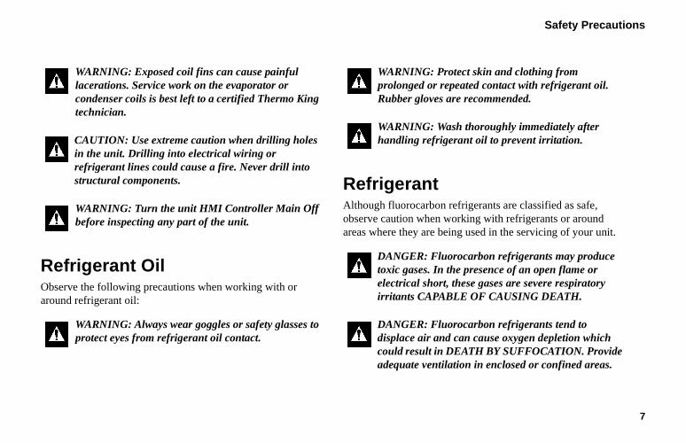
RefrigerantAlthough fluorocarbon refrigerants are classified as safe, observe caution when working with refrigerants or around areas where they are being used in the servicing of your unit.
WARNING: Exposed coil fins can cause painful lacerations. Service work on the evaporator or condenser coils is best left to a certified Thermo King technician.
CAUTION: Use extreme caution when drilling holes in the unit. Drilling into electrical wiring or refrigerant lines could cause a fire. Never drill into structural components.
WARNING: Turn the unit HMI Controller Main Off before inspecting any part of the unit.
WARNING: Always wear goggles or safety glasses to protect eyes from refrigerant oil contact.
WARNING: Protect skin and clothing from prolonged or repeated contact with refrigerant oil. Rubber gloves are recommended.
WARNING: Wash thoroughly immediately after handling refrigerant oil to prevent irritation.
DANGER: Fluorocarbon refrigerants may produce toxic gases. In the presence of an open flame or electrical short, these gases are severe respiratory irritants CAPABLE OF CAUSING DEATH.
DANGER: Fluorocarbon refrigerants tend to displace air and can cause oxygen depletion which could result in DEATH BY SUFFOCATION. Provide adequate ventilation in enclosed or confined areas.
Safety Precautions
8
First Aid
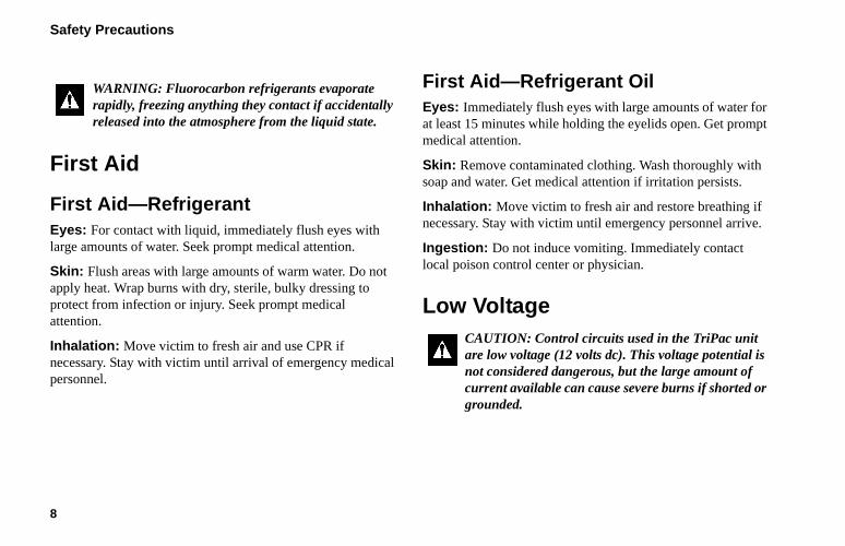
First Aid—RefrigerantEyes: For contact with liquid, immediately flush eyes with large amounts of water. Seek prompt medical attention.
Skin: Flush areas with large amounts of warm water. Do not apply heat. Wrap burns with dry, sterile, bulky dressing to protect from infection or injury. Seek prompt medical attention.
Inhalation: Move victim to fresh air and use CPR if necessary. Stay with victim until arrival of emergency medical personnel.
First Aid—Refrigerant OilEyes: Immediately flush eyes with large amounts of water for at least 15 minutes while holding the eyelids open. Get prompt medical attention.
Skin: Remove contaminated clothing. Wash thoroughly with soap and water. Get medical attention if irritation persists.
Inhalation: Move victim to fresh air and restore breathing if necessary. Stay with victim until emergency personnel arrive.
Ingestion: Do not induce vomiting. Immediately contact local poison control center or physician.
Low Voltage
WARNING: Fluorocarbon refrigerants evaporate rapidly, freezing anything they contact if accidentally released into the atmosphere from the liquid state.
CAUTION: Control circuits used in the TriPac unit are low voltage (12 volts dc). This voltage potential is not considered dangerous, but the large amount of current available can cause severe burns if shorted or grounded.
Safety Precautions
9
Battery Installation and Cable Routing
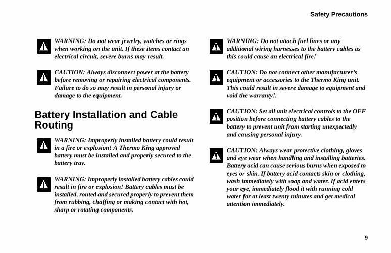
WARNING: Do not wear jewelry, watches or rings when working on the unit. If these items contact an electrical circuit, severe burns may result.
CAUTION: Always disconnect power at the battery before removing or repairing electrical components. Failure to do so may result in personal injury or damage to the equipment.
WARNING: Improperly installed battery could result in a fire or explosion! A Thermo King approved battery must be installed and properly secured to the battery tray.
WARNING: Improperly installed battery cables could result in fire or explosion! Battery cables must be installed, routed and secured properly to prevent them from rubbing, chaffing or making contact with hot, sharp or rotating components.
WARNING: Do not attach fuel lines or any additional wiring harnesses to the battery cables as this could cause an electrical fire!
CAUTION: Do not connect other manufacturer’s equipment or accessories to the Thermo King unit. This could result in severe damage to equipment and void the warranty!.
CAUTION: Set all unit electrical controls to the OFF position before connecting battery cables to the battery to prevent unit from starting unexpectedly and causing personal injury.
CAUTION: Always wear protective clothing, gloves and eye wear when handling and installing batteries. Battery acid can cause serious burns when exposed to eyes or skin. If battery acid contacts skin or clothing, wash immediately with soap and water. If acid enters your eye, immediately flood it with running cold water for at least twenty minutes and get medical attention immediately.
Safety Precautions
10
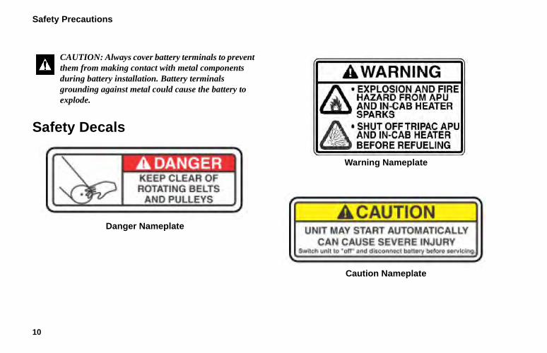
Safety Decals
Danger Nameplate
Warning Nameplate
Caution Nameplate
CAUTION: Always cover battery terminals to prevent them from making contact with metal components during battery installation. Battery terminals grounding against metal could cause the battery to explode.
11
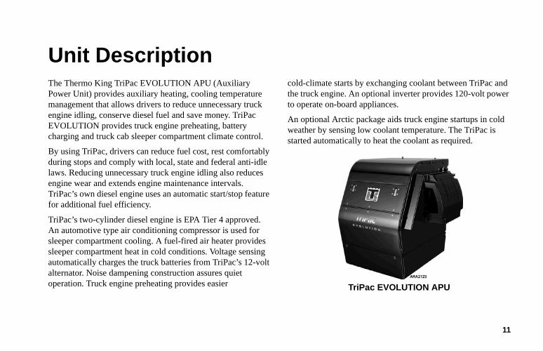
Unit DescriptionThe Thermo King TriPac EVOLUTION APU (Auxiliary Power Unit) provides auxiliary heating, cooling temperature management that allows drivers to reduce unnecessary truck engine idling, conserve diesel fuel and save money. TriPac EVOLUTION provides truck engine preheating, battery charging and truck cab sleeper compartment climate control.
By using TriPac, drivers can reduce fuel cost, rest comfortably during stops and comply with local, state and federal anti-idle laws. Reducing unnecessary truck engine idling also reduces engine wear and extends engine maintenance intervals. TriPac’s own diesel engine uses an automatic start/stop feature for additional fuel efficiency.
TriPac’s two-cylinder diesel engine is EPA Tier 4 approved. An automotive type air conditioning compressor is used for sleeper compartment cooling. A fuel-fired air heater provides sleeper compartment heat in cold conditions. Voltage sensing automatically charges the truck batteries from TriPac’s 12-volt alternator. Noise dampening construction assures quiet operation. Truck engine preheating provides easier
cold-climate starts by exchanging coolant between TriPac and the truck engine. An optional inverter provides 120-volt power to operate on-board appliances.
An optional Arctic package aids truck engine startups in cold weather by sensing low coolant temperature. The TriPac is started automatically to heat the coolant as required.
TriPac EVOLUTION APU
Unit Description
12
TriPac Standard Features• Easy to operate Human Machine Interface (HMI)
Controller
• Truck cab sleeper compartment cooling and heating fordriver comfort in all climates
• Truck engine preheating for easy starts in cold climates
• Truck battery charging with automatic low voltage sensing
• 9.0 hp 2 cylinder diesel engine - EPA Tier 4• Thermo King TK 15 compressor for air conditioning
• Diesel fuel-fired sleeper compartment air heater
• 65 amp alternator standard
• Noise-dampening construction for quiet operation
• Automatic start/stop operation for maximum fuelefficiency
TriPac System Components• Auxiliary Power Unit (APU)• Condenser
• Evaporator
• Heater
• HMI Controller
• Engine On/Off Switch
• Control Box and Fuses
TriPac Options• Driver Convenience Package
• Standby Truck Integration
• Standby Truck Integration with Dash-Mounted Switch
• Dual Remote Hour Meter• Remote Engine Hour Meter
• Closed Loop Cooling
• High Output Heater
• Diesel Particulate Filter (DPF)
• High Output Alternator
• Arctic Package• Appearance Package (diamond plate top cover)
• Brushed Stainless Steel Condenser Cover
• Exhaust Tube Extension
Unit Description
13
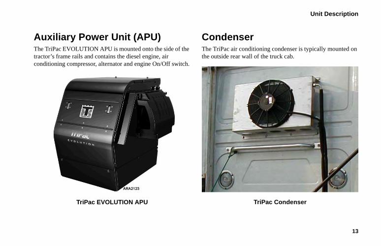
Auxiliary Power Unit (APU)The TriPac EVOLUTION APU is mounted onto the side of the tractor’s frame rails and contains the diesel engine, air conditioning compressor, alternator and engine On/Off switch.
TriPac EVOLUTION APU
Condenser The TriPac air conditioning condenser is typically mounted on the outside rear wall of the truck cab.
TriPac Condenser
Unit Description
14
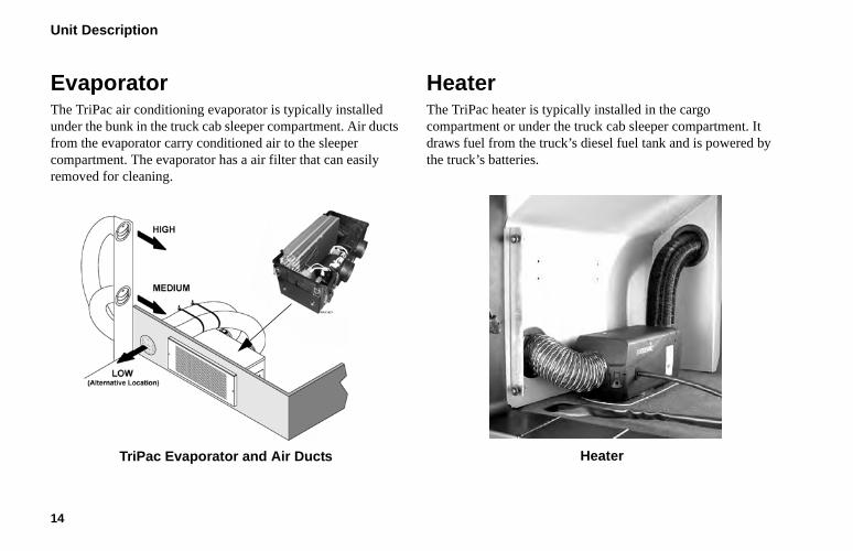
EvaporatorThe TriPac air conditioning evaporator is typically installed under the bunk in the truck cab sleeper compartment. Air ducts from the evaporator carry conditioned air to the sleeper compartment. The evaporator has a air filter that can easily removed for cleaning.
TriPac Evaporator and Air Ducts
HeaterThe TriPac heater is typically installed in the cargo compartment or under the truck cab sleeper compartment. It draws fuel from the truck’s diesel fuel tank and is powered by the truck’s batteries.
Heater
Unit Description
15
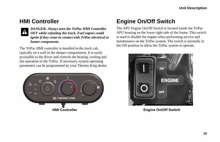
HMI Controller
The TriPac HMI controller is installed in the truck cab, typically on a wall in the sleeper compartment. It is easily accessible to the driver and controls the heating, cooling and fan operation of the TriPac. If necessary, system operating parameters can be programmed by your Thermo King dealer.
HMI Controller
Engine On/Off SwitchThe APU Engine On/Off Switch is located inside the TriPac APU housing on the lower right side of the frame. This switch is used to disable the engine when performing service and maintenance on the TriPac system. The switch is normally in the ON position to allow the TriPac system to operate.
Engine On/Off Switch
DANGER: Always turn the TriPac HMI Controller OFF while refueling the truck. Fuel vapors could ignite if they come in contact with TriPac electrical or heater components.
Unit Description
16
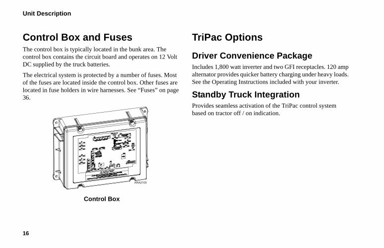
Control Box and FusesThe control box is typically located in the bunk area. The control box contains the circuit board and operates on 12 Volt DC supplied by the truck batteries.
The electrical system is protected by a number of fuses. Most of the fuses are located inside the control box. Other fuses are located in fuse holders in wire harnesses. See “Fuses” on page 36.
Control Box
TriPac Options
Driver Convenience PackageIncludes 1,800 watt inverter and two GFI receptacles. 120 amp alternator provides quicker battery charging under heavy loads. See the Operating Instructions included with your inverter.
Standby Truck IntegrationProvides seamless activation of the TriPac control system based on tractor off / on indication.
ARA2105
Unit Description
17
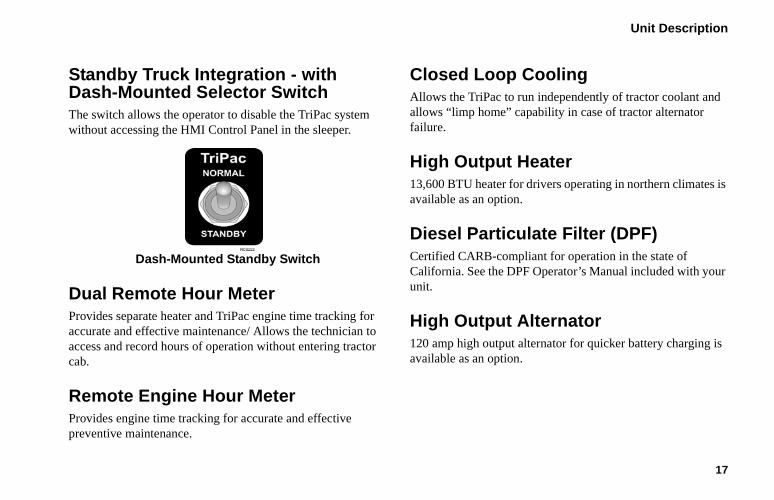
Standby Truck Integration - with Dash-Mounted Selector Switch The switch allows the operator to disable the TriPac system without accessing the HMI Control Panel in the sleeper.
Dash-Mounted Standby Switch
Dual Remote Hour Meter Provides separate heater and TriPac engine time tracking for accurate and effective maintenance/ Allows the technician to access and record hours of operation without entering tractor cab.
Remote Engine Hour MeterProvides engine time tracking for accurate and effective preventive maintenance.
Closed Loop CoolingAllows the TriPac to run independently of tractor coolant and allows “limp home” capability in case of tractor alternator failure.
High Output Heater13,600 BTU heater for drivers operating in northern climates is available as an option.
Diesel Particulate Filter (DPF) Certified CARB-compliant for operation in the state of California. See the DPF Operator’s Manual included with your unit.
High Output Alternator120 amp high output alternator for quicker battery charging is available as an option.
Unit Description
18
Arctic PackageMonitors tractor engine coolant temperature and automatically starts the TriPac to heat the shared engine coolant. Reduces cold weather starting issues for tractor even after extended periods of no operation in clod temperatures.
Appearance Package - Top CoverDiamond plate top cover is available as an option.
Brushed Stainless Steel Condenser CoverA brushed stainless steel condenser cover is available as an option.
Exhaust Tube ExtensionA exhaust tube extension is available as an option.
19
Manual Pretrip InspectionPretrip inspections are an important part of a preventative maintenance program designed to minimize operating problems and breakdowns. Perform this pretrip inspection before every trip.
NOTE: Pretrip inspections are not intended to take the place of regular maintenance inspections.
Before Starting the TriPac UnitEngine: Check engine oil level. Check coolant level if equipped with optional closed loop cooling. Coolant should be visible in coolant tank sight glass.
Belts: Make sure the TriPac APU belts are in good condition and adjusted to the proper tension. For more information about belt tension, see the Specifications chapter.
Electrical: Check the electrical connections to make sure they are securely fastened. Wires and terminals should be free of corrosion, cracks, and moisture.
Structural: Visually inspect the unit for leaks, loose or broken parts, and other damage.
Coils: Make sure the condenser, evaporator and pre-cooler coils are clean and free of debris.
Heater: Check exhaust pipe and intake tube.
General: Listen for unusual noises and vibrations or fluid leaks.
20
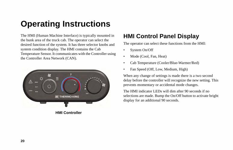
Operating InstructionsThe HMI (Human Machine Interface) is typically mounted in the bunk area of the truck cab. The operator can select the desired function of the system. It has three selector knobs and system condition display. The HMI contains the Cab Temperature Sensor. It communicates with the Controller using the Controller Area Network (CAN).
HMI Controller
HMI Control Panel DisplayThe operator can select these functions from the HMI:
• System On/Off
• Mode (Cool, Fan, Heat)
• Cab Temperature (Cooler/Blue-Warmer/Red)
• Fan Speed (Off, Low, Medium, High)
When any change of settings is made there is a two second delay before the controller will recognize the new setting. This prevents momentary or accidental mode changes.
The HMI indicator LEDs will dim after 90 seconds if no selections are made. Bump the On/Off button to activate bright display for an additional 90 seconds.
Operating Instructions
21
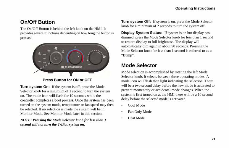
On/Off Button The On/Off Button is behind the left knob on the HMI. It provides several functions depending on how long the button is pressed.
Press Button for ON or OFF
Turn system On: If the system is off, press the Mode Selector knob for a minimum of 1 second to turn the system on. The mode icon will flash for 10 seconds while the controller completes a boot process. Once the system has been turned on the system mode, temperature or fan speed may then be selected. If no selection is made the system will be in Monitor Mode. See Monitor Mode later in this section.
NOTE: Pressing the Mode Selector knob for less than 1 second will not turn the TriPac system on.
Turn system Off: If system is on, press the Mode Selector knob for a minimum of 2 seconds to turn the system off.
Display System Status: If system is on but display has dimmed, press the Mode Selector knob for less than 1 second to restore display to full brightness. The display will automatically dim again in about 90 seconds. Pressing the Mode Selector knob for less than 1 second is referred to as a “Bump”.
Mode SelectorMode selection is accomplished by rotating the left Mode Selector knob. It selects between three operating modes. A mode icon will flash then light indicating the selection. There will be a two second delay before the new mode is activated to prevent momentary or accidental mode changes. When the system is first turned on at the HMI there will be a 10 second delay before the selected mode is activated.
• Cool Mode
• Fan Only Mode
• Heat Mode
Operating Instructions
22
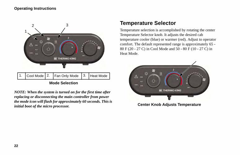
NOTE: When the system is turned on for the first time after replacing or disconnecting the main controller from power the mode icon will flash for approximately 60 seconds. This is initial boot of the micro processor.
Temperature Selector Temperature selection is accomplished by rotating the center Temperature Selector knob. It adjusts the desired cab temperature cooler (blue) or warmer (red). Adjust to operator comfort. The default represented range is approximately 65 - 80 F (20 - 27 C) in Cool Mode and 50 - 80 F (10 - 27 C) in Heat Mode.
Center Knob Adjusts Temperature
1. Cool Mode 2. Fan Only Mode 3. Heat Mode
Mode Selection
1
2 3
Operating Instructions
23
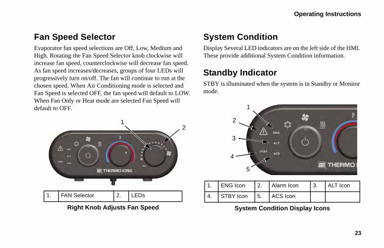
Fan Speed Selector Evaporator fan speed selections are Off, Low, Medium and High. Rotating the Fan Speed Selector knob clockwise will increase fan speed, counterclockwise will decrease fan speed. As fan speed increases/decreases, groups of four LEDs will progressively turn on/off. The fan will continue to run at the chosen speed. When Air Conditioning mode is selected and Fan Speed is selected OFF, the fan speed will default to LOW. When Fan Only or Heat mode are selected Fan Speed will default to OFF.
System Condition Display Several LED indicators are on the left side of the HMI. These provide additional System Condition information.
Standby Indicator STBY is illuminated when the system is in Standby or Monitor mode.
1. FAN Selector 2. LEDs
Right Knob Adjusts Fan Speed
12
1. ENG Icon 2. Alarm Icon 3. ALT Icon
4. STBY Icon 5. ACS Icon
System Condition Display Icons
1
2
4
3
5
Operating Instructions
24
Alarm Icon If the system has an active alarm the Alarm Icon will illuminate. It will be Red for shutdown alarms and Yellow for Check alarms.
Alarm Group Indicator System shutdown alarms have been organized into three general groups to help diagnosis. When a shutdown alarm is generated the red Alarm Icon and the corresponding Alarm Group name will illuminate.
• [ENG] are APU engine related alarms.
• [ALT] are alternator or charging system alarms.
• [ACS] are air conditioning system related alarms.
Clearing Alarms Alarm codes can be cleared by turning the controller off and back on again. If the condition that caused the alarm still exists, the alarm will return. Refer to the TriPac EVOLUTION
Diagnostic Manual TK 55739 for more information about alarm codes. Contact the nearest Thermo King dealer if alarms continue to appear.
Operating Modes
Cool Mode When Cool Mode is selected at the Mode Selector knob, the HMI Control Panel uses the Cab Temperature Sensor to measure sleeper compartment temperature. If it is above the temperature selected by the Setpoint Selector knob, the APU engine will begin a start sequence (if not already running). The evaporator fan is defaulted ON and will run in low or the speed selected by the Fan Speed Selector knob. The compressor clutch will engage 60 seconds after a successful engine start. The system will cool the sleeper compartment until it falls to the selected setpoint temperature. The compressor clutch will disengage but the APU engine will continue to run for several minutes based on the Engine Delay Timer setting (default 8 minutes). The evaporator fan will continue to run at the
Operating Instructions
25
selected speed. If sleeper compartment temperature rises above setpoint by more than the Dead Band setting (default 3 F) during this time the compressor clutch will re-engage.
During normal air conditioning operation the compressor clutch may cycle on and off with no alarm. The evaporator fan will continue to run. The system is monitoring the Evaporator Coil Temperature sensor to prevent frost buildup on the evaporator coil. If coil temperature falls below 32 F the compressor clutch is de-energized. When coil temperature rises above 45 F the compressor clutch is energized.
The APU engine will shut down when the sleeper compartment temperature remains near setpoint and the truck batteries are charged. The evaporator fan will continue to run. If sleeper compartment temperature rises above setpoint by more than the Dead Band setting (default 3 F) the APU engine will restart and compressor clutch will re-engage. Battery voltage sensing and engine coolant temperature sensing are enabled for the APU. Refer to Monitor Mode.
Heat Mode The air heater is a separate module that heats the sleeper compartment to the setpoint selected with the Temperature Selector knob. Sleeper compartment temperature is sensed inside the air heater, it does not use the Cab Temperature Sensor on the HMI. All heater function is controlled by a separate module inside the heater. The TriPac evaporator fan is defaulted to OFF when Heat Mode is selected. It can be turned on to provide additional air circulation. Battery voltage sensing and engine coolant temperature sensing are enabled for the APU. Refer to Monitor Mode.
Fan Mode The TriPac evaporator fan can be turned on with the Fan Speed Selector knob to provide additional air circulation in the sleeper compartment and truck cab. Three fan speeds can be selected (Low, Medium, High). LEDs around the Fan Speed Selector will indicate the selected speed. Battery voltage sensing and engine coolant temperature sensing are enabled for the APU. Refer to Monitor Mode.
Operating Instructions
26
Standby Mode (Option) The optional TriPac Standby Mode allows the system to be controlled by an external switch input. This is typically the truck ignition using the optional Standby Truck Integration. The feature is used to disable the TriPac APU when the truck engine is running. When the truck ignition switch is in the run position, a voltage signal is sent to the controller. The TriPac system will enter Standby Mode. The following occurs when the TriPac system is in Standby Mode:
• The STBY indicator on the HMI will illuminate.
• Air conditioning, fan or heat operation will terminate.
• The APU engine will stop.
• The TriPac controller remains on but will not respond to any operation requests, such as low battery voltage or low coolant temperature.
Standby Truck Integration (Option) An optional wire harness connects the truck ignition switch to an input connection on the TriPac interface board. The board monitors voltage on this circuit.
• Truck ignition switch is in the Off or Acc position. If the TriPac system is turned on the unit operates normally.
• Truck ignition switch is in the Start or On position. The TriPac unit is forced to Standby mode. The HMI Controller STBY indicator will illuminate.
Operating Instructions
27
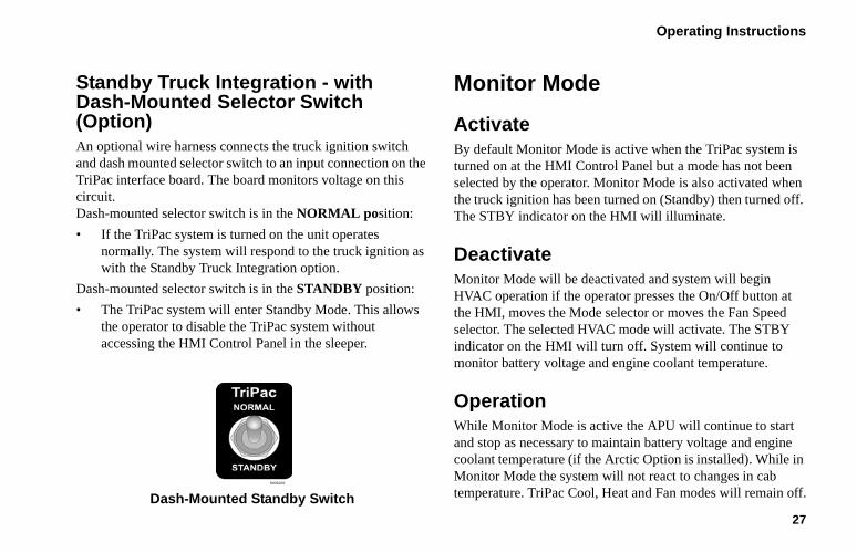
Standby Truck Integration - with Dash-Mounted Selector Switch (Option) An optional wire harness connects the truck ignition switch and dash mounted selector switch to an input connection on the TriPac interface board. The board monitors voltage on this circuit. Dash-mounted selector switch is in the NORMAL position:
• If the TriPac system is turned on the unit operatesnormally. The system will respond to the truck ignition aswith the Standby Truck Integration option.
Dash-mounted selector switch is in the STANDBY position:
• The TriPac system will enter Standby Mode. This allowsthe operator to disable the TriPac system withoutaccessing the HMI Control Panel in the sleeper.
Dash-Mounted Standby Switch
Monitor Mode
Activate By default Monitor Mode is active when the TriPac system is turned on at the HMI Control Panel but a mode has not been selected by the operator. Monitor Mode is also activated when the truck ignition has been turned on (Standby) then turned off. The STBY indicator on the HMI will illuminate.
Deactivate Monitor Mode will be deactivated and system will begin HVAC operation if the operator presses the On/Off button at the HMI, moves the Mode selector or moves the Fan Speed selector. The selected HVAC mode will activate. The STBY indicator on the HMI will turn off. System will continue to monitor battery voltage and engine coolant temperature.
Operation While Monitor Mode is active the APU will continue to start and stop as necessary to maintain battery voltage and engine coolant temperature (if the Arctic Option is installed). While in Monitor Mode the system will not react to changes in cab temperature. TriPac Cool, Heat and Fan modes will remain off.

Operating Instructions
28
Battery voltage sensing is enabled. When battery voltage falls to the level set by Battery Voltage Restart Value (default 12.2 Vdc) the APU engine will start so it can charge batteries. It will continue to run until the Charge Current Shutoff Value setting has been reached (default 12 amps).
If the Arctic Option is installed and enabled, truck engine coolant temperature sensing will occur. If engine coolant temperature at WT2 falls below 35 F the APU engine will start to warm the truck engine. It will continue to run until returning coolant temperature rises to 55 F.
Monitor Mode may be disabled. If disabled the system will return to the mode it was in when the truck ignition was turned on.
NOTE: This is not the recommended setting. Refer to the TriPac EVOLUTION Diagnostic Manual TK 55739 Section 3, Software Settings, Switch to Monitor for more information.
Engine Load Management To maintain Tier 4 engine emission levels, engine load may be reduced under some conditions.
Engine On/Off Switch
The Engine On/Off Switch is located inside the TriPac APU housing on the lower right side of the frame. This switch must be in the On position for the TriPac engine to operate.
Engine On/Off Switch
WARNING: The unit may start automatically without warning if the Engine On/Off Switch is in the On position.
WARNING: Immediately stand clear when the preheat buzzer sounds. This indicates that the engine is preheating and will start shortly. If the engine is hot, preheat time will only be a few seconds.
Operating Instructions
29
The APU Engine On/Off Switch functions as a service switch. It allows maintenance personnel to disable the APU engine. This assures the engine will not crank even if the HMI On/Off button is pressed on.
When the Engine On/Off switch is placed in the Off position:
• If the TriPac system is OFF and the TriPac HMI On/Offbutton is pressed, no shutdown alarm will generate.Theengine will not start.
• If the TriPac system is ON but the APU engine is notrunning, no shutdown alarm will generate. The engine willnot start.
• If the TriPac engine is running, the engine will stop and ashutdown alarm (code 35) will generate in the [ENG]group. The engine will not restart.
Alarm Codes
Alarm Notification The TriPac control system continually monitors operation and can generate several alarm codes. If the unit has an alarm condition the operator will be notified by an illuminated Alarm Icon on the HMI Control Panel. The icon can be Yellow or Red.
Operating Instructions
30
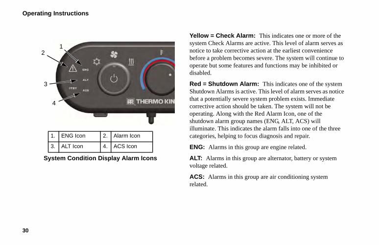
Yellow = Check Alarm: This indicates one or more of the system Check Alarms are active. This level of alarm serves as notice to take corrective action at the earliest convenience before a problem becomes severe. The system will continue to operate but some features and functions may be inhibited or disabled.
Red = Shutdown Alarm: This indicates one of the system Shutdown Alarms is active. This level of alarm serves as notice that a potentially severe system problem exists. Immediate corrective action should be taken. The system will not be operating. Along with the Red Alarm Icon, one of the shutdown alarm group names (ENG, ALT, ACS) will illuminate. This indicates the alarm falls into one of the three categories, helping to focus diagnosis and repair.
ENG: Alarms in this group are engine related.
ALT: Alarms in this group are alternator, battery or system voltage related.
ACS: Alarms in this group are air conditioning system related.
1. ENG Icon 2. Alarm Icon
3. ALT Icon 4. ACS Icon
System Condition Display Alarm Icons
12
3
4
Operating Instructions
31
To Clear Alarm CodesIf the alarm icon is Red, first note the alarm group that is illuminated on the HMI display (ENG, ALT, ACS). Use the HMI Control Panel System On/Off button to turn the TriPac unit off. Resolve the condition that caused the alarm. Use the HMI Control Panel System On/Off button to turn the TriPac unit on. Any active alarms will be cleared.
NOTE: If the alarm condition still exists the alarm will return.
Active alarms and those recently cleared by the operator can be read and cleared by a Thermo King service technician.
32
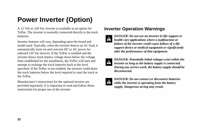
Power Inverter (Option)A 12 Vdc to 120 Vac inverter is available as an option for TriPac. The inverter is normally connected directly to the truck batteries.
Inverter features will vary, depending upon the brand and model used. Typically, when the inverter detects an AC load, it automatically turns on and converts DC to AC power for onboard 120 Vac devices. If the TriPac is enabled and the inverter draws truck battery voltage down below the voltage limit established for the installation, the TriPac will start and attempt to recharge the truck batteries back to the level specified. If the TriPac is not enabled, the inverter could drain the truck batteries below the level required to start the truck or the TriPac.
Manufacturer’s instructions for the optional inverter are provided separately. It is important to read and follow those instructions for proper use of the inverter.
Inverter Operation Warnings
DANGER: Do not use an inverter in life support or health care applications where a malfunction or failure of the inverter could cause failure of a life support device or medical equipment or significantly alter the performance of that equipment.
DANGER: Potentially lethal voltages exist within the inverter as long as the battery supply is connected. During any service work, the battery supply should be disconnected.
DANGER: Do not connect or disconnect batteries while the inverter is operating from the battery supply. Dangerous arcing may result.
Power Inverter (Option)
33
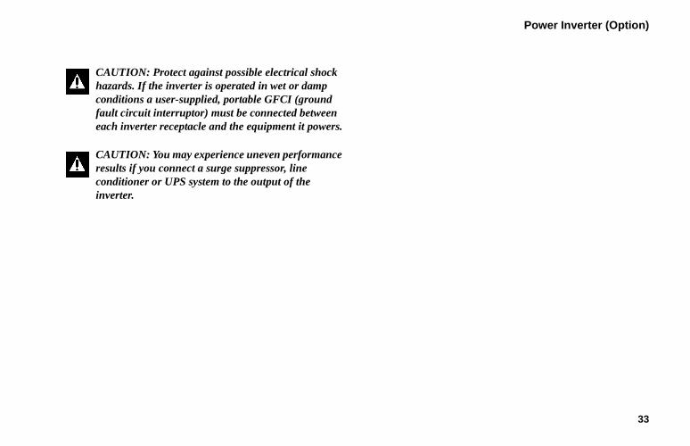
CAUTION: Protect against possible electrical shock hazards. If the inverter is operated in wet or damp conditions a user-supplied, portable GFCI (ground fault circuit interruptor) must be connected between each inverter receptacle and the equipment it powers.
CAUTION: You may experience uneven performance results if you connect a surge suppressor, line conditioner or UPS system to the output of the inverter.
34
Specifications
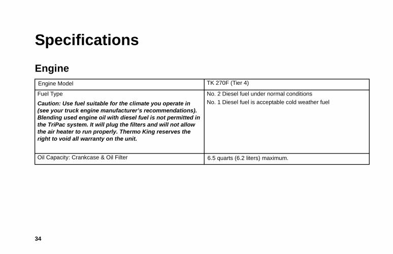
EngineEngine Model TK 270F (Tier 4)
Fuel Type
Caution: Use fuel suitable for the climate you operate in (see your truck engine manufacturer’s recommendations). Blending used engine oil with diesel fuel is not permitted in the TriPac system. It will plug the filters and will not allow the air heater to run properly. Thermo King reserves the right to void all warranty on the unit.
No. 2 Diesel fuel under normal conditions
No. 1 Diesel fuel is acceptable cold weather fuel
Oil Capacity: Crankcase & Oil Filter 6.5 quarts (6.2 liters) maximum.
Specifications
35
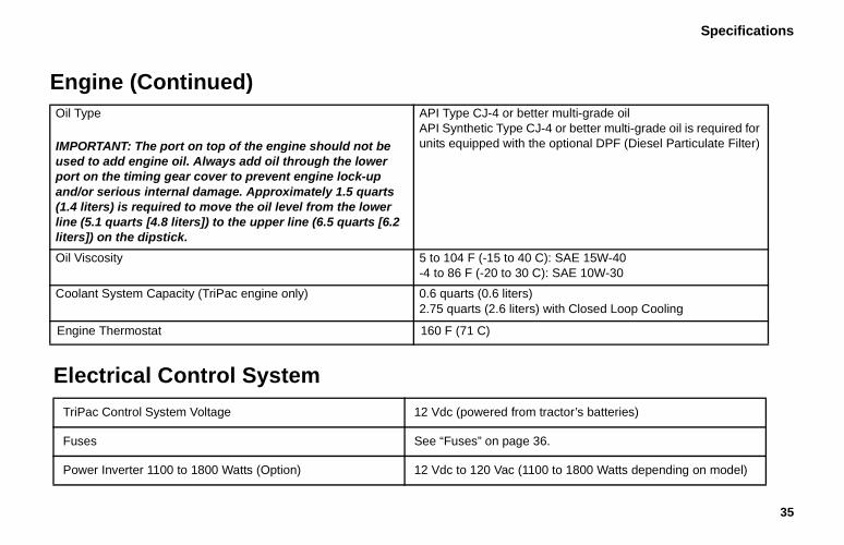
Oil Type
IMPORTANT: The port on top of the engine should not be used to add engine oil. Always add oil through the lower port on the timing gear cover to prevent engine lock-up and/or serious internal damage. Approximately 1.5 quarts (1.4 liters) is required to move the oil level from the lower line (5.1 quarts [4.8 liters]) to the upper line (6.5 quarts [6.2 liters]) on the dipstick.
API Type CJ-4 or better multi-grade oilAPI Synthetic Type CJ-4 or better multi-grade oil is required for units equipped with the optional DPF (Diesel Particulate Filter)
Oil Viscosity 5 to 104 F (-15 to 40 C): SAE 15W-40-4 to 86 F (-20 to 30 C): SAE 10W-30
Coolant System Capacity (TriPac engine only) 0.6 quarts (0.6 liters) 2.75 quarts (2.6 liters) with Closed Loop Cooling
Engine Thermostat 160 F (71 C)
Engine (Continued)
Electrical Control System
TriPac Control System Voltage 12 Vdc (powered from tractor’s batteries)
Fuses See “Fuses” on page 36.
Power Inverter 1100 to 1800 Watts (Option) 12 Vdc to 120 Vac (1100 to 1800 Watts depending on model)
Sp
36
ecifications
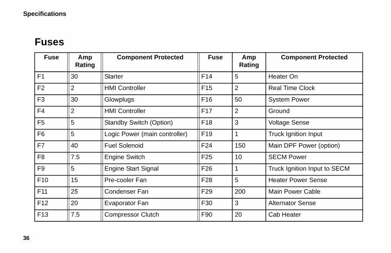
FusesFuse Amp
RatingComponent Protected Fuse Amp
RatingComponent Protected
F1 30 Starter F14 5 Heater On
F2 2 HMI Controller F15 2 Real Time Clock
F3 30 Glowplugs F16 50 System Power
F4 2 HMI Controller F17 2 Ground
F5 5 Standby Switch (Option) F18 3 Voltage Sense
F6 5 Logic Power (main controller) F19 1 Truck Ignition Input
F7 40 Fuel Solenoid F24 150 Main DPF Power (option)
F8 7.5 Engine Switch F25 10 SECM Power
F9 5 Engine Start Signal F26 1 Truck Ignition Input to SECM
F10 15 Pre-cooler Fan F28 5 Heater Power Sense
F11 25 Condenser Fan F29 200 Main Power Cable
F12 20 Evaporator Fan F30 3 Alternator Sense
F13 7.5 Compressor Clutch F90 20 Cab Heater
Specifications
37
Air Conditioning SystemThe TriPac air conditioning system must be serviced by a authorized Thermo King Dealer.
Truck Sleeper Compartment HeaterThe TriPac heater system must be serviced by a authorized Thermo King Dealer.
38
Maintenance Inspection Schedule
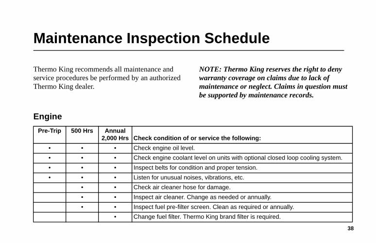
Thermo King recommends all maintenance and service procedures be performed by an authorized Thermo King dealer.
NOTE: Thermo King reserves the right to deny warranty coverage on claims due to lack of maintenance or neglect. Claims in question must be supported by maintenance records.
Engine
Pre-Trip 500 Hrs Annual 2,000 Hrs Check condition of or service the following:
• • • Check engine oil level.
• • • Check engine coolant level on units with optional closed loop cooling system.
• • • Inspect belts for condition and proper tension.
• • • Listen for unusual noises, vibrations, etc.
• • Check air cleaner hose for damage.
• • Inspect air cleaner. Change as needed or annually.
• • Inspect fuel pre-filter screen. Clean as required or annually.
• Change fuel filter. Thermo King brand filter is required.
Maintenance Inspection Schedule
39
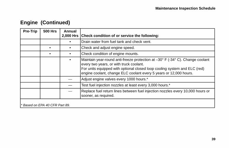
• Drain water from fuel tank and check vent.
• • Check and adjust engine speed.
• • Check condition of engine mounts.
• Maintain year-round anti-freeze protection at –30° F (-34° C). Change coolant every two years, or with truck coolant.For units equipped with optional closed loop cooling system and ELC (red) engine coolant, change ELC coolant every 5 years or 12,000 hours.
— Adjust engine valves every 1000 hours.*
— Test fuel injection nozzles at least every 3,000 hours.*
— Replace fuel return lines between fuel injection nozzles every 10,000 hours or sooner, as required.
* Based on EPA 40 CFR Part 89.
Engine (Continued) Pre-Trip 500 Hrs Annual
2,000 Hrs Check condition of or service the following:
Ma
40
intenance Inspection Schedule
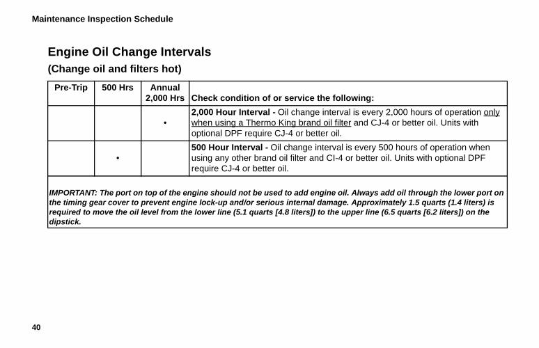
Engine Oil Change Intervals(Change oil and filters hot)
Pre-Trip 500 Hrs Annual 2,000 Hrs Check condition of or service the following:
•2,000 Hour Interval - Oil change interval is every 2,000 hours of operation only when using a Thermo King brand oil filter and CJ-4 or better oil. Units with optional DPF require CJ-4 or better oil.
•500 Hour Interval - Oil change interval is every 500 hours of operation when using any other brand oil filter and CI-4 or better oil. Units with optional DPF require CJ-4 or better oil.
IMPORTANT: The port on top of the engine should not be used to add engine oil. Always add oil through the lower port on the timing gear cover to prevent engine lock-up and/or serious internal damage. Approximately 1.5 quarts (1.4 liters) is required to move the oil level from the lower line (5.1 quarts [4.8 liters]) to the upper line (6.5 quarts [6.2 liters]) on the dipstick.
Maintenance Inspection Schedule
41
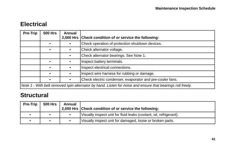
ElectricalPre-Trip 500 Hrs Annual
2,000 Hrs Check condition of or service the following:
• • Check operation of protection shutdown devices.
• • Check alternator voltage.
• Check alternator bearings. See Note 1.
• • Inspect battery terminals.
• • Inspect electrical connections.
• • Inspect wire harness for rubbing or damage.
• • Check electric condenser, evaporator and pre-cooler fans.
Note 1 - With belt removed spin alternator by hand. Listen for noise and ensure that bearings roll freely.
StructuralPre-Trip 500 Hrs Annual
2,000 Hrs Check condition of or service the following:
• • • Visually inspect unit for fluid leaks (coolant, oil, refrigerant).
• • • Visually inspect unit for damaged, loose or broken parts.
Maintenance Inspection Schedule
42
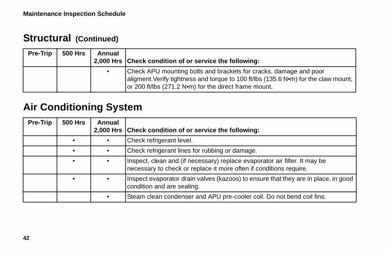
• Check APU mounting bolts and brackets for cracks. damage and poor aligment.Verify tightness and torque to 100 ft/lbs (135.6 N•m) for the claw mount, or 200 ft/lbs (271.2 N•m) for the direct frame mount.
Structural (Continued)
Pre-Trip 500 Hrs Annual 2,000 Hrs Check condition of or service the following:
Air Conditioning System Pre-Trip 500 Hrs Annual
2,000 Hrs Check condition of or service the following:
• • Check refrigerant level.
• • Check refrigerant lines for rubbing or damage.
• • Inspect, clean and (if necessary) replace evaporator air filter. It may be necessary to check or replace it more often if conditions require.
• • Inspect evaporator drain valves (kazoos) to ensure that they are in place, in good condition and are sealing.
• Steam clean condenser and APU pre-cooler coil. Do not bend coil fins.
Maintenance Inspection Schedule
43
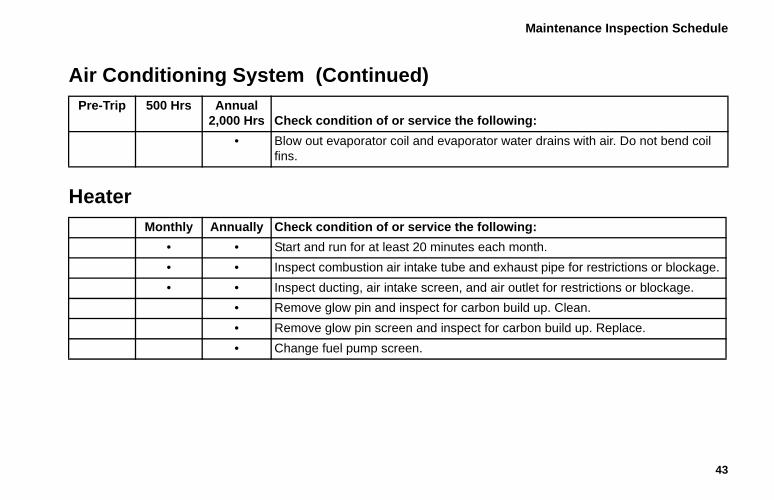
• Blow out evaporator coil and evaporator water drains with air. Do not bend coil fins.
Air Conditioning System (Continued) Pre-Trip 500 Hrs Annual
2,000 Hrs Check condition of or service the following:
HeaterMonthly Annually Check condition of or service the following:
• • Start and run for at least 20 minutes each month.
• • Inspect combustion air intake tube and exhaust pipe for restrictions or blockage.
• • Inspect ducting, air intake screen, and air outlet for restrictions or blockage.
• Remove glow pin and inspect for carbon build up. Clean.
• Remove glow pin screen and inspect for carbon build up. Replace.
• Change fuel pump screen.

44
TriPac WarrantyTerms of the Thermo King Warranty are available on request. Please reference document TK 50046 for the Thermo King TriPac Warranty.
45
Serial Number LocationsAPU: Unit nameplate is located on front right edge of APU frame near the Engine On/Off Switch. Open the service access door to view the nameplate.
Engine: Nameplate is located on the top of the engine inside the TriPac APU.
Compressor: Nameplate is located on compressor body. The compressor is located inside the TriPac APU.
Heater: Nameplate is located on the side of the heater. The heater is typically installed in the cargo compartment or under the truck cab sleeper compartment.
46
Emergency Cold LineIf you can’t get your rig rolling, and you have tried the Thermo King North American Service Directory (available from any Thermo King dealer) to reach a dealer without success, then call the Toll Free Emergency Cold Line Number (888) 887-2202.
The answering service at the factory will assist you in reaching a dealer to get the help you need. The Cold Line is answered 24 hours a day by personnel who will do their best to get you quick service at an authorized Thermo King Dealer.
AMA1585
47
Recover Refrigerant
At Thermo King, we recognize the need to preserve the environment and limit the potential harm to the ozone layer that can result from allowing refrigerant to escape into the atmosphere.
We strictly adhere to a policy that promotes the recovery and limits the loss of refrigerant into the atmosphere.
In addition, service personnel must be aware of Federal regulations concerning the use of refrigerants and the certification of technicians. For additional information on regulations and technician certification programs, contact your local THERMO KING dealer.
48
CALIFORNIAProposition 65 Warning
Diesel exhaust is a chemical known to the State of California to cause cancer.

Operator’s Manual
Operator’s Manual
Ingersoll Rand’s Climate Solutions sector delivers energy-effi cient HVACR solutions for customers globally. Its world class brands include Thermo King, the leader in transport temperature control and Trane, a provider of energy effi cient heating, ventilating and air conditioning systems, building and contracting services, parts support and advanced controls for commercial buildings and homes.
Ingersoll Rand’s Climate Solutions sector delivers energy-effi cient HVACR solutions for customers globally. Its world class brands include Thermo King, the leader in transport temperature control and Trane, a provider of energy effi cient heating, ventilating and air conditioning systems, building and contracting services, parts support and advanced controls for commercial buildings and homes.
©2013 Ingersoll-Rand Company Printed in U.S.A.
©2013 Ingersoll-Rand Company Printed in U.S.A.
TriPac EVOLUTIONAuxiliary Heating/Cooling
TemperatureManagement System
TK 55711-19-OP (Rev. 3, 12/17)
TriPac EVOLUTIONAuxiliary Heating/Cooling
TemperatureManagement System
TK 55711-19-OP (Rev. 3, 12/17)